energy trnsfer studies in uqterhalogen … laser are also presented. 14. subject terms 1s. number of...
TRANSCRIPT

AD-A262 888PSI-1085/TR- 1237 It1I ii j ri
ENERGY TRNSFER STUDIES IN UqTERHALOGEN MOLECULES
DTICPrepared by: ELECTE
S.i. Davis APR 1 1993K.W. Holtzclaw DW.J. KesslerL.G. Piper
Physical Sciences Inc.20 New England Business CenterAndover, MA 01810
Final Report
January 1993
Contract No. F49620-89-C-0101
Prepared for:
USAF,Asc 93-06615Air Force Office of Scientific ResearchBuilding 410 IIIIII$ IBIIII IIIBoiling AFB, DC 20332-6448
PHYSICAL SCIENCES INC. U......20 New England Business Center, Andover, MA 01810, U.S.A. i ~ *i
9 3 3 d7 i.-.t: .d.

REPORT DOCUMENTATION PAGE CM8,M a 74 N J
-own'N D.Of I~g~3f tn '01 - ;0.14 O'c V~ '.31fm4~o S" St oleo 0 A .41491, o .0" *, '#on _j- Q 't e *e-j- , .110C * A nt v'atan. 1.9a 110 '01 ' C .n ." ',, .. ..'. .io" ' ) ' ' W' V*1. . . ..
Oaaý,sm'ftf'*s Stf 1206 Athngtof V'A 22202 4302 01 to?, ,@ t"Co )l A4"90-"#- '1 "a.o l ý8000' % '* 4 6'-9' 0 'Iýd.C 0,136r ý' $8 ý66I.o ý-c
1 AGENCY USE ONLY fLeave blan*) 2 REPORT DATE 3 REPORT TYPE AND DATES COVERED
Januarv 1993 F ina
4 TITLE AND SUBTITLE 5 FUNDING NUMBEAS
Enerzy Transfer Studies in Interhaiozen 1,olecuicsC
6 AUTHOR(S) F49620-89-C-;) 1)
S.J. Davis, K.W. Holtzclaw, `'.J. Kessler, L.G. Piper
7 PERFORMING ORGANIZATION NAME(S) AND AOORESS4ES) 8 PERFORMING ORGANIZATION
REPORT NUMBER
Physical Sciences Inc.
20 New England Business Center PSIIO8S!TR_12'37Andover, MA 01810
9. SPONSORING/MONITORING AGENCY NAME(S) AND ADDRESS4ES) 10 SPONSORING, MONITORINGAGENCY REPORT NUMBER
USAF, AFMCAir Force of Scientific Research
Bldg. 410Boiling AFB, DC 20332-6448
11. SUPPLEMENTARY NOTES
1 2. OISTRIBUTION/AVAILABILUY STATEMENT J 12b. OiSTRISUT)ON CODE
distri'Lutioki ýin.Luited. .1
13. ABSTRACT (Maximum 200 woru)
This program is examining energy transfer processes in interhalogen molecules that have potentialfor visible chemical laser development. Spectrally resolved laser induced fluorescence is used todetermine rotation-to-translation (R-T) and vibration-to-translation (V-T) rate coefficients. In thisreport we compare several fitting laws for R-T transfer to data obtained for IF and ICIinteractions with several collision partners. We have also obtained preliminary data on V-Trelaxation within the ground electronic state of IF. Preliminary results of an optically-pumpedHF laser are also presented.
14. SUBJECT TERMS 1S. NUMBER OF PAGES
Energy transfer, Laser excitation, Laser induced 16 PRICE CODE
fluorescence, Amplified spontaneous emission17. SECURITY CLASSIFICATION 18. SECURITY CLASSIFICATION 19. SECURITY CLASSIFICATION 20. LIMITATION OF
OF REPORT OF THIS PAGE OF ABSTRACT ABSTRACT
Unclassified Unclassified Unclassified
NSN 7S40-O1-23•0600 Standerd Form 296 IRev 2.89
236-02

Un c Lis sif ie dSEC"AII'V -.. ASSIF<A' -04 Df 9-S-CLASSIFIED By
DECL.ASSIFY ONa
t SSCpM g,2"FjrtoftQF T ISPEUnclasifie

DTIC QUALF:1,ý, --- ,
A.ceCo For "
rIfS CRA&IFINAL PROJECT SUMMARY UJIC TAB
1. TITLE: Energy Transfer in Interhalogen Molecules
2. PRINCIPAL INVESTIGATOR: Dr. Steven J. Davis A•,idbty e
3. INCLUSIVE DATES: 15 August 1989 - 15 November 1992 , .
4. CONTRACT/GRANT NUMBER: F49620-89-C-0101
5. COSTS AND FY SOURCE: FY89-92 $284,633
6. SENIOR RESEARCH PERSONNEL: Dr. Steven J. Davis (Principal Investigator)
7. JUNIOR RESEARCH PERSONNEL: Dr. Karl Holtzclaw, Mr. William Kessler, andDr. L.G. Piper
8. PUBLIC ATIONS/PRESENTATIONS:
1. "Rotational Energy Transfer in Excited States of Halogen Molecules. I.Transfer from v'=6, J'=72 in IF B3 1I". S. J. Davis and K. W. Holtzclaw, J.Chem. Phys. 22, 1611 (1990)
2. "Collisional Dynamics of the BrCl B311 State. I. Electronic Quenching." G.P. Perram and S. J. Davis, J. Chem. Phys. 29, 1720 (1990)
3. "Excitation of IF(B) by Metastable 02. I. Studies Involving IF(X,v)." S. J.Davis and A. M. Woodward, J. Phys. Chem. 29, 4610 (1991).
4. "Collisional Dynamics of the BrC1 B31I State. II. Vibrational and RotationalEnergy Transfer*. G. P. Perram and S. J. Davis, J. Chem Phys 2B, 373(1993)
5. "Amplified Spontaneous Emission in 12, New Observations", J. W. Glessnerand S. J. Davis, J. Appl. Phys. 72, (In Press)
6. "Rotational Energy Transfer in ICI(B). Comparisons to Scaling LawPredictions". S. J. Davis and K. W. Holtzclaw, (Submitted to J. Chem.Phys.)
7. "Enhancement of Electronic Energy Transfer in IF". S. J. Davis and W. J.Kessler, Chem. Phys. Lett. (In preparation).
1

I8. "Studies of a Dye Laser-Pumped Atomic Iodine Laser". S.J. Davis and L.
Hanko, Proceedings of "Lasers 92", Houston, TX (1993, in press).
9. "Optically-pumped HF Laser Based on Overtone Pumping". S.J. Davis, W.J. IKessler, G. Hager, and H. Miller, Proceedings of "Lasers 92", Houston, TX(1993, in press).
10. "Engergy Transfer Processes in Diatomic Halogens", S.4. Davis, K.W.Holtzclaw, and W.J. Kessler, Proceedings of "Lasers 92", Houston, TX(1993, in press).
IIIIIIIII1II
2!
I

9. ABSTRACT OF OBJECTIVES AND ACCOMPLISHMENTS:
A. jectives
The objective of this project is to study energy transfer processes in selected halogenmolecules. In particular, we are examining rotational to translational (R-T) and vibrationalto translational (V-T) transfer in the B(31I) states of IF, ICI, and 12. We also examine R-Ttransfer during inelastic vibrational collisions. The experiments are conducted using a singlefrequency CW dye laser as the excitation source. With this laser, molecules can be preparedin a pure quantum state (v',J'). The resulting B-*X fluorescence is spectrally resolved, andthe rate coefficients for energy transfer are determined using a steady state kinetic analysis.In brief, the ratio of the fluorescence intensity from a satellite collisionally populated level(If) to that of a parent laser excited level (Ji) is directly proportional to the R-T rate, kti-t)-Knowledge of the radiative lifetime of the level Ji is required in the analysis. The lifetimesof the states being investigated have been previously determined.
The R-T rate coefficients are desired for two reasons. First, they are used to test parenttheoretical scaling laws that predict the dependences of ki upon Ji and upon the change inJ (AJ) during a collision. These are of importance because the scaling laws depend upon theintermolecular potentials. Thus, fundamental insight is gained from these measurements.Secondly, these measurements have great practical relevance. Many of the species beinginvestigated are excellent candidates for electronic transition chemical lasers. The degrees ofR-T relaxation in the excited state will in large measure determine the efficiency of the laser.In addition, knowledge of the R-T rates in the excited B state is useful for estimating R-Trelaxation in the ground state.
We have also been examining vibrational and rotational energy transfer within the groundelectronic state of IF. Relaxation processes within the ground state are crucial to theefficiency and ultimate scaling of an electronic transition laser. In this report we describepreliminary results for V-T relaxation for high vibrational levels within IF(X).
We also performed some optically pumped laser studies in the molecules 12 and ICI. Thisprovided a testbed for some of the RET and V-T relaxation studies. In addition theseoptically-pumped lasers can yield some valuable information concerning the spectroscopy andradiative dynamics of the excited states of the laser species.
During the contract there appeared in the literature reports concerning optical gain in the 04complex. The dimole is observed in chemical singlet delta generators that are used in thechemical oxygen iodine laser. We performed some spectral modelling studies in an attemptto discern possible emitters in this system. We focused on the B-X system in molecularchlorine and were able to reproduce some of the features that had been reported.
In the final year of this effort we have been examining the feasibility of developing mid-IRlasers based upon optically pumped gas phase media. These lasers would fill an importantAir Force mission in asset defense. We describe several experiments that have beenperformed near the end of this contract.
3

I
B. Progress (Finalj)
We completed the following activities during this effort: I
Extensive data collection for collisions of ICI and molecular collision partners.
Detailed analysis of RET data sets for both ICI and IF.
Comparisons of fitting and scaling laws for RET transfer
Preliminary rate coefficients for V-T relaxation within the ground electronic Istate of IF.
Optically-pumped laser studies on the B-X systems of 12 and ICI. ISpectral modeling in support of reports in the literature concerning thepossibility visible laser action in oxygen dimole emission. aDemonstration of amplified spontaneous emission in HF following excitationof overtone bands.
We describe each of these items below. IB. I Data collection for ICI collisional processes. IIn the previous reporting period we had obtained some preliminary RET data for IC .During the present period we extended these measurements considerably. The apparatus forthese measurements is shown in Figure 1. The ring dye laser is used to prepare IC I Imolecules in a single rovibrational level within the electronically excited B state.We use a high resolution spectrophotometer to resolve the laser-induced fluorescence thatresults from the laser excitation. A 1.26m Spex monochromator with an intensified1024-element diode array comprised the spectrophotometer. This device provides spectralresolutions on the order of 0.06 nm which is sufficient to resolve many rotational lines.Accurate and reproducible placement of the diode array at the focal plane of the high-resolution monochromator is crucial for the operation of the instrument.
The dye laser (Coherent Model 699-05) was not actively stabilized, but its stability wassufficient for the experiments performed. The linewidth of the dye laser was measured witha large frame scanning Fabry-Perot interferometer (Burleigh Model 140). The measured glinewidth was less than 70 MHz which is much less than the room temperature Doppler
4I

Wavemeter Dye Lasego Ion Laser
"--iu I eMonochromator
w ()ft a Fluorescence Cell d r tio t eMultichannel-Analyzer(•)=•=Display
--Gas
System
"-"rueFigure I
Block Diagram for the Apparatus used in the Rotational Energy Transfer Measurements
width (600 MHz) for the ICI absorption lines. Wavelength determination of the dye laserwas accomplished using a Burleigh Model WN-20 wavemeter. The spectral purity, i.e.,longitudinal mode behavior was continuously monitored using a Trope] Model 240 confocalspectrum analyzer.
ICI was produced off-line in a pyrex flask that contained IC13 crystals. The vapor above thissolid is predominately ICI and C12 . The Cl2 reactively removes any 12 vapor. This is animportant advantage since the strong and spectrally dense iodine B-X absorption systemoverlaps and interferes with the weaker ICI system. Using this approach, we observed no 12interferences.
The fluorescence observation chamber was constructed from a brass block that contained LIFobservation windows and sidearms for the introduction of the dye laser beam. Lightcollection and focusing of the fluorescence onto the entrance slit of the monochromator wasaccomplished using a system of aspheric and spheric lenses. The f-number of the imagingsystem was carefully matched to that of the monochromator to maximize both throughput andresolution.
We completed data collection for the ICI molecule during this reporting period, and haveconcentrated recently on the data analysis and interpretation. The IF and ICI data collectionsets and scope of the study are summarized in Tables I and 2.
5

I
Table 1. Summary of the Rotational Energy Transfer Processes and Collision !Partners Studied for the IF Molecule.
J' Level Excited I Excitation Band Observed Band Bath Gases
13 6,7 6,0 He, Ar, Xe
27 6,7 6,0 He, Ar, Xe
35 6,7 6,0 He, Ar, Xe 372 6,0 6,0 He, Ne, Ar, Kr, Xe, N2 , CF4
13 6,7 5,0 He, Kr
72 6,0 5,0 He, Kr ia
Table 2. Summary for the R-T Transfer Process and Collision Partners Studied in IC 1(B)
Excitation 1J' Level Excited Frequency (cm"1 ) Observed Band Bath Gases
11 17095.24 1-7 ICi 119 17095.04 1-7 ICi22 17080.29 1-7 He, Ar, IC126 17088.26 1-7 CO, HF 127 17075.48 1-7 He, Xe, Kr, 0235 17075.24 1-7 He, Xe, Kr, 02
He, Ar, ICI36 17073.51 1-7 ICI, CO, HF40 17065.99 1-7 IC 142 17043.50 1-8 He, Ar, IC1 It55 17029.44 1-7 He, Ar, IClI56 17001.89 1-7 He, Xe, Kr, 0257 16998.47 1-7 ICI60 17014.32 1-7 ICI, CO, HF 1
61 16984.22 1-7 Kr, ICI70 16979.66 1-7 He70 16979.66 1-8 He, Xe, 0278 16947.62 1-7 IC1
I

One particularly interesting aspect of the ICI results was the observation of efficientrotational energy transfer when ground state ICI is used as a collision partner for the ICI(B).As we discuss below, this effect also needs to be taken into account in the data reduction forR-T transfer when other species are used as collision partners.
B.2 Data analysis for determination of R-T rate coefficients.
The determination of R-T rate coefficients was based upon a steady state kinetic analysis. Indilute conditions where a fluorescing molecule experiences on average only a single collisionduring its lifetime, the steady state expression for the population of the final state is given byEq. (1):
d[Jf] [f]d -- [Ji][M]k(i--,f) - [J =0 (G)
dt
This equation can be rearranged to give the working expression used to derive the R-T ratecoefficients:
= [M]k(i-..f) T (2)[Ji]
where [Ji] and [Jf] are the relative populations of the initial and final states, k(i-f) is the ratecoefficient for the transfer from Ji to Jf, and r is the effective lifetime of Jf. When the singlecollision assumption is valid, a Stern-Volmer plot of [Jf]/[Ji] versus [M] will be linear in [M]and the slope will be proportional to the R-T rate coefficient. In our experiments, care wastaken to avoid bath gas pressures that were high enough to produce multiple collisions.Within the inherent scatter of the data, linear plots Stern-Volmer plots were always observedin this work. Previously 1 , we presented a detailed discussion of multiple-collision effectsand the tests that we use to check for such effects. We do not repeat them here.
The effective lifetime in Eq. (2) is given by:
1r = 1(3)kR +(kq +kv)tM] +kp
where kq, kp, kv, and kR are the respective rate coefficients for electronic state quenching bythe collision partner, predissociation, vibrational energy transfer, and radiative decay. Manyof these rate coefficients are known or are negligible for IF(B) and ICI(B). For example,electronic state quenching of IF(B) by the noble gases, CH 4 , and N2, has been measured andis uniformly inefficient 2 . The effects of quenching by the bath gases were thus minor inthese experiments, but were nonetheless included. Vibrational transfer was accounted forusing the rate coefficients measured for IF(B) in collision with the noble gases and N2 by
7
I
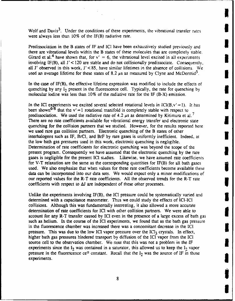
Wolf and Davis 3. Under the conditions of these experiments, the vibrational transfer rates iwere always less than 10% of the IF(B) radiative rate.
Predissociation in the B states of IF and ICI have been exhaustively studied previously and Ithere are vibrational levels within the B states of these molecules that are completely stable.Girard et al. 4 have shown that, for V = 6, the vibrational level excited in all experimentsinvolving IF(B), all J' < 120 are stable and do not collisionally predissociate. Consequently,all F observed in this work, < 85, have similar lifetimes in the absence of collisions. Weused an average lifetime for these states of 8.2 ps as measured by Clyne and McDermid5 . I
In the case of IF(B), the effective lifetime expression was modified to include the effects ofquenching by any 12 present in the fluorescence cell. Typically, the rate for quenching bymolecular iodine was less than 10% of the radiative rate for the IF (B-X) emission.
In the ICI experiments we excited several selected rotational levels in ICI(B,v'= I). It has ibeen shown 6-8 that the v'= 1 rotational manifold is completely stable with respect to 7predissociation. We used the radiative rate of 4.2 tAs as determined by Kitimura et al. 7
There are no rate coefficients available for vibrational energy transfer and electronic statetquenching for the collision partners that we studied. However, for the results reported herewe used rare gas collision partners. Electronic quenching of the B states of otherinterhalogens such as IF, BrCl, and BrF by rare gases is uniformly inefficient. Indeed, at ithe low bath gas pressures used in this work, electronic quenching is negligible.Determination of rate coefficients for electronic quenching was beyond the scope of thepresent program. Consequently we have assumed that the electronic quenching by the rare Igases is negligible for the present ICI stidies. Likewise, we have assumed rate coefficientsfor V-T relaxation are the same as the corresponding quantities for IF(B) for all bath gasesused. We also emphasize that when values for these rate coefficients become available these Udata can be incorporated into our data sets. We would expect only a minor modifications ofour reported values for the R-T rate coefficients. All the observed trends for the R-T ratecoefficients with respect to 4.J are independent of these other processes.
Unlike the experiments involving IF(B), the ICI pressure could be systematically varied anddetermined with a capacitance manometer. Thus we could study the effects of ICl-IC1collisions. Although this was fundamentally interesting, it also allowed a more accuratedetermination of rate coefficients for ICI with other collision partners. We were able toaccount for any R-T transfer caused by ICI even in the presence of a large excess of bath gassuch as helium. In the course of the ICI experiments, we found that as the bath gas pressurein the fluorescence chamber was increased there was a concomitant decrease in the ICIpressure. This was due to the low ICI vapor pressure over the IC13 crystals. In effect,higher bath gas pressures hindered transport by diffusion of the ICI vapor from the ICIsource cell to the observation chamber. We note that this was not a problem in the IF 1experiments since the 12 was contained in a saturator, this allowed us to keep the 12 vaporpressure in the fluorescence cell constant. Recall that the 12 was the source of IF in thoseexperiments.
8 I

We modified our data reduction routines for the ICI data to account for the self transfer.This represents an important addition to the data analysis since we found that ICI has muchlarger rate coefficients for RET than other collision partners we have investigated. As aresult, ICI + ICI collisions have an important effect on the determination of R-T ratecoefficients with other collision partners.
The presence of ICI in the gas mixture leads to corrections due to self-quenching, vibrationaltransfer, and R-T transfer. The corresponding effective lifetime for ICI(B) is then given by:
1kR+kp+(kl +kM)[M] +( kIC0 +kICl)[Id1 (4)
This results in a modified Stern-Volmer expression:
[0t- - kIC, (iDf) [ICl1 • r M k (i-0)M] • r (5)
where k4 Cl(i--f) is the rate coefficient for R-T transfer due to ICI(B) colliding with IC. Weemployed the value of 2. ' x 10-10 cm 3 molecule 1 s- for kq as determined by Kitimura
et al.8
In order to apply Eq. (5), the rate coefficients for kA4Cl must be determined. We used theinitial Stern-Volmer analysis described above with ICI as the collision partner for thedetermination of rate coefficients for self R-T transfer out of several initially excitedrotational levels in ICI(B,v'=I): Ji = 61, 57, 39, and 35. The resulting rate coefficientswere somewhat scattered, consequently, they were both averaged and smoothed prior to usein Eq. (5). The coefficients from Ji =57 and 61 were smoothed and averaged and then usedto correct the data from other collision partners where Ji Ž 56. A similar procedure wasemployed for the coefficients from 1i = 35 and 39 and the resulting coefficients were used tocorrect the data from Ji <_ 36 for other bath gases. Figure 2 shows a set of smoothedcoefficients. These rate coefficient sets were used to modify the population ratios [Jf]/[Ji] bymeans of Eq. (5). In Figure 3 we present an example of the effect of this treatment for thecase of ICI + Kr collisions. Both the uncorrected rate coefficients and those corrected forself transfer are shown.
B.3 Spectral fitting.
The relative populations of the initial and final states used in Eqs. (2) and (5) were measuredusing the intensities of the respective P- and R-branch transitions from these levels (the-C areno Q-branch transitions due to symmetry restrictions). I The relationship between the relativeintensities and relative populations is given in Eq. (6):
9

III
Se I
10-0.
.o10-11
- L I5 i
10-12
-50 -30 .10 10 30
4AJ(Ji - Ji) 848 m 3Figure 2
Distribution of R-T Rate Coefficients for Self Relaxation by ICI. The data have beensmoothed as described in the text. These data were applied in the determination of rate
coefficients for RET due to other collisior partners where Ji -> 56.
I,, = N * " ~!q~v J+ (6
where Sj, j,, is the rotational linestrength, v is the transition frequency, Re is the electronicItransition 'moment, and qv,,v, is the Franck-Condon factor. m
The relative intensities in Eq. (6) can be determined either by measuring the peak intensities
or the integrated intensities of the corresponding transitions. Since the spectral resolutionavailable to us was insufficient to completely resolve all the observed transitions, we ameasured integrated intensities from each J' using a spectral fitting program that allows the
10 1I

10-10 A
• 10-11
0
E
. 10-12 -
10-13 - ,-50 -40 -30 -20 -10 0 10 20 30 40
&J (Jf -Ji) B-78)
Figure 3Comparison of R-T Rate Coefficients That Have Not Been Corrected for Self Transfer (+)
to Those That Have Been Corrected (0) Using the Treatment Described Above.Collision partner was krypton.
determination of populations from dispersed fluorescence spectra even when substantialoverlap occurs. The spectral fitting procedure is described in detail in Ref. I.
We have consistently observed a bleed over on the diode array for pixels immediatelyadjacent to those illuminated by the relatively intense radiation from transitions originatingfrom the parent Ii. This made accurate determination of populations for nearby Jf difficult.Consequently, we have not included levels immediately adjacent to the Ji in the data analysis.We feel that this is an inherent difficulty when using a diode array detector. However, tJeadvantages in data collection efficiency far outweigh this slight deficiency.
We also found that the fitting code would calculate populations for levels radiating in regionsof the spectrum where there is severe overlap, e.g., near the bandhead. The populations
11

determined under these conditions do not always vary smoothly from one rotational level to Ithe next, particularly if the signal to noise in the fluorescence spectrum is poor. This waslargely responsible for much of the scatter in the data from lower Jf with IF(B). 3The spectral constants of Tricki and Wanner 9 were employed for the fitting of the IF spectra.The constants are in the Dunham expansion format and were found to give extremelyaccurate line positions. Indeed it was found that the ring laser could be tuned to any desired Utransition using the calculated line positions and the wavemeter.
The spectral constants of Brand and Hoy1 0 were used for ICI(X) and those of Clyne and IMcDermid 7 were used for ICI(B). Both sets of spectral constants are consideraoly lessextensive and refined than those used to calculate the IF(B-X) spectra. Accuratemeasurement of these spectral constants, though possible with the equipment available forthis program, was outside the scope of this effort. Deficiencies in the constants manifestthemselves as a "dephasing" of the calculated and observed rotational lines at large 3displacements from the originating from the initially pumped rotational level. This wasprimarily a problem with the data from the lower rotational levels (Ji .- 40) since largerpositive AJ transfer is possible with these levels. Because of this difficulty, rate coefficientsIfrom these data are somewhat less reliable and were not used in the testing of the fittinglaws. i
B.4 The fitting laws.
We have tested a single variant of each of four laws that describe rotationally inelastic energy Itransfer in an attempt to determine simple closed form expressions for the rate coefficientmatrix describing RET in these systems. The exponential gap law (EGL) and the statisticalpower gap law (SPG) scale the calculated rate coefficients with the rotational energy change Iresulting from the collision. The energy corrected sudden law (ECS) and the infinite ordersudden law (10S) scale the rate coefficients with the angular momentum exchanged duringthe collision. These fitting laws are described in detail in Refs. 11 through 13.
The exponential gap law (EGL) is the oldest fitting law and was originally proposed byPolanyi and Woodal114 to account for RET resulting from HF-HF collisions. This law has Ibeen subsequently shown to be consistent with surprisal theory (Ref. A and referencestherein) and is given by: 3
EGL (0 ,1ERT 1)(7)kEG(i-) -- a • e (-IAERoTI) R(AE) • (2Jf+) Iwhere a and O are the fitted parameters, AE is the difference in rotational energy between Ji 3and Jf, and R(AE) is the ratio of final to initial translational state densities. Inclusion of theterm 2Jf + 1 corresponds to the assumption that all final mj states are accessible in thecollision.
1

The statistical power gap law (SPG) was originally proposed by Brunner et al. 15 to accountfor RET in collisions between Na2 and Xe and has since been applied with some success todata from Na2 in collision with additional bath gases 13 and 12 in collisions with He andXe16 . This law differs from the exponential gap law in that rate coefficients scale as apower of the energy difference. It is given by:
k SPG a I ("ERO,&E(i-.-) B • No(J? ) (R(aE) (8)B
where a, a, and X are the fitted parameters and Bv is the rotational constant. We haveemployed a version of this law that allows restrictions to be placed on Amp. Theserestrictions are contained in the factor Nx and are determined by the parameter X. Thisprovision allows limits on the relative spatial orientation of the rotating molecule before andafter a collision. When lambda exceeds Ji + Jf, N, reaches a limiting value of 2 Jf + I andthere is no longer a restriction in Amp.
The energy-corrected sudden law was originally proposed by DePristo et al. 17 and arisesfrom the sudden approximation of inelastic scattering theory. It has been applied withsuccess to RET in several systems 11-13, 18. This law is given by:
kECS(Ji.-Jf) = (2jf + 1) exp[(Eii - Ej>)/kT]
xJi Jf (2e t - 1) Aj> k(t--,O)L E 000j f
where the term in brackets is a 3-j symbol, J> is the larger of Ji and Jf, and the sum over eranges from I Ji - Jf I to I Ji + Jf I . The k(1--,0) are referred to as basis rate coefficientsand describe transfer out of Ji = 0. In principle these quantities can be measured, howeversuch measurements present substantial difficulties (e.g., isolating a transition populating J0 and resolving the resulting fluorescence). Consequently, like other investigators, weemploy one of several analytic forms, in this case given by Eq. (10):
k(t--O) = ce( l (10)
where a and -y are the variable parameters. This form for the basis rate coefficients hasbeen successfully used to fit rate coefficients from the I2 (B) + Xe, He, 16 and Na 2(A) incollisions with several gases. 13 The term Aj > is an adiabatic correction allowing formolecular rotation during the collision and is given by:
13

3
A - 2 /6
i + >
where rj is a reduced collision duration given as the number of radians rotated by themolecule during the collision (rj = wj x Td). The collision duration Td is equal to lIc/v Iwhere 1c is an average effective collision length and v is the mean closing velocity of thecollision pair. Along with the terms in the basis rate coefficients, Ic can be varied in orderto best fit the data.
The infinite order sudden (IOS) law is a simplification of the energy corrected sudden law Iwhere the effective collision length is assumed to be zero. The expression for the infiniteorder sudden law as applied in this analysis is given by Eq. (9) where the adiabaticcorrection term Aj > is now unity. This law would be expected to be most appropriate forcollisions with light, fast moving collision partners which are more likely to produce shortimpulsive collisions.
The fitting of data was performed using a non-linear least squares program based on theLevinburg-Marquardt method as found in Bevington19. This is a rapidly convergingalgorithm which attempts to produce a "best fit" by minimizing the reduced chi square Ifunction given by:
X2 + [(kflt(i-"f)-kexpt(if))]2 (12)Jf a2(i.f)
where , is the number of independent degrees of freedom in the fit (number of experimentaldata points minus the number of fitted parameters) and a are the individual errors associatedwith the rate coefficients. For the ao we used the errors produced by the least squares fittingroutine used to determine the rate coefficients. These are also chi square functions describingthe deviation of the experimental population ratios from the best fit line giving the ratecoefficient.
Data from all Ji for a given collision partner were used simultaneously in a global fit. We Ipresent two figures of merit to judge the quality of the fit: the reduced chi-square and theaverage percent deviation between the calculated and experimental rate coefficients.
B.5 Visible optically-pumped laser.
In an effort to demonstrate further the potential of the interhalogens as visible lasercandidates, we completed a study in which we attempted to produce an optically-pumped ICI(B-X) laser. The apparatus for this study is shown in Figure 4. The excitation source was a
14 UU

cc'
a E->C
0 M
q2 -7
coaCD0
B CIO)CM CL
Q -
c U~
h>=
E~ 00cr
15

I
Quantel Nd:YAG laser pumped dye laser. A mix of LD 590 and LD 610 laser dyes I(Exciton) was used to produce output energies in excess of 10 mJ over the wavelength rangeof 580 and 610 nm. The selection of the excitation wavelengths for the ICI depend criticallyupon the Franck-Condon factors for absorption and the stability of the ICI B-state manifold. ISince all the levels v' >3 are predissociated, only a rather limited range of excitationschemes are available. In Table 3 we list the excitation bands considered and indicate therelative absorption strengths (product of the relative population and the Franck Condon Ifactor).
Table 3. [CI (B-X) Bands used in the OPL Studies i
vivl qvova 0 ,,wb Jv.v 0 E)
0,0 8 x 10⁻⁷ 0.84 6.7 x 10-71,0 6 x 10⁻⁶ 0.84 5.0 x 10-62,0 2 x 10⁻⁵ 0.84 1.7 x 10-51,1 9 x 10⁻⁵ 0.13 1.1 x 10-52,1 3 x 10⁻⁴ 0.13 3.9 x 10-42,2 2 x 10⁻³ 0.02 4 x 10⁻⁴
"aFranck Condon factor.bRelative v" population of 300 K.
B.6 "04 laser" support. IWe have been following closely the reports of 04lasing in chemically-generated oxygen. The workby Yoshida et al.2°attributed visible wavelengthemissions to the 04 molecule. We were intriguedby the report of lasing in a species such as 04,which has an extremely high predissociation ratebut a relatively small radiative rate. Indeed, thecollisional nature of 04* would make lasingextremely difficult to obtain.
The spectra reported by Yoshida et al. 20 arereproduced in Figure 5. In a search for otherpossible sources for this emission we consideredthe well known C12 (B-.X) emission system. 2
Molecular chlorine is the primary gaseous "fuel" 600 700 800in a chemical oxygen generator. Although the I1generators are typically run under conditions B (n) 8-4240
where the Cl2 is completely consumed theexistence of C12 in the 02 flow has been observed Figure 5 Ipreviously. "04" Spectrum (from Yoshida et al.) 20
16 1I

I
1B.7 Ground state relaxation in the ground state of IF.
For electronic transition laser applications, relaxation within the ground electronic is animportant process. In many laser systems, relaxation out of the terminal rotational level willbe rate limiting in the limit of high power operation, i.e., for large stimulated emission ratesbottlenecking will occur. In previous optically pumped IF laser studies, we saw evidence ofthis phenomenon in high power operation of the IF laser. Since rotational relaxation isusually much faster than vibrational relaxation, it is the most important in terms of
I bottlenecking.
Vibrational relaxation within the ground electronic state can also play an important role insome energy transfer excitation schemes. For example. Davis and Woodward2 1 have shownthat population within high vibrational levels of IF(X) significantly enhance the productionrate of IF(B) in the presence of 0 2 (a). This internal vibrational energy apparently opensenergy transfer pathways that otherwise would be inaccessible. The immunity of thesevibrational levels to electronic quenching will be important in any pressure scaling of the IFlaser. Consequently, we have made preliminary measurements of vibrational relaxation ofselected levels within the ground electronic state.
These measurements were performed on the apparatus shown in Figure 6. The IF(X,v) wasproduced by reacting either ICI or 12 with F atoms. As indicated in Figure 6, the fluorineatoms were produced by passing a flow of helium and CF 4 through a microwave discharge
Micro n oI Computer]t
III Figure6.
HA Boxcar fecIF.NF3/M 00-- 2 Averager Rcre
SI I I 111-1 /'-:• 3''--Filter
" -.-l == = : •= == =• I 0. o I _.Vacuum• • Pump
[ I Computer
Figure 6Apparatus Used for the Initial Studies of Relaxation of Ground State IF.
17

I
cavity. The reactions of ICI or I-) with F are known to produce IF(Xv) with high Iefficiency. 22 In addition the exothermic limits of for the respective reactions are v" =9 andv"= 19. Thus, we could prepare flows of IF(X,v) that could be used to study vibrationalrelaxation.
We monitored the relative concentration of IF(X,v) using Stokes shifted laser inducedfluorescence. We note that excitation wavelengths that connect high vibrational levels inIF(X) to IF(B) are in the range 600 to 700 nm. These are conveniently produced using a dyelaser. We used a pulsed, frequency doubled Nd:YAG laser as indicated in Figure 4. 3The LIF was detected using GaAs PMT and a narrow bandpass interference filter centered at490 nm. This combination allowed us to probe levels 6<v"< 14.
In Figure 7 we show a sample spectrum of LIF from several v" levels. The rotationalstructure is partially resolved for each band observed. The intensity of each LIF band isproportional to the population within the v" level that is excited by the dye laser. Thus, wecan use the LIF spectra to determine the relative population of selected v" levels.
As indicated in Figure 6, we used a sliding injector to introduce the ICI into a flow of F 3atoms and the bath gas that we wished to study. The observation port was fixed, and thedistance from the injection point for the ICI and the to the observation port determined thereaction time. All observations were dce far enough downstream so that mixing corrections Iwere negligible.
150 1140 -130 - (3,8) (4,9)
120 -110 - IF(X,V) Formed
100 - from F + 12
! 90-C 80-
S70 -"LL (6,10)"- 60
40 (7,11) I20 IF(X) FORMED10 FROM F + CF31
643 645 647 649 651 653
Laser Wavelength (nm) 8.5983a
Figure 7 1Excitation Spectra Showing IF(X,v) Produced from the Reactions of 12 + F and CF 3I + F.
18
I
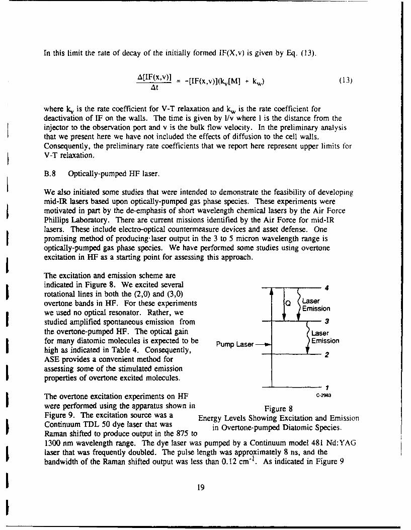
In this limit the rate of decay of the initially formed IF(X,v) is given by Eq. (13).
A[IF(x,v)] = [IF(x,v)](kv[M] + k,) (13)at
where kv is the rate coefficient for V-T relaxation and kw is the rate coefficient fordeactivation of IF on the walls. The time is given by I/v where I is the distance from theinjector to the observation port and v is the bulk flow velocity. In the preliminary analysisthat we present here we have not included the effects of diffusion to the cell walls.Consequently, the preliminary rate coefficients that we report here represent upper limits forV-T relaxation.
B.8 Optically-pumped HF laser.
We also initiated some studies that were intended to demonstrate the feasibility of developing
mid-IR lasers based upon optically-pumped gas phase species. These experiments weremotivated in part by the de-emphasis of short wavelength chemical lasers by the Air ForcePhillips Laboratory. There are current missions identified by the Air Force for mid-IRlasers. These include electro-optical countermeasure devices and asset defense. Onepromising method of producing-laser output in the 3 to 5 micron wavelength range isoptically-pumped gas phase species. We have performed some studies using overtoneexcitation in HF as a starting point for assessing this approach.
The excitation and emission scheme areindicated in Figure 8. We excited several 4rotational lines in both the (2,0) and (3,0)overtone bands in HF. For these experiments O Laser
we used no optical resonator. Rather, we Emission
studied amplified spontaneous emission from 3the overtone-pumped HF. The optical gain Laserfor many diatomic molecules is expected to be Pump Laser --o Emissionhigh as indicated in Table 4. Consequently, 2ASE provides a convenient method forassessing some of the stimulated emissionproperties of overtone excited molecules.
1
The overtone excitation experiments on HF C-23
were performed using the apparatus shown in Figure 8Figure 9. The excitation source was a Energy Levels Showing Excitation and EmissionContinuum TDL 50 dye laser that was in Overtone-pumped Diatomic Species.Raman shifted to produce output in the 875 to1300 nm wavelength range. The dye laser was pumped by a Continuum model 481 Nd:YAGlaser that was frequently doubled. The pulse length was approximately 8 ns, and thebandwidth of the Raman shifted output was less than 0.12 cm- . As indicated in Figure 9
19

I
Table 4. Predicted Laser Parameters for Several Candidate Laser Systems IPump Apump aAB( 2*-O) NV, i GSE(2. ain
Molecule Band (j m) (acm2) (cm-) (cm) (cm" 1)
HCI (2,0) 1.73 6.4 x 10"9 1. 1 x 10'5 1.2 x 10⁵ 1.36 1HF** (2,0) 1.32 2.0 x 10-"18 4.9 x 10¹⁵ 1.9 x 10⁻¹⁵ 9.2
DF** (2,0) 1.78 9.1 x 10.19 2.1 x 10¹⁵ 1.4 x 10⁻¹⁵ 6.9 1COt 1 (2,0) 2.7 4.0 x 10⁻¹⁹ 7.8 x 10 14 1.2 x 10⁻¹⁵ 0.94 1Assuming 10 Torr of species, 2 mJ/10 ns laser pulse, beam diameter 6 mm, and pumplaser bandwidth of 0.1 cm
H2 Raman [Cell _ _Cell Filters DeecoS,,DetectorI
Monochromator(Optioral)
'•Handling
;System
Boxcar
Integrator 3Lab P.C. B-9066b 1
Figure 9Block Diagram of Apparatus Used in the ASE Experiments.
the HF cells were excited longitudinally. We used two cells, one was 112 cm long and thesecond cell was only 7.5 cm long. The cells were connected to a passivated gas handlingsystem and were pumped to less than 0. Im Torr prior to filling. Cells were filled with neatH-F or with mixtures of HF and He. Detection of both absorbed pump radiation and the HFASE were accomplished using a liquid nitrogen-cooled InAs detector. A series of long passand short pass optical filters were used to isolate the ASE emission. For some studies a
20
I

0.3m monochromator was used to spectrally resolve the ASE in oider to st ady energytransfer with.,• the excited Hi.
Prior to ASE tests the HF cell was placed in a Shimadzu model 3000 spectrophotometer andwe obtained absorption spectra for overtone transitions. A typical trace is shown inFigure 10.
The actual HF overtone ASE tests were performed using the following approach. First thecell was excited with the Raman shifted dye laser operating at low power. We monitored thetransmitted pump power as a function of the excitation wavelength and obtained absorptionspectra. Following this, the dye laser was tuned to a particular absorption line and a longpass filter was placed in front of the InAs detector to prevent the Paman shifted dye laserradiation from impinging on the detector. The dye laser power was increased and searchesfor stimulated emission on HF fundamental bands near 2.7 microns were initiated. For manyexperiments the dye laser wavelength was scanned and we monitored broadband ASE.
100•
75-
50 - t
P(3)
25
0 I I I i
1000 1100 1200 1300 1400 1500(nm)
Figure 10Absorption Spectrum of HF (2,0) Band in a 7.5 cm Long Cell.
These data were obtained using a spectrophotometer.
C. Resuilts
C. 1 R-T rate coefficients for ICI.
Sample data for ICI R-T transfer using oxygen as the collision partner is shown in Figure 11.The 02 pressure is shown, and we see clearly the effects of R-T transfer. In Figures 12aand 12b we present Sterm-Volmer plots of equation from which the R-T rate coefficients are
21

IR(55) P(57) 3
1.00 [021 19.6 mtorr
S0.75 58 60 62 64 66 68 70
C II 111111 IIR(J |1'1111
0.500 48.50.52 .54.56 SS
0 0.25-1z
0.00, 6 2 7 6 4 7 7671 672 673 674 675 676 677 678 679
Wavelength (nm) 85758!
Figure 11Resolved IC 1 (B--'X) Fluorescence on the (1, 7) Band. 5
The dye laser initially excited J' =56 in v'= 1. Rotational relaxation by 02 is shown.Light line is data; dark line is spectral fit to the data.
determined. Two processes are shown: one for transfer to a higher rotational level(extraction of energy from the bath gas) and transfer to a lower rotational level (addition of Ienergy to the bath gas). The rate coefficients for these processes are indicated in Figure 12.
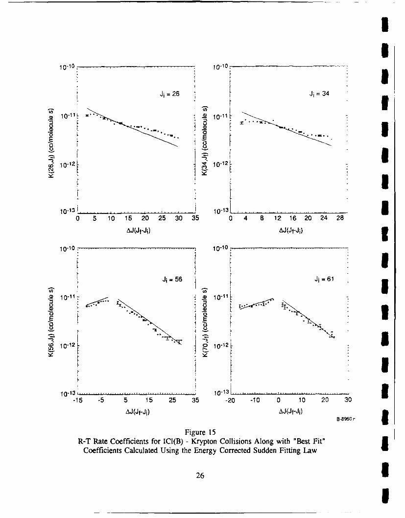
In Figure 13 we present a distribution of R-T rate coefficients for as a function of the Inumber of rotational quanta exchanged in the collision using ICI as the collision partner.Inspection of Figure 13 reveals two distinct regions: a strong peak for small 2J and a muchbroader distribution for larger A. This strong propensity for small 2J is the most striking Ithat we have observed in all of our investigations. In addition the absolute magnitude of thesmall A2 rate coefficients are a large fraction of gas kinetic. Indeed, the sum of iheindividual rate coefficients Cthe rate coefficient for R-T removal from the initially excitedlevel) is on the order of 10-9 cm 3 molecules- I 1. This is a factor of three larger than anyother R-T rate coefficient that we have observed in IF, BrCI, or ICI. We suggest that longrange dipole-dipole interactions from ICI + ICI collisions may be responsible for thisbehavior. The rate coefficients that we have determined for ICI collisions with several bathgases are presented in an Appendix. 5In Figures 14 through 16 we present comparisons of fitting laws to data for ICI collisionswith several bath gases. We note that as the mass of the collision partner increases, thedistribution becomes less peaked about small 2J. This is similar to the behavior that weobserved for IF and is analogous to that reported previously for 12. 16
In Tables 5 and 6 we compare the four fitting laws for boih IF and IC1.
I22 3

0.10
k(56--40) = 9.7 x 10⁻¹² cm 3 molecule- 1 s-1
0.08 -
o 0.06Ln3
z
z0.04-
0.00 !
0 1 2 3 4 5 6 7 8 9[M] x t(molecule cm-3 S x 10-9)
a) Stern-Volmer plot for relaxation from Ji = 56- Ji = 40
0.095 I I I I I 1 1
0.085 -k(56--460) = 7.1 x 10⁻¹² cm3 molecule-1 s-1
0.075
• 0.065U,)z--n 0.055z
0.045
0.035
0.025I I
0 1 2 3 4 5 6 7 8 9
[M] x '(molecule cm- 3 s x 10-9) B-5753
b) Stern-Volmer plot for relaxation from Ji = 56 -. Jf = 60
Figure 12Stern-Volmer Plots for Two State-to-State Processes Using 02 Bath Gas
23

I
10-10rL 10-10~
lo~oi } o~too,St I
E E 0.*
I dPM 10-12 10-12H . * I
10-131 10-13L
-20 0 20 40 60 -30 -10 10 30 so
,Al(Jf - Ji) AJl(Jf - Ji)
10-10 : 10-10 . : _ , ,.. .S" " I
I 0
Q %4
r-:______________ 111 10-132________________
-50 -30 -10 10 30 -50 -30 -10 10 30 5
A•j(Jf - J0) AJ(Jf - Ji)B-8949Figure 13 I
R-T Rate Coefficients for the ICI(B) + ICI System. Data are shown for several J i"244|
r i

10-10 - 10-10
Ji =26 Ji =34
2D 10.'1•- a,• io10 11
0 -
0
CD"
10-12 51015 10-13.
0 5 10 15 20 25 30 35 0 4 8 12 16 20 24 28
-AJ(Jf-Ji) AJ(Jf-J i)
10-10o 10-10o
Ji =56 Ji =70
€• 10-11L A?¢ 10-11..) " "
E E
1 0 -13 ,. . . . . . . . . . . . . . . . . . . . ....... 1 0 -13 . .. . . . . . . . . . . . . . . . . . . .-15 -5 5 15 25 35 -30 -20 -10 0 10 20
A•J(Jf-Ji) AJ(Jf-Ji)8-8952
Figure 14
R-T Rate Coefficients for ICl(B) - Helium Collisions Along with "Best Fit"
Coefficients Calculated Using the Infinite Order Sudden Fitting Law
25
I
10-10. 10-10,
Ji =26 Ji =34
E E
" 0 5 10 15 20 25 3-3.48 1.1 0 4 2
AJ..)Ji *e.fJi
10" . . .....
10-13
I
E E
10-12[ 10-12~
4- 1
10-13L .. ...I01 1 ....-............... .....
0 5 10 15 20 25 30 35 0 4 8 1 16 20 24 28
AJ(Jf-Ji) AJ(Jf-Ji) 3
Ji66
" 1 I
10 -211101k•
I IIlI
-15 -5 5 15 25 35 -20 -10 0 10 20 30
AJ(Jf'Ji) •~J(Jf'Ji)
e85,
Figure 15
Coefficients Calculated Using the Energy Corrected Sudden Fitting Law
26 1
1

I0-10 10-10
Ji =26 Ji =34
-. 10-12, 10-11 '-
CrD
10-1 1 31
AJ(Jf-Ji) AJ(Jf-Ji)
-1-o 10-10-
J=56 Ji 70
:3 10-11 - • 10.
E 4 E
LO10-12 - i ""
- f
10-13 10-1 3
-15 -5 5 15 25 35 -30 -20 -10 0 10 20
AJ(Jf-Ji) AJ(Jf-Ji) B-8951
Figure 16R-T Rate Coefficients for ICI(B) - Xenon Collisions Along With "Best Fit"
Coefficients Calculated Using the Statistical Power Gap Law
27
I
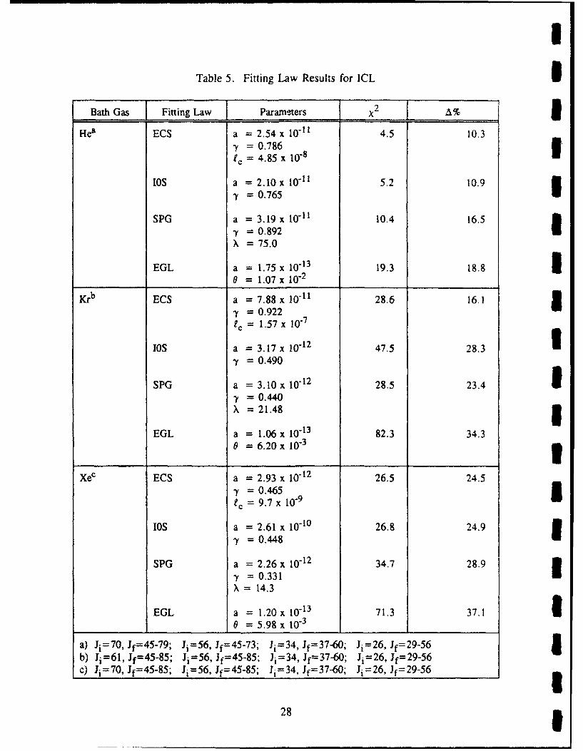
Table 5. Fitting Law Results for ICL SBath Gas Fitting Law Parameters x 2 I,:%
Hea ECS a = 2.54 x 10-"l 4.5 10.3-y = 0.786 1ec =4.85x 10"s8
lOS a = 2.10 x 10-"i 5.2 10.9-y = 0.765 I
SPG a = 3.19 x 10"-1 10.4 16.5"7 0.892 IX 75.0
EGL a = 1.75 x 10⁻¹³ 19.3 18.8 10 = 1.07 x 10⁻²
Krb ECS a = 7.88 x 10⁻¹¹ 28.6 16.1 1y = 0.922ec = 1.57x10- 7
10s a = 3.17 x 10⁻¹² 47.5 28.3 i-y = 0.490
SPG a = 3.10 x 10⁻¹² 28.5 23.4 1-y =0.440X = 21.48 5
EGL a = 1.06 x 10⁻¹³ 82.3 34.30 = 6.20 x 10⁻³
XeC ECS a = 2.93 x 10⁻¹² 26.5 24.5S= 0.465tc = 9.7 x 10⁻⁹
I0S a = 2.61 x 10"I0 26.8 24.9-y = 0.448 I
SPG a = 2.26 x 10⁻¹² 34.7 28.9-y = 0.331 IX 14.3
EGL a = 1.20 x 10⁻¹³ 71.3 37.1 10 = 5.98 x 10⁻³
a) Ji=70, Jf= 4 5-79 ; Ji=56, Jf=45-73; Ji=34, Jf= 3 7 -6 0 ; Ji=26, Jf=29-56 Ib) Ji=61, Jf=45-85; Ji=56, Jf= 4 5-85; Ji=34, Jf=37-60; Ji=26, Jf= 29-56c) 1i=70, Jf=45-85; Ji=56, Jf= 4 5-85; Ji=34, Jf=37-60; Ji=26, Jf=29-56
28 1

Table 6. Fitting Law Results for IF
Bath Gas Fitting Law Parameters X2 %
Hea ECS a = 3.84 x 10⁻¹¹ 8.1 18.4-f = 0.883ic = 8.3 x 10¹²
lOS a = 4.00 x 10"11 7.9 18.7,y = 0.889
9.7 19.1SPG a = 3.27 x 10⁻¹¹
- = 0.918S= 94.3
11.4 21.1EGL a = 1.35 x 10⁻¹³
0 = 3.62 x 10⁻³
Xe6 ECS a = 1.65 x 10⁻¹⁰ 12.4 24.5S= 1.04
1C = 1.0x 10⁷ c
10S a = 6.44 x 10"12 36.6 40.9y= 0.644
SPG a = 6.82 x10- 12 11.5 23.3S= 0.509
X = 11.52
EGL a = 5.39 x 10⁻¹⁴ 49.3 46.80 = 1.82 x 10⁻³
a) Ji=72, Jf=42-78; Ji=27, Jf=30-45; Ji= 13, Jf16-27;b) Ji=72, Jf=42-78; Ji=27,Jf=30-47; Ji=13, Jfl6-41;c) ee fixed at 1.0xl0" cm for this fit.
C.2 ICI optically-pumped laser study.
We constructed an 12 laser to assure that the optical resonator was properly aligned. (Thesame mirrors can be used for both the 12 and the ICI lasers.) Strong laser action on the 12system was readily observed as shown in Figure 17. Excitation was on the (14, 0) band.The excitation spectrum was obtained by monitoring the 12 laser output as a function of dyelaser excitation wavelength.
In Figure 18 we show a similar scan using ICI as the active medium. While these datashould be considered preliminary there are clear differences between the two spectra. Inorder to minize contamination caused by 12, we tried several ICI sources. For example, wesubjected a sample of ICI to numerous freeze/thaw cycles. We also used IC13 crystals as thesource. This is the same approach that we use in the ring laser ICI RET studies.
29

U4.5 1
4
.E 3>
-Zi2.5
'23
~1.5I
1
0.51
0 j577.8 578 578.2 578.4 578.6
Laser Wavelength (nm)
Figure 17 3Laser Excitation Spectrum Using 12 as the Active Medium.
0.11 I0.1
0.09 5--- 0.08
S0.07w 0.06
-0. 0 5C
0.03
0.02 '0.01
0 t .. . . . .577.8 578 578.2 578.4 578.6 I
Laser Wavelength (nm) B-423
Figure 18 1Laser Excitation Spectrum Using ICI as the Active Medium.
30 £8

Although this reduced the 12 contamination strong 12 LIF signals were still observed. Part orthe problem is the rather wide bandwidth of the pulsed dye laser (0. 1 cm' 1 ). Consequently,it may be difficult to excited isolated lines of ICI in the presence of even trace amounts of 1,and weak ICI lasing could be unobservable in the presence of 12 laser. In contrast, we havealready demonstrated that the ring dye laser is capable of exciting a single ICI absorptionfeature. Thus the ring dye laser might serve as an attractive excitation source for an ICIlaser. Due to programmatic desires of the Air Force, we focused most of our attention forthe remainder of the contract on overtone-pumped lasers, and were unable to attempt the CWoptically-pumped laser experiments on ICI. We feel that this would be a fruitful set ofexperiments to try.
Nevertheless, our preliminary data indicate that we may have succeeded in demonstrating apulsed ICI (B--*X) laser. The key point is that lasing is observed at excitation wavelengthsdistinct from those for 12.
C.3 04 dimole laser support.
In an effort to examine further the emission spectra reported by Yoshida et al.20 we haveused our spectral simulation code to predict the C12 (B--X) emission system for a variety ofconditions. In Figures 19 through 23 we present some of these results. The two parameters
, that we varied were: a) vibrational distribution the B state and b) the resolution element tomimic the instrumental response of the monochromator used by Yoshida. 20 These syntheticspectra show that the observed emission is a sensitive function of both the instrumentalbandwidth and the initial vibrational distribution. It is of interest and perhaps significant thatthe spectra observed by Yoshida is qualitatively similar to our C12 (B-.X) spectrum. Whilethis certainly does not confirm the emission originating from C12 , is it suggestive that thechemiluminescence may be from species other than 04
1.00
.'0.80
_- 0.60
p0.40
0.20
0520 570 620 670 720 770 820 870
Wavelength (nm) 64241
Figure 19Synthetic C12 (B-.X) spectrum. 10 nm Resolution; TR Tvib = 300 K
31

I100
0.80
E 0.60V0.40 1
z I0.20 1520 570 620 670 720 770 820 870
Wavelength (nm) B Q42
Figure 20 ,Synthetic C12 (B-X) Spectrum. 10 nm resolution; relative vibrational
distribution as follows: v' 0 1, v'= 1, v' 2 = 1, v 3 = 1, v'4 =
1.00
0,80 39 0,60
0,40
z0.20
0520 570 620 670 720 770 820 870
Wavelength (nm) 8 424
Figure 21 1Synthetic C12 (B-*X) Spectrum. 10 nm resolution; relative vibrational
distribution as follows: v' 0 = 0.33, v' 1 = 0.66, v' 2 = 1.0, v' 3 = 0.66, v' 4 0.33
1.00
0.80
0.4
z 0.20
0,1520 570 620 670 720 770 820 870
Wavelength (nm) 8 4
Figure 22 ISynthetic Cl2 (B--X) Spectrum. 15 nm resolution;
vibrational distributions same as for Figure 21
32

1,00
.2,0.80
E 0.60
CO 0.40
0z0.20
0520 570 620 670 720 770 820 870
Wavelength (nm) B-4245
Figure 23Synthetic C12 (B--X) Spectrum. 20 nm resolution;
vibrational distributions same as for Figure 21
C.4 Vibrational relaxation in IF(X).
In Figure 24 we present data showing the decay of IF(X,v=9) in the fast flow reactor. We haveplotted ln[lF(X,v =9)]t=0/ln[IF(X,v =9)]t as a function of the reaction time. These data werefor a 2/1 mix of helium and argon at a concentration of 0.65 Torr. From these data we estimatethat the V-T relaxation rate is -6 x 10-14 cm 3 molecule-1 s-1. These preliminary estimatesindicate that relaxation is extremely slow. Thus, IF(X,v) may be a robust energy reservoir.
0 U
-1
"r -2C
U-3
-4
0 0.002 0.004 0.006 1.008Reaction Time (s) C.2331
Figure 24Decay of IF(X,v=9) in Presence of 2/1 Helium/Argon Mix at a Pressure of 0.65 Torr.
33

C.5 Optically-pumped overtone HF laser. IIn Figure 25 we present an absorption spectrum for several rotational lines in the HF(2,0)overtone band. These data were obtained by monitoring the Raman shifted dye laser outputthat was transmitted through the cell that contained HF gas. Also shown in Figure 25 aredata obtained by increasing the pump power of the Raman shifted dye laser. The strongemission features are due to amplified spontaneous emission (ASE). These data wereobtained in the 7.5 cm cell that contained 50 Torr of HF and 670 Torr of helium. Thefeatures appear sharper than the absorption lines because there is a threshold power level forASE.
The pump intensity threshold for .,,e ASE was quite low as indicated in Figure 26. Thesedata obtained in the 7.5 cm cell c. .,aining 50 Torr of HF indicate a threshold energy of lessthan 100 uJ. Since this was for a mirrorless cell with no feedback, we estimate that in acavity, less than 10y•J of pump excitation will be required.
We found that the ASE output power was independent of added helium bath gas as indicatedin Figure 27. This is an encouraging result since the addition of a collisional bath gas willUbroaden the overtone absorption line. This may enhance the coupling of pump lasers into thelaser media. g
0.9 R2(7)
0.8 fl2(6)AbsorptionII 0.7 - 25 Torr R2(5)
~0.6 Uj-e~
0.3 R2 40 0.4 ASE Sz •-ASE
0.1 R2(3 R2(2) :2(1
W , I I I _ j1.25 1.254 1.258 1.262 1.266 1.27 1.274 1.278 3
Excitation Wavelength (pm) B.9o6o
Figure 25 3Absorption Spectra and Corresponding ASE Spectra for Overtone-pumping Several R-branchLines on the HF(2,0) Overtone Band. The top spectrum shows absorption of the dye laserand the bottom trace shows the ASE excitation spectrum. The two spectra have been offset i
slightly for clarity.
34 1I

1.1 I !
1 - )3
7.5cmCeoll0.9 HF 50 Torr
0
0.8 -0
ra 0.7 -00
-- 0.6 -
o0.5 -E
Z 0.4 -a
0.3 -
0.2-0
0.1 -0I t I I i !
0 0.2 0.4 0.6 0.8 1 1.2 1A4 1.6 1.8
Laser Energy (mJ) 8-9073
Figure 26I ASE Output as a Function of Pump Energy Incident on the Cell.
The R(3) line of v =2 in HF was excited for thes&' data.S1.1 ! ! i I I
0 C 0 E 0
I -3 (3 oo
Io.. 0.9
0.8l o0.7-
S0.6 -
1_-U 0.5-EC 0.4 -
S0.3 -
0.2 - (HF] 50 Torr
I0.1 - 7.5 crm Coll
0,1 LIII0 I l I II ! I l
0 2 4 6 8 10 12 14 16 18 20
(He] (1018 cm -3) 9-9072
Figure 27Output of HF ASE as a Function of Added Helium. The R(3) line in v=2 was pumped.
L 35

I
We also found that the ASE was quite insensitive to the HF concentration. In Figure 28 we 5present data that were obtained pumping the R(3) line with 2 ml of excitation incident uponthe cell. There is an initial rise as the concentration increased from 0 to about 100 Torr.As more HF is added collision deactivation of the optically pumped level begins to exceed Ithe excitation rate and the output energy drops. These data however indicate that the HFovertone-pumped laser is quite immune to self quenching. 3VWe also performed some experiments in which the output of the ASE was spectrallyresolved. These experiments provide important insights into the energy pathways and energytransfer within the excited state manifolds. For these experiments we placed a 0.3m Imonochromator in front of the InAs detector. Some typical data are presented in Figure 29.
For clarity, both the observed spectra and the associated energy levels are presented inFigure 29. These data illustrate an important feature of the overtone-pumped HF laser. Wepumped the P(2) line of the (3,0) band near 875 nm. We observe ASE from both rotationaland vibrational levels distinct from the level initially excited by the dye laser. Indeed,rotational relaxation in the initially pumped v=3 level is evident. From a practicalperspective our observation of ASE from both the (3,2) and (2,1) bands indicates cascading Ilaser emission. Thus one may be able to recover a large fraction of the initial photons thatwere absorbed by the medium. These experiments should be repeated using an opticalresonator. Nevertheless, these initial measurements are very encouraging.
00 7.5 cm Cell0 Laser Energy 2.0 mJ/pulse0.9 - a
0
0.5
0.4
0.3
0.2
0.1II ,
0 2 4 6 8 10 12 14
[HF] (1018 cm-3) .g071 IFigure 28
ASE Signal Strength as a Function of Added HF.The R(3) line in the (2,0) band was excited for these data.
36 1I

II
Excitation was on P(2) of the (3,0) bandI (Energy levels involved are indicated)
V - 37I::•
0.1 . . .. . . .. . .P( 4 )i \PP(3)
110 cm cell i 20.08 9.7 torr F P( (3,2)
I0.0 f•2 )Excitation •
P(4)
i = 0.04 P(2) (3,2)
~uJ 0.023 P(4) (2,1) V-I ____
I < P(4) (3,2)
2550 2650 2750 2850 2950Wavelength (nm)
C-332V 0v-o 3
Figure 29i Spectrally Resolved HF ASE Output Following Excitation of v =3.
An eventual gas phase overtone-pumped laser might be excited by a tunable diode laser. Inan initial attempt to demonstrate the potential of this approach, we used a low power (2mW)heterostructure near infrared diode laser Io probe a cell of HF. Strong absorption wasobserved when the dye laser was tuned to the P(3) line of the (2,0) band near 1.26 microns.In Figure 30 we show data using the 7.5 cm cell filled with 9 Torr of HF. The absorptionapproaches 90% as expected from the strong overtone absorption cross sections. Thepotential for using a high power diode laser to produce an optically-pumped HF laser isapparent, and we will pursue this approach in our follow on effort.
I ~Summay
We have described the results of a program that has examined energy transfer in severalsystems. In addition, we have discussed applications to several Air Force programs. Inparticular we focussed our attention in year three on near-IR lasers, an emerging Air Forceneed. We will explore these concepts further in our follow-on program.
37

I1.0
0.8 5°I I,. 0.61
.2
~0.IE
0.4
0.0 30 0.1 0.2 0.3 0.4 0.5 0.6
Scanwidth (cm-1) C-0024a
Figure 30
Absorption Spectrum of HF P(3) on the (2,0) band.The 7.5 cm cell contained 9 Torr of HF.
ReferencesI
1. Davis, S.J., and Holtzclaw, K.W., "Rotational Energy Transfer in Excited States of
Halogen Molecules, I. Transfer from v'=6, J'=72 in IF B31"(0+), J. Chem. Phys.,92, 1661 (1990).
2. Wolf, P.J., and Davis, S.J., "Collisional Dynamics of the IF B3 Hl(0+) State. II. IElectronic Quenching at Low Pressures", J. Chem. Phys., 83, 91 (1985).
3. Wolf, P.J., and Davis, S.J., "Collisional Dynamics of the IF B3 fl(0+) State. III. IVibrational and Rotational Energy Transfer", J. Chem. Phys., 87, 3492 (1987).
4. Girard, B., Billy, N., Gouedard, G., and Vigue, J., J. Chem. Phys., 88, 2342 1(198:). M.A.A., and M-Dermid, I.S., "Quantum-resolved Dynamics of Excited
States, anrt 4. Radiative and Predissociative Lifetimes of IF B3 11(0+).", 3. Chem.Soc., Far. Trans. II, 4, 1644 (1978). 1
38 1I

6. Kitimura, M., Kondow, T., Kuchitsu, K., Munakata, T., and Kasuya, T.,"Fluorescence Lifetimes and Spontaneous Predissociation of 135C1 (BO+, v' = I and 2)as studied by Laser excited fluorescence", J. Chem. Phys., 82, 4986 (1985).
7. Clyne, M.A.A. and McDermid, I.S., B3,1(0+) States of IF, ICI, and IBr Part 1.Calculation of the RKR Turning Points and Franck-Condon Factors for the B-XSystems", J. Chem. Soc. Faraday Trans. II, 73, 1094 (1977).
8. Gordon, R.D. and Innes, K.K., "Predissociations in the B3IO+ State of 135C1 and137C1., j. Chem. Phys., 71, 2824 (1979).
9. Trickl, T. and Wanner, J., "High-Resolution, Laser-Induced FluorescenceSpectroscopy of Nascent IF: Determination of X- and B-State Molecular Constants",J. Mol. Spect., 104, 174 (1984).
10. Brand, J.C.D. and Hoy, A.R., "High Vibrational Levels of the X State of ICI, andthe Electronic-Coriolis Coupling of the X and A States", J. Mol. Spect., 114, 197(1985).
11. Brunner, T.A. and Pritchard D., "Fitting Laws for Rotationally Inelastic Collisions",Dynamics of the Excited State, Ed. K.P. Lawley, pp. 589-641, John Wiley & Sons.Ltd., New York, 1982.
12. Steinfeld, J.I., and Ruttenberg, P., "Scaling Laws for Inelastic Collision Processes inDiatomic Halogens", JILA Information Center Report No. 23, (1983).
13. Brunner, T.A., Smith, N., Karp, A.W., and Pritchard, D., "Rotational EnergyTransfer in Na2 (A2E) Colliding with Xe, Kr, Ar, Ne, He, H2, CH 4 , and N2 :Experiment and Fitting Laws", I. Chem. Phys., 74, 3324 (1980).
14. Polanyi, J.E. and Woodall K.B., "Mechanisms of Rotational Relaxation", J. Chem.Phys., 56, 1563 (1972).
15. Brunner, T.A., Driver, R.D., Smith N., and Pritchard, D., "Simple Scaling Law forRotational-Energy Transfer in Na2*-Xe Collisions", Phys. Rev. Lett., 41, 856 (1978).
16. Dexheimer, S.L., Durand, M., Brunner, T.A., and Pritchard D.E., "DynamicalConstraints on the Transfer of Angular Momentum in Rotationally Inelastic Collisionsof 12(B3-r(0+) with He and Xe", J. Chem. Phys., 76, 4996 (1982).
17. DePristo, A.E., Augustin, S.D., Ramaswamy, R., and Rabitz, H., "QuantumNumber and Energy Scaling for Nonreactive Collisions", J. Chem. Phys., 71, 850(1979).
39

I
18. Scott, T.P., Smith, N., and Pritchard D.E., "Application of Fitting Laws to 5Rotationally Inelastic Rate Constants: Li2*(alsigma) + Ne, Ar, Xe", J. Chem.Phys., 80, 4841 (1984). 1
19. Bevington, P.R., Data Reduction and Error Analysis for the Physical Sciences,McGraw-Hill, New York, 1969.
20. Yoshida, S., Shimizu, K., Sawano, T., Tokuda, T., and Fujioka, T., Apply. Phys.Lett. 54, 24 (1989). 5
21. Davis, S.J. and Woodward, A.M., "Excitation of IFB(3QO+) by Metastable 02. 1.Studies Involving IF(X,v)". J. Phys. Chem. 95, 2429 (1991). 3
22. Trick], T. and Wanner, J. J. Chem. Phys. 78 6091 (1983). 1
4
IIIIIIII
40 1I

Appendix
Summary of Rate Coefficients Measured for ICI Collisions with Several Bath Gases
Initially populated levels (J1) are indicated. Rate coefficients (k (Ji, Jf)) and standarddeviations (a) determined from Stem-Volmer plots are tabulated.
41

I
Table A-1. Rate Coefficeints for ICI + He Collisions i= I II
ICI + He (Ji = 26, vi=I) ICI + He (Ji = 26, vi =1)
(10-12 cm 3 molecule' 1 s-1 ) (10-12 cm 3 molecule 1 si)
Jf k(Ji,Jf) Jf k(Ji,Jf)
20 12.6 1.3 58 1.2 0.2 321 11.8 0.5 59 0.8 0.222 14.5 1.3 60 1.0 0.223 14.9 1.0 61 0.8 0.124 15.0 1.7 62 0.7 0.125 15.7 1.0 63 0.9 0.126 0.0 0.0 64 0.9 0.127 11.3 1.5 65 0.7 0.128 20.2 1.4 66 0.7 0.129 16.6 0.530 15.1 0.731 13.6 0.732 12.3 0.833 11.4 0.534 10.3 0.435 9.3 0.436 8.9 0.5 I37 5.8 0.438 6.6 0.339 5.6 0.340 5.4 0.341 4.9 0.442 4.9 0.243 4.7 0.244 4.5 0.245 4.2 0.446 4.4 0.347 3.4 0.148 3.6 0.2 I49 3.0 0.250 3.1 0.151 2.8 0.1 I52 2.4 0.153 2.2 0.154 1.7 0.255 1.9 0.256 1.5 0.157 1.6 0.1 3
I42
I

Table A-1. Rate Coefficeints for ICI + He Collisions (Continued)
ICI + He (Ji = 34, vi=1) ICI + He (Ji = 34, vi1)
(10-12 cm 3 molecule-I s-1) (10-12 cm3 molecule-' s-1 )
Jf i(Ji,Jf) or if k(Ji,Jf) a
27 18.4 0.6 68 0.8 0.128 13.7 0.8 69 0.8 0.129 13.7 0.7 70 0.7 0.130 15.7 0.6 71 0.7 0.131 16.0 0.9 72 0.6 0.132 17.5 0.8 73 0.7 0.133 12.5 1.0 74 0.3 0.134 0.0 0.035 17.9 0.936 12.8 1.137 15.4 0.738 13.6 0.639 12.6 0.640 11.5 0.441 10.4 0.542 9.6 0.343 8.8 0.344 7.9 0.245 7.7 0.346 5.5 0.247 5.2 0.248 4.7 0.249 4.3 0.150 4.4 0.151 4.2 0.152 3.8 0.153 3.5 0.154 3.0 0.255 3.3 0.156 3.1 0.157 2.7 0.158 2.6 0.259 2.8 0.260 2.5 0.161 1.8 0.162 1.9 0.263 1.5 0.164 1.3 0.165 1.3 0.166 1.2 0.167 0.9 0.1
43

Table A-1. Rate Coefficeints for ICI + He Collisions (Continued) 5ICI + He (Ji 56, vi=1) ICI+ He (J, = 56. v'i=1) I
(10- 12 cm 3 molecule-1 s-1) (10- 1 2 cm 3 molecule"1 s 1 )
Jf k(JiJf) i o" Jf k(Ji,Jf) a 322 3.1 (0.3) 62 (0.3)23 1.8 (0.3) 63 (0.3)24 2.2 (0.4) 64 (0.2)25 1.7 (0.3) 65 6.3 (0.1)26 2.6 (0.3) 66 5.1 (0.2)27 3.6 (0.4) 67 4.8 (0.3) u28 2.1 (0.6) 68 5. 1 (0.2)29 4.7 (0.3) 69 3.7 (G.30 4.2 (0.3) 70 3.5 (0.2) I31 4.0 (0.5) 71 3.4 (0.2)32 4.3 (0.3) 72 2.9 (0.2)33 4.3 (0.3) 73 2.9 (0.2) I34 5.0 (0.2) 74 3.7 (0.2)35 4.8 (0.3) 75 2.5 (0.2)36 5.2 (0.4) 76 1.9 (0.1) I37 5.4 (0.5) 77 2.2 (0.1)38 5.6 (0.3) 78 1.5 (0.1)39 5.8 (0.5) 79 1.9 (0.2) I40 5.8 (0.3) 80 1.5 (0.2)41 5.7 (0.3) 81 0.7 (0.1)42 5.8 (0.2) 82 1.2 (0.1) •43 6.2 (0.3) 83 1.4 (0.1)44 6.3 (0.4) 84 1.0 (0.1)
45 8.2 (0.4) 85 1.0 (0.2)46 8.9 (0.4) 86 1.1 (0.2)47 9.1 (0.3)48 10.5 (0.3)49 10.7 (0.5)50 11.9 (0.6)51 13.3 (0.5)52 13.4 (0.7)53 15.2 (0.6)54 16.4 (0.5)55 12.2 (0.6)56 0o0 (0.0)57 12.1 (0.5)58 16.0 (0.9)59 13.7 (0.7)60 11.6 (0.5)61 10.5 (0.4) !1
THE TCOTAL RELAXATION RATE OUT OF J 56: K(TOT)= 3.8368E-10
44
I

Table A-I. Rate Coerttieints fur [C0 + He Collisions (Continued)
ICI + He (Ji = 70, vi'=1) ICI + He (Ji = 70, vi'=1)
(10-12 cm3 molecule-1 s"1 ) (10-12 cm 3 molecule-1 s')
Jf k(Ji'jf) a Jf k(Ji,Jf) o"
31 1.9 0.9 71 13.4 0.832 2.4 1.1 72 16.8 1.133 1.7 0.5 73 13.4 0.534 2.3 0.8 74 11.4 1.4
35 2.4 0.8 75 10.2 0.7
36 0.9 1.0 76 10.5 1.7
37 3.0 1.1 77 7.8 0.4
38 2.4 0.5 78 8.5 0.5
39 2.8 0.7 79 6.1 1.240 0.8 1.0 80 4.5 0.641 2.7 0.8 81 3.1 0.842 3.7 0.5 82 7.9 1.043 3.1 0.6 83 5.9 1.044 3.4 1.1 84 6.1 0.845 4.0 0.6 85 3.8 0.846 4.2 0.6 86 2.1 0.947 3.6 0.8 87 2.0 0.448 5.1 1.1 88 1.4 0.6
49 4.6 1.1 89 1.3 0.5
50 4.8 0.8 90 0.8 0.351 4.6 0.652 6.2 0.7
53 5.9 0.654 5.1 0.855 5.1 0.856 5.9 0.457 5.0 0.558 6.9 0.659 7.3 0.460 8.6 0.661 10.1 1.162 6.4 1.163 11.3 1.164 9.4 0.765 12.5 1.266 10.3 0.867 13.5 1.168 14.6 1.269 13.4 1.070 0.0 0.0
45

I
Table A-2 Rate Coefficients for ICI + Kr Collisions I
ICI + Kr (Ji = 26, vi=1) ICI + Kr (Ji = 26, v =1)
(10-12 cm 3 molecule-1 s-1) (10"1 2 cm 3 molecule"1 s-1 )
if k(Ji,jf) a Jf k(Ji,Jf) a
20 10.9 0.8 61 2.6 0.121 9.9 0.5 62 2.7 0.122 10.9 0.6 63 2.4 0.123 9.8 0.6 64 2.2 0.124 10.5 1.2 65 2.1 0.1 325 11.4 1.0 66 2.1 0.126 0.0 0.027 12.0 1.928 14.0 0.529 10.1 0.330 10.8 0.431 10.8 0.432 10.3 0.533 9.4 0.334 8.9 0.335 8.4 0.336 7.9 0.637 6.9 0.2 I38 7.4 0.339 7.1 0.240 6.4 0.2 I41 6.0 0.242 6.2 0.143 6.0 0.144 5.9 0.145 6.0 0.346 5.6 0.1 347 5.3 0.148 4.9 0.149 5.0 0.150 4.8 0.151 4.5 0.052 4.2 0.053 4.0 0.054 3.9 0.155 3.6 0.1 356 3.5 0.157 3.5 0.158 3.3 0.159 3.1 0.160 2.7 0.1
46 i

I
Table A-2 Rate Coefficients for ICI + Kr Collisions
iCl+ Kr i = 34, vIC + Kr (li = 34, vi)
(10-12 cm3 molecule-' s") (10-12 cm 3 molecule"I s-1)__________~~~ , t C r(~ = 3,,,,,,
Jf k(Ji,Jf) a_ if k(Ji,Jf) a 1.....
27 16.1 0.5 68 2.0 0.1
28 11.1 0.3 69 2.0 0.129 8.7 0.3 70 1.8 0.130 9.1 0.3 71 1.7 0.1
31 8.6 0.5 72 1.5 0.1
32 7.3 0.7 73 1.3 0.133 3.3 1.2 74 1.2 0.134 0.0 0.035 6.6 0.536 3.4 0.337 7.2 0.4
38 8.3 0.439 7.6 0.3
40 7.7 0.241 7.5 0.342 7.3 0.243 7.1 0.244 7.0 0.245 8.0 0.246 6.3 0.247 5.8 0.148 5.8 0.249 5.4 0.250 5.4 0.151 5.1 0.152 4.7 0.153 4.4 0.154 4.0 0.155 4.1 0.156 3.9 0.157 3.9 0.158 3.9 0.159 3.8 0.160 3.3 0.161 3.0 0.162 3.0 0.163 2.6 0.164 2.5 0.165 2.4 0.166 2.3 0.167 2.1 0.1
47

I
Table A-2 Rate Coefficients for ICI + Kr Collisions (Continued) iICI + Kr (J i = 56, v i~ .. ICI + Kr (Ji = 26, vi =1)
(10-12 cm3 molecule-1 s-1) (10-12 cm 3 molecule-1 s- )
Jf k(J ,Jf) 1.a J.......... k(J ,Jf) a.......
17 6.4 0.6 56 0.0 0.018 4.9 0.5 57 6.5 0.419 5.6 0.4 58 7.6 0.520 6.6 0.5 59 6.8 0.321 5.8 0.3 60 6.2 0.3 U22 6.5 0.3 61 6.1 0.2
23 5.4 0.5 62 5.2 0.224 4.9 0.4 63 4.6 0.2 I25 4.8 0.4 64 4.9 0.126 3.7 0.5 65 4.5 0.227 4.6 0.4 66 4.3 0.328 4.5 0.4 67 3.9 0.329 4.0 0.3 68 3.9 0.230 5.0 0.3 69 3.4 0.1 331 5.5 0.4 70 3.3 0.332 6.2 0.3 71 2.7 0.133 6.3 0.2 72 2.9 0.! 334 7.4 0.4 73 2.2 0. 135 7.6 0.4 74 2.1 0.136 6.9 0.3 75 1.7 0.237 7.0 0.3 76 1.7 0.238 6.8 0.3 77 1.5 0.239 6.6 0.5 78 1.5 0.140 6.4 0.3 79 1.4 0.1 U41 6.0 0.2 80 1.5 0.142 6.2 0.4 81 1.3 0.243 5.5 0.2 82 1.2 0.1 I44 5.9 0.4 83 1.3 0.145 6.5 0.2 84 1.2 0.146 6.5 0.3 85 1.3 0.1 I47 6.7 0.2 86 0.8 0.148 7.1 0.249 6.9 0.4 I50 7.7 0.251 8.1 0.452 8.2 0.4 U53 8.3 0.354 8.3 0.455 6.9 0.6 I
48 I
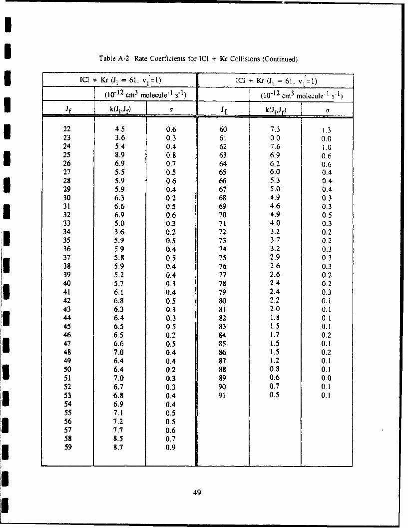
Table A-2 Rate Coefficients for ICI + Kr Collisions (Continued)
3OC + Kr (Ji = 61, vi=l) ICI + Kr (Ji =61, vi=l)
(10-12 cm 3 molecule'l s1) (10-12 cm 3 molecule-1 s-1)
If k(Ji,Jf) a Jf k(Ji,J) La
22 4.5 0.6 60 7.3 1.323 3.6 0.3 61 0.0 0.024 5.4 0.4 62 7.6 1.025 8.9 0.8 63 6.9 0.626 6.9 0.7 64 6.2 0.627 5.5 0.5 65 6.0 0.428 5.9 0.6 66 5.3 0.429 5.9 0.4 67 5.0 0.430 6.3 0.2 68 4.9 0.331 6.6 0.5 69 4.6 0.332 6.9 0.6 70 4.9 0.533 5.0 0.3 71 4.0 0.334 3.6 0.2 72 3.2 0.235 5.9 0.5 73 3.7 0.236 5.9 0.4 74 3.2 0.337 5.8 0.5 75 2.9 0.338 5.9 0.4 76 2.6 0.339 5.2 0.4 77 2.6 0.240 5.7 0.3 78 2.4 0.241 6.1 0.4 79 2.4 0.342 6.8 0.5 80 2.2 0.143 6.3 0.3 81 2.0 0.144 6.4 0.3 82 1.8 0.145 6.5 0.5 83 1.5 0.146 6.5 0.2 84 1.7 0.247 6.6 0.5 85 1.5 0.148 7.0 0.4 86 1.5 0.249 6.4 0.4 87 1.2 0.150 6.4 0.2 88 0.8 0.151 7.0 0.3 89 0.6 0.052 6.7 0.3 90 0.7 0.153 6.8 0.4 91 0.5 0.154 6.9 0.455 7.1 0.556 7.2 0.557 7.7 0.658 8.5 0.759 8.7 0.9
49

I
Table A-3. Rate Coefficients for ICI + Xe Collisions I
ICI +Xe (J, = 26, v=1) ICI + Xe (Ji = 26, vi 1)
(10-12 cm3 molecule-1 s-1 ) (10-12 cm3 molecule- t s-1)
if k(Ji'Jf) a Jf k(JiJf) J I
18 7.6 1.4 55 3.4 0.119 8.2 1.0 56 3.5 0.220 8.9 0.6 57 3.4 0.121 8.8 0.5 58 3.1 0.122 9.4 0.6 59 3.0 0.1 I23 9.6 0.4 60 2.7 0.124 10.8 0.5 61 2.5 0.125 11.3 1.3 62 2.3 0.126 0.0 0.0 63 2.3 0.127 10.7 0.8 64 2.2 0.128 9.6 0.5 65 1.9 0.129 10.3 0.3 66 1.9 0.130 9.6 0.331 9.3 0.332 9.0 0.333 8.4 0.134 8.1 0.135 7.6 0.136 7.2 0.137 7.0 0.338 6.3 0.239 6.8 0.240 6.3 0.241 6.4 0.1 I42 6.1 0.143 5.9 0. i44 6.0 0.3 345 5.3 0.346 5.3 0.247 4.9 0.1 548 4.7 0.149 4.5 0.150 4.3 0.1 i51 4.2 0.152 4.0 0.153 3.9 0.1 354 3.5 0.1
50I I

Table A-3. Rate Coefficients for ICI + Xe Collisions (Continued)
ICI +Xe (Ji = 34, vi=1) ICI + Xe (Ji = 26, vi=1)
(10-12 4.m3 molecule-1 s-1 ) (10-12 cm 3 molecule-, s-1 )
Jf k(Ji,Jf) __ Jf k(Ji,Jf) a
27 14.7 0.4 65 2.3 0.128 11.8 0.4 66 2.2 0.129 9.3 0.4 67 2.0 0.130 9.2 0.3 68 1.9 0.131 9.3 0.3 69 1.7 0.132 8.6 0.3 70 1.7 0.1
33 7.7 0.9 71 1.5 0.134 0.0 0.0 72 1.5 0.135 11.7 0.5 73 1.2 0.136 4.8 0.3 74 1.0 0.137 7.0 0.238 8.3 0.339 7.7 0.340 7.6 0.241 7.5 0.442 7.2 0.243 7.1 0.244 6.9 0.145 7.8 0.246 6.3 0.247 5.5 0.148 5.2 0.249 5.2 0.150 5.1 0.151 4.9 0.152 5.7 0.253 4.2 0.354 3.9 0.155 4.0 0.156 4.2 0.157 4.0 0.258 3.6 0.159 3.2 0.260 2.9 0.161 2.9 0.162 2.9 0.163 2.7 0.164 2.7 0.1
51

I
Table A-3. Rate Coefficients for ICI + Xe Collisions (Continued) iICI + Xe (Ji = 56, vi'=1) ICI + Xe (Ji,= 56, v =1)
(10-12 cm3 molecule-' s-1) (10-12 cm3 molecule-' s-1)
I k{(ijf) If k(Ji,Jf)C 317 7,7 0.4 56 0.0 0.018 9.3 0.7 57 3-8 0.5 I19 9.3 0.7 58 6.4 0.420 9.4 0.7 59 67 0221 9.3 0.6 60 7.3 0.222 11.2 0.7 61 7,2 0.223 8.0 0.4 62 6.6 0.324 6.4 0.5 63 6.6 0.325 6.3 0.6 64 6.2 0.226 6.4 0.4 65 5.7 0.227 6.1 0.5 66 5.3 0.328 6.7 0.4 67 5.4 0.229 8.3 0.5 68 4.7 0.230 6.7 0.4 69 4.2 0.331 7.9 0.5 70 4.0 0.332 10.0 0.5 71 3.6 0.233 11.4 0.6 72 3.3 0.134 10.6 0.4 73 3.6 0.2 I35 11.6 0.4 74 2.7 0.236 11.7 0.4 75 2.6 0.237 I0.8 0.4 76 2.6 0.238 11.0 0.2 77 2.4 0.239 11.2 0.4 78 2.6 0.240 10.2 0.3 79 1.9 0.1 I41 9.1 0.4 80 2.0 0.142 8.7 0.2 81 1.7 0.143 8.5 0.4 82 1.7 0.144 9.3 0.3 83 1.6 0.245 9.6 0.3 84 1.2 0,246 8.9 0.4 85 1.2 0.2 I47 9.4 0.2 86 1.0 0.248 9.6 0.149 9.7 0.3 I50 9.8 0.251 10.2 0.352 9.9 0,3 I53 9.0 0.354 7.3 0.3
I15 4.4 0.4
52 U

I
I Table A-3. Rate Coefficients for ICI + Xe Collisions (Continued)
ICI + Xe (Ji = 70, vi=1) ICI + Xe (Ji = 70, v 1)
(10-12 cm 3 molecule-1 s- 1) (10-12 cm 3 molecule-I s-l)
if k(Ji,Jf) ar if k(JiJf) o
31 6.9 0.8 68 6.1 0.832 7.9 0.6 69 4.2 0.733 7.8 0.8 70 0.0 0.034 11.1 1.0 71 5.0 0.535 8.7 1.0 72 6.3 0436 8.9 0.4 73 7.1 0.437 9.9 0.4 74 6.0 0.438 9.8 0.5 75 5.1 0.539 8.8 0.7 76 6.0 0.440 8.6 0.7 77 4.5 0.341 8.0 0.4 78 5.7 0.542 6.9 0.3 79 3.0 0.543 7.4 0.5 80 4.6 0.344 8.3 0.5 81 3.1 0,345 8.8 0.4 82 2.6 0.646 6.9 0.5 83 1.7 0.347 8.1 0.4 84 2.6 0.448 7.4 0.4 85 2.1 0.349 7.2 0.5 86 1.5 0.250 9.0 0.5 87 2.0 0.351 9.6 0.4 88 0.7 0.452 9.6 0.7 89 1.4 0.553 8.4 0.5 90 0.4 0.1j 54 8.5 0.555 7.7 0.356 8.1 0.5
I 57 10.2 0.558 8.2 0.459 7.2 0.360 8.0 0.761 7.9 0.362 6.5 0.863 6,7 0.364 6.3 0.465 6.7 0.666 7.3 0.667 7.9 0.7
II 53

Table A-4. Rate Coefficients for ICI + ICI Collisions i
ICI + ICI (Ji = 35, vi 1 ) ICI + ICI (Ii = 35, vi=1)
(10"12 cm 3 molecule"1 s- 1) (10- 12 cm 3 molecule-1 s-1)
if k(JiJfp a J if k(J1,Jf I_ I27 14.7 3.4 67 3.8 0.328 20.3 0.9 68 3.8 0.329 23.7 1.3 69 3.1 0.330 23.8 1.0 70 3.0 0.231 27.4 1.7 71 2.5 0.1 332 34.1 1.2 72 2.2 0.233 45.9 1.2 73 1.4 0.334 70.7 2.5 74 1.2 0.235 0.0 0.0 75 1.2 0.236 71.1 2.7 76 1.5 0.237 37.7 1.0 77 1.4 0.138 28.5 0.8 78 1.4 0.2 I39 20.8 0.9 79 1.3 0.140 17.5 0.9 80 1.4 0.241 15.2 0.9 81 1.0 0.142 10.5 1.0 82 1.0 0.243 12.9 0.5 83 1.3 0.244 12.3 0.5 84 1.1 0.2 345 11.9 0.546 11.3 0.447 12.0 0.5 348 9.2 0.549 8.3 0.650 10.0 0.4
51 10.2 0.452 8.3 0.253 7.8 0.254 7.5 0.255 7.0 0.256 6.1 0.257 6.2 0.458 5.2 0.459 3.1 0.660 4.6 0.461 4.8 0.462 5.0 0.363 4.5 0.264 3.5 0.4A 3.9 0.3
66 3.8 0.2
54 I

Table A-4. Rate Coefficients for ICI + ICI Collisions (Continued)
ICI + ICI (Ji = 57, vi=1) ICI + ICI (Ji = 57, vi =1)
(10-12 cm 3 molecule- t s-1 ) (10-12 cm 3 molecule-1 s-1 )
Jf k(Ji,Jf) aJ.. Jf k(Ji,Jf) a a
11 6.9 1.0 54 31.8 0.712 8.0 1.3 55 39.5 1.313 4.8 1.0 56 61.7 2.614 5.3 1.6 57 0.0 0.015 6.5 1.1 58 64.2 2.516 6.5 0.7 59 40.2 1.417 10.2 0.8 60 28.1 1.018 11.9 0.9 61 21.5 0.819 7.2 0.7 62 19.2 0.820 4.6 0.6 63 15.5 0.421 5.0 0.9 64 15.5 0.522 8.1 0.7 65 13.9 0.523 10.1 0.6 66 12.2 0.524 9.0 0.7 67 10.0 1.125 7.7 0.4 68 8.4 0.526 6.6 0.5 69 8.6 0.427 8.2 0.4 70 7.5 0.428 12.0 0.5 71 7.0 0.429 14.1 0.4 72 6.3 0.430 13.9 0.7 73 5.6 0.331 9.8 0.8 74 5.2 0.332 10.4 0.8 75 4.5 0.433 12.3 0.6 76 3.8 0.434 13.7 0.6 77 3.4 0.535 14.8 0.6 78 3.4 0.436 12.6 0.6 79 2.8 0.437 10.6 G.6 80 3.3 0.238 12.9 0.4 81 2.9 0.239 12.8 0.3 82 2.6 0.340 12.8 0.3 83 1.9 0.341 12.8 0.3 84 2.1 0.342 12.4 0.7 85 2.3 0.343 11.5 0.4 86 2.3 0.444 12.4 0.7 87 2.1 0.345 14.5 0.6 88 0.6 0.246 16.0 0.7 89 0.9 0.147 16.1 0.5 90 0.8 0.248 17.1 0.6 '91 0.6 0.149 18.0 0.6 92 1.2 0.350 16.8 0.9 93 2.6 0.451 19.6 0.9 94 2.1 0.352 23.1 0.8 95 1.9 0.453 26.7 0.7
55
U
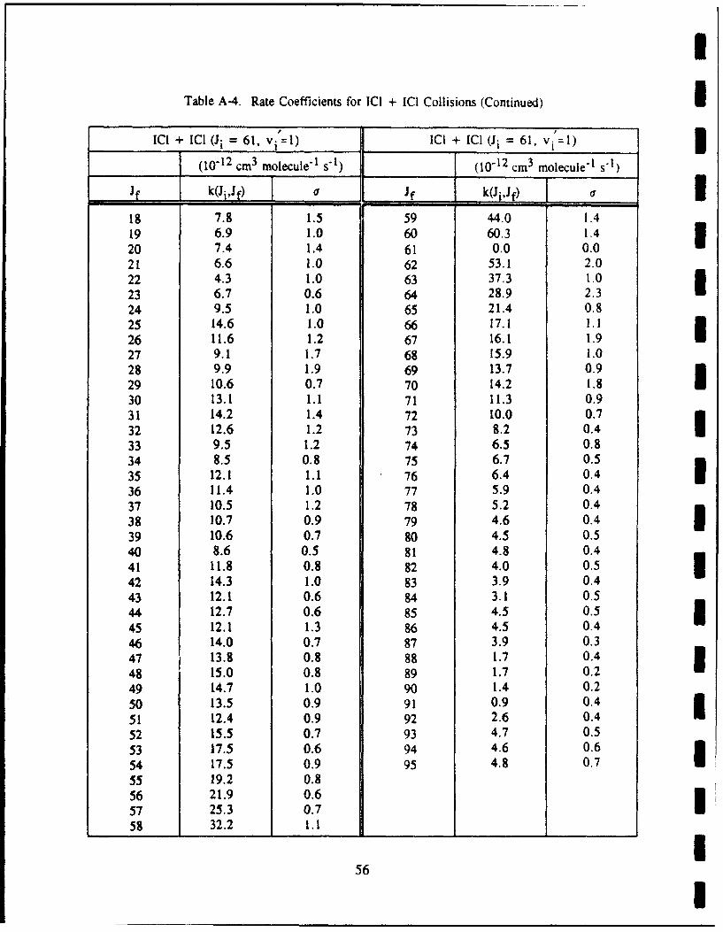
Table A-4. Rate Coefficients for ICI + ICI Collisions (Continued) n
ICI + ICI (Ji = 61, v, =1) ICI + ICI (Ji = 61, vi =1)
, (10-12 cm 3 molecule- 1 s-1) (10-12 cm 3 molecule-I s-1)
if k(Ji,Jf) a Jf k(J Jf) _ _ i18 7.8 1.5 59 44.0 1.419 6.9 1.0 60 60.3 1.420 7.4 1.4 61 0.0 0.021 6.6 1.0 62 53.1 2.022 4.3 1.0 63 37.3 1.023 6.7 0.6 64 28.9 2.324 9.5 1.0 65 21.4 0.825 14.6 1.0 66 17.1 1.126 11.6 1.2 67 16.1 1.927 9.1 1.7 68 15.9 1.028 9.9 1.9 69 13.7 0.929 10.6 0.7 70 14.2 1.830 13.1 1.1 71 11.3 0.931 14.2 1.4 72 10.0 0.732 12.6 1.2 73 8.2 0.4 I33 9.5 1.2 74 6.5 0.834 8.5 0.8 75 6.7 0.535 12.1 1.1 76 6.4 0.4 U36 11.4 1.0 77 5.9 0.437 10.5 1.2 78 5.2 0.438 10.7 0.9 79 4.6 0.4 I39 10.6 0.7 80 4.5 0.540 8.6 0.5 81 4.8 0.441 11.8 0.8 82 4.0 0.542 14.3 1.0 83 3.9 0.443 12.1 0.6 84 3.1 0.544 12.7 0.6 85 4.5 0.5
45 12.1 1.3 86 4.5 0.446 14.0 0.7 87 3.9 0.347 13.8 0.8 88 1.7 0.4 I48 15.0 0.8 89 1.7 0.2
49 14.7 1.0 90 1.4 0.250 13.5 0.9 91 0.9 0.451 12.4 0.9 92 2.6 0.4
52 15.5 0.7 93 4.7 0.553 17.5 0.6 94 4.6 0.6
54 17.5 0.9 95 4.8 0.755 19.2 0.856 21.9 0.657 25.3 0.758 32.2 1.1 11 1 1 1
56 I