engg. thermodynamics (etdy) module - 1: preliminaries and
TRANSCRIPT

ENGG. THERMODYNAMICS (ETDy)
Module - 1: Preliminaries and the Zeroth-Law of Thermodynamics
Lecture 1
Lecture 2
Lecture 3
Lecture 4
Lecture 5
Module - 2: First-Law of Thermodynamics and Analysis of Closed Systems
Lecture 6
Lecture 7
Lecture 8
Module-3: Thermodynamic Properties of Pure Substances
Lecture 9
Lecture 10
Lecture 11
Module - 4: First-Law of Thermodynamics for the Flow Processes
Lecture 12
Lecture 13
Lecture 14
Lecture 15
Module - 5: Second Law of Thermodynamics, Entropy and Availability.
Lecture 16
Lecture 17
Lecture 18
Lecture 19
Lecture 20
Lecture 21
Lecture 22

Lecture 23
Lecture 24
Lecture 25
Lecture 26
Module 6: Power and Refrigeration Cycles
Lecture 27
Lecture 28
Lecture 29
Lecture 30
Lecture 31
Module 7: Thermodynamic Relations
Lecture 32
Lecture 33
Module 8 : Gas Vapor Mixtures and Adiabatic Saturation
Lecture 34
Lecture 35
Lecture 36
Lecture 1 : Introduction
Introduction
The most of general sense of thermodynamics is the study of energy and its
relationship to the properties of matter. All activities in nature involve some
interaction between energy and matter. Thermodynamics is a science that
governs the following:
Energy and its transformation
Feasibility of a process involving transformation of energy
Feasibility of a process involving transfer of energy
Equilibrium processes
More specifically, thermodynamics deals with energy conversion, energy
exchange and the direction of exchange.
Areas of Application of Thermodynamics:
All natural processes are governed by the principles of thermodynamics. However, the
following engineering devices are typically designed based on the principles of
thermodynamics.
Automotive engines, Turbines, Compressors, Pumps, Fossil and Nuclear Power Plants,
Propulsion systems for the Aircrafts, Separation and Liquefication Plant, Refrigeration,
Air-conditioning and Heating Devices.
The principles of thermodynamics are summarized in the form of a set of axioms. These
axioms are known as four thermodynamic laws:
The zeroth law, the first law, the second law and the third law.

The Zeroth Law deals with thermal equilibrium and provides a means for
measuring temperatures.
The First Law deals with the conservation of energy and introduces the concept
of internal energy.
The Second Law of thermodynamics provides with the guidelines on the
conversion of internal energy of matter into work. It also introduces the concept
of entropy.
The Third Law of thermodynamics defines the absolute zero of entropy. The
entropy of a pure crystalline substance at absolute zero temperature is zero.
Different Approaches in the Study of Thermodynamics
Thermodynamics can be studied through two different approaches:
(a) Macroscopic Approach and
(b) Microscopic Approach

Macroscopic Approach
Consider a certain amount of gas in a cylindrical container. The volume (V) can be
measured by measuring the diameter and the height of the cylinder. The pressure (P) of
the gas can be measured by a pressure gauge. The temperature (T) of the gas can be
measured using a thermometer. The state of the gas can be specified by the measured P,
V and T . The values of these variables are space averaged characteristics of the
properties of the gas under consideration. In classical thermodynamics, we often use this
macroscopic approach. The macroscopic approach has the following features.
The structure of the matter is not considered.
A few variables are used to describe the state of the matter under consideration.
The values of these variables are measurable following the available techniques of
experimental physics.
Microscopic Approach
On the other hand, the gas can be considered as assemblage of a large number of particles
each of which moves randomly with independent velocity. The state of each particle can
be specified in terms of position coordinates ( xi , yi , zi ) and the momentum components
( pxi , pyi , pzi ). If we consider a gas occupying a volume of 1 cm3 at ambient temperature
and pressure, the number of particles present in it is of the order of 1020 . The same
number of position coordinates and momentum components are needed to specify the
state of the gas. The microscopic approach can be summarized as:
A knowledge of the molecular structure of matter under consideration is essential.
A large number of variables are needed for a complete specification of the state of
the matter.
SI Units
SI is the abbreviation of Système International d' Unités. The SI units for mass, length,
time and force are kilogram, meter, second and newton respectively. The unit of length is
meter, m, defined as
1 650 763.73 wavelengths in vacuum of the radiation corresponding to the orange-red
line of the spectrum of Krypton-86. The unit of time is second, s. The second is defined
as the duration of
9 192 631 770 cycles of the radiation associated with a specified transition of the Cesium
133 atom. The unit of mass is kilogram, kg. It is equal to the mass of a particular cylinder
of platinum-iridium alloy kept at the International Bureau of Weights and Measures. The
amount of substance can also be expressed in terms of the mole (mol). One kilomole of a

substance is the amount of that substance in kilograms numerically equal to its molecular
weight. The number of kilomoles of a substance, n , is obtained by dividing the mass (m)
in kilograms by the moleculare weight (M), in kg/ kmol.
The unit for temperature is Kelvin, K . One K is the fraction 1/273.16 of the
thermodynamic temperature of the triple point of water. Quite often the Celsius, oC , is
used to express the temperature of a substance.
The SI unit of force, called the newton, N is a secondary unit. The, N , is the force
required to accelerate a mass of 1 kilogram at the rate of 1 meter per (second)2 .
1 N = (1kg) (1m/s2 )= 1kg m/s2
The smaller or bigger quantities are expressed using the following prefixes
Factor Prefix Symbol Factor Prefix Symbol
1012 tera T 10-2 centi c
109 giga G 10-3 milli m
106 mega M 10-6 micro μ
103 kilo k 10-9 nano n
102 hecto h 10-12 pico p
Pressure
Pressure is the normal force exerted by a system against unit area of the boundary
surface.
where δA approaches zero.
The unit for pressure in SI is pacsal, Pa
1 Pa = 1 N/m2
Two other units are widely used
1 bar = 105 Pa = 100 kPa = 0.1 MPa
and the standard atmosphere, where
1 atm = 101.325 kPa = 1.01325 bar = pressure exerted by a columan of 760 mm of Hg
Energy
Energy is the capacity to exert a force through a distance. In SI, the unit of energy is
Newton-meter, N m or Joule, J.
Power
The rate of energy transfer or storage is called power. The unit of power is watt, W.
1 W = 1 J/s = 1 N m/s and 1 kW = 1000 W.
Apart from
these, the
following
units are
used for
various
parameters
of interest
Frequency, Hertz = Hz = s-1
Electric current, Ampere = A
Electric charge, Coulomb, C = As
Electric potential, Volt = V = W/A
Magnetic flux, Weber, Wb = Vs
Magnetic flux density, Tesla, T = Wb/m2

Lecture 2 : System, Surroundings and Properties
The lecture deals with
System
Surroundings
Types of Systems
Intensive and Extensive Properties
System
A thermodynamic system is defined as a definite quantity of matter or a region in space
upon which attention is focused in the analysis of a problem. We may want to study a
quantity of matter contained with in a closed rigid walled chambers, or we may want to
consider something such as gas pipeline through which the matter flows. The
composition of the matter inside the system may be fixed or may change through
chemical and nuclear reactions. A system may be arbitrarily defined. It becomes
important when exchange of energy between the system and the everything else outside
the system is considered. The judgement on the energetics of this exchange is very
important.
Surroundings
Everything external to the system is surroundings. The system is distinguished from its
surroundings by a specified boundary which may be at rest or in motion. The interactions
between a system and its surroundings, which take place across the boundary, play an
important role in thermodynamics. A system and its surroundings together comprise a
universe.
Types of systems
Two types of systems can be distinguished. These are referred to, respectively, as closed
systems and open systems or control volumes. A closed system or a control mass refers to
a fixed quantity of matter, whereas a control volume is a region in space through which

mass may flow. A special type of closed system that does not interact with its
surroundings is called an Isolated system .
Two types of exchange can occur between the system and its surroundings:
1. energy exchange (heat or work) and
2. exchange of matter (movement of molecules across the boundary of the system
and surroundings).
Based on the types of exchange, one can define
isolated systems: no exchange of matter and energy
closed systems: no exchange of matter but some exchange of energy
open systems: exchange of both matter and energy
If the boundary does not allow heat (energy) exchange to take place it is called adiabatic
boundary otherwise it is diathermal boundary.
Property
To describe a system and predict its behaviour requires a knowledge of its properties and
how those properties are related. Properties are macroscopic characteristics of a system
such as mass, volume, energy, pressure and temperature to which numerical values can
be assigned at a given time without knowledge of the past history of the system. Many
other properties are considered during the course of our study.
The value of a property of a system is independent of the process or the path
followed by the system in reaching a particular state.
The change in the value of the property depends only on the initial and the final
states.
The word state refers to the condition of a system as described by its properties.
Mathematically, if P is a property of the system, then the change in the property in going
from the initial state 1 to the final state 2 is given by
If P = P (x, y) then,

where,
If , then dP is said to be an exact differential, and P is a point function. A
thermodynamic property is a point function and not a path function. Pressure,
temperature, volume or molar volume are some of the quantities which satisfy these
requirements.
Intensive and Extensive Properties
There are certain properties which depend on the size or extent of the system, and there
are certain properties which are independent of the size or extent of the system. The
properties like volume, which depend on the size of the system are called extensive
properties. The properties, like temperature and pressure which are independent of the
mass of the system are called intensive properties. The test for an intensive property is
to observe how it is affected when a given system is combined with some fraction of
exact replica of itself to create a new system differing only by size. Intensive properties
are those which are unchanged by this process, whereas those properties whose values are
increased or decreased in proportion to the enlargement or reduction of the system are
called extensive properties.
Assume two identical systems S1 and S2 as shown in Figure 2.1 . Both the systems are in
identical states.
Let S3 be the combined system. Is the value of property for S3 same as that for S1 (and S2
)?

Figure 2.1
If the answer is yes, then the property is intensive
If the answer is no, then the property is extensive
The ratio of the extensive property to the mass is called the specific value of that property
specific volume, v = V/m = 1/ ρ ( ρ is the density)
specific internal energy, u = U/m
Similarly, the molar properties are defined as the ratios of the properties to the mole
number (N) of the substance
Molar volume = = V/N
Molar internal energy = = U/N

Lecture 3 : Energy and Processes
The lecture deals with
Energy
Macroscopic modes of Energy
Microscopic modes of Energy
Thermodynamic Equilibrium
Process
Energy
Energy is often defined as the capacity to produce work. However, this "capacity" has a
special significance. The capacity represents a combination of an effort and the change
brought about by the effort. However, the effort is exerted in overcoming resistance to a
particular type of change.
The effort involved is measured quantitatively as a "driving force" in thermodynamics. A
driving force is a property which causes and also controls the direction of change in
another property. The quantitative value of this change is called a "displacement". The
product of a driving force and its associated displacement represents a quantity of energy,
but in thermodynamics this quantity has meaning only in relation to a specifically defined
system.
Relative to a particular system there are generally two ways of locating a driving force
and the displacement it produces. In one way, the driving force and the displacement are
properties of the system and are located entirely within it. The energy calculated from
their product represents a change in the internal energy of the system. Similarly, both the
driving force and its displacement could be located entirely within the surroundings so
that the calculated energy is then a change in the total energy of the surroundings.
In another way, the displacement occurs within the system but the driving force is a
property of the surroundings and is applied externally at the system boundary. By
definition, the boundary of a system is a region of zero thickness containing no matter at
all so that the energy calculated in this way is not a property of matter either in the system
or in its surroundings but represents a quantity of energy in transition between the two. In
any quantitative application of thermodynamics it is always important to make a careful

distinction between energy changes within a system or within its surroundings and energy
in transition between them.
Macroscopic modes of energy
Kinetic Energy (KE)
If a body is accelerated from its initial velocity to final velocity , the total work
done on the body is
The work done on a body in accelerating it from its initial velocity to a final velocity
, is equal to the change in the kinetic energy of the body. If the body is decelerated
from a velocity to a velocity by the application of resisting force, the work done by
the body is equal to decrease in its kinetic energy.
Potential Energy (PE) A body of mass m is moved from an initial elevant Z1 to a final
elevation Z2(Fig 3.1)
Figure 3.1
The force on the body, F = mg
This force has moved a distance ( Z2 - Z1) . Therefore, the work
done on the body

�
The kinetic energy and potential energy are also called organized form of energy that can
be readily converted into work.
Microscopic modes of energy
The microscopic modes of energy refer to the energy stored in the molecular and atomic
structure of the system.
The molecules are in random motion. A molecule possesses energy in several forms.
Translational energy, Rotational energy, Vibrational energy.
Electronic energy, Chemical energy, Nuclear energy.
If ε represents energy of one molecule, then
If N is the total number of molecules in the system, then the total amount of microscopic
form of energy
U = N ε
We may also call this as INTERNAL ENERGY of the system. The internal energy, U is
due to random motions or disorganized motions of molecules. The internal energy cannot
be readily converted into work. One of the major tasks involved in thermodynamics is
devising means for converting disorganized internal energy into useful or organized
work.
Thermodynamic Equilibrium
Steady state
Under the steady state condition, the properties of the system at any location are
independent of time.

Equilibrium
At the state of equilibrium, the properties of the system are uniform and only one value
can be assigned to it.
In thermodynamics, equilibrium refers to a state of equilibrium with respect to all
possible changes, thermal, mechanical and chemical.
a. Thermal equilibrium
A state of thermal equilibrium can be described as one in which the temperature of the
system is uniform.
b. Mechanical equilibrium
Mechanical equilibrium means there is no unbalanced force. In other words, there is no
pressure gradient within the system.
c. Chemical equilibrium
The criterian for chemical equilibrium is the equality of chemical potential
Superscripts A and B refers to systems and subscript i refers to component
If Gibbs function is given by G, G = U + PV � TS
where ni is the number of moles of substance i . The composition of a system does not
undergo any change because of chemical reaction
Process
In thermodynamics we are mainly concerned with the systems which are in a state of
equilibrium. Whenever a system undergoes a change in its condition, from one
equilibrium state to another equilibrium state, the system is said to undergo a process.
Consider a certain amount of gas enclosed in a piston-cylinder assembly as our system.
Suppose the piston moves under such a condition that the opposing force is always
infinitesimally smaller than the force exerted by the gas. The process followed by the
system is reversible .
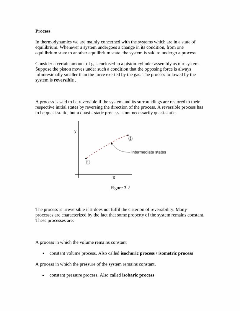
A process is said to be reversible if the system and its surroundings are restored to their
respective initial states by reversing the direction of the process. A reversible process has
to be quasi-static, but a quasi - static process is not necessarily quasi-static.
Figure 3.2
The process is irreversible if it does not fulfil the criterion of reversibility. Many
processes are characterized by the fact that some property of the system remains constant.
These processes are:
A process in which the volume remains constant
constant volume process. Also called isochoric process / isometric process
A process in which the pressure of the system remains constant.
constant pressure process. Also called isobaric process

A process in which the temperature of the system is constant.
constant temperature process. Also called isothermal process
A process in which the system is enclosed by adiabatic wall.
Adiabatic process
Lecture 4 : Work and Heat
The lecture deals with
Work
Thermodynamic Definition of Work
Heat
Work
Work is one of the basic modes of energy transfer. The work done by a system is a path
function, and not a point function. Therefore, work is not a property of the system,
and it cannot be said that the work is possessed by the system. It is an interaction
across the boundary. What is stored in the system is energy, but not work. A decrease in
energy of the system appears as work done. Therefore, work is energy in transit and it
can be indentified only when the system undergoes a process.
Work must be regarded only as a type of energy in transition across a well defined, zero
thickness, boundary of a system. Consequently work, is never a property or any quantity
contained within a system. Work is energy driven across by differences in the driving
forces on either side of it. Various kinds of work are identified by the kind of driving
force involved and the characteristic extensive property change which accompanied it.
Work is measured quantitatively in the following way. Any driving force other than
temperature, located outside the system on its external boundary, is multiplied by a
transported extensive property change within the system which was transferred across the
system boundary in response to this force. The result is the numerical value of the work

associated with this system and driving force. In static Equilibrium, F=PA (Fig 4.1). The
dX is small so that P does not change. The change in volume of the gas = AdX. The
elemental work,
dW=FdX=PAdX=PdV
Figure 4.1
Thermodynamic Definition of Work
In thermodynamics, work done by a system on its surroundings during a process is
defined as that interaction whose sole effect, external to the system, could be reduced as
the raising of a mass through a distance against gravitational force. Let us consider the
raising of mass m from an initial elevation z1 to final elevation z2 against gravitational
force. To raise this mass, the force acting on the mass is given by F = mg . The work
done on the body is W = mg( z2 - z1 )
An external agency is needed to act on the system
It can be seen that expansion of the gas gets reduced to raising a mass against
gravitational force (Figure 4.2)
dW = F dX = P A dX = P dV

Figure 4.2
During this expansion process, the external pressure is always infinitesimally smaller
than the gas pressure.
Figure 4.3
Compare two systems shown in the figure 4.3. Let the resistor be replaced by a motor
drawing the same amount of current as the resistor. The motor can wind a string and
thereby raise the mass which is suspended. As far as the battery is concerned, the
situations are identical. So, according to thermodynamic definition of work, the
interaction of a battery with a resistor is called work. By manipulating the environment,
that is external to the battery (system), the effect can be reduced to raising of a mass
against the gravitational force and that is the only effect on the surroundings. We can see
that the thermodynamic definition of work is more general than that used in mechanics.
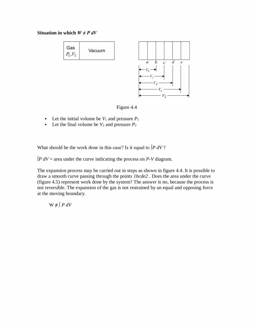
Situation in which W ≠ P dV
Figure 4.4
Let the initial volume be V1 and pressure P1
Let the final volume be V2 and pressure P2
What should be the work done in this case? Is it equal to ∫P dV ?
∫P dV = area under the curve indicating the process on P-V diagram.
The expansion process may be carried out in steps as shown in figure 4.4. It is possible to
draw a smooth curve passing through the points 1bcde2 . Does the area under the curve
(figure 4.5) represent work done by the system? The answer is no, because the process is
not reversible. The expansion of the gas is not restrained by an equal and opposing force
at the moving boundary.
W ≠ ∫ P dV

Figure 4.5
No external force has moved through any distance in this case, the work done is zero.
Therefore, we observe that
W = ∫ P dV only for reversible process
W ≠ ∫ P dV for an irreversible process
Another exceptional situation !
The piston is held rigid using latches ! (Figure 4.6)
dV = 0
Work done on the gas is equal to the decrease in the potential energy of mass m
A situation where dV = 0 and yet dW is not zero
such work can be done in one direction only. Work is done on the system by the
surroundings
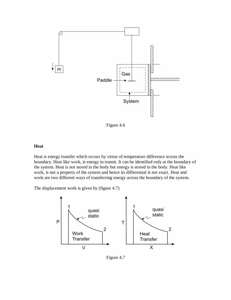
Figure 4.6
Heat
Heat is energy transfer which occurs by virtue of temperature difference across the
boundary. Heat like work, is energy in transit. It can be identified only at the boundary of
the system. Heat is not stored in the body but energy is stored in the body. Heat like
work, is not a property of the system and hence its differential is not exact. Heat and
work are two different ways of transferring energy across the boundary of the system.
The displacement work is given by (figure 4.7)
Figure 4.7

It is valid for a quasi-static or reversible process. The work transfer is equal to the
integral of the product of the intensive property P and the differential change in the
extensive property, dV .
Just like displacement work, the heat transfer can also be written as
The quantity dQ is an inexact differential.
dQ = TdX
X is an extensive property and dX is an exact differential. The extensive property is yet to
be defined. We shall see later that X is nothing but the entropy, S of a system.
It is possible to write
or,
where is integrating factor.

Lecture 5 : State Postulate and Zeroth- Law of Thermodynamics
The lecture deals with
Introduction to state postulate
Zeroth Law of Thermodynamics
Temperature Scale
Perfect Gas Scale
Introduction to state postulate
Since every thermodynamic system contains some matter with energy in its various
forms, the system can be completely described by specifying the following variables.
The composition of the matter in terms of mole numbers of each constituent.
The energy of the system.
The volume of the system, and
The measurable properties, such as pressure and temperature.
By specifying these quantities, the state of the system is defined. Once the system is in a
given state, it possesses a unique state of properties like pressure, P , temperature, T ,
density, etc. All the properties of a system cannot be varied independently since they are
interrelated through expressions of the following type
For example, the pressure, temperature and molar volume ( ) of an ideal gas are related
by the expression P = RT . Here R is a constant. Only two of the three variables P , and
T can be varied independently. Question is that for a given thermodynamics system, how
many variables can be varied independently.
The State Postulate
As noted earlier, the state of a system is described by its properties. But we know from
experience that we do not need to specify all the properties in order to fix a state. Once a

sufficient number of properties are specified, the rest of the properties assume certain
values automatically. The number of properties required to fix the state of a system is
given by the state postulate:
The state of a simple compressible system is completely specified by two
independent properties.
A system is called a simple compressible system in the absence of electrical, magnetic,
gravitational, motion, and surface tension effects. These effects are due to external force
fields and are negligible for most engineering problems. Otherwise, an additional
property needs to be specified for each effect which is significant. If the gravitational
effects are to be considered, for example, the elevation z needs to be specified in addition
to the two properties necessary to fix the state.
The state postulate is also known as the two-property rule.
The state postulate requires that the two properties specified be independent to fix the
state. Two properties are independent if one property can be varied while the other one is
held constant. Temperature and specific volume, for example, are always independent
properties, and together they can fix the state of a simple compressible system (Fig. 5.1).
Figure 5.1
For a simple compressible substance (gas), we need the following properties to fix the
state of a system:
ρ or PT or T or uP or u . Why not u and T? They are closely related. For ideal gas
u=u(t)
Temperature and pressure are dependent properties for multi-phase systems. At sea level
( P = 1 atm), water boils at 100oC, but on a mountain-top where the pressure is lower,
water boils at a lower temperature. That is, T = f (P) during a phase-change process, thus
temperature and pressure are not sufficient to fix the state of a two-phase system.

Therefore, by specifying any two properties we can specify all other state properties. Let
us choose P and
Then
T = T(P, )
u = u(P, ) etc.
Can we say W = W(p, )
No. Work is not a state property, nor is the heat added (Q) to the system.
Zeroth Law of Thermodynamics
Statement: If a body 1 is in thermal equilibrium with body 2 and body 3, then the body 2
and body 3 are also in thermal equilibrium with each other
Figure 5.2
Two systems 1 and 2 with independent variables ( U1 , V1 , N1 ) and (U2 , V2 , N2 ) are
brought into contact with each other through a diathermal wall (figure 5.2). Let the
system 1 be hot and system 2 be cold. Because of interaction, the energies of both the
systems, as well as their independent properties undergo a change. The hot body becomes
cold and the cold body becomes hot. After sometime, the states of the two systems do not
undergo any further change and they assume fixed values of all thermodynamic
properties. These two systems are then said to be in a state of thermal equilibrium with
each other. The two bodies which are in thermal equilibrium with each other have a
common characteristic called temperature. Therefore temperature is a property which has
the same value for all the bodies in thermal equilibrium.

Suppose we have three systems 1, 2 and 3 placed in an adiabatic enclosure as shown in
figure 5.3.
Figure 5.3
The systems 1 and 2 do not interact with each other but they interact separately with
systems 3 through a diathermal wall. Then system 1 is in thermal equilibrium with
system 3 and system 2 is also in thermal equilibrium with system 3. By intuition we can
say that though system 1 and 2 are not interacting, they are in thermal equilibrium with
each other.
Suppose system 1 and 2 are brought into contact with each other by replacing the
adiabatic wall by a diathermal wall as shown in figure 5.3 (B). Further they are isolated
from system 3 by an adiabatic wall. Then one observes no change in the state of the
systems 1 and 2.
Temperature Scale
Based on zeroth law of thermodynamics, the temperature of a group of bodies can be
compared by bringing a particular body (a thermometer) into contact with each of them in
turn. To quantify the measurement, the instrument should have thermometric properties.
These properties include: The length of a mercury column in a capillary tube, the
resistance (electrical) of a wire, the pressure of a gas in a closed vessel, the emf generated
at the junction of two dissimilar metal wires etc. are commonly used thermometric
properties.
To assign numerical values to the thermal state of a system, it is necessary to establish a
temperature scale on which temperature of a system can be read. Therefore, the

temperature scale is read by assigning numerical values to certain easily reproducible
states. For this purpose, it is customary to use
a. Ice Point: The equilibrium temperature of ice with air saturated water at
standard atmospheric pressure which is assigned a value of 0oC.
b. Steam Point: The equilibrium temperature of pure water with its own
vapor at standard atmospheric pressure, which is assigned a value of
100oC.
This scale is called the Celsius Scale named after Anders Celsius.
Perfect Gas Scale
An ideal gas obeys the relation
P = R T
where R is the Universal Gas Constant ( R = 8.314 J/mol K). This equation is only an
approximation to the actual behavior of the gases. The behavior of all gases approaches
the ideal gas limit at sufficiently low pressure (in the limit P 0). The perfect gas
temperature scale is based on the observation that the temperature of a gas at
constant volume increases monotonically with pressure. If the gas pressure is made to
approach zero, the gas behavior follows the relation
P = R T
Figure 5.4 shows a constant volume gas thermometer.
The bulb is placed in the system whose temperature is to be measured. The mercury
column is so adjusted that the level of mercury stands at the reference mark S . This
ensures that the volume of the gas is held at a constant value. Let the pressure of the gas
be read as P. Let a similar measurement be made when the gas bulb is maintained at the
triple point of water, Ptp. We can obtain triple point by putting water and ice in an
insulated chamber and evacuating air ( which is then replaced by water vapour).

Figure 5.4
The temperature of the triple point of water has been assigned a value of 273.16 K. Since
for an ideal gas T varies as P ,
or,
where Ttp is the triple point temperature of water.
Suppose a series of measurements with different amounts of gas in the bulb are made.
The measured pressures at the triple point as well as at the system temperature change
depending on the amount of gas in the bulb. A plot of the temperature Tcal , calculated
from the expression T = 273.16 ( P/ P tp ) as a function of the pressure at the triple point,
results in a curve as shown in figure 5.5.
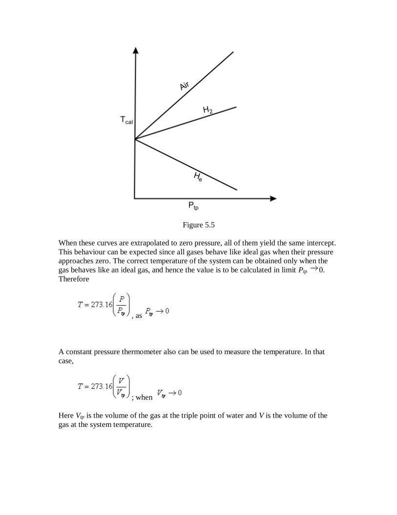
Figure 5.5
When these curves are extrapolated to zero pressure, all of them yield the same intercept.
This behaviour can be expected since all gases behave like ideal gas when their pressure
approaches zero. The correct temperature of the system can be obtained only when the
gas behaves like an ideal gas, and hence the value is to be calculated in limit Ptp 0.
Therefore
, as
A constant pressure thermometer also can be used to measure the temperature. In that
case,
; when
Here Vtp is the volume of the gas at the triple point of water and V is the volume of the
gas at the system temperature.

Lecture 6 :
The lecture deals with
First Law of Thermodynamics
Heat is a Path Function
Energy is a Property of the System
A Perpetual Motion Machine of First Kind
Analysis of Closed Systems
First Law of Thermodynamics
A series of Experiments carried out by Joule between 1843 and 1848 from the basis for
the First Law of Thermodyanmics
The following are the observations during the Paddle Wheel experiment shown in Fig.
6.1.
Figure 6.1
Work done on the system by lowering the mass m through = change in
PE of m

Temperature of the system was found to increase
System was brought into contact with a water bath
System was allowed to come back to initial state
Energy is transferred as heat from the system to the bath
The system thus executes a cycle which consists of work input to the system followed by
the transfer of heat from the system.
(6.1)
Whenever a system undergoes a cyclic change, however complex the cycle may be, the
algebraic sum of the work transfer is equal to the algebraic sum of the energy transfer as
heat (FIRST LAW OF THERMODYNAMICS).
Sign convention followed in this text:
Work done by a system on its surroundings is treated as a positive quantity.
Energy transfer as heat to a system from its surroundings is treated as a
positive quantity
(6.2)
or,
Heat is Path Function
Lets us consider following two cycles: 1a2b1 and la2cl and apply the first law of
thermodynamics Eq (6.2) to get

Figure 6.2
(6.3)
or,
(6.4)
Subtracting Eq. (6.4) from Eq. (6.3)
(6.5)
Since, work depends on the path
(6.6)
Therefore,
(6.7)
Energy transfer as heat is not a point function, neither is it a property of the system.

Heat interaction is a path function.
Energy is a Property of the System
Refer to Figure 6.2 again and consider Eq. (6.5)
(6.8)
and depend on path function followed by the system. The quantity
is the same for both the processes and connecting the states 2 and 1.
The quantity does not depend on path followed by the system, depends on
the initial and final states. Hence is an exact differential.
Differential of property of the system
This property is the internal energy of system, E
(6.9)
Energy of an Isolated System
An isolated system is one in which there is no interaction of the system with the
surroundings. For an isolated system
(6.10)
A Perpetual Motion Machine of First Kind
Thermodynamics originated as a result of man's endeavour to convert the disorganized
form of energy (internal energy) into organized form of energy (work).

(6.11)
An imaginary device which would produce work continuously without absorbing any
energy from its surroundings is called a Perpetual Motion Machine of the First kind,
(PMMFK). A PMMFK is a device which violates the first law of thermodynamics. It is
impossible to devise a PMMFK (Figure 6.3)
Figure 6.3
The converse of the above statement is also true, i.e., there can be no machine which
would continuously consume work without some other form of energy appearing
simultaneously.
Analysis of Closed System
Let us consider a system that refers to a definite quantity of matter which remains
constant while the system undergoes a change of state. We shall discuss the following
elementary processes involving the closed systems.
Constant Volume Process
Our system is a gas confined in a rigid container of volume V (Refer to Figure 6.4)

Figure 6.4
Let the system be brought into contact with a heat source.
The energy is exchanged reversibly. The expansion work done (PdV) by the
system is zero.
Applying the first law of thermodynamics, we get
(6.12)
or,
(6.13)
Hence the heat interaction is equal to the change in the internal energy of the
system.
Constant Volume Adiabatic Process
Refer to Figure 6.5 where a change in the state of the system is brought about by
performing paddle wheel work on the system.

Figure 6.5
The process is irreversible. However, the first law gives
(6.14)
or
(6.14)
Interaction of heat and irreversible work with the system is same in nature. (-W)
represents the work done on the system by the surroundings
Specific Heat at Constant Volume
By definition it is the amount of energy required to change the temperature of a unit mass
of the substance by one degree.

(6.16)
While the volume is held constant. For a constant volume process, first law of
thermodynamics gives
(6.17)
Therefore,
(6.18)
Where is the specific internal energy of the system. If varies with temperature, one
can use mean specific heat at constant volume
(6.19)
The total quantity of energy transferred during a constant volume process when the
system temperature changes from
(6.20)
The unit for is kJ/kgK. The unit of molar specific heat is kJ/kmolK.
Lecture 7 :
The lecture deals with
Constant Pressure Process 1
Constant Pressure Process 2
Specific Heat at Constant Pressure
Constant Temperature Process
Adiabatic Process
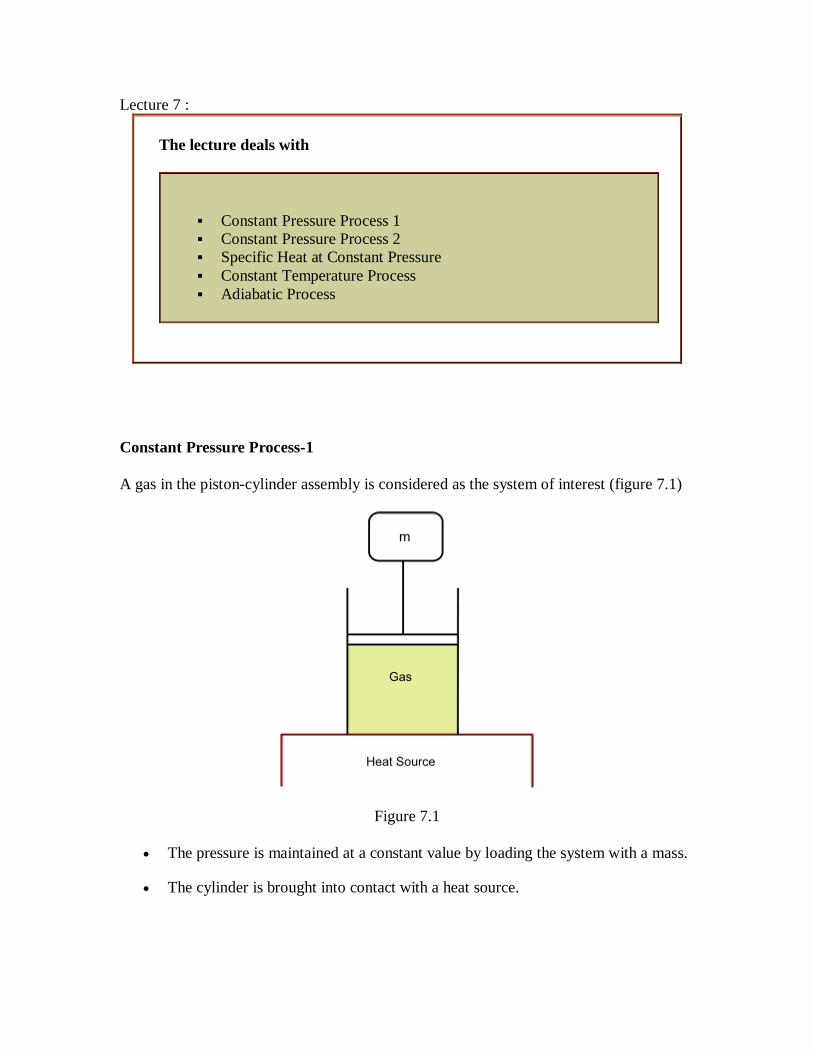
Constant Pressure Process-1
A gas in the piston-cylinder assembly is considered as the system of interest (figure 7.1)
Figure 7.1
The pressure is maintained at a constant value by loading the system with a mass.
The cylinder is brought into contact with a heat source.

Energy transfer as heat takes place reversibly. The work is done by system when it
changes from the initial state (1) to the final state (2).
(7.1)
Applying the first law, we get
(7.2)
or
(7.3)
or
(7.4)
The quantity is known as enthalpy, H (a property) of the system. The specific
enthalpy h is defined as
(7.5)
The molar enthalpy is , where N is the mole number of the substance.
Constant Pressure Process-2
Let us assume paddle wheel work is done on the system figure 7.2. Also, consider
adiabatic walls, so that

Figure 7.2
Now the application of first law enables us to write
(7.6)
or
(7.7)
or
(7.8)
Therefore, the increase in the enthalpy of the system is equal to the amount of shaft work
done on the system.

Specific Heat at Constant Pressure
Let us focus on Figure 7.3
Figure 7.3
System changes its state from 1 to 2 following a constant pressure process.
There will be an accompanying change in temperature.
Specific heat at constant pressure is defined as the quantity of energy required to change
the temperature of a unit mass of the substance by one degree during a constant pressure
process.
(7.9)
The total heat interaction for a change in temperature from T1to T2 can be calculated from
(7.10)
The molar specific heat at constant pressure can be defined as
(7.11)

Constant Temperature process
Let us refer to figure 7.4
Figure 7.4
The system is allowed to undergo an expansion process while in contact with constant
temperature bath. During the expansion process, the opposing force is continuously
reduced. System is in equilibrium at all times. Applying the first law, one can write
(7.12)
For an ideal gas, the desired property relations are
and (7.13)
Since the temperature is held constant, du=0 and Q=W . We can also write
Adiabatic Process
1. Irreversible Adiabatic Process
A process in which there is no energy transfer as heat across the boundaries of the
system, is called an adiabatic process. For an adiabatic process, Q=0. Paddle wheel work
is performed on the system (Figure 7.5).

Figure 7.5
Application of first law gives
(7.15)
or
(7.16)
2. Reversible Adiabatic (ISENTROPIC) Process
Consider a gas contained in the cylinder piston assembly as the system. The cylinder wall
and the piston act as adiabatic walls. Suppose the gas is allowed to expand from the
initial pressure P1 to the final pressure P2 and the opposing pressure is so adjusted that it
is equal to inside gas pressure. For such a process, dW=PdV
The first-law of thermodynamics will give
Let us consider the system as an ideal gas which satisfies the relation and
. Also, we know that .
or
(7.17)
or,

(7.18)
or
(7.19)
or
For an ideal gas,
Therefore,
(7.20)
The ratio of specific heats is given by
(7.21)
or,
(7.22)
Thus,
(7.23)
Therefore when an ideal gas expands reversibly and adiabatically from the initial state
to final state , the work done per mole of the gas is given by the
above expression.

Lecture 8 :
The lecture contains
Characterisation of Reversible Adiabatic Process
Polytropic Process
Ideal Gas Model
Characterisation of Reversible Adiabatic Process
Let us find out the path followed by the system in reaching the final sate starting from the
initial state. We have already seen that for an ideal gas
(8.1)
or,
(8.2)
or,
(8.3)
or,
(8.4)
or
= constant
(8.5)
Since,
(8.6)
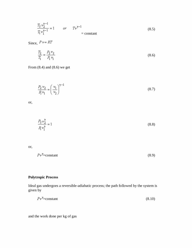
From (8.4) and (8.6) we get
(8.7)
or,
(8.8)
or,
=constant (8.9)
Polytropic Process
Ideal gas undergoes a reversible-adiabatic process; the path followed by the system is
given by
=constant (8.10)
and the work done per kg of gas
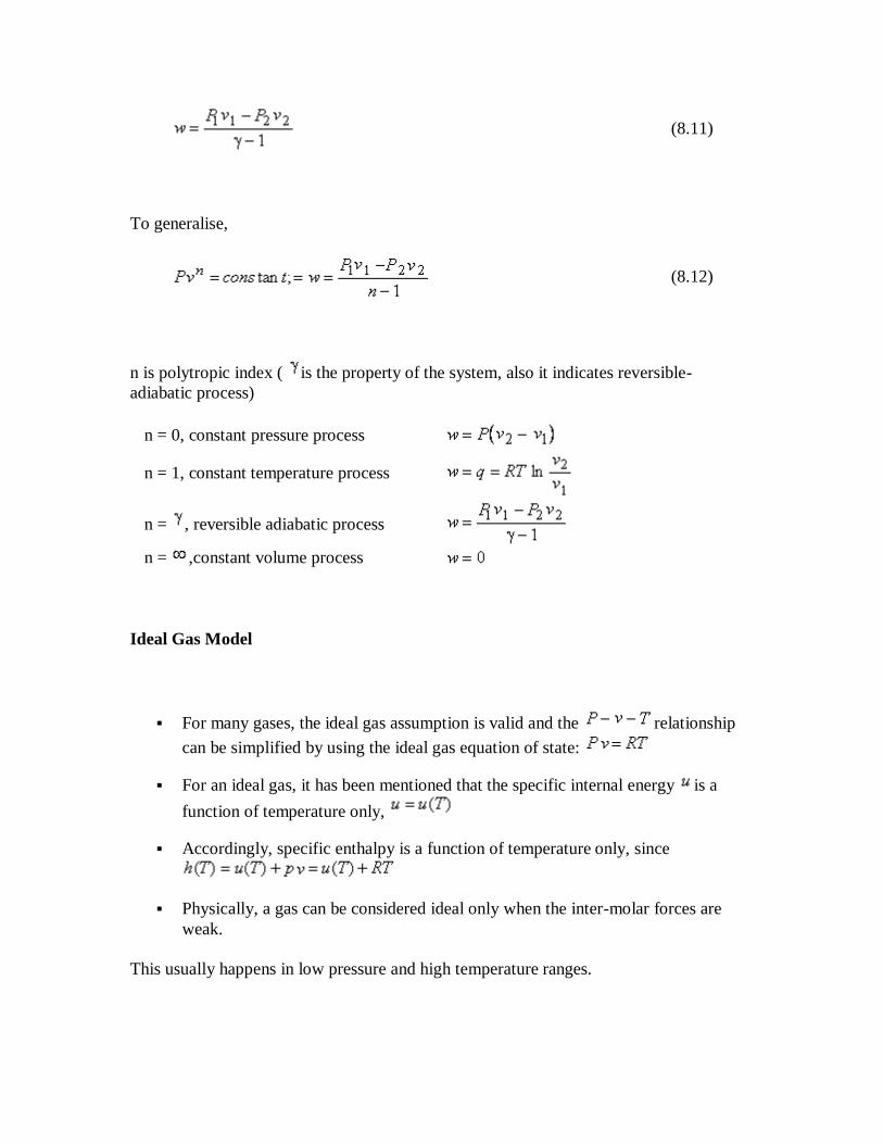
(8.11)
To generalise,
(8.12)
n is polytropic index ( is the property of the system, also it indicates reversible-
adiabatic process)
n = 0, constant pressure process
n = 1, constant temperature process
n = , reversible adiabatic process
n = ,constant volume process
Ideal Gas Model
For many gases, the ideal gas assumption is valid and the relationship
can be simplified by using the ideal gas equation of state:
For an ideal gas, it has been mentioned that the specific internal energy is a
function of temperature only,
Accordingly, specific enthalpy is a function of temperature only, since
Physically, a gas can be considered ideal only when the inter-molar forces are
weak.
This usually happens in low pressure and high temperature ranges.

(8.13)
(8.14)
• Specific heat ratio
(8.15)
(8.16)
or,
(8.17)
or,
(8.18)
In some cases, the temperature dependence of the specific heat can be written in
polynomial form.
Otherwise, ideal gas tables are also available. They are easier to use compared to
the thermodynamic tables since temperature is the only parameter.

Lecture 9 : Thermodynamic Properties of Fluids
The lecture deals with
Thermodynamic Properties of Fluids
Pure substance
Equations of State
Ideal Gas
Thermodynamic Properties of fluids
Most useful properties:
Properties like pressure, volume and temperature which can be measured directly.
Also viscosity, thermal conductivity, density etc can be measured.
Properties like internal energy, enthalpy etc. which cannot be measured directly
Pure Substance
A pure substance is one which consists of a single chemical species.
Concept of Phase
Substances can be found in different states of aggregation. Ice, water and steam are the
three different physical states of the same species . Based on the physical states of
aggregation the substances are generally classified into three states as
a. Solid
b. liquid

c. gas
The different states of aggregation in which a pure substance can exist, are called its
phases. Mixtures also exist in different phases. For example, a mixture of alcohal and
water can exist in both liquid and vapour phases. The chemical composition of the vapour
phase is generally different from that of the liquid phase.
Generalizing the above observations, it can be said that a system which is uniform
throughout both in chemical composition and physical state, is called a homogeneous
substance or a phase.
All substances,-solids, liquids and gases, change their specific volume depending on the
range of applied pressure and temperature.
When the changes in the specific volume is negligible as in the case of liquids and solids,
the substance may be treated as incompressible.
The isothermal compressibility of a substance κ is defined as
The coefficient of volume expansion of a substance is defined as

Equations of State
Equations that relate the pressure, temperature and specific volume or molar volume of a
substance. They predict the relationship of a �gas� reasonably well within
selected regions.
Boyle's law:
at constant pressure
or,
Constant at constant temperature
Charles' Law:
At constant pressure
At constant volume
Boyle's law and Charles' law can be combined to yield

Where R is the characteristic gas constant. If the specific volume is substituted by the
molar volume, then R is substituted by the universal gas constant, 8.314 kJ / kmol
K. Again, it can be shown that for an ideal gas .
In summary, the Ideal gas equation:
where R is the specific constant
, where is the universal gas constant (8.314 kJ / k mole K) M is the molar
mass, defined as the mass of one mole of a substance. We can also write where
is the molar volume.
Example: M = 28 kg / kmol for nitrogen (since its molar mass is 28)
M =32 kg / kmol for oxygen ( O2 with a molar mass of 32)
Note: Many gases such as air, oxygen can be treated as ideal gases. However, dense
gases such as water vapor and refrigerant vapor should not be treated as ideal gas. Use
property table instead.
deal Gas
The kinetic theory of gases model a gas as a collection of elastic particles. The statistical
analysis of these with some assumptions results as the ideal gas law
Most gases deviate from ideal gas in the vicinity of the critical point and saturated
vapour line
.
Most gases behaves like ideal gas at high temperature and low pressure regions.
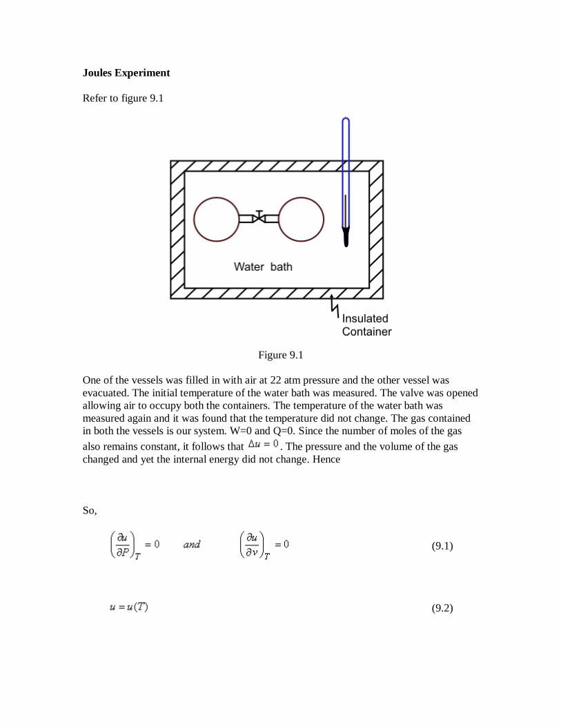
Joules Experiment
Refer to figure 9.1
Figure 9.1
One of the vessels was filled in with air at 22 atm pressure and the other vessel was
evacuated. The initial temperature of the water bath was measured. The valve was opened
allowing air to occupy both the containers. The temperature of the water bath was
measured again and it was found that the temperature did not change. The gas contained
in both the vessels is our system. W=0 and Q=0. Since the number of moles of the gas
also remains constant, it follows that . The pressure and the volume of the gas
changed and yet the internal energy did not change. Hence
So,
(9.1)
(9.2)

Since,
(9.3)
(9.4)
Van der Waal's equation of state:
The gases at low pressure and high temperatures follow ideal gas law. Gases that do not
follow ideal gas law are required to be represented by a similar set of mathematical
relations. The first effort was from clausius.
Clausius Proposed
(9.5)
Van der Waals, by applying the laws of mechanics to individual molecules, introduced
two correction terms in the equation of ideal gas. Van der Waals equation of state is
given by.
(9.6)
The term accounts for the intermolecular forces and b accounts for the volume
occupied by the gas molecules.
Since Van der Waal's equation takes into account the inter-molecular forces, it is
expected to hold good for liquid phase also. Now a days, the Van der Waal's equation is
used to predict the phase equilibrium data. The constants and b are determined from
experimental data. However, rearranging the Van der Waal's equation, we get
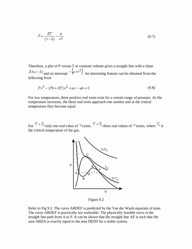
(9.7)
Therefore, a plot of P versus T at constant volume gives a straight line with a slope
and an intercept . An interesting feature can be obtained from the
following form
(9.8)
For low temperature, three positive real roots exist for a certain range of pressure. As the
temperature increases, the three real roots approach one another and at the critical
temperature they become equal.
For only one real value of exists. three real values of exists, where is
the critical temperature of the gas.
Figure 9.2
Refer to Fig 9.2. The curve ABDEF is predicted by the Van der Waals equation of state.
The curve ABDEF is practically not realizable. The physically feasible curve is the
straight line path from A to F. It can be shown that the straight line AF is such that the
area ABDA is exactly equal to the area DEFD for a stable system.

Lecture 10 : The Constants of Van der Waals Equation and Compressibility Chart
The lecture deals with
The Van der Waals Constants
Virial Equation od State
Compressibility Chart
The Van der Waals Constants
The constants and are different for different substances. We can get the estimates
of and of a substance by knowing the critical values of that substance.
Before we proceed further, let us look at the mathematical function
For the maximum value of x: and
For the minimum value of x: and
For the point of inflection, and
From the Figure 9.2 we can see that the critical point is a point of inflection.
The critical isotherm must show a point of inflection at the critical point
(10.1)
(10.2)
At the critical point, the Van der Waals equation is

(10.3)
One can solve the above three equations to obtain
(10.4)
Alternatively, one can calculate the Van der Waals constants and in terms of
critical constants.
(10.5)
The constants and can be determined for any substance from the critical point
data (Table 10-1) At the critical point, one can see that
(10.6)
Table 10.1 Some typical values of Van der Waals constants
Gas Constants
kPa (m3/ kmol)2 Constants
( m3/ kmol )
Air 135.8 0.0364
Ammonia (NH3 ) 423.3 0.0373
Carbon-dioxide(CO2 ) 364.3 0.0427
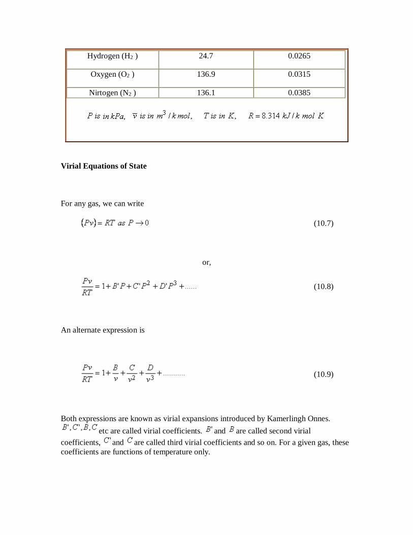
Hydrogen (H2 ) 24.7 0.0265
Oxygen (O2 ) 136.9 0.0315
Nirtogen (N2 ) 136.1 0.0385
Virial Equations of State
For any gas, we can write
(10.7)
or,
(10.8)
An alternate expression is
(10.9)
Both expressions are known as virial expansions introduced by Kamerlingh Onnes.
etc are called virial coefficients. and are called second virial
coefficients, and are called third virial coefficients and so on. For a given gas, these
coefficients are functions of temperature only.

Compressibility Chart
To quantify deviation of real behavior from the ideal gas behavior, we introduce a new
term namely, the compressibility factor. The compressibility factor Z is defined as the
ratio of the actual volume to the volume predicted by the ideal gas law at a given
temperature and pressure.
Z = (Actual volume) / (volume predicted by the ideal gas law)
(10.10)
If the gas behaves like an ideal gas, Z =1 at all temperatures and pressures. A plot of Z as
a function of temperature and pressure should reveal the extent of deviation from the
ideal gas law. Figure 10.1 shows a plot of Z as a function of temperature and pressure for
N2.
Figure 10.1
For each substance, a compressibility factor chart or compressibility chart is available.

Figure 10.2
It would be very convenient if one chart could be used for all substances. The general
shapes of the vapour dome and of the constant temperature lines on the plane are
similar.
This similarity can be exploited by using dimensionless properties called reduced
properties. The reduced pressure is the ratio of the existing pressure to the critical
pressure of the substance and the same is followed for the reduced temperature and
reduced volume. Then
(10.11)
At the same temperature and pressure, the molar volumes of different gases are different.
However, it is found from experimental data that at the same reduced pressure and
reduced temperature, the reduced volumes of different gases are approximately the same.
Therefore for all substances
(10.12)
or,
(10.13)

Where is called critical compressibility factor. Experimental
values of for most substance fall with in a narrow range 0.2-0.3. Therefore from the
above equation we can write
(10.14)
When Z is plotted as a function of reduced pressure and , a single plot, known as
general compressibility chart (Figure 10.2) is found to be satisfactory for a wide variety
of substances. Although necessarily approximate, the plots are extremely useful in
situations where detailed data on a particular gas are lacking but its critical properties are
available.
Lecture 11 : Phase-Change Process of Pure Substances
The lecture deals with
Graphical Representation of Data for Pure Substances
Specific internal energy and enthalpy
Steam Tables
There are certain situations when two phases of a pure substance coexist in equilibrium.
As a commonly used substance water may be taken up to demonstrate the basic principles
involved. However, all pure substances exhibit the same general behaviour.
We shall remember the following definitions:
Saturated State: A state at which a phase change begins or ends
Saturation Temperature: Temperature at which phase change (liquid-vapour) begins or
ends at a given pressure

Saturation Pressure: It is the pressure at which phase change begins or ends at a
specified temperature.
Saturated Liquid: It is the substance at which is fully liquid (no-vapour).
Saturated Vapour: It is the substance at which is fully vapour (no-liquid).
Subcooled liquid: If the temperature of the liquid (T) is less then then the liquid is
called sub-cooled liquid.
Superheated vapour: If the temperature of the vapour (T) is greater than then the
vapour is called superheated vapour.
Graphical Representation of Data for Pure Substances
The commonly used thermodynamic diagrams are
a. Pressure versus Temperature ( P − T )
b. Pressure versus Volume ( P − )
c. Temperature versus Volume (T − )

d. Temperature versus entropy ( T − S )
e. Enthalpy versus entropy ( h − S )
f. Pressure versus enthalpy ( P − h )
(a) Pressure-Temperature Diagram
For water , at 100 kPa, the saturation temperature is 99.60C. Alternatively at 99.60C, the
saturation pressure is 100 kPa. Quite often, the saturation pressure is called the vapour
pressure.
Figure 11.1
Refer to figure 11.1, The segment 1-T represents sublimation process during which solid
and vapour phases coexist in equilibrium. The segment 2-T represents fusion process
during which solid and liquid phases coexist in equilibrium. The segment T-C represents
vapourization .
Sublimation curve 1-T separates solid and vapour. 2-T separates solid and liquid and T-
C separates liquid and vapour. Three curves meet at T, which is called the triple-point,
where all the three phases-solid, liquid and vapour coexist in equilibrium. At the triple
point no thermodynamic property of the system can be varied independenty. The system
is said to be invariant.

Along, 1-T, or T-C, the system is univariant , that is only one thermodynamic property of
the system can be varied independently. The system is bivariant in the single phases
region.
The curve 2-T can be extended indefinitely, the curve T-C terminates at point C which is
called the critical point .
The critical point represents highest temperature and pressure at which both the liquid
phase and vapour phase can coexist in equilibrium.
At the critical point , the specific volumes and all other thermodynamic properties of
the liquid phase and the vapour phase are indentical.
and are called the critical temperature and critical pressure, respectively. If the
substance exist as a liquid on the curve T−C, it is called saturated liquid, and if it exists
as a vapour, it is called a saturated vapour. Under the constant pressure, the line abc
indicates melting, - sublimation and - vaporization.
(b) Diagram
Refer to the diagram as shown in Figure 11.2.

Figure 11.2
The isotherm is at a temperature greater than the critical temperature . The
isotherms and are at temperatures less than the critical temperature and they cross
the phase boundary. The point C represents the critical point. The curve AC is called the
saturated liquid line; and the curve CB is called the saturated vapour line. The area under
the curve ACB is the two-phase region where both liquid and vapour phase are present.
Left to the curve AC is the liquid region. Region to the right of curve CB is the vapour
region
The isotherm appears in three segments: DE, EF and FG. DE is almost vertical,
because the change in the volume of liquid is very small for a large change in pressure.
The segment FG is less steep because vapour is compressible. Segment EF is horizontal,
because the phase change from liquid to vapour occurs at constant pressure and constant
temperature for a pure substance. EF represents all possible mixtures of saturated liquid
and saturated vapour. The total volume of the mixture is the sum of the volumes of the
liquid and vapour phases.
(11.1)
Dividing by the total mass m of the mixture, m an average specific volume for mixture is
obtained
(11.2)
Since the liquid phase is a saturated liquid and the vapour phase is a saturated vapour,
(11.3)
so,
(11.4)
Introducing the definition of quality or dryness fraction and noting that
the above expression becomes
(11.5)
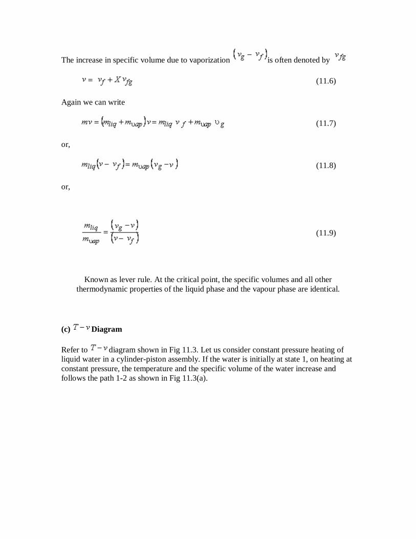
The increase in specific volume due to vaporization is often denoted by
(11.6)
Again we can write
(11.7)
or,
(11.8)
or,
(11.9)
Known as lever rule. At the critical point, the specific volumes and all other
thermodynamic properties of the liquid phase and the vapour phase are identical.
(c) Diagram
Refer to diagram shown in Fig 11.3. Let us consider constant pressure heating of
liquid water in a cylinder-piston assembly. If the water is initially at state 1, on heating at
constant pressure, the temperature and the specific volume of the water increase and
follows the path 1-2 as shown in Fig 11.3(a).
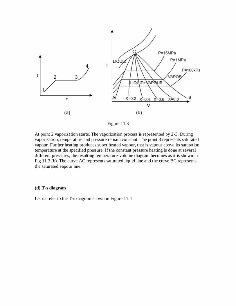
Figure 11.3
At point 2 vaporization starts. The vaporization process is represented by 2-3. During
vaporization, temperature and pressure remain constant. The point 3 represents saturated
vapour. Further heating produces super heated vapour, that is vapour above its saturation
temperature at the specified pressure. If the constant pressure heating is done at several
different pressures, the resulting temperature-volume diagram becomes as it is shown in
Fig 11.3 (b). The curve AC represents saturated liquid line and the curve BC represents
the saturated vapour line.
(d) T-s diagram
Let us refer to the T-s diagram shown in Figure 11.4

Figure 11.4
(e) Enthalopy-entropy diagram or Mollier diagram.
Refer to figure 11.5 which is known as h-s diagram.

Heat interaction in an isobaric process is equal to change in enthalpy of the
system.
For a flow process (will be discussed later) the work done by an adiabatic device
is equal to the decrease in enthalpy of the flowing fluid.
A throttling process is an isenthalpic process. A throttling process is a process in
which a fluid flows from a region of high pressure to a region of low pressure
without exchanging energy as heat or work.
A reversible adiabatic process is an isentropic process.
Specific internal energy and enthalpy
or,
[on a unit mass basis]
or,
[on per mole basis]
Data for specific internal energy, u and enthalpy, h can be calculated from the property
tables in the same way as for specific volume.
(11.10)
Increase in specific internal energy is often denoted by The specific
enthallpy is

(11.11)
Increase in specific enthalpy is often denoted by .
Steam Tables
Two Saturated steam tables
Saturated Steam Pressure Table
Saturated Steam Temperature Table
Similar tables can exist for any pure substance (e.g. Freon 12)
Saturated Steam: Pressure Table (kJ/kg)
P T (m3/kg) h (kJ/kg) s (kJ/kg k)
(bar) (0c)
0.01 6.98
0.05 32.90
0.10 45.83
. .
. .
. .
2.0 120.23
In this table pressure is selected as the independent variable.
Saturated Steam: Temperature Table
T P h s
( oc) (bar)
0 6.1×10⁻³
2
4
. .
. .
. .
374.15 221.2
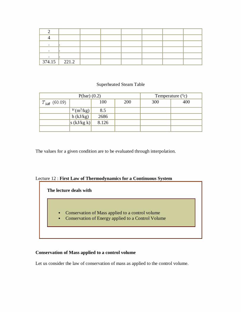
Superheated Steam Table
P(bar) (0.2) Temperature (oc)
100 200 300 400
(m3/kg) 8.5
h (kJ/kg) 2686
s (kJ/kg k) 8.126
The values for a given condition are to be evaluated through interpolation.
Lecture 12 : First Law of Thermodynamics for a Continuous System
The lecture deals with
Conservation of Mass applied to a control volume
Conservation of Energy applied to a Control Volume
Conservation of Mass applied to a control volume
Let us consider the law of conservation of mass as applied to the control volume.
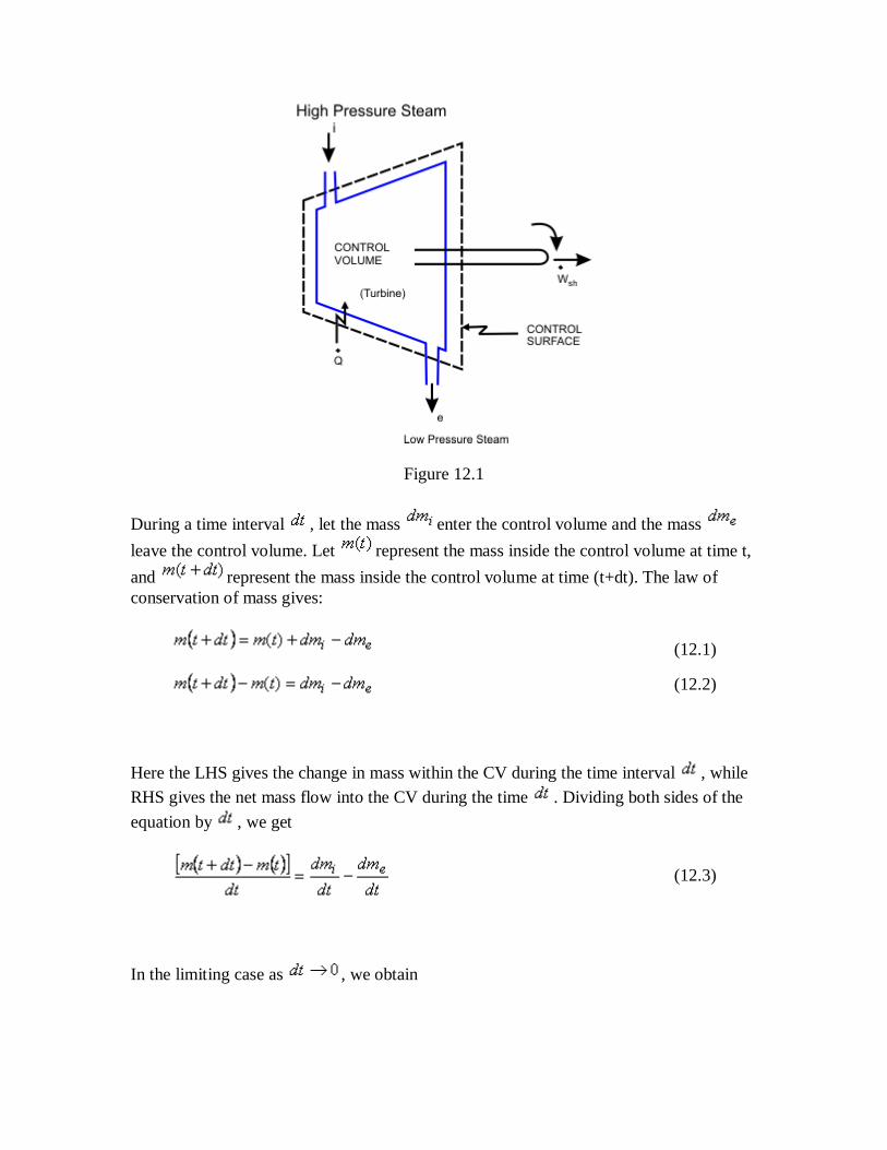
Figure 12.1
During a time interval , let the mass enter the control volume and the mass
leave the control volume. Let represent the mass inside the control volume at time t,
and represent the mass inside the control volume at time (t+dt). The law of
conservation of mass gives:
(12.1)
(12.2)
Here the LHS gives the change in mass within the CV during the time interval , while
RHS gives the net mass flow into the CV during the time . Dividing both sides of the
equation by , we get
(12.3)
In the limiting case as , we obtain

(12.4)
The LHS gives rate of accumulation of mass inside the CV and the RHS has respective
terms giving rate of mass entering the CV and rate of mass leaving the CV.
If the CV has many inlet and exit ports, the equation becomes
(12.5)
(b) Conservation of Energy applied to a Control Volume
Figure 12.2
Let = total mass inside the CV at time .
total mass inside the CV at time .
specific energy of matter inside the control volume at time t.

= specific energy of matter inside the control volume at time .
and = Pressure at the inlet and exit ports, respectively.
and = Flow velocity at the inlet and exit ports, respectively.
and = specific volumes at the inlet and exit ports respectively
and = specific energy of the material at the inlet and exit ports respectively.
= Rate of energy flow as heat into the control volume
= Rate of shaft work done by the control volume
The mass contained in the region A which enters the control volume during the time
interval
The mass contained in the region B which leaves the control volume during the time
interval
From the mass balance, we can write
(12.6)

where is the mass entering the control volume during the differential time . To
accommodate this, the mass inside the control volume has to be compressed such that its
volume decreases by the amount . This is accomplished by the pressure acting
on the material entering the control volume. Therefore, the work done =
Since the mass has to leave the control volume at the exit port, the work done =
,
Energy of the system at time
Energy of the system at time
During the time interval We may account for the following
Energy transferred as heat to the system =
Shaft work done by the system
Energy flow as heat into the control volume and the shaft work delivered by the control
volume are taken as positive. By applying the first law of thermodynamics, we get
(12.7)

or,
(12.8)
or,
(12.9)
In the limiting case,
(12.10)
Where,
and
elevation of the exit and inlet ports above the datum level. The above expression
can now be rearranged as
(12.11)
Rate of energy accumulation = Rate of energy inflow - Rate of energy outflow

Lecture 13 : Steady-state Flow Processes
The lecture contains
Steady State Flow Processes
Application of Steady State Flow Processes
Steady-state Flow Processes
Many of the engineering devices like turbines, compressors, pumps, nozzles, condensers,
heat exchangers etc. operate at steady state conditions. The general expression developed
for the control volume in the earlier lecture can be simplified if steady flow conditions
are assumed.
These are:
The mass flows into the control volume at a constant rate and leaves the control
volume at the same rate. Therefore, there is no accumulation of mass inside the
control volume. Thus, .
or,
(13.1)
The state of the matter at the inlet, exit and at any given point inside the control
volume does not change with respect to time. Therefore,
(13.2)
The rate of energy transfer as heat and work across the control surface is a
constant. constant; constant

With these, the first law for the control volume reduces to the form
(13.3)
Application of Steady-state Flow Processes
(a) Turbine:
Turbine converts enthalpy into useful work. Steam or gas at high temperature and
pressure is allowed to expand through a system of rotors.
Figure 13.1
The change in kinetic and potential energy of steam or gas as it passes through the turbine
can be ignored without introducing much error. Further, if the heat losses from the
turbine are negligible, the first law for this steady state flow reduces to
(13.4)
Therefore, in an adiabatic turbine, the work done per unit mass of the fluid is equal to the
decrease in the enthalpy of the fluid. Here, is positive;
(b) Compressor:
A compressor can be considered as a turbine operating in reverse. Fluid enters the

compressor at a low pressure and emanates at a higher pressure. If the changes in the
kinetic energy and potential energy are ignored, and the energy losses are negligible, then
the first law for this flow process reduces to
(13.5)
In a compressor, is negative. Because the work is being done on the system, .
The work done on the compressor per unit mass of the fluid is equal to the increase in
enthalpy of the fluid. The compressors discharge the fluid with higher enthalpy, i.e, with
higher pressure and temperature.
(c) Nozzle:
A nozzle is primarily used to increase the flow velocity.
Figure 13.2
The first law reduces to
(13.6)
or,
(13.7)
If the inlet velocity is negligible and then otherwise,
.The velocity is increased at the cost of drop in enthalpy. If an

ideal gas is flowing through the nozzle, the exit velocity can be expressed in terms of
inlet and outlet pressure and temperatures by making use of the relations: and
.
Therefore,
(13.8)
From the relations governing adiabatic expansion,
(13.9)
We get,
(13.10)
(d) Diffuser: A diffuser can be thought of as a nozzle in which the direction of flow is
reversed.
Figure 13.3

For an adiabatic diffuser, and are zero and the first law reduces to
(13.11)
The diffuser discharges fluid with higher enthalpy. The velocity of the fluid is
reduced.
(e) Heat Exchangers
Figure 13.4
The figure 13.4 explains the working of a simple heat exchanger. The governing equation
may be modified for multiple entry and multiple exit of the system as
(13.12)
(13.13)
(13.14)
(13.15)

Further, and
(13.16)
is the mass flow rate of cold fluid and is the mass flow rate of hot fluid.
Lecture 14 : Throttling Process
The lecture contains
Throttling Process
Application of Throttling Process
Throttling Process:
The porous plug experiment was designed to measure temperature changes when a fluid
flows steadily through a porous plug which is inserted in a thermally insulated, horizontal
pipe. The apparatus used by Joule and Thomson is shown in Figure 14.1.
Figure 14.1

A gas at pressure and temperature flows continuously through a porous plug in a
tube and emerges into a space which is maintained at a constant pressure . The device
is thermally insulated and kept horizontal. Consider the dotted portion as control volume.
This results in
Therefore, whenever a fluid expands from a region of high pressure to a region of low
pressure through a porous plug, partially opened valve or some obstruction, without
exchanging any energy as heat and work with the surrounding (neglecting, the changes in
PE and KE), the enthalpy of the fluid remains constant, and the fluid is said to have
undergone a throttling process. If the downstream pressure is held at several different
values successively and at each of these is measured, we shall obtain a situation
explained by Figure 14.2.
Figure 14.2
Each plotted point represents a state for which the enthalpy is equal to . If we join all
these points we shall be able to obtain a constant enthalpy line (figure 14.3).

Figure 14.3
Such a plot of P versus yields may also be called isenthalpic curve. The slope of the
isenthalpic curve is called the Joule-Thomson coefficient and given by
The experiments are conducted with different and in order to find out the isenthalpic
curves. A family of isenthalpic curves is shown in Figure 14.4 which is typical of all real
gases.
Figure 14.4
The point at which is called the inversion point. The locus of all the inversion
points is the inversion curve.

In the region left of the inversion curve, . In the throttling process the down
stream pressure is always less than the upstream pressure . Therefore, whenever a
real gas is subjected to throttling, the temperature of the gas decreases if the initial state
lies in the region to the left of the isenthalpic curve. This is explained by a process from
to in Figure 14.4.
To the right of the inversion curve, . If the initial state of gas lies in the region to
the right of the inversion curve, the temperature of the gas increase upon throttling. For
almost all the gases, at ordinary range of pressures and temperature, and the
maximum inversion temperature is above the room temperature. The exceptions are
hydrogen, helium and neon. For hydrogen, the maximum inversion temperature is 200 K
and for helium the maximum inversion temperature is 24 K. If hydrogen is throttled at
room temperature, the temperature of the gas increases. To produce low temperature by
throttling, the initial temperature of hydrogen should be below 200 K. This is usually
accomplished by cooling with liquid nitrogen. Similarly, in the production of liquid
helium by throttling, the initial temperature of helium should be below 24 K. Hence it is
cooled by liquid hydrogen prior to throttling.
Suppose an ideal gas is throttled. Since throttling process is isenthalpic, and for an ideal
gas enthalpy is a function of temperature only, the temperature of an ideal gas does not
change during a throttling process. Hence for an ideal gas.
Applications of Throttling
(a) Refrigeration
The working fluid (called refrigerant) leaving the evaporator as vapour at state 1
undergoes an adiabatic compression in a compressor and leaves as saturated vapour at
state 2. This compressed refrigerant enters a condenser where it rejects heat to the
ambient atmosphere and leaves as a saturated liquid at high pressure at state 3. Then the
liquid refrigerant at high pressure undergoes throttling and leaves as a mixture of liquid
and vapour at low pressure at state 4. During throttling, the liquid vaporizes partially and
its temperature decreases. The cooled refrigerant then passes through an evaporator
where it absorbs energy from the body to be cooled, and leaves as hot vapor at state 1.
Finally, the hot refrigerant vapour goes to the compressor, thus completing a cycle.

Figure 14.5
Applying the first law of thermodynamics to each of the units (control volume) the
following relations are obtained:
Compressor (adiabatic)
Condenser (constant pressure cooling)
Throttling (isenthalpic)
Evaporator (constant pressure heat addition)
The coefficient of performance (COP) of the refrigerator is defined as the ratio of the
energy absorbed at the evaporator to the energy required to perform the task.
(b) Liquefaction of Gases
When a real gas which is initially at a temperature lower than the maximum inversion
temperature is throttled, its temperature decreases. This principle is used by Linde in the
Liquefaction of gases. Refer to figure 14.6 for understanding the operating cycle.

Figure 14.6
The gas is compressed to a high pressure and then cooled at constant pressure in a
counter current heat exchanger with the cold gas which comes from the separator. The
cooled gas is throttled to a low pressure. Thus some amount of gas is converted into the
liquid phase. The two-phase mixture comes to the separator. The liquid is withdrawn and
the cold gas is fed to the heat exchanger. Then the gas enters the compressor along with a
fresh stream of make up gas for liquefaction.

Lecture 15 : Transient Flow Processes
The lecture contains
Transient Flow Processes
Charging of a Cylinder ( Control Volume Analysis)
Discharging of a cylinder (Control Volume Analysis)
Transient Flow Processes
During charging and discharging of cylinders/tanks the condition of the fluid inside the
cylinders/tanks change with time. The rates of inflow and outflow of mass are not
identical and there is accumulation of mass and energy inside the control volume.
Figure 15.1
These processes are transient flow processes. The first law expression for a control
volume is given by
(15.1)

Charging of a Cylinder (control Volume Analysis)
While charging the cylinder from the supply mains, no gas leaves the control
volume, and . No shaft work is done; . Let us ignore the
changes in the kinetic energy and potential energy of the gas during charging
operation. Then it is possible to write from the equation (15.1)
(15.2)
or,
(15.3)
Where, denotes the mass of the gas in the control volume and u denotes the
specific internal energy of the gas inside the control volume at time . It is
assumed that the state of the gas at any instant of time inside the control
volume is uniform. The expression above can be integrated from the start of
the charging operation to the end of the charging operation , to
obtain
(15.4)
The principle of conservation of mass for the charging process reduces to:
(15.5)
Rate of increase of mass in Rate of mass entry
Integration of the above equation over time gives the change of mass in the
control volume during the charging operation
(15.6)

Now in the equation (15.4), the last term on the RHS can be evaluated as
(15.7)
and
(15.8)
Substituting (15.6), (15.7), and (15.8) in (15.4) we get
(15.9)
If the cylinder is initially empty and the filling operation is carried out under
adiabatic conditions the above expression reduces to
(15.10)
If the gas is treated as ideal and
Then,
(15.11)
Where, is the final temperature of the gas in the cylinder and is the ratio
of the specific heats. is the temperature of the gas in supply mains.

Discharging of a cylinder (control volume Analysis)
Consider a tank containing a gas at known conditions of temperature and pressure (figure
15.2).
Figure 15.2
The valve is opened, the gas escapes from the tank and the properties of the gas in the
tank change with respect to time.
Let, pressure of the gas inside the cylinder at
temperature of the gas inside the cylinder at
specific internal energy of the gas inside the cylinder at
and denote corresponding quantities of the gas left in the cylinder after the
discharging operation.
velocity of the escaping gas. From the first law, we can write

(15.12)
No material flows into the cylinder and the potential energy changes can
be ignored. Then
(15.13)
For the discharging process, the conservation of mass gives
(15.14)
Integrating the above equation over time gives
(15.15)
Integration of the governing equation yields
(15.16)
Now the term on the left hand side may be evaluated as
(15.17)
Similarly,
(15.18)

and
(15.19)
Finally invoking (15.17), (15.18) and (15.19) in (15.16) we get
(15.20)
It is assumed that the gas escapes with a uniform velocity V and specific enthalpy h.
Case of an Ideal Gas
Consider a small amount of gas in the cylinder (confined in an imaginary envelope) in the
cylinder as a system.
Figure 15.3
Imagine a situation when gas escapes the cylinder.
The boundary of the system changes continuously and eventually occupies the entire
volume of the cylinder. The gas which is left in the cylinder does not exchange energy in
the form of heat with the surroundings. It undergoes an adiabatic expansion. We can
prove that the gas undergoes a reversible adiabatic expansion.

The general expression is:
(15.21)
We can change the basis of analysis from a control mass to a control volume based
analysis. Under such a situation, Let us consider the cylinder volume as the volume of
interest.
, and ignore the change in KE and PE
(15.22)
From the principle of conservation of mass
(15.23)
Therefore
(15.24)
For a perfect gas, and . Then equation (15.24) can be rewritten as
(15.25)
or,

(15.26)
or,
(15.27)
or,
(15.28)
By integration between final state and initial state
(15.29)
As
(15.30)
or,
(15.31)
Where is the characteristics gas constant
So,
(15.32)
and
(15.33)

Invoking these relations, we get
(15.34)
or,
(15.35)
(15.36)
Therefore the gas that remains in the tank can be considered to have undergone a
reversible adiabatic expansion from the initial pressure to the final pressure .

Lecture 16 :
The lecture contains
Limitations of First Law of Thermodynamics
Heat Engine
Heat Pump
Refrigerator
KELVIN PLANCK STATEMENT
Limitations of First Law of Thermodynamics
The first law of thermodynamics is a law of conservation of energy. It does not specify
the direction of the process. All spontaneous processes processed in one direction only.
The first law of thermodynamics does not deny the feasibility of a process reversing
itself. The first law of thermodynamics does not provide answers to the following
questions.
IS A PARTICULAR PROCESS / REACTION FEASIBLE?
TO WHAT EXTENT DOES THE PROCESS / REACTION PROCEED?
IS COMPLETE CONVERSION OF INTERNAL ENERGY INTO WORK
POSSIBLE?
There exists a law which determines the direction in which a spontaneous process
proceeds. The law, known as the second law of thermodynamics, is a principle of wide
generality and provides answer to the above questions.
It is essential to understand the meaning of the following terms in order to discuss the
second law of thermodynamics:
Thermal reservoir is a large body from which a finite quantity of energy can be
extracted or to which a finite quantity of energy can be added as heat without
changing its temperature.

A source is a thermal reservoir at high temperature from which a heat engine
receives the energy as heat.
A sink is a low temperature thermal reservoir to which a heat engine rejects
energy as heat.
Heat Engine
A heat engine is a device which converts the energy it receives at heat, into work.
It is a cyclically operating device.
It receives energy as heat form a high temperature body, converts part of it into
work and rejects the rest to a low temperature body.
A thermal power plant is an example of a heat engine.
Figure 16.1
Figure 16.1 describes a basic arrangement of a thermal power plant
In the boiler, the working fluid receives a certain amount of heat from the hot
combustion products.
The superheated steam enters a turbine where it undergoes expansion performing
the shaft work .
The low pressure steam enters a condenser where it exchange energy as heat at
constant pressure with the cooling water and emerges as the condensate. The
condensate rejects a certain amount of heat to the cooling water.
The low pressure condensate from the condenser enters the pump. Work is
done on the pump to elevate the condensate to the boiler pressure and return it to
the boiler.
In the above example,
Work done by the system
Energy absorbed as heat by the system
Energy rejected as heat by the system
According to first law of thermodynamics, the heat and work interaction are related by
the equation.
(16.1)
Finally, the thermal efficiency of a heat engine can be expressed as
or,
(16.2)

Heat Pump
Heat Pump is cyclically operating device which absorbs energy form a low temperature
reservoir and reject energy as heat to a high temperature reservoir when work is
performed on the device. Its objective is to reject energy as heat to a high temperature
body (space heating in winter). The atmosphere acts as the low temperature reservoir.
Refrigerator
A refrigerator is a cyclically operating device which absorbs energy as heat from a low
temperature body and rejects energy as heat to a high temperature body when work is
performed on the device. The objective of this device is to refrigerate a body at low
temperature. Usually it uses atmosphere as the high temperature reservoir.
Figure 16.2
Refer to figure 16.2. Let and represents the amount of energy absorbed as heat
from the low temperature reservoir and the energy rejected as heat to the high
temperature reservoir respectively, Let W be the work done on the device to accomplish
the task.
(16.3)
Therefore,

(16.4)
and
(16.5)
Heat engine and the refrigerator (/heat pump) can be represented as shown in Figure 16.2.
The efficiency of a heat engine is given by
(16.6)
since (heat) transferred to the system cannot be completely converted to
work in a cycle. Therefore is less than unity. A heat engine can never be 100 efficient.
Therefore i.e., there has always to be a heat rejection. Thus a heat engine has to
exchange heat with two reservoirs, the source and the sink. This experience leads to the
proposition of the second law of thermodynamics which has been stated in several
different ways.
KELVIN PLANCK STATEMENT
It is impossible to construct a cyclically operating device such that it produces no other
effect than the absorption of energy as heat from a single thermal reservoir and performs
an equivalent amount of work.
The only option then is that the engine converts part of the energy it receives as heat into
work and rejects the rest to another thermal reservoir the temperature of which is less
than the temperature of the source. Two thermal reservoirs, one of high temperature
(source), from which the working fluid receives energy as heat, and the other of low
temperature (sink), to which the working fluid rejects energy as heat, are needed for a
heat engine. Once the heat engine rejects a part of the energy it receives, its efficiency
becomes less than one. Thus the Kelvin Planck statement further implies that no heat
engine can have a thermal efficiency of one (hundred percent). This does not violate the
first law of thermodynamics either.

Lecture 17 :
The lecture contains
Kelvin - Planck Statement (Continued)
Clausius Statement of the Second Law
Kelvin - Planck Statement (continued)
Second law restricts the thermal efficiency of a heat engine to less than one. It stipulates
that some portion of the energy absorbed as heat from a source must always be rejected to
a low temperature sink.
Wilhelm Ostwald introduced the concept of perpetual motion machine of the second kind
(PMMSK or PMM2), that is, of a device which would perform work solely by absorbing
energy as heat from a body. Such a device does not violate the first law of
thermodynamics.
Figure 17.1
A PMMSK is a hypothetical device (Figure 17.1) which working cyclically, receives
energy as heat from a single thermal reservoir, and delivers as equivalent amount of
work. The Kelvin-Planck statement of the second law tells us that it is impossible to
constructs a perpetual motion machine of the second kind.
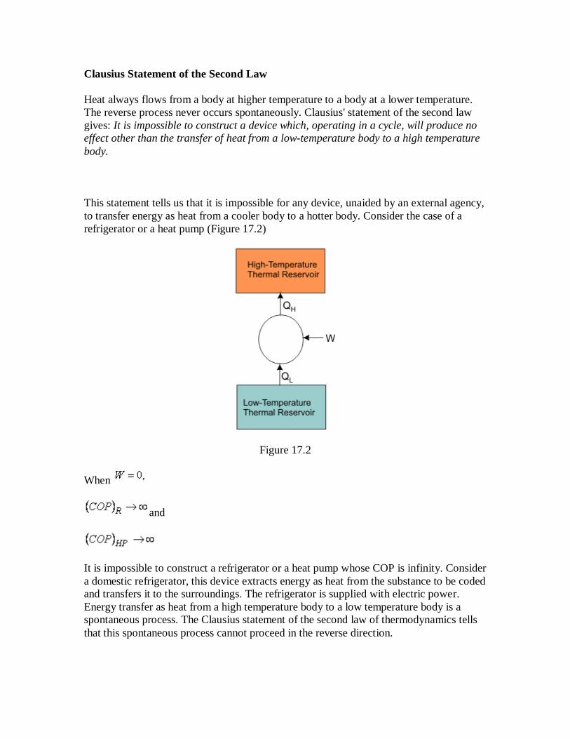
Clausius Statement of the Second Law
Heat always flows from a body at higher temperature to a body at a lower temperature.
The reverse process never occurs spontaneously. Clausius' statement of the second law
gives: It is impossible to construct a device which, operating in a cycle, will produce no
effect other than the transfer of heat from a low-temperature body to a high temperature
body.
This statement tells us that it is impossible for any device, unaided by an external agency,
to transfer energy as heat from a cooler body to a hotter body. Consider the case of a
refrigerator or a heat pump (Figure 17.2)
Figure 17.2
When
and
It is impossible to construct a refrigerator or a heat pump whose COP is infinity. Consider
a domestic refrigerator, this device extracts energy as heat from the substance to be coded
and transfers it to the surroundings. The refrigerator is supplied with electric power.
Energy transfer as heat from a high temperature body to a low temperature body is a
spontaneous process. The Clausius statement of the second law of thermodynamics tells
that this spontaneous process cannot proceed in the reverse direction.

Apparently, the Kelvin Planck statement and the Clausius statement of the second law of
thermodynamics are altogether different. They are not ! Instead, they are equivalent. A
violation of Kelvin Planck statement leads to a violation of the Clausis statement too and
vice-versa.
Clausius Statement of the Second Law (contd...)
Let us suppose that the Kelven Planck statement is incorrect.
Figure 17.3
Refer to Figure 17.3 that is, it is possible to construct a device I which, working
cyclically, absorbs energy a heat from a source at temperature and performs an
equivalent amount of work . Next consider a device II which absorbs
amount of energy from a low temperature body at and delivers energy as heat to a
high temperature reservoir at . To accomplish this, work is done on the device. The
device II does not violate the Clausius statement. For device II, we can write
. Now combine I and II. The work delivered by device I is used by device,
II.
Then
(17.1)
(17.2)
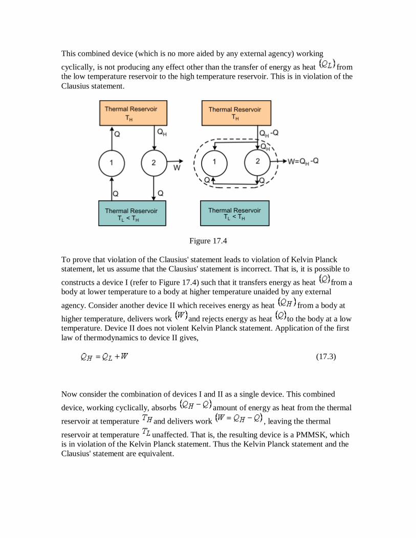
This combined device (which is no more aided by any external agency) working
cyclically, is not producing any effect other than the transfer of energy as heat from
the low temperature reservoir to the high temperature reservoir. This is in violation of the
Clausius statement.
Figure 17.4
To prove that violation of the Clausius' statement leads to violation of Kelvin Planck
statement, let us assume that the Clausius' statement is incorrect. That is, it is possible to
constructs a device I (refer to Figure 17.4) such that it transfers energy as heat from a
body at lower temperature to a body at higher temperature unaided by any external
agency. Consider another device II which receives energy as heat from a body at
higher temperature, delivers work and rejects energy as heat to the body at a low
temperature. Device II does not violent Kelvin Planck statement. Application of the first
law of thermodynamics to device II gives,
(17.3)
Now consider the combination of devices I and II as a single device. This combined
device, working cyclically, absorbs amount of energy as heat from the thermal
reservoir at temperature and delivers work , leaving the thermal
reservoir at temperature unaffected. That is, the resulting device is a PMMSK, which
is in violation of the Kelvin Planck statement. Thus the Kelvin Planck statement and the
Clausius' statement are equivalent.

Lecture 18 : Reversibility, Irreversibility and Carnot cycle
The lecture contains
Introduction
Irreversible Processes
Reversible Processes
Carnot Cycle
Carnot Engine
Reversibility, Irreversibility and Carnot cycle
The second law of thermodynamics distinguishes between reversible and irreversible
processes.
If a process can proceed in either direction without violating the second law of
thermodynamics, it is reversible process. A reversible process is carried out
infinitely slowly with an infinitesimal gradient, so that every state passed through
by the system is an equilibrium state. So, a reversible process is a quasi-static
process which can proceed in either direction.
Given a process, if the attempt to reverse its direction leads to a violation of the
second law of thermodynamics, then the given process is irreversible.
Any natural process carried out with a finite gradient is an irreversible process . A
reversible process which consists of a succession of equilibrium states, is an idealized
hypothetical process, approached only as a limit. It is said to be an asymptote to reality,
All spontaneous processes are irreversible.
rreversible Processes
The example of irreversible processes are: Motion with friction, free expansion,
Expansion/ compression with finite pressure difference, Energy transfer as heat with
finite , Mixing of matter at different states, Mixing of non-identical gases.

Reversible Processes
The processes which can be idealized as reversible are: Motion without friction,
Expansion/compression with infinitesimal pressure difference, Energy transfer as heat
with infinitesimal temperature difference.
Carnot Cycle
A French engineer Sadi Carnot was the first to introduce the idea of reversible cycle.
From the second law, it has been observed that the efficiency of a heat engine is less than
unity. If the efficiency of heat engine is less than unity, what is the maximum efficiency
of a heat engine? This can be answered by considering the Carnot cycle. The concept of
carnot cycle is executed via Carnot engine.
Carnot Engine
Let us consider the operation of a hypothetical engine which employs the Carnot cycle.
The Carnot engine consists of a cylinder-piston assembly in which a certain amount of
gas(working fluid) is enclosed. Refer to Figure 18.1 representing the Carnot cycle.
Figure 18.1

Reversible Isothermal Heat Addition
In the first process, the cylinder head is brought into contact with a source at temperature
. The gas inside the cylinder is also at temperature . The gas expands reversibly and
isothermally . During this process, the system absorbs energy as heat from the
source. The system changes its state from 1 to 2 on the diagram.
(18.1)
where, for an ideal gas,
Reversible Adiabatic Expansion
In the second process, the cylinder head is insulated and the gas is allowed to expand till
its temperature is equal to the sink temperature . The system thus reaches state 3. This
is a reversible adiabatic process.
(18.2)
Reversible Isothermal Heat Rejection
In the next process, the system is brought into contact with the sink which is at a
temperature . The heat leaves the system and the internal energy further decreases
(18.3)
where, only for an ideal gas,
Through a reversible isothermal process the system reaches state 4.

Reversible Adiabatic Compression
In the next process, the gas is compressed reversibly and adiabatically till it reaches the
initial state 1, thus, completing the cycle.
(18.4)
Summing up all the processes, one can write
or,
The thermal efficiency,
(18.5)
Efficiency of Carnot Engine Using Ideal Gas
1-2: A reversible isothermal expansion with heat addition

(18.6)
2-3: A reversible adiabatic expansion
(18.7)
3-4: A reversible isothermal compression with heat rejection
(18.8)
4-1: A reversible adiabatic compression
(18.9)
(18.10)
Energy absorbed as heat
(18.11)
Thermal efficiency,
(18.12)

Here, for the ideal gases we can write
Also,
or,
(18.13)
So,
(18.14)

Lecture 19 : Carnot's Principles (Theorems)
The lecture contains
Carnot's Principle I
Carnot's Principle II
Two consequences of the second law of thermodynamics are will known as Carnot's
principles.
Principle I:
No heat engine operating between the two given thermal reservoirs, each of which is
maintained at a constant temperature, can be more efficient than a reversible engine
operating between the same two thermal reservoirs. Refer to Figure 19.1
Figure 19.1
Let two heat engines and operate between the given source at temperature and
the given sink at temperature as shown.

Let be any heat engine and any reversible heat engine. We are to prove that the
efficiency of is more than that of . Let us assume that it is not true . Let
the rates of working of the engines be such that
(19.1)
Since,
(19.2)
Now let the direction of be reversed.
Figure 19.2
Refer to Figure 19.2. Since is a reversible heat engine, the magnitudes of heat and
work quantities will remain the same, but their directions will be reversed as shown.
Since some part of (equal to ) may be fed to drive the reversed heat
engine . Since, , the heat discharged by the reversed may be
supplied to .

The source may, therefore, be eliminated. The net result is that and together
constitute a heat engine which, operating in a cycle, produces net work , while
exchanging heat with a single reservoir at .
This violates the Kelvin-Planck statement of the second law . Hence the assumption
is wrong.
Therefore,
(19.3)
Principle II:
All reversible heat engines operating between the two given thermal reservoirs have the
same efficiency. The efficiency of reversible heat engine does not depend on the working
fluid, it depends only on the temperature of the reservoirs between which it operates.
To prove the proposition, let us assume that the efficiency of the reversible engine is
greater than the efficiency of the reversible engine .
Figure 19.3
Refer to Figure 19.3. The engine absorbs energy as heat from the constant
temperature thermal reservoir at , does work and rejects energy as heat to the
reservoir at . The engine absorbs energy as heat from the reservoir at , does

work and rejects energy as heat to the reservoir at . Then and
(19.4)
and
(19.5)
By assumption,
Then,
(19.6)
Therefore,
Since is a reversible engine, it can be made to execute the cycle in the reversed order.
That is, when work is performed on the device, it absorbs energy as heat, from
the reservoir at and rejects energy as heat to the reservoir at . Since, ,
can be run as a heat pump utilizing part of the work done by . The combination
of the two devices is also shown in the figure.
The net work done by the device is given by
(19.7)
The resulting device absorbs energy as heat from the reservoir at .
Does not require any interaction with the second reservoir.
Delivers an equivalent amount of work.
This is in violation of the Kelvin-Planck statement of the second law of thermodynamics.
Hence the assumption that , is incorrect. Therefore,
(19.8)

Nov let us assume that the reversible engine is more efficient then the reversible
engine . Then the reversible engine can be run as a heat pump, utilizing the part of
the work done by . By following the similar argument as the earlier case, we can
arrive at the result that,
(19.9)
Hence, it can be concluded that
(19.10)
Stated in works: All reversible engines operating between the two given thermal
reservoirs have the same efficiency.
Lecture 20 : Thermodynamic Temperature Scale
The lecture contains
Thermodynamic Temperature Scale
Thermodynamic Temperature Scale
A temperature scale, which does not depend on the thermodynamic property of the
substance can be established by making use of the fact that the efficiency of a reversible
heat engine does not depend on the nature of the nature of the working fluid but depends
only upon the temperature of the reservoirs between which it operates. The establishment
of thermodynamic temperature scale is also a consequence of the second law of
thermodynamics. Refer to Figure 20.1.

Figure 20.1
Let, and be the isotherms. Let the two reversible adiabatics intersect the three
isotherms. Let the reversible engine 1 absorb energy as heat, from the reservoir at
and reject energy as heat, to the reservoir at . Let the reversible engine 2 absorb
energy as heat, from the reservoir and reject heat, to the reservoir at . Let
and represent the work done by engines 1 and 2, respectively. Let a third Carnot
engine absorb energy as heat from the reservoir at and reject energy as heat to
the reservoir at . The work done by the engine is given by
(20.1)
Also,
(20.2)
or,
(20.3)
or,
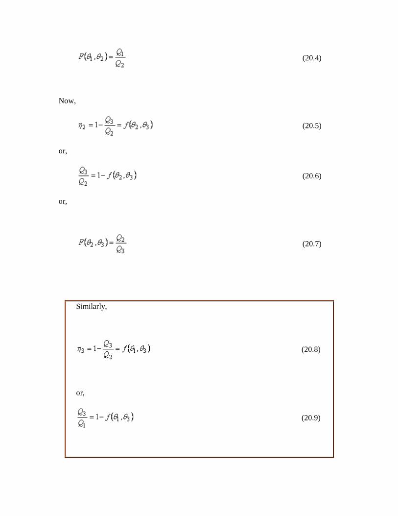
(20.4)
Now,
(20.5)
or,
(20.6)
or,
(20.7)
Similarly,
(20.8)
or,
(20.9)
or,
(20.10)
Then,
(20.11)
or,
(20.12)
In the above equation, does not appear on the left hand side. Therefore, on
the right hand side, the dependence on should cancel out. Hence, the
nature of function F is such that,
(20.13)
Then,
(20.14)
Therefore,
or,
(20.15)
So,

(20.16)
There is no further restriction on the function. The choice of the function
now defines the temperature scale of interest.
If we choose
(20.17)
(20.18)
or,
(20.19)
Recall,
(20.20)
or,
(20.21)
The efficiency of no heat engine can be greater than one. The lowest possible
temperature in this scale is zero .

Figure 20.2
Refer to Figure 20.2. Hence it is called the absolute temperature scale. The
absolute temperature scale is also known as Kelvin temperature scale. In
defining the Kelvin temperature scale also, the triple point of water is taken
as the standard reference point. For a Carnot engine operating between
reservoirs at temperature and being the triple point of water
arbitrarily assigned the value of ,
or,
(20.22)
If this equation is compared with the perfect gas temperature scale
[remember, we have obtained where , it is
seen that in the Kelvin Scale Q plays the role of the thermometric property.
Consider a Carnot engine using a perfect gas as a working fluid. Let the high temperature
reservoir be at and low temperature reservoir be at
(20.23)
or,
But the absolute temperature scale is defined by the relation
(20.24)
Therefore,
Since the numerical value assigned to the triple point of water can be chosen
to be same for both the perfect gas scale and the absolute temperature scale, .
Hereafter, the common symbol may be used to represent the temperature.
