engine block alignment with the l-706 laser - ess power of supply/laser tools/laser bore... ·...
TRANSCRIPT

Designed for high-accuracy bore alignments, the L-706 offers the most accurate, yet easy to use laser alignment system. With high resolution, capability to measure a wide range of bore diameters, and our patented A-514 self-centering bore adapters, the L-706 is the best bore alignment system on the market. The L-706 also offers a variety of target options, including self-centering, see-through, 2-axis and 4-axis targets, hand-held readouts, and Windows®-based software to display and analyze alignment data. The system handles a wide variety of bore alignment applications, including bar-turning machines, bore straightness checks for compressor bores, engine-block crankshaft bore alignment, stern tube alignment, tail rotor bearing alignment for helicopters, and tube support plate bores for heat exchangers.
The L-706 Bore Laser System L-706 Bore Laser The L-706 Bore Laser is a battery-operated, visible light laser that mounts magnetically in a bore fixture or mounting fixture. It is suitable for almost all bore applications. The laser has two mounting surfaces: 0.7498" (19.04 mm) and 2.2498" (57.14 mm). The laser beam is centered to both mounting ODs to within .0003" (0.08 mm). The L-706 Laser is equipped with fine angular adjustments necessary to set the laser beam to the center of the far reference target. It is used for applications up to 110 feet (33 meters). Fast Setup and Even Faster Measurements With simplified fixturing and self-centering targets, the system can be set up in as little as 15 minutes. Since it literally takes less than a minute to insert the target/adapter into a bore and take a measurement, bore straightness data can be taken and analyzed in 30 minutes or less in most cases. This means even the longest bore application can be measured in just minutes versus hours for optics, tight wire or other laser systems. Nothing is faster than the L-706 Bore Alignment System!
5 Ye Olde Road, Danbury, CT 06810 • Phone: (800) 826-6185 • Fax: (203) 730-4611
E-mail: [email protected] • Internet: http://www.hamarlaser.com
Application Notes L-706 Applications • Engine Crankcase Bores • Compressor Bores • Cylinder Bores • Stern Tube Shaft Bearings • Tube Support Plate Bores
Engine Block Alignment with the L-706 Laser
ALIGN WITH THE BEST

2
Patented Self-Centering Target & Adapters – The Key to the System The A-512 2-Axis Bore Target has a 10x10 mm PSD and is designed specifically for our A-514 line of self-centering bore adapters. This unique feature allows our target to be inserted into a bore without any mechanical setup, such as bore sweeping or the need to rotate the target to determine mounting errors (a common problem with most other systems). The target is concentric to its housing to within .0003" (0.0075 mm). When used with the A-514 adapters, the sensor is centered to the bore within .0006" (0.015mm). Another unique feature of our A-514 adapters is they can handle a fairly large range of bore diameter changes of up to .040" (1 mm), so bore diameter changes do not affect the accuracy of bore alignment measurements. High Resolution Angular Adjustments Micrometers provide high-resolution angular adjustment of laser beam to steer the laser to zero out the reference target (detector) during setup. The L-706 has an angular adjustment resolution of .001" 100 feet (0.025 mm in 30 meters). Each laser has a NOMINAL setting for both the Vertical and Horizontal micrometers that sets the laser square to the mounting faces and in the center of the adjustment range. 4-Axis Laser-Mounting Fixture for Vertical and Horizontal Surfaces The L-111 Laser Stand and L-102 Beam Translator provide 4-axis adjustment capability to quickly align the laser beam to any two bores for alignment checks and for installing boring-bar bearings. The fixture can be mounted either on the face of a bore or on an instrument stand. System Handles Large Range of Bores Any bore, from 3.75" (92.25 mm) up to 50" (1,270 mm) or more, can easily be measured with our L-706 Bore Laser System. The system offers three bore adapters and a leg-setting gage to set the adapters to the nominal bore ID. We even offer bore targets that can measure bore alignment down to .70" (18 mm). High Measurement Resolution and Accuracy When used with our R-1307 Readouts and Bore9 Software, the L-706 system provides a resolution of .00002" (0.0005 mm). Under good environmental conditions, the L-706 Laser is accurate to .040" (0.1 mm) over the whole 100' (30 M) range. By carefully following the NORMIN procedure, accuracies of .0003" (0.0075 mm) in 10 feet (3.1 meters) can be achieved. Measure Bore Angle in Seconds To check for bore angle relative to the centerline, just take a measurement at the front or back of the bore and any difference shows the angle. Adjust the front and back of the bore to read zero and it’s aligned! Also, with our unique design, our target only needs a few inches of bore width to take a measurement. T-218 Target Measures Bore Diameter Change The T-218 2-Axis Universal Target and T-225L Large Bore Flange are used to measure the bore diameter change from a nominal measurement. Simply measure one of the bores for a reference diameter and then insert the T-218/T-225L into the bore. Take two measurements, one in the normal orientation and one in the inverted. Bore9 does the math to determine the difference in bore diameter from the nominal measurement. This is very useful as a final check of newly machined bores.
Cross section of A-512 Target and A-514 Adapter in bore
L-706 in L-111 Laser Stand and L-102 Beam Translator
A-512 Target and A-514 Self-Centering Bore Adapter mounted in a shaft bearing

3
Model A-512 2-Axis Self-Centering Target The A-512 Target unit is comprised of a stainless steel housing, PSD sensor and insertion handle. The target is inserted into the A-514 Self-Centering Bore Adapters and together they are inserted into a bore to measure the straightness. The effective cell range is ± .100" (2.5 mm), and changes in the x and y axis positions of the target can be displayed on a digital readout with a resolution of .0001" or 0.001 mm. 2.2495" Mounting Diameter Fits into Boring Bar Bearings for Quick QC The L-706 Laser has been designed with a standard boring-bar diameter of 2.2495" (57.137 mm). This means the laser can be inserted directly into bearings after machining for a quick quality control bore straightness check when using our A-512/A-514 Self-Centering Bore Target and Adapters. Live Alignment Data Saves Even More Time As with all of our laser alignment systems, the A-512 Bore Target provides live alignment data via our R-1307 readouts. This means once the target is installed in a bore and you are ready to align it, you just watch the readout continuously update as you adjust the bore, supporting pillow blocks or bearing sleeves. When the readings are zero, you’re done! Wireless Data Downloading and Transfer For long-distance applications, the R-1307 Readout can be configured with a 2.4GHz Zigbee® radio and transmit its data up to 400 feet (120 M) to a second R-1307, which is very useful when bucking-in (setting up) the laser to reference targets that are at distances greater than 15 feet, or it can also be received by the A-910-2.4ZB Computer Interface for automatic downloading into our Bore9 Software. Simple Readouts, Optional Software The L-706 Bore Alignment System comes with simple H & V axis readouts that are extremely easy to use. There is no complicated software to learn in order to use the system, which minimizes training requirements. For those who want to document the alignment and produce a report, there is no easier bore alignment program to use than our Bore9 software.
Bore9 Step 5: Results Screen
A-512 2-Axis Self-Centering Target
R-1307 Readout
L-705 Mounted in Climax Boring Bar Bearing

4
A-514 Self-Centering Bore Adapters for the A-512 Target The A-514 self-centering laser and bore adapters accurately and quickly position the laser and target on the bore centerline. The adapters have adjustable legs that allow them to be used for bore diameters ranging from 3.75" (95 mm) to 40" (1M). Three sizes are available, as follows: • A-514A for bores from 3.75" (95 mm) to 6.75" (172 mm) • A-514B for bores from 6.5" (165 mm) to 17.5" (445 mm) • A-514C for bores from 17.0" (432 mm) to 40.0" (1 M) The A-514GS and A-514GL Leg-Setting Gage The gages are used to set the A-514 Adapter legs to the correct bore diameter. The gages are available in two sizes, depending on the size of the bore being measured. The A-514GS is used with the small (A-514A) or medium (A-514B) bore adapters. The A-514GL can be used for all three adapters and must be purchased if using the large bore adapter. Recommended System Configuration • L-706 Long Distance Bore Laser • L-111 Laser Adjustment Stand • L-102 2-Axis Laser Beam Translation Fixture • A-512 2-Axis Bore Target • A-514A Small-Bore, Self-Centering Adapter for 3.5" to 6.75" diameter bores • A-514B Medium-Bore, Self-Centering Adapter for 6.5"- 17.5" diameter bores • A-514GS Small Leg-Setting Gage for A-514 A and B Adapters • R-1307B-2.4ZB 2-Axis Combination Readout • A-814 Shipping Case Optional Accessories Bore-Diameter Measuring Accessories • T-218 2-Axis Universal See-Through Target • T-225L Large Bore Flange for T-218 Target Bore Alignment Software Accessories • A-910-2.4ZB Wireless Data Receiver • S-1403 Bore9 Software for Windows • T-231AL 25' Target Extension Cable Laser Mounting Accessories • L-106 Instrument Stand • L-111FM Face Mount Accessory for L-111
to extend bore diameter to 32" (813 mm) Large-Bore Targets and Adapter Accessories • A-514C Large-Bore, Self-Centering Adapter
for 17" to 40" diameter bores • A-514GL Large Let-Setting Gage for A-514
A, B and C Adapters • A-514CXL X-Large Bore Self-Centering
Adapter for 17" to 50" diameter bores • A-510 2-Axis Bore Target Small-Bore Targets and Adapter Accessories • A-510 2-Axis Bore Target • A-510STA Self-Centering Adapter Hub • A-510LTA Self-Centering Adapter Hub for Large Bores • M-705CL Set of 4 Customized Legs for A-510STA • A-510SM Customized, 2-Axis, Small-Bore Target and Adapter
A-514 Self-Centering Bore Adapters for the A-512 Target and A-514 GS/A-514GL Leg-Setting Gage

5
How the Alignment System Works – Line Boring Machinery General Setup To perform alignments, the L-706 laser is mounted in the L-111 Laser Stand and the L-102 Laser Beam Translator is attached. The L-111 has coarse angular adjustment capabilities and the L-102 can translate (move) the laser beam up/down and left/right without changing the angle. The entire assembly is then mounted either on an instrument stand near the first reference bore or on the face of the bore. The A-512/A-514 target/adapter is placed in the first bore and the L-102 Beam Translator is adjusted to center the laser beam to the target. The target is then moved to the far reference bore and the angular adjustments are used to tilt the laser to the center of the target. This process is repeated until the target reads zero at both locations. The laser is now parallel to the end reference bores and the target can be moved to (or a second target can be placed in) the inner bores for alignment checks. In addition, boring-bar bearings can be installed and aligned using our T-218 Bore Alignment Target, which fits directly into the bearing.

6
How the A-512 Target and A-514 Adapters Work The A-512 Target is designed so that the PSD is centered axially between the four feet of the A-514 Adapter, two of which are offset axially from the other two. This, in effect, puts the PSD on the pivot point of the adapter and allows the angle of incidence to the laser beam to vary by up to 45º. This means even if the bore diameter changes, the A-514 will still self-center giving an accurate measurement of the bore's alignment. To insert the target into the bore, attach the handle to the target and tip the target forward, which allows it to easily slide into the bore. Release the handle/insertion pole and the target/adapter "jam" into the bore, finding the center automatically. The weight of the handle keeps the target centered in the bore.
How the A-512 and A-514 Self-Centering Adapters Work
A-512/A-514 Target & Adapter Adapter OD = Nominal Bore ID
Bore ID > Nominal ID Target Tilts Forward
PSD Is Still Centered
Bore ID < Nominal ID Target Tilts Back
PSD Is Still Centered
The laser hits a position-sensing detector (PSD), which creates an electrical signal representing the position of the center of energy of the laser beam. This signal is converted into a calibrated digital reading using a variety of hand-held readouts or computer interfaces for use with our software.
7
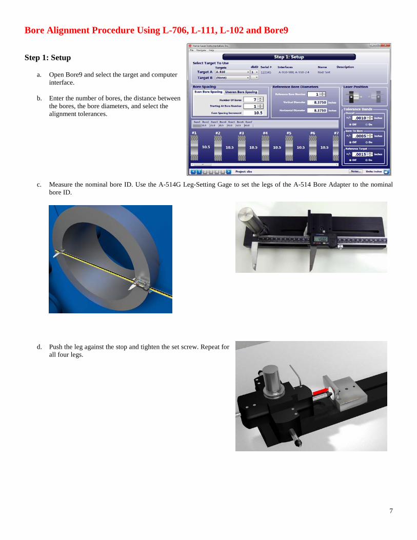
Bore Alignment Procedure Using L-706, L-111, L-102 and Bore9 Step 1: Setup
a. Open Bore9 and select the target and computer interface.
b. Enter the number of bores, the distance between
the bores, the bore diameters, and select the alignment tolerances.
c. Measure the nominal bore ID. Use the A-514G Leg-Setting Gage to set the legs of the A-514 Bore Adapter to the nominal bore ID.
d. Push the leg against the stop and tighten the set screw. Repeat for all four legs.
8
e. Insert the A-512 into the A-514 Adapter and insert them into the near bore, making sure the adapter's level vial is level.
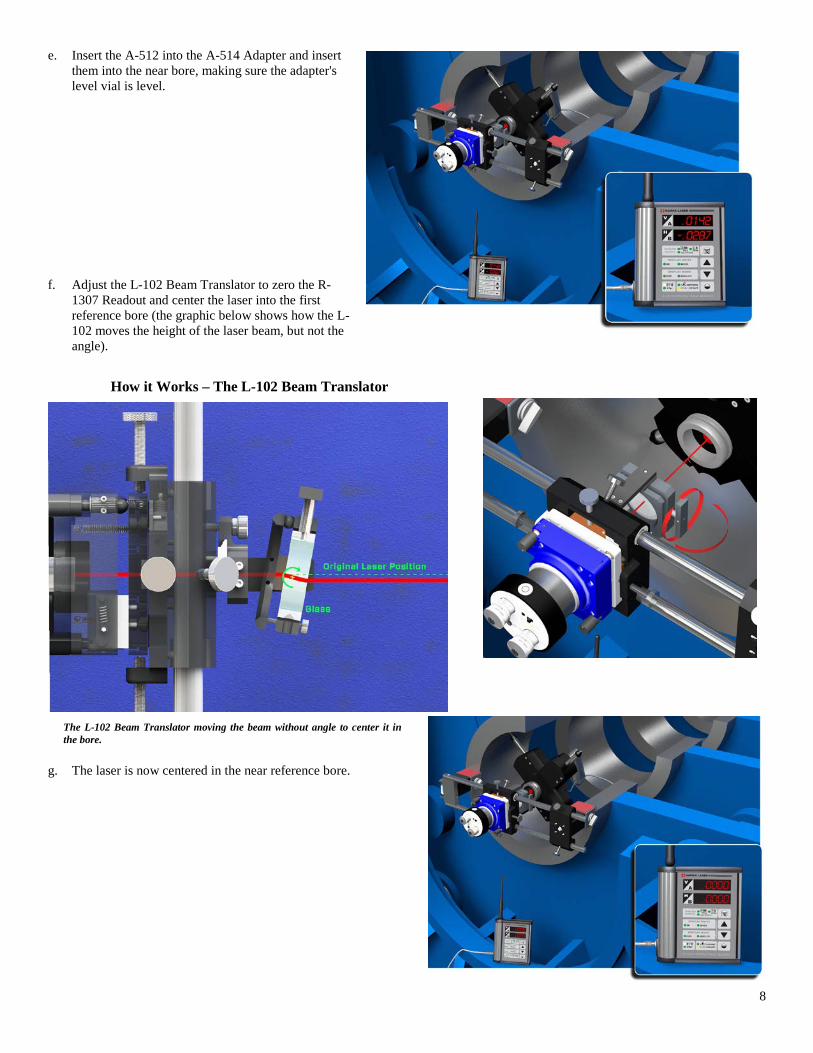
f. Adjust the L-102 Beam Translator to zero the R-1307 Readout and center the laser into the first reference bore (the graphic below shows how the L-102 moves the height of the laser beam, but not the angle).
g. The laser is now centered in the near reference bore.
How it Works – The L-102 Beam Translator
The L-102 Beam Translator moving the beam without angle to center it in the bore.

9
Step 2: Remove Target Mounting Error (optional) Note: Step 3: Remove Target Mounting Error of the Bore9 program may be skipped if measuring bore straightness only, or if aligning bores to .0005" (0.013 mm) or less. Press Record to record data for the target in the NORMAL position. Rotate the target 180 degrees (INVERTED position) and reinsert into the near bore. Press Record to record data for the target in the INVERTED position. Rotate target 180 degrees again back to the NORMAL position and reinsert into the near bore. The TSCE Mounting Error Offset is calculated and applied to each target reading. This removes any remaining centering errors in the target and adapter.
Step 3: Laser Buckin a. Follow the on-screen instructions to enter distances
from the laser to the near bore (D1) and from the near bore to the far bore (D2). If needed, insert the target into the near bore and re-adjust the L-102 to zero the display and center the laser into the bore. Press Record to record data for the near bore.
Step 3: Enter distances
Step 3: Results data showing near point recorded
Step 3: Results data showing far point recorded and set point calculation

10
b. Move the target to the far bore and press Record. A
calculation of the laser set point will be made to aid the laser setup and offsets will be applied to on-screen live data.
c. With buckin offsets applied in the Bore9 software,
steer the laser using the Pitch and Yaw knobs (angular adjustment) on the L-706 until the H and V displays are zero.
d. Repeat the process to confirm zero at both end bores.
The laser is now “bucked in” (concentric) to the centerline of the near and far reference bores.

11
Step 4: Record Data a. Move the target to the first bore you want to measure for
alignment and press Record. Continue moving the target to each bore until all data is taken.

12
Step 5: Results a. Step 5: Results displays a graph of the results and a summary of the alignment.

13
Bore9 Sample Report