engine - lecknerjosh.leckner.us/supra-manual/mechanical.pdf · engine mechanical preparation sst...
TRANSCRIPT

ENGINE
EG–1

EG–2

ENGINE MECHANICALPREPARATIONSST (SPECIAL SERVICE TOOLS)
09201–10000 Valve Guide Bushing Remover &Replacer Set
(09201–01060) Valve Guide Bushing Remover &Replacer 6
09202–70010 Valve Spring Compressor
09213–70010 Crankshaft Pulley Holding Tool
09222–30010 Connecting Rod Bushing Remover& Replacer
09223–15030 Oil Seal & Bearing Replacer Crankshaft rear oil seal
09248–55040 Valve Clearance Adjust Tool Set
(09248–05410) Valve Lifter Press
(09248–05420) Valve Lifter Stopper
09301–00110 Clutch Guide Tool 2JZ–GE M/T
09316–60010 Transmission & Transfer BearingReplacer
(09316–00010) Replacer Pipe Crankshaft front oil sealCamshaft oil seal
–ENGINE ENGINE MECHANICALEG–3

(09316–00050) Replacer “D”
09330–00021 Companion Flange Holding Tool
09608–30022 Front Hub Bearing Replacer Set
(09608–05010) Handle
09816–30010 Oil Pressure Switch Socket
09843–18020 Diagnosis Check Wire
09950–50010 Puller C Set
(09951–05010) Hanger 150
(09952–05010) Slide Arm
(09953–05020) Center Bolt 150
(09954–05010) Claw No.1
(09954–05030) Claw No.3
09960–10010 Variable Pin Wrench Set
(09962–01000) Variable Pin Wrench Arm Assy Camshaft timing pulley
Camshaft pulley
Crankshaft timing pulley
Crankshaft pulleyCrankshaft timing pulley
Crankshaft pulleyCrankshaft timing pulley
Crankshaft pulleyCrankshaft timing pulley
Knock sensorOil pressure switch
Crankshaft rear oil sealValve guide bushing
Crankshaft pulley
Camshaft oil seal
EG–4–ENGINE ENGINE MECHANICAL

(09963–01000) Pin 10 Camshaft timing pulley
RECOMMENDED TOOLS
Cylinder head bolt
A/C compressor stud bolt
For suspending engine
09040–00010 Hexagon Wrench Set �
09043–50100 Bi–hexagon Wrench 10 mm �
09044–00020 Torx Socket E10 �
09082–00050 TOYOTA Electrical Tester Set
09090–04010 Engine Sling Device �
09200–00010 Engine Adjust Kit �
09258–00030 Hose Plug Set �
�
EQUIPMENTÑÑÑÑÑÑÑÑÑÑÑÑÑÑÑÑÑÑÑÑÑÑÑÑÑÑÑÑÑÑÑÑÑÑÑÑÑÑÑÑÑÑÑÑÑÑÑÑÑÑ
Caliper gauge ÑÑÑÑÑÑÑÑÑÑÑÑÑÑÑÑÑÑÑÑÑÑÑÑÑÑÑÑÑÑÑÑÑÑÑÑÑÑÑÑÑÑÑÑÑÑÑÑÑ
ÑÑÑÑÑÑÑÑÑÑÑÑÑÑÑÑÑÑÑÑÑÑÑÑÑCO/HC meter ÑÑÑÑÑÑÑÑÑÑÑÑ
ÑÑÑÑÑÑÑÑÑÑÑÑÑÑÑÑÑÑÑÑÑÑÑÑÑÑÑÑÑÑÑÑÑÑÑÑÑÑÑÑÑÑÑÑÑÑÑÑÑÑÑÑÑÑÑÑÑÑÑÑÑÑÑÑÑÑÑÑÑÑÑÑÑÑÑÑÑÑÑÑÑÑÑÑÑÑÑ
Compression gaugeÑÑÑÑÑÑÑÑÑÑÑÑÑÑÑÑÑÑÑÑÑÑÑÑÑÑÑÑÑÑÑÑÑÑÑÑÑÑÑÑÑÑÑÑÑÑÑÑÑÑÑÑÑÑÑÑÑÑÑÑÑ
ÑÑÑÑÑÑÑÑÑÑÑÑÑÑÑÑÑÑÑÑÑÑÑÑÑConnecting rod aligner ÑÑÑÑÑÑÑÑÑÑÑÑ
ÑÑÑÑÑÑÑÑÑÑÑÑÑÑÑÑÑÑÑÑÑÑÑÑÑÑÑÑÑÑÑÑÑÑÑÑÑÑÑÑÑÑÑÑÑÑÑÑÑÑÑÑÑÑÑÑÑÑÑÑÑÑ
Cylinder gauge ÑÑÑÑÑÑÑÑÑÑÑÑÑÑÑÑÑÑÑÑÑÑÑÑÑÑÑÑÑÑÑÑÑÑÑÑÑÑÑÑÑÑÑÑÑÑÑÑÑ
ÑÑÑÑÑÑÑÑÑÑÑÑÑÑÑÑÑÑÑÑÑÑÑÑÑÑÑÑÑÑÑÑÑÑÑÑÑÑÑÑÑÑÑÑÑÑÑÑÑÑ
Dial indicatorÑÑÑÑÑÑÑÑÑÑÑÑÑÑÑÑÑÑÑÑÑÑÑÑÑÑÑÑÑÑÑÑÑÑÑÑÑÑÑÑÑÑÑÑÑÑÑÑÑÑÑÑÑÑÑÑÑÑÑÑÑ
ÑÑÑÑÑÑÑÑÑÑÑÑÑÑÑÑÑÑÑÑÑÑÑÑÑDye penetrant ÑÑÑÑÑÑÑÑÑÑÑÑ
ÑÑÑÑÑÑÑÑÑÑÑÑÑÑÑÑÑÑÑÑÑÑÑÑÑÑÑÑÑÑÑÑÑÑÑÑÑÑÑÑÑÑÑÑÑÑÑÑÑÑÑÑÑÑÑÑÑÑÑÑÑÑ
Engine tune–up tester ÑÑÑÑÑÑÑÑÑÑÑÑÑÑÑÑÑÑÑÑÑÑÑÑ
–ENGINE ENGINE MECHANICALEG–5

ÑÑÑÑÑÑÑÑÑÑÑÑÑÑÑÑÑÑÑÑÑÑÑÑÑÑÑÑÑÑÑÑÑÑÑÑÑÑÑÑÑÑÑÑÑÑÑÑÑÑ
Heater ÑÑÑÑÑÑÑÑÑÑÑÑÑÑÑÑÑÑÑÑÑÑÑÑÑÑÑÑÑÑÑÑÑÑÑÑÑÑÑÑÑÑÑÑÑÑÑÑÑ
ÑÑÑÑÑÑÑÑÑÑÑÑÑÑÑÑÑÑÑÑÑÑÑÑÑMicrometer ÑÑÑÑÑÑÑÑÑÑÑÑ
ÑÑÑÑÑÑÑÑÑÑÑÑÑÑÑÑÑÑÑÑÑÑÑÑÑÑÑÑÑÑÑÑÑÑÑÑÑÑÑÑÑÑÑÑÑÑÑÑÑÑÑÑÑÑÑÑÑÑÑÑÑÑÑÑÑÑÑÑÑÑÑÑÑÑÑÑÑÑÑÑÑÑÑÑÑÑÑ
MirrorÑÑÑÑÑÑÑÑÑÑÑÑÑÑÑÑÑÑÑÑÑÑÑÑÑÑÑÑÑÑÑÑÑÑÑÑÑÑÑÑÑÑÑÑÑÑÑÑÑÑÑÑÑÑÑÑÑÑÑÑÑ
ÑÑÑÑÑÑÑÑÑÑÑÑÑÑÑÑÑÑÑÑÑÑÑÑÑMagnetic finger ÑÑÑÑÑÑÑÑÑÑÑÑ
ÑÑÑÑÑÑÑÑÑÑÑÑÑÑÑÑÑÑÑÑÑÑÑÑÑÑÑÑÑÑÑÑÑÑÑÑÑÑÑÑÑÑÑÑÑÑÑÑÑÑÑÑÑÑÑÑÑÑÑÑÑÑ
Piston ring compressor ÑÑÑÑÑÑÑÑÑÑÑÑÑÑÑÑÑÑÑÑÑÑÑÑÑÑÑÑÑÑÑÑÑÑÑÑÑÑÑÑÑÑÑÑÑÑÑÑÑ
ÑÑÑÑÑÑÑÑÑÑÑÑÑÑÑÑÑÑÑÑÑÑÑÑÑÑÑÑÑÑÑÑÑÑÑÑÑÑÑÑÑÑÑÑÑÑÑÑÑÑ
Piston ring expanderÑÑÑÑÑÑÑÑÑÑÑÑÑÑÑÑÑÑÑÑÑÑÑÑÑÑÑÑÑÑÑÑÑÑÑÑÑÑÑÑÑÑÑÑÑÑÑÑÑÑÑÑÑÑÑÑÑÑÑÑÑ
ÑÑÑÑÑÑÑÑÑÑÑÑÑÑÑÑÑÑÑÑÑÑÑÑÑPlastigage ÑÑÑÑÑÑÑÑÑÑÑÑ
ÑÑÑÑÑÑÑÑÑÑÑÑÑÑÑÑÑÑÑÑÑÑÑÑÑÑÑÑÑÑÑÑÑÑÑÑÑÑÑÑÑÑÑÑÑÑÑÑÑÑÑÑÑÑÑÑÑÑÑÑÑÑ
Precision straight edge ÑÑÑÑÑÑÑÑÑÑÑÑÑÑÑÑÑÑÑÑÑÑÑÑÑÑÑÑÑÑÑÑÑÑÑÑÑÑÑÑÑÑÑÑÑÑÑÑÑ
ÑÑÑÑÑÑÑÑÑÑÑÑÑÑÑÑÑÑÑÑÑÑÑÑÑÑÑÑÑÑÑÑÑÑÑÑÑÑÑÑÑÑÑÑÑÑÑÑÑÑ
Spring testerÑÑÑÑÑÑÑÑÑÑÑÑÑÑÑÑÑÑÑÑÑÑÑÑÑÑÑÑÑÑÑÑÑÑÑÑ
Valve spring
ÑÑÑÑÑÑÑÑÑÑÑÑÑÑÑÑÑÑÑÑÑÑÑÑÑÑÑÑÑÑÑÑÑÑÑÑÑÑÑÑÑÑÑÑÑÑÑÑÑÑ
Steel square ÑÑÑÑÑÑÑÑÑÑÑÑÑÑÑÑÑÑÑÑÑÑÑÑ
Valve spring
ÑÑÑÑÑÑÑÑÑÑÑÑÑÑÑÑÑÑÑÑÑÑÑÑÑÑÑÑÑÑÑÑÑÑÑÑÑÑÑÑÑÑÑÑÑÑÑÑÑÑ
Thermometer ÑÑÑÑÑÑÑÑÑÑÑÑÑÑÑÑÑÑÑÑÑÑÑÑÑÑÑÑÑÑÑÑÑÑÑÑÑÑÑÑÑÑÑÑÑÑÑÑÑ
ÑÑÑÑÑÑÑÑÑÑÑÑÑÑÑÑÑÑÑÑÑÑÑÑÑÑÑÑÑÑÑÑÑÑÑÑÑÑÑÑÑÑÑÑÑÑÑÑÑÑ
Torque wrenchÑÑÑÑÑÑÑÑÑÑÑÑÑÑÑÑÑÑÑÑÑÑÑÑÑÑÑÑÑÑÑÑÑÑÑÑÑÑÑÑÑÑÑÑÑÑÑÑÑÑÑÑÑÑÑÑÑÑÑÑÑ
ÑÑÑÑÑÑÑÑÑÑÑÑÑÑÑÑÑÑÑÑÑÑÑÑÑValve seat cutter ÑÑÑÑÑÑÑÑÑÑÑÑ
ÑÑÑÑÑÑÑÑÑÑÑÑÑÑÑÑÑÑÑÑÑÑÑÑÑÑÑÑÑÑÑÑÑÑÑÑÑÑÑÑÑÑÑÑÑÑÑÑÑÑÑÑÑÑÑÑÑÑÑÑÑÑ
Vernier calipers ÑÑÑÑÑÑÑÑÑÑÑÑÑÑÑÑÑÑÑÑÑÑÑÑÑÑÑÑÑÑÑÑÑÑÑÑÑÑÑÑÑÑÑÑÑÑÑÑÑ
ÑÑÑÑÑÑÑÑÑÑÑÑÑÑÑÑÑÑÑÑÑÑÑÑÑÑÑÑÑÑÑÑÑÑÑÑÑÑÑÑÑÑÑÑÑÑÑÑÑÑ
V–blockÑÑÑÑÑÑÑÑÑÑÑÑÑÑÑÑÑÑÑÑÑÑÑÑÑÑÑÑÑÑÑÑÑÑÑÑ
SSM (SERVICE SPECIAL MATERIALS)ÑÑÑÑÑÑÑÑÑÑÑÑÑÑÑÑÑÑÑÑÑÑÑÑÑÑÑÑÑÑÑÑÑÑÑÑÑÑÑÑÑÑÑÑÑÑÑÑÑÑÑÑ
08826–00080ÑÑÑÑÑÑÑÑÑÑÑÑÑÑÑÑÑÑÑÑÑÑÑÑÑÑÑÑÑÑÑÑÑÑÑÑÑÑÑÑÑÑÑÑÑÑÑÑÑÑÑÑ
Seal Packing Black or equivalent(FIPG)
ÑÑÑÑÑÑÑÑÑÑÑÑÑÑÑÑÑÑÑÑÑÑÑÑÑÑÑÑÑÑÑÑÑÑÑÑÑÑÑÑÑÑÑÑÑÑÑÑ
No.1 camshaft bearing capCylinder headRear oil seal retainer
ÑÑÑÑÑÑÑÑÑÑÑÑÑÑÑÑÑÑÑÑÑÑÑÑÑÑÑÑÑÑÑÑÑÑÑÑÑÑÑÑÑÑÑÑÑÑÑÑÑÑÑÑ
08833–00070ÑÑÑÑÑÑÑÑÑÑÑÑÑÑÑÑÑÑÑÑÑÑÑÑÑÑÑÑÑÑÑÑÑÑÑÑÑÑÑÑÑÑÑÑÑÑÑÑÑÑÑÑ
Adhesive 1324,THREE BOND 1324 or equivalent
ÑÑÑÑÑÑÑÑÑÑÑÑÑÑÑÑÑÑÑÑÑÑÑÑÑÑÑÑÑÑÑÑÑÑÑÑÑÑÑÑÑÑÑÑÑÑÑÑ
Drive plate bolt (A/T)Union for oil cooler hose(2JZ–GTE)
ÑÑÑÑÑÑÑÑÑÑÑÑÑÑÑÑÑÑÑÑÑÑÑÑÑÑÑÑÑÑÑÑÑÑÑÑÑÑÑÑÑÑÑÑÑÑÑÑÑÑÑÑ
08833–00080ÑÑÑÑÑÑÑÑÑÑÑÑÑÑÑÑÑÑÑÑÑÑÑÑÑÑÑÑÑÑÑÑÑÑÑÑÑÑÑÑÑÑÑÑÑÑÑÑÑÑÑÑ
Adhesive 1344,THREE BOND 1344,LOCTITE 242 or equivalent
ÑÑÑÑÑÑÑÑÑÑÑÑÑÑÑÑÑÑÑÑÑÑÑÑÑÑÑÑÑÑÑÑÑÑÑÑÑÑÑÑÑÑÑÑÑÑÑÑ
Idler pulley pivot boltOil pressure switch
EG–6–ENGINE ENGINE MECHANICAL

IDLE AND OR 2500 RPM CO HC CHECKHINT: This check is used only to determine whether or not theidle CO/HC complies with regulations.
1. INITIAL CONDITIONS(a) Engine at normal operating temperature(b) Air cleaner installed(c) All pipes and hoses of air induction system connected(d) All accessories switched OFF(e) All vacuum lines properly connected
HINT: All vacuum hoses for EGR system, etc. should be prop-erly connected.
(f) SFI system wiring connectors fully plugged(g) Ignition timing set correctly(h) Transmission in neutral position(i) Tachometer and CO/HC meter calibrated by hand2. START ENGINE3. RACE ENGINE AT 2,500 RPM FOR APPROX. 180
SECONDS
4. INSERT CO/HC METER TESTING PROBE AT LEAST 40cm (1.3 ft) INTO TAILPIPE DURING IDLING
5. IMMEDIATELY CHECK CO/HC CONCENTRATION ATIDLE AND/OR 2,500 RPMHINT: When performing the 2 mode (2,500 rpm and idle) test,follow the measurement order prescribed by the applicablelocal regulations.
–ENGINE ENGINE MECHANICALEG–7

TroubleshootingIf the CO/HC concentration does not comply with regulations,troubleshoot in the order given below.
(a) Check (main heated) oxygen sensors operation.(See oxygen sensor(s) inspection in SFI System)
(b) See the table below for possible causes, and then inspectand correct the applicable causes if necessary.
ÑÑÑÑÑÑÑÑ
CO ÑÑÑÑÑÑÑÑÑÑ
HC ÑÑÑÑÑÑÑÑÑÑÑÑÑÑÑÑÑÑÑÑÑÑÑÑ
Phenomenon ÑÑÑÑÑÑÑÑÑÑÑÑÑÑÑÑÑÑÑÑÑÑÑÑÑÑÑÑÑÑÑÑÑÑÑÑ
Causes
ÑÑÑÑÑÑÑÑÑÑÑÑÑÑÑÑÑÑÑÑÑÑÑÑÑÑÑÑÑÑÑÑÑÑÑÑ
Normal ÑÑÑÑÑÑÑÑÑÑÑÑÑÑÑÑÑÑÑÑÑÑÑÑÑÑÑÑÑÑÑÑÑÑÑÑÑÑÑÑÑÑÑÑÑ
High ÑÑÑÑÑÑÑÑÑÑÑÑÑÑÑÑÑÑÑÑÑÑÑÑÑÑÑÑÑÑÑÑÑÑÑÑÑÑÑÑÑÑÑÑÑÑÑÑÑÑÑÑÑÑÑÑÑÑÑÑÑÑÑÑÑÑÑÑÑÑÑÑÑÑÑÑÑÑÑÑÑÑÑÑÑÑÑÑÑÑÑÑÑÑÑÑÑÑÑÑÑÑÑÑÑÑÑÑ
Rough idle ÑÑÑÑÑÑÑÑÑÑÑÑÑÑÑÑÑÑÑÑÑÑÑÑÑÑÑÑÑÑÑÑÑÑÑÑÑÑÑÑÑÑÑÑÑÑÑÑÑÑÑÑÑÑÑÑÑÑÑÑÑÑÑÑÑÑÑÑÑÑÑÑÑÑÑÑÑÑÑÑÑÑÑÑÑÑÑÑÑÑÑÑÑÑÑÑÑÑÑÑÑÑÑÑÑÑÑÑÑÑÑÑÑÑÑÑÑÑÑÑÑÑÑÑÑÑÑÑÑÑÑÑÑÑÑÑÑÑÑÑÑÑÑÑÑÑÑÑÑÑÑÑÑÑÑÑÑÑÑÑÑÑ
1. Faulty ignitions:� Incorrect timing� Fouled, shorted or improperly gapped plugs� Open or crossed high–tension cords (2JZ–GE)� Cracked distributor cap (2JZ–GE)
2. Incorrect valve clearance3. Leaky EGR valve4. Leaky intake and exhaust valves5. Leaky cylinder
ÑÑÑÑÑÑÑÑÑÑÑÑÑÑÑÑÑÑÑÑÑÑÑÑÑÑÑÑÑÑÑÑÑÑÑÑ
Low ÑÑÑÑÑÑÑÑÑÑÑÑÑÑÑÑÑÑÑÑÑÑÑÑÑÑÑÑÑÑÑÑÑÑÑÑÑÑÑÑÑÑÑÑÑ
High ÑÑÑÑÑÑÑÑÑÑÑÑÑÑÑÑÑÑÑÑÑÑÑÑÑÑÑÑÑÑÑÑÑÑÑÑÑÑÑÑÑÑÑÑÑÑÑÑÑÑÑÑÑÑÑÑÑÑÑÑÑÑÑÑÑÑÑÑÑÑÑÑÑÑÑÑÑÑÑÑÑÑÑÑÑÑÑÑÑÑÑÑÑÑÑÑÑÑÑÑÑÑÑÑÑÑÑÑ
Rough idle(Fluctuating HC reading)
ÑÑÑÑÑÑÑÑÑÑÑÑÑÑÑÑÑÑÑÑÑÑÑÑÑÑÑÑÑÑÑÑÑÑÑÑÑÑÑÑÑÑÑÑÑÑÑÑÑÑÑÑÑÑÑÑÑÑÑÑÑÑÑÑÑÑÑÑÑÑÑÑÑÑÑÑÑÑÑÑÑÑÑÑÑÑÑÑÑÑÑÑÑÑÑÑÑÑÑÑÑÑÑÑÑÑÑÑÑÑÑÑÑÑÑÑÑÑÑÑÑÑÑÑÑÑÑÑÑÑÑÑÑÑÑÑÑÑÑÑÑÑÑÑÑÑÑÑÑÑÑÑÑÑÑÑÑÑÑÑÑÑ
1. Vacuum leaks:� PCV hose� EGR valve� Intake manifold� Air intake chamber� Throttle body� IAC valve� Brake booster line
2. Lean mixture causing misfireÑÑÑÑÑÑÑÑÑÑÑÑÑÑÑÑÑÑÑÑÑÑÑÑÑÑÑÑÑÑÑÑÑÑÑÑÑÑÑÑÑÑÑÑ
HighÑÑÑÑÑÑÑÑÑÑÑÑÑÑÑÑÑÑÑÑÑÑÑÑÑÑÑÑÑÑÑÑÑÑÑÑÑÑÑÑÑÑÑÑÑÑÑÑÑÑÑÑÑÑÑ
HighÑÑÑÑÑÑÑÑÑÑÑÑÑÑÑÑÑÑÑÑÑÑÑÑÑÑÑÑÑÑÑÑÑÑÑÑÑÑÑÑÑÑÑÑÑÑÑÑÑÑÑÑÑÑÑÑÑÑÑÑÑÑÑÑÑÑÑÑÑÑÑÑÑÑÑÑÑÑÑÑÑÑÑÑÑÑÑÑÑÑÑÑÑÑÑÑÑÑÑÑÑÑÑÑÑÑÑÑÑÑÑÑÑÑÑÑÑÑÑÑÑÑÑÑÑÑÑÑÑÑÑÑ
Rough idle(Black smoke from exhaust)
ÑÑÑÑÑÑÑÑÑÑÑÑÑÑÑÑÑÑÑÑÑÑÑÑÑÑÑÑÑÑÑÑÑÑÑÑÑÑÑÑÑÑÑÑÑÑÑÑÑÑÑÑÑÑÑÑÑÑÑÑÑÑÑÑÑÑÑÑÑÑÑÑÑÑÑÑÑÑÑÑÑÑÑÑÑÑÑÑÑÑÑÑÑÑÑÑÑÑÑÑÑÑÑÑÑÑÑÑÑÑÑÑÑÑÑÑÑÑÑÑÑÑÑÑÑÑÑÑÑÑÑÑÑÑÑÑÑÑÑÑÑÑÑÑÑÑÑÑÑÑÑÑÑÑÑÑÑÑÑÑÑÑÑÑÑÑÑÑÑÑÑÑÑÑÑÑÑÑÑÑÑÑÑÑÑÑÑÑÑÑÑÑÑÑÑÑÑÑ
1. Restricted air filter2. Faulty SFI systems:� Faulty fuel pressure regulator� Clogged fuel return line� Defective ECT switch� Defective turbo pressure sensor (2JZ–GTE)� Faulty ECM� Faulty injector� Faulty throttle position sensor� Faulty VAF meter (2JZ–GE)� Faulty MAF meter (2JZ–GTE)
EG–8–ENGINE ENGINE MECHANICAL

COMPRESSION CHECKHINT: If there is lack of power, excessive oil consumption orpoor fuel economy, measure the compression pressure.
1. WARM UP AND STOP ENGINEAllow the engine to warm up to normal operating tempera-ture.
2. 2JZ–GE:DISCONNECT DISTRIBUTOR CONNECTOR
3. 2JZ–GTE:DISCONNECT CAMSHAFT POSITION SENSOR CON-NECTORS
4. 2JZ–GE:DISCONNECT HIGH–TENSION CORDS FROM SPARKPLUGS(See high–tension cords and cord clamps removal inIgnition System)
5. 2JZ–GTE:REMOVE IGNITION COILS ASSEMBLIES(See ignition coils removal in Ignition System)
6. REMOVE SPARK PLUGS7. CHECK CYLINDER COMPRESSION(a) Insert a compression tester into the spark plug hole.(b) While cranking the engine, measure the compression
pressure.HINT: Always use a fully charged battery to obtain engine rev-olutions of 250 rpm or more.
(c) Repeat steps (a) through (b) for each cylinder.NOTICE: This measurement must be done in as short a time aspossible.Standard pressure:
2JZ–GE1,275 kPa (13.0 kgf/cm 2, 185 psi) or more
2JZ–GTE1,079 kPa (11.0 kgf/cm 2, 156 psi) or more
Minimum pressure:2JZ–GE
1,079 kPa (11.0 kgf/cm 2, 156 psi)2JZ–GTE
883 kPa (9.0 kgf/cm 2, 128 psi)Difference between each cylinder:
98 kPa (1.0 kgf/cm 2, 14 psi) or less
(d) If the cylinder compression in 1 or more cylinders is low, poura small amount of engine oil into the cylinder through thespark plug hole and repeat steps (a) through (b) for thecylinder with low compression.
–ENGINE ENGINE MECHANICALEG–9
• If adding oil helps the compression, it is likely that thepiston rings and/or cylinder bore are probably worn ordamaged.
• If pressure stays low, a valve may be sticking or seatingimproper, or there may be leakage past the gasket.
8. REINSTALL SPARK PLUGS9. 2JZ–GE:
RECONNECT HIGH–TENSION CORDS TO SPARKPLUGS(See high–tension cords and cord clamps installation inIgnition System)
10. 2JZ–GTE:REINSTALL IGNITION COILS ASSEMBLIES(See ignition coils installation in Ignition System)
11. 2JZ–GE:RECONNECT DISTRIBUTOR CONNECTOR
12. 2JZ–GTE:RECONNECT CAMSHAFT POSITION SENSOR CONNEC-TORS
EG–10–ENGINE ENGINE MECHANICAL

VALVE CLEARANCE INSPECTION ANDADJUSTMENT (2JZ–GE)
HINT: Inspect and adjust the valve clearance when the en-gine is cold.
1. REMOVE THROTTLE BODY AND INTAKE AIRCONNECTOR ASSEMBLY(See steps 1 to 9 in injector removal in SFI System)
2. DISCONNECT HIGH–TENSION CORDS FROMCYLINDER HEAD COVERS(See high–tension cords and cord clamps removal inIgnition System)
3. REMOVE NO.3, NO.1 AND NO.2 CYLINDER HEADCOVERS
(a) Remove the 4 bolts, 4 nuts and No.3 cylinder head cover.(b) Remove the 4 bolts, No.1 cylinder head cover and gasket.
(c) Remove the 4 bolts, No.2 cylinder head cover and gasket.4. SET NO.1 CYLINDER TO TDC/COMPRESSION(a) Turn the crankshaft pulley, and align its groove with timing
mark ”O” of the No.1 timing belt cover.NOTICE: Always turn the crankshaft clockwise.
(b) Check that the timing marks of the camshaft timing pulleysare aligned with the timing marks of the No.4 timing beltcover.If not, turn the crankshaft 1 revolution (360°).
5. INSPECT VALVE CLEARANCE(a) Check only those valves indicated in the illustration.
• Using a feeler gauge, measure the clearance betweenthe valve lifter and camshaft.
• Record the valve clearance measurements of those thatare out of specification. They will be used later todetermine the required replacement adjusting shim.
–ENGINE ENGINE MECHANICALEG–11
Valve clearance (Cold):Intake
.15–0.25 mm (0.006–0.010 in.)Exhaust
.25–0.35 mm (0.010–0.014 in.)
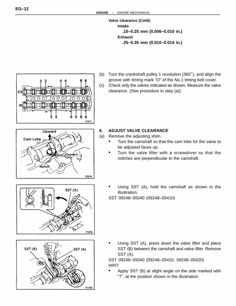
(b) Turn the crankshaft pulley 1 revolution (360°), and align thegroove with timing mark ”O” of the No.1 timing belt cover.
(c) Check only the valves indicated as shown. Measure the valveclearance. (See procedure in step (a))
6. ADJUST VALVE CLEARANCE(a) Remove the adjusting shim.
• Turn the camshaft so that the cam lobe for the valve tobe adjusted faces up.
• Turn the valve lifter with a screwdriver so that thenotches are perpendicular to the camshaft.
• Using SST (A), hold the camshaft as shown in theillustration.
SST 09248–55040 (09248–05410)
• Using SST (A), press down the valve lifter and placeSST (B) between the camshaft and valve lifter. RemoveSST (A).
SST 09248–55040 (09248–05410, 09248–05420)HINT:• Apply SST (B) at slight angle on the side marked with
”7”, at the position shown in the illustration.
EG–12–ENGINE ENGINE MECHANICAL

• Insert SST (B) gently from the inside as shown in theillustration.
• Using a small screwdriver and a magnetic finger,remove the adjusting shim.
(b) Determine the replacement adjusting shim size according tothe following Formula or Charts on the next 2 pages:• Using a micrometer, measure the thickness of the
removed shim.• Calculate the thickness of a new shim so the valve
clearance comes within specified value.T ......... Thickness of used shimA ......... Measured valve clearanceN ......... Thickness of new shimIntake
N = T + (A–0.20 mm (0.008 in.))Exhaust
N = T + (A–0.30 mm (0.012 in.))
• Select a new shim with a thickness as close as possibleto the calculated values.
HINT: Shims are available in 17 sizes in increments of 0.050mm (0.0020 in.), from 2.500 mm (0.0984 in.) to 3.300 mm(0.1299 in.).
(c) Install a new adjusting shim.• Place a new adjusting shim on the valve lifter, with
imprinted numbers facing down.• Press down the valve lifter with SST (A), and remove
SST (B).SST 09248–55040
(d) Recheck the valve clearance.
–ENGINE ENGINE MECHANICALEG–13

EG–14–ENGINE ENGINE MECHANICAL

–ENGINE ENGINE MECHANICALEG–15
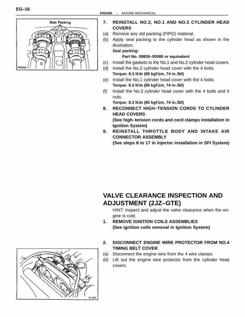
7. REINSTALL NO.2, NO.1 AND NO.3 CYLINDER HEADCOVERS
(a) Remove any old packing (FIPG) material.(b) Apply seal packing to the cylinder head as shown in the
illustration.Seal packing:
Part No. 08826–00080 or equivalent
(c) Install the gaskets to the No.1 and No.2 cylinder head covers.(d) Install the No.2 cylinder head cover with the 4 bolts.
Torque: 8.3 N ⋅m (85 kgf ⋅cm, 74 in. ⋅lbf)
(e) Install the No.1 cylinder head cover with the 4 bolts.Torque: 8.3 N ⋅m (85 kgf ⋅cm, 74 in. ⋅lbf)
(f) Install the No.3 cylinder head cover with the 4 bolts and 4nuts.Torque: 8.3 N ⋅m (85 kgf ⋅cm, 74 in. ⋅lbf)
8. RECONNECT HIGH–TENSION CORDS TO CYLINDERHEAD COVERS(See high–tension cords and cord clamps installation inIgnition System)
9. REINSTALL THROTTLE BODY AND INTAKE AIRCONNECTOR ASSEMBLY(See steps 8 to 17 in injector installation in SFI System)
VALVE CLEARANCE INSPECTION ANDADJUSTMENT (2JZ–GTE)
HINT: Inspect and adjust the valve clearance when the en-gine is cold.
1. REMOVE IGNITION COILS ASSEMBLIES(See ignition coils removal in Ignition System)
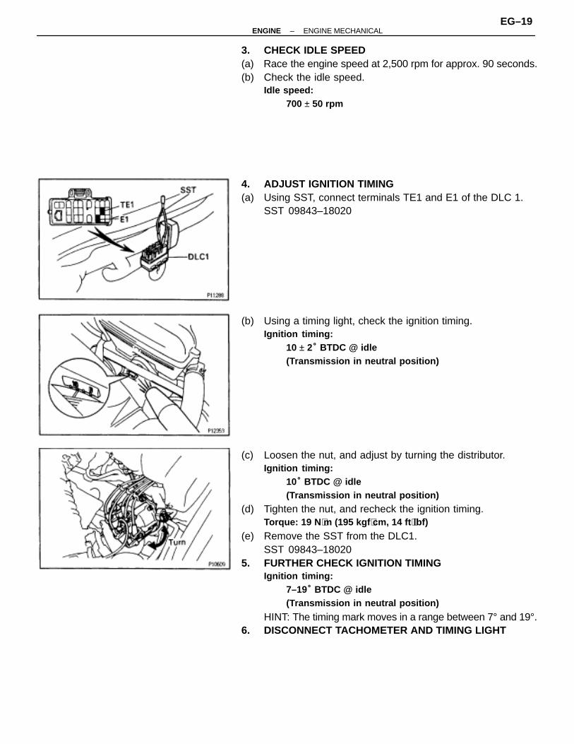
2. DISCONNECT ENGINE WIRE PROTECTOR FROM NO.4TIMING BELT COVER
(a) Disconnect the engine wire from the 4 wire clamps.(b) Lift out the engine wire protector from the cylinder head
covers.
EG–16–ENGINE ENGINE MECHANICAL

3. DISCONNECT ENGINE WIRE PROTECTOR FROM COWLTOP PANEL
(a) Remove the bolt, and disconnect the ground strap.(b) Remove the 2 bolts, and lift up the engine wire protector.
4. REMOVE IAC VALVE PIPE(a) Disconnect the 5 air hoses from the IAC valve pipe.(b) Remove the IAC valve pipe from the pipe clamp on the No.1
cylinder head cover.
5. REMOVE NO.1 AND NO.2 CYLINDER HEAD COVERS(a) Disconnect the cruise control actuator cable from the cable
bracket.(b) Remove the bolt holding the VSV to the turbo outlet duct.(c) Disconnect the 2 PCV hoses from the cylinder head covers.
(d) Remove the 6 bolts, 2 nuts, 8 seal washers, No.1 cylinderhead cover and gasket.
(e) Remove the 6 bolts, 2 nuts, 8 seal washers, No.2 cylinderhead cover and gasket.
6. SET NO.1 CYLINDER TO TDC/COMPRESSION(See step 4 in valve clearance inspection and adjustment(2JZ–GE))
7. INSPECT VALVE CLEARANCE(See step 5 in valve clearance inspection and adjustment(2JZ–GE))
8. ADJUST VALVE CLEARANCE(See step 6 in valve clearance inspection and adjustment(2JZ–GE))
–ENGINE ENGINE MECHANICALEG–17

9. REINSTALL NO.1 AND NO.2 CYLINDER HEAD COVERS(a) Remove any old packing (FIPG) material.(b) Apply seal packing to the cylinder head as shown in the
illustration.Seal packing:
Part No. 08826–00080 or equivalent
(c) Install the gaskets to the No.1 and No.2 cylinder head covers.(d) Install the 12 seal washers to the bolts.(e) Install the No.2 cylinder head cover with the 6 bolts, 4 seal
washers and 4 nuts.Torque: 5.4 N ⋅m (55 kgf ⋅cm, 48 in. ⋅lbf)
(f) Install the No.1 cylinder head cover with the 6 bolts, 4 sealwashers and 4 nuts.Torque: 5.4 N ⋅m (55 kgf ⋅cm, 48 in. ⋅lbf)
(g) Connect the 2 PCV hoses to the cylinder head covers.(h) Install the bolt holding the VSV to the turbo outlet duct.(i) Connect the cruise control actuator cable to the cable
bracket.10. RECONNECT ENGINE WIRE PROTECTOR TO NO.4
TIMING BELT COVER11. REINSTALL IAC VALVE PIPE12. RECONNECT ENGINE WIRE PROTECTOR TO COWL
TOP PANEL13. REINSTALL IGNITION COILS ASSEMBLIES
(See ignition coils installation in Ignition System)
IGNITION TIMING INSPECTION ANDADJUSTMENT(2JZ–GE)1. WARM UP ENGINE
Allow the engine to warm up to normal operating tempera-ture.
2. CONNECT TACHOMETER AND TIMING LIGHTConnect the tester probe of a tachometer to terminal IG � ofthe DLC1.NOTICE:• Never allow the tachometer terminal to touch ground as it
could result in damage to the Igniter and/or ignition coil.• As some tachometers are not compatible with this ignition
system, we recommend that you confirm the compatibilityof your unit before use.
EG–18–ENGINE ENGINE MECHANICAL
3. CHECK IDLE SPEED(a) Race the engine speed at 2,500 rpm for approx. 90 seconds.(b) Check the idle speed.
Idle speed:700 ± 50 rpm
4. ADJUST IGNITION TIMING(a) Using SST, connect terminals TE1 and E1 of the DLC 1.
SST 09843–18020
(b) Using a timing light, check the ignition timing.Ignition timing:
10 ± 2° BTDC @ idle(Transmission in neutral position)
(c) Loosen the nut, and adjust by turning the distributor.Ignition timing:
10° BTDC @ idle(Transmission in neutral position)
(d) Tighten the nut, and recheck the ignition timing.Torque: 19 N ⋅m (195 kgf ⋅cm, 14 ft ⋅lbf)
(e) Remove the SST from the DLC1.SST 09843–18020
5. FURTHER CHECK IGNITION TIMINGIgnition timing:
7–19° BTDC @ idle(Transmission in neutral position)
HINT: The timing mark moves in a range between 7° and 19°.6. DISCONNECT TACHOMETER AND TIMING LIGHT
–ENGINE ENGINE MECHANICALEG–19
IGNITION TIMING INSPECTION(2JZ–GTE)1. WARM UP ENGINE
Allow the engine to warm up to normal operating tempera-ture.
2. CONNECT TACHOMETER AND TIMING LIGHT(See step 2 in ignition timing inspection and adjustment(2JZ–GE))
3. CHECK IDLE SPEED(a) Race the engine speed at 2,500 rpm for approx. 90 seconds.(b) Check the idle speed.
Idle speed:650 ± 50 rpm
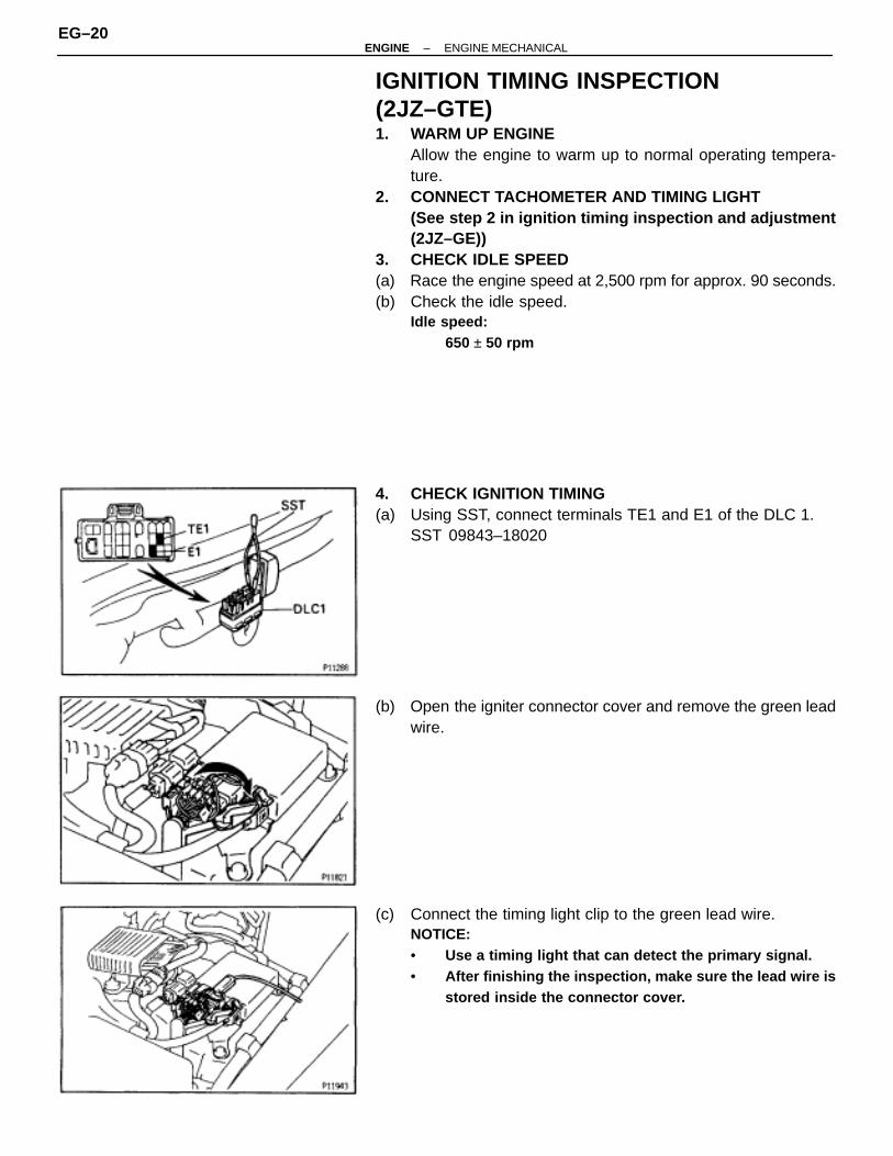
4. CHECK IGNITION TIMING(a) Using SST, connect terminals TE1 and E1 of the DLC 1.
SST 09843–18020
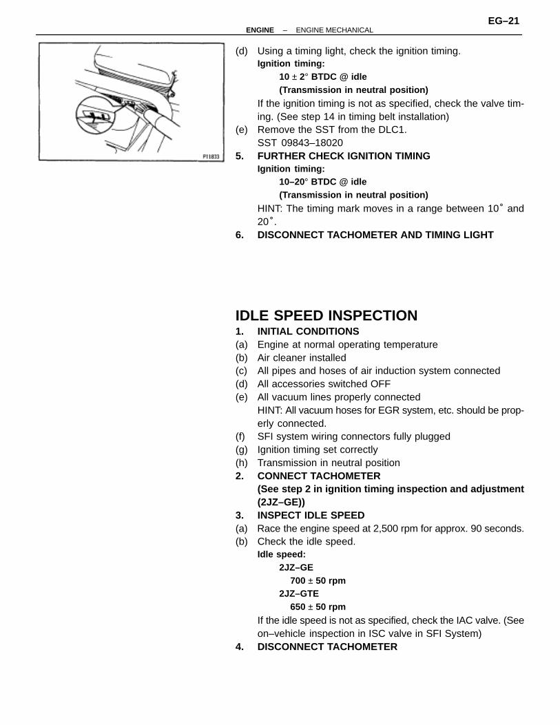
(b) Open the igniter connector cover and remove the green leadwire.
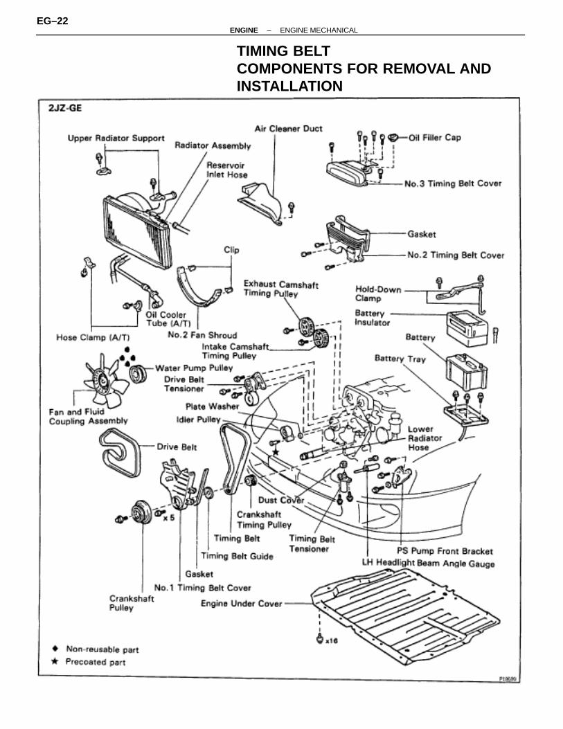
(c) Connect the timing light clip to the green lead wire.NOTICE:• Use a timing light that can detect the primary signal.• After finishing the inspection, make sure the lead wire is
stored inside the connector cover.
EG–20–ENGINE ENGINE MECHANICAL
(d) Using a timing light, check the ignition timing.Ignition timing:
10 ± 2° BTDC @ idle(Transmission in neutral position)
If the ignition timing is not as specified, check the valve tim-ing. (See step 14 in timing belt installation)
(e) Remove the SST from the DLC1.SST 09843–18020
5. FURTHER CHECK IGNITION TIMINGIgnition timing:
10–20° BTDC @ idle(Transmission in neutral position)
HINT: The timing mark moves in a range between 10° and20°.
6. DISCONNECT TACHOMETER AND TIMING LIGHT
IDLE SPEED INSPECTION1. INITIAL CONDITIONS(a) Engine at normal operating temperature(b) Air cleaner installed(c) All pipes and hoses of air induction system connected(d) All accessories switched OFF(e) All vacuum lines properly connected
HINT: All vacuum hoses for EGR system, etc. should be prop-erly connected.
(f) SFI system wiring connectors fully plugged(g) Ignition timing set correctly(h) Transmission in neutral position2. CONNECT TACHOMETER
(See step 2 in ignition timing inspection and adjustment(2JZ–GE))
3. INSPECT IDLE SPEED(a) Race the engine speed at 2,500 rpm for approx. 90 seconds.(b) Check the idle speed.
Idle speed:2JZ–GE
700 ± 50 rpm2JZ–GTE
650 ± 50 rpm
If the idle speed is not as specified, check the IAC valve. (Seeon–vehicle inspection in ISC valve in SFI System)
4. DISCONNECT TACHOMETER
–ENGINE ENGINE MECHANICALEG–21
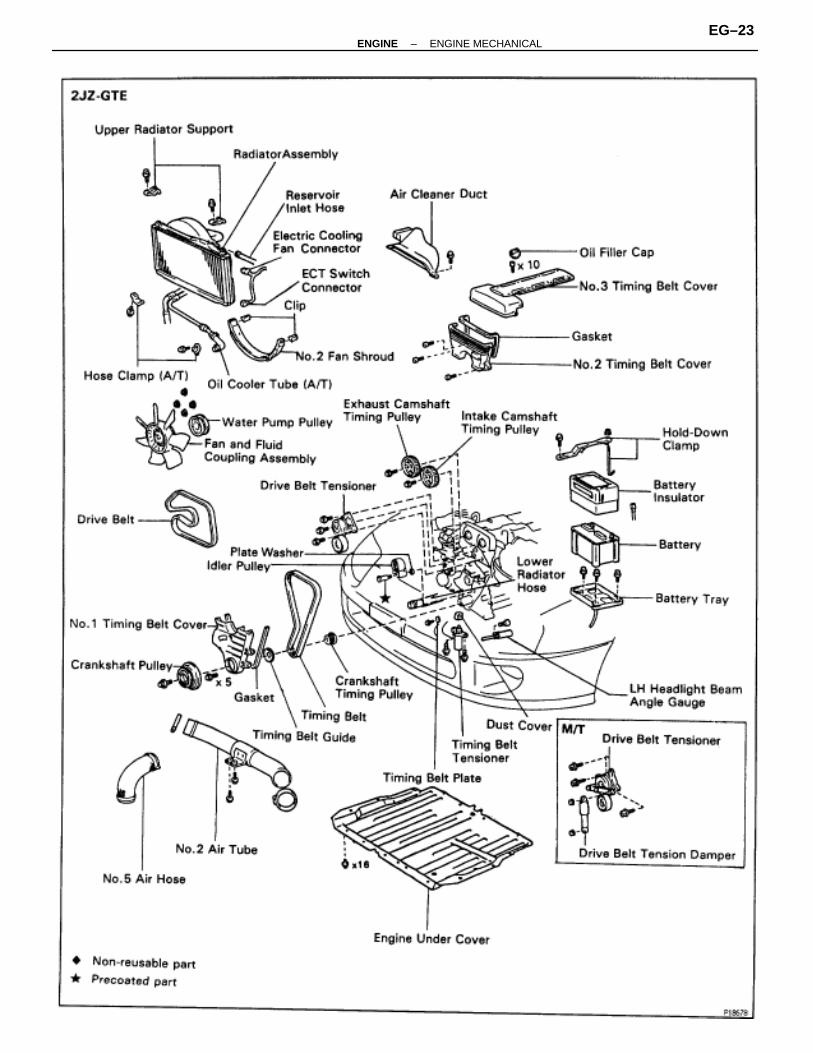
TIMING BELTCOMPONENTS FOR REMOVAL ANDINSTALLATION
EG–22–ENGINE ENGINE MECHANICAL
–ENGINE ENGINE MECHANICALEG–23

TIMING BELT REMOVAL1. REMOVE RADIATOR ASSEMBLY
(See radiator removal in Cooling System)2. 2JZ–GTE M/T:
REMOVE DRIVE BELT TENSIONER DAMPERRemove the 2 nuts and tensioner damper.
3. REMOVE DRIVE BELT, FAN, FLUID COUPLINGASSEMBLY AND WATER PUMP PULLEY(See step 6 in water pump removal in Cooling System)
4. REMOVE NO.3 TIMING BELT COVER(a) Remove the oil filler cap.(b) 2JZ–GE:
Using a 5 mm hexagon wrench, remove the 6 bolts and beltcover.
(c) 2JZ–GTE:Using a 5 mm hexagon wrench, remove the 10 bolts and beltcover.
5. REMOVE NO.2 TIMING BELT COVERUsing a 5 mm hexagon wrench, remove the 3 bolts, belt coverand gasket.If you are unable to loosen the bolt on the right because thePS pump pulley interferes with the hexagon wrench, first re-move the pulley.
6. REMOVE DRIVE BELT TENSIONERRemove the 3 bolts and tensioner.
EG–24–ENGINE ENGINE MECHANICAL

7. SET NO.1 CYLINDER TO TDC/COMPRESSION(a) Turn the crankshaft pulley, and align its groove with timing
mark ”O” of the No.1 timing belt cover.NOTICE: Always turn the crankshaft clockwise.
(b) Check that the timing marks of the camshaft timing pulleysare aligned with the timing marks of the No.4 timing beltcover.If not, turn the crankshaft 1 revolution (360°).
8. REMOVE TIMING BELT FROM CAMSHAFT TIMINGPULLEYSHINT (Re–using timing belt): Place matchmarks on the timingbelt and camshaft timing pulleys as shown in the illustration.
(a) Alternately loosen the 2 bolts, and remove them, thetensioner and dust boot.
(b) Disconnect the timing belt from the camshaft timing pulleys.
–ENGINE ENGINE MECHANICALEG–25

9. REMOVE CAMSHAFT TIMING PULLEYSUsing SST, remove the pulley bolt. Remove the 2 timing pul-leys.SST 09960–10010 (09962–01000, 09963–01000)
10. A/T:DISCONNECT OIL COOLER TUBESRemove the 2 bolts and hose clamps, and disconnect oilcooler tubes.
11. REMOVE CRANKSHAFT PULLEY(a) Using SST, loosen the pulley bolt.
SST 09213–70010, 09330–00021(b) Remove the pulley bolt.
(c) Using SST, remove the pulley.SST 09950–50010 (09954–05030, 09551–05010,
09552–05010, 09553–05020)
12. 2JZ–GE:REMOVE PS PUMP FRONT BRACKETRemove the 3 bolts, plate washer and pump front bracket.
EG–26–ENGINE ENGINE MECHANICAL
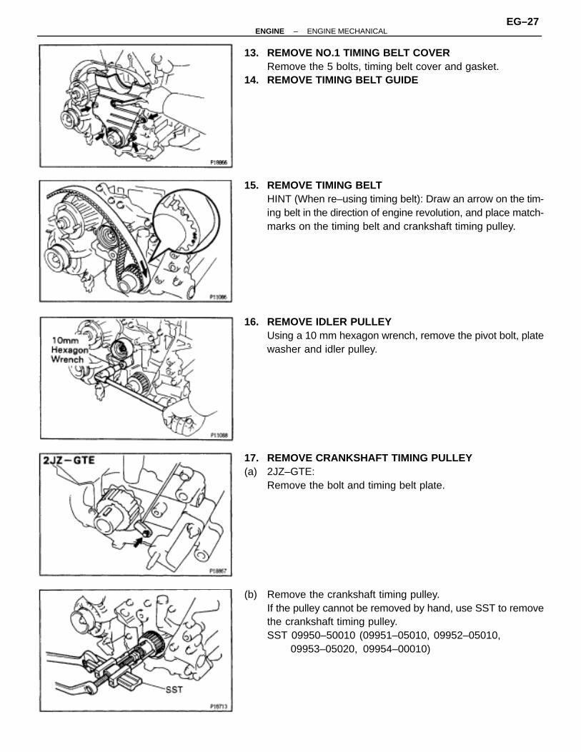
13. REMOVE NO.1 TIMING BELT COVERRemove the 5 bolts, timing belt cover and gasket.
14. REMOVE TIMING BELT GUIDE
15. REMOVE TIMING BELTHINT (When re–using timing belt): Draw an arrow on the tim-ing belt in the direction of engine revolution, and place match-marks on the timing belt and crankshaft timing pulley.
16. REMOVE IDLER PULLEYUsing a 10 mm hexagon wrench, remove the pivot bolt, platewasher and idler pulley.
17. REMOVE CRANKSHAFT TIMING PULLEY(a) 2JZ–GTE:
Remove the bolt and timing belt plate.
(b) Remove the crankshaft timing pulley.If the pulley cannot be removed by hand, use SST to removethe crankshaft timing pulley.SST 09950–50010 (09951–05010, 09952–05010,
09953–05020, 09954–00010)
–ENGINE ENGINE MECHANICALEG–27

TIMING BELT COMPONENTSINSPECTION1. INSPECTION TIMING BELT
NOTICE:• Do not bend, twist or turn the timing belt inside out.• Do not allow the timing belt to come into contact with oil,
water or steam.• Do not utilize timing belt tension when installing or re-
moving the mount bolt of the camshaft timing pulley.
If there are any defects, as shown in the illustrations, checkthe following points.
(a) Premature parting• Check for proper installation.• Check the timing cover gasket for damage and proper
installation.(b) If the belt teeth are cracked or damaged, check to see if either
camshaft is locked.(c) If there is noticeable wear or cracks on the belt face, check
to see if there are nicks on the side of the idler pulley lock.(d) If there is wear or damage on only one side of the belt, check
the belt guide and the alignment of each pulley.(e) If there is noticeable wear on the belt teeth, check timing
cover for damage and check gasket has been installedcorrectly and for foreign material on the pulley teeth.If necessary, replace the timing belt.
2. INSPECT IDLER PULLEYCheck the turning smoothness of the idler pulley.If necessary, replace the idler pulley.
3. INSPECT DRIVE BELT TENSIONERCheck the turning smoothness of the tensioner.If necessary, replace the tensioner.
4. INSPECT TIMING BELT TENSIONER(a) Visually check tensioner for oil leakage.
HINT: If there is only the faintest trace of oil on the seal on thepush rod side, the tensioner is all right.If leakage is found, replace tensioner.
EG–28–ENGINE ENGINE MECHANICAL

(b) Hold the tensioner with both hands and push the push rodstrongly against the floor or wall to check that it doesn’t move.If the push rod moves, replace the tensioner.
(c) Measure the protrusion of the push rod from the housing end.Protrusion:
8.0–8.8 mm (0.315–0.346 in.)
If the protrusion is not as specified, replace the tensioner.
5. 2JZ–GTE M/T:INSPECT DRIVE BELT TENSION DAMPERCompress and extend the tension damper rod and check thatthere is no abnormal resistance or unusual operationsounds.If there is any abnormality, replace the tension damper witha new one.
NOTICE: When discarding the tension damper, use the follow-ing procedure.
• Fully extend the damper rod.• Using a drill, make a hole in the cylinder as shown to
release the gas inside.CAUTION: The gas coming out is harmless, but be careful ofthe chips which may fly up when drilling.
TIMING BELT INSTALLATION1. INSTALL CRANKSHAFT TIMING PULLEY(a) Align the pulley set key with the key groove of the pulley.(b) Slide on the timing pulley facing the flange side inward.
–ENGINE ENGINE MECHANICALEG–29

(c) 2JZ–GTE:Install the timing belt plate with the bolt.Torque: 7.8 N ⋅m (80 kgf ⋅cm, 69 in. ⋅lbf)
2. INSTALL IDLER PULLEY(a) Apply adhesive to 2 or 3 threads of the pivot bolt.
Adhesive:Part No. 08833–00080, THREE BOND 1344, LOCTITE242 or equivalent
(b) Using a 10 mm hexagon wrench, install the plate washer andpulley with the pivot bolt.Torque: 34 N ⋅m (350 kgf ⋅cm, 25 ft ⋅lbf)
(c) Check that the pulley bracket moves smoothly.
3. TEMPORARILY INSTALL TIMING BELTNOTICE: The engine should be cold.
(a) Using the crankshaft pulley bolt, turn the crankshaft, andalign the timing marks on the crankshaft timing pulley and onthe oil pump body.
(b) Remove any oil or water on the crankshaft timing pulley andidler pulley, and keep them clean.
(c) Install the timing belt on the crankshaft timing pulley and idlerpulley.HINT (When re–using timing belt): Align the match marks ofthe crankshaft timing pulley and timing belt, and install thebelt with the arrow pointing in the direction of engine revolu-tion.
4. INSTALL TIMING BELT GUIDEInstall the guide, facing the cup side outward.
5. INSTALL NO.1 TIMING BELT COVER
EG–30–ENGINE ENGINE MECHANICAL

6. 2JZ–GE:INSTALL PS PUMP FRONT BRACKET
(a) Install the pump front bracket with the 2 bolts (A).Torque: 58 N ⋅m (590 kgf ⋅cm, 43 ft ⋅lbf)
(b) Install the plate washer and bolt (b) to the oil pump.Torque: 52 N ⋅m (530 kgf ⋅cm, 38 ft ⋅lbf)
7. INSTALL CRANKSHAFT PULLEY(a) Align the pulley set key with the key groove of the pulley, and
slide on the pulley.(b) Using SST, install the bolt.
SST 09213–70010, 09330–00021Torque: 324 N ⋅m (3,300 kgf ⋅cm, 239 ft ⋅lbf)
8. A/T:CONNECT OIL COOLER TUBES
9. INSTALL CAMSHAFT TIMING PULLEYS(a) Align the camshaft knock pin with the groove of the pulley,
and slide on the timing pulley.(b) Temporarily install the timing pulley bolt.
(c) Using SST, tighten the pulley bolt.SST 09960–10010 (09962–01000, 09963–01000)Torque: 79 N ⋅m (810 kgf ⋅cm, 59 ft ⋅lbf)
10. SET NO.1 CYLINDER TO TDC/COMPRESSION(a) Turn the crankshaft pulley, and align its groove with timing
mark ”O” of the No.1 timing belt cover.NOTICE: Always turn the crankshaft clockwise.
–ENGINE ENGINE MECHANICALEG–31

(b) Using SST, align the timing marks of the camshaft timingpulleys and No.4 timing belt cover.SST 09960–10010 (09962–01000, 09963–01000)
11. INSTALL TIMING BELTHINT (When re–using timing belt): Align the matchmarks ofthe timing belt and camshaft timing pulleys.
(a) Remove any oil or water on the camshaft timing pulley, andkeep it clean.
(b) Install the timing belt, checking the tension between thecrankshaft timing pulley and exhaust camshaft timing pulley.
12. SET TIMING BELT TENSIONER(a) Using a press, slowly press in the push rod using 981 –9,807
N (100–1,000 kgf, 220–2,205 lbf) of force.(b) Align the holes of the push rod and housing, pass a 1.5 mm
hexagon wrench through the holes to keep the push rodretracted.
(c) Release the press.
(d) Install the dust boot onto the tensioner.
13. INSTALL TIMING BELT TENSIONER(a) Temporarily install the tensioner with the 2 bolts.(b) Alternately tighten the 2 bolts.
Torque: 26 N ⋅m (270 kgf ⋅cm, 20 ft ⋅lbf)
EG–32–ENGINE ENGINE MECHANICAL

(c) Remove the 1.5 mm hexagon wrench from the tensioner.
14. CHECK VALVE TIMING(a) Slowly turn the crankshaft pulley 2 revolutions from TDC to
TDC.NOTICE: Always turn the crankshaft clockwise.
(b) Check that each pulley aligns with the timing marks as shownin the illustration.If the marks do not align, remove the timing belt and reinstallit.
15. INSTALL DRIVE BELT TENSIONERInstall the tensioner with the 3 bolts.Torque: 21 N ⋅m (210 kgf ⋅cm, 15 ft ⋅lbf)NOTICE: Be careful not to drop the bolts inside the timing beltcover.
16. INSTALL NO.2 TIMING BELT COVER17. INSTALL NO.3 TIMING BELT COVER18. INSTALL WATER PUMP PULLEY, FAN, FLUID COUPLING
ASSEMBLY AND DRIVE BELT(See step 10 in water pump installation in Cooling Sys-tem)
19. 2JZ–GTE M/T:INSTALL DRIVE BELT TENSIONER DAMPERTorque: 20 N ⋅m (200 kgf ⋅cm, 14 ft ⋅lbf)
20. INSTALL RADIATOR ASSEMBLY(See radiator installation in Cooling System)
21. ROAD TEST VEHICLECheck for abnormal noise, shock, slippage, correct shiftpoints and smooth operation.
–ENGINE ENGINE MECHANICALEG–33

CYLINDER HEADCOMPONENTS FOR REMOVAL ANDINSTALLATION
EG–34–ENGINE ENGINE MECHANICAL

–ENGINE ENGINE MECHANICALEG–35

EG–36–ENGINE ENGINE MECHANICAL

–ENGINE ENGINE MECHANICALEG–37

EG–38–ENGINE ENGINE MECHANICAL
–ENGINE ENGINE MECHANICALEG–39

EG–40–ENGINE ENGINE MECHANICAL

CYLINDER HEAD REMOVAL (2JZ–GE)1. REMOVE ENGINE UNDER COVER2. DRAIN ENGINE COOLANT3. REMOVE AIR CLEANER DUCT4. REMOVE AIR CLEANER, VAF METER AND INTAKE AIR
CONNECTOR PIPE ASSEMBLY(See step 6 in engine removal in Engine Mechanical)
5. REMOVE DRIVE BELTLoosen the drive belt tension by turning the drive belt tension-er clockwise, and remove the drive belt.
6. REMOVE NO.2 FRONT EXHAUST PIPE(See step 22 in engine removal in Engine Mechanical)
7. REMOVE EXHAUST MANIFOLDS(a) Except California:
Remove the 4 nuts and manifold heat insulator.(b) Disconnect the 2 (main heated) oxygen sensor connectors.(c) Remove the 4 nuts, exhaust manifold and gasket.
Remove the No.1 and No.2 exhaust manifolds.
8. DISCONNECT PS PUMP WITHOUTDISCONNECTING HOSES
(a) Disconnect these hoses:(1) Air hose from No.4 timing belt cover(2) Air hose from air intake chamber
(b) Remove the 2 bolts, and disconnect the pump housing fromthe pump bracket.HINT: Put aside the pump housing, and suspend it.
(c) Remove the 2 bolts and pump rear stay.
9. DISCONNECT BRAKE BOOSTER VACUUM HOSE10. DISCONNECT EVAP HOSE11. REMOVE THROTTLE BODY AND INTAKE AIR
CONNECTOR ASSEMBLY(See injector removal in SFI System)
–ENGINE ENGINE MECHANICALEG–41

12. REMOVE AIR INTAKE CHAMBER STAYS(a) Remove the bolt, nut and No.1 stay.(b) Remove the bolt, nut and No.2 stay.13. REMOVE NO.2 VACUUM PIPE AND VSV ASSEMBLY
14. REMOVE NO.3 TIMING BELT COVER(a) Remove the oil filler cap.(b) Using a 5 mm hexagon wrench, remove the 6 bolts and timing
belt cover.15. REMOVE CYLINDER HEAD REAR COVER
Using a 5 mm hexagon wrench, remove the 4 bolts and cylin-der head rear cover.
16. DISCONNECT HIGH–TENSION CORDS FROMCYLINDER HEAD COVERS(See step 4 in high–tension cords and cord clamps re-moval in Ignition System)
17. REMOVE DISTRIBUTOR AND CORDS ASSEMBLY(See steps 1 to 3 in distributor removal in Ignition Sys-tem)
18. REMOVE SPARK PLUGS19. REMOVE TIMING BELT FROM CAMSHAFT TIMING
PULLEYS(See steps 5 to 8 in timing belt removal)NOTICE:• Support the timing belt, so that the meshing of the crank-
shaft timing pulley and timing belt does not shift.• Be careful not to drop anything inside the timing belt cov-
er.• Do not allow the timing belt to come into contact with oil,
water or dust.
20. REMOVE WATER BYPASS OUTLET AND NO.1 WATERBYPASS PIPE(See step 13 in water pump removal in Cooling System)
21. DISCONNECT FUEL RETURN HOSE(a) Disconnect the fuel return hose from the fuel return pipe. Plug
the hose end.(b) Disconnect the fuel return hose from the oil dipstick guide.22. REMOVE ENGINE WIRE BRACET
Remove the bolt and bracket, disconnect the engine wire theintake manifold stay.
EG–42–ENGINE ENGINE MECHANICAL

23. REMOVE OIL DIPSTICK GUIDES FOR ENGINE ANDTRANSMISSION
(a) Remove the 2 bolts.(b) Pull out the dipstick guide together with the dipstick.(c) Remove the O–ring from the dipstick guide.24. REMOVE STARTER
(See starter removal in Starting System)
25. REMOVE AIR INTAKE CHAMBER(a) Except California:
Disconnect the vacuum sensing hose from the fuel pressureregulator.
(b) Remove the bolt holding the engine wire protector to the theair intake chamber.
(c) Remove the 5 bolts, nut, air intake chamber and gasket.
26. REMOVE VACUUM CONTROL VALVE SET(a) Disconnect the VSV connector.(b) Remove the 2 nuts and vacuum control valve set.
27. DISCONNECT ENGINE WIRE(a) Remove the bolt, and disconnect the engine wire bracket
from the water pump.
(b) Remove the 2 bolts, and disconnect the 2 ground straps fromthe intake manifold.
(c) Remove the 2 bolts, and disconnect the 2 wire clamps fromthe intake manifold.
(d) Disconnect these connectors:• 6 injector connectors• ECT sensor connector• ECT sender gauge connector
–ENGINE ENGINE MECHANICALEG–43

(e) Remove the 3 nuts, and disconnect the engine wire protectorfrom the intake manifold.
28. REMOVE WATER OUTLET AND NO.1 BYPASS HOSEASSEMBLYRemove the 2 nuts, bolt and water outlet.
29. REMOVE INTAKE MANIFOLD STAYRemove the 2 bolts and manifold stay.
30. REMOVE FUEL PRESSURE PULSATION DAMPER(See step 2 in fuel pressure pulsation damper in SFI Sys-tem)
31. REMOVE FUEL INLET PIPE(a) Remove the clamp bolt from the intake manifold.(b) Remove the union bolt and 2 gaskets, and disconnect the
fuel inlet pipe.
32. REMOVE INTAKE MANIFOLD AND DELIVERY PIPEASSEMBLYRemove the 6 bolts, 2 nuts, the intake manifold, delivery pipeassembly and gasket.
EG–44–ENGINE ENGINE MECHANICAL
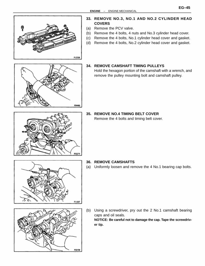
33. REMOVE NO.3, NO.1 AND NO.2 CYLINDER HEADCOVERS
(a) Remove the PCV valve.(b) Remove the 4 bolts, 4 nuts and No.3 cylinder head cover.(c) Remove the 4 bolts, No.1 cylinder head cover and gasket.(d) Remove the 4 bolts, No.2 cylinder head cover and gasket.
34. REMOVE CAMSHAFT TIMING PULLEYSHold the hexagon portion of the camshaft with a wrench, andremove the pulley mounting bolt and camshaft pulley.
35. REMOVE NO.4 TIMING BELT COVERRemove the 4 bolts and timing belt cover.
36. REMOVE CAMSHAFTS(a) Uniformly loosen and remove the 4 No.1 bearing cap bolts.
(b) Using a screwdriver, pry out the 2 No.1 camshaft bearingcaps and oil seals.NOTICE: Be careful not to damage the cap. T ape the screwdriv-er tip.
–ENGINE ENGINE MECHANICALEG–45

(c) Uniformly loosen and remove the 12 bearing cap bolts, inseveral passes, in the sequence shown, and remove the 6bearing caps and camshaft.
(d) Remove the intake and exhaust camshafts.
37. REMOVE CYLINDER HEAD(a) Using a 10 mm bi–hexagon wrench, uniformly loosen and
remove the 14 cylinder head bolts, in several passes, in thesequence shown.NOTICE: Cylinder head warpage or cracking could result fromremoving in incorrect order.
(b) Remove the 14 plate washers.
(c) Lift the cylinder head from the dowels on the cylinder block.(d) Place the head on wooden blocks on a bench.
If the cylinder head is difficult to lift off, pry with a screwdriverbetween the cylinder head and block projection.NOTICE: Be careful not to damage the contact surfaces of thecylinder head and cylinder block.
CYLINDER HEAD REMOVAL (2JZ–GTE)1. REMOVE TURBOCHARGER
(See turbocharger removal in Turbocharger System)2. REMOVE EXHAUST MANIFOLD
Remove the 12 nuts, exhaust manifold and 2 gaskets.3. M/T:
REMOVE DRIVE BELT TENSIONER DAMPER(See step 2 in timing belt removal)
EG–46–ENGINE ENGINE MECHANICAL

4. REMOVE DRIVE BELTLoosen the drive belt tension by turning the drive belt tension-er clockwise, and remove the drive belt.
5. REMOVE WATER OUTLET AND NO.1 WATER BYPASSPIPE
(a) Disconnect the upper radiator hose from the water outlet.(b) Disconnect the ECT sensor and sender gauge connectors.(c) Remove the 2 bolts, water outlet and gasket.
(d) Remove the No.1 water bypass pipe and 2 O–rings.
6. DISCONNECT PS PUMP WITHOUT DISCONNECTINGHOSES
(a) Disconnect these hoses:(1) Air hose from throttle body(2) Air hose from air intake chamber
(b) Remove the 2 bolts, and disconnect the pump housing fromthe pump bracket.HINT: Put aside the pump housing, and suspend it securely.
7. DISCONNECT FUEL RETURN HOSEDisconnect the fuel return hose from the fuel return pipe. Plugthe hose end.
8. REMOVE AIR INTAKE CHAMBER ASSEMBLY(See injector removal in SFI System)
–ENGINE ENGINE MECHANICALEG–47

9. DISCONNECT ENGINE WIRE(a) Disconnect these connectors and clamps:
(1) 6 injectors connectors(2) 2 camshaft position sensor connectors(3) 3 engine wire clamps from injector holders
(4) VSV connector for EVAP(b) Remove the 2 bolts, and disconnect the 2 ground straps from
the intake manifold.(c) Remove the nut, and disconnect the engine wire protector
from the intake manifold.10. REMOVE STARTER
(See starter removal in Starting System)
11. REMOVE PRESSURE TANK AND VSV ASSEMBLY(a) Disconnect the 2 vacuum hoses from the pressure tank.(b) Remove the 2 nuts and pressure tank and VSV assembly.12. REMOVE FUEL PRESSURE PULSATION DAMPER
(See step 2 in fuel pressure pulsation damper in SFI Sys-tem)
13. REMOVE FUEL INLET PIPERemove the union bolt, 2 gaskets, clamp bolt and fuel inletpipe.
14. REMOVE INTAKE MANIFOLD AND DELIVERY PIPEASSEMBLYRemove the 4 bolts, 2 nuts, engine wire bracket, the intakemanifold, delivery pipe assembly and gasket.
EG–48–ENGINE ENGINE MECHANICAL

15. REMOVE TIMING BELT FROM CAMSHAFT TIMINGPULLEYS(See steps 5 to 8 in timing belt removal)NOTICE:• Support the timing belt, so that the meshing of the crank-
shaft timing pulley and timing belt does not shift.• Be careful not to drop anything inside the timing belt cov-
er.• Do not allow the timing belt to come into contact with oil,
water or dust.
16. REMOVE IGNITION COILS ASSEMBLIES(See steps 2 to 5 in ignition coils removal in Ignition Sys-tem)
17. REMOVE SPARK PLUGS
18. REMOVE NO.1 AND NO.2 CYLINDER HEAD COVERS(a) Remove the 2 bolts, cruise control actuator cable bracket and
IAC valve pipe clamp.(b) Remove the PCV valve.(c) Remove the 6 bolts, 2 nuts, 8 seal washers and No.1 cylinder
head cover and gasket.(d) Remove the 6 bolts, 2 nuts, 8 seal washers and No.2 cylinder
head cover and gasket.19. REMOVE CAMSHAFT TIMING PULLEYS
(See step 34 cylinder head removal (2JZ–GE))20. REMOVE NO.4 TIMING BELT COVER
(See step 35 cylinder head removal (2JZ–GE))21. REMOVE CAMSHAFTS
(See step 36 cylinder head removal (2JZ–GE))22. REMOVE CYLINDER HEAD
(See step 37 cylinder head removal (2JZ–GE))
CYLINDER HEAD DISASSEMBLY1. 2JZ–GE:
REMOVE ENGINE HANGERS2. 2JZ–GE:
REMOVE ECT SENSOR AND SENDER GAUGE3. 2JZ–GE:
REMOVE THROTTLE CABLE BRACKET AND GROUNDSTRAP
–ENGINE ENGINE MECHANICALEG–49

4. 2JZ–GTE:REMOVE ENGINE HANGERS AND GROUND STRAP
5. 2JZ–GTE:REMOVE CAMSHAFT POSITION SENSORS
6. REMOVE EGR COOLER
7. REMOVE VALVE LIFTERS AND SHIMSHINT: Store the valve lifters and shims in correct order.
8. REMOVE VALVES(a) Using SST, compress the valve spring and remove the 2
keepers.SST 09202–70010
(b) Remove the spring retainer, valve spring, valve and springseat.HINT: Store the valves, valve springs, spring seats and springretainers in correct order.
(c) Using needle–nose pliers, remove the oil seal.
CYLINDER HEAD COMPONENTSINSPECTION AND REPAIR1. CLEAN TOP SURFACES OF PISTONS AND CYLINDER
BLOCK(a) Turn the crankshaft, and bring each piston to top dead center
(TDC). Using a gasket scraper, remove all the carbon fromthe piston top surface.
EG–50–ENGINE ENGINE MECHANICAL

(b) Using a gasket scraper, remove all the gasket material fromthe top surface of the cylinder block.
(c) Using compressed air, blow carbon and oil from the boltholes.CAUTION: Protect your eyes when using high pressure com-pressed air.
2. CLEAN CYLINDER HEADA. Remove gasket material
Using a gasket scraper, remove all the gasket material fromthe cylinder block surface.NOTICE: Be careful not to scratch the cylinder block contactsurface.
B. Clean combustion chambersUsing a wire brush, remove all the carbon from the combus-tion chambers.NOTICE: Be careful not to scratch the cylinder block contactsurface.
C. Clean valve guide bushingsUsing a valve guide bushing brush and solvent, clean all theguide bushings.
D. Clean cylinder headUsing a soft brush and solvent, thoroughly clean the cylinderhead.
–ENGINE ENGINE MECHANICALEG–51

3. INSPECT CYLINDER HEADA. Inspect for flatness
Using precision straight edge and feeler gauge, measure thesurfaces contacting the cylinder block, intake and exhaustmanifolds for warpage.Maximum warpage:
0.10 mm (0.0039 in.)
If warpage is greater than maximum, replace the cylinderhead.
B. Inspect for cracksUsing a dye penetrant, check the combustion chamber, in-take ports, exhaust ports and cylinder block surface forcracks.If cracked, replace the cylinder head.
4. CLEAN VALVES(a) Using a gasket scraper, chip off any carbon from the valve
head.(b) Using a wire brush, throughly clean the valve.
5. INSPECT VALVE STEMS AND GUIDE BUSHINGS(a) Using a caliper gauge, measure the inside diameter of the
guide bushing.Bushing inside diameter:
6.010–6.030 mm (0.2366–0.2374 in.)
EG–52–ENGINE ENGINE MECHANICAL

Bushing bore diametermm (in.)
10.985–11.006 mm(0.4325–0.4333 in.)
Both intake and exhaust
11.035–11.056 mm(0.4344–0.4353 in.)
Bushingsize
Use STD
Use O/S0.05
(b) Using a micrometer, measure the diameter of the valve stem.Valve stem diameter:
Intake5.970–5.985 mm (0.2350–0.2356 in.)
Exhaust5.965–5.980 mm (0.2348–0.2354 in.)
(c) Subtract the valve stem diameter measurement from theguide bushing inside diameter measurement.Standard oil clearance:
Intake.025–0.060 mm (0.0010–0.0024 in.)
Exhaust.030–0.065 mm (0.0012–0.0026 in.)
Maximum oil clearance:Intake
.08 mm (0.0031 in.)Exhaust
.10 mm (0.0039 in.)
If the clearance is greater than maximum, replace the valveand guide bushing.
6. IF NECESSARY, REPLACE VALVE GUIDE BUSHINGS(a) Using SST and a hammer, tap out the guide bushing.
SST 09201–10000 (09201–01060).09608–30022 (09608–05010)
(b) Using a caliper gauge, measure the bushing bore diameterof the cylinder head.
(c) Select a new guide bushing (STD or O/S 0.05).If the bushing bore diameter of the cylinder head is greaterthan 11.006 mm (0.4333 in.), machine the bushing bore tothe following dimension:
11.035–11.056 mm (0.4344–0.4353 in.)
If the bushing bore diameter of the cylinder head is greaterthan 11.056 mm (0.4353 in.), replace the cylinder head.
–ENGINE ENGINE MECHANICALEG–53

(d) Using SST and a hammer, tap in a new guide bushing to thespecified protrusion height.SST 09201–10000 (09201–01060), 09608–30022
(09608–05010)Protrusion height:
Intake12.3–12.7 mm (0.484–0.500 in.)
Exhaust11.4–11.8 mm (0.449–0.465 in.)
HINT: Different bushings are used for the intake and exhaust.
(e) Using a sharp 6 mm reamer, ream the guide bushing to obtainthe standard specified clearance (See step 6) between theguide bushing and valve stem.
7. INSPECT AND GRIND VALVES(a) Grind the valve enough to remove pits and carbon.(b) Check that the valve is ground to the correct valve face angle.
Valve face angle:44.5°
(c) Check the valve head margin thickness.Standard margin thickness:
0.8–1.2 mm (0.031–0.047 in.)Minimum margin thickness:
0.5 mm (0.020 in.)
If the margin thickness is less than minimum, replace thevalve.
EG–54–ENGINE ENGINE MECHANICAL
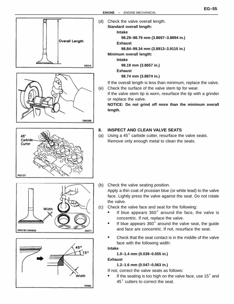
(d) Check the valve overall length.Standard overall length:
Intake98.29–98.79 mm (3.8697–3.8894 in.)
Exhaust98.84–99.34 mm (3.8913–3.9110 in.)
Minimum overall length:Intake
98.19 mm (3.8657 in.)Exhaust
98.74 mm (3.8874 in.)
If the overall length is less than minimum, replace the valve.(e) Check the surface of the valve stem tip for wear.
If the valve stem tip is worn, resurface the tip with a grinderor replace the valve.NOTICE: Do not grind off more than the minimum overalllength.
8. INSPECT AND CLEAN VALVE SEATS(a) Using a 45° carbide cutter, resurface the valve seats.
Remove only enough metal to clean the seats.
(b) Check the valve seating position.Apply a thin coat of prussian blue (or white lead) to the valveface. Lightly press the valve against the seat. Do not rotatethe valve.
(c) Check the valve face and seat for the following:• If blue appears 360° around the face, the valve is
concentric. If not, replace the valve.• If blue appears 360° around the valve seat, the guide
and face are concentric. If not, resurface the seat.
• Check that the seat contact is in the middle of the valveface with the following width:
Intake1.0–1.4 mm (0.039–0.055 in.)
Exhaust1.2–1.6 mm (0.047–0.063 in.)
If not, correct the valve seats as follows:• If the seating is too high on the valve face, use 15° and
45° cutters to correct the seat.
–ENGINE ENGINE MECHANICALEG–55

• If the seating is too low on the valve face, use 60° and45° cutters to correct the seat.
(d) Hand–lap the valve and valve seat with an abrasivecompound.
(e) After hand–lapping, clean the valve and valve seat.
9. INSPECT VALVE SPRINGS(a) Using a steel square, measure the deviation of the valve
spring.Maximum deviation:
2.0 mm (0.079 in.)
If deviation is greater than maximum, replace the valvespring.
(b) Using vernier calipers, measure the free length of the valvespring.Free length:
Blue painted mark41.74 mm (1.6433 in.)
Yellow painted mark41.70 mm (1.6417 in.)
If the free length is not as specified, replace the valve spring.
(c) Using a spring tester, measure the tension of the valve springat the specified installed length.Installed tension:
186–206 N (19.0–21.0 kgf, 42–46 lbf) at 34.5 mm(1.358 in.)
If the installed tension is not as specified, replace the valvespring.
EG–56–ENGINE ENGINE MECHANICAL

10. INSPECT CAMSHAFTS AND BEARINGSA. Inspect camshaft for runout(a) Place the camshaft on V–blocks.(b) Using a dial indicator, measure the circle runout at the center
journal.Maximum circle runout:
0.08 mm “(0.0031 in.)
If the circle runout is greater than maximum, replace the cam-shaft.
B. Inspect cam lobesUsing a micrometer, measure the cam lobe height.Standard cam lobe height:
Intake44.570–44.670 mm (1.7547–1.7587 in.)
Exhaust44.770–44.870 mm (1.7626–1.7665 in.)
Maximum cam lobe height:Intake
44.42 mm (1.7488 in.)Exhaust
44.62 mm (1.7567 in.)If the cam lobe height is less than minimum, replace the cam-shaft.
C. Inspect camshaft journalsUsing a micrometer, measure the journal diameter.Journal diameter:
28.949–28.965 mm (1.1397–1.1404 in.)
If the journal diameter is not as specified, check the oil clear-ance.
D. Inspect camshaft bearingsCheck the bearings for flaking and scoring.If the bearings are damaged, replace the bearing caps andcylinder head as a set.
E. Inspect camshaft journal oil clearance(a) Clean the bearing caps and camshaft journals.(b) Place the camshafts on the cylinder head.(c) Lay a strip of Plastigage across each of the camshaft
journals.
–ENGINE ENGINE MECHANICALEG–57

(d) Install the bearing caps.(See step 2 in cylinder head installation (2JZ–GE))Torque: 20 N ⋅m (200 kgf ⋅cm, 14 ft ⋅lbf)NOTICE: Do not turn the camshaft.
(e) Remove the bearing caps.
(f) Measure the Plastigage at its widest point.Standard oil clearance:
0.035–0.072 mm (0.0014–0.0028 in.)Maximum oil clearance:
0.10 mm (0.0039 in.)
If the oil clearance is greater than maximum, replace the cam-shaft. If necessary, replace the bearing caps and cylinderhead as a set.
(g) Completely remove the Plastigage.
F. Inspect camshaft thrust clearance(a) Install the camshafts.
(See step 2 in cylinder head installation (2JZ–GE))(b) Using a dial indicator, measure the thrust clearance while
moving the camshaft back and forth.Standard thrust clearance:
0.080–0.190 mm (0.0031–0.0075 in.)Maximum thrust clearance:
0.30 mm (0.0118 in.)
If the thrust clearance is greater than maximum, replace thecamshaft. If necessary, replace the bearing caps and cylin-der head as a set.
11. INSPECT VALVE LIFTERS AND LIFTER BORES(a) Using a caliper gauge, measure the lifter bore diameter of the
cylinder head.Lifter bore diameter:
31.000–31.016 mm (1.2205–1.2211 in.)
(b) Using a micrometer, measure the lifter diameter.
Lifter diameter:30.966–30.976 mm (1.2191–1.2195 in.)
(c) Subtract the lifter diameter measurement from the lifter borediameter measurement.Standard oil clearance:
0.024–0.050 mm (0.0009–0.0020 in.)Maximum oil clearance:
0.07 mm (0.0028 in.)
If the oil clearance is greater than maximum, replace the lifter.If necessary, replace the cylinder head.
EG–58–ENGINE ENGINE MECHANICAL

12. INSPECT AIR INTAKE CHAMBERUsing a precision straight edge and feeler gauge, measurethe surfaces contacting the intake manifold for warpage.Maximum warpage:
0.15 mm (0.0059 in.)
If warpage is greater than maximum, replace the chamber.
13. INSPECT INTAKE MANIFOLDUsing a precision straight edge and feeler gauge, measurethe surfaces contacting the cylinder head and air intakechamber for warpage.Maximum warpage:
0.15 mm (0.0059 in.)
If warpage is greater than maximum, replace the manifold.
14. 2JZ–GE:INSPECT EXHAUST MANIFOLDSUsing a precision straight edge and feeler gauge, measurethe surfaces contacting the cylinder head for warpage.Maximum warpage:
0.50 mm (0.0196 in.)
If warpage is greater than maximum, replace the manifold.
15. 2JZ–GTE:INSPECT EXHAUST MANIFOLDUsing a precision straight edge and feeler gauge, measurethe surfaces contacting the cylinder head for warpage.Maximum warpage:
0.80 mm (0.0315 in.)
If warpage is greater than maximum, replace the manifold.
–ENGINE ENGINE MECHANICALEG–59

16. INSPECT CYLINDER HEAD BOLTSUsing a vernier caliper, measure the thread outside diameterof the bolt.Standard outside diameter:
10.8–11.0 mm (0.425–0.433 in.)Minimum outside diameter:
10.7 mm (0.421 in.)
If the diameter is less than minimum, replace the bolt.
CYLINDER HEAD ASSEMBLYHINT:• Thoroughly clean all parts to be assembled.• Before installing the parts, apply new engine oil to all
sliding and rotating surfaces.• Replace all gaskets and oil seals with new ones.
1. INSTALL HEATER UNIONHINT: When using a new cylinder head, a new heater unionmust be installed.
(a) Apply adhesive to the end of the heater union as shown in theillustration.Adhesive:
Part No. 08833–00070, THREE BOND 1324 or equivalent
(b) Using a wooden block and hammer, tap in a new heaterunion, leaving standard position protruding from the cylinderhead.Standard protrusion:
2JZ–GE48 mm (1.89 in.)
2JZ–GTE73 mm (2.87 in.)
NOTICE: Do not tap it in too far.
2. INSTALL VALVES(a) Install a new oil seal on the valve guide bushing.
EG–60–ENGINE ENGINE MECHANICAL
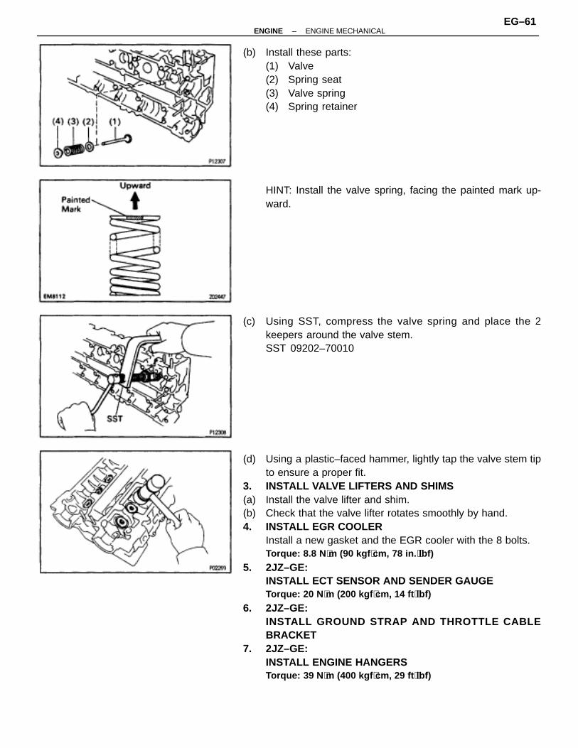
(b) Install these parts:(1) Valve(2) Spring seat(3) Valve spring(4) Spring retainer
HINT: Install the valve spring, facing the painted mark up-ward.
(c) Using SST, compress the valve spring and place the 2keepers around the valve stem.SST 09202–70010
(d) Using a plastic–faced hammer, lightly tap the valve stem tipto ensure a proper fit.
3. INSTALL VALVE LIFTERS AND SHIMS(a) Install the valve lifter and shim.(b) Check that the valve lifter rotates smoothly by hand.4. INSTALL EGR COOLER
Install a new gasket and the EGR cooler with the 8 bolts.Torque: 8.8 N ⋅m (90 kgf ⋅cm, 78 in. ⋅lbf)
5. 2JZ–GE:INSTALL ECT SENSOR AND SENDER GAUGETorque: 20 N ⋅m (200 kgf ⋅cm, 14 ft ⋅lbf)
6. 2JZ–GE:INSTALL GROUND STRAP AND THROTTLE CABLEBRACKET
7. 2JZ–GE:INSTALL ENGINE HANGERSTorque: 39 N ⋅m (400 kgf ⋅cm, 29 ft ⋅lbf)
–ENGINE ENGINE MECHANICALEG–61

8. 2JZ–GTE:INSTALL CAMSHAFT POSITION SENSORSInstall the gasket and sensor with the 2 bolts.Torque: 8.8 N ⋅m (90 kgf ⋅cm, 78 in. ⋅lbf)
9. 2JZ–GTE:INSTALL ENGINE HANGERS AND GROUND STRAPTorque: 39 N ⋅m (400 kgf ⋅cm, 29 ft ⋅lbf)
CYLINDER HEAD INSTALLATION(2JZ–GE)1. INSTALL CYLINDER HEADA. Place cylinder head on cylinder block(a) Place a new cylinder head gasket in position on the cylinder
block.NOTICE: Be sure to install it correctly.
(b) Place the cylinder head in position on the cylinder headgasket.
B. Install cylinder head boltsHINT:• The cylinder head bolts are tightened in 2 progressive
steps (steps (c) and (f)).• If any of bolts break or deform, replace them.
(a) Apply a light coat of engine oil on the threads and under theheads of the cylinder head bolts.
(b) Install the 14 plate washers to each cylinder head bolt.(c) Using a 10 mm bi–hexagon wrench, uniformly tighten the
cylinder head bolts, in several passes, in the sequenceshown.Torque: 34 N ⋅m (350 kgf ⋅cm, 25 ft ⋅lbf)
If any of the bolts do not meet the torque specification, re-place the bolt.
(d) Mark the front of the cylinder head bolt head with paint.
EG–62–ENGINE ENGINE MECHANICAL
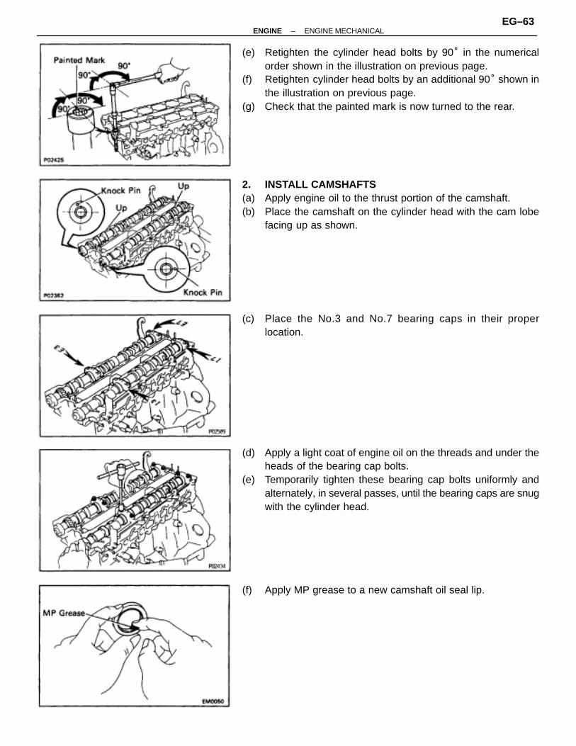
(e) Retighten the cylinder head bolts by 90° in the numericalorder shown in the illustration on previous page.
(f) Retighten cylinder head bolts by an additional 90° shown inthe illustration on previous page.
(g) Check that the painted mark is now turned to the rear.
2. INSTALL CAMSHAFTS(a) Apply engine oil to the thrust portion of the camshaft.(b) Place the camshaft on the cylinder head with the cam lobe
facing up as shown.
(c) Place the No.3 and No.7 bearing caps in their properlocation.
(d) Apply a light coat of engine oil on the threads and under theheads of the bearing cap bolts.
(e) Temporarily tighten these bearing cap bolts uniformly andalternately, in several passes, until the bearing caps are snugwith the cylinder head.
(f) Apply MP grease to a new camshaft oil seal lip.
–ENGINE ENGINE MECHANICALEG–63

(g) Install the 2 oil seals to the camshafts.
(h) Clean the installed surfaces of the No.1 bearing cap andcylinder head with cleaner.
(i) Apply seal packing to the No.1 bearing cap as shown.Seal packing:
Part No. 08826–00080 or equivalent
(j) Install the No.1, No.2, No.4, No.5 and No.6 bearing caps intheir proper locations.
(k) Apply a light coat of engine oil on the threads and under theheads of the bearing cap bolts.
(l) Install and uniformly tighten the 14 bearing cap bolts on oneside, in several passes, in the sequence shown.Torque: 20 N ⋅m (200 kgf ⋅cm, 14 ft ⋅lbf)
EG–64–ENGINE ENGINE MECHANICAL

(m) Using SST, push the 2 oil seals in as far as they can go.SST 09316–60010 (09316–00010, 09316–00050)
(n) Rotate the camshaft with a wrench at the hexagon position,bring the forward straight pin up.
(o) Loosen the 3 bearing cap bolts as shown, until they can beturned by hand; retighten, in several passes.Torque: 20 N ⋅m (200 kgf ⋅cm, 14 ft ⋅lbf)
(p) Turn the camshaft 1/3 of revolution.(q) Loosen the 2 bearing cap bolts as shown, until they can be
turned by hand; retighten, in several passes.Torque: 20 N ⋅m (200 kgf ⋅cm, 14 ft ⋅lbf)
(r) Turn the camshaft a further 1/3 of a revolution.(s) Loosen the 2 bearing cap bolts as shown, until they can be
turned by hand; retighten, in several passes.Torque: 20 N ⋅m (200 kgf ⋅cm, 14 ft ⋅lbf)
3. CHECK AND ADJUST VALVE CLEARANCE(See steps 5 to 6 in valve clearance inspection and ad-justment)Turn the camshaft, and position the cam lobe upward, checkand adjust the valve clearance.
4. INSTALL NO.4 TIMING BELT COVERInstall the timing belt cover with 4 bolts.Torque: 8.8 N ⋅m (90 kgf ⋅cm, 78 in. ⋅lbf)
–ENGINE ENGINE MECHANICALEG–65

5. INSTALL CAMSHAFT TIMING PULLEYS(a) Align the camshaft knock pin with the groove in the pulley,
and slide on the pulley.(b) Temporarily install the timing pulley bolt.
(c) Hold the hexagon portion of the camshaft with a wrench, andtighten the timing pulley bolt.Torque: 79 N ⋅m (810 kgf ⋅cm, 59 ft ⋅lbf)
6. INSTALL NO.3, NO.1 AND NO.2 CYLINDER HEADCOVERS
(a) Remove any old packing (FIPG) material.(b) Apply seal packing to the cylinder head as shown in the
illustration.Seal packing:
Part No. 08826–00080 or equivalent
(c) Install the gaskets to the No.1 and No.2 cylinder head covers.(d) Install the No.2 cylinder head cover with the 4 bolts.
Torque: 8.3 N ⋅m (85 kgf ⋅cm, 74 in. ⋅lbf)
(e) Install the No.1 cylinder head cover with the 4 bolts.Torque: 8.3 N ⋅m (85 kgf ⋅cm, 74 in. ⋅lbf)
(f) Install the No.3 cylinder head cover with the 4 bolts and 4nuts.Torque: 8.3 N ⋅m (85 kgf ⋅cm, 74 in. ⋅lbf)
(g) Install the PCV valve.
7. INSTALL INTAKE MANIFOLD AND DELIVERY PIPEASSEMBLYInstall a new gasket, the intake manifold and delivery pipe as-sembly with the 6 bolts and 2 nuts.Torque: 27 N ⋅m (280 kgf ⋅cm, 20 ft ⋅lbf)
EG–66–ENGINE ENGINE MECHANICAL

8. INSTALL FUEL INLET PIPE(a) Connect the fuel inlet pipe with 2 new gaskets and the union
bolt.Torque: 42 N ⋅m (420 kgf ⋅cm, 30 ft ⋅lbf)
(b) Install the clamp bolt to the intake manifold.9. INSTALL FUEL PRESSURE PULSATION DAMPER
(See fuel pressure pulsation damper installation in SFISystem)
10. INSTALL INTAKE MANIFOLD STAYTorque: 39 N ⋅m (400 kgf ⋅cm, 29 ft ⋅lbf)
11. INSTALL WATER OUTLET AND NO.1 BYPASS HOSEASSEMBLY
12. CONNECT ENGINE WIRE(a) Install the engine wire protector to the intake manifold with
the 3 nuts.(b) Connect these connectors:
• 6 injector connectorsHINT: The No.1, No.3 and No.5 injector connectors are darkgray, and the No.2, No.4 and No.6 injector connectors aregray.• ECT sensor connector• ECT sender gauge connector
(c) Install the 2 wire clamps to the intake manifold with the bolts.(d) Install the 2 ground straps to the intake manifold with the
bolts.(e) Install the engine wire bracket to the water pump with the bolt.13. INSTALL VACUUM CONTROL VALVE SET
Torque: 21 N ⋅m (210 kgf ⋅cm, 15 ft ⋅lbf)
14. INSTALL AIR INTAKE CHAMBER(a) Install a new gasket and the intake chamber with the 5 bolts
and nut.Torque: 27 N ⋅m (280 kgf ⋅cm, 20 ft ⋅lbf)
(b) Install the bolt holding the engine wire protector to the airintake chamber.
(c) Except California:Connect the vacuum sensing hose to the fuel pressure regu-lator.
15. INSTALL STARTER(See starter removal in Starting System)
16. INSTALL OIL DIPSTICK GUIDES FOR ENGINE ANDTRANSMISSION
(a) Install a new O–ring to the dipstick guide.(b) Apply soapy water to the O–ring.(c) Connect the dipstick guide end to the oil pan.(d) Install the 2 dipstick guides with the 2 bolts.17. INSTALL ENGINE WIRE BRACKET18. CONNECT FUEL RETURN HOSE
–ENGINE ENGINE MECHANICALEG–67

19. INSTALL WATER BYPASS OUTLET AND NO.1 WATERBYPASS PIPE(See step 3 in water pump installation in Cooling System)
20. INSTALL TIMING BELT(See steps 11 to 17 in timing belt removal)
21. INSTALL SPARK PLUGS22. INSTALL DISTRIBUTOR AND CORDS ASSEMBLY
(See steps 2, 3 and 5 in distributor installation in IgnitionSystem)
23. CONNECT HIGH–TENSION CORDS TO CYLINDER HEADCOVERS(See step 1 in high–tension cords and cord clampsinstallation in Ignition System)
24. INSTALL NO.3 TIMING BELT COVER25. INSTALL CYLINDER HEAD REAR COVER26. INSTALL NO.2 VACUUM PIPE AND VSV ASSEMBLY
27. INSTALL AIR INTAKE CHAMBER STAYSHINT: The No.1 stay is marked with ”F”, and No.2 stay ismarked with ”R”.
(a) Install the No.1 stay with the bolt and nut.Torque: 18 N ⋅m (185 kgf ⋅cm, 13 ft ⋅lbf)
(a) Install the No.2 stay with the bolt and nut.Torque: 18 N ⋅m (185 kgf ⋅cm, 13 ft ⋅lbf)
28. INSTALL THRO TTLE BODY AND INTAKE AIRCONNECTOR ASSEMBLY(See in injector removal in SFI System)
29. CONNECT EVAP HOSE30. CONNECT BRAKE BOOSTER VACUUM HOSE31. INSTALL PS PUMP(a) Install the pump rear stay with the 2 bolts.
Torque: 39 N ⋅m (400 kgf ⋅cm, 29 ft ⋅lbf)
(b) Install the pump housing with the 2 bolts.Torque: 58 N ⋅m (590 kgf ⋅cm, 43 ft ⋅lbf)
(c) Connect these hoses:• Air hose to No.4 timing belt cover• Air hose to air intake chamber
32. INSTALL EXHAUST MANIFOLDS(a) Install a new gasket and the exhaust manifold with 4 new
nuts. Install the No.1 and No.2 exhaust manifolds.Torque: 39 N ⋅m (400 kgf ⋅cm, 29 ft ⋅lbf)
(b) Connect the 2 (main heated) oxygen sensor connectors.(c) Except California:
Install the manifold heat insulator with the 4 nuts.
EG–68–ENGINE ENGINE MECHANICAL

33. INSTALL NO.2 FRONT EXHAUST PIPE(See step 6 in engine installation in Engine Mechanical)
34. INSTALL DRIVE BELT35. INSTALL AIR CLEANER, VAF METER AND INTAKE AIR
CONNECTOR PIPE ASSEMBLY(See step 22 in engine installation in Engine Mechanical)
36. INSTALL AIR CLEANER DUCT37. FILL WITH ENGINE COOLANT38. START ENGINE AND CHECK FOR LEAKS39. CHECK IGNITION TIMING
(See steps 8 to 12 in distributor installation in IgnitionSystem)
40. INSTALL ENGINE UNDER COVER41. PERFORM ROAD TEST
Check for abnormal noise, shock, slippage, correct shiftpoints and smooth operation.
42. RECHECK ENGINE COOLANT LEVEL
CYLINDER HEAD INSTALLATION(2JZ–GTE)1. INSTALL CYLINDER HEAD
(See step 1 in cylinder head installation (2JZ–GE))2. INSTALL CAMSHAFTS
(See step 2 ((a) to (m)) in cylinder head installation (2JZ–GE))
3. CHECK AND ADJUST VALVE CLEARANCE(See steps 5 to 6 in valve clearance inspection and ad-justment)Turn the camshaft, and position the cam lobe upward, checkand adjust the valve clearance.
4. INSTALL NO.4 TIMING BELT COVER(See step 4 in cylinder head installation (2JZ–GE))
5. INSTALL CAMSHAFT TIMING PULLEYS(See step 5 in cylinder head installation (2JZ–GE))
6. INSTALL NO.1 AND NO.2 CYLINDER HEAD COVERS(a) Remove any old packing (FIPG) material.(b) Apply seal packing to the cylinder head as shown in the
illustration.Seal packing:
Part No. 08826–00080 or equivalent
(c) Install the gaskets to the No.1 and No.2 cylinder head covers.
–ENGINE ENGINE MECHANICALEG–69

(d) Install the seal washers to the mounting bolts.(e) Install the No.2 cylinder head cover with the 4 seal washers
and 4 bolts.Torque: 5.4 N ⋅m (55 kgf ⋅cm, 48 in. ⋅lbf)
(f) Install the No.1 cylinder head cover with the 4 seal washersand 4 bolts.Torque: 5.4 N ⋅m (55 kgf ⋅cm, 48 in. ⋅lbf)
(g) Install the PCV valve.(h) Install the cruise control actuator cable bracket and IAC valve
pipe clamp with the 2 bolts.7. INSTALL SPARK PLUGS8. INSTALL IGNITION COILS ASSEMBLIES
(See ignition coils installation in Ignition System)9. INSTALL TIMING BELT
(See steps 11 to 17 in timing belt installation)
10. INSTALL INTAKE MANIFOLD AND DELIVERY PIPEASSEMBLYInstall a new gasket, the intake manifold, delivery pipe as-sembly and engine wire bracket with the 4 bolts and 2 nuts.Torque: 27 N ⋅m (280 kgf ⋅cm, 20 ft ⋅lbf)
11. INSTALL FUEL INLET PIPE(a) Connect the fuel inlet pipe with 2 new gaskets and the union
bolt.Torque: 42 N ⋅m (420 kgf ⋅cm, 30 ft ⋅lbf)
(b) Install the clamp bolt to the intake manifold.12. INSTALL FUEL PRESSURE PULSATION DAMPER
(See fuel pressure pulsation damper installation in SFISystem)
13. INSTALL PRESSURE TANK AND VSV ASSEMBLYTorque: 21 N ⋅m (210 kgf ⋅cm, 15 ft ⋅lbf)
14. INSTALL STATER(See starter installation in Starting System)
15. CONNECT ENGINE WIRE(a) Install the engine wire protector to the intake manifold with
the nut.(b) Install the 2 ground straps to the intake manifold with the
bolts.(c) Connect these connectors and clamps:
• VSV connector fo EVAP
EG–70–ENGINE ENGINE MECHANICAL

• 6 injectors connectorsHINT: The No.1, No.3 and No.5 injector connectors are darkgray, and the No.2, No.4 and No.6 injector connectors aregray.• 2 camshaft position sensor connectors• 3 engine wire clamps to injector holders
16. INSTALL AIR INTAKE CHAMBER ASSEMBLY(See injector installation in SFI System)
17. CONNECT FUEL RETURN HOSE18. INSTALL PS PUMP
Torque: 58 N ⋅m (590 kgf ⋅cm, 43 ft ⋅lbf)
19. INSTALL WATER OUTLET AND NO.1 WATER BYPASSPIPE
(a) Install 2 new O–rings to the No.1 water bypass pipe.(b) Apply soapy water to the O–rings.(c) Install the No.1 water bypass pipe to the water pump.(d) Install a new gasket and the water outlet with the 2 bolts.
Torque: 21 N ⋅m (210 kgf ⋅cm, 15 ft ⋅lbf)
(e) Connect the ECT sensor and sender gauge connectors.(f) Connect the upper radiator hose to the water outlet.20. INSTALL DRIVE BELT
Install the drive belt by turning the drive belt tensioner clock-wise.
21. M/T:INSTALL DRIVE BELT TENSIONER DAMPER(See step 19 in timing belt installation)
22. INSTALL EXHAUST MANIFOLD(a) Place 2 new gaskets to the cylinder head facing the
protrusion as shown.
(b) Install the exhaust manifold with 12 new nuts, in severalpasses, in the sequence shown.Torque: 39 N ⋅m (400 kgf ⋅cm, 29 ft ⋅lbf)
23. INSTALL TURBOCHARGER(See turbocharger installation in Turbocharger System)
–ENGINE ENGINE MECHANICALEG–71
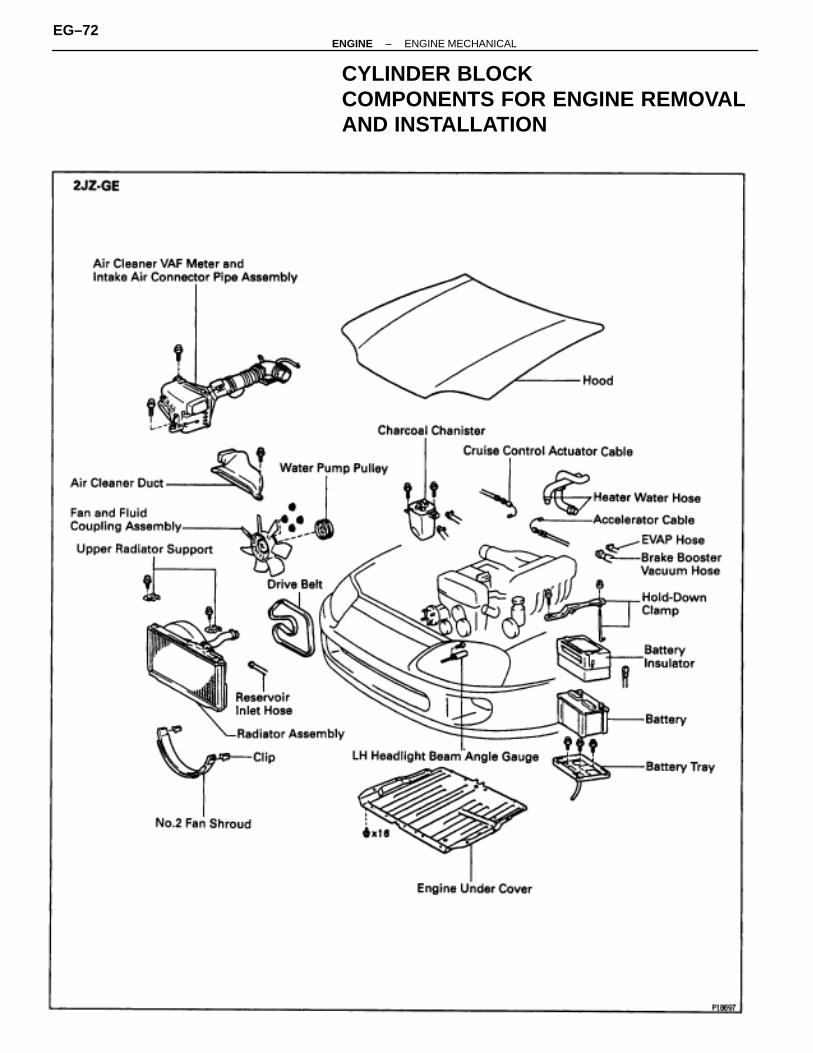
CYLINDER BLOCKCOMPONENTS FOR ENGINE REMOVALAND INSTALLATION
EG–72–ENGINE ENGINE MECHANICAL

–ENGINE ENGINE MECHANICALEG–73
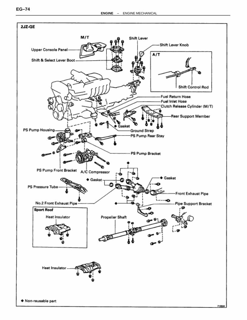
EG–74–ENGINE ENGINE MECHANICAL

–ENGINE ENGINE MECHANICALEG–75

EG–76–ENGINE ENGINE MECHANICAL

–ENGINE ENGINE MECHANICALEG–77

ENGINE REMOVAL (2JZ–GE)1. REMOVE HOOD2. REMOVE RADIATOR ASSEMBLY
(See radiator removal in Cooling System)3. DRAIN ENGINE OIL4. DRAIN FUEL FROM FUEL TANK5. DISCONNECT CONTROL CABLES FROM THROTTLE
BODYDisconnect these cables:
• Accelerator cable• Cruise control actuator cable
6. REMOVE AIR CLEANER, VAF METER AND INTAKE AIRCONNECTOR PIPE ASSEMBLY
(a) Disconnect the high–tension cord from the ignition coil.(b) Disconnect the high–tension cord from the clamp on the air
cleaner.(c) Disconnect the VAF meter connector.(d) Disconnect the engine wire from the VAF meter.
(e) Disconnect these hoses:(1) PS air hose from No.4 timing belt cover(2) PCV hose from No.2 cylinder head cover
(f) Loosen the hose clamp bolt holding the intake air connectorpipe to the throttle body.
(g) Remove the 3 bolts, air cleaner, VAF meter and intake airconnector pipe assembly.
7. REMOVE DRIVE BELT, FAN, FLUID COUPLINGASSEMBLY AND WATER PUMP PULLEY(See step 6 in water pump removal in Cooling System)
8. REMOVE CHARCOAL CANISTER9. DISCONNECT HEATER WATER HOSES10. DISCONNECT BRAKE BOOSTER VACUUM HOSE11. DISCONNECT EVAP HOSE
12. DISCONNECT WIRES AND CONNECTORS(a) Disconnect the noise filter connector.(b) Disconnect the ignition coil connector.(c) Disconnect the engine wire from the wire clamp.
EG–78–ENGINE ENGINE MECHANICAL

(d) Remove the rubber cap and nut, and disconnect thegenerator wire.
(e) Disconnect these connectors:(1) Connector from engine room main wire(2) Igniter connector(3) Theft deterrent horn connector
(f) Disconnect the engine wire from the 2 wire clamps.
(g) Disconnect the wire clamp and PS solenoid valve connector.
(h) Remove the bolt, and disconnect the ground strap from thecylinder block.
(i) Remove the rubber cap and nut, and disconnect the starterwire.
–ENGINE ENGINE MECHANICALEG–79

13. DISCONNECT FUEL HOSES(a) Remove the union bolt and 2 gaskets, disconnect the fuel
inlet hose.HINT:• Put a suitable container or shop rag under the fuel pipe
support.• Slowly loosen the union bolt.
(b) Suspend the hose union end upward.
(c) Disconnect the fuel return hose from the oil dipstick guide.(d) Disconnect the fuel return hose from the fuel return hose.
Plug the hose end.14. REMOVE ENGINE WIRE BRACKET
Remove the bolt and bracket, and disconnect the engine wirefrom the intake manifold stay.
15. DISCONNECT PS PUMP WITHOUT DISCONNECTINGHOSES
(a) Remove the 3 bolts, plate washer and pump front bracket.
(b) Disconnect these hoses:(1) Air hose from No.4 timing belt cover(2) Air hose from air intake chamber
(c) Disconnect the pump housing from the pump bracket.HINT: Put aside the pump housing, and suspend it.
(d) Remove the 2 bolts and pump rear stay.
(e) Remove the 2 bolts and pump bracket.
EG–80–ENGINE ENGINE MECHANICAL
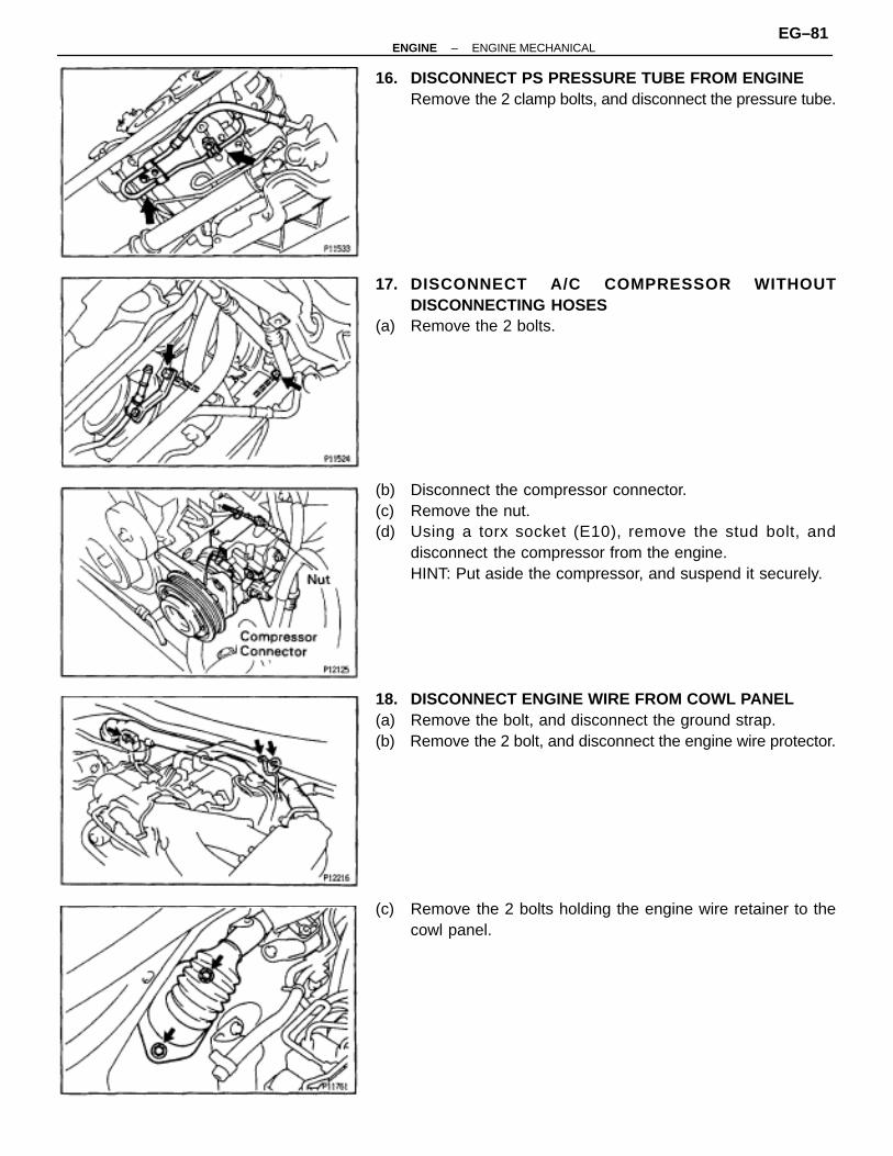
16. DISCONNECT PS PRESSURE TUBE FROM ENGINERemove the 2 clamp bolts, and disconnect the pressure tube.
17. DISCONNECT A/C COMPRESSOR WITHOUTDISCONNECTING HOSES
(a) Remove the 2 bolts.
(b) Disconnect the compressor connector.(c) Remove the nut.(d) Using a torx socket (E10), remove the stud bolt, and
disconnect the compressor from the engine.HINT: Put aside the compressor, and suspend it securely.
18. DISCONNECT ENGINE WIRE FROM COWL PANEL(a) Remove the bolt, and disconnect the ground strap.(b) Remove the 2 bolt, and disconnect the engine wire protector.
(c) Remove the 2 bolts holding the engine wire retainer to thecowl panel.
–ENGINE ENGINE MECHANICALEG–81
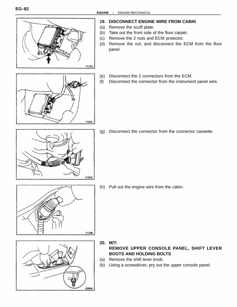
19. DISCONNECT ENGINE WIRE FROM CABIN(a) Remove the scuff plate.(b) Take out the front side of the floor carpet.(c) Remove the 2 nuts and ECM protector.(d) Remove the nut, and disconnect the ECM from the floor
panel.
(e) Disconnect the 2 connectors from the ECM.(f) Disconnect the connector from the instrument panel wire.
(g) Disconnect the connector from the connector cassette.
(h) Pull out the engine wire from the cabin.
20. M/T:REMOVE UPPER CONSOLE PANEL, SHIFT LEVERBOOTS AND HOLDING BOLTS
(a) Remove the shift lever knob.(b) Using a screwdriver, pry out the upper console panel.
EG–82–ENGINE ENGINE MECHANICAL

(c) Remove the 4 bolts holding the lever boot to the transmissioncover.
(d) Remove the shift and select lever boots.
(e) Remove the 4 bolts holding the shift lever to the shift leverretainer.
21. M/T:DISCONNECT CLUTCH RELEASE CYLINDER ANDGROUND STRAP FROM TRANSMISSION
(a) Remove the 2 bolts and clutch release cylinder.(b) Remove the bolt, and disconnect the ground strap.
22. REMOVE NO.2 EXHAUST PIPE(a) Remove the 2 bolts and nuts holding the No.2 front exhaust
pipe to the front exhaust pipe.(b) Remove the 2 bolts and pipe support bracket.(c) Remove the gasket, and disconnect the front exhaust pipe.
(d) Remove the 4 nuts, No.2 front exhaust pipe and 2 gaskets.23. REMOVE EXHAUST PIPE HEAT INSULATOR24. REMOVE PROPELLER SHAFT
(See propeller shaft removal in Propeller Shaft)
–ENGINE ENGINE MECHANICALEG–83

25. A/T:DISCONNECT TRANSMISSION CONTROL RODRemove the nut, and disconnect the control rod from the shiftlever.
26. M/T:REMOVE TRANSMISSION SHIFT LEVER
(a) Remove the bolt and nut.(b) Remove the transmission shift lever, inside of vehicle.27. PLACE JACK UNDER TRANSMISSION
NOTICE (A/T): Be sure to put a wooden block between the jackand the transmission oil pan to prevent damage.
28. REMOVE REAR SUPPORT MEMBER(a) Remove the 4 nuts holding the member to the engine rear
mounting insulator.(b) Remove the 4 bolts and rear support member.
29. REMOVE ENGINE AND TRANSMISSION ASSEMBLYFROM VEHICLE
(a) Attach the engine hoist chain to the 2 engine hangers.
(b) Remove the 2 nuts holding the engine front mountinginsulators to the front suspension crossmember.
EG–84–ENGINE ENGINE MECHANICAL

(c) Lift the engine out of the vehicle slowly and carefully.NOTICE: Remove the engine and transmission assembly care-fully without damaging the shift lever retainer (M/ T), A/C com-pressor or PS solenoid valve.
(d) Make sure the engine is clear of all wiring, hoses and cables.(e) Place the engine and transmission assembly onto the stand.
ENGINE REMOVAL (2JZ–GTE)1. REMOVE HOOD2. REMOVE RADIATOR ASSEMBLY
(See radiator removal in Cooling System)3. DRAIN ENGINE OIL4. DRAIN FUEL FROM FUEL TANK5. REMOVE NO.1 AIR HOSE6. DISCONNECT CONTROL CABLES FROM THROTTLE
BODY
Disconnect these cables:• Accelerator cable• Cruise control actuator cable
7. REMOVE AIR CLEANER AND MAF METER ASSEMBLY(a) Remove the 3 bolts.(b) Loosen the hose clamp, disconnect the air hose from the
intake air connector.(c) Disconnect the MAF meter wire from the clamp on the air
cleaner case.(d) Disconnect the MAF meter connector, and remove the air
cleaner and MAF meter assembly.8. M/T:
REMOVE DRIVE BELT TENSIONER DAMPER(See step 2 in timing belt removal)
9. REMOVE DRIVE BELT, FAN, FLUID COUPLINGASSEMBLY AND WATER PUMP PULLEY(See step 6 in water pump removal in Cooling System)
10. REMOVE CHARCOAL CANISTER
11. DISCONNECT HEATER WATER HOSES12. DISCONNECT BRAKE BOOSTER VACUUM HOSE13. DISCONNECT EVAP HOSE
–ENGINE ENGINE MECHANICALEG–85
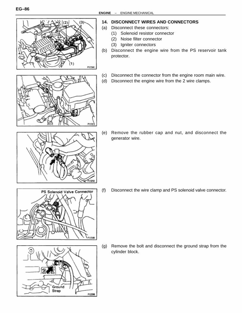
14. DISCONNECT WIRES AND CONNECTORS(a) Disconnect these connectors:
(1) Solenoid resistor connector(2) Noise filter connector(3) Igniter connectors
(b) Disconnect the engine wire from the PS reservoir tankprotector.
(c) Disconnect the connector from the engine room main wire.(d) Disconnect the engine wire from the 2 wire clamps.
(e) Remove the rubber cap and nut, and disconnect thegenerator wire.
(f) Disconnect the wire clamp and PS solenoid valve connector.
(g) Remove the bolt and disconnect the ground strap from thecylinder block.
EG–86–ENGINE ENGINE MECHANICAL

(h) Disconnect the starter wire from the LH engine mountingbracket.
(i) Remove the rubber cap and nut, and disconnect the starterwire.
15. DISCONNECT FUEL HOSES(a) Remove the union bolt and 2 gaskets, and disconnect the
fuel inlet hose.HINT:• Put a suitable container or shop rag under the fuel pipe
support.• Slowly loosen the union bolt.
(b) Suspend the hose union end upward.
(c) Disconnect the fuel return hose from the clamp of the dipstickguide.
(d) Disconnect the fuel return hose from the fuel return pipe. Plugthe hose end.
16. DISCONNECT PS PUMP WITHOUT DISCONNECTINGHOSES
(a) Disconnect these hoses:(1) Air hose from throttle body(2) Air hose from air intake chamber
(b) Remove the 2 bolts, and disconnect the pump housing fromthe pump bracket.HINT: Put aside the pump housing, and suspend it securely.
(c) Remove the 3 bolts and pump bracket.
–ENGINE ENGINE MECHANICALEG–87
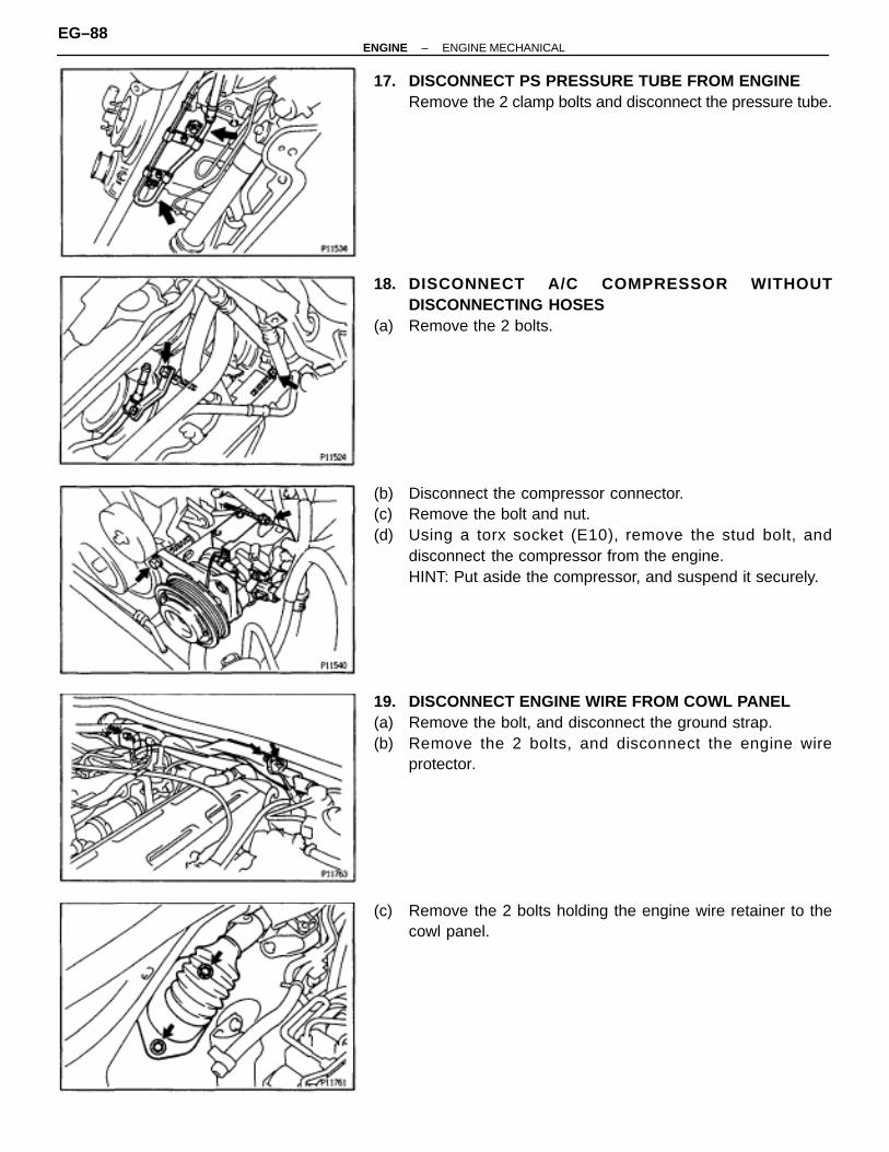
17. DISCONNECT PS PRESSURE TUBE FROM ENGINERemove the 2 clamp bolts and disconnect the pressure tube.
18. DISCONNECT A/C COMPRESSOR WITHOUTDISCONNECTING HOSES
(a) Remove the 2 bolts.
(b) Disconnect the compressor connector.(c) Remove the bolt and nut.(d) Using a torx socket (E10), remove the stud bolt, and
disconnect the compressor from the engine.HINT: Put aside the compressor, and suspend it securely.
19. DISCONNECT ENGINE WIRE FROM COWL PANEL(a) Remove the bolt, and disconnect the ground strap.(b) Remove the 2 bolts, and disconnect the engine wire
protector.
(c) Remove the 2 bolts holding the engine wire retainer to thecowl panel.
EG–88–ENGINE ENGINE MECHANICAL

20. DISCONNECT ENGINE WIRE FROM CABIN(a) Remove the scuff plate.(b) Take out the front side of the floor carpet.(c) Remove the 2 nuts and ECM protector.(d) Remove the nut, and disconnect the ECM from the floor
panel.
(e) Disconnect the 2 connectors from the ECM.(f) Disconnect the connector from the TRAC ECU.(g) Disconnect the connector from the instrument panel wire.
(h) Disconnect the connectors from the connector cassette.
(j) Pull out the engine wire from the cabin.
21. M/T:REMOVE UPPER CONSOLE PANEL, SHIFT LEVERBOOTS AND HOLDING BOLTS
(a) Remove the shift lever knob.(b) Using a screwdriver, pry out the upper console panel.
–ENGINE ENGINE MECHANICALEG–89

(c) Remove the 4 bolts holding the lever boot to the transmissioncover.
(d) Remove the shift & select lever boots.
(e) Remove the 4 bolts holding the shift lever to the shift leverretainer.
22. M/T:DISCONNECT CLUTCH RELEASE CYLINDER ANDGROUND STRAP FROM TRANSMISSION
(a) Remove the 2 bolts, and disconnect clutch release cylinder.(b) Remove the bolt, and disconnect the clutch line tube.(c) Remove the bolt, and disconnect ground strap.
23. DISCONNECT SUB HEATED OXYGEN SENSOR FROMFRONT EXHAUST PIPERemove the 2 nuts and sensor cover, and disconnect oxygensensor and gasket.
24. REMOVE EXHAUST PIPE ASSEMBLY(a) Remove the 2 bolts and nuts holding the front exhaust pipe
to the No.2 front exhaust pipe.(b) Remove the 2 bolts and pipe support bracket.(c) Remove the gasket, and disconnect the front exhaust pipe.
EG–90–ENGINE ENGINE MECHANICAL

(d) Disconnect the hook of the tailpipe from the 2 rings.(e) Disconnect the 2 rings on the exhaust pipe from the exhaust
pipe brackets, and remove the exhaust pipe assembly.
25. REMOVE NO.2 FRONT EXHAUST PIPERemove the 3 nuts, front exhaust pipe and gasket.
26. REMOVE EXHAUST PIPE HEAT INSULATORRemove the 4 nuts and heat insulator.
27. REMOVE REAR CENTER FLOOR CROSSMEMBERBRACERemove the 4 bolts (Normal roof) or 6 bolts (Sport Roof) andcrossmember brace.
28. REMOVE PROPELLER SHAFT(See propeller shaft removal in Propeller Shaft)
29. A/T:DISCONNECT TRANSMISSION CONTROL RODRemove the nut, and disconnect the control rod from the shiftlever.
–ENGINE ENGINE MECHANICALEG–91

30. M/T:REMOVE TRANSMISSION SHIFT LEVER
(a) Remove the bolt and nut.(b) Remove the transmission shift lever, inside of vehicle.31. PLACE JACK UNDER TRANSMISSION
NOTICE (A/T): Be sure to put a wooden block between the jackand the transmission oil pan to prevent damage.
32. REMOVE REAR SUPPORT MEMBER(a) Remove the 4 nuts holding the member to the engine rear
mounting insulator.(b) Remove the 4 bolts and rear support member.
33. REMOVE ENGINE AND TRANSMISSION ASSEMBLYFROM VEHICLE
(a) Attach the engine hoist chain to the 2 engine hangers.
(b) Remove the 2 nuts holding the engine front mountinginsulators to the front suspension crossmember.
(c) Lift the engine out of the vehicle slowly and carefully.NOTICE: Remove the engine and transmission assembly care-fully without damaging the shift lever retainer (M/ T), A/C com-pressor or PS solenoid valve
(d) Make sure the engine is clear of all wiring, hoses and cables.(e) Place the engine and transmission assembly onto the stand.
EG–92–ENGINE ENGINE MECHANICAL

COMPONENTS FOR ENGINE &TRANSMISSION SEPERATION ANDASSEMBLY
–ENGINE ENGINE MECHANICALEG–93

ENGINE & TRANSMISSION SEPARATION
1. A/T:REMOVE OIL DIPSTICK GUIDE FOR TRANSMISSION
(a) Remove the bolt.(b) Pull out the dipstick and guide from the transmission.(c) Remove the O–ring from the dipstick guide.
2. DISCONNECT ENGINE WIRE FROM TRANSMISSION(a) Disconnect the connectors.(b) Disconnect the wire clamps from the brackets.3. REMOVE STARTER(a) Disconnect the starter connector.(b) Remove the 2 bolts, engine wire bracket and starter.
4. 2JZ–GE A/T:DISCONNECT THROTTLE CABLE
(a) Disconnect the throttle cable from the throttle body.(b) Disconnect the throttle cable from the cable bracket on the
cylinder head.5. A/T:
REMOVE OIL COOLER TUBES FOR TRANSMISSION(a) Remove the 2 hose clamp bolts and tube clamp bolt.(b) Loosen the 2 union nuts, and remove the oil cooler tubes.
EG–94–ENGINE ENGINE MECHANICAL

6. 2JZ–GTE M/T:REMOVE CLUTCH COVER SET BOLTS
(a) Remove the 2 bolts and service hole cover.(b) Place the matchmarks on the flywheel and clutch cover.(c) Remove the 6 bolts.
7. A/T:REMOVE TORQUE CONVERTER CLUTCH MOUNTINGBOLTS
(a) Remove the hole plug.(b) Turn the crankshaft to gain access to each bolt.
Remove the 6 bolts.
8. SEPARATE ENGINE AND TRANSMISSIONRemove the 6 bolts and transmission.HINT: The ”17” is 17 mm head bolt, and ”14” is 14 mm headbolt.
9. 2JZ–GE M/T:REMOVE CLUTCH COVER AND DISC
(a) Place matchmarks on the flywheel and clutch cover.(b) Loosen each bolt one turn at a time until spring tension is
released.(c) Remove the bolts, and pull off the clutch cover with the clutch
disc.NOTICE: Do not drop the clutch disc.
–ENGINE ENGINE MECHANICALEG–95
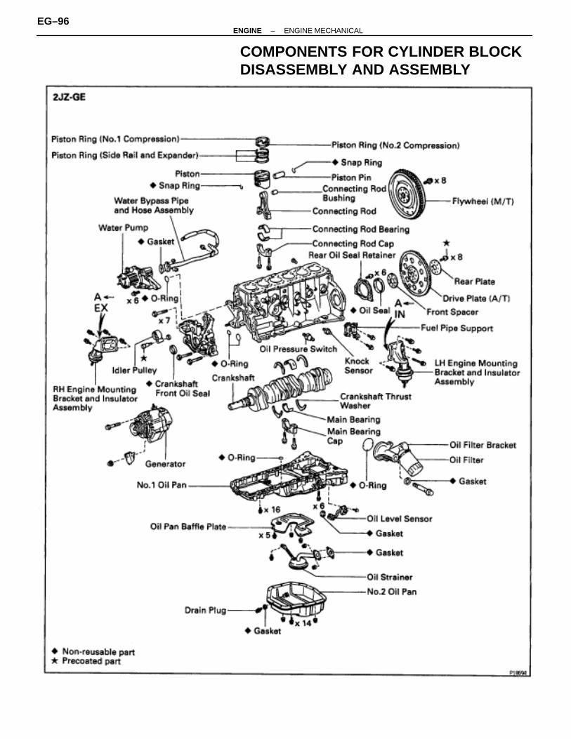
COMPONENTS FOR CYLINDER BLOCKDISASSEMBLY AND ASSEMBLY
EG–96–ENGINE ENGINE MECHANICAL

–ENGINE ENGINE MECHANICALEG–97

PREPARATION FOR DISASSEMBLY1. M/T:
REMOVE FLYWHEEL2. A/T:
REMOVE DRIVE PLATE3. INSTALL ENGINE TO ENGINE STAND FOR
DISASSEMBLY4. REMOVE GENERATOR
5. REMOVE TIMING BELT AND PULLEYS(See timing belt removal)
6. REMOVE CYLINDER HEAD(See cylinder head removal)
7. REMOVE OIL FILTER(See oil and filter replacement in Lubrication System)
8. 2JZ–GTE:REMOVE OIL COOLER(See oil cooler removal in Lubrication System)
9. REMOVE NO.2 WATER BYPASS PIPE(a) 2JZ–GE:
Remove the bolt, 2 nuts, water bypass pipe and gasket.(b) 2JZ–GTE:
Remove the 2 bolts, 2 nuts, water bypass pipe and gasket.
10. REMOVE OIL FILTER BRACKETRemove the union bolt, gasket, oil filter bracket and O –ring.
11. REMOVE LH ENGINE MOUNTING BRACKET ANDINSULATOR ASSEMBLY
12. REMOVE FUEL PIPE SUPPORT
EG–98–ENGINE ENGINE MECHANICAL
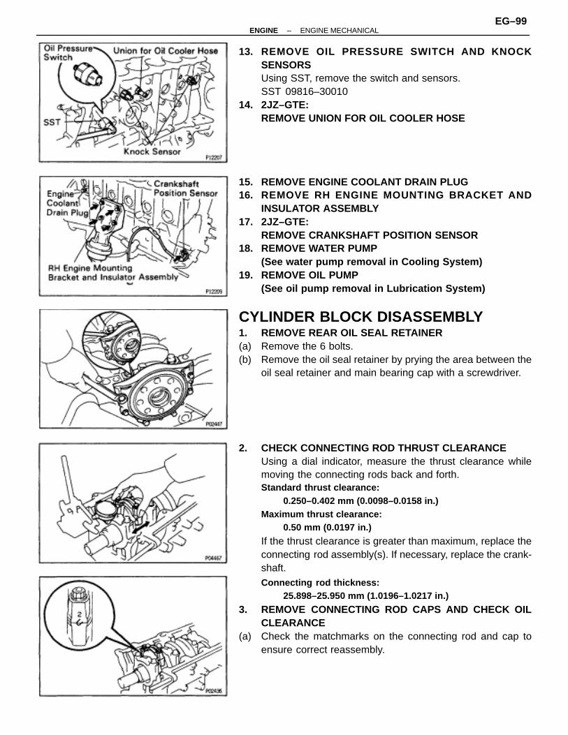
13. REMOVE OIL PRESSURE SWITCH AND KNOCKSENSORSUsing SST, remove the switch and sensors.SST 09816–30010
14. 2JZ–GTE:REMOVE UNION FOR OIL COOLER HOSE
15. REMOVE ENGINE COOLANT DRAIN PLUG16. REMOVE RH ENGINE MOUNTING BRACKET AND
INSULATOR ASSEMBLY17. 2JZ–GTE:
REMOVE CRANKSHAFT POSITION SENSOR18. REMOVE WATER PUMP
(See water pump removal in Cooling System)19. REMOVE OIL PUMP
(See oil pump removal in Lubrication System)
CYLINDER BLOCK DISASSEMBLY1. REMOVE REAR OIL SEAL RETAINER(a) Remove the 6 bolts.(b) Remove the oil seal retainer by prying the area between the
oil seal retainer and main bearing cap with a screwdriver.
2. CHECK CONNECTING ROD THRUST CLEARANCEUsing a dial indicator, measure the thrust clearance whilemoving the connecting rods back and forth.Standard thrust clearance:
0.250–0.402 mm (0.0098–0.0158 in.)Maximum thrust clearance:
0.50 mm (0.0197 in.)
If the thrust clearance is greater than maximum, replace theconnecting rod assembly(s). If necessary, replace the crank-shaft.Connecting rod thickness:
25.898–25.950 mm (1.0196–1.0217 in.)
3. REMOVE CONNECTING ROD CAPS AND CHECK OILCLEARANCE
(a) Check the matchmarks on the connecting rod and cap toensure correct reassembly.
–ENGINE ENGINE MECHANICALEG–99

(b) Remove the connecting rod cap bolts.
(c) Using the 2 removed connecting rod bolts, remove theconnecting rod cap and lower bearing by wiggling theconnecting rod cap right and left.HINT: Keep the lower bearing inserted with the connectingrod cap.
(d) Clean the crank pin and bearings.(e) Check the crank pin and bearing for pitting and scratches.
If the crank pin or bearing is damaged, replace the bearings.If necessary, replace the crankshaft.
(f) Lay a strip of Plastigage across the crank pin.
(g) Install the connecting rod cap with the 2 bolts.(See step 8 in cylinder block assembly)Torque:
1st29 N⋅m (300 kgf ⋅cm, 22 ft ⋅lbf)
2ndTurn 90 °
NOTICE: Do not turn the crankshaft.(h) Remove the 2 bolts, connecting rod cap and lower bearing.
(See procedure (b) and (c) above)
EG–100–ENGINE ENGINE MECHANICAL

(i) Measure the Plastigage at its widest point.Standard oil clearance:
STD.035–0.053 mm (0.0014–0.0021 in.)
U/S 0.25.040–0.078 mm (0.0016–0.0031 in.)
Maximum oil clearance.STD
.08 mm (0.0031 in.)U/S 0.25
.09 mm (0.0035 in.)
If the oil clearance is greater than maximum, replace thebearings. If necessary, grind or replace the crankshaft.HINT: If using a standard bearing, replace with one havingthe same number. If the number of the bearing cannot be de-termined, select the correct bearing by adding together thenumbers imprinted on the connecting rod cap and crank-shaft, then selecting the bearing with the same number as thetotal. There are 5 sizes of standard bearings, marked ”1”, ”2”,”3”, ”4” and ”5” accordingly.
ÑÑÑÑÑÑÑÑÑÑÑÑÑÑÑÑ
ÑÑÑÑÑÑÑÑÑÑÑÑÑÑÑÑÑÑÑÑÑÑÑÑÑÑÑÑÑÑ
Number mark
ÑÑÑÑÑÑÑÑÑÑÑÑÑÑÑÑ
Connecting rod capÑÑÑÑÑÑÑÑÑÑ
1ÑÑÑÑÑÑÑÑÑÑÑÑ
2ÑÑÑÑÑÑÑÑÑÑÑÑ
3ÑÑÑÑÑÑÑÑÑÑÑÑÑÑÑÑÑÑÑÑÑÑÑÑ
CrankshaftÑÑÑÑÑÑ
0ÑÑÑÑÑÑÑÑÑ
1ÑÑÑÑÑÑ
2ÑÑÑÑÑÑÑÑÑ
0ÑÑÑÑÑÑÑÑÑ
1ÑÑÑÑÑÑ
2ÑÑÑÑÑÑÑÑÑ
0ÑÑÑÑÑÑ
1ÑÑÑÑÑÑÑÑÑ
2
ÑÑÑÑÑÑÑÑÑÑÑÑÑÑÑÑ
Use bearing ÑÑÑÑ
1ÑÑÑÑÑÑ
2 ÑÑÑÑ
3ÑÑÑÑÑÑ
2ÑÑÑÑÑÑ
3 ÑÑÑÑ
4ÑÑÑÑÑÑ
3 ÑÑÑÑ
4ÑÑÑÑÑÑ
5
EXAMPLE: Connecting rod cap ”3” +Crankshaft ”1” = Totalnumber 4 (Use bearing ”4”)
Reference:Connecting rod big end inside diameter:
Mark ”1”55.025–55.031 mm (2.1663–2.1666 in.)
Mark ”2”55.031–55.037 mm (2.1666–2.1668 in.)
Mark ”3”55.037–55.043 mm (2.1668–2.1670 in.)
Crankshaft crank pin diameter:Mark ”0”
51.994–52.000 mm (2.0470–2.0472 in.)Mark ”1”
51.988–51.994 mm (2.0468–2.0470 in.)Mark ”2”
51.982–51.988 mm (2.0465–2.0468 in.)
–ENGINE ENGINE MECHANICALEG–101

Bearing center wall thickness:Mark ”1”
1.492–1.495 mm (0.0587–0.0589 in.)Mark ”2”
1.495–1.498 mm (0.0589–0.0590 in.)Mark ”3”
1.498–1.501 mm (0.0590–0.0591 in.)Mark ”4”
1.501–1.504 mm (0.0591–0.0592 in.)Mark ”5”
1.504–1.507 mm (0.0592–0.0593 in.)
(j) Completely remove the Plastigage.4. REMOVE PISTON AND CONNECTING ROD
ASSEMBLIES(a) Using a ridge reamer, remove all the carbon from the top of
the cylinder.(b) Push the piston, connecting rod assembly and upper bearing
through the top of the cylinder block.HINT:
• Keep the bearings, connecting rod and cap together.• Arrange the piston and connecting rod assemblies in
correct order.5. CHECK CRANKSHAFT THRUST CLEARANCE
Using a dial indicator, measure the thrust clearance while pry-ing the crankshaft back and forth with a screwdriver.Standard thrust clearance:
0.020–0.220 mm (0.0008–0.0087 in.)Maximum thrust clearance:
0.30 mm (0.0118 in.)
If the thrust clearance is greater than maximum, replace thethrust washers as a set.Thrust washer thickness:
1.940–1.990 mm (0.0764–0.0783 in.)
6. REMOVE MAIN BEARING CAPS AND CHECK OILCLEARANCE
(a) Uniformly loosen and remove the 14 main bearing cap bolts,in severval passes, in the sequence shown.
(b) Using the removed main bearing cap bolts, pry the mainbearing cap back and forth, and remove the main bearingcaps, lower bearings and lower thrust washers (No.4 mainbearing cap only).HINT:• Keep the lower bearing and main bearing cap together.• Arrange the main bearing caps and lower thrust
washers in correct order.
EG–102–ENGINE ENGINE MECHANICAL
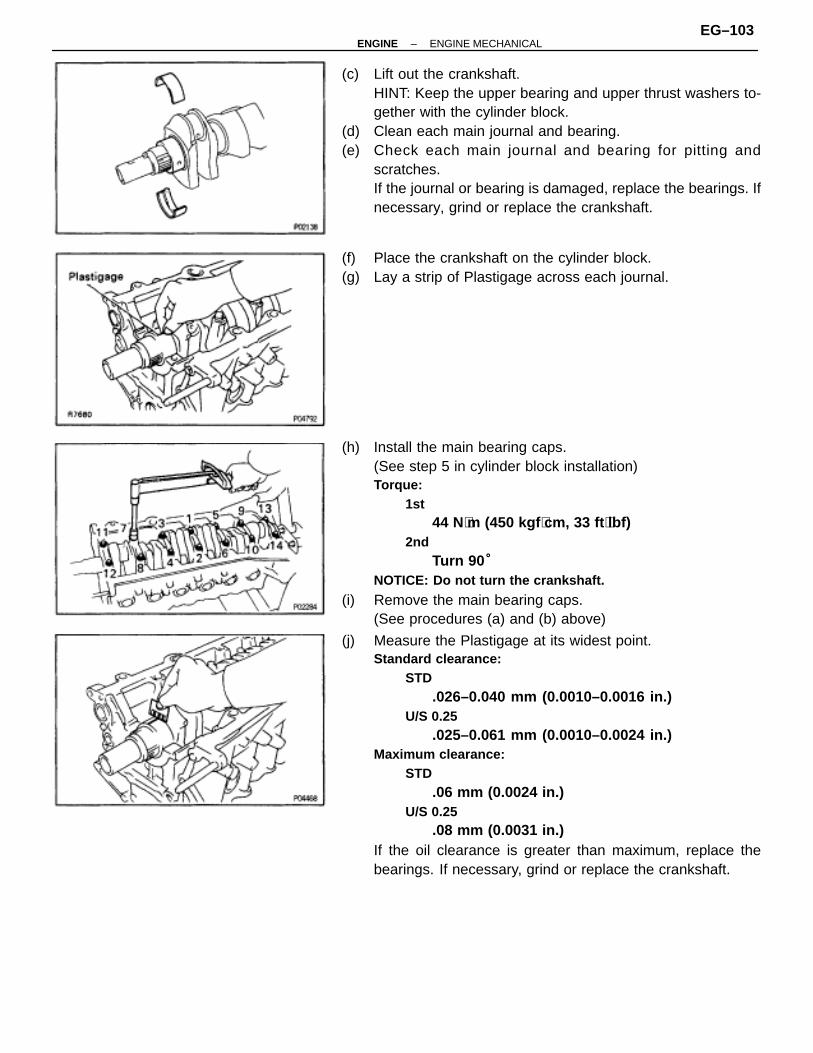
(c) Lift out the crankshaft.HINT: Keep the upper bearing and upper thrust washers to-gether with the cylinder block.
(d) Clean each main journal and bearing.(e) Check each main journal and bearing for pitting and
scratches.If the journal or bearing is damaged, replace the bearings. Ifnecessary, grind or replace the crankshaft.
(f) Place the crankshaft on the cylinder block.(g) Lay a strip of Plastigage across each journal.
(h) Install the main bearing caps.(See step 5 in cylinder block installation)Torque:
1st44 N⋅m (450 kgf ⋅cm, 33 ft ⋅lbf)
2ndTurn 90 °
NOTICE: Do not turn the crankshaft.
(i) Remove the main bearing caps.(See procedures (a) and (b) above)
(j) Measure the Plastigage at its widest point.Standard clearance:
STD.026–0.040 mm (0.0010–0.0016 in.)
U/S 0.25.025–0.061 mm (0.0010–0.0024 in.)
Maximum clearance:STD
.06 mm (0.0024 in.)U/S 0.25
.08 mm (0.0031 in.)If the oil clearance is greater than maximum, replace thebearings. If necessary, grind or replace the crankshaft.
–ENGINE ENGINE MECHANICALEG–103

HINT: If using a standard bearing, replace with one havingthe same number. If the number of the bearing cannot be de-termined, select the correct bearing by adding together thenumbers imprinted on the cylinder block and crankshaft, thenrefer to the table below for the appropriate bearing number.There are 5 sizes of standard bearings, marked ”1”, ”2”, ”3”,”4” and ”5” accordingly.
ÑÑÑÑÑÑÑÑÑÑÑÑÑÑÑÑÑÑÑÑÑÑÑÑÑÑÑ
ÑÑÑÑÑÑÑÑÑÑÑÑÑÑÑÑÑÑÑÑÑÑÑÑÑÑÑÑÑÑÑÑÑÑÑÑÑÑÑÑÑÑ
Total number ” ”:Number mark
ÑÑÑÑÑÑÑÑÑÑÑÑÑÑÑÑÑÑ
Cylinder block (A)+
ÑÑÑÑÑÑÑÑ0 2
ÑÑÑÑÑÑ3 5
ÑÑÑÑÑÑÑÑ6 8
ÑÑÑÑÑÑ9 11
ÑÑÑÑÑÑÑÑ12 14ÑÑÑÑÑÑÑÑÑ
ÑÑÑÑÑÑÑÑÑÑÑÑÑÑÑÑÑÑ
+Crankshaft (B) =
ÑÑÑÑÑÑÑÑÑÑÑÑ
0–2 ÑÑÑÑÑÑÑÑÑ
3–5ÑÑÑÑÑÑÑÑÑÑÑÑ
6–8 ÑÑÑÑÑÑÑÑÑ
9–11ÑÑÑÑÑÑÑÑÑÑÑÑ
12–14
ÑÑÑÑÑÑÑÑÑÑÑÑÑÑÑÑÑÑ
Use bearing ”1” ”2” ”3” ”4” ”5”ÑÑÑÑÑÑÑÑÑ
Use bearing ”1” ”2” ”3” ”4” ”5”
EXAMPLE: Cylinder block ”3” (A)+ Crankshaft ”4”(B)= Total number 7 (Use bearing ”3”)
Reference:Cylinder block main journal bore diameter (A):
Mark ”0”66.020–66.022 mm (2.59922–2.59929 in.)
Mark ”1”66.022–66.024 mm (2.59929–2.59936 in.)
Mark ”2”66.024–66.026 mm (2.59936–2.59944 in.)
Mark ”3”66.026–66.028 mm (2.59944–2.59952 in.)
Mark ”4”66.028–66.030 mm (2.59952–2.59960 in.)
Mark ”5”66.030–66.032 mm (2.59960–2.59968 in.)
Mark ”6”66.032–66.034 mm (2.59968–2.59976 in.)
Mark ”7”66.034–66.036 mm (2.59976–2.59984 in.)
Crankshaft main journal diameter (B):Mark ”0”
61.998–62.000 mm (2.44086–2.44094 in.)Mark ”1”
61.996–61.998 mm (2.44078–2.44086 in.)Mark ”2”
61.994–61.996 mm (2.44070–2.44078 in.)Mark ”3”
61.992–61.994 mm (2.44063–2.44070 in.)Mark ”4”
61.990–61.992 mm (2.44055–2.44063 in.)Mark ”5”
61.988–61.990 mm (2.44047–2.44055 in.)
EG–104–ENGINE ENGINE MECHANICAL

Mark ”6”61.986–61.988 mm (2.44039–2.44047 in.)
Mark ”7”61.984–61.986 mm (2.44031–2.44039 in.)
Bearing center wall thickness:Mark ”1”
1.994–1.997 mm (0.0785–0.0786 in.)Mark ”2”
1.997–2.000 mm (0.0786–0.0787 in.)Mark ”3”
2.000–2.003 mm (0.0787–0.0789 in.)Mark ”4”
2.003–2.006 mm (0.0789–0.0790 in.)Mark ”5”
2.006–2.009 mm (0.0790–0.0791 in.)Standard sized Bearing Selection chart
ÑÑÑÑÑÑÑÑÑÑÑÑ
Crankshaft ÑÑÑÑÑÑÑÑÑÑÑÑÑÑÑÑÑÑÑÑÑÑÑÑ
Cylinder block number mark
ÑÑÑÑÑÑÑÑÑÑÑÑ
number markÑÑÑÑ
0ÑÑÑÑÑÑ
1 ÑÑÑÑ
2ÑÑÑÑ
3ÑÑÑÑÑÑ
4 ÑÑÑÑ
5ÑÑÑÑ
6ÑÑÑÑÑÑ
7
ÑÑÑÑÑÑ0 1 1 1 2 2 2 3 3ÑÑÑÑÑÑÑÑÑÑÑÑ
0 1 1 1 2 2 2 3 3ÑÑÑÑÑÑÑÑÑÑÑÑ
1 1 1 2 2 2 3 3 3ÑÑÑÑÑÑ
1 1 1 2 2 2 3 3 3ÑÑÑÑÑÑÑÑÑÑÑÑ
2 1 2 2 2 3 3 3 4ÑÑÑÑÑÑ
2 1 2 2 2 3 3 3 4ÑÑÑÑÑÑÑÑÑÑÑÑ3 2 2 2 3 3 3 4 4ÑÑÑÑÑÑ3 2 2 2 3 3 3 4 4ÑÑÑÑÑÑÑÑÑÑÑÑ4 2 2 3 3 3 4 4 4ÑÑÑÑÑÑÑÑÑÑÑÑ
4 2 2 3 3 3 4 4 4
ÑÑÑÑÑÑ5 2 3 3 3 4 4 5 5ÑÑÑÑÑÑÑÑÑÑÑÑ
5 2 3 3 3 4 4 5 5
ÑÑÑÑÑÑ6 3 3 3 4 4 5 5 5ÑÑÑÑÑÑÑÑÑÑÑÑ
6 3 3 3 4 4 5 5 5
ÑÑÑÑÑÑ7 3 3 4 4 5 5 5 5ÑÑÑÑÑÑÑÑÑÑÑÑ
7 3 3 4 4 5 5 5 5
EXAMPLE: Cylinder block ”3” Crankshaft ”4”= Use bearing ”3”
(k) Completely remove the Plastigage.7. REMOVE CRANKSHAFT(a) Lift out the crankshaft(b) Remove the upper bearings and upper thrust washers from
the cylinder block.HINT: Arrange the main bearing caps, bearings and thrustwashers in the correct order.
8. 2JZ–GTE:REMOVE OIL NOZZLES (WITH RELIEF VALVES)Using a 5 mm hexagon wrench, remove the bolt and oilnozzle. Remove the 6 oil nozzles.
–ENGINE ENGINE MECHANICALEG–105

CYLINDER BLOCK INSPECTION1. CLEAN CYLINDER BLOCKA. Remove gasket material
Using a gasket scraper, remove all the gasket material fromthe cylinder block surface.
B. Clean cylinder blockUsing a soft brush and solvent, thoroughly clean the cylinderblock.
2. INSPECT CYLINDER BLOCK SURFACE FOR FLATNESSUsing precision straight edge and feeler gauge, measure thesurfaces of the cylinder block for warpage.Maximum warpage:
0.07 mm (0.0028 in.)
If warpage is greater than maximum, replace the cylinderblock.
3. INSPECT CYLINDER FOR VERTICAL SCRATCHESVisually check the cylinder for vertical scratches.If deep scratches are present, replace the cylinder block.
4. INSPECT CYLINDER BORE DIAMETERUsing a cylinder gauge, measure the cylinder bore diameterat positions A, B and C in the thrust and axial directions.Standard diameter:
86.000–86.013 mm (3.3858–3.3863 in.)Maximum diameter:
86.02 mm (3.3866 in.)
If the diameter is greater than maximum, replace the cylinderblock.
EG–106–ENGINE ENGINE MECHANICAL

5. REMOVE CYLINDER RIDGEIf the wear is less than 0.2 mm (0.008 in.), using a ridge ream-er, grind the top of the cylinder.
6. INSPECT MAIN BEARING CAP BOLTSUsing vernier calipers, measure the minimum diameter of thecompressed thread at the measuring point.Standard diameter:
9.96–9.97 mm (0.3921–0.3925 in.)Minimum diameter:
9.7 mm (0.382 in.)
If the diameter is less than minimum, replace the bolt.
PISTON AND CONNECTING RODDISASSEMBLY1. CHECK FIT BETWEEN PISTON AND PISTON PIN
Try to move the piston back and forth on the piston pin.If any movement is felt, replace the piston and pin as a set.
2. REMOVE PISTON RINGS(a) Using a piston ring expander, remove the 2 compression
rings.(b) Remove the 2 side rails and oil ring expander by hand.
HINT: Arrange the piston rings in correct order only.
3. DISCONNECT CONNECTING ROD FROM PISTON(a) Using a small screwdriver, remove the 2 snap rings.
–ENGINE ENGINE MECHANICALEG–107

(b) Gradually heat the piston to about 80°C (176°F).
(c) Using a plastic–faced hammer and brass bar, lightly tap outthe piston pin and remove the connecting rod.HINT:• The piston and pin are a matched set.• Arrange the pistons, pins, rings, connecting rods and
bearings in the correct order.
PISTON AND CONNECTING RODINSPECTION1. CLEAN PISTON(a) Using a gasket scraper, remove the carbon from the piston
top.
(b) Using a groove cleaning tool or broken ring, clean the pistonring grooves.
(c) Using solvent and a brush, thoroughly clean the piston.NOTICE: Do not use a wire brush.
EG–108–ENGINE ENGINE MECHANICAL

2. INSPECT PISTONA. Inspect piston oil clearance(a) Using a micrometer, measure the piston diameter at right
angles to the piston pin center line, 34 mm (1.34 in.) from thepiston head.Piston diameter:
2JZ–GE85.935–85.945 mm (3.3833–3.3837 in.)
2JZ–GTE85.917–85.927 mm (3.3826–3.3830 in.)
(b) Measure the cylinder bore diameter in the thrust directions.(See step 4 in cylinder block inspection)
(c) Subtract the piston diameter measurement from the cylinderbore diameter measurement.Standard oil clearance:
2JZ–GE.055–0.078 mm (0.0022–0.0031 in.)
2JZ–GTE.073–0.096 mm (0.0029–0.0038 in.)
Maximum oil clearance:2JZ–GE
.10 mm (0.0039 in.)2JZ–GTE
.12 mm (0.0047 in.)
If the oil clearance is greater than maximum, replace all the6 pistons. If necessary, replace the cylinder block.
B. Inspect piston ring groove clearanceUsing a feeler gauge, measure the clearance between newpiston ring and the wall of the piston ring groove.Ring groove clearance:
No.12JZ–GE
0.011–0.070 mm (0.0004–0.0028 in.)2JZ–GTE
0.040–0.080 mm (0.0016–0.0031 in.)No.2
.030–0.070 mm (0.0012–0.0028 in.)
If the clearance is not as specified, replace the piston.C. Inspect piston ring end gap(a) Insert the piston ring into the cylinder bore.(b) Using a piston, push the piston ring a little beyond the bottom
of the ring travel, 105 mm (4.13 in.) from the top of the cylinderblock.
–ENGINE ENGINE MECHANICALEG–109

(c) Using a feeler gauge, measure the ring end gap.Standard ring end gap:
No.12JZ–GE
0.300–0.470 mm (0.0118–0.0185 in.)2JZ–GTE
0.300–0.400 mm (0.0118–0.0157 in.)No.2
2JZ–GE0.350–0.520 mm (0.0138–0.0205 in.)
2JZ–GTE0.350–0.450 mm (0.0138–0.0178 in.)
Oil (Side rail)2JZ–GE
0.130–0.450 mm (0.0051–0.0177 in.)2JZ–GTE
0.130–0.380 mm (0.0051–0.0150 in.)Maximum ring end gap:
No.12JZ–GE
1.07 mm (0.0421 in.)2JZ–GTE
1.00 mm (0.0394 in.)No.2
2JZ–GE1.12 mm (0.0441 in.)
2JZ–GTE1.05 mm (0.0413 in.)
Oil (Side rail)2JZ–GE
1.05 mm (0.0413 in.)2JZ–GTE
0.98 mm (0.0386 in.)
If the end gap is greater than maximum, replace the pistonring. If the end gap is greater than maximum, even with a newpiston ring, replace the cylinder block.
D. Inspect piston pin fitAt 80°C (176°F), you should be able to push the piston pininto the piston pin hole with your thumb.
EG–110–ENGINE ENGINE MECHANICAL

1041 W. 18th Street, Suite A210 Costa Mesa, California 92627
3. INSPECT CONNECTING RODA. Inspect connecting rod alignment
Using a feeler gauge and rod aligner, check the connectingrod alignment.• Check for out–of–alignmentMaximum out–of–alignment:
0.05 mm (0.0020 in.) per 100 mm (3.94 in.)
If out–of–alignment is greater than maximum, replace theconnecting rod assembly.
• Check for twistMaximum twist:
0.15 mm (0.0059 in.) per 100 mm (3.94 in.)
If twist is greater than maximum, replace the connecting rodassembly.
B. Inspect piston pin oil clearance(a) Using a caliper gauge, measure the inside diameter of the
connecting rod bushing.Bushing inside diameter:
22.005–22.014 mm (0.8663–0.8667 in.)
(b) Using a micrometer, measure the piston pin diameter.Piston pin diameter:
21.997–22.006 mm (0.8660–0.8664 in.)
(c) Subtract the piston pin diameter measurement from thebushing inside diameter measurement.Standard oil clearance:
0.005–0.011 mm (0.0002–0.0004 in.)Maximum oil clearance:
0.05 mm (0.0020 in.)
If the oil clearance is greater than maximum, replace thebushing. If necessary, replace the piston and piston pin as aset.
–ENGINE ENGINE MECHANICALEG–111

C. If necessary, replace connecting rod bushing(a) Using SST and a press, press out the bushing.
SST 09222–30010
(b) Align the oil holes of a new bushing and the connecting rod.(c) Using SST and a press, press in the bushing.
SST 09222–30010
(d) Using a pin hole grinder, bore the bushing to obtain thestandard specified clearance (see step B) between thebushing and piston pin.
(e) Check the piston pin fit at room temperature.Coat the piston pin with engine oil and push it into the con-necting rod with your thumb.
D. Inspect connecting rod boltsUsing vernier calipers, measure the minimum diameter of thecompressed bolt at the measuring point.Standard diameter:
8.1–8.3 mm (0.319–0.327 in.)Minimum diameter:
8.0 mm (0.315 in.)
If the diameter is less than minimum, replace the connectingrod bolt.
EG–112–ENGINE ENGINE MECHANICAL
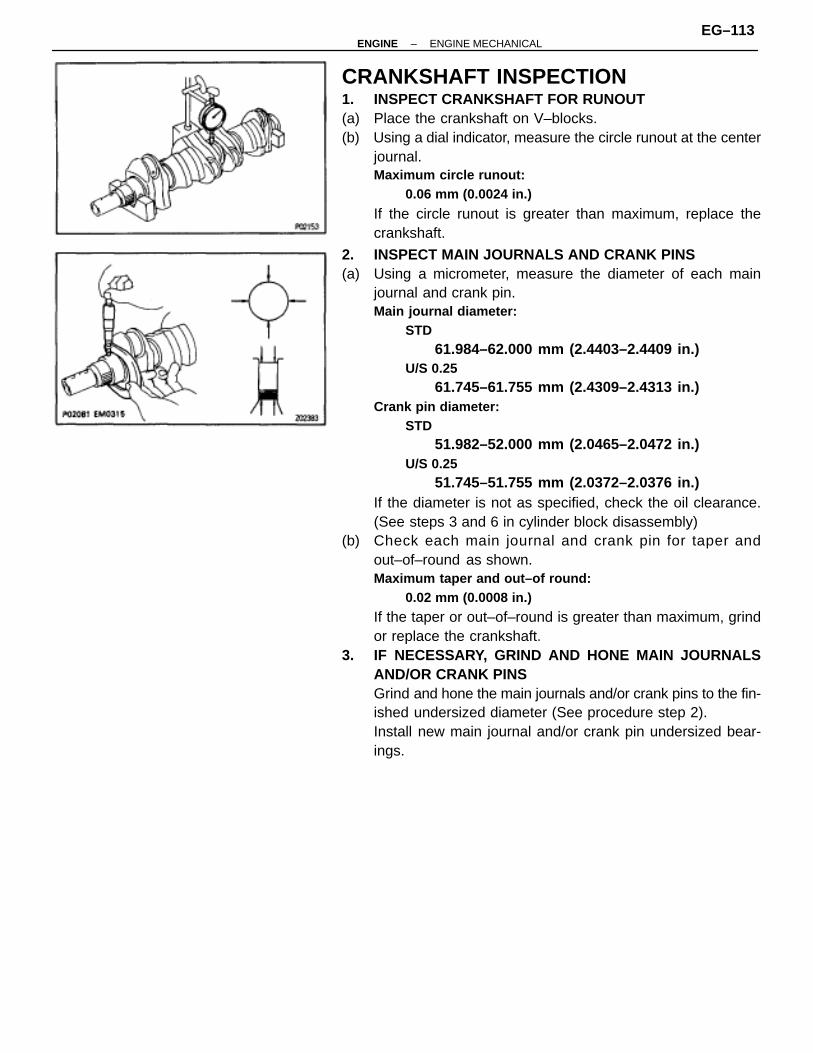
CRANKSHAFT INSPECTION1. INSPECT CRANKSHAFT FOR RUNOUT(a) Place the crankshaft on V–blocks.(b) Using a dial indicator, measure the circle runout at the center
journal.Maximum circle runout:
0.06 mm (0.0024 in.)
If the circle runout is greater than maximum, replace thecrankshaft.
2. INSPECT MAIN JOURNALS AND CRANK PINS(a) Using a micrometer, measure the diameter of each main
journal and crank pin.Main journal diameter:
STD61.984–62.000 mm (2.4403–2.4409 in.)
U/S 0.2561.745–61.755 mm (2.4309–2.4313 in.)
Crank pin diameter:STD
51.982–52.000 mm (2.0465–2.0472 in.)U/S 0.25
51.745–51.755 mm (2.0372–2.0376 in.)If the diameter is not as specified, check the oil clearance.(See steps 3 and 6 in cylinder block disassembly)
(b) Check each main journal and crank pin for taper andout–of–round as shown.Maximum taper and out–of round:
0.02 mm (0.0008 in.)
If the taper or out–of–round is greater than maximum, grindor replace the crankshaft.
3. IF NECESSARY, GRIND AND HONE MAIN JOURNALSAND/OR CRANK PINSGrind and hone the main journals and/or crank pins to the fin-ished undersized diameter (See procedure step 2).Install new main journal and/or crank pin undersized bear-ings.
–ENGINE ENGINE MECHANICALEG–113
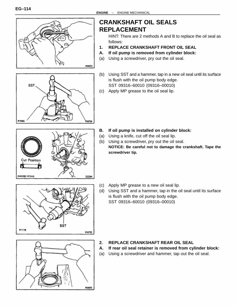
CRANKSHAFT OIL SEALSREPLACEMENT
HINT: There are 2 methods A and B to replace the oil seal asfollows:
1. REPLACE CRANKSHAFT FRONT OIL SEALA. If oil pump is removed from cylinder block:(a) Using a screwdriver, pry out the oil seal.
(b) Using SST and a hammer, tap in a new oil seal until its surfaceis flush with the oil pump body edge.SST 09316–60010 (09316–00010)
(c) Apply MP grease to the oil seal lip.
B. If oil pump is installed on cylinder block:(a) Using a knife, cut off the oil seal lip.(b) Using a screwdriver, pry out the oil seal.
NOTICE: Be careful not to damage the crankshaft. Tape thescrewdriver tip.
(c) Apply MP grease to a new oil seal lip.(d) Using SST and a hammer, tap in the oil seal until its surface
is flush with the oil pump body edge.SST 09316–60010 (09316–00010)
2. REPLACE CRANKSHAFT REAR OIL SEALA. If rear oil seal retainer is removed from cylinder block:(a) Using a screwdriver and hammer, tap out the oil seal.
EG–114–ENGINE ENGINE MECHANICAL
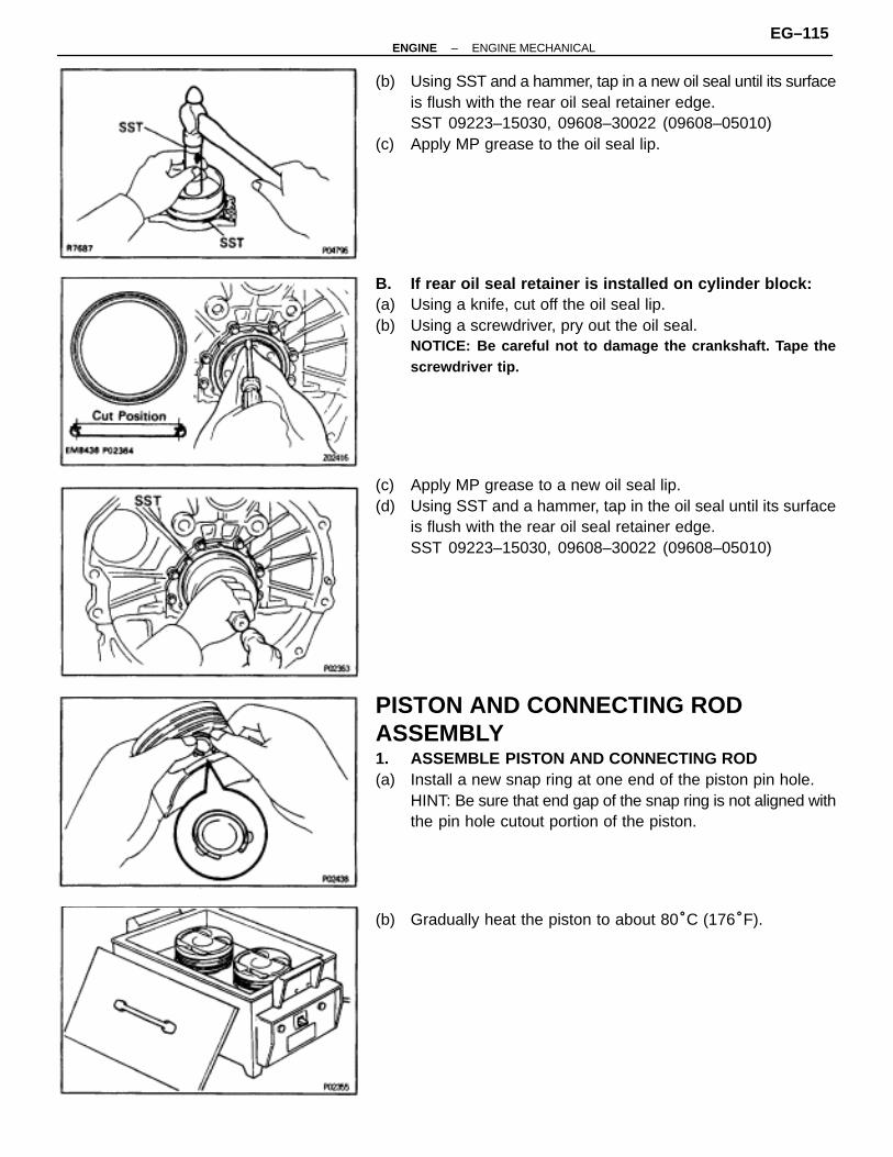
(b) Using SST and a hammer, tap in a new oil seal until its surfaceis flush with the rear oil seal retainer edge.SST 09223–15030, 09608–30022 (09608–05010)
(c) Apply MP grease to the oil seal lip.
B. If rear oil seal retainer is installed on cylinder block:(a) Using a knife, cut off the oil seal lip.(b) Using a screwdriver, pry out the oil seal.
NOTICE: Be careful not to damage the crankshaft. Tape thescrewdriver tip.
(c) Apply MP grease to a new oil seal lip.(d) Using SST and a hammer, tap in the oil seal until its surface
is flush with the rear oil seal retainer edge.SST 09223–15030, 09608–30022 (09608–05010)
PISTON AND CONNECTING RODASSEMBLY1. ASSEMBLE PISTON AND CONNECTING ROD(a) Install a new snap ring at one end of the piston pin hole.
HINT: Be sure that end gap of the snap ring is not aligned withthe pin hole cutout portion of the piston.
(b) Gradually heat the piston to about 80°C (176°F).
–ENGINE ENGINE MECHANICALEG–115

(c) Coat the piston pin with engine oil.(d) Align the front marks of the piston and connecting rod, and
push in the piston pin with your thumb.
(e) Install a new snap ring at the other end of the piston pin hole.HINT: Be sure that end gap of the snap ring is not aligned withthe pin hole cutout portion of the piston.
2. INSTALL PISTON RINGS(a) Install the oil ring expander and 2 side rails by hand.(b) Using a piston ring expander, install the 2 compression rings
with the code mark facing up.Code mark:
2JZ–GENo.1 1TNo.2 2T
2JZ–GTENo.1 1NNo.2 2N
(c) Position the piston rings so that the ring ends are as shown.NOTICE: Do not align the piston ring ends.
3. INSTALL BEARINGS(a) Align the bearing claw with the groove of the connecting rod
and connecting cap.(b) Install the bearings in the connecting rod and connecting rod
cap.
EG–116–ENGINE ENGINE MECHANICAL

CYLINDER BLOCK ASSEMBLYHINT:• Thoroughly clean all parts to be assembled.• Before installing the parts, apply new engine oil to all
sliding and rotating surfaces.• Replace all gaskets, O–rings and oil seals with new
parts.NOTICE: Apply a generous amount of oil on the sliding surfaceof the bearing, and not on the back of it or on the surface towhich it is installed.
1. 2JZ–GTE:INSTALL OIL NOZZLES (WITH RELIEF VALVES)Using a 5 mm hexagon wrench, install the oil nozzle with thebolt. Install the 6 oil nozzles.Torque: 8.8 N ⋅m (90 kgf ⋅cm, 78 in. ⋅lbf)
2. INSTALL MAIN BEARINGSHINT:• Main bearings come in widths of 20.0 mm (0.787 in.) and
23.0 mm (0.906 in.). Install the 23.0 mm bearings in theNo.1 cylinder block journal position with the mainbearing cap. Install the 20.0 mm bearings in the otherpositions.
• Upper bearings have an oil groove and oil holes; lowerbearings do not.
(a) Align the bearing claw with the claw groove of the mainbearing cap or cylinder block.NOTICE: Install the bearing with the oil hole in the cylinderblock.
(b) Install the bearings in the cylinder block and main bearingcaps.
–ENGINE ENGINE MECHANICALEG–117
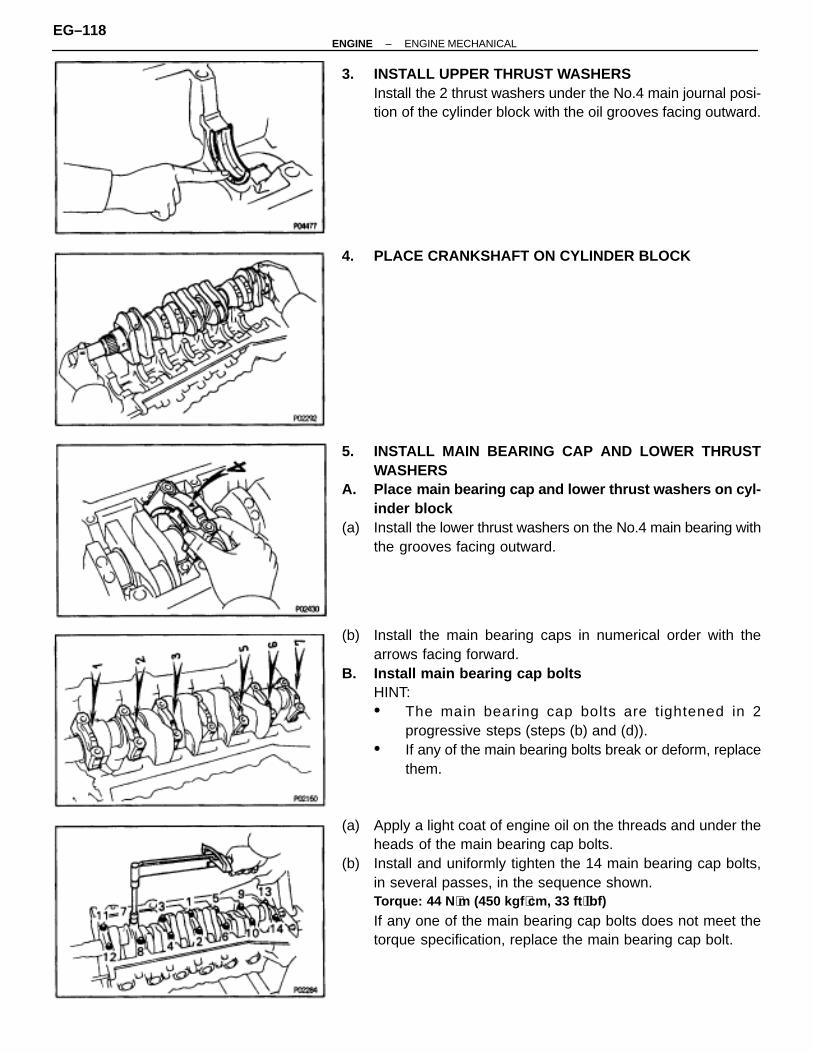
3. INSTALL UPPER THRUST WASHERSInstall the 2 thrust washers under the No.4 main journal posi-tion of the cylinder block with the oil grooves facing outward.
4. PLACE CRANKSHAFT ON CYLINDER BLOCK
5. INSTALL MAIN BEARING CAP AND LOWER THRUSTWASHERS
A. Place main bearing cap and lower thrust washers on cyl-inder block
(a) Install the lower thrust washers on the No.4 main bearing withthe grooves facing outward.
(b) Install the main bearing caps in numerical order with thearrows facing forward.
B. Install main bearing cap boltsHINT:• The main bearing cap bolts are tightened in 2
progressive steps (steps (b) and (d)).• If any of the main bearing bolts break or deform, replace
them.
(a) Apply a light coat of engine oil on the threads and under theheads of the main bearing cap bolts.
(b) Install and uniformly tighten the 14 main bearing cap bolts,in several passes, in the sequence shown.Torque: 44 N ⋅m (450 kgf ⋅cm, 33 ft ⋅lbf)
If any one of the main bearing cap bolts does not meet thetorque specification, replace the main bearing cap bolt.
EG–118–ENGINE ENGINE MECHANICAL

(c) Mark the front of the main bearing cap bolt head with paint.
(d) Retighten the main bearing cap bolts 90° in the numericalorder shown above.
(e) Check that the painted mark is now at a 90° angle to the front.(f) Check that the crankshaft turns smoothly.6. CHECK CRANKSHAFT THRUST CLEARANCE
(See step 5 in cylinder block disassembly)
7. INSTALL PISTON AND CONNECTING ROD ASSEMBLIESUsing a piston ring compressor, push the correctly numberedpiston and connecting rod assemblies into each cylinder withthe front mark of the piston facing forward.
8. INSTALL CONNECTING ROD CAPSA. Place connecting rod cap on connecting rod(a) Match the numbered connecting rod cap with the connecting
rod.(b) Install the connecting rod cap with by aligning the dowel pin
to the corrosponding hole.B. Install connecting rod cap bolts
HINT:• The connecting rod cap bolts are tightened in 2
progressive steps (steps (b) and (d)).
• If any of the connecting rod bolts break or deform,replace them.
(a) Apply a light coat of engine oil on the threads and under theheads of the connecting rod cap bolts.
(b) At first, install and alternately tighten the bolts of theconnecting rod cap in several passes.Torque: 29 N ⋅m (300 kgf ⋅cm, 22 ft ⋅lbf)
If any one of the connecting rod cap bolts does not meet thetorque specification, replace the cap bolt.
–ENGINE ENGINE MECHANICALEG–119

(c) Mark the front of the connecting rod cap bolt with paint.
(d) Retighten the connecting rod cap bolts 90° in the numericalorder shown.
(e) Check that the painted mark is now at a 90° angle to the front.(f) Check that the crankshaft turns smoothly.9. CHECK CONNECTING ROD THRUST CLEARANCE
(See step 2 in cylinder block disassembly)10. INSTALL REAR OIL SEAL RETAINER(a) Remove any old packing (FIPG) material and be careful not
to drop any oil on the contact surfaces of the retainer andcylinder block.• Using a razor blade and gasket scraper, remove all the
old packing (FIPG) material from the gasket surfacesand sealing groove.
• Thoroughly clean all components to remove all debris.• Using a non–residue solvent, clean both sealing
surfaces.
(b) Apply seal packing to the retainer as shown in the illustration.Seal packing:
Part No. 08826–00080 or equivalent
• Install a nozzle that has been cut to a 2–3 mm(0.08–0.12 in.) opening.
• Parts must be assembled within 3 minutes ofapplication. Otherwise the material must be removedand reapplied.
• Immediately remove nozzle from the tube and reinstallcap.
(c) Install the retainer with the 6 bolts.Torque: 5.9 N ⋅m (60 kgf ⋅cm, 52 in. ⋅lbf)
EG–120–ENGINE ENGINE MECHANICAL
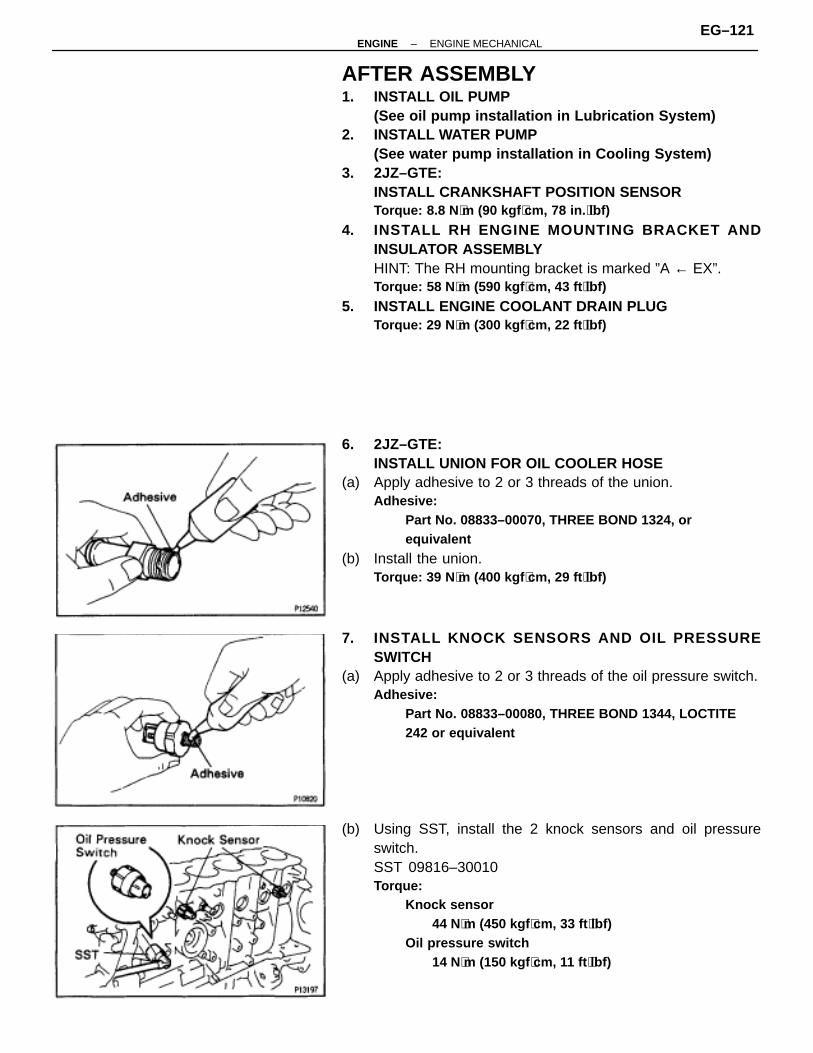
AFTER ASSEMBLY1. INSTALL OIL PUMP
(See oil pump installation in Lubrication System)2. INSTALL WATER PUMP
(See water pump installation in Cooling System)3. 2JZ–GTE:
INSTALL CRANKSHAFT POSITION SENSORTorque: 8.8 N ⋅m (90 kgf ⋅cm, 78 in. ⋅lbf)
4. INSTALL RH ENGINE MOUNTING BRACKET ANDINSULATOR ASSEMBLYHINT: The RH mounting bracket is marked ”A ← EX”.Torque: 58 N ⋅m (590 kgf ⋅cm, 43 ft ⋅lbf)
5. INSTALL ENGINE COOLANT DRAIN PLUGTorque: 29 N ⋅m (300 kgf ⋅cm, 22 ft ⋅lbf)
6. 2JZ–GTE:INSTALL UNION FOR OIL COOLER HOSE
(a) Apply adhesive to 2 or 3 threads of the union.Adhesive:
Part No. 08833–00070, THREE BOND 1324, orequivalent
(b) Install the union.Torque: 39 N ⋅m (400 kgf ⋅cm, 29 ft ⋅lbf)
7. INSTALL KNOCK SENSORS AND OIL PRESSURESWITCH
(a) Apply adhesive to 2 or 3 threads of the oil pressure switch.Adhesive:
Part No. 08833–00080, THREE BOND 1344, LOCTITE242 or equivalent
(b) Using SST, install the 2 knock sensors and oil pressureswitch.SST 09816–30010Torque:
Knock sensor44 N⋅m (450 kgf ⋅cm, 33 ft ⋅lbf)
Oil pressure switch14 N⋅m (150 kgf ⋅cm, 11 ft ⋅lbf)
–ENGINE ENGINE MECHANICALEG–121
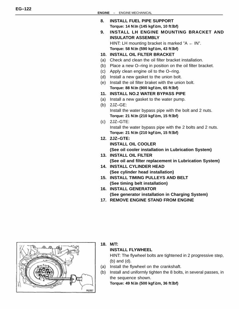
8. INSTALL FUEL PIPE SUPPORTTorque: 14 N ⋅m (145 kgf ⋅cm, 10 ft ⋅lbf)
9. INSTALL LH ENGINE MOUNTING BRACKET ANDINSULATOR ASSEMBLYHINT: LH mounting bracket is marked ”A ← IN”.Torque: 58 N ⋅m (590 kgf ⋅cm, 43 ft ⋅lbf)
10. INSTALL OIL FILTER BRACKET(a) Check and clean the oil filter bracket installation.(b) Place a new O–ring in position on the oil filter bracket.(c) Apply clean engine oil to the O–ring.(d) Install a new gasket to the union bolt.(e) Install the oil filter braket with the union bolt.
Torque: 88 N ⋅m (900 kgf ⋅cm, 65 ft ⋅lbf)
11. INSTALL NO.2 WATER BYPASS PIPE(a) Install a new gasket to the water pump.(b) 2JZ–GE:
Install the water bypass pipe with the bolt and 2 nuts.Torque: 21 N ⋅m (210 kgf ⋅cm, 15 ft ⋅lbf)
(c) 2JZ–GTE:Install the water bypass pipe with the 2 bolts and 2 nuts.Torque: 21 N ⋅m (210 kgf ⋅cm, 15 ft ⋅lbf)
12. 2JZ–GTE:INSTALL OIL COOLER(See oil cooler installation in Lubrication System)
13. INSTALL OIL FILTER(See oil and filter replacement in Lubrication System)
14. INSTALL CYLINDER HEAD(See cylinder head installation)
15. INSTALL TIMING PULLEYS AND BELT(See timing belt installation)
16. INSTALL GENERATOR(See generator installation in Charging System)
17. REMOVE ENGINE STAND FROM ENGINE
18. M/T:INSTALL FLYWHEELHINT: The flywheel bolts are tightened in 2 progressive step,(b) and (d).
(a) Install the flywheel on the crankshaft.(b) Install and uniformly tighten the 8 bolts, in several passes, in
the sequence shown.Torque: 49 N ⋅m (500 kgf ⋅cm, 36 ft ⋅lbf)
EG–122–ENGINE ENGINE MECHANICAL

(c) Mark the flywheel bolt with paint.
(d) Retighten the flywheel bolts by an additional 90°.(e) Check that the painted mark is now at a 90° angle to (d).
19. A/T:INSTALL DRIVE PLATE
(a) Install the front spacer, drive plate and rear plate on thecrankshaft.Adhesive:
Part No. 08833–00070, THREE BOND 1324 or equivalent
(b) Apply adhesive to 2 or 3 threads of the mounting bolt end.
(c) Install and uniformly tighten the 8 bolts, in several passes, inthe sequence shown.Torque: 83 N ⋅m (850 kgf ⋅cm, 61 ft ⋅lbf)
–ENGINE ENGINE MECHANICALEG–123
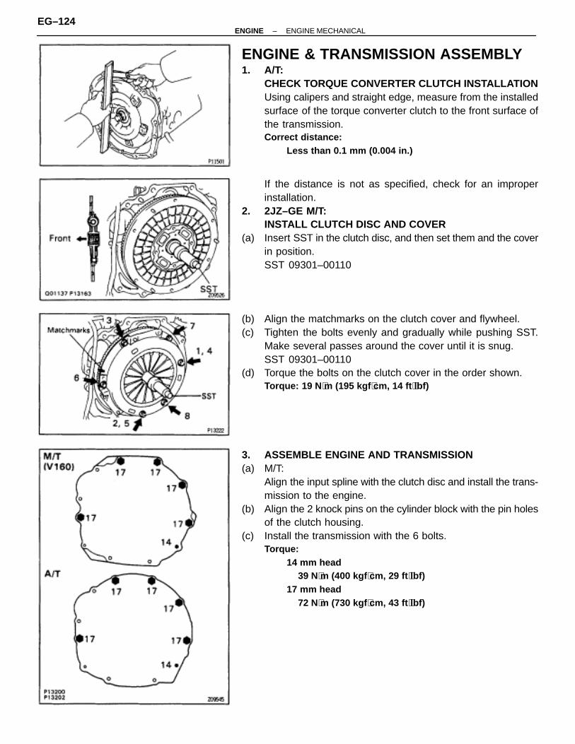
ENGINE & TRANSMISSION ASSEMBLY1. A/T:
CHECK TORQUE CONVERTER CLUTCH INSTALLATIONUsing calipers and straight edge, measure from the installedsurface of the torque converter clutch to the front surface ofthe transmission.Correct distance:
Less than 0.1 mm (0.004 in.)
If the distance is not as specified, check for an improperinstallation.
2. 2JZ–GE M/T:INSTALL CLUTCH DISC AND COVER
(a) Insert SST in the clutch disc, and then set them and the coverin position.SST 09301–00110
(b) Align the matchmarks on the clutch cover and flywheel.(c) Tighten the bolts evenly and gradually while pushing SST.
Make several passes around the cover until it is snug.SST 09301–00110
(d) Torque the bolts on the clutch cover in the order shown.Torque: 19 N ⋅m (195 kgf ⋅cm, 14 ft ⋅lbf)
3. ASSEMBLE ENGINE AND TRANSMISSION(a) M/T:
Align the input spline with the clutch disc and install the trans-mission to the engine.
(b) Align the 2 knock pins on the cylinder block with the pin holesof the clutch housing.
(c) Install the transmission with the 6 bolts.Torque:
14 mm head39 N⋅m (400 kgf ⋅cm, 29 ft ⋅lbf)
17 mm head72 N⋅m (730 kgf ⋅cm, 43 ft ⋅lbf)
EG–124–ENGINE ENGINE MECHANICAL

4. 2JZ–GTE M/T:INSTALL CLUTCH COVER SET BOLTS
(a) Align the matchmarks.(b) Install the 6 bolts while turning the crankshaft to gain access.
Tighten the bolts evenly.Torque: 19 N ⋅m (195 kgf ⋅cm, 14 ft ⋅lbf)
(c) Install the service hole cover with the 2 bolts.Torque: 12 N ⋅m (120 kgf ⋅cm, 9 ft ⋅lbf)
5. A/T:INSTALL TORQUE CONVERTER CLUTCH MOUNTINGBOLTS
(a) First, install the gray bolt. Then install 5 black bolts whileturning the crankshaft to gain access. Tighten the boltsevenly.Torque: 33 N ⋅m (340 kgf ⋅cm, 25 ft ⋅lbf)
(b) Install the hole plug.6. 2JZ–GE A/T:
CONNECT THROTTLE CABLE7. A/T:
INSTALL OIL COOLER TUBES FOR TRANSMISSION(a) Temporarily install the 2 oil cooler tubes, 2 hose clamps and
tube clamp with 3 clamp bolts.(b) Connect the 2 oil cooler tubes to the unions on the
transmission. Tighten the union nuts.Torque: 34 N ⋅m (350 kgf ⋅cm, 25 ft ⋅lbf)
(c) Tighten the 3 clamp bolts.8. INSTALL STARTER9. CONNECT ENGINE WIRE TO TRANSMISSION10. A/T:
INSTALL OIL DIPSTICK GUIDE AND DIPSTICK FORTRANSMISSION
(a) Install a new O–ring to the dipstick guide.(b) Apply soapy water to the O–ring.(c) Connect the dipstick guide end to the dipstick tube of the oil
pan.(d) Install the dipstick guide with the bolt.(e) Install the dipstick.
–ENGINE ENGINE MECHANICALEG–125

ENGINE INSTALLATION (2JZ–GE)1. INSTALL ENGINE AND TRANSMISSION ASSEMBLY IN
VEHICLE(a) Attach the engine hoist chain to the engine hangers.(b) Lower the engine and transmission assembly into the engine
compartment.NOTICE: Install the engine and transmission assembly care-fully without damaging the shift lever retainer (M/ T), A/C com-pressor and PS solenoid valve.
(c) Insert the stud bolts of the front engine mounting insulatorsinto the stud bolt holes of the front suspension crossmember.
(d) Temporarily install the 2 nuts holding the engine frontmounting insulators to the front suspension crossmember.
(e) Keep the engine level with a jack.(f) Remove the hoist chain.
(g) Temporarily install the support member to the engine rearmounting insulator with the 4 nuts.
(h) Install the 4 bolts holding the support member to the body.Torque: 25 N ⋅m (260 kgf ⋅cm, 19 ft ⋅lbf)
(i) Tighten the 4 nuts holding the support member to the enginerear mounting insulator.Torque: 13 N ⋅m (135 kgf ⋅cm, 10 ft ⋅lbf)
(j) Tighten the 2 nuts holding the engine front mountinginsulators to the front suspension crossmember.Torque: 59 N ⋅m (600 kgf ⋅cm, 43 ft ⋅lbf)
2. M/T:INSTALL TRANSMISSION SHIFT LEVERTorque: 19 N ⋅m (195 kgf ⋅cm, 14 ft ⋅lbf)
3. INSTALL PROPELLER SHAFT(See propeller shaft installation in Propeller Shaft)
4. A/T:CONNECT TRANSMISSION CONTROL ROD
(a) Shift the shift lever to N position.(b) Fully turn the control shaft lever back and return 2 notches.
It is now in neutral position.(c) Connect the control rod to the shift lever with the nut.
Torque: 13 N ⋅m (130 kgf ⋅cm, 9 ft ⋅lbf)
EG–126–ENGINE ENGINE MECHANICAL

5. INSTALL EXHAUST PIPE HEAT INSULATOR6. INSTALL NO.2 FRONT EXHAUST PIPE(a) Install 2 new gaskets and the No.2 front exhaust pipe to the
exhaust manifold with 4 new nuts.Torque: 62 N ⋅m (630 kgf ⋅cm, 46 ft ⋅lbf)
(b) Install the pipe support bracket with the 2 bolts.Torque: 43 N ⋅m (440 kgf ⋅cm, 32 ft ⋅lbf)
(c) Install a new gasket and the No.2 front exhaust pipe to thefront exhaust pipe with the 2 bolts and 2 new nuts.Torque: 58 N ⋅m (590 kgf ⋅cm, 43 ft ⋅lbf)
7. M/T:INSTALL CLUTCH RELEASE CYLINDER AND GROUNDSTRAP
(a) Install the clutch release cylinder with the 2 bolts.Torque: 13 N ⋅m (130 kgf ⋅cm, 9 ft ⋅lbf)
(b) Install the ground strap with the bolt.Torque: 37 N ⋅m (380 kgf ⋅cm, 27 ft ⋅lbf)
8. M/T:INSTALL UPPER CONSOLE PANEL, SHIFT LEVERBOOTS AND HOLDING BOLTS
9. CONNECT ENGINE WIRE TO CABIN(a) Push in the engine wire through the cowl panel.
NOTICE: Be careful not to damage the engine wire.
(b) Connect the connector to the connector cassette.(c) Connect the connector to the instrament panel wire
connector.(d) Connect the 2 connectors to the ECM.
(e) Insert the ECM bracket into the stay on the floor panel.(f) Install the ECM with the nut.(g) Install the ECM protector with the 2 nuts.(h) Install the floor carpet.(i) Install the scuff plate.10. CONNECT ENGINE WIRE TO COWL PANEL11. INSTALL A/C COMPRESSOR(a) Using a torx socket (E10), install the stud bolt and
compressor.Torque: 26 N ⋅m (265 kgf ⋅cm, 19 ft ⋅lbf)
(b) Connect the compressor connector.(c) Temporarily install the compessor with the nut and 2 bolts.(d) Alternately tighten the nut and 2 bolts.
Torque: 52 N ⋅m (530 kgf ⋅cm, 38 ft ⋅lbf)
12. INSTALL PS PRESSURE TUBEInstall the pressure tube with the 2 clamp bolts.
–ENGINE ENGINE MECHANICALEG–127

13. INSTALL PS PUMP(a) Install the pump bracket with the 2 bolts.
Torque:A 58 N⋅m (590 kgf ⋅cm, 43 ft ⋅lbf)B 39 N⋅m (400 kgf ⋅cm, 29 ft ⋅lbf)
(b) Install the pump rear stay with the 2 bolts.Torque: 39 N ⋅m (400 kgf ⋅cm, 29 ft ⋅lbf)
(c) Install the pump housing to the pump bracket.(d) Connect the following hoses:
• Air hose to No.4 timing belt cover
• Air hose to air intake chamber(e) Install the front pump bracket with the 2 bolts (A).
Torque: 58 N ⋅m (590 kgf ⋅cm, 43 ft ⋅lbf)
(f) Install the plate washer and bolt (B) to the oil pump.Torque: 52 N ⋅m (530 kgf ⋅cm, 38 ft ⋅lbf)
14. INSTALL ENGINE WIRE BRACKET15. CONNECT FUEL HOSES(a) Connect the fuel return hose to the fuel return pipe.(b) Install the fuel return hose to the clamp of the oil dipstick
guide.(c) Install the fuel inlet hose with 2 new gaskets and the union
bolt.Torque: 29 N ⋅m (300 kgf ⋅cm, 22 ft ⋅lbf)
16. CONNECT WIRES AND CONNECTORS17. CONNECT EVAP HOSE18. CONNECT BRAKE BOOSTER VACUUM HOSE19. CONNECT HEATER HOSES20. INSTALL CHARCOAL CANISTER21. INSTALL WATER PUMP PULLEY, FAN, FLUID COUPLING
ASSEMBLY AND DRIVE BELT(See step 10 in water pump installation in Cooling Sys-tem)
22. INSTALL AIR CLEANER, VAF METER AND INTAKE AIRCONNECTOR PIPE ASSEMBLY
23. CONNECT CONTROL CABLES TO THROTTLE BODY24. FILL WITH FUEL25. FILL WITH ENGINE OIL26. CHECK IGNITION TIMING
(See ignition timing inspection and adjustment)27. INSTALL RADIATOR ASSEMBLY
(See radiator installation in Cooling System)28. START ENGINE AND CHECK FOR LEAKS29. INSTALL HOOD30. ROAD TEST VEHICLE
Check for abnormal noise, shock slippage, correct shiftpoints and smooth operation.
31. RECHECK ENGINE COOLANT AND ENGINE OIL LEVELS
EG–128–ENGINE ENGINE MECHANICAL

ENGINE INSTALLATION (2JZ–GTE)1. INSTALL ENGINE AND TRANSMISSION ASSEMBLY IN
VEHICLE(a) Attach the engine hoist chain to the engine hangers.(b) Lower the engine and transmission assembly into the engine
compartment.NOTICE: Install the engine and transmission assembly care-fully without damaging the shift lever retainer (M/T), A/C com-pressor and PS solenoid valve.
(c) Insert the stud bolts of the front engine mounting insulatorsinto the stud bolt holes of the front suspension crossmember.
(d) Temporarily install the 2 nuts holding the engine frontmounting insulators to the front suspension crossmember.
(e) Keep the engine level with a jack.(f) Remove the hoist chain.
(g) Temporarily install the support member to the engine rearmounting insulator with the 4 nuts.
(h) Install the 4 bolts holding the support member to the body.Torque: 25 N ⋅m (260 kgf ⋅cm, 19 ft ⋅lbf)
(i) Tighten the 4 nuts holding the support member to the enginerear mounting insulator.Torque: 13 N ⋅m (135 kgf ⋅cm, 10 ft ⋅lbf)
(j) Tighten the 2 nuts holding the engine front mountinginsulators to the front suspension crossmember.Torque: 59 N ⋅m (600 kgf ⋅cm, 43 ft ⋅lbf)
2. M/T:INSTALL TRANSMISSION SHIFT LEVERTorque: 19 N ⋅m (195 kgf ⋅cm, 14 ft ⋅lbf)
3. A/T:CONNECT TRANSMISSION CONTROL ROD
(a) Shift the shift lever to N position.(b) Fully turn the control shaft lever back and return 2 notches.
It is now in neutral position.(c) Connect the control rod to the shift lever with the nut.
Torque: 13 N ⋅m (130 kgf ⋅cm, 9 ft ⋅lbf)
4. INSTALL PROPELLER SHAFT(See propeller shaft installation in Propeller Shaft)
–ENGINE ENGINE MECHANICALEG–129

5. INSTALL REAR CENTER FLOOR CROSSMEMBERBRACETorque: 28 N ⋅m (290 kgf ⋅cm, 21 ft ⋅lbf)
6. INSTALL EXHAUST PIPE HEAT INSULATOR7. INSTALL NO.2 FRONT EXHAUST PIPE
Install a new gasket and the front exhaust pipe with 3 newnuts.Torque: 62 N ⋅m (630 kgf ⋅cm, 46 ft ⋅lbf)
8. INSTALL EXHAUST PIPE ASSEMBLY(a) Install the hook of the tailpipe to the 2 rings on the tailpipe
bracket.(b) Install the hook of the exhaust pipe to the 2 rings on the
exhaust pipe brackets.(c) Install the pipe support bracket with the 2 bolts.
Torque: 43 N ⋅m (440 kgf ⋅cm, 32 ft ⋅lbf)
(d) Install a new gasket and the No.2 front exhaust pipe to thefront exhaust pipe with the 2 bolts and 2 new nuts.Torque: 58 N ⋅m (590 kgf ⋅cm, 43 ft ⋅lbf)
9. INSTALL SUB HEATED OXYGEN SENSORInstall a new gasket, the oxygen sensor and sensor coverwith the 2 nuts.Torque: 18 N ⋅m (180 kgf ⋅cm, 13 ft ⋅lbf)
10. M/T:INSTALL CLUTCH RELEASE CYLINDER AND GROUNDSTRAP
(a) Install the clutch release cylinder with the 2 bolts.Torque: 13 N ⋅m (130 kgf ⋅cm, 9 ft ⋅lbf)
(b) Connect the clutch line tube with the bolt.Torque: 37 N ⋅m (380 kgf ⋅cm, 27 ft ⋅lbf)
(c) Install the ground strap with the bolt.Torque: 37 N ⋅m (380 kgf ⋅cm, 27 ft ⋅lbf)
11. CONNECT ENGINE WIRE TO CABIN(a) Push in the engine wire through the cowl panel.
NOTICE: Be careful not to damage the engine wire.
(b) Connect the 2 connectors to the connector cassette.(c) Connect the connector to the instrument panel wire
connector.(d) Connect the 2 connectors to the ECM.(e) Connect the connector to the TRAC ECU.
(f) Insert the ECM bracket into the stay on the floor panel.(g) Install the ECM with the nut.(h) Install the ECM protector with the 2 nuts.(i) Install the floor carpet.(j) Install the scuff plate.12. M/T:
INSTALL UPPER CONSOLE PANEL, SHIFT LEVERBOOTS AND HOLDING BOLTS
EG–130–ENGINE ENGINE MECHANICAL
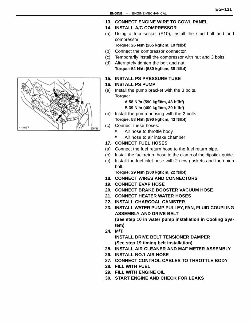
13. CONNECT ENGINE WIRE TO COWL PANEL14. INSTALL A/C COMPRESSOR(a) Using a torx socket (E10), install the stud bolt and and
compressor.Torque: 26 N ⋅m (265 kgf ⋅cm, 19 ft ⋅lbf)
(b) Connect the compressor connector.(c) Temporarily install the compressor with nut and 3 bolts.(d) Alternately tighten the bolt and nut.
Torque: 52 N ⋅m (530 kgf ⋅cm, 38 ft ⋅lbf)
15. INSTALL PS PRESSURE TUBE16. INSTALL PS PUMP(a) Install the pump bracket with the 3 bolts.
Torque:A 58 N⋅m (590 kgf ⋅cm, 43 ft ⋅lbf)B 39 N⋅m (400 kgf ⋅cm, 29 ft ⋅lbf)
(b) Install the pump housing with the 2 bolts.Torque: 58 N ⋅m (590 kgf ⋅cm, 43 ft ⋅lbf)
(c) Connect these hoses:• Air hose to throttle body• Air hose to air intake chamber
17. CONNECT FUEL HOSES(a) Connect the fuel return hose to the fuel return pipe.(b) Install the fuel return hose to the clamp of the dipstick guide.(c) Install the fuel inlet hose with 2 new gaskets and the union
bolt.Torque: 29 N ⋅m (300 kgf ⋅cm, 22 ft ⋅lbf)
18. CONNECT WIRES AND CONNECTORS19. CONNECT EVAP HOSE20. CONNECT BRAKE BOOSTER VACUUM HOSE21. CONNECT HEATER WATER HOSES22. INSTALL CHARCOAL CANISTER23. INSTALL WATER PUMP PULLEY, FAN, FLUID COUPLING
ASSEMBLY AND DRIVE BELT(See step 10 in water pump installation in Cooling Sys-tem)
24. M/T:INSTALL DRIVE BELT TENSIONER DAMPER(See step 19 timing belt installation)
25. INSTALL AIR CLEANER AND MAF METER ASSEMBLY26. INSTALL NO.1 AIR HOSE27. CONNECT CONTROL CABLES TO THROTTLE BODY28. FILL WITH FUEL29. FILL WITH ENGINE OIL30. START ENGINE AND CHECK FOR LEAKS
–ENGINE ENGINE MECHANICALEG–131

31. CHECK IGNITION TIMING(See ignition timing inspection)
32. INSTALL RADIATOR ASSEMBLY(See radiator installation in Cooling System)
33. INSTALL HOOD34. ROAD TEST VEHICLE
Check for abnormal noise, shock slippage, correct shiftpoints and smooth operation.
35. RECHECK ENGINE COOLANT AND ENGINE OIL LEVELS
EG–132–ENGINE ENGINE MECHANICAL

EXHAUST SYSTEMCOMPONENTS
–ENGINE ENGINE MECHANICALEG–133
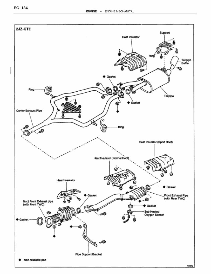
EG–134–ENGINE ENGINE MECHANICAL

SERVICE SPECIFICATIONSSERVICE DATAÑÑÑÑÑÑÑÑÑÑÑÑÑÑÑÑÑÑÑÑÑÑÑÑÑÑÑÑÑÑÑÑÑÑÑÑ
Compressionpressure
ÑÑÑÑÑÑÑÑÑÑÑÑÑÑÑÑÑÑÑÑÑÑÑÑÑÑÑÑÑÑÑÑÑÑÑÑÑÑÑÑÑÑÑÑÑÑÑÑÑÑÑÑÑÑÑÑÑÑÑÑÑÑÑÑÑÑÑÑÑÑÑÑÑÑÑÑÑÑÑÑÑÑÑÑÑÑÑÑÑÑÑÑÑÑÑÑ
at 250 rpm STD 2JZ–GE2JZ–GTE
Minimum 2JZ–GE2JZ–GTE
Difference of pressure between each cylinder
ÑÑÑÑÑÑÑÑÑÑÑÑÑÑÑÑÑÑÑÑÑÑÑÑÑÑÑÑÑÑÑÑÑÑÑÑÑÑÑÑÑÑÑÑÑÑÑÑÑÑÑÑÑÑÑÑÑÑÑÑÑÑÑÑÑÑÑÑÑÑÑÑÑÑÑÑÑÑÑÑÑÑÑÑÑÑÑÑÑÑÑÑÑÑÑÑ
1,275 kPa (13.0 kgf/cm2, 185 psi) or more1,079 kPa (11.0 kgf/cm2, 156 psi) or more1,079 kPa (11.0 kgf/cm2, 156 psi)883 kPa (9.0 kgf/cm2, 128 psi)98 kPa (1.0 kgf/cm2, 14 psi) or less
ÑÑÑÑÑÑÑÑÑÑÑÑÑÑÑÑÑÑÑÑÑÑÑÑÑÑÑÑÑÑÑÑÑÑÑÑÑÑÑÑÑÑÑÑÑÑÑÑÑÑÑÑÑÑÑÑÑÑÑÑÑÑÑÑÑÑÑÑÑÑÑÑÑÑÑÑÑÑÑÑÑÑÑÑÑÑÑÑÑÑÑÑÑÑÑÑÑÑÑÑÑÑÑÑÑÑÑÑ
Valveclearance
ÑÑÑÑÑÑÑÑÑÑÑÑÑÑÑÑÑÑÑÑÑÑÑÑÑÑÑÑÑÑÑÑÑÑÑÑÑÑÑÑÑÑÑÑÑÑÑÑÑÑÑÑÑÑÑÑÑÑÑÑÑÑÑÑÑÑÑÑÑÑÑÑÑÑÑÑÑÑÑÑÑÑÑÑÑÑÑÑÑÑÑÑÑÑÑÑÑÑÑÑÑÑÑÑÑÑÑÑÑÑÑÑÑÑÑÑÑÑÑÑÑÑÑÑÑÑÑÑÑÑÑÑÑÑÑÑÑÑÑÑÑÑÑÑÑÑÑÑÑÑÑÑÑÑÑÑÑÑÑÑÑÑÑÑÑÑÑÑÑÑÑÑÑÑÑÑÑÑÑÑÑÑÑÑÑÑÑÑÑÑÑÑÑÑÑÑÑÑÑÑÑÑÑÑÑÑÑÑÑÑÑÑÑÑÑÑÑÑÑÑÑÑÑÑÑÑÑÑÑÑÑÑÑÑÑÑÑÑÑÑÑÑÑÑÑÑÑÑÑÑÑÑÑÑÑÑÑÑÑÑÑÑÑÑÑÑÑÑÑÑÑÑÑÑÑÑÑÑÑÑÑÑÑÑÑÑÑÑ
at cold IntakeExhaust
Adjusting shim (for repair part) Mark 2500Mark 2.550Mark 2.600Mark 2.650Mark 2.700Mark 2.750Mark 2.800Mark 2.850Mark 2.900Mark 2.950Mark 3.000Mark 3.050Mark 3.100Mark 3.150Mark 3.200Mark 3.250Mark 3.300
ÑÑÑÑÑÑÑÑÑÑÑÑÑÑÑÑÑÑÑÑÑÑÑÑÑÑÑÑÑÑÑÑÑÑÑÑÑÑÑÑÑÑÑÑÑÑÑÑÑÑÑÑÑÑÑÑÑÑÑÑÑÑÑÑÑÑÑÑÑÑÑÑÑÑÑÑÑÑÑÑÑÑÑÑÑÑÑÑÑÑÑÑÑÑÑÑÑÑÑÑÑÑÑÑÑÑÑÑÑÑÑÑÑÑÑÑÑÑÑÑÑÑÑÑÑÑÑÑÑÑÑÑÑÑÑÑÑÑÑÑÑÑÑÑÑÑÑÑÑÑÑÑÑÑÑÑÑÑÑÑÑÑÑÑÑÑÑÑÑÑÑÑÑÑÑÑÑÑÑÑÑÑÑÑÑÑÑÑÑÑÑÑÑÑÑÑÑÑÑÑÑÑÑÑÑÑÑÑÑÑÑÑÑÑÑÑÑÑÑÑÑÑÑÑÑÑÑÑÑÑÑÑÑÑÑÑÑÑÑÑÑÑÑÑÑÑÑÑÑÑÑÑÑÑÑÑÑÑÑÑÑÑÑÑÑÑÑÑÑÑÑÑÑÑÑÑÑÑÑÑÑÑÑÑÑÑÑÑ
0.15–0.25 mm (0.006–0.010 in.)0.25–0.35 mm (0.010–0.014 in.)2.500 mm (0.0984 in.)2.550 mm (0.1004 in.)2.600 mm (0.1024 in.)2.650 mm (0.1043 in.)2.700 mm (0.1063 in.)2.750 mm (0.1083 in.)2.800 mm (0.1102 in.)2.850 mm (0.1122 in.)2.900 mm (0.1142 in.)2.950 mm (0.1161 in.)3.000 mm (0.1181 in.)3.050 mm (0.1201 in.)3.100 mm (0.1220 in.)3.150 mm (0.1240 in.)3.200 mm (0.1260 in.)3.250 mm (0.1280 in.)3.300 mm (0.1299 in.)
ÑÑÑÑÑÑÑÑÑÑÑÑ
Ignition timingÑÑÑÑÑÑÑÑÑÑÑÑÑÑÑÑÑÑÑÑÑÑÑÑÑÑÑÑÑÑÑÑ
w/ Terminals TE1 and E1 connected of DLC1ÑÑÑÑÑÑÑÑÑÑÑÑÑÑÑÑÑÑÑÑÑÑÑÑÑÑÑÑÑÑÑÑ
10° BTDC @ idleÑÑÑÑÑÑÑÑÑÑÑÑÑÑÑÑÑÑ
Idle speed ÑÑÑÑÑÑÑÑÑÑÑÑÑÑÑÑÑÑÑÑÑÑÑÑÑÑÑÑÑÑÑÑÑÑÑÑÑÑÑÑÑÑÑÑÑÑÑÑ
2JZ–GE2JZ–GTE
ÑÑÑÑÑÑÑÑÑÑÑÑÑÑÑÑÑÑÑÑÑÑÑÑÑÑÑÑÑÑÑÑÑÑÑÑÑÑÑÑÑÑÑÑÑÑÑÑ
700 ± 50 rpm650 ± 50 rpm
ÑÑÑÑÑÑÑÑÑÑÑÑÑÑÑÑÑÑÑÑÑÑÑÑ
IntakeManifoldVacuum
ÑÑÑÑÑÑÑÑÑÑÑÑÑÑÑÑÑÑÑÑÑÑÑÑÑÑÑÑÑÑÑÑÑÑÑÑÑÑÑÑÑÑÑÑÑÑÑÑÑÑÑÑÑÑÑÑÑÑÑÑÑÑÑÑ
at idle speed 2JZ–GE2JZ–GTE
ÑÑÑÑÑÑÑÑÑÑÑÑÑÑÑÑÑÑÑÑÑÑÑÑÑÑÑÑÑÑÑÑÑÑÑÑÑÑÑÑÑÑÑÑÑÑÑÑÑÑÑÑÑÑÑÑÑÑÑÑÑÑÑÑ
66.6 kPa (500 mmHg, 19.7 in.Hg) or more60 kPa (450 mmHg, 17.7 in.Hg) or more
ÑÑÑÑÑÑÑÑÑÑÑÑÑÑÑÑÑÑ
Timing beltTensioner
ÑÑÑÑÑÑÑÑÑÑÑÑÑÑÑÑÑÑÑÑÑÑÑÑÑÑÑÑÑÑÑÑÑÑÑÑÑÑÑÑÑÑÑÑÑÑÑÑ
Protrusion (from housing side)ÑÑÑÑÑÑÑÑÑÑÑÑÑÑÑÑÑÑÑÑÑÑÑÑÑÑÑÑÑÑÑÑÑÑÑÑÑÑÑÑÑÑÑÑÑÑÑÑ
8.0–8.8 mm (0.315–0.346 in.)
ÑÑÑÑÑÑÑÑÑÑÑÑÑÑÑÑÑÑÑÑÑÑÑÑÑÑÑÑÑÑÑÑÑÑÑÑÑÑÑÑÑÑÑÑÑÑÑÑÑÑÑÑÑÑÑÑÑÑÑÑÑÑÑÑÑÑÑÑÑÑÑÑÑÑÑÑÑÑ
Cylinder headÑÑÑÑÑÑÑÑÑÑÑÑÑÑÑÑÑÑÑÑÑÑÑÑÑÑÑÑÑÑÑÑÑÑÑÑÑÑÑÑÑÑÑÑÑÑÑÑÑÑÑÑÑÑÑÑÑÑÑÑÑÑÑÑÑÑÑÑÑÑÑÑÑÑÑÑÑÑÑÑÑÑÑÑÑÑÑÑÑÑÑÑÑÑÑÑÑÑÑÑÑÑÑÑÑÑÑÑÑÑÑÑÑÑÑÑÑÑÑÑÑÑÑÑÑÑÑÑÑÑÑÑÑÑÑÑÑÑÑÑÑÑÑÑÑÑÑÑÑÑÑÑÑÑÑÑÑÑÑÑÑÑÑÑÑÑÑÑÑÑÑÑÑÑÑÑÑÑÑÑÑÑÑÑÑÑÑÑÑÑÑÑÑÑÑÑÑÑÑÑÑÑÑÑÑÑÑÑ
WarpageCylinder block side MaximumIntake manifold side MaximumExhaust manifold side Maximum
Valve guide bore diameter STDO/S 0.05
Valve seatRefacing angleContacting angleContacting width Intake
ExhaustCylinder head bolt diameter STD
Minimum
ÑÑÑÑÑÑÑÑÑÑÑÑÑÑÑÑÑÑÑÑÑÑÑÑÑÑÑÑÑÑÑÑÑÑÑÑÑÑÑÑÑÑÑÑÑÑÑÑÑÑÑÑÑÑÑÑÑÑÑÑÑÑÑÑÑÑÑÑÑÑÑÑÑÑÑÑÑÑÑÑÑÑÑÑÑÑÑÑÑÑÑÑÑÑÑÑÑÑÑÑÑÑÑÑÑÑÑÑÑÑÑÑÑÑÑÑÑÑÑÑÑÑÑÑÑÑÑÑÑÑÑÑÑÑÑÑÑÑÑÑÑÑÑÑÑÑÑÑÑÑÑÑÑÑÑÑÑÑÑÑÑÑÑÑÑÑÑÑÑÑÑÑÑÑÑÑÑÑÑÑÑÑÑÑÑÑÑÑÑÑÑÑÑÑÑÑÑÑÑÑÑÑÑÑÑÑÑÑ
0.10 mm (0.0039 in.)0.10 mm (0.0039 in.)0.10 mm (0.0039 in.)10.985–11.006 mm (0.4325–0.4333 in.)11.035–11.056 mm (0.4344–0.4353 in.)
15°, 45°, 60°45°1.0–1.4 mm (0.039–0.055 in.)1.2–1.6 mm (0.047–0.063 in.)10.8–11.0 mm (0.425–0.433 in.)10.7 mm (0.421 in.)
–ENGINE ENGINE MECHANICALEG–135
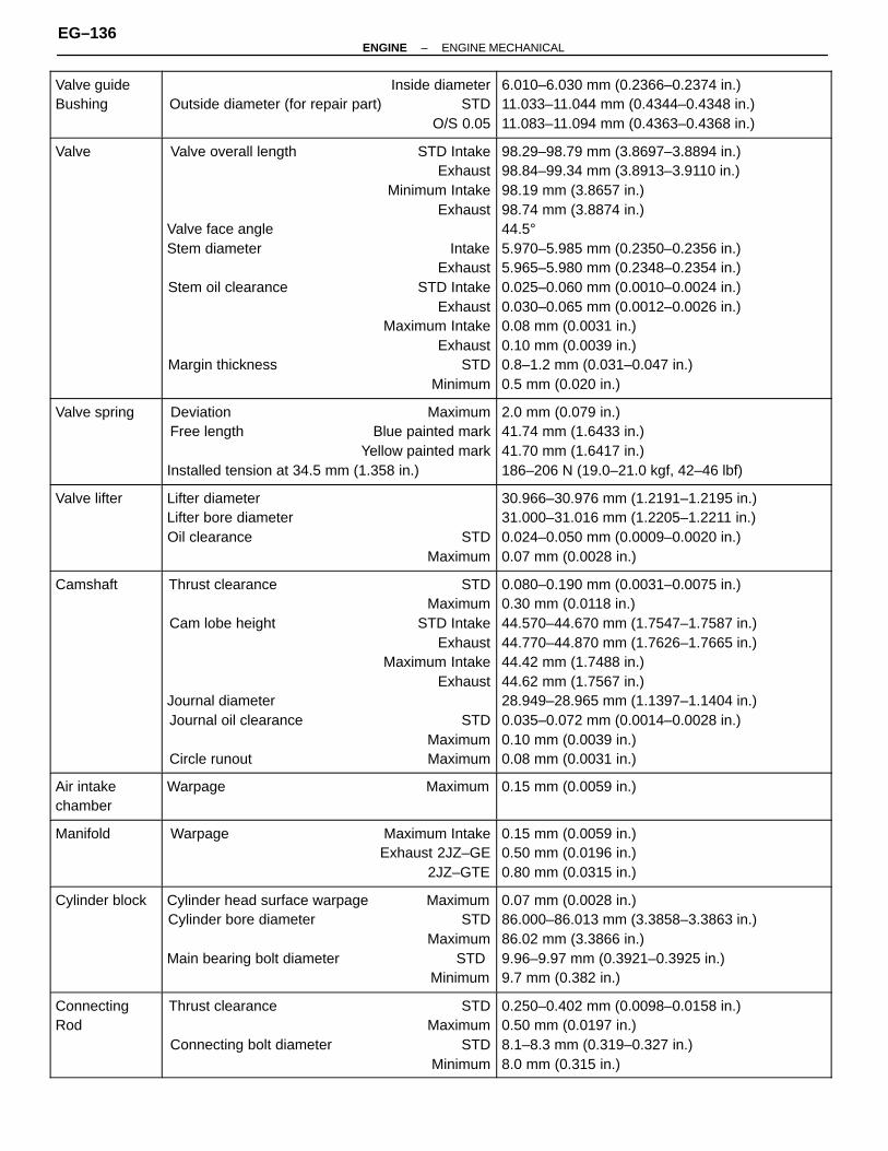
ÑÑÑÑÑÑÑÑÑÑÑÑÑÑÑÑÑÑÑÑÑÑÑÑ
Valve guideBushing
ÑÑÑÑÑÑÑÑÑÑÑÑÑÑÑÑÑÑÑÑÑÑÑÑÑÑÑÑÑÑÑÑÑÑÑÑÑÑÑÑÑÑÑÑÑÑÑÑÑÑÑÑÑÑÑÑÑÑÑÑÑÑÑÑ
Inside diameterOutside diameter (for repair part) STD
O/S 0.05
ÑÑÑÑÑÑÑÑÑÑÑÑÑÑÑÑÑÑÑÑÑÑÑÑÑÑÑÑÑÑÑÑÑÑÑÑÑÑÑÑÑÑÑÑÑÑÑÑÑÑÑÑÑÑÑÑÑÑÑÑÑÑÑÑ
6.010–6.030 mm (0.2366–0.2374 in.)11.033–11.044 mm (0.4344–0.4348 in.)11.083–11.094 mm (0.4363–0.4368 in.)
ÑÑÑÑÑÑÑÑÑÑÑÑÑÑÑÑÑÑÑÑÑÑÑÑÑÑÑÑÑÑÑÑÑÑÑÑÑÑÑÑÑÑÑÑÑÑÑÑÑÑÑÑÑÑÑÑÑÑÑÑÑÑÑÑÑÑÑÑÑÑÑÑ
Valve ÑÑÑÑÑÑÑÑÑÑÑÑÑÑÑÑÑÑÑÑÑÑÑÑÑÑÑÑÑÑÑÑÑÑÑÑÑÑÑÑÑÑÑÑÑÑÑÑÑÑÑÑÑÑÑÑÑÑÑÑÑÑÑÑÑÑÑÑÑÑÑÑÑÑÑÑÑÑÑÑÑÑÑÑÑÑÑÑÑÑÑÑÑÑÑÑÑÑÑÑÑÑÑÑÑÑÑÑÑÑÑÑÑÑÑÑÑÑÑÑÑÑÑÑÑÑÑÑÑÑÑÑÑÑÑÑÑÑÑÑÑÑÑÑÑÑÑÑÑÑÑÑÑÑÑÑÑÑÑÑÑÑÑÑÑÑÑÑÑÑÑÑÑÑÑÑÑÑÑÑÑÑÑÑÑÑÑÑÑÑÑÑ
Valve overall length STD IntakeExhaust
Minimum IntakeExhaust
Valve face angleStem diameter Intake
ExhaustStem oil clearance STD Intake
ExhaustMaximum Intake
ExhaustMargin thickness STD
Minimum
ÑÑÑÑÑÑÑÑÑÑÑÑÑÑÑÑÑÑÑÑÑÑÑÑÑÑÑÑÑÑÑÑÑÑÑÑÑÑÑÑÑÑÑÑÑÑÑÑÑÑÑÑÑÑÑÑÑÑÑÑÑÑÑÑÑÑÑÑÑÑÑÑÑÑÑÑÑÑÑÑÑÑÑÑÑÑÑÑÑÑÑÑÑÑÑÑÑÑÑÑÑÑÑÑÑÑÑÑÑÑÑÑÑÑÑÑÑÑÑÑÑÑÑÑÑÑÑÑÑÑÑÑÑÑÑÑÑÑÑÑÑÑÑÑÑÑÑÑÑÑÑÑÑÑÑÑÑÑÑÑÑÑÑÑÑÑÑÑÑÑÑÑÑÑÑÑÑÑÑÑÑÑÑÑÑÑÑÑÑÑÑÑ
98.29–98.79 mm (3.8697–3.8894 in.)98.84–99.34 mm (3.8913–3.9110 in.)98.19 mm (3.8657 in.)98.74 mm (3.8874 in.)44.5°5.970–5.985 mm (0.2350–0.2356 in.)5.965–5.980 mm (0.2348–0.2354 in.)0.025–0.060 mm (0.0010–0.0024 in.)0.030–0.065 mm (0.0012–0.0026 in.)0.08 mm (0.0031 in.)0.10 mm (0.0039 in.)0.8–1.2 mm (0.031–0.047 in.)0.5 mm (0.020 in.)
ÑÑÑÑÑÑÑÑÑÑÑÑÑÑÑÑÑÑÑÑÑÑÑÑÑÑÑÑÑÑ
Valve springÑÑÑÑÑÑÑÑÑÑÑÑÑÑÑÑÑÑÑÑÑÑÑÑÑÑÑÑÑÑÑÑÑÑÑÑÑÑÑÑÑÑÑÑÑÑÑÑÑÑÑÑÑÑÑÑÑÑÑÑÑÑÑÑÑÑÑÑÑÑÑÑÑÑÑÑÑÑÑÑ
Deviation MaximumFree length Blue painted mark
Yellow painted markInstalled tension at 34.5 mm (1.358 in.)
ÑÑÑÑÑÑÑÑÑÑÑÑÑÑÑÑÑÑÑÑÑÑÑÑÑÑÑÑÑÑÑÑÑÑÑÑÑÑÑÑÑÑÑÑÑÑÑÑÑÑÑÑÑÑÑÑÑÑÑÑÑÑÑÑÑÑÑÑÑÑÑÑÑÑÑÑÑÑÑÑ
2.0 mm (0.079 in.)41.74 mm (1.6433 in.)41.70 mm (1.6417 in.)186–206 N (19.0–21.0 kgf, 42–46 lbf)
ÑÑÑÑÑÑÑÑÑÑÑÑÑÑÑÑÑÑÑÑÑÑÑÑÑÑÑÑÑÑ
Valve lifterÑÑÑÑÑÑÑÑÑÑÑÑÑÑÑÑÑÑÑÑÑÑÑÑÑÑÑÑÑÑÑÑÑÑÑÑÑÑÑÑÑÑÑÑÑÑÑÑÑÑÑÑÑÑÑÑÑÑÑÑÑÑÑÑÑÑÑÑÑÑÑÑÑÑÑÑÑÑÑÑ
Lifter diameterLifter bore diameterOil clearance STD
Maximum
ÑÑÑÑÑÑÑÑÑÑÑÑÑÑÑÑÑÑÑÑÑÑÑÑÑÑÑÑÑÑÑÑÑÑÑÑÑÑÑÑÑÑÑÑÑÑÑÑÑÑÑÑÑÑÑÑÑÑÑÑÑÑÑÑÑÑÑÑÑÑÑÑÑÑÑÑÑÑÑÑ
30.966–30.976 mm (1.2191–1.2195 in.)31.000–31.016 mm (1.2205–1.2211 in.)0.024–0.050 mm (0.0009–0.0020 in.)0.07 mm (0.0028 in.)
ÑÑÑÑÑÑÑÑÑÑÑÑÑÑÑÑÑÑÑÑÑÑÑÑÑÑÑÑÑÑÑÑÑÑÑÑÑÑÑÑÑÑÑÑÑÑÑÑÑÑÑÑÑÑÑÑÑÑÑÑ
CamshaftÑÑÑÑÑÑÑÑÑÑÑÑÑÑÑÑÑÑÑÑÑÑÑÑÑÑÑÑÑÑÑÑÑÑÑÑÑÑÑÑÑÑÑÑÑÑÑÑÑÑÑÑÑÑÑÑÑÑÑÑÑÑÑÑÑÑÑÑÑÑÑÑÑÑÑÑÑÑÑÑÑÑÑÑÑÑÑÑÑÑÑÑÑÑÑÑÑÑÑÑÑÑÑÑÑÑÑÑÑÑÑÑÑÑÑÑÑÑÑÑÑÑÑÑÑÑÑÑÑÑÑÑÑÑÑÑÑÑÑÑÑÑÑÑÑÑÑÑÑÑÑÑÑÑÑÑÑÑÑÑ
Thrust clearance STDMaximum
Cam lobe height STD IntakeExhaust
Maximum IntakeExhaust
Journal diameterJournal oil clearance STD
MaximumCircle runout Maximum
ÑÑÑÑÑÑÑÑÑÑÑÑÑÑÑÑÑÑÑÑÑÑÑÑÑÑÑÑÑÑÑÑÑÑÑÑÑÑÑÑÑÑÑÑÑÑÑÑÑÑÑÑÑÑÑÑÑÑÑÑÑÑÑÑÑÑÑÑÑÑÑÑÑÑÑÑÑÑÑÑÑÑÑÑÑÑÑÑÑÑÑÑÑÑÑÑÑÑÑÑÑÑÑÑÑÑÑÑÑÑÑÑÑÑÑÑÑÑÑÑÑÑÑÑÑÑÑÑÑÑÑÑÑÑÑÑÑÑÑÑÑÑÑÑÑÑÑÑÑÑÑÑÑÑÑÑÑÑÑÑ
0.080–0.190 mm (0.0031–0.0075 in.)0.30 mm (0.0118 in.)44.570–44.670 mm (1.7547–1.7587 in.)44.770–44.870 mm (1.7626–1.7665 in.)44.42 mm (1.7488 in.)44.62 mm (1.7567 in.)28.949–28.965 mm (1.1397–1.1404 in.)0.035–0.072 mm (0.0014–0.0028 in.)0.10 mm (0.0039 in.)0.08 mm (0.0031 in.)
ÑÑÑÑÑÑÑÑÑÑÑÑÑÑÑÑÑÑ
Air intakechamber
ÑÑÑÑÑÑÑÑÑÑÑÑÑÑÑÑÑÑÑÑÑÑÑÑÑÑÑÑÑÑÑÑÑÑÑÑÑÑÑÑÑÑÑÑÑÑÑÑ
Warpage MaximumÑÑÑÑÑÑÑÑÑÑÑÑÑÑÑÑÑÑÑÑÑÑÑÑÑÑÑÑÑÑÑÑÑÑÑÑÑÑÑÑÑÑÑÑÑÑÑÑ
0.15 mm (0.0059 in.)
ÑÑÑÑÑÑÑÑÑÑÑÑÑÑÑÑÑÑÑÑÑÑÑÑ
ManifoldÑÑÑÑÑÑÑÑÑÑÑÑÑÑÑÑÑÑÑÑÑÑÑÑÑÑÑÑÑÑÑÑÑÑÑÑÑÑÑÑÑÑÑÑÑÑÑÑÑÑÑÑÑÑÑÑÑÑÑÑÑÑÑÑ
Warpage Maximum IntakeExhaust 2JZ–GE
2JZ–GTE
ÑÑÑÑÑÑÑÑÑÑÑÑÑÑÑÑÑÑÑÑÑÑÑÑÑÑÑÑÑÑÑÑÑÑÑÑÑÑÑÑÑÑÑÑÑÑÑÑÑÑÑÑÑÑÑÑÑÑÑÑÑÑÑÑ
0.15 mm (0.0059 in.)0.50 mm (0.0196 in.)0.80 mm (0.0315 in.)
ÑÑÑÑÑÑÑÑÑÑÑÑÑÑÑÑÑÑÑÑÑÑÑÑÑÑÑÑÑÑÑÑÑÑÑÑ
Cylinder blockÑÑÑÑÑÑÑÑÑÑÑÑÑÑÑÑÑÑÑÑÑÑÑÑÑÑÑÑÑÑÑÑÑÑÑÑÑÑÑÑÑÑÑÑÑÑÑÑÑÑÑÑÑÑÑÑÑÑÑÑÑÑÑÑÑÑÑÑÑÑÑÑÑÑÑÑÑÑÑÑÑÑÑÑÑÑÑÑÑÑÑÑÑÑÑÑ
Cylinder head surface warpage MaximumCylinder bore diameter STD
MaximumMain bearing bolt diameter STD Minimum
ÑÑÑÑÑÑÑÑÑÑÑÑÑÑÑÑÑÑÑÑÑÑÑÑÑÑÑÑÑÑÑÑÑÑÑÑÑÑÑÑÑÑÑÑÑÑÑÑÑÑÑÑÑÑÑÑÑÑÑÑÑÑÑÑÑÑÑÑÑÑÑÑÑÑÑÑÑÑÑÑÑÑÑÑÑÑÑÑÑÑÑÑÑÑÑÑ
0.07 mm (0.0028 in.)86.000–86.013 mm (3.3858–3.3863 in.)86.02 mm (3.3866 in.)9.96–9.97 mm (0.3921–0.3925 in.)9.7 mm (0.382 in.)
ÑÑÑÑÑÑÑÑÑÑÑÑÑÑÑÑÑÑÑÑÑÑÑÑÑÑÑÑÑÑ
ConnectingRod
ÑÑÑÑÑÑÑÑÑÑÑÑÑÑÑÑÑÑÑÑÑÑÑÑÑÑÑÑÑÑÑÑÑÑÑÑÑÑÑÑÑÑÑÑÑÑÑÑÑÑÑÑÑÑÑÑÑÑÑÑÑÑÑÑÑÑÑÑÑÑÑÑÑÑÑÑÑÑÑÑ
Thrust clearance STDMaximum
Connecting bolt diameter STDMinimum
ÑÑÑÑÑÑÑÑÑÑÑÑÑÑÑÑÑÑÑÑÑÑÑÑÑÑÑÑÑÑÑÑÑÑÑÑÑÑÑÑÑÑÑÑÑÑÑÑÑÑÑÑÑÑÑÑÑÑÑÑÑÑÑÑÑÑÑÑÑÑÑÑÑÑÑÑÑÑÑÑ
0.250–0.402 mm (0.0098–0.0158 in.)0.50 mm (0.0197 in.)8.1–8.3 mm (0.319–0.327 in.)8.0 mm (0.315 in.)
EG–136–ENGINE ENGINE MECHANICAL

ÑÑÑÑÑÑÑÑÑÑÑÑÑÑÑÑÑÑÑÑÑÑÑÑÑÑÑÑÑÑÑÑÑÑÑÑÑÑÑÑÑÑÑÑÑÑÑÑÑÑÑÑÑÑÑÑÑÑÑÑÑÑÑÑÑÑÑÑÑÑÑÑÑÑÑÑÑÑÑÑÑÑÑÑÑÑÑÑÑÑ
Connectingrod (cont’d)
ÑÑÑÑÑÑÑÑÑÑÑÑÑÑÑÑÑÑÑÑÑÑÑÑÑÑÑÑÑÑÑÑÑÑÑÑÑÑÑÑÑÑÑÑÑÑÑÑÑÑÑÑÑÑÑÑÑÑÑÑÑÑÑÑÑÑÑÑÑÑÑÑÑÑÑÑÑÑÑÑÑÑÑÑÑÑÑÑÑÑÑÑÑÑÑÑÑÑÑÑÑÑÑÑÑÑÑÑÑÑÑÑÑÑÑÑÑÑÑÑÑÑÑÑÑÑÑÑÑÑÑÑÑÑÑÑÑÑÑÑÑÑÑÑÑÑÑÑÑÑÑÑÑÑÑÑÑÑÑÑÑÑÑÑÑÑÑÑÑÑÑÑÑÑÑÑÑÑÑÑÑÑÑÑÑÑÑÑÑÑÑÑÑÑÑÑÑÑÑÑÑÑÑÑÑÑÑÑÑÑÑÑÑÑÑÑÑÑÑÑÑÑÑÑÑÑÑÑÑÑÑÑÑÑÑÑÑÑÑÑ
Connecting rod oil clearance STD STDU/S 0.25
Maximum STDU/S 0.25
Connecting rod bearing center wall thickness (Reference) STD Mark 1
Mark 2Mark 3Mark 4Mark 5
Bushing inside diameterPiston pin diameterPiston pin oil clearance STD
MaximumRod bent Maximum per 100 mm (3.94 in.)Rod twist Maximum per 100 mm (3.94 in.)
ÑÑÑÑÑÑÑÑÑÑÑÑÑÑÑÑÑÑÑÑÑÑÑÑÑÑÑÑÑÑÑÑÑÑÑÑÑÑÑÑÑÑÑÑÑÑÑÑÑÑÑÑÑÑÑÑÑÑÑÑÑÑÑÑÑÑÑÑÑÑÑÑÑÑÑÑÑÑÑÑÑÑÑÑÑÑÑÑÑÑÑÑÑÑÑÑÑÑÑÑÑÑÑÑÑÑÑÑÑÑÑÑÑÑÑÑÑÑÑÑÑÑÑÑÑÑÑÑÑÑÑÑÑÑÑÑÑÑÑÑÑÑÑÑÑÑÑÑÑÑÑÑÑÑÑÑÑÑÑÑÑÑÑÑÑÑÑÑÑÑÑÑÑÑÑÑÑÑÑÑÑÑÑÑÑÑÑÑÑÑÑÑÑÑÑÑÑÑÑÑÑÑÑÑÑÑÑÑÑÑÑÑÑÑÑÑÑÑÑÑÑÑÑÑÑÑÑÑÑÑÑÑÑÑÑÑÑÑÑÑ
0.035–0.053 mm (0.0014–0.0021 in.)0.040–0.078 mm (0.0016–0.0031 in.)0.08 mm (0.0031 in.)0.09 mm (0.0035 in.)
1.492–1.495 mm (0.0587–0.0589 in.)1.495–1.498 mm (0.0589–0.0590 in.)1.498–1.501 mm (0.0590–0.0591 in.)1.501–1.504 mm (0.0591–0.0592 in.)1.504–1.507 mm (0.0592–0.0593 in.)22.005–22.014 mm (0.8663–0.8667 in.)21.997–22.006 mm (0.8660–0.8664 in.)0.005–0.011 mm (0.0002–0.0004 in.)0.05 mm (0.0020 in.)0.05 mm (0.0020 in.)0.15 mm (0.0059 in.)
ÑÑÑÑÑÑÑÑÑÑÑÑÑÑÑÑÑÑÑÑÑÑÑÑÑÑÑÑÑÑÑÑÑÑÑÑÑÑÑÑÑÑÑÑÑÑÑÑÑÑÑÑÑÑÑÑÑÑÑÑÑÑÑÑÑÑ
Piston andPiston ring(2JZ–GE)
ÑÑÑÑÑÑÑÑÑÑÑÑÑÑÑÑÑÑÑÑÑÑÑÑÑÑÑÑÑÑÑÑÑÑÑÑÑÑÑÑÑÑÑÑÑÑÑÑÑÑÑÑÑÑÑÑÑÑÑÑÑÑÑÑÑÑÑÑÑÑÑÑÑÑÑÑÑÑÑÑÑÑÑÑÑÑÑÑÑÑÑÑÑÑÑÑÑÑÑÑÑÑÑÑÑÑÑÑÑÑÑÑÑÑÑÑÑÑÑÑÑÑÑÑÑÑÑÑÑÑÑÑÑÑÑÑÑÑÑÑÑÑÑÑÑÑÑÑÑÑÑÑÑÑÑÑÑÑÑÑÑÑÑÑÑÑÑÑÑÑÑÑÑÑÑÑ
Piston diameterPiston oil clearance STD
MaximumPiston ring groove clearance No.1
No.2Piston ring end gap STD No.1
No.2Oil
Maximum No.1No.2
Oil
ÑÑÑÑÑÑÑÑÑÑÑÑÑÑÑÑÑÑÑÑÑÑÑÑÑÑÑÑÑÑÑÑÑÑÑÑÑÑÑÑÑÑÑÑÑÑÑÑÑÑÑÑÑÑÑÑÑÑÑÑÑÑÑÑÑÑÑÑÑÑÑÑÑÑÑÑÑÑÑÑÑÑÑÑÑÑÑÑÑÑÑÑÑÑÑÑÑÑÑÑÑÑÑÑÑÑÑÑÑÑÑÑÑÑÑÑÑÑÑÑÑÑÑÑÑÑÑÑÑÑÑÑÑÑÑÑÑÑÑÑÑÑÑÑÑÑÑÑÑÑÑÑÑÑÑÑÑÑÑÑÑÑÑÑÑÑÑÑÑÑÑÑÑÑÑÑ
85.935–85.945 mm (3.3833–3.3837 in.)0.055–0.078 mm (0.0022–0.0031 in.)0.10 mm (0.0039 in.)0.011–0.070 mm (0.0004–0.0028 in.)0.030–0.070 mm (0.0012–0.0028 in.)0.300–0.470 mm (0.0118–0.0185 in.)0.350–0.520 mm (0.0138–0.0205 in.)0.130–0.450 mm (0.0051–0.0177 in.)1.07 mm (0.0421 in.)1.12 mm (0.0441 in.)1.05 mm (0.0413 in.)
ÑÑÑÑÑÑÑÑÑÑÑÑÑÑÑÑÑÑÑÑÑÑÑÑÑÑÑÑÑÑÑÑÑÑÑÑÑÑÑÑÑÑÑÑÑÑÑÑÑÑÑÑÑÑÑÑÑÑÑÑÑÑÑÑÑÑ
Piston andPiston ring(2JZ–GTE)
ÑÑÑÑÑÑÑÑÑÑÑÑÑÑÑÑÑÑÑÑÑÑÑÑÑÑÑÑÑÑÑÑÑÑÑÑÑÑÑÑÑÑÑÑÑÑÑÑÑÑÑÑÑÑÑÑÑÑÑÑÑÑÑÑÑÑÑÑÑÑÑÑÑÑÑÑÑÑÑÑÑÑÑÑÑÑÑÑÑÑÑÑÑÑÑÑÑÑÑÑÑÑÑÑÑÑÑÑÑÑÑÑÑÑÑÑÑÑÑÑÑÑÑÑÑÑÑÑÑÑÑÑÑÑÑÑÑÑÑÑÑÑÑÑÑÑÑÑÑÑÑÑÑÑÑÑÑÑÑÑÑÑÑÑÑÑÑÑÑÑÑÑÑÑÑÑ
Piston diameterPiston oil clearance STD
MaximumPiston ring groove clearance No.1
No.2Piston ring end gap STD No.1
No.2Oil
Maximum No.1No.2
Oil
ÑÑÑÑÑÑÑÑÑÑÑÑÑÑÑÑÑÑÑÑÑÑÑÑÑÑÑÑÑÑÑÑÑÑÑÑÑÑÑÑÑÑÑÑÑÑÑÑÑÑÑÑÑÑÑÑÑÑÑÑÑÑÑÑÑÑÑÑÑÑÑÑÑÑÑÑÑÑÑÑÑÑÑÑÑÑÑÑÑÑÑÑÑÑÑÑÑÑÑÑÑÑÑÑÑÑÑÑÑÑÑÑÑÑÑÑÑÑÑÑÑÑÑÑÑÑÑÑÑÑÑÑÑÑÑÑÑÑÑÑÑÑÑÑÑÑÑÑÑÑÑÑÑÑÑÑÑÑÑÑÑÑÑÑÑÑÑÑÑÑÑÑÑÑÑÑ
85.917–85.927 mm (3.3826–3.3830 in.)0.073–0.096 mm (0.0029–0.0038 in.)0.12 mm (0.0047 in.)0.040–0.080 mm (0.0016–0.0031 in.)0.030–0.070 mm (0.0012–0.0028 in.)0.300–0.400 mm (0.0118–0.0157 in.)0.350–0.450 mm (0.0138–0.0178 in.)0.130–0.380 mm (0.0051–0.0150 in.)1.00 mm (0.0394 in.)1.05 mm (0.0413 in.)0.98 mm (0.0386 in.)
ÑÑÑÑÑÑÑÑÑÑÑÑÑÑÑÑÑÑÑÑÑÑÑÑÑÑÑÑÑÑÑÑÑÑÑÑÑÑÑÑÑÑÑÑÑÑÑÑÑÑÑÑÑÑ
Crankshaft ÑÑÑÑÑÑÑÑÑÑÑÑÑÑÑÑÑÑÑÑÑÑÑÑÑÑÑÑÑÑÑÑÑÑÑÑÑÑÑÑÑÑÑÑÑÑÑÑÑÑÑÑÑÑÑÑÑÑÑÑÑÑÑÑÑÑÑÑÑÑÑÑÑÑÑÑÑÑÑÑÑÑÑÑÑÑÑÑÑÑÑÑÑÑÑÑÑÑÑÑÑÑÑÑÑÑÑÑÑÑÑÑÑÑÑÑÑÑÑÑÑÑÑÑÑÑÑÑÑÑÑÑÑÑÑÑÑÑÑÑÑÑÑÑ
Thrust clearance STDMaximum
Thrust washer thickness STDMain journal oil clearance STD STD
U/S 0.25Maximum STD
U/S 0.25Main journal diameter STD
U/S 0.25
ÑÑÑÑÑÑÑÑÑÑÑÑÑÑÑÑÑÑÑÑÑÑÑÑÑÑÑÑÑÑÑÑÑÑÑÑÑÑÑÑÑÑÑÑÑÑÑÑÑÑÑÑÑÑÑÑÑÑÑÑÑÑÑÑÑÑÑÑÑÑÑÑÑÑÑÑÑÑÑÑÑÑÑÑÑÑÑÑÑÑÑÑÑÑÑÑÑÑÑÑÑÑÑÑÑÑÑÑÑÑÑÑÑÑÑÑÑÑÑÑÑÑÑÑÑÑÑÑÑÑÑÑÑÑÑÑÑÑÑÑÑÑÑÑ
0.020–0.220 mm (0.0008–0.0087 in.)0.30 mm (0.0118 in.)1.940–1.990 mm (0.0764–0.0783 in.)0.026–0.040 mm (0.0010–0.0016 in.)0.025–0.061 mm (0.0010–0.0024 in.)0.06 mm (0.0024 in.)0.08 mm (0.0031 in.)61.984–62.000 mm (2.4403–2.4409 in.)61.745–61.755 mm (2.4309–2.4313 in.)
–ENGINE ENGINE MECHANICALEG–137

ÑÑÑÑÑÑÑÑÑÑÑÑÑÑÑÑÑÑÑÑÑÑÑÑÑÑÑÑÑÑÑÑÑÑÑÑÑÑÑÑÑÑÑÑÑÑÑÑÑÑÑÑÑÑÑÑÑÑÑÑÑÑÑÑÑÑ
Crankshaft(cont’d)
ÑÑÑÑÑÑÑÑÑÑÑÑÑÑÑÑÑÑÑÑÑÑÑÑÑÑÑÑÑÑÑÑÑÑÑÑÑÑÑÑÑÑÑÑÑÑÑÑÑÑÑÑÑÑÑÑÑÑÑÑÑÑÑÑÑÑÑÑÑÑÑÑÑÑÑÑÑÑÑÑÑÑÑÑÑÑÑÑÑÑÑÑÑÑÑÑÑÑÑÑÑÑÑÑÑÑÑÑÑÑÑÑÑÑÑÑÑÑÑÑÑÑÑÑÑÑÑÑÑÑÑÑÑÑÑÑÑÑÑÑÑÑÑÑÑÑÑÑÑÑÑÑÑÑÑÑÑÑÑÑÑÑÑÑÑÑÑÑÑÑÑÑÑÑÑÑ
Main bearing center wall thickness (Reference)Mark 1Mark 2Mark 3Mark 4Mark 5
Crank pin diameter STDU/S 0.25
Circle runout MaximumMain journal taper and out–of–round MaximumCrank pin taper and out–of–round Maximum
ÑÑÑÑÑÑÑÑÑÑÑÑÑÑÑÑÑÑÑÑÑÑÑÑÑÑÑÑÑÑÑÑÑÑÑÑÑÑÑÑÑÑÑÑÑÑÑÑÑÑÑÑÑÑÑÑÑÑÑÑÑÑÑÑÑÑÑÑÑÑÑÑÑÑÑÑÑÑÑÑÑÑÑÑÑÑÑÑÑÑÑÑÑÑÑÑÑÑÑÑÑÑÑÑÑÑÑÑÑÑÑÑÑÑÑÑÑÑÑÑÑÑÑÑÑÑÑÑÑÑÑÑÑÑÑÑÑÑÑÑÑÑÑÑÑÑÑÑÑÑÑÑÑÑÑÑÑÑÑÑÑÑÑÑÑÑÑÑÑÑÑÑÑÑÑÑ
1.994–1.997 mm (0.0785–0.0786 in.)1.997–2.000 mm (0.0786–0.0787 in.)2.000–2.003 mm (0.0787–0.0789 in.)2.003–2.006 mm (0.0789–0.0790 in.)2.006–2.009 mm (0.0790–0.0791 in.)51.982–52.000 mm (2.0465–2.0472 in.)51.745–51.755 mm (2.0372–2.0376 in.)0.06 mm (0.0024 in.)0.02 mm (0.0008 in.)0.02 mm (0.0008 in.)
TORQUE SPECIFICATIONSÑÑÑÑÑÑÑÑÑÑÑÑÑÑÑÑÑÑÑÑÑÑÑÑÑÑÑÑÑÑÑÑÑÑÑÑÑÑÑÑÑÑÑÑ
Part tightened ÑÑÑÑÑÑÑÑÑÑ
N⋅m ÑÑÑÑÑÑÑÑÑÑ
kgf ⋅cm ÑÑÑÑÑÑÑÑÑÑÑÑ
ft ⋅lbf
ÑÑÑÑÑÑÑÑÑÑÑÑÑÑÑÑÑÑÑÑÑÑÑÑÑÑÑÑÑÑÑÑÑÑÑÑÑÑÑÑÑÑÑÑ
Timing belt plate X Oil pump (2JZ–GTE) ÑÑÑÑÑÑÑÑÑÑ
7.8 ÑÑÑÑÑÑÑÑÑÑ
80 ÑÑÑÑÑÑÑÑÑÑÑÑ
69 in.⋅lbf
ÑÑÑÑÑÑÑÑÑÑÑÑÑÑÑÑÑÑÑÑÑÑÑÑÑÑÑÑÑÑÑÑÑÑÑÑÑÑÑÑÑÑÑÑ
Idler pulley X Oil pump ÑÑÑÑÑÑÑÑÑÑ
34 ÑÑÑÑÑÑÑÑÑÑ
350 ÑÑÑÑÑÑÑÑÑÑÑÑ
25
ÑÑÑÑÑÑÑÑÑÑÑÑÑÑÑÑÑÑÑÑÑÑÑÑÑÑÑÑÑÑÑÑÑÑÑÑÑÑÑÑÑÑÑÑ
Crankshaft pulley X Crankshaft ÑÑÑÑÑÑÑÑÑÑ
324 ÑÑÑÑÑÑÑÑÑÑ
3,300 ÑÑÑÑÑÑÑÑÑÑÑÑ
239
ÑÑÑÑÑÑÑÑÑÑÑÑÑÑÑÑÑÑÑÑÑÑÑÑÑÑÑÑÑÑÑÑÑÑÑÑÑÑÑÑÑÑÑÑ
Camshaft timing pulley X Camshaft ÑÑÑÑÑÑÑÑÑÑ
79 ÑÑÑÑÑÑÑÑÑÑ
810 ÑÑÑÑÑÑÑÑÑÑÑÑ
59
ÑÑÑÑÑÑÑÑÑÑÑÑÑÑÑÑÑÑÑÑÑÑTiming belt tensioner X Oil pump ÑÑÑÑÑ26 ÑÑÑÑÑ270 ÑÑÑÑÑÑ20ÑÑÑÑÑÑÑÑÑÑÑÑÑÑÑÑÑÑÑÑÑÑÑÑÑÑÑÑÑÑÑÑÑÑÑÑÑÑÑÑÑÑÑÑDrive belt tensioner X Cylinder head
ÑÑÑÑÑÑÑÑÑÑ21
ÑÑÑÑÑÑÑÑÑÑ210
ÑÑÑÑÑÑÑÑÑÑÑÑ15ÑÑÑÑÑÑÑÑÑÑÑÑÑÑÑÑÑÑÑÑÑÑ
ÑÑÑÑÑÑÑÑÑÑÑÑÑÑÑÑÑÑÑÑÑÑDrive belt tensioner damper X Tensioner arm (2JZ–GTE M/T)ÑÑÑÑÑÑÑÑÑÑ20
ÑÑÑÑÑÑÑÑÑÑ200
ÑÑÑÑÑÑÑÑÑÑÑÑ14ÑÑÑÑÑÑÑÑÑÑÑÑÑÑÑÑÑÑÑÑÑÑ
ÑÑÑÑÑÑÑÑÑÑÑÑÑÑÑÑÑÑÑÑÑÑDrive belt tensioner damper X Tensioner bracket (2JZ–GTE M/T)ÑÑÑÑÑÑÑÑÑÑ20
ÑÑÑÑÑÑÑÑÑÑ200
ÑÑÑÑÑÑÑÑÑÑÑÑ14ÑÑÑÑÑÑÑÑÑÑÑÑÑÑÑÑÑÑÑÑÑÑ
ÑÑÑÑÑÑÑÑÑÑÑÑÑÑÑÑÑÑÑÑÑÑEGR cooler X Cylinder head
ÑÑÑÑÑÑÑÑÑÑ
8.8ÑÑÑÑÑÑÑÑÑÑ
90ÑÑÑÑÑÑÑÑÑÑÑÑ
78 in.⋅lbfÑÑÑÑÑÑÑÑÑÑÑÑÑÑÑÑÑÑÑÑÑÑÑÑÑÑÑÑÑÑÑÑÑÑÑÑÑÑÑÑÑÑÑÑ
ECT sensor X Cylinder head (2JZ–GE)ÑÑÑÑÑÑÑÑÑÑ
20ÑÑÑÑÑÑÑÑÑÑ
200ÑÑÑÑÑÑÑÑÑÑÑÑ
14ÑÑÑÑÑÑÑÑÑÑÑÑÑÑÑÑÑÑÑÑÑÑÑÑÑÑÑÑÑÑÑÑÑÑÑÑÑÑÑÑÑÑÑÑ
ECT sender gauge X Cylinder head (2JZ–GE) ÑÑÑÑÑÑÑÑÑÑ
20 ÑÑÑÑÑÑÑÑÑÑ
200 ÑÑÑÑÑÑÑÑÑÑÑÑ
14ÑÑÑÑÑÑÑÑÑÑÑÑÑÑÑÑÑÑÑÑÑÑÑÑÑÑÑÑÑÑÑÑÑÑÑÑÑÑÑÑÑÑÑÑ
Engine hanger X Cylinder head ÑÑÑÑÑÑÑÑÑÑ
39 ÑÑÑÑÑÑÑÑÑÑ
400 ÑÑÑÑÑÑÑÑÑÑÑÑ
29ÑÑÑÑÑÑÑÑÑÑÑÑÑÑÑÑÑÑÑÑÑÑÑÑÑÑÑÑÑÑÑÑÑÑÑÑÑÑÑÑÑÑÑÑ
Camshaft position sensor X Cylinder head (2JZ–GTE) ÑÑÑÑÑÑÑÑÑÑ
8.8 ÑÑÑÑÑÑÑÑÑÑ
90 ÑÑÑÑÑÑÑÑÑÑÑÑ
78 in.⋅lbfÑÑÑÑÑÑÑÑÑÑÑÑÑÑÑÑÑÑÑÑÑÑÑÑÑÑÑÑÑÑÑÑÑÑÑÑÑÑÑÑÑÑÑÑÑÑÑÑÑÑÑÑÑÑÑÑÑÑÑÑÑÑÑÑÑÑÑÑÑÑÑÑÑÑÑÑÑÑÑÑÑÑÑÑÑÑÑÑ
Cylinder head X Cylinder block 1st2nd3rd
ÑÑÑÑÑÑÑÑÑÑÑÑÑÑÑÑÑÑÑÑ
34Turn 90°Turn 90°
ÑÑÑÑÑÑÑÑÑÑÑÑÑÑÑÑÑÑÑÑ
350 ÑÑÑÑÑÑÑÑÑÑÑÑÑÑÑÑÑÑÑÑÑÑÑÑ
25
ÑÑÑÑÑÑÑÑÑÑÑÑÑÑÑÑÑÑÑÑÑÑÑÑÑÑÑÑÑÑÑÑÑÑÑÑÑÑÑÑÑÑÑÑ
Camshaft bearing cap X Cylinder head ÑÑÑÑÑÑÑÑÑÑ
20 ÑÑÑÑÑÑÑÑÑÑ
200 ÑÑÑÑÑÑÑÑÑÑÑÑ
14
ÑÑÑÑÑÑÑÑÑÑÑÑÑÑÑÑÑÑÑÑÑÑÑÑÑÑÑÑÑÑÑÑÑÑÑÑÑÑÑÑÑÑÑÑ
No.4 timing belt cover X Cylinder head ÑÑÑÑÑÑÑÑÑÑ
8.8 ÑÑÑÑÑÑÑÑÑÑ
90 ÑÑÑÑÑÑÑÑÑÑÑÑ
78 in.⋅lbf
ÑÑÑÑÑÑÑÑÑÑÑÑÑÑÑÑÑÑÑÑÑÑÑÑÑÑÑÑÑÑÑÑÑÑÑÑÑÑÑÑÑÑÑÑ
Cylinder head cover X Cylinder head 2JZ–GE2JZ–GTE
ÑÑÑÑÑÑÑÑÑÑ
8.35.4
ÑÑÑÑÑÑÑÑÑÑ
8555
ÑÑÑÑÑÑÑÑÑÑÑÑ
74 in.⋅lbf48 in.⋅lbfÑÑÑÑÑÑÑÑÑÑÑÑÑÑÑÑÑÑÑÑÑÑ
ÑÑÑÑÑÑÑÑÑÑÑÑÑÑÑÑÑÑÑÑÑÑÑÑÑÑÑÑÑÑÑÑÑÑÑÑÑÑÑÑÑÑÑÑ
Intake manifold X Cylinder head 2JZ–GE2JZ–GTE
ÑÑÑÑÑÑÑÑÑÑÑÑÑÑÑ
2727
ÑÑÑÑÑÑÑÑÑÑÑÑÑÑÑ
280280
ÑÑÑÑÑÑÑÑÑÑÑÑÑÑÑÑÑÑ
2020
ÑÑÑÑÑÑÑÑÑÑÑÑÑÑÑÑÑÑÑÑÑÑÑÑÑÑÑÑÑÑÑÑÑÑÑÑÑÑÑÑÑÑÑÑ
Fuel inlet pipe X Delivery pipe ÑÑÑÑÑÑÑÑÑÑ
42 ÑÑÑÑÑÑÑÑÑÑ
420 ÑÑÑÑÑÑÑÑÑÑÑÑ
30ÑÑÑÑÑÑÑÑÑÑÑÑÑÑÑÑÑÑÑÑÑÑÑÑÑÑÑÑÑÑÑÑÑÑÑÑÑÑÑÑÑÑÑÑ
Intake manifold stay X Intake manifold ÑÑÑÑÑÑÑÑÑÑ
39 ÑÑÑÑÑÑÑÑÑÑ
400 ÑÑÑÑÑÑÑÑÑÑÑÑ
29ÑÑÑÑÑÑÑÑÑÑÑÑÑÑÑÑÑÑÑÑÑÑÑÑÑÑÑÑÑÑÑÑÑÑÑÑÑÑÑÑÑÑÑÑ
Intake manifold stay X Cylinder block ÑÑÑÑÑÑÑÑÑÑ
39 ÑÑÑÑÑÑÑÑÑÑ
400 ÑÑÑÑÑÑÑÑÑÑÑÑ
29ÑÑÑÑÑÑÑÑÑÑÑÑÑÑÑÑÑÑÑÑÑÑÑÑÑÑÑÑÑÑÑÑÑÑÑÑÑÑÑÑÑÑÑÑ
Water outlet X Cylinder head (2JZ–GTE) ÑÑÑÑÑÑÑÑÑÑ
21 ÑÑÑÑÑÑÑÑÑÑ
210 ÑÑÑÑÑÑÑÑÑÑÑÑ
15ÑÑÑÑÑÑÑÑÑÑÑÑÑÑÑÑÑÑÑÑÑÑÑÑÑÑÑÑÑÑÑÑÑÑÑÑÑÑÑÑÑÑÑÑ
Vacuum control valve set X Intake manifold (2JZ–GE) ÑÑÑÑÑÑÑÑÑÑ
21 ÑÑÑÑÑÑÑÑÑÑ
210 ÑÑÑÑÑÑÑÑÑÑÑÑ
15ÑÑÑÑÑÑÑÑÑÑÑÑÑÑÑÑÑÑÑÑÑÑÑÑÑÑÑÑÑÑÑÑÑÑÑÑÑÑÑÑÑÑÑÑÑÑÑÑÑÑÑÑÑÑÑÑÑÑÑÑÑÑÑÑÑÑ
Air intake chamber X Intake manifold 2JZ–GE2JZ–GTE
ÑÑÑÑÑÑÑÑÑÑÑÑÑÑÑ
2727
ÑÑÑÑÑÑÑÑÑÑÑÑÑÑÑ
280280
ÑÑÑÑÑÑÑÑÑÑÑÑÑÑÑÑÑÑ
2020
ÑÑÑÑÑÑÑÑÑÑÑÑÑÑÑÑÑÑÑÑÑÑÑÑÑÑÑÑÑÑÑÑÑÑÑÑÑÑÑÑÑÑÑÑ
Air intake chamber stay X Cylinder head (2JZ–GE) ÑÑÑÑÑÑÑÑÑÑ
18 ÑÑÑÑÑÑÑÑÑÑ
185 ÑÑÑÑÑÑÑÑÑÑÑÑ
13
ÑÑÑÑÑÑÑÑÑÑÑÑÑÑÑÑÑÑÑÑÑÑÑÑÑÑÑÑÑÑÑÑÑÑÑÑÑÑÑÑÑÑÑÑ
Air intake chamber stay X Air intake chamber (2JZ–GE) ÑÑÑÑÑÑÑÑÑÑ
18 ÑÑÑÑÑÑÑÑÑÑ
185 ÑÑÑÑÑÑÑÑÑÑÑÑ
13
ÑÑÑÑÑÑÑÑÑÑÑÑÑÑÑÑÑÑÑÑÑÑÑÑÑÑÑÑÑÑÑÑÑÑÑÑÑÑÑÑÑÑÑÑ
Exhaust manifold X Cylinder head ÑÑÑÑÑÑÑÑÑÑ
39 ÑÑÑÑÑÑÑÑÑÑ
400 ÑÑÑÑÑÑÑÑÑÑÑÑ
29
ÑÑÑÑÑÑÑÑÑÑÑÑÑÑÑÑÑÑÑÑÑÑPressure tank X Intake manifold (2JZ–GTE) ÑÑÑÑÑ21 ÑÑÑÑÑ210 ÑÑÑÑÑÑ15ÑÑÑÑÑÑÑÑÑÑÑÑÑÑÑÑÑÑÑÑÑÑÑÑÑÑÑÑÑÑÑÑÑÑÑÑÑÑÑÑÑÑÑÑÑÑÑÑÑÑÑÑÑÑÑÑÑÑÑÑÑÑÑÑÑÑ
Main bearing cap X Cylinder block 1st2nd
ÑÑÑÑÑÑÑÑÑÑÑÑÑÑÑ
44Turn 90°
ÑÑÑÑÑÑÑÑÑÑÑÑÑÑÑ
450ÑÑÑÑÑÑÑÑÑÑÑÑÑÑÑÑÑÑ
33
EG–138–ENGINE ENGINE MECHANICAL

ÑÑÑÑÑÑÑÑÑÑÑÑÑÑÑÑÑÑÑÑÑÑÑÑÑÑÑÑÑÑÑÑÑÑÑÑÑÑ
Connecting rod cap X Connecting rod 1st2ndÑÑÑÑÑÑÑÑÑÑÑÑÑÑ
29Turn 90°
ÑÑÑÑÑÑÑÑÑÑÑÑ
300 ÑÑÑÑÑÑÑÑÑÑÑÑÑÑ
22
ÑÑÑÑÑÑÑÑÑÑÑÑÑÑÑÑÑÑÑÑÑÑÑÑÑÑÑÑÑÑÑÑÑÑÑÑÑÑOil nozzle X Crankshaft (2JZ–GTE)
ÑÑÑÑÑÑÑÑÑÑÑÑÑÑ8.8
ÑÑÑÑÑÑÑÑÑÑÑÑ90
ÑÑÑÑÑÑÑÑÑÑÑÑÑÑ78 in.⋅lbfÑÑÑÑÑÑÑÑÑÑÑÑÑÑÑÑÑÑÑ
ÑÑÑÑÑÑÑÑÑÑÑÑÑÑÑÑÑÑÑRear oil seal retainer X Cylinder blockÑÑÑÑÑÑÑÑÑÑÑÑÑÑ5.9
ÑÑÑÑÑÑÑÑÑÑÑÑ60
ÑÑÑÑÑÑÑÑÑÑÑÑÑÑ52 in.⋅lbfÑÑÑÑÑÑÑÑÑÑÑÑÑÑÑÑÑÑÑ
ÑÑÑÑÑÑÑÑÑÑÑÑÑÑÑÑÑÑÑCrankshaft position sensor X Cylinder block (2JZ–GTE)ÑÑÑÑÑÑÑÑÑÑÑÑÑÑ8.8
ÑÑÑÑÑÑÑÑÑÑÑÑ90
ÑÑÑÑÑÑÑÑÑÑÑÑÑÑ78 in.⋅lbfÑÑÑÑÑÑÑÑÑÑÑÑÑÑÑÑÑÑÑ
ÑÑÑÑÑÑÑÑÑÑÑÑÑÑÑÑÑÑÑEngine mounting bracket X Cylinder block
ÑÑÑÑÑÑÑÑÑÑÑÑÑÑ
58ÑÑÑÑÑÑÑÑÑÑÑÑ
590ÑÑÑÑÑÑÑÑÑÑÑÑÑÑ
43ÑÑÑÑÑÑÑÑÑÑÑÑÑÑÑÑÑÑÑÑÑÑÑÑÑÑÑÑÑÑÑÑÑÑÑÑÑÑ
Engine coolant drain plug X Cylinder blockÑÑÑÑÑÑÑÑÑÑÑÑÑÑ
29ÑÑÑÑÑÑÑÑÑÑÑÑ
300ÑÑÑÑÑÑÑÑÑÑÑÑÑÑ
22ÑÑÑÑÑÑÑÑÑÑÑÑÑÑÑÑÑÑÑÑÑÑÑÑÑÑÑÑÑÑÑÑÑÑÑÑÑÑ
Union for oil cooler X Cylinder block (2JZ–GTE) ÑÑÑÑÑÑÑÑÑÑÑÑÑÑ
39 ÑÑÑÑÑÑÑÑÑÑÑÑ
400 ÑÑÑÑÑÑÑÑÑÑÑÑÑÑ
29ÑÑÑÑÑÑÑÑÑÑÑÑÑÑÑÑÑÑÑÑÑÑÑÑÑÑÑÑÑÑÑÑÑÑÑÑÑÑ
Knock sensor X Cylinder block ÑÑÑÑÑÑÑÑÑÑÑÑÑÑ
44 ÑÑÑÑÑÑÑÑÑÑÑÑ
450 ÑÑÑÑÑÑÑÑÑÑÑÑÑÑ
33ÑÑÑÑÑÑÑÑÑÑÑÑÑÑÑÑÑÑÑÑÑÑÑÑÑÑÑÑÑÑÑÑÑÑÑÑÑÑ
Oil pressure switch X Cylinder block ÑÑÑÑÑÑÑÑÑÑÑÑÑÑ
14 ÑÑÑÑÑÑÑÑÑÑÑÑ
150 ÑÑÑÑÑÑÑÑÑÑÑÑÑÑ
11ÑÑÑÑÑÑÑÑÑÑÑÑÑÑÑÑÑÑÑÑÑÑÑÑÑÑÑÑÑÑÑÑÑÑÑÑÑÑ
Fuel pipe support X Cylinder block ÑÑÑÑÑÑÑÑÑÑÑÑÑÑ
14 ÑÑÑÑÑÑÑÑÑÑÑÑ
145 ÑÑÑÑÑÑÑÑÑÑÑÑÑÑ
10ÑÑÑÑÑÑÑÑÑÑÑÑÑÑÑÑÑÑÑÑÑÑÑÑÑÑÑÑÑÑÑÑÑÑÑÑÑÑ
Oil filter bracket X Cylinder block ÑÑÑÑÑÑÑÑÑÑÑÑÑÑ
88 ÑÑÑÑÑÑÑÑÑÑÑÑ
900 ÑÑÑÑÑÑÑÑÑÑÑÑÑÑ
65
ÑÑÑÑÑÑÑÑÑÑÑÑÑÑÑÑÑÑÑÑÑÑÑÑÑÑÑÑÑÑÑÑÑÑÑÑÑÑ
No.2 water bypass pipe X Water pump ÑÑÑÑÑÑÑÑÑÑÑÑÑÑ
21 ÑÑÑÑÑÑÑÑÑÑÑÑ
210 ÑÑÑÑÑÑÑÑÑÑÑÑÑÑ
15
ÑÑÑÑÑÑÑÑÑÑÑÑÑÑÑÑÑÑÑÑÑÑÑÑÑÑÑÑÑÑÑÑÑÑÑÑÑÑ
No.2 water bypass pipe X Cylinder block ÑÑÑÑÑÑÑÑÑÑÑÑÑÑ
21 ÑÑÑÑÑÑÑÑÑÑÑÑ
210 ÑÑÑÑÑÑÑÑÑÑÑÑÑÑ
15
ÑÑÑÑÑÑÑÑÑÑÑÑÑÑÑÑÑÑÑÑÑÑÑÑÑÑÑÑÑÑÑÑÑÑÑÑÑÑ
Flywheel X Crankshaft (M/T) 1st2ndÑÑÑÑÑÑÑÑÑÑÑÑÑÑ
49Turn 90°
ÑÑÑÑÑÑÑÑÑÑÑÑ
500 ÑÑÑÑÑÑÑÑÑÑÑÑÑÑ
36
ÑÑÑÑÑÑÑÑÑÑÑÑÑÑÑÑÑÑÑÑÑÑÑÑÑÑÑÑÑÑÑÑÑÑÑÑÑÑDrive plate X Crankshaft (A/T)
ÑÑÑÑÑÑÑÑÑÑÑÑÑÑ83
ÑÑÑÑÑÑÑÑÑÑÑÑ850
ÑÑÑÑÑÑÑÑÑÑÑÑÑÑ61ÑÑÑÑÑÑÑÑÑÑÑÑÑÑÑÑÑÑÑ
ÑÑÑÑÑÑÑÑÑÑÑÑÑÑÑÑÑÑÑClutch cover X Flywheel (M/T)ÑÑÑÑÑÑÑÑÑÑÑÑÑÑ19
ÑÑÑÑÑÑÑÑÑÑÑÑ195
ÑÑÑÑÑÑÑÑÑÑÑÑÑÑ14ÑÑÑÑÑÑÑÑÑÑÑÑÑÑÑÑÑÑÑ
ÑÑÑÑÑÑÑÑÑÑÑÑÑÑÑÑÑÑÑÑÑÑÑÑÑÑÑÑÑÑÑÑÑÑÑÑÑÑ
Cylinder block X Transmission 14 mm head17 mm head
ÑÑÑÑÑÑÑÑÑÑÑÑÑÑÑÑÑÑÑÑÑ
3972
ÑÑÑÑÑÑÑÑÑÑÑÑÑÑÑÑÑÑ
400730
ÑÑÑÑÑÑÑÑÑÑÑÑÑÑÑÑÑÑÑÑÑ
2943
ÑÑÑÑÑÑÑÑÑÑÑÑÑÑÑÑÑÑÑÑÑÑÑÑÑÑÑÑÑÑÑÑÑÑÑÑÑÑ
Clutch service hole cover X Clutch housing (2JZ–GTE M/T)ÑÑÑÑÑÑÑÑÑÑÑÑÑÑ
12 ÑÑÑÑÑÑÑÑÑÑÑÑ
120 ÑÑÑÑÑÑÑÑÑÑÑÑÑÑ
9ÑÑÑÑÑÑÑÑÑÑÑÑÑÑÑÑÑÑÑÑÑÑÑÑÑÑÑÑÑÑÑÑÑÑÑÑÑÑ
Drive plate X Torque converter clutch (A/T) ÑÑÑÑÑÑÑÑÑÑÑÑÑÑ
33 ÑÑÑÑÑÑÑÑÑÑÑÑ
340 ÑÑÑÑÑÑÑÑÑÑÑÑÑÑ
25ÑÑÑÑÑÑÑÑÑÑÑÑÑÑÑÑÑÑÑÑÑÑÑÑÑÑÑÑÑÑÑÑÑÑÑÑÑÑ
Oil cooler tube X Union for transmission (A/T) ÑÑÑÑÑÑÑÑÑÑÑÑÑÑ
34 ÑÑÑÑÑÑÑÑÑÑÑÑ
350 ÑÑÑÑÑÑÑÑÑÑÑÑÑÑ
25ÑÑÑÑÑÑÑÑÑÑÑÑÑÑÑÑÑÑÑÑÑÑÑÑÑÑÑÑÑÑÑÑÑÑÑÑÑÑ
Rear support member X Body ÑÑÑÑÑÑÑÑÑÑÑÑÑÑ
25 ÑÑÑÑÑÑÑÑÑÑÑÑ
260 ÑÑÑÑÑÑÑÑÑÑÑÑÑÑ
19ÑÑÑÑÑÑÑÑÑÑÑÑÑÑÑÑÑÑÑÑÑÑÑÑÑÑÑÑÑÑÑÑÑÑÑÑÑÑ
Rear support member X Engine rear mounting insulator ÑÑÑÑÑÑÑÑÑÑÑÑÑÑ
13 ÑÑÑÑÑÑÑÑÑÑÑÑ
135 ÑÑÑÑÑÑÑÑÑÑÑÑÑÑ
10
ÑÑÑÑÑÑÑÑÑÑÑÑÑÑÑÑÑÑÑÑÑÑÑÑÑÑÑÑÑÑÑÑÑÑÑÑÑÑ
Front suspension crossmember X Engine mounting insulatorÑÑÑÑÑÑÑÑÑÑÑÑÑÑ
59 ÑÑÑÑÑÑÑÑÑÑÑÑ
600 ÑÑÑÑÑÑÑÑÑÑÑÑÑÑ
43
ÑÑÑÑÑÑÑÑÑÑÑÑÑÑÑÑÑÑÑÑÑÑÑÑÑÑÑÑÑÑÑÑÑÑÑÑÑÑ
Transmission shift lever X Shift lever retainer (M/T) ÑÑÑÑÑÑÑÑÑÑÑÑÑÑ
19 ÑÑÑÑÑÑÑÑÑÑÑÑ
195 ÑÑÑÑÑÑÑÑÑÑÑÑÑÑ
14
ÑÑÑÑÑÑÑÑÑÑÑÑÑÑÑÑÑÑÑÑÑÑÑÑÑÑÑÑÑÑÑÑÑÑÑÑÑÑ
Transmission control rod X Shift lever (A/T) ÑÑÑÑÑÑÑÑÑÑÑÑÑÑ
13 ÑÑÑÑÑÑÑÑÑÑÑÑ
130 ÑÑÑÑÑÑÑÑÑÑÑÑÑÑ
9
ÑÑÑÑÑÑÑÑÑÑÑÑÑÑÑÑÑÑÑClutch release cylinder X Transmission (M/T) ÑÑÑÑÑÑÑ13 ÑÑÑÑÑÑ130 ÑÑÑÑÑÑÑ9ÑÑÑÑÑÑÑÑÑÑÑÑÑÑÑÑÑÑÑÑÑÑÑÑÑÑÑÑÑÑÑÑÑÑÑÑÑÑClutch line tube X No.1 oil pan
ÑÑÑÑÑÑÑÑÑÑÑÑÑÑ37
ÑÑÑÑÑÑÑÑÑÑÑÑ380
ÑÑÑÑÑÑÑÑÑÑÑÑÑÑ27ÑÑÑÑÑÑÑÑÑÑÑÑÑÑÑÑÑÑÑ
ÑÑÑÑÑÑÑÑÑÑÑÑÑÑÑÑÑÑÑGround strap X Transmission (M/T)ÑÑÑÑÑÑÑÑÑÑÑÑÑÑ37
ÑÑÑÑÑÑÑÑÑÑÑÑ380
ÑÑÑÑÑÑÑÑÑÑÑÑÑÑ27ÑÑÑÑÑÑÑÑÑÑÑÑÑÑÑÑÑÑÑ
ÑÑÑÑÑÑÑÑÑÑÑÑÑÑÑÑÑÑÑFuel inlet hose X Fuel pipe supportÑÑÑÑÑÑÑÑÑÑÑÑÑÑ29
ÑÑÑÑÑÑÑÑÑÑÑÑ300
ÑÑÑÑÑÑÑÑÑÑÑÑÑÑ22ÑÑÑÑÑÑÑÑÑÑÑÑÑÑÑÑÑÑÑ
ÑÑÑÑÑÑÑÑÑÑÑÑÑÑÑÑÑÑÑÑÑÑÑÑÑÑÑÑÑÑÑÑÑÑÑÑÑÑ
A/C compressor X Cylinder block for stud boltfor bolt and nut
ÑÑÑÑÑÑÑÑÑÑÑÑÑÑÑÑÑÑÑÑÑ
2652
ÑÑÑÑÑÑÑÑÑÑÑÑÑÑÑÑÑÑ
265530
ÑÑÑÑÑÑÑÑÑÑÑÑÑÑÑÑÑÑÑÑÑ
1938
ÑÑÑÑÑÑÑÑÑÑÑÑÑÑÑÑÑÑÑÑÑÑÑÑÑÑÑÑÑÑÑÑÑÑÑÑÑÑ
PS pump front bracket X Cylinder block (2JZ–GE) ÑÑÑÑÑÑÑÑÑÑÑÑÑÑ
58 ÑÑÑÑÑÑÑÑÑÑÑÑ
590 ÑÑÑÑÑÑÑÑÑÑÑÑÑÑ
43ÑÑÑÑÑÑÑÑÑÑÑÑÑÑÑÑÑÑÑÑÑÑÑÑÑÑÑÑÑÑÑÑÑÑÑÑÑÑ
PS pump front bracket X Oil pump (2JZ–GE) ÑÑÑÑÑÑÑÑÑÑÑÑÑÑ
52 ÑÑÑÑÑÑÑÑÑÑÑÑ
530 ÑÑÑÑÑÑÑÑÑÑÑÑÑÑ
38ÑÑÑÑÑÑÑÑÑÑÑÑÑÑÑÑÑÑÑÑÑÑÑÑÑÑÑÑÑÑÑÑÑÑÑÑÑÑ
PS pump housing X PS pump bracket ÑÑÑÑÑÑÑÑÑÑÑÑÑÑ
58 ÑÑÑÑÑÑÑÑÑÑÑÑ
590 ÑÑÑÑÑÑÑÑÑÑÑÑÑÑ
43ÑÑÑÑÑÑÑÑÑÑÑÑÑÑÑÑÑÑÑÑÑÑÑÑÑÑÑÑÑÑÑÑÑÑÑÑÑÑ
PS pump bracket X A/C compressor ÑÑÑÑÑÑÑÑÑÑÑÑÑÑ
58 ÑÑÑÑÑÑÑÑÑÑÑÑ
590 ÑÑÑÑÑÑÑÑÑÑÑÑÑÑ
43
ÑÑÑÑÑÑÑÑÑÑÑÑÑÑÑÑÑÑÑÑÑÑÑÑÑÑÑÑÑÑÑÑÑÑÑÑÑÑ
PS pump bracket X Cylinder block ÑÑÑÑÑÑÑÑÑÑÑÑÑÑ
39 ÑÑÑÑÑÑÑÑÑÑÑÑ
400 ÑÑÑÑÑÑÑÑÑÑÑÑÑÑ
29
ÑÑÑÑÑÑÑÑÑÑÑÑÑÑÑÑÑÑÑÑÑÑÑÑÑÑÑÑÑÑÑÑÑÑÑÑÑÑ
PS pump rear stay X PS pump bracket ÑÑÑÑÑÑÑÑÑÑÑÑÑÑ
39 ÑÑÑÑÑÑÑÑÑÑÑÑ
400 ÑÑÑÑÑÑÑÑÑÑÑÑÑÑ
29
ÑÑÑÑÑÑÑÑÑÑÑÑÑÑÑÑÑÑÑÑÑÑÑÑÑÑÑÑÑÑÑÑÑÑÑÑÑÑ
PS pump rear stay X Intake manifold stay (2JZ–GE) ÑÑÑÑÑÑÑÑÑÑÑÑÑÑ
39 ÑÑÑÑÑÑÑÑÑÑÑÑ
400 ÑÑÑÑÑÑÑÑÑÑÑÑÑÑ
29
ÑÑÑÑÑÑÑÑÑÑÑÑÑÑÑÑÑÑÑÑÑÑÑÑÑÑÑÑÑÑÑÑÑÑÑÑÑÑ
Rear center floor crossmember brace X Body (2JZ–GTE) ÑÑÑÑÑÑÑÑÑÑÑÑÑÑ
28 ÑÑÑÑÑÑÑÑÑÑÑÑ
290 ÑÑÑÑÑÑÑÑÑÑÑÑÑÑ
21
ÑÑÑÑÑÑÑÑÑÑÑÑÑÑÑÑÑÑÑNo.2 front exhaust pipe X Exhaust manifold ÑÑÑÑÑÑÑ62 ÑÑÑÑÑÑ630 ÑÑÑÑÑÑÑ46ÑÑÑÑÑÑÑÑÑÑÑÑÑÑÑÑÑÑÑÑÑÑÑÑÑÑÑÑÑÑÑÑÑÑÑÑÑÑNo.2 front exhaust pipe X Front exhaust pipe
ÑÑÑÑÑÑÑÑÑÑÑÑÑÑ58
ÑÑÑÑÑÑÑÑÑÑÑÑ590
ÑÑÑÑÑÑÑÑÑÑÑÑÑÑ43ÑÑÑÑÑÑÑÑÑÑÑÑÑÑÑÑÑÑÑ
ÑÑÑÑÑÑÑÑÑÑÑÑÑÑÑÑÑÑÑPipe support bracket X TransmissionÑÑÑÑÑÑÑÑÑÑÑÑÑÑ43
ÑÑÑÑÑÑÑÑÑÑÑÑ440
ÑÑÑÑÑÑÑÑÑÑÑÑÑÑ32ÑÑÑÑÑÑÑÑÑÑÑÑÑÑÑÑÑÑÑ
ÑÑÑÑÑÑÑÑÑÑÑÑÑÑÑÑÑÑÑFront exhaust pipe X Center exhaust pipe
ÑÑÑÑÑÑÑÑÑÑÑÑÑÑ
58ÑÑÑÑÑÑÑÑÑÑÑÑ
590ÑÑÑÑÑÑÑÑÑÑÑÑÑÑ
43ÑÑÑÑÑÑÑÑÑÑÑÑÑÑÑÑÑÑÑÑÑÑÑÑÑÑÑÑÑÑÑÑÑÑÑÑÑÑ
Center exhaust pipe X TailpipeÑÑÑÑÑÑÑÑÑÑÑÑÑÑ
19ÑÑÑÑÑÑÑÑÑÑÑÑ
195ÑÑÑÑÑÑÑÑÑÑÑÑÑÑ
14ÑÑÑÑÑÑÑÑÑÑÑÑÑÑÑÑÑÑÑÑÑÑÑÑÑÑÑÑÑÑÑÑÑÑÑÑÑÑÑÑÑÑÑÑÑÑÑÑÑÑÑÑÑÑÑÑÑ
Sub heated oxygen sensor x Front exhaust pipe (2JZ–GE (California), 2JZ–GTE)
ÑÑÑÑÑÑÑÑÑÑÑÑÑÑÑÑÑÑÑÑÑ
20 ÑÑÑÑÑÑÑÑÑÑÑÑÑÑÑÑÑÑ
200 ÑÑÑÑÑÑÑÑÑÑÑÑÑÑÑÑÑÑÑÑÑ
14
–ENGINE ENGINE MECHANICALEG–139