engine instructions manual gbengine.od.ua/ufiles/vm-motori-r750-manual-en.pdfengine instructions...
TRANSCRIPT
R750EU5 - IE3 - TE4 - IE4 - ISE4
VM p/n - 42432055F Ed. 8 / 10 - 2012English � Ed.8 / �0-20�2
GBEngine instructions manual
R750EU5 - IE3 - TE4 - IE4 - ISE4
English 2 Ed.8 / �0-20�2
GB
GENERAL INDEX
SommARIoGENERAL INDEX .................................................................................................................................2GENERAL INFoRmATIoN ...................................................................................................................4INTRODUCTION....................................................................................................................................4QUALITY.SYSTEM.CERTIFICATE.ISO.9001-QS.9000-ISO.14001......................................................4PURPOSE.OF.THE.MANUAL................................................................................................................5MANUFACTURER.AND.ENGINE.IDENTIFICATION.............................................................................6PROCEDURE.TO.REQUEST.TECHNICAL.ASSISTANCE....................................................................7WARRANTY.CONDITIONS....................................................................................................................7ATTACHED.DOCUMENTATION............................................................................................................7TECHNICAL INFoRmATIoN ................................................................................................................8ENGINE.GENERAL.DESCRIPTION......................................................................................................8TECHNICAL DATA ...............................................................................................................................�2TECHNICAL.DATA.(R754.EU5-R756.EU5)............................................................................................12TECHNICAL.DATA.(R754.IE3-R756.IE3)...............................................................................................15TECHNICAL.DATA.(R754.TE4-R754.IE4.-.R754ISE4)..........................................................................18SAFETY INFoRmATIoN ......................................................................................................................2�GENERAL.SAFETY.WARNINGS...........................................................................................................21SAFETY.WARNINGS.FOR.THE.ENVIRONMENTAL.IMPACT..............................................................22SAFETY.WARNINGS.FOR.THE.ELECTRICAL.EQUIPMENT...............................................................23RESIDUAL.RISKS..................................................................................................................................23HANDLING AND INSTALLATIoN INFoRmATIoN ..............................................................................24RECOMMENDATIONS.FOR.HANDLING.AND.INSTALLATION............................................................24PACKAGING.AND.TRANSPORT...........................................................................................................24UNPACKING..........................................................................................................................................25HANDLING.AND.LIFTING......................................................................................................................26ENGINE.STORAGE...............................................................................................................................27INSTALLATION.DESIGN........................................................................................................................31oPERATING INFoRmATIoN ...............................................................................................................32RECOMMENDATIONS.FOR.USE.AND.OPERATION...........................................................................32RECOMMENDATIONS.FOR.USE.........................................................................................................32OPERATING.THE.ENGINE.UNDER.SPECIFIC.CONDITIONS.............................................................34REGENERATION.OF.THE.PARTICLE.FILTER.....................................................................................34REFUELLING.........................................................................................................................................35ENGINE.IGNITION.AND.TURNING.OFF...............................................................................................35
Tech Library http://engine.od.ua
R750EU5 - IE3 - TE4 - IE4 - ISE4
English 3 Ed.8 / �0-20�2
GB
mAINTENANCE INFoRmATIoN ..........................................................................................................36RECOMMENDATIONS.FOR.MAINTENANCE.......................................................................................36ENGINE.MAINTENANCE.......................................................................................................................36MAINTENANCE.DURING.RUNNING-IN.(FIRST.50.HOURS).......................................................................................37ROUTINE.MAINTENANCE.(AFTER.RUNNING-IN)....................................................................................................38Periodic maintenance operation record sheet ..................................................................... 40MAINTENANCE.WHEN.THE.ENGINE.IS.LEFT.IDLE...........................................................................45WASHING.THE.ENGINE........................................................................................................................45MAINTENANCE.IN.CASE.OF.ENGINE.INACTIVITY............................................................................46CHECKS.AND.CONTROLS...................................................................................................................47CONTROL.SCREW.TIGHTENING.AND.UNION.SEALING...................................................................47FUEL.SUPPLY.CIRCUIT.BLEEDING.....................................................................................................47ENGINE.OIL.LEVEL.CONTROL............................................................................................................48ENGINE.COOLANT.LEVEL.CHECK......................................................................................................49CLEANING.AND.REPLACEMENT.OF.THE.AIR.FILTER.......................................................................50ENGINE.OIL.CHANGE...........................................................................................................................51ENGINE.OIL.DILUTION.........................................................................................................................52COOLANT.REPLACEMENT..................................................................................................................53OIL.FILTER.CARTRIDGE.REPLACEMENT...........................................................................................54FUEL.FILTER.REPLACEMENT.............................................................................................................55RECOMMENDED.LUBRICANTS...........................................................................................................56INFoRmATIoN ABoUT FAILURES .....................................................................................................57TROUBLESHOOTING...........................................................................................................................57INFoRmATIoN ABoUT ComPoNENT REPLACEmENT ...................................................................6�RECOMMENDATIONS.FOR.PART.REPLACEMENT............................................................................61CHANGING.THE.BELT.(TYPE.POLY-V).WITH.AUTOMATIC.BELT.TENSIONER..................................................62CHANGING.THE.BELT.(TYPE.POLY-V).WITH.AUTOMATIC.BELT.TENSIONER..................................................63ENGINE.DISPOSAL...............................................................................................................................64
Tech Library http://engine.od.ua

R750EU5 - IE3 - TE4 - IE4 - ISE4
ISO 9001 - Cert. n° 0295ISO/TS 16949 - Cert. n° 2920
ISO 14001 - Cert. n° 0043A
English 4 Ed.8 / �0-20�2
GB
English 4
INTRoDUCTIoN
QUALITY SYSTEm CERTIFICATE ISo 900�-QS 9000-ISo �400�
GENERAL INFoRmATIoN
Dear Client, we wish to thank you for pur-chasing an engine manufactured by VM MOTORI S.P.A.
Our Technical Assistance and Spare Part department has recently been strengthe-ned to ensure even better service to all our Clients.
Only by using original spare parts and by relying on our specialised staff you can ensure the best performance to your engine.
Let us advise you to rely EXCLUSIVELY on our Technical Assistance and Spare Part Service for the maintenance of engi-nes manufactured by VM MOTORI S.P.A.
If engines designed and built by VM MO-
TORI S.P.A. are repaired by unauthorised technicians, if the planned maintenance operations foreseen are not carried out, if NON ORIGINAL spare parts are used, if the coolants, engine oil and fuels used do not comply with the manufacturer’s specifications, then any service or techni-cal guarantee provided by VM MOTORI S.P.A. will immediately expire.
We are confident that you will under-stand the technical importance of this recommendation, which is mainly aimed at protecting our Clients from any unplea-sant situation.
Please get in touch with us for any requi-rements. Best regards,
VM MOTORI S.PA. has obtained the cer-tification of its quality assurance regime in compliance with UNI EN ISO 9001 stan-dards and with the even stricter prescrip-tions established by Ford, Chrysler and General Motors car manufacturer asso-
ciation under the QS-9000 Quality System Standard for the manufacture of Diesel engines. Moreover, its environmental management system has been certified against the ISO 14001 standard.
Tech Library http://engine.od.ua

R750EU5 - IE3 - TE4 - IE4 - ISE4
English 5 Ed.8 / �0-20�2
GB
PURPoSE oF THE mANUAL
This is the result of a working plan which involves all company levels.
The quality and environmental policy, with a special focus on the continuous improvement principle, is an essential part of VM MOTORI S.P.A top management ‘s strategy and it is being implemented in all company departments in accordance with internationally accepted quality and environmental management systems and while respecting the environment and the population.
Customer satisfaction, efficiency and personnel motivation, intended as a set of
services rendered inside and outside the company, are the most important elemen-ts of the quality concept.
All VM MOTORI S.P.A. employees are committed to the achievement of quality and environmental policy goals.
Regular training ensures a suitable and constantly updated knowledge to VM MOTORI S.P.A.. employees.
VM MOTORI S.P.A. considers quality as a dynamic process of continuous improve-ment in all activities to achieve the goals.
This manual is an essential part of the engine and it has been written by the manufacturer to provide all the information necessary to those who are authorized to interact with it throughout its expected life: handlers, carriers, installers and users.
Besides adopting a good operation technique, the recipients of the informa-tion should carefully read it and apply it rigorously.
Spend some of your time reading this information to avoid any risk for people’s health and safety as well as economic damage.
Keep this manual throughout the life of the engine in a place within easy reach, so that it is always at hand and you can consult it at all times.
Besides the actual installation of the en-gine, this manual may contain additional information which, however, will not hinder the general understanding.
The manufacturer reserves the right to make changes without any prior notice.
The relevance of certain parts of the ma-nual and of some specifications is pointed out by a few symbols whose meaning is described below.
It indicates very dangerous situations which can seriously endanger people’s health and safety if they are neglected.
It indicates that a correct behaviour should be adopted to avoid any risk for people’s health and safety as well as any economic damage.
It indicates some very important pieces of technical information which should not be neglected.
Tech Library http://engine.od.ua

R750EU5 - IE3 - TE4 - IE4 - ISE4
English 6 Ed.8 / �0-20�2
GB
mANUFACTURER AND ENGINE IDENTIFICATIoN
Engine code Engine model05D R754EU506D R756EU520D R754IE380C R756IE345D R754TE434D R754IE439D R754ISE4
The identification plate shown is applied directly on the engine. It contains all the referen-ces and indications needed for a safe operation.
A) Manufacturer identification
B) Serial number
C) Weight
D) Type
E) Family
F) Model
G) Version
H) Maximum power (kW)
L) Maximum number of revo-lutions
M)Homologation number
N) Lubricating oil features
P) Engine serial number
(punched on the crankcase)
q) Engine code
r) Consecutive number
The table helps you to identify the model through the engine code.
Tech Library http://engine.od.ua

R750EU5 - IE3 - TE4 - IE4 - ISE4
English 7 Ed.8 / �0-20�2
GB
PRoCEDURE To REQUEST TECHNICAL ASSISTANCE
WARRANTY CoNDITIoNS
ATTACHED DoCUmENTATIoN
Please state the data contained in the identification plate, the serial number, approximate hours of operation and the type of defect detected in every request of technical assistance for the engine.
In case of need, please apply to the
The warranty conditions are stated in the attached documentation (see “Warranty sheet”)
The stated documentation is supplied to the client along with this manual.
–Address booklet of assistance and spare part centres
–Warranty sheet
manufacturer’s Technical Assistance Service or to an authorised workshop (see attached documentation “Address booklet of assistance and spare part centres”)
Further information are available in the website: www.vmmotori.it, in the “Con-tacts – Request Info” section.
Tech Library http://engine.od.ua
R750EU5 - IE3 - TE4 - IE4 - ISE4
English 8 Ed.8 / �0-20�2
GB
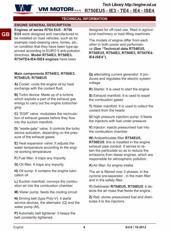
ENGINE GENERAL DESCRIPTIoN
TECHNICAL INFoRmATIoN
Engines of series R754 EU5 - R756 EU5 were designed and manufactured to be installed on road vehicles, such as for example road-cleaning vans, lorries, etc., on condition that they have been type-ap-proved according to EURO 5 anti-pollution directives. model R754IE3, R756IE3, R754TE4-IE4-ISE4 engines have been
designed for off-road use, fitted in agricul-tural machinery or load lifting machines.
The models of engine differ from each other in both power and performan-ce (See “Technical data R754EU5, R756EU5, R754IE3, R756IE3, R754TE4-IE4-ISE4”).
main components R754IE3, R756IE3, R754EU5, R756EU5
A) Cooler: cools the engine oil by heat exchange with the coolant fluid.
B) Turbo device: Made up of a turbine which exploits a part of the exhaust gas energy to carry out the engine turbochar-ging.
C) “EGR” valve: modulates the recircula-tion of exhaust gasses before they flow into the suction manifold.
D) “waste-gate” valve: It controls the turbo device activation, depending on the pres-sure of the exhaust gases.
E) Heat expansion valve: It adjusts the water temperature according to the engi-ne working temperature
F) Fuel filter: It traps any impurity
G) Oil filter: It traps any impurity
H) Oil sump: It contains the engine lubri-cation oil
L) Suction manifold: conveys the combu-stion air into the combustion chamber.
m) Water pump: feeds the cooling circuit
N) Driving belt (type Poly-V): it starts service devices, the alternator (Q) and the water pump (M).
P) Automatic belt tightener: it keeps the belt constantly tightened.
Q) alternating current generator: It pro-duces and regulates the electric system voltage
R) Starter: It is used to start the engine
S) Exhaust manifold: It is used to expel the combustion gases
T) Water manifold: It is used to collect the coolant from the heads
U) high pressure injection pump: It feeds the injectors with fuel under pressure
V) Injector: injects pressurised fuel into the combustion chamber.
W) Antiparticulate filter R754EU5, R756EU5: this is installed in the engine exhaust pipe conduit. It serves to re-tain the particulate so as to reduce the emissions from diesel engines, which are responsible for atmospheric pollution.
X) Air filter: for engine intake.
The air is filtered over 3 phases: in the cyclone pre-separator , in the main filter and in the safety filter.
Y) Debimeter R754EU5, R756EU5: it de-tects the air mass that feeds the engine.
Z) Rail: stores pressurised fuel and distri-butes it to the injectors.
Tech Library http://engine.od.ua

R750EU5 - IE3 - TE4 - IE4 - ISE4
English 9 Ed.8 / �0-20�2
GB
Tech Library http://engine.od.ua

R750EU5 - IE3 - TE4 - IE4 - ISE4
English �0 Ed.8 / �0-20�2
GB
main components R754TE4 - IE4 - ISE4
A) Cooler: cools the engine oil by heat exchange with the coolant fluid.
B) Turbo device: Made up of a turbine which exploits a part of the exhaust gas energy to carry out the engine turbochar-ging.
C) “EGR” valve: modulates the recircula-tion of exhaust gasses before they flow into the suction manifold.
D) “waste-gate” valve: It controls the turbo device activation, depending on the pressure of the exhaust gases (only for R754IE4).
E) Heat expansion valve: It adjusts the water temperature according to the engi-ne working temperature
F) Fuel filter: It traps any impurity
G) Oil filter: It traps any impurity
H) Oil sump: It contains the engine lubri-cation oil
L) Suction manifold: conveys the combu-stion air into the combustion chamber.
m) Water pump: feeds the cooling circuit
N) Driving belt (type Poly-V): it starts service devices, the alternator (Q) and the water pump (M).
P) Automatic belt tightener: it keeps the belt constantly tightened.
Q) alternating current generator: It pro-duces and regulates the electric system voltage
R) Starter: It is used to start the engine
S) Exhaust manifold: It is used to expel the combustion gases
U) high pressure injection pump: It feeds the injectors with fuel under pressure
V) Injector: injects pressurised fuel into the combustion chamber.
W) Antiparticulate filter: this is installed in the engine exhaust pipe conduit. It serves to retain the particulate so as to reduce the emissions from diesel engines, which are responsible for atmospheric pollution.
X) Air filter: for engine intake.
The air is filtered over 3 phases: in the cyclone pre-separator , in the main filter and in the safety filter.
Y) Debimeter: it detects the air mass that feeds the engine.
Z) Rail: stores pressurised fuel and distri-butes it to the injectors.
Tech Library http://engine.od.ua

R750EU5 - IE3 - TE4 - IE4 - ISE4
English �� Ed.8 / �0-20�2
GBDPF Filter (W)
Air Filter (X)
Debimeter (Y)
Intake Manifold
(L)
Exhaust Manifold (S)
Turbo (B)
“waste-gate” valve (D)
Injector (V)
Common RAIL (Z)
Heat Exchanger (A)
Starter Motor (R)
Fuel Filter (F)
High Pressure Pump (U)
Alternator Belt (N)
Belt Tensioner (P)
Coolant Pump (M)
Alternator (Q)
Thermostatic valve (E)
EGR Valve (C)
Oil Filter (G)
Oil Pan (H)
Tech Library http://engine.od.ua

R750EU5 - IE3 - TE4 - IE4 - ISE4
English �2 Ed.8 / �0-20�2
GB
TECHNICAL DATA (R754 EU5-R756 EU5)
These technical data and specifications refer exclusively to standard VM MOTORI S.P.A. engines.
Unit of measure-
mentR754EU5 R756EU5
DimensionsA mm 704 943
B mm 602 602
C mm 722 734
Unit of measure-
mentR754EU5 R756EU5
General dataCycle Four stroke diesel
Total displacement Liters 2,970 4,455
Number of cylinders nr. 4 6
Bore and stroke mm 94x107 94x107
Compression ratio 17,8 ± 0,5:1 17,8 ± 0,5:1
Intake Turbocharged and inter-cooled circuit - (Dry) air filter
Cooling Water circuit
TECHNICAL DATA
Tech Library http://engine.od.ua

R750EU5 - IE3 - TE4 - IE4 - ISE4
English �3 Ed.8 / �0-20�2
GB
Unit of measure-
ment R754EU5 R756EU5
Cooler water/oil
Crankshaft rotationAnticlockwise (observing the engine from the handwhe
el side)
Combustion sequence 1-3-4-2 1-5-3-6-2-4
Timing
Pushrods and rocker arms
With hydraulic tappets and camshaft
Gear cascade control and camshaft fitted on the crankbase
Minimum idling speed (standard engine) rpm 800 +/-50 750 +/-50
Dry shipping weight of engine kg 260 335
Maximum permanent lengthwise inclination (with handwheel up) degrees 30° 30°
Maximum permanent lengthwise inclination (with handwheel down) degrees 35° 35°
Maximum permanent crosswise inclination degrees 30° 30°
Power and torque
Maximum operating speed rpm 3000 3000
Maximum power kW (CV) @ rpm 74 (100) @ 3000 120 (163) @ 3000
Maximum torque Nm (kgm) @ rpm 340 (34,68) @ 1350 500 (51) @ 1350
Consumption at maximum power
Specific fuel consumption g/kWh 274 254
Specific oil consumption g/KWh 0,2 0,2
Fuel supply circuit Type of injection Common Rail direct injection
Type of fuel
The engine has been designed to be powered by standard fuels available on the European market (according to specifications DIN EN 590). If it is to be powered by
BIODIESEL fuels (according to specifications UNI EN 14214), it can be mixed, up to 5%, with fuel available on the
European market (according to regulation DIN EN 590).
i ImPoRTANT
Do not use fuels with specifications other than those indicated.
Tech Library http://engine.od.ua

R750EU5 - IE3 - TE4 - IE4 - ISE4
English �4 Ed.8 / �0-20�2
GB
Unit of measure-
ment R754EU5 R756EU5
Fuel supply Gear pump
Injector supply High pressure injection pump
Lubrication circuit
Type of lubrication Forced lubrication
Circuit fuel supply Rotor pump
Oil change including filter (standard sump) liters (kg) 10 (8,7)
13,8 (12) ÷ 18.9 (16,5)The oil quantity at maxi-mum level ( 12÷16,5 kg) depends on the capacity of the oil sump with which the engine is equipped.
Oil quantity at minimum level (standard sump) liters (kg) 5,8 (5,1) 7,5 (6,6)
Oil quantity at maximum level (standard sump) liters (kg) 8,5 (7,4) 10,9 (9,5)
Oil pressure at minimum speed (with started engine) bar 1,4 - 1,8
Oil cooling Oil/water cooler
Cooling circuit
Total capacity of cooling circuit (excluding radiator and relevant pipes) liters 5 7,5
Setting pressure of the expansion tank plug bar 1,1 1,1
Coolant 50% demineralised or distilled water and 50% Petronas Paraflu
Up (protective radiator fluid with monoethylene glycol and organic inhibitor formulation complying with ASTM D 3306 type 1 Standards)
Coolant maximum temperature alarm °C 107 107
Electric system
Nominal voltage V 12 12
Alternating current generator (nominal voltage) V 14 14
Alternating current generator (nominal current) A 105 105
Starter motor output kW 2,5 2,5
Recommended battery capacity Ah 140 140
Battery breakaway current A 950 950
Suction circuit
Maximum depression allowed with new air filter mbar 40 40
Tech Library http://engine.od.ua

R750EU5 - IE3 - TE4 - IE4 - ISE4
English �5 Ed.8 / �0-20�2
GB
TECHNICAL DATA (R754 IE3-R756 IE3)
Table 2: Technical data of the engine
These technical data and specifications refer exclusively to standard VM MOTORI S.P.A. engines.
Unit of measure-
mentR754IE3 R756IE3
DimensionsA mm 704 943
B mm 601 601
C mm 722 734
Unit of measure-
mentR754IE3 R756IE3
General dataCycle Four stroke diesel
Total displacement Liters 2,970 4,455
Number of cylinders nr. 4 6
Bore and stroke mm 94x107 94x107
Compression ratio 17,8 ± 0,5:1 17,8 ± 0,5:1
Intake Turbocharged and inter-cooled circuit - (Dry) air filter
Cooling Water circuit
Tech Library http://engine.od.ua

R750EU5 - IE3 - TE4 - IE4 - ISE4
English �6 Ed.8 / �0-20�2
GB
Unit of measure-
ment R754IE3 R756IE3
Cooler water/oil
Crankshaft rotationAnticlockwise (observing the engine from the handwhe
el side)
Combustion sequence 1-3-4-2 1-5-3-6-2-4
Timing
Pushrods and rocker arms
With hydraulic tappets and camshaft
Gear cascade control and camshaft fitted on the crankbase
Minimum idling speed (standard engine) rpm 800 +/-50 750 +/-50
Dry shipping weight of engine kg 260 335
Maximum permanent lengthwise inclination (with handwheel up) degrees 30° 30°
Maximum permanent lengthwise inclination (with handwheel down) degrees 35° 35°
Maximum permanent crosswise inclination degrees 30° 30°
Power and torque
Maximum operating speed rpm 3000 3000
Maximum power kW (CV) @ rpm 74 (100) @ 3000 120 (163) @ 3000
Maximum torque Nm (kgm) @ rpm 420 (42.80) @ 1000 500 (50.90) @ 1400
Consumption at maximum power
Specific fuel consumption g/kWh 254 284
Specific oil consumption g/kWh 0,2 0,2
Fuel supply circuit Type of injection Common Rail direct injection
Type of fuel
The engine has been designed to be powered by standard fuels available on the European market (according to specifications DIN EN 590). If it is to be powered by
BIODIESEL fuels (according to specifications UNI EN 14214), it can be mixed, up to 5%, with fuel available on the
European market (according to regulation DIN EN 590).
i ImPoRTANT
Do not use fuels with specifications other than those indicated.
Tech Library http://engine.od.ua
R750EU5 - IE3 - TE4 - IE4 - ISE4
English �7 Ed.8 / �0-20�2
GB
Unit of measure-
ment R754IE3 R756IE3
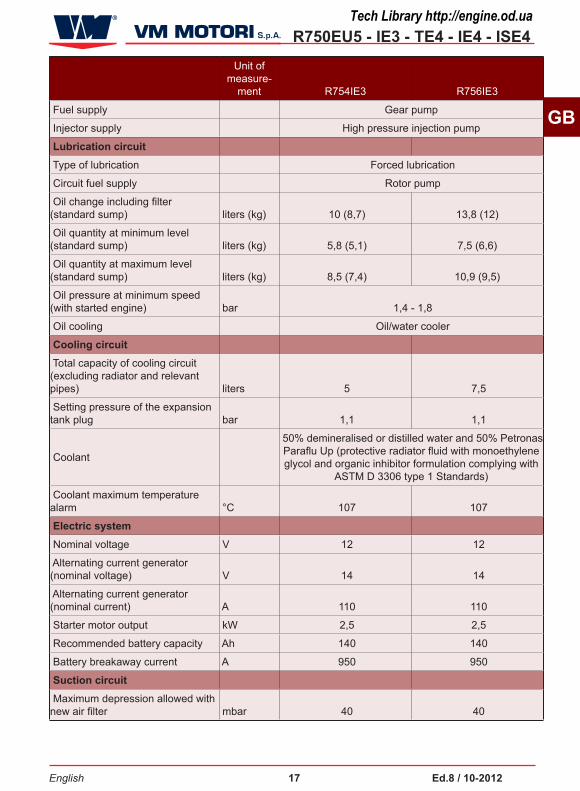
Fuel supply Gear pump
Injector supply High pressure injection pump
Lubrication circuit
Type of lubrication Forced lubrication
Circuit fuel supply Rotor pump
Oil change including filter (standard sump) liters (kg) 10 (8,7) 13,8 (12)
Oil quantity at minimum level (standard sump) liters (kg) 5,8 (5,1) 7,5 (6,6)
Oil quantity at maximum level (standard sump) liters (kg) 8,5 (7,4) 10,9 (9,5)
Oil pressure at minimum speed (with started engine) bar 1,4 - 1,8
Oil cooling Oil/water cooler
Cooling circuit
Total capacity of cooling circuit (excluding radiator and relevant pipes) liters 5 7,5
Setting pressure of the expansion tank plug bar 1,1 1,1
Coolant
50% demineralised or distilled water and 50% Petronas Paraflu Up (protective radiator fluid with monoethylene glycol and organic inhibitor formulation complying with
ASTM D 3306 type 1 Standards)
Coolant maximum temperature alarm °C 107 107
Electric system
Nominal voltage V 12 12
Alternating current generator (nominal voltage) V 14 14
Alternating current generator (nominal current) A 110 110
Starter motor output kW 2,5 2,5
Recommended battery capacity Ah 140 140
Battery breakaway current A 950 950
Suction circuit
Maximum depression allowed with new air filter mbar 40 40
Tech Library http://engine.od.ua
R750EU5 - IE3 - TE4 - IE4 - ISE4
English �8 Ed.8 / �0-20�2
GB
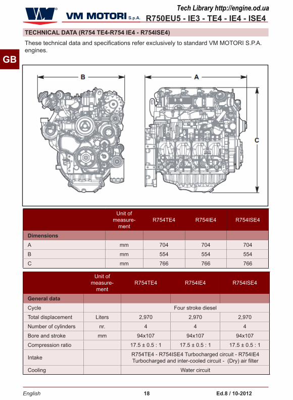
TECHNICAL DATA (R754 TE4-R754 IE4 - R754ISE4)These technical data and specifications refer exclusively to standard VM MOTORI S.P.A. engines.
Unit of measure-
mentR754TE4 R754IE4 R754ISE4
DimensionsA mm 704 704 704
B mm 554 554 554
C mm 766 766 766
Unit of measure-
mentR754TE4 R754IE4 R754ISE4
General dataCycle Four stroke diesel
Total displacement Liters 2,970 2,970 2,970
Number of cylinders nr. 4 4 4
Bore and stroke mm 94x107 94x107 94x107
Compression ratio 17.5 ± 0.5 : 1 17.5 ± 0.5 : 1 17.5 ± 0.5 : 1
Intake R754TE4 - R754ISE4 Turbocharged circuit - R754IE4 Turbocharged and inter-cooled circuit - (Dry) air filter
Cooling Water circuit
Tech Library http://engine.od.ua

R750EU5 - IE3 - TE4 - IE4 - ISE4
English �9 Ed.8 / �0-20�2
GB
Unit of measure-
ment R754TE4 R754IE4 R754ISE4
Cooler water/oil
Crankshaft rotation Anticlockwise (observing the engine from the handwhe el side)
Combustion sequence 1-3-4-2 1-3-4-2 1-3-4-2
Timing
Pushrods and rocker arms With hydraulic tappets and camshaft
Gear cascade control and camshaft fitted on the crankbase
Minimum idling speed (standard engine) rpm 800 800 800
Dry shipping weight of engine kg 260 260 260
Maximum permanent lengthwise inclination (with handwheel up) degrees 30° 30° 30°
Maximum permanent lengthwise inclination (with handwheel down) degrees 35° 35° 35°
Maximum permanent crosswise inclination degrees 30° 30° 30°
Power and torque
Maximum operating speed rpm 2600 2600
Maximum power kW (CV) @ rpm
80 (108.8) @ 2600
55.4 (75.3) @ 2600
Maximum torque Nm (kgm) @ rpm
420 (42.8) @ 1100
310 (31.6) @ 1100
Consumption at maximum power
Specific fuel consumption g/kWh 222.5 217.7
Specific oil consumption g/kWh 0,2 0.2
Fuel supply circuit Type of injection Common Rail direct injection with high pressune injection pump
Type of fuel
The engine has been designed to be powered by standard fuels available on the European market (according to specifications DIN EN 590). If it is to be powered by
BIODIESEL fuels (according to specifications UNI EN 14214), it can be mixed, up to 5%, with fuel available on the European market (according to regulation DIN EN
590).
i ImPoRTANT
Do not use fuels with specifications other than those indicated.
Tech Library http://engine.od.ua

R750EU5 - IE3 - TE4 - IE4 - ISE4
English 20 Ed.8 / �0-20�2
GB
Unit of measure-
ment R754TE4 R754IE4 R754ISE4
Lubrication circuit
Type of lubrication Forced lubrication
Circuit fuel supply Rotor pump
Oil change including filter (standard sump) liters (kg) 11 (9.57)
Oil quantity at minimum level (standard sump) liters (kg)
Oil quantity at maximum level (standard sump) liters (kg)
Oil pressure at minimum speed (with started engine) bar 2
Oil cooling Oil/water cooler
Cooling circuit
Total capacity of cooling circuit (excluding radiator and relevant pipes) liters 5
Setting pressure of the expansion tank plug bar 1,1
Coolant
50% demineralised or distilled water and 50% Petronas Paraflu Up (protective radiator fluid
with monoethylene glycol and organic inhibitor formulation complying with ASTM D 3306 type 1
Standards)
Coolant maximum temperature alarm °C 107
Electric system
Nominal voltage V 12
Alternating current generator (nominal voltage) V 14
Alternating current generator (nominal current) A 110
Starter motor output kW 2,5
Recommended battery capacity Ah 140
Battery breakaway current A 950
Suction circuit
Maximum depression allowed with new air filter mbar 30
Tech Library http://engine.od.ua

R750EU5 - IE3 - TE4 - IE4 - ISE4
English 2� Ed.8 / �0-20�2
GB
GENERAL SAFETY WARNINGSSAFETY INFoRmATIoN
–During the design and construction phases, the Manufacturer paid special attention to the aspects which are liable to cause any risk for the safety and health of people interacting with the engine. Besides complying with the relevant legislation in force, he followed all the “rules for a good construction technique”. The purpose of this information is making users aware of the need to pay the utmost attention to prevent any risk. Caution is however imperative. Safety also depends on all the operators who interact with the engine.
–Read carefully the instructions contained in the manual supplied and those applied on the engine, in particular follow those concerning safety. Spend some of your time reading the instructions to avoid unpleasant accidents.
–Pay attention to the meaning of the sym-bols in the applied plates; their shape and colour have a specific meaning related to safety. Keep them visible and follow the stated information.
–Use the engine only for the tasks autho-rised by the manufacturer and do not tam-per with any device to achieve a different performance from the intended one.
– The staff carrying out any type of inter-vention throughout the life of the engine should have precise technical skills, specific abilities and experiences acquired and acknowledged in this sector. The lack of these requirements may cause dama-ges to people’s safety and health.
–All the installation phases should have been taken into account since the deve-lopment of the initial project. The designer has to observe with the engine fixing poin-ts and the general indications provided by the manufacturer.
–Carry out the handling of the engine in compliance with the information stated directly on the engine, on the packaging and in the operating instructions supplied by the manufacturer.
–When lifting or transporting unpacked engines use means of appropriate load capacity which must be properly ancho-red.
–When lifting and transporting packaged engines, means of appropriate load capa-city as stated on the packaging itself.
–Before carrying out other transfers, crea-te the conditions required to guarantee stability and to prevent any engine part from being damaged.
–Before starting the installation, the instal-ler has to implement a “safety plan” and to follow the designer’s indications. Do not make changes to the engine components for any reason.
– It is necessary to make sure that the in-stallation area is fitted with all intake, fuel supply and exhaust connections.
–The manufacturer cannot be held re-sponsible for any damage resulting from the misuse of the engine, from the failure to follow the indications contained in this manual and from any tampering with or change made without the manufacturer’s authorization.
Tech Library http://engine.od.ua

R750EU5 - IE3 - TE4 - IE4 - ISE4
English 22 Ed.8 / �0-20�2
GB
–If appropriate, before using the engine for the first time, after gathering all the necessary information, simulate a few trial manoeuvres to identify the controls and their main functions, especially those related with starting and stop operations.
–Do not operate the engine in a closed and insufficiently ventilated environment; the exhaust fumes are harmful and can have serious consequences on people’s health.
–Do not keep using the engine if ano-malies are detected and in particular if suspect vibrations occur.
–In case of anomaly, stop immediately the engine or reduce the speed as much as possible and reach the closest assistance centre.
–Start again the engine only when the normal operating conditions have been restored.
–Unless otherwise stated, all interventions should be carried out when the engine has been stopped, cooled down and the ignition key has been removed. Those authorized to carry out these interventions should follow all the precautions needed to guarantee the safety of the people involved, in compliance with the require-
ments laid down in the applicable legisla-tion regarding safety at the workplace.
–Keep the equipment as much efficient as possible and carry out the scheduled maintenance operations established by the manufacturer. A good maintenance will ensure the highest performance, a longer working lifetime and a constant compliance with safety requirements.
–Replace any worn part with original spare parts. Use the oils and greases re-commended by the manufacturer. All this will ensure the engine good operation and the prescribed safety level.
–Do not throw away any polluting ma-terial in the environment. Carry out their disposal in compliance with the relevant legislation in force.
–During all maintenance operations always use the individual protection clothing and/or devices indicated in the operating instructions supplied by the manufacturer and those provided by the applicable legislation concerning safety at the workplace.
–All maintenance operations should be carried out by using suitable and efficient equipment and tools.
SAFETY WARNINGS FoR THE ENVIRoNmENTAL ImPACTEach organization is responsible for implementing procedures aimed at identifying, evaluating and controlling the environmental impact of its own activities (products, services, etc.).
The procedures to be followed to identi-fy any significant environmental impact should take into account the following factors:
–Emissions in the atmosphere
–Discharged liquids
–Waste disposal
–Soil contamination
–Use of raw materials and natural resour-ces
– Local problems related to the environ-mental impact
In order to reduce the environmental impact, the manufacturer provides below a few indications to be taken into account by all those who will interact with the engi-ne throughout its expected life.
Tech Library http://engine.od.ua

R750EU5 - IE3 - TE4 - IE4 - ISE4
English 23 Ed.8 / �0-20�2
GB
SAFETY WARNINGS FoR THE ELECTRICAL EQUIPmENT
RESIDUAL RISKS
–All packaging components should be di-sposed of in accordance with the legisla-tion in force in the country where disposal takes place.
–When installing the engine, ensure a suitable air renewal in the environment to protect the operators from a high concen-tration of harmful substances.
–During operation and maintenance, do not throw away polluting products (oils, greases, etc) in the environment and carry out the differentiated waste disposal
according to the composition of the diffe-rent materials and in compliance with the legislation in force. Electric and electronic components should be carried out as special waste.
–Keep the exhaust pipelines efficient to limit the noise level of the engine and to reduce atmospheric pollution.
–While decommissioning the engine, divide all the components depending on their chemical composition and dispose of them accordingly.
The electrical equipment was designed and manufactured according to the provi-sions of the standards in force on the mat-ter. The list specifies some warnings to be complied with for the correct operation of the electrical equipment.
–Do not use boosters or quick starters to start the engine.
–Do not disconnect the electrical power supply when the engine is ON.
Before disconnecting the electrical power supply, turn off the engine and wait for at least 30 sec. so that the electronic control unit can perform the “after -run” procedure.
–Before performing arc welding on the frame where the engine is installed, ALWAYS disassemble the electronic control unit and protect all electrically connected devices that are installed close to the negative pole (mass).
During the design and construction phases, the Manufacturer paid special attention to the aspects which are liable to cause any risk for the safety and health of people interacting with the engine.
Despite this, some potential and hidden risks still exist.
Danger of injuring your arms
Do not put your hands inside any movin-gpart.
Danger of being burnt
Pay attention to hot surfaces
Tech Library http://engine.od.ua
R750EU5 - IE3 - TE4 - IE4 - ISE4
English 24 Ed.8 / �0-20�2
GB
RECommENDATIoNS FoR HANDLING AND INSTALLATIoNHANDLING AND INSTALLATIoN INFoRmATIoN
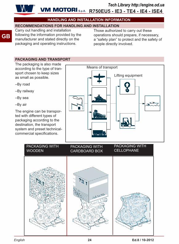
PACKAGING AND TRANSPoRT
PACKAGING WITH WOODENCASE
PACKAGING WITH CARDBOARD BOX
PACKAGING WITH CELLOPHANE
Carry out handling and installation following the information provided by the manufacturer and stated directly on the packaging and operating instructions.
Those authorized to carry out these operations should prepare, if necessary, a “safety plan” to protect and the safety of people directly involved.
The packaging is also made according to the type of tran-sport chosen to keep sizes as small as possible.
–By road
–By railway
–By sea
–By air
The engine can be transpor-ted with different types of packaging according to the destination, the transport system and preset technical-commercial specifications.
Means of transport
Lifting equipment
Tech Library http://engine.od.ua

R750EU5 - IE3 - TE4 - IE4 - ISE4
English 25 Ed.8 / �0-20�2
GB
In order to guarantee the perfect con-servation of all engine components, an “overseas” packaging should be used in case of maritime transport.
The packaging contains all the informa-tion needed to carry out the loading and unloading operations.
During transport, make sure the load is properly secured to the means of transport to avoid unexpected displace-ments.
When transporting the uncovered engine by road, use the lifting points provided to secure it steadily and prevent compo-nents from being damaged.
UNPACKINGFollow the procedure below.
1- Remove the cover of the packaging.
The packaging includes a bag with all the relevant technical documentation and standard components.
2-While unpacking, make sure the com-ponents are intact and their quantity is correct.
3- Place the lifting device as shown in the figure.
4- Loosen the screws (A) and disassem-ble the side supports (B).
5- Move the engine to the installation area.
If necessary, keep the material in case you need to pack the engine in the future.
In case of any damage or missing part, contact the manufacturer’s Assistance Service to establish the procedure to be adopted.
The packaging material should be sui-tably eliminated in compliance with the applicable legislation.
Screw (A)
Stay (B)
Tech Library http://engine.od.ua

R750EU5 - IE3 - TE4 - IE4 - ISE4
0°
max 5°
English 26 Ed.8 / �0-20�2
GB
HANDLING AND LIFTING
Secure the engine with a lifting device (lifting beam) of appropriate capacity.
The angle formed by the lifting device chains must not exceed 5°, as shown in the figure.
–Hook the lifting device to the fixing points as shown in the figure.
–Before carrying out the lifting, identify the barycentre position of the load.
The brackets of the fixing points have been designed to lift the engine only without any additional weight. Do not lift the engine using a different proce-dure from the prescribed one; othe-rwise, the warranty for damages will be invalidated.
Tech Library http://engine.od.ua

R750EU5 - IE3 - TE4 - IE4 - ISE4
English 27 Ed.8 / �0-20�2
GB
ENGINE SToRAGEThe manufacturer supplies the engine with a protection treatment which is valid for 6 months from the delivery date.
If the engine is still not being used 6 months after delivery, then a specific “protection procedure” must be car-ried out in order to extend the storage period for a further 6 months.
The staff carrying out any type of inter-vention throughout the life of the engine should have precise technical skills, specific abilities and experiences acquired and acknowledged in this sector. The lack of these requirements may cause dam-ages to people’s safety and health.
Vm motori recommends that this pro-tection procedure is only carried out by Vm-authorised personnel.
– All packaging components should be disposed of in accordance with the legislation in force in the country where disposal takes place.
The protection procedure is only con-sidered complete when all the follow-ing tasks have been performed:
�) protection against external corro-sion
2) protection against internal corrosion
3) packaging and storage
This procedure is valid for the follow-ing engine situations:
• on a vehicle
• on a pallet
For engines on pallets, it is necessary to install the following accessories for engine start-up:
• battery
• fuel tank
• cooling radiator (for liquid-cooled engines only)
• command belt for the alternating cur-rent generator
• command belt for the water pump (for liquid-cooled engines only)
�) EXTERNAL PRoTECTIoN
UNPAINTED SURFACES: the unpainted metal components and surfaces (for instance the engine handwheel) must be protected with “FL mECA FLUID / P��8V” anticorrosion oil.
RUBBER ComPoNENTS: unpainted manifolds and pipes must be protected with talcum powder. Check the tighten-ing of the relative fixing clips.
DRIVE BELTS: after applying the internal protection, remove the belts and put them into storage. Protect the surfaces of the metal pulleys with “FL mECA FLUID / P��8V” spray.
ENGINE oPENINGS: Seal all the engine openings, including the exhaust. Use cardboard, plywood or metal covers, making sure they do not leave behind any fragments of material. All the engine openings (e.g. air suction ducts or turbocharger air inlet) must be pro-tected with covers or guards to prevent the entry of solids, liquids or dusts that delay the evaporation of the anticor-rosion agents. Apply plugs to the fuel inlet and outlet pipes of the injection system.
Tech Library http://engine.od.ua

R750EU5 - IE3 - TE4 - IE4 - ISE4
English 28 Ed.8 / �0-20�2
GB
BATTERY: Disconnect the battery. When it is fully charged, store it in a safe place. Before doing this, protect the terminals against corrosion by ap-plying an anti-rust spray.
2) INTERNAL PRoTECTIoN ComBUSTIoN CHAmBER: Remove the heating glowplugs from the head, check the piston is in its lowest stroke position (lower standstill point), then spray with Petronas PRoT 30 m pro-tective oil. Repeat the operation for the other cylinders, then reinstall the glowplugs.
TURBoCHARGER: Remove the inlet plug from the pipe that delivers oil to the turbocharger, and fill with Petronas PRoT 30 m protective oil. Replace the inlet plug, applying the correct tighten-ing torque.
ELECTRIC ComPoNENTS: Apply anti-corrosion spray to the electric contacts and connectors.
AIR SUCTIoN SYSTEm: check the air filter is in good condition, and no for-eign bodies/liquids are present:
If the air filter is damaged, replace it
If there are any foreign bodies, remove them
LUBRICATIoN SYSTEm: this procedure must be carried out together with the injection system protection procedure.
• Using the oil dipstick and check whether there is engine oil in the sump.
• Drain the oil from the sump.
• Fill the engine with Petronas PRoT 30 m protective oil.
•
•
• Check the coolant level (for water-cooled engines only). The coolant mixture must be 50% demineralised or distilled water and 50% Petronas Paraflu Up (protective radiator fluid with monoethylene glycol and organic inhibitor formulation complying with ASTm D 3306 type � Standards).
• Start up the engine and run it until it reaches the right temperature for wa-ter-cooled engines (about 70°- 80°C); for air-cooled engines, run the engine for about 20 (twenty) minutes.
• With the engine up to temperature, carry on for about 5 minutes so that the system components are lubricated.
• Switch off the engine and wait for it to cool down.
• Drain the oil from the sump.
• Drain off the coolant.
• Check for any fluid leakage (and make any necessary repairs).
• Disconnect the engine from all the components used for the test.
Tech Library http://engine.od.ua

R750EU5 - IE3 - TE4 - IE4 - ISE4
English 29 Ed.8 / �0-20�2
GB
INJECTIoN SYSTEm: this procedure must be carried out together with the lubrication system protection proce-dure.
• make sure there are no deposits or sediments in the fuel tank.
• Prepare a mixture of diesel fuel com-plying with the DIN EN 590 specifica-tions, and Petronas DIESEL TmF PLUS additive. The ratio must be at least �:400 (� litre of additive to 400 litres of fuel). If you use Biodiesel (complying with the UNI EN 14214 specifications), it must be mixed with diesel fuel up to 5%;
Vm motori, however, recommends the use of diesel without Biodiesel.
The use of any other fuel is forbidden.
• Fill the tank with this fuel mixture.
• Where relevant, check there is no interference between the radiator fan blades and the relative air duct.
Start up the engine and run it until it reaches the right temperature for wa-ter-cooled engines (about 70°- 80°C); for air-cooled engines, run the engine for about 20 (twenty) minutes.
• Drain the fuel tank.
• Check for any fluid leakage (and make any necessary repairs).
• Switch off the engine and wait for it to cool down.
SEAWATER SYSTEm (for marine engines and on-board auxiliary units only): this procedure must be carried out together with the injection system protection procedure.
• Connect the seawater intake of the seawater pump to an auxiliary tank
containing a mixture of 40% freshwater and 60% Petronas Paraflu Up (protec-tive radiator fluid with monoethylene glycol and organic inhibitor formula-tion complying with ASTm D 3306 type � Standards), making sure it seeps out from the drainage point.
• Check for any fluid leakage (and make any necessary repairs).
• Switch off the engine and wait for it to cool down.
• Disconnect the engine from all the components used for the test
3) SToRAGE CoNDITIoNS
- Engines on pallets
After applying the anticorrosion protection, the engine must be placed in a dry, well-ventilated environment and adequately covered. The covering must be applied in such a way that air can circulate around the engine, pre-venting the formation of condensation.
- Engines on vehicles
The vehicle must be stored so as to mi-nimise exposure to atmospheric agents
Tech Library http://engine.od.ua
R750EU5 - IE3 - TE4 - IE4 - ISE4
English 30 Ed.8 / �0-20�2
GB
START-UP
- Engines on pallets
Remove the covers and protective elements applied to the engine open-ings (for instance, air suction ducts or turbocharger air inlet, exhaust gas ducts or turbocharger guard).
Check there is no damage to the ex-ternal engine components; make any necessary repairs.
Clean the throats of the metal belt pul-leys, using a suitable solvent. Install the service belts
Check the rubber tubes and manifolds are in good condition, and check the tightening of the relative fixing clips; if they are damaged, replace them.
All surfaces and components pro-tected with “FL mECAFLUID / P��8 V” protective oil can be cleaned with a suitable solvent.
Check the level of the fluids: engine oil and coolant. Top up if necessary.
- Engines on vehiclesCheck there is no damage to the ex-ternal engine components; make any necessary repairs.
Clean the throats of the metal belt pul-leys, using a suitable solvent. Install the service belts.
Check the rubber tubes and manifolds are in good condition, and check the tightening of the relative fixing clips; if they are damaged, replace them.
All surfaces and components pro-tected with “FL mECAFLUID / P��8 V” protective oil can be cleaned with a suitable solvent.
Check the level of the fluids: engine oil and coolant. Top up if necessary.
Nothing needs to be done to remove the internal protection (either for engines on pallets or on vehicles).
Tech Library http://engine.od.ua
R750EU5 - IE3 - TE4 - IE4 - ISE4
English 3� Ed.8 / �0-20�2
GB
In order to ensure the highest performan-ce while protecting people, the product itself and the environment, a full project has to be developed before carrying out the installation.
The design phase should take into account the technical data of the engine (see”Technical data”) and all the risks whi-ch may occur during its expected lifetime, from installation to disposal.
During the design and installation phases, it is advisable to consult the service manual supplied by Vm moTo-RI S.P.A..
Further information are available in the website: www.vmmotori.it, in the “Con-tacts – Request Info” section.
INSTALLATIoN DESIGN
Tech Library http://engine.od.ua

R750EU5 - IE3 - TE4 - IE4 - ISE4
English 32 Ed.8 / �0-20�2
GB
oPERATING INFoRmATIoN
RECommENDATIoNS FoR USE AND oPERATIoN
RECommENDATIoNS FoR USE
Sensor (A)
The engine has been designed and manufactured to satisfy all the operating conditions indicated by the manufacturer.
The engine is delivered by the factory in the running order.
However, during operation the following indications should be observed:
1- During running-in (first 50 working hours) and throughout the engine lifetime, carry out the maintenance in compliance with the intervals established by the ma-nufacturer. (See “Engine maintenance”)
2- Avoid using the engine at the highest speed for prolonged periods during run-ning- in.
3- If the engine is not regularly used, it is advisable to start and take it to the working temperature (70÷80°C) at least once a month.
4- DO NOT use the engine at maximum performances before it has reached the working temperature (70÷80 °C).
5- When starting the engine for the first time, run it at no-load for a few minutes and make sure that the oil pressure value matches the one stated in the table. (See “Technical data )” - “Lubrication circuit”)
6 - In the event that the ambient tempera-ture is low during use, proceed as follow:
□ preheat the engine adequately.
□ when ambient temperatures are lower than -10°C, contact the manufac-turer of the vehicle regarding the instal-lation of devices which facilitate start-up and prevent ice forming in the engine oil vapour recovery
Tampering with any device to achieve a different performance from the intended one can entail risks for people’s safety and health as well as economic damages.
7 - Use oils and lubricants with suitable features (viscosity grade, specifications and operating temperature). (See “Re-commended lubricants”)
8 - If the “water in fuel” indicator lights up, proceed as follows:
– Turn off the engine and remove the ignition key.
– Let the engine cool down adequately to avoid being burnt.
– Prepare a container of appropriate capacity.
– Unscrew the water sensor (A) of the filter and let the fuel flow until it proves to be water-free.
– Screw the sensor (A) back.
Tech Library http://engine.od.ua

R750EU5 - IE3 - TE4 - IE4 - ISE4
English 33 Ed.8 / �0-20�2
GBBe careful to ensure that the fuel in the filter does not drain completely out. If it does, remove it (see “Fuel filter replacement.”), fill it manually and then repeat the bleeding operation. Do not throw away any polluting material in the environment. Carry out their di-sposal in compliance with the relevant legislation in force.
9 - When an alarm signal (visual and/or acoustic) is triggered by the control panel this indicates that there is a malfunction of some kind.
In the presence of anomalies, the electronic engine management system activates protective strategies and also the limitation of the engine performan-ces if necessary.
In these conditions it is possible to check the ignition of the indicator light (mIL) for the engines R750EU5 or of the system indicator light (SYS) for the en-gines R750TE3-IE3, R750TE4-IE4-ISE4.
Do not continue to use the engine with the mIL indicator light on, instead con-tact an authorized Vm motori assistan-ce centre.
Do not attempt to disconnect the mIL indicator light sensor in order to clear the signal. Vm motori does not assume any liability for economic damages or risks to personal safety. For more information, refer to the documentation provided by the manufacturer of the vehicle/device in which the engine is installed.
To solve the problem, proceed as indica-ted.
– Turn off the engine.
–Consult chapter “INFORMATION ABOUT FAILURES” for the action to be taken and details of how to deal with the causes that triggered the state of emergency.
– In case of doubts, never operate directly, but contact a VM authorised workshop.
If the engine is not regularly used, it is advisable to start and take it to the working temperature (70÷80°C) at least once a month.
If the engine is installed for use in emergencies, for example in the case of generators, it must be started at least once per month.
Tech Library http://engine.od.ua

R750EU5 - IE3 - TE4 - IE4 - ISE4
English 34 Ed.8 / �0-20�2
GB
oPERATING THE ENGINE UNDER SPECIFIC CoNDITIoNSThe engine performance is affected by fuel temperature, the temperature and relative humidity of incoming air and altitude.
When using the engine at high altitudes and high air and fuel temperatures, the output is reduced.
For further information contact a VM MO-TORI S.P.A. assistance centre.
R750EU5 engines have an automatic particulate filter regeneration system that can only be activated while the vehicle is running. During this phase, the filter casing reaches temperatures of around 500°C.
During the particulate filter regeneration phase, do not park the vehicle on sur-faces containing flammable materials, which may burn on contact with the exhaust system.
R750IE4 engines have an automatic par-ticulate filter regeneration system that can only be activated while the vehicle is running. During this phase, the filter casing reaches temperatures of around 500°C.
During the particulate filter regeneration phase, do not park the vehicle on sur-faces containing flammable materials, which may burn on contact with the exhaust system.
R750EU5
R750IE4
REGENERATIoN oF THE PARTICLE FILTERThe “Regeneration of the particle filter” is the burning operation of the particles that periodically accumulate in the filter.
In some applications, there may be an indicator light in the instrument panel of the vehicle which indicates the clogging of
the particulate filter .
In the event of activation of this indicator light, for the regeneration of the particu-late filter it is recommended to drive the vehicle at medium-high engine load, until the indicator light turns off.
For more information refer to the instruc-tion book for use and maintenance of the vehicle or contact the customer service network.
In some applications a button may be available for manual regeneration of the particulate filter: to use this button refer to the instruction book for use and mainte-nance of the vehicle.
Tech Library http://engine.od.ua

R750EU5 - IE3 - TE4 - IE4 - ISE4
English 35 Ed.8 / �0-20�2
GB
ENGINE IGNITIoN AND TURNING oFFThe engine is not fitted with a control panel.
For information on the commands and control devices, please see the documen-tation provided by the manufacturer of the vehicle/ device in which the engine is installed.
In the case of turbocharged engines, before switching the engine off it should be run at minimum idle speed for a few minutes in order to avoid damaging the turbocharger.
REFUELLINGDuring refuelling, make sure the fuel does not contain any residue; in this case use specific filters.
–Avoid using fuel mixed with water or other substances which may damage the engine.
– The engine has been designed to be powered by standard fuels available on the European market (according to speci-fications EN 590). If it is to be powered by BIODIESEL fuels (according to specifica-tions UNI EN 14214), it can be mixed, up to 5%, with fuel available on the European market (according to regulation EN 590).
Do not use fuels with specifications other than those indicated.
– For engines model R754EU5 - R756EU5 - R754TE4,IE4,ISE4, use fuel with a low sulphur content. The percentage sulphur must never exceed �0-50 ppm (parts per million).
If the percentage sulphur contained in the fuel exceeds the value indicated, the antiparticulate filter will not work properly.
All fuels are inflammable. Any fuel leaking or dropping on hot surfaces and electric components can cause fires. Do not smoke when refuelling or nearby any filling station.
Tech Library http://engine.od.ua
R750EU5 - IE3 - TE4 - IE4 - ISE4
English 36 Ed.8 / �0-20�2
GB
mAINTENANCE INFoRmATIoN
RECommENDATIoNS FoR mAINTENANCE
ENGINE mAINTENANCE
Keep the equipment as much efficient as possible and carry out the scheduled maintenance operations established by the manufacturer. A good maintenance will ensure the highest performance, a longer operating lifetime and a constant compliance with safety requirements.
Unless otherwise stated, all interven-tions should be carried out when the engine has been stopped, cooled down and the ignition key has been removed.
Those authorized to carry out these
The maintenance operations are subdivi-ded into:
–Maintenance during running-in (first 50
hours)
–Routine maintenance (after running-in)
The frequency stated in the “ routine maintenance” table should be applied to engines which are used regularly.
Some lubricants or components lose their characteristics over time even if the engine is left idle for long periods; the-refore, maintenance intervals should be established considering that these parts need to be replaced not only on the basis of their hours of operation but of ageing as well.
interventions should follow all the precautions needed to guarantee the safety of the people involved, in compliance with the requirements laid down in the applicable legislation con-cerning safety at the workplace.
For each maintenance operation, fill in the “Periodic maintenance operation record sheet” provided, so as to keep a trace of the operations performed and therefore establish the most suitable methods for future operations.
The approximate maximum time during which the chemical-physical characteristi-cs of a few components or lubricants are maintained is stated below.
– 1 year – Lubricant oil
– 1 year - Fuel filter cartridge
– 2 years – Coolant
Tech Library http://engine.od.ua

R750EU5 - IE3 - TE4 - IE4 - ISE4
English 37 Ed.8 / �0-20�2
GB
mAINTENANCE DURING RUNNING-IN (FIRST 50 HoURS)
For each maintenance operation, fill in the “Periodic maintenance operation record sheet” provided, so as to keep a trace of the operations performed and therefore establish the most suitable methods for future operations.
Frequency (�) Component Type of inter-
ventionIntervention procedures Reference
Every �0 hours (Every day)
Engine oil (2) Level control Top up, if nec-essary
See Engine oil level control
Coolant (4) Level control Top up, if nec-essary
See Engine coolant level check
Air filter
Check it is clean
Clean with low pressure com-pressed air.
Check the clog-ging indicator that is installed on the filter body
Clean the filter or, if necessary, replace it with a new one.
See Cleaning and replacement of the air filter
Coolant fluid radiator
Check it is clean
Clean with a soft brush
After the first 50 hours (at the end of running-in)
Oil filter (3) Replacement See Oil filter cartridge re-placement
(1) If an hour counter is not available, the frequency of the interventions should be calcu-lated on the basis of a calendar day: one calen-dar day corresponds to 12 hours of operation.
(2) In hard working conditions, such as dusty environments and operation with extreme loads, change the oil of the engine and the oil filter every 150 working hours. If the engine has not worked for the specified time, it will be necessary to replace the oil and the filter all the same once a year.
(3) If the engine has not been in operation for the length of time indicated, the filter must still be changed at least once every 12 months.
(4) If the engine has not been in operation for the length of time indicated, the fluid must still be changed at least once every 24 months.
(5) If the engine has not been in operation for the length of time indicated, the belt must still be changed at least once every 24 months
Periodic maintenance operation record sheet
For each maintenance operation, fill in the sheet, so as to keep a trace of the operations performed and therefore establish the most suitable methods for future operations.
Tech Library http://engine.od.ua
R750EU5 - IE3 - TE4 - IE4 - ISE4
English 38 Ed.8 / �0-20�2
GB
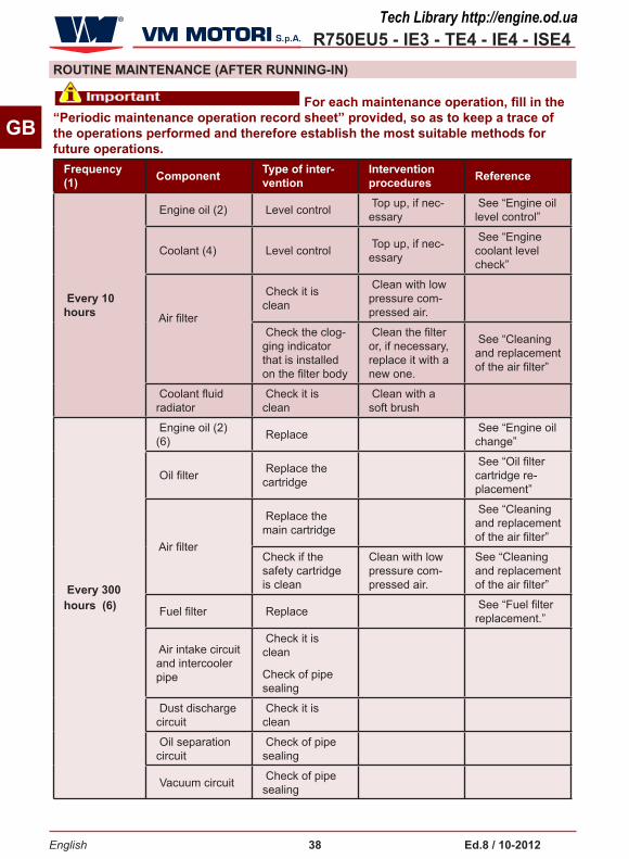
RoUTINE mAINTENANCE (AFTER RUNNING-IN)
Frequency (�) Component Type of inter-
ventionIntervention procedures Reference
Every �0 hours
Engine oil (2) Level control Top up, if nec-essary
See “Engine oil level control”
Coolant (4) Level control Top up, if nec-essary
See “Engine coolant level check”
Air filter
Check it is clean
Clean with low pressure com-pressed air.
Check the clog-ging indicator that is installed on the filter body
Clean the filter or, if necessary, replace it with a new one.
See “Cleaning and replacement of the air filter”
Coolant fluid radiator
Check it is clean
Clean with a soft brush
Every 300 hours (6)
Engine oil (2) (6) Replace See “Engine oil
change”
Oil filter Replace the cartridge
See “Oil filter cartridge re-placement”
Air filter
Replace the main cartridge
See “Cleaning and replacement of the air filter”
Check if the safety cartridge is clean
Clean with low pressure com-pressed air.
See “Cleaning and replacement of the air filter”
Fuel filter Replace See “Fuel filter replacement.”
Air intake circuit and intercooler pipe
Check it is clean
Check of pipe sealing
Dust discharge circuit
Check it is clean
Oil separation circuit
Check of pipe sealing
Vacuum circuit Check of pipe sealing
For each maintenance operation, fill in the “Periodic maintenance operation record sheet” provided, so as to keep a trace of the operations performed and therefore establish the most suitable methods for future operations.
Tech Library http://engine.od.ua

R750EU5 - IE3 - TE4 - IE4 - ISE4
500 oRE
500 HoURS
English 39 Ed.8 / �0-20�2
GBFrequency (�) Component Type of inter-
ventionIntervention procedures Reference
Every 900 hours
Drive belt (type Poly-V) (5) Replace
See “Changing t belt (type Poly-V)”
fuel tank
Clean the fuel tank and check the efficiency of the filler cap.
Air filter Replace the clogging indi-cator
Every 1200 hours Coolant (4) Replace See “Coolant
replacement”
Every 4000 hours
Antiparticulate filter
Perform the regeneration
Apply to an authorised workshop
Every 4000 hours Engine Performing
partial overhaul
Apply to an authorised workshop
Every 8000 hours Engine Performing ge-
neral overhaul
Apply to an authorised workshop
(1) If an hour counter is not available, the frequency of the interventions should be calculated on the basis of a calendar day: one calendar day corresponds to 12 hours of operation.
(2) In hard working conditions, such as dusty environ-ments and operation with extreme loads, change the oil of the engine and the oil filter every 150 working hours. If the engine has not worked for the specified time, it will be necessary to replace the oil and the filter all the same once a year.
The engine oil must in any case be changed, even before the time limit indicated in the scheduled
maintenance programme, if the MIL indicator indicator light comes on with the ECU error 252F - “Engine oil critical mass”..
(3) If the engine has not been in operation for the length of time indicated, the filter must still be changed at least once every 12 months.
(4) If the engine has not been in operation for the length of time indicated, the fluid must still be changed at least once every 24 months.
(5) If the engine has not been in operation for the length of time indicated, the belt must still be changed at least once every 24 months
(6) In engine R756EU5 models with a high capacity oil sump, a special plate is applied on the cover of the engine valves to indicate that the engine oil and the oil filter must be changed every 500 hours instead of every 300.
Periodic maintenance operation record sheet
For each maintenance operation, fill in the sheet, so as to keep a trace of the operations performed and therefore establish the most suitable methods for future operations.
Tech Library http://engine.od.ua

R750EU5 - IE3 - TE4 - IE4 - ISE4
English 40 Ed.8 / �0-20�2
GB
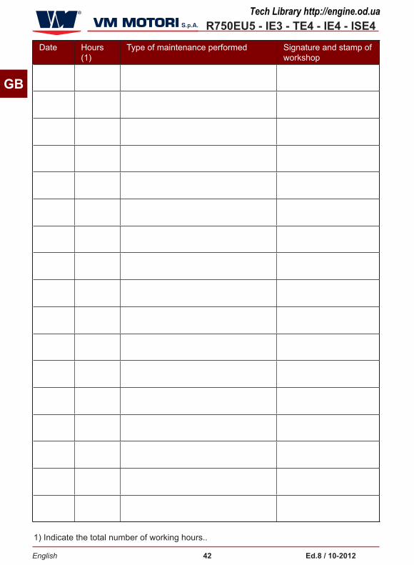
PERIoDIC mAINTENANCE oPERATIoN RECoRD SHEET
For each maintenance operation, fill in the sheet, so as to keep a trace of the operations performed and therefore establish the most suitable methods for future operations.Date Hours
(1)Type of maintenance performed Signature and stamp of
workshop
1) Indicate the total number of working hours..
Tech Library http://engine.od.ua

R750EU5 - IE3 - TE4 - IE4 - ISE4
English 4� Ed.8 / �0-20�2
GB
Date Hours (1)
Type of maintenance performed Signature and stamp of workshop
1) Indicate the total number of working hours..
Tech Library http://engine.od.ua
R750EU5 - IE3 - TE4 - IE4 - ISE4
English 42 Ed.8 / �0-20�2
GB
Date Hours (1)
Type of maintenance performed Signature and stamp of workshop
1) Indicate the total number of working hours..
Tech Library http://engine.od.ua

R750EU5 - IE3 - TE4 - IE4 - ISE4
English 43 Ed.8 / �0-20�2
GB
Date Hours (1)
Type of maintenance performed Signature and stamp of workshop
1) Indicate the total number of working hours..
Tech Library http://engine.od.ua

R750EU5 - IE3 - TE4 - IE4 - ISE4
English 44 Ed.8 / �0-20�2
GB
Date Hours (1)
Type of maintenance performed Signature and stamp of workshop
1) Indicate the total number of working hours..
Tech Library http://engine.od.ua

R750EU5 - IE3 - TE4 - IE4 - ISE4
English 45 Ed.8 / �0-20�2
GB
mAINTENANCE WHEN THE ENGINE IS LEFT IDLE
WASHING THE ENGINEIn order to avoid irreversibly damaging the electrical and electronic components of the engine, do not spray high pressure jets of water or jets of vapour in the direc-tion of these components.
Pay particular attention to:
□ cable connection points and engi-ne wiring electrical connectors
□ alternator, starter motor,
□ injection pump and related fuel supply pump,
□ electro-injectors,
□ electrical sensors installed on the engine,
□ electronic engine management control unit,
□ engine suction air filter and rela-ted air flow meter,
□ fuel filter,
– If you decide to wash the engine, ade-quately protect the above listed compo-nents before washing.
– When washing is complete, start the engine and leave it running for a few minutes until it is completely dry.
If the vehicle/equipment to which the engine is fitted remains inactive, certain maintenance operations must be carried out to ensure the engine remains in full working order.
If the engine is not used for short periods of time, carry out the following interven-tions:
1- Make sure the electric contacts are working properly and, if necessary, protect them with an anti-oxidant spray.
– Check the charge of the battery and the liquid level.
– If necessary, carry out the scheduled maintenance work (See “Engine mainte-nance”).
It is advisable to start the engine bringing it to the operating temperatu-re (70÷80°C) at least once per month. The engine must be started once per month if it is installed for emergency purposes.
If the engine needs to be used in emer-gency conditions, refer to the specific regulations concerning compulsory start-up: if there are no specific regu-lations, you are advised to start up the engine once a month.
If the engine is left idle for prolonged periods, carry out the engine protective treatment to guarantee its efficiency for 6 months and to avoid continuous control and maintenance interventions. If the engine is not used for a further period of time, check the need to repeat the protec-tive treatment for other 6 months. (Vedi “Engine storage”).
Tech Library http://engine.od.ua

R750EU5 - IE3 - TE4 - IE4 - ISE4
English 46 Ed.8 / �0-20�2
GB
mAINTENANCE IN CASE oF ENGINE INACTIVITYAfter a period of inactivity, it is necessary to carry out a few maintenance interven-tions before starting the engine again to ensure its maximum efficiency conditions.
– Check the charge of the battery and the liquid level.
–Make sure the electric contacts are intact and properly working.
– Carry out the operation diagnosis of the engine.
–Check the oil level, and, if necessary, top up or replace it according to the esta-blished intervals (See “Routine mainte-nance (after running-in)”)
–Replace the oil filter according to the established intervals (See “Routine main-tenance (after running-in)”)
–Check the coolant level, and if neces-sary, top up or replace it according to the established intervals (See “Routine maintenance (after running-in)”)
–Replace the fuel filter according to the established intervals (See “Routine main-tenance (after running-in)”)
– Replace the air filter according to the established intervals (See “Routine main-tenance (after running-in)”)
– Tension again the transmission belt
– Check the tightening of the hydraulic unions (See “Control screw tightening and union sealing”)
–Check the rubber gaskets and relevant fixing clips to ensure they are undama-ged.
– Use a cloth soaked in a degreasing product to remove the external protective treatment.
–Start the engine and run it at minimum speed for a few minutes (See “Engine ignition and turning off”)
– If no anomalies are detected, bring the engine to its operating temperature (70÷80°C).
–Turn off the engine and check again the engine oil and coolant level.
Tech Library http://engine.od.ua

R750EU5 - IE3 - TE4 - IE4 - ISE4
English 47 Ed.8 / �0-20�2
GB
CHECKS AND CoNTRoLS
CoNTRoL SCREW TIGHTENING AND UNIoN SEALING
FUEL SUPPLY CIRCUIT BLEEDING
Pump (F)
Bleed screew (E)
The list indicates some of the maintenan-ce, testing and control operations to be carried out on the engine during normal operation.
– Fuel supply circuit bleeding
–Control screw tightening and union sealing
–Engine oil level control
–Engine coolant level check
–Procedure for loosening or tensioning the belt
–Engine oil change
Follow the procedure below.
1- Start the engine and run it at minimum speed for a few minutes.
2-Run the engine at normal speed until the operating temperature (70÷80°C) is reached.
3- Turn off the engine and let it cool down.
This operation must be carried out each time the fuel cartridge is changed
Follow the procedure below.
1- Turn off the engine and remove the ignition key.
2- Let the engine cool down adequately to avoid being burnt.
–Coolant replacement
–Oil filter cartridge replacement
– Fuel filter replacement.
– Cleaning the antiparticulate filter
For each maintenance operation, fill in the “Periodic maintenance operation record sheet” provided, so as to keep a trace of the operations performed and therefore establish the most suitable methods for future operations.
4-Make sure the fixing screws of the main parts are tightened properly.
5- Check the union sealing on the fuel supply circuit.
6- Check the tightening of the clamps.
7- Check any fluid leaks.
Tech Library http://engine.od.ua

R750EU5 - IE3 - TE4 - IE4 - ISE4
English 48 Ed.8 / �0-20�2
GB
3- Prepare a container of appropriate capacity.
4- Loosen the screw (E).
Do not loosen high-pressure pipe unions of the supply circuit (CommoN RAIL system).
5- Operate the pump (F) manually to eliminate air from the circuit.
6-Check that a flow of clean fuel contai-ning no air bubbles is coming out of the bleeder screw (E).
Be careful to ensure that the fuel in the filter does not drain completely out. If it does, remove it (see “Fuel filter replacement.”), fill it manually and then repeat the bleeding operation.
7- Tighten the screw (E).
8- Wipe out the fuel residues before star-ting the engine.
ENGINE oIL LEVEL CoNTRoL
Filler Cap (M)Oil Dipstick (L)
Follow the procedure below.
1- Start the engine and bring it to the ope-rating temperature (70÷80 °C).
2- Turn off the engine and remove the ignition key.
3- Place the engine on a perfectly level surface.
4-Wait a few minutes so that all the oil will flow into the sump.
5-Remove the dipstick (L) and check the oil level.
6- Top up, if necessary, from plug (M). As for the oil quantity, see “Technical data ”.
The oil level should be included between the minimum and maximum marks. Do not mix oils of different brands or with different features. (See “Recommended lubricants”)
Tech Library http://engine.od.ua

R750EU5 - IE3 - TE4 - IE4 - ISE4R750EU5 - R750IE3
English 49 Ed.8 / �0-20�2
GB
ENGINE CooLANT LEVEL CHECKFiller cap (P)Follow the procedure below.
1- Start the engine and bring it to the ope-rating temperature (70÷80 °C).
2- Turn off the engine and remove the ignition key.
3- Let the engine cool down properly.
4- Unscrew the filling plug (P).
open the plug gently to drain the pres-sure.5- Top up, if necessary, from plug (P). As for the liquid quantity and type, see “Technical data ”.
The fluid level must be up to the base of the neck into which the radiator plug is screwed.
For further information, please consult the documentation provided by the manufacturer of the vehicle/device in which the engine is installed.
Tech Library http://engine.od.ua
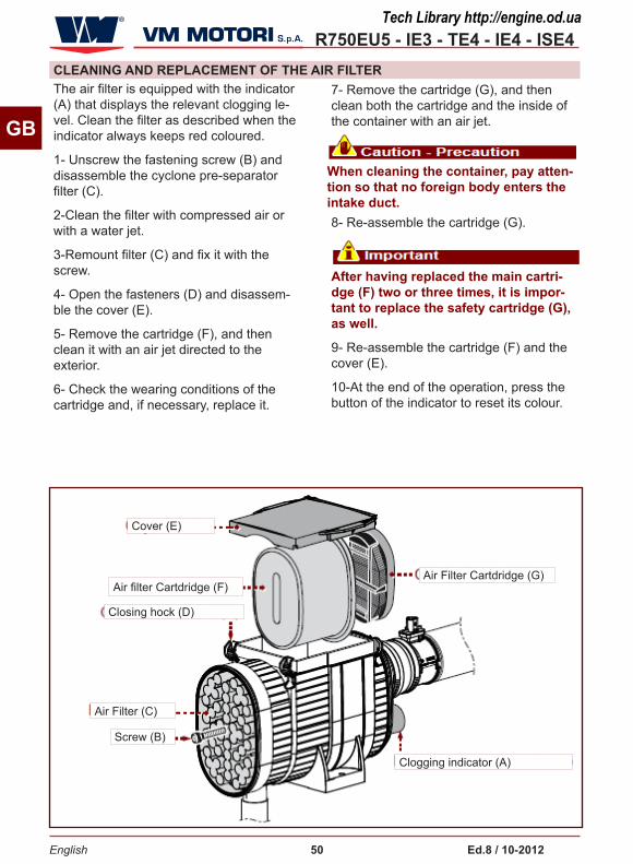
R750EU5 - IE3 - TE4 - IE4 - ISE4
English 50 Ed.8 / �0-20�2
GB
CLEANING AND REPLACEmENT oF THE AIR FILTERThe air filter is equipped with the indicator (A) that displays the relevant clogging le-vel. Clean the filter as described when the indicator always keeps red coloured.
1- Unscrew the fastening screw (B) and disassemble the cyclone pre-separator filter (C).
2-Clean the filter with compressed air or with a water jet.
3-Remount filter (C) and fix it with the screw.
4- Open the fasteners (D) and disassem-ble the cover (E).
5- Remove the cartridge (F), and then clean it with an air jet directed to the exterior.
6- Check the wearing conditions of the cartridge and, if necessary, replace it.
7- Remove the cartridge (G), and then clean both the cartridge and the inside of the container with an air jet.
When cleaning the container, pay atten-tion so that no foreign body enters the intake duct.8- Re-assemble the cartridge (G).
After having replaced the main cartri-dge (F) two or three times, it is impor-tant to replace the safety cartridge (G), as well.
9- Re-assemble the cartridge (F) and the cover (E).
10-At the end of the operation, press the button of the indicator to reset its colour.
Cover (E)
Air filter Cartdridge (F)Air Filter Cartdridge (G)
Air Filter (C)
Screw (B)
Clogging indicator (A)
Closing hock (D)
Tech Library http://engine.od.ua

R750EU5 - IE3 - TE4 - IE4 - ISE4
English 5� Ed.8 / �0-20�2
GB
ENGINE oIL CHANGE
Filler cap (M)
Drain plug (Q)
Follow the procedure below.
Start the engine and bring it to the operating temperature (70÷80 °C)
Turn off the engine and remove the ignition key.
Let the engine cool down adequately to avoid being burnt.
Prepare a container of appropriate capacity. (As for the oil quantity, see “Technical data”.)
Unscrew the load plug (M).
Unscrew the exhaust plug (Q) and let all the oil flow into the container.
Replace the gasket and screw plug (Q) back into place.
•
•
•
•
•
•
•
Lock the plug to a torque of 55 Nm.
Pour the new oil until it reaches the correct level on the dipstick. (See “Engine oil level control”)
Screw again the load plug (M).
Start the engine and bring it to the operating temperature (70÷80 °C). Check for any oil leaks.
Turn off the engine and check the oil level. (See “Engine oil level control”)
•
•
•
•
Tech Library http://engine.od.ua

R750EU5 - IE3 - TE4 - IE4 - ISE4
English 52 Ed.8 / �0-20�2
GB
In R750 EURo5 engines after each oil change the “oil dilution calculation” function must be reset. The function is reset by the diagnosis tool available from authorised workshops or vehicle dealers. If the diagnosis tool is not available, the function can be reset using the following procedure:
�. Turn the ignition key to oN with the engine off
2. Press the accelerator pedal fully down (pedal from 0% to �00%)
3. Wait for 3 seconds before releasing the pedal.
4. Release the pedal, allow it to return to the initial position (0%) and wait a further 3 seconds before pressing it again.
Repeat the procedure described in points 2, 3 and 4, 5 times. In some applications the accelerator pedal pro-cedure is not feasible: proceed using the manual accelerator potentiometer.
VERIFICATIoN: if the procedure has been done correctly, the engine oil low pressure light will flash three times for one second each, with a pause of 0.5 seconds. In some applications the verification is not feasible.
Do not throw the oil in the environment but carry out its disposal in com-pliance with legislation in force in the country where it is used. Use the oils and lubricators recommended by the manufacturer. (See “Recommended lubricants”)
ENGINE oIL DILUTIoN
Reset the ECU parameters (carry out this operation after completing the engine oil change).
Tech Library http://engine.od.ua

R750EU5 - IE3 - TE4 - IE4 - ISE4
English 53 Ed.8 / �0-20�2
GB
CooLANT REPLACEmENT
Filler Cap (P)
Cock (S)
Follow the procedure below.
1- Start the engine and run it at minimum speed for a few minutes. The cooling circuit reaches the operating pressure.
2- Turn off the engine and remove the ignition key.
3- Let the engine cool down adequately to avoid being burnt.
4- Prepare a container of appropriate capacity. As for the liquid quantity, see “Technical data ”.
5-Unscrew the load plug (P).
open the plug gently to drain the pres-sure.
6- Open the cock (S).
If there is no coolant drainage tap, check to see if there is a drain plug. For further information, please consult the documentation provided by the manufacturer of the vehicle/device in which the engine is installed.
7- Let the liquid flow into the container.
8-Close the cock (S).
9- Pour in the new liquid.
The fluid level must be up to the base of the neck into which the radiator plug is screwed. If there is a coolant expan-sion tank, consult the documentation provided by the manufacturer of the vehicle/device in which the engine is installed. As for the liquid quantity and type, see “Technical data ”.
10-Screw again the plug (P).
11-Turn the engine on and keep it running at idle speed for a few minutes to bring it up to working temperature (70÷80°C).
If the fluid level decreases, top it up until it is constantly between the refe-rence marks
12-Turn off the engine and let it cool down properly.
13-Check the coolant level and, if neces-sary, carry out topping-up. (See “Engine coolant level check”)
Do not throw away any polluting material in the environment. Carry out their disposal in compliance with the relevant legislation in force.
Tech Library http://engine.od.ua

R750EU5 - IE3 - TE4 - IE4 - ISE4
English 54 Ed.8 / �0-20�2
GB
oIL FILTER CARTRIDGE REPLACEmENT
Gasket (V)
Oil Filter (U)
Follow the procedure below.
1- Turn off the engine and remove the ignition key.
2- Let the engine cool down adequately to avoid being burnt.
3- Prepare a container to collect any leak.
4-Unscrew filter (U) and replace it.
5-Check the conditions of gasket (V) and, if necessary, replace it.
6- Lubricate the seal of the new cartridge before assembling it.
7- Install the oil filter.
Lock the screw to a torque of 25 Nm.
8- Turn the engine on and keep it running at idle speed for a few minutes to bring it up to working temperature (70÷80°C).
9- Turn off the engine and remove the ignition key.
10-Wait a few minutes so that all the oil will flow into the sump.
11-Check that the oil in the tank is at the correct level, and top up if necessary. (See “Engine oil level control”)
12-Check for any oil leaks
If any oil leaks are found, stop the engine immediately and contact an authorised service centre.
Do not throw away any polluting material in the environment. Carry out their disposal in compliance with the relevant legislation in force.
Tech Library http://engine.od.ua

R750EU5 - IE3 - TE4 - IE4 - ISE4
English 55 Ed.8 / �0-20�2
GB
FUEL FILTER REPLACEmENT
Fuel Filter (Z)
Follow the procedure below.
1- Turn off the engine and remove the ignition key.
2- Let the engine cool down adequately to avoid being burnt.
3- Prepare a container to collect any leak.
4- Disassemble filter(Z) and replace it.
5- Fill the new filter with fuel from the filter you have just removed.
6- Lubricate the gasket of the new filter before mounting it.
7-Refit the filter.
8- Bleed air from the fuel supply circuit. (See “Fuel supply circuit bleeding”)
9- Turn the engine on and check for any fuel leaks.
If any fuel leaks are found, stop the engine immediately and contact an authorised service centre.
Do not throw away any polluting material in the environment. Carry out their disposal in compliance with the relevant legislation in force.
Tech Library http://engine.od.ua

R750EU5 - IE3 - TE4 - IE4 - ISE4
English 56 Ed.8 / �0-20�2
GB
RECommENDED LUBRICANTSThe lubricant recommended by VM MOTORI S.P.A. is: Q8 T 905 10W-40 for operating temperatures from - 20°C to +50°C.
Oils of different brands can be used provi-ded that they have the following features:
–Viscosity grade: SAE 10W-40
–Specifications: ACEA E6
It is advisable not to mix oils with diffe-rentcharacteristics.
Tech Library http://engine.od.ua

R750EU5 - IE3 - TE4 - IE4 - ISE4
English 57 Ed.8 / �0-20�2
GB
INFoRmATIoN ABoUT FAILURES
TRoUBLESHooTINGThe information below are provided to facilitate the identification and solution of possible anomalies and failures which may occur during operation. Some of these problems can be solved by the user, while others require specific technical skills or abilities, therefore they should be exclusively dealt with by qualified tech-nicians with extensive experience in the specific sector of intervention.
Activation of a visual and/or acoustic signal indicates some form of malfun-ction. In this case, turn the engine off immediately and consult the documen-tation supplied by the manufacturer of the vehicle/device in which the engine is installed.
Problem Cause Remedy
During the ignition phase the control board and the engine do not start.
Flat battery Recharge or replace battery
Blown fuse Replace fuse
The electric cables are disconnected or they do not guarantee continuity
Check the electric connections
Failure of engine revolution sensor
Replace the sensor
Apply to an authorised workshop
The engine does not start
Presence of air in the fuel supply circuit
Carry out bleeding (See “Fuel supply circuit bleeding”)
Dirty or faulty injectors Replace the injectors
Apply to an authorised workshop
faulty fuel pressure regulation valve
Replace the valve
Apply to an authorised workshop
Failure of the start control
Replace the start control
Apply to an authorised workshop
water and/or impurities in the fuel Apply to an authorised workshop
Clogged fuel filter Replace filter (See “Fuel filter replacement.”)
The starter motor runs idle
Electromagnet failure
Check the starter motor
Apply to an authorised workshop
Tech Library http://engine.od.ua

R750EU5 - IE3 - TE4 - IE4 - ISE4
English 58 Ed.8 / �0-20�2
GB
Problem Cause Remedy
The starter motor is not running
Flat battery Recharge or replace battery
Interrupted electric connection Check the electric connections
Worn brushes Replace the worn brushes
Apply to an authorised workshop
The engine stops after ignition
Presence of air in the fuel supply circuit
Carry out bleeding (See “Fuel supply circuit bleeding”)
Clogged fuel filter Replace filter (See “Fuel filter replacement.”)
Injection pump malfunction Apply to an authorised workshop
faulty fuel pressure regulation valve
Replace the valve
Apply to an authorised workshop
Presence of air in the fuel supply circuit
Carry out bleeding (See “Fuel supply circuit bleeding”)
water and/or impurities in the fuel Apply to an authorised workshop
The electric cables are disconnected or they do not guarantee continuity
Check the electric connections
The engine does not reach the operating speed
Clogged fuel filter Replace filter (See “Fuel filter replacement.”)
Presence of air in the fuel supply circuit
Carry out bleeding (See “Fuel supply circuit bleeding”)
Injection pump malfunction Apply to an authorised workshop
Dirty or faulty injectors Replace the injectors
Apply to an authorised workshop
water and/or impurities in the fuel Apply to an authorised workshop
clogged air filter Clean or replace the filter
Insufficient combustion air flow Apply to an authorised workshop
Engine overheating Apply to an authorised workshop
Overload Reduce the load
Emission of black smoke from the exhaust pipe
Dirty or faulty injectors
Replace the injectors
Apply to an authorised workshop
Faulty turbocharging turbine Replace the turbine
Apply to an authorised workshop
Tech Library http://engine.od.ua

R750EU5 - IE3 - TE4 - IE4 - ISE4
English 59 Ed.8 / �0-20�2
GB
Problem Cause Remedy
Light emission of white smoke from the exhaust pipe
oil level too high Adjust the oil level
Worn segments Check compression
Apply to an authorised workshop
Worn valve guideways
Check wear
Apply to an authorised workshop
Abundant emission of white smoke from the exhaust pipe
Burnt gasket head Apply to an authorised workshop
Water pump malfunction
Replace the pump
Apply to an authorised workshop
Replace the belt (See “Changing the belt (type Poly-V)”)
Thermostat valve malfunction
Replace the valve
Apply to an authorised workshop
Coolant too low Top up, if necessary (See “Engine coolant level check”)
The pressure gauge shows a too low engine oil pressure and the corresponding warning light comes on
Failure of pressure gauge Check or replace the pressure gaug
Apply to an authorised workshop
Oil level too low Adjust the oil level (See “Engine oil level control”)
Oil pump failure Check or replace the pump
Apply to an authorised workshop
Faulty sensor Check and, if appropriate, replace the sensor.
Apply to an authorised workshop
engine oil filter blocked Replace the engine oil filter (See “Oil filter cartridge replacement”)
The coolant temperature warning light comes on
Coolant too low Adjust the engine coolant level (See “Engine coolant level check”)
Stucked overpressure valve of the load plug Replace the plug
Water pump malfunction Replace the pump
Apply to an authorised workshop
Thermostat valve malfunction
Replace the valve
Apply to an authorised workshop
Tech Library http://engine.od.ua

R750EU5 - IE3 - TE4 - IE4 - ISE4
English 60 Ed.8 / �0-20�2
GB
Problem Cause Remedy
The coolant temperature warning light comes on Broken or worn belt Replace the belt (See “Changing
the belt (type Poly-V)”)
Output reduction
Clogged fuel filter Replace filter (See “Fuel filter replacement.”)
Presence of air in the fuel supply circuit
Carry out bleeding (See “Fuel supply circuit bleeding”)
Injection pump malfunction Replace the pump
Apply to an authorised workshop
Dirty or faulty injectors Replace the injectors
Apply to an authorised workshop
clogged air filter Clean or replace the filter
Engine overheating Apply to an authorised workshop
Insufficient combustion air flow Apply to an authorised workshop
The battery warning light comes on
The alternating current generator does not charge the battery
Check and, if appropriate, replace the alternating current generator
Apply to an authorised workshop
The oil pressure warning light comes on Engine oil pressure too low Turn off the engine. Apply to an
authorised workshop
The warning light which detects water in fuel comes on Presence of water in the fuel filter
(See chapter “OPERATING INFORMATION”, paragraph “Recommendations for use point no.9)
The warning light of the engine MIL/ SYS (*) turns on. Engine malfunction Apply to an authorised workshop
The particular filter indicator light
turns on Particulate filter is clogged
The particulate filter regeneration is necessary (see chapter ““OPERATING INFORMATION””, paragraph “Particulate Filter Regeneration”
(*) The luminous warning light MIL (amber colour) turns on to signal the malfunction of the engine due to the surpassing of emission thresholds.
The luminous warning light SYS (red colour) turns on to signal the malfunction of the engine without the surpassing of particle emission thresholds.
Tech Library http://engine.od.ua

R750EU5 - IE3 - TE4 - IE4 - ISE4
English 6� Ed.8 / �0-20�2
GB
INFoRmATIoN ABoUT ComPoNENT REPLACEmENT
RECommENDATIoNS FoR PART REPLACEmENTBefore carrying out any replacement, ac-tivate all safety devices and evaluate the need to inform the personnel working on the engine or nearby. In particular, place proper signs in the nearby areas and keep away all devices which, once activated, may represent a source of unexpected danger and risk for people’s safety and health. When necessary, replace the worn components, and use original spare parts only. The manufacturer cannot be held responsible for damages to people or components resulting from the use of
non original spare parts and from repairs carried out without the authorisation of the manufacturer.
When requesting spare parts, always contact your nearest VM MOTORI S.P.A. spare parts centre (See “documentation enclosed”: Spare parts and service centre address booklet), indicating the engine serial number. (See”Manufacturer and engine identification”)
Tech Library http://engine.od.ua
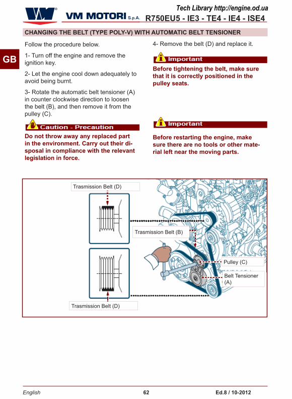
R750EU5 - IE3 - TE4 - IE4 - ISE4
English 62 Ed.8 / �0-20�2
GB
Do not throw away any replaced part in the environment. Carry out their di-sposal in compliance with the relevant legislation in force.
CHANGING THE BELT (TYPE PoLY-V) WITH AUTomATIC BELT TENSIoNER
Pulley (C)
Belt Tensioner (A)
Trasmission Belt (D)
Trasmission Belt (B)
Trasmission Belt (D)
Follow the procedure below.
1- Turn off the engine and remove the ignition key.
2- Let the engine cool down adequately to avoid being burnt.
3- Rotate the automatic belt tensioner (A) in counter clockwise direction to loosen the belt (B), and then remove it from the pulley (C).
4- Remove the belt (D) and replace it.
Before tightening the belt, make sure that it is correctly positioned in the pulley seats.
Before restarting the engine, make sure there are no tools or other mate-rial left near the moving parts.
Tech Library http://engine.od.ua

R750EU5 - IE3 - TE4 - IE4 - ISE4
English 63 Ed.8 / �0-20�2
GB
CHANGING THE BELT (TYPE PoLY-V) WITH AUTomATIC BELT TENSIoNER
special tool (A)
tensioner (B)
locking bracket (C)
Trasmission Belt (D)
Trasmission Belt (D)
Special equipment must be used to replace the belt with linear turnbuckle. This operation must be performed by an authorised repair shop.
Follow the procedure below.
1- Turn off the engine and remove the ignition key.
2- Let the engine cool down adequately to avoid being burnt.
3 - Rotate the special tool (A) in any anti-clockwise direction so that the turnbuckle (B) becomes compressed (Photo 1).
4 - Insert the locking clamp (C) as shown in photo 2.
5 - Remove the belt (D).
6 - Install the new belt and position it as shown in photo 3.
7 - Rotate the special tool (A) in an anti-clockwise direction so that the turnbuckle (B) becomes compressed, and remove the locking clamp.
Before tightening the belt, make sure that it is correctly positioned in the pulley seats.
Photo 1
Photo 2
Photo 3
Tech Library http://engine.od.ua
R750EU5 - IE3 - TE4 - IE4 - ISE4
English 64 Ed.8 / �0-20�2
GB
ENGINE DISPoSALThis operation should be carried out by experienced operators, in compliance with the legislation in force concerning safety at the workplace. Do not throw away non biodegradable products and non ferrous components (rubber, PVC, resins, etc.).
While decommissioning the engine, divide all the components depending on their chemical composition and dispose of them accordingly.
Tech Library http://engine.od.ua