engineered conductor systems & components · 2016-09-22 · engineered conductor systems &...
TRANSCRIPT

A Fandstan Electric Company
EN
GIN
EER
ED
CO
ND
UC
TO
R S
YS
TEM
S &
CO
MPO
NEN
TS
The original Delta Star engineered crane conductor systems designed and manufactured by TransTech
ENGINEERED CONDUCTORSYSTEMS & COMPONENTSFor Electrification of Cranes, Hoists, Conveyors and Other Applications
The original Delta Star engineered crane conductor systems designed and manufactured by TransTech

Table of Contents
Section I - Insulators
Section II - Accessories
Section III - Collectors
Section IV - C-Bar
Section V - H-Bar
Section VI - V-Bar
Section VII - HV-Bar
Section VIII - HJ-Bar
Section IX - HC-Bar
Section X - Lec-Trol-Feed
Section XI - Transductor
Section XII - High Bay Reflector Bracket
Section XIII - Engineers Reference Material
Ta
bleof C
ontents

Insulators - Molded Features Molded fiberglass reinforced polyester insulators have found wide acceptance in industrial insulation systems because of their superior mechanical strength, toughness, excellent electrical characteristics even under high humidity conditions and good weatherability and corrosion resistance. These materials are thermosetting exhibiting high heat resistance, flame retardance, excellent mechanical and thermal shock resistance, track resistance, and will not shatter if dropped.
TransTech insulators are molded of premium grade polyester compounds which have been tested and recognized by Underwriters Laboratory.* The materials used in these insulators are designed for NEMA Class B insulation applications. The insulators are self-extinguishing per ASTM D635 with flame resistance of 153 seconds to ignition and 25 seconds burning per FTMS-S-406,2023.2.
All molded insulators are 100% inspected and hi-pot withstand tested up to 25 kV for 10 seconds.
Applications Recommended applications include bus and switch support, contact rail and wire supports, panel and switchboard insulators, or any application requiring combined structural support and electrical insulation.
References U.L. Material-Recognition Number E27875-E36714 Patended: U.S. No. 3,098,894
Insula
tors

I-2
Current Collector Components/Insulators
Insulators - Molded Polyester Fiberglass Mechanical and Electrical Properties Tensile Strength (Pounds) ........................................ 7,000
Cantilever Strength (Inch Pounds)................... 12,000
Compression Strength (Pounds)....................... 65,000
Torsional Strength (Ft. Pounds)..............................150+
Tracking Resistance (Arc, ASTM D495) (Sec.) ................................190
Flame Resistance (ASTM D635) .............................................. Self-Ext. (ASTM D757) (Inch/Min.) .......................... 0.264 (Federal Std. 406)...........................................129/54
Creep Distance (Inches) Plate to Plate ............................................... 1/4 + “H” Insert to insert........................................13/16 + “H”
Water Absorption (% in 24 hrs.) (ASTM D570) .......................................................0.28
Height Tolerance.........................................................+0.015
Maximum Service Temp., Continuous............300˚ F. Intermittent ....................................................400˚ F.
Hi-Pot Withstand Test (100%) — KV..........................25
Corrugated Insulators
H = Height 25/8 23/4 27/8 3 31/8 31/4 33/8
Average Flashover Strength — Dry (K.V., S.T.) 40 40 45 45 50 50 55
Average Dew Flashover Strength (K.V., S.T.) 19 19.5 20 20.5 21 21.5 22
Impulse (K.V., 1.5 x 40 WAVE) WS* 80 84 88 92 96 100 104
Weight — Lbs. 1.75 1.8 1.85 1.9 1.95 2.0 2.05
Material: Fiberglass reinforced polyester, electrical grade, corrosion resistant, red-poly standard grade #1. Color red. *ASA C29.1 — 1951 American Standard Test Method Electrical Power Insulators
Catalog Information
Tap Size UNC - 2B
“H” = Height - Inches
25/8 23/4 27/8 3 31/8 31/4 33/8
1/2 - 13 88677 106600 106589 106590 106591 106592 106593 5/8 - 11 88678 106601 106594 106348 106595 106596 105960 3/4 - 10 89791 106602 106597 106349 106598 106599 105961

I-3
Current Collector Components/Insulators
Insulators - Molded Red-Poly For Electrical Systems
Features Featuring an all new self-cleaning configuration,* TransTech’s new line of polyester fiberglass standoff insulators are offered in 69 standard size and shape varieties. All heights in either diameter also can be had with molded petticoat as illustrated. The petticoat will double the creepage distance and wet-flashover value. The flame retardance and track resistance ability of RED-POLY Insulators, plus the mechanical strength to withstand high shock and vibration, allow almost unrestricted application within the rated voltage.
The wide range of stock sizes and shapes enable the electrical system designer to use standard insulators for almost any space problem encountered. However, for special space problems, TransTech can supply insulators to exact heights required at a very small extra cost. Economical product of “specials” is a result of uniquely flexible and advanced manufacturing processes.
Material Grade TransTech’s Material Grades are engineered for use as structural insulating members in equipment designed to meet NEMA Class B Requirements.
Each item as catalogued is made of electrical grade corrosion and track resistant fiberglass reinforced polyester. This is a high strength material with superior weather-resistant characteristics.
Petticoats The Petticoat provides a “Leakage Current Barrier” by effectively increasing the leakage distance, and is desirable for applications under conditions of excessive moisture, air contamination, etc.
Petticoat is available, as an integral part of any insulator size listed (See Ordering Directions).
Inserts All inserts are corrosion resistant plated steel with NC-class 2 threads.
*Patent No. 3,098,894

I-4
Current Collector Components/Insulators
Insulators - Molded Red-Poly For Electrical Systems
Catalog Number — 2” Dia.
Tap Size “H” Dim 11/2 15/8 13/4 17/8 2 21/8 21/4 23/8 21/2
1/4 - 20 9455101 9455102 9455103 9455104 9455105 9455106 9455107 5/16 - 18 9455108 9455109 9455110 9455111 9455112 9455113 9455114 3/8 - 16 9455115 9455116 9455117 9455118 9455119 9455120 9455121 9455122 9455123 1/2 - 13 9455124 9455125 9455126 9455127 9455128 9455129 9455130 5/8 - 11 9455131 9455132 9455133 9455134 9455135 9455136 9455137
Ordering Directions 1. To Order insulators with Petticoat, change 51 to 71 in Cat. No.
Average Mechanical and Electrical Properties Ultimate Tensile Strength (Pounds) Track Resistance, Inclined Plane D2303 (Min.).................1,200
11/2” to 17/8” High................................................................2,300 Arc Resistance (Arc, ASTM, D-495) (Sec)..................................190 2” to 21/2” High.....................................................................3,500 Flame Resistance (ASTM, D-635)........................................Self. Ext.
Ultimate Cantilever Strength (Inch-Pounds) Creep Distance (Inches - without Petticoat).................. 1/4 + H 11/2” to 17/8” High................................................................1,700 (Inches - with Petticoat)............................................................13/8 + H 2” to 21/2” High.....................................................................3,000 Water Absorption (% in 24 Hours) (ASTM, D-570)............0.28
Ultimate Compression Strength (Pounds)...................... 20,000 Height Tolerance (Inches)...........................................................+ .015 Ultimate Torsional Strength (Ft-Pounds)....................................50
H = Height 11/2 15/8 13/4 17/8 2 21/8 21/4 23/8 21/2
Flashover Strength - Dry (K.V., S.T.) 35 35 35 35 38 38 38 38 38 *Dew Flashover Strength (K.V., S.T.) w/o Petticoat 12 12.5 13 13.5 14 14.5 15 15.5 16 *Dew Flashover Strength (K.V., S.T.) w/ Petticoat 19 19.5 20 20.5 21 21.5 22 22.5 23 *Impulse (K.V., 1.5 x 40 WAVE) WS 25 30 35 40 45 50 55 60 65 Weight (lbs.) plus .15 lb. for Petticoat .22 .26 .30 .34 .38 .42 .46 .50 .54 *A.S.A. C29.1 — 1961 American Standard Test Method Electrical Power Insulators
Catalog Number — 25/8” Dia. Tap Size “H” Dim
25/8 23/4 27/8 3 31/8 31/4 33/8 31/2 3/8 - 16 9456101 9456102 9456103 9456104 9456105 9456106 9456107 9456108 1/2 - 13 9456109 9456110 9456111 9456112 9456113 9456114 9456115 9456116 5/8 - 11 9456117 9456118 9456119 9456120 9456121 9456122 9456123 9456124 3/4 - 10 9456125 9456126 9456127 9456128 9456129 9456130 9456131 9456132
Ordering Directions 1. To Order insulators with Petticoat, change 61 to 81 in Cat. No.
Average Mechanical and Electrical Properties Ultimate Tensile Strength (Pounds) ......................................5,000 Flame Resistance (ASTM, D-635)........................................Self. Ext. Ultimate Cantilever Strength (Inch-Pounds) ...................4,500 Leakage Distance (Inches - without Petticoat) ............ 3/8 + H Ultimate Compression Strength (Pounds)...................... 28,000 (Inches - with Petticoat)............................................................23/8 + H Ultimate Torsional Strength (Ft-Pounds).................................150 Water Absorption (% in 24 Hours) (ASTM, D-570)............0.28 Track Resistance, Inclined Plane D2303 (Min.).................1,200 Height Tolerance (Inches)...........................................................+ .015 Arc Resistance (Arc, ASTM, D-495) (Sec)..................................190
H = Height 25/8 23/4 27/8 3 31/8 31/4 33/8 31/2
17.5Flashover Strength - Dry (K.V., S.T.) 40 40 40 40 40 40 40 4017 *Dew Flashover Strength (K.V., S.T.) w/o Petticoat 17 17.5 18 18.5 19 19.5 20 20.5 *Dew Flashover Strength (K.V., S.T.) w/ Petticoat 28 28.5 29 29.5 30 30.5 31 31.5 *Impulse (K.V., 1.5 x 40 WAVE) WS 70 74 78 82 86 90 94 98 Weight (lbs.) plus .43 lb. for Petticoat .65 .70 .75 .80 .85 .90 .95 1.00 *A.S.A. C29.1 — 1961 American Standard Test Method Electrical Power Insulators

I-5
Current Collector Components/Insulators
Insulators - Molded Polyester Fiberglass Mechanical and Electrical Properties Tensile Strength (Pounds) ........................................ 7,000
Cantilever Strength (Inch Pounds)................... 12,000
Compression Strength (Pounds)....................... 65,000
Torsional Strength (Ft. Pounds)..............................150+
Tracking Resistance (Arc, ASTM D495) (Sec.) ................................190
Flame Resistance (ASTM D635)....................... Self-Ext.
Creep Distance (Inches) ................................... 21/8 + “H”
Water Absorption (% in 24 hrs.) (ASTM D570) .......................................................0.28
Height Tolerance.........................................................+0.015
Maximum Service Temp., Continuous............300º F. Intermittent .................................................. 400º F.
H = Height 25/8 23/4 27/8 3 31/8 31/4 33/8 31/2
Dielectric Strength — Dry (K.V., S.T.) 40 40 45 45 50 50 55 55
Dew Flashover Strength (K.V., S.T.)* 31 32 33 34 35 36 37 38
Impulse (K.V., 1.5 x 40 WAVE) WS* 90 94 98 102 106 110 114 118
Weight — Lbs. 2.3 2.4 2.5 2.6 2.7 2.8 2.9 3.0
Material: Fiberglass reinforced polyester, electrical grade, corrosion resistant, red-poly standard grade #1. Color red. *ASA C29.1 — 1951 American Standard Test Method Electrical Power Insulators
Catalog Information
Tap Size UNC - 2B
“H” = Height - Inches
25/8 23/4 27/8 3 31/8 31/4 33/8 31/2
1/2 - 13 99600-1 99600-4 105956-1 105956-4 105957-1 105957-4 105958-1 105958-4 5/8 - 11 99600-2 99600-5 105956-2 105956-5 105957-2 105957-5 105958-2 105958-5 3/4 - 10 99600-3 99600-6 105956-3 105956-6 105957-3 105957-6 105958-3 105958-6

I-6
Current Collector Components/Insulators
Insulators - Molded Giant Strain Application Giant Strain Insulator is a small rugged insulator. Its small size and high strength makes it suitable for many industrial applications. When equipped with the proper fittings it is used to support conductor angles, tee sections and bars; also when equipped with suitable hardware and clamps they are used for numerous strain applications, such as dead-ending trolley conductor wires or for supporting cables.
Features Giant Strain Insulators consist of two metal inserts molded in fiberglass reinforced polyester compound of high mechanical and electrical strength. One of the inserts is a cup shaped and the other is machined steel. When assembled they provide an interlocking design of high strength with the compound under compression rather than tensile loading. Relatively large mounting surface for such small insulators provides a substantial bearing for moderate cantilever loads.
Inserts are blind tapped to prevent them from being jacked loose as attaching cap screws are tightened. They are plated for corrosion resistance. Depth of tap is equal to or greater than the diameter.
The 21/4” diameter insulator is available with 1/2” threads and 5/8” threads. They are provided in two styles, the type E having 2 tapped bosses and the type W with one tapped boss and one short threaded stud.

I-7
Current Collector Components/Insulators
Insulators - Molded Giant Strain
1/2” Series 5/8” Series
Catalog Information
Insulator Type
Electrical Characteristics Mechanical Characteristics Maximum Service Temp
Degrees F. †
Net Weight
Lbs.
Catalog Number
Flashover Wet KV.
Dielectric Strength
Dry
Leakage Distance
Inches
Tensile Strength
Lbs.
Cantilever Strength
in Lbs.
Compression Strength
Lbs. 1/2” Series
E 10 20 3 12,000 6,500 30,000 250 3/4 93704
W 10 20 3 12,000 6,500 30,000 250 3/4 93703
F 10 20 3 12,000 6,500 30,000 250 .84 93705
G 10 20 3 12,000 6,500 30,000 250 1.41 93701
J 10 20 3 12,000 6,500 30,000 250 1.16 93700 5/8” Series
E 10 20 3 15,000 6,500 30,000 250 7/8 45784
W 10 20 3 15,000 6,500 30,000 250 1 67973
F 10 20 3 15,000 6,500 30,000 250 1.08 51911
G 10 20 3 15,000 6,500 30,000 250 2.06 45792
J 10 20 3 15,000 6,500 30,000 250 1.58 82369
† Reduce mechanical values 50% when maximum service temperature is required.
Ordering Directions - Specify by Catalog Number, type and size.

I-8
Current Collector Components/Insulators
Insulators - Porcelain Corrugated & Petticoat with Inserts
Application These porcelain insulators are designed for general insulating purposes either indoors or outdoors, particularly where subject to moisture or industrial contaminants. They are suitable for supporting heavy overrunning rails. Other uses are for insulating resistors, bus bars, collectors, critical control conductors or similar industrial application.
Features These insulators are made of a wet process porcelain body provided with corrugations or extra heavy petticoats to resist breakage and provide maximum leakage distance. Plated iron inserts are bonded into the insulators by means of a special process providing resistance to vibration. Inserts are blind tapped to prevent them from becoming jacked loose as attaching cap screws are tightened. Depth of gap is equal to or greater than the thread diameter
References Assemblies using these insulators with proper rail clamps and bases can be used to support overrunning contact rails. When corrugated insulators are mounted horizontally to support light conductor angles, the expansion stud fitting listed on page II-11 should be used to allow movement of the conductor rail due to expansion.
Additional designs of petticoat insulators with various styles of mountings bonded thereon are available.
Catalog Information Dimensions Electrical Characteristics Mechanical Characteristics
Maximum Service Temp
Degrees F.
Net Weight
Lbs.
Catalog NumberA B D
UNC-2B
Avg. Flashover Leakage Distance
Inches
Tensile Strength
Lbs.
Cantilever Strength
in Lbs.
Compression Strength
Lbs. Dry Kv. Wet Kv.
Corrugated Insulators 31/2 33/4
5/8 - 11 46 17 4 5000 7500 51000 300 31/2 49874 25/8 3 1/2 - 13 40 16 3 3000 5000 28000 300 15/8 59690 25/8 4 5/8 - 11 40 16 31/4 3800 5000 37000 300 33/8 59695 25/8 3 5/8 - 11 40 16 3 3000 5000 28000 300 15/8 112168 33/8 43/4
3/4 - 10 44 17 41/16 5000 8300 77000 300 53/4 69265 33/8 6 1 - 8 44 17 51/16 5000 8300 100000 300 111/4 74283
Petticoat Insulators 25/8 415/16
1/2 - 13 50 20 6.2 3000 4200 25000 300 23/4 64658 25/8 415/16
5/8 - 11 50 20 6.2 3000 4200 25000 300 23/4 64672 31/2 51/2
1/2 - 13 65 29 6.5 3500 6000 30000 300 51/4 90638 31/2 51/2
5/8 - 11 65 29 6.5 3500 6000 30000 300 51/4 91376 31/2 51/2
3/4 - 10 65 29 6.5 3500 6000 30000 300 51/4 91694 4 7 1/2 - 13 75 38 9.1 5000 7700 60000 300 73/4 93968 4 7 5/8 - 11 75 38 9.1 5000 7700 60000 300 73/4 97703 4 7 3/4 - 10 75 38 9.1 5000 7700 60000 300 73/4 97704
† Reduce mechanical values 50% when maximum service temperature is required.
Ordering Directions - Specify by Catalog Number.

I-9
Current Collector Components/Insulators
Insulators - Porcelain Petticoat with Mountings Features These insulator assemblies are similar in design to the petticoat insulators shown on the preceding page except they are provided with plated iron mounting bases and caps for particular requirements. Depth of tap is equal to or greater than the diameter.
References Wire clamps to support trolley wire conductors with these insulators and other accessories for supporting rigid conductors may be selected.
Catalog Information
Insulator Type
Electrical Characteristics Mechanical Characteristics Maximum
Service Temp Degrees F.
Net Weight
Lbs.
Catalog Number
Flashover Wet KV.
Dielectric Strength
Dry
Leakage Distance
Inches
Tensile Strength
Lbs.
Cantilever Strength
in Lbs.
Compression Strength
Lbs. 1/2 - 13 85 55 15.5 10000 21000 40000 300 271/4 90990 5/8 - 11 85 55 15.5 10000 21000 40000 300 271/4 91409
— 85 55 15.5 10000 21000 40000 300 301/4 91041 1/2 - 13 50 25 6.3 4000 6600 40000 300 91/2 91151 5/8 - 11 50 25 6.3 4000 6600 40000 300 91/2 98298 1/2 - 13 50 25 6.3 4000 5800 40000 300 71/2 91378 5/8 - 11 50 25 6.3 4000 5800 40000 300 71/2 92251 1/2 - 13 50 25 6.3 4000 5800 40000 300 71/2 92252 5/8 - 11 50 25 6.3 4000 5800 40000 300 71/2 92685
Ordering Directions - Specify by Catalog Number, type and size.

I-10
Current Collector Components/Insulators
Insulators - Porcelain Giant Strain Application Porcelain covered Giant Strain insulators are designed for general use where high values of tensile strength are required in outside applications or in atmospheres which make the superior qualities of wet process porcelain desirable. These units provide the strength, compactness, and reliability of the Giant Strain insulator with the water-proofing and non-arc tracking characteristics of wet-process porcelain. They are suitable for supporting heavy loadings in tension or compression in combination with vibration and shock. They are used for rugged strain and support applications, including suspension of heavy conductor rail sections for ore bridge and unloader installations.
Features Porcelain covered Giant Strain insulators consist of a standard fiberglass reinforced polyester insulating strain unit which is sealed into a brown glazed wet-process jacket with a new improved epoxy resin-polysulfide rubber compound. Inner strain unit uses inter-locking steel members designed to transpose a high tensile loading into compressive reaction which can be safely accommodated by central restrained fiberglass reinforced polyester insulating sections. This feature provides extra protection against release of the load if severe overstress occurs.
Outer seal is resilient throughout extreme changes in temperature and chemical exposure, and thereby affords extra protection against breakage of the porcelain jacket. The jacket is so effectively bonded to the inner member that portions of the jacket, if broken, remain attached to the seal providing for the ultimate in safety to personnel. Quality of bond obtained in the seal assures maintenance of the original electrical striking distance despite long exposure to the elements. All fittings are plated.
Reference See insulator assembly section for assemblies complete with eyes and clevises or with rail support fittings.
Catalog Information
Max/. System voltage
AC or DC
Electrical Characteristics Mechanical Characteristics Service
Temp De-grees F.
Net Weight
Lbs.
Catalog Number
Dielectric Strength Dry Kv.
Wet Flash-
over Kv.
Leakage Distance
Inches
Tensile Strength
Lbs.
Cantilever Strength
in Lbs.
Compression Strength
Lbs.
Insert Rotation
Resistance Ft. Lbs
1000 20 10 43/4 12000 4200 40000 50 - 30˚ to 200˚ 2 62436
Ordering Directions - Specify by Catalog Number.

I-11
Current Collector Components/Insulators
Insulators - Molded Giant Strain Type Application Giant strain insulators with suitable hardware are used to support electrical cables such as feeder lines in industrial plants, for dead ending wire used as conductors and similar applications.
Features Assemblies listed in detail on the following pages, some of which are shown below, are assembled from the following major components.
1/2” Series Component 5/8” Series
93703 Insulator with Stud & Boss 67973
93194 Strain Eye 89149
63449 Strain Clevis 90092
75525 Short Stud 94635
90668 Long Stud 90669
76081 Extra Long Stud 76270
Typical Assemblies
93851
93853
94704
31389
94706
46281
1/2” Series 5/8” Series
U.S. Patent #2,967,903

I-12
Current Collector Components/Insulators
Insulators - Molded 1/2” Strain Insulators
Catalog Information Description Standard Package Net Wt. Each — Lbs. Catalog No.
with Two eyes 25 1.38 93850
with Strain Clevis & Eye 25 1.41 93851
with Two Strain Clevises 25 1.44 93852
with Eye and Tapped Boss 25 1.06 93853
with Eye and Long Stud — A-21/2” — B-61/4” 25 1.41 93854
with Eye and Extra Long Stud — A-6” — B-93/4” 20 1.56 93856
with Strain Clevis and Tapped Boss 25 1.09 94642
with Strain Clevis and Long Stud — A-21/2” — B-613/32” 25 1.44 94669
with Strain Clevis and Extra Long Stud — A-6” — B-929/32” 20 1.59 94704
Dimensions 2” Diameter Insulators 750 Volt-Maximum Service 5600# Safe Working Load
93850
93851
93852
94642
93856 93854
94669 94704
93853
Ordering Directions - Specify by Catalog Number.

I-13
Current Collector Components/Insulators
Insulators - Molded 5/8” Strain Insulators
Catalog Information Description Standard Package Net Wt. Each — Lbs. Catalog No.
with Two eyes 25 2.00 31336
with Strain Clevis & Eye 25 2.25 31389
with Two Strain Clevises 25 2.50 31393
with Eye and Tapped Boss 25 1.46 45780
with Eye and Long Stud — A-21/2” — B-619/32” 25 2.16 45788
with Eye and Extra Long Stud — A-7” — B-113/32” 25 2.35 46281
with Strain Clevis and Tapped Boss 25 1.69 94706
with Strain Clevis and Long Stud — A-21/2” — B-629/32” 25 2.27 94707
with Strain Clevis and Extra Long Stud — A-7” — B-1113/32” 12 2.58 82030
Dimensions 21/4” Diameter Insulators 750 Volt-Maximum Service 9,000# Safe Working Load
31336
Ordering Directions - Specify by Catalog Number.
45780
31389
45788 46281
94706
31393
94707 82030

I-14
Current Collector Components/Insulators
Insulators - Molded Porcelain Covered Giant Strain Insulators
Application Porcelain covered Giant Strain insulators are designed for general use where high values of tensile strength are required in outside applications as in atmospheres which make the superior qualities of wet process porcelain desirable.
These units provide the strength, compactness, and reliability of the Giant Strain insulator with the water-proofing and non-arc tracking characteristics of wet-process porcelain.
They are suitable for supporting heavy loadings in tension in combination with vibration and shock. They are used for rugged strain applications.
Features Porcelain covered Giant Strain insulators consist of a polyester strain insulator which is sealed into a brown glazed wet-process jacket with a new improved epoxy resin-polysulfide rubber compound. Inner strain unit uses inter-locking steel members designed to transpose a high tensile loading into compressive reaction which can be safely accommodated by central restrained polyester insulating sections. This feature provides extra protection against release of the load if severe overstress occurs.
Outer seal is resilient throughout extreme changes in temperature and chemical exposure, and thereby affords extra protection against breakage of the porcelain jacket. Jacket is so effectively bonded to the inner member, that portions of the jacket, if broken, remain attached to the seal providing for ultimate in safety to personnel. Quality of bond obtained in the seal assures maintenance of the original electrical striking distance despite long exposure to the elements.
All fittings are malleable, zinc plated, and are mounted on 5/8” diameter zinc plated studs.
Strain Type 61348
Strain Type 61349
Strain Type 61350
Catalog Number
Description
Electrical Characteristics Mechanical Characteristics Maximum
Service Temp.
Degrees F˚
Net Wt. Each Lbs.
Catalog NumberFlashover
Wet Kv.
Dry Dielectric
KV.
Leakage Distance
Inches
Max. Sys. Voltage
AC or DC V.
Tensile Strength
Lbs.
Insert Rotation
Resistance Ft. Lbs.
with two eyes 10 20 43/4 1000 10000 50 200 2.95 61348
with two clevises 10 20 43/4 1000 10000 50 200 3.40 61349
with eye and clevises 10 20 43/4 1000 10000 50 200 3.20 61350
Ordering Directions - Specify by Catalog Number.

I-15
Current Collector Components/Insulators
Insulators - Molded Spool & Bracket Application Spool insulators are used for supporting trolley wire conductors in a “pick-up” type system supplying current to electric cranes. Collectors attached to the cranes make contact by picking up the conductor wires which are supported on these spool and bracket type insulators.
Features Spool insulators are made from red molded composition. Bracket insulator is made from brown glazed porcelain.
The molded composition spool insulator has greater mechanical strength than the porcelain spool. Wire grooves are wide and deep to provide considerable movement of the conductor wire. Composition spool insulator with bolt differs from the others in that it is provided with a 1/2 inch diameter bolt permanently molded therein and supplied with a nut and washer minimizing the possibility of spools working loose due to vibration.
Molded Composition Type
45501
47226
45553
Catalog Information Description Approx. Wt. Lbs. Catalog No.
Composition Spool Insulator .56 45501
Composition Spool Insulator 1.25 45553
Composition Spool Insulator with Bolt .56 47226
Porcelain Bracket Insulator 1.25 46230
Ordering Directions - Specify by Catalog Number.
46230

I-16
Current Collector Components/Insulators
Insulators - Molded Suspension Type
Application The suspension insulators shown on this page are rugged insulators intended for use with suitable accessories to support crane runway conductors such as wire, bars, tees and angles.
Features Bodies of all suspension insulators are galvanized malleable iron castings. A “Parkerized” finished steel 5/8-11 threaded stud insert with integral bearing surface is molded into the body of each with a thermo-setting insulating compound molded to form generous petticoats.
There are two sizes, the larger type K with a body diameter of 35/8” and consequently a greater leakage distance between the stud and the body. Smaller type F insulator having a shorter leakage distance is used where space conditions are limited and where moisture and industrial contaminants permit.
Type T4 insulator is like the type F4 with mounting holes in a horizontal plane and with minimum extension from mounting surface. When selecting accessories to be used with these insulators make certain to provide adequate clearance to mounting surfaces.
References With suitable hardware and accessories, these insulators can be used for supporting wire and rigid conductors.
No. 30876 type K2 insu-lators are for attach-ment to a horizontal surface.
No. 30880 type K4 insulators are de-signed for attachment to a vertical surface. This insulator will accommodate trolley wire clamps up to and including 5” long .
No. 41384 type K8 insulators are a universal form, adaptable to varied mountings; such as pipe suspension fittings, or bolts.

I-17
Current Collector Components/Insulators
Insulators - Molded Suspension Type Types F & T
No. 44608 type F2 Insulators are for attachment to a horizontal surface
No. 44448 type F8 insulators are a universal form, adaptable to varied mountings; such as pipe suspension fittings, or bolts.
No. 49692 type F4 insulators are designed for attachment to a vertical surface. This insulator will accommodate trolley wire clamps up to and including 5” long.
No. 90766 type 14 insulators are designed for attachment to a vertical surface. Mounting holes are in a horizontal plane and with minimum extension from the mounting surface.
Catalog Number
Type
Electrical Characteristics Mechanical Characteristics †Maximum Service Temp.
Degrees F˚
Net Wt. Lbs.
Catalog NumberDry Flashover
Kv. Wet Flashover
KV.
Leakage Distance
Inches
Tensile Strength
Lbs.
Cantilever Strength In — Lbs.
K2 20 14 2.3 15000 6500 250 2.62 30876
K4 20 14 2.3 15000 6500 250 2.82 30880
K8 20 14 2.3 15000 6500 250 2.68 41384
F2 15 6 .94 12000 5000 250 1.31 44608
F4 15 6 .94 12000 5000 250 1.94 49692
F8 15 6 .94 12000 5000 250 1,50 44448
T4 15 6 .94 12000 5000 250 1.43 90766
† Reduce mechanical value 50% when maximum service temperature is required.
Ordering Directions - Specify by Catalog Number.

I-18
Current Collector Components/Insulators
Insulators - Assemblies Overrunning Conductors, Contact Rail B Series
Application These insulators are designed for supporting conventional ASCE rail sections when used as contact rail conductors when collectors are operating in an over-running position.
Features These designs consist of a bolted assembly of various types of insulators plus mounting bases and rail supports. All types are provided with interlocking notched clamps adjustable to accommodate different rail sizes and permit horizontal alignment. Clamps are designed to permit free movement of the conductor rail to allow for expansion due to temperature changes. Insulator assemblies can be used on circuits up to 5KV. For detailed electrical and mechanical characteristics of the individual insulators see Insulator section of catalog. Assemblies are listed both with and without mounting bases to suit the particular installation requirements. Mounting bases are supplied with slots to accommodate 1/2” mounting bolts except assemblies using 6” diameter corrugated porcelain insulators where 5/8” mounting bolts are used. On assemblies without bases the T dimension or thickness of mounting surface must be specified to determine length of bolt.
Corrugated Porcelain Polyester Fiberglass Petticoat Porcelain Petticoat Polyester Insulator Assembly Insulator Assembly Insulator Assembly Fiberglass
Insulator Assembly

I-19
Current Collector Components/Insulators
Insulator Assemblies Overrunning Conductors Contact Rail B Series
Figure 1With Corrugated
Porcelain Insulators
Figure 2With 64672 Petticoat
Porcelain Insulator
Figure 3With 91376 and 91694
Petticoat Porcelain Insulator
Porcelain Rail Supports Without Mounting BaseWith Corrugated Porcelain Insulator Units
Rail Sizes Lbs. per Yd.
A.S.C.E.
Insulator Number
Figure Number
Insulator Diameter
D
Dimensions in Inches Cantilever Strength Inch Lbs.
Net Weight Lbs.
CatalogNumberA H K
12 to 30 63326 1 3” 5” 35/8” 5/8” - 11 4350 4.25 59667
12 to 30 49874 1 31/4” 5” 41/2” 5/8” - 11 6750 5.75 64110
12 to 30 59695 1 4” 5” 35/8” 5/8” - 11 4350 5.00 59671
12 to 30 69265 1 43/4” 5” 43/8” 3/4” - 10 7450 8.25 99913
35 to 60 49874 1 33/4” 61/4” 41/2” 5/8” - 11 6750 6.50 64112
35 to 60 59695 1 4” 61/4” 35/8” 5/8” - 11 4350 6.00 59673
35 to 60 69265 1 43/4” 61/4” 43/8” 3/4” - 10 7450 8.75 69249
50 to 100 59695 1 4” 8” 35/8” 5/8” - 11 4350 8.00 99911
60 to 100 69265 1 43/4” 8” 43/8” 3/4” - 10 7450 10.00 69250
60 to 100 74283 1 6” 8” 43/8” 1” - 8 7450 11.50 76630
70 to 100 74283 1 6” 8” 43/8” 1” - 8 7450 13.00 99920
70 to 100 59695 1 4” 8” 35/8” 5/8” 4350 7.00 99912
110 to 152 74283 1 6” 91/2” 43/8” 1” 7450 13.00 74269
Porcelain Rail Supports Without Mounting BaseWith Porcelain Petticoat Insulator Units
12 to 30 64672 2 415/16” 5” 35/8” 5/8” - 11 1000 5.00 98968
35 to 60 91376 3 51/2” 61/4” 41/2” 5/8” - 11 1200 8.25 98969
65 to 100 91694 3 51/2” 8” 41/2” 3/4” - 10 1200 9.50 98970 Note: When ordering specify “T” dimension to insure proper bolt length

I-20
Current Collector Components/Insulators
Polyester Fiberglass Rail Supports Without Mounting BaseWith Corrugated Polyester Fiberglass Insulator
Rail Sizes Lbs. per Yd.
A.S.C.E.
Insulator Number
Figure Number
Insulator Diameter
D
Dimensions in Inches Cantilever Strength Inch Lbs.
Net Weight
Lbs.
CatalogNumberA H K*
12 to 30 88678 1 3” 5” 35/8” 5/8” - 11 7975 4.00 91794
12 to 30 106601 1 3” 5” 33/4” 5/8” - 11 8250 4.07 106675
12 to 30 106594 1 3” 5” 37/8” 5/8” - 11 8525 4.14 106676
12 to 30 106348 1 3” 5” 4” 5/8” - 11 8800 4.21 106351
12 to 30 105695 1 3” 5” 41/8” 5/8” - 11 9075 4.28 106677
12 to 30 106596 1 3” 5” 41/4” 5/8” - 11 9350 4.35 106678
12 to 30 105960 1 3” 5” 43/8” 5/8” - 11 9650 4.42 106352
35 to 60 88678 1 3” 61/4” 35/8” 5/8” - 11 7975 4.75 91795
35 to 60 106601 1 3” 61/4” 33/4” 5/8” - 11 8250 4.82 106679
35 to 60 106594 1 3” 61/4” 37/8” 5/8” - 11 8525 4.89 106680
35 to 60 106348 1 3” 61/4” 4” 5/8” - 11 8800 4.96 106353
35 to 60 106595 1 3” 61/4” 41/8” 5/8” - 11 9075 5.03 106681
35 to 60 106596 1 3” 61/4” 41/4” 5/8” - 11 9350 5.10 106682
35 to 60 105960 1 3” 61/4” 43/8” 5/8” - 11 9650 5.17 106354
65 to 100 88678 1 3” 8” 35/8” 5/8” - 11 7975 5.00 106350
65 to 100 106601 1 3” 8” 33/4” 5/8” - 11 8250 5.07 106683
65 to 100 106594 1 3” 8” 37/8” 5/8” - 11 8525 5.14 106684
65 to 100 106348 1 3” 8” 4” 5/8” - 11 8800 5.21 106373
65 to 100 106595 1 3” 8” 41/8” 5/8” - 11 9075 5.28 106685
65 to 100 106596 1 3” 8” 41/4” 5/8” - 11 9350 5.35 106686
65 to 100 105960 1 3” 8” 43/8” 5/8” - 11 9650 5.42 106374
* Assemblies available with 1/2 -13 or 3/4 - 10 inserts upon request.Note: When ordering specify “T” dimension to insure proper bolt length
Insulator Assemblies Overrunning Conductors Contact Rail B Series
Figure 1With Corrugated
Polyester Fiberglass Insulator

I-21
Current Collector Components/Insulators
Insulator Assemblies Overrunning Conductors Contact Rail B Series
Polyester Fiberglass Rail Supports Without Mounting BaseWith Petticoat Polyester Fiberglass Insulator
Rail Sizes Lbs. per Yd.
A.S.C.E.
Insulator Number
Figure Number
Insulator Diameter
D
Dimensions in Inches Cantilever Strength Inch Lbs.
Net Weight
Each Lbs.
CatalogNumberA H K*
12 to 30 99600-2 1 5” 5” 35/8” 5/8” - 11 4350 4.75 99967
12 to 30 99600-5 1 5” 5” 33/4” 5/8” - 11 4500 4.81 106645
12 to 30 105956-2 1 5” 5” 37/8” 5/8” - 11 4650 4.87 106646
12 to 30 105956-5 1 5” 5” 4” 5/8” - 11 4800 4.93 106335
12 to 30 105957-2 1 5” 5” 41/8” 5/8” - 11 4950 4.99 106647
12 to 30 105957-5 1 5” 5” 41/4” 5/8” - 11 5100 5.05 106648
12 to 30 105958-2 1 5” 5” 43/8” 5/8” - 11 5250 5.11 106336
12 to 30 105958-5 1 5” 5” 41/2” 5/8” - 11 5400 5.17 106649
35 to 60 99600-2 1 5” 61/4” 35/8” 5/8” - 11 4350 5.40 99968
35 to 60 99600-5 1 5” 61/4” 33/4” 5/8” - 11 4500 5.46 106650
35 to 60 105956-2 1 5” 61/4” 37/8” 5/8” - 11 4650 5.52 106651
35 to 60 105956-5 1 5” 61/4” 4” 5/8” - 11 4800 5.58 106337
35 to 60 105957-2 1 5” 61/4” 41/8” 5/8” - 11 4950 5.64 106652
35 to 60 105957-5 1 5” 61/4” 41/4” 5/8” - 11 5100 5.70 106653
35 to 60 105958-2 1 5” 61/4” 43/8” 5/8” - 11 5250 5.76 106338
35 to 60 105958-5 1 5” 61/4” 41/2” 5/8” - 11 5400 5.82 106654
65 to 100 99600-2 1 5” 8” 35/8” 5/8” - 11 4350 6.10 99969
65 to 100 99600-5 1 5” 8” 33/4” 5/8” - 11 4500 6.16 106655
65 to 100 105956-2 1 5” 8” 37/8” 5/8” - 11 4650 6.22 106656
65 to 100 105956-5 1 5” 8” 4” 5/8” - 11 4800 6.28 106339
65 to 100 105957-2 1 5” 8” 41/8” 5/8” - 11 4950 6.34 106657
65 to 100 105957-5 1 5” 8” 41/4” 5/8” - 11 5100 6.40 106658
65 to 100 105958-2 1 5” 8” 43/8” 5/8” - 11 5250 6.46 106340
65 to 100 105958-5 1 5” 8” 41/2” 5/8” - 11 5400 6.52 106659
* Assemblies available with 1/2 -13 or 3/4 - 10 inserts upon request.Note: When ordering specify “T” dimension to insure proper bolt length
Figure 1With Petticoat
Polyester Fiberglass Insulator

I-22
Current Collector Components/Insulators
Insulator Assemblies Overrunning Conductors Contact Rail B Series
Figure 1With Corrugated
Porcelain Insulators
Figure 2With 64672 Petticoat
Porcelain Insulator
Figure 3With 91376 and 91694
Petticoat Porcelain Insulator
Porcelain Rail Supports With Mounting BaseWith Corrugated Porcelain Insulator Units
Rail Sizes Lbs. per Yd.
A.S.C.E.
Insulator Number
Figure Number
Insulator Diameter
D
Dimensions in Inches L Dimension Cantilever Strength Inch Lbs.
Net Weight
Lbs.
CatalogNumberA H Min. Max.
12 to 30 63326 1 3” 5” 41/2” 5” 61/4” 4350 5.12 64168
12 to 30 59695 1 4” 5” 41/2” 5” 61/4” 3750 8.25 59675
12 to 30 69265 1 43/4” 5” 51/4” 5” 61/4” 7450 10.00 72611
12 to 30 49874 1 33/4” 5” 53/8” 5” 61/4” 6750 8.75 64106
35 to 60 59695 1 4” 61/4” 41/2” 5” 61/4” 4350 9 59677
35 to 60 49874 1 33/4” 61/4” 53/8” 5” 61/4” 6750 9.5 64108
35 to 60 69265 1 43/4” 61/4” 51/4” 5” 61/4” 7450 11.75 72613
50 to 100 59695 1 4” 8” 41/2” 5” 61/4” 4350 12.25 99952
60 to 100 69265 1 43/4”” 8” 51/4” 5” 61/4” 7450 13 72615
60 to 100 74283 1 6” 8” 53/8” 73/4” 81/2” 7650 16.75 98972
110 to 152 74283 1 6” 91/2” 53/8” 73/4” 81/2” 7650 18.25 98973
Porcelain Rail Supports With Mounting BaseWith Porcelain Petticoat Insulator Units
12 to 30 64672 2 415/16” 5” 41/2” 5” 61/4” 1000 800 98977
35 to 60 91376 3 51/2” 61/4” 53/8” 5” 61/4” 1200 1125 98978
65 to 100 91694 3 51/2” 8” 53/8” 5” 61/4” 1200 1250 98979
Slots in Mounting Bases Accommodate 1/2” Bolts.Slots on 6” Diameter Corrugated Porcelain Assemblies Accommodate 5/8” Bolts.

I-23
Current Collector Components/Insulators
Insulator Assemblies Overrunning Conductors Contact Rail B Series
Polyester Fiberglass Rail Supports With Mounting BaseWith Corrugated Polyester Fiberglass Insulator
Rail Sizes Lbs. per Yd.
A.S.C.E.
Insulator Number
Figure Number
Insulator Diameter
D
Dimensions in Inches L Dimension Cantilever Strength Inch Lbs.
Net Weight
Lbs.
CatalogNumberA H Min. Max.
12 to 30 88678 1 3” 5” 41/2” 5” 61/4” 7975 5.75 95377
12 to 30 106601 1 3” 5” 45/8” 5” 61/4” 8250 5.82 106687
12 to 30 106594 1 3” 5” 43/4” 5” 61/4” 8525 5.89 106688
12 to 30 106348 1 3” 5” 47/8” 5” 61/4” 8800 5.96 106355
12 to 30 105695 1 3” 5” 5” 5” 61/4” 9075 6.03 106689
12 to 30 106596 1 3” 5” 51/8” 5” 61/4” 9350 6.10 106690
12 to 30 105960 1 3” 5” 51/4” 5” 61/4” 9650 6.17 106356
35 to 60 88678 1 3” 61/4” 41/2” 5” 61/4” 7975 6.75 90960
35 to 60 106601 1 3” 61/4” 45/8” 5” 61/4” 8250 6.82 106691
35 to 60 106594 1 3” 61/4” 43/4” 5” 61/4” 8525 6.89 106692
35 to 60 106348 1 3” 61/4” 47/8” 5” 61/4” 8800 6.96 106357
35 to 60 105695 1 3” 61/4” 5” 5” 61/4” 9075 7.03 106693
35 to 60 106596 1 3” 61/4” 51/8” 5” 61/4” 9350 7.10 106694
35 to 60 105960 1 3” 61/4” 51/4” 5” 61/4” 9650 7.17 106358
65 to 100 88678 1 3” 8” 41/2” 5” 61/4” 7975 7.75 106359
65 to 100 106601 1 3” 8” 45/8” 5” 61/4” 8250 7.82 106695
65 to 100 106594 1 3” 8” 43/4” 5” 61/4” 8525 7.89 106696
65 to 100 106348 1 3” 8” 47/8” 5” 61/4” 8800 7.96 106360
65 to 100 105695 1 3” 8” 5” 5” 61/4” 9075 8.03 106697
65 to 100 106596 1 3” 8” 51/8” 5” 61/4” 9350 8.10 106698
65 to 100 105960 1 3” 8” 51/4” 5” 61/4” 9650 8.17 106361
Slots in mounting base accommodate 1/2” bolts
Figure 1With Corrugated
Polyester Fiberglass Insulator

I-24
Current Collector Components/Insulators
Insulator Assemblies Overrunning Conductors Contact Rail B Series
Polyester Fiberglass Rail Supports With Mounting BaseWith Petticoat Polyester Fiberglass Insulator
Rail Sizes Lbs. per Yd.
A.S.C.E.
Insulator Number
Figure Number
Insulator Diameter
D
Dimensions in Inches L Dimension Cantilever Strength Inch Lbs.
Net Weight
Each Lbs.
CatalogNumberA H Min. Max.
12 to 30 99600-2 1 5” 5” 41/2” 5” 61/4” 4350 6.5 99970
12 to 30 99600-5 1 5” 5” 45/8” 5” 61/4” 4500 6.56 106660
12 to 30 105956-2 1 5” 5” 43/4” 5” 61/4” 4650 6.62 106661
12 to 30 105956-5 1 5” 5” 47/8” 5” 61/4” 4800 6.68 106341
12 to 30 105957-2 1 5” 5” 5” 5” 61/4” 4950 6.74 106662
12 to 30 105957-5 1 5” 5” 51/8” 5” 61/4” 5100 6.80 106663
12 to 30 105958-2 1 5” 5” 51/4” 5” 61/4” 5250 6.86 106342
12 to 30 105958-5 1 5” 5” 53/8” 5” 61/4” 5400 6.92 106664
35 to 60 99600-2 1 5” 61/4” 41/2” 5” 61/4” 4350 7.15 99971
35 to 60 99600-5 1 5” 61/4” 45/8” 5” 61/4” 4500 7.21 106665
35 to 60 105956-2 1 5” 61/4” 43/4” 5” 61/4” 4650 7.27 106666
35 to 60 105956-5 1 5” 61/4” 47/8” 5” 61/4” 4800 7.33 106343
35 to 60 105957-2 1 5” 61/4” 5” 5” 61/4” 4950 7.39 106667
35 to 60 105957-5 1 5” 61/4” 51/8” 5” 61/4” 5100 7.45 106668
35 to 60 105958-2 1 5” 61/4” 51/4” 5” 61/4” 5250 7.51 106344
35 to 60 105958-5 1 5” 61/4” 53/8” 5” 61/4” 5400 7.57 106669
65 to 100 99600-2 1 5” 8” 41/2” 5” 61/4” 4350 7.85 99972
65 to 100 99600-5 1 5” 8” 45/8” 5” 61/4” 4500 7.91 106670
65 to 100 105956-2 1 5” 8” 43/4” 5” 61/4” 4650 7.97 106671
65 to 100 105956-5 1 5” 8” 47/8” 5” 61/4” 4800 8.03 106345
65 to 100 105957-2 1 5” 8” 5” 5” 61/4” 4950 8.10 106672
65 to 100 105957-5 1 5” 8” 51/8” 5” 61/4” 5100 8.16 106673
65 to 100 105958-2 1 5” 8” 51/4” 5” 61/4” 5250 8.22 106346
65 to 100 105958-5 1 5” 8” 53/8” 5” 61/4” 5400 8.28 106674
Slots in mounting base accommodate 1/2” bolts
Figure 1With Petticoat
Polyester Fiberglass Insulator

I-25
Current Collector Components/Insulators
Insulators Assemblies Overrunning ConductorsTypes HA, BOA, DDI, and DD
ApplicationThese insulators are designed for supporting conventional ASCE rail sections when used as contact rail conductors when collectors are operating in an overrunning position.
These insulator assemblies differ from the “B” Series previously shown since the mounting bases and, in some cases, the rail supports are cemented to the insulators.
Four types most commonly used are shown, however, other types can also be supplied for various mountings and rail sizes.
Type “HA”
Type “BOA”
4869648697486984879060444
6304563670
Type “DDI”
Type “DD”
70463
4651946520

I-26
Current Collector Components/Insulators
Insulators AssembliesOverrunning Conductors - Types HA and BOA
Type HA Features
Design Insulator with cast base cemented therein.
Rail fittings are clamped to insulator making a rigid assembly.
Rail clamps permit free movement of rail to allow for expansion and contraction.
Insulator Square block of brown glazed dry process porcelain.
Metal Parts Galvanized
Catalog InformationFor ASCE Rail
Size Lbs. per Yd.Dimension A
InchesNet Wt.
Each — Lbs.Catalog Number
12 - 14 25/16 7 48696
16 2 5/8 7 48697
20 - 25 3 7 48698
30 3 3/8 7 48790
30 - 40 3 3/4 8 1/4 60444
Type BOA Features
Design Insulator with base and rail cap cemented thereto making one piece assembly except for rail lugs.
Rail clamps permit free movement of rail to allow for expansion and contraction.
High strength parts and assembly for use where unusual mechanical strength is required.
Insulator Petticoat design of brown glazed wet-process porcelain.
Metal Parts Galvanized
Catalog InformationFor ASCE Rail
Size Lbs. per Yd.Dimension A
InchesNet Wt.
Each — Lbs.Catalog Number
35 - 60 61/4 10 63045
65 - 100 8 12 63670
Ordering Directions - Specify by Catalog Number.

I-27
Current Collector Components/Insulators
Insulators AssembliesOverrunning Conductors - Types DDI and DD
Type DDI Features
Design Large rail mounting cap cemented to top of insulator.
Tapped insert cemented to bottom of insulator provides single hole mounting.
Rail clamps permit free movement of rail to allow for expansion and contraction.
Insulator Round block of brown glazed dry process porcelain.
Metal Parts Galvanized
Catalog InformationFor ASCE Rail Size
Lbs. per Yd.Net Wt.
Each — Lbs.Catalog Number
30 - 40 111/2 70463
Type DD Features
Design Large rail mounting cap cemented to top of insulator.
Four hole flat base cemented to bottom of insulator.
Rail clamps permit free movement of rail to allow for expansion and contraction.
Insulator Round block of brown glazed dry process porcelain.
Metal Parts Galvanized
Catalog InformationFor ASCE Rail Size
Lbs. per Yd.Net Wt.
Each — Lbs.Catalog Number
45 - 65 14 46519
70 - 95 14 46520
Ordering Directions - Specify by Catalog Number.

I-28
Current Collector Components/Insulators
Insulators Assemblies Underrunning ConductorsApplicationUnder-Contact Rail System illustrated is for supporting con-ventional rail shapes used as conductors in industrial installa-tions of heavy cranes, conveyors and other industrial haulage systems. This type of conductor system is used extensively in steel mills, shipyards, chemical works, coke plants and ore or coaI handling systems.
FeaturesUnder-Contact system assures good contact between the collector and the conductor by avoiding the accumulation of dust, dirt, or snow and sleet on the contact surface. No expansion joints are required as the rail conductor is free to move from expansion or contraction.
Installation does not call for highly skilled labor and the number of supports required is reduced to a minimum.
Protection against accidental contact with live rail may be secured by means of a wooden cover or a formed fibre cover, if desired.
This system has been developed using various types of supports, employing standard rail sections.
Various types of supporting standards and brackets for one, two or three rails and for rails of various weights are listed and described separately on pages following.
Component parts are those most commonly used, however other types and other sizes for larger rails are available to order.
Where the contact shoe employed is considerably wider than the contact surface of the rail to allow for horizontal misalign-ments it is essential that clearance between the contact shoe, rail, insulator and supporting standard or bracket be accurate-ly determined before specifications are written. This will assure adequate electrical and mechanical clearances under condi-tions of maximum misalignment and contact shoe wear. This is particularly important when the smaller rail sizes are em-ployed.
Suitable underrunning contact rail collectors for use in connection with this system are available.
Weld type feeder connectors are available.
Typical Double Rail Installation
Assembly of Rail Standard with Insulator
Rail Standard (Cast Iron)For Mounting or Rail Tie or horizontal surface.
Rail Bracket (Cast Iron)For Mounting on Wall
or vertical surface.
Insulators (Polyester Fiberglass or Brown Glazed Porcelain) Varying in size to (it rail selected. Two halves required per support joint.
Special Clamping Bolt (Steel and Malleable Iron Coated With Insulation) Clamps two insulators with rail to the rail stan-dard or support. One required per support point.

I-29
Current Collector Components/Insulators
Insulators Assemblies Underrunning Conductors Porcelain InsulatorsApplicationThese Porcelain Insulators are used with the rail supports and special clamping bolts to insulate and support standard rail from 12 to 152 pounds used as conductors in this system.
They are made of two halves, the inside shaped to support the rail, the outside having recesses to fit lugs in the rail supports and the specially shaped clamping bolts.
FeaturesInsulators are made of a special quality of porcelain for this service; heavily brown glazed, of high mechanical strength, particularly under compression, and having ample insulating characteristics up to 1000 volts under the worst conditions of exposure to weather.
Insulator No. 77713 is designed to allow space for carrying auxiliary cable or cables along top of the base of the rail. This insulator when used with 60 lb. rail provides space for one 700 MCM bare cable per side or with 70 lb. rail 1000 MCM bare cable per side.
45815
45838 77713
Catalog InformationASCE Rail Size
Lbs. Per Yd.Use Insulated Clamping Bolt
Net Weight Each Lbs.
Catalog Number
12 - 30 89618 1 4581535 - 55 90354 5.25 4583860 - 70 90354 5.25 77713
Dimensions Not Shown80 - 100 105265 7.5 48773
Other Rail Types — Dimensions Not Shown112 - 132 (A.R.E.A.) None 8 48605
60 - 90 (A.R.E.A.) 90354 4.5 41048132 (A.R.E.A.) 105264 12.5 93341
152 Pa. Standard 105264 13.75 73218Catalog number applies to one piece or a half, two insulator
halves being required for each point of rail support.
Clamping BoltsApplicationThese clamping bolts engage insulator supporting rail and clamp the combination to the supporting structure. All bolts furnished with standard holding nut and lock nut.
FeaturesInsulated bolts are finished with a tough flexible insulating coating where bolt makes contact with insulator. Flexible coating increases insulation value and provides additional protection to insulator against vibration, mechanical shock or slight misalignment.
Catalog InformationInsulated
Clamping Bolt A B C D E F G Net Wt. each Lbs. Insulated
89618 2 15/161/2 - 13 20˚ 21/2 211/16 27/8 .625
90354 31/4 15/83/4 - 10 15˚ 37/8 45/8 313/16 2.5
105265 31/4 15/87/8 - 9 15˚ 41/4 51/4 49/16 3.5
74838 31/8 11/2 1 - 8 15˚ 43/8 57/16 5 —105264 33/8 15/8 1 - 8 17˚ - 15˚ 43/4 73/4 47/16 5
Ordering Directions - Specify by Catalog Number.

I-30
Current Collector Components/Insulators
Insulators Polyester Fiberglass
ApplicationThe Red polyester fiberglass insulator and clamping bolt are used as rail supports for A.S.C.E. and other rails when they are applied as the current carrying conductor in a system.
An assembly is made of two halves, the inside shaped to support the rail. The outside is re-cessed to accept lugs in the rail support bracket and the specially shaped clamping bolts.
FeaturesUnits are molded from a special compound of polyester resin reinforced with glass fiber to give high impact strength, good electrical properties and a surface finish resistant to weathering.
The use of these insulators can result in a lower over-all cost compared with porcelain insulators due to their high impact strength and chip resistance effecting a very low maintenance factor.
Catalog InformationASCE Rail Size
Lbs. per Yd.Use Insulated Clamping Bolt
Net Weight Each Lbs. Catalog Number
132 AREA 105264 4.5 99796
152 Pa. Standard Double Head 105264 4.5 99796
40 - 70 90354 1.5 99539
Other Rail Types Dimensions Not Shown
Ordering Directions - Specify by Catalog Number.

I-31
Current Collector Components/Insulators
Insulators Assemblies Underrunning ConductorsApplicationRail standards and brackets shown illustrate a few of many styles and sizes used as industrial third-rail applications to support conventional rail conductors ranging in size from 12 to 60 pounds.
FeaturesThere are two types; the rail brackets shown on this page, generally mounted on a wall or vertical supporting structure, and the rail standards shown on the next page for use on concrete mountings, railroad ties or other horizontal surfaces. Both types are generally made of cast iron. Some of the rail brackets are provided with a corrugated section around an elongated mounting slot to be used with a corrugated washer to adjust for misalignment of the rail. Some types are available with mounting holes for attaching wooden guard rails. Pattern equip-ment is available for many types other than those shown in this listing.
Ordering DirectionsCatalog numbers shown refer only to the rail standard and corrugated washer, when used, but without insulators or clamping bolts. Specify by catalog number those illustrated or consult office for other styles.
Catalog Information
DescriptionUsed with Rail Sizes
Lbs. per Yard Use Insulator
Use Clamping
Bolt
Use Collectors
Net Weight
Each - Lbs.
Catalog Number
A.S.C.E. A.R.A.
Single Rail Bracket35 to 55 35 to 48 45838
90354L. M. Pony
L. M. StandardL. M. I. Pony
12 9784840 to 60 60 A, B 77713
Double Rail Bracket with Washers 46165
35 to 55 35 to 48 4583890354
L. M. PonyL. M. Standard
L. M. I. Pony48 46164
40 to 60 60 A, B 77713
Triple Rail Bracket with Washers 44620 12 to 30 12 to 30 45815 89618 L. M. Pony
L. M. I. Pony 30 46169
97848
46164
46169

I-32
Current Collector Components/Insulators
Insulators Assemblies Underrunning AssembliesOrdering DirectionsCatalog numbers shown refer only to the rail stan-dard and corrugated washer, when used, but without insulators or clamping bolts.
Specify by catalog number those illustrated or consult office for other styles.
Catalog Information
DescriptionUsed with Rail Sizes
Lbs. per Yard Use Insulator
Use Clamping
Bolt
Use Collectors
Approx.Weight
Each - Lbs.
Catalog Number
A.S.C.E. A.R.A.
Single Rail Standard35 to 55 35 to 48 45838
90354L. M. Pony
L. M. StandardL. M. I. Pony
20 4622140 to 60 60 A, B 77713
Double Rail Standard35 to 55 35 to 48 45838
90354L. M. Pony
L. M. StandardL. M. I. Pony
43 4581140 to 60 60 A, B 77713
Triple Rail Standard35 to 55 35 to 48 45838
90354 L. M. PonyL. M. I. Pony 75 59539
40 to 60 60 A, B 77713
46221
59539
45811

I-33
Current Collector Components/Insulators
Insulators Assemblies Underrunning Conductors
ApplicationThese rugged assemblies are designed for supporting inverted ASCE rail sections to permit collection of power from the ball face of the rail for underrunning contact applications. This type of installation is com-monly employed for ore bridge and unloader cross travel conductors and on main runway conductors for this class of heavy duty equipment.
Assemblies employ the No. 62436 Porcelain Covered Giant Strain Insulator.
This insulator has superior tensile strength and weath-ering characteristics, resulting from the combination of a special molded interior strain assembly encased by a rugged brown wet-process porcelain ouler jacket.
Insulators may be used on 12 to 60 pound ASCE rails on insulator spacings of ten feet, and for applications up to 1000 V. AC or DC.
FeaturesAssemblies consist of rail base with adjustable clips, mounting bases of the two styles shown and the Porcelain Covered Giant Strain Insulator. All fittings are of malleable iron, hot galvanized. Rail base clip combi-nations are designed to permit free movement of the rails, accommodating expansion and contraction with minimum insulator stress.
Catalog InformationFor ASCE Rails
Lbs. per Yd. A Dimension Net Weight Lbs. Catalog Number
35 - 60 61/4” 81/8 63462
35 - 60 61/4” 83/8 76681
12 - 30 5” 7 63461
12 - 30 5” 71/4 76956
Ordering Directions - Specify by Catalog Number.
63462
7668176956
6346263461

I-34
Current Collector Components/Insulators
Insulators Assemblies Underrunning Conductors Rail — SupportsApplicationUnderrunning conductor rail supports for 750 volt service are used for every type of industrial crane operation.
Special mounting arrangements are available to meet specific problems.
Insulators are of high grade wet process porcelain finished in chocolate brown glaze.
Rail clamps are hot-dip galvanized.
FeaturesGood contact is assured because dirt, sleet or ice do not collect easily on contact surface of the rail.
Porcelain is in compression between the expanded mush-room head of rail supporting bolt and forged steel housing.
Insulating disk covers bolt head. Assembly is compound scaled against moisture insuring high dielectric values.
Formed steel washer acts as the bearing surface between bolt head and lead washer; bolt cannot pass through the housing hole even if porcelain should break away.
Weight is uniformly distributed by lead washers which cushion porcelain against abnormal strains. Notched rail grips interlocking with base clamp provide liberal adjustment and 1/2 inch adjustment up or down of the rail clamp, on the rail supporting bolt. Adjustment provides for variations in rail sizes and slight horizontal or vertical misalignment.
Catalog InformationRail Sizes — Pounds Per Yard
Net Wt. Each Lbs.
Catalog NumberA.S.C.E A.R.A.
Series AA.R.A.
Series A
12 to 25 — 8 to 14 9 105212
— — 16 to 30 9 105218
30 to 45 — 35 to 48 9.35 105213
50 to 70 60 to 70 — 9.8 105214
— 80 70 to 90 9.8 105216
75 to 100 90 to 100 — 10.3 105215
— — 100 10.3 105217
Ordering Directions - Specify by Catalog Number.


Ordering Directions - Specify by Catalog Number.
Eye BoltsApplicationEye bolts are used for dead-ending and insulating trolley wire conductors are for any service requiring an insulator with provision for take up.
FeaturesInsulated eye bolts are made of formed steel rod, welded closed and zinc plated. Eyes are insulated with a thermo-set moulding compound and fitted with a brass bushing, having flared ends to protect the insulation and prevent damage to the strand or wire to which they are attached.
Drop forged steel eye bolts have extra long rolled threads and are equipped with square nut but without washers. Lengths are measured from under the eye. They are supplied galvanized.
Insulated Eye Bolts Catalog Information
Bolt Dia. and Thread A B C E F G
Dry Flashover
K.V.
Net Wt. Each Lbs.
Catalog Number
1/2” — 13 N.C. 113/16” 8” 113/16” 23/4” 11/8” 11/16” 18 .94 489425/8” — 11 N.C. 103/16” 7” 113/16” 23/4” 11/8” 11/16” 18 1.25 48946
Drop-Forged Steel Eye Bolts Catalog Information
Length Inches
Dia. Inches
Length Thread Inches
Eye Opening
Net Wt. Each Lbs.
Catalog Number
6” 5/8” 4” 11/2” x 2” 1.16 31445
12” 5/8” 6” 11/2” x 2” 1.62 31449
16” 5/8” 6” 11/2” x 2” 1.87 31454
Accessorie
s
Insulated Eye Bolt
Drop-Forged Steel Eye Bolt

II-2
Current Collector Components/Accessories
TurnbucklesApplicationTurnbuckles shown have numerous applications in industry for dead-ending trolley wire conduc-tors and other similar uses.
FeaturesThe #46280 insulated turnbuckle is a conven-tional drop forged steel turnbuckle equipped with a giant strain insulator with eye on one end providing an assembly with take-up for terminat-ing trolley conductor wires.
This turnbuckle upon request can be provided with a clevis rather than an eye. Insulator eye is a malleable iron casting galvanized catalog #89149 which is listed separately. Non-insulated end is provided with a forged steel eye, galvanized.
When selecting a clevis to be used with these turnbuckles the strain type #90092 should be used so as to provide a large clevis opening.
The #31463 non-insulated galvanized turnbuckle is similar to the one above except with two forged steel eyes galvanized.
Trolley Terminal ClampApplicationFor dead-ending trolley wire conductors.
FeaturesThe #31779 clamp can be used for terminating trolley wires of all shapes from 1/0 to 350,000 CM. Assembly consists of two malleable iron castings, galvanized providing a grooved opening to grip the wire. One section has three 5/8” diameter holes for attaching an insulator assembly in various positions. Clamp is 3/8” thick at this point. Four bolts used are steel galvanized.
Ordering DirectionsSpecify by Catalog Number.
Catalog InformationTurnbuckleDescription
Bolt Size
Size Opening
Eye Opening Approx.
Net Wt. Each Lbs.
Catalog Number
Insulated 5/8” 12”(13/16” x 1”
insulator end and 11/4” Dia.
4.40 46280
Non-Insulated 5/8” 12” 11/4” x 115/16” 3.55 31463
Catalog InformationDescription Net Wt. Each Lbs. Catalog Number
Trolley Terminal Clamp 2.75 31779

II-3
Current Collector Components/Accessories
Cable Strain ClampsApplicationType P & PD clamps used in conjunction with the strain insulators shown on the preceding pages offer a simple and effective form of clamp for anchoring cables at right angle turns or dead ends.
When selecting strain insulators to be used with these clamps care should be exercised to select the insulator assembly with the proper size hardware to fit the clamp required, as shown below.
FeaturesClamps consist of a heavy, well ribbed malleable iron galvanized casting, with one high strength bronze U-bolt in the type P series and two similar bolts in the type PD series which are used when greater strain loads are encountered.
Bolts draw the cable down on two or three projecting ribs provided in the casting for securely gripping the cable.
Castings have either “eye” or “clevis” connections.
These clamps having bronze U-bolts may be used on either AC or DC circuits.
Type P Cable Strain Clamps
Type PD Cable Strain Clamps
Type P with Eye
Type P without Clevis
Type P Strain Clamps — Catalog Information
For Cables Recommended Strain Insulator
Style Connection
Dimensions in Inches Approx. Net. Weight Lbs.
Catalog No.A B C D E F G H J
2/0 B & S to 300 MCM 1/2” Series Clevis 6” 25/16” 1” 3/4” 1/2” 11/8” 1/2” — — 2.25 727852/0 B & S to 300 MCM 1/2” Series Eye 6” 25/16” 11/4” — — — 1/2” 9/16” 5/16” 1.75 61314300 to 600 MCM 5/8” Series Eye 71/2” 27/8” 15/8” — — — 5/8” 11/16” 3/8” 2.75 61315600 to 1000 MCM 5/8” Series Eye 8” 31/4” 15/8” — — — 3/4” 11/16” 3/8” 4.00 61316
Type PD Strain Clamps — Catalog Information
For Cables Recommended Strain Insulator
Style Connection
Dimensions in Inches Net. Weight Each Lbs.
Catalog No.A B C D E F G H J
350 to 700 MCM 5/8” Series Clevis 8” 21/2” 7/8” 3/4” 5/8” 11/2” 1/2” — — 4.00 60945350 to 700 MCM 5/8” Series Eye 81/4” 21/2” 13/8” — — — 1/2” 3/4” 5/8” 3.50 64896750 to 1250 MCM 5/8” Series Clevis 8” 213/16” 7/8” 3/4” 5/8” 11/2” 1/2” — — 4.50 60944750 to 1250 MCM 5/8” Series Eye 81/4” 213/16” 11/4” — — — 1/2” 3/4” 5/8” 4.00 62958
Type PD with Eye
Type PD without Clevis

II-4
Current Collector Components/Accessories
Screw Type Trolley Wire ClampsApplicationTrolley wire clamps are used for supporting trolley wires used as conductors for supplying current for the operation of electric cranes and industrial haulage systems. Grooved wire is preferable for use as conductors supported by clamp ears.
FeaturesClamps are cast bronze, supplied in various lengths and machined to fit the particular type of wire for which they are designed. Clamps for grooved or figure 8 wire snugly fit the groove and therefore offer the minimum obstruction to the passage of the trolley wheel.
Clamps for round wire are made only in the sizes listed since this type wire is generally used for emer gency or work of a temporary character.
National Bureau of Standards recommends the use of wire sizes not less than 1/10 B & S copper in all types of crane and hoist current collecting systems. All clamps have an overall height of 2” and are tapped 5/8” - 11 mounting.
Feeder clamps are the same general design except provided with a lug having a 3/8” diameter hole for feeder connections.
Special InstructionsIn selecting insulators for use with these clamps be sure to check the clearance between the assembly of the insulator and clamp and the mounting surface.
Ordering DirectionsSpecify by Catalog Number.
Feeder Clamp
Standard Clamp
Catalog InformationCapacity Type Wire Style No. of Screws Length Net Wt. Each Lbs. Catalog Number
#1 to #6 B & S Roundand I/O Figure 8 Wire Clamp 3 33/8” .41 46634
1/0 to 2/0 Round Wire Clamp 3 47/8” .50 414181/0 to 2/0 Round Feeder 3 47/8” .55 486081/0 to 4/0 Figure 8 Wire Clamp 3 47/8” .70 311051/0 to 4/0 Figure 8 Feeder 4 73/8” 1.25 31153
2/0 to 350 MCM Grooved Wire Clamp 3 47/8” .75 310982/0 to 350 MCM Grooved Wire Clamp 4 7” .88 311082/0 to 350 MCM Grooved Feeder 4 7” 1.00 31151
Round Wire
Figure B Wire
Grooved Wire

II-5
Current Collector Components/Accessories
Mechanical Type Splicing SleeveApplicationMechanical splicing sleeves are designed for quick repair or joining of trolley conductor wire.
FeaturesCast bronze splicing sleeve will fit all trolley wire shapes 2/0 to 4/0.
The wire centers the casting without forming to provide a smart transition.
Set screws and lock nuts are used to provide maximum power!
Capacity B25 Type of Wire Length Type Connection Net Wt. Each - Lbs. Catalog Number
2/0 to 4/0 All Types 11” Set-Screw 1.33 46297

II-6
Current Collector Components/Accessories
Inverted Angle Clamps Top SuspendedApplicationTop supported inverted angle clamps support commercial angles, when used as power or control conductors, in the inverted V position. This arrangement provides protected contact surfaces and is therefore advantageous for exterior installations subject to adverse conditions of sleet and snow or contamination, or for interior use where abrasive dusts would subject conductor contacts to increased wear. Collector arrangements available for this configuration will provide for considerable misalignment.
The clamps permit expansion and contraction of the angle when used with proper brackets. Conductor clamps are listed to accom-modate angle sizes from 2” x 2” to 4” x 4”.
These units may be suspended from any of the insulators with 5/8” diameter integral or separate studs of adequate strength. In general, those insulators best suited for this application are the porcelain covered giant strain insulators or the molded insulators. Studs, where required, are available.
The swivel nut suspension member which is attached to the insulator stud, permits a certain amount of alignment correction, to provide for normal inaccuracies in supporting arrangements. Tolerances normal to commercial angles, are accommodated by the adjustable side members.
Side suspended inverted angle clamps are listed on the following page.
FeaturesSupporting clamps are made of malleable iron, hot galvanized, with swivel nut of bar steel, to provide great strength, and are supplied complete with bolts, nuts, and washers
88749
463394634046341
Catalog Information
For Angle Size(Inches)
Dimensions in Inches Net Weight Each — Lbs. Catalog Number
B C D E
2 x 2 11/8 2 43/8 35/8 2.5 46339
21/2 x 21/2 11/2 21/2 43/4 41/2 3.4 46340
3 x 3 17/8 3 5 51/4 3.5 46341
31/2 x 31/2 23/16 31/2 53/8 53/4 3.9 63388
4 x 4 Shown in Diagram 6.3 88749

II-7
Current Collector Components/Accessories
Inverted Angle Clamps Side SuspendedApplicationSide supported inverted angle clamps support commercial angles, when used as power or control conductors, in the inverted V position. This arrange-ment provides protected contact surfaces and is therefore advantageous for exterior installations subject to adverse conditions of sleet and snow or contamination, or for interior use where abrasive dusts would subject conductor or contacts to increased wear. Side mounting of the insulator permits closer vertical stacking of conductors, but ordinarily is not used where severe conditions of horizontal misalignment occur. Collectors used with side suspended inverted angle systems are available.
The clamps permit expansion and contraction of the angle conductors when used with proper brackets. Clamps are listed to accommodate 2” x 2”, 21/2” x 21/2” and 3” x 3” angles.
Insulators of proper configuration and superior cantilever strength, for this service may be selected from the porcelain covered giant strain units or the molded insulators.
Tolerances normal to commercial angles, are accom-modated by the adjustable side members. Top suspended inverted angle clamps are listed on the preceding page.
FeaturesSupporting clamps are made of malleable iron, hot galvanized, and are supplied with bolts, nuts, and washers.
Ordering DirectionsSpecify by Catalog Number.
Catalog InformationFor Angle Size
(Inches) Suitable Insulators Size Cap Screw Net WeightEach — Lbs. Catalog Number
2 x 2 Any 5/8“ - 11 Thread Insulator
See Insulators Catalog
5/8 3.0 78891
21/2 x 21/25/8 3.0 99262
3 x 3 5/8 3.1 89785
78891
89785
99262

II-8
Current Collector Components/Accessories
Terminals — Weld FeederApplicationStandard weld type connectors are used as terminals for feeder cables or for supporting supplementary feeder copper cables carried parallel to the rail. They may also be used as bond terminals. They are used with T Rails or other rigid conductors in contact rail systems.
FeaturesStandard two-piece cast bronze connectors equipped with bolts of the sizes as shown in the listing, are brazed or silver-soldered to a formed steel plate as shown on the illustration. This construction assures high conductivity and mechanical strength despite the welding temperatures involved when the steel tongue is welded in place. The tongue can be readily bent on the job, if desirable.
Connectors of types listed on this page constitute a standardized line for attachment to a T rail or any other conductor, making one general type of con-nector suitable for either overrunning or underrun-ning contact. Base plates are so designed that with proper welding the capacity will in all cases exceed that of the cable capacities for which they are designed. Rail sizes shown are based upon attach-ment to the web of the rail us shown.
Ordering DirectionsSpecify by Catalog Number.
Catalog InformationCable Range Min. Rail Size
A.S.C.E. Lbs. Per YardDimension (Inches)
Bolt Dia. Approx. Wt. Each Lbs.
Catalog NumberMinimum Maximum A B C D
4 B & S 2/ B & S 16 23/4 11/2 13/4 11/43/8 .6 76020
2/0 B & S 250 M.C.M. 30 31/4 13/4 2 11/21/2 1.0 76021
300 M.C.M. 500 M.C.M. 40 31/2 2 21/2 13/41/2 1.5 76022
500 M.C.M. 750 M.C.M. 55 4 21/4 3 2 5/8 2.5 76023
750 M.C.M. 1000 M.C.M. 65 41/2 21/2 31/8 21/45/8 3.6 76024
View of weld mounted terminal on rail

II-9
Current Collector Components/Accessories
Strain Eyes & Strain ClevisesApplicationHardware listed is for use with TransTech insulators to provide assemblies for the various applications described and illustrated.
FeaturesStrain eyes, strain clevises and the four styles of support clevises are malleable iron castings, galva-nized. Castings are tapped as shown in the drawings with either 1/2”-13 or 5/8”-11, NC-2 threads. Depth of the tap is equal to or greater than the diameter.
Ordering DirectionsSpecify by Catalog Number.
Strain EyesApplicationUsed with strain insulators for supporting cable, etc. Large eye opening with generous radii prevents damage to wire.
Catalog InformationDescription Net Wt. Each — Lbs. Catalog Number
1/2” Strain Eye .25 931945/8” Strain Eye .47 891493/4” Strain Eye .69 89150
Strain ClevisesApplicationUsed on strain insulators with cable strain clamps for supporting cables, etc.
Catalog InformationDescription Net Wt. Each — Lbs. Catalog Number
1/2” Strain Clevis .25 634495/8” Strain Clevis .70 90092
Strain Eyes
Strain Clevises

II-10
Current Collector Components/Accessories
Support Clevises and Bar Support Bracket
Support ClevisesApplicationUsed with insulators for supporting tees, angles or bars or for attaching insulators to supporting structures.
These clevises have different slot openings and are provided with either clevis pins, set screws or bolts for attaching the conductors.
Catalog Information
Description Net Wt. Lbs. — Each Catalog Number
1/2” Clevis with pin .55 908091/2” Clevis with set screw .35 93905
1/2” Clevis with bolt .56 983111/2” Clevis with bolt .53 983135/8” Clevis with pin .50 63446
5/8” Clevis with set screw .35 487775/8” Clevis with bolt .55 983125/8” Clevis with bolt .52 98314
Ordering DirectionsSpecify by Catalog Number.
Bar Support BracketApplicationBar support brackets are used to mount flat bar, angles and tees for use as overrunning conductors. They are designed to accommodate bar thicknesses from 1/4 “ to 3/4”, and widths from 1” to 11/2”. Angles and tees up to 11/2” may also be used with these units. Set screws clamp the conductor bar tightly, eliminating the need for drilling of conductor for support purposes. This method is satisfactory for crane cross travel conductors or main runway conductors in which expansion and contraction will not over-stress insulators.
Catalog Information
Description Net Wt. Lbs. — Each Catalog Number
1/2” Clevis with pin .55 908095/8” Clevis with bolt .52 98314
Ordering DirectionsSpecify by Catalog Number.
Support Clevises
Bar Support Bracket
90811 — 1/2” Bolt Type98312 — 5/8” Bolt Type
98313 — 1/2” Bolt Type98314 — 5/8” Bolt Type
90809 — 1/2” Pin Type63446 — 5/8” Pin Type
93905 — 1/2” Set Screw Type48777 — 5/8” Set Screw Type

II-11
Current Collector Components/Accessories
Expansion Stud FittingsApplicationExpansion stud fittings are for use in supporting angles, tees or bar conductors where expansion and contraction of conductor must be accom-modated. Properly applied, these units will prevent insulator damage due to overstress from conductor movement.
In Figure 1, dimension “X” represents the distance between the means of support and the center of the angle bar contact rail and may be deter-mined by the letter references showing width of insulators and fittings used in making up the assembly.
It is important proper clearance of at least 3/8” be provided between the insulator and contact surface to avoid interference with collectors.
TransTech red-poly insulators are especially adapted to this type installation due to the wide selection of heights offered.
FeaturesExpansion stud fittings are provided with shoul-der to prevent tight clamping of conductor. Conductor is slotted with elongated holes allowing free movement for expansion. See illustration for mounting arrangement.
Catalog Information
Description Dimension*A
Net Wt. Each — Lbs.
Catalog Number
1/2” Exp. Stud 5/16” .22 766365/8” Exp. Stud 5/16” .44 746735/8” Exp. Stud 3/8” .44 728255/8” Exp. Stud 7/16” .44 742745/8” Exp. Stud 1/2” .44 63651
* Represents thickness of the conductor bar plus 1/16”
Ordering DirectionsSpecify catalog number and “Dimension A.”
Typical method of supporting underrunning angle conductor with the expansion stud fitting.
1/2” stud assembly
5/8” stud assembly

II-12
Current Collector Components/Accessories
Spacing WashersApplicationSpacing washers are sometimes required to provide added clearance for collectors between the mounting surface and conductors. They are made of cast iron, galvanized, and are normally inserted between the mounting structure and the insulator.
Catalog Information
Description W Dia. Net Wt. Each Catalog Number
1/2” Spacing Washer 5/16” .66 777955/8” Spacing Washer 5/16” .31 656765/8” Spacing Washer 3/8” .53 65677
Miscellaneous HardwareThreaded Studs, Steel-Zinc Plated
(Other lengths available upon request)Dimensions Catalog Number
1/2” • 13 x 11/2” long 755251/2” • 13 x 31/4” long 906681/2” • 13 x 61/2” long 76081
5/8” • 11 x 17/16” long 946355/8” • 11 x 35/16” long 906695/8” • 11 x 73/4” long 76270
Hexagon Head Cap ScrewsSteel Galvanized
(Other lengths available upon request)Dimensions Catalog Number
1/2” • 13 x 1” long 596871/2” • 13 x 2” long 77818
1/2” • 13 x 21/2” long 728395/8” • 11 x 7/8” long 748605/8” • 11 x 1” long 70757
5/8” • 11 x 11/4” long 707505/8” • 11 x 11/2” long 707545/8” • 11 x 13/4” long 70755
5/8” • 11 x 2” long 656805/8” • 11 x 21/2” long 656813/4” • 10 x 11/8” long 714093/4” • 10 x 11/4” long 72939
1” • 8 x 13/8” long 74427
Square NutsSteel-Zinc Plated
Dimensions Catalog Number
Nut 1/2” • 13 94717
Nut 5/8” • 11 94718
Flat WashersSteel Galvanized
Dimensions Catalog Number
Flat Washer 1/2” 28809
Flat Washer 5/8” 29475
Split Lock WashersGalvanized
Dimensions Catalog Number
Lock Washers 1/2” 59711
Lock Washers 5/8” 59712
Lock Washers 3/4” 71940
Shakeproof Lock WashersExternal Tooth-Zinc Plated
Dimensions Catalog Number
Lockwashers 5/8” 75433
Lockwashers 3/4” 58124
Lockwashers 1” 74430
Ordering DirectionsSpecify catalog number and “Dimension A.”

Collectors - Pick-Up Type XVIApplicationXVI Collectors are for pick-up wire conductor systems, mainly used on overhead crane bridges to collect current from the trolley wire conductor system to run the transverse movement or lifting motors of the crane. These collectors are suitable for all sizes of trolley wire up to and including 3/0 B & S.
FeaturesThe XVI Collector consists of an aluminum or brass body made in two halves which retains the contact member. This type of collector provides a self-cleaning and lubricating action which maintains a burnished conductor wire assuring longer life.
On critical circuits to assure continuity of service or where dirt contamination is prevalent, collectors in tandem are recommended. When using the square bar mounting, a single bracket assembly supports two collectors in tandem, however when using collectors with insulator mounting for the same purpose, two collec-tors are mounted together to suit the customer’s mounting conditions.
Special FeaturesBody - Two types• Aluminum-recommendedforindoorservice.
• Brass-recommendedforoutdoorserviceorwhereexcessiveindustrialcon-tamination prevails.
Terminal mounting holes are provided as shown on drawings.
Mounting - Two types• Compositioninsulatorwithintegratedmoldedshaftandtappedboss.
• Bracketforsquarebarmounting.Inthistypetheinsulationisprovidedbythecustomer’s mounting which normally consists of a square bar covered with an insulating tube. Brackets are designed for mounting on square bars including insulation from 1” to 11/2”. It is necessary when ordering to specify the size bar used including the insulation.
Removable Contact Members Accuratelymachinedgroovedblockstosecuremaximumtransferorcurrent.Theycan easily be replaced by loosening two screws in the body assembly. Furnished in two capacities.
• Standard(ElectroGraphiteCarbon)-35to75amperesapproximatecontinu-ous rating depending upon working conditions.
• HighCapacity(MetalGraphite)-75to125amperesapproximatecontinuousrating depending upon working conditions.
Collector Unit with Threaded StudThis unit is supplied for replacement or where user supplies the insulator. For this application the collector unit is equipped with a special shaft threaded 1/2” - 13 and supplied with a jam nut.
Colle
ctors

III-2
Current Collecting Components/Collectors
Collector Unit only with Threaded Stud
Single XVI with Square Bar Mounting Double XVI with Square Bar Mounting
Catalog Information
Style of Mounting Collector Body Contact Contact Number
*Approx. Continuous Current Capacity Amperes
Net Wt. Each Lbs.
Catalog Number
Insulator Single Alum. Standard 88321 35 - 75 1.50 88804Insulator Single Alum. High Capacity 88597 75 - 125 1.80 88595Insulator Single Brass Standard 88321 35 - 75 2.75 88825Insulator Single Brass High Capacity 88597 75 - 125 3.05 91554Square Bar Single Alum. Standard 88321 35 - 75 2.45 93828Square Bar Double Alum. Standard 88321 70 - 150 3.70 93382Square Bar Single Alum. High Capacity 88597 75 - 125 2.75 93829Square Bar Double Alum. High Capacity 88597 150 - 250 4.40 93830Square Bar Single Brass Standard 88321 35 - 75 3.75 98390Square Bar Double Brass Standard 88321 70 - 150 6.35 98367Square Bar Single Brass High Capacity 88597 75 - 125 4.05 98391Square Bar Double Brass High Capacity 88597 150 - 250 7.00 983681/2” Threaded Stud Single Alum. Standard 88321 35 - 75 1.0 888031/2” Threaded Stud Single Alum. High Capacity 88597 75 - 125 1.3 885961/2” Threaded Stud Single Brass Standard 88321 35 - 75 2.25 904281/2” Threaded Stud Single Brass High Capacity 88597 75 - 125 2.55 92422Standard Renewable contact only .13 88321High Capacity Renewable contact only .44 88597* This rating is necessarily approximate due to changes in working conditionsOrdering Directions: Specify by catalog number. On bar mounted collectors, specify bar size when ordering, from 1” to 13/4” including insulation.
Tandem Type XVI Collector for Square
Bar Mounting
Single XVI with Insulator Mounting
XVI Collector Unit with Threaded Stud
XVI Collector with Insulator Mounting showing the contact member partly removed

III-3
Current Collecting Components/Collectors
Collectors - Pick-Up Type XVE, BV, BW, PWApplicationFour types of “Pick-up” collectors illustrated are mainly used on overhead crane bridges to collect current from the trolley conductor system to run the transverse movement or lifting motors of the crane.
TheXVEcollectorsare“pick-up”wireconductorsystems where the runs are comparatively short and current requirements are low.
These collectors are suitable for all sizes up to and including #3/0 B & S trolley conductors.
FeaturesContactmembersofthetypeXVEisagroovedcarbon insert bonded to a copper plated steel body and can be quickly removed and replaced by means of a cotter pin. Terminal connections can be made to the holes on either side of the body. Short height of this unit permits close spacing of the trolley wire conductors.
BV, BW, and PW contact members are either bronze wheels or shoes, the sliding shoe type of contact being preferred where there is dust and dirt because of its self-cleaning action.
Types BV and BW have a molded composition insulator with an integrally molded shaft while the PW is furnished with a porcelain corrugated insulator.
Type BW is constructed with two contact wheels mounted on a frame to provide a higher capacity positive contact with the conductor wire. Its compactness permits close spacing of conductors.
Type PW with porcelain corrugated insulator provides better insulation, particularly for outdoor service.
Type BV has sliding contact providing self-cleaning action. It is compact, permitting close spacing of conductors.
TypeXVEcollectorconsistsofinsulatorwithanintegrallymoldedshaftsupportinganinexpensivereplaceable contact.
Type XVE
Type BW
Type XVE collector consists of insulator with an integrally molded shaft supporting an
inexpensive replaceable contact.
Type BW with two contact wheels mounted on a frame to provide a higher
capacity and positive contact with the conductor wire. Its compactness permits
close spacing of conductors.

III-4
Current Collecting Components/Collectors
Type BV
Type PW
Catalog InformationDescription Contact Number *Approx. Current Capacity Amperes Net Wt. Each Lbs. Catalog Number
XVE Complete 93824 35 .90 93820
Replaceable Contact --- 35 .45 93824
BV Collector Complete 46615 100 3 46491
BW Collector Complete 46488 75 4.75 46492
PW Collector Complete 18897 75 5 70545
*This rating is approximate due to changes in working conditions.
Ordering Directions
Specify by catalog number.
Collectors - Pick-Up Type XVE, BV, BW, PW
Type BV with sliding contact provides self-cleaning action, its compactness permits close spacing of conductors.
Type PW with porcelain corrugated insulator provides better insulation,
particularly for outdoor service.

III-5
Current Collecting Components/Collectors
Collectors - Arm Type “Junior” SeriesApplication“Junior” series of wire or rigid type conductor collectors illustrated are designed for light crane indoor operation with service characteristics as listed. This is the “Junior” series of a group of collectors including the “Universal” and “Panto-graph” type for wire or rigid conductor applica-tions.
Features“Junior” collectors consist of a malleable iron arm and mounting assembly with either bronze wheels or shoes as contact members. Compres-sion spring in the mounting assembly maintains pressure for contact with the conductor.
Armcanswivel360˚sothatthecollectorcanbepositioned to meet space and mounting condi-tions. This is also of value in allowing for some misalignment of the conductor.
Insulation is provided by either a giant strain insulator or a square mica tube bushing depend-ing upon the type of mounting.
Provision for feeder connections are provided direct to the contact shoe or to the mounting body in the wheel types.
Installation of collectors in parallel on the same conductor is recommended in order to assure maximumefficiencyandinsurecontinuouscontact. This is particularly desirable on control circuits or in contaminated areas where dirt build-upreducescontactefficiency.
60036Collector with grooved wheel and giant strain insulator mounting
60141Collector with grooved wheel and insulated square bar mounting

III-6
Current Collecting Components/Collectors
62922Collector with grooved shoe and giant strain insulation mounting
62920Collector with grooved shoe and insulated square bar mounting
67263Collector with flanged shoe and giant strain insulator mounting
66188Collector with flanged shoe and insulated square bar mounting
Catalog Information
Description Type of Mounting Contact Member *Approx. Current
Capacity AmperesMaximum Service
Rating VoltsNet Wt.
Each Lbs.Catalog Number
Type JAW Insulator 60047 — 21/2” Bronze Wheel 40 750 3.50 60036
Type JBW Square Bar 60047 — 21/2” Bronze Wheel 40 750 3.50 60141
Type JAS Insulator 62918 — Bronze Shoe 75 440 3.50 62922
Type JBS Square Bar 62918 — Bronze Shoe 75 440 3.50 62920
Type JAF Insulator 62918 — Bronze Shoe 75 750 3.50 67263
Type JBF Square Bar 62918 — Bronze Shoe 75 440 3.25 66188
* Current carrying capacities are approximate as they depend upon conditions of installation such as speed, contact pressures, frequency of use, cleanliness of contact surfaces, etc.
Ordering Directions - Specify by catalog number.
Collectors - Arm Type “Junior” Series

III-7
Current Collecting Components/Collectors
Collectors - Arm Type “Universal SeriesApplication“Universal” collectors are used for many conductor systems as required on crane bridge or main runways or similar applications. Designation “Universal” refers to the design which, by combining parts, provides mountings and contacts to meet varying conditions. Collectors shown are considered as standard, however other assem-blies are available, made to order, such as collectors with porcelain insulators, bronze contacts, other width con-tacts, without insulators, etc.
FeaturesCollector consists of cast iron and aluminum arm assembly with mounting and various shapes of shoes or wheels as contact members. Strong adjustable compression spring maintains the proper pressure of the contact member with the conductor depending upon operating conditions.
Feeder connections are made to the contact member of theshoetypesortothearmofwheeltypes.Horizontallymounted collectors shown have swivel bases to compen-sate for a certain degree of misalignment of the conduc-tor wire. Vertically mounted collectors have a rigid base butthewheelhasanextendingshaftforsidemovementin case of misalignment.
Two Red-Poly insulators are normally supplied for mount-ing,howeverwhereexcessivemoistureorindustrialcontamination are prevalent, porcelain insulators can be supplied with a larger mounting base, made to order.
Dual installation of collectors connected in parallel on the
same conductor is recommended in order to assure maximumefficiencyandinsurecontinuouscontact.Thisisparticularly desirable on control circuits or in contaminated areaswheredirtbuild-upreducescontactefficiency.
Collectors having flat shoe contacts with or without flanges have a cleaning groove to allow dirt contamina-tion to drop away and are furnished with two special composition inserts achieving a lubricating and burnish-ing action on the conductor.
CatalogNo.’s46199and46211collectorsaresuppliedwith high quality bronze: wheels and are normally used on systems of low current ratings.
CatalogNo.93148collectorshaveagroovedbronzesliding contact furnishing a self-cleaning action together with a greater contact surface.
CatalogNo.’s92944and94136haveagroovedbronzesliding contact with two special composition inserts achieving a lubricating and burnishing action on the conductor wire. Inserts are furnished in two ratings, the “Standard”andthe“HighCapacity”withvaluesasshownin the tabular listing on the following page.
CatalogNo.’s94058and94059collectorshaveacastironarm provided with a ball that fits a socket in the shoe thus providing considerable movement or shoe in case of conductor misalignment. The long cast iron shoe has a large cleaning groove. This shoe provides two contact surfaces, fitting the inside of an inverted angle conductor.
CatalogNo.46227collectorisprovidedwithabronzeflanged wheel for use on a narrow tee or bar conductors.
Typical arrangement of collectors in parallel

III-8
Current Collecting Components/Collectors
Collectors - Arm Type “Universal Series
46199Collector with horizontal
mounting and bronze wheel contact.
46211Collector with vertical mounting
and bronze wheel contact.
93148Collector with horizontal mounting
and bronze sliding contact.
92944 or 94136Collector with horizontal mounting and sliding contact with standard or high capacity inserts.
94106Collector with horizontal mounting and cast
iron grooved contact shoe with inserts.
46192Collector with vertical
mounting and cast iron flat contact shoe with inserts.
94058Collector with horizontal mounting and inverted “V” cast iron shoe for
inverted angles used as conductors.

III-9
Current Collecting Components/Collectors
Collectors - Arm Type “Universal Series
A B C92868 with 11/4” wide shoe 11/4 13/14 93/16
94060 with 21/3” wide shoe 21/2 11/2 93/8
A B C94102 with 11/4” wide shoe 11/4 13/14 43/16
94103 with 21/3” wide shoe 21/2 11/2 43/8
46192
46227
46211
94106
93148
46199

III-10
Current Collecting Components/Collectors
Collectors - Arm Type “Universal Series
94058Used with 2” and 21/2” Angles.
94059Used with 3” and 4” Angles.
9294494136
Catalog Information
DescriptionWidth of Contact Inches
Contact Number
Distance from Mounting Surface to
Conductor Inches
*Approx. Cur-rent Capacity
Amperes
Maximum Service
Rating Volts
Net Wt. Each Lbs.
Catalog Number
Collector - Horizontal Mounting Bronze Wheel 18897 10 75 750 11 46199
Collector - Vertical MountingBronze Wheel 18897 See Drawing
on page 9 75 750 91/2 46211
Collector - Horizontal Mounting Bronze Siding Contact 94657 93/8 150 750 111/4 93148
Collector - Horizontal Mounting Sliding Contact & Standard Inserts 94658 10 150 750 11 92944
Collector - Horizontal Mounting Sliding Contact & High Capacity Inserts 94661 10 200 750 111/2 94136
Collector - Horizontal Mounting Flat Iron Shoe with Inserts 11/4 94770 93/16 75 750 9 92868
Collector - Horizontal Mounting Flat Iron Shoe with Inserts 21/2 94654 93/8 125 750 11 94060
Collector - Vertical Mounting Flat Iron Shoe with Inserts 11/4 94770 See Drawing
on page 9 75 750 101/2 94102
Collector - Vertical Mounting Flat Iron Shoe with Inserts 21/2 94654 See Drawing
on page 9 125 750 111/2 94103
Collector - Vertical Mounting Flat Shoe with Inserts 21/2 93121 See Drawing
on page 9 125 750 111/2 46192
Collector - Horizontal Mounting Flanged Bronze Wheel 11/8 46162 10 100 750 111/4 46227
Collector - Horizontal Mounting Flanged Iron Shoe with Inserts 21/2 94660 10 125 750 13 94106
Collector - Horizontal Mounting Inverted V Shoe - Ball & Socket Design 94659 See Drawing Above 150 750 121/2 94058
Collector - Horizontal Mounting Inverted V Shoe - Ball & Socket Design 94094 See Drawing Above 150 750 153/4 94059
*Current carrying capacities are approximate as they depend upon conditions of installation such as speed, contact pressure, frequency of use, cleanliness of surfaces, etc.

III-11
Current Collecting Components/Collectors
Collectors - Pantograph Wire Conductor SeriesApplicationPantograph Collectors with wheels are used on trolley wire conductor systems for slow-speed industrial cranes, particularly where there is much vertical misalignment in the installation.
Type Height in normal working position
Range of Movement
Up Down
SW 111/2” 35/8” 3”
KWL 16” 4” 5”
FeaturesCollector consists principally of malleable iron parts, the two lower arms being geared together at the base and controlled by a single adjustable tension spring assuring uniform pressure of the wheel on the conductor wire when running in either direction. In addition to the vertical movement, the entire pantograph is hinged at the base in order to give a slight horizontal movement to compensate for some misalign-ment in the conductor wire. Contact wheels are high quality bronze, 41/4” diameter in the Type SWand8”diameterintypeKWL.Large8”wheel,obviously provides greater contact wearing surface and less tendency to leave the wire.
Feeder connections can be made to either or both of the upper arms in holes provided with set screws for securing the cable.
Type “KWL”
Typical Application of two pantographs in service

III-12
Current Collecting Components/Collectors
46516
70086
Catalog Information
Description Contact Wheel Number *Approx. Current Capacity Amperes
Approx. Wt. Each — Lbs. Catalog Number
Pantograph CollectorType SW — 41/4” 18897 75 17 46516
Pantograph CollectorType KWL — 8” Wheel 48384 125 37 70086
* This rating is approximate due to changes in working conditions.
Ordering Directions - Specify by Catalog Number.
Collectors - Pantograph Wire Conductor Series

III-13
Current Collecting Components/Collectors
Collectors - Pantograph Rigid Conductor SeriesApplicationPantograph Collectors with shoes are used with rigid conductors such as angles, tees and bars on collector systems for slow-speed industrial cranes, particularly where there is much vertical misalignment in the installation.
Type Height in normal working position
Range of Movement
Up Down
SA 117/8” 35/8” 3”
KA 161/4” 4” 5”
FeaturesCollector consists principally of malleable iron parts, the two lower arms being geared together at the base and controlled by a single adjustable tension spring assuring uniform pressure of the contact member on the conductor when running in either direction. Cast iron shoe with carboninsertsusedin#46628and48287panto-graph collectors has a contact surface of 21/2”x6”but when equipped with the steel plate assem-blythecontactsurfaceisincreasedto5”x8”.Where there is considerable arcing necessitating more frequent replacement of the contact and excessivehorizontalmisalignmentofthecon-ductor bar, the use of the steel plate is recom-mended.
Feederconnectionsinthe#46628and48287pantographs are provided by means of a termi-nal attached to the contact member. Similar connectionsin#48480and48271pantographsare made to a 1/2” hole with set screws to the casting supporting the contact plate.
Pantograph with contact plate assembly
Type “KA”

III-14
Current Collecting Components/Collectors
Collectors - Pantograph Rigid Conductor Series
Types SA or KA showing arrangement with plate assembly 46628
48287
Catalog InformationDescription Contact Number *Approx. Current Capacity Amperes Approx. Wt. Each — Lbs. Catalog Number
Pantograph Collector Type SA — with shoe 93121 — Shoe 125 17 46628
Pantograph Collector Type SA — with plate
48272 — Plate48321 — Shoe 125 27 48480
Pantograph Collector Type KA — with shoe 93121 — Shoe 125 29 48287
Pantograph Collector Type KA — with plate
48272 — Plate48321 — Shoe 125 39 48271
* This rating is approximate due to variations in operating conditions, but is based on employing full contact surface.
Ordering Directions - Specify by Catalog Number.

III-15
Current Collecting Components/Collectors
Collectors - Shoe Type For Rigid ConductorsApplicationLMI,LMandLMVCollectorslistedonthefollowingpages are of the heavy duty type for use on conduc-tor systems with rigid conductors as used on crane runways and similar installations. Underrunning is preferable in installations subject to sleet, snow and dirt conditions.
Inareasofexcessivedirtcontamination,theTypeLMVCollectorusedwithaninvertedangleconductoris recommended.
Individual types vary in size and style of contact member.
FeaturesCollectors consist of an assembly of a vertical mount-ing frame plus a spring loaded arm supporting the contactmember.Adjustablespringassurespropercontact with the conductor and may be varied to meet the particular working conditions.
TypesLMI,LMPonyandLMStandardareassembledin the factory for either overrunning or underrunning service. Correct catalog number should be selected from the listing shown on the following pages. Mountingframeisprovidedwithacorrugatedsurface around an elongated slot interlocking with a corrugated washer for vertical adjustment.
Feeder connections are made to a bronze solderless connectoronthemountingframe.Flexiblecoppercable connects the terminal lug and the contact member, thus bridging and bonding the hinged portion.
Replaceable contact member on all styles with the exceptionoftheLMV,arereversible,therebyprovid-ing increased life. These contact members have a swiveling action to allow for any slight misalignment in the conductor.
Replaceable contact members and insulators for mountingthesecollectorsareavailable.APolyesterfiberglass insulator is generally preferred for this application. Comparative features of each series are shown or page 21.
LMV PonyGenerally used on the following conductors:
2” or 21/2” angles
LM PonyGenerally used on the following conductors:
tees and angles 30 lbs. rail or under
LMI PonyGenerally used on the following conductors:
tees and angles 30 lb. rails or under
LM StandardGenerally used on the following conductors:
tees and angles 40 lbs. rail or above

III-16
Current Collecting Components/Collectors
Collectors - Shoe Type For Rigid Conductors LMV Pony SizeFeaturesLMVCollectorsaredesignedforusewherethecontact rail consists of an inverted “V” angle, either2”x2”or21/2”x21/2”. Contact members are provided with self cleaning grooves so much of any foreign matter accumulating will be dis-lodged and will drop away from the contact surface.98669LMVcollectorisprovidedwithacontact member which allows a horizontal movement of 1” for misalignment of the conduc-tor.98911issimilarindesignexceptitisprovidedwith an added plate construction, so arranged to providea2”horizontalmovementwhereexces-sive misalignment of the conductor system is encountered.
Catalog Information
Description Extension B
Horizontal Movement
Contact Member
*Range Net Wt. Each — Lbs.
Catalog NumberUp Down
LMV Collector — Underrunning 61/8” 1” 92930 3/4” 13/8” 14.25 98669
LMV Collector — Underrunning 73/8” 15/8” 92930 1” 15/8” 17.75 98911
* Range measurements apply to the vertical range with the collector in a horizontal position and measured from the point at the center of the member.† When ordering, specify by catalog number.
LMV Pony Size (Underrunning) 98911
LMV Pony Size (Underrunning)
98669

III-17
Current Collecting Components/Collectors
Collectors - Shoe Type For Rigid Conductors LMI Pony SizeFeaturesLMICollectorhasbeendesignedwithashortoverall height to conserve vertical space in multiple collector installations. Open center design and fins provide a large radiating surface, high overload capacity and a minimum of weight moving part.
Catalog Information
Description Extension B
Contact Member
*Range Net Wt. Each — Lbs.
Catalog NumberUp Down
LMI Collector — Overrunning 73/8” 88810 15/8” 15/8” 16 95659
LMI Collector — Underrunning 73/8” 88810 15/8” 15/8” 16 95660
* Range measurements apply to the vertical range with the collector in a horizontal position and measured from the point at the center of the member.† When ordering, specify by catalog number.
LMI Pony Size95659 (Overrunning)
95660 (Underrunning)

III-18
Current Collecting Components/Collectors
Collectors - Shoe Type For Rigid Conductors LM Pony SizeFeaturesLMPonyandtheLMStandardaresimilarindesign,theLMStandardseriesbeingroughlytwicethesizeoftheLMPonyseriesandconsequentlyhastwicethecurrent carrying capacity. Detailed characteristics of the two types are shown in thissection.LMStandardserieshasalargerrangeofarmextensiontosuitnumer-ous installation requirements.
LM Pony Size (Underrunning)9863798634
LM Pony Size (Overrunning)7651276514
Catalog Information
Description Extension B
Contact Member
*Range Net Wt. Each — Lbs.
Catalog NumberUp Down
LM Pony — Underrunning 415/16” 45650 5/8” 1” 12 98637
LM Pony — Overrunning 415/16” 45650 1” 5/8” 12 76512
LM Pony — Underunning 73/8” 45650 1” 15/8” 13 98634
LM Pony — Overrunning 73/8” 45650 15/8” 1” 13 76514
* Range measurements apply to the vertical range with the collector in a horizontal position and measured from the point at the center of the member.
Ordering Directions - Specify by Catalog Number.

III-19
Current Collecting Components/Collectors
Collectors - Shoe Type For Rigid Conductors LM Standard SizeFeaturesLMPonyandtheLMStandardaresimilarindesign,theLMStandardseriesbeingroughlytwicethesizeoftheLMPonyseriesandconsequentlyhastwicethecurrent carrying capacity. Detailed characteristics of the two types are shown in thissection.LMStandardserieshasalargerrangeofarmextensiontosuitnumer-ous installation requirements.
LM Standard Size (Underrunning and Overrunning)
Catalog Information
Description Extension B
Contact Member
*Range Net Wt. Each — Lbs.
Catalog NumberUp Down
LM Standard — Underrunning 95/16” 45715 1” 11/4” 67 45712
LM Standard — Overrunning 95/16” 45715 11/4” 1” 67 76507
LM Standard — Underrunning 1013/16” 45715 11/4” 13/8” 69 45713
LM Standard — Overrunning 1013/16” 45715 13/8” 11/4” 69 76508
LM Standard — Underrunning 125/16” 45715 11/2” 13/4” 71 45714
LM Standard — Overrunning 125/16” 45715 13/4” 11/2” 71 76509
LM Standard — Underrunning 151/16” 45715 17/8” 21/2” 75 48474
LM Standard — Overrunning 151/16” 45715 21/8” 21/8” 75 76510
* Range measurements apply to the vertical range with the collector in a horizontal position and measured from the point at the center of the member.
Ordering Directions - Specify by Catalog Number.

III-20
Current Collecting Components/Collectors
Collectors - Shoe Type For Rigid Conductors Type PS CollectorApplicationTypePSCollectorwithitsexceedinglyheavycon-struction is adaptable for severe service on pushing machines and quenching locomotives in coke oven operation.
FeaturesCollector consists primarily of rugged cast iron assembly,theextensionarmismadefromductileiron designed to provide a pantograph action whereby the shoe contact member is always in line with the rail regardless of any normal amount of vertical or horizontal misalignment of either the contact or the running rails or both.
Heavycompressionspringassuresuniformpressureofthecontactmemberontheconductor.Adustcover is provided to protect against contamination.
Mainfulcrumpointsoftheassemblyareprovidedwith bearings and the main shaft bearing is in addition provided with an oil cup.
Largereplaceableshoehasasmoothcontactsurfaceofabout9”x9”.Itisprovidedwithtwoflexiblebraided copper shunts, each of which is provided withfeederterminalsfor500MCMcable.
Type PS collectors are supplied with four mounting holes.Theycanbemountedonfour#89791insula-tors .
Provision is made for vertical adjustment of the mounting height by means of a corrugated surface around an elongated mounting slot plus interlocking corrugated washers under the mounting bolts.
Replaceable contact members are available.
Catalog InformationDescription Contact Member *Approx. Current Rating Amperes Net Wt. Each — Lbs. Catalog Number
Type PS Underrunning Collector 77864 750 Constant1500 Intermittent 185 75745
* Current carrying capacities are approximate as they depend upon conditions of installation such as speed, contact pressure, frequency of use, cleanliness of surfaces, etc.
Ordering Directions - Specify by Catalog Number.

III-21
Current Collecting Components/Collectors
Collectors - Shoe Type For Rigid Conductors
Comparison ChartLMV Pony Series LMI Pony Series LM Pony Series LM Standard Series
Approx. Current Capacity (Amperes) Average Conditions
• Continuous Load 300 250 250 550
• Intermittent Load 600 500 500 1000
Contact Member
Two Contact Surfaces, each 11/2” x 9”
including cleaning grooves.Cast Iron.
Non-reversible.
Contact Surface23/4” x 59/16”
Cast Iron.Copper Coated.
Reversible.
Contact Surface21/2” x 41/2”
Cast Iron.Reversible.
Contact Surface5” x 9”
Cast IronReversible.
Bronze Cable TerminalsAdjustable for wire diameters
.414” to .528.
Adjustable for wire diameters
.414” to .528.
Adjustable for wire diameters
.414” to .528.
Adjustable for wire diameters
.536” to .772.
Service Underrunning Under or Overrunning Under or Overrunning Under or Overrunning
Height of Mounting Back 5” 31/16” 5” 9 7/8”
Vertical Adjustment ofCorrugated Mounting Washer 11/4” 11/4” 11/4” 3”
Mounting Bolt Diam. (Not Included with Collectors)
5/8” 5/8” 5/8” 3/4”
(Mounting Bolt Length depends on Mounting conditions.)Thickness of back and corrugated washer
15/16” 15/16” 15/16” 11/2”

III-22
Current Collecting Components/Collectors
Collectors - Contact Members For Rigid or Wire Conductors ApplicationsThe replaceable contacts for rigid or wire conductors in this section are those used with collectors previously listed.
Ratings are shown with the collectors. Bronze contacts in place of cast iron contacts are available in most sizes.

III-23
Current Collecting Components/Collectors
Collectors - Contact Members For Rigid Conductors
48272
66189
Catalog InformationDescription Used on Collector Net Wt. Each — Lbs. Catalog Number
Cast Iron — Reversible Shoe LMI — 95659, 95660 5.75 88810Cast Iron — Reversible Shoe LM Pony — 76512, 44276, 76514, 45674 3.125 45650
Cast Iron — Reversible Shoe LM Standard—45712, 76507, 45713, 76508, 45714, 76509, 48474, 76510 18.75 45715
Cast Iron — Shoe LMV — 67388, 78514, 98911, 986510 5.50 92930Cast Iron — Shoe PS — 72446, 75745 40.50 77864Cast Iron — Support Only Pantograph — 48480, 48271 13.00 48321Steel plate contact for Cat. No. 48321 Pantograph — 48480, 48271 4.00 48272Cast Bronze Shoe Junior — 66188, 67263 1.25 66189
92930
4565088810 45715
48321
77864

III-24
Current Collecting Components/Collectors
Collectors - Contact Members For Rigid Conductors
Catalog InformationDescription Used on Collector Net Wt. Each — Lbs. Catalog Number
Cast Iron Shoe with Carbon Inserts Universal — 46192, Pantograph — 46628, 48287 4.00 93121Bronze Wheel Universal — 46227 2.25 46162Cast Iron Shoe with Carbon Inserts Universal — 94060, 94102 4.25 94654Cast Iron Shoe with Carbon Inserts Universal — 92868, 94103 2.00 94770Cast Iron Shoe with Carbon Inserts Universal — 94106 5.25 94660Cast Iron Shoe Universal — 94058 3.40 94659Cast Iron Shoe Universal — 94059 7.00 94094
Ordering Directions - Specify by Catalog Number.
94654
4616294660
94094
94659
94770
93121
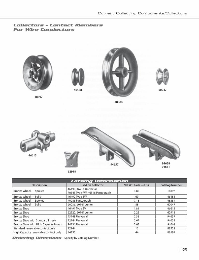
III-25
Current Collecting Components/Collectors
Collectors - Contact Members For Wire Conductors
Catalog InformationDescription Used on Collector Net Wt. Each — Lbs. Catalog Number
Bronze Wheel — Spoked 46199, 46211 Universal70545 Type PW, 46516 Pantograph 1.88 18897
Bronze Wheel — Solid 46492 Type BW .69 46488Bronze Wheel — Spoked 70086 Pantograph 7.13 48384Bronze Wheel — Solid 60036, 60141 Junior .88 60047Bronze Shoe 46491 Type BV 1.81 46615Bronze Shoe 62920, 60141 Junior 2.25 62918Bronze Shoe 93148 Universal 2.38 94657Bronze Shoe with Standard Inserts 92944 Universal 2.69 94658Bronze Shoe with High Capacity Inserts 94136 Universal 3.63 94661Standard renewable contact only 92944 .13 88321High Capacity renewable contact only 94136 .44 88597
Ordering Directions - Specify by Catalog Number.
18897
60047
48384
46488
46615
62918
94657 9465894661

III-26
Current Collecting Components/Collectors
Collectors - Contact Members For Wire Conductors
18897 46488 48384
60047 46615 62918
94657 9465894661

IntroductionThe C-Bar Conductor System is a medium capacity system for use where load current requirements do not warrant the use of our high capacity integrated systems. The compactness, rugged design, and economy make this an ideal Conductor System for all types of A.C. and D.C. current collection applications. C-Bar may be mounted with the conductor surface in any plane. Under and side running are the most common mounting positions. The C-Bar Conductor is available in 350 Amp. Bronze Conductor, 450 Amp. Aluminum Conductor and 550 Amp. Copper Conductor. Standard Collectors are available from 25 to 275 ampere capacities.
This entire system is supplied as a package complete with insulators, hangers, conductors and collectors, ready to mount on building or structural supports.
Lightweight design and erection simplicity reduces installation costs in compari-son to other types of systems. No field welding, drilling or cutting is required. Assembly is accomplished by means of standard hex wrenches. Conductors are furnished in factory pre-cut lengths to fit your requirements. Installation and application drawings, engineered for the job, accompany each system and locate the various components for erection.
Our sales personnel and engineering staff are available for aiding in the selection of the most economical system for your present and future requirements.
C-B
ar

IV-2
Aluminum, Bronze or Copper C-Bar for Medium Capacity Cranes
Typical InstallationsThe C-Bar Conductor System, due to its medium capacity can serve a wide range of applications. It is ideal for applications inside or outside, on main runway and cross travel for traveling cranes, material handling units, machine tools, rotary kiln tempera-ture recording, etc.
Special ApplicationsThe C-Bar system has been widely used to fit special applications. The Senate Subway C-Bar system has been in operation for a number of years. Its applica-tion is unusual since the C-Bar system powers subway cars around curves. A later installation was the House of Representatives subway that also required curved track sections.
An interesting and unusual application is the St. Louis Arch. Passengers are loaded In cars below the base and transported to the top of the Arch. These cars receive their power from a C-Bar system that is curved for almost the entire length of the system.
St. Louis Arch
Senate Subway

IV-3
Aluminum, Bronze or Copper C-Bar for Medium Capacity Cranes
ConductorThe C-Bar Conductor section is available in three materials; Bronze, Aluminum, and Copper, with nominal 350, 450, and 550 ampere capacity, respectively. Ampere ratings are based on a 30˚C rise over a 40˚C ambient in still but unconfined air. The box-like construction provides high mechanical rigidity and allows a large surface area for heat dissipation and current collection. Conductors are of non-magnetic materials to reduce voltage drop.
Conductors are normally furnished in 30 foot lengths. “L” as specified in catalog number is length-hence, the catalog number for a 30 foot copper conductor section would be 99341-30. Shorter lengths are available for use where system clearances will not allow insertion of the standard 30 foot length. Fractions of a foot should be avoided; i.e.: if a 16'6" section is required, order a 17 foot section and cut to required size.
Insulated Hanger The Insulated Hanger is used to support the conductor section and to electrically insulate it from the supporting structure.
The Insulated Hanger is positioned within the C-Bar Conductor; as shown in the C-Bar cut away. The conductor can slide freely over the hanger to allow movement from expansion and contrac-tion due to temperature changes.
It is normally recommended that insulated hangers be used every five (5) feet along the conductor run.
The insulators are polyester fiberglass, with a 5/8" mounting tap, and are recommended for indoor or outdoor installations.
Bronze Aluminum Copper
Conductor CharacteristicsConductor Bronze Aluminum Copper
Catalog Number 99823-L 99418-L 99341-L
Cross-Sectional Area 355 MCM 457 MCM 355 MCM
D.C. Resistanc /1,000 ft. @ 20˚C-OHMS. .10426 .04125 .02945
Conductivity % lACS 20 C 28 56 99
A.C. Resistance / 1,000 ft. @ 20˚C-OHMS. .10582 .0421 .0300
Self GMD (Ds) inches .51 .491 .48
CurrentRatings*Continu-
ous
30˚C over 40˚C40˚C over 40˚C70˚C over 40˚C
350450550
450550650
550650750
Weight per foot - lbs. 1.07 .428 1.07*Ratings are based on the average indicated temperature rise of
new conductors in still but unconfined air.
Insulator Material Polyester Fiberglass
Catalog Number 105430
Standard Color Red
Creepage Distance - Inches 21/2
Dielectric Strength
Dew Flashover 15
KV Dry, S. T. 38
Tensile Strength - Lbs. 3,500
Cantilever Strength - Lbs.* 1,000
*Measured at center line of hanger insert.

IV-4
Aluminum, Bronze or Copper C-Bar for Medium Capacity Cranes
Splice Joint AssemblyThe Splice Joint joins the C-Bar Conductor as shown in the cutaway view.
The splice joint assembly is used to join and align adjacent conductor sections. It is easily installed with no drilling required.
The splice joint maintains positive alignment and provides electrical continuity. The two adjacent conductors are solidly clamped between a tongue-like bar and a clamping plate. Four high strength bolts insure a firm mechanical and electrical connec-tion.
Anchor AssemblyThe Anchor Assembly shown in the cutaway view illustrates the mechanical barriers within the C-Bar Conductors which are used in conjunction with an insulated hanger to secure the conductor at some pre-determined point in the system.
Anchors are used in conjunction with Insulated Hangers to restrict the longitudinal movement of the conductors. They prevent creeping of the conductor and unnecessary stressing of the Insulated Hangers throughout the system.
On systems under 200 feet long, anchors are placed at the center of the system.
On systems over 200 feet long, anchors used in conjunc-tion with expansion joints are employed to control the direction of expansion and contraction of conductor sections.
Note: The insulated hanger is not included with the anchor assembly and must be ordered separately.
System Splice Joint Catalog No. Splice Joint Rating*
Aluminum 96945 450
Copper/Bronze 98361 550
*Based on a 30˚C rise over 40˚C ambient, still air.
System Anchor Catalog Number
Bronze 98752
Aluminum 98746
Copper 98752
CONDUCTOR

IV-5
Aluminum, Bronze or Copper C-Bar for Medium Capacity Cranes
Feeder AssemblyThe Feeder Assembly is shown in the cutaway view installed in the C-Bar Conductor.
The Feeder Assembly provides electrical connec-tions to the C-Bar Conductor System.
It may be located at any point in the system, but should be kept at least six (6) inches away from nearest component (hangers, etc.), as contact with these components will prevent free sliding of the conductor during expansion and contrac-tion.
Feeder Assembly includes feeder lug, hardware, and clamping bar.
Expansion Joint AssemblyThe Expansion Joint Assembly illustrated in the cutaway view shows how it joins conductors and maintains electrical continuity by means of a flexible copper braided conductor.
The expansion joint, in conjunction with anchors, is used to accommodate the difference in expansion between the conductor and the structure on which the system will be supported.
The expansion joint will accommodate a maxi-mum movement of 3/4". The flexible copper braid carries the current across the gap between conductors.
Feeder Wire SizeFeeder Assembly Catalog No.
Aluminum, Bronze & Copper Systems
#16 to #14#12 to #10
#8 Solid to #6 Str.#4 Solid to #1 Str.
#2 to 2/0 Str.1/0 to 4/0 Str.
3/0 to 300 MCM300 to 500 MCM500 to 800 MCM
Contact Trans Tech
System Expansion Joint Cat. No. Rating*
Dim. “A” Maximum
Indoor Outdoor
Bronze 96059 350 200' 140'
Aluminum 96035 450 150' 100'
Copper 96079 550 200' 140'
*Based on a 30˚C. rise over 40˚C. ambient, still air.
TYPICAL APPLICATIONNOTE: Conductor gap setting is based on
both the ambient temperature at the time of installation and the expected temperature
variation to which the system will be exposed.

IV-6
Aluminum, Bronze or Copper C-Bar for Medium Capacity Cranes
Isolating JointThe Isolating Joint is used to insulate adjacent conductor sections from each other without interfer-ing with collector travel. It allows portions of the system to be electrically disconnected while opera-tions continue on other live sections. The air gap between C-Bar Conductors should be 11/4" maxi-mum.
At installations where more than one crane will be operated on a single conductor system, the isolating joint is used to create maintenance and repair bays.
The isolating joint may be inserted at any point along the system in place of a standard splice joint assem-bly. When properly installed, it assures correct alignment between adjacent conductors.
There are two methods of feeding the conductor system at isolation joints. Each side can be fed individually through adequate safety switches, or the isolation joint can be by-passed with the use of feeder assemblies and a suitable switch.
Covered C-Bar Conductor SystemInsulated C-Bar Conductor Systems are available. They provide protection with an extremely tough electrical grade thermoplastic jacket suitable for indoor or outdoor installation.
Conductor sections up to 30 feet in length are furnished assembled with jacket, hangers, or other components required for the particular application. The jacket is red in color for safety purposes and can be removed without disturbing the system.
System Insulating Joint Catalog No.*
Aluminum 9955201
Copper/Bronze 9955202
*Isolating Joint Assembly does not include feeder assemblies or switches, but is complete with hardware .

IV-7
Aluminum, Bronze or Copper C-Bar for Medium Capacity Cranes
Run-Off ConductorRun-off Conductors are used to provide a break in the conductor system where runways are interrupted by railroad crossings, roads, etc.
Single-Arm CollectorsSingle-arm collectors are available for various current ratings, depending on such factors as shoe material, conditions of service, type of installation, etc.
All single-arm collectors listed are identical except for the contact blocks and mounting arrangement. The contact blocks are inter-changeable between all collectors. They are quickly removed by loosening two bolts on the assembly. Replaceable contact blocks are listed separately. Contact shoe pressure is controlled by adjusting the spring location in the slots of the collector base. Power connection (by customer) is to be made at shunt connection on mounting base. Mounting insulators or insulated mounting boards are not included with the collector assembly and must be ordered separately.
RUN-OFF ConductorBronze Aluminum Copper
Catalog Number Contact Trans Tech
Two collectors are required to insure continuous operation across the runway interruption. Only cross-arm collectors can be used on systems
with run-off conductors.
Power must be supplied to both sides of the runway interruption in a manner similar to that illustrated in the isolating joint wiring diagrams.
“L” as specified in catalog number is length in feet; hence, a 20 foot aluminum run-off conductor would be 14·00181-20. Fractions of a foot
should be avoided.
Colle
ctor
Cat
. No.
Cond
ucto
r Sy
stem
Current Rating**40˚C. Ambient Inches
Cont
act B
lock
M
ater
ial
Cont
act B
lock
Ca
t. N
o.
30˚C
. Ris
e
40˚C
. Ris
e
50˚C
. Ris
e A min.
B
99389-01Bronze
AluminumCopper
252530
303035
505060
3 2Electro-
graphitic Carbon*
13/4 wide 99412
99389-02Bronze
AluminumCopper
75100125
100125150
150200250
3 2 Metal graphite
13/4 wide 99413
99389-05Bronze
AluminumCopper
252530
303035
505060
31/2 21/2
Electro-graphitic Carbon*
21/2 wide
99389-06Bronze
AluminumCopper
75100125
100125150
150200250
31/2 21/2Metal
graphite21/2 wide
99715
*Indoor System Only.**The ratings given are based on the average indicated temperature rise over a 40˚C. Ambient in still, but unconfined air. Conductors spaced at 3".

IV-8
Aluminum, Bronze or Copper C-Bar for Medium Capacity Cranes
Cross-Arm CollectorsCross-arm collectors are available for various current ratings, depending on such factors as shoe material, conditions of service, type of installation, etc.
All cross-arm collectors listed are identical except for the contact shoe blocks and mounting arrangement. The contact blocks are interchangeable between all single and cross-arm collectors. They are quickly removed by loosening two bolts on the assembly. Replacement contact blocks are listed separately.
Contact shoe pressure is controlled by spring force adjustment. This is accomplished by relocating the spring in the holes provided in the contact block holder. Adjustable stops are provided to control maximum operating height for run-off applications on interrupted crane runways.
Mounting insulators or insulated mounting boards are not included with the collector assembly and must be ordered separately.
Colle
ctor
Cat
. No.
Cond
ucto
r Sy
stem
Current Rating**40˚C. Ambient Inches
Cont
act B
lock
M
ater
ial
Cont
act B
lock
Ca
t. N
o.
30˚C
. Ris
e
40˚C
. Ris
e
50˚C
. Ris
e A min.
B
99634-01Bronze
AluminumCopper
505060
606075
100100120
3 2Electro-
graphitic Carbon*
13/4 wide
99412
99634-02Bronze
AluminumCopper
175225275
200250300
350450550
3 2 Metal graphite
13/4 wide
99413
99634-05Bronze
AluminumCopper
505060
606075
100100120
31/2 21/2
Electro-graphitic Carbon*
21/2 wide
99634-06Bronze
AluminumCopper
175225275
200250300
350450550
31/2 21/2Metal
graphite
21/2 wide
99715
*Indoor System Only.**The ratings given are based on the average indicated temperature
rise over a 40˚C. Ambient in still, but unconfined air. Conductors spaced at 3".

IV-9
Aluminum, Bronze or Copper C-Bar for Medium Capacity Cranes
Tracking Shoe CollectorThe tracking shoe collectors are recommended for curved rail systems or systems where extreme horizontal misalignment is present. The collec-tors are not recommended for side running operation.
The contact force is adjustable to meet special operating conditions.
Mounting insulators or insulated mounting boards are not included with the collector assembly and must be ordered separately.
Colle
ctor
Cat
. No.
Cond
ucto
r Sy
stem
Current Rating**40˚C. Ambient Inches
A min.
Cont
act B
lock
M
ater
ial
Cont
act B
lock
Ca
t. N
o.
30˚C. Rise
40˚C. Rise
50˚C. Rise
105396Bronze
AluminumCopper
75100125
100125150
150200250
3Metal
Graph-ite
1" wide 105385
**The ratings given are based on the average indicated temperature rise over a 40˚C.
Ambient in still, but unconfined air. Conductors spaced at 3".
Collector Mounting InsulatorsInsulator Catalog Number
A B
Red-Poly#15-51-35
Red-Poly#15-61-17
Material Polyester Fiberglass
Creepage Distance -Inches- 21/2" 3
Dielectric Strength KV
Dew-KY Flashover 15 17
Dry-KV Short-Time 38 40
Tensile Strength — Lbs. 3,500 5,000
Cantilever Strength Inch-Pounds 3,000 4,500

IV-10
Aluminum, Bronze or Copper C-Bar for Medium Capacity Cranes
TECHNICAL DATA
CONDUCTOR SIZE CALCULATION
There are two accepted methods of determining the maximum ampere demand of one or more cranes on a single runway.
Method AMaximum load equals the sum of all main and auxiliary hoist H.P. plus one-half (1/2) the sum of all bridge motor and trolley H.P.
Method BMaximum load equals one-half (1/2) the sum of all motor and accessory H.P.
CALCULATION
Load H.P. (Method A or B) x amperes per H.P. (Table A) = maximum ampere demand.
Maximum ampere demand x crane factor (Table C) = adjusted maximum ampere demand.
VOLTAGE DROP CALCULATIONSymbolsVL = Line Voltage at Feeder (Source).
VD = Voltage Drop.
I = Load Amperes.
L = Effective System Length in Feet. Maximum distance from feeder to end of system.
Roc = D. C. Resistance-ohms/1000 feet.
K = Voltage Drop Multiplier (Table B). A factor derived from tests which accounts for variables such as A. C. resistance, inductive reactance, power factor, phase spacing, and conductor shape factors.
Formulas
Direct Current
VD = ILRoc 500
Alternating Current - Three Phase (80 percent Power Factor-Flat Spacing) VD=I L K (Line to Line*)
*For Line to Neutral Voltage Drop divide by 1.73.
Voltage Regulation % Regulation = VD x 100 VL-VD
Example
Length of runway, 200 feet, operating on 440 volts, 3 phase, 60 cycle, phase spacing 3 inches, feeder location-center of runway, one crane on runway. By Method "A," the maximum ampere demand would be calculated as follows:
ACTUAL CALCULATED
H.P. H.P.
Main Hoist 90 90Auxiliary Hoist 100 100Bridge 150 75Trolley 30 15 Total 280 H.P.
From Table A multiplier is 1.5. 1.5 x 280 H.P. = 420 maxi-mum ampere demand. Based on a 30˚C rise over 40˚C ambient, you could select the 450 aluminum C-Bar series for this application.
From Table B, the 450 Series with a 3 inch phase spacing has a K multiplier of 115.6 x 10˚ - therefore:
VD (Voltage Drop) = 1 x L x K
VD = 420 x 100 x (115.6) (10-6)
= 4.86 volts
% Regulation = VD x 100 VL-VD
Regulation = 4.86 x 100 = 1.12% 440-4.86
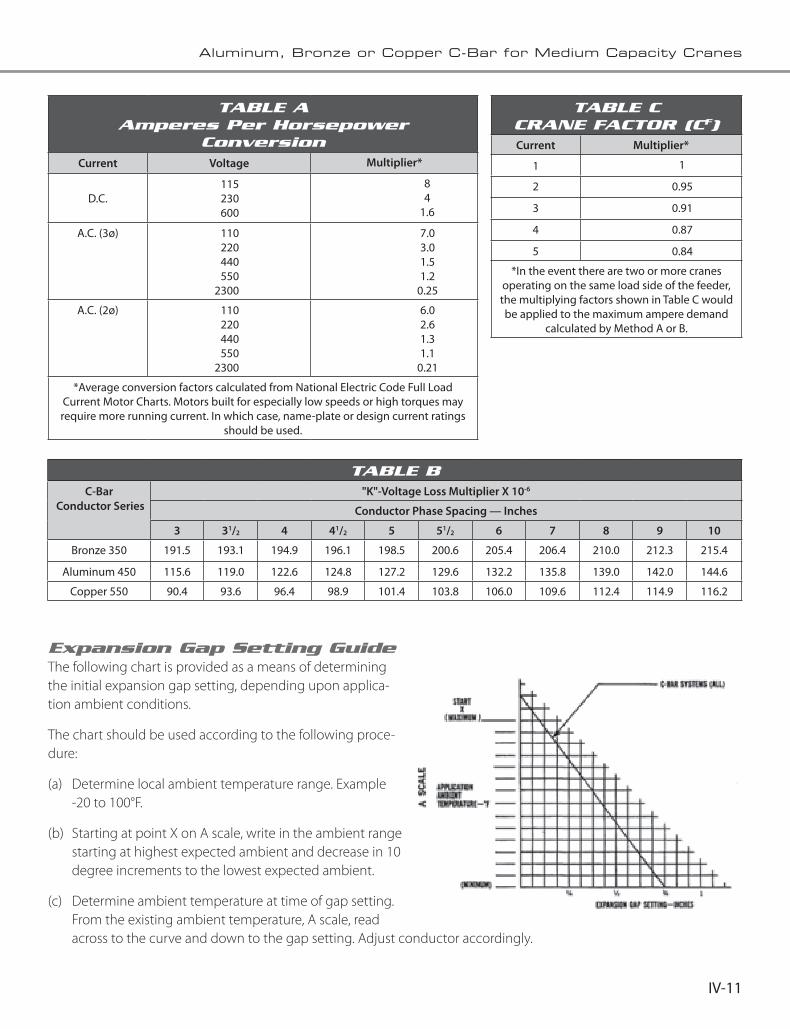
IV-11
Aluminum, Bronze or Copper C-Bar for Medium Capacity Cranes
Expansion Gap Setting GuideThe following chart is provided as a means of determining the initial expansion gap setting, depending upon applica-tion ambient conditions.
The chart should be used according to the following proce-dure:
(a) Determine local ambient temperature range. Example -20 to 100°F.
(b) Starting at point X on A scale, write in the ambient range starting at highest expected ambient and decrease in 10 degree increments to the lowest expected ambient.
(c) Determine ambient temperature at time of gap setting. From the existing ambient temperature, A scale, read across to the curve and down to the gap setting. Adjust conductor accordingly.
TABLE A Amperes Per Horsepower
ConversionCurrent Voltage Multiplier*
D.C.115230600
84
1.6
A.C. (3ø) 110220440550
2300
7.03.01.51.2
0.25
A.C. (2ø) 110220440550
2300
6.02.61.31.1
0.21
*Average conversion factors calculated from National Electric Code FulI Load Current Motor Charts. Motors built for especially low speeds or high torques may require more running current. In which case, name-plate or design current ratings
should be used.
TABLE C CRANE FACTOR (CF)Current Multiplier*
1 1
2 0.95
3 0.91
4 0.87
5 0.84
*In the event there are two or more cranes operating on the same load side of the feeder, the multiplying factors shown in Table C would be applied to the maximum ampere demand
calculated by Method A or B.
TABLE BC-Bar
Conductor Series"K"-Voltage Loss Multiplier X 10-6
Conductor Phase Spacing — Inches
3 31/2 4 41/2 5 51/2 6 7 8 9 10
Bronze 350 191.5 193.1 194.9 196.1 198.5 200.6 205.4 206.4 210.0 212.3 215.4
Aluminum 450 115.6 119.0 122.6 124.8 127.2 129.6 132.2 135.8 139.0 142.0 144.6
Copper 550 90.4 93.6 96.4 98.9 101.4 103.8 106.0 109.6 112.4 114.9 116.2

IV-12
Aluminum, Bronze or Copper C-Bar for Medium Capacity Cranes
TYPICAL SPECIFICATIONS
System - GeneralEach system shall consist of necessary conductor sections, hanger supports, insulators, anchor supports, expansion joints, joint plates and collectors, as determined from plans and specifications. All component parts shall be of standardized design and fully interchangeable. Engagement of the conduc-tor with all other components of the system shall be effected without drilling, welding, or alteration of the conductor and associated components.
The conductor system shall be of the C-Bar type as manufac-tured by Trans Tech.
ConductorsThe current carrying conductors shall be made of (bronze) (aluminum) (copper) and shall have a continuous current carrying capacity of (350)(450) (550) amperes per rail based on a 30°C rise over a 40°C ambient. The conductors shall have sufficient thermal capacity to sustain a 300% overload for intermittent duty loads. The conductor section shall be a one-piece (bronze) (aluminum) (copper) conductor of uniform extruded cross-section so as to present a smooth, flat surface for current collection. The conductor shall have a minimum cross-sectional area of 355 MCM (bronze), 457 MCM (aluminum), 355 MCM (copper), and shall be of box-like configuration for mechanical rigidity.
The complete rail system shall consist of standard conductor lengths aligned in end-to-end relationship. Aligning and joining means between conductor section shall be accom-plished by a special extruded bar which shall engage the conductor sections and provide an interlocking key to eliminate misaligned meeting ends of adjoining rail sections. The conductor shall have a current collection surface one (1) inch wide.
Insulating HangersThe conductor hanger shall support the conductor section, and shall insulate it from the structure to which it is mounted. The insulator shall be molded of fiberglass reinforced polyester material. The insulated hanger shall provide free
sliding of the conductor section due to expansion and contraction throughout the system. All insulating hanger hardware shall be 5/8 - 11 thread size. The hanger design shall be such that it would be possible to turn the conductor 360 degrees about the vertical axis.
Splice Joints and Expansion JointsSplice and expansion joints shall be provided to join adjacent conductor sections as required. The joints shall consist of special extruded bars which slip inside the conductor to provide an interlocking key to eliminate misalignment. In the standard joint assembly, the adjacent conductor sections shall be rigidly connected. In the expansion joint assemblies, the joint shall include a conductive flexible braid. All components shall be of sufficient size and electrical capacity to be compat-ible with the conductor rating. All joint assemblies shall have an electrical efficiency of greater than one hundred (100) percent.
CollectorsCollectors shall be rated on the basis of a 30°C rise over a 40°C ambient. The collectors shall have sufficient overload capacity to carry 300% of the rated current for starting and surge loads.
All collector assemblies shall be constructed of high quality material and shall be of sufficient size to withstand the abuse of the intended service conditions.
The contact shoes shall consist of a mounting support and interchangeable contact inserts. Contact shoe pressure shall be adjustable. All collector springs shall be cadmium plated. The contact shoes shall be capable of transversing all breaks and expansion gaps smoothly with a minimum of arcing.
Special ComponentsIsolating joint assemblies can be provided to allow shutdown of portions of the system while operations continue on other sections. The isolating joint assembly shall provide a 11/4 inch air gap between conductors, shall maintain positive align-ment between them, and shall not hinder the passage of the collector contact shoes across the air gap.
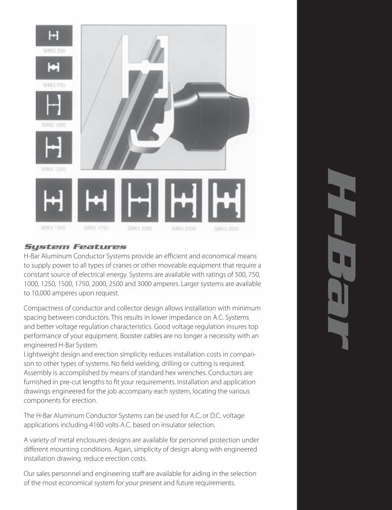
System FeaturesH-Bar Aluminum Conductor Systems provide an efficient and economical means to supply power to all types of cranes or other moveable equipment that require a constant source of electrical energy. Systems are available with ratings of 500, 750, 1000, 1250, 1500, 1750, 2000, 2500 and 3000 amperes. Larger systems are available to 10,000 amperes upon request.
Compactness of conductor and collector design allows installation with minimum spacing between conductors. This results in lower impedance on A.C. Systems and better voltage regulation characteristics. Good voltage regulation insures top performance of your equipment. Booster cables are no longer a necessity with an engineered H-Bar System.Lightweight design and erection simplicity reduces installation costs in compari-son to other types of systems. No field welding, drilling or cutting is required. Assembly is accomplished by means of standard hex wrenches. Conductors are furnished in pre-cut lengths to fit your requirements. Installation and application drawings engineered for the job accompany each system, locating the various components for erection.
The H-Bar Aluminum Conductor Systems can be used for A.C. or D.C. voltage applications including 4160 volts A.C. based on insulator selection.
A variety of metal enclosures designs are available for personnel protection under different mounting conditions. Again, simplicity of design along with engineered installation drawing. reduce erection costs.
Our sales personnel and engineering staff are available for aiding in the selection of the most economical system for your present and future requirements.
H-B
ar

V-2
Aluminum H-Bar
ConductorThe Aluminum H-Bar Conductor is designed for main runway or cross travel applications. It may be mount-ed with the conductor surface in any plane. Under or side running are the most common mounting positions. The “H” configuration was selected for its structural strength allowing maximum hanger spacing, thereby reducing installation costs. The conductor is extruded from high conductivity aluminum alloy in maximum 30 foot lengths. Shorter lengths are available (5 foot minimum) in one foot increments to coincide with your runway length requirements.
STANDARD COMPONENTS — System - SeriesComponent 500 750 1000 1250 1500 1750 2000 2500 3000
Conductor 106100 106101 106102 106103 106104 106105 106106 106107 106108
Hanger Assembly 106125 106125 106126 106126 106126 106126 106127 106127 106127
Splice Joint Assembly 106130 106130 106131 106131 106132 106132 106133 106134 106135
Anchor Assembly 106140 106140 106141 106141 106141 106141 106142 106142 106142
Isolating Joint Assembly 106145 106145 106146 106146 106146 106146 106147 106147 106147
Fixed Expansion Joint Assembly 106150 106150 106151 106151 106152 106152 106153 106153 106154
Floating Assembly Joint (Bldg.) 106160 106161 106162 106163 106164 106165 106166 106167 106168
Feeder Assembly (Less Lugs)106170106171
106170106171
106172106173
106172106173
106172106173
106172106173
106174106175
106174106175
106174106175
Metalized Contact Conductor 106190 106191 106192 106193 106194 106195 106196 106197 106198
Syst
em A
mpe
re
Ratin
g
Cond
ucto
rCa
t. N
o.
A B C
Cross Sectional
Area
Wei
ght
Lbs/
Ft.
DC
Resi
stan
ce
Ohm
s/ 1
000
ft. a
t 20
˚C.
AC
Resi
stan
ce
Ohm
s/ 1
000
ft. a
t 20
˚ C.
Self
Geo
met
ric
Dis
tanc
e d
s - I
nche
s
Current Rating Amperes-Continuous
40˚ C. Ambient
Sq. Inches CMx 106 30˚ C.
Rise40˚ C. Rise
70˚ C. Rise
500 106100 11/16 1 5/32 0.51 0.65 0.60 0.0292 0.0349 0.55 500 575 750
750 106101 11/16 11/41/4 0.76 0.97 0.89 0.0196 0.0213 0.66 750 850 1100
1000 106102 21/4 11/23/16 1.14 1.45 1.34 0.0130 0.0150 0.81 1000 1150 1500
1250 106103 21/4 13/41/4 1.51 1.92 1.78 0.0098 0.0119 0.93 1250 1450 1850
1500 106104 21/4 2 9/32 1.90 2.41 2.22 0.00784 0.0101 1.04 1500 1700 2200
1750 106105 21/4 21/411/32 2.26 2.88 2.66 0.00655 0.00845 1.14 1750 2000 2600
2000 106106 33/4 21/25/16 2.90 3.68 3.40 0.00513 0.00748 1.28 2000 2300 3000
2500 106107 33/4 23/43/8 4.01 5.11 4.72 0.00369 0.00611 1.49 2500 2850 3750
3000 106108 33/4 3 17/32 5.40 6.87 6.35 0.00274 0.00520 1.67 3000 3400 4500

V-3
Aluminum H-Bar
Hanger AssemblyThe hanger assembly is used to support the conductor section with the aid of an insulator.The hanger is made of cast aluminum, nylon coated to assure free sliding during expansion and contraction of the conductor through the hanger. Conductor “lock-up” has been eliminated by this added feature. The hanger, like the conductor, may be mounted in any plane.
Insulator selection depends on the operating voltage of the system and the hanger bolt size.
Syst
em
Han
ger
Cat.
No.
A B C
Insu
lato
r Bo
lt
Max
imum
Su
ppor
t Ce
nter
s Fe
et
Net
Wei
ght
Lbs.
500-750 106125 11/25/8 11/2
3/8-16 UNC 6 .17
1000-1250106126 2 11/16 27/8
5/8-11 UNC12
.311500-1750 14
2000
106127 3 13/8 45/85/8-11 UNC
16
1.22500 18
3000 20
Splice Joint AssemblyThe splice joint assembly connects and aligns adjoining conductor sections without drilling or welding. Simplicity of the assembly requires only standard hex wrenches. Bolts secure a Belleville-spring-type, aluminum plate which insures the electrical connection.
The aluminum splice joint has an electrical efficiency of greater than 100% when compared by the resistance test method (NEMA SG1-5.02) to an equal length of conductor.
Syst
em
Splic
e Jo
int
Cat.
No.
A B C D
Num
ber o
f Bol
ts
Ratin
g A
mpe
res
30˚C
. Ove
r 40˚
C.
Net
Wei
ght L
bs.
500-750 106130 6 5/8 11/27/16 4 750 .59
1000-1250 106131 8 11/16 27/85/8 4 1250 2.25
1500-1750 106132 10 11/16 27/85/8 4 1750 2.81
2000 106133 11 13/8 41/2 1 6 2000 7.94
2500 106134 14 13/8 41/2 1 6 2500 9.94
3000 106135 18 13/8 41/2 1 8 3000 12.86

V-4
Aluminum H-Bar
Anchor AssemblyAnchor assemblies are employed at one or more points in the system to secure the conductor to a fixed point from which the conductor can expand or contract through the hangers.
The assembly consists of an aluminum extrusion with bolts that securely clamp to the conductor.
An anchor assembly replaces a hanger in the system and requires two mounting insulators.
Insulator selection depends on the operating voltage of the system and the anchor bolt size.
Isolating Joint AssemblyThe Isolating Joint Assembly is used to insulate adjacent conductor sections from each other with-out interfering with collector travel. It allows portions of the system to be electrically disconnected while operations continue on other live sections. At installations where more than one crane will be operated on a single conductor system, the isolating joint is used to create maintenance and repair bays. The isolating joint may be inserted at any point on the system in place of a standard splice joint assem-bly. When installed, it assures correct alignment between adjacent conductors. There are two meth-ods of feeding the conductor system at isolation joints. (See Diagram).
Each side can be fed individually through adequate safely switches or the isolation joint can be by-passed with the use of feeder assemblies and a suitable disconnect switch.
System Anchor Cat. No. A B C D E
Insu
lato
r Bo
lt
Net Weight
Lbs.
500-750 106140 121/25/8 11/2 3 1/8
7/16 3/8 -16 UNC 1.15
1000-1750 106141 21 11/16 27/8 7 3/85/8
5/8 -11 UNC 5.27
2000-3000 106142 25 1 3/8 41/2 9 3/8 1 5/8 -11 UNC 15.12
Syst
em
Isolating Joint
Cat. No.
Type A B C D E
Net Weight
Lbs.
500-750 106145 I 18 5/8 11/2 7 11/2 1.60
1000-1750 106146 I 21 11/16 27/8 81/2 2 4.68
2000-3000 106147 II 25 13/8 5 101/2 21/4 14.25

V-5
Aluminum H-Bar
Fixed Expansion JointFixed expansion joints are sometimes necessary to accommodate building or supports structure expansion. Normal indoor installations do not require expansion joints if temperature ranges do not exceed 80˚F. Extreme variations in temperature will require expansion joints on longer systems. Electrical continuity is maintained through flexible copper shunts. Shunts are separated from the aluminum by use of bi-metal plates. Conductor gap setting is based on both the ambient temperature at the time of installation and the expected temperature variation to which the system wiIl be exposed. Two insulators are required with each fixed expansion joint.
Floating Expansion JointFloating Expansion Joints are used only when the gap setting exceeds the fixed expansion joint capability. Electrical continuity is maintained through flexible copper shunts. Shunts are separated from the aluminum by use of bi-metal plates.
Conductor gap setting is based on both the ambient temperature at the time of installation and the expected temperature variation to which the system will be exposed. NO insulators are required.
System
Expa
nsio
n Jo
int C
at.
No
Max
imum
Expa
nsio
n (X
) inc
hes
A B C D E Insulator Bolt
Rating Amperes
30˚C Over 40˚C
Recommended Max. System LengthNet Wt
Lbs.Ft. Center Anchor Segment Between
Expansion Joints
Indoor Outdoor Indoor Outdoor
500-750 106150 11/2 405/85/8 11/2 113/8
3/43/8-16 UNC 750
Not
requ
ired
fo
r nor
mal
in
stal
latio
n
500 --- 100 3.891000-1250 106151 21/2 57 11/16 27/8 141/2 11/8
5/8-11 UNC 1250 1000 --- 250 18.561500-1750 106152 21/2 57 11/16 27/8 141/2 11/8
5/8-11 UNC 1750 1500 --- 250 19.962000-2500 106153 21/2 63 13/8 41/2 181/2 11/8
5/8-11 UNC 2500 2000 --- 400 45.913000 106154 21/2 63 1 3/8 41/2 181/2 13/8
5/8-11 UNC 3000 2500 --- 400 48.71
System
Expa
nsio
n Jo
int C
at.
No
Max
imum
Expa
nsio
n (2
X) in
ches
A B C D
Rating Amperes
30˚C Over 40˚C
Net Wt
Lbs.
500 106160 3 38 15/8 21/43/4 500 7.30
750 106161 3 38 17/8 21/43/4 750 7.59
1000 106162 5 56 29/16 313/16 11/8 1000 33.341250 106163 5 56 213/16 313/16 11/8 1250 33.781500 106164 5 56 31/16 313/16 13/8 1500 37.021750 106165 5 56 35/16 313/16 13/8 1750 37.462000 106166 5 56 37/8 51/2 11/8 2000 66.082500 106167 5 56 41/8 51/2 11/8 2500 67.403000 106168 5 56 43/8 51/2 13/8 3000 74.61

V-6
Aluminum H-Bar
System Feeder Cat. No Type A B C D
Feeder Lug Provision Rating Amperes 30˚C Over 40˚C
Net Wt Lbs.Quantity Bolt Size Bolt Spacing "E"
500-750106170 I 81/4 5/8 11/2
7/161
1/2-13 UNC 13/4
500 .82106171 II 101/2 2 750 1.26
1000-1750106172 II 14 11/16 27/8
5/8 2 1000 3.57106173 III 23 11/16 27/8
5/8 3 1/2-13 UNC 13/4 1750 5.70
2000-3000106174 III 233/4 13/8 41/2 1 3
1/2-13 UNC 13/4 300014.90
106175 IV 35 1 3/8 41/2 1 4 21.50
Feeder AssemblyThe Feeder Assembly provides the electrical connec-tion from the power source to the conductor system. It may be located at any point within the system.
Long systems should locate the feeder near the center of the system. Feeders should be located no closer than 6 inches from the nearest component. Provisions are made for 1, 2, 3 or 4 feeder lugs. Lugs are not furnished with the assembly except by request. Feeders are tapped for standard NEMA type lugs. Bi-metal plates are provided to prevent electro-lytic action between aluminum and the bronze or copper lug.

V-7
Aluminum H-Bar
Collector Assembly The collector assembly is used to pick up current from the conductor and transmit it to the crane. The contact shoe, which is in contact with the conductor, is made of a metal graphite composi-tion which insures long shoe life without affect-ing conductor wear. The collector arms are of cast aluminum, and the assembly has provisions for varying the contact shoe pressure by means of an adjustable spring. The arm assembly provides for vertical misalignment while the shoe width accommodates for horizontal misalign-ment. The entire collector assembly can be mounted in any plane. Under or side running are the most common mounting positions.
Collectors can be provided with one, two, or four arms depending on the current requirements. Two insulators must be used with the one and two arm collector while four are required for the four arm unit. Normally, the same insulator used for the hangers would be employed.
Collector arms, sub-assemblies, contact shoes, and other components are readily available and can be ordered separately, from the entire collector assembly.
System Collector Cat. No.
Rating Amperes 30˚C Over
40˚C
No. of Arms
A Min. B C
Net Weight
Lbs.
500-175099832 250 1
61/2 85/8 57/16
2899668 600 2 5799833 1200 4 116
2000-3000
106391 500 18 10 67/16
30106392 1000 2 60106394 2000 4 125
Current R
atin
g
Catalog Number
System Series500 - 1750 2000 - 3000
Single Arm (1)
Double Arm (2)
Four Arm (4)
Single Arm (1)
Double Arm (2)
Four Arm (4)
99832 99668 99833 106391 106392 106394
ContinuousDuty
Amperes40˚C Ambient
30˚C40˚C60˚C70˚C
250350
10001200
600750
22002500
1200150044005000
500650
12001500
1000130024003000
2000280050006000
IntermittentDuty
Amperes40˚C Rise
Over40˚C Ambient
1 Min - On1 Min - Off5 Min - On5 Min - Off
15 Min - On15 Min - Off
1050
950
600
2200
2000
1400
4400
4000
2800
1850
1700
1200
3600
3200
3000
7500
7000
6000

V-8
Aluminum H-Bar
No. 99832
No. 99668
No. 99833
No. 106391
No. 106392
No. 106394

V-9
Aluminum H-Bar
System LayoutThe first step in preparing a system layout is to select the proper amperage conductor rating required for the installation. Once the conductor size has been selected the hanger support-centers for that particular size con-ductor may be selected from the chart shown with the hanger assembly on Page 3. In order to determine if an expansion joint is required, refer to the fixed expansion joint chart. In the majority of installations none is required. This is due to the advanced design of the nylon coated hanger. In the event a building expansion joint occurs near mid-point in the system, a floating expansion joint assembly should be considered. Where no expansion joints are required, the system should be anchored approximately in the center. Anchor assemblies are shown on Page 4. The feeder assembly, if possible, should be
located near the center of the system. This reduces the effective systems length "L" which is used in the formula to determine the proper conductor amperage rating. Feeders with provisions for one to four lugs may be select-ed from the feeder assemblies on Page 6.
Careful attention must be given to mechanical clearances between components. All splice joints, expansion joints feeders, and isolation joints must be kept at a minimum of six (6) inches away from the nearest insulated hanger to insure free sliding of the conductor through the hanger.
The following symbols and example layouts are intended for a guide in preparing a layout. However, upon request Trans Tech will prepare an application layout to fit your requirements.
SYSTEM A —No Expansion Joint — Center Anchored
SYSTEM B —Floating Expansion Joint
SYSTEM C —Expansion Joint (Fixed)
SYSTEM D —Isolating Joint

V-10
Aluminum H-Bar
TECHNICAL DATA
CONDUCTOR SIZE CALCULATION
There are two accepted methods of determining the maximum ampere demand of one or more cranes on a single runway.
Method AMaximum load equals the sum of all main and auxiliary hoist H.P. plus one-half (1/2) the sum of all bridge motor and trolley H.P.
Method BMaximum load equals one-half (1/2) the sum of all motor and accessory H.P.
CALCULATION
Load H.P. (Method A or B) x amperes per H.P. (Table A) = maximum ampere demand.
Maximum ampere demand x crane factor (Table C) = adjusted maximum ampere demand.
VOLTAGE DROP CALCULATIONSymbolsVL = Line Voltage at Feeder (Source).
VD = Voltage Drop.
I = Load Amperes.
L = Effective System Length in Feet. Maximum distance from feeder to end of system.
RDC = D. C. Resistance-ohms/1000 feet.
K = Voltage Drop Multiplier (Table B). A factor derived from tests which accounts for variables such as A. C. resistance, inductive reactance, power factor, phase spacing, and conductor shape factors.
Formulas
Direct Current
VD = ILRDc 500
Alternating Current - Three Phase (80 percent Power Factor-Flat Spacing) VD=I L K (Line to Line*)
*For Line to Neutral Voltage Drop divide by 1.73.
Voltage Regulation % Regulation = VD x 100 VL-VD
Example
Length of runway, 400 feet, operating on 440 volts, 3 phase, 60 cycle, phase spacing 5 inches, feeder location-center of runway, one crane on runway. By Method "A," the maximum ampere demand would be calculated as follows:
ACTUAL CALCULATED
H.P. H.P.
Main Hoist 200 200Auxiliary Hoist 250 250Bridge (2 motors at 150 each) 300 150Trolley 60 30 Total 630 H.P.
From Table A multiplier is 1.5. 1.5 x 630 H.P. = 945 maxi-mum ampere demand. Based on a 30˚C rise over 40˚C ambient, you could select the 1000 aluminum H-Bar series for this application.
From Table B, the 1000 Series with a 5 inch phase spacing has a K multiplier of 67.22 x 10˚ - therefore:
VD (Voltage Drop) = I x L x K
VD = 945 x 200 x (67.22) (10-6)
VD = 12.7 volts
% Regulation = VD x 100 VL-VD
Regulation = 12.7 x 100 = 2.9% 440-12.7

V-11
Aluminum H-Bar
Expansion Gap Setting GuideThe following chart is provided as a means of determining the initial expansion gap setting, depending upon application ambient conditions.
The chart should be used according to the following procedure:
(a) Select system under consideration and respective curve line, indicat-ing maximum gap opening.
(b) Determine local ambient temperature rang: Example -20 to 100˚F.
(c) Starting at point X on A scale, write in the ambient range starting at highest expected ambient and decrease in 10 degree increments to the lowest expected ambient.
(d) Determine ambient temperature at time of gap setting. From the existing ambient temperature, A scale, read across to the appropriate curve and down to the gap setting. Adjust conductor accordingly.
TABLE A Amperes Per Horsepower Conversion
Current Voltage Multiplier*
D.C.115230600
84
1.6
A.C. (3ø) 110220440550
2300
7.03.01.51.2
0.25
A.C. (2ø) 110220440550
2300
6.02.61.31.1
0.21
*Average conversion factors calculated from National Electric Code FulI Load Current Motor Charts. Motors built for especially low speeds or high torques may require more running current. In which case, name-plate or design current ratings should be used.
TABLE C CRANE FACTOR (CF)
Current Multiplier*
1 1
2 0.95
3 0.91
4 0.87
5 0.84
*In the event there are two or more cranes operating on the same load side of the feed-er, the multiplying factors shown in Table C would be applied to the maximum ampere
demand calculated by Method A or B.
TABLE B
H-Bar Conductor
Series
"K"-Voltage Loss Multiplier X 10-6
Conductor Phase Spacing — Inches3 31/2 4 41/2 5 51/2 6 61/2 7 71/2 8 9 10
500 86.10 89.70 92.80 95.49 97.96 1000.2 102.3 104.1 106.0 107.5 109.0 111.8 114.2750 68.77 72.42 75.18 78.32 80.77 83.03 85.08 86.78 88.69 90.29 91.83 94.60 97.10
1000 58.62 64.74 67.22 69.46 71.48 73.42 74.97 76.77 78.25 81.02 83.481250 54.73 57.45 59.92 62.16 64.20 66.14 67.82 69.48 70.95 73.73 76.141500 49.54 52.29 54.76 57.00 59.05 60.94 62.66 64.26 65.80 68.56 71.731750 45.76 48.35 50.99 53.23 55.28 57.16 58.90 60.52 62.04 64.80 67.152000 48.72 50.76 52.09 54.40 55.99 57.52 60.29 63.322500 43.61 45.65 47.53 49.27 50.90 52.40 55.17 57.633000 40.06 42.16 44.04 45.77 47.41 48.73 51.68 54.15
V-12
Aluminum H-Bar
GENERAL SPECIFICATIONSThe conductor-collector system shall be of the H-Bar Alumi-num Series as manufactured by Trans Tech.
Each system shall consist of necessary conductor sections, hanger supports, insulators, anchor supports, expansion joints, collectors, and/or special components as determined from plans and specifications.
The conductor section shall be one-piece aluminum of H-Bar configuration with a flat contact surface. The conductor aluminum alloy shall have a minimum conductivity of 56% lACS and a current carrying capacity of (500) (750) (1000) (1250) (1500) (1750) (2000) (2500) (3000) amperes based on a 30˚C rise over 40°C ambient when operating in still, but unconfined air. The conductor shall have sufficient thermal capacity to withstand a 300% overload for intermittent duty cycles.
The conductor hangers shall be cast of high strength aluminum alloy. The hanger will be nylon coated to provide free conductor movement through the hanger to accom-modate expansion or contraction of the conductor rail. Splice joints, anchors, feeders, and expansion joints shall be provided as required. These elements shall be manufactured from the same aluminum alloy as the conductor rail. The design shall be such that only bolting to the conductor is required; no drilling or welding of the rail at erection shall be necessary.
The splice joints, feeders, and expansion joints shall have an electrical efficiency of greater than 100 percent when compared by the resistance test method (NEMA SG 1-5.02) to an equal length of conductor.
The temperature rise of the accessory components shall not exceed the 30˚C rise of the conductor with which it is intended.
InsulatorsThe insulators shall be of the Red-Poly Type, molded from fiberglass reinforced polyester material, as manufactured by Trans Tech. The insulator shall have a dew flashover strength when tested per ABA Specification C29.1 of at least four (4) times normal system voltage.
The basic insulator material shall exhibit the following minimum performance levels when tested in accordance with American Society of Testing Materials Specifications. (ASTM)
Property Minimum ASTM No.
Dielectric Strength 400VPM D149
Arc Track Resistance 180 Seconds D495
Flame Retardance Self-Exting. D635
Heat Distortion Temp. @ 264 psi 400˚F D648
Dissipation Factor, 60N .035 D150
Impact Strength, Ft-Lbs. 4 D256
Flexural Strength, psi 16,000 D790
CollectorsThe collectors shall have a current carrying capacity of (250) (500) (600) (1000) (1200) (2000) amperes based on a 30°C rise over a 400 ambient when operated in still, but unconfined air. The collectors shall have sufficient thermal capacity to withstand a 300% overload for intermittent duty cycles. The collectors shall incorporate means of adjusting the contact pressure. The collector shall consist of a high strength aluminum arm which covers the collector spring.
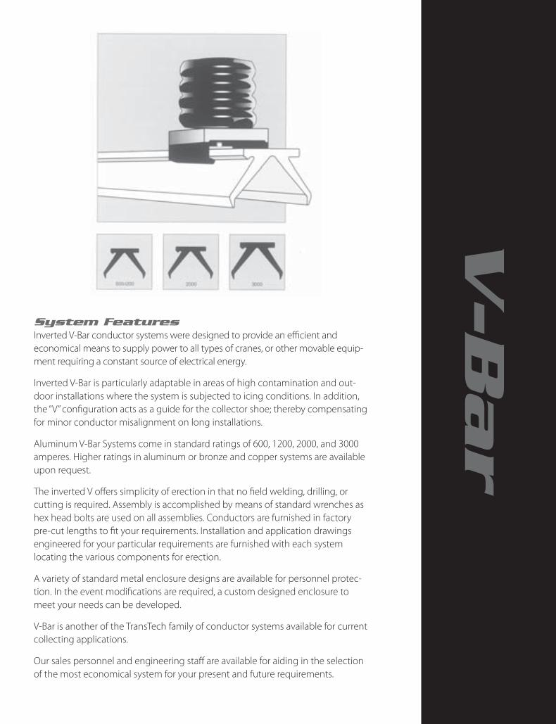
System Features Inverted V-Bar conductor systems were designed to provide an efficient and economical means to supply power to all types of cranes, or other movable equip-ment requiring a constant source of electrical energy.
Inverted V-Bar is particularly adaptable in areas of high contamination and out-door installations where the system is subjected to icing conditions. In addition, the “V” configuration acts as a guide for the collector shoe; thereby compensating for minor conductor misalignment on long installations.
Aluminum V-Bar Systems come in standard ratings of 600, 1200, 2000, and 3000 amperes. Higher ratings in aluminum or bronze and copper systems are available upon request.
The inverted V offers simplicity of erection in that no field welding, drilling, or cutting is required. Assembly is accomplished by means of standard wrenches as hex head bolts are used on all assemblies. Conductors are furnished in factory pre-cut lengths to fit your requirements. Installation and application drawings engineered for your particular requirements are furnished with each system locating the various components for erection.
A variety of standard metal enclosure designs are available for personnel protec-tion. In the event modifications are required, a custom designed enclosure to meet your needs can be developed.
V-Bar is another of the TransTech family of conductor systems available for current collecting applications.
Our sales personnel and engineering staff are available for aiding in the selection of the most economical system for your present and future requirements.
V-B
ar

VI-2
Aluminum Inverted V-Bar
ConductorThe V-Bar Conductor is designed for main runway or cross-travel applications. The recommended mounting is in the inverted V position (^) with the collectors underrun-ning. The conductors are normally mounted horizontally; however they can be vertically stacked. Phase spacing depends on conductor rating and collector selection.
The conductor is extruded from high conductivity alumi-num alloy in maximum 30 foot lengths. Shorter lengths are available (5 foot minimum) in one foot increments to coincide with runway length requirements.
A keying feature incorporated into the conductor configu-ration assures that all components are properly installed.
Standard Components - Aluminum V-Bar Conductor Systems
ComponentSystem Component Catalog Number
600 V-Bar 1200 V-Bar 2000 V-Bar 3000 V-Bar
Conductor* 98724-L* 98724-L* 94801-L* 93531-L*
Hanger with 5/8” Bolt 11455801 11455801 11468601 11449901
Splice Joint 95913 95912 94810 93536
Anchor 96426 96426 94807 96350
Feeder 96374 105454 96412 96367
Fixed Expansion Joint R.H. 96669 96497 96492 96493
Fixed Expansion Joint L.H. 96386 95930 94813 96303
Floating Assembly Joint 105547 99167 97545 106321
Isolating Joint 99910 99910 97963 109021
Collectors - Single Arm 99572 99572 99305 99305
Collectors - Double Arm 99573 99573 98986 98986
Collectors - Four Arm --- 99574 99542 99542
*”L” designates conductor length in feet. Standard length is 30’. An application of dry lubricant, Part No. 91592, is required on the conductor contact surface prior to use.
Oxide inhibiting paste, Part No. 90918, is required on all splice joints, feeders, and expansion joints.
Syst
em A
mpe
re
Ratin
g*
Cond
ucto
rCa
t. N
o.
A B C D
Cross Sectional
Area
Wei
ght
Lbs/
Ft.
DC
Resi
stan
ce
Ohm
s/ 1
000
ft. a
t 20
˚C.
AC
Resi
stan
ce
Ohm
s/ 1
000
ft. a
t 20
˚ C.
Self
Geo
met
ric
Dis
tanc
e d
s - I
nche
s
Sq. Inches CMx 106
600 98724-L 2 3/8” 2
1/16” 1/4” 3
3/8” 2.1 2.7 2.45 0.00705 0.0100 1.218
1200 98724-L 2 3/8” 2
1/16” 1/4” 3
3/8” 2.1 2.7 2.45 0.00705 0.0100 1.218
2000 94801-L 3” 2 1/8”
7/16” 3 5/8” 3.3 4.2 3.84 0.00452 0.00724 1.377
3000 93531-L 31/2” 3” 9/16” 51/8” 4.9 6.2 5.7 0.00305 0.00630 1.700
6000 Contact TransTech
*Ampere rating based on 30˚C rise over a 40˚ ambient.

VI-3
Aluminum Inverted V-Bar
Hanger AssemblyThe hanger assembly is used to support the conductor section with the aid of an insulator. The assembly consists of a molded casting with a 5/8-11 bolt for insulator mounting. Hangers are nylon coated to assure free movement of the conductor during expansion or contraction. Insulators are not furnished with the assembly.
Insulator selection depends on mounting clearances and operating voltage.
Syst
em Hanger Cat. No. A B C D E
Max
imum
Su
ppor
t Ce
nter
s Fe
et
Net
Wei
ght
Lbs.
600 11455801 3” 27/8” 215/16” 11/8” 215/16” 12’ .9
1200 11455801 3” 27/8” 215/16” 11/8” 215/16” 12’ .9
2000 11468601 3” 35/8” 35/16” 19/16” 35/16” 14’ 1.2
3000 11449901 3” 41/4” 49/16” 21/16” 49/16” 15’ 1.2
Insulated V-Bar SystemsAluminum systems, ratings 600 through 3000 amperes, are available with an extremely tough electrical grade thermoplastic red jacket suitable for indoor or outdoor installations.
The insulating jacket is normally installed during installation.
The insulation provides protection to personnel by enclosing the top and two sides of the conductor. Special covers are provided for splice joints, anchors, feeders, hangers, expansion joints, and isolating joints in order to provide a com-pletely insulated system.

VI-4
Aluminum Inverted V-Bar
Splice Joint AssemblyThe splice joint assembly connects electrically and mechanically, adjoining conductor sections without drilling or welding. The assembly consists of an extruded section containing bolts and a Belleville spring-type plate which insures positive electrical connection. All splice joints have a current capacity of greater than 100% when compared by the resis-tance test method (NEMA SGI-5.02) to an equal length of conductor.
Syst
em
Splic
e Jo
int
Cat.
No.
A B C D
Num
ber o
f Bol
ts
Ratin
g A
mpe
res
30˚C
. Ove
r 40˚
C.
Net
Wei
ght L
bs.
600 95913 8” 33/8” 21/4” 11/8” 4 600 2.0
1200 95912 12” 33/8” 21/4” 11/8” 6 1200 3.1
2000 94810 16” 35/8” 23/4” 19/16” 8 2000 7.8
3000 93536 18” 51/8” 39/16” 21/16” 8 3000 10.9
Anchor AssembliesAnchor assemblies are normally employed at one point in the system to provide a fixed point from which the conductor can expand or contract through the hangers. When expansion joints are employed additional anchors may be required.
The assembly consists of an extrusion with bolts that securely clamp it to the conductor and two studs for insulator mounting. An anchor is used in place of a hanger and requires two insulators which are not furnished with the assembly. Insulators should have the same height as the one used with the hanger assembly.
Insulator selection depends on the operating voltage of the system.
System Anchor Cat. No. A B C D E F Insulator
Bolt
Net Weight
Lbs.
600 96426 201/4” 3 3/8” 23/16” 1 1/8” 61/4” 7” 5/8 “-11 UNC 4.3
1200 96426 201/4” 3 3/8” 23/16” 1 1/8” 61/4” 7” 5/8 “-11 UNC 4.3
2000 94807 22” 35/8” 27/8” 19/16” 61/4” 77/8” 5/8 “-11 UNC 7.5
3000 96350 20” 51/8” 39/16” 21/16” 61/4” 67/8” 5/8 “-11 UNC 9.8

VI-5
Aluminum Inverted V-Bar
Isolating Joint AssemblyThe isolating joint assembly is used to insulate adjacent conductor sections from each other without interfering with collector travel. It allows portions of the system to be electrically disconnected while operations continue on other live sections. At installations where more than one crane will be operated on a single conductor system, the isolating joint is used to create maintenance and repair bays. The isolating joint may be inserted at any point on the system in place of a standard splice joint assembly. When installed, it assures correct alignment between adjacent conductors. There are two methods of feeding the conductor system at isolation joints. (See Diagram.)
Each side can be fed individually through adequate safety switches or the isolation joint can be by-passed with the use of feeder assemblies and a suitable disconnect switch.
Syst
em
Isolating Joint
Cat. No.A B C D E F
Net Weight
Lbs.
600 99910 25” 33/8” 329/64” 11/8” 101/2” 4” 5.0
1200 99910 25” 33/8” 329/64” 11/8” 101/2” 4” 5.0
2000 97963 29” 35/8” 41/32” 19/16” 121/2” 4” 11.1
3000 109021 29” 51/8” 51/16” 21/16” 121/2” 4” 14.5
Floating Expansion JointFloating expansion joints are used only when the expected expansion exceeds the fixed expansion joint capability.
The assembly is normally installed between anchor assemblies across a building expansion joint.
The assembly consists of three extruded sections, one short length of conductor, flexible copper shunts, bi-metal plates, connecting links, and bolts. No insulators are required.
Conductor gap setting is based on both the ambient temperature at the time of installation and the expected temperature variation to which the system will be exposed.
System
Expa
nsio
n Jo
int C
at.
No
Max
imum
Expa
nsio
n (2
X) in
ches
A B C D E
Rating Amperes
30˚C Over 40˚C
Net Wt
Lbs.
600 105547 5” 56” 4” 27/8” 11/8” 12” 600 26.81200 99167 5” 56” 4” 33/8” 11/8” 12” 1200 37.62000 97545 5” 56” 47/8” 37/8” 19/16” 12” 2000 71.83000 106321 5” 56” 51/2” 41/8” 21/16” 12” 3000 84.8

VI-6
Aluminum Inverted V-Bar
Fixed Expansion JointFixed expansion joints are sometimes required when the system crosses a building expansion joint or when the runway is excessively long. In addition, extreme variations in temperature along the length of the runway warrant the possible use of an expan-sion joint assembly. Recommended maximum system lengths with center anchor are shown in adjoining chart. Longer systems should include expansion joints.
The assembly consists of two extrusions, shunts, bolts, and two insulator mounting studs. The insula-tor side of the assembly is the fixed section and acts as an anchor. The other section is bolted to the conductor and with the aid of flexible copper shunts maintains electrical continuity across the conductor gap. Shunts are separated from the aluminum with bi-metal plates. Conductor gap setting is based on both the ambient temperature at the time of installa-tion and the expected temperature variation to which the system will be exposed.
There are two assemblies-right hand and left hand. This is due to the aligning key on the conductor. Normally the key side of the conductor is located on the side nearest the centerline of the crane runway. When standing in the center of the runway facing the conductor system, a right hand assembly allows conductor expansion to the right, a left hand assem-bly to the left.
Syst
em
Expansion Joint Cat. No
Max
imum
Expa
nsio
n (X
) in
ches
A B C D EInsulator Bolt Rating
Amperes 30˚C
Over 40˚C
Recommended Max. System Length
Net Wt
Lbs.
Ft. Center Anchor
Segment Between Expansion Joints
Right Hand*
Left Hand Qty Size Indoor Outdoor Indoor Outdoor
600 96669 96386 21/2” 57” 33/8” 27/8” 11/8” 141/2” 2 5/8-11 UNC 600 600 500 300 250 14.91200 96497 95930 21/2” 57” 33/8” 33/8” 11/8” 141/2” 2 5/8-11 UNC 1200 600 500 300 250 19.32000 96492 94813 21/2” 63” 35/8” 37/8” 19/16” 181/2” 2 5/8-11 UNC 2000 800 700 400 350 39.23000 96493 96303 21/2” 63” 51/8” 41/8” 21/16” 181/2” 2 5/8-11 UNC 3000 1000 800 450 400 51.2

VI-7
Aluminum Inverted V-Bar
System Feeder Cat. No A B C D
Feeder Lug Provision Rating Amperes 30˚C Over 40˚C
Net Wt Lbs.Quantity Bolt Size Bolt Spacing “E”
600 96374 163/4 “ 33/8 “ 23/16 “ 11/8 “ 1 1/2-13 UNC 13/4 “ 600 3.7
1200 105454 203/4 “ 33/8 “ 23/16 “ 11/8 “ 2 1/2-13 UNC 13/4 “ 1200 4.72000 96412 193/4 “ 35/8 “ 27/8 “ 19/16 “ 2 1/2-13 UNC 13/4 “ 2000 7.13000 96367 203/4 “ 51/8 “ 31/2 “ 21/16 “ 3 1/2-13 UNC 13/4 “ 3000 10.7
Feeder AssemblyThe feeder provides the electrical connection from the power source to the conductor system. It may be located at any point within the system, preferably near the center. This location reduces the effective system length, which in turn reduces voltage drop. No field drilling or welding is required for installation. Feeders should be located no closer than six inches from the nearest component to prevent conductor lock-up during expansion or contraction. The feeder consists of an extrusion with bolts that clamp the assembly securely to the conductor. Bi-metal plates are provided to prevent electro-lytic action when using bronze or copper lugs.
Provisions are made for one, two, or three feeder lugs. Lugs are not furnished with the assembly except by request at additional cost. Feeders are tapped for standard NEMA-type lugs.
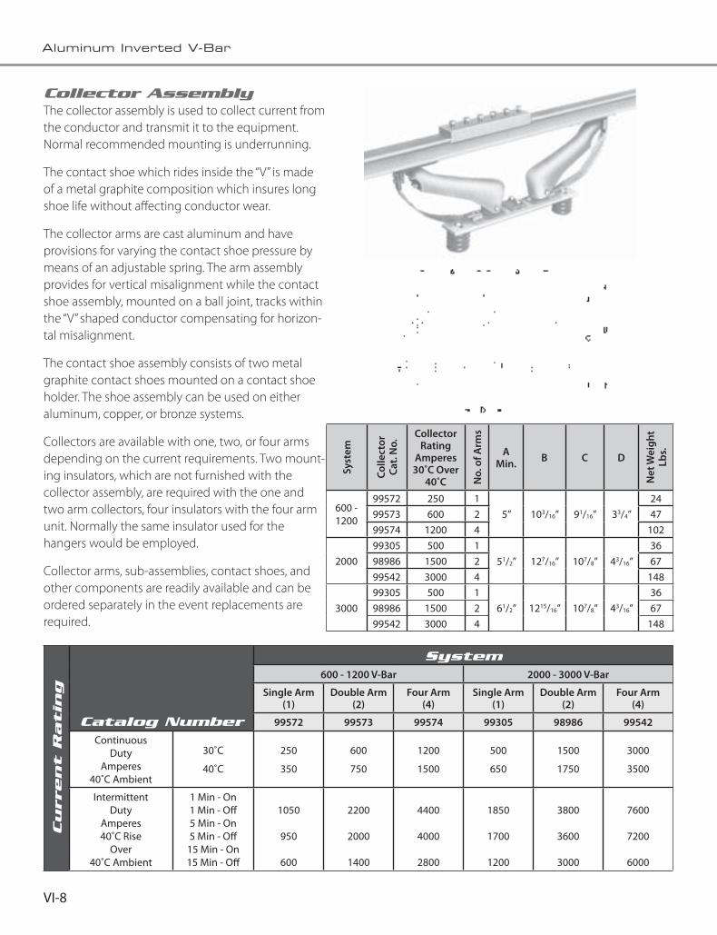
VI-8
Aluminum Inverted V-Bar
Collector Assembly The collector assembly is used to collect current from the conductor and transmit it to the equipment. Normal recommended mounting is underrunning.
The contact shoe which rides inside the “V” is made of a metal graphite composition which insures long shoe life without affecting conductor wear.
The collector arms are cast aluminum and have provisions for varying the contact shoe pressure by means of an adjustable spring. The arm assembly provides for vertical misalignment while the contact shoe assembly, mounted on a ball joint, tracks within the “V” shaped conductor compensating for horizon-tal misalignment.
The contact shoe assembly consists of two metal graphite contact shoes mounted on a contact shoe holder. The shoe assembly can be used on either aluminum, copper, or bronze systems.
Collectors are available with one, two, or four arms depending on the current requirements. Two mount-ing insulators, which are not furnished with the collector assembly, are required with the one and two arm collectors, four insulators with the four arm unit. Normally the same insulator used for the hangers would be employed.
Collector arms, sub-assemblies, contact shoes, and other components are readily available and can be ordered separately in the event replacements are required.
Syst
em
Colle
ctor
Ca
t. N
o.
Collector Rating
Amperes 30˚C Over
40˚C No.
of A
rms
A Min. B C D
Net
Wei
ght
Lbs.
600 - 1200
99572 250 15” 103/16” 91/16” 33/4”
2499573 600 2 4799574 1200 4 102
200099305 500 1
51/2” 127/16” 107/8” 43/16”36
98986 1500 2 6799542 3000 4 148
300099305 500 1
61/2” 1215/16” 107/8” 43/16”36
98986 1500 2 6799542 3000 4 148
Current R
atin
g
Catalog Number
System 600 - 1200 V-Bar 2000 - 3000 V-Bar
Single Arm (1)
Double Arm (2)
Four Arm (4)
Single Arm (1)
Double Arm (2)
Four Arm (4)
99572 99573 99574 99305 98986 99542
ContinuousDuty
Amperes40˚C Ambient
30˚C
40˚C
250
350
600
750
1200
1500
500
650
1500
1750
3000
3500
IntermittentDuty
Amperes40˚C Rise
Over40˚C Ambient
1 Min - On1 Min - Off5 Min - On5 Min - Off
15 Min - On15 Min - Off
1050
950
600
2200
2000
1400
4400
4000
2800
1850
1700
1200
3800
3600
3000
7600
7200
6000

VI-9
Aluminum Inverted V-Bar
No. 99572
No. 99573
No. 99574No. 99305
No. 98986
No. 99542

VI-10
Aluminum Inverted V-Bar
System LayoutThe first step in preparing a system layout is to select the proper conductor rating required for the installation. Once the conductor size has been selected, the hanger sup-port-centers for that particular size conductor may be selected from the chart shown with the hanger assembly on Page 3. In order to determine if an expansion joint is required, refer to the fixed expansion joint chart. In the majority of installations none is required. In the event a building expansion joint occurs near mid-point in the system, a floating expansion joint assembly should be considered. Where no expansion joints are required, the system should be anchored approximately in the center. Anchor assemblies are shown on Page 4.
The feeder assembly, if possible, should be located near the center of the system.
This reduces the effective systems length “L” which is used in the formula to determine the proper conductor amperage rating. Feeders with provision for one to three lugs may be selected from the feeder assemblies. Careful attention must be given to mechanical clearance be-tween components. All splice joints, expansion joints, feeders, and isolation joints must be kept at a minimum of six (6) inches away from the nearest insulated hanger to insure free sliding of the conductor through the hanger
The following symbols and example layouts are intended for a guide in preparing a layout. However, upon request, TransTech will prepare an application layout to fit your requirements.
SYSTEM A —No Expansion Joint — Center Anchored
SYSTEM B —Fixed Expansion Joint
SYSTEM C —Floating Expansion Joint
SYSTEM D —Isolating Joint
Our prepared application layout drawings will be submitted for each installation.

VI-11
Aluminum Inverted V-Bar
TECHNICAL DATA
CONDUCTOR SIZE CALCULATION
There are two accepted methods of determining the maximum ampere demand of one or more cranes on a single runway.
Method AMaximum load equals the sum of all main and auxiliary hoist H.P. plus one-half (1/2) the sum of all bridge motor and trolley H.P.
Method BMaximum load equals one-half (1/2) the sum of all motor and accessory H.P.
CALCULATION
Load H.P. (Method A or B) x amperes per H.P. (Table A) = maximum ampere demand.
Maximum ampere demand x crane factor (Table C) = adjusted maximum ampere demand.
VOLTAGE DROP CALCULATIONSymbolsVL = Line Voltage at Feeder (Source).
VD = Voltage Drop.
I = Load Amperes.
L = Effective System Length in Feet. Maximum distance from feeder to end of system.
RDC = D. C. Resistance-ohms/1000 feet.
K = Voltage Drop Multiplier (Table B). A factor derived from tests which accounts for variables such as A. C. resistance, inductive reactance, power factor, phase spacing, and conductor shape factors.
Formulas
Direct Current
VD = ILRDc 500
Alternating Current - Three Phase (80 percent Power Factor-Flat Spacing) VD=I L K (Line to Line*)
*For Line to Neutral Voltage Drop divide by 1.73.
Voltage Regulation % Regulation = VD x 100 VL-VD
Example
Length of runway, 400 feet, operating on 440 volts, 3 phase, 60 cycle, phase spacing 6 inches, feeder location-center of runway, one crane on runway. By Method “A,” the maximum ampere demand would be calculated as follows:
ACTUAL CALCULATED
H.P. H.P.
Main Hoist 200 200Auxiliary Hoist 250 250Bridge (2 motors at 150 each) 300 150Trolley 60 30 Total 280 H.P.
From Table A multiplier is 1.5. 1.5 x 630 H.P. = 945 maxi-mum ampere demand. Based on a 30˚C rise over 40˚C ambient, you could select the 1200 aluminum V-Bar series for this application.
From Table B, the 1200 Series with a 6 inch phase spacing has a K multiplier of 57.60 x 10˚ - therefore:
VD (Voltage Drop) = I x L x K
VD = 945 x 200 x (57.60) (10-6)
VD = 10.8 volts
% Regulation = VD x 100 VL-VD
Regulation = 10.8. x 100 = 2.5% 440-10.8

VI-12
Aluminum Inverted V-Bar
Expansion Joint Gap Setting ChartThe gap setting chart is to be used to establish the expansion joint gap setting at the time of installation.
The chart should be used according to the following procedure:
(a) Determine local ambient temperature range. Example -20 to 100°F
(b) On A scale, write in the highest expected ambient at point X and decrease in 10 degree increments to the lowest expected ambient.
(c) Determine the ambient temperature at time of gap setting. From the existing ambient temperature, A’ scale, read across to the curve and down to the gap setting. Adjust gap accordingly.
Note: The system should be checked at maximum and minimum tempera-tures as they first occur. Gap settings will require adjustment if they open greater than maximum at the low ambient, or if they are completely closed at the high ambient.
TABLE A Amperes Per Horsepower Conversion
Current Voltage Multiplier*
D.C.115230600
84
1.6
A.C. (3ø) 110220440550
2300
7.03.01.51.2
0.25
A.C. (2ø) 110220440550
2300
6.02.61.31.1
0.21
*Average conversion factors calculated from National Electric Code FulI Load Current Motor Charts. Motors built for especially low speeds or high torques may require more running current. In which case, name-plate or design current ratings should be used.
TABLE C CRANE FACTOR (CF)
Current Multiplier*
1 1
2 0.95
3 0.91
4 0.87
5 0.84
*In the event there are two or more cranes operating on the same load side of the feed-er, the multiplying factors shown in Table C would be applied to the maximum ampere
demand calculated by Method A or B.
TABLE B
V-Bar Conductor Series
“K”-Voltage Loss Multiplier X 10-6
Conductor Phase Spacing — Inches5 51/2 6 61/2 7 8 9 10 11 12
600 53.5 55.4 57.6 59.5 61.0 63.7 66.1 68.9 71.5 74.01200 53.5 55.4 57.6 59.5 61.0 63.7 66.1 68.9 71.5 74.02000 - 50.3 51.8 53.6 55.2 58.1 61.0 63.4 65.8 67.73000 - - - 43.2 45.4 49.6 53.5 56.7 59.3 61.1

VI-13
Aluminum Inverted V-Bar
GENERAL SPECIFICATIONSConductor-Collector SystemThe conductor-collector system shall be of the V-Bar Alumi-num Series as manufactured by TransTech.
Each system shall consist of necessary conductor sections, hanger supports, insulators, anchor supports, expansion joints, collectors, and/or special components as determined from plans and specifications. The conductor section shall be one-piece aluminum of “V” beam configuration with an inverted V contact surface. The conductor aluminum alloy shall have a minimum conductivity of 56% lACS and a current carrying capacity of (600) (1200) (2000) (3000) amperes baaed on a 30°C rise over 40°C ambient when operating in still, but unconfined, air. The conductor shall have sufficient thermal capacity to withstand a 300% overload for intermittent duty cycles.
The conductor hangers shall be made from an aluminum casting and shall be nylon coated to provide free conductor movement through the hanger, accommodating expansion or contraction. Splice joints, anchors, feeders, and expansion joints shall be provided as required. These elements shall be manufactured from aluminum extrusions. The design shall be such that only bolting to the conductor is required; no drilling or welding of the rail at erection shall be necessary.
The splice joints, feeders, and expansion joints shall have a current capacity of greater than 100 percent when com-pared, by the resistance test method (NEMA SGI-5.02), to an equal length of conductor.
The temperature rise of the accessory components shall not exceed the 30˚C rise of the conductor with which they are used.
InsulatorsThe insulators shall be molded from fiber glass reinforced polyester material, as manufactured by TransTech.
The insulator shall have a dew flashover strength when tested per ABA Specification C29.1 of at least four (4) times normal system voltage.
The basic insulator material shall exhibit the following minimum performance levels when tested in accordance with American Society of Testing Materials Specifications. (ASTM).
Property Minimum ASTM No.
Dielectric Strength 420VPM D149
Arc Track Resistance 190 Seconds D495
Track Resistance Inclined Plane, Min. Over 1200 D2303
Flammability Self-Exting. D635
Heat Distortion Temp. @ 264 psi 595˚F D648
Dissipation Factor, 60HZ .042 D150
Impact Strength, Ft-Lbs. 4.5 D256
Flexural Strength, psi 18,000 D790
CollectorsThe collectors shall have a current carrying capacity of (250) (500) (600) (1200) (1500) (3000) amperes based on a 300˚C rise over a 40°C ambient when operated in still, but unconfined air. The collectors shall have sufficient thermal capacity to withstand a 300% overload for intermittent duty cycles. The collectors shall incorporate means of adjusting the contact pressure. The collector shall consist of a high strength aluminum arm which covers the collector spring.

VI-14
Aluminum Inverted V-Bar

System Features TransTech’s HV-Bar conductor system combines the economy of the lower amp H-Bar systems with the collector tracking and weather protection benefits of the V-Bar system. The HV-Bar conductor is rigid aluminum extruded from 6101-T6 alloy. The HV-Bar system offers simplicity in installation and requires no field welding, drilling or cutting. Assembly is accomplished by means of standard wrenches as hex head bolts are used on all assemblies. Conductors are furnished in factory pre-cut lengths to fit your requirements. Installation and layout drawings showing the location of all components are engineered for your particular requirements and are furnished with each system.
Component Part Number
Conductor 750 Amps 114546-30
Hanger With 3/8" Bolt 106125
Splice Joint 106130
Anchor 106140
Feeder (1-Lug Provision) 106170
Feeder (2-Lug Provision) 106171
Fixed Expansion Joint 106150
Isolation Joint 106145-02
Insulator 15-51-21 94551-21
Insulator With Petticoat 94571-21
Collector (2) Arm 114563
HV-B
ar

VII-2
Aluminum Inverted HV-Bar
ConductorThe HV-Bar conductor is designed for main runway or cross-travel applications. The recom-mended mounting is in the inverted V position with the collectors in the under-running position. The conductors are normally mounted horizon-tally with a minimum phase spacing 31/2”. The conductor is extruded from high conductivity aluminum alloy 6101-T6 and supplied in 30 foot lengths. Shorter lengths can be supplied in one foot increments to match your runway length. The HV-Bar conductor part number is 114546-L where “L” designates the conductor length in feet. Part number 114546-30 is the standard 30 foot long conductor .
System Amperage
Rating
Catalog Number
Area Sq.
Inches
Weight Lbs/Ft
D.C. Resistance
ohms/1000 Ft
A.C. Resistance
ohms/1000 Ft
750 114546-”L” 0.82 0.96 0.018 0.025
“L” Designates conductor length in feet. Standard length Is 30 feet.
Hanger AssemblyThe hanger assembly is used with Red-Poly insulators to provide mechanical support and electrical insulation for the conductor system. Hangers are located on five foot spacing. The hanger is made of cast aluminum, nylon coated to assure free sliding through the hanger casting during expansion and contraction of the con-ductor system. Conductor “lock-up” has been eliminated by the free sliding design, provided components like feeder assemblies and isolation joints are located at least 6” away from adjacent hangers.
Splice Joint AssemblyThe splice joint assembly connects and aligns adjoining conductor sections without drilling or welding. Simplicity of the assembly requires only standard hex wrenches. Bolts secure a spring type, aluminum plate which insures the electrical connection. The aluminum splice joint has an electrical efficiency of greater than 100% when compared by the resistance method to an equal length of conductor. Torque 3/8 - 16 aluminum hex bolts provided with the spice joint assembly to 12 ft-Ibs for proper installation.

VII-3
Aluminum Inverted HV-Bar
Feeder AssemblyThe feeder assembly provides the electrical connection from the power source to the conductor. It may be located at any point on the conductor system. The feeder is normally located at the center of the conductor system. Long systems may require two or more feeders located near the ends of the system to reduce voltage drop. Feeder assemblies must have clearance from adjacent hangers for expansion and contraction of the conductor system. Feeder cables must have enough flex to accommodate conductor movement over the expected operat-ing temperature range. Provisions are made for one or two NEMA standard (13/4”) terminal lugs per feeder assembly. Terminal lugs are not included with the feeder assembly, but can be provided to match your cable size. Bi-metal plates are provided with each feeder assembly to prevent corrosion between bronze or copper terminal lugs and aluminum extrusions.
Anchor AssemblyThe anchor assembly is used at one location in the conductor system to secure the conductors to a fixed point from which the conductors expand or contract through the hanger castings. The anchor assembly consists of an aluminum extrusion with aluminum hex bolts that securely clamp to the conductor. The anchor assembly replaces a hanger assembly in the system and requires two mounting brackets and two mold-ed insulators.

VII-4
Aluminum Inverted HV-Bar
Isolation Joint AssemblyThe isolation joint assembly is used to insulate one section of the conductor from an adjacent section without interfering with collector travel. It allows portions of the system to be electrically disconnect-ed while operations continue on the other sections of the conductor system. When more than one crane is operating on the conductor system, the isolation joint is used to create a maintenance area or repair bay. The isolation joint can be inserted at any place in the conductor system. Usually the isolation joints are located 30 feet from each end and replace the last splice assembly on each end of the conductor system. Normally the maintenance area or repair bay is fed electrically through a disconnect switch attached to feeder assemblies on either side of the isolation joint assembly. This arrangement allows for electrical power to be disconnected and “locked out” at a location near the maintenance area or repair bay.
Fixed Expansion Joint AssemblyThe expansion joint assembly is necessary on long runways where expansion and contraction of the conductors exceed limits set by TransTech. Normal indoor installations do not require expansion joints if the temperature ranges do not exceed 80 degrees F. Conductor systems longer than 500 feet or systems with extreme temperature variations may require expansion joints.
The conductor gap setting is based on the ambient temperature at the time of installation and the expected temperature variation to which the system will be exposed. At the coolest ambient temperature the gaps must not exceed the maximum expansion gap setting of 11/2 inches. At the hottest ambient and operating temperatures the expansion gap should be nearly closed. Electrical continuity during expan-sion and contraction is maintained through flexible copper shunts. Copper shunts are separated from the aluminum extrusion with bi-metal plates.
Mounting the fixed expansion joint assembly re-quires two mounting brackets and two molded insulators.

VII-5
Aluminum Inverted HV-Bar
Mechanical Properties 9455121 9457121
Tensile Strength 3,500 pounds 3.500 pounds
Cantilever Strength 3,000 Inch-pounds 3,000 Inch-pounds
Torsional Strength 600 Inch-pounds 600 Inch-pounds
Weight 0.46 pounds 0.61 pounds
Electrical Properties 9455121 9457121
Dielectric Strength - Dry 38 kV 38 kV
Dew Flashover Strength 15 kV 22 kV
Creep Distance 2.5 Inches 3.6 Inches
Double Arm Collector HV-Bar Catalog Number - 114563
Collector Ratings
Temp. Rise Current Rating
30˚ C 400 Amps
40˚ C 500 Amps
Note: Collector Horizontal Misalignment is + 2”
9455121
9457121
Red-Poly InsulatorThe Red-Poly insulators are molded fiberglass reinforced polyester material with superior mechani-cal strength, excellent electrical characteristics, flame retardant, self extinguishing and track resistant. Red-Poly insulators are manufactured in a variety of styles and heights to match your voltage and appli-cation requirements. Red-Poly insulator 15-51-21 is used for most applications.

VII-6
Aluminum Inverted HV-Bar

VII-7
Aluminum Inverted HV-Bar
TECHNICAL DATA
MAXIMUM AMPERE DEMAND
Maximum ampere demand equals the sum of all main and auxiliary hoist H.P. plus (1/2) the sum of all bridge and trolley motor H.P.
CALCULATION
Load H.P. x amperes per H.P. (Table A) = maximum ampere demand.
Maximum ampere demand x crane factor (Table C) = adjusted maximum ampere demand.
VOLTAGE DROP CALCULATIONSymbolsDV = Line Voltage at Feeder (Source).
V = Voltage Drop.
I = Load Amperes.
L = Effective System Length in Feet. Maximum distance from feeder to end of system.
RDC = D. C. Resistance-ohms/1000 feet.
K = Voltage Drop Multiplier (Table B).
Formulas
Direct Current
DV = I x L x RDC 500
D.C. 3 phase (80% power factor) DV = I x L x K (Line to Line)
Example
Length of runway, 400 feet, operating on 440 volts, 3 phase, 60 Hz, phase spacing 5 inches, feeder location-center of runway, one crane on runway. Maximum ampere demand would be calculated as follows:
ACTUAL H.P CALCULATED H.P
Main Hoist 200 200Auxiliary Hoist 150 150Bridge 200 100Trolley 50 25 Total 475
From Table A multiplier is 1.5. 1.5 x 475 H.P. = 713 ampere
From Table B, the (phase spacing of 5”)
K = 81 x 10-6
DD = 713 x 200 x 81 x 10-6
DD = 11.55
Regulation = DD x 100 V-DD
Regulation = 11.55 x 100 440-11.55
Regulation = 2.7%
TABLE C
CraneFactor
Cranes Per Runway
Multiplying Factor
1 1
2 0.95
3 0.91
4 0.87
TABLE B
HV-BarK Values x 10-6
Phase Spacing In Inches31/2 4 41/2 5 51/2 6 61/2 7 71/2 8 9
750A 72 75 78 81 83 85 87 89 91 93 95
TABLE ACurrent Voltage Multiplier
Amperes Per Hoursepower
Conversion Table
D.C. 230 VD.C. 600 V
4.01.6
A.C. 220 VA.C. 440 V
3.01.5

VII-8
Aluminum Inverted HV-Bar

System Features• 1750,2500,4000and6000amp
capacitiesavailable• ACorDCvoltagesupto4160V
basedoninsulatorselection• 30footstandardraillengths.
customlengthsavailable• Compatiblewiththecorre-
sponding'H'and'HC'conduc-torbarsystemcomponents
• Suitablefortop-running,under-runningandside-run-ninginstallations,withbothtrackingandnon-trackingcollectors
HJ Bar DimensionsSeries A (in.) B (in.) Wt./Ft.
1750 2.50 2.25 7.3
2500 3.25 3.75 9.5
4000 4.00 4.50 12.2
6000 5.00 5.50 16.4
Hybrid Aluminum/Stainless Steel Conductor SystemHJ-Barcombinesthehighconductivityofaluminumwiththecorrosionresistanceanddurabilityofastainlesssteelcapintoasingleconductorbar.Unlikeotheraluminum/steeldesignsthatusealuminumconductorsboltedtostandardsteelrailtoimproveelectricalperformance,HJ-Baroptimizesthealuminum/steelelectricalinterfacethroughapropri-etarymanufacturingprocessthatprovidescontinuouscontactpressurealongtheentirelengthoftherail.Thisdesignresultsinalightweight,durableandlow-maintenanceconductorrail.Systemsareavailablewithratingsof1750,2500,4000and6000amperes.Largersystemsareavailableuponrequest.
Features• Patentedmanufacturingprocessensureslowelectricalresistancebetweenaluminum
andstainlesssteelcomponentsthroughcontinuouscontactpressure• Fullrangeofstandardcomponentsincludinghangers,anchors,feeders,splicejoints,
expansionjoints,isolationjointsandcollectorassemblies• Service-provenstainlesssteelcapdesignyieldshighstrengthwithoutshiftingor
peelingfromthealuminumbar,evenunderextremeloads• Hard3/16"thickstainlesssteelrunningsurfaceforextendedlifeundercontinuoususe• Systemsareengineeredtocustomerspecifications,includingsystemlayoutand
installationsupport• Nocleaningorconditioningoftheconductorsurfacerequiredforinfrequentuse
situations
Project Engineering and On-Site Installation SupportTransTech'sengineerscustom-configureourproductsandsystemstomeeteachcustom-er'suniqueapplicationrequirements.Weprovideon-sitetechnicalinstallationsupportandlayoutdrawingstoourcustomersandtheirinstallationteams.
HJ-B
ar

VIII-2
Aluminum/Stainless Steel HJ-Bar
ConductorTheAluminum/StainlessSteelHJ-BarConductorisdesignedformainrunwayorcrosstravelapplica-tions.Itmaybemountedwiththeconductorsurfaceinanyplane.Underorsiderunningarethemostcommonmountingpositions.The"H"configurationwasselectedforitsstructuralstrengthallowingmaximumhangerspacing,therebyreduc-inginstallationcosts.Theconductorissuppliedinmaxi-mum30footlengths.Shorterlengthsareavailable(5footminimum)inonefootincre-mentstocoincidewithyourrunwaylengthrequirements.
STANDARD COMPONENTS — System - SeriesComponent 1750 Amps 2500 Amps 4000 Amps 6000 Amps
Conductor Bar 106199 300050 300075 300100
Hanger Assembly 106126 106127 106128 106129
Hanger Assembly (dual insulator) 107826 107827 107828 107829
Splice Joint Assembly (friction) 106132 106134 106136 106137
Splice Joint Assembly (bolt thru) n/a 300055 300080 300105
Anchor Assembly (friction) 106141 106142 106143 106144
Anchor Assembly (bolt thru) n/a 300070 300095 300120
Isolating Joint Assembly (friction) 106146 106147 106148 106149
Isolating Joint Assembly (bolt thru) n/a 300060 300085 300110
Fixed Expansion Joint 106152 106153 106155 106157
Feeder Assembly (friction) 106173 106174 107949 106178
Feeder Assembly (bolt thru) n/a 300065 300090 300115
Field Drilling Jig n/a 300051 300076 300101
Syst
em A
mpe
re
Ratin
g
Cond
ucto
rCa
t. N
o.
A B C
Cross Sectional
Area
Wei
ght
Lbs/
Ft.
DC
Resi
stan
ce
Ohm
s/ 1
000
ft. a
t 20
˚C.
AC
Resi
stan
ce
Ohm
s/ 1
000
ft. a
t 20
˚ C.
Self
Geo
met
ric
Dis
tanc
e d
s - I
nche
s
Current Rating Amperes-Continuous
40˚ C. Ambient
Sq. Inches MCM 30˚ C. Rise
1750 106199 3.56 2.51 2.25 3.3 4250 7.3 0.0045 0.0069 1.357 1750
2500 300050 3.56 3.25 3.75 5.2 6650 9.5 0.0028 0.0051 1.680 2500
4000 300075 3.56 4.00 4.50 7.5 9590 12.2 0.0020 0.0040 2.003 4000
6000 300100 3.56 5.00 5.50 11.1 14120 16.4 0.0013 0.0031 2.411 6000

VIII-3
Aluminum/Stainless Steel HJ-Bar
Hanger AssemblyThehangerassemblyisusedtosupporttheconductorsectionwiththeaidofaninsulator.Thehangerismadeofcastaluminum,nyloncoatedtoassurefreeslidingduringexpansionandcontractionoftheconductorthroughthehanger.Conductor“lock-up”hasbeeneliminatedbythisaddedfeature.Thehanger,liketheconductor,maybemountedinanyplane.
Insulatorselectiondependsontheoperatingvoltageofthesystemandthehangerboltsize.
Dual-Insulatorsupportsalsoavailable.
Syst
em
Han
ger
Cat.
No.
A B C
Insu
lato
r Bo
lt
Max
imum
Su
ppor
t Ce
nter
s Fe
et
Net
Wei
ght
Lbs.
1750 106126 2 11/16 27/85/8-11 UNC 12 .31
2500 106127 3 13/8 45/85/8-11 UNC 14 1.2
4000 106128 31/2 17/8 57/85/8-11 UNC 16 1.6
6000 Consult TransTech
Splice Joint AssemblyThesplicejointassemblyconnectsandalignsadjoiningconductorsectionswithoutdrillingorwelding.Simplicityoftheassemblyrequiresonlystandardhexwrenches.BoltssecureaBelleville-spring-type,aluminumplatewhichinsurestheelectricalconnection.
Thealuminumsplicejointhasanelectricalefficiencyofgreaterthan100%whencomparedbytheresistancetestmethod(NEMASG1-5.02)toanequallengthofconductor.
Boltthroughsplicejointsalsoavailable.
Syst
em
Splic
e Jo
int
Cat.
No.
A B C D
Num
ber
of B
olts
Ratin
g
Am
pere
s
30˚C
. O
ver 4
0˚C.
Net
W
eigh
t Lb
s.
1750 106132 10 11/16 27/85/8 4 1750 2.8
2500 300055 Consult TransTech
4000 300080 Consult TransTech
6000 300105 Consult TransTech
PRO
DU
CED
BY
AN
AU
TOD
ESK
ED
UC
ATI
ON
AL
PRO
DU
CT
PRODUCED BY AN AUTODESK EDUCATIONAL PRODUCT
PRO
DU
CED
BY A
N A
UTO
DESK
EDU
CA
TION
AL PR
OD
UC
T
PRODUCED BY AN AUTODESK EDUCATIONAL PRODUCT
PRO
DU
CED
BY
AN
AU
TOD
ESK
ED
UC
ATI
ON
AL
PRO
DU
CT
PRODUCED BY AN AUTODESK EDUCATIONAL PRODUCT
PRO
DU
CED
BY A
N A
UTO
DESK
EDU
CA
TION
AL PR
OD
UC
T
PRODUCED BY AN AUTODESK EDUCATIONAL PRODUCT

VIII-4
Aluminum/Stainless Steel HJ-Bar
Anchor AssemblyAnchorassembliesareemployedatoneormorepointsinthesystemtosecuretheconductortoafixedpointfromwhichtheconductorcanexpandorcontractthroughthehangers.
Theassemblyconsistsofanaluminumextrusionwithboltsthatsecurelyclamptotheconductor.
Ananchorassemblyreplacesahangerinthesystemandrequirestwomountinginsulators.
Insulatorselectiondependsontheoperatingvoltageofthesystemandtheanchorboltsize.
Boltthroughanchorassem-blyalsoavailable.
PRO
DU
CED
BY
AN
AU
TOD
ESK
ED
UC
ATI
ON
AL
PRO
DU
CT
PRODUCED BY AN AUTODESK EDUCATIONAL PRODUCT
PRO
DU
CED
BY A
N A
UTO
DESK
EDU
CA
TION
AL PR
OD
UC
T
PRODUCED BY AN AUTODESK EDUCATIONAL PRODUCT
Isolating Joint AssemblyTheIsolatingJointAssemblyisusedtoinsulateadjacentconductorsectionsfromeachotherwith-outinterferingwithcollectortravel.Itallowsportionsofthesystemtobeelectricallydisconnectedwhileoperationscontinueonotherlivesections.Atinstallationswheremorethanonecranewillbeoperatedonasingleconductorsystem,theisolatingjointisusedtocreatemaintenanceandrepairbays.Theisolatingjointmaybeinsertedatanypointonthesysteminplaceofastandardsplicejointassem-bly.Wheninstalled,itassurescorrectalignmentbetweenadjacentconductors.Therearetwometh-odsoffeedingtheconductorsystematisolationjoints.(SeeDiagram).
Eachsidecanbefedindividuallythroughadequatesafelyswitchesortheisolationjointcanbeby-passedwiththeuseoffeederassembliesandasuitabledisconnectswitch.
PRO
DU
CED
BY
AN
AU
TOD
ESK
ED
UC
ATI
ON
AL
PRO
DU
CT
PRODUCED BY AN AUTODESK EDUCATIONAL PRODUCT
PRO
DU
CED
BY A
N A
UTO
DESK
EDU
CA
TION
AL PR
OD
UC
T
PRODUCED BY AN AUTODESK EDUCATIONAL PRODUCT
Syst
em Anchor Cat. No. A B C D E
Insu
lato
r Bo
lt
Net Weight
Lbs.
1750 106141 21 41/2 27/8 7 3/85/8
5/8 -11 UNC 5.2
2500 300070 Consult TransTech
4000 300095 Consult TransTech
6000 300120 Consult TransTech
Syst
em Isolating Joint Cat. No. Ty
pe A B C D ENet
Weight Lbs.
1750 106146 I 21 11/16 27/8 81/2 2 4.6
2500 300060 Consult TransTech
4000 300085 Consult TransTech
6000 300110 Consult TransTech

VIII-5
Aluminum/Stainless Steel HJ-Bar
Fixed Expansion JointFixedexpansionjointsaresometimesnecessarytoaccommodatebuildingorsupportsstructureexpansion.Normalindoorinstallationsdonotrequireexpansionjointsiftemperaturerangesdonotexceed80˚F.Extremevariationsintemperaturewillrequireexpansionjointsonlongersystems.Electricalcontinuityismaintainedthroughflexiblecoppershunts.Shuntsareseparatedfromthealuminumbyuseofbi-metalplates.Conductorgapsettingisbasedonboththeambienttemperatureatthetimeofinstallationandtheexpectedtem-peraturevariationtowhichthesystemwiIlbeexposed.Twoinsulatorsarerequiredwitheachfixedexpansionjoint.
Floating Expansion JointFloatingExpansionJointsareusedonlywhenthegapsettingexceedsthefixedexpansionjointcapa-bility.Electricalcontinuityismaintainedthroughflexiblecoppershunts.Shuntsareseparatedfromthealuminumbyuseofbi-metalplates.
Conductorgapsettingisbasedonboththeambienttemperatureatthetimeofinstallationandtheexpectedtemperaturevariationtowhichthesystemwillbeexposed.NO insulators are required.
PRO
DU
CED
BY
AN
AU
TOD
ESK
ED
UC
ATI
ON
AL
PRO
DU
CT
PRODUCED BY AN AUTODESK EDUCATIONAL PRODUCT
PRO
DU
CED
BY A
N A
UTO
DESK
EDU
CA
TION
AL PR
OD
UC
T
PRODUCED BY AN AUTODESK EDUCATIONAL PRODUCT
Syst
em
Expa
nsio
n Jo
int C
at.
No
Max
imum
Expa
nsio
n (X
) inc
hes
A B C D Insulator Bolt
Rating Amperes
30˚C Over 40˚C
Recommended Max. System LengthNet Wt
Lbs.Ft. Center Anchor Segment Between
Expansion Joints
Indoor Outdoor Indoor Outdoor
1750 106152 21/2 57 11/16 27/8 141/25/8-11 UNC 1750
Not required for normal installation
1500 --- 250 19.92500 106153 21/2 63 13/8 41/2 181/2
5/8-11 UNC 2500 2000 --- 400 45.94000 106155 21/2 66 113/16 525/32 20 5/8-11 UNC 4000 2500 --- 400 55.26000 Consult TransTech
System
Expa
nsio
n Jo
int C
at.
No
Max
imum
Expa
nsio
n (2
X) in
ches
A B C D
Rating Amperes
30˚C Over 40˚C
Net Wt
Lbs.
1750 106165 5 56 35/16 313/16 13/8 1750 37.42500 106167 5 56 41/8 51/2 11/8 2500 67.44000 106169 5 60 513/32 6 11/8 4000 80.36000 Consult TransTech

VIII-6
Aluminum/Stainless Steel HJ-Bar
PRO
DU
CED
BY
AN
AU
TOD
ESK
ED
UC
ATI
ON
AL
PRO
DU
CT
PRODUCED BY AN AUTODESK EDUCATIONAL PRODUCT
PRO
DU
CED
BY A
N A
UTO
DESK
EDU
CA
TION
AL PR
OD
UC
T
PRODUCED BY AN AUTODESK EDUCATIONAL PRODUCT
System Feeder Cat. No Type A B CFeeder Lug Provision Rating Amperes
30˚C Over 40˚CNet Wt
Lbs.Quantity Bolt Size Bolt Spacing "E"
1750 106173 III 23 11/16 27/8 3 1/2-13 UNC 13/4 1750 5.72500 300065 Consult TransTech4000 300090 Consult TransTech
6000 300115 Consult TransTech
Feeder AssemblyTheFeederAssemblyprovidestheelectricalconnec-tionfromthepowersourcetotheconductorsystem.Itmaybelocatedatanypointwithinthesystem.
Longsystemsshouldlocatethefeedernearthecenterofthesystem.Feedersshouldbelocatednocloserthan6inchesfromthenearestcomponent.Provisionsaremadefor1,2,3or4feederlugs.Lugsarenotfurnishedwiththeassemblyexceptbyrequest.FeedersaretappedforstandardNEMAtypelugs.Bi-metalplatesareprovidedtopreventelectrolyticactionbetweenaluminumandthebronzeorcopperlug.
Boltthroughfeederassemblyalsoavailable.

VIII-7
Aluminum/Stainless Steel HJ-Bar
Collector Assembly Thecollectorassemblyisusedtopickupcurrentfromtheconductorandtransmitittothecrane.Thecontactshoe,whichisincontactwiththeconductor,ismadeofametalgraphitecomposi-tionwhichinsureslongshoelifewithoutaffect-ingconductorwear.Thecollectorarmsareofcastaluminum,andtheassemblyhasprovisionsforvaryingthecontactshoepressurebymeansofanadjustablespring.Thearmassemblyprovidesforverticalmisalignmentwhiletheshoewidthaccommodatesforhorizontalmisalign-ment.Theentirecollectorassemblycanbemountedinanyplane.Underorsiderunningarethemostcommonmountingpositions.
Collectorscanbeprovidedwithone,two,orfourarmsdependingonthecurrentrequirements.Twoinsulatorsmustbeusedwiththeoneandtwoarmcollectorwhilefourarerequiredforthefourarmunit.Normally,thesameinsulatorusedforthehangerswouldbeemployed.
Collectorarms,sub-assemblies,contactshoes,andothercomponentsarereadilyavailableandcanbeorderedseparately,fromtheentirecollectorassembly.
System Collector Cat. No.
Rating Amperes 30˚C Over
40˚C
No. of Arms
A Min. B C
Net Weight
Lbs.
1750 99833 1200 4 61/2 85/8 57/16 116
2500 106394 2000 4 8 10 67/16 125
4000 106394 2000 4 8 10 67/16 125
6000 106394 2000 4 8 10 67/16 125
Current R
atin
g
Catalog Number
System Series1750 2500 — 4000 — 6000
Single Arm (1)
Double Arm (2)
Four Arm (4)
Single Arm (1)
Double Arm (2)
Four Arm (4)
99832 99668 99833 106391 106392 106394
ContinuousDuty
Amperes40˚C Ambient
30˚C40˚C60˚C70˚C
250350
10001200
600750
22002500
1200150044005000
500650
12001500
1000130024003000
2000280050006000
IntermittentDuty
Amperes40˚C Rise
Over40˚C Ambient
1 Min - On1 Min - Off5 Min - On5 Min - Off
15 Min - On15 Min - Off
1050
950
600
2200
2000
1400
4400
4000
2800
1850
1700
1200
3600
3200
3000
7500
7000
6000

VIII-8
Aluminum/Stainless Steel HJ-Bar
No. 99832
No. 99668
No. 99833
No. 106391
No. 106392
No. 106394

VIII-9
Aluminum/Stainless Steel HJ-Bar
System LayoutThefirststepinpreparingasystemlayoutistoselecttheproperamperageconductorratingrequiredfortheinstallation.Oncetheconductorsizehasbeenselectedthehangersupport-centersforthatparticularsizecon-ductormaybeselectedfromthechartshownwiththehangerassembly.Inordertodetermineifanexpansionjointisrequired,refertothefixedexpansionjointchart.Inthemajorityofinstallationsnoneisrequired.Thisisduetotheadvanceddesignofthenyloncoatedhanger.Intheeventabuildingexpansionjointoccursnearmid-pointinthesystem,afloatingexpansionjointassemblyshouldbeconsidered.Wherenoexpansionjointsarerequiredthesystemshouldbeanchoredapproximatelyinthecenter.Thefeederassembly,ifpossible,shouldbelocatednear
thecenterofthesystem.Thisreducestheeffectivesystemslength"L"whichisusedintheformulatodeter-minetheproperconductoramperagerating.Feederswithprovisionsforonetofourlugsmaybeselectedfromthefeederassemblies.
Carefulattentionmustbegiventomechanicalclearancesbetweencomponents.Allsplicejoints,expansionjointsfeeders,andisolationjointsmustbekeptataminimumofsix(6)inchesawayfromthenearestinsulatedhangertoinsurefreeslidingoftheconductorthroughthehanger.
Thefollowingsymbolsandexamplelayoutsareintendedforaguideinpreparingalayout.However,uponrequestTransTechwillprepareanapplicationlayouttofityourrequirements.
SYSTEM A —NoExpansionJoint—CenterAnchored
SYSTEM B —FloatingExpansionJoint
SYSTEM C —ExpansionJoint(Fixed)
SYSTEM D —IsolatingJoint

VIII-10
Aluminum/Stainless Steel HJ-Bar
TECHNICAL DATA
CONDUCTOR SIZE CALCULATION
Therearetwoacceptedmethodsofdeterminingthemaximumamperedemandofoneormorecranesonasinglerunway.
Method AMaximumloadequalsthesumofallmainandauxiliaryhoistH.P.plusone-half(1/2)thesumofallbridgemotorandtrolleyH.P.
Method BMaximumloadequalsone-half(1/2)thesumofallmotorandaccessoryH.P.
CALCULATION
LoadH.P.(MethodAorB)xamperesperH.P.(TableA)=maximumamperedemand.
Maximumamperedemandxcranefactor(TableC)=adjustedmaximumamperedemand.
VOLTAGE DROP CALCULATIONSymbolsVL= LineVoltageatFeeder(Source).
VD= VoltageDrop.
I= LoadAmperes.
L= EffectiveSystemLengthinFeet.Maximumdistancefromfeedertoendofsystem.
RDC= D.C.Resistance-ohms/1000feet.
K= VoltageDropMultiplier.AfactorderivedfromtestswhichaccountsforvariablessuchasA.C.resistance,inductivereactance,powerfactor,phasespacing,andconductorshapefactors.
Formulas
DirectCurrent
VD=ILRDc500
AlternatingCurrent-ThreePhase(80percentPowerFactor-FlatSpacing)VD=ILK(LinetoLine*)
*ForLinetoNeutralVoltageDropdivideby1.73.
Voltage Regulation%Regulation=VDx100VL-VD

VIII-11
Aluminum/Stainless Steel HJ-Bar
Expansion Gap Setting GuideThefollowingchartisprovidedasameansofdeterminingtheinitialexpansiongapsetting,dependinguponapplica-tionambientconditions.
Thechartshouldbeusedaccordingtothefollowingprocedure:
(a) Selectsystemunderconsiderationandrespectivecurveline,indicatingmaximumgapopening.
(b)Determinelocalambienttemperaturerang:Example-20to100˚F.
(c) StartingatpointXonAscale,writeintheambientrangestartingathighestexpectedambientanddecreasein10degreeincrementstothelowestexpectedambient.
(d)Determineambienttemperatureattimeofgapsetting.Fromtheexistingambienttemperature,Ascale,readacrosstotheappropriatecurveanddowntothegapsetting.Adjustconductoraccordingly.
TABLE A Amperes Per Horsepower Conversion
Current Voltage Multiplier*
D.C.115230600
84
1.6
A.C. (3ø) 110220440550
2300
7.03.01.51.2
0.25
A.C. (2ø) 110220440550
2300
6.02.61.31.1
0.21
*Average conversion factors calculated from National Electric Code FulI Load Current Motor Charts. Motors built for especially low speeds or high torques may require more running current. In which case, name-plate or design current ratings should be used.
TABLE C CRANE FACTOR (CF)
Current Multiplier*
1 1
2 0.95
3 0.91
4 0.87
5 0.84
*In the event there are two or more cranes operating on the same load side of the feed-er, the multiplying factors shown in Table C would be applied to the maximum ampere
demand calculated by Method A or B.
1750 - 6000HJ-Bar

VIII-12
Aluminum/Stainless Steel HJ-Bar
GENERAL SPECIFICATIONSTheconductor-collectorsystemshallbeoftheHJ-BarAluminum/StainlessSteelSeriesasmanufacturedbyTransTech.
Eachsystemshallconsistofnecessaryconductorsections,hangersupports,insulators,anchorsupports,expansionjoints,collectors,and/orspecialcomponentsasdeterminedfromplansandspecifications.
Theconductorsectionshallbealuminum/stainlesssteelofHJ-Barconfiguration.Theconductoraluminumalloyshallhaveaminimumconductivityof56%lACSandacurrentcarryingcapacityof(1750)(2500)(4000)(6000)amperesbasedona30˚Criseover40°Cambientwhenoperatinginstill,butunconfinedair.Theconductorshallhavesufficientthermalcapacitytowithstanda300%overloadforintermit-tentdutycycles.
Theconductorhangersshallbecastofhighstrengthaluminumalloy.Thehangerwillbenyloncoatedtoprovidefreeconductormovementthroughthehangertoaccom-modateexpansionorcontractionoftheconductorrail.Splicejoints,anchors,feeders,andexpansionjointsshallbeprovidedasrequired.Theseelementsshallbemanufacturedfromthesamealuminumalloyastheconductorrail.Thedesignshallbesuchthatonlyboltingtotheconductorisrequired;nodrillingorweldingoftherailaterectionshallbenecessary.
Thesplicejoints,feeders,andexpansionjointsshallhaveanelectricalefficiencyofgreaterthan100percentwhencomparedbytheresistancetestmethod(NEMASG1-5.02)toanequallengthofconductor.
Thetemperatureriseoftheaccessorycomponentsshallnotexceedthe30˚Criseoftheconductorwithwhichitisintended.
InsulatorsTheinsulatorsshallbeoftheRed-PolyType,moldedfromfiberglassreinforcedpolyestermaterial,asmanufacturedbyTransTech.TheinsulatorshallhaveadewflashoverstrengthwhentestedperABASpecificationC29.1ofatleastfour(4)timesnormalsystemvoltage.
ThebasicinsulatormaterialshallexhibitthefollowingminimumperformancelevelswhentestedinaccordancewithAmericanSocietyofTestingMaterialsSpecifications.(ASTM)
Property Minimum ASTM No.
Dielectric Strength 400VPM D149
Arc Track Resistance 180 Seconds D495
Flame Retardance Self-Exting. D635
Heat Distortion Temp. @ 264 psi 400˚F D648
Dissipation Factor, 60N .035 D150
Impact Strength, Ft-Lbs. 4 D256
Flexural Strength, psi 16,000 D790
CollectorsThecollectorsshallhaveacurrentcarryingcapacityof(250)(500)(600)(1000)(1200)(2000)amperesbasedona30°Criseovera400ambientwhenoperatedinstill,butunconfinedair.Thecollectorsshallhavesufficientthermalcapacitytowithstanda300%overloadforintermittentdutycycles.Thecollectorsshallincorporatemeansofadjustingthecontactpressure.Thecollectorshallconsistofahighstrengthaluminumarmwhichcoversthecollectorspring.

System Features HC-Bar was developed to provide a constant source of electrical power to mov-able equipment . . .easily and economically. Designed primarily for use on cranes, HC-Bar can be used for practically all applications — exterior and interior — where a steel contact surface is preferred.
The high carbon steel contact surface is adaptable for use with both gravity or spring-loaded collectors using cast iron contact shoes. The aluminum section of the rail provides the conductivity necessary to carry the system’s amperage requirements without the use of booster cables. This HC-Bar System is thus able to provide the advantages of both steel and aluminum in one lightweight unit.
Simplicity of design reduces installation costs. Single or double insulator rail supports and anchors offer the flexibility of choice between single insulator mounting, requiring only one hole in support bracket; or double insulator mount-ing for the larger series rails. Either type system may be mounted in the overrun-ning or underrunning position.
Flexibility of insulator heights ranging from 25/8” to 31/2”, permits additions to existing steel rail or other type systems.
The HC-Bar Composite Systems can be used for various AC or DC voltage applica-tions depending on insulator selection.
A variety of metal enclosure designs are available for personnel protection under different mounting conditions. Our sales personnel and engineering staff are available for aiding in the selection of the most economical system for your present and future requirements. (Engineered installation drawings are furnished with each system upon request.)
HC-B
ar

IX-2
Aluminum-Steel Composite HC-Bar
ConductorThe HC-Bar conductor is designed for main runway or cross-travel applications. It may be mounted in either the overrunning or underrunning position.
The rail consists of two metals-aluminum and high carbon steel. The design of the aluminum body is such that the steel “T” is pressed into position and held firmly by “Compression Bolts.” Before assembly the steel “T” section is thoroughly cleaned and coated with a no-oxide compound, creating a sealed interface between the aluminum and steel. This retards oxidation that normally would occur with untreated metals.
Conductor sections are normally supplied in 30 foot sections — each end drilled for splice plates. Shorter lengths can be furnished upon request or if particular applica-tion so demands.
Conductor Rating *
ConductorCat. No.
D.C. Resistance Ohms/1000 Ft. A B Wt./Ft.
1000 107799 .0105 2 2 3/8 5.0
1250 107800 .0085 2 2 3/8 5.4
1500 107801 .0071 2 2 3/8 5.8
1750 107802 .0060 2 2 1/2 6.3
2000 107803 .0046 3 2 7/8 9.5
2500 107804 .0037 3 3 1/4 10.4
3000 107805 .0030 4 3 3/4 14.5
4000 107806 .0024 4 4 15.8
5000 107807 .0019 4 5 22.0
*Rating based on 40˚C rise over 40˚C ambient.
Hanger AssemblyThe hanger assembly is used to support the conductor section either in the underrunning or overrunning position. It is made of cast alumi-num, nylon coated to assure free sliding during expansion and contraction of the conductor through the hanger. Conductor “lock-up” has been eliminated by this added feature. This particular assembly requires only one support insulator. Therefore, only one hole is required in the support bracket. It is particularly adaptable for underrunning systems as the hanger and insula-tor can be slid into position on the conductor and the whole assembly hoisted into position. The hanger can be installed at a splice joint for either under-running or overrunning operation.
Insulator selection depends on the operating voltage of the system and the hanger bolt size.
Conductor Rating
Hanger Cat. No. A B C Insulator
Bolt
Support Centers (Max.)
Net Weight
Lbs.
1000-1750 106126 2 1” 27/85/8-11 UNC 12’ .31
2000-2500 106127 3 15/16 45/85/8-11 UNC 12’ 1.2
3000-4000 106128 31/2 13/4 57/85/8-11 UNC 12’ 3.1
5000 106129 4 115/16 7 3/4-10 UNC 12’ 4.2

IX-3
Aluminum-Steel Composite HC-Bar
Splice Joint AssemblyThe splice joint assembly connects and aligns adjoining conductor sections without drilling or welding. Simplicity of the assembly requires only standard hex wrenches. Galva-nized steel bolts and nuts used in conjunction with Belleville spring-type washers are employed to securely fasten the two aluminum splice plates to the conductor. The aluminum splice joint has an electrical efficiency of greater than 100% when compared by the resistance test method (NEMA SGI 5.02) to an equal length of conductor. The splice joint can be used for either overrunning or underrunning operation.
Conductor Rating
Splice Joint Cat. No. A B C Bolt Size Net Weight
Lbs.
1000 107830 12 311/32 2 1/2-13 UNC 2.61250 107830 12 311/32 17/8
1/2-13 UNC 2.61500 107831 12 35/8 21/16
1/2-13 UNC 4.21750 107832 12 35/8 2 1/2-13 UNC 4.32000 107833 18 41/16 21/4
1/2-13 UNC 7.02500 107834 18 41/16 21/4
1/2-13 UNC 7.53000 107835 18 55/16 3 1/2-13 UNC 12.24000 107836 18 55/16 3 1/2-13 UNC 11.85000 107837 18 513/32 3 1/2-13 UNC 18.3
Conductor Rating
Rail Support Cat. No.
A B Insulator Bolt
Support Centers (Max.)
Net Weight
Lbs.
1000 107826 41/4 25/85/8-11 UNC 12’ 4.3
1250 107826 41/4 25/85/8-11 UNC 12’ 4.3
1500 107826 41/4 25/85/8-11 UNC 12’ 4.3
1750 107826 41/4 23/45/8-11 UNC 12’ 4.3
2000 107827 6 33/165/8-11 UNC 12’ 4.9
2500 107827 6 39/165/8-11 UNC 12’ 4.9
3000 107828 67/8 41/85/8-11 UNC 12’ 5.7
4000 107828 67/8 43/85/8-11 UNC 12’ 5.7
5000 107829 8 53/85/8-11 UNC 12’ 6.0
Dual Insulator Conductor SupportThe dual insulator conductor support is designed to provide addi-tional cantilever strength particularly when using the larger series conductors. It can be used in the underrunning or overrunning position. The assembly consists of a steel bar connecting plate with ductile iron rail grips and steel bolts. The bar and grips are nylon coated to assure free sliding of the conductor during expansion and contraction. The rail grip has a radius contact surface to the rail which prevents conductor “lock-up.” In addition, it allows the installation of the conductor to be made without removing the bolts from the insulator. The support can be located at a splice joint in either the underrunning or overrunning position.

IX-4
Aluminum-Steel Composite HC-Bar
Anchor AssemblyAnchor assemblies are used at one or more points in the system to secure the conductor to a fixed point from which it can expand or contract through the hangers. The assembly consists of an aluminum extrusion with bolts that clamp securely to the aluminum section of the rail.
An anchor assembly replaces a hanger in the system and requires two mounting insulators. Insulators are not furnished with the assembly. Insulator height should be the same as used on the hanger assembly.
Insulator selection depends on the operating voltage of the system and the anchor bolt size.
The anchor assembly can be used for either overrunning or underrunning operation.
Conductor Rating
Anchor Cat. No. A B C Insulator
BoltNet Weight
Lbs.
1000-1750 106141 21 7 3/8 27/8 5/8 -11 UNC 5.3
2000-2500 106142 25 9 3/8 41/2 5/8 -11 UNC 15.1
3000-4000 106143 25 93/8 525/32 5/8 -11 UNC 25.5
5000 106144 29 113/8 629/32 5/8 -11 UNC 42.0
Dual Insulator Anchor AssemblyThe Dual Insulator Anchor Assembly is used with the double insulator rail support shown on page 3. Anchors are used at one or more points in the system to secure the conductor to a fixed point from which it can expand or contract through the rail supports.
The assembly consists of galvanized steel tie plates, steel angles, and hardware. The anchor replaces a splice joint and hanger and can be installed without field drilling.
In the event an anchor is required in a location other than at a splice joint, a special assembly is available.
Insulators, four required, are not furnished with the assembly.
The anchor assembly can be used for either overrun-ning or underrunning operation.
Conductor Rating
Anchor Cat. No. A B C D
Net Weight Lbs.
1000 107911 41/4 2 5/8 8 12 9.5
1250 107912 41/4 2 5/8 8 12 9.5
1500 107913 41/4 2 5/8 8 12 10.6
1750 107914 41/4 2 3/4 8 12 10.7
2000 107915 6 33/16 12 18 18.5
2500 107916 6 39/16 12 18 19.0
3000 107917 67/8 41/8 12 18 24.3
4000 107918 67/8 43/8 12 18 24.0
5000 107919 8 53/8 12 18 35.5

IX-5
Aluminum-Steel Composite HC-Bar
Conductor Rating
Feeder Cat. No Type A B
Feeder Lug ProvisionNet Wt
Lbs.Qty Bolt Size Spacing “C”
1000-1750107950 I 81/4
27/8
11/2-13 UNC
13/4 “
2.1
106172 II 14 2 3.6106173 III 23 3 5.7
2000-2500106174 III 233/4
41/23
1/2-13 UNCFOR LUGSHAVING
HOLES FOR(2) OR (4)
BOLTS
14.9106175 IV 35 4 21.5
3000-4000106176 II 181/2
525/32
2 20.3107948 III 273/4 3 30.1107949 IV 39 4 42.1
5000106177 III 291/4
629/323 42.7
106178 IV 41 4 59.7
Feeder AssemblyThe feeder assembly provides the electrical connection from the power source to the conductor system. It may be located at any point within the system. NO field drilling or welding is required. On long systems the feeder should be located near the center of the system which reduces the effective system length, consequent-ly reducing voltage drop.
Feeders should be located no closer than six inches from the nearest component. The assem-bly consists of an aluminum extrusion with bolts and clamps securely to the aluminum section of the rail. Bi-metal plates are provided to prevent electrolytic action between the aluminum and the bronze, or copper lug.
Provisions are made for 1, 2, 3, or 4 feeder lugs. Lugs are not furnished with the assembly except by request. Feeders are tapped for standard NEMA type lugs.
The assembly can be used for either overrunning or underrunning operation.

IX-6
Aluminum-Steel Composite HC-Bar
Fixed Expansion JointFixed expansion joints are sometimes necessary to accommodate building or support structure expan-sion. Normal indoor installations do not require expansion joints if temperature ranges do not exceed 8O°F. Extreme variations in temperature will require expansion joints on longer systems. Electrical conti-nuity is maintained through flexible copper shunts. Shunts are separated from the aluminum by use of bi-metal plates. Conductor gap setting is based on both the ambient temperature at the time of installa-tion and the expected temperature variation to which the system will be exposed. Two insulators are required with each fixed expansion joint. The assem-bly can be used for either overrunning or under-running operation.
Conductor Rating
Expansion Joint Cat. No
MaximumExpansion (X)
inchesA B C Insulator
Bolt
Recommended Max. System LengthNet Wt
Lbs.Ft. Center
AnchorSegment Between Expansion Joints
Indoor Outdoor Indoor Outdoor
1000 106151 21/2 57 141/2 27/85/8-11 UNC
NO
T RE
QU
IRED
FO
R N
ORM
AL
INST
ALL
ATIO
NS
500 --- 250 18.01250 106151 21/2 57 141/2 27/8
5/8-11 UNC 1000 --- 250 18.561500-1750 106152 21/2 57 141/2 27/8
5/8-11 UNC 1500 --- 250 19.962000-2500 106153 21/2 63 181/2 41/2
5/8-11 UNC 2000 --- 400 45.913000 106155-1 21/2 63 181/2 525/32
5/8-11 UNC 2500 --- 400 48.714000 106155 21/2 63 181/2 525/32
5/8-11 UNC 2500 --- 400 49.005000 106157 21/2 63 181/2 629/32
3/4-10 UNC 2500 --- 400 54.57

IX-7
Aluminum-Steel Composite HC-Bar
Isolating Joint AssemblyThe Isolating Joint Assembly is used to insulate adjacent conductor sections from each other with-out interfering with collector travel. It allows portions of the system to be electrically disconnected while operations continue on other live sections. At installations where more than one crane will be operated on a single conductor system, the isolating joint is used to create maintenance and repair bays. The isolating joint may be inserted at any point on the system in place of a standard splice joint assem-bly. When installed, it assures correct alignment between adjacent conductors. There are two meth-ods of feeding the conductor system at isolation joints. (See Diagram).
Each side can be fed individually through adequate safety switches or the isolation joint can be by-passed with the use of feeder assemblies and a suitable disconnect switch.
Syst
em
Isolating Joint
Cat. No.Type A B C D
Net Weight
Lbs.
1000-1750 106146 I 21 81/2 27/8 2 4.72000-2500 106147 II 25 101/2 5 21/4 14.5
3000-4000 106148 II 29 121/2 63/8 21/4 28.8
5000 106149 II 30 13 8 21/4 40.5
Floating Expansion JointFloating expansion joints are used only when the gap setting exceeds the fixed expansion joint capability. Electrical continuity is maintained through flexible copper shunts. Shunts are separated from the aluminum by use of bi-metal plates. Conductor gap setting is based on both the ambient temperature at the time of installation and the expected tempera-ture variation to which the system will be exposed. No insulators are required. The assembly can be used for either overrun-ning or under-running operation.
Conductor Rating
Expansion Joint Cat. No
MaximumExpansion (2X) inches
A B Net Wt Lbs.
1000 107860 5 56 313/16 37.01250 107860-1 5 56 313/16 37.41500 107861 5 56 313/16 40.61750 107862 5 56 313/16 41.12000 107863 5 56 51/2 71.22500 107864 5 56 51/2 73.13000 107865 5 56 63/4 101.54000 107866 5 56 63/4 102.85000 107867 5 56 77/8 130.3

IX-8
Aluminum-Steel Composite HC-Bar
Collectors FeaturesCollectors consist of an assembly of a vertical mounting frame plus a spring loaded arm supporting the contact member. Adjustable spring assures proper contact with the conductor and may be varied to meet the particular working conditions.
Types LMI, LM Pony and LM Standard are assembled at TransTech for either overrun-ning or underrunning service.
The mounting frame is provided with a corrugated surface around an elongated slot interlocking with a corrugated washer for vertical adjustment.
Feeder connections are made to a bronze solderless connector on the mounting frame. Flexible copper cable connects the terminal lug and the contact member, thus bridging and bonding the hinged portion.
Replaceable contact member on all styles are reversible, thereby providing increased life. These contact members have a swiveling action to allow for any slight misalignment in the conductor.
LMI Pony Size Collectors
LMI Collector Extension B
Contact Member
Range* Net Wt. Each—Lbs.
Catalog NumberUp Down
Overrunning 73/8” 88810 15/8” 15/8” 16 95659
Underrunning 73/8” 88810 15/8” 15/8” 16 95659
*Range measurements apply to the vertical range with the collector in a horizontal position and measured from the point at the center of the member.
**When ordering, specify by catalog number.
LM Pony Size Collectors
LM Pony Extension B
Contact Member
Range* Net Wt. Each—Lbs.
Catalog NumberUp Down
Underrunning 415/16” 45650 5/8” 1” 12 98637
Overrunning 415/16” 45650 1” 5/8” 12 76512
Underrunning 73/8” 45650 1” 15/8” 13 98634
Overrunning 73/8” 45650 15/8” 1” 13 76514
LM Standard Size Collectors
LM Standard Extension B
Contact Member
Range* Net Wt. Each—Lbs.
Catalog NumberUp Down
Underrunning 95/16” 45715 1” 11/4” 67 45712
Overrunning 95/16” 45715 11/4” 1” 67 76507
Underrunning 1013/16” 45715 11/4” 13/8” 69 45713
Overrunning 1013/16” 45715 13/8” 11/4” 69 76508
Underrunning 125/16” 45715 11/2” 13/4” 71 45714
Overrunning 125/16” 45715 13/4” 11/2” 71 76509
Underrunning 151/16” 45715 17/8” 21/2” 75 48474
Overrunning 151/16” 45715 21/8” 21/8” 75 76510
*Range measurements apply to the vertical range with the collector in a horizontal position and measured from a point at the center of the member.

IX-9
Aluminum-Steel Composite HC-Bar
LM Pony Size(Overrunning) 7651276514
LMI Pony Size95659 (Overrunning) 95660 (Underrunning)
LM Pony Size(Underrunning) 9863798634
Collectors

IX-10
Aluminum-Steel Composite HC-Bar
LM Standard Size(Underrunning and Overrunning)
Collectors
Comparison ChartLMI Pony Series LM Pony Series LM Standard Series
Approx. CurrentCapacity(Amperes)Continuous LoadIntermittent Load
250500
250500
5501000
Contact Member
Contact Surface23/4” x 59/16”Cast Iron.
Copper Coated.Reversible.
Contact Surface21/2” x 41/2”
Cast Iron.Reversible.
Contact Surface5” x 9”
Cast Iron.Reversible.
Bronze Cable Terminals Adjustable for wire diameters .414” to .528”
Adjustable for wire diameters .414” to .528”
Adjustable for wire diameters .536” to .772”
Service Under or Overrunning Under or Overrunning Under or Overrunning
Height of Mounting Back 31/16” 5” 97/8”
Vertical Adjustment of Corrugated Mounting Washer 11/4” 11/4” 3”
Mounting Bolt Diam. (Not Included with Collectors
5/8” 5/8” 5/8”
(Mounting Bolt Length Depends on Mounting conditions.)
thickness of back and corrugated washer
15/16” 15/16” 15/16”

IX-11
Aluminum-Steel Composite HC-Bar
TECHNICAL DATA
CONDUCTOR SIZE CALCULATION
There are two accepted methods of determining the maximum ampere demand of one or more cranes on a single runway.
Method AMaximum load equals the sum of all main and auxiliary hoist H.P. plus one-half (1/2) the sum of all bridge motor and trolley H.P.
Method BMaximum load equals one-half (1/2) the sum of all motor and accessory H.P.
CALCULATION
Load H.P. (Method A or B) x amperes per H.P. (Table A) = maximum ampere demand.
Maximum ampere demand x crane factor (Table C) = adjusted maximum ampere demand.
VOLTAGE DROP CALCULATIONSymbolsVL = Line Voltage at Feeder (Source).
VD = Voltage Drop.
I = Load Amperes.
L = Effective System Length in Feet. Maximum distance from feeder to end of system.
RDC = D. C. Resistance-ohms/1000 feet.
K = Voltage Drop Multiplier (Table B). A factor derived from tests which accounts for variables such as A. C. resistance, inductive reactance, power factor, phase spacing, and conductor shape factors.
Formulas
Direct Current
VD = ILRDc 500
Alternating Current - Three Phase (80 percent Power Factor-Flat Spacing) VD=I L K (Line to Line*)
*For Line to Neutral Voltage Drop divide by 1.73.
Voltage Regulation % Regulation = VD x 100 VL-VD
Example
Length of runway, 400 feet, operating on 440 volts, 3 phase, 60 cycle, phase spacing 5 inches, feeder location-center of runway, one crane on runway. By Method “A,” the maximum ampere demand would be calculated as follows:
ACTUAL CALCULATED
H.P. H.P.
Main Hoist 200 200Auxiliary Hoist 250 250Bridge (2 motors at 150 each) 300 150Trolley 60 30 Total 630 H.P.
From Table A multiplier is 1.5. 1.5 x 630 H.P. = 945 maxi-mum ampere demand. Based on a 30˚C rise over 40˚C ambient, you would select the 1000 series for this application.
From Table B, the 1000 Series with a 9 inch phase spacing has a “K” multiplier of 96 x 10-6 - therefore:
VD (Voltage Drop) = I x L x K
VD = 945 x 200 x (96) (10-6)
VD = 18.13 volts
% Regulation = VD x 100 VL-VD
Regulation = 18.13 x 100 = 4.3% 440-18.13

IX-12
Aluminum-Steel Composite HC-Bar
Expansion Gap Setting GuideThe following chart is provided as a means of determining the initial expansion gap setting, depending upon application ambient conditions.
The chart should be used according to the following procedure:
(a) Determine local ambient temperature rang: Example -20 to 100˚F.
(b) Starting at point X on A scale, write in the ambient range starting at highest expected ambient and decrease in 10 degree increments to the lowest expected ambient.
(c) Determine ambient temperature at time of gap setting. From the existing ambient temperature, A scale, read across to the appropriate curve and down to the gap setting. Adjust conductor accordingly.
TABLE A Amperes Per Horsepower Conversion
Current Voltage Multiplier*
D.C.115230600
84
1.6
A.C. (3ø) 110220440550
2300
7.03.01.51.2
0.25
A.C. (2ø) 110220440550
2300
6.02.61.31.1
0.21
*Average conversion factors calculated from National Electric Code FulI Load Current Motor Charts. Motors built for especially low speeds or high torques may require more running current. In which case, name-plate or design current ratings should be used.
TABLE C CRANE FACTOR (CF)
Current Multiplier*
1 1
2 0.95
3 0.91
4 0.87
5 0.84
*In the event there are two or more cranes operating on the same load side of the feed-er, the multiplying factors shown in Table C would be applied to the maximum ampere
demand calculated by Method A or B.
TABLE B
Conductor Rating
“K”-Voltage Loss Multiplier X 10-6
Conductor Phase Spacing — Inches6 9 12 14 16 18 20
1000 84.7 96.0 103.7 107.8 110.9 111.8 112.81250 75.6 87.5 94.4 98.5 101.0 103.2 104.81500 71.8 80.7 88.3 92.4 95.4 97.8 100.41750 67.1 77.1 84.2 87.7 90 93 94.82000 59.5 71.9 80.1 83.7 86.7 88.5 89.82500 65.4 72.5 76.2 78.7 80.7 82.53000 61.1 69.5 74.0 77.4 80.2 82.34000 53.6 61.9 66.5 70.2 73.1 75.55000 49.6 58.1 62.4 66.6 69.1 71.8

IX-13
Aluminum-Steel Composite HC-Bar
System LayoutThe first step in preparing a system layout is to select the proper conductor rating required for the installation. Once the conductor size has been selected, the hanger sup-port-centers for that particular size conductor may be selected from the chart shown with the hanger assembly on Page 2. In order to determine if an expansion joint is required, refer to the fixed expansion joint chart. In the majority of installations none is required. In the event a building expansion joint occurs near mid-point in the system, a floating expansion joint assembly should be considered. Where no expansion joints are required the system should be anchored approximately in the center. Anchor assemblies are shown on Page 4.
The feeder assembly, if possible, should be located near the center of the system.
This reduces the effective systems length “L” which is used in the formula to determine the proper conductor amperage rating. Feeders with provision for one to three lugs may be selected from the feeder assemblies.
Careful attention must be given to mechanical clearance between components. All splice joints, expansion joints, feeders, and isolation joints must be kept at a minimum of six (6) inches away from the nearest insulated hanger to insure free sliding of the conductor through the hanger
The following symbols and example layouts are intended for a guide in preparing a layout. However, upon request, TransTech will prepare an application layout to fit your requirements.
SYSTEM A —No Expansion Joint — Center Anchored
SYSTEM B —Fixed Expansion Joint
SYSTEM C —Floating Expansion Joint
SYSTEM D —Isolating Joint

IX-14
Aluminum-Steel Composite HC-Bar
GENERAL SPECIFICATIONSThe conductor-collector system shall be of the HC-Bar Composite Series as manufactured by TransTech.
Each system shall consist of necessary conductor sections, hanger supports, insulators, anchor supports, expansion joints, collectors, and/or special components as deter-mined from plans and specifications.
The conductor shall be made of a slotted aluminum extrusion, with a steel tee section pressed into the slot. The steel and aluminum sections are fastened together at 18 inch intervals by means of steel Compression Bolts. The top of the steel tee shall serve as a flat contact service. The aluminum portion of the conductor shall have a mini-mum conductivity of 56%, lACS. The conductor shall have a current carrying capacity of (1000) (1250) (1500) (1750) (2000) (2500) (3000) (4000) (6000) amperes based on a 40˚C rise over a 40°C ambient. The conductor shall have sufficient thermal capacity to withstand a 300% overload for intermittent duty cycles.
The hanger will be nylon coated to provide free conduc-tor movement through the hanger to accommodate expansion or contraction of the conductor rail. Splice joints, anchors, feeders, and expansion joints shall be provided as required. The design shall be such that only bolting to the conductor is required; no drilling or weld-ing of the rail at erection shall be necessary.
The splice joints, feeders, and expansion joints shall have an electrical efficiency of greater than 100 percent when compared by the resistance test method (NEMA SGI-5.02) to an equal length of conductor.
The temperature rise of the accessory components shall not exceed the 40˚C rise of the conductor with which it is intended.
InsulatorsThe insulators shall be molded from fiberglass reinforced polyester material, as manufactured by TransTech.
The insulator shall have a dew flashover strength when tested per ABA Specification C29.1 of at least four (4) times normal system voltage.
The basic insulator material shall exhibit the following minimum performance levels when tested in accordance with American Society of Testing Materials Specifications. (ASTM)
Property Minimum ASTM No.
Dielectric Strength 400VPM D149
Arc Track Resistance 180 Seconds D495
Flame Retardance Self-Exting. D635
Heat Distortion Temp. @ 264 psi 400˚F D648
Dissipation Factor, 60 Cycle .035 D150
Impact Strength, Ft-Lbs. 4 D256
Flexural Strength, psi 16,000 D790

System Features Lec-Trol-Feed HD Series is a safe and efficient system for supplying power for 600 volt A.C. or 300 volt D.C. applications. Conductors can be supplied in either bronze, aluminum, or copper with respective amperage ratings of 250, 350, and 450 amps for typical installations.
Lec-Trol-Feed is designed specifically to provide maximum economy, safety and life for runway applications. Power may be taken off by means of one or more moving trolleys.
Insulated bronze, aluminum, or copper bus bars are used to carry the current. They are fully enclosed in an aluminized steel housing with overlapping bottom safety cover which prevents accidental contact with current carrying members. Its aluminized steel cover makes the system highly corrosion resistant. Lec-Trol-Feed may be used indoors or outdoors under most operating conditions.
The system is made up of assembled units for easy, time-saving installation in the field. The basic units include:
1. Track sections-standard expansion, sectionalizing, enclosing current carrying bus bars.
2. Accessories-coupling sets for joining track sections, feed boxes (center or end), endcaps for enclosing end of track run. Track hangers for supporting system and track anchor.
3. Trolleys-Riding on rigid bus bars provide travelling power take off.
Lec-T
rol-F
eed

X-2
Lec-Trol-Feed
ApplicationsA Lec-Trol-Feed system can serve a wide range of applica-tions due to its safety features and simplicity. Lec-Trol-Feed supplies electrical power to move giant gantry cranes at large construction sites — heavy duty overhead cranes located inside or outside plants — special runway conveyor operations where heavy loads must be moved and other special applications.
The metal cover and safety slot feature provides safety to personnel keeping the conductor clean and dry. It withstands adverse operating conditions and still func-tions efficiently. Listed below are some installations where adverse operating conditions were a factor.
• Dam Site Construction — Continually exposed to falling concrete and rocks.
• Ship Yard — Defies extremely corrosive salt air.
• Steel Treating Furnace — Withstands chemicals and heat.
AdvantagesSafety Lec-Trol-Feed is designed to prevent accidental contact with current carrying bus bars.
1. Contact on top and sides prevented by steel housing.
2. Bottom safety covers — a really unique feature prevents an accidental contact from below.
3. Hazards of open systems completely eliminated.
4. You can locate system where most convenient because of built-in safety.
Dependability These features provide greater dependability.
1. Delta-conductor arrangement gives most efficient alternating current service and greatest phase-to-phase leakage distance.
2. Unique petticoat insulator design provides maximum operating efficiency in contaminated atmospheres.
3. Trolley operation is not impaired even if steel hous-ing has been abused.
4. Rugged trolley design.
5. Aluminized steel housing makes system highly corrosion resistant.
Installation Save time and money because of the designed-in features.
1. Less couplings because basic track sections are 30 feet long — means less installation time.
2. Units preassembled at factory — no time used in assembling bus bars, cover, etc.
3. Ten foot hanger spacing — Fewer hangers, less installation time.
4. No expansion sections needed except at building joints — differential expansion integrally provided for.
5. Compact design allows vertical stacking.
6. No rain shields needed for outdoor applications.
Maintenance Unique design makes every part easily and quickly accessible.
1. Removable bottom safety covers permits inspection or service of the system.
2. The trolley can be serviced or removed at any coupling section — no special door section needed.
Flexibility Easy for you to move or modify.
1. Easy to disassemble and relocate.
2. Easy to expand or alter.
3. Safe for temporary installation.

X-3
Lec-Trol-Feed
ConductorsTrack SectionsEach track section consists of an aluminized steel housing with safety cover, enclosing current bus bars and insulators which is preassembled ready for erection in the field.
Track sections are furnished in standard 30’ lengths but sections in multiples of 5 feet are available to finish out intermediate runway lengths. Three types of track sections are avail-able: plain, expansion and sectionalized.
Adjacent track sections are connected by means of a coupling set which joins the sections and maintains track alignment.
Housing The housing consists of a top section and a removable safety cover. Housing and covers are formed of 16 gauge aluminized steel to maxi-mum corrosion resistance and long life.
The removable safety cover sections are bolted to the top section and provide a continuous slot for the passage of the trolley arm. This assures maximum safety to personnel
Bus Bars The C-shaped bus bars are extruded of high strength bronze, aluminum or copper alloy and represent features learned from many years of experience. Adjoining bus bars are coupled with shunted connectors which provide for full current carrying capacity across the joint and for differential expansion between bus bars and steel housing.
Bus bars are anchored at one point within each track section and expand and contract indepen-dently of the housing. Insulated sliding block assemblies or trolley wheels run along the two side bus bars. Current is collected from the vertical surface of these bus bars and the corre-sponding face of the upper bus bar.

X-4
Lec-Trol-Feed
Conductors (cont.)Insulators The insulators are of high impact strength molded polyester fiberglass type that incorpo-rate extra large leakage distance. Formed steel reinforcing members employed at insulator locations protect the insulators and stiffens the cover. Insulators are designed to permit longitu-dinal movement of bus bars independently of the covers. The bus bars are secured only at the anchor point within each track section.
Coupling Set (Splice Joint)The coupling set consists of a short cover section and bus bar connectors complete with copper shunts.
The coupling set cover section locks over and aligns the ends of adjacent track sections to form a continuous unbroken cover.
The bus bar connectors and copper shunts securely couple and align adjacent bus bar sections. The joint also provides for differential expansion of the bus bars. Bi-metal separators prevent galvanic action between bus bars and shunts.
Feeder AssemblyCenter Feed Box A center feed box is required when the system is being energized at a location other than the end. The center feed box replaces a coupling set at the feed location. Feed cables are available with positive pressure type solderless connectors in lengths of 3 foot, 6 inches or 6 foot, 6 inches. The connection to the power source can be made through a 11/2” or 21/2” conduit hub plate.
End Cap Box The end cap is made of aluminized steel and is used to enclose the end of the track run or in an end feeding system in conjunction with cables and conduit hub plate.

X-5
Lec-Trol-Feed
Track Hanger Set Assembly Galvanized track hangers support the track sections from the stiff bottom edges without mechanical attachment. The hanger is made of two pieces which simplifies installation. Recommended normal installation spacing for hangers is 10 feet. The hanger attaches to either a vertical or horizontal mounting surface and the track sections are free to float in the hangers. This allows for expansion and contraction of the steel housing from point of anchorage.
Track Anchor AssemblyThe track anchor hanger is similar in design to the standard track hanger except that the anchor hanger fastens me-chanically to the track sections to allow for housing expan-sion and contraction from this point. One track anchor hanger is furnished with each system. It should be located adjacent to the center feed box or the approximate center of the installed system in an end fed application.
Trolley (Collector)Trolleys for use with Lec-Trol-Feed system roll on insulated sliding block assemblies along the two side bus bars. The trolleys are constructed for dependable operation under most severe operating conditions. Current is collected with large special alloy sliding contacts from the vertical surface of the two side bus bars and the corresponding face of the upper bus bar. The trolley assemblies accom-modate for misalignment in all planes.
Expansion Track SectionsThe expansion track sections are sometimes required when sections must cross expansion joints in the struc-ture. Provisions are made within each expansion section to allow for a greater amount of expansion and contraction than in a standard track section.
Flexible jumpers connect the bus bars in order to maintain the full current carrying capacity across the expansion joint. Note: On normal installation system lengths of 2000 feet indoor and 1,500 feet outdoors are permissible without expansion track sections.
Sectionalizing Track Sections (Isolating Track)Sectionalizing track sections are used to electrically separate adjacent track without interfering with trolley travel.

X-6
Lec-Trol-Feed
Mounting Arrangement
System Layout

X-7
Lec-Trol-Feed
Technical DataVoltage: 600 volts AC. -300 volts D.C.
Trolley Speed: Maximum recommended - 600 feet/minute
Current Carrying Capacity For typical crane, hoist, and monorail applications Bronze Conductor ..........................250 amperes Aluminum Conductor ..................350 amperes Copper Conductor .........................450 amperes
Trolley Assembly rated at 175 amperes for use on Bronze, Aluminum or Copper Conductor.
Conductor Electrical Characteristics Bronze Aluminum Copper
Electrical Conductivity %IACS @ 68˚ F 28 56 99Cross Sectional Area MCM 355 457 457D.C. Resistance OHMS/1000 feet at 68˚ F .10926 .04125 .02945A.C. Resistance OHMS/1000 feet at 68˚ F .10582 .04207 .0300
A.C. Voltage Summary Lec-Trol-Feed, HD Series, Three Phase 60 Cycle
Voltage Drop-Line to Line (Volts/100 ft.) @ Rated Current
Load Power Factor .1 .2 .3 .4 .5 .6 .7 .8 .9 1.0
Bronze 1.83 2.32 2.80 3.27 3.72 4.14 4.54 4.91 5.35 5.15
Aluminum 3.04 3.33 3.58 3.80 3.99 4.13 4.22 4.24 4.11 3.24
Copper 4.02 4.18 4.29 4.37 4.39 4.36 4.25 4.03 3.62 2.18
Lec-Trol-Feed Enclosed Trolley Busway System Standard Parts
DescriptionsSystem
Bronze 250 Amp.
Net Wt. Lbs.
Aluminum 350 Amp.
Net Wt. Lbs.
Copper 450 Amp.
Net Wt. Lbs.
Standard Track Section — Length 5’ 10’ 30’
960639606296056
39.2578.5234
960039600296001
29.559
180
960879608696076
45.2590.5269
Track Hanger SetTrack Anchor Set
9601696017
3.753.75
9601696017
3.753.75
9601696017
3.753.75
Coupling Set 96057 18 96009 13.5 96077 20
End Cap Box - Right HandEnd Cap Box - Left Hand
9601296021
7.757.75
9601296021
7.757.75
9601296021
7.757.75
Center Feed BoxFeed Cables (Center or End)3 Required Length 3’6” 6’6” 12’6”
96060
960929609396105
19.5
2.75
9.75
96011
961099611096111
15
47.5
14.5
96080
961069610796108
22
47.5
14.5
Conduit Hub Plate — 21/2”Conduit Hub Plate — 11/2”Expansion Track Section — 20’
960549867396141
2.751.75160
960549867396014
2.751.75120
960549867396154
2.751.75183
Trolley Assembly — CompleteCollector Assembly — OnlyCollector Arm Assembly —
960189663696690
4012.527
960189663696690
4012.527
960189663696690
4012.527
Spare Parts — Sub AssembliesReplacement Contact ShoeCollector Arm Sub-Assy. — Right HandCollector Arm Sub-Assy. — Left Hand
965699868098681
.433
965699868098681
.433
965699868098681
.433

X-8
Lec-Trol-Feed
Trolley Specifications• The trolley busway system shall be of the metal
enclosed type with internally supported conductors and trolley as manufactured by TransTech.
• The trolley busway system shall have a voltage rating of (600 Volts A.C.) (300 Volts D.C.) and a current carrying capacity of (250) (350) (450) amperes per pole of typical installations. The conductor shall be extruded of (Bronze) (Aluminum) (Copper) in a “C” configuration for high structural strength and thermal radiation ability. The full current carrying capacity of the system shall be maintained by all standard components throughout the system.
• The enclosed conductor system shall be of a design that it is suitable for outdoor applications without the use of special rain guards. The track section enclosure shall consist of a smooth rounded top housing of at least 16 gauge aluminized steel with no longitudinal breaks in the outer surface in which contamination may accumulate.
• The basic track sections shall be furnished in stan-dard lengths of 5, 10, and 30 feet as required. The complete system shall be made up of basic 30 foot track sections insofar as possible.
• The complete system shall consist of standardized, fully interchangeable track sections, coupling sets, feed boxes, and cap assemblies, track hanger sets, track anchor hangers, and collector trolley as speci-fied.
• Bottom safety covers shall be formed from 16 gauge minimum aluminized steel and shall be bolted to the top housing. The bottom safety covers shall be arranged in a labyrinth pattern. It shall not be pos-sible for any object entering the slot on a straight line to contact the energized conductors.
• The conductors shall be mounted in a “D” pattern to provide minimum voltage drop. The trolley shall be guided on the conductor rails and be independent of the enclosure housing to insure that enclosure denting or externally caused damage will not affect normal trolley operation.
• All assemblies shall be preassembled by the manu-facturer, requiring only matching and coupling of assemblies at the erection site.
• The conductors shall be mounted on high impact strength molded petticoat type insulators in a “D” arrangement to provide adequate leakage distance to metal parts.
• Each standard track section shall incorporate an internal anchor and expansion joint to provide for differential expansion between the conductor and enclosure.
• Expansion track sections, where required, for a building expansion joints, shall provide a range of up to four (4) inches of movement between open and closed position. The expansion track section shall be of overlapping telescopic enclosure construction permitting independent movement of the conduc-tors and enclosure without distortion. The conduc-tors shall provide a smooth transition contact surface for the trolley contacts. Internal flexible shunting shall provide full current capacity between the moveable sections of the conductors.
• The collector trolley shall be rated for 175 amperes nominal capacity. The trolley shall have an all insulat-ing, fiberglass reinforced polyester chassis with insulated sliding block assemblies. The collector trolley shall be supported within and upon the “D” arranged conductors and shall be guided by insulated sliding block assemblies to prevent sleeving and maintain alignment in all planes. Trolley support and alignment shall be independent of the enclosure housing.
• The trolley shall be provided with two metal alloy graphite contacts per conductor rail to assure adequate contact area. The contacts shall be inde-pendently spring loaded to maintain constant contact pressure and alignment with the conductor rails. The trolley shall be equipped with an indexing feature to prevent incorrect installation.
• No special sections shall be required for trolley removal. The trolley and enclosure design shall be such that the collector trolley can be removed at any coupling joint between adjacent track sections.
Detailed installation instructions provided with each system when shipped.

General SpecificationsThe conductor-collector system shall be TRANSDUCTOR as manufactured by TransTech. Each system shall consist of the necessary conductor sections; splice joints, rail support insulators, anchors, feeders, expansion joints, collectors, and/or special components as determined from plans and specifications.
The conductor shall be made of aluminum extrusions with a steel rail section. The steel and aluminum sections are fastened together at 18 inch intervals by means of steel compression bolts. The head of the steel rail shall serve as the contact surface. The aluminum portion of the conductor shall have a current carrying capacity of 1800, 2870, 4000, 6000, 8000, or 12,000 amperes based on a 40° C rise over 40° C ambient. The conductor shall have sufficient thermal capacity to withstand a 300% overload for intermittent duty cycles.
The rail support insulator will provide free conductor movement to accommodate expansion or contraction of the conductor rail. The design shall be such that only bolting of the feeders to the conductor is required; no welding of the rail at erection shall be necessary.
The splice joints, feeders and expansion joints shall have an electrical efficiency of greater than 100% when compared to an equal length of conductor.
The temperature rise of the accessory components shall not exceed the 40° C rise of the conductor with which it is intended.
Insulators shall be molded from fiberglass reinforced polyester material, as manu-factured by TransTech.
The insulator shall have a dew flashover strength when tested per ASA Specifica-tion C29.1 of at least four (4) times normal system voltage.
Porcelain insulators as manufactured by TransTech shall be provided for extreme conditions such as high temperature or chemical considerations.
Terminal lugs shall be tin plated to prevent electrolytic corrosion between the aluminum and the copper alloy connector.
Transductor

XI-2
Transductor
ConductorThe TRANSDUCTOR® conductor is designed primarily for heavy-duty main runway electrification. It may be mounted for either overrunning or underrunning operation.
The conductor rail assembly consists of a high carbon steel rail and two aluminum extrusions. During produc-tion the steel rail is cleaned of all mill scale and foreign material. The aluminum extrusions are also cleaned to remove the aluminum oxides. The steel web of the rail is coated with an oxide inhibition compound, NO- OX-IO which creates a protective interface between the two materials. The aluminum extrusions are fastened to the steel rail by high strength steel compression bolts on 18 inch centers. Each end of the conductor assembly is factory drilled for splice bars.
Conductor sections are normally supplied in 30 or 39 foot lengths depending on the steel rail size to be used. Shorter lengths can be furnished where required.
Splice Joint AssemblyThe splice joint assembly connects and aligns adjoining conductor sections without drilling and welding. Simplicity of the assembly requires only standard tools. Plated steel bolts, lockwash-ers and nuts are employed to securely fasten two aluminum splice plates to the conductor. The aluminum splice joint has an electrical efficiency of greater than 100% when compared to an equal length of conductor. The splice joint can be used for either overrunning or underrunning operation.
Rail Size
Current Rating
Conductor Cat. No.
D.C. Resist. Ω /1000 ft
Standard Length
Dim. A
Dim.B
Dim.C
WeightLbs/Ft
25 1800 112147-L 0.0061 30 ft. 23/4 23/4 11/2 10.7
40 2870 111593-L 0.0043 30 ft. 31/2 31/2 17/8 16.7
60 4000 111752-L 0.0033 30 ft. 41/4 41/4 23/8 24.3
115 6000 112377-L 0.0012 39 ft. 51/2 65/8 223/32 51.8
115 8000 112132-L 0.0009 39 ft. 51/2 65/8 223/32 56.6
115 12000 113282-L 0.0008 39 ft. 51/2 65/8 223/32 59.0
Transductor Splice JointCat. No.
Dim.L Bolt Size Weight
25-1800 112144 187/81/2 - 13 x 41/2 10
40-2870 111595 22 1/2 - 13 x 5 11
60-4000 111753 22 5/8 - 11 x 5 1/2 13
115-6000 112133 22 3/4 - 10 x 8 34
115-8000 113307 22 3/4 - 10 x 10 44
115-12000 113283 22 3/4 - 10 x 12 53

XI-3
Transductor
Transductor Insul. Support Cat. No. Figure Dim.
ADim.
B Wt.
25-1800 114282 1 5 21/2 440-2870 113493 1 61/4 31/2 560-4000 091795 1 6 31/2 5
115-6000 112378 2 8 513/16 15115-8000 112378 2 8 513/16 15
115-12000 112378 2 8 513/16 15
Transductor FeederCat. No. Figure Dim.
LNEMA Hole
PatternCable
Connector Wt
25-1800 112146 3 11 (2) NEMA 4 Holes
Not
Incl
uded
Se
e Pa
ge 4
& 5
525-1800 114222 3 11 (1) NEMA 2 Holes 540-2870 111598 1 12 (2) NEMA 4 Holes 440-2870 111649 1 16 (3) NEMA 4 Holes 640-2870 114041 1 8 (2) NEMA 4 Holes 360-4000 111755 2 6 (2) NEMA 2 Holes 360-4000 112159 2 16 (3) NEMA 4 Holes 660-4000 112161 2 10 (2) NEMA 4 Holes 5
115-12000 113285 3 16 (6) NEMA 2 Holes 28
Insulator SupportThe rail support insulator assembly supports and guides the Transductor®. The assembly mainly consists of an insulator, a rail base and adjustable clamps. Clamps are designed to permit free movement of the conductor to allow for expansion and contraction due to temperature changes. A two-hole mounting base is optional.
Figure 2
Figure 1
Feeder AssemblyThe feeder assembly provides the electrical connection from the power source to the conductor system. It may be located at any point within the system. On long systems the feeder should be located near the center of the system which reduces the effective system length, consequently reducing voltage drop. Feeders are also used in conjunction with the optional isolation joints.
Feeders should be located no closer than six inches from the nearest rail support. The assembly consists of an aluminum plate with mounting hardware to secure the assembly to the aluminum section of the conductor. Feeders will accommodate one or more terminal lugs to match the current capacity of the conductor. Feeder plates are predrilled for NEMA standard hole spacing. Terminal lugs supplied by TransTech are tin plated to reduce electrolytic corrosion between the copper alloy and aluminum feeder plate.
Figure 1
Figure 2
Figure 3

XI-4
Transductor
Cable Range Rated Amp. Cap. of Switch
CatalogNumber
FigureNumber
Dimensions in Inches U-Bolt DiameterMin. Max. G H L P T
6 2/0 200 FU-100 1 11/23/4 35/8 1 5/8
1/43/8
6 2/0 400 & 600 FU-101 2 11/25/8 51/4 31/4
1/43/8
1 4/0 200 FU-110 1 11/23/4 4 1 5/8
5/163/8
1 4/0 400 & 600 FU-111 2 11/25/8 51/2 31/8
5/163/8
1/0 300 200 FU-120 1 11/23/4 43/4 2 11/32
3/8
1/0 300 400 & 600 FU-121 2 11/25/8 57/8 31/4
11/323/8
1/0 300 1200 FU-122 3 3 5/8 61/16 35/1611/32
3/8
1/0 300 2000 FU-123 3 4 11/8 7 41/41/4
3/8
300 500 400 & 600 FU-131 2 11/25/8 63/8 33/8
3/83/8
300 500 1200 FU-132 3 3 5/8 65/16 31/43/8
3/8
300 500 2000 FU-133 3 4 11/8 71/4 41/41/4
3/8
500 800 400 & 600 FU-140 2 11/25/8 71/2 33/4
3/81/2
500 800 1200 FU-141 3 3 5/8 7 31/43/8
1/2
500 800 2000 FU-142 3 4 11/8 8 41/43/8
1/2
750 1000 400 & 600 FU-150 2 11/25/8 73/4 33/4
3/81/2
750 1000 1200 FU-151 3 3 5/8 75/16 35/163/8
1/2
750 1000 2000 FU-152 3 4 11/8 81/4 41/47/16
1/2
1000 1500 400 & 600 FU-159 2 1 5/85/8 73/4 31/4
3/81/2
1000 1500 1200 FU-160 3 3 5/8 8 31/21/2
1/2
1000 1500 2000 FU-161 3 4 11/8 83/4 41/43/8
1/2
1500 2000 400 & 600 FU-169 2 11/235/8 73/4 31/4
1/21/2
1500 2000 1200 FU-170 3 3 5/8 73/4 31/41/2
1/2
1500 2000 2000 FU-171 3 4 11/8 83/4 41/49/16
1/2
To order connectors with all through bolts, add suffix “TB” to catalog number and note exact A.W.G. or M.C.M. size.
Terminal LugsTYPE “FU” For Stranded Cables The type “FU” high compression terminal lug has a longitudinal wave cast in both the body and adjust-able saddle, or yoke, providing a definite wrapping action which slightly deforms the cable as the bolts are tightened. This provides positive pressure be-tween all strands and assures a high conductivity joint with high pullout strength.
Figure 1
Figure 3
Figure 2

XI-5
Transductor
Cable Range Rated Amp. Cap. of Switch
CatalogNumber
FigureNumber
Dimension in Inches U-BoldDia.Min. Max. G H L N P T W
6 2/0 400 & 600 FUD-100 1 11/25/8 51/4 122/32 31/4
5/16 35/163/8
1 4/0 400 & 600 FUD-110 1 11/25/8 55/8 113/16 31/4
11/32 31/23/8
1 4/0 1200 FUD-111 2 3 5/8 55/8 113/16 31/45/16 31/2
3/8
1/0 300 400 & 600 FUD-120 1 11/25/8 6 2 31/4
3/8 37/83/8
1/0 300 1200 FUD-121 2 3 5/8 6 2 31/413/32 37/8
3/8
300 500 400 & 600 FUD-131 1 11/25/8 61/4 21/8 31/4
3/8 41/83/8
300 500 1200 FUD-132 2 3 5/8 61/4 21/8 31/43/8 41/8
3/8
300 500 2000 FUD-133 2 4 11/8 71/4 21/8 41/43/8 41/8
3/8
500 800 400 & 600 FUD-140 1 11/25/8 7 211/16 31/4
3/8 51/41/2
500 800 1200 FUD-141 2 3 5/8 7 211/16 31/47/16 51/4
1/2
500 800 2000 FUD-142 2 4 11/8 8 211/16 41/41/2 51/4
1/2
750 1000 400 & 600 FUD-150 1 11/25/8 71/4 27/8 31/4
7/16 55/81/2
750 1000 1200 FUD-151 2 3 5/8 71/4 27/8 31/41/2 55/8
1/2
750 1000 2000 FUD-152 2 4 11/8 81/4 27/8 41/41/2 55/8
1/2
1000 1500 1200 FUD-160 2 3 5/8 73/4 31/8 31/41/2 61/4
1/2
1000 1500 2000 FUD-161 2 4 11/8 83/4 31/8 41/41/2 61/4
1/2
1500 2000 1200 FUD-170 2 3 5/8 73/4 37/16 31/49/16 63/4
1/2
1500 2000 2000 FUD-171 2 4 11/8 83/4 37/16 41/41/2 63/4
1/2
To order connectors with all through bolts, add suffix “TB” to catalog number and note exact A.W.G. or M.C.M. size.
Terminal LugsTYPE “FD” For Two Stranded Cables Utilizing the same principals of those used in the type “FU” connectors, these twin lugs find many applications on disconnecting switches for oil circuit breakers, transformers, and similar uses. Adjustable yoke permits the use of a wide range of cable size connector.
Figure 2
Figure 1

XI-6
Transductor
Transductor Anchor Cat. No. Dim. A Dim. B Dim. C Wt.25-1800 112145 31/16 53/8 21/2 340-2870 111597 41/4 6 31/2 460-4000 111754 53/8 61/2 31/2 5
115-6000 114320 81/2 73/4 513/16 12115-8000 114320 81/2 73/4 513/16 12
115-12000 114320 81/2 73/4 513/16 12
TransductorIsolating Joint Cat.
No.Figure Dim.
L Bolt Size Wt.
25-1800 112158 1 20 1/2 - 13 x 41/4 4
40-2870 111596 1 22 1/2 - 13 x 5 4
60-4000 111757 1 24 5/8 - 11 x 5 5115-6000 114321 2 24 3/4 - 10 x 8 15
115-8000 114322 2 24 3/4 - 10 x 11 20
115-12000 114325 2 24 3/4 - 10 x 12 25
TransductorExpansion
Joint Cat. No.
Dim. A
Dim. B
Dim. C
Max. System Length (ft.)
Wt.Indoor
Outdoor Center Anchor
25-1800 114026 81/4 81/2 53/8
Not
Req
uire
d fo
r N
orm
al In
stal
latio
n 1500 27
40-2870 113494 81/4 2 6 2000 30
60-4000 114324 81/4 2 61/2 2500 37115-6000 113308-04 11 2 91/2 2500 97
115-8000 113308-05 11 2 12 2500 124
115-12000 113308-06 11 2 141/2 2500 151
Anchor AssemblyAnchor assemblies are used at one or more points in the system to secure the conductor to a fixed point from which it can expand or contract through the rail supports. Two heavy-duty steel clip assemblies are located adjacent to a rail support to provide an anchor point in the conductor system.
Isolating Joint AssemblyThe isolating joint assembly is used to insulate adjacent conduc-tor sections from each other without interfering with collector travel. It allows portions of the system to be electrically discon-nected while operations continue on other live sections. At installations where more than one crane will be operated on a single conductor system, the isolating joint is used to create maintenance and repair bays. The isolating joint may be inserted at any point on the system in place of a standard splice joint assembly. When installed, it assures correct alignment between adjacent conductors. There are two methods of feeding the conductor system at isolation joints. (See Diagram). Each side can be fed individually through adequate safety switches or the isolation joint can be by-passed with the use of feeder assemblies and a suitable disconnect switch.
Expansion Joint AssemblyExpansion joints are sometimes necessary to accommodate building or support structure expan-sion. Normal indoor installations do not require expansion joints if the temperature ranges do not exceed 50˚C. Extreme variations in temperature based on the application (Example: ladle crane, slab storage, etc.) may necessitate expansion joints and will be recommended by the factory.
Electrical continuity is provided by flexible copper shunts. Mechanical alignment across the conductor gap is maintained by sliding steel bars attached to the conductor base. The conductor gap setting is based on both the ambient temperature at the time of installation and the expected temperature variation to which the system is exposed.

XI-7
Transductor
LMI Pony Size Collectors
Description Extension B
Contact Member
Range Net Wt. Each — Lbs.
Catalog NumberUp Down
LMI Collector — Overrunning 73/8” 88810 15/8” 15/8” 16 95659
LMI Collector — Underrunning 73/8” 88810 15/8” 15/8” 16 95660
LM PonyLM Pony — Underrunning 415/16” 45650 5/8” 1” 12 98637
LM Pony — Overrunning 415/16” 45650 1” 5/8” 12 76512
LM Pony — Underrunning 73/8” 45650 1” 15/8” 13 98634
LM Pony — Overrunning 73/8” 45650 15/8” 1” 13 76514
LM StandardLM Standard — Underrunning 95/16” 45715 1” 11/4” 67 45712
LM Standard — Overrunning 95/16” 45715 11/4” 1” 67 76507
LM Standard — Underrunning 1013/16” 45715 11/4” 13/8” 69 45713
LM Standard — Overrunning 1013/16” 45715 13/8” 11/4” 69 76508
LM Standard — Underrunning 125/16” 45715 11/2” 13/4” 71 45714
LM Standard — Overrunning 125/16” 45715 13/4” 11/2” 71 76509
LM Standard — Underrunning 151/16” 45715 17/8” 21/2” 75 48474
LM Standard — Overrunning 151/16” 45715 21/8” 21/8” 75 76510
CollectorsCollectors consist of an assembly of vertical mounting frame plus a spring loaded arm sup-porting the contact member. Adjustable spring assures proper contact with the conductor and may be varied to meet the paticular working conditions.
Types LMI, LM Pony and LM Standard are assem-bled for either overrunning or underrunning service.
The mounting frame is provided with a corrugat-ed surface around an elongated slot interlocking with a corrugated washer for vertical adjustment.
Feeder connections are made to a bronze solder-less connector on tile mounting frame. Flexible copper cable connects the terminal lug and the contact member, thus bridging and bonding the hinged portion.
Replaceable contact members on all styles are reversible, there-by providing increased life. These contact members have a swiveling action to allow for any slight misalignment In the conductor.

XI-8
Transductor
Collectors
Comparison ChartLMI Pony Series
Page 7LM Pony Series
Page 7LM Standard Series
Page 7
Approx. CurrentCapacity (Amperes)Average Conditions
Continuous LoadIntermittent Load
250500
250500
5501000
Contact Member Contact Surface21/4” x 59/16”Cast Iron.
Copper Coated.Reversible.
Contact Surface21/2” x 41/2”Cast Iron.
Reversible.
Contact Surfact5” x 9”
Cast Iron.Reversible.
Bronze CableTerminals
Adjustable for wire diameters .414” to .528”
Adjustable for wire diameters .414” to .528”
Adjustable for wire diameters .536” to .772”
Service Under or Overrunning Under or Overrunning Under or Overrunning
Height of Mounting Back 31/16” 5” 97/8”
Vertical Adjustment of Corrugated Mounting Washer 11/4” 11/4” 3”
Mounting Bolt Diam.(Not Included with Collectors)
5/8” 5/8” 3/4”
(Mounting Bolt Length Depends on Mounting conditions.)
thickness of back and corrugated washer
15/16” 15/16” 11/2”
LM Standard Size(Underrunning
and Overrunning)
LMI Pony Size95659 (Overrunning)
95660 (Underrunning)
LM Pony Size(Overrunning) 76512 76514
LM Pony Size (Underrunning) 98637
98634

XI-9
Transductor
TECHNICAL DATA
CONDUCTOR SIZE CALCULATION
There are two accepted methods of determining the maximum ampere demand of one or more cranes on a single runway.
Method AMaximum load equals the sum of all main and auxiliary hoist H.P. plus one-half (1/2) the sum of all bridge motor and trolley H.P.
Method BMaximum load equals one-half (1/2) the sum of all motor and accessory H.P.
CALCULATION
Load H.P. (Method A or B) x amperes per H.P. (Table A) = maximum ampere demand.
Maximum ampere demand x crane factor (Table C) = adjusted maximum ampere demand.
VOLTAGE DROP CALCULATIONSymbolsVL = Line Voltage at Feeder (Source).
VD = Voltage Drop.
I = Load Amperes.
L = Effective System Length in Feet. Maximum distance from feeder to end of system.
RDC = D. C. Resistance-ohms/1000 feet.
K = Voltage Drop Multiplier. A factor derived from tests which accounts for variables such as A. C. resistance, inductive reactance, power factor, phase spacing, and conductor shape factors.
Formulas
Direct Current
VD = ILRDc 500
Alternating Current - Three Phase (80 percent Power Factor-Flat Spacing) VD=I L K (Line to Line*)
*For Line to Neutral Voltage Drop divide by 1.73.
Voltage Regulation % Regulation = VD x 100 VL-VD

XI-10
Transductor
TABLE A Amperes Per Horsepower Conversion
Current Voltage Multiplier*
D.C.115230600
84
1.6
A.C. (3ø) 110220440550
2300
7.03.01.51.2
0.25
A.C. (2ø) 110220440550
2300
6.02.61.31.1
0.21
*Average conversion factors calculated from National Electric Code FulI Load Current Motor Charts. Motors built for especially low speeds or high torques may require more running current. In which case, name-plate or design current ratings should be used.
TABLE C CRANE FACTOR (CF)
Current Multiplier*
1 1
2 0.95
3 0.91
4 0.87
5 0.84
*In the event there are two or more cranes operating on the same load side of the feed-er, the multiplying factors shown in Table C would be applied to the maximum ampere
demand calculated by Method A or B.
TABLE B
“K” Voltage loss multiplier for AC applications - Consult factory

High Bay Reflector Bracket AssembliesFor Use With Industrial Lighting Fixtures
Features• Radius-typeconstructionabsorbsvibration,reducinglamplooseningorfailures.
• Standardhookreducespossibilityoffixturebecomingdisengagedduringmainte-nance.Specialdesignedsafetylatchprovidesfurtherprotection.
• Brackethookdesignedtoaccommodatelightingfixturesofvariousmanufacturers.
ConstructionBracketisformedfromhotrolledsteelinvaryinglengths,widths,andthicknessesdependingonfixtureweightandapplication.Thesafetylatchisformedfromspringsteel,assuringconstanttensionagainstthehook.Standardhookdiameteris5/16”.Afterassembly,bracketsaregivenaprimecoatandafinalenamelfinish.Specialbracketsforunusualrequirementsareavailableuponrequest.
Method Of MountingMountinginstallationofbracketsvariesaccordingtotypeofstructure,supportbeams,etc.Themostcommonmethodsemployeitherbarclamps,bolts,orwelding.Mountingaccessoriesarenotfurnishedwiththebracketassemblies.
Hig
h-B
ay

XII-2
High Bay Reflector Bracket Assemblies
High Bay Reflector Bracket DimensionsSingle Hook with Safety Latch
Part Number
X Dim.
ADim.
WDim. Radius Size and #
of HolesB
Dim.C
Dim.Max. Wt.
(Lbs.)099791-17 1.50 12.000 .375 11.375 None — — 30099791-02 1.50 12.375 .375 11.375 .563 dia. (2) 1.00 3.00 30107293-02 1.50 12.375 .375 11.375 .563 dia. (2) 1.00 3.00 30106207-01 1.50 13.250 .375 11.375 None — — 30
106700 1.50 14.250 .375 11.375 None — — 30107293-03 1.50 26.000 .375 11.375 .563 dia. (2) 1.00 3.00 30
106207 1.50 30.250 .375 11.375 None — — 30099791-15 1.50 26.000 .375 9.000 None — — 30099791-06 1.50 12.000 .500 12.000 .563 dia. (2) 1.50 6.00 45
106208 1.50 30.250 .500 11.375 None — — 45099791-03 3.00 12.375 .375 11.375 .563 dia. (2) 1.00 10.88 60099791-11 1.75 29.500 .500 11.375 None — — 60099791-01 3.00 30.250 .375 11.375 None — — 60
099791 3.00 30.250 .375 11.375 .563 dia. (2) 1.00 10.88 60099791-23 3 35.000 .375 11.375 None — — 60099791-22 3.00 38.250 .375 11.375 .438 dia. (2) 1.00 60099791-05 3.00 38.250 .375 11.375 .563 dia. (2) 60099791-20 3.00 42.250 .375 11.375 .563 slots (2) 1.50 15.00 60099791-12 3.00 45.375 .375 11.375 None — — 60107293-04 3.00 48.250 .375 11.375 None — — 60099791-10 3.00 48.250 .375 11.375 None — — 60099791-18 3.00 51.250 .375 11.375 None — — 60107293-05 1.75 30.500 .500 12.000 .313 dia. (2) 1.50 6.00 60
107293 1.75 30.500 .500 12.000 .563 dia. (2) 1.50 6.00 60107293-01 1.75 34.500 .500 12.000 .563 dia. (2) 1.50 6.00 60107292-04 3.00 36.000 .375 12.000 None — — 60
106209 1.75 30.250 .625 11.375 None — — 85106209-01 1.75 30.250 .625 11.375 .6875 dia. (2) 85099791-16 1.75 38.000 .625 11.375 None — — 85106209-02 3.00 50.000 .625 11.375 None — — 85107292-05 2.50 24.000 .500 12.000 .563 dia. (2) 1.00 10.88 85
107292 2.50 24.000 .500 12.000 None — — 85107292-02 2.50 30.500 .500 12.000 None — — 85107292-01 2.50 36.000 .500 12.000 None — — 85099791-13 1.75 30.250 .750 11.375 None — — 100
106210 1.75 30.250 .750 11.375 None — — 100099791-09 1.75 39.250 .750 11.375 None — — 100099791-19 1.75 50.000 .750 11.375 None — — 100099791-07 1.75 16.250 .750 12.000 .563 dia. (2) 1.50 6.00 100
107291 1.75 18.250 .750 12.000 .563 dia. (2) 1.50 6.00 100099791-08 1.75 22.875 .750 12.000 .563 dia. (2) 1.50 6.00 100099791-21 1.75 41.000 .750 12.000 .563 dia. (2) 1.50 6.00 100
106211 2.00 30.250 .750 11.375 None — — 125107292-03 2.00 32.000 .750 11.375 None — — 125099791-04 2.00 36.000 .750 11.375 None — — 125106211-01 2.00 49.875 .750 11.375 None — — 125099791-14 3.00 48.250 .750 11.375 None — — 150
Max. Wt. (Lbs.) is maximum weight of fixture supported by High Bay Reflector Bracket

XII-3
High Bay Reflector Bracket Assemblies
High Bay Reflector Bracket DimensionsDouble Hook with Safety Latches
Part Number
X Dim.
ADim.
WDim. Radius Size and #
of HolesB
Dim.C
Dim.Max. Wt.
(Lbs.)108213-10 1.75 30.500 .500 12.000 .563 dia. (2) 1.50 6.00 60108213-09 3.00 60.00 .375 10.000 .406 dia. (1) 1.00 — 65108213-08 3.00 37.625 .375 10.000 .406 dia. (1) 1.00 — 65108213-07 4.00 37.875 .375 11.375 .406 dia. (1) 1.00 — 65108213-06 3.00 54.000 .375 10.000 .406 dia. (1) 1.00 — 65108213-05 3.00 40.000 .375 10.000 .406 dia. (1) 1.00 — 65108213-04 3.00 37.625 .375 10.000 .406 dia. (1) 1.00 — 65
113928 3.00 38.250 .375 11.375 None — — 65108213-03 1.75 26.250 .750 12.000 .563 dia. (2) 1.50 6.00 100108212-01 1.75 30.250 .750 11.375 .563 dia. (2) 1.50 6.00 100108213-02 1.75 18.250 .750 12.000 .563 dia. (2) 1.50 6.00 100108213-01 1.75 22.875 .750 12.000 .563 dia. (2) 1.50 6.00 100
108213 1.75 18.250 .750 12.000 .406 dia. (1) 1.00 — 100108212 1.75 30.250 .750 11.375 .406 dia. (1) 1.00 — 100
Max. Wt. (Lbs.) is maximum weight of fixture supported by High Bay Reflector Bracket

XII-4
High Bay Reflector Bracket Assemblies

Reference
Materia
lsLinear ExpansionLinear expansion is an important factor; copper expands 1.11” per 100 ft. per 100˚F rise, aluminum 1.54”. Bus-runs should be checked to make sure that excessive stresses due to temperature changes are not transmitted to bus supports and other apparatus. With bus supports mounted on concrete or brick, the wall expansion is small, helping but little to compensate for bus expansion. Steel struc-tures, however, expand 0.80” per 100 ft. per 100˚F, compensating to some extent for bus expansion, provided the structure is subjected to as large a temperature differential as the bus. Where expan-sion is a factor, bus supports with roller type clamps should be used to prevent porcelain breakage. For complete protection, expansion joints should be installed. These fittings also protect against misalignment and uneven foundation settings.
Temperature Difference in
Degrees Centigrade
Expansion in Inches per 100 Feet
Aluminum Copper Steel
10 .28 .20 .1420 .55 .40 .2930 .83 .60 .4340 1.1 .80 .5850 1.4 1.0 .7260 1.7 1.2 .8770 1.9 1.4 1.080 2.2 1.6 1.290 2.5 1.8 1.3
100 2.8 2.0 1.5
Temperature Difference in
Degrees Fahrenheit
Expansion in Inches per 100 Feet
Aluminum Copper Steel
10 .15 .11 .0820 .31 .22 .1630 .46 .33 .2440 .62 .44 .3250 .77 .56 .4060 .92 .67 .4870 1.1 .78 .5680 1.2 .89 .6490 1.4 1.0 .72
100 1.5 1.1 .80110 1.7 1.2 .88120 1.8 1.3 .97130 2.0 1.4 1.0140 2.2 1.6 1.1150 2.3 1.7 1.2160 2.5 1.8 1.3170 2.6 1.9 1.4180 2.8 2.0 1.5

XIII-2
Engineers Reference Materials
Properties of Copper and AluminumProperties Copper Aluminum
Weight, pounds per cu. in. 0.322 0.098Density, gram per cu. cm. 8.91 2.70Specific Heat, calories per gram per ˚C 0.092 0.23Melting point, ˚F 1981 1220Annealing Point, ˚F 482 650Modules of Elasticity 16,000,000 10,300,000Ultimate Strength, pounds per square inch - Cast 23-26,000 11-14,000Ultimate Strength, pounds per square inch - Annealed 28-32,000 12-15,000Ultimate Strength, pounds per square inch - Hard Drawn Section 38-42,000 22-30,000Ultimate Strength, pounds per square inch - Hard Drawn Wire 50-60,000 22-31,000Length - Temperature Coefficient - Per ˚C 0.00001665 0.0000231Length - Temperature Coefficient - Per ˚F 0.00000922 0.0000128Thermal Conductivity, calories per sq. cm. per cm. per sec per ˚C 0.92 0.52Electrical Conductivity, hard drawn, percent I.A.C.S. at 20˚C 98 61Resistance -Temperature Coefficient at 20˚C for 98% copper and 61% aluminum 0.00385 0.00403
Change in Resistivity with Change in Temperature - This value is the sum of the length-temperature coefficient and the resistance-temperature coefficient, multiplied by the resistance per cm3 at 20˚C.
Microhms per cm3 per degree C for 98% copper and 61% aluminum 0.0068 0.0115Resistance at 20˚C for 98% copper and 61% aluminum
One sq. cm. on cm. long (microhms) 1.7593 2.828One sq. in. one ft. long (microhms) 8.3117 13.3606One cir. mil. one ft. long (ohms) 10.583 17.007(The International Copper Standard for the resistance of annealed copper of 100% conductivity at 200 is 0.15328 ohms for a uniform round wire one meter long weighing one gram. This corresponds to 8.1455 microhms for a bar of 100% conductivity copper one square inch in section by one foot long. The value 8.3117 stated above for the same size bar has been corrected for 98% conductivity.)
Data Section

XIII-3
Engineers Reference Materials
Temperature Conversion ChartCentigrade to Fahrenheit
Formula: Degrees F = 9/5 ˚C. + 32
DEG. C0 1 2 3 4 5 6 7 8 9
Degrees Fahrenheit-40 -40.0 -41.8 -43.6 -45.4 -47.2 -49.0 -50.8 -52.6 -54.4 -56.2-30 -22.0 -23.8 -25.6 -27.4 -29.2 -31.0 -32.8 -34.6 -36.4 -38.2-20 -4.0 -5.8 -7.6 -9.4 -11.2 -13.0 -14.8 -16.6 -18.4 -20.2-10 +14.0 +12.2 +10.4 +8.6 +6.8 +5.0 +3.2 +1.4 -0.4 -2.2-0 +32.0 +30.2 +28.4 +26.6 +24.8 +23.0 +21.2 +19.4 +17.6 +15.8+0 32.0 33.8 35.6 37.4 39.2 41.0 42.8 44.6 46.4 48.210 50.0 51.8 53.6 55.4 57.2 59.0 60.8 62.6 64.4 66.220 68.0 69.8 71.6 73.4 75.2 77.0 78.8 80.6 82.4 84.230 86.0 87.8 89.6 91.4 93.2 95.0 96.8 98.6 100.4 102.240 104.0 105.8 107.6 109.4 111.2 113.0 114.8 116.6 118.4 120.250 122.0 123.8 125.6 127.4 129.2 131.0 132.8 134.6 136.4 138.260 140.0 141.8 143.6 145.4 147.2 149.0 150.8 152.6 154.4 156.270 158.0 159.8 161.6 163.4 165.2 167.0 168.8 170.6 172.4 174.280 176.0 177.8 179.6 181.4 183.2 185.0 186.8 188.6 190.4 192.290 194.0 195.8 197.6 199.4 201.2 203.0 204.8 206.6 208.4 210.2
100 212.0 213.8 215.6 217.4 219.2 221.0 222.8 224.6 226.4 228.2110 230.0 231.8 233.6 235.4 237.2 239.0 240.8 242.6 244.4 246.2120 248.0 249.8 251.6 253.4 255.2 257.0 258.8 260.6 262.4 264.2130 266.0 267.8 269.6 271.4 273.2 275.0 276.8 278.6 280.4 282.2140 284.0 285.8 287.6 289.4 291.2 293.0 294.8 296.6 298.4 300.2150 302.0 303.8 305.6 307.4 309.2 311.0 312.8 314.6 316.4 318.2160 320.0 321.8 323.6 325.4 327.2 329.0 330.8 332.6 334.4 336.2170 338.0 339.8 341.6 343.4 345.2 347.0 348.8 350.6 352.4 354.2180 356.0 357.8 359.6 361.4 363.2 365.0 366.8 368.6 370.4 372.2190 374.0 375.8 377.6 379.4 381.2 383.0 384.8 386.6 388.4 390.2200 392.0 393.8 395.6 397.4 399.2 401.0 402.8 404.6 406.4 408.2210 410.0 411.8 413.6 415.4 417.2 419.0 420.8 422.6 424.4 426.2220 428.0 429.8 431.6 433.4 435.2 437.0 438.8 440.6 442.4 444.2230 446.0 447.8 449.6 451.4 453.2 455.0 456.8 458.6 460.4 462.2240 464.0 465.8 467.6 469.4 471.2 473.0 474.8 476.6 478.4 480.2250 482.0 483.8 485.6 487.4 489.2 491.0 492.8 494.6 496.4 498.2260 500.0 501.8 503.6 505.4 507.2 509.0 510.8 512.6 514.4 516.2270 518.0 519.8 521.6 523.4 525.2 527.0 528.8 530.6 532.4 534.2280 536.0 537.8 539.6 541.4 543.2 545.0 546.8 548.6 550.4 552.2290 554.0 555.8 557.6 559.4 561.2 563.0 564.8 566.6 568.4 570.2300 572.0 573.8 575.6 577.4 579.2 581.0 582.8 584.6 586.4 588.2310 590.0 591.8 593.6 595.4 597.2 599.0 600.8 602.6 604.4 606.2320 608.0 609.8 611.6 613.4 615.2 617.0 618.8 620.6 622.4 624.2330 626.0 627.8 629.6 631.4 633.2 635.0 636.8 638.6 640.4 642.2340 644.0 645.8 647.6 649.4 651.2 653.0 654.8 656.6 658.4 660.2350 662.0 663.8 665.6 667.4 669.2 671.0 672.8 674.6 676.4 678.2360 680.0 681.8 683.6 685.4 687.2 689.0 690.8 692.6 694.4 696.2370 698.0 699.8 701.6 703.4 705.2 707.0 708.8 710.6 712.4 714.2380 716.0 717.8 719.6 721.4 723.2 725.0 726.8 728.6 730.4 732.2390 734.0 735.8 737.6 739.4 741.2 743.0 744.8 746.6 748.4 750.2400 752.0 753.8 755.6 757.4 759.2 761.0 761.8 764.6 766.4 768.2
For Interpolation:˚C 0.1 0.2 0.3 0.4 0.5 0.6 0.7 0.8 0.9 1.0˚F 0.18 0.36 0.54 0.72 0.90 1.08 1.26 1.44 1.62 1.80

XIII-4
Engineers Reference Materials
Temperature Conversion ChartFahrenheit to Centigrade
Formula: Degrees C = 5/9 ˚F. - 32
DEG. F0 1 2 3 4 5 6 7 8 9
Degrees Centigrade-40 -40.0 -40.6 -41.1 -41.7 -42.2 -42.8 -43.3 -43.9 -44.4 -45.0-30 -34.4 -35.0 -35.6 -36.1 -36.7 -37.2 -37.8 -38.3 -38.9 -39.4-20 28.9 -29.4 -30.0 -30.6 -31.1 -31.7 -32.2 -32.8 -33.3 -33.9-10 -23.3 -23.9 -24.4 -25.0 -25.6 -26.1 -26.7 -27.2 -27.8 -28.3-0 -17.8 -18.3 -18.9 -19.4 -20.0 -20.6 -21.1 -21.7 -22.2 -22.8+0 -17.8 -17.2 -16.7 -16.1 -15.6 -15.0 -14.4 -13.9 -13.3 -12.810 -12.2 -11.7 -11.1 -10.6 -10.0 -9.4 -8.9 -8.3 -7.8 -7.220 -6.7 -6.1 -5.6 -5.0 -4.4 -3.9 -3.3 -2.8 -2.2 -1.730 -1.1 -0.6 +0 -0.6 1.1 1.7 2.2 2.8 3.3 3.940 4.4 5.0 5.6 6.1 6.7 7.2 7.8 8.3 8.9 9.450 10.0 10.6 11.1 11.7 12.2 12.8 13.3 13.9 14.4 15.060 15.6 16.1 16.7 17.2 17.8 18.3 18.9 19.4 20.0 20.670 21.1 21.7 22.2 22.9 23.3 23.9 24.4 25.0 25.6 26.180 26.7 27.2 27.8 28.3 28.9 29.4 30.0 30.6 31.1 31.790 32.2 32.8 33.3 33.9 34.4 35.0 35.6 36.1 36.7 37.2
100 37.8 38.3 38.9 39.4 40.0 40.6 41.1 41.7 42.2 42.8110 43.3 43.9 44.4 45.0 45.6 46.1 46.7 47.2 47.8 48.3120 48.9 49.4 50.0 50.6 51.1 51.7 52.2 52.8 53.3 53.9130 54.4 55.0 55.5 56.1 56.6 57.2 57.8 58.3 58.9 59.4140 60.0 60.5 61.1 61.7 62.2 62.8 63.3 63.9 64.4 65.0150 65.5 66.1 66.6 67.2 67.8 68.3 68.9 69.4 70.0 70.5160 71.1 71.6 72.2 72.8 73.3 73.9 74.4 75.0 75.5 76.1170 76.6 77.1 77.8 78.3 78.9 79.4 80.0 80.5 81.1 81.6180 82.2 82.8 83.3 83.9 84.4 85.0 85.5 86.1 86.6 87.1190 87.8 88.3 88.9 89.4 90.0 90.5 91.1 91.6 92.2 92.8200 93.3 93.9 94.4 95.0 95.5 96.1 96.6 97.1 97.8 98.3210 98.9 99.4 100.0 100.5 101.1 101.6 102.2 102.8 103.3 103.9220 104.4 105.0 105.5 106.1 106.6 107.2 107.8 108.3 108.9 109.4230 110.0 110.5 111.1 111.6 112.2 112.8 113.3 113.9 114.4 115.0240 115.5 116.1 116.6 117.2 117.8 118.3 118.9 119.4 120.0 120.5250 121.1 121.6 122.2 122.8 123.3 123.9 124.4 125.0 125.5 126.1260 126.6 127.2 127.8 128.3 128.9 129.4 130.0 130.5 131.1 131.6270 132.2 132.8 133.3 133.9 134.4 135.0 135.5 136.1 136.6 137.2280 137.8 138.3 138.9 139.4 140.0 140.5 141.1 141.6 142.2 142.8290 143.3 143.9 144.4 145.0 145.5 146.1 146.6 147.2 147.8 148.3300 148.9 149.4 150.0 150.5 151.1 151.6 152.2 152.8 153.3 153.9310 154.4 155.0 155.6 156.1 156.7 157.2 157.8 158.3 158.9 159.4320 160.0 160.6 161.1 161.7 162.2 162.8 163.3 163.9 164.4 165.0330 165.6 166.1 166.7 167.2 167.8 168.3 168.9 169.4 170.0 170.6340 171.1 171.7 172.2 172.8 173.3 173.9 174.4 175.0 175.6 176.1350 176.7 177.2 177.8 178.3 178.9 179.4 180.0 180.6 181.1 181.7360 182.2 182.8 183.3 183.9 184.4 185.0 185.6 186.1 186.7 187.2370 187.8 188.3 188.9 189.4 190.0 190.6 191.1 191.7 192.2 192.8380 193.3 193.9 194.4 195.0 195.6 196.1 196.7 197.2 197.8 198.3390 198.9 199.4 200.0 200.6 201.1 201.7 202.2 202.8 203.3 203.9400 204.4 205.0 205.6 206.1 206.7 207.2 207.8 208.3 208.9 209.4
For Interpolation:˚C 0.1 0.2 0.3 0.4 0.5 0.6 0.7 0.8 0.9 1.0˚F 0.06 0.11 0.17 0.22 0.28 0.33 0.39 0.44 0.50 0.56

XIII-5
Engineers Reference Materials
English-Metric Conversion Table
Inch Fraction Inch Decimal Millimeter Inch Fraction Inch Decimal Millimeter Inch Fraction Inch Decimal Millimeter— .003937 .1 9/32 .28135 7.1438 21/32 .65625 16.668— .007874 .2 19/64 .29685 7.5406 — .669291 17.0— .011811 .3 5/16 .3125 7.9375 43/64 .671871 17.0656
1/64 .015625 .3969 — .314961 8.0 11/16 .6875 17.4625— .015748 .4 21/64 .328125 8.3344 45/64 .703125 17.8594— .019685 .5 11/32 .34375 8.7313 — .708661 18.0— .023622 .6 — .354331 9.0 23/32 .718175 18.2563— .027559 .7 23/64 .359375 9.1281 47/64 .734375 18.6531
1/32 .03125 .7938 3/8 .375 9.525 — .748031 19.0— .031496 .8 25/64 .390625 9.9219 3/4 .750 19.050— .03543 .9 — .393701 10.0 49/64 .765625 19.4469— .03937 1.0 13/32 .40625 10.3188 25/32 .78125 19.8438
3/64 .046875 1.1906 27/64 .421875 10.7156 — .787402 20.01/16 .0625 1.5875 — .433871 11.0 51/64 .796875 20.24065/64 .078125 1.9844 7/16 .4375 11.1125 13/16 .8125 20.6375
— .07874 2.0 29/64 .453125 11.5094 — .826772 21.03/322 .09375 2.3813 15/32 .46875 11.9063 53/64 .828125 21.03447/64 .109375 2.7781 — .472441 12.0 27/32 .84375 21.4314
— .11811 3.0 31/64 .484375 12.3031 55/64 .859375 21.82811/8 .125 3.175 1/2 .500 12.700 — .866142 22.0
9/64 .140625 3.5719 — .511811 13.0 7/8 .875 22.2255/32 .15625 3.9688 33/64 .515825 13.0969 57/64 .890625 22.6219
— .15748 4.0 17/32 .53125 13.4938 — .905512 23.011/64 .171875 4.3656 35/64 .546875 13.8906 29/32 .90625 23.01883/16 .1875 4.7625 — .5511811 14.0 59/64 .921875 23.4156
— .19685 5.0 9/16 .5625 14.2875 15/16 .9375 23.812513/64 .203125 5.1594 37/64 .578125 14.6844 — .944882 24.07/32 .21875 5.5563 — .590511 15.0 61/64 .953125 24.2094
15/64 .234375 5.9531 19/32 .59375 15.0813 31/32 .96875 24.6063— .23622 6.0 39/64 .609375 15.4781 — .984252 25.01/4 .250 6.350 5/8 .625 15.875 63/64 .984375 25.0031
17/64 .265626 6.7469 — .629921 16.0 1” 1.0000 25.400— .275591 7.0 41/64 .640625 16.2719

A Fandstan Electric Company
EN
GIN
EER
ED
CO
ND
UC
TO
R S
YS
TEM
S &
CO
MPO
NEN
TS
The original Delta Star engineered crane conductor systems designed and manufactured by TransTech
ENGINEERED CONDUCTORSYSTEMS & COMPONENTSFor Electrification of Cranes, Hoists, Conveyors and Other Applications
The original Delta Star engineered crane conductor systems designed and manufactured by TransTech