engineering & infrastructure report to support a …
TRANSCRIPT

19 February 2021 AIREY CONSULTANTS LTD 12582-01 Bayswater Marina Infrastructure Report Page 1
ENGINEERING & INFRASTRUCTURE REPORT
TO SUPPORT A RESOURCE CONSENT APPLICATION
FOR THE PROPOSED BAYSWATER MARITIME PRECINCT DEVELOPMENT
21 SIR PETER BLAKE PARADE, BAYSWATER
FOR BAYSWATER MARINA HOLDINGS LTD
12582-01
FEBRUARY 2021

19 February 2021 AIREY CONSULTANTS LTD 12582-01 Bayswater Marina Infrastructure Report Page 2
Document Control Record
GENERAL INFORMATION - Consultant
Document Prepared By:
Airey Consultants Limited Level 8 19-21 Como Street Takapuna Auckland 0740
T (09) 486 4542 F (09) 489 5455 E [email protected] W aireys.co.nz
This report has been prepared solely for the benefit of Bayswater Marina Holdings Ltd. No Liability is accepted by this company or any employee or sub-consultant of this company with respect to its use by any other person.
This disclaimer shall apply notwithstanding that the report may be made available to other persons for an application for permission or approval or to fulfil a legal requirement.
Quality Assurance Statement
Bayswater Marina Holdings Ltd Bayswater Maritime Precinct 21 Sir Peter Blake Parade, Bayswater
Prepared by: Carolyn Powles/Ashley Watson
Reviewed by: Pieter Stellingwerf
Project Manager: Michael Lee
Approved for issue by: Michael Lee
Revision Schedule
Rev. No. Date Description Prepared by Reviewed by Approved by
A 19/02/21 Issued for RC AW PS ML
19 February 2021 AIREY CONSULTANTS LTD 12582-01 Bayswater Marina Infrastructure Report Page 3
EXECUTIVE SUMMARY
This report addresses the civil engineering aspects and requirements for infrastructure for the proposed
Bayswater Maritime Precinct development at 21 Sir Peter Blake Parade, Bayswater.
It is concluded that the development can be serviced by the existing and proposed infrastructure detailed
within this report, the proposed buildings will be provided with stormwater, wastewater and water supply
service, and will be connected to the local power and telecommunications reticulation.
Appropriate erosion and sediment control measures will be in place prior to the undertaking of any
earthworks, and the site will be progressively stabilised upon completion of each portion of the works.
A new private roading network will be constructed in order to provide pedestrian and vehicle access to and
within the development. The existing carparks associated with the marina berths will be replaced with new
carparks and additional carparking will also be provided for use by the public and visitors. Boat trailer
parking will also be provided near the existing boat ramp.
All stormwater runoff from the carparking and access network will be treated at source and prior to
discharge to the Marina, as required under the Unitary Plan. The new stormwater system will utilise the
existing outfalls on the site, and where possible treatment will be provided in raingardens and treepits. The
new stormwater system will be private infrastructure.
The wastewater drainage network will discharge to the location of an existing Watercare pump station, this
pump station is proposed to be replaced as part of the development. The new wastewater reticulation will
be private infrastructure, with the exception of the pump station which will be vested in Watercare.
Water supply will be provided by way of connection to the existing reticulation within the site, although
substantial modifications will be made and a new water reticulation system will be constructed in order to
provide loops around each precinct of the development. All new water reticulation will be private
infrastructure.

19 February 2021 AIREY CONSULTANTS LTD 12582-01 Bayswater Marina Infrastructure Report Page 4
CONTENTS
Document Control Record 2
1 INTRODUCTION 6
2 SITE DESCRIPTION 7
2.1 Location 7 2.2 Titles/Zoning 7 2.3 Topography 7 2.4 Geology 8
3 PROPOSED DEVELOPMENT 9
3.1 Existing Conditions 9 3.1.1 Existing Services 9
3.2 Construction Methodology and Staging 11 3.2.1 Demolition and Service Relocations 11 3.2.2 Berth access and carparking 12
3.3 Flooding Considerations & Overland Flow Paths 14 3.3.1 Flood plain and flood sensitive areas 14 3.3.2 Coastal Inundation 14 3.3.2.1 Finished Floor Levels 15 3.3.2.2 Planning Considerations 16 3.3.3 Overland flow paths 21
3.4 Geotechnical Engineering 23 3.4.1 Differential Settlement 23
3.5 Earthworks 24 3.5.1 Existing Site 24 3.5.2 Proposed Earthworks 24 3.5.3 Auckland Unitary Plan (AUP) 26 3.5.4 Erosion and Sediment Control 31
3.6 Roading & Access 33 3.6.1 Existing Site 33 3.6.2 Proposed Roading & Access 33
3.7 Stormwater 35 3.7.1 Existing Stormwater Reticulation 35 3.7.2 Proposed Stormwater Reticulation 35 3.7.3 Auckland Unitary Plan (AUP) 35
3.8 Wastewater 43 3.8.1 Existing Wastewater 43 3.8.2 Proposed Wastewater 43
3.9 Water Supply 45 3.9.1 Existing Water Supply 45 3.9.2 Proposed Water Supply 45 3.9.3 Water Supply Fire Fighting 46
3.10 Utilities 47 3.10.1 Power and Telecommunications 47
4 SUMMARY 48
Appendix A 49

19 February 2021 AIREY CONSULTANTS LTD 12582-01 Bayswater Marina Infrastructure Report Page 5
Drawings 49 Appendix B 50 Calculations 50 Appendix C 51 Water Supply Flow & Pressure Testing 51 Appendix D 52 Water Supply/Wastewater Planning Assessment 52

19 February 2021 AIREY CONSULTANTS LTD 12582-01 Bayswater Marina Infrastructure Report Page 6
1 INTRODUCTION
This Engineering Report is to accompany a Resource Consent Application for the development of 21 Sir
Peter Blake Parade, Bayswater.
This report covers the engineering aspects for the resource consent application for the proposed
development, which includes the construction of 3 multi-level residential apartment buildings (total of 27
apartments) and 94 terrace houses.
This Engineering Report identifies the engineering issues related to the proposed development and
highlights the civil works that will be necessary to ensure that the buildings and proposed activities can be
adequately serviced.

19 February 2021 AIREY CONSULTANTS LTD 12582-01 Bayswater Marina Infrastructure Report Page 7
2 SITE DESCRIPTION
2.1 Location
The subject site is located at the south-western end of Bayswater Peninsula. The site is irregular in shape
and lies between Ngataringa Bay and Shoal Bay. The site has road access from Sir Peter Blake Parade,
which extends down to the site from a roundabout intersection with Bayswater Ave and Beresford St, the
subject site is shown highlighted below in Figure 1.
Figure 1 - Site Location
2.2 Titles/Zoning
The legal description of the site is Lot 1 DP309604. The site is zoned Coastal - Marina under the Auckland
Unitary Plan (AUP). The site has a total area of 3.34ha.
2.3 Topography
The site topography comprises a long irregular shaped site, the site has a slight fall from east to west and is
bound by the Waitemata Harbour to the north, south and west. No overland flow paths are shown within
the site on the Auckland Council GeoMaps system. Swales that run the length of the site on the western
boundary currently direct flow into outfalls through the rock revetment wall/reclamation bund.

19 February 2021 AIREY CONSULTANTS LTD 12582-01 Bayswater Marina Infrastructure Report Page 8
2.4 Geology
The marina site is reclaimed land and is generally harbour muds that were constructed from the dredging
of the adjacent marina; and are underlain by East Coast Bays formation at a depth that varies from
approximately 5.5m to 12.5m. A geotechnical investigation report forms part of this application and
should be referred to for detailed information regarding the geology of the site.
19 February 2021 AIREY CONSULTANTS LTD 12582-01 Bayswater Marina Infrastructure Report Page 9
3 PROPOSED DEVELOPMENT
The proposal is to regenerate the Bayswater Marina landholding to enhance existing recreation, open
space, access, marina and public transport opportunities whilst providing for the construction of three
apartment buildings and 94 terrace houses, as well as a new roading and carparking network along with
pedestrian paths and landscaping. The apartments and terrace houses will all be created as unit titles.
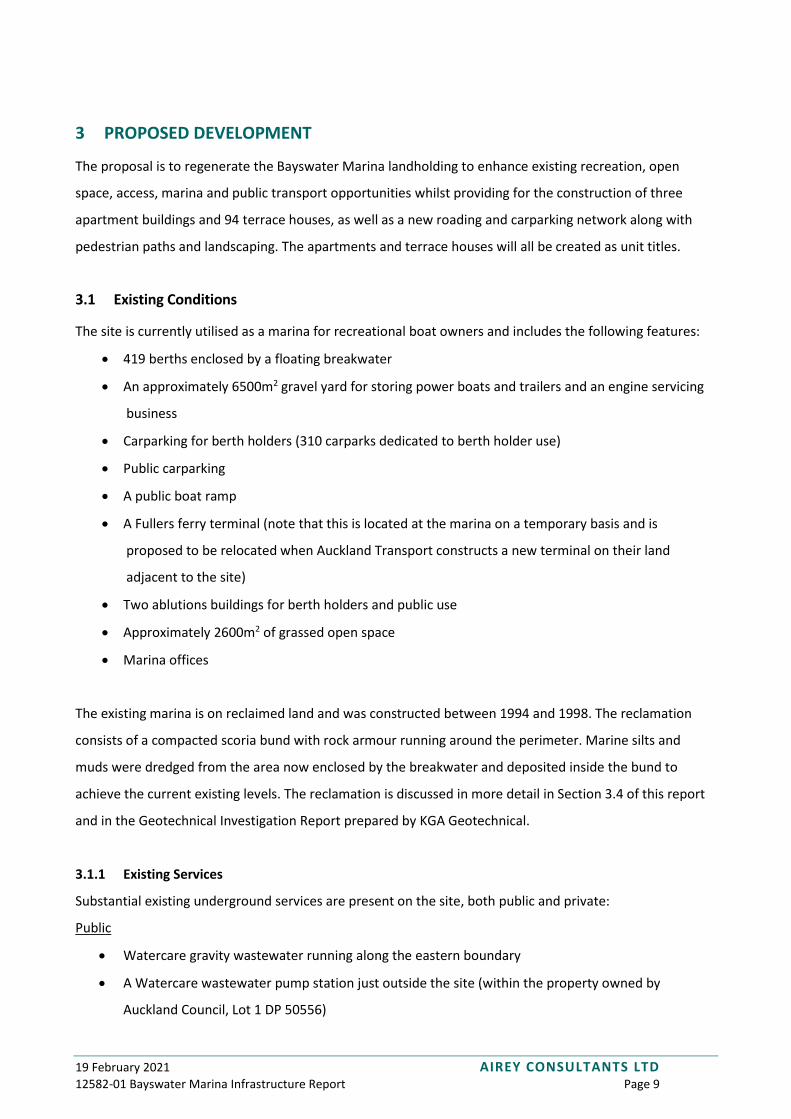
3.1 Existing Conditions
The site is currently utilised as a marina for recreational boat owners and includes the following features:
• 419 berths enclosed by a floating breakwater
• An approximately 6500m2 gravel yard for storing power boats and trailers and an engine servicing
business
• Carparking for berth holders (310 carparks dedicated to berth holder use)
• Public carparking
• A public boat ramp
• A Fullers ferry terminal (note that this is located at the marina on a temporary basis and is
proposed to be relocated when Auckland Transport constructs a new terminal on their land
adjacent to the site)
• Two ablutions buildings for berth holders and public use
• Approximately 2600m2 of grassed open space
• Marina offices
The existing marina is on reclaimed land and was constructed between 1994 and 1998. The reclamation
consists of a compacted scoria bund with rock armour running around the perimeter. Marine silts and
muds were dredged from the area now enclosed by the breakwater and deposited inside the bund to
achieve the current existing levels. The reclamation is discussed in more detail in Section 3.4 of this report
and in the Geotechnical Investigation Report prepared by KGA Geotechnical.
3.1.1 Existing Services
Substantial existing underground services are present on the site, both public and private:
Public
• Watercare gravity wastewater running along the eastern boundary
• A Watercare wastewater pump station just outside the site (within the property owned by
Auckland Council, Lot 1 DP 50556)

19 February 2021 AIREY CONSULTANTS LTD 12582-01 Bayswater Marina Infrastructure Report Page 10
• A Watercare watermain running along the eastern boundary, with a bulk meter located inside the
site
• Vector low and medium voltage power cabling and three transformers
• Chorus telecommunications cabling including a submarine cable connecting with Northcote
Private
• Stormwater pipes and swales collecting runoff from the roof and carparking areas
• Wastewater pipes servicing the existing ablutions buildings
• Water supply pipes servicing the existing ablutions buildings and the berths
• Low voltage electrical reticulation servicing the existing buildings and the berths
• Telecommunications (including security and fire alarm cabling) servicing the existing buildings and
the berths
The existing services supplying the marina berths will be maintained throughout the construction
works, the proposed staging and methodology is discussed in more detail in Section 3.2. Refer also to
the Existing Conditions and Demolition drawings included in Appendix A.
19 February 2021 AIREY CONSULTANTS LTD 12582-01 Bayswater Marina Infrastructure Report Page 11
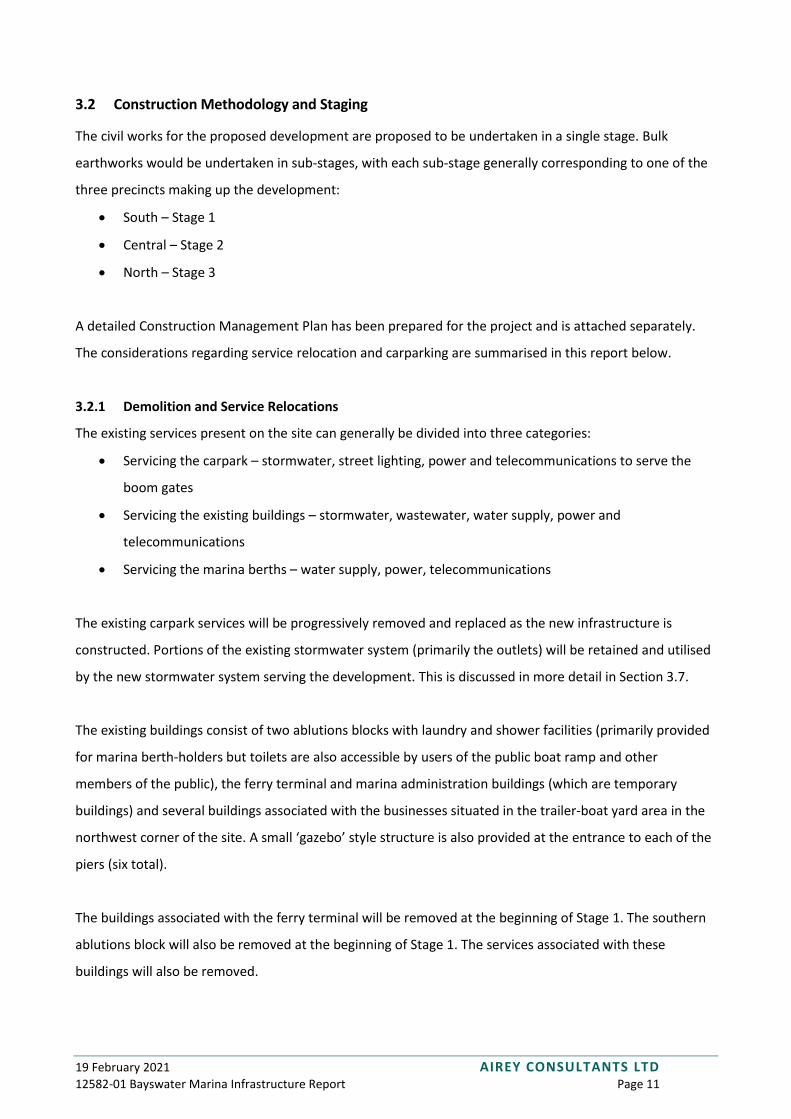
3.2 Construction Methodology and Staging
The civil works for the proposed development are proposed to be undertaken in a single stage. Bulk
earthworks would be undertaken in sub-stages, with each sub-stage generally corresponding to one of the
three precincts making up the development:
• South – Stage 1
• Central – Stage 2
• North – Stage 3
A detailed Construction Management Plan has been prepared for the project and is attached separately.
The considerations regarding service relocation and carparking are summarised in this report below.
3.2.1 Demolition and Service Relocations
The existing services present on the site can generally be divided into three categories:
• Servicing the carpark – stormwater, street lighting, power and telecommunications to serve the
boom gates
• Servicing the existing buildings – stormwater, wastewater, water supply, power and
telecommunications
• Servicing the marina berths – water supply, power, telecommunications
The existing carpark services will be progressively removed and replaced as the new infrastructure is
constructed. Portions of the existing stormwater system (primarily the outlets) will be retained and utilised
by the new stormwater system serving the development. This is discussed in more detail in Section 3.7.
The existing buildings consist of two ablutions blocks with laundry and shower facilities (primarily provided
for marina berth-holders but toilets are also accessible by users of the public boat ramp and other
members of the public), the ferry terminal and marina administration buildings (which are temporary
buildings) and several buildings associated with the businesses situated in the trailer-boat yard area in the
northwest corner of the site. A small ‘gazebo’ style structure is also provided at the entrance to each of the
piers (six total).
The buildings associated with the ferry terminal will be removed at the beginning of Stage 1. The southern
ablutions block will also be removed at the beginning of Stage 1. The services associated with these
buildings will also be removed.
19 February 2021 AIREY CONSULTANTS LTD 12582-01 Bayswater Marina Infrastructure Report Page 12
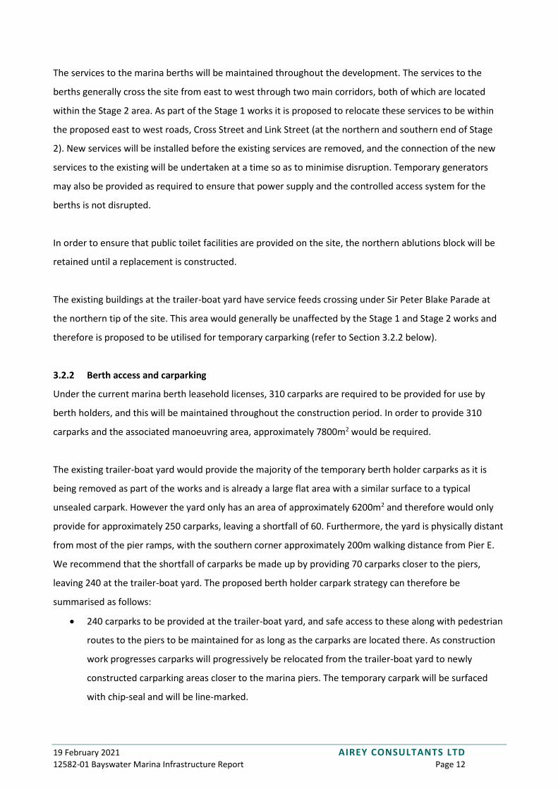
The services to the marina berths will be maintained throughout the development. The services to the
berths generally cross the site from east to west through two main corridors, both of which are located
within the Stage 2 area. As part of the Stage 1 works it is proposed to relocate these services to be within
the proposed east to west roads, Cross Street and Link Street (at the northern and southern end of Stage
2). New services will be installed before the existing services are removed, and the connection of the new
services to the existing will be undertaken at a time so as to minimise disruption. Temporary generators
may also be provided as required to ensure that power supply and the controlled access system for the
berths is not disrupted.
In order to ensure that public toilet facilities are provided on the site, the northern ablutions block will be
retained until a replacement is constructed.
The existing buildings at the trailer-boat yard have service feeds crossing under Sir Peter Blake Parade at
the northern tip of the site. This area would generally be unaffected by the Stage 1 and Stage 2 works and
therefore is proposed to be utilised for temporary carparking (refer to Section 3.2.2 below).
3.2.2 Berth access and carparking
Under the current marina berth leasehold licenses, 310 carparks are required to be provided for use by
berth holders, and this will be maintained throughout the construction period. In order to provide 310
carparks and the associated manoeuvring area, approximately 7800m2 would be required.
The existing trailer-boat yard would provide the majority of the temporary berth holder carparks as it is
being removed as part of the works and is already a large flat area with a similar surface to a typical
unsealed carpark. However the yard only has an area of approximately 6200m2 and therefore would only
provide for approximately 250 carparks, leaving a shortfall of 60. Furthermore, the yard is physically distant
from most of the pier ramps, with the southern corner approximately 200m walking distance from Pier E.
We recommend that the shortfall of carparks be made up by providing 70 carparks closer to the piers,
leaving 240 at the trailer-boat yard. The proposed berth holder carpark strategy can therefore be
summarised as follows:
• 240 carparks to be provided at the trailer-boat yard, and safe access to these along with pedestrian
routes to the piers to be maintained for as long as the carparks are located there. As construction
work progresses carparks will progressively be relocated from the trailer-boat yard to newly
constructed carparking areas closer to the marina piers. The temporary carpark will be surfaced
with chip-seal and will be line-marked.
19 February 2021 AIREY CONSULTANTS LTD 12582-01 Bayswater Marina Infrastructure Report Page 13
• 70 carparks to be located within the existing carpark area, and safe access to these along with
pedestrian routes to the piers to be maintained for as long as the carparks are located there. Once
construction in the southern precinct is complete these carparks will be relocated to the newly
construction carparks in the southern precinct. This area is already sealed but some additional line-
marking may be required.
19 February 2021 AIREY CONSULTANTS LTD 12582-01 Bayswater Marina Infrastructure Report Page 14
3.3 Flooding Considerations & Overland Flow Paths
This section should be read in conjunction with the Airey Consultants coastal inundation drawings (sheets
180-181) attached in Appendix A.
3.3.1 Flood plain and flood sensitive areas
The proposed development site is not subject to flooding as a result of stream or river flooding.
3.3.2 Coastal Inundation
Based on Auckland Council’s GeoMaps, the site is not subject to coastal inundation in the 1% AEP storm
event, but is subject to inundation under the 1% AEP storm event when 1m of sea level rise is accounted
for.

19 February 2021 AIREY CONSULTANTS LTD 12582-01 Bayswater Marina Infrastructure Report Page 15
Figure 2 - Coastal Inundation Extents (Auckland Council GeoMaps)
3.3.2.1 Finished Floor Levels
Auckland Council Technical Report TR 2016/017 – Coastal Inundation by Storm-tides and Waves in the
Auckland Region provides projections for extreme sea-level rise in the Waitemata Harbour. The projected
1% AEP sea level at the Bayswater Marina site is RL2.37 (based on Auckland Vertical Datum). The relevant
levels for determining minimum finished floor levels are as follows:
• 1% AEP sea level - RL2.37
• 1% AEP sea level plus 1m of sea level rise - RL3.37
The minimum habitable finished floor level on the site is therefore RL3.37. The proposed habitable floor
levels on the site range from RL3.30 to RL6.20, such that habitable floor levels in the proposed
19 February 2021 AIREY CONSULTANTS LTD 12582-01 Bayswater Marina Infrastructure Report Page 16
development are in accordance with E36.6.1.1 of the AUP (refer to Section 3.3.2.2) and are not a risk of
inundation as a result of sea level rise.
The proposed development will include basement carparking for each terraced house. Basements will be
‘half basements’ generally sunk 1.2m below surrounding ground levels. The proposed apartment buildings
will have full depth basements sunk 3.0m below surround ground levels. The lowest apartment basement
level is RL0.60 and the lowest terraced house basement level is RL3.40. All terrace house basements will be
above the sea level rise elevation of RL3.37. In order to prevent the site from from becoming inundated, it
is proposed to raise the perimeter of the site by approximately 1m (refer to the drawings attached in
Appendix A for detailed levels). This will result in the perimeter of the site being at a higher elevation than
RL3.37, and therefore preventing the majority of the site area from being inundated as a result of sea level
rise. Therefore, these areas are not subject to any impacts of the 1% AEP sea level rise plus 1m.
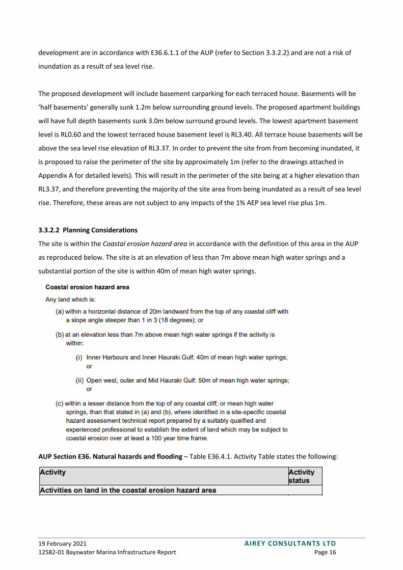
3.3.2.2 Planning Considerations
The site is within the Coastal erosion hazard area in accordance with the definition of this area in the AUP
as reproduced below. The site is at an elevation of less than 7m above mean high water springs and a
substantial portion of the site is within 40m of mean high water springs.
AUP Section E36. Natural hazards and flooding – Table E36.4.1. Activity Table states the following:
19 February 2021 AIREY CONSULTANTS LTD 12582-01 Bayswater Marina Infrastructure Report Page 17
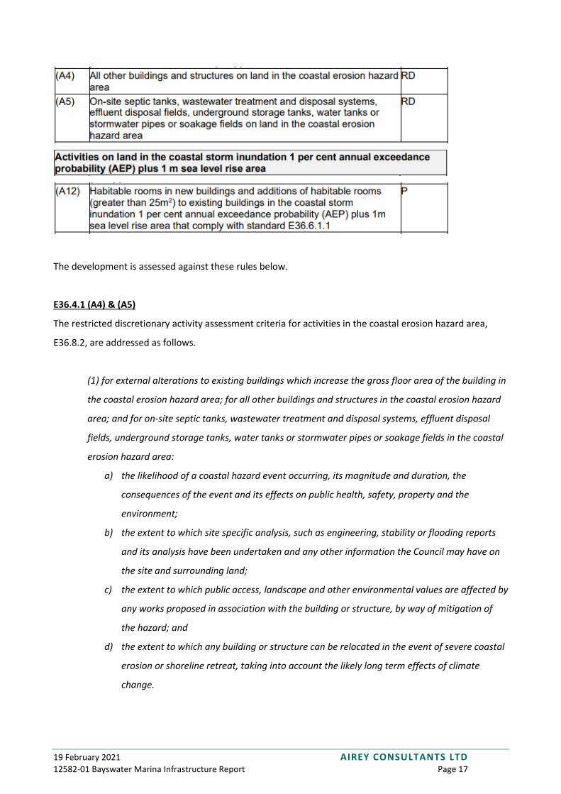
The development is assessed against these rules below.
E36.4.1 (A4) & (A5)
The restricted discretionary activity assessment criteria for activities in the coastal erosion hazard area,
E36.8.2, are addressed as follows.
(1) for external alterations to existing buildings which increase the gross floor area of the building in
the coastal erosion hazard area; for all other buildings and structures in the coastal erosion hazard
area; and for on-site septic tanks, wastewater treatment and disposal systems, effluent disposal
fields, underground storage tanks, water tanks or stormwater pipes or soakage fields in the coastal
erosion hazard area:
a) the likelihood of a coastal hazard event occurring, its magnitude and duration, the
consequences of the event and its effects on public health, safety, property and the
environment;
b) the extent to which site specific analysis, such as engineering, stability or flooding reports
and its analysis have been undertaken and any other information the Council may have on
the site and surrounding land;
c) the extent to which public access, landscape and other environmental values are affected by
any works proposed in association with the building or structure, by way of mitigation of
the hazard; and
d) the extent to which any building or structure can be relocated in the event of severe coastal
erosion or shoreline retreat, taking into account the likely long term effects of climate
change.

19 February 2021 AIREY CONSULTANTS LTD 12582-01 Bayswater Marina Infrastructure Report Page 18
The proposed activity being undertaken (residential development) is classified as a more vulnerable activity
under the AUP definitions. As the existing site is surrounding by a rock revetment wall designed in order to
prevent coastal erosion we consider that the site is not vulnerable to coastal erosion. The proposed
development will further raise the site higher above mean high water springs and will include a retaining
wall above the revetment wall which will further protect the site from coastal erosion. The extent of any
damage to people, property or the environment is considered to be minimal during a storm event up to
and including the 1% AEP storm (including allowance for climate change and sea level rise).
Public access is currently provided around the perimeter of the site by way of a footpath located behind the
rock revetment wall. Public access will be enhanced by the development as the proposed pathway located
on the new retaining wall will be substantially wider than the existing footpath; and will create a safe
surface for the public. The methodology for construction of the pathway has taken into account the fact
that public access must be maintained while the construction is being undertaken (refer to the
Construction Management Plan prepared by Airey Consultants), however it is recognised that some
temporary disruption to public access will be required in order to construct the pathway. We consider this
disruption to be acceptable in order to ultimately provide superior public access. We consider that the
impact of the proposed earthworks on landscape and other environmental values is negligible as long as
good practice erosion and sediment controls measures are maintained, this is discussed further in Section
3.5.
We note that the proposed buildings and structures are not designed to be able to be relocated. We
consider this to be acceptable owing to the substantial freeboard that has been provided above the 1% AEP
plus 1m sea level rise elevation, and to the fact that the site is protected against coastal erosion.
E36.4.1 (A12)
The standard referred to in Rule E36.4.1(A12) is as follows:
E36.6.1.1. Habitable rooms in new buildings and additions of habitable rooms (greater than 25m2) to
existing buildings in the coastal storm inundation 1 per cent annual exceedance probability (AEP) plus 1m
sea level rise area
(1) Finished floor levels of habitable rooms must be above the inundation level of the coastal storm
inundation 1 per cent annual exceedance probability (AEP) plus 1 metre sea level rise area.
19 February 2021 AIREY CONSULTANTS LTD 12582-01 Bayswater Marina Infrastructure Report Page 19
As discussed in Section 3.3.2.1 above, all proposed habitable floor levels in the development will be above
the 1% AEP coastal inundation plus 1m of sea level rise elevation, as shown on drawings 12582-01-180 –
181.
AUP Rule E36.9 requires that a hazard risk assessment be undertaken for any subdivision, use or
development proposed on land which may be subject to coastal storm inundation 1% AEP plus 1m sea level
rise. A hazard risk assessment has been undertaken in accordance with E36.9(2) and is provided below.
a) the type, frequency and scale of the natural hazard and whether adverse effects on the
development will be temporary or permanent;
The natural hazard pertaining to the site is coastal storm inundation 1 per cent annual exceedance
probability (AEP) plus 1m sea level rise which, as discussed in Section 3.3.2, relates to
approximately one-third of the site. The entire perimeter of the site is proposed to be raised above
the coastal storm inundation 1 per cent annual exceedance probability (AEP) plus 1m sea level rise
elevation, to eliminate the risk to buildings.
b) the type of activity being undertaken and its vulnerability to natural hazard events;
The 1m of sea level rise is projected to occur over the next 100 years and therefore the proposed
construction works (which are anticipated to be undertaken within several years of granting of the
consent) to facilitate the development are not at risk from sea level rise.
c) the consequences of a natural hazard event in relation to the proposed activity and the people likely
to be involved in that activity;
Some inundation of the site onto the South Park area could occur during a coastal storm inundation
1 per cent annual exceedance probability (AEP) plus 1m sea level rise event, however the extent of
inundation has been reduced to less than 8% of the site area, compared with the current extent of
inundation which is approximately 35% of the site area. The extent of inundation exceeds 10m
from all proposed habitable buildings, and therefore will not affect the safety of persons occupying
or travelling to and from the buildings.
d) the potential effects on public safety and other property;
Although the site is private property it does currently allow for public access due to the existing
ferry terminal and bus stop and around the perimeter of the site. The proposed development
includes enhanced public spaces and therefore it is anticipated that more members of the public

19 February 2021 AIREY CONSULTANTS LTD 12582-01 Bayswater Marina Infrastructure Report Page 20
will visit the site after the development is completed. The public areas of the development will
predominantly be located above the coastal storm inundation 1 per cent annual exceedance
probability (AEP) plus 1m sea level rise and therefore we do not consider there to be any adverse
risks in terms of public safety as a result of the development.
e) any exacerbation of an existing natural hazard risks or creation of a new natural hazard risks;
The proposed development does not exacerbate the existing coastal inundation hazard risk and
effectively reduces it by elevating the site above the hazard level.
f) whether any building, structure or activity located on land subject to natural hazards near the coast
can be relocated in the event of severe coastal erosion, coastal storm inundation or shoreline
retreat;
After the completion of the development there will be no buildings within the site on land subject
to coastal inundation and therefore no provision for the relocation of buildings is required. The
proposed pathway along the perimeter of the site that will provide access to the marina berths will
also be located above the coastal storm inundation 1 per cent annual exceedance probability (AEP)
plus 1m sea level rise elevation and therefore no provision for relocation of marina activities is
required.
g) the ability to use of non-structural solutions, such as planting or the retention or enhancement of
natural landform buffers to avoid, remedy or mitigate the hazard, rather than hard engineering
solutions or protection structures;
As the natural hazard pertaining to the site is coastal inundation as a result of projected sea level
rise, we consider that non-structural solutions are not appropriate for mitigating the hazard. The
hazard is fundamentally one of elevation, and the site needs to be raised above the elevation of
RL3.37 to fully avoid the hazard. It should also be noted that the entire site is reclaimed land
formed by way of a hard engineering solution. Therefore enhancement of the existing hard
engineering is considered to be the most appropriate way to avoid the coastal inundation risk.
h) the design and construction of buildings and structures to mitigate the effects of natural hazards;
The proposed gabion retaining wall to be constructed on the existing rock revetment wall has been
designed to be able to accommodate the projected coastal inundation including sea level rise. The
gabion baskets are porous and therefore water will be able to run through them. Geotextiles will be
provided to prevent water eroding the backfill soil behind the gabion baskets. Preliminary
structural details of the retaining wall are included in the drawing set in Appendix A.
19 February 2021 AIREY CONSULTANTS LTD 12582-01 Bayswater Marina Infrastructure Report Page 21
i) the effect of structures used to mitigate hazards on landscape values and public access;
The proposed retaining wall on the existing rock revetment wall will not be visible from the site or
any neighbouring properties. The provision of this retaining wall facilitates the creation of the
proposed public pathway, which will be elevated above the projected sea level rise elevation,
ensuring public access can be maintained for the life of the development.
j) site layout and management to avoid or mitigate the adverse effects of natural hazards, including
access and exit during a natural hazard event;
As has been discussed previously, the proposed development site layout has been designed in
order to mitigate the adverse effects of coastal inundation. In particular it should be noted that the
provision of the retaining wall and roads around the perimeter of the site being above RL3.37 will
ensure that coastal inundation does not disrupt access and exit to the site or to individual buildings.
k) the duration of consent and how this may limit the exposure for more or less vulnerable activities to
the effects of natural hazards including the effects of climate change;
The duration of the consent is largely irrelevant in relation to the coastal inundation hazard and the
proposed development. The design life of the development would be anticipated to be 100 years or
more and as such the fact that the habitable floor levels and the perimeter of the development are
located above the coastal storm inundation 1 per cent annual exceedance probability (AEP) plus 1m
sea level rise elevation is an important part of ensuring that the hazard is mitigated for the life of
the development.
l) any measures and/ or plans proposed to mitigate the natural hazard or the effects of the natural
hazard.
The proposed raising of the site is the primary measure by which the coastal inundation hazard is
mitigated. No specific plans or otherwise are proposed.
3.3.3 Overland flow paths
The site undulates, and generally falls from the centre of the site in a westerly or easterly direction towards
the ocean. Several small overland flow paths are shown on the Auckland Council GeoMaps, as shown on
Figure 3. These small overland flow paths are all generated within the subject site and are shown to flow
into the Waitemata Harbour. Overland flows within the development have been designed to be directed

19 February 2021 AIREY CONSULTANTS LTD 12582-01 Bayswater Marina Infrastructure Report Page 22
along the proposed parking and roading areas and into the harbour. There is no potential for any overland
flow paths to cause flooding on any neighbouring property.
Figure 3 - Existing Overland Flow Paths

19 February 2021 AIREY CONSULTANTS LTD 12582-01 Bayswater Marina Infrastructure Report Page 23
3.4 Geotechnical Engineering
A geotechnical investigation has been undertaken by KGA Geotechnical and reference should be made to
their report.
3.4.1 Differential Settlement
Based on the low quality of the material within the reclamation and the varied extent of both cut and fill
across the site, differential will occur. Differential settlement is the process whereby the soil underlying
constructed structures or pavements is compressed at different rates. This results in visible level
differences in the finished surface can cause failures to the structures or pavements and are also
undesirable from an aesthetic perspective. Differential settlement can also result in damage to services if
they are not designed to accommodate differential movement. In order to manage differential settlement
the following measures are proposed.
• Buildings will be supported on piles/ground improvements founded in bedrock so that no
settlement of buildings will occur.
• Settlement slabs are proposed to be provided at the interface between buildings and pavements.
The settlement slabs will be structurally connected to the structural slab at one end but will be
isolated from the adjoining pavement. This slab will then pivot at one end to transition the level
difference created by the differential settlement.
• The concrete pavements will be provided with a joint layout and joint system designed specifically
to mitigate differential settlement. The design of this will be undertaken at the detailed design
stage.
• The existing lime stabilised fill layers will be reused and recompacted to provide stronger platforms
for the construction of the pavements and services across these platforms.
• Any piped or ducted services that are suspended beneath structural slabs will be provided with
flexible joints at the point where they become suspended. These joints will accommodate the
movement that may arise due to differential settlement between the surrounding ground and the
piled structure.
The Geotechnical Investigation Report prepared by KGA Geotechnical contains further information on
earthworks and site formation recommendations.

19 February 2021 AIREY CONSULTANTS LTD 12582-01 Bayswater Marina Infrastructure Report Page 24
3.5 Earthworks
This section should be read in conjunction with the Airey Consultants earthworks drawings (sheets 200 –
236) attached in Appendix A.
3.5.1 Existing Site
The surface of the existing site is predominantly asphalt and is generally flat. The different site coverages
are as follows:
• Asphalt pavement and concrete footpaths - 19,840m2
• Unsealed trailer-boat yard - 6,500m2
• Grassed areas - 6,200m2
• Buildings - 860m2
The site is fully reclaimed harbour silts/muds constructed from dredging of the adjacent marina. The upper
1.5 - 2.0m depth of the material was lime stabilised to provide a higher strength material on the upper
surface to support the existing carparks, buildings and services. A rock revetment wall around the
perimeter of the site provides edge support to the reclamation and protection against wave/tidal action.
Our assessment is that the extent of ground settlement since the reclamation is minimal, however
reference should be made to the KGA Geotechnical report for more discussion of this.
3.5.2 Proposed Earthworks
Cut to fill earthworks across the site are proposed in order to:
• raise the site above the 1% AEP sea level plus 1m of sea level rise elevation of RL3.37
• form building platforms
• create road and pavement subgrades
The earthworks have been designed to be undertaken as a cut to fill operation and will be undertaken in
sub-stages, as described in section 3.2. Silt fences and sediment diversion drains will be provided around
the harbour-side perimeter of each stage, and sediment retention ponds will be utilised to provide
sediment control.
The estimated earthwork quantities are shown in Table 1.
19 February 2021 AIREY CONSULTANTS LTD 12582-01 Bayswater Marina Infrastructure Report Page 25
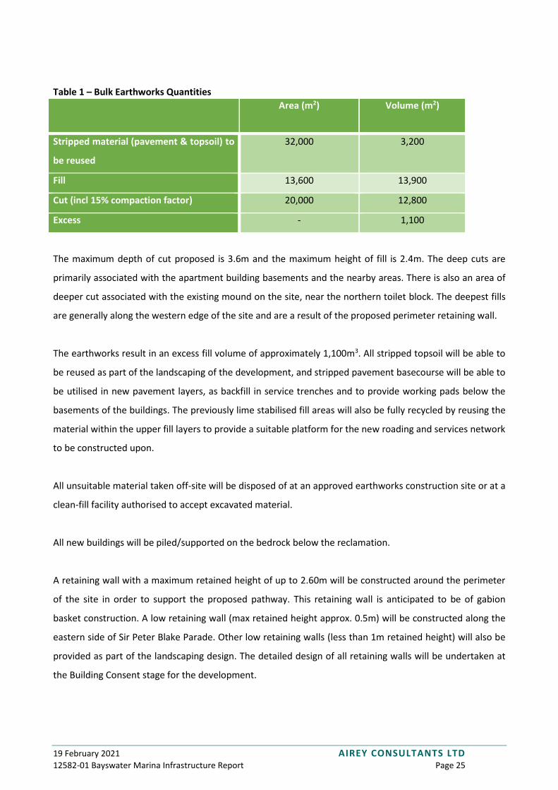
Table 1 – Bulk Earthworks Quantities
Area (m2) Volume (m2)
Stripped material (pavement & topsoil) to
be reused
32,000 3,200
Fill 13,600 13,900
Cut (incl 15% compaction factor) 20,000 12,800
Excess - 1,100
The maximum depth of cut proposed is 3.6m and the maximum height of fill is 2.4m. The deep cuts are
primarily associated with the apartment building basements and the nearby areas. There is also an area of
deeper cut associated with the existing mound on the site, near the northern toilet block. The deepest fills
are generally along the western edge of the site and are a result of the proposed perimeter retaining wall.
The earthworks result in an excess fill volume of approximately 1,100m3. All stripped topsoil will be able to
be reused as part of the landscaping of the development, and stripped pavement basecourse will be able to
be utilised in new pavement layers, as backfill in service trenches and to provide working pads below the
basements of the buildings. The previously lime stabilised fill areas will also be fully recycled by reusing the
material within the upper fill layers to provide a suitable platform for the new roading and services network
to be constructed upon.
All unsuitable material taken off-site will be disposed of at an approved earthworks construction site or at a
clean-fill facility authorised to accept excavated material.
All new buildings will be piled/supported on the bedrock below the reclamation.
A retaining wall with a maximum retained height of up to 2.60m will be constructed around the perimeter
of the site in order to support the proposed pathway. This retaining wall is anticipated to be of gabion
basket construction. A low retaining wall (max retained height approx. 0.5m) will be constructed along the
eastern side of Sir Peter Blake Parade. Other low retaining walls (less than 1m retained height) will also be
provided as part of the landscaping design. The detailed design of all retaining walls will be undertaken at
the Building Consent stage for the development.
19 February 2021 AIREY CONSULTANTS LTD 12582-01 Bayswater Marina Infrastructure Report Page 26
3.5.3 Auckland Unitary Plan (AUP)
AUP provisions relating to the proposed earthworks include:
• E11 – Land Disturbance – Regional
• E12 – Land Disturbance – District
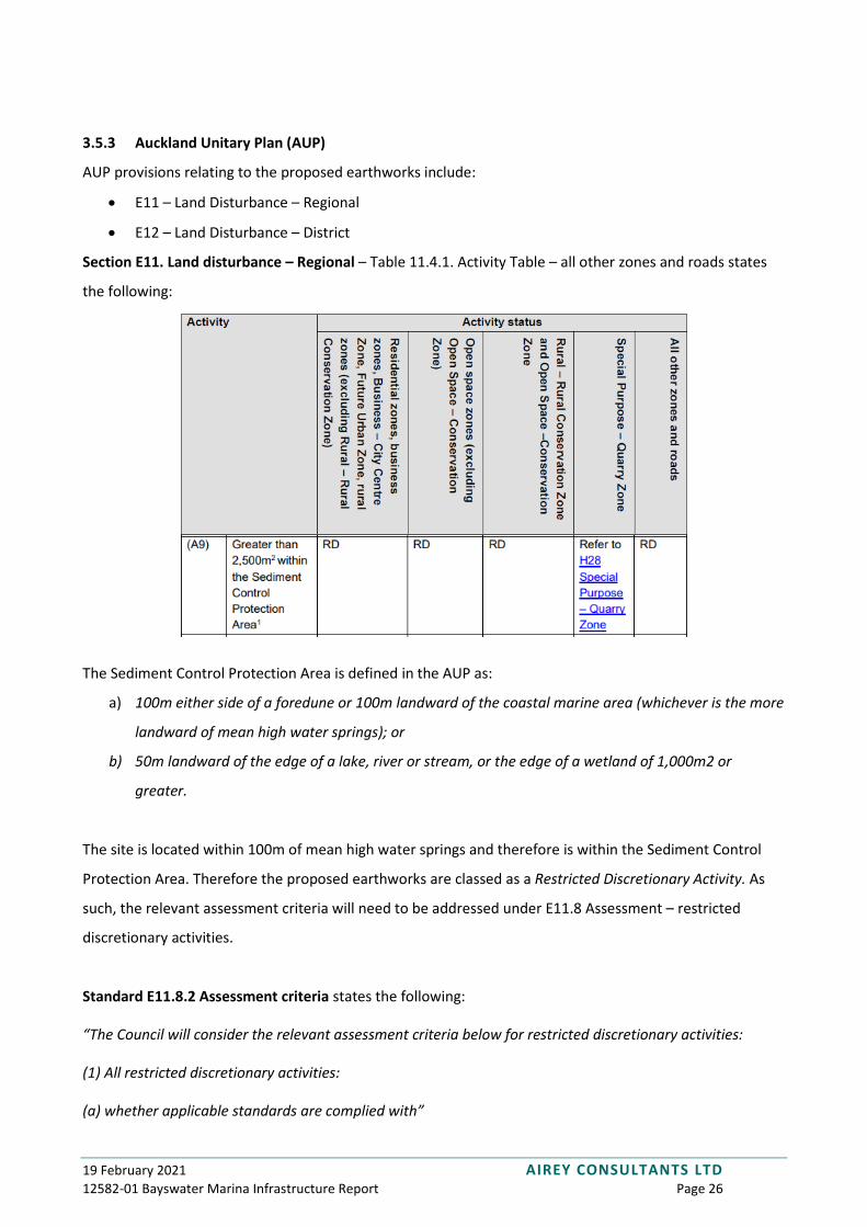
Section E11. Land disturbance – Regional – Table 11.4.1. Activity Table – all other zones and roads states
the following:
The Sediment Control Protection Area is defined in the AUP as:
a) 100m either side of a foredune or 100m landward of the coastal marine area (whichever is the more
landward of mean high water springs); or
b) 50m landward of the edge of a lake, river or stream, or the edge of a wetland of 1,000m2 or
greater.
The site is located within 100m of mean high water springs and therefore is within the Sediment Control
Protection Area. Therefore the proposed earthworks are classed as a Restricted Discretionary Activity. As
such, the relevant assessment criteria will need to be addressed under E11.8 Assessment – restricted
discretionary activities.
Standard E11.8.2 Assessment criteria states the following:
“The Council will consider the relevant assessment criteria below for restricted discretionary activities:
(1) All restricted discretionary activities:
(a) whether applicable standards are complied with”

19 February 2021 AIREY CONSULTANTS LTD 12582-01 Bayswater Marina Infrastructure Report Page 27
We consider all applicable standards have been complied with as assessed above and that all proposed
works comply with GD05.
“(b) the proximity of the earthworks to any water body and the extent to which erosion and sediment
controls and the proposed construction methodology will adequately avoid or minimise adverse effects on:
(i) water quality including of the coastal marine area;
(ii) ecological health including of the coastal marine area;
(iii) riparian margins;
(iv) the mauri of water; and
(v) the quality of taiāpure or mahinga mātaitai.”
The Waitemata Harbour Coastal Marine Area (CMA) is the receiving environment for the site. The
catchment area of Shoal Bay is approximately 457ha (as discussed above) and the site has an area of 3.34ha
which is approximately 0.7% of the catchment. The proposed erosion and sediment controls are designed
to prevent sediment laden runoff from being discharged from the site and therefore to minimise effects on
the downstream environment. We consider that no adverse impact on the CMA is anticipated.
“(c) the extent to which the earthworks minimises soil compaction, other than where it benefits
geotechnical or structural performance”
Substantial soil compaction will be required over most of the site in order to construct the proposed
pavements. This compaction is required to ensure structural performance of the pavements. The building
foundations will be piled into bedrock and therefore high levels of soil compaction are unlikely to be
required in the areas where buildings are to be constructed. It should be noted that the site soils are of
poor quality and that several hundred millimetres of settlement has occurred since the marina was
constructed.
“(d) the proximity of the earthworks to areas of significant ecological value and the extent the design,
location and execution of the works provide for the maintenance and protection of these areas”
The proposed earthworks are not in proximity to any areas of significant ecological value.
“(e) whether monitoring the volume and concentration of sediment that may be discharged by the activity is
appropriate within the scale of the proposed land disturbance”
19 February 2021 AIREY CONSULTANTS LTD 12582-01 Bayswater Marina Infrastructure Report Page 28
Monitoring by Council is anticipated for this site in addition to that provided by the contractors and
Engineers. Monitoring will be undertaken by the bulk earthworks contractor and the controls will be
checked before and after periods of heavy rain. Controls will also be checked by the Engineer at least once
a fortnight. We do not consider that any specific monitoring programme is warranted for this site other
than regular weekly or fortnightly visits by Council’s Erosion and Sediment Control Team.
“(f) whether the extent or impacts of adverse effects from the land disturbance can be mitigated by
managing the duration, season or staging of such works”
The bulk earthworks will be undertaken in three primary stages as documented on the erosion and
sediment control plans. Each stage will be progressively stabilised with metal or topsoil and hydroseeding.
We consider that staging the bulk earthworks will help to minimise the adverse effects associated with the
bulk earthworks.
“(g) the extent to which appropriate methods are used to prevent the spread of total control pest plants or
unwanted organisms (as listed under the Biosecurity Act 1993), such as kauri dieback disease.”
No pest plants or unwanted organisms have been identified on the site.
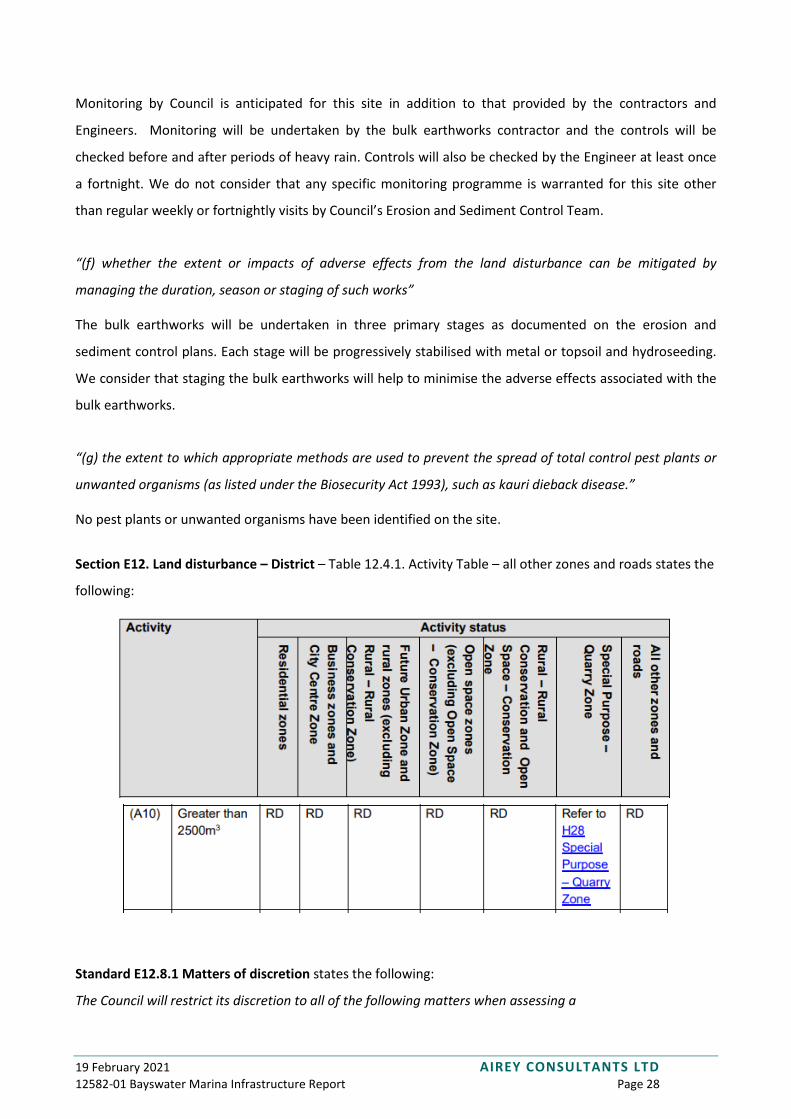
Section E12. Land disturbance – District – Table 12.4.1. Activity Table – all other zones and roads states the
following:
Standard E12.8.1 Matters of discretion states the following:
The Council will restrict its discretion to all of the following matters when assessing a

19 February 2021 AIREY CONSULTANTS LTD 12582-01 Bayswater Marina Infrastructure Report Page 29
restricted discretionary resource consent application:
(1) all restricted discretionary activities:
(a) compliance with the standards;
The erosion and sediment control design has been prepared in accordance with GD05.
(b) effects of noise, vibration, odour, dust, lighting and traffic on the surrounding
environment;
A Noise and Vibration Assessment of the proposed development has been undertaken by Marshall Day and
a Traffic Impact Assessment has been undertaken by Stantec. Dust control in accordance with GD05 will be
provided for the duration of the earthworks. Dust control will primarily be provided by watercart. No
odours are anticipated to be generated by the earthworks.
(c) effects on the stability and safety of surrounding land, buildings and structures;
It should be noted that the site has no surrounding land to the north, south and west. The neighbouring
land to the east is occupied by a carpark and a large shed-type structure. The shed is located approximately
6m from the property boundary. Bulk earthworks and retaining wall construction will be undertaken
immediately adjacent to the property boundary. As the adjoining land is a much older reclamation than the
subject site (approximately 80 years old), we do not anticipate any further settlement in this area. We
consider that there will be no adverse effects on the stability and safety of the surrounding land, buildings
and structures.
(d) effects on overland flow paths and flooding;
The site is not subject to flooding and the only overland flow paths running through it are minor and arise
within the site. There we do not consider that there will be any effects on overland flow paths or flooding
that will impact other properties.
(e) protocol for the accidental discovery of kōiwi, archaeology and artefacts of Māori
origin;
As the site was reclaimed relatively recently (1990s), we consider that the likelihood of accidental discovery
is very low. If any kōiwi, archaeology and artefacts of Māori origin are discovered works will be halted and
the relevant Mana Whenua authority and Heritage New Zealand will be notified.
(f) the treatment of stockpiled materials on the site including requirements to remove material if it is not to
be reused on the site;
19 February 2021 AIREY CONSULTANTS LTD 12582-01 Bayswater Marina Infrastructure Report Page 30
Stockpiles will be located in appropriate locations set back from the coast. Stockpiles will be stabilised if
they are not being actively used, and will be provided with specific erosion and sediment control measures
if they are being actively used.
(g) staging of works and progressive stabilisation;
The bulk earthworks will be undertaken in three primary stages as documented on the erosion and
sediment control plans. Each stage will be progressively stabilised with metal or topsoil and hydroseeding.
We consider that staging the bulk earthworks will help to minimise the adverse effects associated with the
bulk earthworks.
(h) information and monitoring requirements;
Monitoring by Council is anticipated for this site in addition to that provided by the contractors and
Engineers. Monitoring will be undertaken by the bulk earthworks contractor and the controls will be
checked before and after periods of heavy rain. Controls will also be checked by the Engineer at least once
a fortnight. We do not consider that any specific monitoring programme is warranted for this site other
than regular weekly or fortnightly visits by Council’s Erosion and Sediment Control Team.
(i) timing and duration of works;
The bulk earthworks works are anticipated to be undertaken within a single earthworks construction
season (from October to May).
(j) term of consent;
A five-year consent is requested to match the subdivision consent approval period.
(k) potential effects on significant ecological and indigenous biodiversity values;
The proposed earthworks are not in proximity to any areas of significant ecological value. The site primarily
operates as a carpark and has very low ecological value. As many of the existing Pohutukawa trees as
practicable are proposed to be retained, in particular the row of six trees south of the existing boat ramp
which are to be retained in place. Other existing Pohutukawas will be replanted within the development.
(l) risk that may occur as a result of natural hazards;
Portions of the site are currently located within the 1% AEP plus 1m of sea level rise hazard area and
therefore there is a very low risk of the earth-worked area being subject to inundation. As the proposed
19 February 2021 AIREY CONSULTANTS LTD 12582-01 Bayswater Marina Infrastructure Report Page 31
earthworks are being undertaken in order to raise the site above the inundation level we consider that this
risk is acceptable during the earthworks period.
(m) protection of or provision of network utilities and road networks.
The existing network utilities within or near the site include wastewater reticulation, water supply
electricity reticulation and telecommunications reticulation. The existing public wastewater and water
supply are outside the site boundary and will be unaffected by the proposed works. Electrical and
telecommunications reticulation within the site will either be relocated prior to the bulk earthworks or will
be protected during the works.
(n) potential effects on the natural character and values of the coastal environment, lakes, rivers and their
margins, where works encroach into riparian or coastal yards; and
As the extents of the existing reclamation are not being altered we consider that there is no adverse effect
on the natural character and values of the coastal environment, noting that the site is reclaimed land and is
not natural.
(o) positive effects enabled through the land disturbance.
The development includes an approximately 3.5m wide (proposed width varies, refer to the Boffa Miskell
landscape drawings for details) pathway that will replace the existing 1.5m wide concrete footpath that
runs around the coastal perimeter of the site. The pathway will be open to the public and will make the
coastal frontage much more accessible to members of the public. We consider this to be a highly positive
effect that is enabled through the proposed land disturbance.
3.5.4 Erosion and Sediment Control
Full silt and sediment control measures will be provided throughout the development of the project in
accordance with the requirements of Auckland Council GD05. Silt control measures will be installed to
prevent sediment discharge to the Waitemata Harbour. The site will be split into the three sub-stages 1 - 3
catchment areas.
In each catchment the basement excavations for one row of terrace houses will be undertaken and the
excavation will then be utilised as a sediment retention pond as shown on drawing 12582-01-230. Silt
fences will also be provided around the entire perimeter of the site to capture any small, localised runoff
from areas that cannot be directed towards the sediment retention ponds. The site will be filled from the
19 February 2021 AIREY CONSULTANTS LTD 12582-01 Bayswater Marina Infrastructure Report Page 32
perimeter first moving gradually inwards as layers are built up, to shape the site towards the sediment
retention ponds. Removal of the sediment ponds and final shaping of the townhouse basement excavations
will be undertaken following the stabilisation of each earthworks catchment.
The deep excavations for the apartment building basements will be at lower elevations than the
surrounding areas and therefore no runoff will occur from these areas. Due to the depth of these
excavations (below mean high water springs) groundwater influx will occur and therefore dewatering will
be provided. The dewatering pumps will pump the water to the sediment retention pond within the
catchment for that stage which will ensure that sediment control is provided for this water.
The bulk earthworks within the development are proposed to be undertaken during the earthworks
construction season from October to May.
All earth-worked areas will be progressively stabilised upon completion of earthworks in within each stage.
Stabilisation will be provided by basecourse metalling of proposed pavement and building areas; and laying
topsoil, grass seed and mulch for the landscaped areas.
19 February 2021 AIREY CONSULTANTS LTD 12582-01 Bayswater Marina Infrastructure Report Page 33
3.6 Roading & Access
This section should be read in conjunction with the Airey Consultants roading and access drawings (sheets
300 – 307) attached in Appendix A.
3.6.1 Existing Site
The site is accessed from the western end of Bayswater Ave via Sir Peter Blake Parade. The public road
reserve terminates approximately 30m inside the site boundary, however there is no visual demarcation
and the public road extent seamlessly transitions into the marina access road.
Sir Peter Blake Parade is a crowned road approximately 8m wide with a concrete footpath located on the
western side. A footpath follows the rock revetment wall around the perimeter of the site, with another in
a north-south direction along the middle of the site. The footpaths converge near the ferry terminal at the
southern tip of the site.
The existing site primarily consists of sealed carparking and is generally flat but undulates due to areas of
previous differential settlement. The existing pavement generally consists of 200mm thick GAP65 subbase
overlain with 100mm AP40 basecourse with either asphaltic concrete or chip seal wearing course (as shown
on the as-built drawings from the marina construction).
3.6.2 Proposed Roading & Access
Stantec have undertaken a Traffic Impact Assessment for the proposed development which will form part
of this resource consent application.
The proposed development includes the construction of new private roads to provide access to the
buildings and carparks while maintaining access to the marina berths. All roads will be private access roads
and are not proposed to be vested.
The proposed pavement types are as follows:
• Asphalt – Sir Peter Blake Parade, Link Street, Cross Street, South Street
• Coloured concrete or similar – North Lane
• Concrete with black oxide – access and manoeuvring areas within the North, Central and South
Precincts
• Concrete – footpaths and other pedestrian areas

19 February 2021 AIREY CONSULTANTS LTD 12582-01 Bayswater Marina Infrastructure Report Page 34
• Concrete with planted reinforced soil infill – parking bays.
Reference should be made to the landscape architecture drawings prepared by Boffa Miskell for more
details of the surface finishes and road widths.

19 February 2021 AIREY CONSULTANTS LTD 12582-01 Bayswater Marina Infrastructure Report Page 35
3.7 Stormwater
This section should be read in conjunction with the Airey Consultants stormwater drawings (sheets 400 –
420) attached in Appendix A.
3.7.1 Existing Stormwater Reticulation
There is no public stormwater infrastructure present on the site. There is private stormwater infrastructure
draining the existing carpark and buildings. The private stormwater network consists of cesspits, manholes,
swales and pipes which discharge to the harbour through six outlets through the rock revetment bund. The
outlets are all located below Mean High Water Springs (MHWS). The existing stormwater pipes are
generally 225 to 375mm diameter. No stormwater quality or quantity treatment is provided on the site,
except for some minimal treatment from the existing swales.
The bulk of the existing stormwater reticulation (except for the outlets) will be decommissioned and
replaced during the development, with the exception of the pipeline located adjacent to the eastern
boundary of the site, which is within the neighbouring Auckland Council land.
3.7.2 Proposed Stormwater Reticulation
Stormwater runoff generated from the development is proposed to be collected in a private stormwater
system and discharged to the Waitemata Harbour through seven outlets. All except one of these
stormwater outlets are either existing outlets or upgrades of existing outlets, therefore the increase in the
number of outfalls to the harbour is limited to one new outlet. It should be noted that two of the new
outlets are located below MHWS.
The drainage network will collect runoff from buildings roofs, paved surfaces and any overland flow from
pervious surfaces. The drainage network will generally be constructed within the central courtyards of each
precinct and will direct stormwater to the perimeter of the site to discharge to the harbour. The
stormwater drainage reticulation has been designed to accommodate runoff from rainfall events up to and
including the 10% AEP storm with allowance for climate change, in accordance with Auckland Council’s
Stormwater Code of Practice. The detailed design of the stormwater reticulation will be undertaken at the
Building Consent stage in accordance with the requirements of the NZ Building Code.
3.7.3 Auckland Unitary Plan (AUP)
AUP stormwater provisions relating to the site include:
19 February 2021 AIREY CONSULTANTS LTD 12582-01 Bayswater Marina Infrastructure Report Page 36
• F2 - General Coastal Marine Zone
o Policy F2.11.3 requires any discharge of stormwater into the coastal marine area to adopt
the best practicable option to prevent or minimise adverse effects on the environment.
This policy also aims to reduce the amount of litter entering receiving waters.
• E8 – Stormwater – Discharge and Diversion
o Stormwater discharges to the Coastal Marine area are covered under E8.4.1(A3)
o E8.6 General Standards are addressed as follows:
1) The design of the proposed stormwater management device(s) must be consistent with any relevant
precinct plan that addresses or addressed stormwater matters.
The site is located within the Bayswater Marina Precinct but this precinct does not include any
provisions with respect to stormwater matters.
2) The diversion and discharge must not cause or increase scouring or erosion at the point of discharge
or downstream.
The stormwater outlets will be provided with suitable erosion control measures to ensure that
there will be no increase in scouring or erosion at the point of discharge. We note that there will be
no erosion or scour downstream as the receiving environment is the Waitemata Harbour. The
detailed design of the stormwater outlets will be undertaken at the Building Consent Stage.
3) The diversion and discharge must not result in or increase the following:
a. flooding of other properties in rainfall events up to the 10 per cent annual exceedance
probability (AEP); or
b. inundation of buildings on other properties in events up to the 1 per cent annual
exceedance probability (AEP).
All stormwater runoff from rainfall events up to and including the 10% AEP storm will be captured
in the proposed stormwater pipe network and discharged to the Waitemata through the
stormwater outlets described above. The development will not result in flooding of other
properties in rainfall events up to and including the 10% AEP storm.
Overland flow paths will be provided in order to ensure that no inundation of buildings occurs in
events up and including the 1% AEP storm. The overland flow paths will direct runoff over the
perimeter retaining walls and into the Waitemata Harbour. There are two locations (Link St & Cross
St) where overland flow paths to the harbour are not possible due to the design levels of the
development. At these locations stormwater inlets will be provided, these will direct runoff to large
stormwater pipelines which will discharge the runoff to the Waitemata Harbour. These stormwater
19 February 2021 AIREY CONSULTANTS LTD 12582-01 Bayswater Marina Infrastructure Report Page 37
inlets and pipelines will be designed to accommodate the 1% AEP storm with allowance for
blockage in accordance with Auckland Council’s Stormwater Code of Practice.
4) The diversion and discharge must not cause or increase nuisance or damage to other properties.
There are no downstream properties between the site and the receiving environment. The
proposed stormwater discharge will not cause or increase nuisance or damage to other properties.
5) The diversion and discharge of stormwater runoff must not give rise to the following in any surface
water or coastal water:
a. the production of conspicuous oil or grease films, scums or foams, or floatable or suspended
materials;
b. any conspicuous change in the colour or visual clarity;
c. any emission of objectionable odour;
d. the rendering of fresh water unsuitable for consumption by farm animals; or
e. any significant adverse effects on aquatic life.
As discussed in Stormwater Management – Quality, stormwater treatment raingardens and
proprietary filtration devices will be provided to treat runoff from all impervious areas. Provision of
these treatment devices will ensure that there is no:
- conspicuous oil/grease/scum/foams/floatable or suspended material in the coastal
water
- conspicuous change in colour or visual clarity of the coastal water
- emissions of objectionable odour
- adverse effect on aquatic life.
Currently the site contains a large proportion of impervious carparking area with minimal
stormwater quality treatment provided. We consider that the proposal will improve the water
quality of the stormwater discharge from the site.
6) Where the diversion and discharge is to ground soakage, groundwater recharge or peat soil areas
any existing requirements for ground soakage, including devices to manage discharges or soakage,
must be complied with
The proposed discharge is not to ground soakage.
In order to comply with the intent, policy and rules of the AUP, the stormwater management for the
development is proposed to achieve the following:
19 February 2021 AIREY CONSULTANTS LTD 12582-01 Bayswater Marina Infrastructure Report Page 38
• No increase in stormwater flows and volumes for rainfall events up to and including the 10% AEP
storm
• Provide stormwater quality treatment using a Best Practicable Option (BPO) approach
• Minimise the amount of litter entering the receiving environment
• Avoid erosion, land instability, scour and flooding
Stormwater Management – Quantity
The proposed development increases the pervious area on the site by approximately 1,300m2, as shown
below.
Pre-development:
• Pervious area - 6,200m2
• Impervious area - 27,200m2
Post-development:
• Pervious area – 7,530m2
• Impervious area - 7,620m2 roof
18,250m2 paving
25,870m2 total
As a consequence of the increase in pervious area on the site, the flow rate and volume of stormwater
runoff will decrease as a result of the development. Both peak flow rate and volume will reduce by
approximately 1% as shown in Table 2.

19 February 2021 AIREY CONSULTANTS LTD 12582-01 Bayswater Marina Infrastructure Report Page 39
Table 2 - Runoff flow rates and volumes
10% AEP peak
flowrate (m3/s)
10% AEP 24-hr
volume (m3)
1% AEP peak
flowrate (m3/s)
1% AEP 24-hr
volume (m3)
Pre-development 0.800 4592 1.285 7428
Post-development 0.789 4518 1.275 7342
Percentage
decrease
1% 2% 1% 1%
As the runoff volume and peak flow rate is actually decreased as a result of the development, no
stormwater quantity treatment is proposed. The site discharges directly into the Waitemata Harbour and
the effect of any increase or decrease in the quantity of flow would provide no ecological impact.
Stormwater Management – Quality
Currently the site does not formally provide any stormwater quality treatment. A grassed swale does run
around the western edge of the site but provides minimal stormwater treatment and is primarily for
conveyance.
The proposed development includes the redevelopment of an existing high contaminant generating
carpark, and therefore the controlled activity standards under AUP rule E9.6.2.1 must be complied with.
E9.6.2.1. Development of a new or redevelopment of an existing high contaminant generating car park
greater than 5,000m2
(1) The development of a new or redevelopment of an existing high contaminant generating car park
must not be located in an industrial and trade activity area.
The development is not located in an industrial and trade activity area.
(2) Stormwater runoff from an impervious area used for a high contaminant generating car park must
be treated by stormwater management device(s).
Stormwater management devices will be provided to treat all runoff from impervious areas.
(3) Where a high contaminant generating car park is more than 50 per cent of the total impervious
area of a site, stormwater runoff from the total impervious area on the site must be treated by
stormwater management device(s).

19 February 2021 AIREY CONSULTANTS LTD 12582-01 Bayswater Marina Infrastructure Report Page 40
The proposed carpark area (including access and manoeuvring areas) makes up 63% of the total
impervious area. As such AUP rule E9.6.2.1 requires that stormwater treatment devices compliant
with Auckland Council GD01 are provided for all impervious areas, including roofs. This will be
provided by way of raingardens and bioretention tree pits located along the road edges and in the
central courtyards. A grass swale is also proposed running along the western edge of the site which
will provide some additional stormwater quality treatment. In order to provide treatment of the
roof runoff, it is proposed to provide proprietary treatment devices (hydrodynamic separators or
filtration devices) located on the pipe networks. Seven proprietary devices will be required as
shown on the stormwater plans. The specific proprietary treatment devices will be specified and
designed at the building consent design stage and will be capable of providing treatment in
accordance with GD01. Stormwater360 StormFilters or similar devices are anticipated.
(4) The stormwater management device(s) must meet the following:
a. the device or system must be sized and designed in accordance with ‘Guidance Document
2017/001 Stormwater Management Devices in the Auckland Region (GD01)’; or
b. where alternative devices are proposed, the device must demonstrate it is designed to
achieve an equivalent level of contaminant or sediment removal performance to that of
‘Guidance Document 2017/001 Stormwater Management Devices in the Auckland
Region(GD01)’.
All stormwater treatment devices will be in accordance with GD-1.
The proposed stormwater treatment devices and catchments are summarised in Table 3 below.
Table 3 - Stormwater Treatment Devices/Catchments
Catchment
area (m2)
Min. treatment
area (m2)
Proposed treatment
area (m2)
Bioretention 14,280 288 292
Proprietary devices 11,590 - -
Raingardens/bioretention tree pits are considered to be the best practicable option for providing
stormwater quality treatment of the paved areas within the development for the following reasons:
• Space constraints – due to the high density nature of the development, there is not considered to
be suitable space for providing a pond or wetland. These treatment devices would need to be
located in the northern or southeastern open spaces and would result in the majority of at least

19 February 2021 AIREY CONSULTANTS LTD 12582-01 Bayswater Marina Infrastructure Report Page 41
one of these areas being essentially unusable. In urban areas ponds or wetlands can be desirable
due to the positive impacts of providing a body of water in a community area, but as the
development is surrounded by water on three sides this is considered to be unnecessary.
• Integrated into landscape – the raingarden and treepit locations have been coordinated with the
landscape design undertaken by Boffa Miskell, which has ensured that the overall design is quite
efficient and provides stormwater treatment within aesthetically pleasing landscape areas.
In order to capture litter and gross pollutants, all stormwater cesspits will be fitted with EnviroPods or
similar filter systems. These systems will also reduce the risk of blockage of the stormwater system.
Stormwater Management – Overland Flow
The development has been designed so that overland flow in large rainfall events (up to and including the
1% AEP storm) is able to be discharged to the receiving environment without inundating buildings or other
properties. Overland flow will generally be contained with road corridors and will flow over the perimeter
retaining walls into the Waitemata Harbour. As there are two local low points proposed on the site (Cross
St & Link St), two stormwater inlets with associated large diameter pipes will be provided to collect and
convey overland flow to the Waitemata Harbour (this system is referred to as the major drainage system).
The major drainage inlets and pipe will be designed to convey stormwater flows up to and including the 1%
AEP storm including an allowance for blockage in accordance with Auckland Council’s Stormwater Code of
Practice. The overland flow paths are shown on drawing sheet 400.
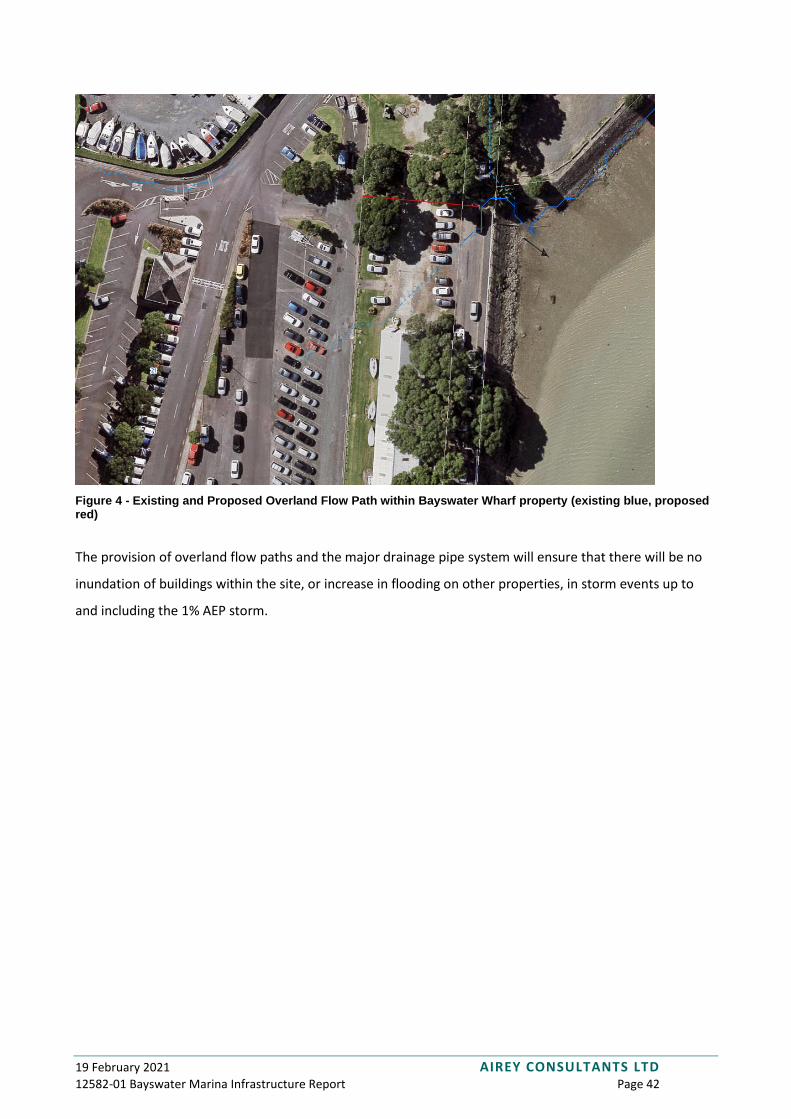
It should be noted that one overland flow path will exit the site’s eastern boundary and flow into the
neighbouring property. There is an existing overland flow path generated within the subject site and
flowing into this property, this will be replaced by the new overland flow path. The new flowpath is 25m
north of the existing flow path and will not result in any increase in nuisance, damage or inundation of the
neighbouring property.
19 February 2021 AIREY CONSULTANTS LTD 12582-01 Bayswater Marina Infrastructure Report Page 42
Figure 4 - Existing and Proposed Overland Flow Path within Bayswater Wharf property (existing blue, proposed red)
The provision of overland flow paths and the major drainage pipe system will ensure that there will be no
inundation of buildings within the site, or increase in flooding on other properties, in storm events up to
and including the 1% AEP storm.
19 February 2021 AIREY CONSULTANTS LTD 12582-01 Bayswater Marina Infrastructure Report Page 43
3.8 Wastewater
This section should be read in conjunction with the Airey Consultants wastewater drawings (sheets 500 –
520) attached in Appendix A.
3.8.1 Existing Wastewater
The existing wastewater infrastructure present on the site consists of:
• A public gravity pipeline running north along the eastern boundary of the site
• A public pump station located northeast of the site (within the neighbouring property owned by
Auckland Council)
• A private pump station located in the southern part of the site serving the ferry terminal and the
southern ablutions block
• Private gravity pipeline running from the northern ablutions block to the public gravity pipeline
• Private rising mains running from the southern pump station to the private gravity pipeline
The majority of the existing private wastewater within the site will be decommissioned and removed,
including the private pump station. The existing public gravity line running along the eastern boundary of
the site is proposed to be retained. The existing public pump station is proposed to be replaced with a new
pump station, refer to the Airey Consultants Pump Station report attached separately for further details
regarding this.
3.8.2 Proposed Wastewater
A new private wastewater reticulation system will be constructed to service the development. The new
wastewater reticulation will be a gravity system comprising pipes and manholes and will connect the three
precincts of the development to the existing wastewater pipeline that runs along Sir Peter Blake Parade
and which discharges into the existing pump station. A new upgraded public pump station is proposed to
be constructed to replace the existing public pump station and will pump wastewater through the existing
rising main to the existing gravity system located at Beresford Street. A capacity check of the existing rising
main and the downstream reticulation has confirmed that it has capacity to accept the increased flows
from the development. The capacity check calculations are attached as an appendix to the Airey
Consultants Pump Station report.
19 February 2021 AIREY CONSULTANTS LTD 12582-01 Bayswater Marina Infrastructure Report Page 44
The new pump station will continue to utilise the existing wastewater discharge consent for wastewater
overflows; but the conditions of this consent may need to be varied to suit the new, substantially larger,
pump station.
19 February 2021 AIREY CONSULTANTS LTD 12582-01 Bayswater Marina Infrastructure Report Page 45
3.9 Water Supply
This section should be read in conjunction with the Airey Consultants water supply drawings (sheets 600 –
604) attached in Appendix A.
3.9.1 Existing Water Supply
The existing water supply infrastructure within the site is predominantly private, with the exception of a
150mm diameter pipe and bulk meter supplying the property. A network of water supply pipes are fed
from this service lead and supply water to the ablutions blocks, ferry terminal and the marina berths. Three
fire hydrants are provided on the private network and are all located near the reclamation bund on the
western side of the site.
A public watermain runs along the eastern boundary of the site within the neighbouring property. This
watermain is fed by the public water supply reticulation from Bayswater Road and Lake Road, originating
from the reservoir on top of Takarunga/Mount Victoria. Three hydrants are provided on the public network
along the site boundary. The existing watermain will be retained and utilised to supply water to the
development.
3.9.2 Proposed Water Supply
It is proposed to utilise the existing bulk meter to supply water to the development. The meter will be
relocated and a new private water supply network will be constructed and connected to the bulk meter.
The private water supply network will consist of 100mm ID watermains located around the perimeter of
the site, with 50mm ID rider mains forming smaller loops around the three stages of the development.
Although the water supply network would be privately owned it would generally be designed and
constructed in accordance with Watercare standards.
Each terraced house will be provided with a property service connection and meter, and further bulk
meters and backflow prevention devices will be provided for the apartment buildings. Booster pumps may
be required for the apartment buildings to ensure adequate water pressures at the upper floors. Design will
be undertaken at the building consent stage for each individual apartment building. Privately owned fire
hydrants will be provided on the water supply network. The firefighting requirements are described in
more detail in section 3.9.3 below.

19 February 2021 AIREY CONSULTANTS LTD 12582-01 Bayswater Marina Infrastructure Report Page 46
3.9.3 Water Supply Fire Fighting
Under the New Zealand Fire Service Firefighting Water Supplies Code of Practice SNZ PAS 4509:2008, Table
1, the proposed development’s water supply classifications are determined as follows:
• Terraced houses – FW2
It is assumed that the terraced houses will not be provided with sprinklers
• Apartment buildings – FW2
The apartment buildings will be provided with sprinklers.
FW2 classification requires a minimum of 12.5L/s to be available within 135m of every dwelling, and an
additional 12.5L/s to be available within 270m for every dwelling, from a maximum of two hydrants. In
practical terms this means that one hydrant is required within 135m of every dwelling and one further
hydrant within 270m.
The existing public hydrants on the eastern boundary of the site have been pressure and flow tested and
meet the requirements for FW3 firefighting water supply classification, and therefore also meet the
requirements of FW2 firefighting water supply classification. The results of this test are included within
Appendix .
All existing hydrants on or adjacent to the site are proposed to be retained and will provide firefighting
service to the development.
One additional private hydrant is proposed to be constructed to provide additional firefighting security for
the development. This is shown on the Airey Consultants water supply drawings (12582-01-600 – 604).
19 February 2021 AIREY CONSULTANTS LTD 12582-01 Bayswater Marina Infrastructure Report Page 47
3.10 Utilities
3.10.1 Power and Telecommunications
The site is currently serviced by power and telecommunications running along Sir Peter Blake Parade and it
is anticipated that upgrades and modifications will be made to this infrastructure to enable it to service the
development. There are two Vector transformers within the site and one adjacent to the existing pump
station. The design of the electrical reticulation for the development will be undertaken at the engineering
approval/building consent stage by the project electrical engineer in conjunction with Vector.
Telecommunications infrastructure is also present within the site providing phone service to the marina
berths and buildings, as well as facilitating the fire alarm and security systems. These systems will be
required to be maintained for the duration of the construction works and upon completion of the
development. Design of the telecommunications reticulation for the development will be undertaken at the
engineering approval/building consent stage by the project electrical engineer in conjunction with Chorus.

19 February 2021 AIREY CONSULTANTS LTD 12582-01 Bayswater Marina Infrastructure Report Page 48
4 SUMMARY
The proposed development is considered feasible subject to the engineering works and infrastructure
upgrades/modifications described in this report, which will ensure that the development:
• Has habitable floor levels located above the projected coastal inundation levels taking into account
sea level rise.
• Can be staged in such a way to ensure that access and use of the existing marina berths is not
interrupted.
• Is provided with stormwater, wastewater, water supply and utility service connections.
• Does not result in adverse effects on the environment that are more than minor.
• Is provided with safe vehicle and pedestrian access to each dwelling.

19 February 2021 AIREY CONSULTANTS LTD 12582-01 Bayswater Marina Infrastructure Report Page 49
Appendix A
Drawings

19 February 2021 AIREY CONSULTANTS LTD 12582-01 Bayswater Marina Infrastructure Report Page 50
Appendix B
Calculations
ENGINEERING CALCULATIONS
Job: Hydraulic Neutrality Report
Location: Bayswater Maritime Precinct
Client: Bayswater Marina Holdings Ltd
Job No: 12582-01
Date: Dec 2020
Design Engineer: AW
Checked By: MR
Contact Phone: (09) 486 4542 Fax: (09) 489 5455
Email: [email protected]
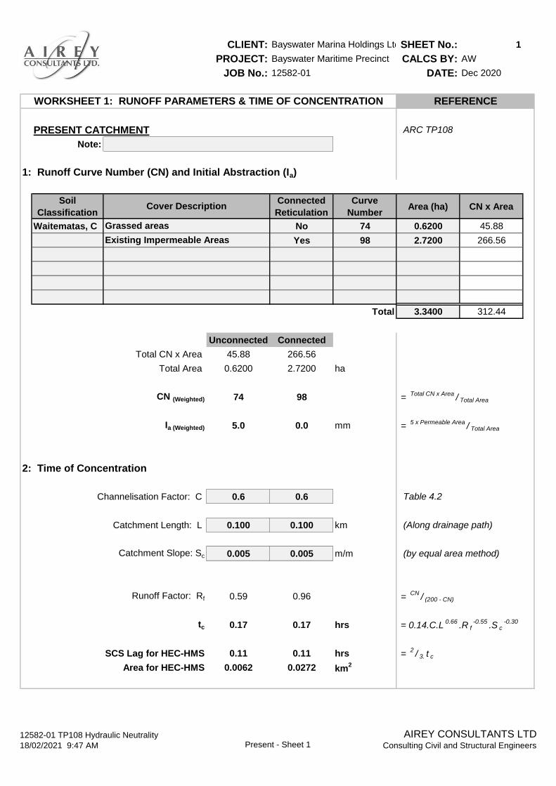
CLIENT: Bayswater Marina Holdings LtdSHEET No.: 1
PROJECT: Bayswater Maritime Precinct CALCS BY: AW
JOB No.: 12582-01 DATE: Dec 2020
PRESENT CATCHMENT ARC TP108
Note:
1: Runoff Curve Number (CN) and Initial Abstraction (Ia)
Soil
Classification
Connected
Reticulation
Curve
NumberArea (ha) CN x Area
Waitematas, C No 74 0.6200 45.88
Yes 98 2.7200 266.56
Total 3.3400 312.44
Unconnected Connected
Total CN x Area 45.88 266.56
Total Area 0.6200 2.7200 ha
CN (Weighted) 74 98 = Total CN x Area
/ Total Area
Ia (Weighted) 5.0 0.0 mm = 5 x Permeable Area
/ Total Area
2: Time of Concentration
Channelisation Factor: C 0.6 0.6 Table 4.2
Catchment Length: L 0.100 0.100 km (Along drainage path)
Catchment Slope: Sc 0.005 0.005 m/m (by equal area method)
Runoff Factor: Rf 0.59 0.96 = CN
/ (200 - CN)
tc 0.17 0.17 hrs = 0.14.C.L0.66
.R f-0.55
.S c-0.30
SCS Lag for HEC-HMS 0.11 0.11 hrs = 2/ 3. t c
Area for HEC-HMS 0.0062 0.0272 km2
WORKSHEET 1: RUNOFF PARAMETERS & TIME OF CONCENTRATION REFERENCE
Cover Description
Grassed areas
Existing Impermeable Areas
12582-01 TP108 Hydraulic Neutrality
18/02/2021 9:47 AM Present - Sheet 1
AIREY CONSULTANTS LTDConsulting Civil and Structural Engineers
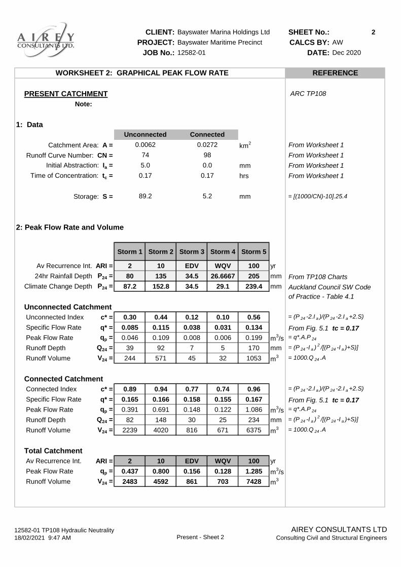
CLIENT: Bayswater Marina Holdings Ltd SHEET No.: 2
PROJECT: Bayswater Maritime Precinct CALCS BY: AW
JOB No.: 12582-01 DATE: Dec 2020
PRESENT CATCHMENT ARC TP108
Note:
1: Data
Catchment Area: A = km2 From Worksheet 1
Runoff Curve Number: CN = From Worksheet 1
Initial Abstraction: Ia = mm From Worksheet 1
Time of Concentration: tc = hrs From Worksheet 1
Storage: S = mm = [(1000/CN)-10].25.4
2: Peak Flow Rate and Volume
Storm 1 Storm 2 Storm 3 Storm 4 Storm 5
Av Recurrence Int. ARI = 2 10 EDV WQV 100 yr
24hr Rainfall Depth P24 = 80 135 34.5 26.6667 205 mm From TP108 Charts
Climate Change Depth P24 = 87.2 152.8 34.5 29.1 239.4 mm Auckland Council SW Code
of Practice - Table 4.1
Unconnected Catchment
Unconnected Index c* = 0.30 0.44 0.12 0.10 0.56 = (P 24 -2.I a )/(P 24 -2.I a +2.S)
Specific Flow Rate q* = 0.085 0.115 0.038 0.031 0.134 From Fig. 5.1 tc = 0.17
Peak Flow Rate qp = 0.046 0.109 0.008 0.006 0.199 m3/s = q*.A.P 24
Runoff Depth Q24 = 39 92 7 5 170 mm = (P 24 -I a )2/[(P 24 -I a )+S)]
Runoff Volume V24 = 244 571 45 32 1053 m3 = 1000.Q 24 .A
Connected Catchment
Connected Index c* = 0.89 0.94 0.77 0.74 0.96 = (P 24 -2.I a )/(P 24 -2.I a +2.S)
Specific Flow Rate q* = 0.165 0.166 0.158 0.155 0.167 From Fig. 5.1 tc = 0.17
Peak Flow Rate qp = 0.391 0.691 0.148 0.122 1.086 m3/s = q*.A.P 24
Runoff Depth Q24 = 82 148 30 25 234 mm = (P 24 -I a )2/[(P 24 -I a )+S)]
Runoff Volume V24 = 2239 4020 816 671 6375 m3 = 1000.Q 24 .A
Total Catchment
Av Recurrence Int. ARI = 2 10 EDV WQV 100 yr
Peak Flow Rate qp = 0.437 0.800 0.156 0.128 1.285 m3/s
Runoff Volume V24 = 2483 4592 861 703 7428 m3
WORKSHEET 2: GRAPHICAL PEAK FLOW RATE REFERENCE
0.17
5.2
Unconnected
0.0062
74
5.0
0.17
89.2
Connected
0.0272
98
0.0
12582-01 TP108 Hydraulic Neutrality
18/02/2021 9:47 AM Present - Sheet 2
AIREY CONSULTANTS LTDConsulting Civil and Structural Engineers

CLIENT: Bayswater Marina Holdings LtdSHEET No.: 3
PROJECT: Bayswater Maritime Precinct CALCS BY: AW
JOB No.: 12582-01 DATE: Dec 2020
DEVELOPED CATCHMENT ARC TP108
Note:
1: Runoff Curve Number (CN) and Initial Abstraction (Ia)
Soil
Classification
Connected
Reticulation
Curve
NumberArea (ha) CN x Area
Waitematas, C No 74 0.7530 55.72
Yes 98 2.5870 253.53
Total 3.3400 309.25
Unconnected Connected
Total CN x Area 55.72 253.53
Total Area 0.7530 2.5870 ha
CN (Weighted) 74 98 = Total CN x Area
/ Total Area
Ia (Weighted) 5.0 0.0 mm = 5 x Permeable Area
/ Total Area
2: Time of Concentration
Channelisation Factor: C 0.6 0.6 Table 4.2
Catchment Length: L 0.100 0.100 km (Along drainage path)
Catchment Slope: Sc 0.005 0.005 m/m (by equal area method)
Runoff Factor: Rf 0.59 0.96 = CN
/ (200 - CN)
tc 0.17 0.17 hrs = 0.14.C.L0.66
.R f-0.55
.S c-0.30
SCS Lag for HEC-HMS 0.11 0.11 hrs = 2/ 3. t c
Area for HEC-HMS 0.0075 0.0259 km2
REFERENCE
Cover Description
Proposed Grassed Areas
Proposed Impermeable Areas
WORKSHEET 1: RUNOFF PARAMETERS & TIME OF CONCENTRATION
12582-01 TP108 Hydraulic Neutrality
18/02/2021 9:47 AM Developed - Sheet 1
AIREY CONSULTANTS LTDConsulting Civil and Structural Engineers

CLIENT: Bayswater Marina Holdings Ltd SHEET No.: 4
PROJECT: Bayswater Maritime Precinct CALCS BY: AW
JOB No.: 12582-01 DATE: Dec 2020
DEVELOPED CATCHMENT ARC TP108
Note:
1: Data
Catchment Area: A = km2 From Worksheet 1
Runoff Curve Number: CN = From Worksheet 1
Initial Abstraction: Ia = mm From Worksheet 1
Time of Concentration: tc = hrs From Worksheet 1
Storage: S = mm = [(1000/CN)-10].25.4
2: Peak Flow Rate and Volume
Storm 1 Storm 2 Storm 3 Storm 4 Storm 5
Av Recurrence Int. ARI = 2 10 EDV WQV 100 yr
24hr Rainfall Depth P24 = 87.2 152.8 34.5 29.1 239.4 mm From TP108 Charts
Unconnected Catchment
Unconnected Index c* = 0.30 0.44 0.12 0.10 0.56 = (P 24 -2.I a )/(P 24 -2.I a +2.S)
Specific Flow Rate q* = 0.085 0.115 0.038 0.031 0.134 From Fig. 5.1 tc = 0.17
Peak Flow Rate qp = 0.056 0.132 0.010 0.007 0.242 m3/s = q*.A.P 24
Runoff Depth Q24 = 39 92 7 5 170 mm = (P 24 -I a )2/[(P 24 -I a )+S)]
Runoff Volume V24 = 297 694 55 38 1279 m3 = 1000.Q 24 .A
Connected Catchment
Connected Index c* = 0.89 0.94 0.77 0.74 0.96 = (P 24 -2.I a )/(P 24 -2.I a +2.S)
Specific Flow Rate q* = 0.165 0.166 0.158 0.155 0.167 From Fig. 5.1 tc = 0.17
Peak Flow Rate qp = 0.372 0.657 0.141 0.116 1.033 m3/s = q*.A.P 24
Runoff Depth Q24 = 82 148 30 25 234 mm = (P 24 -I a )2/[(P 24 -I a )+S)]
Runoff Volume V24 = 2129 3824 776 638 6063 m3 = 1000.Q 24 .A
Total Catchment
Av Recurrence Int. ARI = 2 10 EDV WQV 100 yr
Peak Flow Rate qp = 0.428 0.789 0.150 0.123 1.275 m3/s
Runoff Volume V24 = 2426 4518 831 677 7342 m3
0.0075 0.0259
WORKSHEET 2: GRAPHICAL PEAK FLOW RATE REFERENCE
Unconnected Connected
89.2 5.2
74 98
5.0 0.0
0.17 0.17
12582-01 TP108 Hydraulic Neutrality
18/02/2021 9:47 AM Developed - Sheet 2
AIREY CONSULTANTS LTDConsulting Civil and Structural Engineers

CLIENT: Bayswater Marina Holdings Ltd SHEET No.: 5
PROJECT: Bayswater Maritime Precinct CALCS BY: AW
JOB No.: 12582-01 DATE: Dec 2020
PRESENT - DEVELOPED SUMMARY
1: Data
Present: A = ha
Developed: A = ha
Percentage Difference
Difference: A = ha
Present: A =
Developed: A =
Storm 1 Storm 2 Storm 3 Storm 4 Storm 5
Av Recurrence Int. ARI = 2 10 EDV WQV 100 yr
24hr Rainfall Depth P24 = 87.2 152.8 34.5 29.1 239.4 mm
2: Peak Flow Rate Summary
Av Recurrence Int. ARI = 2 10 EDV WQV 100 yr
Present Peak Flow qp = 0.437 0.800 0.156 0.128 1.285 m3/s
Developed Peak Flow qp = 0.428 0.789 0.150 0.123 1.275 m3/s
Percentage Difference 98% 99% 96% 96% 99%
Peak Flow Difference q = -0.009 -0.010 -0.005 -0.005 -0.010 m3/s
3: Runoff Volume Summary
Av Recurrence Int. ARI = 2 10 EDV WQV 100 yr
Present Volume V24 = 2483 4592 861 703 7428 m3
Developed Volume V24 = 2426 4518 831 677 7342 m3
Percentage Difference 98% 98% 97% 96% 99%
Volume Difference V = -57 -74 -30 -26 -86 m3
HYDRAULIC NEUTRALITY REPORT SUMMARY REFERENCE
Catchment Area
3.3400
77%
81%
100%
0.0000
3.3400
% Impermeable
12582-01 TP108 Hydraulic Neutrality
18/02/2021 9:47 AM Summary
AIREY CONSULTANTS LTDConsulting Civil and Structural Engineers
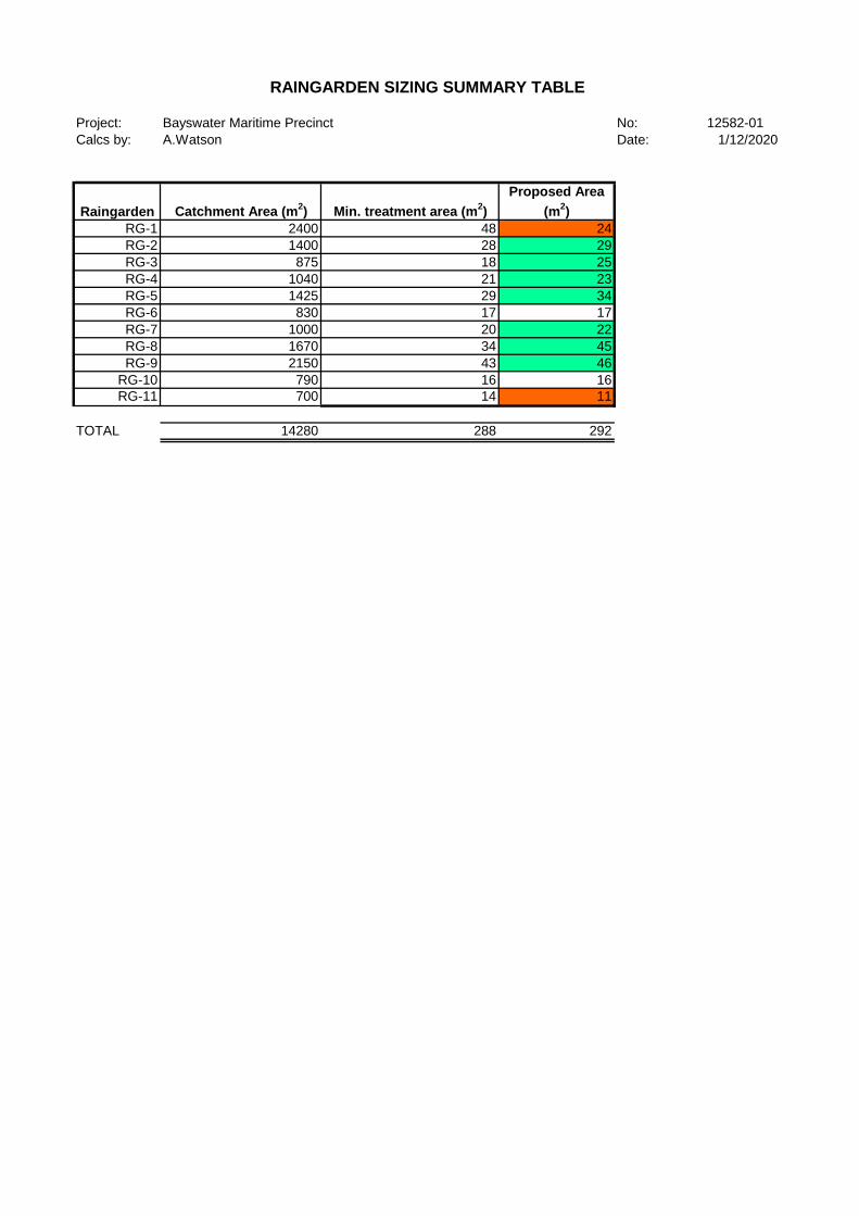
Project: Bayswater Maritime Precinct No: 12582-01
Calcs by: A.Watson Date: 1/12/2020
Raingarden Catchment Area (m2) Min. treatment area (m
2)
Proposed Area
(m2)
RG-1 2400 48 24
RG-2 1400 28 29
RG-3 875 18 25
RG-4 1040 21 23
RG-5 1425 29 34
RG-6 830 17 17
RG-7 1000 20 22
RG-8 1670 34 45
RG-9 2150 43 46
RG-10 790 16 16
RG-11 700 14 11
TOTAL 14280 288 292
RAINGARDEN SIZING SUMMARY TABLE

CLIENT: Empire Capital
PROJECT: Bayswater Marina
JOB No.: 12582-01
SHEET No.: 2
CALCS. BY: AW
DATE: MAR 2020
RG-1 REFERENCE
Treatment Requirements ARC GD01; Section C3
Area to be treated A(connect) = 2400.0 m2 Rational Method Inputs
0.2 ha
Coefficient C= 0.95 Roofed, paved, imp areas
Time of Concentration Tc = 10.0 mins
Rainfall Intensity i = 10.0 mm/hr
Water Quality Flow WQF = 22.8 m3/hr Q=2.78*C*I*A
Minimum Device Area
Infiltration Rate K(media) = 1.0 m/hr
Clogging Safety Factor 0.5
Minimum Area Required 45.64 m2 >2% of Catchment Area
2% of Catchment Area 48.00 m2 Check
Required Device Area 48.0 m2
For Treatment:
Ponding Depth d(pond) = 100 mm ≥100mm
Media Depth d(media) = 500 mm ≥500mm
Transition Layer 100 mm 100mm
Drainage Layer d(drainage) = 250 mm ≥200-300mm
Void Space Assumptions
Ponding Layer 100%
Bioretention Layer 30%
Transition Layer 30%
Drainage Layer 35%
RAINGARDEN CALCULATIONS
18/02/2021 9:47 AM
12582-01 Raingardens RG-1AIREY CONSULTANTS LTD
Consulting Civil and Structural Engineers

CLIENT: Empire Capital
PROJECT: Bayswater Marina
JOB No.: 12582-01
SHEET No.: 3
CALCS. BY: AW
DATE: MAR 2020
RG-2 REFERENCE
Treatment Requirements ARC GD01; Section C3
Area to be treated A(connect) = 1400.0 m2 Rational Method Inputs
0.1 ha
Coefficient C= 0.95 Roofed, paved, imp areas
Time of Concentration Tc = 10.0 mins
Rainfall Intensity i = 10.0 mm/hr
Water Quality Flow WQF = 13.3 m3/hr Q=2.78*C*I*A
Minimum Device Area
Infiltration Rate K(media) = 1.0 m/hr
Clogging Safety Factor 0.5
Minimum Area Required 26.62 m2 >2% of Catchment Area
2% of Catchment Area 28.00 m2 Check
Required Device Area 28.0 m2
For Treatment:
Ponding Depth d(pond) = 100 mm ≥100mm
Media Depth d(media) = 500 mm ≥500mm
Transition Layer 100 mm 100mm
Drainage Layer d(drainage) = 250 mm ≥200-300mm
Void Space Assumptions
Ponding Layer 100%
Bioretention Layer 30%
Transition Layer 30%
Drainage Layer 35%
RAINGARDEN CALCULATIONS
18/02/2021 9:47 AM
12582-01 Raingardens RG-2AIREY CONSULTANTS LTD
Consulting Civil and Structural Engineers

CLIENT: Empire Capital
PROJECT: Bayswater Marina
JOB No.: 12582-01
SHEET No.: 4
CALCS. BY: AW
DATE: MAR 2020
RG-3 REFERENCE
Treatment Requirements ARC GD01; Section C3
Area to be treated A(connect) = 875.0 m2 Rational Method Inputs
0.1 ha
Coefficient C= 0.95 Roofed, paved, imp areas
Time of Concentration Tc = 10.0 mins
Rainfall Intensity i = 10.0 mm/hr
Water Quality Flow WQF = 8.3 m3/hr Q=2.78*C*I*A
Minimum Device Area
Infiltration Rate K(media) = 1.0 m/hr
Clogging Safety Factor 0.5
Minimum Area Required 16.64 m2 >2% of Catchment Area
2% of Catchment Area 17.50 m2 Check
Required Device Area 18.0 m2
For Treatment:
Ponding Depth d(pond) = 100 mm ≥100mm
Media Depth d(media) = 500 mm ≥500mm
Transition Layer 100 mm 100mm
Drainage Layer d(drainage) = 250 mm ≥200-300mm
Void Space Assumptions
Ponding Layer 100%
Bioretention Layer 30%
Transition Layer 30%
Drainage Layer 35%
RAINGARDEN CALCULATIONS
18/02/2021 9:47 AM
12582-01 Raingardens RG-3AIREY CONSULTANTS LTD
Consulting Civil and Structural Engineers

CLIENT: Empire Capital
PROJECT: Bayswater Marina
JOB No.: 12582-01
SHEET No.: 5
CALCS. BY: AW
DATE: MAR 2020
RG-4 REFERENCE
Treatment Requirements ARC GD01; Section C3
Area to be treated A(connect) = 1040.0 m2 Rational Method Inputs
0.1 ha
Coefficient C= 0.95 Roofed, paved, imp areas
Time of Concentration Tc = 10.0 mins
Rainfall Intensity i = 10.0 mm/hr
Water Quality Flow WQF = 9.9 m3/hr Q=2.78*C*I*A
Minimum Device Area
Infiltration Rate K(media) = 1.0 m/hr
Clogging Safety Factor 0.5
Minimum Area Required 19.78 m2 >2% of Catchment Area
2% of Catchment Area 20.80 m2 Check
Required Device Area 21.0 m2
For Treatment:
Ponding Depth d(pond) = 100 mm ≥100mm
Media Depth d(media) = 500 mm ≥500mm
Transition Layer 100 mm 100mm
Drainage Layer d(drainage) = 250 mm ≥200-300mm
Void Space Assumptions
Ponding Layer 100%
Bioretention Layer 30%
Transition Layer 30%
Drainage Layer 35%
RAINGARDEN CALCULATIONS
18/02/2021 9:47 AM
12582-01 Raingardens RG-4AIREY CONSULTANTS LTD
Consulting Civil and Structural Engineers

CLIENT: Empire Capital
PROJECT: Bayswater Marina
JOB No.: 12582-01
SHEET No.: 6
CALCS. BY: AW
DATE: MAR 2020
RG-5 REFERENCE
Treatment Requirements ARC GD01; Section C3
Area to be treated A(connect) = 1425.0 m2 Rational Method Inputs
0.1 ha
Coefficient C= 0.95 Roofed, paved, imp areas
Time of Concentration Tc = 10.0 mins
Rainfall Intensity i = 10.0 mm/hr
Water Quality Flow WQF = 13.5 m3/hr Q=2.78*C*I*A
Minimum Device Area
Infiltration Rate K(media) = 1.0 m/hr
Clogging Safety Factor 0.5
Minimum Area Required 27.10 m2 >2% of Catchment Area
2% of Catchment Area 28.50 m2 Check
Required Device Area 29.0 m2
For Treatment:
Ponding Depth d(pond) = 100 mm ≥100mm
Media Depth d(media) = 500 mm ≥500mm
Transition Layer 100 mm 100mm
Drainage Layer d(drainage) = 250 mm ≥200-300mm
Void Space Assumptions
Ponding Layer 100%
Bioretention Layer 30%
Transition Layer 30%
Drainage Layer 35%
RAINGARDEN CALCULATIONS
18/02/2021 9:47 AM
12582-01 Raingardens RG-5AIREY CONSULTANTS LTD
Consulting Civil and Structural Engineers
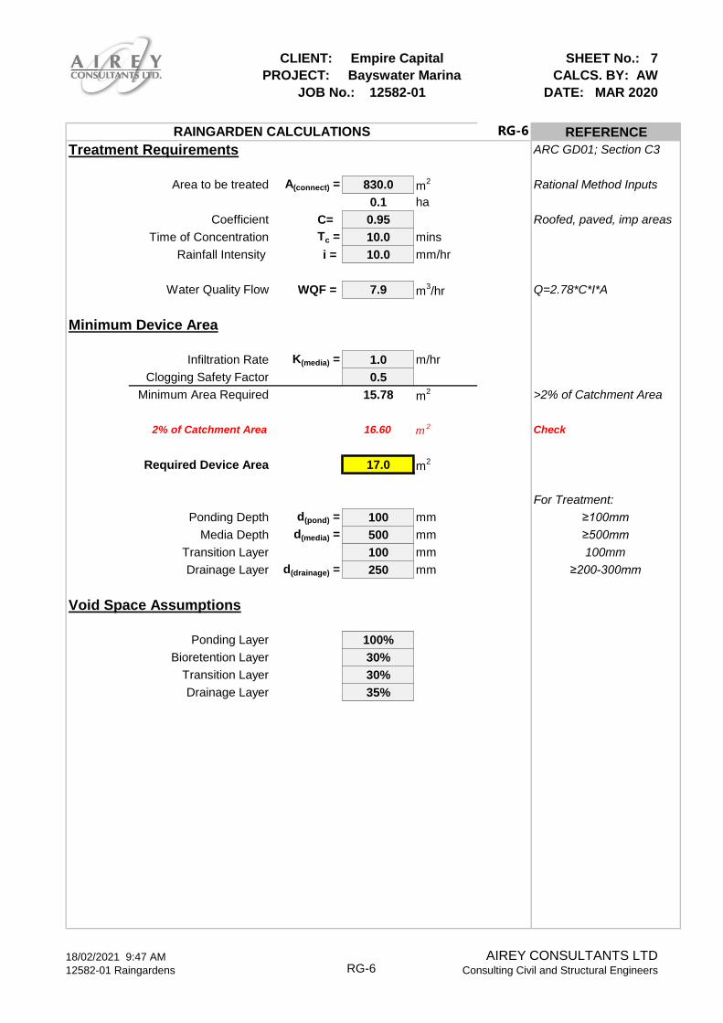
CLIENT: Empire Capital
PROJECT: Bayswater Marina
JOB No.: 12582-01
SHEET No.: 7
CALCS. BY: AW
DATE: MAR 2020
RG-6 REFERENCE
Treatment Requirements ARC GD01; Section C3
Area to be treated A(connect) = 830.0 m2 Rational Method Inputs
0.1 ha
Coefficient C= 0.95 Roofed, paved, imp areas
Time of Concentration Tc = 10.0 mins
Rainfall Intensity i = 10.0 mm/hr
Water Quality Flow WQF = 7.9 m3/hr Q=2.78*C*I*A
Minimum Device Area
Infiltration Rate K(media) = 1.0 m/hr
Clogging Safety Factor 0.5
Minimum Area Required 15.78 m2 >2% of Catchment Area
2% of Catchment Area 16.60 m2 Check
Required Device Area 17.0 m2
For Treatment:
Ponding Depth d(pond) = 100 mm ≥100mm
Media Depth d(media) = 500 mm ≥500mm
Transition Layer 100 mm 100mm
Drainage Layer d(drainage) = 250 mm ≥200-300mm
Void Space Assumptions
Ponding Layer 100%
Bioretention Layer 30%
Transition Layer 30%
Drainage Layer 35%
RAINGARDEN CALCULATIONS
18/02/2021 9:47 AM
12582-01 Raingardens RG-6AIREY CONSULTANTS LTD
Consulting Civil and Structural Engineers

CLIENT: Empire Capital
PROJECT: Bayswater Marina
JOB No.: 12582-01
SHEET No.: 8
CALCS. BY: AW
DATE: MAR 2020
RG-7 REFERENCE
Treatment Requirements ARC GD01; Section C3
Area to be treated A(connect) = 1000.0 m2 Rational Method Inputs
0.1 ha
Coefficient C= 0.95 Roofed, paved, imp areas
Time of Concentration Tc = 10.0 mins
Rainfall Intensity i = 10.0 mm/hr
Water Quality Flow WQF = 9.5 m3/hr Q=2.78*C*I*A
Minimum Device Area
Infiltration Rate K(media) = 1.0 m/hr
Clogging Safety Factor 0.5
Minimum Area Required 19.02 m2 >2% of Catchment Area
2% of Catchment Area 20.00 m2 Check
Required Device Area 20.0 m2
For Treatment:
Ponding Depth d(pond) = 150 mm ≥100mm
Media Depth d(media) = 500 mm ≥500mm
Transition Layer 100 mm 100mm
Drainage Layer d(drainage) = 250 mm ≥200-300mm
Void Space Assumptions
Ponding Layer 100%
Bioretention Layer 30%
Transition Layer 30%
Drainage Layer 35%
RAINGARDEN CALCULATIONS
18/02/2021 9:47 AM
12582-01 Raingardens RG-7AIREY CONSULTANTS LTD
Consulting Civil and Structural Engineers

CLIENT: Empire Capital
PROJECT: Bayswater Marina
JOB No.: 12582-01
SHEET No.: 9
CALCS. BY: AW
DATE: MAR 2020
RG-8 REFERENCE
Treatment Requirements ARC GD01; Section C3
Area to be treated A(connect) = 1670.0 m2 Rational Method Inputs
0.2 ha
Coefficient C= 0.95 Roofed, paved, imp areas
Time of Concentration Tc = 10.0 mins
Rainfall Intensity i = 10.0 mm/hr
Water Quality Flow WQF = 15.9 m3/hr Q=2.78*C*I*A
Minimum Device Area
Infiltration Rate K(media) = 1.0 m/hr
Clogging Safety Factor 0.5
Minimum Area Required 31.76 m2 >2% of Catchment Area
2% of Catchment Area 33.40 m2 Check
Required Device Area 34.0 m2
For Treatment:
Ponding Depth d(pond) = 100 mm ≥100mm
Media Depth d(media) = 500 mm ≥500mm
Transition Layer 100 mm 100mm
Drainage Layer d(drainage) = 250 mm ≥200-300mm
Void Space Assumptions
Ponding Layer 100%
Bioretention Layer 30%
Transition Layer 30%
Drainage Layer 35%
RAINGARDEN CALCULATIONS
18/02/2021 9:47 AM
12582-01 Raingardens RG-8AIREY CONSULTANTS LTD
Consulting Civil and Structural Engineers
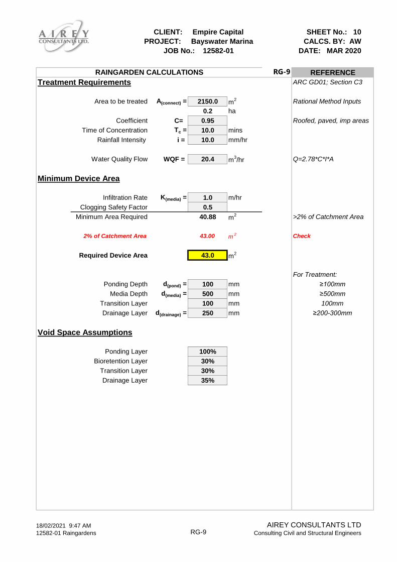
CLIENT: Empire Capital
PROJECT: Bayswater Marina
JOB No.: 12582-01
SHEET No.: 10
CALCS. BY: AW
DATE: MAR 2020
RG-9 REFERENCE
Treatment Requirements ARC GD01; Section C3
Area to be treated A(connect) = 2150.0 m2 Rational Method Inputs
0.2 ha
Coefficient C= 0.95 Roofed, paved, imp areas
Time of Concentration Tc = 10.0 mins
Rainfall Intensity i = 10.0 mm/hr
Water Quality Flow WQF = 20.4 m3/hr Q=2.78*C*I*A
Minimum Device Area
Infiltration Rate K(media) = 1.0 m/hr
Clogging Safety Factor 0.5
Minimum Area Required 40.88 m2 >2% of Catchment Area
2% of Catchment Area 43.00 m2 Check
Required Device Area 43.0 m2
For Treatment:
Ponding Depth d(pond) = 100 mm ≥100mm
Media Depth d(media) = 500 mm ≥500mm
Transition Layer 100 mm 100mm
Drainage Layer d(drainage) = 250 mm ≥200-300mm
Void Space Assumptions
Ponding Layer 100%
Bioretention Layer 30%
Transition Layer 30%
Drainage Layer 35%
RAINGARDEN CALCULATIONS
18/02/2021 9:47 AM
12582-01 Raingardens RG-9AIREY CONSULTANTS LTD
Consulting Civil and Structural Engineers

CLIENT: Empire Capital
PROJECT: Bayswater Marina
JOB No.: 12582-01
SHEET No.: 11
CALCS. BY: AW
DATE: MAR 2020
RG-10 REFERENCE
Treatment Requirements ARC GD01; Section C3
Area to be treated A(connect) = 790.0 m2 Rational Method Inputs
0.1 ha
Coefficient C= 0.95 Roofed, paved, imp areas
Time of Concentration Tc = 10.0 mins
Rainfall Intensity i = 10.0 mm/hr
Water Quality Flow WQF = 7.5 m3/hr Q=2.78*C*I*A
Minimum Device Area
Infiltration Rate K(media) = 1.0 m/hr
Clogging Safety Factor 0.5
Minimum Area Required 15.02 m2 >2% of Catchment Area
2% of Catchment Area 15.80 m2 Check
Required Device Area 16.0 m2
For Treatment:
Ponding Depth d(pond) = 100 mm ≥100mm
Media Depth d(media) = 500 mm ≥500mm
Transition Layer 100 mm 100mm
Drainage Layer d(drainage) = 250 mm ≥200-300mm
Void Space Assumptions
Ponding Layer 100%
Bioretention Layer 30%
Transition Layer 30%
Drainage Layer 35%
RAINGARDEN CALCULATIONS
18/02/2021 9:47 AM
12582-01 Raingardens RG-10AIREY CONSULTANTS LTD
Consulting Civil and Structural Engineers

CLIENT: Empire Capital
PROJECT: Bayswater Marina
JOB No.: 12582-01
SHEET No.: 12
CALCS. BY: AW
DATE: MAR 2020
RG-11 REFERENCE
Treatment Requirements ARC GD01; Section C3
Area to be treated A(connect) = 700.0 m2 Rational Method Inputs
0.1 ha
Coefficient C= 0.95 Roofed, paved, imp areas
Time of Concentration Tc = 10.0 mins
Rainfall Intensity i = 10.0 mm/hr
Water Quality Flow WQF = 6.7 m3/hr Q=2.78*C*I*A
Minimum Device Area
Infiltration Rate K(media) = 1.0 m/hr
Clogging Safety Factor 0.5
Minimum Area Required 13.31 m2 >2% of Catchment Area
2% of Catchment Area 14.00 m2 Check
Required Device Area 14.0 m2
For Treatment:
Ponding Depth d(pond) = 100 mm ≥100mm
Media Depth d(media) = 500 mm ≥500mm
Transition Layer 100 mm 100mm
Drainage Layer d(drainage) = 250 mm ≥200-300mm
Void Space Assumptions
Ponding Layer 100%
Bioretention Layer 30%
Transition Layer 30%
Drainage Layer 35%
RAINGARDEN CALCULATIONS
18/02/2021 9:47 AM
12582-01 Raingardens RG-11AIREY CONSULTANTS LTD
Consulting Civil and Structural Engineers

HY-8 Culvert Analysis Report

Water Surface Profile Plot for Culvert: South 1.6m MHWS
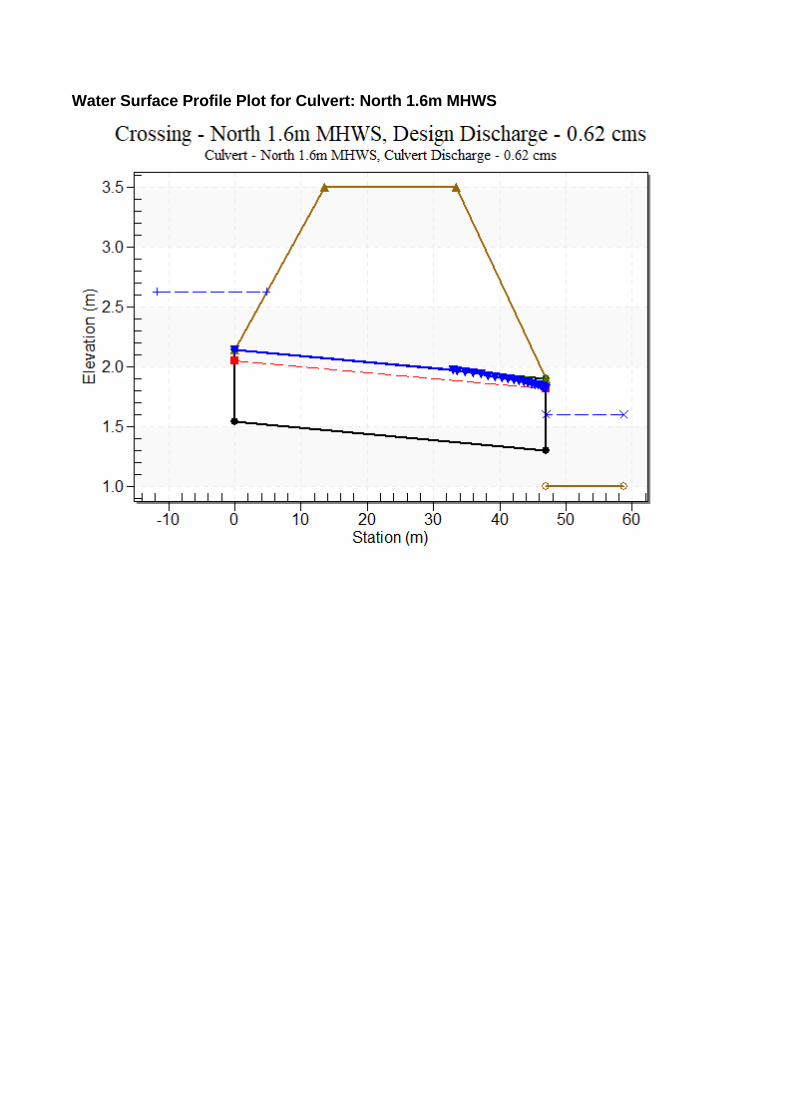
Water Surface Profile Plot for Culvert: North 1.6m MHWS
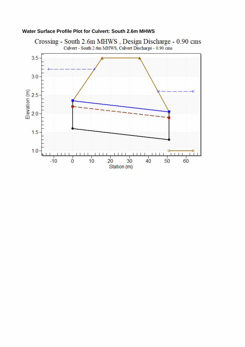
Water Surface Profile Plot for Culvert: South 2.6m MHWS

Water Surface Profile Plot for Culvert: North 2.6m MHWS

19 February 2021 AIREY CONSULTANTS LTD 12582-01 Bayswater Marina Infrastructure Report Page 51
Appendix C
Water Supply Flow & Pressure Testing

Jeremie Hooi Civil Engineer Airey Consultants Ltd Level 8 19 Como Street Takapuna 27th July 2018
RESULTS OF A FIRE FLOW TEST AT BAYSWATER MARINA BAYSWATER Wednesday 25th July 2018
Tim a’Beckett Con Iftimie David Iftimie
Background
The proposed residential development at Bayswater Marina, requires adequate fire protection that meets the Fire Service Code of Practice.
Prior to commencement of the Project, Airey Consultants Ltd requested Detection Services to test the mains surrounding the property to evaluate the potential to provide sufficient water to satisfy the fire requirements for the development. Airey Consultants advised that this development is classified FW3. The firefighting code of practice stipulates that the minimum requirement for a FW3 Development is a flow of 25l/s from a hydrant within 135m of the development, and a further flow of 25l/s from an additional hydrant within a distance of 270m. WaterCare require a minimum residual pressure of 200 kPa, measured at the next nearest FH.
Detection Services are competent to undertake such testing. Procedure Three fire hydrants were identified as suitable for undertaking the flow test on Sir Peter Blake Parade as per the diagram below.
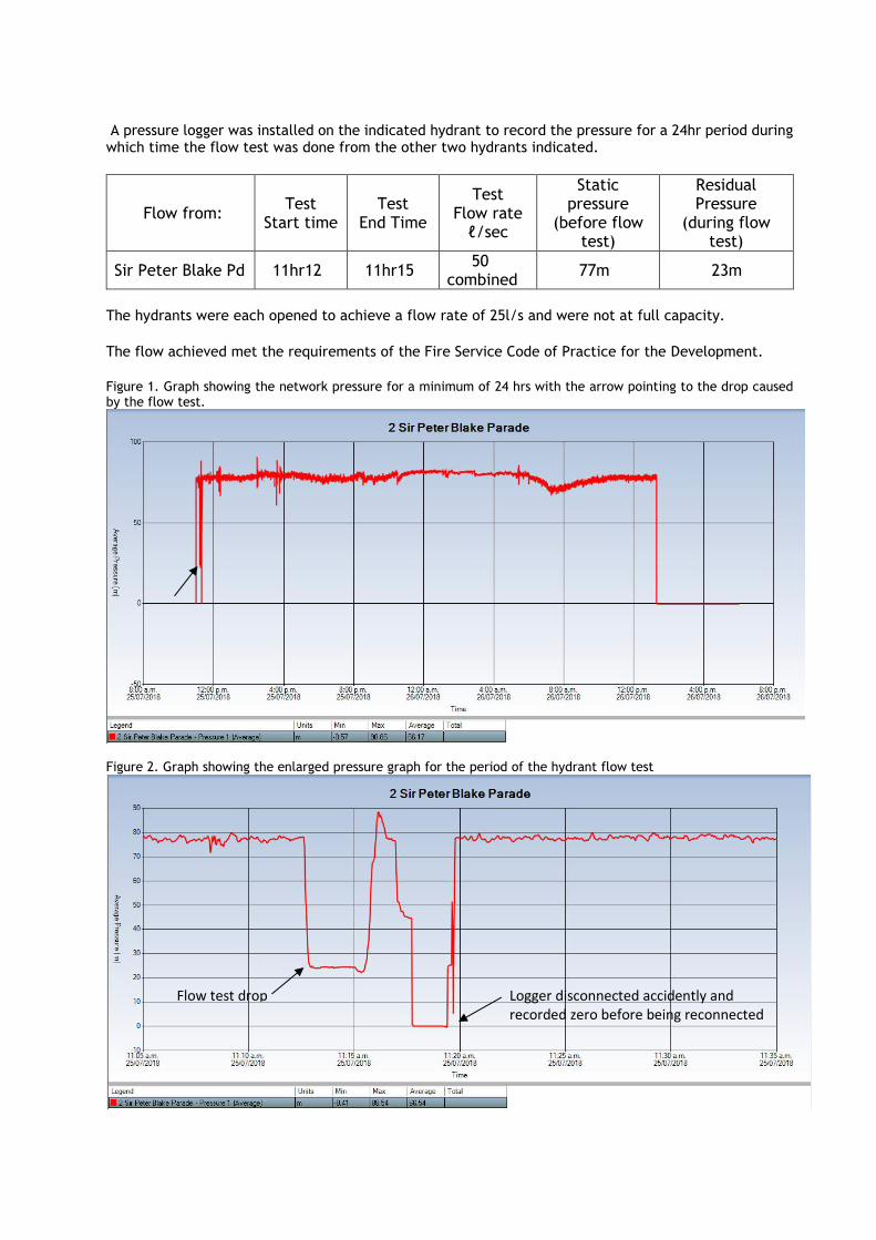
A pressure logger was installed on the indicated hydrant to record the pressure for a 24hr period during which time the flow test was done from the other two hydrants indicated.
Flow from: Test
Start time Test
End Time
Test Flow rate
ℓ/sec
Static pressure
(before flow test)
Residual Pressure
(during flow test)
Sir Peter Blake Pd 11hr12 11hr15 50 combined
77m 23m
The hydrants were each opened to achieve a flow rate of 25l/s and were not at full capacity. The flow achieved met the requirements of the Fire Service Code of Practice for the Development.
Figure 1. Graph showing the network pressure for a minimum of 24 hrs with the arrow pointing to the drop caused by the flow test.
Figure 2. Graph showing the enlarged pressure graph for the period of the hydrant flow test
Flow test drop Logger disconnected accidently and recorded zero before being reconnected

The test was successful. Acknowledgement Detection Services appreciates the opportunity to undertake these tests on behalf of Airey Consultants. Tim a’Beckett (mob 027 5518133) Detection Services P O Box 58951 The Hub, Botany Auckland.

19 February 2021 AIREY CONSULTANTS LTD 12582-01 Bayswater Marina Infrastructure Report Page 52
Appendix D
Water Supply/Wastewater Planning Assessment

DQ004-13092016
Development Application Form – Water Supply/Wastewater Planning Assessment Date of Application 15/01/2021
Address of Development 21 Sir Peter Blake Parade, Bayswater
Layout Plan of Proposed Development clearly showing: • Aerial photograph
• Road names
• Boundary of development
• Preferred point of connection to existing water supply and wastewater asset
INCUDED IN REPORT
Description Comment
Current Land Use Marina, including offices and liveaboard facilities
Proposed Land Use Residential with minor commercial and wet retail
Total Development Area (Ha.) 3.2 Ha
Number of Residential Households (Consent & Ultimate)
121 Three apartment buildings with 9 apartments each, plus 94 terrace houses
Refer to Water and Wastewater Code of Practice for Land Development and Subdivision Section 6 Water Supply
Water Supply Development Assessment
Average and Peak Residential Demand (L/s)
0.91 l/s average 2.26 l/s peak
Average and Peak Non-Residential Demand (L/s)
0.02 l/s average 0.05 l/s peak
Non Residential Demand Typical Daily Consumption Profile / Trend
N/A This is not considered necessary due to the very small areas/demands involved
Fire- fighting Classification required by the proposed site
FW2 Refer to New Zealand Standard SNZ PAS 4509:2008
Hydrant Flow Test Results ☒ Yes ☐ No
Attach hydrant flow test layout plan and results showing test date & time; location of hydrants tested and pressure logged; static pressure; flow; residual pressure
Sprinkler System in building? ☒ Yes ☐ No (in apartment buildings)
Sprinkler design should consider Watercare Level of Service: minimum pressure at 200kPa and minimum flow at 25 l/min. The building owner shall conduct periodic review of sprinkler design.
Further Water Supply comments
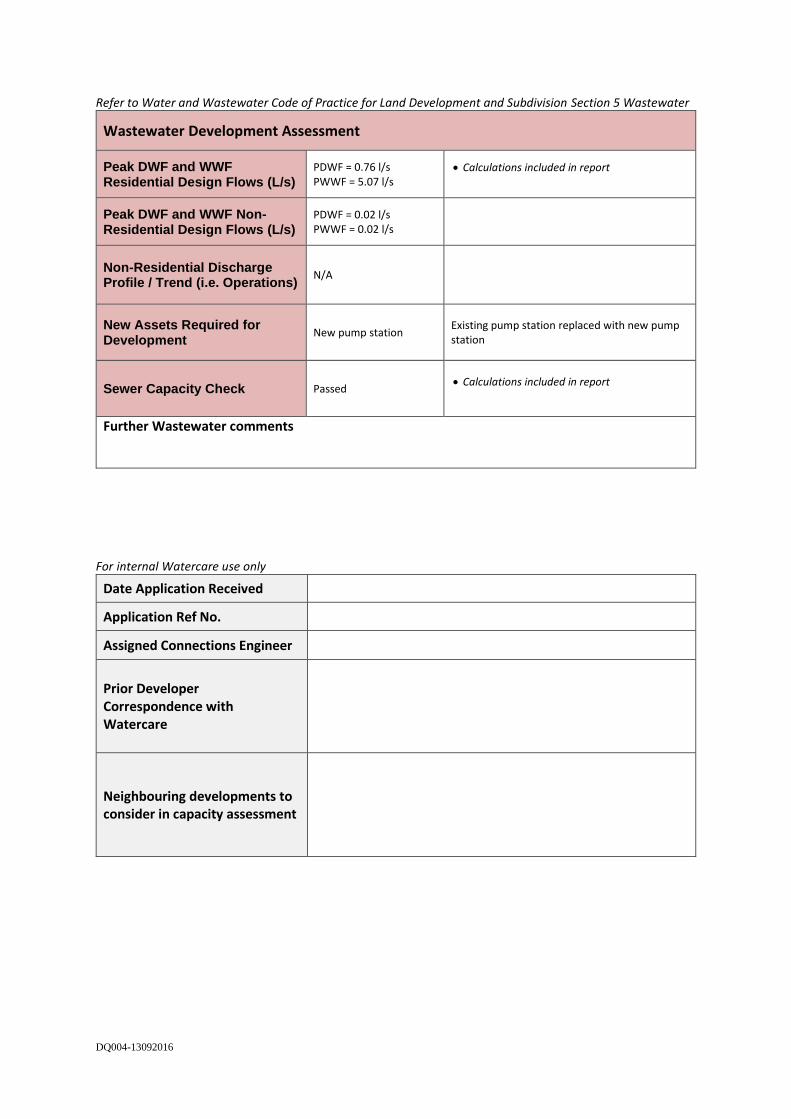
DQ004-13092016
Refer to Water and Wastewater Code of Practice for Land Development and Subdivision Section 5 Wastewater
Wastewater Development Assessment
Peak DWF and WWF Residential Design Flows (L/s)
PDWF = 0.76 l/s PWWF = 5.07 l/s
• Calculations included in report
Peak DWF and WWF Non-Residential Design Flows (L/s)
PDWF = 0.02 l/s PWWF = 0.02 l/s
Non-Residential Discharge Profile / Trend (i.e. Operations)
N/A
New Assets Required for Development
New pump station Existing pump station replaced with new pump station
Sewer Capacity Check Passed • Calculations included in report
Further Wastewater comments
For internal Watercare use only
Date Application Received
Application Ref No.
Assigned Connections Engineer
Prior Developer Correspondence with Watercare
Neighbouring developments to consider in capacity assessment