engineering and development standards - …government/... · o all note text changed to capital...
TRANSCRIPT

CORPORATION OF THE CITY OF THUNDER BAY
2014 EDITION
INFRASTRUCTURE AND OPERATIONS DEPARTMENT ENGINEERING DIVISION OFFICE
THUNDER BAY, ONTARIO
ENGINEERING
AND
DEVELOPMENT
STANDARDS

CITY OF THUNDER BAY ENGINEERING AND DEVELOPMENT STANDARDS
FREE WEB ACCESS!! The 2014 edition of the City of Thunder Bay Engineering and Development Standards and contract specification documents have been prepared and are available on the City’s Web site at: www.thunderbay.ca To access select “DEPARTMENTS” then scroll down to “INFRASTRUCTURE AND OPERATIONS” and select “MORE”. Then select the link to “ENGINEERING”. If you have trouble with either accessing or printing these standards please call the Engineering Division at (807) 625-2266. If web access is not available, the engineering and development standards can be ordered as shown below:
TO ORDER: By Mail: City of Thunder Bay Infrastructure and Operations Department ENGINEERING DIVISION 2nd Floor - Victoriaville Civic Centre P. O. Box 800 111 Syndicate Avenue South Thunder Bay, Ontario, P7C 5K4 PRICE LIST: Complete Book $60.00 (PLUS HST) = $67.80
CD ROM $30.00 (PLUS HST) = $33.90 Note: - Prepayment is required for all mail orders. - CD ROM contains complete book.
- Please make your cheque or money order payable to the City of Thunder Bay. - Orders will be printed mailed upon receipt of payment. (Please enclose your return address with your order.) ______________________________________________________________________________ Detach and return this portion with your order and remittance.
ORDER FORM Please send the following: Complete Book ($60.00 PLUS HST) = $67.80 $ CD ROM ($30.00 PLUS HST) = $33.90 $ Total Payment $
Z:\FILES\Eng.Standards\Engstan2014\Revision Package 2014\ODRFRM2014_edited.doc

Revision No. 0 – 2014 Issue Date: January 2014 Please review your copies as per the Revisions listed below.
REVISION SUMMARY
SECTION/DRAWING NUMBER & DESCRIPTION OF REVISION
SUPERCEDES
Section 2.2.13: Building Connections (Sanitary Sewer)
• Paragraph 5 added stating potential requirement for manhole at the property line.
2013 Edition
Section 2.3.1.2: Storm Water Quality Control
• Multiple revisions/additions to section.
2013 Edition
Section 2.3.3: Requirements
• Paragraph 5 and 6 revised.
2013 Edition
Section 2.3.4: Design Brief
• Section d) revised to include a typical table of contents for stormwater management design briefs.
2013 Edition
Section 2.3.5: Lot Grading Plan
• Section o) added the word “directly”. • Section s) revised maximum ponding depth to 300mm
and added further details/clarifications.
2013 Edition
Section 2.3.7: Storm Sewer Location
• Paragraph 2 added “measured to the top of the pipe”.
2013 Edition
Section 2.3.8: Pipe Sizes and Strengths
• Paragraph 4 added.
2013 Edition
i

Revision No. 0 – 2014 Issue Date: January 2014 Please review your copies as per the Revisions listed below.
REVISION SUMMARY
SECTION/DRAWING NUMBER & DESCRIPTION OF REVISION
SUPERCEDES
Section 2.3.9: Manholes
• Paragraph 3 and 4 added.
2013 Edition
Section 2.3.10: Building Connections (Storm Sewer)
• Paragraph 4 added.
2013 Edition
Section 2.3.11: Rainfall Intensity
• Paragraph 5 removed “maximum allowable design” text.
2013 Edition
Section 2.3.12: Calculating Runoff Flows
• Area related to flow calculation requirements reduced to 5 hectares and specific programs referenced.
2013 Edition
Section 2.3.13: Runoff Co-efficients
• Section e) and final paragraph added.
2013 Edition
Section 2.3.17: Culverts
• Added requirement for metal locate piece (U-Bolt) on HDPE culverts.
2013 Edition
Section 2.4.1: General Construction
• Paragraph 4 added.
2013 Edition
Section 2.4.4: Concrete
• Section title changed to “Concrete” and added air entrainment parameters.
2013 Edition
ii
Revision No. 0 – 2014 Issue Date: January 2014 Please review your copies as per the Revisions listed below.
REVISION SUMMARY
SECTION/DRAWING NUMBER & DESCRIPTION OF REVISION
SUPERCEDES
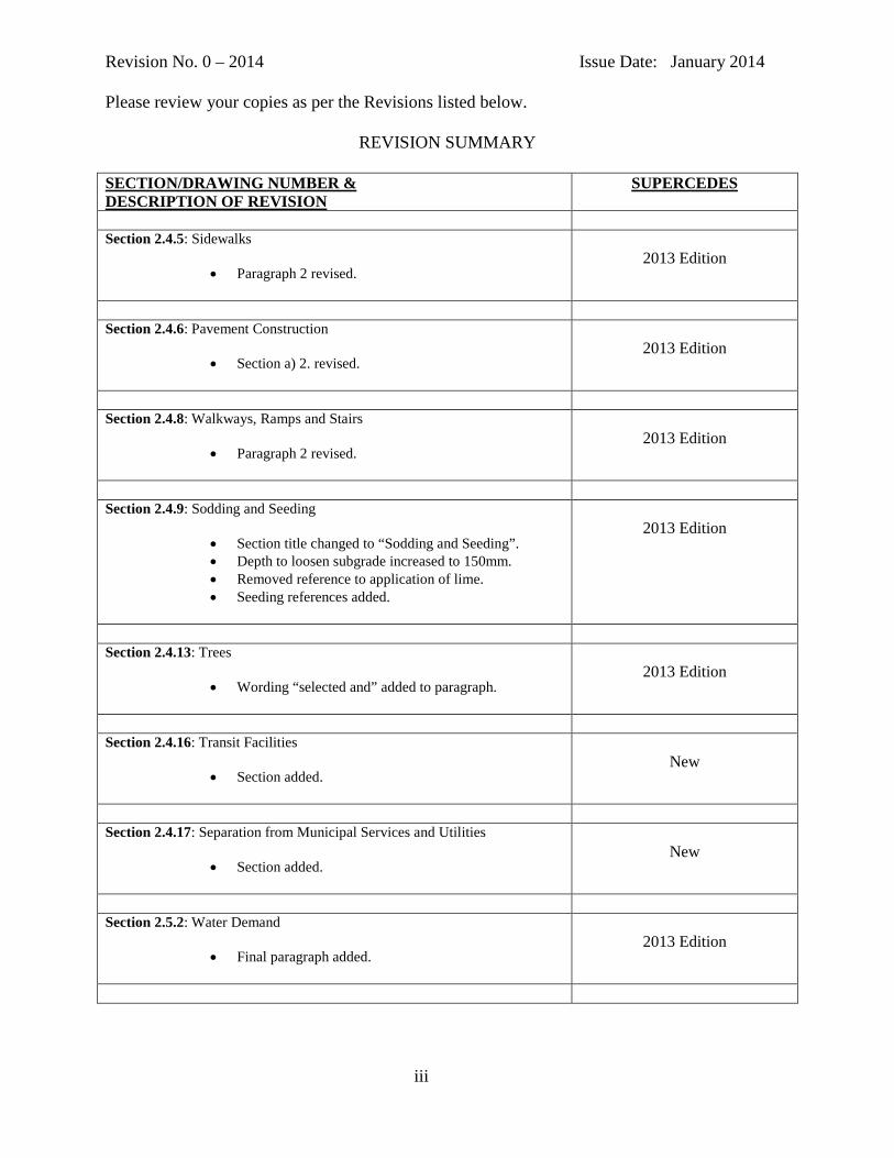
Section 2.4.5: Sidewalks
• Paragraph 2 revised.
2013 Edition
Section 2.4.6: Pavement Construction
• Section a) 2. revised.
2013 Edition
Section 2.4.8: Walkways, Ramps and Stairs
• Paragraph 2 revised.
2013 Edition
Section 2.4.9: Sodding and Seeding
• Section title changed to “Sodding and Seeding”. • Depth to loosen subgrade increased to 150mm. • Removed reference to application of lime. • Seeding references added.
2013 Edition
Section 2.4.13: Trees
• Wording “selected and” added to paragraph.
2013 Edition
Section 2.4.16: Transit Facilities
• Section added.
New
Section 2.4.17: Separation from Municipal Services and Utilities
• Section added.
New
Section 2.5.2: Water Demand
• Final paragraph added.
2013 Edition
iii

Revision No. 0 – 2014 Issue Date: January 2014 Please review your copies as per the Revisions listed below.
REVISION SUMMARY
SECTION/DRAWING NUMBER & DESCRIPTION OF REVISION
SUPERCEDES
Section 2.5.5: Private Fire Protection System
• Paragraph 1 and 2 revised.
2013 Edition
Section 2.5.9: System Layout
• Sections a) and b) revised.
2013 Edition
Section 4.1: Supervision of Construction Development Services
• Section e) revised.
2013 Edition
Section 4.2: Start of Construction
• Section b) revised.
2013 Edition
Section 5.2: Initial (Provisional) Acceptance
• “Provisional” added to section title. • Reference to “one year” removed. • Paragraph 3 added.
2013 Edition
Section 5.3: Final Acceptance
• Reference to “one year” removed.
2013 Edition
Section 5.4.3: Surface Works
• Paragraph 1 revised. • Section h) and k) revised. • Section l) added.
2013 Edition
iv

Revision No. 0 – 2014 Issue Date: January 2014 Please review your copies as per the Revisions listed below.
REVISION SUMMARY
SECTION/DRAWING NUMBER & DESCRIPTION OF REVISION
SUPERCEDES
M - DRAWINGS
M-104-1: Deciduous Tree Bare Root Planting Detail Typical Installation for 45mm Caliper Trees or Less.
• Revisions:
o Revised note “Caliper is measured at 300 mm from grade level. “ Note now reads, “Caliper is measured at 150 mm from soil grade level.”
o Revised note “Soil to be tamped and settled with water by probing with hose-end to eliminate air pockets.” And added “Approved soil to be tamped and settled with water by probing with hose-end to eliminate air pockets.”
o Revised asterisk note,”Parks Division Guidelines and Specifications” To “Parks Division Standards and Specifications.”
o Revised note, “Actual hole to be 300 mm wider than around the perimeter of the rootball.” By adding “min.” after rootball.
o Removed note, “Hole to be backfilled with soil that is native to the site, amend if required. Concurrently tamp and water to eliminate air pockets.”
o New note added, “All trees to be planted in a min. of 15mᶾ of approved soil. This can be comprised of resident soil, imported soil or a combination of both providing all soils meet topsoil specifications as outlined in section 02921.”
o Rodent guard and waterbag now shown at the base of the tree in the drawing with accompanying leader note.
o Addition of “solid” to leader note as follows, “2(38x38x2300) wood stakes secured into “solid” ground and placed on the north and south aspects of the tree wherever possible – min. 2000 mm long. Set tree stakes just inside tree pit as shown.”
M-104-1 – Revised Jan. 2012
v

Revision No. 0 – 2014 Issue Date: January 2014 Please review your copies as per the Revisions listed below.
REVISION SUMMARY
SECTION/DRAWING NUMBER & DESCRIPTION OF REVISION
SUPERCEDES
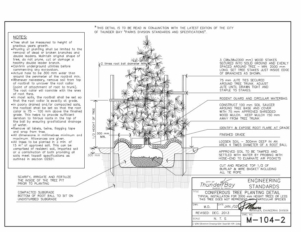
M-104-2: Coniferous Tree Planting Detail Typical Installation for 2000mm Height Trees or Less
• Revisions:
o Revised asterisk note,”Parks Division Guidelines and Specifications” To “Parks Division Standards and Specifications.”
o Revised note “Soil to be tamped and settled with water by probing with hose-end to eliminate air pockets.” And added “Approved soil to be tamped and settled with water by probing with hose-end to eliminate air pockets.”
o Revised note, “Actual hole to be 300 mm wider than around the perimeter of the rootball.” By adding “min.” after rootball.
o Removed note, “Wooden stakes MUST be installed prior to back-filling hole. Hammer stakes into solid footing.”
o Removed note, “Hole to be backfilled with soil that is native to the site, amend if required. Concurrently tamp and water to eliminate air pockets.”
o New note added, “All trees to be planted in a min. of 15mᶾ of approved soil. This can be comprised of resident soil, imported soil or a combination of both providing all soils meet topsoil specifications as outlined in section 02921.”
o Addition of “solid” to leader note as follows, “2(38x38x2300) wood stakes secured into “solid” ground and placed on the north and south aspects of the tree wherever possible – min. 2000 mm long. Set tree stakes just inside tree pit as shown.”
o Rodent guard and circular waterbag now shown at the base of the tree in the drawing with accompanying leader note.
M-104-2 – Revised Jan. 2012
vi

Revision No. 0 – 2014 Issue Date: January 2014 Please review your copies as per the Revisions listed below.
REVISION SUMMARY
SECTION/DRAWING NUMBER & DESCRIPTION OF REVISION
SUPERCEDES
M-104-3: Deciduous Tree Planting Detail Typical Installation for 75mm Caliper Trees or Less
• Revisions:
o Revised asterisk note,”Parks Division Guidelines and Specifications” To “Parks Division Standards and Specifications.”
o Revised note “Soil to be tamped and settled with water by probing with hose-end to eliminate air pockets.” And added “Approved soil to be tamped and settled with water by probing with hose-end to eliminate air pockets.”
o Revised note “Caliper is measured at 300 mm from grade level. “ Note now reads, “Caliper is measured at 150 mm from soil grade level.”
o Revised note, “Actual hole to be 300 mm wider than around the perimeter of the rootball.” By adding “min.” after rootball.
o Removed note, “Wooden stakes MUST be installed prior to back-filling hole. Hammer stakes into solid footing.”
o Removed note, “Hole to be backfilled with soil that is native to the site, amend if required.”
o Removed note, “Concurrently tamp and water to eliminate air pockets.”
o New note added, “All trees to be planted in a min. of 15mᶾ of approved soil. This can be comprised of resident soil, imported soil or a combination of both providing all soils meet topsoil specifications as outlined in section 02921.”
o Addition of “solid” to leader note as follows, “2(38x38x2300) wood stakes secured into “solid” ground and placed on the north and south aspects of the tree wherever possible – min. 2000 mm long. Set tree stakes just inside tree pit as shown.”
o Rodent guard and waterbag now shown at the base of the tree in the drawing with accompanying leader note.
M-104-3 – Revised Jan. 2012
vii

Revision No. 0 – 2014 Issue Date: January 2014 Please review your copies as per the Revisions listed below.
REVISION SUMMARY
SECTION/DRAWING NUMBER & DESCRIPTION OF REVISION
SUPERCEDES
M-104-4: Tree Protection Barriers
• Revisions: o All note text changed to capital lettering. o Revised Tree Protection Fencing sub-note from,
“Required when authorized by city forester” to “Required for all trees.”
o Revised Tree Trunk Protection sub-note from, “Required for all trees” to “Alternate protection method when work inside dripline is required. Requires city forester approval.”
o Revised note #4 by changing the word “guidelines” to “standards”.
o Removed “The city forester may require designated areas within the construction zone to have tree protection and separate them from construction activities.” From note #3 and revised note to, “Final layout of tree protection fencing to be field verified with city forester prior to construction.”
o Note #3 moved up to second note position, while second note is now note #3.
o Revised note by replacing “All trees within the proposed construction areas shall require..” with “Where approved, tree trunk protection shall consist of strapping or a double wrap of wood slat snow fencing, polyethylene drums or other suitable wood planks strapped to the tree trunk to completely protect the tree trunk from impact damage. The minimum size of strapping will be 25 x 150 x 2400 mm.”
M-104-4– Revised Jan. 2012
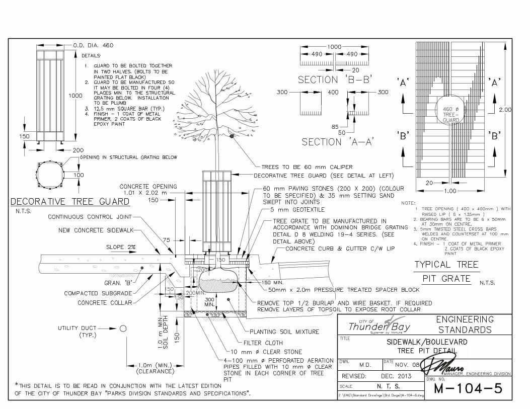
M-104-5: Sidewalk / Boulevard Tree Pit Detail
• Revisions: o Revised asterisk note,”Parks Division Guidelines and
Specifications” To “Parks Division Standards and Specifications.”
o Revised Decorative Tree Guard height dimension from “1300” to “1000”.
M-104-5– Revised Jan. 2012
viii
Revision No. 0 – 2014 Issue Date: January 2014 Please review your copies as per the Revisions listed below.
REVISION SUMMARY
SECTION/DRAWING NUMBER & DESCRIPTION OF REVISION
SUPERCEDES
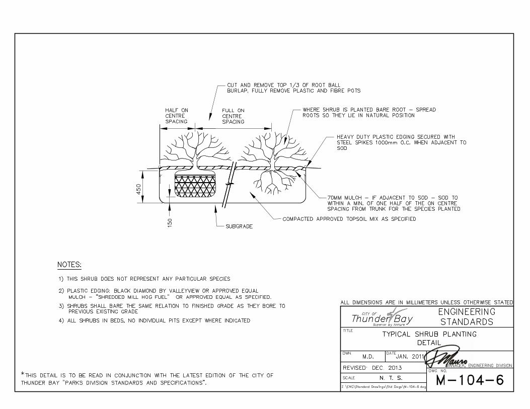
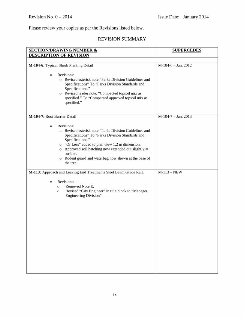
M-104-6: Typical Shrub Planting Detail
• Revisions: o Revised asterisk note,”Parks Division Guidelines and
Specifications” To “Parks Division Standards and Specifications.”
o Revised leader note, “Compacted topsoil mix as specified.” To “Compacted approved topsoil mix as specified.”
M-104-6 – Jan. 2012
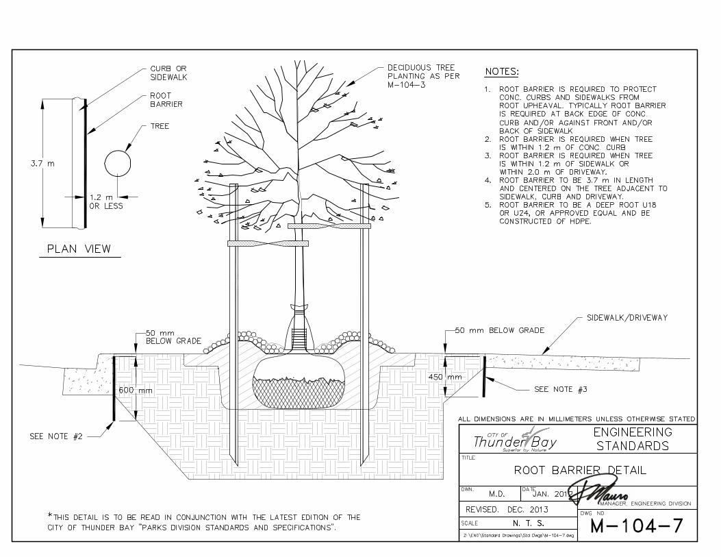
M-104-7: Root Barrier Detail
• Revisions: o Revised asterisk note,”Parks Division Guidelines and
Specifications” To “Parks Division Standards and Specifications.”
o “Or Less” added to plan view 1.2 m dimension. o Approved soil hatching now extended out slightly at
surface. o Rodent guard and waterbag now shown at the base of
the tree.
M-104-7 – Jan. 2013
M-113: Approach and Leaving End Treatments Steel Beam Guide Rail.
• Revisions: o Removed Note E. o Revised “City Engineer” in title block to “Manager,
Engineering Division”
M-113 – NEW
ix
Revision No. 0 – 2014 Issue Date: January 2014 Please review your copies as per the Revisions listed below.
REVISION SUMMARY
SECTION/DRAWING NUMBER & DESCRIPTION OF REVISION
SUPERCEDES
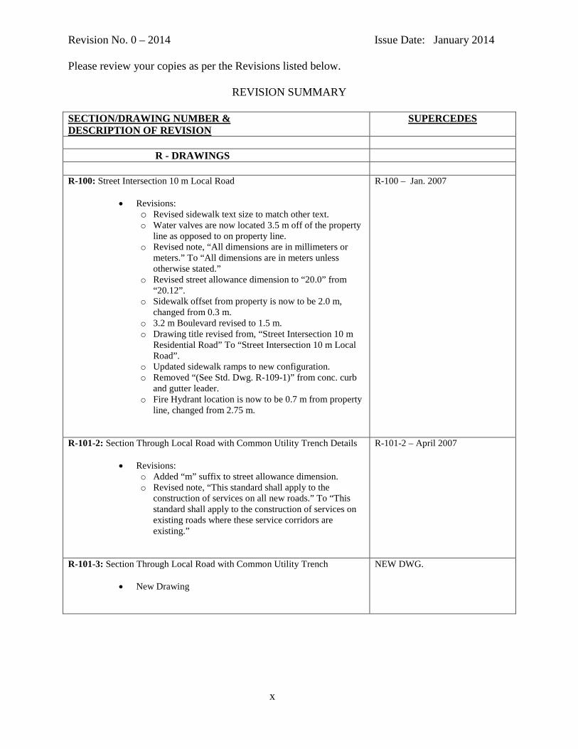
R - DRAWINGS
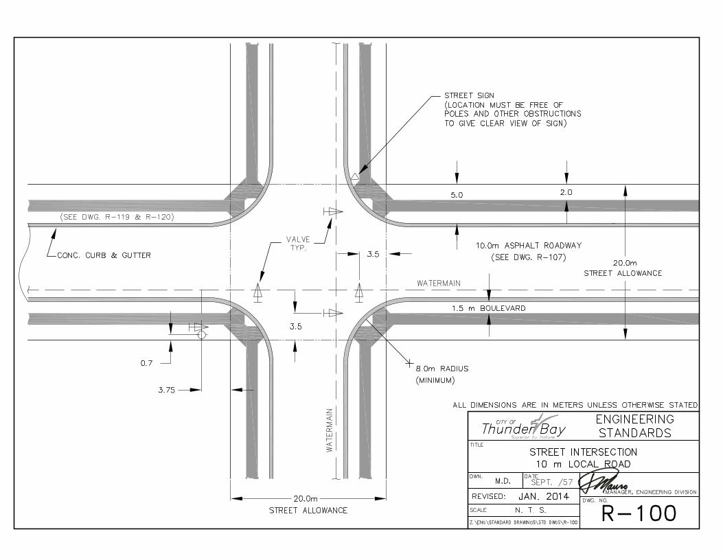
R-100: Street Intersection 10 m Local Road
• Revisions: o Revised sidewalk text size to match other text. o Water valves are now located 3.5 m off of the property
line as opposed to on property line. o Revised note, “All dimensions are in millimeters or
meters.” To “All dimensions are in meters unless otherwise stated.”
o Revised street allowance dimension to “20.0” from “20.12”.
o Sidewalk offset from property is now to be 2.0 m, changed from 0.3 m.
o 3.2 m Boulevard revised to 1.5 m. o Drawing title revised from, “Street Intersection 10 m
Residential Road” To “Street Intersection 10 m Local Road”.
o Updated sidewalk ramps to new configuration. o Removed “(See Std. Dwg. R-109-1)” from conc. curb
and gutter leader. o Fire Hydrant location is now to be 0.7 m from property
line, changed from 2.75 m.
R-100 – Jan. 2007
R-101-2: Section Through Local Road with Common Utility Trench Details
• Revisions: o Added “m” suffix to street allowance dimension. o Revised note, “This standard shall apply to the
construction of services on all new roads.” To “This standard shall apply to the construction of services on existing roads where these service corridors are existing.”
R-101-2 – April 2007
R-101-3: Section Through Local Road with Common Utility Trench
• New Drawing
NEW DWG.
x
Revision No. 0 – 2014 Issue Date: January 2014 Please review your copies as per the Revisions listed below.
REVISION SUMMARY
SECTION/DRAWING NUMBER & DESCRIPTION OF REVISION
SUPERCEDES
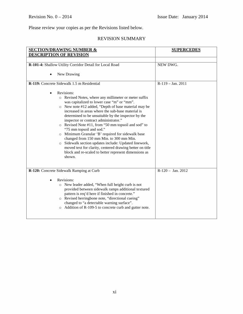
R-101-4: Shallow Utility Corridor Detail for Local Road
• New Drawing
NEW DWG.
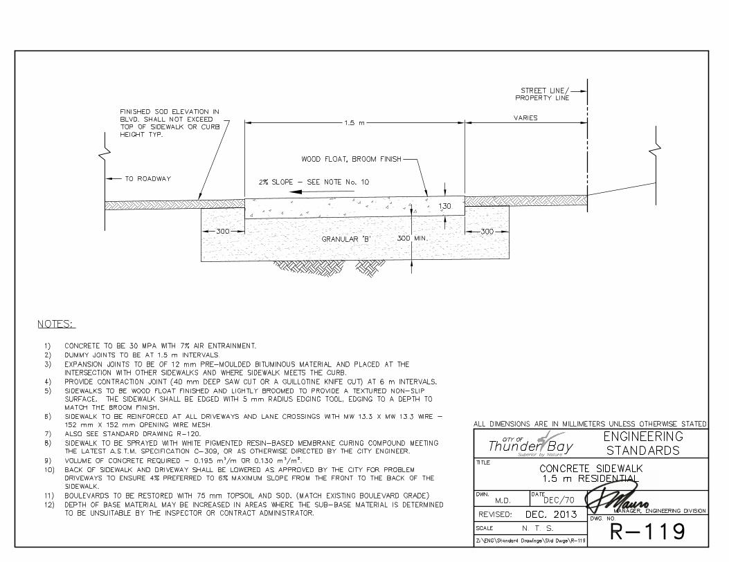
R-119: Concrete Sidewalk 1.5 m Residential
• Revisions: o Revised Notes, where any millimeter or meter suffix
was capitalized to lower case “m” or “mm”. o New note #12 added, “Depth of base material may be
increased in areas where the sub-base material is determined to be unsuitable by the inspector by the inspector or contract administrator.”
o Revised Note #11, from “50 mm topsoil and sod” to “75 mm topsoil and sod.”
o Minimum Granular ‘B’ required for sidewalk base changed from 150 mm Min. to 300 mm Min.
o Sidewalk section updates include: Updated linework, moved text for clarity, centered drawing better on title block and re-scaled to better represent dimensions as shown.
R-119 – Jan. 2011
R-120: Concrete Sidewalk Ramping at Curb
• Revisions: o New leader added, “When full height curb is not
provided between sidewalk ramps additional textured pattern is req’d here if finished in concrete.”
o Revised herringbone note, “directional cueing” changed to “a detectable warning surface”.
o Addition of R-109-5 to concrete curb and gutter note.
R-120 – Jan. 2012
xi
Revision No. 0 – 2014 Issue Date: January 2014 Please review your copies as per the Revisions listed below.
REVISION SUMMARY
SECTION/DRAWING NUMBER & DESCRIPTION OF REVISION
SUPERCEDES
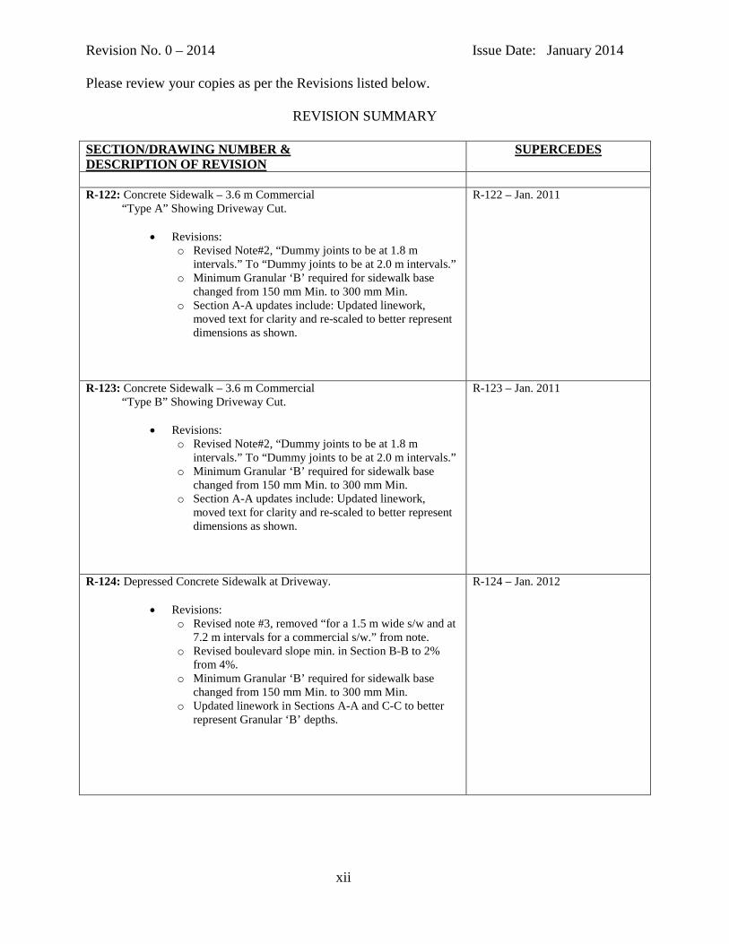
R-122: Concrete Sidewalk – 3.6 m Commercial “Type A” Showing Driveway Cut.
• Revisions: o Revised Note#2, “Dummy joints to be at 1.8 m
intervals.” To “Dummy joints to be at 2.0 m intervals.” o Minimum Granular ‘B’ required for sidewalk base
changed from 150 mm Min. to 300 mm Min. o Section A-A updates include: Updated linework,
moved text for clarity and re-scaled to better represent dimensions as shown.
R-122 – Jan. 2011
R-123: Concrete Sidewalk – 3.6 m Commercial “Type B” Showing Driveway Cut.
• Revisions: o Revised Note#2, “Dummy joints to be at 1.8 m
intervals.” To “Dummy joints to be at 2.0 m intervals.” o Minimum Granular ‘B’ required for sidewalk base
changed from 150 mm Min. to 300 mm Min. o Section A-A updates include: Updated linework,
moved text for clarity and re-scaled to better represent dimensions as shown.
R-123 – Jan. 2011
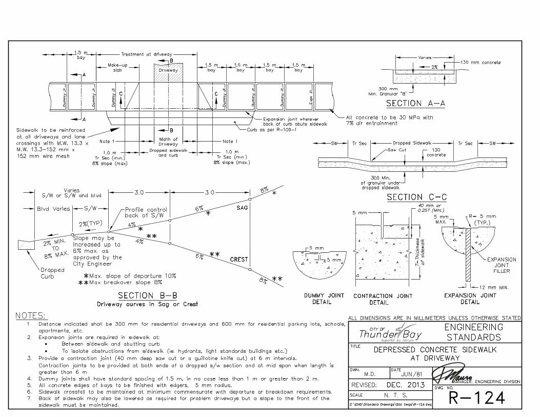
R-124: Depressed Concrete Sidewalk at Driveway.
• Revisions: o Revised note #3, removed “for a 1.5 m wide s/w and at
7.2 m intervals for a commercial s/w.” from note. o Revised boulevard slope min. in Section B-B to 2%
from 4%. o Minimum Granular ‘B’ required for sidewalk base
changed from 150 mm Min. to 300 mm Min. o Updated linework in Sections A-A and C-C to better
represent Granular ‘B’ depths.
R-124 – Jan. 2012
xii

Revision No. 0 – 2014 Issue Date: January 2014 Please review your copies as per the Revisions listed below.
REVISION SUMMARY
SECTION/DRAWING NUMBER & DESCRIPTION OF REVISION
SUPERCEDES
R-127: Driveway Control Layout for Other Uses.
• Revisions: o New note added, “See std. dwg. No. R-111 for barrier
curb details.” o “Optional D/W Curbs” revised to “Mandatory D/W
Curbs”
R-127 – Jan. 2013
S - DRAWINGS S-107: Catch Basin (Precast Barrel Type).
• Revisions: o Section B-B, revised the shallow type catch basin
dimension from “610” to “815”.
S-107 – Jan. 2013
W - DRAWINGS
W-101: Installation of Fire Hydrant with Gate Valve.
• Revisions: o Added new note #11, “Like materials to be used for
watermain tie in. Where existing watermain is metallic use ductile iron pipe for the tie in.” and accompanying label.
W-101 – Jan. 2011
W-103: Installation of Gate Valve.
• Revisions: o Added watermain note, “When installing on existing
watermains use like pipe material. If metallic use ductile iron pipe.”
W-103 – Jan. 2011
xiii

Revision No. 0 – 2014 Issue Date: January 2014 Please review your copies as per the Revisions listed below.
REVISION SUMMARY
SECTION/DRAWING NUMBER & DESCRIPTION OF REVISION
SUPERCEDES
W-104-1: Water Connection Installation & Sizing & Thaw/Tracer Cable Installation for P.V.C. watermain.
• Revisions: o Revised note, “Corporation Stops – Mueller No. A220
or H-15009 (20 mm and 25 mm), B-25008 (40 mm and 50 mm), Cambridge 301NL and Ford FB600 or FB1000. Tap into watermain by approved method.” By changing “Mueller No. A220” to “Mueller B-25000”.
W-104-1 – Jan. 2011
xiv

I N D E X
CITY OF THUNDER BAY ENGINEERING AND DEVELOPMENT STANDARDS
SECTION PAGE NUMBER REVISION SUMMARY i to xiv INDEX 1 to 5 2014 LIST OF STANDARD DRAWINGS 6 to 13 2014 LIST OF REFERENCE DRAWINGS 14 DEVELOPMENT PROCESS FIGURE 1 15 SECTION 1.0 - INTRODUCTION
Section 1.1 Purpose 1-1 Section 1.2 Process 1-1 Section 1.3 Exemptions 1-1 Section 1.4 Design and Construction of Services 1-1 Section 1.5 Operation of Existing Services 1-2 Section 1.6 Environmental Considerations 1-2 Section 1.7 General Conditions of Contract 1-2 Section 1.8 Construction of Services on City Lands 1-3
SECTION 2.0 - DESIGN STANDARDS
Section 2.1 Approvals 2-1 Section 2.1.1 Drinking Water Approvals – City of Thunder Bay 2-1 Section 2.1.2 Sanitary and Storm Approvals – Ministry of Environment 2-1 Section 2.2 Sanitary Sewers 2-1 Section 2.2.1 Area 2-1 to 2-2 Section 2.2.2 Design Flow 2-2 Section 2.2.3 Population Densities 2-2 Section 2.2.4 Peak Factor 2-2 to 2-3 Section 2.2.5 Roughness Co-efficient 2-3 Section 2.2.6 Velocity 2-3 Section 2.2.7 Grades 2-3 Section 2.2.8 Minimum Size and Strength of Sanitary Sewer 2-4 Section 2.2.9 Depth 2-4 Section 2.2.10 Clearance Between Pipes 2-4 Section 2.2.11 Manholes 2-4 to 2-5 Section 2.2.12 Locations 2-5 Section 2.2.13 Building Connections (Sanitary Sewer) 2-5 Section 2.2.14 Bedding Pipe 2-5 Section 2.2.15 Construction 2-6 Section 2.2.16 Television Inspection 2-6 Section 2.2.17 Storm Sewers Outfall into Lake Superior and the 2-6 Neebing McIntyre Floodway Section 2.3 Storm Water Management 2-6 Section 2.3.1 Objectives 2-6 to 2-9 Section 2.3.2 Minor/Major Systems 2-9 Section 2.3.3 Requirements 2-9 to 2-10 Section 2.3.4 Design Brief 2-10 to 2-11
Index – Page 1

SECTION PAGE NUMBER
Section 2.3.5 Lot Grading Plan 2-11 to 2-14 Section 2.3.6 Lot Grading 2-14 Section 2.3.7 Storm Sewer Location 2-14 Section 2.3.8 Pipe Sizes and Strength 2-14 to 2-15 Section 2.3.9 Manholes 2-15 Section 2.3.10 Building Connections (Storm Sewer) 2-15 Section 2.3.11 Rainfall Intensity 2-16 Section 2.3.12 Calculating Runoff Flows 2-16 Section 2.3.13 Runoff Co-efficients 2-17 Section 2.3.14 Roughness Co-efficient 2-17 Section 2.3.15 Velocity 2-17 to 2-18 Section 2.3.16 Catch Basins 2-18 to 2-19 Section 2.3.17 Culverts 2-19 to 2-20 Section 2.3.18 Television Inspection 2-20 Section 2.3.19 Erosion Protection and Sediment Control 2-20 Section 2.3.20 Catch Basin Retrofit - Policy 2-20 to 2-21 Section 2.4 Roadways, Curbs, Gutters Sidewalks, and Parking Lots 2-21 Section 2.4.1 General Construction 2-21 Section 2.4.2 Radii 2-22 Section 2.4.3 Road Grades 2-22 Section 2.4.4 Concrete 2-22 Section 2.4.5 Sidewalks 2-22 Section 2.4.6 Pavement Construction 2-23 to 2-24 Section 2.4.7 Boulevards 2-24 Section 2.4.8 Walkways, Ramps and Stairs 2-25 Section 2.4.9 Sodding and Seeding 2-25 to 2-26 Section 2.4.10 Specifications for Drivable Gravel Roads for New 2-26 to 2-28
Subdivisions Section 2.4.11 Parking Lots 2-28 Section 2.4.12 Easements 2-28 Section 2.4.13 Section 2.4.14
Trees Bike Lanes
2-29 2-29
Section 2.4.15 Signs 2-29 Section 2.4.16 Transit Facilities 2-29 Section 2.4.17 Separation from Municipal Services and Utilities 2-29 to2-30 Section 2.5 Water Systems 2-30 Section 2.5.1 Cathodic Protection 2-30 Section 2.5.2 Water Demand 2-30 Section 2.5.3 Peaking Factors 2-30 to 2-31 Section 2.5.4 Fire Demands 2-31 to 2-32 Section 2.5.5 Private Fire Protection Systems 2-33 to 2-34 Section 2.5.6 System Pressures 2-35 Section 2.5.7 Friction Factors 2-35 Section 2.5.8 Minimum Size of Watermains 2-36 Section 2.5.9 System Layout 2-36 to 2-39
SECTION 3.0 - PLANS AND DRAWINGS Section 3.1 Preliminary Draft 3-1 Section 3.2 Final Draft 3-1
Index – Page 2

SECTION PAGE NUMBER
Section 3.3 Preliminary Construction Drawings 3-1 to 3-2 Section 3.4 Construction Drawings 3-2 to 3-3 Section 3.5 As-constructed Drawings 3-3 to 3-4 Section 3.6 Preliminary As-constructed Prints 3-4 Section 3.7 Service Connection Drawings 3-4 Section 3.8 As-constructed Originals 3-5
SECTION 4.0 - CONSTRUCTION STANDARDS
Section 4.1 Supervision of Construction of Development Services 4-1 to 4-2 Section 4.2 Start of Construction 4-2 Section 4.3 Section 4.4 Section 4.5
Fire Hydrants out of Service Road Closures Sidewalk Closures
4-3 4-3 4-3
SECTION 5.0 - ACCEPTANCE OF DEVELOPMENT
Section 5.1 Basis of Acceptance 5-1 Section 5.2 Initial Provisional Acceptance 5-1 Section 5.3 Final Acceptance 5-2 Section 5.4 Acceptance of Sections of the Development 5-2 Section 5.4.1 Underground Services 5-2 Section 5.4.2 Building Connections 5-3 Section 5.4.3 Surface Works 5-3 to 5-4 Section 5.4.4 Roadway Illumination 5-5 Section 5.5 Policy for Acceptance of Concrete Work in Developments 5-5 Section 5.5.1 Initial Acceptance 5-5 Section 5.5.2 Final Acceptance 5-6
SECTION 6.0 - ROADWAY ILLUMINATION SYSTEMS
Section 6.1 Design Specifications 6-1 Section 6.1.1 Illumination 6-1 Section 6.1.2 Electrical 6-1 Section 6.1.3 Road and Pedestrian Conflict Area 6-1 Section 6.2 Construction Specifications 6-2 Section 6.2.1 Qualifications 6-2 Section 6.2.2 Approval 6-2 Section 6.2.3 Buried Wire 6-2 to 6-3 Section 6.2.4 Wood Poles 6-3 Section 6.2.5 Steel Poles 6-3 Section 6.2.6 Reinforced Concrete Base 6-4 Section 6.2.7 Support Bracket 6-4 Section 6.2.8 Luminaire 6-4 Section 6.2.9 Ground Wire 6-4 Section 6.2.10 Grounding 6-4 Section 6.2.11 Relay / Photocell Controls 6-5 Section 6.2.12 Service Disconnect 6-5 Section 6.2.13 Junction Box 6-5 Section 6.2.14 Fusing 6-5 Section 6.2.15 Wire Connections 6-5 Section 6.2.16 Testing 6-6
Index – Page 3

SECTION PAGE NUMBER
SECTION 7.0 – TRANSPORTATION
Section 7.1 Traffic Impact Study Guidelines 7-1 Section 7.1.1 Project Description 7-1 Section 7.1.2 Study Area 7-1 Section 7.1.3 Background Conditions 7-1 Section 7.1.4 Design Hours 7-2 Section 7.1.5 Horizon Year Traffic Scenarios 7-2 Section 7.1.6 Background Traffic 7-2 to 7-3 Section 7.1.7 Site Traffic Generation 7-3 Section 7.1.8 Site Traffic Distribution 7-3 Section 7.1.9 Site Traffic Assignment 7-3 Section 7.1.10 Development Staging 7-3 Section 7.1.11 Graphics 7-3 to 7-4 Section 7.1.12 Capacity Analysis 7-4 to 7-5 Section 7.1.13 Pedestrian and Cyclists 7-5 Section 7.1.14 Transportation System Modifications 7-5 Section 7.1.15 Other Items 7-6 Section 7.1.16 Table of Contents 7-6 to 7-7 Section 7.2 Road Classification and Design Guidelines 7-7 Section 7.2.1 Transportation Analysis – New Development 7-7
SECTION 8.0 - CATHODIC PROTECTION OF WATER
DISTRIBUTION PIPING Section 8.1 Design Specifications 8-1 Section 8.1.1 New Ductile Iron Watermains 8-1 Section 8.1.1.1 Zinc Anode Requirements 8-1 to 8-2 Section 8.1.1.2 Magnesium Anode Requirements 8-3 to 8-4 Section 8.1.1.3 Test Stations 8-4 Section 8.1.2 New PVC Watermains 8-4 Section 8.1.2.1 Valves & Fittings 8-4 Section 8.1.2.2 Hydrants 8-4 Section 8.1.2.3 Copper Services 8-5 Section 8.1.3 Existing Watermains 8-5 Section 8.1.3.1 Ductile and Grey Cast Iron Watermains 8-5 Section 8.1.3.2 PVC Watermains 8-5
SECTION 9.0 - SEPTIC FIELDS
Section 9.1 Introduction 9-1 Section 9.2 Development Requirements for On-Site Sub-Surface
Sewage Treatment Facilities 9-1
Section 9.2.1 Lands Developed without Subdivision or Development Agreement
9-1 to 9-3
Section 9.2.2 Lands Developed by Subdivision or Development Agreement 9-3 to 9-5
Index – Page 4

SECTION PAGE NUMBER
SECTION 10.0 – CONSTRUCTION SPECIFICATIONS
Section 10.1 General 10-1 Section 10.2 Writing Style 10-1 to 10-4 Section 10.3 Pitfalls 10-4 to 10-10 Section 10.4 Master Project Specifications 10-10 to 10-11
Index – Page 5

2013 LIST OF STANDARD DRAWINGS DESCRIPTION DRAWING NUMBER Reinforced Concrete Base (Type "A") for Traffic Sign Pole E-100 Reinforced Concrete Base (Type "B") for Traffic Light Pole E-101 Reinforced Concrete Base (Type "C") for Street and Traffic Light Pole E-102 Reinforced Concrete Base (Type "D1") for Street and Traffic Light Pole E-103-1 Reinforced Concrete Base (Type “D2”) for Steel Street Light Pole E-103-2 Reinforced Concrete Base (Type "E") for Street and Traffic Light Pole E-104 Reinforced Concrete Base (Type 'G') for Sectional Steel Pole E-106
Reinforced Concrete Base (Type 'H') for Street and Traffic Light Poles in Rock Conditions E-107 Reinforced Concrete Base Installation Behind Concrete Sidewalk E-108 Concrete Base for Traffic Control Cabinet E-109 Electrical Manhole (Precast Barrel Type) E-110 Wood Street Light Pole Installation E-111 Information Required on All Sewer and Water Connections M-101 Chain Link Security Fence M-103-1 Chain Link Security Gates M-103-2 Deciduous Tree Bare Root Planting Detail M-104-1
Index – Page 6

2013 LIST OF STANDARD DRAWINGS DESCRIPTION DRAWING NUMBER Coniferous Tree Planting Detail M-104-2 Deciduous Tree Planting Detail
M-104-3
Tree Protection Barriers
M-104-4
Tree Root Protection M-104-4.1 Sidewalk/Boulevard Tree Pit Detail M-104-5 Typical Shrub Planting Detail M-104-6 Root Barrier Detail M-104-7 Concrete Retaining Wall with Footing M-105-1 Concrete Retaining Wall Attached To Concrete Sidewalk M-105-2 Concrete Retaining Wall with Footing (For Elevated Sidewalk) M-105-3 Parking Meter Installation in Concrete And Original Ground M-106 Rainfall Intensity - Duration Curves M-108 Standard Drawing Symbols M-110 Typical Street & Traffic Sign Mounting Details M-112 Approach & Leaving End Treatments Steel Beam Guide Rail M-113 Pipe Bollard M-114 Inverted Bicycle Rack Details & Sections M-115-1 Inverted Bicycle Rack Multiple Rack Layout M-115-2 Post and Ring Bike Rack Details & Sections M-115-3
Street Intersection - 10 m Residential Road R-100
Index – Page 7

2013 LIST OF STANDARD DRAWINGS DESCRIPTION DRAWING NUMBER Section through Local Road R-101-1 Section through Local Road with Common Utility Trench Details R-101-2 Section Through Local Road with Shallow Utility Corridor R-101-3 Shallow Utility Corridor Detail for Local Road R-101-4 Section through Collector Road R-102 Section through Arterial Road R-103 Rural Road Section R-104-1 Rural Road Cul-de-sac Layouts R-104-2 Temporary Turning Basin for Terminated Rural Road Extension R-105 Urban Cul-de-sac Layouts R-106
Asphalt Roadway with Sub-drain Pipe Details R-107 Patching for Roadway Cuts R-108 One Piece Concrete Curb and Gutter (Sloped Gutter) R-109-1 One Piece Concrete Curb and Gutter (Flat Gutter) R-109-2 Curb Restoration at New Cut in Existing Curb & Gutter R-109-3 Existing Curb and/or Gutter Replacement R-109-4 Concrete Mountable Curb with Standard Gutter R-109-5 Two Piece Concrete Curb and Gutter R-110 Concrete Curb (only) R-111
Index – Page 8

2013 LIST OF STANDARD DRAWINGS DESCRIPTION DRAWING NUMBER Termination of Curb and Gutter R-112
90° Gutter Outlet for Concrete Curb and Gutter R-113
45° Gutter Outlet for Concrete Curb and Gutter R-114 Concrete Curb and Gutter Around Fixtures R-115
Asphalt Curb and Gutter and Asphalt Gutter R-116
90° Gutter Outlet for Asphalt Curb and Gutter R-117
45° Gutter Outlet for Asphalt Curb and Gutter R-118 Concrete Sidewalk - 1.5 m Residential R-119 Concrete Sidewalk Ramping at Curb R-120 Concrete Sidewalk - 1.5 m Residential Curb Type Showing Driveway Cut R-121 Concrete Sidewalk - 3.6 m Commercial "Type A" Showing Driveway Cut R-122 Concrete Sidewalk - 3.6 m Commercial "Type B" Showing Driveway Cut R-123 Depressed Concrete Sidewalk at Driveway R-124
Entrance Control Layout for Residential Sites R-125 Entrance Control Layout For Commercial/Industrial Sites R-127 Road Classification and Design Guidelines for New Residential Development R-128
Precast Slab Replacement for Hollow Sidewalks R-129
Index – Page 9

2013 LIST OF STANDARD DRAWINGS DESCRIPTION DRAWING NUMBER Left Turn Restricted Entrance R-130 Sharrows With Parking and No Parking R-131-1 Dedicated Bike Lane With Parking and Without Parking R-131-2 Dedicated Bike Lane to Sharrow Through Intersection R-131-3 Bicycle and Sharrow Symbols R-131-4
Bedding for Sanitary and Storm Sewer Pipe S-100 House Sanitary Sewer Connection - Common Type S-102 Weeping Tile Connection to Storm Sewer S-103-1 Alternate Weeping Tile Connection to Storm Sewer S-103-2 Catch Basins (For Curb Type Sidewalk Installations) S-105 Catch Basin with Sloped Top (For Ditch Installation) S-106-1 Grate for Catch Basin with Sloped Top S-106-2 Catch Basin (Precast Barrel Type) S-107 Catch Basin Inlet (For Ditch Installation) S-108 Catch Basin Inlet (For Gutter Installation) S-109 Manhole for 1050 mm to 1350 mm Diameter Pipe - May have Cast-in-Place or Precast Base S-111 Manhole for 900 mm Diameter Pipe and Smaller - May have Cast-in-Place or Precast Base S-112
Index – Page 10

2013 LIST OF STANDARD DRAWINGS DESCRIPTION DRAWING NUMBER Precast Manhole for 750 mm Diameter Pipe and Smaller S-113 Precast Manhole for 900 mm Diameter Pipe and Smaller S-114 Precast Manhole for 1200 mm Diameter Pipe and Smaller S-115 Bedding for Watermains W-100 Installation of Fire Hydrant with Gate Valve W-101 Installation of Gate Valve W-103 Water Connection Installation and Sizing and Thaw/Tracer Cable Installation for P.V.C. Watermain W-104-1 Water Connection Installation and Sizing W-104-2 Water Connection Installation and Sizing W-104-3 Water Connection Installation and Sizing W-104-4 Typical Residential Meter and Valving Arrangement W-104-5 Typical Water Connection Fort William First Nation Lands W-104-6 Meter/Bypass/Valving Arrangement (Meters Exceeding 25 mm) W-104-7 Anchorage of Watermain Tees & Crosses W-108-1 Anchorage of Watermain at Tees & Crosses for P.V.C. Pipe W-108-2 Anchorage of Watermain Bends W-109 Method of Determining Sizes of Thrust Blocks W-110 Securing Fire Hydrant and Valve to Watermain (Mechanical Joint Pipe) W-111
Index – Page 11

2013 LIST OF STANDARD DRAWINGS DESCRIPTION DRAWING NUMBER Securing Hydrant Valve to Watermain (Mechanical Joint Pipe) W-112 Securing Watermain Tees and 90° Bends (Mechanical Joint Pipe) W-113 Lowering and Securing Required at New or Existing Watermain Crossing of New or Existing Sanitary Sewer W-114 Lowering and Securing of New or Existing Watermain Crossing New or Existing Culvert, Storm Sewer or Ditch W-115 Watermain Retainer Chart W-116 Disinfecting Watermains W-117 Allowable Leakage for Watermains W-118 Precast Concrete Valve Chamber for 400 mm to 600 mm Diameter Watermains W-119
Reinforced Concrete Water Meter Chamber W-120-1
General Arrangement - Water Meter Chamber W-120-2 Watermain Crossing Sewer Main with less than 500 mm Vertical Separation W-121 Sanitary Sewer and Watermain Installation in Common Earth Trench W-122 Sanitary Sewer and Watermain Installation in Common Rock Trench W-123 Protection of Existing Cast Iron Watermain Over New Sanitary or Storm Sewer W-124
Index – Page 12
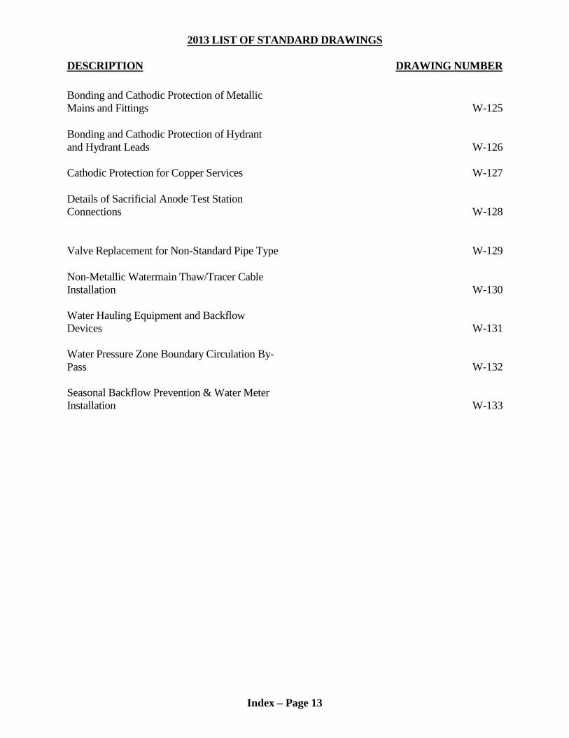
2013 LIST OF STANDARD DRAWINGS DESCRIPTION DRAWING NUMBER Bonding and Cathodic Protection of Metallic Mains and Fittings W-125 Bonding and Cathodic Protection of Hydrant and Hydrant Leads W-126 Cathodic Protection for Copper Services W-127 Details of Sacrificial Anode Test Station Connections W-128
Valve Replacement for Non-Standard Pipe Type W-129 Non-Metallic Watermain Thaw/Tracer Cable Installation W-130 Water Hauling Equipment and Backflow Devices W-131 Water Pressure Zone Boundary Circulation By-Pass W-132 Seasonal Backflow Prevention & Water Meter Installation W-133
Index – Page 13

2013 LIST OF REFERENCE DRAWINGS DESCRIPTION DRAWING NUMBER 1200mm Nom. I.D. Reinforced Precast Concrete Flat Manhole Cap
67 – 6358B
Precast Catch Basin Components 73 - 6992B 2100 mm Nom. I.D. to 1200 mm Nom. I.D. Reinforcing Precast Concrete Reducing Cap and 2100 mm Nom. I.D. Reinforced Precast Concrete Flat Cap
83 - 8310B
1650 mm Nom. I.D. to 1200 mm Nom. I.D. Reinforced Precast Concrete Reducing Cap And 1650 mm Nom. I.D. Reinforced Precast Concrete Flat Cap
86 - 8621B
City of Thunder Bay Standard Manhole Frame and Cover
09 - 0395B
City of Thunder Bay Short Manhole Frame 09 – 0400B Standard Catch Basin Frame And Grate Assembly
13 – 0569B
Index – Page 14

DEVELOPMENT PROCESS FIGURE I Planning Department ↓ Drawings to Roads and Transit Draft Plan to Engineering for Comments ∗ Divisions for Comments ↓ Draft Agreement to Engineering for Comments ∗ ↓ Agreement to City Solicitor Agreement Signed for Comments ↓ Preliminary Construction Drawings Submitted ∗ ↓ Comments and Required Changes on Drawing sent to Developer’s Engineer ↓ Final Construction Drawings Submitted for Approval ∗
Application sent to M O E ↓ for Certificate of Approval Consultant Hired to Represent the City
during Construction ↓ Liability Insurance and Performance Guarantees Submitted ↓ Insurance and Performance Guarantees Subdivision Agreement Released by City Clerk Reviewed and Revised as Required
Certificate of Approval for ↓ Works from M O E Received Pre-construction Meeting held with City, Developer, ∗
and City’s Consultant Present ↓
Written Approval given by City Engineer to Proceed ∗ with Work ↓ Construction Starts ↓ Consultant Reports to City Engineer on a Weekly Basis ∗ during Installation of Municipal Services
Periodic Site Inspections ∗ ↓ by City Engineering Installation of Underground Services and
Division during Course of Road Base Complete Construction ↓
Construction of Buildings on Lots Starts ↓ Construction of Surface Works is Completed ↓ Request for Initial Acceptance of Services ∗ by Developer ↓
Inspection of Completed Services by City ∗ ↓ Deficiency List complied and sent to Developer ↓ All Deficiencies Repaired by Developer ↓ One Year Maintenance Guarantee to ∗ City Engineering Division ↓ Initial Acceptance Certificate Issued to Developer by City Engineer ↓ Re-inspection of Municipal Services by City at the ∗ end of One Year Maintenance Period ↓ Any Deficiencies are Repaired by Developer ↓ All “As-Constructed” Information submitted ∗ to City Engineering Division ↓ Certificate of Final Acceptance issued by City Engineer ∗ ↓ City Assumes Responsibility to Maintain Public Municipal Services
Index – Page 15

SECTION 2.0 – DESIGN STANDARDS
2.0 DESIGN STANDARDS
Note: Additional material specifications and construction methods related to Section 2.0 Design Standards are defined in the specifications located in Section 10.4 “Master Project Specifications” under the section headings titled “Products” and “Execution”.
2.1 APPROVALS
2.1.1 Drinking Water Approvals – City of Thunder Bay
The City of Thunder Bay reviews and approves Drinking Water applications under the authority of Drinking Water Works Permit Number 024-201. The Design Engineer shall prepare the Ministry of the Environment application forms for approval of the water system and shall submit them along with three (3) sets of the plans and system design calculations to the Engineering Division. The City will carry out a full technical review of the application to ensure that the design is in accordance with City Engineering Standards and the M.O.E.’s “Watermain Design Criteria for Future Alterations Authorized Under a Drinking Water Works Permit (March 2009).” At the conclusion of the review, the reviewing engineer would recommend to the Manager – Engineering Division, or his designate, that a “Form 1 – Record of Watermains Authorized as a Future Alteration” be signed. No construction will be allowed to start prior to the receipt of a signed and verified Form 1. The Design Engineer should allow for a minimum two (2) week turn-around time for the technical review and approval by the City and the issuance of a signed Form 1.
2.1.2 Sanitary and Storm Sewer Approvals – Ministry of the Environment
The Design Engineer shall prepare the Ministry of the Environment application forms for approval of the sewer system(s) and shall submit them along with three (3) sets of the plans and system design calculations to the Engineering Division. The City will carry out a full technical review of the application to ensure that the works are in accordance with published M.O.E. guidelines and City Engineering Standards. At the conclusion of the review, the City would recommend to the Ministry’s Approvals Branch that a Certificate of Approval be issued. The Ministry of the Environment’s approval must be received before the City will allow construction to start. The Design Engineer should allow for a minimum four (4) week turn-around time for the technical review by the City and issuance of the approval certificate by the Ministry of the Environment.
2.2 SANITARY SEWERS
2.2.1 Area
Sanitary sewers shall have enough capacity to service the total area which is likely to be drained by the sewer including areas beyond the boundaries of the area to be
Page 2-1

SECTION 2.0 – DESIGN STANDARDS
developed. Information regarding the area to be drained may be obtained from the Engineering Division. Sewers are to be terminated at the Development boundaries when outside drainage areas are considered in the design.
2.2.2 Design Flow
All sanitary sewers shall have the capacity to carry the design flow determined as follows:
DESIGN FLOW FOR SANITARY SEWERS
Land Use Allowance for Average Groundwater Sewage Flow Infiltration
Residential 400 L/cap/day 0.260 L/ha/sec Existing Industrial 2.10L/ha/sec Includes Infiltration and Peaking New Industrial 1.75L/ha/sec Includes Infiltration and Peaking Existing Commercial 2.25L/ha/sec Includes Infiltration and Peaking New Commercial 1.80L/ha/sec Includes Infiltration and Peaking
ALLOWABLE INFILTRATION/EXFILTRATION
The allowable infiltration/exfiltration for sewer pipe shall not exceed 0.075 litres per millimeter of pipe diameter per 100 metres of sewer pipe. Infiltration/exfiltration shall be measured in accordance with O.P.S.S. 410.
2.2.3 Population Densities
When more accurate information is not available, the following values shall be used for population:
Single Family Residential 37 persons/ha Semi-Detached Residential 75 persons/ha Row Housing 125 persons/ha Low Rise Apartment Developments 175 persons/ha High Rise Apartment Developments 2,275 persons/ha Commercial Areas 125 persons/ha Light Industrial Areas 37-125 persons/ha
2.2.4 Peak Factor
The ratio of peak flow to average flow m is determined by the following formula: m = 1 + [ 14 / (4 + P 0.5) ]
Page 2-2

SECTION 2.0 – DESIGN STANDARDS
P = tributary population in thousands
2.2.5 Roughness Co-Efficient
When capacities of pipe are calculated using the Manning Formula the roughness co-efficient "n" shall not be less than 0.013 for all smooth walled pipe and 0.025 for corrugated metal pipe.
2.2.6 Velocity
All sewers shall be designed and constructed to give, when flowing full, a minimum velocity of 0.60 m/s and a maximum velocity of 3.0 m/s unless otherwise authorized by the Engineering Division. All sewers with slopes such that flow velocities will approach “critical velocity” shall be designed to reduce turbulence. All sewers shall be designed and constructed so that surcharging above the pipe obvert from backwater conditions does not occur. In the event the surcharging under backwater conditions is deemed minor in the opinion of the Engineering Division and mitigating measures are not required to eliminate such surcharging, the following conditions shall be complied with: a) The level of surcharging in the sewer shall be plotted on the profile view of the
sewer. b) The surcharging shall not extend into any lateral connection past the property line
of any land served by the sewer. 2.2.7 Grades
The minimum grade is 0.30% while the preferable grade which should be provided whenever possible is 0.50%. The first sewer length between manholes starting from a dead-end shall have at least a 0.50% grade. Grades of less than 0.30% shall be approved by the Engineering Division prior to starting of construction drawings.
Page 2-3

SECTION 2.0 – DESIGN STANDARDS
2.2.8 Minimum Size and Strength of Sanitary Sewer
The minimum size of all sanitary sewer pipe shall be 250 mm diameter. Pipe sizes up to and including 375 mm diameter shall be P.V.C. sewer pipe having a minimum S.D.R. of 35 conforming to O.P.S.S. 1841. Pipe sizes larger than 375 mm diameter shall be reinforced concrete pipe conforming to CSA A257.2-M1982 strength classification - 100-D. (formerly Class IV).
2.2.9 Depth
The minimum depth of cover on sanitary sewers shall be 2.50 m (preferably 2.75 m). If this depth of cover cannot be obtained then the elevation of the proposed basement floor for each building which will be serviced by this sewer shall be raised. When this situation is encountered the basement floor elevations shall be approved by the Engineering Division and shown on the plans.
2.2.10 Clearance Between Pipes
A minimum of 75 mm clearance is required between outside pipe barrels at all pipe crossings.
2.2.11 Manholes
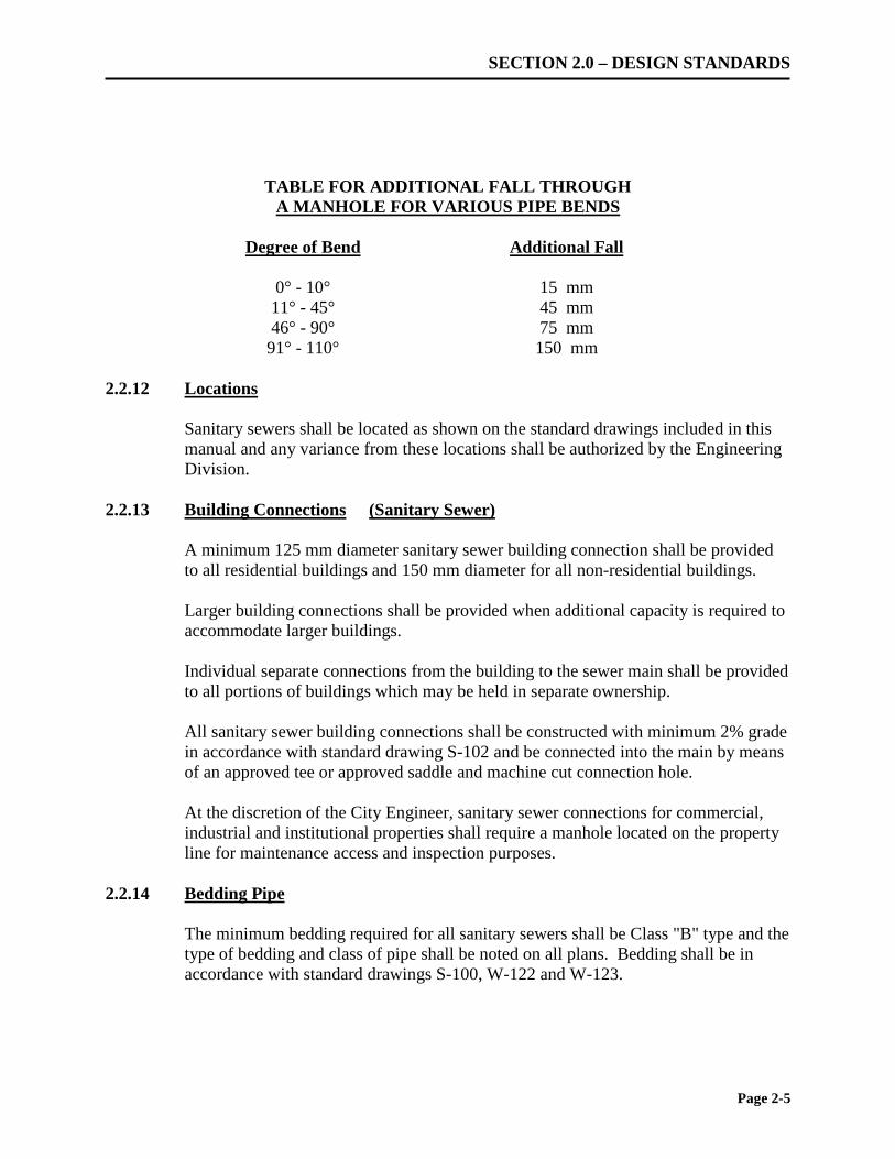
The maximum distance between manholes is to be 110 m with the desired maximum being 100 m. Manholes are required at any change in alignment, grade, size, type and class of pipe. Manholes shall be constructed as shown on the standard drawings included in this manual. If a drop in a manhole is 1 m or greater, a drop connection and manhole shall be constructed. A detail of such shall be included on the construction drawings and be acceptable to the Engineering Division. All manholes exceeding 5.0 m in depth must have a safety platform as per OPSD 404.020 and OPSD 404.021. Where future connections are likely to be made to a manhole, a 1.25 m length of pipe of proper size shall be installed in the manhole and sealed with a standard plug. The obverts of all pipes into manholes shall never be below the obvert of the pipe taking the flow out of the manhole. The extra fall through manholes over the slope of the sewer shall be in accordance with the following table:
Page 2-4
SECTION 2.0 – DESIGN STANDARDS
TABLE FOR ADDITIONAL FALL THROUGH A MANHOLE FOR VARIOUS PIPE BENDS
Degree of Bend Additional Fall
0° - 10° 15 mm 11° - 45° 45 mm 46° - 90° 75 mm 91° - 110° 150 mm
2.2.12 Locations
Sanitary sewers shall be located as shown on the standard drawings included in this manual and any variance from these locations shall be authorized by the Engineering Division.
2.2.13 Building Connections (Sanitary Sewer)
A minimum 125 mm diameter sanitary sewer building connection shall be provided to all residential buildings and 150 mm diameter for all non-residential buildings. Larger building connections shall be provided when additional capacity is required to accommodate larger buildings. Individual separate connections from the building to the sewer main shall be provided to all portions of buildings which may be held in separate ownership. All sanitary sewer building connections shall be constructed with minimum 2% grade in accordance with standard drawing S-102 and be connected into the main by means of an approved tee or approved saddle and machine cut connection hole. At the discretion of the City Engineer, sanitary sewer connections for commercial, industrial and institutional properties shall require a manhole located on the property line for maintenance access and inspection purposes.
2.2.14 Bedding Pipe
The minimum bedding required for all sanitary sewers shall be Class "B" type and the type of bedding and class of pipe shall be noted on all plans. Bedding shall be in accordance with standard drawings S-100, W-122 and W-123.
Page 2-5
SECTION 2.0 – DESIGN STANDARDS
2.2.15 Construction
The construction of sanitary sewers and appurtenances shall be carried out in conformance with the City of Thunder Bay Construction Standards for installation of sanitary sewers. All manholes constructed shall be set to the temporary road grades and then raised when final roadway construction is carried out.
2.2.16 Television Inspection
Prior to acceptance, all sewers shall be inspected using pan and tilt closed circuit television sewer inspection camera. A hard copy report outlining the condition of the sewer shall be submitted for the review of the Engineering Division. The hard copy report shall be accompanied by a colour video of the sewer inspection and a computer disk coded using WRc Defect Coding Standards. The format and media of the video and computer disk shall be approved by the Engineering Division.
2.2.17 Storm Sewers Outfall into Lake Superior and the Neebing McIntrye Floodway
Storm sewers and outfall structures discharging into Lake Superior or the Neebing McIntyre Floodway system shall be designed in consultation with the Lakehead Region Conservation Authority. The storm sewers shall be designed to accommodate backwater effects from normal seasonal/annual fluctuations in water levels of Lake Superior and the Floodway as well as fluctuations resulting from of storm events. The design shall be based on water level fluctuation criteria contained in Lakehead Region Conservation Authority Neebing McIntyre Integrity Evaluation Study.
2.3 STORM WATER MANAGEMENT 2.3.1 Objectives
The City of Thunder Bay follows the recommendations of the Province regarding the implementation of watershed management planning and the promotion of a comprehensive ecosystem approach. All new developments will have storm water management infrastructure that is appropriate for the reduction of the environmental impact of storm water discharge on receiving waters. A Storm Water Management (SWM) plan will be required for all new developments.
Page 2-6
SECTION 2.0 – DESIGN STANDARDS
The SWM plan shall incorporate a combination, where appropriate, of Best Management Practices (BMP), Low Impact Development (LID), and SWM ponds. The guidelines as outlined in the Stormwater Management Practices Planning and Design Manual (Ontario Ministry of Environment et al. 2003) or the latest revision thereof shall be used in the design of storm water facilities and shall comply with the policies of the M.N.R. and Lakehead Region Conservation Authority to the satisfaction of the Engineering Division. The goals of Storm Water Management are: a) to preserve groundwater and baseflow characteristics; b) to protect water quality; c) to protect downstream watercourses from undesirable geomorphic change; d) to minimize the risk of injury and property damage resulting from floods
exceeding the capacity of the piped (minor) storm sewer system and the capacity of the overland (major) storm flow routes;
2.3.1.1 Storm Water Quantity Control Storm water quantity control is required where increased storm runoff, due to development, will cause detrimental impacts via flooding and erosion. A site-specific storm water management assessment will identify the detailed SWM methods required to comply with the City’s policies. Site-specific controls are required where peak runoff exceeds the receiving storm sewer and/or watercourse capacity, or existing flooding or erosion problems have been identified. The minimum control required is to maintain post-development peak runoff at pre-development levels for all events up to the 100 year storm event, matching existing peak flows for all storm events. Typical site storage methods include SWM ponds, rooftop storage, bio-swales, parking lot storage where permitted, and oversizing of pipes. 2.3.1.2 Storm Water Quality Control Water quality controls are to be implemented on all developments in accordance with the MOE’s enhanced level of protection (level 1). Enhanced protection requires the long-term average removal of 80% of suspended solids. At source controls are encouraged where soil conditions allow for infiltration and biological treatment. Subdivision level development will generally incorporate a centralized SWM pond which will provide quality and quantity control functions in combination with lot
Page 2-7

SECTION 2.0 – DESIGN STANDARDS
level and conveyance controls. These ponds will be incorporated adjacent to existing natural features and park facilities. The City will determine safety, aesthetic and maintenance criteria based on each specific development. Separate SWM pond planting plans are required for all new facilities and are to be approved by the City’s Parks Division. Developers are required to maintain and monitor the operation of detention ponds and all SWM facilities to ensure the facility meets the current MOE criteria prior to the City assuming the facility. The developer is responsible to provide an Operation and Maintenance Manual, including a record of all inspection and maintenance works completed while under the developer’s ownership, to the City prior to the City assuming the facility. Small sites such as general commercial and industrial development shall generally include quality controls such as oil/grit separators, however, at the discretion of the City Engineer, alternative methods of stormwater quality control, including the use of Best Management Practices, may be used in place of oil/grit separators and bio-swales. Suppliers shall provide certification of the performance of these devices. The private site owner shall be responsible for the long term operation and maintenance of this type of device. Operation and Maintenance Manuals, including inspection schedules and procedures are to be included with the SWM report and will be added to Site Plan Control and Development Agreements. Oil/grit separators may generally be used for catchment areas of ≤ 2ha where alternative quality control facilities are not feasible. When completing sizing calculations for oil/grit separators, the following requirements shall apply: a) TSS removal efficiency to the Enhanced level of treatment is required, based on
treating 90% of the annual runoff volume, as per the MOE Guidelines. b) The following particle size distribution should be used:
Particle Size Distribution Particle Size Fraction Percent by Mass
[µm] [%] ≤ 20 µm 20
20 µm ≤ x ≤ 40 µm 10 40 µm ≤ x ≤ 60 µm 10 60 µm ≤ x ≤ 130 µm 20 130 µm ≤ x ≤ 400 µm 20 400 µm ≤ x ≤ 4000 µm 20
*Adapted from the MOE SWM Planning & Design Manual (1994) Alternative particle size distributions may only be used if approved by the City Engineer.
Page 2-8

SECTION 2.0 – DESIGN STANDARDS
c) The owner is responsible for inspecting, maintaining, and repair oil/grit separators
located on private property. Operation and Maintenance requirements for oil/grit separators are to be identified in the SWM Brief for the property and shall be implemented by the owner to ensure the continued performance of the unit as designed. Maintenance records are to be provided to the City upon request.
The quality of discharged storm water shall also comply with the City’s Sewer Use By-law (By-law 373-1992).
2.3.2 Minor/Major Systems
The Minor System is the underground piped sewer system designed to carry away storm water from the area in accordance with the City Storm Sewer Design Criteria. The Major System is the overland flow route which will be followed by the storm sewer water when the capacity of the Minor System is exceeded. The route for the major storm flow shall be over publicly owned rights-of-way and open space areas and not through private property. In the event an overland flow route entirely on publicly owned lands cannot be achieved by reasonable regrading of the lands the design engineer may make application to the Engineering Division for approval to drain over privately owned lands. Any approval to allow the major storm route to cross privately owned lands will require the developer to provide specialized drainage plans for the approved locations, wider than normal drainage easements and specialized drainage facilities as may be deemed appropriate by the Engineering Division.
2.3.3 Requirements
All developments shall be designed to minimize the possibility of backup of the minor storm system into any foundation drain system and to provide for the safe overland flow for all storm water in excess of the capacity of the piped storm drainage system.
All roof water shall be discharged onto splash pads on the ground and directed to the street. All lots shall be contoured so that the rear yards will drain to the street. The only exception to this will be situations where existing contours and reasonable regrading by the addition of fill material will not allow front street drainage of the rear yard.
Page 2-9

SECTION 2.0 – DESIGN STANDARDS
Alternate methods of draining rear yards such as swales, catchbasins or through lot drainage will only be considered on a site specific basis and will require a pre-design consultation with the Engineering Division. All paved parking areas larger than 250 m² in area shall be drained by means of catch basins piped to the storm collection system in the area. Catch basins in these areas shall be installed with a Stormceptor oil/grit separator or approved equivalent. At the discretion of the City Engineer, alternative methods of stormwater quality control, including the use of Best Management Practices, may be used in place of oil/grit separators. In instances where the local storm system can accommodate the flows parking lot drainage systems shall be designed to a five year return storm, otherwise the two year return storm shall be used.
2.3.4 Design Brief
The following information is to be contained in a Storm Water Management Design Brief which shall be submitted to the Engineering Division at the time the construction drawings are submitted for review.
a) Criteria for the design of the major/minor storm water systems including runoff
coefficients, storm return period, initial inlet time, pipe friction factors, etc. b) Calculations showing the volume of storm water to be handled by the
major/minor storm water systems from within the development, for tributary areas outside the development and for backwater effects during the major storm event.
The design engineer shall also provide calculations to verify that surface drainage under major storm conditions will not result in significant erosion.
c) A plan of the development showing the major/minor storm systems including all water courses, contributing areas, manholes, catch basins, pipes, outfalls, as well as the major storm route, all drainage easements/rights of way and showing the extent of the flooded area expected during the major storm event.
d) A statement of adequacy stamped by the design engineer certifying the design of
the storm management system(s) is in accordance with good engineering practice, in accordance with M.O.E. Guidelines and that the storm management system(s) will adequately handle a storm which is equivalent to the design storm intensity.
Page 2-10

SECTION 2.0 – DESIGN STANDARDS
The following Table of Contents is a general outline of the contents to be typically included in a Stormwater Management Design Brief: Table of Contents a) Overview b) Existing Conditions & External Drainage Areas c) Proposed Conditions d) Runoff Calculations e) Stormwater Quantity Control f) Stormwater Quality Control g) Operation and Maintenance Plan h) Recommendations and Conclusion e) List of Appendices • Existing and Proposed Runoff Calculations • Storage Calculations and Stage-Storage Discharge • Storm Sewer Design Sheet • Stormwater Management Facility Operation and Maintenance Manual • Existing and Proposed Storm Catchment Drawings
2.3.5 Lot Grading Plan
In order to complement the storm water management design brief and to obtain the necessary approvals to construct the storm water management systems a complete set of grading plans for each lot and the development as a whole shall be submitted.
The grading plan shall show details of the grading of the property and shall include:
a) Existing one metre contours and all existing natural drainage courses on the land
to be developed. b) Existing elevations at each lot corner and at the centre of each lot at a point 10 m
back from the front lot line. c) A review of existing drainage from surrounding properties. The proposed grading
works are to have no negative impact on surrounding properties and must respect and accommodate existing drainage from surrounding properties.
d) Proposed elevations as follows:
- finished road elevations and grades;
- finished grade elevations at all lot corners at each proposed building and at appropriate locations around large or multi-level buildings;
Page 2-11
SECTION 2.0 – DESIGN STANDARDS
- finished grade spot elevations along all swales, ditches, at each catch basin and at appropriate intervals on large sites such as parking lots and open space areas.
e) Details to show how rear lot drainage will be directed to the street. f) Details for all drainage facilities which will be constructed, the size and location
of all proposed drainage easements and the limits of any flooding anticipated as a result of a major storm event.
g) For properties which will not be serviced by sanitary sewers, the location of the
proposed septic field and alternate septic field location shall be shown along with the proposed design finished grade elevation of the septic fields.
h) Where rear drainage is approved by the Engineering Division additional catch
basins will be required as follows:
- at intervals not exceeding 150 m along any drainage swale.
- at any location where drainage from more than 6 urban residential lots or 500 m², whichever is less, is discharged to a roadway.
- at low points and bends in any drainage swale where in the opinion of the
Engineering Division ponding may occur.
i) The location of the Geodetic Datum used as a reference point for elevations on the lot grading plan shall be shown on the lot grading plan.
j) The average slope of residential rear yard surfaces shall not exceed 10% and shall
be measured by dividing the elevation difference by the distance using the following three measurements:
- between the rear of the building and the rear lot line. - between the rear of the building and the centre line of the rear swale. - from side lot line to side lot line over the full width of the lot. - the measurement giving the steepest grade shall govern.
k) The grade difference in the rear yard shall be taken up by the use of grading as
follows:
Page 2-12

SECTION 2.0 – DESIGN STANDARDS
- generally the slope of the rear yard shall be between 1 1/2 % and 5% to maximize the useable area of the rear yard.
- Slopes shall be 1:2 maximum at the extremities of the property when matching surrounding lands.
- retaining walls shall be used to reduce the grade differentials to an acceptable amount wherever the finished grade between two adjacent properties exceeds 400 mm within 1.2m of the interior side lot line unless approved by the Engineering Division or where erosion of soil may occur.
- where retaining walls are proposed they shall be contained on the higher
property.
l) The desirable depth of a drainage swale is 200 mm - 250 mm. Minimum depth shall be 150 mm and the maximum depth shall be 300 mm
m) Drainage flows which are carried around buildings shall be contained in defined
swales located as far from the building as practical.
n) The type of building to be placed on the property shall be determined by the type
of grading which is allowed by the topography of the land. o) Where rear drainage of the lot is approved by the Engineering Division all rain
water downspouts shall be directed to the front of the lot and not directly into any drainage swale.
p) At the Building Permit Stage for lots developed under a Plan of Subdivision or
Consent to Sever through the Committee of Adjustment, and for all developments subject to a Planning Division Agreement, a lot specific grading plan must also be submitted and shall include:
- The proposed outline of the building(s), garage(s), driveway(s), parking lot,
and the property boundary. - Proposed elevations along the perimeter and throughout the site, at each
building corner, along the driveway(s), throughout the parking lot , and along any required swales or drainage features.
- Proposed surface drainage arrows and surface slopes. - The underside of footing elevation(s) and finished floor elevation(s) for the
building(s). - Roof drain outlet locations. - The lot number and municipal address.
Page 2-13

SECTION 2.0 – DESIGN STANDARDS
q) In areas where in the opinion of the Engineering Division existing or future ground water levels may compromise basement construction the following shall be shown on the Grading Plan:
i) Elevation of existing ground water table elevation.
ii) Estimate of future ground water table elevation.
iii) Minimum foundation footing elevation.
r) In areas of development adjacent to water courses the Engineer in consultation
with the Lakehead Region Conservation Authority shall determine the possible effects of hydrostatic ground water fluctuations during storm events on the building foundation and provide minimum footing elevations or other measures to mitigate such effects.
s) Parking lots shall be contoured to pond water to a maximum depth of 300 mm at
each catch basin during the 100-year storm event. Where parking lot storage is used as a form of stormwater quantity control, the 2-year storm event shall generally be stored underground.
2.3.6 Lot Grading
The grading of the lands shall be carried out in accordance with the lot grading plans. Prior to the granting of initial acceptance for the surface work portion of the development, the Developer shall supply the Engineering Division with a certificate signed by his consulting engineer indicating that the property as a whole has been graded in conformity with the lot grading plan.
2.3.7 Storm Sewer Location
The storm sewer shall be located on the road allowance as shown on the standard drawings included in this manual or as otherwise authorized by the Engineering Division. The minimum depth of cover on the storm sewer shall be 1.5 m below the road surface measured to the top of the pipe.
2.3.8 Pipe Sizes and Strength
The minimum size of all storm sewer pipe shall be 300 mm diameter. Pipe sizes up to and including 375 mm diameter shall be P.V.C. sewer pipe having a minimum S.D.R. of 35 conforming to O.P.S.S. 1841.
Page 2-14

SECTION 2.0 – DESIGN STANDARDS
Pipe sizes larger than 375 mm diameter shall be reinforced concrete pipe conforming to CSA A257.2-M1982 strength classification 100-D. (formerly Class IV). At the discretion of the City Engineer, HDPE pipe meeting the criteria outlined in Section 2.3.17 may be used for pipe sizes up to and including 900mm diameter. Additional testing and inspection may be required where HDPE is approved for use, including deflection testing in accordance with OPSS 410.
2.3.9 Manholes
Manholes shall be located not more than 110 m apart and the same requirements as for sanitary sewer manholes are to be met. Drop manholes are not required for storm sewers of 450 mm diameter and larger. All manholes exceeding 5.0 m in depth must have a safety platform as per OPSD 404.020. The fall through manholes over the slope of the sewer shall be in accordance with the table provided in Section 2.2.11. Where catch basin manholes are approved for use, a minimum sump depth of 300mm is required.
2.3.10 Building Connections (Storm Sewer)
Storm sewer connections to single family residential buildings when provided shall be minimum 100 mm diameter and be constructed in accordance with standard drawing S-103. The minimum grade for all residential storm sewer building connections shall be 2%. All storm sewer building connections into storm sewers shall be made using an approved tee or approved saddle and machine cut connection hole. Any roof drainage shall be directed to the surface and shall not be directly connected to the storm sewer unless permission has been received from the Engineering Division. Individual separate connections from the building to the sewer main shall be provided to all portions of buildings which may be held in separate ownership. At the discretion of the City Engineer, storm sewer connections for commercial, industrial and institutional properties shall require a manhole located on the property line for maintenance access and inspection purposes.
Page 2-15

SECTION 2.0 – DESIGN STANDARDS
2.3.11 Rainfall Intensity
The rainfall intensity shall be determined from the curves listed in the standard drawings included in this manual.
Assuming a major system can be adequately provided and foundation drains are not connected by gravity to the storm sewers, the criteria for the design of the minor system would be a 2-year return storm. The combination of the minor and major system should be checked for a total capacity to accommodate either the regional storm or the 100 year storm event whichever results in the greater rainfall. Where overland flows can cause unacceptable flooding on roadways or on private property, the minor system shall be enlarged to reduce the flooding to acceptable levels. Storm sewers on arterial roads and trunk storm sewers shall be designed for a 10-year return period. Storm sewers, in areas where flooding will cause an unacceptable barrier to access or in low lying areas susceptible to flooding, shall be designed for a higher return period at the discretion of the Engineering Division. The initial inlet time for runoff entering the storm system shall be ten minutes including overland flow time unless otherwise authorized by the Engineering Division.
2.3.12 Calculating Runoff Flows
For areas of five hectares and larger, a UNIT HYDROGRAPH program such as PCSWMM or Visual OTTHYMO or other suitable technique shall be used to calculate the flows. For areas less than five hectares the RATIONAL METHOD for calculating flows may be used. When using the "Rational Method" of calculating flows the following design criteria shall be used.
Q = 2.78 A.I.R.
Where Q= Peak Flow in litres/second (L/s) A= Area in hectares (ha) I = Rainfall intensity in millimeters/hour (mm/hr) R= Runoff co-efficient
Page 2-16

SECTION 2.0 – DESIGN STANDARDS
2.3.13 Runoff Co-efficients
a) Residential
1. With rear lot drainage not flowing directly onto the R = 0.40 street, area including road allowance plus 15 m from the street line on both sides Remainder of Lot area R = 0.20
2. When all of the lot slopes toward the street, total R = 0.30 area plus the road allowance
3. Row Housing R = 0.60
b) Park Land R = 0.20
c) Playgrounds R = 0.25
d) Commercial and Industrial
e) Asphalt, Concrete, & Roof Areas
R = 0.60 to 0.75 R = 0.90
For new developments, the runoff co-efficient shall be calculated based on the breakdown of pervious and impervious areas using the values provided above and the Ministry of Transportation Drainage Management Manual Design Chart 1.07 (latest edition).
ALLOWABLE INFILTRATION/EXFILTRATION
The allowable infiltration/exfiltration for sewer pipe shall not exceed 0.075 litres per millimeter of pipe diameter per 100 metres of sewer pipe. Infiltration/exfiltration shall be measured in accordance with O.P.S.S. 410.
2.3.14 Roughness Co-efficient
When capacities of pipe are calculated using the Manning Formula the roughness co-efficient "n" shall not be less than 0.013 for all smooth walled pipe and 0.025 for corrugated metal pipe.
2.3.15 Velocity
All sewers shall be designed and constructed to give when flowing full a minimum velocity of 0.80 m/s and a maximum velocity of 6.0 m/s unless otherwise authorized by the Engineering Division.
Page 2-17
SECTION 2.0 – DESIGN STANDARDS
All sewers with slopes such that flow velocities will approach “critical velocity” shall be designed so as to reduce turbulence. All sewers shall be designed and constructed so that surcharging above the pipe obvert from backwater condition does not occur. In the event the surcharging under backwater conditions is deemed minor in the opinion of the Engineering Division and mitigating measures are not required to eliminate such surcharging the following conditions shall be complied with:
a) The level of surcharging in the sewer shall be plotted on the profile view of the
sewer. b) The surcharging shall not extend into any lateral connection past the property line
of any land served by the sewer. 2.3.16 Catch Basins
Catch basins shall be not more than 100 m apart with each side of the road being considered separately. Catch basins shall be constructed at the low points in the road grade and at the beginning of corner curves at intersections to catch the water before it flows around the corner. The following spacing for catch basins are recommended: - 100 m apart with road grades up to 3% - 90 m apart with road grades from 3.1 % - 4.5%
- 75 m apart with road grades over 4.5%
- in instances where the Engineering Division approves the construction of a road
with a grade in excess of 6% double catch basins shall be used. Catch basins shall be installed at mid-lot locations to avoid conflict with driveway entrances and shall not be installed at locations which coincide with fire hydrant locations. Catch basins shall be connected into the storm sewer at manholes using Polyvinyl Chloride (PVC) SDR 35 pipe. The connection into each manhole shall be made so that the flow from the catch basin does not oppose the flow in the sewer.
Page 2-18

SECTION 2.0 – DESIGN STANDARDS
Catch basins which do not have a sump shall not be connected directly into the storm sewer system.
2.3.17 Culverts
Roadway cross culverts under arterial roads shall be designed to accommodate a storm with a twenty-five year return period. All other roadway cross culverts shall be designed to accommodate a ten year return storm. Driveway culverts on arterial roads and in other locations where flooding will result in unacceptable damage or barrier to access shall be designed to accommodate a ten year return storm unless otherwise authorized by the Engineering Division. Driveways in these locations shall require edge of driveway surface protection (concrete headwalls, rip rap, asphalt). The method of edge protection applied shall be reviewed and approved by the Engineering Division prior to construction. Construction methods for pipe culvert installations shall be in accordance to OPSS 421 as they apply to the specifications listed below. Driveway and roadway culverts shall be either aluminized type 2 corrugated steel pipe or high-density polyethylene (HDPE) pipe and shall meet the following specifications: Aluminized Shall have a minimum wall thickness of 2.0 mm, subject to the following exceptions: a) Driveway culverts 300 mm in diameter or smaller with 300 mm or more of earth
cover may be 1.6 mm wall thickness. b) The wall thickness of driveway and roadway culverts of sizes larger than 900 mm
shall be determined by the Engineering Division on a site specific basis.
HDPE
Shall be an open profile HDPE pipe (corrugated exterior with a smooth interior wall) manufactured according to CSA B182.8 and certified by an independent 3rd party agency as per OPSS 1840. The minimum pipe stiffness shall be 320 kPa and the maximum diameter shall be 900mm.
Page 2-19

SECTION 2.0 – DESIGN STANDARDS
Pipe joints shall typically be type 3 (external split coupler) with the exception where water tight gaskets are specified for certain applications. Install metal locate piece (U bolt) at ends of HDPE culverts.
2.3.18 Television Inspection
Prior to acceptance, all sewers shall be inspected using pan and tilt closed circuit television sewer inspection camera. A hard copy report outlining the condition of the sewer shall be submitted for the review of the Engineering Division.
The hard copy report shall be accompanied by a colour DVD of the sewer inspection and a computer disk coded using WRC Defect Coding Standards. The format and media of the DVD and computer disk shall be approved by the Engineering Division.
2.3.19 Erosion Protection and Sediment Control
During the course of construction temporary erosion protection and sediment control measures shall be provided and maintained to the satisfaction of the Engineering Division.
2.3.20 Catch Basin Retrofit - Policy
In order to address drainage concerns of privately owned occupied lands which are not subject to a current land development proposal the following criteria shall be used to determine the need for installation of a publicly funded and maintained catch basin: 1) Areas involving more than one lot which have historically been subject to
repeated flooding which for topographical reasons cannot be resolved by filling or regrading.
2) Areas involving public lands including open space, lanes, road allowances which
for topographical reasons cannot be drained on surface and are impacting surrounding private lands to the extent that the City will incur liability.
Catch basins will not be installed by the City to correct flooding involving only a single lot. Such situations will require the lot owner to privately install and maintain the necessary catch basin and associated piping.
Page 2-20
SECTION 2.0 – DESIGN STANDARDS
Prior to the installation of any catch basin and piping the land owner shall obtain all necessary approvals for the design and construction of the works from the Engineering Division. All catch basins and associated piping constructed on privately owned lands shall be placed on an easement. The width of any easement shall be determined in accordance with Section 2.4.12.
Due to limitations on depth of bury of catch basin piping and accessibility limitations of catch basins, such facilities are subject to periods of time when they are inoperative resulting in temporary flooding.
The City will not accept liability for the consequences of such flooding.
The decision to install any publicly funded and maintained catch basin and associated piping shall be subject to available funding and shall be priority at the discretion of the Engineering Division.
2.4 ROADWAYS, CURBS, GUTTERS, SIDEWALKS, AND PARKING LOTS 2.4.1 General Construction
All roads, curbs, gutters and sidewalks shall be constructed in accordance with the City of Thunder Bay Engineering Standards. All geometric design shall conform to the Transportation Association of Canada Geometric Design Guide for Canadian Roads (TAC). As part of land development projects the proponent shall prepare a transportation analysis showing street classifications within the development and the effects of traffic from the development on streets that abut or may be affected by the development for the approval of the Engineering Division. The width and cross section of the roads being constructed shall be as indicated on the applicable standard drawing for the classification of roads called for in the transportation study. At the discretion of the City Engineer, two points of access / egress will be required for all residential developments greater than 25 lots or 25 units.
Page 2-21

SECTION 2.0 – DESIGN STANDARDS
2.4.2 Radii
The minimum curb radius for the intersection of local streets shall be 8.0 m. This minimum radius shall be increased as required when local streets intersect at angles other that 90° and when the intersection involves collector or arterial streets. When intersections involve collector or arterial streets the intersection radii shall be determined by using the appropriate turning movement design templates for the type of vehicular traffic which could be reasonably expected to use the intersection. The minimum curb radius for intersections involving arterial roads shall be 12.0 m.
2.4.3 Road Grades
The minimum road grades on all streets shall be 0.30% with preferable being 0.50%. The maximum grade shall be 6% on all streets unless otherwise approved by the Engineering Division. To maintain a route for the major storm drainage system, sags in roadways between intersections are not acceptable, unless a suitable overland outlet is provided.
2.4.4 Concrete
Concrete curb and gutters as required shall be built as indicated on the standard drawings included in this manual. Allowable amounts of air shall be 7% air entrainment + or – 1.5% unless otherwise specified.
2.4.5 Sidewalks
Sidewalks in residential developments shall be 1.5 m wide. The running slope of sidewalks should not exceed 1:20 (5%) unless unpractical due to the physical terrain. Sidewalks as shown on the standard drawings included in this manual shall be constructed on all streets in accordance with the current revision of Corporate Policy Number 11-03-07, (Sidewalk Construction in New Development Areas). At the discretion of the City Engineer, new developments subject to Planning Division Agreements will be required to either construct new sidewalks along their property limits in accordance with this Policy, or to provide deferred service payments for the future installation of sidewalks by the City.
Page 2-22

SECTION 2.0 – DESIGN STANDARDS
2.4.6 Pavement Construction
a) All roadways shall be designed to satisfy the following minimum performance standards:
1. Pavement, curbs, sewer manholes, catch basins shall not be subject to
cumulative damage from movement due to frost action.
2. During the first two years of service after the placement of top lift, any cracking of the pavement shall be minimal and shall be repaired by the developer in accordance with the City’s Pavement Management System Guidelines.
3. The pavement shall not require resurfacing for at least 15 years. 4. All pavement shall be warranted by the developer for a minimum period of
two years from the date of installation of the second lift. (This requirement is subject to the acceptance provisions for surface works contained in this manual)
b) Prior to the City granting approval for the construction of roadways, the developer
shall submit, for approval of the Engineering Division, a complete set of construction drawings prepared by a Professional Engineer for the roadways showing details of the proposed construction. The construction drawings shall be supplemented by a design brief prepared by a Professional Engineer specializing in Soils Engineering which include a review of the following:
1. Log of bore holes showing soil types and their depths. 2. Geodetic elevation of the water table including estimates of potential
variations. 3. Volume of traffic and loads to be expected. 4. Make reference to the design criteria outlined in Section 2.4.6 (a) 5. Review ground water conditions and potential variations to determine the
need for subsurface drainage facilities. 6. Identify the proposed use of the land served by the road as well as traffic
volumes and loads to be expected.
Page 2-23

SECTION 2.0 – DESIGN STANDARDS
7. Determine additional road base requirements (if any) required to accommodate construction traffic on partially completed roadways.
8. Determine proposed design for pavement structure, road base, subbase and
any subsurface drainage and specify the thickness of the asphalt and granular layers.
c) The minimum road base design shall consist of two (2) - 40 mm layers HL4
asphalt, 150 mm Granular “A”, 500 mm Granular “B” all atop a road sub-base free from organic or frost susceptible material.
d) The mix design for all asphalt pavement shall be approved by the Engineering
Division prior to placing.
e) Paved roadways with curb and gutter shall not be left indefinitely with only one layer of asphalt without suitable arrangements made to eliminate standing water on the pavement. Any such arrangements to disperse the standing water shall be proposed to the Engineering Division for approval prior to any pavement being laid. In the event that suitable arrangements to disperse the standing water are not approved then the second layer of asphalt paving must be placed immediately. The responsibility for the repair of any damage to the finished roadway shall remain with the developer until final acceptance has been granted.
2.4.7 Boulevards
The boulevard shall be that area lying between the shoulder of the road or the concrete curb and the property limits of the adjacent private property not occupied by a sidewalk. The boulevards shall have a uniform rising grade from the finished roadway to the property limits of minimum 2% where feasible. Deviation from this will be permitted depending on the existing contours in the area. The boulevards shall be sodded as outlined in Section 2.4.9.
Exceptions
Where the distance between the edges of the sidewalk and the curbing is less than one (1) metre, the area may receive an asphalt surface, subject to the approval of the Engineering Division.
Page 2-24

SECTION 2.0 – DESIGN STANDARDS
2.4.8 Walkways, Ramps and Stairs
Walkways shall be that area lying between the limits of adjacent private properties designated for pedestrian access between streets to parkland, commercial or institutional sites. All walkways shall have a 1.50 metre concrete sidewalk constructed on them for pedestrian travelers, and the walkway shall be fenced on both sides with a 1.829 m high chain link fence along the length of the walkway, with the exception of the portion of the fence that is located within the front yard set-back, which shall be 1.219m in height. Walkways shall be sodded as outlined in Section 2.4.9, between the sidewalk and the fence. The running slope of walkways should not exceed 1:20 (5%) unless unpractical due to the physical terrain. Walkways that have a running slope greater than 1:20 (5%) and elevate the person above the surrounding terrain shall be considered a ramp. The maximum allowable running slope for a ramp shall be 1:12 (8.3%). The maximum cross slope of a ramp surface shall be 1:50 (2%). Ramp designs shall include all required landings, handrails, and edge protection as defined by the applicable design code. Stairs shall have uniform riser heights (rise) and uniform tread depths (run). The stair riser height shall not be more than 175mm and not less than 125mm. The stair run depth shall not be more than 355mm and not less than 280mm. Handrails shall be installed on both sides of all stairs at a uniform height ranging between 865mm and 965mm above the stair nosing.
2.4.9 Sodding and Seeding
The owner shall furnish all top soil, labour, material and equipment as required to complete the work as described. Within the Street Right of Way, Walkway Blocks, or City Easement Prior to the placing of top soil and sod the total area shall be fine graded to a uniform surface 100 mm minimum grade below controlling grade factors such as curbs, road shoulders, manholes, etc., to allow for the placing of a minimum of 75 mm of top soil and 25 mm of sod. All sub-grades shall be loosened to a depth of 150mm prior to leveling (especially where heavy equipment has been in operation) allowing a bonding of top and sub-soil, for adequate root expansion.
Page 2-25

SECTION 2.0 – DESIGN STANDARDS
Top soil shall be as per master project specification Section 02530 Landscaping and be free of roots, stones or other foreign debris. Soils infested with seeds or roots of noxious weeds will not be acceptable. . Sod shall not be less than 300 mm in width nor wider than 500 mm. Sod of the 25 mm soil thickness will be the minimum acceptable. All sod shall be taken from loamy soil, free from weeds, in a healthy growing condition without sign of decay and containing sufficient moisture to maintain vitality during transportation and placing.
Sod shall be laid lengthwise across the face of slopes or parallel to curbs with ends close together. Joints in adjacent rows shall be staggered. Joints and broken sod shall be rolled or tamped to a uniform surface. Sod shall be harvested, delivered and installed within a period of thirty-six (36) hours and shall not be laid in a frozen condition nor laid on frozen soil. The entire work shall be done in a thorough manner, achieving upon completion a quality natural turf approximately even with the top of the curb (where applicable). The developer shall be responsible for the care and maintenance of sodded areas for a period of one (1) year from the date of initial acceptance. During this period any defects caused by slope failure, soil compaction or failure of the sod to grow will be repaired, removed and replaced with fresh live sod. Seeding can only be used in the Right of Way when authorized by the Engineering Division. Within Park Lands When installing topsoil and sod or seeding in Park Lands the latest revision of the Parks Division Standards and Specifications shall apply.
2.4.10 Specifications for Drivable Gravel Roads for New Subdivisions
Road(s) in a land development project which is in the construction phase shall be constructed to a "drivable gravel standard" prior to the issuance of building permits for lots in the development. The following conditions shall be met in order to meet the drivable gravel road standard:
a) The design engineer shall certify that the road is capable of carrying the
anticipated loading of construction traffic at this partially completed stage.
Page 2-26

SECTION 2.0 – DESIGN STANDARDS
b) All clearing, brushing and excavation of the road allowance must be complete. c) All granular "B" must be in place up to the designated elevation for "top of
granular "B" as indicated on the construction drawings. d) The granular "B" road base shall be compacted to 90% proctor density and be
graded to have sufficient crown to provide adequate drainage for the roadway surface
e) The road base shall be constructed to full design width of the proposed road and
all dead-end roads shall have a turning basin of adequate size to accommodate emergency vehicles and Roads Division maintenance equipment.
f) All manholes, catch basins, valve boxes and other appurtenances shall be lowered
to be flush with the gravel road surface. Manholes may be temporarily covered with steel plates in lieu of frames and covers if necessary to accommodate this requirement. The steel plates shall have steel legs or lugs attached to prevent being pushed off the manhole structure.
g) The storm water collection system which is proposed for the completed road shall be complete to the extent that it is operational and can provide adequate drainage of the gravel road.
h) The road shall be graded to provide adequate drainage into the storm water
collection system. i) The developer of the land shall maintain the road in a driveable state at all times
and shall take whatever action is necessary to ensure proper drainage of the road.
j) The developer shall ensure that any or all underground utilities are properly covered and that all construction materials and construction debris are removed from the road allowance.
The developer shall carry out the above-noted requirements prior to the Engineering Division notifying the Chief Building Official that "sufficient work has been carried out by the developer so as to warrant this issuance of building permits for the lots in a development". Following the issuance of building permits the Roads Division will snow plough the roads within the development on which building permits have been issued as well as any roads providing access to the said road. All plowing will be on a "non-priority basis".
Page 2-27

SECTION 2.0 – DESIGN STANDARDS
Any additional costs incurred by the Roads Division due to non-compliance with the above-noted requirements will be chargeable to the developer of the land.
2.4.11 Parking Lots
In the instance where the construction of parking lots falls under the jurisdiction of the Engineering Division as is the case in Site Plan Control Agreements, Condominium Agreements and Development Agreements, such parking lots shall be constructed to the following standards: a) See Section 2.3.3 for grading requirements for parking lots. b) All paved parking area and entrances shall have a minimum of 40 mm thick HL4 asphalt paving on 80 mm thick granular "A" base over a suitable granular sub- base.
Entrances and/or parking areas which are subject to heavy loads or high traffic volumes shall be designed and constructed for such traffic. The Engineering Division may require the design of proposed parking areas to be certified by a professional engineer.
c) All entrances and parking areas shall be curbed to prevent vehicular encroachment onto adjacent public sidewalks and boulevards.
d) All parking lot illumination shall meet the minimum requirements of I.E.S.
(Illuminating Engineering Society) guidelines and shall be installed in accordance with Section 6.2.
2.4.12 Easements
In order to accommodate the ongoing maintenance of services which are constructed, easements will be required for those services which are outside of normal service corridors. All easements which are provided to the City of Thunder Bay shall be of sufficient width for excavation of the services in conformity with current Occupational Health and Safety Regulations without the need for excavation aids such as trench boxes or sheet piling. In determining the width of easements required to provide maintenance access to a particular service, the depth of the service and anticipated soil type will be considered. The minimum easement required shall be wide enough to allow and excavation with side slopes of 1:1 or flatter.
Page 2-28
SECTION 2.0 – DESIGN STANDARDS
2.4.13 Trees
All municipal trees must be selected and planted in accordance with the latest edition of the Parks Division “Standards and Specifications”. This document can be downloaded from the City of Thunder Bay web site.
2.4.14 Bike Lanes
Dedicated bike lanes may be required where an existing commuter route exists, or where an extension to the commuter route is being proposed by the Engineering Division. Bike lane widths and configurations shall be designed in accordance with the Transportation Association of Canada “Bikeway Traffic Control Guidelines for Canada”, and shall accommodate all required vehicle lanes and parking along the commuter route. The following lane dimension criteria shall apply: Minimum Bike Lane Width with Parking - 1.5m Minimum Bike Lane Width with no Parking - 1.2m
2.4.15 Signs
All regulatory, warning, guide and information signs shall be in accordance with the Ontario Traffic Manual.
2.4.16 Transit Facilities
All transit facilities shall be constructed in accordance with the Transit Accessibility Design Guidelines for the City of Thunder Bay.
2.4.17 Separation from Municipal Services and Utilities
The following separation distances are provided for general information purposes (all “preferred” separations are to be provided unless otherwise approved by the City Engineer):
a) Storm and sanitary fixtures (catch basins and manholes) from hydro ducts – 1.0m
preferred separation, 0.5m minimum separation.
b) Water fixtures (water valves) from hydro ducts – 2.0m preferred separation, 1.5m minimum separation.
c) When civil service mains (storm, sanitary, and water in the right-of-way) are
running parallel to hydro ducts, 3.0m preferred separation.
Page 2-29

SECTION 2.0 – DESIGN STANDARDS
d) Civil service connections (storm, sanitary, and water into private property) from hydro secondary services, 2.0m preferred separation.
e) All civil services must be located a minimum of 3.0m away from transformer bases,
which is equivalent to a minimum 2.0m away from the grounding grid.
2.5 WATER SYSTEMS 2.5.1 Cathodic Protection
Water systems shall be designed to include cathodic protection as specified under section 8.0.
2.5.2 Water Demand
Water supply systems shall be designed using the City of Thunder Bay Water System Model. The model has been designed to use Epanet computer software to simulate flows for present day and the year 2015. This water system model shall be used to determine system pressures under the following conditions for both present day and the year 2015: a) Minimum daily demand - (reservoirs full). b) Maximum daily demand. c) Maximum daily demand and fire demand. d) Maximum hourly demand. The water system shall be designed to satisfy the greater of these demands. All updates to the City of Thunder Bay Water System Model will be completed by the City of Thunder Bay’s water modeling consultant. All data required for the assessment of new developments and new water supply systems shall be provided to the City by the developer’s consulting engineer. For private developments where the new water supply system will not be transferred to the City, the developer shall reimburse the City for the cost to update the Water System Model.
2.5.3 Peaking Factors
The following peaking factors shall be used in conjunction with an average day per capita consumption of 600 litres for domestic use and 700 litres for a mix of domestic, commercial and industrial usage. Design water demands and associated peaking factors for flows other than residential or domestic flows shall be in accordance with proposed design water demands contained in the M.O. E.E. “Guideline for the Design of Water Distribution System”.
Page 2-30

SECTION 2.0 – DESIGN STANDARDS
Population Minimum Maximum Day Peak Rate Factor
Range Factor Rate Factor Factor (Max.Hr.)
Up to 500 .40 3.00 4.50 500 - 1000 .40 2.75 4.13 1001 - 2000 .45 2.50 3.75 2001 - 3000 .45 2.25 3.38 3001 - 10000 .50 2.00 3.00
When analyzing larger areas appropriate peaking factors shall be used. The water system model contains peaking factors which shall be used for City wide analysis.
2.5.4 Fire Demands
In order to estimate the fire flow demand for water system extensions the designer shall take into consideration all applicable existing and proposed structures on the affected land. Design flows shall be in accordance with Part 3 of the Ontario Building Code and the Ontario Fire Code. The designer is also referred to the Publication “Water Supply for Public Fire Protection - A Guide to Recommended Practice, 1999”, prepared by Fire Underwriters Survey, Insurer’s Advisory Organization. The minimum fire flow for residential land developments with detached dwellings shall not be less than 4550 L/min. Background Fire hydrant flow tests are undertaken to obtain actual flow rates and pressures at certain locations within the water distribution system. The rates of flow, static and residual system pressures as well as system operating parameters (SCADA System Data) all obtained at the time of the flow test are used to calibrate our Water System Model. The calibrated model is used to estimate available flows and pressures under various predetermined operating conditions for the purpose of designing fire suppression systems and planned expansions of the water distribution systems. The Following Information is required at the time of the test: 1. Date and time of test.
Page 2-31

SECTION 2.0 – DESIGN STANDARDS
2. Hydrant ID numbers for Flow and Residual Pressure Hydrants and Street Name from Fire Hydrant Database or Engineering Division mapping.
3. Flow each hydrant(s) using a single nozzle and at least two nozzles to provide
varying rates of flow. Ensure that a different in pressure drop of at least 105 KPa. (15 PSI) is attained in the tow test results.
The range of flows for each test shall be predetermined depending on the purpose of the flow test. Flow tests for the design of Private fire Protection Systems (sprinklers and/or standpipes) the hydrants(s) shall be at a rate equal to the design flow of the sprinkler/standpipe system and a rate equal to the flow required from the fire hydrant(s) serving the site. If the design flow of the sprinkler/standpipe system or the required flow rate for the subject hydrant cannot be attained then the hydrant shall be flowed at its maximum flow using both hose ports simultaneously. The rate of flow required for the sprinkler/standpipe system shall be obtained from the Fire Protection System designer requesting the flow test. The rate of flow required for the fire hydrant serving the site can be obtained from the Engineering Division.
4. Record Pitot Gauge Pressures for each nozzle flowed. Use the Darley Nozzle
Discharge Table to calculate the actual flows.
5. Record System Pressure for zero flow and for each measured flow. System Pressures shall be read at the Residual Pressure Hydrant.
6. Obtain the Geodetic Elevation of the Flow and Residual Pressure Hydrants from
Engineering Division topographical records.
7. Record the following information at the time of the test for the applicable pressure zone from Water Treatment Plant shift operator (683-8141 ext 4).
- Name the Applicable Reservoir - Reservoir level at start and end of flow test - Reservoir inflow and outflow rate - Pump on/off status at Station (s) which would impact the test (i.e. Bare Point
for Zone 1N and Broadway for zone 2S) - Suction and Discharge pressures of pumps - Discharge flow from stations
8. Complete Flow Test Report and forward to the Engineering Division.
Page 2-32
SECTION 2.0 – DESIGN STANDARDS
2.5.5 Private Fire Protection Systems
All private fire protection systems shall be equipped with a backflow prevention device to the satisfaction of the Environment Division. For buildings requiring fire protection, individual connections shall be provided outside the building for fire and domestic services with separate shut off/isolation valves outside the building, and a valve located on City property. All private fire protection systems which will depend on the Municipal Water System shall be designed to provide the required flows at a static supply pressure not greater than the minimum pressure designated in the M.O.E. Guidelines for water distribution systems on the day of maximum system demand (350 KPa - 50 psi).
If it can be shown to the satisfaction of the Engineering Division using flow records and appropriate water system modelling that a higher supply pressure in the water system may be approved as a basis for design purposes. In this case, the Engineering Division may require the system to be designed to enable upgrading in the future to operate under a static pressure of 50 psi with minimal impact on the building: 1. Determine appropriate location for Flow and Residual pressure Hydrants. The
Flow Hydrant should be as close as possible to the subject site. The Residual Pressure Hydrant should be a hydrant that is connected to the main that carries the
2. Largest flow to the site (if identifiable) and be as close as possible to the Flow
Hydrant.
3. Undertake the flow testing of appropriate Fire Hydrants adjacent to the subject property.
4. Obtain all information required by “Information Required for Fire Hydrant Flow
Tests”.
5. Using the obtained information and Approved Software, model the water system for Maximum Day conditions for both Present Day and Year 2015.
6. Private Fire Protection Systems shall be designed to operate on a maximum
available Water System Static Pressure at the service connection of 350 KPa (50 PSI). The system shall be designed to include all necessary equipment with pipes sized to provide the required flows and pressures at the maximum available static pressure of 350 KPa (50 PSI).
Page 2-33
SECTION 2.0 – DESIGN STANDARDS
7. In the event that modeling shows the available static pressure is lower than 350 KPa (50 PSI) then the system shall be designed to operate at the lower pressure.
In the event that modeling shows significantly higher static pressures are available a second design may be undertaken to determine the pipe sizes and equipment necessary for the Private Fire Protection System to operate at the higher pressure. The installation of any of the equipment required to operate at the 350 KPa (50 PSI) pressure can be deferred; so long as provisions are made to allow the installation of the deferred equipment at a later date if necessary, with minimum disruption to the building. Such provisions may consist of but are not limited to the following: a) Dedicated space within the building for future installation of pumps, generators, and addition electrical service capacity; b) Additional piping and fittings blanked off with caps, blind flanges etc. as required to accommodate the simplified installation of the additional equipment at a later date etc.
8. The building owner shall be responsible for all costs for the retrofitting of the
Private Fire Protection System in the event of a change in supply pressure of the water system.
9. All non-metered dedicated fire supply piping shall be equipped with alarmed flow
detection equipment in accordance with Part 3 of The Ontario Building Code and to the satisfaction of the Engineering Division.
Page 2-34
SECTION 2.0 – DESIGN STANDARDS
2.5.6 System Pressures
The water distribution system shall be sized to function within the following parameters: a) Under minimum daily demand conditions with reservoirs at the maximum level
water system pressures shall not exceed 700 KPa. (100 psi)
b) Homes subjected to water pressures exceeding 550 KPa (80 psi) shall be equipped with a pressure regulating device to maintain water pressure in the home at less than 550 KPa.
c) Under maximum daily demand water system pressure shall be not less than 350
KPa. (50 psi) d) Under maximum hourly demand system pressures shall not be less than 275 KPa.
(40 psi) e) Under maximum daily demand plus fire demand system pressures shall not be
less than 140 KPa. (20 psi)
2.5.7 Friction Factors
The following Hazen- Williams "C" values shall be used for all new pipe for the design of distribution systems regardless of material:
Diameter "C" Factor
150 mm 100
200 mm - 300 mm 110 300 mm - 600 mm 120
Existing pipes shall be analysed using “C” valves which are appropriate for the age and condition of the pipe. The estimating of appropriate “C” valves may require the developer to under take field flow testing of the existing watermains.
Page 2-35

SECTION 2.0 – DESIGN STANDARDS
2.5.8 Minimum Size of Watermains
The following shall be used as the standard for minimum size of mains used for hydrant supply: a) Residential Areas - 200 mm diameter main shall be used with the exception that
150 mm diameter main may be used where it completes a good gridiron with intersecting mains located at not more than 180 m intervals.
b) Mercantile and Business Districts - 200 mm diameter main shall be used. c) Dead end watermains not required for hydrant supply shall be sized to prevent
stagnation of the water in the main. 2.5.9 System Layout
a) Dead-End Mains - Where possible, water distribution system layouts shall be designed to eliminate dead-end sections. Where dead-end mains cannot be avoided, there shall be provided a fire hydrant, or other acceptable measure to prevent problems associated with water stagnation. At the discretion of the City Engineer, all significant new developments, including residential developments greater than 25 lots or 25 units, shall require a looped watermain system to be provided.
b) Valves - Gate valves in direct bury valve boxes shall be installed on all water
mains equal to and less than 400 mm in diameter. Butterfly valves in valve chambers shall be installed on all watermains greater than 400 mm in diameter.
Valves in direct bury valve boxes shall be installed in line with the property lines at intersections and at a spacing not to exceed 275 m in continuous watermains. Valves in valve chambers shall be installed at a spacing not to exceed 425 m. In grid patterns, intersecting watermains shall be equipped with a minimum number of shut-off valves as follows:
Page 2-36

SECTION 2.0 – DESIGN STANDARDS
Number of Valves
"T" Intersection at least 2 valves
Cross Intersection at least 3 valves
All valves at intersections are to be installed in line with the property line of the intersecting street. The maximum spacing between valves shall not exceed 275 m in any continuous watermain. The maximum spacing of valve chambers shall not exceed 425 m.
c) Hydrants - All hydrants shall be installed 3.75 m back from the corner, formed by intersecting street lines and 2.75 m out from the street line except where the Engineer directs otherwise. Hydrants located in mid-block areas shall be located near the centre of a lot to avoid interference with driveways. Hydrants shall be spaced so that the average area of coverage shall not exceed 10,000 square metres per hydrant in principal mercantile areas or 15,000 square metres per hydrant in built-up residential areas. The spacing of hydrants shall not exceed 90 m in business districts or 150 m in residential areas.
d) Depth of Watermains - At least 2.15 m of cover shall be provided for all
watermains and house services. In no case shall a watermain be laid with over 2.75 m of cover or a building service at a depth of cover over 2.5 m.
In areas of rock where the developer has obtained approval from the Engineering Division to install building service pipes at less than 2.15 m of earth cover the minimum earth cover shall be 1.5 m. The water service pipe shall be insulated with “Ducted Tube” insulation and heat traced. The insulation and heat tracing of the water service pipe shall be an “Engineered Design” and shall be custom designed for each specific application.
e) Separation from Sewers - Except in areas of rock, all sewer and watermains shall be laid with a minimum horizontal separation of 2.50 m. Where sewer and watermains in areas of rock are laid in the same trench, the horizontal clear distance between sewer and watermains shall not be less than 600 mm horizontal with a vertical distance between the bottom of the watermain and the top of the sewer of not less than 500 mm.
Page 2-37

SECTION 2.0 – DESIGN STANDARDS
f) Building Service Connections - The minimum size of house water service
connections shall be 20 mm with larger sizes being used where required by water demand, lengths of service connections or area water pressure. Services shall be designed to maintain a minimum 240 KPa water pressure at the house water meter under maximum building water demand. Streets with curb and gutter shall have the service curb stop located 2.4 m out from the property line. On streets with ditches the curb stop shall be located 500 mm out from the property line to prevent the curb stop from being located in the ditch. In rear lot easements curb stops shall be located 500 mm from the easement line.
In front and side lot easements, curb boxes shall be located to suit conditions and as approved by the Engineering Division. All building services shall be laid at least 2.15 m and no more than 2.50 m depth.
All water service connections shall be installed in accordance with the requirements of the latest revision of the Ontario Building Code Act - Part 7 as amended.
In the case of multiple or semi-detached dwellings, apartment buildings, or buildings divided into separate units, where portions of buildings may be divided by sale and used by separate owners in conformity with the zoning by-law, or where separate payment of water usage is required within one building, such portions of buildings shall be serviced by an independent outside curb stop and service pipe.
g) The building service connection shall be defined as that portion of the water
service pipe between the supply main and the building control valve (compression stop and drain at the meter).
h) Every non-metallic water connection or fire service main shall be installed with a
minimum fourteen (14) gauge TWH solid copper light coloured plastic coated tracer wire attached.
i) All water services in the Neebing Ward or any other non-residential water service
shall be installed with a wire from the water meter location to an external receptacle location to facilitate the installation of City supplied remote water meter reading equipment.
The wire shall be installed to the outside receptacle location in one (1) continuous length with no sharp bends, creases or splices.
Page 2-38

SECTION 2.0 – DESIGN STANDARDS
The wire shall exit the building into a receptacle at a distance from the meter of not more than 45 metres (as measured along the wire) and a vertical distance from finished grade level of 1.2 metres. A 0.6 metre length of cable shall be left at the metre location and receptacle location. Details regarding access to the receptacle location and location for obtaining City supplied cable can be obtained from the plumbing inspector.
j) All water meters larger than 50 mm shall be provided with suitable drainage
facilities to allow on-site testing of the water meter.
k) Water meters shall be at a maximum one size smaller than the service pipe feed. To install a smaller meter, permission must be obtained from the Engineering Division.
The drainage facilities shall be designed and installed so as to accept and dispose of a volume of water equal to the full flow capacity of the water meter. All piping shall be installed in accordance with the latest revision of the Ontario Building Code Act – Part 7 as amended.
l) Thaw/tracer cable and testing shall be as per City of Thunder Bay master project specification 02580 – Watermains, Section2.3.
Page 2-39
SECTION 4.0 – DEVELOMPENT CONSTRUCTION STANDARDS
4.0 DEVELOPMENT CONSTRUCTION STANDARDS 4.1 SUPERVISION OF CONSTRUCTION OF DEVELOPMENT SERVICES
All construction work on the development services will be performed under the control of the Engineering Division who may engage the services of a professional engineering firm. All costs associated with the retaining of professional engineers or supervision by City personnel will be borne by the Developer. The engineering firm that is hired to provide resident supervision for and inspect all work carried out in the subdivision will report to the Engineering Division. The duties of the firm shall include (without limiting the generality of the foregoing) the following:
a) Provide an instrument check of the Contractor's line and grade for sewers and/or
waterlines;
b) Carry out detailed inspection of construction to ensure that the work is done in accordance with the contract documents and the standards contained in this manual;
c) Carry out all necessary testing and inspection of materials and equipment installed; d) Investigate, report and advise of any unusual circumstances which may arise during
construction; e) Provide weekly written reports on work progress and construction methods, including
copies of the results of materials and equipment testing; f) Maintain a daily diary recording special instructions; g) Carry out final inspection at the conclusion of construction at the end of the
maintenance period and as part of the acceptance program of the Corporation; h) Obtain field information for modification of the contract drawings; i) Provide detailed final inspection, liaison and other assistance required to expedite the
acceptance and takeover of the work and submit a certificate that the work is complete and was completed in accordance with the standards of the City of Thunder Bay;
j) Record all construction details necessary and modify the contract drawings to show
the work as built and to prepare service connection drawings as per City of Thunder Bay standard drawing M-101 for each lot in the developed land;
Page 4-1

SECTION 4.0 – DEVELOMPENT CONSTRUCTION STANDARDS
k) Supply to the City one set of good quality reproducible intermediate as-constructed drawings illustrating the installed services;
l) Supply to the City AutoCAD drawings and data files as described in section 3.5 o);
m) Arrange and attend monthly site meetings during construction;
4.2 START OF CONSTRUCTION
No construction work shall take place on the development until the following requirements have been met:
a) All construction drawings shall be approved by the Engineering Division;
b) Any approvals from the Ministry of the Environment for sewer, stormwater
management facilities, and/or water systems shall have been received by the Engineering Division;
c) Approvals that may be required from any other governmental body that has jurisdiction over the development shall have been received by the Engineering Division;
d) Any zoning amendments shall have been approved; e) All bonding and insurance requirements shall have been met; f) Any monies to be paid to the City as a requirement of the Subdivision Agreement or
Development Charge Act Agreement shall have been paid; g) The Engineering Division shall be in receipt of a properly signed copy of the
Development Agreement; h) A pre-construction meeting shall be held with the City, the Developer and the
consultant, who will supervise the work, present; i) The Developer shall have received written permission from the Engineering Division
to start work.
Page 4-2

SECTION 4.0 – DEVELOMPENT CONSTRUCTION STANDARDS
4.3 FIRE HYDRANTS OUT OF SERVICE
Any fire hydrant which is not put into service during this inspection or which has become damaged or inoperative at any time prior to "Acceptance" of the water system extension shall be flagged or bagged "Out of Service" in the field by the developer. Such flagging or bagging shall be to the satisfaction of the Engineering Division. The Developer shall promptly notify the Engineering Division of any fire hydrants out of service and shall immediately undertake the necessary repairs to return such hydrants to active service.
4.4 ROAD CLOSURES
If the development construction requires an existing City road/street to be closed the Developer/Contractor must submit a “Road/Sidewalk Closure” application to the Engineering Division for approval prior to the closure. This requirement shall apply to the closure of a single lane of traffic, and/or a full road closure. Applications must be submitted 4 days prior to the planned date of closure. If a full road closure is required for more than 7 days on an arterial or collector road detour signage shall be mandatory. Detour signage may be required for shorter duration closures at the discretion of the Engineering Division.
4.5 SIDEWALK CLOSURES
If the development construction requires an existing City sidewalk to be closed the following shall apply: - If the sidewalk is located in a business district, or services a large volume of pedestrian traffic, the Developer/Contractor must submit a “Road/Sidewalk Closure” application to the Engineering Division for approval prior to the closure. Applications must be submitted 4 days prior to the planned date of closure. - All closed sidewalks must be identified with a “Sidewalk Closed” sign placed at the nearest point of sidewalk intersection on either side of the closed area so that pedestrians can take an alternate route without having to back track. -The portion of sidewalk that is intended to be closed must be barricaded so that pedestrians cannot unintentionally access it (e.g. at the excavation point, start of construction zone); -Barricades must remain in place until the new sidewalk can be poured or until a temporary cold patch asphalt surface is installed. A temporary gravel sidewalk surface will not be permitted. The entire perimeter of the excavation must be barricaded, unless it is located inside a closed section of road.
Page 4-3

SECTION 5.0 – ACCEPTANCE OF DEVELOPMENT
5.0 ACCEPTANCE OF DEVELOPMENT
5.1 BASIS OF ACCEPTANCE
Prior to accepting any services, the Developer shall provide the City with deeds for all lands and easements required by the City for park, recreation and/or school purposes, for drainage systems and sewer outlets. The Developer shall also have submitted whatever cash deposit that may be required in the development agreement for enlargement or extension of existing underground services, or for any other purpose and also "Interim As Constructed Prints" outlined in "Drawings Required by the Engineering Division". Acceptance of the development is subject to and contingent upon inspection which will be carried out in the development upon completion of the development.
It should be noted that the City reserves the right to make whatever connections that may be required from time to time to any development services when in the opinion of the Engineering Division such services are ready for use. This shall not constitute acceptance of these services.
5.2 INITIAL (PROVISIONAL) ACCEPTANCE
An inspection will be carried out on written certification from the consulting engineer that these services have been installed in accordance with City of Thunder Bay Engineering and Development Standards and that the consultant has inspected the works prior to submitting the written certification. The written certification and request for "Initial Acceptance" shall be accompanied with two complete sets of as-constructed prints of the completed subdivision and one copy of the sewers television inspection report. When "Initial Acceptance" is warranted, the Developer will be notified in writing and when an acceptable maintenance guarantee has been deposited with the City, a certificate will be issued by the Engineering Division stating the date of initial acceptance and start of the maintenance period. This certificate will also indicate to which section(s) of the development the "Initial Acceptance" applies.
The Developer shall be responsible for making any repairs to any appurtenances or for any grade changes which adversely affect the appurtenances until a "Certificate of Final Acceptance" has been issued. Any emergency repair work performed by City forces prior to the issuance of a "Certificate of Final Acceptance" will be charged to the Developer.
The maintenance and warranty period shall generally be one year from the date of initial acceptance, with the exception of tree planting, which has a two year warranty, and pavement, which has a warranty of either one year from the date of initial acceptance or two years from the placement of top lift (whichever is greater).
Page 5-1
SECTION 5.0 – ACCEPTANCE OF DEVELOPMENT
5.3 FINAL ACCEPTANCE
An inspection similar to the "Initial Acceptance" inspection will be carried out prior to the expiration of the maintenance period and the Developer will be notified of any deficiencies which shall be corrected before a "Certificate of Final Acceptance" will be issued. Should "Final Acceptance" be warranted the City will issue a "Certificate of Final Acceptance", and will return the unused portion of the maintenance guarantee and will proceed to maintain those municipal services which are public services.
All constructed information including the as-constructed drawings and the two (2) copies of the sewer and water connection drawing for each lot in the development as per standard drawing number M-101 shall be submitted to the Engineering Division prior to the issuance of a "Certificate of Final Acceptance" and the release of the unused portion of the maintenance guarantee.
5.4 ACCEPTANCE OF SECTIONS OF THE DEVELOPMENT
Initial acceptance of separate sections of a development may be granted provided that the required work for each section to be accepted is complete and provided that the necessary performance guarantees are kept in force for all other sections of the development. Acceptance of a section of a development is subject to the approval of the Engineering Division and the sections which may be accepted independently are as follows:
5.4.1 Underground Services
a) All underground services shall be complete and be certified by the consultingengineer that the works were constructed in accordance with the City of ThunderBay standards.
b) All hydrants shall operate correctly and not leak.
c) All valves shall operate correctly and have a plumb valve box with the valveoperating spindle centered in the valve box. There shall not be debris in the valvebox.
d) All sewers shall be clean and free flowing.
e) All manholes shall be complete and have all joints in the barrel correctly mortaredand watertight.
f) All catch basins shall be complete with leads properly mortared and any holes,joints, etc. correctly mortared and watertight. The catch basin sump shall bereasonably clean.
Page 5-2
SECTION 5.0 – ACCEPTANCE OF DEVELOPMENT
5.4.2 Building Connections
The "Building Connections" portion of the development is that portion of the underground services which connects the sewer and/or watermains with each lot in the development. The following work shall be complete before "Initial Acceptance" will be considered for the "Building Connection" portion of the development.
a) Suitable arrangements shall be made with the Engineering Division to provide thenecessary financial guarantees to ensure that any damage to existing facilitiesduring the construction of the buildings on any undeveloped lots will be repairedby the Developer.
b) All building connections shall be installed to the building line of each lot in thedevelopment.
c) Two copies of the service connection drawings as per standard drawing numberM-101 shall be submitted to the Engineering Division for each developed lot inthe development.
d) The curb stops shall operate correctly. The curb box shall be straight and plumbwith no debris in it.
5.4.3 Surface Works
The surface works of a development shall mean all works not mentioned in the underground services portion or the house connections portion of the development and shall include (without limiting the generality of the foregoing) valve box top sections, curb box tops, manhole frames and covers, catch basin frames and grates, roads, curbs, boulevards, fire hydrants, sidewalks, ditches, parks, and stormwater management facilities. At the discretion of the City Engineer, for Subdivision Agreements, initial acceptance will not be granted until approximately 85% of lots within the Plan of Subdivision are developed. The following work shall be completed prior to the granting of "Initial Acceptance" for the surface works portion of the development.
a) All surface works shall be complete and be certified by the consulting engineerthat the works were constructed in accordance with City of Thunder Baystandards.
b) The concrete work shall have been inspected by the consulting engineer and beenrepaired according to the "City of Thunder Bay Policy for Acceptance ofConcrete Work in Developments" which is included in this book.
c) All valve boxes, fire hydrants, curb boxes, manholes, catch basins and any otherappurtenances shall be set at the correct finished grade and be undamaged.
Page 5-3

SECTION 5.0 – ACCEPTANCE OF DEVELOPMENT
d) All fire hydrants shall be acceptably painted and have all gaskets, screws, caps,etc. intact.
e) All ditches shall be clean and flow correctly.
f) All manholes and catch basins shall have the frames securely mortared on.
g) All valve boxes shall be plumb and straight.
h) All parkland development within the stage for which acceptance is beingrequested shall be completed and acceptable to the Parks Division.
i) Suitable arrangements shall be made with the Engineering Division to provide thenecessary financial guarantees to ensure that any damage to existing facilitiesduring construction of the buildings on any undeveloped lots will be repaired bythe Developer.
j) A certificate signed by the consultant shall be submitted for each and every lotcertifying that the property has been graded in conformity with the lot gradingplan.
k) The developer shall prepare and distribute septic field operation and maintenanceinformation packages to the owner/occupant of all occupied lots within thedevelopment (suburban developments only) in accordance within the City ofThunder Bay Development requirements for on-site sub-surface sewage treatmentfacilities.
l) All stormwater management facilities have been inspected and maintained, and anacceptable Operation and Maintenance Manual provided to the EngineeringDivision. For oil/grit separators, the unit(s) are to be vacuumed and cleaned out inaccordance with the manufacturer’s recommendations.
Page 5-4

SECTION 5.0 – ACCEPTANCE OF DEVELOPMENT
5.4.4 Roadway Illumination
The roadway illumination portion of the development shall mean all related underground & surface construction. The following works shall be completed prior to the granting of "initial acceptance" for this portion of the development.
a) The underground wiring shall be complete & inspected by the consultant,Thunder Bay Hydro and the Electrical Safety Authority. The EngineeringDivision shall receive a copy of the acceptance certificate as issued by theElectrical Safety Authority pertaining to this work.
b) The street light poles, luminaires & brackets shall be in place with all necessarywiring & electrical connections completed. This work shall be inspected by theconsultant, Thunder Bay Hydro and the Electrical Safety Authority. . TheEngineering Division shall receive a copy of the acceptance certificate as issuedby the Electrical Safety Authority pertaining to this work.
5.5 POLICY FOR ACCEPTANCE OF CONCRETE WORK IN DEVELOPMENTS
5.5.1 Initial Acceptance
a) Sidewalk slabs with cracks larger than 6 mm shall be replaced.
b) Sidewalk slabs with more than one crack of any size shall be replaced.
c) Sidewalks with differential settlement of 20 mm or more shall be replaced.
d) Sidewalk slabs with spalled surfaces shall be replaced.
e) Sidewalk slabs with a crack of any size which has concrete breaking or spallingaway at the edges of the crack shall be replaced.
f) Sidewalk slabs with a corner broken off may be saw cut and repaired at this stage.
g) Curbs and/or gutters which have spalled may be patched at this stage.
h) Repairs or patching done to broken curb and/or relocated/widened driveways shallbe restored according to standard drawing R-109-3.
Page 5-5

SECTION 5.0 – ACCEPTANCE OF DEVELOPMENT
5.5.2 Final Acceptance
a) Items No. a and No. f for initial acceptance will also apply for "FinalAcceptance".
b) Sidewalk slabs with a corner broken off shall be replaced.
c) Curbs and/or gutters which have spalled shall be replaced.
Any work which was repaired for "Initial Acceptance" and has deteriorated shall be replaced.
Page 5-6