engineering data packaged “l” series – 50hz 180, 210, and
TRANSCRIPT
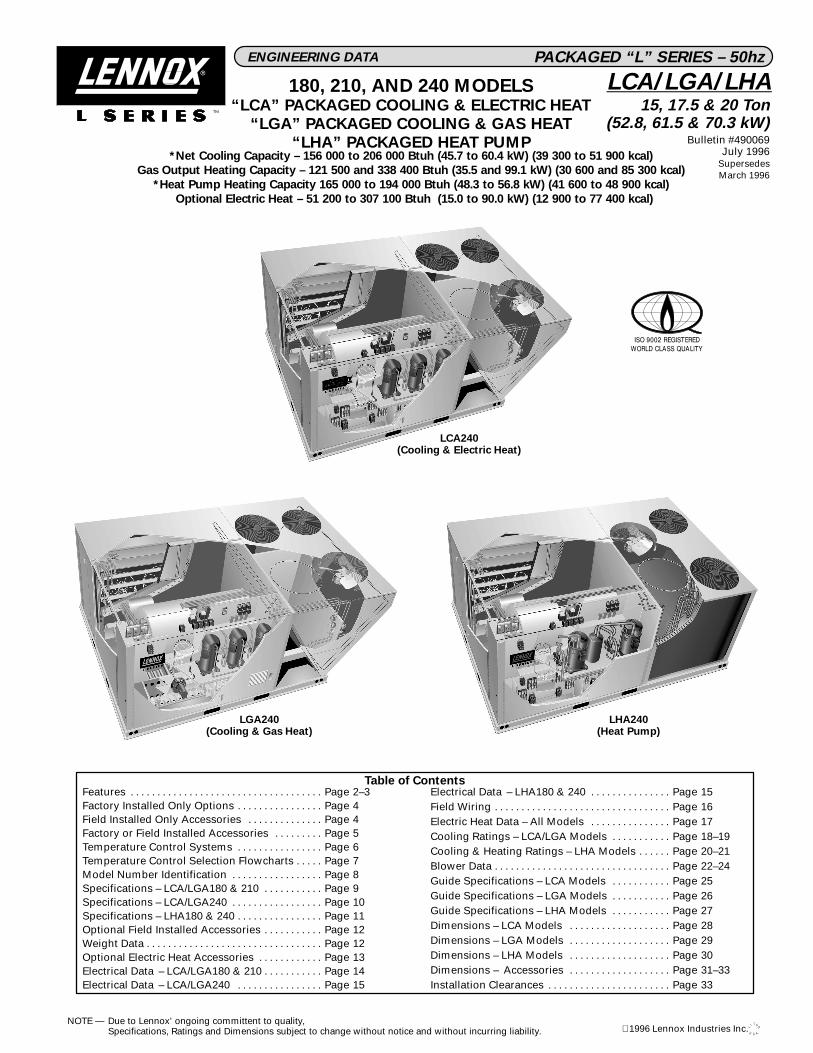
180, 210, AND 240 MODELS“LCA” PACKAGED COOLING & ELECTRIC HEAT
“LGA” PACKAGED COOLING & GAS HEAT
“LHA” PACKAGED HEAT PUMP*Net Cooling Capacity – 156 000 to 206 000 Btuh (45.7 to 60.4 kW) (39 300 to 51 900 kcal)
Gas Output Heating Capacity – 121 500 and 338 400 Btuh (35.5 and 99.1 kW) (30 600 and 85 300 kcal)
*Heat Pump Heating Capacity 165 000 to 194 000 Btuh (48.3 to 56.8 kW) (41 600 to 48 900 kcal)
Optional Electric Heat – 51 200 to 307 100 Btuh (15.0 to 90.0 kW) (12 900 to 77 400 kcal)
LCA240(Cooling & Electric Heat)
LGA240(Cooling & Gas Heat)
LHA240(Heat Pump)
Bulletin #490069July 1996
SupersedesMarch 1996
15, 17.5 & 20 Ton(52.8, 61.5 & 70.3 kW)
LCA/LGA/LHA
Table of ContentsFeatures Page 2–3. . . . . . . . . . . . . . . . . . . . . . . . . . . . . . . . . . . . Factory Installed Only Options Page 4. . . . . . . . . . . . . . . . Field Installed Only Accessories Page 4. . . . . . . . . . . . . . Factory or Field Installed Accessories Page 5. . . . . . . . . Temperature Control Systems Page 6. . . . . . . . . . . . . . . . Temperature Control Selection Flowcharts Page 7. . . . . Model Number Identification Page 8. . . . . . . . . . . . . . . . . Specifications – LCA/LGA180 & 210 Page 9. . . . . . . . . . . Specifications – LCA/LGA240 Page 10. . . . . . . . . . . . . . . . . Specifications – LHA180 & 240 Page 11. . . . . . . . . . . . . . . . Optional Field Installed Accessories Page 12. . . . . . . . . . . Weight Data Page 12. . . . . . . . . . . . . . . . . . . . . . . . . . . . . . . . . Optional Electric Heat Accessories Page 13. . . . . . . . . . . . Electrical Data – LCA/LGA180 & 210 Page 14. . . . . . . . . . . Electrical Data – LCA/LGA240 Page 15. . . . . . . . . . . . . . . .
Electrical Data – LHA180 & 240 Page 15. . . . . . . . . . . . . . . Field Wiring Page 16. . . . . . . . . . . . . . . . . . . . . . . . . . . . . . . . . Electric Heat Data – All Models Page 17. . . . . . . . . . . . . . . Cooling Ratings – LCA/LGA Models Page 18–19. . . . . . . . . . . Cooling & Heating Ratings – LHA Models Page 20–21. . . . . . Blower Data Page 22–24. . . . . . . . . . . . . . . . . . . . . . . . . . . . . . . . . Guide Specifications – LCA Models Page 25. . . . . . . . . . . Guide Specifications – LGA Models Page 26. . . . . . . . . . . Guide Specifications – LHA Models Page 27. . . . . . . . . . . Dimensions – LCA Models Page 28. . . . . . . . . . . . . . . . . . . Dimensions – LGA Models Page 29. . . . . . . . . . . . . . . . . . . Dimensions – LHA Models Page 30. . . . . . . . . . . . . . . . . . . Dimensions – Accessories Page 31–33. . . . . . . . . . . . . . . . . . . Installation Clearances Page 33. . . . . . . . . . . . . . . . . . . . . . .
PACKAGED “L” SERIES – 50hzENGINEERING DATA
�
NOTE — Due to Lennox’ ongoing committent to quality,Specifications, Ratings and Dimensions subject to change without notice and without incurring liability. 1996 Lennox Industries Inc.

FEATURES ALL MODELS
Item LCA/LGA/LHA180 LCA/LGA210 LCA/LGA/LHA240
Air Flow Choice — Bottom (down-flow) or �horizontal (side) supply and return air Standard Standard Standard
Bottom Power Electrical/Gas Entry Standard Standard Standard
Cabinet — Heavy gauge galvanized steel, fully insulated, powdered enamel paint fin-ish, large removeable access panels, electrical inlets in cabinet base and electricheat end panel (LCA/LHA only), easy access control area with factory installed con-trols, low voltage terminal strip, unit lifting holes in base rail
Standard Standard Standard
Cabinet Access Panels (Hinged) — 2 compressor/controls/heating area access panels,1 blower access panel and 1 air filter/economizer access panel hinged with tool-less access handles, gaskets on all edges for tight seal, access panels have steelpanel inner liner with insulation sandwiched in-between
Standard Standard Standard
Coil Construction — Copper tube construction, ripple-edged enhanced aluminumfins, flared shoulder tubing connections, silver soldered construction, factorytested, evaporator coil face split with separate circuits, indoor coil drain connec-tion extends outside of unit cabinet
Standard Standard Standard
Compressor Crankcase Heaters Standard Standard Standard
Filters — Disposable 2 inch (51 mm) pleated commercial grade Standard Standard Standard
Filter Access — Hinged filter door with tool-less access handles Standard Standard Standard
Integrated Modular Control (IMC) — Solid-state board contains all controls and con-trol relays to operate unitBuilt-in Functions Include:
– Blower On/Off Delay
– Built-in Control Parameter Defaults, ensure proper unit operation whenpower is restored after power failure
– Service Relay Output
– Defrost Control
– Dirty Filter Switch Input
– Economizer Control, four modes of operation (outdoor enthalpy, differentialenthalpy, temperature and global)
– Electric Heat Staging, regulates electric heat during building warm-up– ETM Compatible, various modules (see factory or field installed accessories)– Extensive Unit Diagnostics, (80 diagnostic codes)– Permanent Diagnostic Code Storage
– Field Changeable Control Parameters, (65 different parameters)– Gas Valve Delay Between First and Second Stage
– Indoor Air Quality Input, monitors CO2 levels, adjusts economizer dampersas needed (four modes of operation), requires optional field installed IndoorAir Quality (CO2) Sensor
– Low Ambient Controls — Allows unit cooling operation down to 0�F (–17.8�C)– Minimum Run Time
– Night Setback Mode, adjusts setpoint, closes outdoor air dampers andoperates blower on demand, may be customized for special requirements
– Smoke Alarm Mode, (four modes of operation)– “Strike Three” Low Pressure Control, protects system from low suction
pressure while eliminating nuisance faults– Thermostat Bounce Delay
– Three Digit Display, (Displays: outdoor temperature, supply air temperature,return air temperature, economizer damper position, Indoor Air Quality,control parameters
– Two Stage Thermostat Compatible
– Warm-up Mode, (four modes of operation)
Standard Standard Standard
Outdoor Coil Fans — Polyvinyl chloride (PVC) coated fan guards furnished Standard Standard Standard
Outdoor Coil Fan Motors — Overload protected, permanently lubricated, equippedwith ball bearings, shaft up, wire basket mount Standard Standard Standard
Supply Air Blower — Belt drive, forward curved blades with double inlet, blowerwheel statically and dynamically balanced, sleeve bearings, grease fittings fur-nished, adjustable pulley (allows speed change), blower assembly slides out ofunit for servicing
Standard Standard Standard
Supply Air Motor — Overload protected, equipped with ball bearings Standard Standard Standard
�With optional Horizontal Roof Mounting Frame.
— 2 —
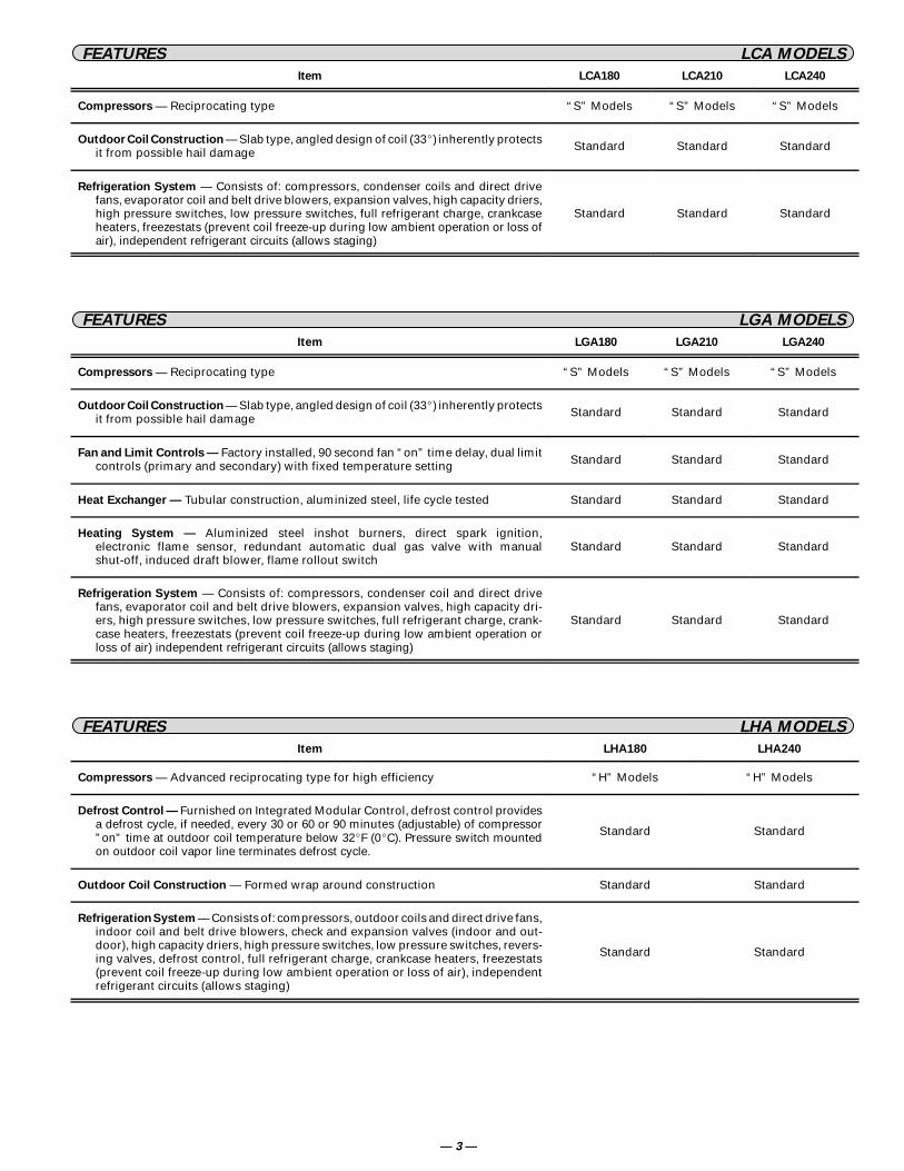
FEATURES LCA MODELS
Item LCA180 LCA210 LCA240
Compressors — Reciprocating type “S” Models “S” Models “S” Models
Outdoor Coil Construction — Slab type, angled design of coil (33�) inherently protectsit from possible hail damage Standard Standard Standard
Refrigeration System — Consists of: compressors, condenser coils and direct drivefans, evaporator coil and belt drive blowers, expansion valves, high capacity driers,high pressure switches, low pressure switches, full refrigerant charge, crankcaseheaters, freezestats (prevent coil freeze-up during low ambient operation or loss ofair), independent refrigerant circuits (allows staging)
Standard Standard Standard
FEATURES LGA MODELS
Item LGA180 LGA210 LGA240
Compressors — Reciprocating type “S” Models “S” Models “S” Models
Outdoor Coil Construction — Slab type, angled design of coil (33�) inherently protectsit from possible hail damage Standard Standard Standard
Fan and Limit Controls — Factory installed, 90 second fan “on” time delay, dual limitcontrols (primary and secondary) with fixed temperature setting Standard Standard Standard
Heat Exchanger — Tubular construction, aluminized steel, life cycle tested Standard Standard Standard
Heating System — Aluminized steel inshot burners, direct spark ignition,electronic flame sensor, redundant automatic dual gas valve with manualshut-off, induced draft blower, flame rollout switch
Standard Standard Standard
Refrigeration System — Consists of: compressors, condenser coil and direct drivefans, evaporator coil and belt drive blowers, expansion valves, high capacity dri-ers, high pressure switches, low pressure switches, full refrigerant charge, crank-case heaters, freezestats (prevent coil freeze-up during low ambient operation orloss of air) independent refrigerant circuits (allows staging)
Standard Standard Standard
FEATURES LHA MODELS
Item LHA180 LHA240
Compressors — Advanced reciprocating type for high efficiency “H” Models “H” Models
Defrost Control — Furnished on Integrated Modular Control, defrost control providesa defrost cycle, if needed, every 30 or 60 or 90 minutes (adjustable) of compressor”on” time at outdoor coil temperature below 32�F (0�C). Pressure switch mountedon outdoor coil vapor line terminates defrost cycle.
Standard Standard
Outdoor Coil Construction — Formed wrap around construction Standard Standard
Refrigeration System — Consists of: compressors, outdoor coils and direct drive fans,indoor coil and belt drive blowers, check and expansion valves (indoor and out-door), high capacity driers, high pressure switches, low pressure switches, revers-ing valves, defrost control, full refrigerant charge, crankcase heaters, freezestats(prevent coil freeze-up during low ambient operation or loss of air), independentrefrigerant circuits (allows staging)
Standard Standard
— 3 —
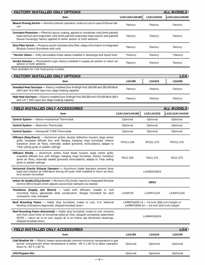
FACTORY INSTALLED ONLY OPTIONS ALL MODELS
Item LCA/LGA/LHA180 LCA/LGA210 LCA/LGA/LHA240
Blower Proving Switch — Monitors blower operation, locks out unit in case of blower fail-ure
Factory Factory Factory
Corrosion Protection — Phenolic epoxy coating, applied to condenser coils (with paintedbase section) and evaporator coils (with painted evaporator base section and paintedblower housings), factory applied to either section or both sections
Factory Factory Factory
Dirty Filter Switch — Pressure switch indicates dirty filter, relays information to IntegratedModule Control (furnished with unit)
Factory Factory Factory
*Service Valves — Fully serviceable brass valves installed in discharge and liquid lines *Factory Factory *Factory
Smoke Detector — Photoelectric type, factory installed in supply air section or return airsection or both sections Factory Factory Factory
*Not available for LHA heat pump models.
FACTORY INSTALLED ONLY OPTIONS LGA
Item LGA180 LGA210 LGA240
Standard Heat Gas Input — Factory installed (low fire/high fire) 169,000 and 260,000 Btuh(49.5 and 76.2 kW) input two stage heating capacity
Factory Factory Factory
High Heat Gas Input — Factory installed (low fire/high fire) 305,000 and 470,000 Btuh (89.4and 137.7 kW) input two stage heating capacity
Factory Factory Factory
FIELD INSTALLED ONLY ACCESSORIES ALL MODELS
Item LCA/LGA/LHA180 LCA/LGA210 LCA/LGA/LHA240
Control System — Electro-mechanical Thermostat Optional Optional Optional
Control System — Electronic Thermostat Optional Optional Optional
Control System — Honeywell T7300 Thermostat Optional Optional Optional
Diffusers (Step-Down) — Aluminum grilles, double deflection louvers, large centergrille, insulated diffuser box with flanges, hanging rings furnished, interiortransition (even air flow), internally sealed (prevents recirculation), adapts toT-bar ceiling grids or plaster ceilings
RTD11-185 RTD11-275 RTD11-275
Diffusers (Flush) — Aluminum grilles, fixed blade louvers, large center grille,insulated diffuser box with flanges, hanging rings furnished, interior transition(even air flow), internally sealed (prevents recirculation), adapts to T-bar ceilinggrids or plaster ceilings
FD11-185 FD11-275 FD11-275
Horizontal Gravity Exhaust Dampers — Aluminum blade dampers prevent blowback and outdoor air infiltration during off cycle, field installed in return air duct,bird screen furnished
LAGEDH18/24
Indoor Air Quality (CO2) Sensor — Monitors CO2 levels, reports to Integrated ModularControl (IMC) board which adjusts economizer dampers as needed
18K51
Transitions (Supply and Return) — Used with diffusers, installs in roofmounting frame, galvanized steel construction, flanges furnished for ductconnection, fully insulated
LASRT18 LASRT21/24 LASRT21/24
Roof Mounting Frame — Nailer strip furnished, mates to unit, U.S. NationalRoofing Contractors Approved, shipped knocked down
LARMF18/36-14 — 14 inch (356 mm) height orLARMF18/36-24 — 24 inch (610 mm) height
Roof Mounting Frame (Horizontal) — Nailer strip furnished, mates to unit, convertsunit from down-flow to horizontal (side) air flow, shipped completely assembledNOTE — return air is on unit, supply air is on frame, see dimension drawings,shipped knocked down
LARMFH18/24
FIELD INSTALLED ONLY ACCESSORIES LGA
Item LGA180 LGA210 LGA240
Cold Weather Kit — Electric heater automatically controls minimum temperature in gasburner compartment when temperature is below –40�C (–40�F) to allow operationdown to –50�C (–60�C)
Optional Optional Optional
LPG/Propane Kits Optional Optional Optional
— 4 —
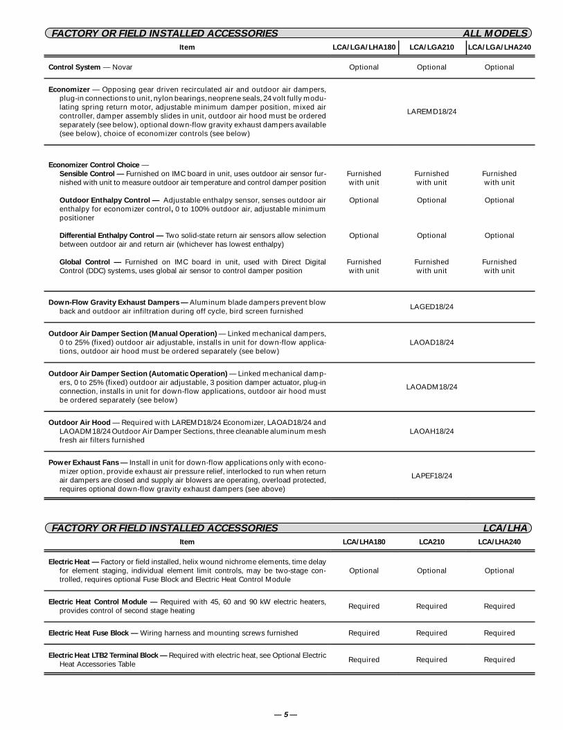
FACTORY OR FIELD INSTALLED ACCESSORIES ALL MODELS
Item LCA/LGA/LHA180 LCA/LGA210 LCA/LGA/LHA240
Control System — Novar Optional Optional Optional
Economizer — Opposing gear driven recirculated air and outdoor air dampers,plug-in connections to unit, nylon bearings, neoprene seals, 24 volt fully modu-lating spring return motor, adjustable minimum damper position, mixed aircontroller, damper assembly slides in unit, outdoor air hood must be orderedseparately (see below), optional down-flow gravity exhaust dampers available(see below), choice of economizer controls (see below)
LAREMD18/24
Economizer Control Choice —Sensible Control — Furnished on IMC board in unit, uses outdoor air sensor fur-nished with unit to measure outdoor air temperature and control damper position
Outdoor Enthalpy Control — Adjustable enthalpy sensor, senses outdoor airenthalpy for economizer control, 0 to 100% outdoor air, adjustable minimumpositioner
Differential Enthalpy Control — Two solid-state return air sensors allow selectionbetween outdoor air and return air (whichever has lowest enthalpy)
Global Control — Furnished on IMC board in unit, used with Direct DigitalControl (DDC) systems, uses global air sensor to control damper position
Furnishedwith unit
Optional
Optional
Furnishedwith unit
Furnishedwith unit
Optional
Optional
Furnishedwith unit
Furnishedwith unit
Optional
Optional
Furnishedwith unit
Down-Flow Gravity Exhaust Dampers — Aluminum blade dampers prevent blowback and outdoor air infiltration during off cycle, bird screen furnished
LAGED18/24
Outdoor Air Damper Section (Manual Operation) — Linked mechanical dampers,0 to 25% (fixed) outdoor air adjustable, installs in unit for down-flow applica-tions, outdoor air hood must be ordered separately (see below)
LAOAD18/24
Outdoor Air Damper Section (Automatic Operation) — Linked mechanical damp-ers, 0 to 25% (fixed) outdoor air adjustable, 3 position damper actuator, plug-inconnection, installs in unit for down-flow applications, outdoor air hood mustbe ordered separately (see below)
LAOADM18/24
Outdoor Air Hood — Required with LAREMD18/24 Economizer, LAOAD18/24 andLAOADM18/24 Outdoor Air Damper Sections, three cleanable aluminum meshfresh air filters furnished
LAOAH18/24
Power Exhaust Fans — Install in unit for down-flow applications only with econo-mizer option, provide exhaust air pressure relief, interlocked to run when returnair dampers are closed and supply air blowers are operating, overload protected,requires optional down-flow gravity exhaust dampers (see above)
LAPEF18/24
FACTORY OR FIELD INSTALLED ACCESSORIES LCA/LHA
Item LCA/LHA180 LCA210 LCA/LHA240
Electric Heat — Factory or field installed, helix wound nichrome elements, time delayfor element staging, individual element limit controls, may be two-stage con-trolled, requires optional Fuse Block and Electric Heat Control Module
Optional Optional Optional
Electric Heat Control Module — Required with 45, 60 and 90 kW electric heaters,provides control of second stage heating
Required Required Required
Electric Heat Fuse Block — Wiring harness and mounting screws furnished Required Required Required
Electric Heat LTB2 Terminal Block — Required with electric heat, see Optional ElectricHeat Accessories Table
Required Required Required
— 5 —

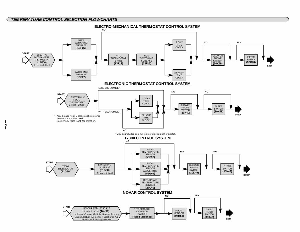
OPTIONAL TEMPERATURE CONTROL SYSTEMS (See Flow Charts on Page 7) ALL MODELS
System and Component Description Field Installed Catalog No.
ELECTRO-MECHANICAL THERMOSTAT CONTROL SYSTEM —
Thermostat — Two stage heat & two stage cool with dual temperature levers, subbase choice 13F06
Subbase — Manual system switch (Off-Heat-Auto-Cool), fan switch (Auto-On) 13F17
Subbase — Non-switching 13F16
Night Setback Operation — Order components below —
Heating Thermostat — Single stage heat 13F12
Subbase — Non-switching 13F16
Time Clock — 7 day operation, indicates day and night periods, 2 hour increments, battery back-up See Price Book for Selection
Time Clock — 24 hour night setback operation, 15 minute increments, battery back-up See Price Book for Selection
Dirty Filter Switch — Senses static pressure increase indicating a dirty filter condition 30K48
ELECTRONIC THERMOSTAT CONTROL SYSTEM —
Electronic Thermostat — Any two stage heat/ two stage cool electronic thermostat may be used See Price Book for Selection
Time Clock — 7 day operation, indicates day and night periods, 2 hour increments, battery back-up See Price Book for Selection
Time Clock — 24 hour night setback operation, 15 minute increments, battery back-up See Price Book for Selection
Dirty Filter Switch — Senses static pressure increase indicating a dirty filter condition 30K48
HONEYWELL T7300 THERMOSTAT CONTROL SYSTEM —
Thermostat — Programmable, internal or optional remote temperature sensing (sensorrequired), touch sensitive keyboard, automatic switching, �F or �C readout, no anticipator,droop/no droop selection, indicator LED’s, hour/day programming, override capabilities, timeand operational mode readout, stage status indicators, battery back-up, subbase choice
81G59
Subbase — Selectable staging up to two stage heat & two stage cool, manual system switch(Heat-Off-Auto-Cool), fan switch (Auto-On), indicator LED’s, auxiliary relay output foreconomizer operation
81G60
Sensor — Room temperature 58C92
Sensor — Room temperature with 3 hour override and setpoint adjustment 86G67
Sensor — Return air temperature 27C40
Dirty Filter Switch — Senses static pressure increase indicating a dirty filter condition 30K48
NOVAR ETM–2050 KIT —
Control Module/Blower Proving Switch/Return Air Sensor/Discharge Air Sensor/Wiring Har-ness — Control module monitors unit operation from different sensors installed in unit, hasoutputs for 2 stage heat/2 stage cool, automatic or continuous blower operation, economizerdamper operation and night setback, features: day/occupied mode with low enthalpy (out-door air damper open), high enthalpy (outdoor air damper closed) or night/unoccupied mode(outdoor air damper closed), network communication (RS–485, shielded pair twisted wire),local override (1 to 255 minutes), watchdog function, failsafe operation, ETM allows units tobe “daisy chained” together (up to 31 units) to be operated from one central location with an“executive” type control processor (onsite or offsite), built-in time delays, built-in unit operat-ing defaults, diagnostic LED’s indicate various operating functions, surge suppression pro-tects ETM against lightning or voltage spikes, Blower Proving Switch monitors blower opera-tion and locks out unit in case of blower failure, Return Air Sensor provides input to ETM mod-ule to determine heating or cooling operation and number of stages required, Discharge AirSensor monitors leaving air temperature during unit operation
16K91
Dirty Filter Switch — Senses static pressure increase indicating a dirty filter condition 30K48
Room Temperature Sensor — Provides input to ETM module to determine heating or coolingoperation and number of stages required (ordered separately) 97H53
Night Setback Override Switch — Allows momentary override of night setback duringunoccupied mode Field Furnished
— 6 —
TEMPERATURE CONTROL SELECTION FLOWCHARTS
NO
STOP
ELECTRO-MECHANICAL THERMOSTAT CONTROL SYSTEM
ELECTROMECHANICALTHERMOSTAT
(13F06)2 Heat – 2 Cool
START
NONSWITCHINGSUBBASE(13F16)
SWITCHINGSUBBASE(13F17)
NITETHERMOSTAT
1 Heat(13F12)
NONSWITCHINGSUBBASE(13F16)
24 HOURTIME
CLOCK
7 DAYTIME
CLOCK
NO NO
BLOWERPROVE
SWITCH(30K49)
FILTERSWITCH(30K48)
STOP
ELECTRONIC THERMOSTAT CONTROL SYSTEM
*ELECTRONICROOM
THERMOSTAT2 Heat – 2 Cool
START
�24 HOURTIME
CLOCK
�7 DAYTIME
CLOCK
NO NO
BLOWERPROVE
SWITCH(30K49)
FILTERSWITCH(30K48)
LESS ECONOMIZER
WITH ECONOMIZER
NO
* Any 2 stage heat/ 2 stage cool electronicthermostat may be used.See Lennox Price Book for selection.
�May be included as a function of electronic thermostat.
ROOMTEMPERATURE
SENSORW/OVERRIDE
(86G67)
NO
STOP
T7300 CONTROL SYSTEM
T7300THERMOSTAT
(81G59)
STARTSWITCHINGSUBBASE(81G60)
2 Heat – 2 Cool
NO NO
BLOWERPROVE
SWITCH(30K49)
FILTERSWITCH(30K48)
ROOMTEMPERATURE
SENSOR(58C92)
RETURN AIRTEMPERATURE
SENSOR(27C40)
STOP
START
ROOMSENSOR(97H53)
NO
DIRTYFILTER
SWITCH(30K48)
NO
NITE SETBACKOVERRIDESWITCH
(Field Furnished)
NOVAR ETM-2050 KIT2 Heat / 2 Cool (16K91)
Includes: Control Module, Blower ProvingSwitch, Return Air Sensor, Discharge Air
Sensor and Wiring Harness
NOVAR CONTROL SYSTEM
— 7
—
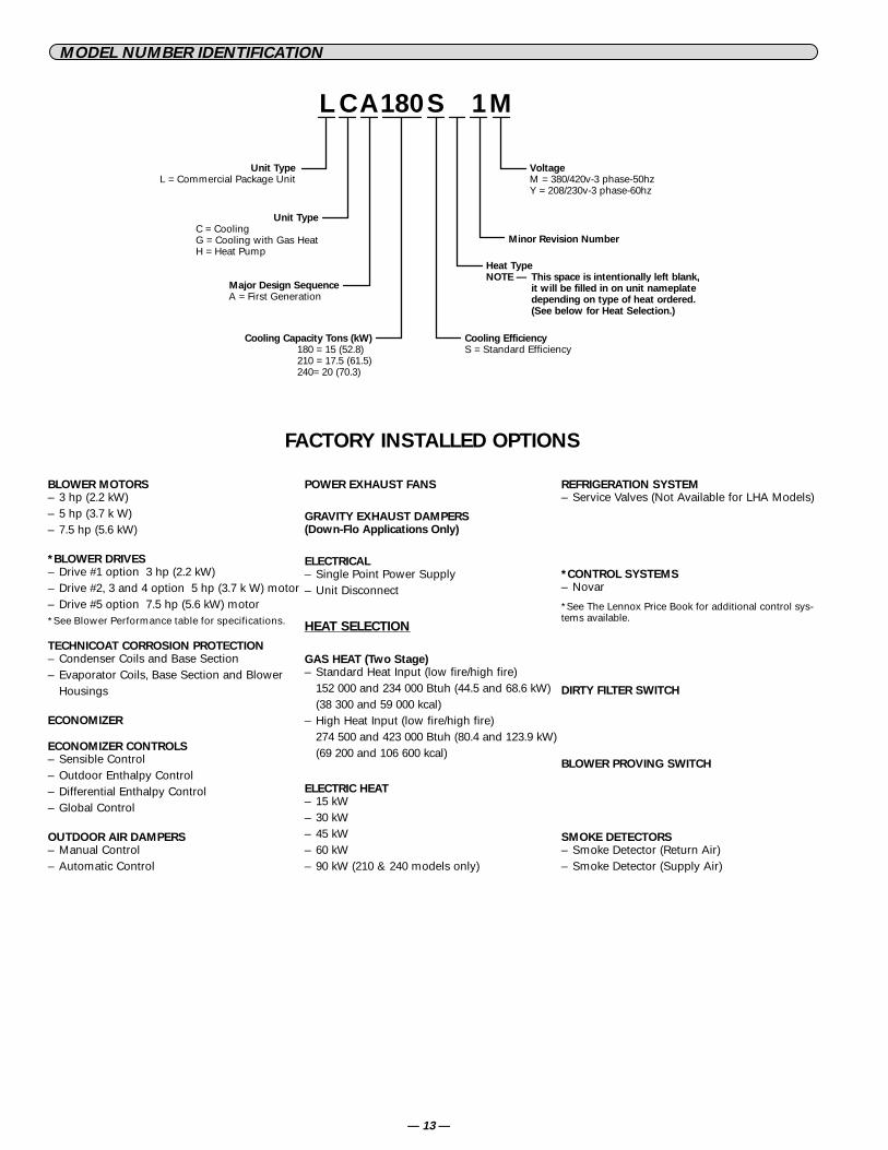
MODEL NUMBER IDENTIFICATION
Minor Revision Number
L CA M
Unit TypeL = Commercial Package Unit
Unit TypeC = CoolingG = Cooling with Gas HeatH = Heat Pump
Major Design SequenceA = First Generation
1180
Cooling Capacity Tons (kW)180 = 15 (52.8)210 = 17.5 (61.5)240= 20 (70.3)
S
Cooling EfficiencyS = Standard Efficiency
Heat TypeNOTE — This space is intentionally left blank,
it will be filled in on unit nameplatedepending on type of heat ordered.(See below for Heat Selection.)
VoltageM = 380/420v-3 phase-50hzY = 208/230v-3 phase-60hz
FACTORY INSTALLED OPTIONS
BLOWER MOTORS– 3 hp (2.2 kW)– 5 hp (3.7 k W)– 7.5 hp (5.6 kW)
*BLOWER DRIVES– Drive #1 option 3 hp (2.2 kW)– Drive #2, 3 and 4 option 5 hp (3.7 k W) motor– Drive #5 option 7.5 hp (5.6 kW) motor*See Blower Performance table for specifications.
TECHNICOAT CORROSION PROTECTION– Condenser Coils and Base Section– Evaporator Coils, Base Section and Blower
Housings
ECONOMIZER
ECONOMIZER CONTROLS– Sensible Control– Outdoor Enthalpy Control– Differential Enthalpy Control– Global Control
OUTDOOR AIR DAMPERS– Manual Control– Automatic Control
POWER EXHAUST FANS
GRAVITY EXHAUST DAMPERS(Down-Flo Applications Only)
ELECTRICAL– Single Point Power Supply– Unit Disconnect
HEAT SELECTION
GAS HEAT (Two Stage)– Standard Heat Input (low fire/high fire)
152 000 and 234 000 Btuh (44.5 and 68.6 kW)(38 300 and 59 000 kcal)
– High Heat Input (low fire/high fire)274 500 and 423 000 Btuh (80.4 and 123.9 kW)(69 200 and 106 600 kcal)
ELECTRIC HEAT– 15 kW– 30 kW– 45 kW– 60 kW– 90 kW (210 & 240 models only)
REFRIGERATION SYSTEM– Service Valves (Not Available for LHA Models)
*CONTROL SYSTEMS– Novar
*See The Lennox Price Book for additional control sys-tems available.
DIRTY FILTER SWITCH
BLOWER PROVING SWITCH
SMOKE DETECTORS– Smoke Detector (Return Air)– Smoke Detector (Supply Air)
— 13 —
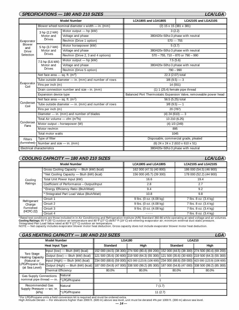
SPECIFICATIONS — 180 AND 210 SIZES LCA/LGA
Model Number LCA180S and LGA180S LCA210S and LGA210S
Blower wheel nominal diameter x width — in. (mm) (2) 15 x 15 (381 x 381)
3 hp (2.2 kW) Motor output — hp (kW) 3 (2.2)3 hp (2.2 kW)Motor and
D iVoltage and phase 380/420v-50hz-3 phase with neutral
EvaporatorBl
Drives Rev/min (Drive 1 option) 570 — 755Blower
and 5 hp (3.7 kW) Motor horsepower (kW) 5 (3.7)and
Drive5 hp (3.7 kW)
Motor andD i
Voltage and phase 380/420v-50hz-3 phase with neutralSelection Drives Rev/min (Drive 2, 3 and 4 options) 570 – 755, 710 – 870 or 790 – 990
7.5 hp (5.6 kW) Motor output — hp (kW) 7.5 (5.6)7.5 hp (5.6 kW)Motor and
D iVoltage and phase 380/420v-50hz-3 phase with neutral
Drives Rev/min (Drive 5 option) 790 – 990
Net face area — sq. ft. (m2) 22.3 (2.07) total
EvaporatorTube outside diameter — in. (mm) and number of rows 3/8 (9.5) — 3
EvaporatorCoil
Fins per inch (m) 14 (551)Coil
Drain connection number and size – in. (mm) (1) 1 (25.4) female pipe thread
Expansion device type Balanced Port Thermostatic Expansion Valve, removeable power head
CondenserNet face area — sq. ft. (m2) 56.5 (5.25) total
CondenserCoil
Tube outside diameter — in. (mm) and number of rows 3/8 (9.5) — 1Coil
Fins per inch (m) 20 (787)
Diameter — in. (mm) and number of blades (4) 24 (610) — 3
CondenserTotal Air volume — cfm (m3/s) 13 210 (6.25)
CondenserFans
Motor output – horsepower (W) (4) 1/3 (249)Fans
Motor rev/min 895
Total motor watts 1045
Filters( )
Type of filter Disposable, commercial grade, pleated(furnished) Number and size — in. (mm) (6) 24 x 24 x 2 (610 x 610 x 51)
Electrical characteristics 380/420v-50hz-3 phase with neutral
COOLING CAPACITY — 180 AND 210 SIZES LCA/LGA
Model Number LCA180S and LGA180S LCA210S and LGA210S
Gross Cooling Capacity — Btuh (kW) (kcal) 162 000 (47.5) (40 800) 186 000 (54.5) (46 900)
*Net Cooling Capacity — Btuh (kW) (kcal) 156 000 (45.7) (39 300) 178 000 (52.2) (44 900)
Cooling Total Unit Power Input (kW) 16.6 19.4gRatings Coefficient of Performance – Output/Input 2.8 2.7
*Energy Efficiency Ratio (Btuh/Watt) 9.4 9.2
*�Integrated Part Load Value (Btuh/Watt) 10.8 9.8
RefrigerantCircuit 1 9 lbs. (0 oz. (4.08 kg) 7 lbs. 8 oz. (3.4 kg)
RefrigerantCharge Circuit 2 9 lbs. (0 oz. (4.08 kg) 7 lbs. 8 oz. (3.4 kg)g
Furnished(HCFC 22)
Circuit 3 9 lbs. (0 oz. (4.08 kg) 7 lbs. 8 oz. (3.4 kg)(HCFC-22)
Circuit 4 - - - - 7 lbs. 8 oz. (3.4 kg)*Rated test conditions are those included in in Air Conditioning and Refrigeration Institute (ARI) Standard 360-86 while operating at rated voltage and air volumes.Cooling Ratings: 95�F (35�C) outdoor air temperature and 80�F (27�C) db/67�F (19�C) wb entering evaporator air; minimum external duct static pressure.�Integrated Part Load Value rated at 80�F (27�C) outdoor air temperature.NOTE — Net capacity includes evaporator blower motor heat deduction. Gross capacity does not include evaporator blower motor heat deduction.
GAS HEATING CAPACITY — 180 AND 210 SIZES LGAModel Number LGA180 LGA210
Heat Input Type Standard High Standard High
Two StageInput (low) — Btuh (kW) (kcal) 152 000 (44.5) (38 300) 274 500 (80.4) (69 200) 152 000 (44.5) (38 300) 274 500 (80.4) (69 200)
Two StageHeating Capacity Output (low) — Btuh (kW) (kcal) 121 500 (35.6) (30 600) 219 500 (64.3) (55 300) 121 500 (35.6) (30 600) 219 500 (64.3) (55 300)Heating Capacity
(Natural orLPG/P G
Input (High) — Btuh (kW) (kcal) 234 000 (68.6) (59 000) 423 000 (123.9) (106 600) 234 000 (68.6) (59 000) 423 000 (123.9) (106 600)LPG/Propane Gas
(at Sea Level)Output (High) — Btuh (kW) (kcal) 187 000 (54.8) (47 000) 338 500 (99.2) (85 300) 187 000 (54.8) (47 000) 338 500 (99.2) (85 300)
(at Sea Level)Thermal Efficiency 80.0% 80.0% 80.0% 80.0%
Gas Supply Connections Natural 1nominal pipe thread — in. *LPG/Propane 1
Recommended GasSupply Pressure — wc in
Natural 7 (1.7)Supply Pressure — wc. in.
(kPa) *LPG/Propane 11 (2.7)
*For LPG/Propane units a field conversion kit is required and must be ordered extra.High Altitude Derate — For elevations higher than 2000 ft. (600 m) above sea level, unit must be derated 4% per 1000 ft. (300 m) above sea level.
— 14 —
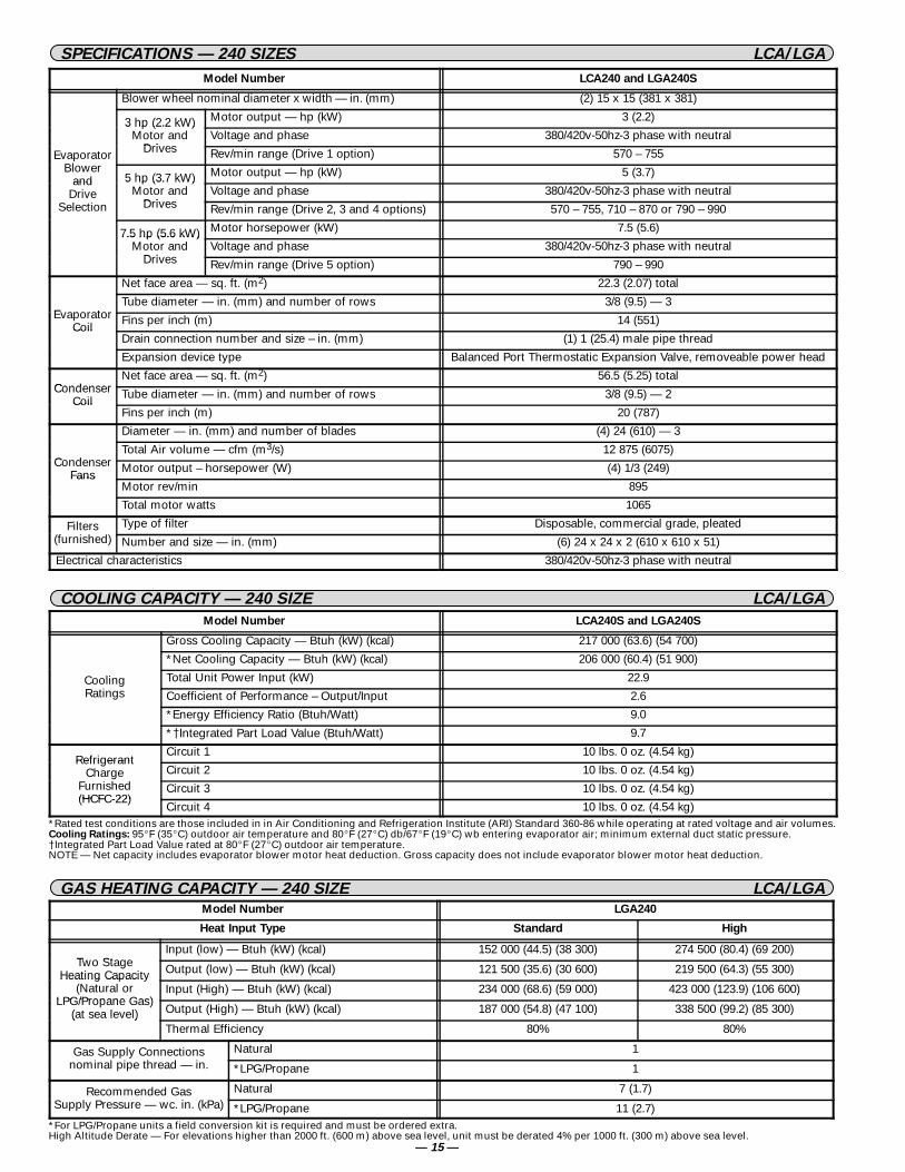
SPECIFICATIONS — 240 SIZES LCA/LGA
Model Number LCA240 and LGA240S
Blower wheel nominal diameter x width — in. (mm) (2) 15 x 15 (381 x 381)
3 hp (2.2 kW) Motor output — hp (kW) 3 (2.2)3 hp (2.2 kW)Motor and
D iVoltage and phase 380/420v-50hz-3 phase with neutral
EvaporatorBl
Drives Rev/min range (Drive 1 option) 570 – 755Blower
and 5 hp (3.7 kW) Motor output — hp (kW) 5 (3.7)and
Drive5 hp (3.7 kW)
Motor andD i
Voltage and phase 380/420v-50hz-3 phase with neutralSelection Drives Rev/min range (Drive 2, 3 and 4 options) 570 – 755, 710 – 870 or 790 – 990
7.5 hp (5.6 kW) Motor horsepower (kW) 7.5 (5.6)7.5 hp (5.6 kW)Motor and
D iVoltage and phase 380/420v-50hz-3 phase with neutral
Drives Rev/min range (Drive 5 option) 790 – 990
Net face area — sq. ft. (m2) 22.3 (2.07) total
EvaporatorTube diameter — in. (mm) and number of rows 3/8 (9.5) — 3
EvaporatorCoil
Fins per inch (m) 14 (551)Coil
Drain connection number and size – in. (mm) (1) 1 (25.4) male pipe thread
Expansion device type Balanced Port Thermostatic Expansion Valve, removeable power head
CondenserNet face area — sq. ft. (m2) 56.5 (5.25) total
CondenserCoil
Tube diameter — in. (mm) and number of rows 3/8 (9.5) — 2Coil
Fins per inch (m) 20 (787)
Diameter — in. (mm) and number of blades (4) 24 (610) — 3
CondenserTotal Air volume — cfm (m3/s) 12 875 (6075)
CondenserFans
Motor output – horsepower (W) (4) 1/3 (249)Fans
Motor rev/min 895
Total motor watts 1065
Filters( )
Type of filter Disposable, commercial grade, pleated(furnished) Number and size — in. (mm) (6) 24 x 24 x 2 (610 x 610 x 51)
Electrical characteristics 380/420v-50hz-3 phase with neutral
COOLING CAPACITY — 240 SIZE LCA/LGA
Model Number LCA240S and LGA240S
Gross Cooling Capacity — Btuh (kW) (kcal) 217 000 (63.6) (54 700)
*Net Cooling Capacity — Btuh (kW) (kcal) 206 000 (60.4) (51 900)
Cooling Total Unit Power Input (kW) 22.9gRatings Coefficient of Performance – Output/Input 2.6
*Energy Efficiency Ratio (Btuh/Watt) 9.0
*�Integrated Part Load Value (Btuh/Watt) 9.7
RefrigerantCircuit 1 10 lbs. 0 oz. (4.54 kg)
RefrigerantCharge Circuit 2 10 lbs. 0 oz. (4.54 kg)g
Furnished(HCFC 22)
Circuit 3 10 lbs. 0 oz. (4.54 kg)(HCFC-22)
Circuit 4 10 lbs. 0 oz. (4.54 kg)*Rated test conditions are those included in in Air Conditioning and Refrigeration Institute (ARI) Standard 360-86 while operating at rated voltage and air volumes.Cooling Ratings: 95�F (35�C) outdoor air temperature and 80�F (27�C) db/67�F (19�C) wb entering evaporator air; minimum external duct static pressure.�Integrated Part Load Value rated at 80�F (27�C) outdoor air temperature.NOTE — Net capacity includes evaporator blower motor heat deduction. Gross capacity does not include evaporator blower motor heat deduction.
GAS HEATING CAPACITY — 240 SIZE LCA/LGAModel Number LGA240
Heat Input Type Standard High
T o StageInput (low) — Btuh (kW) (kcal) 152 000 (44.5) (38 300) 274 500 (80.4) (69 200)
Two StageHeating Capacity Output (low) — Btuh (kW) (kcal) 121 500 (35.6) (30 600) 219 500 (64.3) (55 300)Heating Capacity
(Natural orLPG/Propane Gas)
Input (High) — Btuh (kW) (kcal) 234 000 (68.6) (59 000) 423 000 (123.9) (106 600)LPG/Propane Gas)
(at sea level) Output (High) — Btuh (kW) (kcal) 187 000 (54.8) (47 100) 338 500 (99.2) (85 300)(a sea e e )Thermal Efficiency 80% 80%
Gas Supply Connections Natural 1nominal pipe thread — in. *LPG/Propane 1
Recommended Gas( )
Natural 7 (1.7)Supply Pressure — wc. in. (kPa) *LPG/Propane 11 (2.7)
*For LPG/Propane units a field conversion kit is required and must be ordered extra.High Altitude Derate — For elevations higher than 2000 ft. (600 m) above sea level, unit must be derated 4% per 1000 ft. (300 m) above sea level.
— 15 —
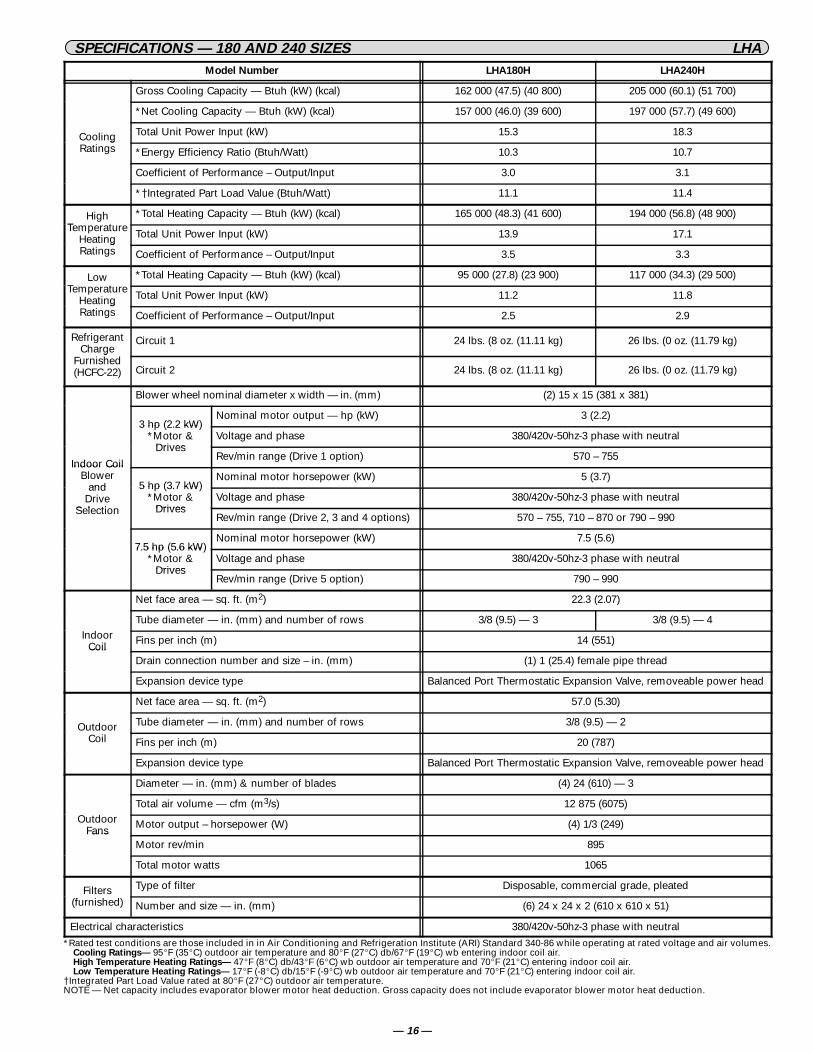
SPECIFICATIONS — 180 AND 240 SIZES LHA
Model Number LHA180H LHA240H
Gross Cooling Capacity — Btuh (kW) (kcal) 162 000 (47.5) (40 800) 205 000 (60.1) (51 700)
*Net Cooling Capacity — Btuh (kW) (kcal) 157 000 (46.0) (39 600) 197 000 (57.7) (49 600)
Cooling Total Unit Power Input (kW) 15.3 18.3gRatings *Energy Efficiency Ratio (Btuh/Watt) 10.3 10.7
Coefficient of Performance – Output/Input 3.0 3.1
*�Integrated Part Load Value (Btuh/Watt) 11.1 11.4
HighT t
*Total Heating Capacity — Btuh (kW) (kcal) 165 000 (48.3) (41 600) 194 000 (56.8) (48 900)Temperature
Heating Total Unit Power Input (kW) 13.9 17.1gRatings Coefficient of Performance – Output/Input 3.5 3.3
LowT t
*Total Heating Capacity — Btuh (kW) (kcal) 95 000 (27.8) (23 900) 117 000 (34.3) (29 500)Temperature
Heating Total Unit Power Input (kW) 11.2 11.8gRatings Coefficient of Performance – Output/Input 2.5 2.9
RefrigerantCharge
Circuit 1 24 lbs. (8 oz. (11.11 kg) 26 lbs. (0 oz. (11.79 kg)g
Furnished(HCFC-22) Circuit 2 24 lbs. (8 oz. (11.11 kg) 26 lbs. (0 oz. (11.79 kg)
Blower wheel nominal diameter x width — in. (mm) (2) 15 x 15 (381 x 381)
3 hp (2 2 kW)Nominal motor output — hp (kW) 3 (2.2)
3 hp (2.2 kW)*Motor &
DrivesVoltage and phase 380/420v-50hz-3 phase with neutral
Indoor Coil
DrivesRev/min range (Drive 1 option) 570 – 755
Indoor CoilBlower
and 5 hp (3 7 kW)Nominal motor horsepower (kW) 5 (3.7)
andDrive
S l ti
5 hp (3.7 kW)*Motor &
DrivesVoltage and phase 380/420v-50hz-3 phase with neutral
Selection DrivesRev/min range (Drive 2, 3 and 4 options) 570 – 755, 710 – 870 or 790 – 990
7 5 hp (5 6 kW)Nominal motor horsepower (kW) 7.5 (5.6)
7.5 hp (5.6 kW)*Motor &
DrivesVoltage and phase 380/420v-50hz-3 phase with neutral
DrivesRev/min range (Drive 5 option) 790 – 990
Net face area — sq. ft. (m2) 22.3 (2.07)
Tube diameter — in. (mm) and number of rows 3/8 (9.5) — 3 3/8 (9.5) — 4Indoor
CoilFins per inch (m) 14 (551)
CoilDrain connection number and size – in. (mm) (1) 1 (25.4) female pipe thread
Expansion device type Balanced Port Thermostatic Expansion Valve, removeable power head
Net face area — sq. ft. (m2) 57.0 (5.30)
Outdoor Tube diameter — in. (mm) and number of rows 3/8 (9.5) — 2
Coil Fins per inch (m) 20 (787)
Expansion device type Balanced Port Thermostatic Expansion Valve, removeable power head
Diameter — in. (mm) & number of blades (4) 24 (610) — 3
Total air volume — cfm (m3/s) 12 875 (6075)Outdoor
FansMotor output – horsepower (W) (4) 1/3 (249)
FansMotor rev/min 895
Total motor watts 1065
Filters Type of filter Disposable, commercial grade, pleated
(furnished) Number and size — in. (mm) (6) 24 x 24 x 2 (610 x 610 x 51)
Electrical characteristics 380/420v-50hz-3 phase with neutral
*Rated test conditions are those included in in Air Conditioning and Refrigeration Institute (ARI) Standard 340-86 while operating at rated voltage and air volumes.Cooling Ratings— 95�F (35�C) outdoor air temperature and 80�F (27�C) db/67�F (19�C) wb entering indoor coil air.High Temperature Heating Ratings— 47�F (8�C) db/43�F (6�C) wb outdoor air temperature and 70�F (21�C) entering indoor coil air.Low Temperature Heating Ratings— 17�F (-8�C) db/15�F (-9�C) wb outdoor air temperature and 70�F (21�C) entering indoor coil air.
�Integrated Part Load Value rated at 80�F (27�C) outdoor air temperature.NOTE — Net capacity includes evaporator blower motor heat deduction. Gross capacity does not include evaporator blower motor heat deduction.
— 16 —

OPTIONAL FIELD INSTALLED ACCESSORIES ALL MODELS
Unit Model Number LCA/LGA/LHA180 LCA/LGA210 and LCA/LGA/LHA240
LPG/Propane Conversion Kit (LGA models only) 19K52 (2 kits required)
Down-FlowRoof Mounting Frame
14 inch (356 mm) height LARMF18/36-14 (160 lbs.) (73 kg) (16K87)Roof Mounting Frame
(Net Weight) 24 inch (610 mm) height LARMF18/36-24 (220 lbs.) (100 kg) (16K88)
Horizontal Roof Mounting Frame — (Net Weight) LARMFH18/24 (300 lbs.) (136 kg) (97J33)
Economizer(Outdoor Air Hood
Required – Order Separately)Model Number — (Net Weight) LAREMD18/24 (73 lbs.) (33 kg) (16K95)
Outdoor Air Hood — (Net Weight)Number, size and type of filters — in. (mm)
LAOAH18/24 (19K37) (45 lbs.) (20 kg) required with Economizer(3) 16 x 25 x 1 (406 x 635 x 25) aluminum mesh
Outdoor Enthalpy Control 16K96
Differential Enthalpy Control 16K97
Gravity Exhaust Dampers(R i d Wi h E i )
Down-Flow — (Net Weight) LAGED18/24 (20 lbs.) (9 kg) (16K98)
(Required With Economizer) *Horizontal — (Net Weight) LAGEDH18/24 (16 lbs.) (7 kg) (16K99)
Power ExhaustFans
Model Number (Net Weight) LAPEF18/24 (66 lbs.) (30 kg) (25K68)Fans
(Down-Flo Only)(A il bl With
Diameter — in. (mm) & number of blades (2) 20 (508) — 5(Available With
Economizer Only, Total air volume — cfm (m3/s 7190 (3.4) @ 0 in. w.g. (0 Pa)y,Down-flow
Gravity ExhaustMotor output – horsepower (W) (2) 1/3 (249)
Gravity ExhaustDampers Required) Total watts input 575
Ceiling Supply and Step-Down RTD11-185 (392 lbs.) (178 kg) (29G06) RTD11-275 (403 lbs.) (183 kg) (29G07)Ceiling Supply andReturn Air Diffusers
(Net Weight)Flush FD11-185 (289 lbs.) (131 kg) (29G10) FD11-275 (363 lbs.) (165 kg) (29G11)
(Net Weight) Transition LASRT18 (80 lbs.) (36 kg) (19K01) LASRT21/24 (75 lbs.) (34 kg) (19K02)
Outdoor Air Damper (Manual Operation) — (Net Weight)(Outdoor Air Hood Required – Order Separately) LAOAD18/24 (40 lbs.) (18 kg) (16K93)
Outdoor Air Damper (Automatic Operation) — (Net Weight)(Outdoor Air Hood Required – Order Separately) LAOADM18/24 (45 lbs.) (20 kg) (16K94)
Outdoor Air Hood — (Net Weight)Number, size and type of filters — in. (mm)
LAOAH18/24 (19K37) (45 lbs.) (20 kg) required with Outdoor Air Damper(3) 16 x 25 x 1 (406 x 635 x 25) aluminum mesh
Indoor Air Quality (CO2) Sensor 18K51
*Field installs in return air duct. Two dampers furnished per order number.
WEIGHT DATA ALL MODELS
Model Number DescriptionWeight
Model Number Descriptionlbs. kg
Net Weights
LCA180S Net weight (Base unit) 2200 1000
LCA210S Net weight (Base unit) 2285 1035
LCA240S Net weight (Base unit) 2415 1095
LGA180S Net weight (Base unit with low fire heat exchanger) 2255 1025
LGA210S Net weight (Base unit with low fire heat exchanger) 2340 1060
LGA240S Net weight (Base unit with low fire heat exchanger) 2470 1120
LHA180H Net weight (Base unit) 2355 1070
LHA240H Net weight (Base unit) 2400 1090
Shipping Weights (Add Factory Installed Options Weights To Base Unit Weights For Total Shipping Weight)
LCA180S Base unit 2485 1125
LCA210S Base unit 2570 1165
LCA240S Base unit 2700 1225
LHA180H Base unit 2655 1205
LHA240H Base unit 2700 1225
LCA/LHAModels Only Electric Heat (add to Base unit) See Electric Heat Rating Tables
LGA180S Base unit with low fire heat exchanger 2540 1150
LGA210S Base unit with low fire heat exchanger 2625 1190
LGA240S Base unit with low fire heat exchanger 2755 1250
LGAModels Only High Fire Heat Exchanger (add to Base unit) 30 14
Economizer (add to Base unit) 73 33
All Models Outdoor Air Damper (add to Base unit) 45 20
Power Exhaust (add to Base unit) 62 19
— 17 —

OPTIONAL ELECTRIC HEAT ACCESSORIES LCA/LHA
ELECTRIC HEAT CONTROL MODULE AND UNIT FUSE BLOCKS
Unit Model Number LCA180S LCA210S LCA240S LHA180H LHA240H
ElectricModel Number EHA (see Electric Heat Data tables for additional information)
ElectricHeat
kW Input Range 15–30–45–60 15–30–45–60–90 15–30–45–60–90 15–30–45–60 15–30–45–60–90
Electric Heat Control Module (45, 60 and 90 kW) 37K11
Without
3 hp (2.2 kW) 25K11 25K11 25K13 25K10 25K13
WithoutPower
ExhaustFans
5 hp (3.7 kW) 25K11 25K13 25K13 25K11 25K13
UnitFuse
Fans
7.5 hp (5.6 kW) 25K13 25K13 25K14 25K13 25K14FuseBlock
(3 phase)
With
3 hp (2.2 kW) 25K11 25K12 25K13 25K11 25K13
WithPower
ExhaustFans
5 hp (3.7 kW) 25K13 25K13 25K14 25K11 25K14
Fans
7.5 hp (5.6 kW) 25K13 25K13 25K14 25K13 25K14
LTB2 ELECTRIC HEAT TERMINAL BLOCKLTB2-175 (30K75) 175 amps, LBT2-335 (30K76) 335 amps
(Required For Units Without Disconnect/Circuit Breaker But With Single Point Power Source)
Unit Model Number LCA180S LCA210S LCA240S LHA180H LHA240H
3 hp (2.2 kW) 30K75 30K75 30K75 30K75 30K75
12 kW 5 hp (3.7 kW) 30K75 30K75 30K75 30K75 30K75
7.5 hp (5.6 kW) 30K75 30K75 30K75 30K75 30K75
3 hp (2.2 kW) 30K75 30K75 30K75 30K75 30K76
25 kW 5 hp (3.7 kW) 30K75 30K75 30K75 30K75 30K76
7.5 hp (5.6 kW) 30K75 30K75 30K75 30K76 30K76
LTB2Terminal
3 hp (2.2 kW) 30K75 30K75 30K75 30K76 30K76
TerminalBlock
(3 phase) 35 kW 5 hp (3.7 kW) 30K75 30K75 30K75 30K76 30K76
7.5 hp (5.6 kW) 30K75 30K75 30K75 30K76 30K76
3 hp (2.2 kW) 30K75 30K75 30K75 30K76 30K76
45 kW 5 hp (3.7 kW) 30K75 30K75 30K75 30K76 30K76
7.5 hp (5.6 kW) 30K76 30K76 30K76 30K76 30K76
3 hp (2.2 kW) 30K76 30K76 30K76 30K76 30K76
70 kW 5 hp (3.7 kW) 30K76 30K76 30K76 30K76 30K76
7.5 hp (5.6 kW) 30K76 30K76 30K76 30K76 30K76
NOTE — Terminal Block is factory installed in units with factory installed electric heat without disconnect/circuit breaker but with single pointpower source.
— 18 —
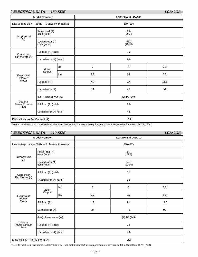
ELECTRICAL DATA — 180 SIZE LCA/LGA
Model Number LCA180 and LGA180
Line voltage data — 50 Hz — 3 phase with neutral 380/420V
Compressors
Rated load (A)each (total)
8.6(25.8)
Compressors(3)
Locked rotor (A)each (total)
55.0(165.0)
CondenserFull load (A) (total) 7.2
CondenserFan Motors (4)
Locked rotor (A) (total) 9.6
Motorhp 3 5 7.5
EvaporatorBlower
MotorOutput
kW 2.2 3.7 5.6BlowerMotor Full load (A) 4.7 7.4 11.6
Locked rotor (A) 27 41 92
(No.) Horsepower (W) (2) 1/3 (249)
OptionalPower Exhaust
FansFull load (A) (total) 2.6
Fans
Locked rotor (A) (total) 4.8
Electric Heat — Per Element (A) 15.7
*Refer to local electrical codes to determine wire, fuse and disconnect size requirements. Use wires suitable for at least 167�F (75�C).
ELECTRICAL DATA — 210 SIZE LCA/LGA
Model Number LCA210 and LGA210
Line voltage data — 50 Hz — 3 phase with neutral 380/420V
Compressors
Rated load (A)each (total)
5.7(22.8)
Compressors(4)
Locked rotor (A)each (total)
52.5(210.0)
CondenserFull load (A) (total) 7.2
CondenserFan Motors (4)
Locked rotor (A) (total) 9.6
Motorhp 3 5 7.5
EvaporatorBlower
MotorOutput
kW 2.2 3.7 5.6BlowerMotor Full load (A) 4.7 7.4 11.6
Locked rotor (A) 27 41 92
(No.) Horsepower (W) (2) 1/3 (249)
OptionalPower Exhaust
FansFull load (A) (total) 2.6
Fans
Locked rotor (A) (total) 4.8
Electric Heat — Per Element (A) 15.7
*Refer to local electrical codes to determine wire, fuse and disconnect size requirements. Use wires suitable for at least 167�F (75�C).
— 19 —
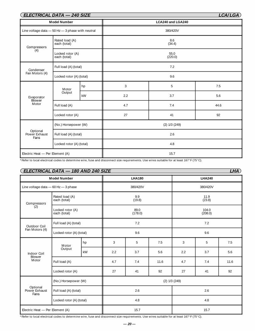
ELECTRICAL DATA — 240 SIZE LCA/LGA
Model Number LCA240 and LGA240
Line voltage data — 50 Hz — 3 phase with neutral 380/420V
Compressors
Rated load (A)each (total)
8.6(34.4)
Compressors(4)
Locked rotor (A)each (total)
55.0(220.0)
CondenserFull load (A) (total) 7.2
CondenserFan Motors (4)
Locked rotor (A) (total) 9.6
Motorhp 3 5 7.5
EvaporatorBlower
MotorOutput
kW 2.2 3.7 5.6BlowerMotor Full load (A) 4.7 7.4 44.6
Locked rotor (A) 27 41 92
(No.) Horsepower (W) (2) 1/3 (249)
OptionalPower Exhaust
FansFull load (A) (total) 2.6
Fans
Locked rotor (A) (total) 4.8
Electric Heat — Per Element (A) 15.7
*Refer to local electrical codes to determine wire, fuse and disconnect size requirements. Use wires suitable for at least 167�F (75�C).
ELECTRICAL DATA — 180 AND 240 SIZE LHA
Model Number LHA180 LHA240
Line voltage data — 60 Hz — 3 phase 380/420V 380/420V
Compressors
Rated load (A)each (total)
9.9(19.8)
11.9(23.8)
Compressors(2)
Locked rotor (A)each (total)
89.0(178.0)
104.0(208.0)
Outdoor CoilFull load (A) (total) 7.2 7.2
Outdoor CoilFan Motors (4)
Locked rotor (A) (total) 9.6 9.6
Motorhp 3 5 7.5 3 5 7.5
Indoor CoilBlower
MotorOutput
kW 2.2 3.7 5.6 2.2 3.7 5.6BlowerMotor Full load (A) 4.7 7.4 11.6 4.7 7.4 11.6
Locked rotor (A) 27 41 92 27 41 92
(No.) Horsepower (W) (2) 1/3 (249)
OptionalPower Exhaust
FansFull load (A) (total) 2.6 2.6
Fans
Locked rotor (A) (total) 4.8 4.8
Electric Heat — Per Element (A) 15.7 15.7
*Refer to local electrical codes to determine wire, fuse and disconnect size requirements. Use wires suitable for at least 167�F (75�C).
— 20 —
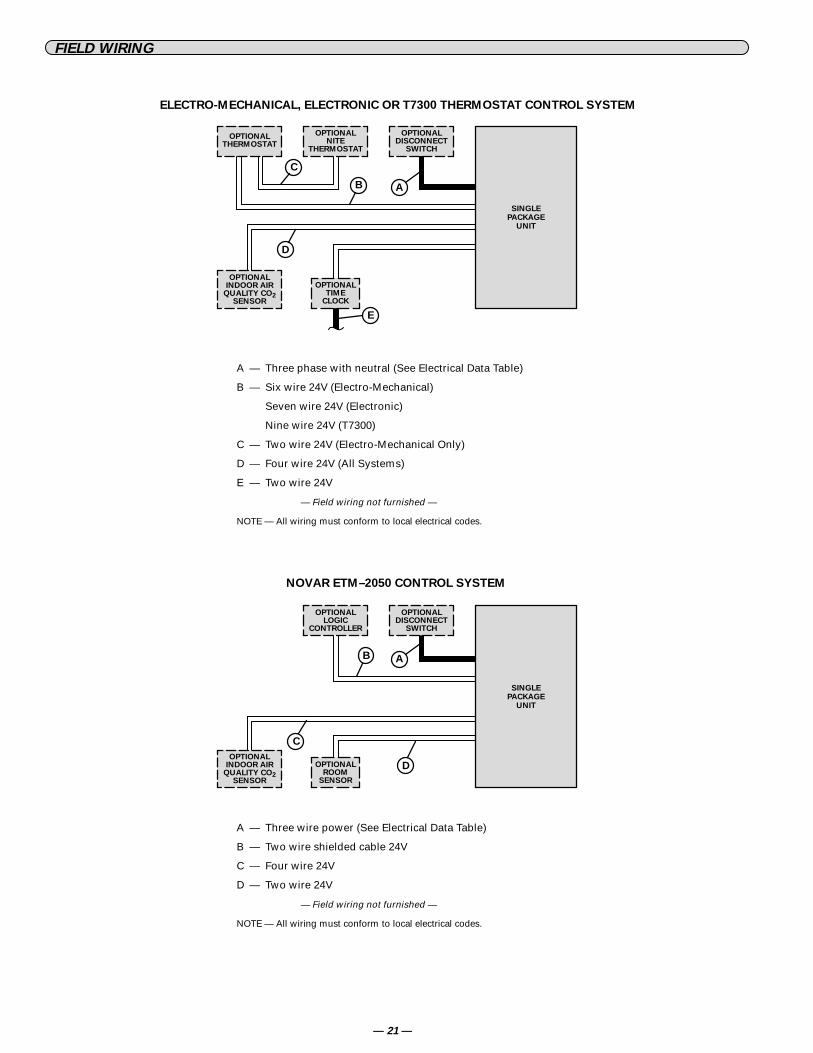
FIELD WIRING
ELECTRO-MECHANICAL, ELECTRONIC OR T7300 THERMOSTAT CONTROL SYSTEM
NOVAR ETM–2050 CONTROL SYSTEM
OPTIONALTHERMOSTAT
OPTIONALNITE
THERMOSTAT
OPTIONALDISCONNECT
SWITCH
OPTIONALTIME
CLOCK
OPTIONALINDOOR AIR
QUALITY CO2SENSOR
SINGLEPACKAGE
UNIT
OPTIONALLOGIC
CONTROLLER
OPTIONALDISCONNECT
SWITCH
OPTIONALROOM
SENSOR
SINGLEPACKAGE
UNIT
A — Three phase with neutral (See Electrical Data Table)
B — Six wire 24V (Electro-Mechanical)
Seven wire 24V (Electronic)
Nine wire 24V (T7300)
C — Two wire 24V (Electro-Mechanical Only)
D — Four wire 24V (All Systems)
E — Two wire 24V
— Field wiring not furnished —
NOTE — All wiring must conform to local electrical codes.
AB
C
E
D
AB
C
D
A — Three wire power (See Electrical Data Table)
B — Two wire shielded cable 24V
C — Four wire 24V
D — Two wire 24V
— Field wiring not furnished —
NOTE — All wiring must conform to local electrical codes.
OPTIONALINDOOR AIR
QUALITY CO2SENSOR
— 21 —
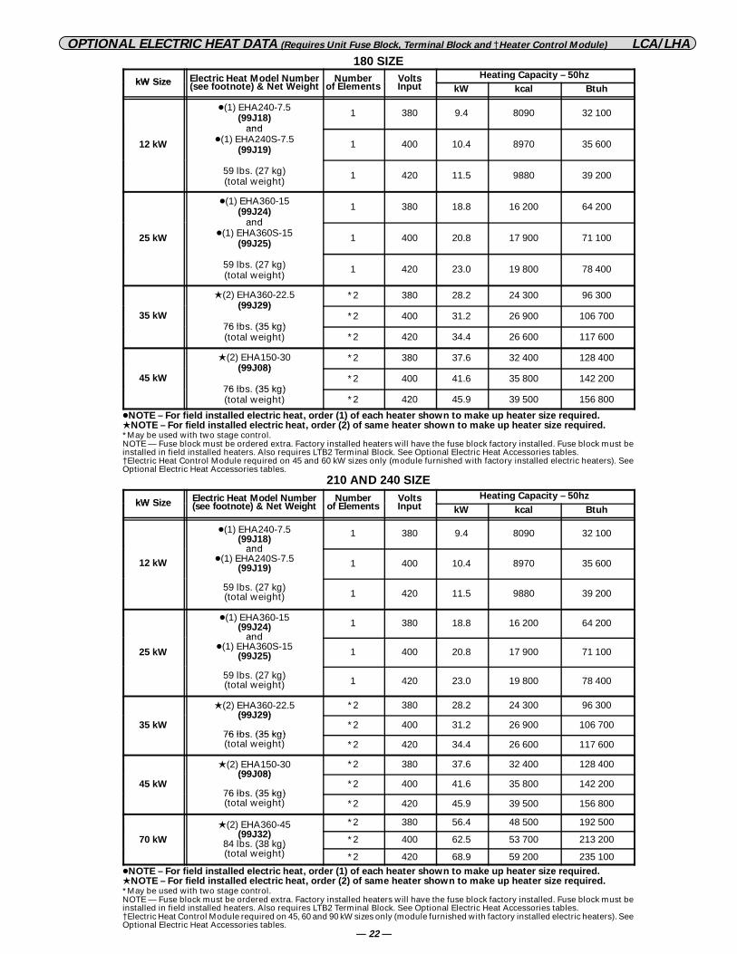
OPTIONAL ELECTRIC HEAT DATA (Requires Unit Fuse Block, Terminal Block and �Heater Control Module) LCA/LHA
180 SIZE
kW Size Electric Heat Model Number( )
Number Volts Heating Capacity – 50hzkW Size Electric Heat Model Number
(see footnote) & Net WeightNumber
of ElementsVoltsInput kW kcal Btuh
�(1) EHA240-7.5(99J18)
and
1 380 9.4 8090 32 100
12 kW
and�(1) EHA240S-7.5
(99J19)1 400 10.4 8970 35 600
59 lbs. (27 kg)(total weight)
1 420 11.5 9880 39 200
�(1) EHA360-15(99J24)
and
1 380 18.8 16 200 64 200
25 kW
and�(1) EHA360S-15
(99J25)1 400 20.8 17 900 71 100
59 lbs. (27 kg)(total weight)
1 420 23.0 19 800 78 400
�(2) EHA360-22.5(99J29)
*2 380 28.2 24 300 96 300
35 kW(99J29)
76 lbs (35 kg)*2 400 31.2 26 900 106 700
76 lbs. (35 kg)(total weight) *2 420 34.4 26 600 117 600
�(2) EHA150-30(99J08)
*2 380 37.6 32 400 128 400
45 kW(99J08)
76 lbs (35 kg)*2 400 41.6 35 800 142 200
76 lbs. (35 kg)(total weight) *2 420 45.9 39 500 156 800
�NOTE – For field installed electric heat, order (1) of each heater shown to make up heater size required.�NOTE – For field installed electric heat, order (2) of same heater shown to make up heater size required.*May be used with two stage control.NOTE — Fuse block must be ordered extra. Factory installed heaters will have the fuse block factory installed. Fuse block must beinstalled in field installed heaters. Also requires LTB2 Terminal Block. See Optional Electric Heat Accessories tables.�Electric Heat Control Module required on 45 and 60 kW sizes only (module furnished with factory installed electric heaters). SeeOptional Electric Heat Accessories tables.
210 AND 240 SIZE
kW SizeElectric Heat Model Number( f t t ) & N t W i ht
Numberf El t
VoltsI t
Heating Capacity – 50hzkW Size (see footnote) & Net Weight of Elements Input kW kcal Btuh
�(1) EHA240-7.5(99J18)
and
1 380 9.4 8090 32 100
12 kW
and�(1) EHA240S-7.5
(99J19)1 400 10.4 8970 35 600
59 lbs. (27 kg)(total weight) 1 420 11.5 9880 39 200
�(1) EHA360-15(99J24)
and1 380 18.8 16 200 64 200
25 kW
and�(1) EHA360S-15
(99J25) 1 400 20.8 17 900 71 100
59 lbs. (27 kg)(total weight) 1 420 23.0 19 800 78 400
�(2) EHA360-22.5(99J29)
*2 380 28.2 24 300 96 300
35 kW(99J29)
76 lbs (35 kg)*2 400 31.2 26 900 106 700
76 lbs. (35 kg)(total weight) *2 420 34.4 26 600 117 600
�(2) EHA150-30(99J08)
*2 380 37.6 32 400 128 400
45 kW(99J08)
76 lbs (35 kg)*2 400 41.6 35 800 142 200
76 lbs. (35 kg)(total weight) *2 420 45.9 39 500 156 800
�(2) EHA360-45(99J32)
*2 380 56.4 48 500 192 500
70 kW(99J32)
84 lbs. (38 kg) *2 400 62.5 53 700 213 20084 lbs. (38 kg)(total weight) *2 420 68.9 59 200 235 100
�NOTE – For field installed electric heat, order (1) of each heater shown to make up heater size required.�NOTE – For field installed electric heat, order (2) of same heater shown to make up heater size required.*May be used with two stage control.NOTE — Fuse block must be ordered extra. Factory installed heaters will have the fuse block factory installed. Fuse block must beinstalled in field installed heaters. Also requires LTB2 Terminal Block. See Optional Electric Heat Accessories tables.�Electric Heat Control Module required on 45, 60 and 90 kW sizes only (module furnished with factory installed electric heaters). SeeOptional Electric Heat Accessories tables.
— 22 —

LCA/LGACOOLING RATINGS
NOTE — For Temperatures and Capacities not shown in tables, see bulletin — Cooling Unit Rating Table Correction Factor Data in Miscellaneous Engineering Data section.
2.25 4800 36.8 125 500 6.98 .70 .84 .97 34.3 117 100 7.50 .70 .86 .99 31.7 108 300 8.10 .71 .87 1.00 29.0 98 900 8.77 .72 .90 1.002.85 6000 38.2 130 200 7.05 .75 .92 1.00 35.6 121 600 7.59 .76 .94 1.00 33.0 112 600 8.23 .77 .96 1.00 30.3 103 300 8.93 .79 .98 1.003.40 7200 39.4 134 300 7.10 .81 .98 1.00 36.8 125 700 7.67 .82 .99 1.00 34.2 116 700 8.35 .84 1.00 1.00 31.6 107 700 9.10 .86 1.00 1.002.25 4800 39.1 133 300 7.09 .56 .68 .80 36.5 124 600 7.65 .55 .68 .82 33.8 115 200 8.30 .55 .69 .84 30.9 105 400 9.01 .54 .70 .862.85 6000 40.3 137 500 7.14 .58 .73 .88 37.6 128 400 7.73 .58 .73 .90 34.8 118 700 8.40 .58 .75 .93 31.9 108 700 9.13 .58 .77 .953.40 7200 41.2 140 500 7.18 .61 .78 .95 38.5 131 200 7.78 .61 .80 .97 35.5 121 200 8.48 .62 .82 .99 32.5 111 000 9.22 .62 .84 1.002.25 4800 41.6 142 100 7.20 .43 .54 .65 38.9 132 900 7.82 .41 .53 .66 36.1 123 100 8.52 .40 .53 .66 33.1 112 900 9.29 .39 .53 .672.85 6000 42.8 146 100 7.24 .43 .57 .70 40.0 136 600 7.89 .43 .57 .71 37.0 126 400 8.62 .42 .57 .72 34.0 116 000 9.40 .40 .57 .743.40 7200 43.6 148 900 7.28 .45 .60 .76 40.8 139 100 7.94 .44 .60 .77 37.7 128 700 8.68 .43 .61 .79 34.6 118 000 9.48 .42 .62 .82
Enter-ingWetBulb
Temper-ature
TotalAir
Volume
m3/s cfm
TotalCoolingCapacity
Btuh
Com-pressorMotor
kW
SensibleTo Total
Ratio (S/T)
Dry Bulb Dry Bulb Dry Bulb Dry Bulb
SensibleTo Total
Ratio (S/T)
SensibleTo Total
Ratio (S/T)
SensibleTo Total
Ratio (S/T)Com-
pressorMotor
kW
Com-pressorMotor
kW
Com-pressorMotor
kW
TotalCoolingCapacity
TotalCoolingCapacity
TotalCoolingCapacity
Outdoor Temperature
17.2°C(63°F)
19.4°C(67°F)
21.7°C(71°F)
BtuhkW kW kWBtuh BtuhkW
18°C (65°F) 24°C (75°F) 29° C (85°F) 35°C (95°F)
LCA/LGA180S — TWO COMPRESSORS OPERATING
75°F 80°F 85°F24°C 27°C 29°C
75°F 80°F 85°F24°C 27°C 29°C
75°F 80°F85°F24°C 27°C29°C
75°F 80°F85°F24°C 27°C29°C
2.25 4800 46.9 160 000 12.25 .73 .88 1.00 43.4 148 100 13.26 .74 .91 1.00 39.9 136 000 14.31 .76 .94 1.00 36.3 124 000 15.37 .78 .97 1.002.85 6000 48.8 166 400 12.44 .79 .96 1.00 45.3 154 400 13.51 .81 .99 1.00 41.8 142 600 14.64 .83 1.00 1.00 38.4 131 100 15.80 .86 1.00 1.003.40 7200 50.6 172 600 12.64 .85 1.00 1.00 47.2 161 000 13.77 .88 1.00 1.00 43.7 149 000 14.95 .91 1.00 1.00 40.2 137 000 16.15 .94 1.00 1.002.25 4800 49.9 170 200 12.57 .56 .70 .85 46.2 157 600 13.63 .56 .72 .87 42.4 144 600 14.74 .57 .73 .90 38.6 131 800 15.85 .57 .75 .932.85 6000 51.4 175 400 12.72 .60 .77 .93 47.6 162 300 13.82 .60 .78 .96 43.6 148 900 14.96 .61 .81 .99 39.8 135 800 16.09 .62 .84 1.003.40 7200 52.5 179 100 12.84 .63 .83 .99 48.6 165 700 13.96 .64 .85 1.00 44.6 152 300 15.12 .66 .88 1.00 40.7 139 000 16.28 .67 .92 1.002.25 4800 53.3 181 700 12.91 .41 .55 .68 49.4 168 500 14.06 .41 .55 .69 45.4 155 000 15.25 .40 .55 .71 41.5 141 600 16.43 .39 .56 .732.85 6000 54.7 186 500 13.06 .43 .59 .74 50.7 173 000 14.23 .42 .59 .76 46.6 159 000 15.45 .41 .60 .78 42.5 145 100 16.64 .41 .61 .813.40 7200 55.7 189 900 13.16 .44 .63 .81 51.6 175 900 14.36 .44 .64 .83 47.4 161 600 15.58 .43 .65 .86 43.3 147 600 16.79 .43 .67 .90
Enter-ingWetBulb
Temper-ature
TotalAir
Volume
m3/s cfm
TotalCoolingCapacity
Btuh
Com-pressorMotor
kW
SensibleTo Total
Ratio (S/T)
Dry Bulb Dry Bulb Dry Bulb Dry Bulb
SensibleTo Total
Ratio (S/T)
SensibleTo Total
Ratio (S/T)
SensibleTo Total
Ratio (S/T)Com-
pressorMotor
kW
Com-pressorMotor
kW
Com-pressorMotor
kW
TotalCoolingCapacity
TotalCoolingCapacity
TotalCoolingCapacity
Outdoor Temperature
17.2°C(63°F)
19.4°C(67°F)
21.7°C(71°F)
BtuhkW kW kWBtuh BtuhkW
29°C (85°F) 35°C (95°F) 41° C (105°F) 46°C (115°F)
LCA/LGA180S — ALL COMPRESSORS OPERATING
75°F 80°F 85°F24°C 27°C 29°C
75°F 80°F 85°F24°C 27°C 29°C
75°F 80°F85°F24°C 27°C29°C
75°F 80°F85°F24°C 27°C29°C
2.65 5600 30.0 102 200 5.56 .71 .85 .99 27.7 94 500 6.03 .71 .87 1.00 25.4 86 800 6.58 .72 .89 1.00 23.2 79 000 7.18 .72 .92 1.003.30 7000 31.1 106 000 5.63 .76 .93 1.00 28.8 98 200 6.14 .77 .95 1.00 26.5 90 400 6.72 .78 .98 1.00 24.2 82 700 7.37 .80 1.00 1.003.95 8400 32.0 109 300 5.70 .82 .99 1.00 29.8 101 600 6.23 .83 1.00 1.00 27.6 94 100 6.86 .85 1.00 1.00 25.3 86 300 7.57 .88 1.00 1.002.65 5600 31.7 108 300 5.68 .56 .68 .82 29.4 100 400 6.20 .55 .69 .83 27.1 92 300 6.79 .55 .69 .85 24.6 84 100 7.45 .54 .70 .883.30 7000 32.7 111 500 5.74 .59 .73 .90 30.3 103 400 6.29 .59 .74 .92 27.8 95 000 6.90 .59 .76 .94 25.4 86 700 7.59 .58 .78 .973.95 8400 33.4 113 900 5.79 .62 .79 .97 30.9 105 600 6.35 .62 .81 .99 28.5 97 100 6.99 .62 .83 1.00 26.0 88 600 7.69 .63 .85 1.002.65 5600 33.8 115 400 5.82 .43 .54 .66 31.4 107 200 6.40 .41 .54 .66 28.9 98 700 7.06 .40 .53 .67 26.5 90 300 7.78 .38 .53 .683.30 7000 34.7 118 400 5.89 .44 .57 .71 32.2 110 000 6.49 .43 .57 .72 29.7 101 300 7.17 .41 .57 .73 27.1 92 600 7.92 .40 .57 .753.95 8400 35.3 120 600 5.94 .45 .61 .77 32.8 111 900 6.55 .44 .61 .78 30.2 103 100 7.25 .43 .61 .80 27.6 94 200 8.02 .42 .62 .83
Enter-ingWetBulb
Temper-ature
TotalAir
Volume
m3/s cfm
TotalCoolingCapacity
Btuh
Com-pressorMotor
kW
SensibleTo Total
Ratio (S/T)
Dry Bulb Dry Bulb Dry Bulb Dry Bulb
SensibleTo Total
Ratio (S/T)
SensibleTo Total
Ratio (S/T)
SensibleTo Total
Ratio (S/T)Com-
pressorMotor
kW
Com-pressorMotor
kW
Com-pressorMotor
kW
TotalCoolingCapacity
TotalCoolingCapacity
TotalCoolingCapacity
Outdoor Temperature
17.2°C(63°F)
19.4°C(67°F)
21.7°C(71°F)
BtuhkW kW kWBtuh BtuhkW
18°C (65°F) 24°C (75°F) 29° C (85°F) 35°C (95°F)
LCA/LGA210S — TWO COMPRESSORS OPERATING
75°F 80°F 85°F24°C 27°C 29°C
75°F 80°F 85°F24°C 27°C 29°C
75°F 80°F85°F24°C 27°C29°C
75°F 80°F85°F24°C 27°C29°C
2.65 5600 53.5 182 500 13.54 .73 .89 1.00 49.8 169 900 14.79 .74 .92 1.00 46.1 157 300 16.14 .75 .95 1.00 42.4 144 600 17.56 .77 .98 1.003.30 7000 55.7 189 900 13.83 .79 .98 1.00 52.0 177 300 15.18 .81 1.00 1.00 48.4 165 100 16.68 .83 1.00 1.00 44.8 152 800 18.29 .86 1.00 1.003.95 8400 57.9 197 400 14.13 .86 1.00 1.00 54.2 184 800 15.59 .88 1.00 1.00 50.4 172 100 17.19 .91 1.00 1.00 46.7 159 200 18.89 .95 1.00 1.002.65 5600 56.8 193 700 14.00 .56 .70 .85 52.9 180 400 15.35 .56 .71 .88 48.9 166 800 16.80 .56 .73 .91 44.9 153 100 18.32 .57 .75 .943.30 7000 58.5 199 500 14.23 .59 .76 .94 54.4 185 600 15.64 .60 .78 .97 50.3 171 700 17.15 .61 .81 .99 46.2 157 600 18.74 .62 .84 1.003.95 8400 59.7 203 600 14.41 .63 .83 1.00 55.6 189 600 15.87 .64 .86 1.00 51.4 175 500 17.43 .65 .89 1.00 47.3 161 300 19.07 .67 .92 1.002.65 5600 60.7 207 000 14.56 .41 .54 .68 56.5 192 900 16.06 .40 .55 .69 52.4 178 800 17.67 .39 .55 .71 48.2 164 300 19.36 .39 .56 .72.3.30 7000 62.2 212 300 14.79 .42 .58 .74 58.0 197 900 16.34 .42 .59 .76 53.7 183 100 18.01 .41 .60 .78 49.3 168 300 19.74 .41 .61 .813.95 8400 63.3 216 000 14.96 .44 .62 .81 58.9 201 100 16.55 .43 .63 .83 54.5 186 100 18.24 .43 .65 .86 50.1 171 100 20.01 .43 .66 .90
Enter-ingWetBulb
Temper-ature
TotalAir
Volume
m3/s cfm
TotalCoolingCapacity
Btuh
Com-pressorMotor
kW
SensibleTo Total
Ratio (S/T)
Dry Bulb Dry Bulb Dry Bulb Dry Bulb
SensibleTo Total
Ratio (S/T)
SensibleTo Total
Ratio (S/T)
SensibleTo Total
Ratio (S/T)Com-
pressorMotor
kW
Com-pressorMotor
kW
Com-pressorMotor
kW
TotalCoolingCapacity
TotalCoolingCapacity
TotalCoolingCapacity
Outdoor Temperature
17.2°C(63°F)
19.4°C(67°F)
21.7°C(71°F)
BtuhkW kW kWBtuh BtuhkW
29°C (85°F) 35°C (95°F) 41° C (105°F) 46°C (115°F)
LCA/LGA210S — ALL COMPRESSORS OPERATING
75°F 80°F 85°F24°C 27°C 29°C
75°F 80°F 85°F24°C 27°C 29°C
75°F 80°F85°F24°C 27°C29°C
75°F 80°F85°F24°C 27°C29°C
— 23 —
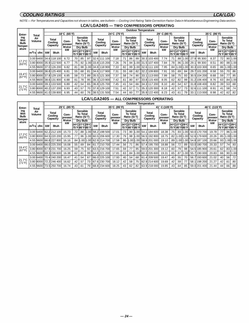
LCA/LGACOOLING RATINGS
NOTE — For Temperatures and Capacities not shown in tables, see bulletin — Cooling Unit Rating Table Correction Factor Data in Miscellaneous Engineering Data section.
3.00 6400 34.6 118 100 6.72 .70 .85 .97 32.6 111 100 7.18 .71 .86 .99 30.3 103 400 7.74 .71 .88 1.00 27.9 95 300 8.37 .72 .90 1.003.80 8000 35.9 122 500 6.77 .75 .92 1.00 33.8 115 200 7.26 .76 .94 1.00 31.5 107 400 7.84 .78 .96 1.00 29.1 99 300 8.51 .80 .98 1.004.55 9600 37.0 126 200 6.82 .81 .98 1.00 34.8 118 900 7.33 .82 .99 1.00 32.6 111 100 7.95 .84 1.00 1.00 30.3 103 300 8.65 .86 1.00 1.003.00 6400 36.8 125 400 6.81 .55 .68 .81 34.6 117 900 7.31 .55 .68 .82 32.2 109 800 7.91 .55 .69 .84 29.7 101 200 8.58 .55 .70 .863.80 8000 37.8 129 100 6.85 .58 .73 .89 35.5 121 300 7.37 .58 .74 .90 33.1 113 000 7.99 .58 .75 .93 30.5 104 200 8.68 .59 .77 .954.55 9600 38.6 131 800 6.88 .61 .78 .95 36.3 123 900 7.42 .61 .80 .97 33.8 115 400 8.05 .62 .82 .99 31.2 106 400 8.76 .63 .84 1.003.00 6400 39.1 133 500 6.89 .42 .54 .65 36.8 125 700 7.45 .41 .54 .66 34.3 117 200 8.10 .40 .54 .67 31.8 108 400 8.82 .39 .53 .683.80 8000 40.2 137 200 6.93 .43 .57 .70 37.8 129 100 7.51 .42 .57 .71 35.3 120 300 8.18 .42 .57 .73 32.6 111 100 8.91 .41 .58 .744.55 9600 41.0 139 800 6.95 .44 .60 .76 38.5 131 500 7.54 .44 .60 .77 35.9 122 400 8.23 .43 .61 .79 33.1 113 000 8.98 .42 .62 .82
Enter-ingWetBulb
Temper-ature
TotalAir
Volume
m3/s cfm
TotalCoolingCapacity
Btuh
Com-pressorMotor
kW
SensibleTo Total
Ratio (S/T)
Dry Bulb Dry Bulb Dry Bulb Dry Bulb
SensibleTo Total
Ratio (S/T)
SensibleTo Total
Ratio (S/T)
SensibleTo Total
Ratio (S/T)Com-
pressorMotor
kW
Com-pressorMotor
kW
Com-pressorMotor
kW
TotalCoolingCapacity
TotalCoolingCapacity
TotalCoolingCapacity
Outdoor Temperature
17.2°C(63°F)
19.4°C(67°F)
21.7°C(71°F)
BtuhkW kW kWBtuh BtuhkW
18°C (65°F) 24°C (75°F) 29° C (85°F) 35°C (95°F)
LCA/LGA240S — TWO COMPRESSORS OPERATING
75°F 80°F 85°F24°C 27°C 29°C
75°F 80°F 85°F24°C 27°C 29°C
75°F 80°F85°F24°C 27°C29°C
75°F 80°F85°F24°C 27°C29°C
3.00 6400 62.2 212 100 15.73 .72 .88 1.00 58.2 198 500 17.01 .73 .90 1.00 54.1 184 600 18.38 .75 .93 1.00 50.0 170 700 19.78 .77 .96 1.003.80 8000 64.5 220 200 15.95 .77 .96 1.00 60.5 206 600 17.30 .79 .98 1.00 56.5 192 800 18.75 .82 1.00 1.00 52.6 179 600 20.26 .85 1.00 1.004.55 9600 66.8 227 800 16.16 .84 1.00 1.00 62.9 214 700 17.58 .86 1.00 1.00 58.9 201 000 19.10 .89 1.00 1.00 54.8 187 100 20.66 .93 1.00 1.003.00 6400 66.0 225 200 16.08 .55 .69 .84 61.7 210 700 17.44 .56 .71 .86 57.4 195 700 18.88 .56 .72 .89 53.0 180 700 20.33 .57 .74 .933.80 8000 67.9 231 700 16.25 .59 .75 .92 63.5 216 700 17.65 .59 .77 .95 59.0 201 300 19.12 .60 .79 .98 54.5 185 900 20.61 .62 .83 1.004.55 9600 69.3 236 600 16.38 .62 .81 .99 64.8 221 200 17.81 .63 .84 1.00 60.3 205 600 19.31 .65 .87 1.00 55.7 190 000 20.83 .66 .90 1.003.00 6400 70.4 240 200 16.47 .41 .54 .67 66.0 225 100 17.93 .40 .54 .68 61.4 209 500 19.47 .40 .55 .70 56.7 193 600 21.02 .40 .56 .723.80 8000 72.2 246 400 16.62 .42 .57 .73 67.6 230 700 18.12 .42 .58 .75 62.9 214 600 19.69 .42 .59 .77 58.1 198 200 21.27 .42 .61 .804.55 9600 73.5 250 700 16.74 .43 .61 .79 68.8 234 600 18.25 .43 .62 .82 63.9 218 000 19.85 .43 .64 .85 59.0 201 400 21.44 .44 .66 .88
Enter-ingWetBulb
Temper-ature
TotalAir
Volume
m3/s cfm
TotalCoolingCapacity
Btuh
Com-pressorMotor
kW
SensibleTo Total
Ratio (S/T)
Dry Bulb Dry Bulb Dry Bulb Dry Bulb
SensibleTo Total
Ratio (S/T)
SensibleTo Total
Ratio (S/T)
SensibleTo Total
Ratio (S/T)Com-
pressorMotor
kW
Com-pressorMotor
kW
Com-pressorMotor
kW
TotalCoolingCapacity
TotalCoolingCapacity
TotalCoolingCapacity
Outdoor Temperature
17.2°C(63°F)
19.4°C(67°F)
21.7°C(71°F)
BtuhkW kW kWBtuh BtuhkW
29°C (85°F) 35°C (95°F) 41° C (105°F) 46°C (115°F)
LCA/LGA240S — ALL COMPRESSORS OPERATING
75°F 80°F 85°F24°C 27°C 29°C
75°F 80°F 85°F24°C 27°C 29°C
75°F 80°F85°F24°C 27°C29°C
75°F 80°F85°F24°C 27°C29°C
— 24 —

LHACOOLING AND HEATING RATINGS
NOTE — For Temperatures and Capacities not shown in tables, see bulletin — Cooling Unit Rating Table Correction Factor Data in Miscellaneous Engineering Data section.
2.25 4800 26.8 91 400 4.63 .71 .84 .97 24.7 84 300 5.13 .71 .85 .98 22.6 77 100 5.65 .71 .87 1.00 20.5 69 800 6.18 .71 .88 1.002.85 6000 27.8 95 000 4.65 .76 .91 1.00 25.7 87 800 5.16 .76 .93 1.00 23.6 80 400 5.70 .77 .95 1.00 21.4 72 900 6.26 .78 .97 1.003.40 7200 28.7 98 000 4.66 .81 .97 1.00 26.6 90 800 5.19 .82 .99 1.00 24.4 83 400 5.75 .83 1.00 1.00 22.3 76 100 6.34 .85 1.00 1.002.25 4800 28.5 97 400 4.66 .57 .68 .81 26.4 90 100 5.19 .56 .68 .82 24.2 82 500 5.73 .55 .68 .83 21.9 74 800 6.31 .53 .68 .842.85 6000 29.5 100 600 4.67 .59 .73 .88 27.3 93 000 5.22 .59 .74 .89 25.0 85 200 5.78 .58 .74 .91 22.7 77 300 6.37 .57 .75 .943.40 7200 30.2 102 900 4.68 .62 .78 .94 27.9 95 200 5.23 .62 .79 .96 25.6 87 300 5.81 .61 .81 .98 23.2 79 200 6.41 .61 .82 1.002.25 4800 30.5 104 000 4.69 .44 .55 .66 28.3 96 400 5.24 .42 .54 .66 26.0 88 600 5.83 .40 .53 .66 23.6 80 600 6.44 .38 .52 .662.85 6000 31.4 107 100 4.70 .45 .58 .71 29.1 99 400 5.27 .43 .57 .71 26.8 91 300 5.87 .41 .57 .72 24.3 83 000 6.49 .39 .56 .733.40 7200 32.0 109 300 4.71 .46 .61 .76 29.7 101 400 5.29 .44 .60 .77 27.3 93 100 5.90 .43 .60 .78 24.8 84 700 6.53 .41 .60 .80
Enter-ingWetBulb
Temper-ature
TotalAir
Volume
m3/s cfm
TotalCoolingCapacity
Btuh
Com-pressorMotor
kW
SensibleTo Total
Ratio (S/T)
Dry Bulb Dry Bulb Dry Bulb Dry Bulb
SensibleTo Total
Ratio (S/T)
SensibleTo Total
Ratio (S/T)
SensibleTo Total
Ratio (S/T)Com-pressorMotor
kW
Com-pressorMotor
kW
Com-pressorMotor
kW
TotalCoolingCapacity
TotalCoolingCapacity
TotalCoolingCapacity
Outdoor Temperature
17.2°C(63°F)
19.4°C(67°F)
21.7°C(71°F)
BtuhkW kW kWBtuh BtuhkW
18°C (65°F) 24°C (75°F) 29° C (85°F) 35°C (95°F)
LHA180H — COOLING CAPACITY — ONE COMPRESSOR OPERATING
75°F 80°F 85°F24°C 27°C 29°C
75°F 80°F 85°F24°C 27°C 29°C
75°F 80°F85°F24°C 27°C29°C
75°F 80°F85°F24°C 27°C29°C
2.25 4800 46.2 157 500 11.14 .73 .88 1.00 42.9 146 500 12.20 .73 .89 1.00 39.6 135 100 13.33 .75 .92 1.00 36.2 123 600 14.50 .76 .94 1.002.85 6000 48.1 164 100 11.25 .78 .95 1.00 44.8 152 900 12.36 .80 .97 1.00 41.5 141 600 13.52 .82 .99 1.00 38.2 130 200 14.80 .84 1.00 1.003.40 7200 49.9 170 200 11.35 .84 1.00 1.00 46.7 159 300 12.51 .86 1.00 1.00 43.4 148 200 13.74 .88 1.00 1.00 40.0 136 600 15.06 .91 1.00 1.002.25 4800 49.3 168 300 11.32 .56 .70 .84 45.9 156 600 12.44 .56 .71 .86 42.4 144 600 13.63 .56 .72 .88 38.7 132 200 14.88 .56 .73 .912.85 6000 51.0 173 900 11.40 .60 .76 .92 47.4 161 800 12.56 .60 .77 .94 43.8 149 300 13.78 .60 .79 .96 40.0 136 500 15.07 .61 .81 .993.40 7200 52.1 177 900 11.47 .63 .82 .98 48.5 165 600 12.65 .64 .84 1.00 44.8 152 800 13.89 .64 .86 1.00 41.0 139 800 15.20 .65 .89 1.002.25 4800 52.9 180 500 11.50 .41 .54 .67 49.3 168 300 12.71 .40 .54 .68 45.6 155 700 13.98 .39 .54 .69 41.8 142 500 15.32 .38 .54 .712.85 6000 54.5 186 000 11.58 .43 .58 .73 50.8 173 300 12.82 .42 .58 .75 46.9 160 100 14.12 .41 .59 .76 42.9 146 400 15.49 .40 .60 .793.40 7200 55.6 189 700 11.64 .44 .62 .79 51.8 176 600 12.89 .43 .63 .81 47.8 163 100 14.21 .43 .63 .84 43.7 149 000 15.60 .42 .65 .87
Enter-ingWetBulb
Temper-ature
TotalAir
Volume
m3/s cfm
TotalCoolingCapacity
Btuh
Com-pressorMotor
kW
SensibleTo Total
Ratio (S/T)
Dry Bulb Dry Bulb Dry Bulb Dry Bulb
SensibleTo Total
Ratio (S/T)
SensibleTo Total
Ratio (S/T)
SensibleTo Total
Ratio (S/T)Com-pressorMotor
kW
Com-pressorMotor
kW
Com-pressorMotor
kW
TotalCoolingCapacity
TotalCoolingCapacity
TotalCoolingCapacity
Outdoor Temperature
17.2°C(63°F)
19.4°C(67°F)
21.7°C(71°F)
BtuhkW kW kWBtuh BtuhkW
29°C (85°F) 35°C (95°F) 41° C (105°F) 46°C (115°F)
LHA180H — COOLING CAPACITY — ALL COMPRESSORS OPERATING
75°F 80°F 85°F24°C 27°C 29°C
75°F 80°F 85°F24°C 27°C 29°C
75°F 80°F85°F24°C 27°C29°C
75°F 80°F85°F24°C 27°C29°C
2.25 4800 60.1 205,000 13.4 45.7 156,000 11.4 31.3 106,900 9.4 20.9 71,200 7.5 10.4 35,500 5.62.85 6000 60.5 206,600 13.5 46.2 157,600 11.5 31.8 108,500 9.5 21.3 72,800 7.6 10.9 37,100 5.73.40 7200 61.0 208,300 13.6 46.7 159,400 11.6 32.3 110,200 9.6 21.8 74,500 7.7 11.4 38,900 5.8
*At 70% relative humidity.NOTE — Heating performance includes the effect of defrost cycles in the temperature range where they occur.
Indoor CoilAir Volume
70°F db(21°C db)
TotalHeatingCapacity
Com-pressorMotor
kWm3/s cfm kW Btuh kW Btuh kW Btuh kW Btuh kW Btuh
TotalHeatingCapacity
Com-pressorMotor
kW
TotalHeatingCapacity
Com-pressorMotor
kW
TotalHeatingCapacity
Com-pressorMotor
kW
TotalHeatingCapacity
Com-pressorMotor
kW
*Outdoor Temperature
65°F (18°C) 45°F (7°C) 25°F (minus4°C) 5°F (minus15°C) minus15°F (minus28°C)
LHA180H — HEATING PERFORMANCE — ALL COMPRESSORS OPERATING
— 25 —

LHACOOLING AND HEATING RATINGS
NOTE — For Temperatures and Capacities not shown in tables, see bulletin — Cooling Unit Rating Table Correction Factor Data in Miscellaneous Engineering Data section.
2.85 6000 33.4 114 100 5.47 .70 .85 .99 31.0 105 900 6.06 .70 .87 1.00 28.6 97 500 6.67 .71 .89 1.00 26.1 88 900 7.31 .72 .91 1.003.55 7500 34.8 118 700 5.50 .76 .94 1.00 32.4 110 400 6.12 .77 .96 1.00 29.9 101 900 6.76 .78 .98 1.00 27.3 93 300 7.43 .80 1.00 1.004.25 9000 36.0 122 800 5.53 .82 1.00 1.00 33.6 114 700 6.17 .84 1.00 1.00 31.2 106 400 6.84 .86 1.00 1.00 28.7 97 800 7.54 .88 1.00 1.002.85 6000 35.5 121 300 5.52 .55 .68 .81 33.0 112 700 6.14 .55 .68 .83 30.4 103 900 6.79 .54 .68 .85 27.8 94 800 7.47 .54 .69 .873.55 7500 36.7 125 100 5.54 .59 .73 .90 34.1 116 200 6.19 .58 .74 .92 31.4 107 200 6.85 .58 .75 .95 28.7 97 900 7.55 .58 .77 .984.25 9000 37.5 127 900 5.57 .62 .80 .98 34.8 118 900 6.22 .62 .81 .99 32.1 109 700 6.90 .62 .83 1.00 29.4 100 200 7.61 .62 .86 1.002.85 6000 37.9 129 300 5.58 .42 .54 .65 35.3 120 500 6.23 .41 .53 .66 32.6 111 200 6.92 .39 .53 .66 29.8 101 800 7.65 .38 .52 .673.55 7500 38.9 132 900 5.60 .43 .57 .71 36.3 123 900 6.27 .42 .57 .72 33.5 114 300 6.98 .41 .57 .73 30.6 104 500 7.72 .39 .57 .744.25 9000 39.7 135 400 5.62 .45 .61 .77 37.0 126 100 6.30 .44 .61 .78 34.1 116 400 7.02 .43 .61 .80 31.2 106 400 7.77 .41 .62 .83
Enter-ingWetBulb
Temper-ature
TotalAir
Volume
m3/s cfm
TotalCoolingCapacity
Btuh
Com-pressorMotor
kW
SensibleTo Total
Ratio (S/T)
Dry Bulb Dry Bulb Dry Bulb Dry Bulb
SensibleTo Total
Ratio (S/T)
SensibleTo Total
Ratio (S/T)
SensibleTo Total
Ratio (S/T)Com-pressorMotor
kW
Com-pressorMotor
kW
Com-pressorMotor
kW
TotalCoolingCapacity
TotalCoolingCapacity
TotalCoolingCapacity
Outdoor Temperature
17.2°C(63°F)
19.4°C(67°F)
21.7°C(71°F)
BtuhkW kW kWBtuh BtuhkW
18°C (65°F) 24°C (75°F) 29° C (85°F) 35°C (95°F)
LHA240H — COOLING CAPACITY — ONE COMPRESSOR OPERATING
75°F 80°F 85°F24°C 27°C 29°C
75°F 80°F 85°F24°C 27°C 29°C
75°F 80°F85°F24°C 27°C29°C
75°F 80°F85°F24°C 27°C29°C
2.85 6000 58.5 199 700 13.30 .74 .90 1.00 54.6 186 300 14.57 .75 .93 1.00 50.6 172 700 15.91 .77 .95 1.00 46.6 158 900 17.33 .79 .98 1.003.55 7500 61.1 208 500 13.47 .80 .98 1.00 57.2 195 200 14.80 .82 1.00 1.00 53.4 182 100 16.24 .85 1.00 1.00 49.4 168 500 17.78 .88 1.00 1.004.25 9000 63.8 217 700 13.63 .87 1.00 1.00 59.9 204 400 15.03 .90 1.00 1.00 55.8 190 500 16.52 .93 1.00 1.00 51.6 175 900 18.13 .96 1.00 1.002.85 6000 62.3 212 600 13.54 .57 .72 .86 58.1 198 400 14.88 .57 .73 .89 53.8 183 700 16.29 .57 .74 .91 49.4 168 500 17.77 .58 .76 .953.55 7500 64.3 219 500 13.66 .61 .78 .95 60.0 204 600 15.04 .61 .80 .98 55.5 189 400 16.48 .62 .82 1.00 50.9 173 700 18.02 .63 .85 1.004.25 9000 65.8 224 400 13.75 .65 .85 1.00 61.3 209 300 15.16 .66 .87 1.00 56.8 193 800 16.64 .67 .90 1.00 52.1 177 900 18.21 .69 .94 1.002.85 6000 66.7 227 500 13.81 .42 .55 .69 62.3 212 500 15.24 .41 .56 .70 57.7 197 000 16.75 .40 .56 .72 53.0 180 700 18.34 .39 .57 .743.55 7500 68.5 233 700 13.92 .43 .60 .76 63.9 218 200 15.39 .43 .60 .78 59.1 201 800 16.93 .42 .61 .80 54.2 185 100 18.55 .42 .62 .834.25 9000 69.8 238 100 14.00 .45 .64 .83 65.0 221 900 15.49 .45 .65 .85 60.2 205 300 17.05 .44 .66 .88 55.2 188 200 18.70 .44 .68 .92
Enter-ingWetBulb
Temper-ature
TotalAir
Volume
m3/s cfm
TotalCoolingCapacity
Btuh
Com-pressorMotor
kW
SensibleTo Total
Ratio (S/T)
Dry Bulb Dry Bulb Dry Bulb Dry Bulb
SensibleTo Total
Ratio (S/T)
SensibleTo Total
Ratio (S/T)
SensibleTo Total
Ratio (S/T)Com-pressorMotor
kW
Com-pressorMotor
kW
Com-pressorMotor
kW
TotalCoolingCapacity
TotalCoolingCapacity
TotalCoolingCapacity
Outdoor Temperature
17.2°C(63°F)
19.4°C(67°F)
21.7°C(71°F)
BtuhkW kW kWBtuh BtuhkW
29°C (85°F) 35°C (95°F) 41° C (105°F) 46°C (115°F)
LHA240H — COOLING CAPACITY — ALL COMPRESSORS OPERATING
75°F 80°F 85°F24°C 27°C 29°C
75°F 80°F 85°F24°C 27°C 29°C
75°F 80°F85°F24°C 27°C29°C
75°F 80°F85°F24°C 27°C29°C
2.85 6000 70.0 238,800 15.5 53.3 181,900 13.3 36.4 124,300 10.9 24.1 82,300 8.7 11.9 40,700 6.53.55 7500 70.8 241,500 15.7 54.1 184,500 13.4 37.2 126,900 11.0 24.9 84,900 8.9 12.7 43,300 6.74.25 9000 71.4 243,600 15.8 54.7 186,700 13.5 37.8 129,100 11.1 25.5 87,100 9.0 13.3 45,500 6.8
*At 70% relative humidity.NOTE — Heating performance includes the effect of defrost cycles in the temperature range where they occur.
Indoor CoilAir Volume
70°F db(21°C db)
TotalHeatingCapacity
Com-pressorMotor
kWm3/s cfm kW Btuh kW Btuh kW Btuh kW Btuh kW Btuh
TotalHeatingCapacity
Com-pressorMotor
kW
TotalHeatingCapacity
Com-pressorMotor
kW
TotalHeatingCapacity
Com-pressorMotor
kW
TotalHeatingCapacity
Com-pressorMotor
kW
*Outdoor Temperature
65°F (18°C) 45°F (7°C) 25°F (minus4°C) 5°F (minus15°C) minus15°F (minus28°C)
LHA240H — HEATING PERFORMANCE — ALL COMPRESSORS OPERATING
— 26 —
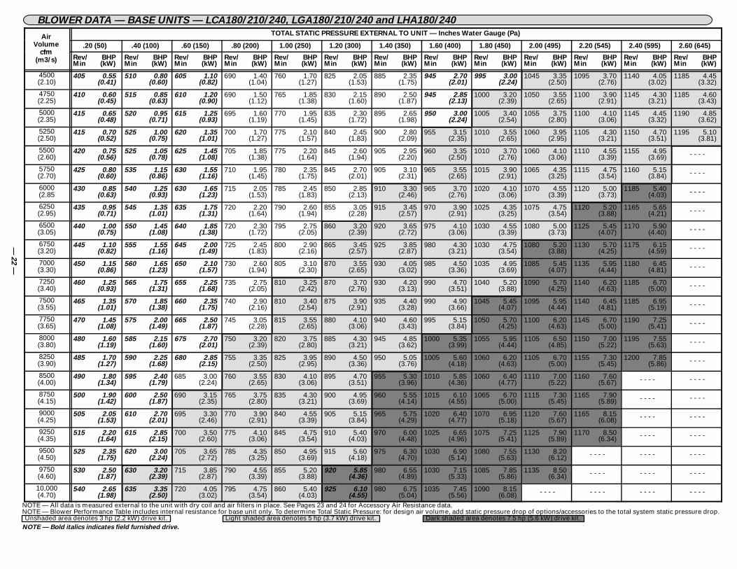
BLOWER DATA — BASE UNITS — LCA180/210/240, LGA180/210/240 and LHA180/240
AirTOTAL STATIC PRESSURE EXTERNAL TO UNIT — Inches Water Gauge (Pa)
Volumecfm
.20 (50) .40 (100) .60 (150) .80 (200) 1.00 (250) 1.20 (300) 1.40 (350) 1.60 (400) 1.80 (450) 2.00 (495) 2.20 (545) 2.40 (595) 2.60 (645)cfm
(m3/s) Rev/ BHPMin (kW)
Rev/ BHPMin (kW)
Rev/ BHPMin (kW)
Rev/ BHPMin (kW)
Rev/ BHPMin (kW)
Rev/ BHPMin (kW)
Rev/ BHPMin (kW)
Rev/ BHPMin (kW)
Rev/ BHPMin (kW)
Rev/ BHPMin (kW)
Rev/ BHPMin (kW)
Rev/ BHPMin (kW)
Rev/ BHPMin (kW)
4500(2.10)
405 0.55(0.41)
510 0.80(0.60)
605 1.10(0.82)
690 1.40(1.04)
760 1.70(1.27)
825 2.05(1.53)
885 2.35(1.75)
945 2.70(2.01)
995 3.00(2.24)
1045 3.35(2.50)
1095 3.70(2.76)
1140 4.05(3.02)
1185 4.45(3.32)
4750(2.25)
410 0.60(0.45)
515 0.85(0.63)
610 1.20(0.90)
690 1.50(1.12)
765 1.85(1.38)
830 2.15(1.60)
890 2.50(1.87)
945 2.85(2.13)
1000 3.20(2.39)
1050 3.55(2.65)
1100 3.90(2.91)
1145 4.30(3.21)
1185 4.60(3.43)
5000(2.35)
415 0.65(0.48)
520 0.95(0.71)
615 1.25(0.93)
695 1.60(1.19)
770 1.95(1.45)
835 2.30(1.72)
895 2.65(1.98)
950 3.00(2.24)
1005 3.40(2.54)
1055 3.75(2.80)
1100 4.10(3.06)
1145 4.45(3.32)
1190 4.85(3.62)
5250(2.50)
415 0.70(0.52)
525 1.00(0.75)
620 1.35(1.01)
700 1.70(1.27)
775 2.10(1.57)
840 2.45(1.83)
900 2.80(2.09)
955 3.15(2.35)
1010 3.55(2.65)
1060 3.95(2.95)
1105 4.30(3.21)
1150 4.70(3.51)
1195 5.10(3.81)
5500(2.60)
420 0.75(0.56)
525 1.05(0.78)
625 1.45(1.08)
705 1.85(1.38)
775 2.20(1.64)
845 2.60(1.94)
905 2.95(2.20)
960 3.35(2.50)
1010 3.70(2.76)
1060 4.10(3.06)
1110 4.55(3.39)
1155 4.95(3.69) - - - -
5750(2.70)
425 0.80(0.60)
535 1.15(0.86)
630 1.55(1.16)
710 1.95(1.45)
780 2.35(1.75)
845 2.70(2.01)
905 3.10(2.31)
965 3.55(2.65)
1015 3.90(2.91)
1065 4.35(3.25)
1115 4.75(3.54)
1160 5.15(3.84) - - - -
6000(2.85
430 0.85(0.63)
540 1.25(0.93)
630 1.65(1.23)
715 2.05(1.53)
785 2.45(1.83)
850 2.85(2.13)
910 3.30(2.46)
965 3.70(2.76)
1020 4.10(3.06)
1070 4.55(3.39)
1120 5.00(3.73)
1185 5.40(4.03) - - - -
6250(2.95)
435 0.95(0.71)
545 1.35(1.01)
635 1.75(1.31)
720 2.20(1.64)
790 2.60(1.94)
855 3.05(2.28)
915 3.45(2.57)
970 3.90(2.91)
1025 4.35(3.25)
1075 4.75(3.54)
1120 5.20(3.88)
1165 5.65(4.21) - - - -
6500(3.05)
440 1.00(0.75)
550 1.45(1.08)
640 1.85(1.38)
720 2.30(1.72)
795 2.75(2.05)
860 3.20(2.39)
920 3.65(2.72)
975 4.10(3.06)
1030 4.55(3.39)
1080 5.00(3.73)
1125 5.45(4.07)
1170 5.90(4.40) - - - -
6750(3.20)
445 1.10(0.82)
555 1.55(1.16)
645 2.00(1.49)
725 2.45(1.83)
800 2.90(2.16)
865 3.45(2.57)
925 3.85(2.87)
980 4.30(3.21)
1030 4.75(3.54)
1080 5.20(3.88)
1130 5.70(4.25)
1175 6.15(4.59) - - - -
7000(3.30)
450 1.15(0.86)
560 1.65(1.23)
650 2.10(1.57)
730 2.60(1.94)
805 3.10(2.30)
870 3.55(2.65)
930 4.05(3.02)
985 4.50(3.36)
1035 4.95(3.69)
1085 5.45(4.07)
1135 5.95(4.44)
1180 6.45(4.81) - - - -
7250(3.40)
460 1.25(0.93)
565 1.75(1.31)
655 2.25(1.68)
735 2.75(2.05)
810 3.25(2.42)
870 3.70(2.76)
930 4.20(3.13)
990 4.70(3.51)
1040 5.20(3.88)
1090 5.70(4.25)
1140 6.20(4.63)
1185 6.70(5.00) - - - -
7500(3.55)
465 1.35(1.01)
570 1.85(1.38)
660 2.35(1.75)
740 2.90(2.16)
810 3.40(2.54)
875 3.90(2.91)
935 4.40(3.28)
990 4.90(3.66)
1045 5.45(4.07)
1095 5.95(4.44)
1140 6.45(4.81)
1185 6.95(5.19) - - - -
7750(3.65)
470 1.45(1.08)
575 2.00(1.49)
665 2.50(1.87)
745 3.05(2.28)
815 3.55(2.65)
880 4.10(3.06)
940 4.60(3.43)
995 5.15(3.84)
1050 5.70(4.25)
1100 6.20(4.63)
1145 6.70(5.00)
1190 7.25(5.41) - - - -
8000(3.80)
480 1.60(1.19)
585 2.15(1.60)
675 2.70(2.01)
750 3.20(2.39)
820 3.75(2.80)
885 4.30(3.21)
945 4.85(3.62)
1000 5.35(3.99)
1055 5.95(4.44)
1105 6.50(4.85)
1150 7.00(5.22)
1195 7.55(5.63) - - - -
8250(3.90)
485 1.70(1.27)
590 2.25(1.68)
680 2.85(2.15)
755 3.35(2.50)
825 3.95(2.95)
890 4.50(3.36)
950 5.05(3.76)
1005 5.60(4.18)
1060 6.20(4.63)
1105 6.70(5.00)
1155 7.30(5.45)
1200 7.85(5.86) - - - -
8500(4.00)
490 1.80(1.34)
595 2.40(1.79)
685 3.00(2.24)
760 3.55(2.65)
830 4.10(3.06)
895 4.70(3.51)
955 5.30(3.96)
1010 5.85(4.36)
1060 6.40(4.77)
1110 7.00(5.22)
1160 7.60(5.67) - - - - - - - -
8750(4.15)
500 1.90(1.42)
600 2.50(1.87)
690 3.15(2.35)
765 3.75(2.80)
835 4.30(3.21)
900 4.95(3.69)
960 5.55(4.14)
1015 6.10(4.55)
1065 6.70(5.00)
1115 7.30(5.45)
1165 7.90(5.89) - - - - - - - -
9000(4.25)
505 2.05(1.53)
610 2.70(2.01)
695 3.30(2.46)
770 3.90(2.91)
840 4.55(3.39)
905 5.15(3.84)
965 5.75(4.29)
1020 6.40(4.77)
1070 6.95(5.18)
1120 7.60(5.67)
1165 8.15(6.08) - - - - - - - -
9250(4.35)
515 2.20(1.64)
615 2.85(2.15)
700 3.50(2.60)
775 4.10(3.06)
845 4.75(3.54)
910 5.40(4.03)
970 6.00(4.48)
1025 6.65(4.96)
1075 7.25(5.41)
1125 7.90(5.89)
1170 8.50(6.34) - - - - - - - -
9500(4.50)
525 2.35(1.75)
620 3.00(2.24)
705 3.65(2.72)
785 4.35(3.25)
850 4.95(3.69)
915 5.60(4.18)
975 6.30(4.70)
1030 6.90(5.14)
1080 7.55(5.63)
1130 8.20(6.12) - - - - - - - - - - - -
9750(4.60)
530 2.50(1.87)
630 3.20(2.39)
715 3.85(2.87)
790 4.55(3.39)
855 5.20(3.88)
920 5.85(4.36)
980 6.55(4.89)
1030 7.15(5.33)
1085 7.85(5.86)
1135 8.50(6.34) - - - - - - - - - - - -
10,000(4.70)
540 2.65(1.98)
635 3.35(2.50)
720 4.05(3.02)
795 4.75(3.54)
860 5.40(4.03)
925 6.10(4.55)
980 6.75(5.04)
1035 7.45(5.56)
1090 8.15(6.08) - - - - - - - - - - - - - - - -
NOTE — All data is measured external to the unit with dry coil and air filters in place. See Pages 23 and 24 for Accessory Air Resistance data.NOTE — Blower Performance Table includes internal resistance for base unit only. To determine Total Static Pressure: for design air volume, add static pressure drop of options/accessories to the total system static pressure drop.Unshaded area denotes 3 hp (2.2 kW) drive kit. Light shaded area denotes 5 hp (3.7 kW) drive kit. Dark shaded area denotes 7.5 hp (5.6 kW) drive kit.
NOTE — Bold italics indicates field furnished drive.
— 2
2 —

BLOWER DATA ALL MODELS
FACTORY INSTALLED DRIVE KIT SPECIFICATIONS
Motor Outputs Rev/Min Range
hp kW Drive 1 Drive 2 Drive 3 Drive 4 Drive 5
3 std. eff. 2.2 570/755 - - - - - - - - - - - - - - - -
5 3.7 - - - - 570/755 710/870 790/990 - - - -
7.5 5.6 - - - - - - - - - - - - - - - - 790/990
FACTORY INSTALLED OPTIONS/FIELD INSTALLED ACCESSORY
AIR RESISTANCE
Total Resistance — inches water gauge (Pa)
Air Volume Wet Indoor Gas Heat ExchangerAir Volume Wet Indoor Gas Heat ExchangerCoil
g(LGA Models) Electric HorizontalCoil (LGA Models) Electric Horizontal
cfm m3/s
180S180H210S240S
240H Low Fire High Fire
Heat(LCA/LHAModels)
Economizer RoofMounting
Frame
4500 2.10 .04 (10) .08 (20) .05 (12) .09 (22) .01 (2) .05 (12) .07 (170
4750 2.25 .05 (12) .09 (22) .05 (12) .10 (25) .01 (2) .05 (12) .08 (20)
5000 2.35 .05 (12) .10 (25) .05 (12) .11 (27) .01 (2) .06 (15) .08 (20)
5250 2.50 .06 (15) .10 (25) .06 (15) .12 (30) .02 (5) .06 (15) .09 (22)
5500 2.60 .06 (15) .11 (27) .06 (15) .13 (32) .02 (5) .06 (15) .10 (25)
5750 2.70 .06 (15) .12 (30) .06 (15) .14 (35) .02 (5) .07 (17) .11 (27)
6000 2.85 .07 (17) .13 (32) .07 (17) .15 (37) .02 (5) .07 (17) .11 (27)
6250 2.95 .07 (17) .14 (35) .07 (17) .16 (40) .02 (5) .08 (20) .12 (30)
6500 3.05 .08 (20) .14 (35) .08 (20) .17 (42) .03 (7) .08 (20) .13 (32)
6750 3.20 .08 (20) .15 (37) .08 (20) .18 (45) .03 (7) .08 (20) .14 (35)
7000 3.30 .09 (22) .16 (40) .09 (22) .19 (47) .03 (7) .09 (22) .15 (37)
7250 3.40 .09 (22) .17 (42) .09 (22) .20 (50) .03 (7) .09 (22) .16 (40)
7500 3.55 .10 (25) .18 (45) .10 (25) .21 (52) .03 (7) .10 (25) .17 (42)
7750 3.65 .10 (25) .19 (47) .10 (25) .23 (57) .04 (10) .10 (25) .18 (45)
8000 3.80 .11 (27) .20 (50) .11 (27) .24 (60) .04 (10) .11 (27) .19 (47)
8250 3.90 .11 (27) .21 (52) .11 (27) .25 (62) .04 (10) .11 (27) .20 (50)
8500 4.00 .12 (30) .22 (55) .12 (30) .26 (65) .04 (10) .12 (30) .21 (52)
8750 4.15 .12 (30) .23 (57) .12 (30) .28 (70) .05 (12) .12 (30) .22 (55)
9000 4.25 .13 (32) .24 (60) .13 (32) .29 (72) .05 (12) .13 (32) .24 (60)
9250 4.35 .14 (35) .25 (62) .14 (35) .31 (77) .05 (12) .14 (35) .25 (62)
9500 4.50 .14 (35) .26 (65) .14 (35) .32 (80) .05 (12) .14 (35) .26 (65)
9750 4.60 .15 (37) .27 (67) .15 (37) .34 (85) .06 (15) .15 (37) .27 (67)
10,000 4.70 .15 (37) .28 (70) .16 (40) .35 (87) .06 (15) .16 (40) .29 (72)
— 42 —

BLOWER DATA ALL MODELS
CEILING DIFFUSER AIR RESISTANCE
Air VolumeTotal Resistance — inches water gauge (Pa)
Air VolumeRTD11 Step-Down Diffuser
UnitRTD11 Step-Down Diffuser
FD11UnitSize
cfm m3/s2 EndsOpen
1 Side2 EndsOpen
All Ends& Sides
Open
FD11Flush
Diffuser
5000 2.35 .51 (127) .44 (109) .39 (97) .27 (67)
5200 2.45 .56 (139) .48 (119) .42 (104) .30 (75)
5400 2.55 .61 (152) .52 (129) .45 (112) .33 (82)
5600 2.65 .66 (164) .56 (139) .48 (119) .36 (90)
5800 2.75 .71 (177) .59 (147) .51 (127) .39 (97)
6000 2.85 .76 (189) .63 (157) .55 (137) .42 (104)
180 Models6200 2.95 .80 (199) .68 (169) .59 (147) .46 (114)
180 Models6400 3.00 .86 (214) .72 (179) .63 (157) .50 (124)
6600 3.10 .92 (229) .77 (191) .67 (167) .54 (134)
6800 3.20 .99 (246) .83 (206) .72 (174) .58 (144)
7000 3.30 1.03 (256) .87 (216) .76 (189) .62 (154)
7200 3.40 1.09 (271) .92 (229) .80 (199) .66 (164)
7400 3.50 1.15 (286) .97 (241) .84 (209) .70 (174)
7600 3.60 1.20 (301) 1.02 (254) .88 (219) .74 (184)
6000 2.85 .36 (90) .31 (77) .27 (67) .29 (72)
6500 3.05 .42 (104) .36 (90) .31 (77) .34 (85)
7000 3.30 .49 (122) .41 (102) .36 (90) .40 (99)
7500 3.55 .51 (127) .46 (114) .41 (102) .45 (112)
210 &240 Models 8000 3.80 .59 (147) .49 (122) .43 (107) .50 (124)
8500 4.00 .69 (172) .58 (144) .50 (124) .57 (142)
9000 4.25 .79 (196) .67 (167) .58 (144) .66 (164)
9500 4.50 .89 (221) .75 (186) .65 (162) .74 (184)
10,000 4.70 1.00 (249) .84 (209) .73 (182) .81 (201)
POWER EXHAUST FANS PERFORMANCE
Return Air System
Static PressureAir Volume Exhausted
in. w.g. Pa cfm m3/s
0 0 7190 3.40
0.05 12 6540 3.10
0.10 25 5925 2.80
0.15 37 5200 2.45
0.20 50 4215 2.00
0.25 62 3490 1.65
0.30 75 2500 1.80
0.35 87 1490 0.70
CEILING DIFFUSER AIR THROW DATA
*Effective Throw RangeAir Volume
*Effective Throw Range
ModelNumber
Air VolumeRTD11 Step-Down FD11 Flush
cfm m3/s feet m feet m
6000 2.85 45 – 55 14 – 17 48 – 55 15 – 17
180 Models 6750 3.20 47 – 56 14 – 17 50 – 58 15 – 18
7500 3.55 49 – 58 15 – 18 55 – 66 17 – 20
8000 3.80 39 – 44 12 – 13 53 – 62 16 – 19
210 Models240 Models 9000 4.25 47 – 56 14 – 17 55 – 64 17 – 20
10,000 4.70 49 – 58 15 – 18 57 – 67 17 – 20
*Throw is the horizontal or vertical distance an airstream travels on leaving theoutlet or diffuser before the maximum velocity is reduced to 50 ft. (15 m) perminute. Four sides open.
— 43 —
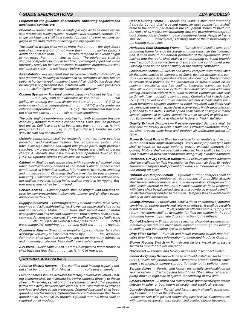
GUIDE SPECIFICATIONS LCA MODELS
Prepared for the guidance of architects, consulting engineers andmechanical contractors.
General — Furnish and install a single package air to air direct expan-sion mechanical cooling system, complete with automatic controls. Thesingle package unit shall be a standard product of a firm regularly en-gaged in the manufacture of heating-cooling equipment.
The installed weight shall not be more than . . . . . . . . lbs. (kg). Entireunit shall have a width of not more than . . . . . . . . inches (mm), adepth of not more than . . . . . . . . inches (mm) and an overall heightof not more than . . . . . . . .inches (mm). The equipment shall beshipped completely factory assembled, precharged, piped and wiredinternally ready for field connections. In addition, manufacturer shalltest operate system at the factory before shipment.
Air Distribution — Equipment shall be capable of bottom (down-flo) orside (horizontal) handling of conditioned air. Horizontal air shall requireoptional horizontal roof mounting frame. All air distribution ducts shallbe fiberglass or galvanized steel insulated with . . . . . . . . inch (mm) thick. . . . . . . . lb./ft.3 (kg/m3) density fiberglass or equivalent.
Cooling System — The total cooling capacity shall not be less than. . . . . . . . Btuh (kW) with an evaporator air volume of . . . . . . . . cfm(m3/s), an entering wet bulb air temperature of . . . . . . . . �F (�C), anentering dry bulb air temperature of . . . . . . . . �F (�C) and a condenserentering temperature of . . . . . . . . �F (�C). The compressor power in-put shall not exceed . . . . . . . . kW at these conditions.
The coils shall be non-ferrous construction with aluminum fins me-chanically bonded to durable copper tubes. Coils shall be pressureleak tested. Coil face area shall be not less than . . . . . . . . sq. ft. (m2)(evaporator) and . . . . . . . .sq. ft. (m2) (condenser). Condenser coilsshall be slab coil construction.
Multiple compressors shall be resiliently mounted, have overloadprotection and crankcase heaters. The refrigeration system shallhave discharge suction and liquid line gauge ports, high pressureswitches, low pressure switches, driers, freezestat and full refrigerantcharge. All models shall have low ambient operation down to 15�F(–9.4�C). Optional service valves shall be available.
Cabinet — Shall be galvanized steel with a powdered enamel paintfinish electrostatically bonded to the metal. Cabinet panels whereconditioned air is handled shall be fully insulated to prevent sweatingand minimize sound. Openings shall be provided for power connec-tion entry. Evaporator coil condensate drain extended outside cabi-net shall be provided. Lifting holes shall be provided for rigging. Bot-tom power entry shall be furnished.
Service Access — Cabinet panels shall be hinged with tool-less ac-cess for compressor/heating/controls, blower and air filter/ econo-mizer compartments.
Supply Air Blowers — Centrifugal supply air blower shall have sleevebearings and adjustable belt drive. Blower assembly shall slide out ofunit for servicing. Motor mount base shall permit ease of motorchangeover and belt tension adjustment. Blower wheel shall be stati-cally and dynamically balanced. Blower shall be capable of delivering. . . . . . . . cfm (m3/s) at an external static pressure of . . . . . . . .incheswater gauge (Pa) requiring . . . . . . . . bhp (kW) and . . . . . . . . rev/min.
Condenser Fans — Direct drive propeller type condenser fans shalldischarge vertically and be direct driven by a . . . . . . . . hp (W) motor.Fan motor shall have ball bearings and be permanently lubricatedand inherently protected. Fans shall have a safety guard.
Air Filters — Disposable 2 inch (51 mm) thick pleated filters furnishedshall have not less than . . . . . . . .sq. ft. (m2) of free area.
OPTIONAL ACCESSORIES
Additive Electric Heaters — The certified total heating capacity out-put shall be . . . . . . . . Btuh (kW) at . . . . . . . . volts power supply.
Electric heaters shall be available for factory or field installation. Heat-ing elements shall be nichrome bare wire exposed directly to the airstream. Time delays shall bring the elements on and off in sequencewith a time delay between each element. Limit controls shall provideoverload and short circuit protection. Optional fuse block shall be re-quired on electric heaters. Optional heater control module shall be re-quired on 45, 60 and 90 kW models. Optional terminal block shall berequired on all models.
Roof Mounting Frame — Furnish and install a steel roof mountingframe for bottom discharge and return air duct connection. It shallmate to the bottom perimeter of the equipment. When flashed intothe roof it shall make a unit mounting curb and provide weatherproofduct connection and entry into the conditioned area. Height of frameshall be . . . . . . . .inches (mm). Flashing shall be the responsibility ofthe roofing contractor.
Horizontal Roof Mounting Frame — Furnish and install a steel roofmounting frame for side discharge and unit return air duct connec-tion. It shall mate to the bottom perimeter of the equipment. Whenflashed into the roof it shall make a unit mounting curb and provideweatherproof duct connection and entry into the conditioned area.Flashing shall be the responsibility of the roofing contractor.
Economizer Section — Furnish and install complete with recirculatedair dampers, outside air dampers, air filters, damper actuator and con-trols. Low leakage dampers shall ride in nylon bearings. The economiz-er section shall provide for the introduction of 100% outdoor air forminimum ventilation and free cooling. Integrated economizer cycleshall allow compressors to cycle for dehumidification and additionalcooling, as needed, with 100% outdoor air intake. Damper actuator shallbe 24 volt, fully modulating spring return. Controls shall include fixed55�F (13�C) mixed air controller, damper actuator and adjustable mini-mum positioner. Optional outdoor air hood (required) with filters shallbe galvanized steel with a powdered enamel paint finish electrostatical-ly bonded to the metal. Control option shall consist of single enthalpycontrol, differential enthalpy control (return air sensor) or global con-trol. Economizer shall be available for factory or field installation.
Gravity Exhaust Dampers — Pressure operated dampers shall beavailable for factory or field installation. Extruded aluminum damp-ers shall prevent blow-back and outdoor air infiltration during offcycle.
Power Exhaust Fans — Shall be available for all models with econo-mizer (down-flow applications only). Direct drive propeller type fansshall exhaust air through optional gravity exhaust dampers (re-quired). Motors shall be overload protected. Fans shall be factory orfield installed in-between economizer and gravity exhaust dampers.
Horizontal Gravity Exhaust Dampers — Pressure operated dampersshall be available for field installation in the return air duct. Extrudedaluminum dampers shall prevent blow-back and outdoor air infiltra-tion during off cycle.
Outdoor Air Damper Section — Optional outdoor dampers shall beavailable to provide outdoor air requirements of up to 25%. Modelsshall be available for manual or automatic operation. Damper sectionshall install internal to the unit. Optional outdoor air hood (required)with filters shall be galvanized steel with a powdered enamel paint fin-ish electrostatically bonded to the metal. Dampers shall be available forfactory or field installation.
Ceiling Diffusers — Furnish and install a (flush or stepdown) optionalcombination ceiling supply and return air diffuser. It shall be capableof not less than . . . . . . . . ft. (m) radius of effective throw. Supply andreturn transitions shall be available, for field installation in the roofmounting frame, to provide duct connection to the diffuser.
Control Systems — Shall provide a selection of control systems to au-tomatically operate the mechanical equipment through the heatingor cooling and ventilating cycles as required.
Dirty Filter Switch — Furnish and install pressure switch that indi-cates dirty filter, relays information to Integrated Modular Control.
Blower Proving Switch — Furnish and factory install air pressureswitch to monitor blower operation.
Disconnect — Furnish and factory install unit disconnect switch.
Indoor Air Quality Sensor — Furnish and field install sensor to moni-tor CO2 levels, relays information to Integrated Module Control whichadjusts economizer dampers proportionately to the pollutant level.
Service Valves — Furnish and factory install fully serviceable brassservice valves in discharge and liquid lines. Shall allow refrigerantpump down to high side of system for servicing of low side.
Smoke Detectors — Furnish and factory install photoelectric type smokedetector in either or both return air section and supply air section.
Corrosion Protection — Furnish and factory apply phenolic epoxy coat-ing to either or both of the following:Condenser coils with painted condensing base section. Evaporator coilwith painted evaporator base section and painted blower housings.
— 44 —
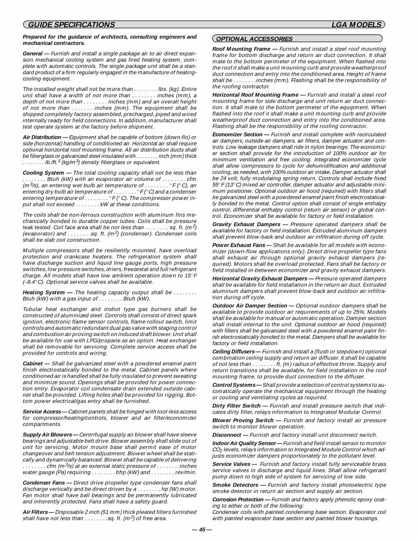
GUIDE SPECIFICATIONS LGA MODELS
Prepared for the guidance of architects, consulting engineers andmechanical contractors.
General — Furnish and install a single package air to air direct expan-sion mechanical cooling system and gas fired heating system, com-plete with automatic controls. The single package unit shall be a stan-dard product of a firm regularly engaged in the manufacture of heating-cooling equipment.
The installed weight shall not be more than . . . . . . . . lbs. (kg). Entireunit shall have a width of not more than . . . . . . . . inches (mm), adepth of not more than . . . . . . . . inches (mm) and an overall heightof not more than . . . . . . . .inches (mm). The equipment shall beshipped completely factory assembled, precharged, piped and wiredinternally ready for field connections. In addition, manufacturer shalltest operate system at the factory before shipment.
Air Distribution — Equipment shall be capable of bottom (down-flo) orside (horizontal) handling of conditioned air. Horizontal air shall requireoptional horizontal roof mounting frame. All air distribution ducts shallbe fiberglass or galvanized steel insulated with . . . . . . . . inch (mm) thick. . . . . . . . lb./ft.3 (kg/m3) density fiberglass or equivalent.
Cooling System — The total cooling capacity shall not be less than. . . . . . . . Btuh (kW) with an evaporator air volume of . . . . . . . . cfm(m3/s), an entering wet bulb air temperature of . . . . . . . . �F (�C), anentering dry bulb air temperature of . . . . . . . . �F (�C) and a condenserentering temperature of . . . . . . . . �F (�C). The compressor power in-put shall not exceed . . . . . . . . kW at these conditions.
The coils shall be non-ferrous construction with aluminum fins me-chanically bonded to durable copper tubes. Coils shall be pressureleak tested. Coil face area shall be not less than . . . . . . . . sq. ft. (m2)(evaporator) and . . . . . . . .sq. ft. (m2) (condenser). Condenser coilsshall be slab coil construction.
Multiple compressors shall be resiliently mounted, have overloadprotection and crankcase heaters. The refrigeration system shallhave discharge suction and liquid line gauge ports, high pressureswitches, low pressure switches, driers, freezestat and full refrigerantcharge. All models shall have low ambient operation down to 15�F(–9.4�C). Optional service valves shall be available.
Heating System — The heating capacity output shall be . . . . . . . .Btuh (kW) with a gas input of . . . . . . . . Btuh (kW).
Tubular heat exchanger and inshot type gas burners shall beconstructed of aluminized steel. Controls shall consist of direct sparkignition, electronic flame sensor controls, flame rollout switch, limitcontrols and automatic redundant dual gas valve with staging controland combustion air proving switch on induced draft blower. Unit shallbe available for use with LPG/propane as an option. Heat exchangershall be removable for servicing. Complete service access shall beprovided for controls and wiring.
Cabinet — Shall be galvanized steel with a powdered enamel paintfinish electrostatically bonded to the metal. Cabinet panels whereconditioned air is handled shall be fully insulated to prevent sweatingand minimize sound. Openings shall be provided for power connec-tion entry. Evaporator coil condensate drain extended outside cabi-net shall be provided. Lifting holes shall be provided for rigging. Bot-tom power electrical/gas entry shall be furnished.
Service Access — Cabinet panels shall be hinged with tool-less accessfor compressor/heating/controls, blower and air filter/economizercompartments.
Supply Air Blowers — Centrifugal supply air blower shall have sleevebearings and adjustable belt drive. Blower assembly shall slide out ofunit for servicing. Motor mount base shall permit ease of motorchangeover and belt tension adjustment. Blower wheel shall be stati-cally and dynamically balanced. Blower shall be capable of delivering. . . . . . . . cfm (m3/s) at an external static pressure of . . . . . . . .incheswater gauge (Pa) requiring . . . . . . . . bhp (kW) and . . . . . . . . rev/min.
Condenser Fans — Direct drive propeller type condenser fans shalldischarge vertically and be direct driven by a . . . . . . . . hp (W) motor.Fan motor shall have ball bearings and be permanently lubricatedand inherently protected. Fans shall have a safety guard.
Air Filters — Disposable 2 inch (51 mm) thick pleated filters furnishedshall have not less than . . . . . . . .sq. ft. (m2) of free area.
OPTIONAL ACCESSORIES
Roof Mounting Frame — Furnish and install a steel roof mountingframe for bottom discharge and return air duct connection. It shallmate to the bottom perimeter of the equipment. When flashed intothe roof it shall make a unit mounting curb and provide weatherproofduct connection and entry into the conditioned area. Height of frameshall be . . . . . . . .inches (mm). Flashing shall be the responsibility ofthe roofing contractor.Horizontal Roof Mounting Frame — Furnish and install a steel roofmounting frame for side discharge and unit return air duct connec-tion. It shall mate to the bottom perimeter of the equipment. Whenflashed into the roof it shall make a unit mounting curb and provideweatherproof duct connection and entry into the conditioned area.Flashing shall be the responsibility of the roofing contractor.Economizer Section — Furnish and install complete with recirculatedair dampers, outside air dampers, air filters, damper actuator and con-trols. Low leakage dampers shall ride in nylon bearings. The economiz-er section shall provide for the introduction of 100% outdoor air forminimum ventilation and free cooling. Integrated economizer cycleshall allow compressors to cycle for dehumidification and additionalcooling, as needed, with 100% outdoor air intake. Damper actuator shallbe 24 volt, fully modulating spring return. Controls shall include fixed55�F (13�C) mixed air controller, damper actuator and adjustable mini-mum positioner. Optional outdoor air hood (required) with filters shallbe galvanized steel with a powdered enamel paint finish electrostatical-ly bonded to the metal. Control option shall consist of single enthalpycontrol, differential enthalpy control (return air sensor) or global con-trol. Economizer shall be available for factory or field installation.Gravity Exhaust Dampers — Pressure operated dampers shall beavailable for factory or field installation. Extruded aluminum dampersshall prevent blow-back and outdoor air infiltration during off cycle.Power Exhaust Fans — Shall be available for all models with econo-mizer (down-flow applications only). Direct drive propeller type fansshall exhaust air through optional gravity exhaust dampers (re-quired). Motors shall be overload protected. Fans shall be factory orfield installed in-between economizer and gravity exhaust dampers.Horizontal Gravity Exhaust Dampers — Pressure operated dampersshall be available for field installation in the return air duct. Extrudedaluminum dampers shall prevent blow-back and outdoor air infiltra-tion during off cycle.Outdoor Air Damper Section — Optional outdoor dampers shall beavailable to provide outdoor air requirements of up to 25%. Modelsshall be available for manual or automatic operation. Damper sectionshall install internal to the unit. Optional outdoor air hood (required)with filters shall be galvanized steel with a powdered enamel paint fin-ish electrostatically bonded to the metal. Dampers shall be available forfactory or field installation.Ceiling Diffusers — Furnish and install a (flush or stepdown) optionalcombination ceiling supply and return air diffuser. It shall be capableof not less than . . . . . . . . ft. (m) radius of effective throw. Supply andreturn transitions shall be available, for field installation in the roofmounting frame, to provide duct connection to the diffuser.Control Systems — Shall provide a selection of control systems to au-tomatically operate the mechanical equipment through the heatingor cooling and ventilating cycles as required.Dirty Filter Switch — Furnish and install pressure switch that indi-cates dirty filter, relays information to Integrated Modular Control.Blower Proving Switch — Furnish and factory install air pressureswitch to monitor blower operation.Disconnect — Furnish and factory install unit disconnect switch.Indoor Air Quality Sensor — Furnish and field install sensor to monitorCO2 levels, relays information to Integrated Module Control which ad-justs economizer dampers proportionately to the pollutant level.Service Valves — Furnish and factory install fully serviceable brassservice valves in discharge and liquid lines. Shall allow refrigerantpump down to high side of system for servicing of low side.Smoke Detectors — Furnish and factory install photoelectric typesmoke detector in return air section and supply air section.Corrosion Protection — Furnish and factory apply phenolic epoxy coat-ing to either or both of the following:Condenser coils with painted condensing base section. Evaporator coilwith painted evaporator base section and painted blower housings.
— 45 —

GUIDE SPECIFICATIONS LHA MODELS
Prepared for the guidance of architects, consulting engineers andmechanical contractors.
General — Furnish and install a single package air to air direct expan-sion mechanical heat pump system, complete with automatic controls.The single package unit shall be a standard product of a firm regularlyengaged in the manufacture of heating-cooling equipment.The installed weight shall not be more than . . . . . . . . lbs. (kg). Entireunit shall have a width of not more than . . . . . . . . inches (mm), adepth of not more than . . . . . . . . inches (mm) and an overall heightof not more than . . . . . . . .inches (mm). The equipment shall beshipped completely factory assembled, precharged, piped and wiredinternally ready for field connections. In addition, manufacturer shalltest operate system at the factory before shipment.Air Distribution — Equipment shall be capable of bottom (down-flo) orside (horizontal) handling of conditioned air. Horizontal air shall requireoptional horizontal roof mounting frame. All air distribution ducts shallbe fiberglass or galvanized steel insulated with . . . . . . . . inch (mm) thick. . . . . . . . lb./ft.3 (kg/m3) density fiberglass or equivalent.Cooling System — The total cooling capacity shall not be less than. . . . . . . . Btuh (kW) with an indoor coil air volume of . . . . . . . . cfm(m3/s), an entering wet bulb air temperature of . . . . . . . . �F (�C), an en-tering dry bulb air temperature of . . . . . . . . �F (�C) and a outdoor coilentering temperature of . . . . . . . . �F (�C). The compressor power in-put shall not exceed . . . . . . . . kW at these conditions.Heating System — The total heating capacity shall not be less than. . . . . . . . Btuh (kW) with an indoor coil air volume of . . . . . . . . cfm(m3/s), an entering dry bulb temperature of . . . . . . . . �F (�C) and anoutdoor coil entering air temperature of . . . . . . . . �F (�C). The totalcompressor power input shall not exceed . . . . . . . . kW at the aboveconditions.The coils shall be non-ferrous construction with aluminum fins me-chanically bonded to durable copper tubes. Coils shall be pressureleak tested. Coil face area shall be not less than . . . . . . . . sq. ft. (m2)(indoor coil) and . . . . . . . .sq. ft. (m2) (outdoor coil). Outdoor coilsshall be formed coil construction.Multiple compressors shall be resiliently mounted, have overloadprotection and crankcase heaters. The refrigeration system shallhave discharge suction and liquid line gauge ports, high pressureswitches, low pressure switches, driers, defrost control, check andexpansion valves, reversing valves, accumulators and full refrigerantcharge. All models shall have low ambient cooling operation downto 15�F (–9.4�C).Cabinet — Shall be galvanized steel with a powdered enamel paintfinish electrostatically bonded to the metal. Cabinet panels whereconditioned air is handled shall be fully insulated to prevent sweatingand minimize sound. Openings shall be provided for power connec-tion entry. Indoor coil condensate drain extended outside cabinetshall be provided. Lifting holes shall be provided for rigging. Bottompower entry shall be furnished.Service Access — Cabinet panels shall be hinged with tool-less accessfor compressor/heating/controls, blower and air filter/economizercompartments.Supply Air Blowers — Centrifugal supply air blower shall have sleevebearings and adjustable belt drive. Blower assembly shall slide out ofunit for servicing. Motor mount base shall permit ease of motorchangeover and belt tension adjustment. Blower wheel shall be stati-cally and dynamically balanced. Blower shall be capable of delivering. . . . . . . . cfm (m3/s) at an external static pressure of . . . . . . . .incheswater gauge (Pa) requiring . . . . . . . . bhp (kW) and . . . . . . . . rpm.Outdoor Coil Fans — Direct drive propeller type outdoor coil fansshall discharge vertically and be direct driven by a . . . . . . . . hp (W)motor. Fan motor shall have ball bearings and be permanently lubri-cated and inherently protected. Fans shall have a safety guard.Air Filters — Disposable 2 inch (51 mm) thick pleated filters furnishedshall have not less than . . . . . . . .sq. ft. (m2) of free area.
OPTIONAL ACCESSORIES
Supplemental Electric Heaters — The certified total heating capacityoutput shall be . . . . . . . . Btuh with . . . . . . . . kW input at . . . . . . . .volts power supply.Electric heaters shall be available for factory or field installation. Heatingelements shall be nichrome bare wire exposed directly to the air stream.Time delays shall bring the elements on and off in sequence with a timedelay between each element. Limit controls shall provide overload andshort circuit protection. Optional fuse block shall be required on electricheaters. Optional heater control module shall be required on 45, 60 and90 kW models. Optional terminal block shall be required on all models.
Roof Mounting Frame — Furnish and install a steel roof mountingframe for bottom discharge and return air duct connection. It shallmate to the bottom perimeter of the equipment. When flashed intothe roof it shall make a unit mounting curb and provide weatherproofduct connection and entry into the conditioned area. Height of frameshall be . . . . . . . .inches (mm). Flashing shall be the responsibility ofthe roofing contractor.
Horizontal Roof Mounting Frame — Furnish and install a steel roofmounting frame for side discharge and unit return air duct connec-tion. It shall mate to the bottom perimeter of the equipment. Whenflashed into the roof it shall make a unit mounting curb and provideweatherproof duct connection and entry into the conditioned area.Flashing shall be the responsibility of the roofing contractor.
Economizer Section — Furnish and install complete with recirculatedair dampers, outside air dampers, air filters, damper actuator and con-trols. Low leakage dampers shall ride in nylon bearings. The economiz-er section shall provide for the introduction of 100% outdoor air forminimum ventilation and free cooling. Integrated economizer cycleshall allow compressors to cycle for dehumidification and additionalcooling, as needed, with 100% outdoor air intake. Damper actuator shallbe 24 volt, fully modulating spring return. Controls shall include fixed55�F (13�C) mixed air controller, damper actuator and adjustable mini-mum positioner. Optional outdoor air hood (required) with filters shallbe galvanized steel with a powdered enamel paint finish electrostatical-ly bonded to the metal. Control option shall consist of single enthalpycontrol, differential enthalpy control (return air sensor) or global con-trol. Economizer shall be available for factory or field installation.
Gravity Exhaust Dampers — Pressure operated dampers shall beavailable for factory or field installation. Extruded aluminum dampersshall prevent blow-back and outdoor air infiltration during off cycle.
Power Exhaust Fans — Shall be available for all models with econo-mizer (down-flow applications only). Direct drive propeller type fansshall exhaust air through optional gravity exhaust dampers (re-quired). Motors shall be overload protected. Fans shall be factory orfield installed in-between economizer and gravity exhaust dampers.
Horizontal Gravity Exhaust Dampers — Pressure operated dampersshall be available for field installation in the return air duct. Extrudedaluminum dampers shall prevent blow-back and outdoor air infiltra-tion during off cycle.
Outdoor Air Damper Section — Optional outdoor dampers shall beavailable to provide outdoor air requirements of up to 25%. Modelsshall be available for manual or automatic operation. Damper sectionshall install internal to the unit. Optional outdoor air hood (required)with filters shall be galvanized steel with a powdered enamel paint fin-ish electrostatically bonded to the metal. Dampers shall be available forfactory or field installation.
Ceiling Diffusers — Furnish and install a (flush or stepdown) optionalcombination ceiling supply and return air diffuser. It shall be capableof not less than . . . . . . . . ft. (m) radius of effective throw. Supply andreturn transitions shall be available, for field installation in the roofmounting frame, to provide duct connection to the diffuser.
Control Systems — Shall provide a selection of control systems to au-tomatically operate the mechanical equipment through the heatingor cooling and ventilating cycles as required.
Dirty Filter Switch — Furnish and install pressure switch that indi-cates dirty filter, relays information to Integrated Modular Control.
Blower Proving Switch — Furnish and factory install air pressureswitch to monitor blower operation.
Disconnect — Furnish and factory install unit disconnect switch.
Indoor Air Quality Sensor — Furnish and field install sensor to monitorCO2 levels, relays information to Integrated Module Control which ad-justs economizer dampers proportionately to the pollutant level.
Smoke Detectors — Furnish and factory install photoelectric typesmoke detector in return air section and supply air section.
Corrosion Protection — Furnish and factory apply phenolic epoxy coat-ing to either or both of the following:Outdoor coils with painted outdoor base section. Indoor coil withpainted indoor base section and painted blower housings.
— 46 —
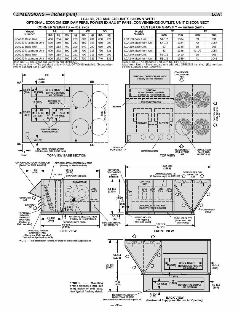
DIMENSIONS — inches (mm) LCALCA180, 210 AND 240 UNITS SHOWN WITH
OPTIONAL ECONOMIZER DAMPERS, POWER EXHAUST FANS, CONVENIENCE OUTLET, UNIT DISCONNECT
CORNER WEIGHTS — lbs. (kg)
ModelN b
AA BB CC DDNumber lbs. kg lbs. kg lbs. kg lbs. kg
LCA180 Base Unit 450 204 460 209 620 281 600 272LCA180 Maximum Unit 570 259 580 263 680 308 660 299LCA210 Base Unit 470 213 460 209 640 290 650 295LCA210 Maximum Unit 600 272 590 268 700 318 730 331LCA240 Base Unit 480 218 510 231 700 318 660 299LCA240 Maximum Unit 600 272 600 272 730 331 740 336
Base Unit — The standard unit with NO OPTIONS.Maximum Unit — The standard unit with ALL OPTIONS Installed. (Economizer,Power Exhaust Fans, Controls)
CENTER OF GRAVITY — inches (mm)
ModelN b
EE FFNumber inch mm inch mm
LCA180 Base Unit 54-1/2 1384 39 991LCA180 Maximum Unit 54-1/2 1384 42 1067LCA210 Base Unit 53 1346 38 965LCA210 Maximum Unit 53 1346 41-1/2 1054LCA240 Base Unit 55-1/2 1410 38 965LCA240 Maximum Unit 53-1/2 1359 41 1041
Base Unit — The standard unit with NO OPTIONS.Maximum Unit — The standard unit with ALL OPTIONS Installed. (Economizer,Power Exhaust Fans, Controls)
BLOWERS (2)
EVAPORATOR COIL
CONDENSERCOIL INTAKE
AIR
CONDENSERCOILS
BOTTOMPOWER ENTRY
FILTERS
CONDENSERCOIL INTAKE
AIR
COMPRESSORS
CONTROLBOX
CONDENSER COILEXHAUST
AIR
CONDENSERFANS AND
GUARDS (4)
BLOWER
EVAPORATOR COIL
FILTERS
BLOWER
FRONT VIEW
TOP VIEW
SIDE VIEW
90-1/8(2289)
31-1/2(800)
91-1/8(2315)
3-1/4(83)
107-1/4(2724)
132-5/8(3369)
54-1/4(1378)
51(1295)
LIFTING HOLES(For Rigging
Front and Back)
BOTTOM POWER ENTRY5 X 8 inches (127 X 203 mm)
BOTTOM SUPPLYAIR OPENINGS
TOP VIEW BASE SECTION
CO
IL
OV
ER
HA
NG
BOTTOM RETURNAIR OPENING
4-1/4(108)
4-1/2(114)
28(711)
28(711)
4 (102)
4(102)
12-3/8(314)
12-3/8(314) 20 (508) 20 (508)
15 (381)
18 (457)
60-1/2 (1537)
16(406)
CONDENSATE DRAIN
1/2(13)
CO
ND
EN
SE
RC
OIL
IN
TA
KE
AIR
BACK VIEW(Horizontal Supply and Return Air Opening)
HORIZONTAL SUPPLYAIR OPENING
HORIZONTAL ROOFMOUNTING FRAME
(Required For Horizontal Supply Air)
15-1/4(387)
75(1905)14 (356)
6-1/2(165)
OUTDOORAIR
OPTIONAL ECONOMIZER DAMPERS(Factory or Field Installed)
OPTIONALECONOMIZER DAMPERS(Factory or Field Installed)
COMPRESSORS (4)(3 Compressors on LCA180)
FORKLIFT SLOTS(Front and Left
Sides Only)
OPTIONAL ELECTRIC HEAT(Factory or Field Installed)
OPTIONALDISCONNECT
(FieldInstalled)
SIDE ELECTRICALKNOCKOUTS
5-3/8(137)
OPTIONAL ELECTRIC HEAT(Factory or Field Installed)
HORIZONTAL RETURNAIR OPENING
12-3/8(314)
15 (381)60-1/2 (1537)
2 (51)
**20(508)
54-1/4(1378)
76-1/4(1937)
EXHAUSTAIR
*NOTE — Field Installed in Return Air Duct for Horizontal Applications.
OPTIONAL POWEREXHAUST FANS
(Factory or Field Installed)Down-flow Applications Only
*OPTIONALGRAVITYEXHAUSTDAMPERS(Factory or
Field Installed)
OPTIONAL OUTDOOR AIR HOOD(Factory or Field Installed)
**NOTE — MountingFrame extends 4 inch (102mm) inside of unit base.See Typical flashing detail.
OPTIONAL OUTDOOR AIR HOOD(Factory or Field Installed)
AA BB
CCDD
CENTER OFGRAVITY
EE
FF
— 47 —
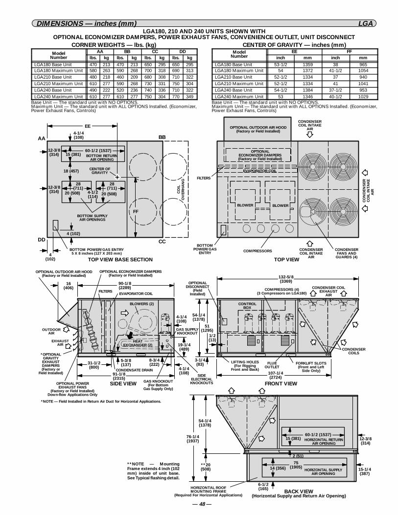
DIMENSIONS — inches (mm) LGALGA180, 210 AND 240 UNITS SHOWN WITH
OPTIONAL ECONOMIZER DAMPERS, POWER EXHAUST FANS, CONVENIENCE OUTLET, UNIT DISCONNECT
CORNER WEIGHTS — lbs. (kg)
Model AA BB CC DDModelNumber lbs. kg lbs. kg lbs. kg lbs. kg
LGA180 Base Unit 470 213 470 213 650 295 650 295LGA180 Maximum Unit 580 263 590 268 700 318 690 313LGA210 Base Unit 480 218 460 209 680 308 710 322LGA210 Maximum Unit 610 277 590 268 730 331 750 304LGA240 Base Unit 490 222 520 236 740 336 710 322LGA240 Maximum Unit 610 277 610 277 750 304 770 349
Base Unit — The standard unit with NO OPTIONS.Maximum Unit — The standard unit with ALL OPTIONS Installed. (Economizer,Power Exhaust Fans, Controls)
CENTER OF GRAVITY — inches (mm)
ModelN b
EE FFNumber inch mm inch mm
LGA180 Base Unit 53-1/2 1359 38 965LGA180 Maximum Unit 54 1372 41-1/2 1054LGA210 Base Unit 52-1/2 1334 37 940LGA210 Maximum Unit 52-1/2 1334 41 1041LGA240 Base Unit 54-1/2 1384 37-1/2 953LGA240 Maximum Unit 53 1346 40-1/2 1029
Base Unit — The standard unit with NO OPTIONS.Maximum Unit — The standard unit with ALL OPTIONS Installed. (Economizer,Power Exhaust Fans, Controls)
HEATEXCHANGER (2)
BLOWERS (2)
COMPRESSORS (4)(3 Compressors on LGA180)EVAPORATOR COIL
CONDENSERCOIL INTAKE
AIR
CONDENSERCOILS
BOTTOMPOWER/GAS
ENTRY
FILTERS
CONDENSERCOIL INTAKE
AIR
COMPRESSORS
CONTROLBOX
CONDENSER COILEXHAUST
AIR
CONDENSERFANS AND
GUARDS (4)
BLOWER
EVAPORATOR COIL
FILTERS
BLOWER
FRONT VIEW
TOP VIEW
SIDE VIEW
FORKLIFT SLOTS(Front and Left
Side Only)
OUTDOORAIR
EXHAUSTAIR
90-1/8(2289)
31-1/2(800)
91-1/8(2315)
4-1/4(108)
19-1/4(489)
3-1/4(83)
107-1/4(2724)
132-5/8(3369)
54-1/4(1378)
51(1295)
LIFTING HOLES(For Rigging
Front and Back)
BOTTOM POWER/GAS ENTRY5 X 8 inches (127 X 203 mm)
BOTTOM SUPPLYAIR OPENINGS
TOP VIEW BASE SECTION
CO
IL
OV
ER
HA
NG
BOTTOM RETURNAIR OPENING
4-1/4(108)
4-1/2(114)
28(711)
28(711)
4 (102)
4(102)
12-3/8(314)
12-3/8(314) 20 (508) 20 (508)
15 (381)
18 (457)
60-1/2 (1537)
OPTIONAL ECONOMIZER DAMPERS(Factory or Field Installed)
16(406)
4-1/4(108)
GAS SUPPLYKNOCKOUT
8-3/4(222)
CONDENSATE DRAIN
1/2(13)
5-3/8(137)
CO
ND
EN
SE
RC
OIL
IN
TA
KE
AIR
BACK VIEW(Horizontal Supply and Return Air Opening)
HORIZONTAL SUPPLYAIR OPENING
HORIZONTAL ROOFMOUNTING FRAME
(Required For Horizontal Applications)
**20(508) 15-1/4
(387)
75(1905)14 (356)
6-1/2(165)
OPTIONAL OUTDOOR AIR HOOD(Factory or Field Installed)
OPTIONALECONOMIZER DAMPERS(Factory or Field Installed)
SIDEELECTRICALKNOCKOUTSGAS KNOCKOUT
(For BottomGas Supply Only)
OPTIONALDISCONNECT
(FieldInstalled)
HORIZONTAL RETURNAIR OPENING
12-3/8(314)
15 (381)60-1/2 (1537)
2 (51)
54-1/4(1378)
76-1/4(1937)
**NOTE — MountingFrame extends 4 inch (102mm) inside of unit base.See Typical flashing detail.
*NOTE — Field Installed in Return Air Duct for Horizontal Applications.
OPTIONAL POWEREXHAUST FANS
(Factory or Field Installed)Down-flow Applications Only
*OPTIONALGRAVITYEXHAUSTDAMPERS(Factory or
Field Installed)
OPTIONAL OUTDOOR AIR HOOD(Factory or Field Installed)
FLUEOUTLET
AA BB
CCDD
CENTER OFGRAVITY
EE
FF
— 48 —
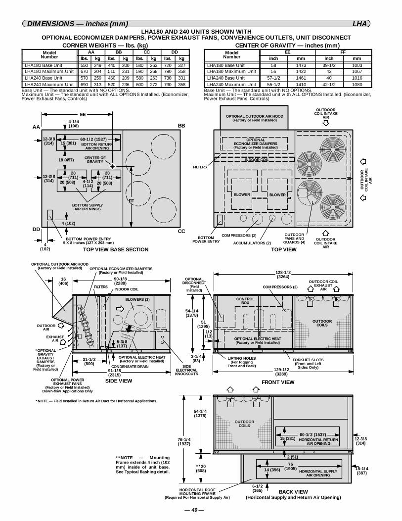
DIMENSIONS — inches (mm) LHALHA180 AND 240 UNITS SHOWN WITH
OPTIONAL ECONOMIZER DAMPERS, POWER EXHAUST FANS, CONVENIENCE OUTLETS, UNIT DISCONNECT
CORNER WEIGHTS — lbs. (kg)
ModelN b
AA BB CC DDNumber lbs. kg lbs. kg lbs. kg lbs. kg
LHA180 Base Unit 550 249 440 200 580 263 720 327LHA180 Maximum Unit 670 304 510 231 590 268 790 358LHA240 Base Unit 570 259 460 209 580 263 730 331LHA240 Maximum Unit 690 313 520 236 600 272 790 358
Base Unit — The standard unit with NO OPTIONS.Maximum Unit — The standard unit with ALL OPTIONS Installed. (Economizer,Power Exhaust Fans, Controls)
CENTER OF GRAVITY — inches (mm)
ModelN b
EE FFNumber inch mm inch mm
LHA180 Base Unit 58 1473 39-1/2 1003LHA180 Maximum Unit 56 1422 42 1067LHA240 Base Unit 57-1/2 1461 40 1016LHA240 Maximum Unit 55-1/2 1410 42-1/2 1080
Base Unit — The standard unit with NO OPTIONS.Maximum Unit — The standard unit with ALL OPTIONS Installed. (Economizer,Power Exhaust Fans, Controls)
BLOWERS (2)
COMPRESSORS (2)INDOOR COIL
OUTDOORCOIL INTAKE
AIR
OUTDOORCOILS
BOTTOMPOWER ENTRY
FILTERS
OUTDOORCOIL INTAKE
AIR
COMPRESSORS (2)
CONTROLBOX
OUTDOOR COILEXHAUST
AIR
OUTDOORFANS AND
GUARDS (4)
BLOWER
INDOOR COIL
FILTERS
BLOWER
FRONT VIEW
TOP VIEW
SIDE VIEW
90-1/8(2289)
31-1/2(800)
91-1/8(2315)
3-1/4(83)
129-1/2(3289)
128-1/2(3264)
54-1/4(1378)
51(1295)
LIFTING HOLES(For Rigging
Front and Back)
BOTTOM POWER ENTRY5 X 8 inches (127 X 203 mm)
BOTTOM SUPPLYAIR OPENINGS
TOP VIEW BASE SECTION
BOTTOM RETURNAIR OPENING
4-1/4(108)
4-1/2(114)
28(711)
28(711)
4 (102)
4(102)
12-3/8(314)
12-3/8(314) 20 (508) 20 (508)
15 (381)
18 (457)
60-1/2 (1537)
16(406)
CONDENSATE DRAIN
1/2(13)
5-3/8(137)
OU
TD
OO
RC
OIL
IN
TA
KE
AIR
ACCUMULATORS (2)
OPTIONALDISCONNECT
(FieldInstalled)
SIDEELECTRICALKNOCKOUTS
OUTDOORAIR
OPTIONAL ECONOMIZER DAMPERS(Factory or Field Installed)
OPTIONALECONOMIZER DAMPERS(Factory or Field Installed)
FORKLIFT SLOTS(Front and Left
Sides Only)
OPTIONAL ELECTRIC HEAT(Factory or Field Installed)
OPTIONAL ELECTRIC HEAT(Factory or Field Installed)
BACK VIEW(Horizontal Supply and Return Air Opening)
HORIZONTAL SUPPLYAIR OPENING
HORIZONTAL ROOFMOUNTING FRAME
(Required For Horizontal Supply Air)
**20(508)
15-1/4(387)
75(1905)14 (356)
6-1/2(165)
HORIZONTAL RETURNAIR OPENING
12-3/8(314)
15 (381)60-1/2 (1537)
2 (51)
OUTDOORCOILS
54-1/4(1378)
76-1/4(1937)
OPTIONAL OUTDOOR AIR HOOD(Factory or Field Installed)
OPTIONAL OUTDOOR AIR HOOD(Factory or Field Installed)
EXHAUSTAIR
*NOTE — Field Installed in Return Air Duct for Horizontal Applications.
OPTIONAL POWEREXHAUST FANS
(Factory or Field Installed)Down-flow Applications Only
*OPTIONALGRAVITYEXHAUSTDAMPERS(Factory or
Field Installed)
**NOTE — MountingFrame extends 4 inch (102mm) inside of unit base.See Typical flashing detail.
AA BB
CCDD
CENTER OFGRAVITY
EE
FF
— 49 —
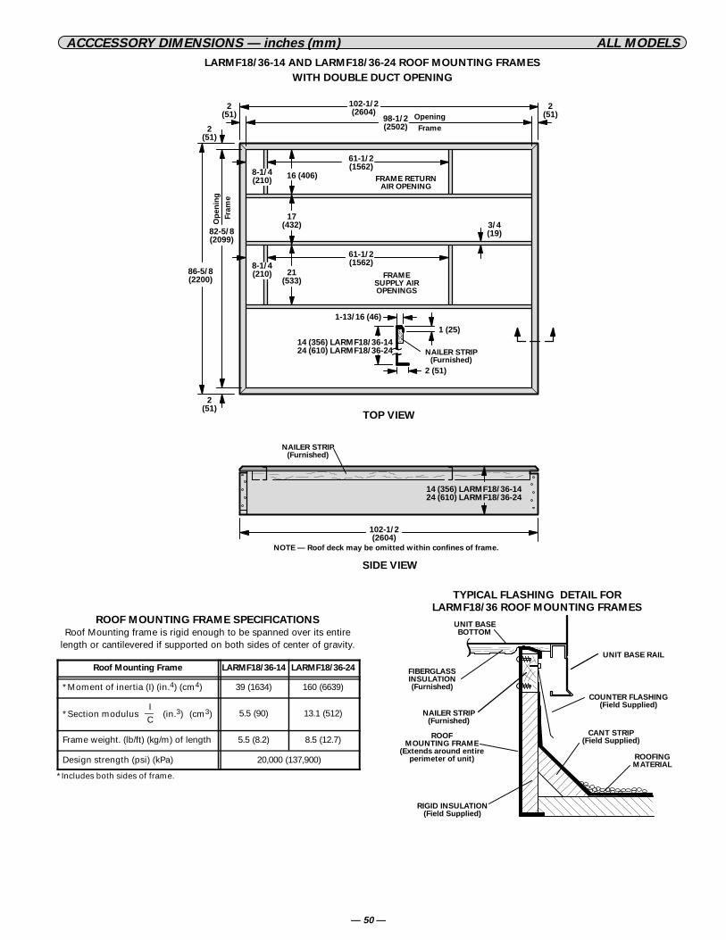
ACCCESSORY DIMENSIONS — inches (mm) ALL MODELS
LARMF18/36-14 AND LARMF18/36-24 ROOF MOUNTING FRAMES
WITH DOUBLE DUCT OPENING
1 (25)
2 (51)
1-13/16 (46)
NOTE — Roof deck may be omitted within confines of frame.
SIDE VIEW
NAILER STRIP(Furnished)
14 (356) LARMF18/36-1424 (610) LARMF18/36-24
FRAME RETURNAIR OPENING
FRAMESUPPLY AIROPENINGS
TOP VIEW
Fra
me
Op
en
ing
Frame
Opening
17(432)
21(533)
16 (406)
102-1/2(2604)
8-1/4(210)
61-1/2(1562)
61-1/2(1562)
8-1/4(210)
98-1/2(2502)
86-5/8(2200)
82-5/8(2099)
102-1/2(2604)
2(51)
2(51)
2(51)
2(51)
NAILER STRIP(Furnished)
3/4(19)
14 (356) LARMF18/36-1424 (610) LARMF18/36-24
ROOF MOUNTING FRAME SPECIFICATIONS
Roof Mounting frame is rigid enough to be spanned over its entirelength or cantilevered if supported on both sides of center of gravity.
Roof Mounting Frame LARMF18/36-14 LARMF18/36-24
*Moment of inertia (I) (in.4) (cm4) 39 (1634) 160 (6639)
*Section modulusI
—C
(in.3) (cm3) 5.5 (90) 13.1 (512)
Frame weight. (lb/ft) (kg/m) of length 5.5 (8.2) 8.5 (12.7)
Design strength (psi) (kPa) 20,000 (137,900)
*Includes both sides of frame.
TYPICAL FLASHING DETAIL FOR
LARMF18/36 ROOF MOUNTING FRAMES
ROOFMOUNTING FRAME
(Extends around entireperimeter of unit)
FIBERGLASSINSULATION(Furnished)
COUNTER FLASHING(Field Supplied)
UNIT BASEBOTTOM
RIGID INSULATION(Field Supplied)
ROOFINGMATERIAL
CANT STRIP(Field Supplied)
NAILER STRIP(Furnished)
UNIT BASE RAIL
— 50 —

1 (25)
2 (51)SECTION A-A
1-13/16 (46)
SIDE VIEW
NAILER STRIP(Furnished)
RETURNAIR OPENING
SUPPLY AIROPENINGS
TOP VIEW
Fra
me
Op
en
ing
Frame
Opening
54(1372)
102-1/2 (2604)
69-1/4(1759)
98-1/2(2502)
86-5/8(2200)
82-5/8(2099)
102-1/2 (2604)
2(51)
2 (51)
AANAILER STRIP
(Furnished)
3/4(19)
Typ.
4-1/2(114)
LASRT RETURN TRANSITION
LASRT SUPPLY TRANSITION
SUPPORTANGLE
(Furnishedwith
Transitions)
INSULATION(Furnished)
2(51)
10(254)
8 (203)
A
B
B
A
14 (356) LARMF18/36-1424 (610) LARMF18/36-24
14 (356) LARMF18/36-1424 (610) LARMF18/36-24
A
B
69-1/4(1759)
2(51)
8 (203)
26-1/2(673)
1-1/2(38)
Typ.
TRANSITION OPENING SIZES
NOTE — Roof deck may be omitted within confines of frame.
SIDE VIEW
TOP VIEW
Fra
me
Op
en
ing
Frame
Opening
54(1372)
102-1/2 (2604)
98-1/2(2502)
86-5/8(2200)
82-5/8(2099)
86-5/8 (2200)
98-1/2(2502)
FRONT VIEW
NAILER STRIP(Furnished)
26(660)
102-1/2 (2604)
FRAME SUPPLYAIR OPENING
With 1-1/2 in. (38 mm) FLANGE
15-1/4(387)
8-1/4(210)
75(1905)
6-1/2 (165)
5-1/2 (140)
14 (356)SUPPLYDUCT
PANELS(Furnished)
SUPPLY AIRTURNING
VANE(Furnished)
1 (25)
2 (51)SECTION A-A
1-13/16 (46)
NAILER STRIP(Furnished)
26(660)
AA
102-1/8 (2594)
86-1/4(2191)
NOTE — Roof deck may beomitted within confines of frame.
LARMFH18/24 HORIZONTAL ROOF MOUNTING FRAME
2 (51)
2 (51)
2 (51)2 (51)
2 (51)
2 (51)
TRANSITION DETAIL
SUPPLY AIRTURNING
VANE(Furnished)
PANEL TO COVER RETURN AIROPENING IN BOTTOM OF UNIT(Furnished With LARMFH18/24)
SIDE VIEW(PACKAGED UNIT)
ACCCESSORY DIMENSIONS — inches (mm) ALL MODELSLARMF18/36-14 AND LARMF18/36-24 ROOF MOUNTING FRAMES WITH
LASRT SUPPLY & RETURN AIR TRANSITIONS FOR FD11 & RTD11 CEILING DIFFUSERS
ModelA B
ModelNumber inch mm inch mm
LASRT18 18 457 36 914
LASRT21/24 24 610 48 1219
— 51 —

ACCCESSORY DIMENSIONS — inches (mm) ALL MODELS
COMBINATION CEILING SUPPLY AND RETURN DIFFUSERS
2 (51)2 (51)
AB
C
D
E
F G
A
B
C
D
E
RTD11-185 & RTD11-275STEP-DOWN CEILING DIFFUSER
FD11-185 & FD11-275FLUSH CEILING DIFFUSER
HH
J
K
FF
G
H
ModelN b
A B C D E
Number in. mm in. mm in. mm in. mm in. mm
RTD11-185 34 864 23-7/8 606 10-1/8 257 47-5/8 1210 45-5/8 1159
RTD11-275 40 1016 28-7/8 225 11-1/8 283 59-5/8 1514 57-7/8 1470
ModelN
F G H J K
Number in. mm in. mm in. mm in. mm in. mm
RTD11-185 36 914 4-13/16 122 18 457 45-5/8 1159 47-5/8 1210
RTD11-275 48 1219 4-13/16 122 24 610 57-5/8 1464 59-5/8 1521
Model A B C D
Number in. mm in. mm in. mm in. mm
FD11-185 30-1/8 613 47-5/8 1210 45-5/8 1159 36 914
FD11-275 36-1/8 918 59-5/8 1514 57-5/8 1464 48 1219
Model E F G H
Number in. mm in. mm in. mm in. mm
FD11-185 4-13/16 122 18 457 45-5/8 1159 47-5/8 1210
FD11-275 4-13/16 122 24 610 57-5/8 1464 59-5/8 1521
LAGEDH18/24 HORIZONTAL GRAVITY EXHAUST DAMPERS
(Two Furnished Per Order Number)
Field Installed In Return Air Duct
SIDE VIEW
31-5/8 (803)
14-1/2(368)
*13(330)
6-1/2(165)*29-1/2 (749)
*NOTE — Opening size required in return air duct.
FRONT VIEW
INSTALLATION CLEARANCES — inches (mm)
OUTDOORAIR HOOD
36 (914)
36(914)
45 (1143)
*41(1041)
NOTE — Top Clearance Unobstructed.NOTE — Entire perimeter of unit base
requires support when elevatedabove mounting surface.
*66 in. (1676 mm)Recommended
serviceclearance for
blower deck removal
— 52 —