engineering design guidelines constructed lakes · a primary consideration for constructed lakes is...
TRANSCRIPT

ENGINEERING DESIGN GUIDELINES
CONSTRUCTED LAKES
Planning Scheme Policy No. 15.15
DATE POLICY TOOK EFFECT:
31 March 2008
Engineering Design Guidelines Planning Scheme Policy No. 15.15 Constructed Lakes FEBRUARY 2008 REVISION 1
1/46 Policy took effect on 31/03/08
MACKAY CITY COUNCIL PLANNING SCHEME POLICY
Engineering Design Guidelines Planning Scheme Policy No. 15.15 Constructed Lakes FEBRUARY 2008 REVISION 1
2/46 Policy took effect on 31/03/08
Contents
1 Scope and General ......................................................................................................3 1.1 Scope...........................................................................................................................3 1.2 Objective ......................................................................................................................3 1.3 General ........................................................................................................................3 1.4 Terminology .................................................................................................................3 1.5 Reference and Source Documents ..............................................................................4
2 Planning and Concept Design Submission...................................................................7 2.1 General ........................................................................................................................7 2.2 Concept Design............................................................................................................7
3 Detailed Design, Construction and Maintenance Submission ......................................9 3.1 Detail Design................................................................................................................9 3.2 Construction.................................................................................................................9 3.3 Maintenance ..............................................................................................................10
4 Design Considerations ...............................................................................................11 4.1 General ......................................................................................................................11 4.2 Design Intent..............................................................................................................11 4.3 Legislative Requirements ...........................................................................................12 4.4 Recreation..................................................................................................................12 4.5 Setbacks ....................................................................................................................12 4.6 Amenity – Visual and Landscaping ............................................................................12 4.7 Lake Functional Design..............................................................................................12 4.8 Risk Management ......................................................................................................13 4.9 Monitoring ..................................................................................................................13 4.10 Maintenance ..............................................................................................................13 4.11 Cost ...........................................................................................................................13 4.12 Drawings and Documentation ....................................................................................13
A Constructed Lake Design Considerations ..................................................................15
B Constructed Lake Functional Design Process............................................................25
C Water Level Variation.................................................................................................42

MACKAY CITY COUNCIL PLANNING SCHEME POLICY
Engineering Design Guidelines Planning Scheme Policy No. 15.15 Constructed Lakes FEBRUARY 2008 REVISION 1 3/46
Policy took effect on 31/03/08
1 Scope and General 1.1 Scope
This document sets out guidelines for the design of constructed lakes proposed within Mackay City.
A well-designed and sustainable lake system can add substantial value to the urban landscape. Lakes are primarily created for their visual amenity however they can also provide wildlife habitat and allow the community to understand, experience and engage with the water cycle.
However, experience throughout Queensland has identified numerous problems with the sustainability of lake systems. The use of lakes as stormwater treatment systems, poor water inflows, long residence times, lower abundance of emergent macrophytes and inadequate mixing (stratification) have resulted in lake systems experiencing algal blooms and becoming weed infested. In many cases, the burden of rectifying these lakes systems and satisfying community expectations has been incurred by Councils. As a consequence Mackay City Council does not encourage the creation of constructed lakes in urban settings.
Whilst constructed lakes are not encouraged, Council will consider the application of a lake where it can be demonstrated the lake system is sustainable in terms of supporting the intended end uses, is appropriately managed and has minimal adverse impacts on surrounding environments.
1.2 Objective To ensure that lake systems in Mackay City are designed to ensure long term sustainability as landscape assets.
1.3 General A suitably qualified Registered Professional Engineer Queensland (RPEQ) with specific water sensitive urban design and lake design experience, must undertake or oversee all aspects of the constructed lake design. The design must comply with all relevant requirements of:
• this Guideline;
• Reference and Source Documents listed in Section 1.5;
• any Development Approval conditions relevant to the design; and
• any specific relevant and reasonable request provided by Council in writing.
The RPEQ shall sign all plans associated with the lake, certifying that the design complies with this section.
1.4 Terminology Constructed lake – an artificial body of permanent open water with either an edge that may be fringed with emergent macrophytes or a hard edge. While submerged macrophytes may occur throughout the water column, the dominant feature is open water.
MACKAY CITY COUNCIL PLANNING SCHEME POLICY
Engineering Design Guidelines Planning Scheme Policy No. 15.15 Constructed Lakes FEBRUARY 2008 REVISION 1 4/46
Policy took effect on 31/03/08
Constructed Wetland – are characteristically shallow (on average 0.3m) aquatic environments that support a range of aquatic vegetation across the majority of the waterbody area. The inlet zone of a constructed wetland may, for instance, resemble a pond, but the dominant feature of the system is the macrophyte zone, containing emergent marsh, rush and reed vegetation that requires or can withstand wetting and drying cycles. The structure of constructed wetland systems means they can remove pollutants from stormwater runoff through enhanced sedimentation, fine filtration and biological uptake (refer WSUD Technical Design Guidelines for SEQ for details).
Lake Catchment – An area of land bounded by natural features such as hills, from which all runoff flows into a lake.
Environmental Values (EVs) – Qualities or characteristics of a waterway that support healthy ecosystems and the communities livelihoods and lifestyle. Environmental Values are determined by community preference and reasonable judgement.
Natural Design Concept – A design which integrates well with the catchment hydrology and ecology, but also integrates well with the local community and the values the community place on their waterways/lakes etc.
Receiving Water – A water body that may receive runoff from the catchment under consideration, and has some environmental value of beneficial use. Natural wetlands are included in the definition of receiving waters, but constructed wetlands that have been built primarily for the purpose of stormwater (or wastewater) treatment, are not.
Sediment – Solids (typically sand, silt and mud) that are transported by water. Considered to be a ‘contaminant’ as defined in the Environmental Protection Act 1994.
Stormwater – Surface water runoff following a rain event (including piped flows).
Stormwater Quality Improvement Devices (SQIDs) – Devices used to improve the health of our waterways. SQIDs work by reducing the amounts of pollutants that enter stormwater and waterways. Types of SQIDs include trash racks, gross pollutant traps, constructed wetlands, gully pit baskets.
Water Quality Indicators – A water quality indicator is an indicator for an environmental value, and is a property that can be measured in a quantitative way (eg. pH, temperature).
Water Quality Modelling – A technique used to make predictions about the quality of water in waterways. Water quality modelling encompasses pollutant export modelling via models such as MUSIC and AQUALM, which predicts the pollutant loads being discharged from a given area.
Water Quality Objectives (WQOs) – Measurable goals for the quality of receiving waters to ensure the Environmental Values are protected.
Water Sensitive Urban Design (WSUD) – WSUD is a relatively new concept in regional Queensland, dealing with the ‘interactions between the urban built form (including urban landscapes) and the urban water cycle as defined by the three urban water streams being potable water, wastewater and stormwater’ (Engineers Australia 2003).
Waterway – Any element of a river, creek, stream, gully or drainage channel, including the bed and banks. This term includes waterways indicated on the Planning Scheme Maps.
1.5 Reference and Source Documents (a) Council Guidelines & Specifications
D5 Stormwater Drainage Design D7 Soil and Water Quality Management D20 Drawings and documentation Guidelines C273 Landscaping

MACKAY CITY COUNCIL PLANNING SCHEME POLICY
Engineering Design Guidelines Planning Scheme Policy No. 15.15 Constructed Lakes FEBRUARY 2008 REVISION 1 5/46
Policy took effect on 31/03/08
Stormwater Quality Management Plan for Mackay, 2006
Social and Recreational Plans and Studies
(b) QLD State Legislation
Environmental Protection Act 1994
Environmental Protection Regulation 1998
Environmental Protection (Water) Policy 1997
Integrated Planning Act 1997
State Planning Policy 2/02 Planning and Managing Development involving Acid Sulfate Soils
Coastal Protection and Management Act 1995
Coastal Protection and Management Regulation 2003
Fisheries Act 1994
Water Act 2000
Soil Conservation Act 1986
Vegetation Management Act 1999
Local Government Act 1993
(c) QLD State Authorities
Queensland Department of Natural Resources and Mines
Dam Safety Management Guidelines, 2002
Soil Management Guidelines in Queensland Acid Sulfate Soil
Technical Manual 2002
(d) Other
ANZECC
Australian Water Quality Guideline for Fresh and Marine Waters 2000
Australian Standards
AS/NZS 4360:2004 Risk management
Brisbane City Council (BCC)
Sediment Basin Design Guidelines 2001
Stormwater Outlets in Parks and Waterways, Guidelines, 2002
Natural Channel Design Guidelines, 2000
Guidelines for Pollutant Export Modelling in Brisbane, Version 7 – Draft 2003
Water Quality Management Guidelines, 2000
Water Sensitive Urban Design Engineering Guidelines: Stormwater 2006
MACKAY CITY COUNCIL PLANNING SCHEME POLICY
Engineering Design Guidelines Planning Scheme Policy No. 15.15 Constructed Lakes FEBRUARY 2008 REVISION 1 6/46
Policy took effect on 31/03/08
Cullen, E., Taylor, S., Leinster, S. and Eadie, M.
Design and management responses to address common constructed urbanlake sustainability issues
Burge, K., & Breen, P.F.
Detention time design criteria to reduce the risk of excessive algal growth inconstructed waterbodies, Proceeding from 7th International Conference onUrban Drainage Modelling, Melbourne 2006
Engineers Australia
Australian Runoff Quality 2006.
Institution of Engineers Australia, Queensland Division (IEAQ)
Soil Erosion and Sediment Control – Engineering Guidelines for Queensland Construction Sites, 1996
Healthy Waterways
WSUD Technical Design Guidelines for South East Queensland, 2006
Lawrence I and Breen P
Design Guidelines: Stormwater pollution control ponds and wetlands for theCooperative research Centre for Freshwater Ecology
Melbourne Water
Constructed Shallow Lake Systems, Design Guidelines for Developers,Version 2, November 2005
WSUD Engineering Procedures, 2005
MACKAY CITY COUNCIL PLANNING SCHEME POLICY
Engineering Design Guidelines Planning Scheme Policy No. 15.15 Constructed Lakes FEBRUARY 2008 REVISION 1 7/46
Policy took effect on 31/03/08
2 Planning and Concept Design Submission
2.1 General Developments proposing small constructed lakes need to demonstrate that the lakes will be
• consistent with the area’s social and recreational masterplans;
• sustainable;
• appropriately managed; and
• have minimal adverse impacts on surrounding environments.
A primary consideration for constructed lakes is that the lakes proposed “mimic nature”. Constructed lakes should be located in low lying areas of the catchment that are (or have been) connected to a waterway and have (or had) areas of ponded water such as billabongs/lagoons.
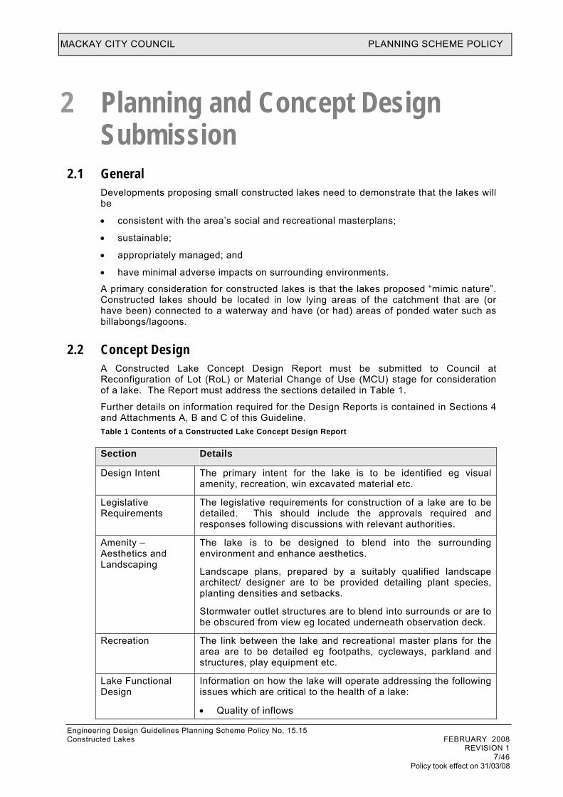
2.2 Concept Design A Constructed Lake Concept Design Report must be submitted to Council at Reconfiguration of Lot (RoL) or Material Change of Use (MCU) stage for consideration of a lake. The Report must address the sections detailed in Table 1.
Further details on information required for the Design Reports is contained in Sections 4 and Attachments A, B and C of this Guideline. Table 1 Contents of a Constructed Lake Concept Design Report
Section Details
Design Intent The primary intent for the lake is to be identified eg visual amenity, recreation, win excavated material etc.
Legislative Requirements
The legislative requirements for construction of a lake are to be detailed. This should include the approvals required and responses following discussions with relevant authorities.
Amenity – Aesthetics and Landscaping
The lake is to be designed to blend into the surrounding environment and enhance aesthetics.
Landscape plans, prepared by a suitably qualified landscape architect/ designer are to be provided detailing plant species, planting densities and setbacks.
Stormwater outlet structures are to blend into surrounds or are to be obscured from view eg located underneath observation deck.
Recreation The link between the lake and recreational master plans for the area are to be detailed eg footpaths, cycleways, parkland and structures, play equipment etc.
Lake Functional Design
Information on how the lake will operate addressing the following issues which are critical to the health of a lake:
• Quality of inflows

MACKAY CITY COUNCIL PLANNING SCHEME POLICY
Engineering Design Guidelines Planning Scheme Policy No. 15.15 Constructed Lakes FEBRUARY 2008 REVISION 1 8/46
Policy took effect on 31/03/08
Section Details
• Sustaining water levels
• Organic Carbon Loads
• Flushing of Lake
• Mixing of Lake Risk Assessment A risk management assessment of the lake and surrounds is to
be undertaken to identify risks and establish measures to control the risks. Reference should be made to AS/NZS 4360:2004 Risk Management. The detailed management, maintenance and operation plans required in the Detailed Design Report would address the risks identified in this assessment.
Monitoring A monitoring program outline that will build a better understanding of the constructed lake behaviour and to refine lake management (where required).
Maintenance The activities required to maintain acceptable lake performance measured against primary intent and water quality. Maintenance including routine and corrective maintenance are to be identified and costed. This is to include identification of stakeholders roles, responsibilities and liabilities.
Economic Life cycle costing of the lake and surrounds (life cycle of 50 years) and comparison to similar non-lake recreational areas.
Plans An overall layout plan (A3 size plan minimum) detailing proposed:
• Lake area;
• Stormwater catchment area;
• Stormwater Quality Improvement Devices (SQIDs) and other Stormwater Quality Best Management Practices;
• Road and lot layout; • Setbacks and landscaping;
• Carparking;
• Footpath and Cycleway network including connection onto existing or future paths;
• Proposed buffer to adjacent lots from both normal and maximum water levels (indicative); and
• Outfall details Typical lake cross section detailing:
• Natural surface levels;
• Proposed lake water levels (normal and during major storm events) and base levels;
• Groundwater levels;
• Edge treatments;
• Nearby levels eg floors, roads, property boundaries
MACKAY CITY COUNCIL PLANNING SCHEME POLICY
Engineering Design Guidelines Planning Scheme Policy No. 15.15 Constructed Lakes FEBRUARY 2008 REVISION 1 9/46
Policy took effect on 31/03/08
3 Detailed Design, Construction and Maintenance Submission
3.1 Detail Design A Constructed Lake Detailed Design Report must be submitted to Council as part of the detailed engineering design documentation following approval of the concepts from Council and other relevant Government Departments. The report will be required as part of an operational works application.
A Constructed Lake Detail Design Report must include, as a minimum:
• an update of the Constructed Lake Concept Design Report (refer to Table 1 for sections);
• detail design drawings (including landscape drawings and species lists); and
• detailed management, maintenance and operation plans on the following:
− hydraulic manipulation
− algal management
− aquatic flora and fauna management (including fish)
− monitoring program
− maintain plans
− community awareness
− landscaping and revegetation.
3.2 Construction No site works shall commence prior to approval of the detailed design documents submitted to Council. All works are to be undertaken in accordance with the approved Detail Design Drawings.
Implementation of the approved works during construction must be supervised by personnel with appropriate qualifications.
The design documents shall have provisions included to monitor, review and modify management practices to correct any deficiencies encountered during construction.
MACKAY CITY COUNCIL PLANNING SCHEME POLICY
Engineering Design Guidelines Planning Scheme Policy No. 15.15 Constructed Lakes FEBRUARY 2008 REVISION 1 10/46
Policy took effect on 31/03/08
3.3 Maintenance Maintenance plans are to be provided at the Detail Design Stage and modified where required if there are any changes during construction.
Council will accept the lake as an asset:
• five (5) years after the sealing of plans for the last stage of development within the lake’s stormwater catchment; and
• when the lake meets performance requirements as detailed in the Constructed Lake Detail Design Report.
A hand-over meeting must occur between the developer (or representative), previously responsible maintenance personnel and Council Officers.
Council is under no obligation to accept responsibility of the asset if the lake is not complying with the performance requirements detailed in the Constructed Lake Detail Design Report.

MACKAY CITY COUNCIL PLANNING SCHEME POLICY
Engineering Design Guidelines Planning Scheme Policy No. 15.15 Constructed Lakes FEBRUARY 2008 REVISION 1 11/46
Policy took effect on 31/03/08
4 Design Considerations 4.1 General
The design of constructed lakes shall address a number of issues including the following (as a minimum):
• design intent
• legislative requirements
• amenity (public usage, safety, aesthetics and landscaping);
• lake functional design
• risk management
• monitoring
• maintenance
• cost
• drawings and documentation
4.2 Design Intent The intended purpose of the proposed constructed lake must be clearly defined. As stated earlier, Council will not accept stormwater quality improvement as an intended end use. Intended uses may include any or all of the following:
• Amenity.
• Stormwater harvesting (storage and reuse of treated stormwater) - if the lake is to be used for storage of treated stormwater for recycling the intended uses for the recycled water must also be stated (e.g. garden watering, toilet flushing).
• Flood management - lakes often form part of a flood retarding system and design requirements are generally associated with hydraulic structures for flow conveyance and flood attenuation. Flood design issues are not specifically covered in this document but it is expected appropriate hydraulic assessment is undertaken and presented in a Flood/Hydraulic Report.
• Fill Requirements - if the lake is to provide for filling purposes within the adjacent development this must be stated; together with the volume of fill gained from the lake.
The design intent statement must also include the following:
• Location and configuration in relation to the development layout
• Location and configuration in relation to existing vegetation or receiving aquatic environment. Council will not approve the creation of a constructed lake if it involves the removal of significant vegetation or the disturbance of a natural waterway (the categorisation of a natural waterway is at the discretion of Council). The lake is not to be created along the alignment of a natural waterway; it must be created off-line. The basis for this is to minimise the disturbance to the passage of aquatic fauna and fish along waterways. If an in-stream structure, such as a weir, is required to divert stream flows into an off-line lake system then the Designer must demonstrate how the design of the in-stream structure accommodates passage for aquatic fauna (e.g. fish) and allows for stream base flows to bypass the lake.

MACKAY CITY COUNCIL PLANNING SCHEME POLICY
Engineering Design Guidelines Planning Scheme Policy No. 15.15 Constructed Lakes FEBRUARY 2008 REVISION 1 12/46
Policy took effect on 31/03/08
• Landscape embellishments including pathways, boardwalks, viewing platforms, interpretative signs etc
4.3 Legislative Requirements The design of a lake must consider legislative requirements such as those required under the following Acts:
• Integrated Planning Act
• Water Act
• Environmental Protection Act
• Fisheries Act
• Vegetation Management Act
• Coastal Protection and Management Act
• Local Government Act
Note: The above list is not exhaustive and applicable acts will need to be identified for each proposed lake.
Approvals required and details of discussions with relevant authorities are to be provided.
4.4 Recreation The link between the lake and Council’s or the Development’s recreational master plans for the area are to be detailed eg footpaths, cycleways, parkland and structures, play equipment etc.
4.5 Setbacks The minimum setback between the top water level of the lake and lot boundary is 15 m.
Drainage Reserve widths for all trunk drain paths and buffer between the constructed lake and adjacent lots shall generally conform to those defined in Council’s Engineering Design Guideline - Stormwater Drainage Design D5.
4.6 Amenity – Visual and Landscaping The design is to ensure that the lake blends into the surrounding environment and the aesthetics are to be enhanced. Details of how this is to be achieved are to be provided. Note that Stormwater outlet structures are to blend into surrounds or are to be obscured from view eg located underneath observation deck.
Landscape plans, prepared by a suitably qualified landscape architect/ designer are to be provided and detail plant species, planting densities and setbacks which comply with Council’s guidelines.
4.7 Lake Functional Design Refer to Attachments A and B for information requirements regarding the functional design of constructed lakes.
MACKAY CITY COUNCIL PLANNING SCHEME POLICY
Engineering Design Guidelines Planning Scheme Policy No. 15.15 Constructed Lakes FEBRUARY 2008 REVISION 1
13/46 Policy took effect on 31/03/08
4.8 Risk Management
A risk management assessment of the lake and surrounds is to be undertaken to identify risks and establish measures to control the risks. Reference should be made to AS/NZS 4360:2004 Risk Management. The detailed management, maintenance and operation plans required in the Detailed Design Report would address the risks identified in this assessment.
4.9 Monitoring
To ensure long-term sustainability of lake systems, ongoing monitoring is required to provide a basis for undertaking remedial and adaptive management activities. Monitoring must be performed on a routine basis and include a range of biological, physical and chemical parameters. Further guidance in this regard is provided in the Lake Design Process section.
4.10 Maintenance
Poor maintenance and operation will invariably lead to poor water quality and it is expected that the lake system is designed to consider maintenance requirements (eg. access) and that a comprehensive maintenance plan is also established. All maintenance and operation issues must be identified and fully costed within the maintenance plan to ensure that Council and the developer understand roles, responsibilities and liabilities.
The maintenance plan must be closely linked to the monitoring to ensure maintenance responses can be guided by monitoring results. It is anticipated a preliminary maintenance plan and associated costs will be provided to Council and approved as part of the Material Change of Use (MCU) or Reconfiguring a Lot (ROL) application with the details of the maintenance plan resolved by the lodgement of the Operational Works application.
4.11 Cost
The life cycle costs of the proposed lake are to be determined for a life cycle of 50 years. This is to include the sum of all expenses associated with the project including acquisition, installation, operation, maintenance, refurbishment, discarding and disposal costs. The aim is to calculate a dollar value of the project to demonstrate the financial sustainability of the proposal. The issue of ‘who pays’ as part of the life cycle also needs to be included. For example, the lake will be the responsibility of the Developer until:
• five (5) years after the sealing of plans for the last stage of development within the lake’s stormwater catchment; and
• the Lake meets performance requirements as detailed in the Constructed Lake Detail Design Report.
The life cycle costs of the lake and surrounds are to be compared to a similar parkland area which does not contain a lake to compare the costs and benefits of a lake. Note: Mechanical equipment may require special consideration eg. provision of spare equipment, bonds etc.
4.12 Drawings and Documentation
All drawings and documentation being submitted to Council for approval shall conform to the requirements of Council’s Engineering Design Guideline D20 Drawings and Documentation Guidelines.
Failure to comply with Council’s Engineering Design Guideline D20 Drawings and Documentation Guidelines may result in the drawings and/or documentation being returned to the Designer without consideration by Council.

MACKAY CITY COUNCIL PLANNING SCHEME POLICY
Engineering Design Guidelines Planning Scheme Policy No. 15.11 Constructed Lakes FEBRUARY 2008 REVISION 1 14/46
Policy took effect on 31/03/08
Attachment A Constructed Lake Design
Considerations

MACKAY CITY COUNCIL PLANNING SCHEME POLICY
Engineering Design Guidelines Planning Scheme Policy No. 15.15
A Constructed Lake Design Considerations (Authored by Ecological Engineering)
A.1.1 Introduction The behaviour of constructed lakes is dictated by a complex interaction of factors as illustrated in Figure 1. Poor health in urban lakes is generally caused by the following factors:
• lack of appropriate inflow to sustain lake water level;
• poor water quality of inflows;
• high organic carbon loads;
• infrequent flushing of lake (long residence time); and
• inappropriate mixing (stratification) leading to low levels of dissolved oxygen.
Generally, in urban lake systems which are exhibiting poor lake health, most of these causal factors are evident. As such, for a constructed lake to be sustainable, the Designer must devise management initiatives to address all the five factors. This section provides an overview of the key design issues that must be considered when conceptualising and designing constructed lakes to ensure its long-term sustainability.
Excessive blue-green algal growth is the largest threat to the health of lake and therefore the emphasis of the design process detailed in this Guideline is the management of factors leading to blue-green algal blooms.
Figure 1 Factors Influencing Constructed Lake Sustainability (Conceptual Model Only, source Ecological
Engineering)
Epilimnium
Hypolimnium
Constructed Lakes FEBRUARY 2008 REVISION 1 15/46
Policy took effect on 31/03/08

MACKAY CITY COUNCIL PLANNING SCHEME POLICY
Engineering Design Guidelines Planning Scheme Policy No. 15.15 Constructed Lakes FEBRUARY 2008 REVISION 1 16/46
Policy took effect on 31/03/08
A.1.2 Catchment hydrology and water level The ability of the catchment to provide sufficient water to maintain adequate water levels in the lake for both aesthetic and aquatic plant health reasons is a critical design consideration. Water level variation in lakes (and wetlands) is a natural characteristic that in many cases is an important element in the sustainability of the systems. However, if the water level variation is large and for long periods of time then there is a risk to aquatic plant health and also a reduced aesthetic amenity. In response to these water level risks the following objectives have been set for constructed lakes in Mackay City:
Limit the periodic (yearly) water level variation to 0.3-0.4 m below normal water level. This variation can be appropriately managed in terms of amenity by planting to the banks of the lake with a range of littoral to deep marsh aquatic plants that can tolerate this degree of water level variation.
Limit infrequent (1 in 5yrs or less frequent) water level variation to 0.5 m below normal water level. Long periods of significant drying have the potential to create difficult conditions for the aquatic plants, even plants that are suited to a level of drying. Additionally this level of variation will be readily noticed by visitors to the lake thus reducing the amenity of the system.
Ensure severe water level drawdown (i.e. > 0.5m below normal water level) does not occur more than once every 20 years (on average).
To assess the interaction between catchment hydrology (flows entering the lake) and lake water level variation, the Designer must undertake water balance assessment. The assessment will establish a water balance model to consider seasonal rainfall and evaporation, catchment characteristics and lake configuration.
Where the proposed lake application does not meet the water level objectives, Council will not support the creation of the lake unless suitable water ‘top up’ can be provided or appropriate wetting of aquatic plants is provided during severe water level draw down. Note that potable water is not to be used to ‘top up’ the lake.
A.1.3 Soil and Groundwater There are a range of site and soil conditions which influence constructed lake design. To define the site’s capability to support a permanent waterbody, a ‘Site and Soil Evaluation’ must be undertaken in accordance with AS/NZS 1547:2000 Clause 4.1.3. The evaluation should provide the following:
• Soil type • Hydraulic conductivity (must be measured in accordance with AS/NZS 1547:2000
Appendix 4.1F) • Presence of soil salinity (where applicable), dispersivity and potential acid sulfate • Presence of rock shale • Slope of terrain (%) • Groundwater details (depth, quality and values).
Where the in-situ soil type is found to be dispersive, appropriate control will be required. This may involve placing topsoil (or non-dispersive soil) throughout the base of the lake to control the potential release of dispersive soil to the water column.
Lakes proposed within areas that are mapped by Council as having Potential Acid Sulfate Soils will need to have a detailed Acid Sulfate Soil Management Plan prepared and submitted to Council for Approval.

MACKAY CITY COUNCIL PLANNING SCHEME POLICY
Engineering Design Guidelines Planning Scheme Policy No. 15.15 Constructed Lakes FEBRUARY 2008 REVISION 1 17/46
Policy took effect on 31/03/08
Council will not approve a pond or lake design that adversely affects the local groundwater. The Designer must provide evidence to show that the constructed lake design does not have any negative interaction with local groundwater taking into consideration the likely seasonal fluctuations in the groundwater table.
Basin lining, compaction of pond sides and base and potential for infiltration to groundwater may need to be considered. Similarly, the potential for groundwater flow into the ponds should also be addressed.
Any approval will be based on whether groundwater needs to be protected from water intrusion and the height of the pond in relation to surrounding land and the water table.
A.1.4 Water quality Water quality problems in constructed lakes are frequently linked to high concentrations of nutrients, particularly nitrogen and phosphorus, which support the growth of nuisance aquatic weeds and algae. Organic carbon, discussed in more detail later, is also a major contributor to poor water quality. In urban catchments, nutrients and organic carbon are predominately delivered directly to lakes in stormwater runoff. Stormwater contains both dissolved and particulate inorganic and organic nutrients, with dissolved inorganic nutrients being most readily available to phytoplankton.
Suspended solids in stormwater offer a substantial nutrient source, as nutrients readily adsorb to the surface of fine sediments. These solids are often deposited on the bottom of the lake through physical sedimentation and can act as large reservoirs of nutrients and under the appropriate physico-chemical conditions, can release soluble nutrients into the water column (Melbourne Water 2005).
To minimise the accumulation of nutrients in lakes systems, Mackay City Council consider constructed lakes as receiving waterbodies and as such require stormwater inflows to the lakes to be pre-treated in accordance with Council’s Stormwater Quality Objectives (ref Stormwater Quality Management Plan for Mackay).
The Designer must provide documented evidence and MUSIC modelling to demonstrate the level of stormwater treatment proposed is sufficient to comply with Council’s WQO’s prior to stormwater entering the lake.
A.1.5 Organic carbon load While large loads of organic carbon (e.g. leaf litter) can be delivered to lakes in stormwater runoff, a significant source of carbon can come from floating aquatic vegetation growing within the lakes. Prolific floating plant growth can provide a continuous supply of carbon to the lake sediments where it decomposes. The process of organic matter decomposition can deplete available oxygen in the water column creating reducing conditions that lead to the release of sediment bound nutrients. Thick layers of accumulated organic material on the lake beds in low oxygen conditions can result in almost inexhaustible supplies of nutrients to the water column, such that a cycle of algal blooms may develop irrespective of the quality of inflowing water.
Release of nutrients from lake sediments occurs through the following process. Under aerobic conditions, benthic microbes feed on decomposing organic material at the bottom of the lake. Their population growth is determined by the amount of organic material available. When large populations develop they can deplete the oxygen in the water column and sediments (through respiration), with the potential to create anaerobic (reducing) conditions.
If organic material remains after the oxygen has been used up, further microbial growth leads to chemically reducing conditions which may release nutrients (ammonium and soluble reactive phosphorus) back into the water column in a highly bio-available form (Lawrence and Breen 1998). Phosphate is usually bound to iron coatings on the surface of mineral particles. However, in the absence of oxygen, bacteria can dissolve the iron coating which releases phosphate back to the water column.

MACKAY CITY COUNCIL PLANNING SCHEME POLICY
Engineering Design Guidelines Planning Scheme Policy No. 15.15
To minimise the accumulation of organic carbon and the release of nutrients from lake sediments, floating plants should be avoided and submerged plants and/or emergent plants encouraged. Floating plants provide a highly bio-available carbon source. This is because the foliage of floating plants is largely supported by the water column and therefore their tissues tend to be soft and non-fibrous.
When floating plant material drops to the lake bottom it provides a highly bio-available carbon source as soft tissues are more easily and quickly decomposed by bacteria than fibrous or ‘woody’ plant material. Emergent macrophytes have fibrous foliage and therefore do not offer a readily available carbon source.
Floating attached plants such as waterlilies typically grow from shallower lake edges and then extend in towards the centre of the waterbody by producing new plants from stolons. They typically grow in water up to 1.5m deep but under ideal conditions can extend from shallower areas into water up to 3m deep (Sainty and Jacobs 2003).
Floating attached plants can be disadvantaged by creating lake edge profiles that encourage more manageable and beneficial emergent macrophyte species. An example of a desirable lake edge profile is one that has a shallow (< 0.5m) ‘bench’ (planted with emergent macrophytes) which then steeply grades into water of >1.5m deep. These edges when planted with emergent macrophytes inhibit the establishment of floating attached plants, provide a public ‘safety barrier’ to the open water zone and provide aeration of the sediments. Figure 3 provides an example of a desirable lake edge treatment.
Figure 3 Example of a desirable lake edge treatment (photos of Coomera Waters Billabong Parklands, source Ecological
Engineering)
Free floating plants such as Salvinia molesta are more difficult to manage as water depth is not a limiting factor. Maintaining low nutrient levels can avoid large infestations of floating plants. Active management through floating plant harvesting together with community eduction, to prevent the distribution of problematic plants from fish ponds and alike, can also help to avoid large infestations. To ensure the lake can be accessed by mechanical weed harvesters, the depth in the open water zones should be greater than 1m.
Submerged plants are beneficial as they provide oxygen to the lake sediments and reduce nutrients available to floating plant and phytoplankton growth. Submerged plants, like all plants, require light to grow and therefore they can be encouraged by ensuring maximum lake depths do not exceed 3m, by preventing the proliferation of floating plants (as discussed above) which block light penetration and by treating stormwater inputs to prevent turbid waters and to reduce nutrient concentrations (to avoid excessive floating plant and phytoplankton growth).
Constructed Lakes FEBRUARY 2008 REVISION 1 18/46
Policy took effect on 31/03/08
MACKAY CITY COUNCIL PLANNING SCHEME POLICY
Engineering Design Guidelines Planning Scheme Policy No. 15.15 Constructed Lakes FEBRUARY 2008 REVISION 1 19/46
Policy took effect on 31/03/08
A.1.6 Vegetation Specification
Planting for constructed lakes may consist of up to three vegetation types:
• Macrophyte planting consisting of ephemeral marsh, shallow marsh, marsh and deep marsh (from 0.5 m below to 0.2 m above design water level)
• Embankment (littoral) vegetation (greater than 0.2 m above design water level) • Terrestrial plants, including existing vegetation, adjacent to the embankment edge.
The following sections provide general guidance in relation to the macrophyte planting and embankment planting. Consultation with Council in relation to plant species must occur and only native species will be accepted. Importantly, a suitable layer of topsoil (200-300mm) must be placed along all lake edges which are to be planted and where the in-situ soil testing finds dispersive soils along throughout the base of the lake. Topsoil must meet the requirements of AS4419 and be relatively low in nutrients and organic carbon (eg. a ‘native plant’ topsoil mix).
Macrophyte Planting (from 0.5 m below to 0.2 m above design water level) Guidance on selecting suitable plant species and cultivars that deliver the desired objectives for lakes must occur in consultation with Council. Macrophyte planting will predominantly consist of emergent macrophytes to provide a soft natural edge to the lake and provide a dense buffer between the open water in the lake and publicly accessible open space to discourage contact with the water.
Often the most effective way to meet public safety objectives is to provide macrophyte planting to suitable densities (6-10 plants per square metre). When selecting suitable species it is important to also note the ability of some species to be highly self-sustaining. Macrophytes that distribute themselves by producing large quantities of seed material are great for colonizing and minimizing costs of replacements. . However, problematic species, such as Typha spp. will not be accepted so consultation with Council is essential.
Submerged plants can also be established within the lake as they assist in maintaining good water quality, thus reducing risk of water quality related problems.
Embankment (Littoral) Vegetation (greater than 0.2 m above design water level) and Parkland Vegetation Between the macrophyte planting and the top of the embankment, establishment of trees, shrubs and groundcovers can occur in consideration of the following:
• Selecting groundcovers, particularly for slopes greater than 1 in 3, with matting or rhizomataceous root systems to assist in binding the soil surface during the establishment phase. Example species include Imperata cylindrica (only if naturally occurring), Lomandra sp. and Cyndodacton sp.
• Preventing macrophyte plants from being shaded out by minimising tree densities at the water’s edge and choosing species such as Melaleuca that allow sunlight to penetrate the tree canopy.
• Locating vegetation to allow views of the lake and its surrounds whilst discouraging the public from accessing the water body.
Adjacent parkland vegetation may be of a similar species to the embankments littoral vegetation and layout to visually integrate the waterbody with its surrounds. Alternatively, vegetation of contrasting species and/ or layout may be selected to highlight the water body as a feature within the landscape.

MACKAY CITY COUNCIL PLANNING SCHEME POLICY
Engineering Design Guidelines Planning Scheme Policy No. 15.15 Constructed Lakes FEBRUARY 2008 REVISION 1 20/46
Policy took effect on 31/03/08
A.1.7 Mixing and dissolved oxygen The depth of surface water regularly mixed by wind stirring influences the dissolved oxygen availability and the location of the thermocline*. In deep and poorly mixed water bodies thermal stratification can develop where a colder deoxygenated bottom layer creates reducing conditions which can release sediment-bound nutrients into the water column.
Stratification can be influenced by the fetch (the area over which the wind blows) and direction of prevailing winds. Winds blowing along the long axis of a lake will have greater mixing capacity than winds that blow along the short axis of an elongated lake. Large mats of floating aquatic plants can also reduce wind-induced mixing of lake waters and limit oxygen diffusion into the water column.
The risk of permanent stratification increases significantly for waterbodies greater than 3 metres deep. In Queensland, shallow lakes (i.e. lakes ≤ 3m deep) can be expected to stratify temporarily on a regular basis. If stratification does occur in shallow lakes it is expected to the regularly broken down and mixed through processes such as temperature-density mixing, wind mixing and flushing.
To avoid the propensity for stratification, constructed lake design should accommodate the following:
• Depths should be limited to 1.5m to 3m (maximum). • The base of the lake created as a flat bottom to promote even wind mixing, thus breaking
down any diurnal stratification, and avoid deep shallow pockets which may become stagnant and anaerobic.
• Where possible, align the lake along prevailing winds to maximise fetch length and the associated mixing.
A.1.8 Residence time (& Algal growth) The ability of the lake system to provide for a healthy ecosystem is largely determined by the residence time of water in the lake. Excessive blue-green algal growth is the largest threat to the health of a lake. The exponential rate of algal growth under unlimited conditions means that algal populations can rapidly reach levels where they become a risk to public health. The rate of algal growth is a function of available nutrients, light, temperature and hydrologic conditions.
When nutrients are available in sufficient quantities, which need only be low concentrations, then managing residence times is critical to managing the risks of algal blooms. This is because algal biomass can be regulated by the rate at which cells are removed from the lake by flushing (refer to the following references regarding residence times WSUD Engineering Procedures: Stormwater, Chapter 10 Ponds and Lakes (Melbourne Water, 2004) and Burge and Breen (2006) for more detail).
Extending the residence time greatly increases the risk of algal blooms due to the exponential rate of algal growth under unlimited conditions.
Considering the climatic conditions of Mackay, the critical time of year for algal growth in lake systems is during the late autumn, winter and early spring months. The dry conditions (low rainfall) which prevail during these times lead to long residence times within waterbodies and although temperatures are at their lowest during this period, they are still high enough for algal growth.
The increased number of clear days during winter also allows good light penetration into the water column. Due to the more frequent rainfall pattern in summer, there is greater flushing of lakes and hence shorter residence times and a reduced risk of algal blooms. This risk is however heightened during summer drought conditions.
* The boundary between warmer surface waters (epilimnion) and colder deeper waters (hypolimnion) in a body of
water. Identified by a rapid decrease in temperature with depth.

MACKAY CITY COUNCIL PLANNING SCHEME POLICY
Engineering Design Guidelines Planning Scheme Policy No. 15.15 Constructed Lakes FEBRUARY 2008 REVISION 1 21/46
Policy took effect on 31/03/08
In order to manage the potential for algal blooms within the constructed lakes during these critical periods the hydraulic residence time of the lake must be suitably low enough to flush algal from the lake prior to populations reaching bloom levels. The maximum residence time for lakes in Queenland has been established as 20 days to minimise the risk of blue-green algal blooms. This residence time was established by considering the maximum algal growth rates of common cyanobacteria species determined under non-limiting growth conditions.
This Guideline does not outline the basis for this residence time but the Designer is referred to the Melbourne Water WSUD Guidelines (2005) and Burge and Breen (Ecological Engineering 2006) for further information.
The residence time objective for constructed lakes in Mackay reads as follows:
The 20%ile residence time (detention time) for the constructed lake should not exceed 20 days. Where two or more lakes are linked together in a series, the 20 day maximum residence time applies to the total volume of water in all lakes in the series.
The 20% exceedance is considered an acceptable risk to compensate for the occurrence of all other risk factors being favourable for algal growth. The 20% exceedance of a specific detention time objective does not indicate that a bloom will occur, just that detention time (for a given temperature range) is long enough for exponential growth to achieve a bloom alert level of 15,000 – 50,000 cells/mL if all other risk factors were favourable.
Initial water balance testing, using the climatic conditions at Mackay, has confirmed this 20 days residence time is difficult to achieve when relying on catchment stormwater flows only. For constructed lakes that have a surface area greater than 0.2% of the catchment area, stormwater inflows during the dry season (Autumn, Winter and Spring) are not appropriately large enough to “flush” lakes in accordance with the residence time objective thus creating an unacceptably high risk of algal growth and bloom. Considering this, the introduction of mechanical recirculation is required.
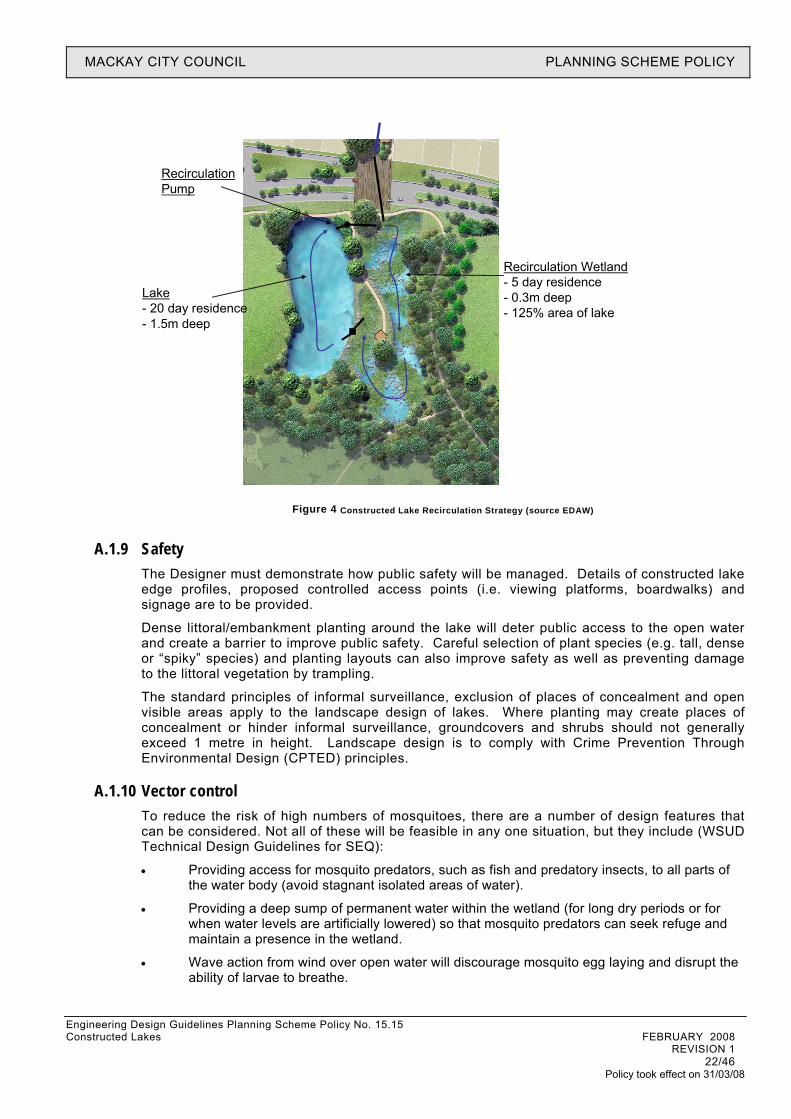
Where water quality monitoring of the constructed lake indicates degraded water quality or a high risk for algal bloom, a recirculation pump will be activated to pass lake water through a wetland system to limit the growth of algae (by creating a competitive environment) and reduce nutrient levels in the water column (refer Figure 4 for conceptual illustration). The wetland should be designed to ensure a permanent pool that extends over the majority of the wetland area. The pump rate and wetland system should be sized to provide the following:
• 20 day residence time in the constructed lake
• 5 day continuous residence time within the wetland (for continuous treatment of lake waters)
Attachment B provides the calculations required to establish the size of the recirculation. For conceptual design purposes, the general rule when creating a lake in Mackay is that the wetland recirculation area needs to be 1 to 1.25 times the lake surface area.
MACKAY CITY COUNCIL PLANNING SCHEME POLICY
Engineering Design Guidelines Planning Scheme Policy No. 15.15
Figure 4 Constructed Lake Recirculation Strategy (source EDAW)
Recirculation Wetland- 5 day residence- 0.3m deep- 125% area of lake
Lake- 20 day residence- 1.5m deep
Recirculation Pump
A.1.9 Safety The Designer must demonstrate how public safety will be managed. Details of constructed lake edge profiles, proposed controlled access points (i.e. viewing platforms, boardwalks) and signage are to be provided.
Dense littoral/embankment planting around the lake will deter public access to the open water and create a barrier to improve public safety. Careful selection of plant species (e.g. tall, dense or “spiky” species) and planting layouts can also improve safety as well as preventing damage to the littoral vegetation by trampling.
The standard principles of informal surveillance, exclusion of places of concealment and open visible areas apply to the landscape design of lakes. Where planting may create places of concealment or hinder informal surveillance, groundcovers and shrubs should not generally exceed 1 metre in height. Landscape design is to comply with Crime Prevention Through Environmental Design (CPTED) principles.
A.1.10 Vector control To reduce the risk of high numbers of mosquitoes, there are a number of design features that can be considered. Not all of these will be feasible in any one situation, but they include (WSUD Technical Design Guidelines for SEQ):
• Providing access for mosquito predators, such as fish and predatory insects, to all parts of the water body (avoid stagnant isolated areas of water).
• Providing a deep sump of permanent water within the wetland (for long dry periods or for when water levels are artificially lowered) so that mosquito predators can seek refuge and maintain a presence in the wetland.
• Wave action from wind over open water will discourage mosquito egg laying and disrupt the ability of larvae to breathe.
Constructed Lakes FEBRUARY 2008 REVISION 1 22/46
Policy took effect on 31/03/08
MACKAY CITY COUNCIL PLANNING SCHEME POLICY
Engineering Design Guidelines Planning Scheme Policy No. 15.15 Constructed Lakes FEBRUARY 2008 REVISION 1 23/46
Policy took effect on 31/03/08
• Providing sufficient gross pollutant control at the inlet such that human derived litter does not accumulate and provide breeding habitat.
• Providing ready access for field operators to monitor and treat mosquito larvae.
• Ensuring maintenance procedures do not result in wheel rut and other localised depressions that create isolated pools when water levels fall.
• Ensuring overflow channels don’t have depressions that will hold water after a storm event.
• Water weeds such as Water Hyacinth and Salvinia can provide a breeding medium for some mosquito species whose larvae attach to these plants under water. These weeds should be removed immediately if encountered.
Each case has to be considered on its own merits. It may be possible that a well established constructed lake will have no significant mosquito breeding associated with it; however, changes in climatic and vegetation conditions could change that situation rapidly. Maintaining awareness for mosquito problems and regular monitoring for mosquito activity should be considered as a component of the management of these sites. Effective and environmentally sound control products are available for control of mosquito larvae in these situations.
A.1.11 Bird population control
Large water bird populations can cause a wide range of problems in urban environments including:
• Noise generated by nesting colonies.
• Aesthetic and odour impacts of droppings in nesting/roosting and resting areas.
• Poor lake water quality due to nutrient loading from droppings.
• A disease reservoir for potential human pathogenic organisms such as Salmonella.
• Disturbance to humans because of foraging behaviour around recreational and picnic areas.
• Aircraft bird-strike risk.
• Reduction of local biodiversity through damage to native vegetation as a result of nesting and roosting activity (particularly by Ibis).
To avoid large water bird populations, particularly of nuisance species such as Ibis, the following design features should be considered:
• Densely vegetate lake edges with emergent macrophytes to a depth of 0.5m ( to inhibit access to shallow water for feeding).
• Island features in lakes should be avoided because they provide a secure environment for nuisance species such as Ibis, increase potential feeding and roosting habitat and can be hard to access and maintain.
• The inclusion of large, non-roosting trees (such as a range of Eucalyptus spp.) can reduce the attractiveness of lawn areas (for resting and feeding habitat) by reducing surveillance and comfort distances.
• Terrestrial vegetation immediately behind the littoral vegetation should not be species that would support a breeding or roosting colony of Ibis (e.g. some Melaleuca species).
• Actively discourage the feeding of water birds with appropriate signage and community education (consultation with Council required).
• Provide garbage bins with lids in picnic areas to prevent scavenging.

MACKAY CITY COUNCIL PLANNING SCHEME POLICY
Engineering Design Guidelines Planning Scheme Policy No. 15.15 Constructed Lakes FEBRUARY 2008 REVISION 1 24/46
Policy took effect on 31/03/08
Attachment B Constructed Lake Functional Design
Process

MACKAY CITY COUNCIL PLANNING SCHEME POLICY
B Constructed Lake Functional Design Process (Authored by Ecological Engineering)
B1 Introduction The following sections outline acceptable key design steps associated with the functional concept and detail design of constructed lakes in Mackay.
B2 Design Steps
B.2.1 STEP 1: ESTABLISH DESIGN INTENT The proponent must clearly describe the intended purpose of the proposed constructed lake. As stated earlier, Council will not accept stormwater quality improvement as an intended end use. Intended uses may include any or all of the following:
• Amenity. • Stormwater harvesting (storage and reuse of treated stormwater) - if the lake is to be used
for storage of treated stormwater for recycling the intended uses for the recycled water must also be stated (e.g. garden watering, toilet flushing).
• Flood management - lakes often form part of a flood retarding system and design requirements are generally associated with hydraulic structures for flow conveyance and flood attenuation. Flood design issues are not specifically covered in this document but it is expected appropriate hydraulic assessment is undertaken and presented in a Flood/Hydraulic Report (see STEP 13).
• Fill Requirements - if the lake is to provide for filling purposes within the adjacent development this must be stated and the volume of fill gained from the lake must be stated.
The design intent statement must also include the following:
• Location and configuration in relation to the development layout. • Location and configuration in relation to existing vegetation or receiving aquatic
environment. Council will not approve the creation of a constructed lake if it involves the removal of significant vegetation or the disturbance of a natural waterway (the categorisation of a natural waterway is at the discretion of Council). The lake is not to be created along the alignment of a natural waterway; it must be created off-line. The basis for this is to minimise the disturbance to the passage of aquatic fauna and fish along waterways. If an in-stream structure, such as a weir, is required to divert stream flows into an off-line pond or lake system then the proponent must demonstrate how the design of the in-stream structure accommodates passage for aquatic fauna (e.g. fish) and allows for stream base flows to bypass the lake.
• Landscape embellishments including pathways, boardwalks, viewing platforms, interpretative signs etc.
B.2.2 STEP 2: SITE, SOIL AND GROUND WATER EVALUATION There are a range of site and soil conditions which influence constructed lake design. To define the site’s capability to support a permanent waterbody, a ‘Site and Soil Evaluation’ must
Engineering Design Guidelines Planning Scheme Policy No. 15.15 Constructed Lakes FEBRUARY 2008 REVISION 1 25/46
Policy took effect on 31/03/08

MACKAY CITY COUNCIL PLANNING SCHEME POLICY
Engineering Design Guidelines Planning Scheme Policy No. 15.15 Constructed Lakes FEBRUARY 2008 REVISION 1 26/46
Policy took effect on 31/03/08
be undertaken in accordance with AS/NZS 1547:2000 Clause 4.1.3. The evaluation should provide the following:
• Soil type • Hydraulic conductivity (must be measured in accordance with AS/NZS 1547:2000
Appendix 4.1F) • Presence of soil salinity (where applicable), dispersivity and potential acid sulfate • Presence of rock shale • Slope of terrain (%) • Groundwater details (depth, quality and values). Where the in-situ soil type is found to be dispersive, appropriate control will be required. This may involve placing topsoil (or non-dispersive soil) throughout the base of the lake to control the potential release of dispersive soil to the water column.
In relation to groundwater, Council will not accept a pond or lake design that impacts on the local groundwater. The proponent must provide evidence to show that the constructed lake design does not have any negative interaction with local groundwater taking into consideration the likely seasonal fluctuations in the groundwater table. Basin lining, compaction of pond sides and base and potential for infiltration to groundwater may need to be considered where required.
Lakes proposed within areas that are mapped by Council as having Potential Acid Sulphate Soils (PASS) will need to have a detailed Acid Sulphate Soil Management Plan prepared and submitted to Council for approval.
B.2.3 STEP 3: DELINEATE CATCHMENT The catchment draining to the constructed lake dictates the sustainable maximum size of the lake and therefore must be identified and delineated on appropriate plans and mapping for Council review. Existing and proposed trunk drainage must also be identified along with likely percentage imperviousness.
B.2.4 STEP 4: PRE-TREATMENT DESIGN As outlined above, Council considers constructed lakes as receiving waterbodies and as such requires stormwater inflows to be pre-treated in accordance with Council’s Stormwater Quality Objectives (ref Stormwater Quality Management Plan for Mackay). The proponent must provide documented evidence to show the level of stormwater pre-treatment proposed is sufficient to comply with Council’s WQO’s (i.e. Site Based Stormwater Management Plan).
In all cases, MUSIC modelling is required to demonstrate the level of stormwater pre-treatment provided by the proposed stormwater treatment train. MUSIC modelling shall be undertaken in accordance with GCCC (2006) and BCC (2003).
B.2.5 STEP 5: CONFIRM NEED FOR PUMP RECIRCULATION & WETLAND (RESIDENCE TIME) As presented in the Residence Time (& Algal Growth) section above, the climatic conditions in Mackay mean lake residence times are above sustainable levels (greater than 20 days) regularly throughout any given year. Therefore, it is expected most lake applications within Mackay will require pump recirculation through a constructed wetland and this must be stated by the proponent.
In situations where the proposed lake is very small in relation to its catchment (i.e. where a lake area is <0.2% of the catchment area), there may be appropriate flows entering the constructed lake to ensure the 20%ile residence time (detention time) for the constructed lake should not exceed 20 days is achieved. To test this case the proponent must generate cumulative probability distribution curves of lake residence time through water balance modelling. Probability distribution curves must be generated for both the whole climate record (50 years minimum) and for the winter-spring periods only (June to November periods only for
MACKAY CITY COUNCIL PLANNING SCHEME POLICY
Engineering Design Guidelines Planning Scheme Policy No. 15.15 Constructed Lakes FEBRUARY 2008 REVISION 1 27/46
Policy took effect on 31/03/08
the 50 years minimum). For further guidance in relation to the generation of these curves please contact Council.
B.2.6 STEP 6: DEFINE MAXIMUM LAKE & WETLAND AREA (WATER LEVEL VARIATION) The proponent must provide to Council evidence of the ability of the catchment to provide sufficient water to maintain adequate water levels in the lake and associated recirculation wetland. If there is insufficient catchment to provide the inflows required to sustain lake levels, prolonged periods of low water levels could result in reduced aesthetic values and potential aquatic plant die-off. To assess the interaction between catchment hydrology (flows entering the lake) and lake water level, the proponent must undertake water balance modelling and assessment to consider the following:
• Seasonal rainfall and evaporation (pan) for Mackay - Minimum of 40 years simulation using relevant climate data. Where evaporation information is not available then the following can be adopted
• Catchment characteristics including area and percentage impervious. • Lake area and wetland area – As illustrated in Figure 4, constructed lake systems in
Mackay are to consist of an open water area (lake) and a recirculation wetland (see STEPS 10 & 11). The water balance assessment must consider evaporative losses from both these waterbodies.
The MUSIC modelling software can be used to establish daily stormwater flows into the lake system and a spreadsheet used to define lake interactions including overflows, evaporative losses, direct rainfall to the lake surface and resulting water level variation. Two scenarios must be modelled:
• Lake and Wetland (no recirc) - • Lake and Wetland (recirc)
The maximum constructed lake and wetland area is defined by the following objectives:
• Limiting the periodic (yearly) water level variation to 0.3-0.4 m below normal water level. This variation can be appropriately managed in terms of amenity by planting to the banks of the lake with a range of littoral to deep marsh aquatic plants that can tolerate this degree of water level variation.
• Limiting infrequent (1 in 5yrs or less frequent) water level variation to 0.5 m below normal water level. Long periods of significant drying have the potential to create difficult conditions for the aquatic plants, even plants that are suited to a level of drying. Additionally this level of variation will be readily noticed by visitors to the lake thus reducing the amenity of the system.
• Ensuring severe water level drawdown (i.e. > 0.5m below normal water level) does not occur more than once every 20 years (on average).
To assist in the conceptual design of lake systems in Mackay the design curve below has been established based on the process described above. Please refer to ‘Discussion of Water Level Variation Document’ for details. Water balance testing indicates that lakes in Mackay can sustain a water level with the recirculation through the wetland is not operating. However, lake water levels drop when the recirculation in activated due to the requirement to “fill” the wetland. The ‘Discussion of Water Level Variation Document’ quantifies this drop. Considering the recirculation is not meant to be operating permanently but rather only during times of very poor water quality (i.e. algal blooms) the issue of low water levels is not considered a major concern because they will be experienced irregularly and in times when other amenity issues have a higher priority (i.e. algal blooms).

MACKAY CITY COUNCIL PLANNING SCHEME POLICY
Engineering Design Guidelines Planning Scheme Policy No. 15.15 Constructed Lakes FEBRUARY 2008 REVISION 1 28/46
Policy took effect on 31/03/08
NOTE: This assessment approach described above is considered to be conservative because it does not account for groundwater interactions and urban water leakages to the lake which both act to preserve water level (i.e. add water to the lake).
B.2.7 STEP 7: SELECT FINAL LAKE AREA The final lake area must be selected considering the design intent (STEP 1), the site and soil characteristics (STEP 2) and its relationship with the development layout and receiving environment. The lake must allocate appropriate area for the recirculation wetland (see STEP 10) and the total lake and wetland area must not be greater than the maximum area defined in STEP 6.
B.2.8 STEP 8: CONFIRM LAKE DEPTH The depth of the lake must be within to 1.5m to 3m. This depth is sufficiently deep to reduce the presence of emergent vegetation and floating attached vegetation (e.g.lillies) that would detract from the desired open water aesthetic and is shallow enough to reduce the likelihood of thermal stratification.
Importantly the deeper the lake, the larger the lake volume and therefore the larger the recirculation wetland volume required to provide for appropriate recirculation (see STEP 9 and 10).
B.2.9 STEP 9: SIZE RECIRCULATION PUMP RATE The recirculation pump should be designed to ensure the lake volume is ‘flushed’ every twenty days (i.e. lake residence time of 20 days):
• Recirculation Pump Rate (m3/day) = Lake Volume (m3) / 20 (days)
or
• Recirculation Pump Rate (L/s) = Lake Volume (L) / 20 (days) / 24 (hours) / 3600 (s)
A preliminary estimate of lake volume can be calculated by simply multiplying the lake area by its depth (1.5m). Further refinement of the lake volume is recommended by accounting for edge batters (refer STEP 14) which can occur through preliminary earthworks modelling (ACAD/12D).
B.2.10 STEP 10: ESTABLISH RECIRCULATION WETLAND DEPTH & AREA In order limit the growth of algae (by creating a competitive environment) and reduce nutrient levels in the water column, recirculated lake waters are to be delivered via the recirculation pump (STEP 9) into a constructed wetland. The wetland should be designed to ensure a vegetated permanent pool that extends over the majority of the wetland area. This requires appropriate wetland depths (average 0.3m) to support a range of emergent macrophytes ranging from shallow marsh (0-0.2m), marsh (0.2-0.35m) and deep marsh (0.35-0.5m) species. The wetland volume needs to provide for 5 days of continuous treatment:
Wetland Area (m2) = 5 days X Recirculation Pump Rate (m3/day) / Ave Wetland Depth (0.3m)
Treated waters from the wetland must be discharged back into the lake at the opposite end of the abstraction point to avoid short-circuiting of treated flows through the lake.
B.2.11 STEP 11: ESTABLISH LAKE (& WETLAND) CONFIGURATION To optimise hydraulic efficiency, i.e. reduce short circuits and dead zones, it is desirable to adopt a high length to width ratio and to avoid zones of water stagnation. The ratio of length to width varies depending on the size of the system and the site characteristics while inlet and outlet conditions as well as the general shape of the pond can influence the presences and
MACKAY CITY COUNCIL PLANNING SCHEME POLICY
Engineering Design Guidelines Planning Scheme Policy No. 15.15
extent of water stagnation zones. To simplify the design and earthworks, smaller systems tend to have length to width ratios at the lower end of the range. This can often lead to poor hydrodynamic conditions.
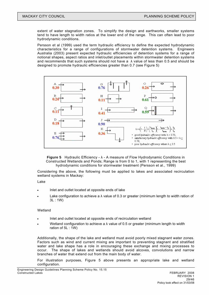
Persson et al (1999) used the term hydraulic efficiency to define the expected hydrodynamic characteristics for a range of configurations of stormwater detention systems. Engineers Australia (2003) present expected hydraulic efficiencies of detention systems for a range of notional shapes, aspect ratios and inlet/outlet placements within stormwater detention systems and recommends that such systems should not have a λ value of less than 0.5 and should be designed to promote hydraulic efficiencies greater than 0.7 (see Figure 5)
Figure 5 Hydraulic Efficiency - λ - A measure of Flow Hydrodynamic Conditions in Constructed Wetlands and Ponds; Range is from 0 to 1, with 1 representing the best
hydrodynamic conditions for stormwater treatment (Persson et al., 1999)
Considering the above, the following must be applied to lakes and associated recirculation wetland systems in Mackay:
Lake
• Inlet and outlet located at opposite ends of lake
• Lake configuration to achieve a λ value of 0.3 or greater (minimum length to width ration of 3L : 1W)
Wetland
• Inlet and outlet located at opposite ends of recirculation wetland • Wetland configuration to achieve a λ value of 0.5 or greater (minimum length to width
ration of 5L : 1W)
Additionally, the shape of the lake and wetland must avoid poorly mixed stagnant water zones. Factors such as wind and current mixing are important to preventing stagnant and stratified water and lake shape has a role in encouraging these exchange and mixing processes to occur. The shape of lakes and wetlands should avoid alcoves, convolutions and narrow branches of water that extend out from the main body of water.
For illustration purposes, Figure 5 above presents an appropriate lake and wetland configuration.
Constructed Lakes FEBRUARY 2008 REVISION 1 29/46
Policy took effect on 31/03/08

MACKAY CITY COUNCIL PLANNING SCHEME POLICY
Engineering Design Guidelines Planning Scheme Policy No. 15.15 Constructed Lakes FEBRUARY 2008 REVISION 1 30/46
Policy took effect on 31/03/08
B.2.12 STEP 12: FLOOD ROUTING DESIGN The proponent must provide to Council evidence that the proposed lake design will not have an adverse impact on flooding. The provision of a high-flow route through or around the lake is standard design practice to ensure flood flows can be safely conveyed either by the use of a spillway or ensuring that the embankment is designed to withstand overtopping. Where the lake system is to provide flood storage, this must be specifically stated in the Design Intent (STEP 1) and
Hydrologic and hydraulic modelling shall be undertaken in accordance with MCC requirements and QUDM requirements to demonstrate there will be no flooding impacts or define flood storage requirements. This issue requires specialised design input which is not discussed in this document.
B.2.13 STEP 13: DESIGN INLET & OUTLET STRUCTURES The movement of water through the lake is controlled by the inlet and outlet structures. As outlined in STEP 11, the inlet and outlet structures must be located at the far ends of the lake promote lake mixing and turnover and reduce short circuits and dead zones.
Inlet
Discharge of stormwater into the open waterbody of a lake may be via a vegetated inlet zone or direct input. In both cases it will be necessary to ensure that inflow energy is adequately dissipated so as not to cause localised scour in the vicinity of the pipe outfall. Design of stormwater pipe outfall structures are common hydraulic engineering practice and the designer is referred to relevant Council standards, QUDM and Road Drainage Design Manual (Main Roads, 2002) in this regard. Design calculations and design drawings must be provided to Council as part of the OWA.
Outlet
The outlet structure of a lake can be configured in many ways and is dependent on the specified operation of the system during periods of high inflows. Lakes may form part of a flood retarding basin in which case the outlet structure consist of two components, i.e. outlet pit and outlet culvert. The computation of the required outlet culvert is an essential element of the retarding basin design and will be based on flood routing computation as outlined in QUDM and ARR. The main function of the overflow pit is to maintain the desired permanent pool level and to provide a means of connecting the maintenance pipe (discussed below) to the outlet culvert. Design considerations of the outlet pit include the following:
• Ensure that the crest of the pit is set at the permanent pool level of the lake or pond
• Ensuring that the dimension of the pit provides discharge capacity that is greater than the discharge capacity of the outlet culvert or pipe
• Protection against clogging by debris
The dimension of an outlet pit must be determined in accordance with QUDM.
Maintenance Drain
The lake should be able to be drained or partially drained for maintenance with manual operation. A suitable design flow rate is one which can draw down the permanent pool within seven days although, depending on the volume of the lake, this may not be realistic.
The orifice discharge equation is considered suitable for sizing the maintenance drain (without blockage factor) on the assumption that the system will operate under inlet control.
If the local topography does not allow the draining of the lake via gravity, then this must be stated by the proponent and appropriate allowance for pumping provided (both through adequate access and maintenance costs).

MACKAY CITY COUNCIL PLANNING SCHEME POLICY
Engineering Design Guidelines Planning Scheme Policy No. 15.15
B.2.14 STEP 14: DESIGN LAKE EDGES & BATTERS Batter slopes on approaches and immediately under the water line have to be configured with consideration of public safety. Both hard and soft edge profiles can be applied to compliment the landscape of the surrounding area of a pond or lake. A soft edge profile will involve a gentle slope to the water edge and extending below the water line before the batter slope steepens into deeper areas.
The following general guidelines for soft edges are provided for vertical (V) to horizontal (H) side slope ratios:
• Maximum macrophyte planted safety shelf slopes between 1V:8H and 1V:15H for 2 to 3m from the edge of the water body.
• From the edge of the planted safety shelf, maximise deep water side slopes, preferably to 1V:1H, to prevent the spread of macrophytes and the growth of lilies (soil tests may be required to determine the steepest stable batters and if the slopes require stabilisation (e.g. rock));
Safety shelves should also be constructed to depth of no more than 0.5m.
Figure 6 shows a hard edge profile, using a vertical wall, and has an associated handrail for public safety. This edge profile uses rock to line the bottom of the pond to extend the ‘open water’ aesthetic to the edge of the lake. If fences are used consider styles suitable for parkland and urban/suburban contexts.
Both conceptual and detailed drawings submitted as part of the MCU/ROL and OW applications to Council are to clearly identify the application of soft and hard lake edge profiles with the detailed drawings providing detailed lake topography and cross sections.
Figure 6 Illustration of hard edge treatment for open waterbodies (GbLA, 2004)
B.2.15 STEP 15: VEGETATION SPECIFICATION Planting for constructed lakes may consist of up to three vegetation types:
• Macrophyte planting consisting of ephemeral marsh, shallow marsh, marsh and deep marsh (from 0.5 m below to 0.2 m above design water level)
• Embankment (littoral) vegetation (greater than 0.2 m above design water level)
• Terrestrial plants, including existing vegetation, adjacent to the embankment edge.
Constructed Lakes FEBRUARY 2008 REVISION 1 31/46
Policy took effect on 31/03/08
MACKAY CITY COUNCIL PLANNING SCHEME POLICY
Engineering Design Guidelines Planning Scheme Policy No. 15.15 Constructed Lakes FEBRUARY 2008 REVISION 1 32/46
Policy took effect on 31/03/08
The following sections provide general guidance in relation to the macrophyte planting and embankment planting. Consultation with Council in relation to plant species must occur and only native species will be accepted. Importantly a suitable layer of topsoil (200-300mm) must be placed along all lake edges which are to be planted and where the in-situ soil testing finds dispersive soils (STEP 1) along throughout the base of the lake. Topsoil must meet the requirements of AS4419 and be relatively low in nutrients and organic carbon (eg. ‘native plant’ topsoil mix).
Macrophyte Planting (from 1.0 m below to 0.2 m above design water level)
Guidance on selecting suitable plant species and cultivars that deliver the desired objectives for lakes must occur in consultation with Council. Macrophyte planting will predominantly consist of emergent macrophytes to provide a soft natural edge to the lake and provide a dense buffer between the open water in the lake and publicly accessible open space to discourage contact with the water.
Often the most effective way to meet those objectives with the macrophyte planting to suitable densities (6-10 plants per square metre) and within designed depth zones. When selecting suitable species it is important to also note the ability of some species to be highly self-sustaining. Macrophytes that distribute themselves by producing large quantities of seed material are great for colonizing and minimizing costs of replacements.
Submerged plants can also be established within the lake as they assist in maintaining good water quality, thus reducing risk of water quality related problems.
Embankment (Littoral) Vegetation (greater than 0.2 m above design water level) and Parkland Vegetation
Between the macrophyte planting and the top of the embankment, establishment of trees, shrubs and groundcovers can occur in consideration of the following:
• Selecting groundcovers, particularly for slopes greater than 1 in 3, with matting or rhizomataceous root systems to assist in binding the soil surface during the establishment phase. Example species include Imperata cylindrica (only if occurring naturally), Lomandra sp. and Cyndodacton sp.
• Preventing macrophyte plants from being shaded out by minimising tree densities at the water’s edge and choosing species such as Melaleuca that allow sunlight to penetrate the tree canopy.
• Locating vegetation to allow views of the lake and its surrounds whilst discouraging the public from accessing the water body.
Adjacent parkland vegetation may be of a similar species to the embankments littoral vegetation and layout to visually integrate the sedimentation basin with its surrounds. Alternatively, vegetation of contrasting species and/ or layout may be selected to highlight the water body as a feature within the landscape.
B.2.16 STEP 16: MONITORING PROGRAMME Ongoing monitoring is required to ensure the lake performs in accordance with the design intent and is sustainable over the long term. The monitoring programme will also guide corrective actions, adaptive management responses and maintenance requirements. A Lake Monitoring Plan must be documented and submitted to Council as part of the MCU/ROL and refined as part of the OW applications to Council. The monitoring programme must make allowance for the recommendations provided in the “Monitoring Requirements” section below.
B.2.17 STEP 17: MAINTENANCE PLAN All maintenance and operation issues should be identified and fully costed within a Maintenance Plan to ensure that Council and the developer understand roles, responsibilities

MACKAY CITY COUNCIL PLANNING SCHEME POLICY
Engineering Design Guidelines Planning Scheme Policy No. 15.15 Constructed Lakes FEBRUARY 2008 REVISION 1 33/46
Policy took effect on 31/03/08
and liabilities. The maintenance plan must be closely linked to the monitoring to ensure maintenance responses can be guided by monitoring results. It is anticipated a preliminary maintenance plan and associated costs will be provided to Council and approved as part of the Material Change of Use or Reconfiguring a Lot application with the details of the maintenance plan resolved during Operational Works. The Maintenance Plan must make allowance for the recommendations provided in the “Maintenance Requirements” section below.
Consideration must be given to ease of access to the proposed lake system for cleaning and maintenance purposes, in particular the inlet, outlet and pump recirculation structures. Consideration should also be given to the logistics of draining the proposed lake (refer Maintenance Drain discussion in STEP 13).
B3 LANDSCAPE INTEGRATION Lakes can play a significant role in creating a community landscapes and urban ecology. The proponent must refer to the relevant “Landscape Design Notes” provided in Chapter 4 Sediment Basins and Chapter 6 Constructed Wetlands of the WSUD Technical Design Guidelines for SEQ for guidance.
B4 MONITORING REQUIREMENTS A Lake Monitoring Plan must be documented and submitted to Council as part of the MCU/ROL and refined as part of the OW applications to Council. The following sub-sections provide a summary of Council’s requirements in relation to monitoring by defining a schedule, reporting and corrective actions.
Monitoring Schedule
Purpose: To provide an ongoing record of water quality in the lake, assess the ecological health of the lake and provide a basis for undertaking remedial and adaptive management activities where required.
Methodology: In-situ monitoring with multiprobe for some parameters and samples collected and analysed by laboratory for others (see below for details).
Frequency: Monthly.
Period: Ongoing.
Location: As required
Parameters (in-situ): pH, turbidity, DO, temperature and EC at 0.5m depth intervals from surface to bed of lake.
Parameters (samples for lab): Faecal coliforms, chlorophyll-a, TSS, TN, NH3, TP.
Target Values: Target values that are considered appropriate for the lake are listed in the table below.
Target Values for Lake Water Quality
Constituent Target Value or Range pH 6.5 to 8.5 DO > 80% saturation Chlorophyll-a < 10 ug/L Faecal coliforms < 1000 organisms/100mL
Where monitoring indicates chlorophyll-a or faecal coliform concentrations above the target values the corrective actions presented in the following sub-sections will be initiated.
Reporting
The water quality monitoring results are to be summarised in results sheets. Copies of the results sheets are to be kept on site and made available to Council local and state government

MACKAY CITY COUNCIL PLANNING SCHEME POLICY
Engineering Design Guidelines Planning Scheme Policy No. 15.15 Constructed Lakes FEBRUARY 2008 REVISION 1 34/46
Policy took effect on 31/03/08
officers upon request. Quarterly reports are to be submitted to Council and this should be done within one month of the completion of the last monitoring event in the quarter. These reports will incorporate the raw results, a summary of climatic data for the local area during the monitoring period, a results summary, and a discussion of whether there were any instances where the target values were not met. If there were any such instances, a discussion of the corrective actions that were implemented must be included.
Corrective Actions & Adaptive Management (Lake)
If there are instances where the water quality monitoring results do not meet the target values listed in Table 1, corrective actions are to be implemented as soon as possible. The only exception to the immediate implementation of corrective actions is if it can be demonstrated that the source of ‘pollution’ is not as a result of the development, or any activities associated with the development. Further investigations are also to be initiated if problems are reported by the Contractor, Council or EPA (i.e. odour, fish kills). Corrective actions are to include, as a minimum:
• Investigate the cause of the water quality problem and develop a strategy to address the problem and to ensure that the problem does not recur. This may require consultation with the designers of the stormwater treatment strategy and/or other environmental consultants.
• Where possible, minimise the propagation of the problem by preventing discharge from the water body where the incident has occurred. For example, if the incident is confined to the lake, take measures to prevent this water from discharging to the receiving environment (i.e. temporarily block outlet).
• Inspect all stormwater treatment elements in the catchment that feeds to the water body experiencing the water quality problems. Determine whether any of these elements require remedial maintenance.
• Other corrective actions that are deemed appropriate responses to the specific incident should also be implemented.
Corrective actions that respond to problems identified as part of the water quality monitoring may take the form of remedial maintenance activities.
Adaptive Management of Algal Bloom Risk
Algal/phytoplankton cell density is an important water quality parameter because it has both human and ecological health implications. The target value for chlorophyll-a listed in Table 1 is 10 ug/L. The adaptive management approach outlined in Figure 8 overleaf is to be implemented in the event that elevated chlorophyll-a levels (>10 ug/L) are recorded in the lake. This will primarily involve recirculation of lake waters through the adjacent constructed wetland. In the event of an algal bloom (i.e. phytoplankton cell density > 50,000 cells/mL), it will be necessary to formulate a rehabilitation plan for the lake.

MACKAY CITY COUNCIL PLANNING SCHEME POLICY
Figure 8 – Algal Bloom Management Strategy for Lake (source Ecological Engineering & NHMRC 2005)
Engineering Design Guidelines Planning Scheme Policy No. 15.15 FEBRUARY 2008 Constructed Lakes REVISION 1 35/46
Policy took effect on 31/03/08
MACKAY CITY COUNCIL PLANNING SCHEME POLICY
Engineering Design Guidelines Planning Scheme Policy No. 15.15 FEBRUARY 2008 Constructed Lakes REVISION 1 36/46
Policy took effect on 31/03/08

MACKAY CITY COUNCIL PLANNING SCHEME POLICY
Engineering Design Guidelines Planning Scheme Policy No. 15.15 FEBRUARY 2008 Constructed Lakes REVISION 1 37/46
Policy took effect on 31/03/08
Adaptive Management of Faecal Pollution
The target value for faecal coliforms listed in Table 1 is 1000 organisms/100mL. The following adaptive management approach should be implemented in the event that elevated faecal coliforms (>1000 organisms/100mL) are recorded in the lake.

MACKAY CITY COUNCIL PLANNING SCHEME POLICY
Engineering Design Guidelines Planning Scheme Policy No. 15.15 FEBRUARY 2008 Constructed Lakes REVISION 1 38/46
Policy took effect on 31/03/08
Figure 9 – Adaptive Management Strategy for Faecal Pollution of Lake (source
Ecological Engineering & ANZECC)
MACKAY CITY COUNCIL PLANNING SCHEME POLICY
Engineering Design Guidelines Planning Scheme Policy No. 15.15 FEBRUARY 2008 Constructed Lakes REVISION 1 39/46
Policy took effect on 31/03/08
B5 INSPECTION & MAINTENANCE REQUIREMENTS Constructed lake systems require ongoing inspection and maintenance to ensure they establish and operate in accordance with the design intent. Potential problems associated with WSUD infrastructure as a result of poor maintenance include:
• Decreased aesthetic amenity;
• Reduced functional performance;
• Public health and safety risks; and
• Decreased habitat diversity (dominance of exotic weeds).
Importantly, the most intensive period of maintenance is during the plant establishment period (initial one to two years) when weed removal and some replanting may be required. The most intensive period of maintenance is during plant establishment period (first two years) when weed removal and replanting may be required. It is also the time when large loads of sediments could impact on plant growth, particularly in developing catchments with poor building controls. Debris removal is an ongoing maintenance function. If not removed, debris can block inlets or outlets, and can be unsightly if in a visible location. Inspection and removal of debris should be done regularly.
Typical maintenance of constructed lake systems will involve:
• routine inspection of the lake to identify any damage to vegetation, scouring, litter and debris build up or excessive mosquitoes
• routine inspection of inlet and outlet points to identify any areas of scour, litter build up and blockages
• removal of litter and debris
• removal and management of invasive weeds
• repair to lake profile to prevent the formation of isolated pools
• regular watering of littoral vegetation during plant establishment
• water level control during plant establishment
• replacement of plants that have died (from any cause) with plants of equivalent size and species as detailed in the planting schedule
• vegetation pest monitoring and control.
Inspections are recommended following large storm events to check for scour and damage.
All maintenance activities must be specified in a maintenance plan (and associated maintenance inspection forms) to be developed as part of the design procedure (Step 16). Maintenance personnel and asset managers will use this plan to ensure the wetlands continue to function as designed. To ensure maintenance activities are appropriate for the lake over time, maintenance plans should be updated a minimum of every three years. The maintenance plans and forms must address the following:
• inspection frequency
• maintenance frequency
• data collection/ storage requirements (i.e. during inspections)
• detailed clean-out procedures (main element of the plans) including:

MACKAY CITY COUNCIL PLANNING SCHEME POLICY
Engineering Design Guidelines Planning Scheme Policy No. 15.15 FEBRUARY 2008 Constructed Lakes REVISION 1 40/46
Policy took effect on 31/03/08
- equipment needs
- maintenance techniques
- occupational health and safety
- public safety
- environmental management considerations
- disposal requirements (of material removed)
- access issues
- stakeholder notification requirements
- data collection requirements (if any)
• design details.
An approved maintenance plan is required prior to asset transfer to Council and communication with Council is required regarding these details. Importantly an estimate of ongoing costs for maintenance must be provided to Council as part of the MCU/RoL prior to approval of the lake to ensure Council understand the maintenance obligations following asset handover.
MACKAY CITY COUNCIL PLANNING SCHEME POLICY
Engineering Design Guidelines Planning Scheme Policy No. 15.11 FEBRUARY 2008 Constructed Lakes REVISION 1 41/46
Policy took effect on 31/03/08
Attachment C Water Level Variation
MACKAY CITY COUNCIL PLANNING SCHEME POLICY
Engineering Design Guidelines Planning Scheme Policy No. 15.15 FEBRUARY 2008 Constructed Lakes REVISION 1 42/46
Policy took effect on 31/03/08
C Water Level Variation (Authored by Ecological Engineering)
C.1.1 Objectives In response to water level risks the following objectives have been set for lakes in Mackay:
• Limit the periodic (yearly) water level variation to 0.3-0.4 m below normal water level. This variation can be appropriately managed in terms of amenity by planting to the banks of the lake with a range of littoral to deep marsh aquatic plants that can tolerate this degree of water level variation.
• Limit infrequent (1 in 5yrs or less frequent) water level variation to 0.5 m below normal water level. Long periods of significant drying have the potential to create difficult conditions for the aquatic plants, even plants that are suited to a level of drying. Additionally this level of variation will be readily noticed by visitors to the lake thus reducing the amenity of the system.
• Ensure severe water level drawdown (i.e. > 0.5m below normal water level) does not occur more than once every 20 years (on average).
Note that potable water is not to be used for ‘top up’ of lakes.
C.1.2 Water Level Variation Figure 1 (below) shows how the frequency of occurrence of water level drawdown changes with increasing lake area. The implications of these results with regard to the criteria presented above are:
• Water level drawdown of 0.3 – 0.4m does not occur more frequently than once a year (on average) for all lake sizes assessed.
• Water level drawdown of 0.4 – 0.5m does not occur more frequently than once every 5 years (on average) as long as the lake area is restricted to 1.5% of the contributing catchment area.
• Water level drawdown of greater than 0.5m does not occur more frequently than once every 20 years (on average) as long as the lake area is restricted to 1.9% of the contributing catchment area.
Therefore, to satisfy the criteria developed for lakes in Mackay, a lake area needs to be sized at 1.5% (2% maximum) of the contributing catchment area (or less).
NOTE: This assessment is seen to be conservative because it does not account for groundwater interactions and urban water leakages to the lake which both act to preserve water level (i.e. add water to the lake).
C.1.3 Water Level Variation With Recirculation The analysis is complicated by the fact that, in order to meet ecological objectives, every lake needs to be accompanied by a wetland sized at 1 to 1.25 times the lake area. When water quality monitoring of the lake indicates there is an algal bloom risk, waters

MACKAY CITY COUNCIL PLANNING SCHEME POLICY
Engineering Design Guidelines Planning Scheme Policy No. 15.15 FEBRUARY 2008 Constructed Lakes REVISION 1 43/46
Policy took effect on 31/03/08
will be recirculated through the wetland. The consequence being that when the recirculation system is active, the wetland is maintained at normal water level by the recirculation regime, so any reduction in the combined volume of the lake/wetland (i.e. due to evaporation) is reflected in drawdown of the lake water level.
Figure 2 (below) shows the frequency of occurrence of water level drawdown when the wetland recirculation system is activated. In this instance, it is not possible to meet the water level objectives outlined above. Water level drawdown of 0.3 – 0.4m generally occurs every 6 – 12 months, while more severe water level drawdown of greater than 0.4m occurs every 1 – 2 years.
Figure 3 (below) shows a time series of water level drawdown for a lake sized at 1.5% of the contributing catchment area (without recirculation). This represents the size of lake that is deemed appropriate for Mackay based on an analysis of the curves presented in Figure 1.
Figure 4 shows a time series of water level drawdown for a lake sized at 0.75% of the contributing catchment area, accompanied by a recirculation wetland of the same surface area. The combined surface area is the same as for the lake in Figure 3 (i.e. 1.5% of contributing catchment). The dramatic effect of wetland recirculation on the water level drawdown in the lake is evident.
C.1.4 Design Responses to Severe Water Level Drawdown Figure 5 shows a potential solution to the severe water level drawdown presented in Figure 4. In this instance, the lake is topped up with excess stormwater stored in an underground storage. The required size of the storage is equivalent to 0.5m multiplied by the surface area of the lake (i.e. one third of the lake volume) which represents a relatively large cost item.
Other potential design responses to the water level drawdown presented in Figure 4 (below) include:
• Partitioning the recirculation wetland. The recirculation wetland is sized to ensure adequate recirculation of the total lake volume. However, as the water level in the lake drops, the volume of water in the lake also decreases. As such, it is not necessary to use the entire wetland for recirculation. The benefit of partitioning the wetland is that there is less area available for evaporation.
• Creating part of the lake as a wetland edge. In order to preserve the macrophytes around the perimeter of the lake, it seems appropriate to create a wetland edge that can retain water via pumping from the lake. A low level bund would need to be created between the wetland edge and the lake open water to hold water in the wetland while the lake water level is low.
• Utilising ‘hard’ edges to the lake e.g. concrete walls. To mask the potentially large water level variation and creation open water and certain locations for amenity purposes, hard edges can be created.

MACKAY CITY COUNCIL PLANNING SCHEME POLICY
Engineering Design Guidelines Planning Scheme Policy No. 15.15 FEBRUARY 2008
Frequency of Drawdown of Lake Water Level (without recirculation through wetland)
0
5
10
15
20
25
30
0.0% 0.5% 1.0% 1.5% 2.0% 2.5% 3.0% 3.5% 4.0% 4.5% 5.0%
Lake Area as Percentage of Contributing Catchment Area (%)
Ave
rage
Fre
quen
cy o
f Occ
urre
nce
(yrs
)water level drawdown of 0.3m to 0.4mwater level drawdown of 0.4m to 0.5mwater level drawdown of > 0.5m
Figure 1 – Frequency of Drawdown of Lake Water Level (without wetland
recirculation)
Frequency of Drawdown of Lake Water Level (with recirculation through wetland)
0
5
10
15
20
25
30
0.0% 0.5% 1.0% 1.5% 2.0% 2.5% 3.0% 3.5% 4.0% 4.5% 5.0%
Lake Area as Percentage of Contributing Catchment Area (%)
Ave
rage
Fre
quen
cy o
f Occ
urre
nce
(yrs
)
water level drawdown of 0.3m to 0.4mwater level drawdown of 0.4m to 0.5mwater level drawdown of > 0.5m
Figure 2 – Frequency of Drawdown of Lake Water Level (with wetland
recirculation)
Constructed Lakes REVISION 1 44/46
Policy took effect on 31/03/08

MACKAY CITY COUNCIL PLANNING SCHEME POLICY
Engineering Design Guidelines Planning Scheme Policy No. 15.15 FEBRUARY 2008
Drawdown in Lake Water Level (without recirculation through wetland)(lake area sized at 1.50% of contributing catchment area)
-1.00
-0.95
-0.90
-0.85
-0.80
-0.75
-0.70
-0.65
-0.60
-0.55
-0.50
-0.45
-0.40
-0.35
-0.30
-0.25
-0.20
-0.15
-0.10
-0.05
0.00
0.05
1960 1965 1970 1975 1980 1985 1990 1995 2000Time
Wat
er L
evel
Dra
wdo
wn
(m)
Figure 3 – Time Series of Drawdown of Lake Water Level (without recirculation)
Drawdown in Lake Water Level (with recirculation through wetland)(lake area sized at 0.75% of contributing catchment area; recirculation wetland area sized at 0.75% of contributing catchment area)
-1.00
-0.95
-0.90
-0.85
-0.80
-0.75
-0.70
-0.65
-0.60
-0.55
-0.50
-0.45
-0.40
-0.35
-0.30
-0.25
-0.20
-0.15
-0.10
-0.05
0.00
0.05
1960 1965 1970 1975 1980 1985 1990 1995 2000Time
Wat
er L
evel
Dra
wdo
wn
(m)
Figure 4 – Time Series of Drawdown of Lake Water Level (with recirculation)
Constructed Lakes REVISION 1 45/46
Policy took effect on 31/03/08

MACKAY CITY COUNCIL PLANNING SCHEME POLICY
Engineering Design Guidelines Planning Scheme Policy No. 15.15 FEBRUARY 2008
Drawdown in Lake Water Level (with recirculation through wetland & top-up storage)(lake sized at 0.75% of catchment; recirculation wetland sized at 0.75% of catchment; top-up storage sized at 0.5m x area of lake)
-1.00
-0.95
-0.90
-0.85
-0.80
-0.75
-0.70
-0.65
-0.60
-0.55
-0.50
-0.45
-0.40
-0.35
-0.30
-0.25
-0.20
-0.15
-0.10
-0.05
0.00
0.05
1960 1965 1970 1975 1980 1985 1990 1995 2000Time
Wat
er L
evel
Dra
wdo
wn
(m)
Figure 5 – Time Series of Drawdown of Lake Water Level (with wetland
recirculation & top-up storage)
Constructed Lakes REVISION 1 46/46
Policy took effect on 31/03/08