engineering directorate structural engineering division · prc-6501 rev. f . process specification...
TRANSCRIPT

PRC-6501 Rev. F
Process Specification for Ultrasonic Inspection of Composites
Engineering Directorate
Structural Engineering Division
May 2014
National Aeronautics and Space Administration
Lyndon B. Johnson Space Center Houston, Texas
Verify current version before use Page 1of12

PRC-6501 Rev. F
Process Specification for Ultrasonic Inspection of Composites
s-s~ 't Revised by: Ajay Koshti, Date Materials and Processes Branch/ES4
- _,.Reviewed by: ~--:.-IL(~on~David M. Stanley: Date Materials and Processes
Branch/ES4~w -bs)
Approved by: Rachel Kamenetzlfy;Chief, Materials and Processes Branch/ES4
REVISIONS
VERSION DESCRIPTION DATE
Baseline Original version 5/27/97
A Modified Section 3.1 "Levels" to replace MIP's with
inspection points; modified Section 6.5 "Reference
Standards" to eliminate +/-4 dB requirement; clarified
report requirements for work performed at JSC
facilities in Section 6.13 "Inspection Report. "
8/28/98
B Modified the porosity acceptance criteria in Section 7.3
to account for part thickness and test frequency
variations.
8/11 /00
c Reviewed document per QMS requirements. Updated
division name, organization codes, and document
numbers.
5/21/03
Verify current version before use Page 2of12

PRC-6501 Rev. F
REVISIONS
VERSION DESCRIPTION DATE
D Revised applicable documents and inspection methods 01 /04/10
E Revised paragraph 9.0 for uniformity across al l NOE
PR Cs.
6/29/11
F Added NASA-STD-5009 to paragraph 4.0. Deleted
MIL-STD-2154 from paragraph 5.0 and added ASTM E
2375. Deleted the term "Material Data Sheet" from
paragraphs 6.4 and 6.12 for clarity.
Verify current version before use Page 3 of 12

PRC-6501 Rev. F
1.0 SCOPE
This document establishes the minimum requirements for ultrasonic inspection of laminated composites, bonded laminates, and adhesively bonded honeycomb composite structures.
2.0 APPLICABILITY
This specification shall be applicable whenever ultrasonic inspection is invoked per Section 3.0, "Usage".
3.0 USAGE
This specification shall be invoked by including an inspection note in the applicable drawing as exemplified in Figure 1.
ULTRASONICALLY INSPECT PER JSC PRC-6501, Level 1
Figure 1. Example of an ultrasonic inspection note for a composite part.
3.1 LEVELS
The "Level" designator governs the extent to which quality assurance provisions are applied and shall be specified in the inspection note on the basis of the following definitions:
a. Level 1 - Level 1 inspections are those generally applied to Class I or Class II hardware. The procedures for Level 1 inspections shall have inspection points for the calibration of the ultrasonic test equipment and for evaluation of flaw indications. Traceable records for all inspection points shall be maintained as a permanent quality record .
b. Level 2 - Level 2 inspections are those generally applied to Class Ill hardware or ground support equipment (GSE). There are no special process verification requirements for Level 2 inspections.
3.2 ACCEPTANCE CRITERIA
Unless otherwise stated on the drawing, the standard acceptance criteria in Section 7.0 shall be applicable. If alternate acceptance criteria are desired, then the criteria shall be added to the inspection note as exemplified in Figure 2. The
Verify current version before use Page 4 of 12

PRC-6501 Rev. F
acceptance criteria specified in the inspection note supersede the standard acceptance criteria in their entirety.
ULTRASONICALLY INSPECT PER JSC PRC-6501, Level 1, DELAMINATIONS, DISBONDS, AND POROSITY GREATER THAN 1 INCH DIAMETER ARE REJECTABLE
Figure 2. Example of an ultrasonic inspection note requiring modified acceptance criteria.
4.0 APPLICABLE DOCUMENTS
ASTM E 317, Practice for Evaluating the Performance Characteristics of Ultrasonic Pulse-Echo Testing Systems without the Use of Electronic Measurement Instruments
NAS 410, NAS Certification & Qualification of Nondestructive Test Personnel
NASA-STD-5009, Nondestructive Evaluation Requirements for FractureCritical Metallic Components
SNT-TC-1A, Personnel Qualification and Certification m Nondestructive Testing
5.0 REFERENCED DOCUMENTS
SOP-007.1, Preparation and Revision of Process Specifications (PRC's)
ASTM E 2375, Standard Practice for Ultrasonic Testing of Wrought Products
6.0 PROCESS REQUIREMENTS
6.1 WRITTEN PROCEDURE
All inspections shall be performed in accordance with a detailed written procedure. The procedure shall meet the requirements of this specification and include the following :
Verify current version before use Page 5 of 12

PRC-6501 Rev. F
a. Reference to this PRC by number and title.
b. Manufacturer and model numbers of all instrumentation.
c. Type, size, and frequency of the transducers used as well as a description of any wedges, shoes, bubblers, or squirters.
d . Description of any couplant additives.
e. Description of scanning equipment and method for determining scan speeds and indexes.
f. Scan plan.
g. Description of the calibration procedure and reference standards.
h. Discontinuity evaluation procedure.
i. Any other pertinent data.
For work performed at JSC facilities, written procedures shall consist of Detailed Process Instructions (DPls) selected for use from the DPl-6501-XX series of work instructions.
6.2 INSPECTION METHOD
Both pulse-echo and through-transmission C-scan inspection methods are acceptable. Contact pulse-echo A-scan inspection methods can be used to inspect those areas where C-scan inspection is impossible or impractical. In addition the reflector plate C-scan, phased array ultrasonic C-scan, and ultrasonic camera C-scan methods are acceptable.
6.3 EQUIPMENT
The equipment used shall be capable of performing inspections to the requirements of this specification. Transducer frequencies and sizes shall be selected to provide optimum detection of unacceptable flaws in the structure inspected . Electronic equipment, when used with the appropriate transducers, shall be capable of operating in the frequency range of at least 1 to 10 MHz. The horizontal and vertical linearity of the equipment shall be checked annually using the procedures in ASTM E 317.
Verify current version before use Page 6 of 12

PRC-6501 Rev. F
6.4 COUPLANT
When water is used as a couplant, deionized water shall be used for Level 1 inspections. The water shall be free of air bubbles and other foreign matter which could interfere with the inspection. Corrosion inhibitors and wetting agents may be added, if necessary, to inhibit corrosion and prevent the formation of bubbles. However, any such additives must be approved by the responsible design authority.
Use of couplants other than deionized water for contact inspection of rough surfaces shall be approved by the responsible design authority. Parts subject to subsequent bonding operations shall be cleaned after inspection in accordance with approved cleaning procedures to ensure removal of all residual couplant.
6.5 REFERENCE STANDARDS
Reference standards with a physical configuration and acoustic properties similar to the part under test shall be used to establish the ultrasonic test parameters. The thickness of the reference standard shall be within 10 percent or 2 plies, whichever is greater, of the thickness of the part. Laminated composite reference standards shall have a porosity content of less than 0.2 percent by volume as verified by cross sectioning and optical analysis of a separate cocured test coupon or a sacrificial area of the actual standard . Attenuation shall not vary more than ± 2 dB across the reference standard.
The reference standard shall contain reference flaws representative of the types of defect which must be detected. Reference flaws used to establish the ultrasonic test parameters shall be equal to or smaller than the smallest unacceptable defect.
6.6 CALIBRATION
In addition to annual linearity checks, the inspection system shall be calibrated against the appropriate reference standard at the beginning and end of each inspection shift and every four hours in between. The system shall also be calibrated after any power interruption or system shutdown and before scanning any part where changes in part thickness of more than 10 percent have occurred . A C-scan of the reference standard clearly showing the relevant reference flaws shall be produced as part of the cal ibration procedure. All of the calibration C-scans shall be maintained as part of the inspection record .
Verify current version before use Page 7 of 12
PRC-6501 Rev. F
6.7 SURFACE PREPARATION
The surface of the laminate or honeycomb structure under test shall be free of any dirt, oil, or grease which may interfere with the inspection. Honeycomb structures with exposed core or facesheet penetrations shall be sealed prior to inspection to prevent water from entering the structure. All sealing materials added for inspection shall be removed from parts immediately after inspection.
6.8 SCANNING SPEED AND INDEXING INCREMENT
The scanning speed and indexing increment shall not exceed the maximum values which provide for detection of all relevant flaws in the reference standards used to set up the test.
6.9 COVERAGE
Unless otherwise specified by the responsible design authority, all parts shall be 100 percent inspected.
6.10 LOCATION MARKERS
If a part must be inspected in a series of two or more separate scans, then location markers, such as self adhesive lead tape, shall be placed on the surface of the part. The location markers shall be placed to aid in verifying that individual scans cover all of the intended inspection area and to aid in assembling separate scans into a single mosaic. The size of the markers shall be less than the smallest unacceptable flaw in order to avoid masking unacceptable defects.
6.11 FLAW EVALUATION
Defect indications shall be verified with manual A-scan techniques. Verified defects larger than allowable shall be labeled with the appropriate defect type, i.e., delamination, disbond, or porosity, on the c-scan recording and their location shall be marked on the surface of the part. In addition to the defect type, the estimated depth of delaminations shall be noted on the C-scan.
6.12 POST INSPECTION CLEANING
Parts shall be thoroughly cleaned and dried immediately following inspection in accordance with approved cleaning procedures.
6.13 INSPECTION REPORT
An inspection report shall be prepared for each part or group of parts. The report shall indicate compliance with this specification , reference the appropriate written procedure or DPI, and include the name and equivalent NOT Level of the
Verify current version before use Page 8 of 12

PRC-6501 Rev. F
personnel performing the inspection. The report shall identify each part by part number and serial number and indicate whether each part was accepted or rejected . The flaws in all rejected parts shall be noted and a hard copy of the Cscan showing the defective areas shall be attached to the report along with the relevant calibration C-scans. For work performed at JSC facilities, the inspection report shall consist of the completed JSC Form 1262, "Manufacturing Process Record" and , if applicable, a JSC Form 2176, "Discrepancy Report/Material Review Record". Inspection reports shall be retained as a permanent quality record and a copy provided to the responsible design authority.
7.0 STANDARD ACCEPTANCE CRITERIA
7.1 DELAMINATIONS, VOIDS, FOREIGN MATERIAL, AND LAMINATE-TOLAMINATE DISBONDS
Any single delamination, void, foreign material inclusion, or laminate-to-laminate disband with a length of 0.25 in. or greater shall be rejected . Any single delamination, void, foreign material inclusion, or laminate-to-laminate disband with an area of 0.049 in.2 or greater shall be rejected. The length and area requirements are separate requirements cind must be evaluated individually. Indications meeting either requirement shall be rejected.
Multiple delaminations, voids, foreign material inclusions, or laminate-to-laminate disbands with individual lengths less than 0.25 in. and areas less than 0.049 in.2
but separated by less than 1 inch shall be rejected.
7.2 LAMINATE-TO-CORE DISBONDS
Any single laminate-to-core disband with a length of 1 in. or greater shall be rejected. Any single laminate-to-core disband with an area of 0.785 in.2 or greater shall be rejected. The length and area requirements are separate requirements and must be evaluated individually. Indications meeting either requirement shall be rejected.
Multiple laminate-to-core disbands with individual lengths less than 1 in. and areas less than 0.785 in.2 but separated by less than 6 in. shall be rejected.
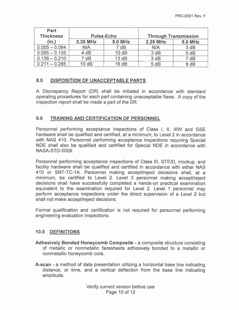
7.3 POROSITY
Any area of porosity with a length of 0.5 in . or greater or an area of 0.196 in.2 or greater and producing a signal drop relative to the appropriate reference standard equal to or greater than the dB value given in the following table shall be rejected.
Verify current version before use Page 9 of 12
PRC-6501 Rev. F
Part Thickness Pulse-Echo Through Transmission
(in.) 2.25 MHz 5.0 MHz 2.25 MHz 5.0 MHz 0.005 - 0.064 N/A 7 dB N/A 3 dB 0.065 - 0.135 4 dB 10 dB 3 dB 5 dB 0.136-0.210 7 dB 13 dB 3 dB 7 dB 0.211 - 0.285 10 dB 16 dB 5 dB 8 dB
8.0 DISPOSITION OF UNACCEPTABLE PARTS
A Discrepancy Report (DR) shall be initiated in accordance with standard operating procedures for each part containing unacceptable flaws. A copy of the inspection report shall be made a part of the DR.
9.0 TRAINING AND CERTIFICATION OF PERSONNEL
Personnel performing acceptance inspections of Class I, 11, ll lW and GSE hardware shall be qualified and certified , at a minimum, to Level 2 in accordance with NAS 410. Personnel performing acceptance inspections requiring Special NOE shall also be qualified and certified for Special NOE in accordance with NASA-STD-5009.
Personnel performing acceptance inspections of Class Ill , STE/D, mockup, and facility hardware shall be qualified and certified in accordance with either NAS 410 or SNT-TC-1A. Personnel making accept/reject decisions shall, at a min imum, be certified to Level 2. Level 3 personnel making accept/reject decisions shall have successfu lly completed a hands-on practical examination equivalent to the examination required for Level 2. Level 1 personnel may perform acceptance inspections under the direct supervision of a Level 2 but shall not make accept/reject decisions.
Formal qualification and certification is not required for personnel performing engineering evaluation inspections.
10.0 DEFINITIONS
Adhesively Bonded Honeycomb Composite - a composite structure consisting of metallic or nonmetallic facesheets adhesively bonded to a metallic or nonmetallic honeycomb core.
A-scan - a method of data presentation utilizing a horizontal base line indicating distance, or t ime, and a vertical deflection from the base line indicating amplitude.
Verify current version before use Page 10 of 12

PRC-6501 Rev. F
Class I Hardware - hardware acceptable for flight use.
Class II Hardware - hardware acceptable for use in ground test or training in a hazardous environment.
Class Ill Hardware - hardware acceptable for nonhazardous training or display purposes. This hardware is uncontrolled.
Contact Testing - a technique in which the search unit makes contact directly with the test piece through a thin layer of couplant.
Couplant - a substance used between the search unit and test surface to permit or improve transmission of ultrasonic energy.
C-scan - an ultrasonic data presentation which provides a plan view of the test object and discontinuities therein.
Delamination - a separation of laminated composite plies from each other.
Disbond - a separation at the adhesive layer of a laminate-to-laminate or laminate-to-core bond.
Foreign Material - any object contained within the laminated composite, bonded laminate or adhesively bonded honeycomb composite that is not specified on the engineering drawing.
Ground Support Equipment (GSE) - equipment acceptable for the control , handling, and testing of Class I and Class II hardware
Laminated Composite - a composite material made up of several bonded layers or plies each consisting of unidirectional or woven reinforcement fibers in a polymer matrix.
Porosity - small gas pores or air pockets within the matrix and/or bondline of a laminated composite or bonded panel.
Pulse-Echo Method - an inspection method in which the ultrasonic pulse is emitted and received by a single transducer. The presence and position of a flaw are indicated by the amplitude and time-of-flight of the ultrasonic energy reflected from the flaw.
Through Transmission Method - an inspection method in which the ultrasonic pulse is emitted by one transducer and received by another at the opposite surface of the material examined. The presence of a flaw is indicated by a decrease in the amplitude of the transmitted ultrasonic energy.
Verify current version before use Page 11 of 12
PRC-6501 Rev. F
Void - a relatively large localized gas pore or air pocket within the matrix and/or bondline of a laminated composite or bonded panel.
Verify current version before use Page 12 of 12