engineering fabric architecture - tensinet · engineering fabric architecture ... fabric structures...
TRANSCRIPT

ENGINEERINGFABRIC ARCHITECTURE
Chapter 2
Brian Forster, Marijke Mollaert

ENGINEERING FABRIC ARCHITECTURE
I 26 I
2.1 Introduction
Fabric structures provide widespan enclosures of great spatial interest and variety, requireminimal supporting elements of “hard” structure and provide very good overall levels of nat-ural daylight. The purpose of this chapter is to outline the nature and characteristics of thisstructural type and to describe the primary issues that designers deal with and makedecisions about.
From an engineering point of view fabric structures are thin membranes of constant thick-ness which by virtue of their surface shape and inherent large deflection behaviour are ableto support the imposed loads required by Building Codes. They are modestly prestressed toenhance their stiffness.
Whilst “tents” have a long history the origins of our contemporary fabric structure technol-ogy are to be found in the nineteenth century. For instance the mechanical spinning of yarnand weaving of cloth enabled large portable tents to be created for the travelling circusesthat abounded in the latter part of that century. Tents such as the “Chapiteau” (Figure 2.1)were up to 50m in diameter and made from machine woven linen or hemp canvas1. The“Chapiteau” was supported near its centre by four King poles situated around the circusring. The canvas hangs from these to frequent perimeter poles that are stayed by ropesanchored into the ground.Between the perimeter andthe King poles there is a fur-ther ring of Queen poles setat 60° to the ground, theirfunction being to lightly pre-tension the cloth, so as todiminish surface movementand flapping.
Whilst these were travelling structures, and therefore protected from exposure to the excess-es of climatic loading, their design embodies two of the primary features of the modern fab-ric structure – a deformable surface shape and pretension.
For the Pan-Russian Exhibition of 1896 the eminent Russian engineer V. G. Suchov designedfour exhibition halls of large clear span.2 The roof construction was intriguing in that Suchovemployed flexible 2-way networks of thin strip steel which in turn were clad in thin over-lapping steel tiles. The system as a whole formed an unprestressed “warped” surface hang-ing in tension under its own weight. In effect it obtained its stiffness, stability and load car-rying capacity from its surface shape, in conjunction with its self-weight.
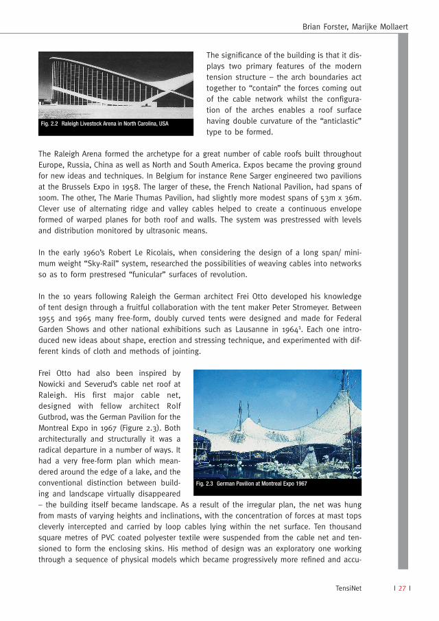
After a 50 year interval long span “saddle” shaped roofs started to be built commencingwith the Raleigh Livestock Arena in North Carolina, USA, designed by engineer Fred Severudand architect Matthew Nowicki and completed in 1952 (Figure 2.2). In essence the roof con-sists of a 2 – way network of cables spanning 95m between a pair of arches inclined awayfrom one another at 20° to the horizontal.
European Design Guide for Tensile Surface Structures
Fig. 2.1 Circus tent ‘Chapiteau’
I 27 I
The significance of the building is that it dis-plays two primary features of the moderntension structure – the arch boundaries acttogether to “contain” the forces coming outof the cable network whilst the configura-tion of the arches enables a roof surfacehaving double curvature of the “anticlastic”type to be formed.
The Raleigh Arena formed the archetype for a great number of cable roofs built throughoutEurope, Russia, China as well as North and South America. Expos became the proving groundfor new ideas and techniques. In Belgium for instance Rene Sarger engineered two pavilionsat the Brussels Expo in 1958. The larger of these, the French National Pavilion, had spans of100m. The other, The Marie Thumas Pavilion, had slightly more modest spans of 53m x 36m.Clever use of alternating ridge and valley cables helped to create a continuous envelopeformed of warped planes for both roof and walls. The system was prestressed with levelsand distribution monitored by ultrasonic means.
In the early 1960’s Robert Le Ricolais, when considering the design of a long span/ mini-mum weight “Sky-Rail” system, researched the possibilities of weaving cables into networksso as to form prestresed “funicular” surfaces of revolution.
In the 10 years following Raleigh the German architect Frei Otto developed his knowledgeof tent design through a fruitful collaboration with the tent maker Peter Stromeyer. Between1955 and 1965 many free-form, doubly curved tents were designed and made for FederalGarden Shows and other national exhibitions such as Lausanne in 19641. Each one intro-duced new ideas about shape, erection and stressing technique, and experimented with dif-ferent kinds of cloth and methods of jointing.
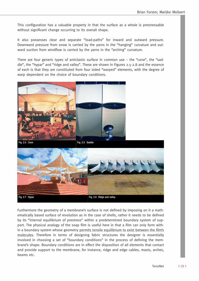
Frei Otto had also been inspired byNowicki and Severud’s cable net roof atRaleigh. His first major cable net,designed with fellow architect RolfGutbrod, was the German Pavilion for theMontreal Expo in 1967 (Figure 2.3). Botharchitecturally and structurally it was aradical departure in a number of ways. Ithad a very free-form plan which mean-dered around the edge of a lake, and theconventional distinction between build-ing and landscape virtually disappeared– the building itself became landscape. As a result of the irregular plan, the net was hungfrom masts of varying heights and inclinations, with the concentration of forces at mast topscleverly intercepted and carried by loop cables lying within the net surface. Ten thousandsquare metres of PVC coated polyester textile were suspended from the cable net and ten-sioned to form the enclosing skins. His method of design was an exploratory one workingthrough a sequence of physical models which became progressively more refined and accu-
Brian Forster, Marijke Mollaert
TensiNet
Fig. 2.2 Raleigh Livestock Arena in North Carolina, USA
Fig. 2.3 German Pavilion at Montreal Expo 1967

ENGINEERING FABRIC ARCHITECTURE
I 28 I
rate. As the behaviour of surface structures is largely conditioned by their geometry, thisapproach enabled him to combine his architectural ambitions with a structural logic as wellas a method of building. The process required painstaking care and time to build the finalmodels accurately enough for them to be measured for the purpose of structural analysis andconstruction drawings. The engineering design of the Pavilion was led by the office ofLeonhardt and Andra, who continued on with Günter Behnisch and Frei Otto to realise theastonishing cable net roofs for the 1972 Olympic Games in Munich. This project, because ofits scale and importance, marked a shift away from physical model testing to computer meth-ods for the justification of structural behaviour and capacity. Inevitably, non-linear engineer-ing software has embraced the choice and optimisation of surface geometry and the conver-sion of this into cutting patterns and dimensions for fabrication.
A more extended historical discussion is to be found in 3.
The materials commonly used in fabric structures consist of a woven textile encapsulated ina polymeric coating. There are for instance different constructions of weave, different weav-ing techniques which can include control on yarn straightness and tension which affect thestrain behaviour of the finished product. Such factors need to be understood and accom-modated in the engineering design and specification processes for each project. Chapter 8refers to numerical modelling techniques and Chapter 9 describes the formulation of thecommonly used materials and their characteristics.
2.2 Form and Behaviour of Fabric Structures
The form and physical behaviour of fabric structures are very different to those of conven-tionally stiff “linear-elastic” framed structures used in most buildings.
Designers of fabric structures concern themselves with three primary structural factors– choice of surface shape, levels of prestress and surface deformability.
Consideration has also to be made regarding the internal climate of spaces enclosed by textilemembranes as well as the choice of the particular type and grade of the membrane to be used.
2.2.1 SURFACE SHAPE
Most contemporary fabric structures haveas their basis an “anticlastic” surfacegeometry. This is one in which a set of“arching” tensile elements act in oppo-sition to a similar set of “hanging”elements (see Figure 2.4). Physically thetwo groups of elements represent thetwo directions of the textile yarns (warpand weft) within the membrane.
European Design Guide for Tensile Surface Structures
Fig. 2.4 Anti-clastic surface
I 29 I
This configuration has a valuable property in that the surface as a whole is prestressablewithout significant change occurring to its overall shape.
It also possesses clear and separate “load-paths” for inward and outward pressure.Downward pressure from snow is carried by the yarns in the “hanging” curvature and out-ward suction from windflow is carried by the yarns in the “arching” curvature.
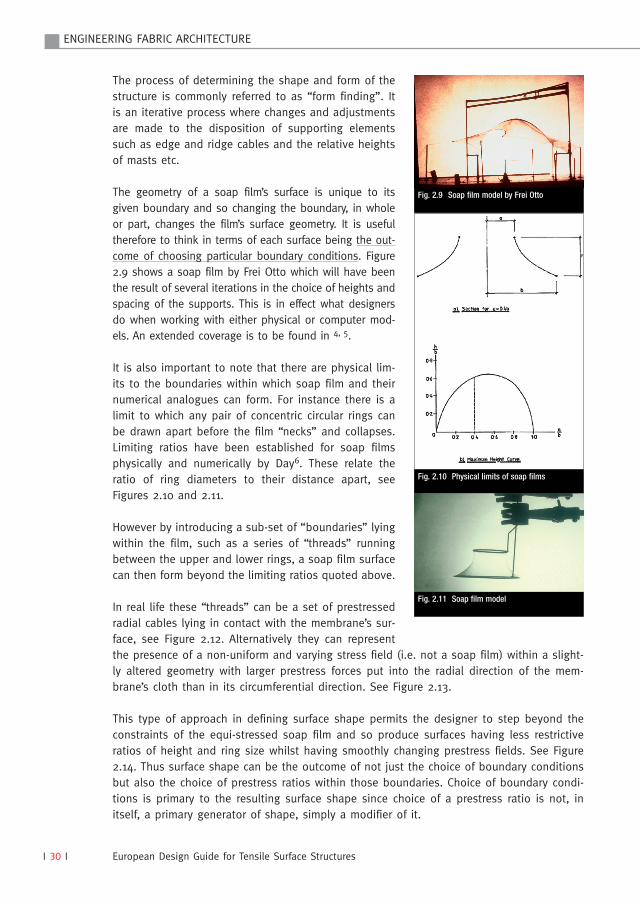
There are four generic types of anticlastic surface in common use – the “cone”, the “sad-dle”, the “hypar” and “ridge and valley”. These are shown in Figures 2.5-2.8 and the essenceof each is that they are constituted from four sided “warped” elements, with the degree ofwarp dependent on the choice of boundary conditions.
Furthermore the geometry of a membrane’s surface is not defined by imposing on it a math-ematically based surface of revolution as in the case of shells, rather it needs to be definedby its “internal equilibrium of prestress” within a predetermined boundary system of sup-port. The physical analogy of the soap film is useful here in that a film can only form with-in a boundary system whose geometry permits tensile equilibrium to exist between the film’smolecules. Therefore in terms of designing fabric structures the designer is essentiallyinvolved in choosing a set of “boundary conditions” in the process of defining the mem-brane’s shape. Boundary conditions are in effect the disposition of all elements that contactand provide support to the membrane, for instance, ridge and edge cables, masts, arches,beams etc.
Brian Forster, Marijke Mollaert
TensiNet
Fig. 2.5 Cone Fig. 2.5 Saddle
Fig. 2.7 Hypar Fig. 2.8 Ridge and valley
ENGINEERING FABRIC ARCHITECTURE
I 30 I
The process of determining the shape and form of thestructure is commonly referred to as “form finding”. Itis an iterative process where changes and adjustmentsare made to the disposition of supporting elementssuch as edge and ridge cables and the relative heightsof masts etc.
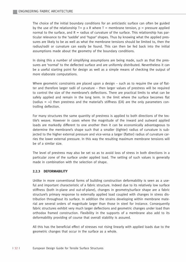
The geometry of a soap film’s surface is unique to itsgiven boundary and so changing the boundary, in wholeor part, changes the film’s surface geometry. It is usefultherefore to think in terms of each surface being the out-come of choosing particular boundary conditions. Figure2.9 shows a soap film by Frei Otto which will have beenthe result of several iterations in the choice of heights andspacing of the supports. This is in effect what designersdo when working with either physical or computer mod-els. An extended coverage is to be found in 4, 5.
It is also important to note that there are physical lim-its to the boundaries within which soap film and theirnumerical analogues can form. For instance there is alimit to which any pair of concentric circular rings canbe drawn apart before the film “necks” and collapses.Limiting ratios have been established for soap filmsphysically and numerically by Day6. These relate theratio of ring diameters to their distance apart, seeFigures 2.10 and 2.11.
However by introducing a sub-set of “boundaries” lyingwithin the film, such as a series of “threads” runningbetween the upper and lower rings, a soap film surfacecan then form beyond the limiting ratios quoted above.
In real life these “threads” can be a set of prestressedradial cables lying in contact with the membrane’s sur-face, see Figure 2.12. Alternatively they can representthe presence of a non-uniform and varying stress field (i.e. not a soap film) within a slight-ly altered geometry with larger prestress forces put into the radial direction of the mem-brane’s cloth than in its circumferential direction. See Figure 2.13.
This type of approach in defining surface shape permits the designer to step beyond theconstraints of the equi-stressed soap film and so produce surfaces having less restrictiveratios of height and ring size whilst having smoothly changing prestress fields. See Figure2.14. Thus surface shape can be the outcome of not just the choice of boundary conditionsbut also the choice of prestress ratios within those boundaries. Choice of boundary condi-tions is primary to the resulting surface shape since choice of a prestress ratio is not, initself, a primary generator of shape, simply a modifier of it.
European Design Guide for Tensile Surface Structures
Fig. 2.9 Soap film model by Frei Otto
Fig. 2.10 Physical limits of soap films
Fig. 2.11 Soap film model

I 31 I
The shapes that are possible for fabric structures aren’tsimply limited to the 4 generic shapes illustrated inFigures 2.5-2.8. Indeed hybrid versions and combina-tions thereof increase the choice of forms considerablyas can be seen in examples illustrated in Chapter 3.
Where very large areas have to be covered but with con-trol on the internal height to be maintained then mod-ular arrangements can be employed. The Haj PilgrimTerminal at Jeddah Airport in Saudi Arabia (Figure 2.5) isone such example in which 45.75m x 45.75m squarebased conical units cover a total area of 440,000m2 9.
The physical and numerical methods commonly usedfor “form finding” are described in Chapter 8.
2.2.2 PRESTRESS
Prestress contributes significantly to a membrane’sstiffness due to its opposing curvature componentsinteracting to constrain what would otherwise besevere deformations typical of flat or singly curved sur-faces. For example in Figure 2.15 the deformation of the“hanging” curvature due to loading in zone A is con-strained by the “arching” tensions in zone B. Actual val-ues of prestress used in practice generally represent asmall proportion of a membrane’s ultimate strength.
The chosen level of prestress will normally be a compro-mise – low enough to reduce the work done during instal-lation – whilst sufficiently high to maintain a sufficient pre-stress after losses due to ‘creep’ of the membrane materi-al over time. Some typical values of prestress used in prac-tice are given in Chapter 7 – Design Loading Conditions.
Brian Forster, Marijke Mollaert
TensiNet
Fig. 2.12 Radial cables lying in contact withmembrane’s surface
Fig. 2.13 Non-uniform prestress field
Fig. 2.14 Smoothly changing prestressfields
Fig. 2.15 Zone A constrained by arching tensions in zone B
ENGINEERING FABRIC ARCHITECTURE
I 32 I
The choice of the initial boundary conditions for an anticlastic surface can often be guidedby the use of the relationship T= p x R where T = membrane tension, p = pressure appliednormal to the surface, and R = radius of curvature of the surface. This relationship has par-ticular relevance to the ‘saddle’ and ‘hypar’ shapes. Thus by knowing what the applied pres-sures are likely to be as well as what the membrane tensions should be limited to, then theradius/radii or curvature can easily be found. This can then be fed back into the initialassumptions made about the geometry of the boundary conditions.
In doing this a number of simplifying assumptions are being made, such as that the pres-sures are ‘normal’ to the deflected surface and are uniformly distributed. Nevertheless it canbe a useful starting point for design as well as a simple means of checking the output ofmore elaborate computations.
Where geometric constraints are placed upon a design – such as to require the use of flat-ter and therefore larger radii of curvature – then larger values of prestress will be requiredto control the size of the membrane’s deflections. There are practical limits to what can besafely applied and remain in the long term. In the limit where the surface becomes flat(radius = ∞) then prestress and the material’s stiffness (EA) are the only parameters con-trolling deflection.
For many structures the same quantity of prestress is applied to both directions of the tex-tile’s weave. However in cases where the magnitude of the inward and outward appliedloads are markedly different to one another then it can be economically advantageous todetermine the membrane’s shape such that a smaller (tighter) radius of curvature is sub-jected to the higher external pressure and vice-versa a larger (flatter) radius of curvature car-ries the lower external pressure. In this way the resulting maximum membrane tensions willbe of a similar size.
The level of prestress may also be set so as to avoid loss of stress in both directions in aparticular zone of the surface under applied load. The setting of such values is generallymade in combination with the selection of shape.
2.2.3 DEFORMABILITY
Unlike in more conventional forms of building construction deformability is seen as a use-ful and important characteristic of a fabric structure. Indeed due to its relatively low surfacestiffness (both in-plane and out-of-plane), changes in geometry/surface shape are a fabricstructure’s primary response to externally applied load coupled with changes in stress dis-tribution throughout its surface. In addition the strains developing within membrane mate-rial are several orders of magnitude larger than those in steel for instance. Consequentlyfabric structures exhibit very much larger deflections and geometric changes under load thanorthodox framed construction. Flexibility in the supports of a membrane also add to itsdeformability providing of course that overall stability is assured.
All this has the beneficial effect of stresses not rising linearly with applied loads due to thegeometric changes that occur in the surface as a whole.
European Design Guide for Tensile Surface Structures

I 33 I
For instance wind flowing around a conical membrane causes a “pin-ended” mast to leaninto the wind allowing changes to surface curvature on the windward face to attenuate therise in membrane stresses in that zone, but also with membrane curvatures on the leewardside acting to stabilise the mast.
Heavy localised loading such as wind pressure on eaves and ridges is in effect supportedby a much larger area than simply the contact area of the pressure due to changes in sur-face geometry within the membrane.
Encouraging deformation of the membrane’s surface is beneficial provided that the deformedsurface under load remains with positive inclinations throughout. The inherent danger ofshallow gradients is that an accumulation of snow/ice can cause a depression into whichmeltwater and rain can collect (“ponding”) with the surface geometry having changed from“anticlastic” to “synclastic” (Figure 2.16). This in turn can increase the depth of the depres-sion allowing more water to pond and hence creating a larger depression and so on. It mayremain as water or convert to ice according to weather conditions. The effect however is forsnow loads to progressively increase far beyond those applicable to a more rigid structure7.The objective must be the achievement of a form which as it deflects maintains positive gra-dients under the effect of the worst credible loading conditions.
The deformation of each structure undersnow loading must therefore be investigatedand tested carefully in the design stage. Thechoices made for boundary geometry arehigh influential as well as the realistic assess-ment of the flexibility (i.e. spring stiffness) ofall supporting elements in the system.
In areas of the world with high snowfall such as Canada, USA and Japan, designs based onboth inclined “ridge and valley” and “arch and valley” systems have been successfullyemployed for covering large buildings (Figure 2.17). Ishii 8, 9 provides many examples.
Brian Forster, Marijke Mollaert
TensiNet
Fig. 2.16 Ponding
Fig. 2.17 Akita Skydome
ENGINEERING FABRIC ARCHITECTURE
I 34 I
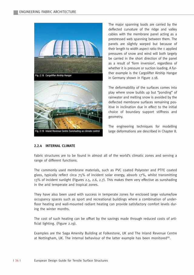
The major spanning loads are carried by thedeflected curvature of the ridge and valleycables with the membrane panel acting as aprestressed web spanning between them. Thepanels are slightly warped but because oftheir length to width aspect ratio the ± appliedpressures of snow and wind will both largelybe carried in the short direction of the panelas a result of ‘form inversion’, regardless ofwhether it is pressure or suction loading. A fur-ther example is the Cargolifter Airship Hangarin Germany shown in Figure 2.18.
The deformability of the surfaces comes intoplay where snow builds up but “ponding” ofrainwater and melting snow is avoided by thedeflected membrane surfaces remaining pos-itive in inclination due in effect to the initialchoice of boundary support stiffness andgeometry.
The engineering techniques for modellinglarge deformations are described in Chapter 8.
2.2.4 INTERNAL CLIMATE
Fabric structures are to be found in almost all of the world’s climatic zones and serving arange of different functions.
The commonly used membrane materials, such as PVC coated Polyester and PTFE coatedglass, typically reflect circa 75% of incident solar energy, absorb 17%, whilst transmitting13% of incident sunlight (Figures 2.5, 2.6, 2.7). This makes them very effective as sunshadingin the arid temperate and tropical zones.
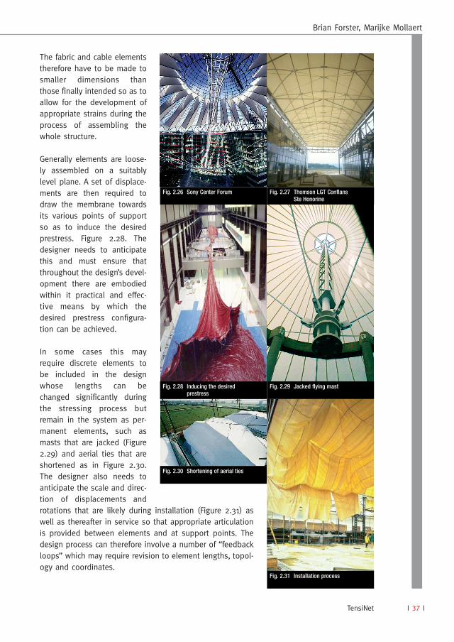
They have also been used with success in temperate zones for enclosed large volume/lowoccupancy spaces such as sport and recreational buildings where a combination of under-floor heating and wall-mounted radiant heating can provide satisfactory comfort levels dur-ing the winter months.
The cost of such heating can be offset by the savings made through reduced costs of arti-ficial lighting. (Figure 2.19).
Examples are the Saga Amenity Building at Folkestone, UK and The Inland Revenue Centreat Nottingham, UK. The internal behaviour of the latter example has been monitored10.
European Design Guide for Tensile Surface Structures
Fig. 2.18 Cargolifter Airship Hangar
Fig. 2.19 Inland Revenue Centre Sunshading as climate control

I 35 I
Other strategies can involve trapping air between multiple layers of membrane such as inthe Cargolifter Airship Hanger. In this project there are 4 layers of PVC coated polyesterassembled so as to create 2 sealed volumes of air. This results in a thermal transmissionthought to be comparable with a U-value of 0.95W/m2K and a light transmission of 1.5%.(Figure 2.20). Extra membrane layers of course erode the % of natural light transmitted.
The roofs over the Museum of Science and Industry at La Villette in Paris (completed 1986)and the Lindsay Park Aquatic Centre in Calgary (completed 1984), both involve the use of a400mm thickness of translucent glass filament insulation and transparent vapour barriersplaced between an outer and an inner layer of PTFE coated glass. This gives each roof athermal transmission thought to be comparable to a U-value of 0.4W/m2 and a light trans-mission of 3.5%.
A discussion of environmental behaviour and the parameters influencing it is provided inChapter 4.
2.3 Design Sequence
2.3.1 CONCEPTUAL DEVELOPMENT
The Client’s brief and the nature and con-figuration of the site need to be fully con-sidered and understood. Within the briefthere may be space and climate require-ments which could be fulfilled by beingenclosed with a fabric structure and thearchitectural form of such a roof may respond harmoniously with the topographical qualities ofthe surrounding terrain. Can the Client’s brief be met satisfactorily by an open-sided canopy oris an enclosed building required? Open sided canopies provide much more freedom in choiceof shape and configuration, and they can be built to less exacting tolerances of final position.(Figure 2.21 plus examples in Chapter 3). Bringing an enclosing wall up to such a canopy needsto accommodate quite large displacements of the roof which, according to circumstances couldbe as large as ± 500mm due to wind or snow loading. A variety of folding mechanisms madefrom membrane material have been employed to effect such closure. They need to be lightlytensioned for reasons of appearance and stability. (Figures 2.22, 2.23 and Chapter 3).
Brian Forster, Marijke Mollaert
TensiNet
Fig. 2.20 Extra membrane layers Fig. 2.21 Open sided canopy
Fig. 2.22 Folding mechanism mock-up

ENGINEERING FABRIC ARCHITECTURE
I 36 I
On the other hand if a fabric structure is toform part of the enclosing skin of a buildingthe opportunity may exist to geometricallyintegrate the two so that, like the RaleighArena and others such as the Saga building,the membrane’s tensile forces are largelyand economically absorbed within the build-ing’s framework (as opposed to heavyground anchorages) and sealing betweenwall and roof is relative simple (Figure 2.24).Other examples are the Munich AirportCentre (Figure 2.25), the Sony Center Forumroof in Berlin (Figure 2.26) and ThomsonLGT at Conflans St. Honorine. Figure 2.27.
Geographical location has a very direct bear-ing on the type and magnitude of loadingwhich a fixed non-retractable roof mustsupport. Design values for wind and snowhave to be derived via National Standards,the meteorological records of the site, andwhere necessary through wind tunnel modeltesting. For structures of significant sizemodel testing should be an essentialrequirement. Refer to Chapter 7 for expand-ed discussion on the choice of suitableloading patterns and loading intensity.
Membrane materials are easy to cut with asharp knife and are therefore susceptible toaccidental damage from vandalism and flyingobjects. As with conventional structures theaccidental removal of individual members ormembrane panels needs investigation todemonstrate the inherent damage limitationof the whole system. Whilst such accidentaldamage is quite rare, a sound and regularsystem of inspection should be implementedby owners so as to pre-empt the occurrenceof serious damage. Designers therefore needto anticipate the need for access. Chapter 10provides further information.
A fabric structure is composed entirely of pre-fabricated elements which once assembledforms a prestressed system with its own par-ticular geometry and prestress distribution.
European Design Guide for Tensile Surface Structures
Fig. 2.23 Dynamic Earth Centre, Interface of wall and membraneroof
Fig. 2.24 Saga Headquarters Building
Fig. 2.25 Munich Airport Centre
I 37 I
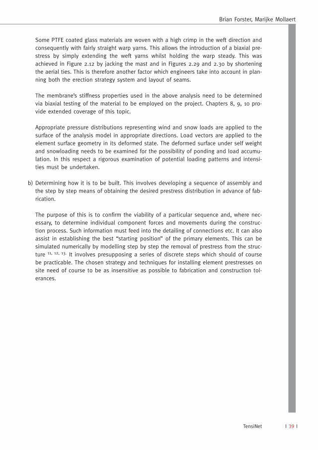
The fabric and cable elementstherefore have to be made tosmaller dimensions thanthose finally intended so as toallow for the development ofappropriate strains during theprocess of assembling thewhole structure.
Generally elements are loose-ly assembled on a suitablylevel plane. A set of displace-ments are then required todraw the membrane towardsits various points of supportso as to induce the desiredprestress. Figure 2.28. Thedesigner needs to anticipatethis and must ensure thatthroughout the design’s devel-opment there are embodiedwithin it practical and effec-tive means by which thedesired prestress configura-tion can be achieved.
In some cases this mayrequire discrete elements tobe included in the designwhose lengths can bechanged significantly duringthe stressing process butremain in the system as per-manent elements, such asmasts that are jacked (Figure2.29) and aerial ties that areshortened as in Figure 2.30.The designer also needs toanticipate the scale and direc-tion of displacements androtations that are likely during installation (Figure 2.31) aswell as thereafter in service so that appropriate articulationis provided between elements and at support points. Thedesign process can therefore involve a number of “feedbackloops” which may require revision to element lengths, topol-ogy and coordinates.
Brian Forster, Marijke Mollaert
TensiNet
Fig. 2.26 Sony Center Forum Fig. 2.27 Thomson LGT ConflansSte Honorine
Fig. 2.28 Inducing the desiredprestress
Fig. 2.29 Jacked flying mast
Fig. 2.30 Shortening of aerial ties
Fig. 2.31 Installation process

ENGINEERING FABRIC ARCHITECTURE
I 38 I
According to circumstances the designer may explore theseissues in the first instance with scale physical models(Figure 2.32). Analytical modelling can provide confirmationof the forces applied to the elements in the system at var-ious stages during erection and prestressing.
2.3.2 DETAILED DESIGN
The detailed design process involves several stages, and isinvariably based around the use of geometrically non-lin-ear analysis software. This process can be summarised inthe following three steps:
a) Developing the design concept. This involves defining aphysical configuration of elements, defining materialsand their strength and stiffness properties, elementsizes; defining the connections between all elements.An “equilibrium form” needs to be established usingzero-stiffness finite elements representing the mem-brane and cables each of which have specified tensions. By changing the relative valuesof tensions and the relative geometry of the supports, different surface geometries result.This can be advantageous in accommodating, for instance, the dominance of a particu-lar service load, and in improving areas that may be prone to ponding or inversion.
In the structural analysis that follows the form finding stage, cable and membrane ele-ments with real stiffness values are used; particular elements whose tensions go to zeroare automatically switched out during the analysis to simulate a slack cable or buckledmembrane. The element meshes used in the computer model are aligned with the direc-tions of weave and anticipate the position and direction of the seams between the indi-vidual panels of fabric that will make up the whole surface.
It is important to note that the positioning and direction of seams over the membrane’ssurface is never arbitrary or merely a matter of taste, except in the most lightly loadedstructures.
The seams are an indication of the direction of the warp yarns. Since in most cloths thewarp direction is stronger than the weft, the warp would be placed to follow the higherstresses for reasons of economy (Figure 2.19).
In regions of significant snow loading the warp would generally be chosen to follow thesagging curvature so that its greater stiffness can limit snow load deflections in the medi-um to long term.
Where wind loads are significantly higher than snow loads then it can make sense to theplace the seams in the arching direction. (Figures 2.19, 2.23).
European Design Guide for Tensile Surface Structures
Fig. 2.32 Scale model
I 39 I
Some PTFE coated glass materials are woven with a high crimp in the weft direction andconsequently with fairly straight warp yarns. This allows the introduction of a biaxial pre-stress by simply extending the weft yarns whilst holding the warp steady. This wasachieved in Figure 2.12 by jacking the mast and in Figures 2.29 and 2.30 by shorteningthe aerial ties. This is therefore another factor which engineers take into account in plan-ning both the erection strategy system and layout of seams.
The membrane’s stiffness properties used in the above analysis need to be determinedvia biaxial testing of the material to be employed on the project. Chapters 8, 9, 10 pro-vide extended coverage of this topic.
Appropriate pressure distributions representing wind and snow loads are applied to thesurface of the analysis model in appropriate directions. Load vectors are applied to theelement surface geometry in its deformed state. The deformed surface under self weightand snowloading needs to be examined for the possibility of ponding and load accumu-lation. In this respect a rigorous examination of potential loading patterns and intensi-ties must be undertaken.
b) Determining how it is to be built. This involves developing a sequence of assembly andthe step by step means of obtaining the desired prestress distribution in advance of fab-rication.
The purpose of this is to confirm the viability of a particular sequence and, where nec-essary, to determine individual component forces and movements during the construc-tion process. Such information must feed into the detailing of connections etc. It can alsoassist in establishing the best “starting position” of the primary elements. This can besimulated numerically by modelling step by step the removal of prestress from the struc-ture 11, 12, 13. It involves presupposing a series of discrete steps which should of coursebe practicable. The chosen strategy and techniques for installing element prestresses onsite need of course to be as insensitive as possible to fabrication and construction tol-erances.
Brian Forster, Marijke Mollaert
TensiNet

ENGINEERING FABRIC ARCHITECTURE
I 40 I
2.3.3 FABRICATION INFORMATION
Accurate fabrication dimensions are essential to the successful construction of fabric struc-tures. This requires membrane cutting patterns to be taken out of the “at prestress” modelof the structure. Seam lines between panels of cloth are defined by geodesic lines for effi-ciency in material use. Patterns have to be “compensated”, that is shrunk by percentagevalues in both warp and weft directions so as to allow for the development of strains nec-essary to give prestress. Batch testing of the fabric to be used in the work has to be car-ried out to determine these values. Local adjustments to edge lengths (“decompensation”)are often made at some boundaries, e.g. continuous beam edges, to facilitate safe installa-tion. Chapters 8 and 9 describe this process in more detail13.
In addition to the fabric related items, schedules will also be required for accurately dimen-sioning cables, taking into account stretch compensations and adjustment details. The shopdrawings for metalwork items including membrane plates and support masts and frameshave to be developed, and these should take into account final form geometry and angles.
Accuracy in both the dimensioning and the cutting out of individual fabric panels is impor-tant since gross errors will prevent the development of the intended strains and thereforethe required prestress. In addition the membrane’s finished appearance may be impaired bythe formation of folds and wrinkles.
Accuracy is important as it is generally not possible to correct errors on site.
Further description of how designers move from outline ideas to construction drawings isgiven in Chapters 3 and 5.
European Design Guide for Tensile Surface Structures
I 41 I
2.4 References
(1) IL16, “Zelte-Tents”, Institut fur Leichte Flachentragwerke, University of Stuttgart1976.
(2) I. G. Liudkovsky “On the choice of optimum types of suspended roofs.....” IASSColloquium, Paris 1962.
(3) B. Forster “Cable and Membrane Roofs – A Historical Survey” StructuralEngineering Review Vol. 6 No. 3-5 1994.
(4) F. Otto and R. Trostel, “Tensile Structures” Vol 2, MIT Press, 1967.
(5) IL18 Seifenblasen – Forming Bubbles, Institut fur Leichte Flachentragwerke,University of Stuttgart 1976.
(6) A. S. Day “A general computer technique for form finding for tension structures,IASS Conference, Shells and Spatial Structures, the Development of Form,Morgantown, USA, 1978.
(7) W. I. Liddell, “Minnesota Metrodome. A Study of the Behaviour of Air SupportedRoofs under Environmental Loads”, Structural Engineering Review Vol. 6, no. 3-4.
(8) K. Ishii, “Membrane Structures in Japan” SPS Publishing Tokyo, 1995.
(9) K. Ishii, “Membrane Designs and Structures in the World” Shinkenchiku-shaTokyo, 1999.
(10) J. C. Chilton, D. Devulder, “Environmental Monitoring at the Inland RevenueAmenity Building, Nottingham” – Designing Tensile Architecture – TensinetSymposium, VUB Brussels 2003.
(11) M. L. Brown, “Denver International Airport Tensile Roof Case Study – The Fabricationand Construction Process” – Proceedings of IASS-ASCE Symposium 1994.
(12) B. Forster, “The Integration of Large Fabric Structures within Building Projectsincluding the Significance of Design and Procurement Methods” – Proceedingsof IASS – LSAA Symposium 1998.
(13) D. Campbell, “The Unique Role of Computing in the Design and Constructionof Tensile Membrane Structures”, Proceedings of ASCE Second Civil EngineeringAutomation Conference, New York, 1991.
(14) D. Wakefield, A Bown, “Marsyas – A Large Fabric Sculpture : ConstructionEngineering and Installation” – Proceedings of Textile Composites and DeflatableStructures Conference, Ed. E. Onate, B. Kroplin CIMNE, Barcelona 2003.
Brian Forster, Marijke Mollaert
TensiNet
ENGINEERING FABRIC ARCHITECTURE
I 42 I
2.5 Picture Credits
Figure 2.1 I. L. ArchivFigure 2.2 The Architectural Association, LondonFigures 2.3, 2.4 M. R. BarnesFigure 2.5 Owens Corning Corp.Figures 2.6, 2.7 ArupFigure 2.8 Arup SAFigure 2.9 I. L. ArchivFigure 2.10 ArupFigure 2.11 Brian ForsterFigure 2.12 BirdairFigures 2.13, 2.14 ArupFigure 2.15 M. R. BarnesFigure 2.16 ArupFigure 2.17 KajimaFigure 2.18 SIATFigure 2.19 ArupFigure 2.20 SIATFigure 2.21 ArupFigure 2.22 BirdairFigure 2.23 ArupFigure 2.24 ArupFigure 2.25 Jens WillebrandFigure 2.26 Ralph Richter/architectur photoFigure 2.27 ArupFigure 2.28 ArupFigure 2.29 Tony SmithFigures 2.30, 2.31, 2.32 Arup
European Design Guide for Tensile Surface Structures