engineering geological practice in hong … · 4.2.3 folds and metamorphic structures 55 4.2.4 . in...
TRANSCRIPT

1
2
GEO PUBLICATION No. 1/2007
ENGINEERING GEOLOGICAL PRACTICE IN HONG KONG
GEOTECHNICAL ENGINEERING OFFICE Civil Engineering and Development Department The Government of the Hong Kong Special Administrative Region

GEO PUBLICATION No. 1/2007
ENGINEERING GEOLOGICAL PRACTICE IN HONG KONG
GEOTECHNICAL ENGINEERING OFFICE Civil Engineering and Development Department The Government of the Hong Kong Special Administrative Region

© The Government of the Hong Kong Special Administrative Region
First published, March 2007
Geotechnical Engineering Office, Civil Engineering and Development Department, Civil Engineering and Development Building, 101 Princess Margaret Road, Homantin, Kowloon, Hong Kong.
Captions of Figures on the Front Cover:
Top Left Example of an initial geological model based on an interpretation of published geological maps (see Section 3.2.1)
Top Right Irregular rockhead and corestone development influenced by faulting and jointing at a site in northeast Kowloon (see Section 4.4.4)
Bottom Left Outlines of debris trails from notable natural terrain landslides that occurred above Area 19, Tuen Mun (see Section 6.3.7)
Bottom Right Moderately-inclined southwest face of the Route 3 Ting Kau cutting which was influenced by adverse geological structures (see Section 6.4.4)
2


STEERING COMMITTEE AND WORKING GROUP
STEERING COMMITTEE:
GEO, Civil Engineering and Development Department R.K.S. Chan (Chairman) Y.C. Chan S.H. Mak J.B. Massey M.C. Tang R.P. Martin H.N. Wong K.C. Ng (Secretary)
WORKING GROUP:
GEO, Civil Engineering and Development Department H.N. Wong (Chairman) K.K.S. Ho R.P. Martin H.C. Chan S. Parry K.C. Ng (Secretary)
Association of Geotechnical and Geoenvironmental Specialists (HK) G. Jardine
Geological Society of Hong Kong A. Aydin
Geological Society of London (HK Regional Group) M. Free, N. Koor and M. Devonald (at different periods)
Hong Kong Institution of Engineers (Geotechnical Division) I. Askew
Institute of Materials, Minerals and Mining (HK Branch) M. Smith and M. Wright (at different periods)
Institute of Quarrying (HK Branch) P. Fowler
4

CONTENTS
Page
TITLE PAGE 1
FOREWORD 3
CONTENTS 5
1. INTRODUCTION 22
1.1 Purpose and Scope 22
1.2 Layout 22
1.3 Limitations 23
2. INTRODUCTION TO ENGINEERING GEOLOGICAL PRACTICE 24
2.1 Introduction 24
2.2 Definition 24
2.3 Existing Guidance on Engineering Geological Practice 25
2.4 Recommendations for Improvements in Engineering Geological Practice 25
3. ENGINEERING GEOLOGICAL INPUT TO GEOTECHNICAL WORKS 27
3.1 Model Approach 27
3.1.1 Introduction 27
3.1.2 Geological Model 28
3.1.3 Ground Model 29
3.1.4 Design Model 29
3.1.5 Application 31
3.2 Desk Study and Site Reconnaissance 31
3.2.1 Introduction 31
3.2.2 Geological Maps 32
3.2.3 Aerial Photograph Interpretation 33
3.2.4 Site Reconnaissance 34
3.2.5 Synthesis of the Initial Geological Model 34
3.3 Engineering Geological Mapping 36
3.3.1 Introduction 36
5
3.3.2 Approach 37
3.3.3 Fieldwork 37
3.3.4 Presentation 38
3.4 Sub-surface Exploration 39
3.4.1 Introduction 39
3.4.2 Existing Guidance 40
3.4.3 Ground Investigation 40
3.4.4 Hydrogeological Investigation 45
3.4.5 Storage and Handling of Data 46
3.4.6 Updating the Geological Model 46
3.5 Geotechnical Characterisation 46
3.5.1 Introduction 46
3.5.2 Material Properties 47
3.5.3 Properties of Discontinuities 47
3.5.4 Mass Properties 48
3.5.5 Characterisation of Hydrogeological Properties 50
3.6 Model Development during Design and Construction 51
3.6.1 Development during Design 51
3.6.2 Verification during Construction 51
4. GEOLOGICAL PROCESSES AND ENGINEERING IMPLICATIONS 52
4.1 Introduction 52
4.2 Tectonics and Tectonic Structures 52
4.2.1 Introduction 52
4.2.2 Faults 52
4.2.3 Folds and Metamorphic Structures 55
4.2.4 In situ Stress 55
4.2.5 Tectonic Joints 56
4.3 Metamorphism and Hydrothermal Alteration 57
4.3.1 Introduction 57
4.3.2 Dynamic Metamorphism 58
4.3.3 Contact Metamorphism 58
4.3.4 Hydrothermal Alteration 59
4.4 Weathering 60
6

4.4.1 Introduction 60
4.4.2 Mechanical Disintegration 61
4.4.3 Chemical Weathering 61
4.4.4 Mass Effects 64
4.4.5 Variation in Engineering Rockhead 68
4.4.6 Subsurface Processes 69
4.5 Geomorphological Processes 73
4.5.1 Introduction 73
4.5.2 Geomorphology 73
4.5.3 Mass Movement 77
4.5.4 Fluvial Processes 78
4.5.5 Coastal and Offshore Processes 78
4.5.6 Influence of Quaternary Fluctuations in Sea-level 79
4.6 Hydrogeological Processes 79
4.6.1 Introduction 79
4.6.2 Hydrogeological Environments 79
4.6.3 General Hydrogeological Characteristics 80
4.6.4 Groundwater in Slopes 80
4.6.5 Groundwater affected by Tunnelling 85
4.6.6 Hydrogeological Uncertainty 85
5. ENGINEERING GEOLOGY OF HONG KONG ROCKS AND SOILS 86
5.1 Introduction 86
5.2 Plutonic Rocks 86
5.2.1 Introduction 86
5.2.2 Engineering Geological Considerations 87
5.2.3 Material Characteristics 89
5.2.4 Mass Characteristics 90
5.3 Volcanic Rocks 93
5.3.1 Introduction 93
5.3.2 Engineering Geological Considerations 93
5.3.3 Tuff Material Characteristics 94
5.3.4 Tuff Mass Characteristics 97
5.3.5 Tuff Material Uses 97
7
5.3.6 Lava 98
5.3.7 Other Volcanic Rocks 98
5.4 Dyke Rocks 99
5.4.1 Introduction 99
5.4.2 Engineering Geological Considerations 99
5.4.3 Origin and Occurrence of the Dyke Rocks 100
5.4.4 Material Characteristics 100
5.4.5 Mass Characteristics 100
5.4.6 Case Studies 101
5.5 Marble and Marble-bearing Rocks 102
5.5.1 Introduction 102
5.5.2 Engineering Geological Considerations 103
5.5.3 Material Characteristics 103
5.5.4 Mass Characteristics 106
5.5.5 Engineering Issues 110
5.6 Sedimentary Rocks 111
5.6.1 Introduction 111
5.6.2 Engineering Geological Considerations 112
5.6.3 Material and Mass Characteristics 113
5.7 Metamorphic Rocks 114
5.7.1 Introduction 114
5.7.2 Engineering Geological Considerations 114
5.7.3 Case Studies 115
5.8 Superfi cial Deposits 116
5.8.1 Introduction 116
5.8.2 Quaternary Palaeo-environments 117
5.8.3 Terrestrial Deposits 117
5.8.4 Pleistocene Marine Deposits 121
5.8.5 Holocene Marine Deposits 121
5.9 Made Ground 123
5.9.1 Introduction 123
5.9.2 Historical Reclamations and Fill Platforms on Low-lying Terrain 124
5.9.3 Development Platforms and Roads on Sloping Terrain
8
124

125 5.9.4 Case Studies
6. ENGINEERING APPLICATIONS 129
6.1 Introduction 129
6.2 Natural Terrain Hazard Studies 129
6.2.1 Introduction 129
6.2.2 Geological Models 131
6.2.3 Hazard Models 132
6.2.4 Hazard Assessment 137
6.3 Site Formation 144
6.3.1 Introduction 144
6.3.2 Material Classification 144
6.3.3 Rock Mass Characterisation 144
6.3.4 Blasting 146
6.3.5 Hydrogeology 149
6.3.6 Rehabilitation of Rock Faces 149
6.3.7 Site Formation in Tuen Mun Area 19 151
6.4 Slope Stability 157
6.4.1 Introduction 157
6.4.2 Relict Instability 158
6.4.3 Previous Failures and Deterioration of Man-made Slopes 161
6.4.4 Adverse Discontinuities 164
6.4.5 Hydrogeological Boundaries 175
6.4.6 High Groundwater Levels in Deep Weathering Profiles 176
6.4.7 Complex Hydrogeological Conditions 176
6.4.8 Difficulties during Installation of Soil Nails 181
6.5 Foundations 184
6.5.1 Introduction 184
6.5.2 Shallow Foundations on Soil 184
6.5.3 Shallow Foundations on Rock 186
6.5.4 Pile Foundations on Rock 187
6.5.5 Friction Pile Foundations in Soil 193
6.5.6 Foundations on Marble 193
6.6 Deep Excavations 196
9
6.6.1 Introduction 196
6.6.2 Excavation and Support Types 196
6.6.3 Risk Management and Engineering Geological Input 196
6.6.4 Excavations in Rock 197
6.6.5 Excavations in Soil 198
6.7 Tunnels and Caverns 200
6.7.1 Introduction 200
6.7.2 Methods of Excavation and Types of Lining 203
6.7.3 Adverse Geological Structures 204
6.7.4 Assessment of Rock Mass Quality 209
6.7.5 Mixed Ground Conditions 217
6.7.6 Hydrogeology 221
6.7.7 Caverns 225
6.8 Marine Works and Reclamation 229
6.8.1 Introduction 229
6.8.2 Reclamations, Seawalls and Breakwaters 230
6.8.3 Case Study - Hong Kong International Airport Reclamation 232
6.8.4 Mud Dredging for Navigation Channels and Anchorages 236
6.8.5 Marine Disposal of Mud 237
6.8.6 Beach Replenishment 238
6.8.7 Unexploded Ordnance 239
6.9 Landfill and Contaminated Land 239
6.9.1 Introduction 239
6.9.2 Landfills 240
6.9.3 Contaminated Land 241
6.10 Assessment of Natural Resources 242
6.10.1 Introduction 242
6.10.2 Hard Rock 242
6.10.3 Fill Material 245
6.10.4 Environmental Considerations 249
6.10.5 Disused Mines 251
7. REFERENCES
10
254

43
FIGURES AND TABLES Page Page
List of Figures
3.1.1 International perspective on the positions of engineering geology, soil mechanics and rock mechanics within ‘geo-engineering’ practice (after Bock, 2006) 27
3.1.2 Main elements of the geological model (Bock, 2006) 28
3.1.3 Typical development and application of the ‘Model Approach’ for a major project 30
3.2.1 Example of a geological model based on a desk study (Parry et al., 2004b) 32
3.2.2 Example of a geological model based on site reconnaissance (Parry et al., 2004b) 33
3.2.3 Regolith units and photogeological lineament overlain on an oblique aerial photograph (MFJV, 2002) 35
3.2.4 Construction of strike lines on photolineament to determine dip of fault or geological boundary 36
3.2.5 Rockhead contours assuming fault and major joint control of penetrative weathering 36
3.3.1 Composite extract from maps of the Chai Wan Engineering Geology Area Study (Martin, 2003 after Campbell et al., 1998) 38
3.3.2 Example of a structural domain summary plot for the Route 3 Tai Lam Tunnel 39
3.4.1 Example of regolith thickness in steeply-sloping terrain inferred from 3-D gravity model (Collar et al., 2000) 41
3.4.2 Comparison of two logs for the same trial pit (after Parry & Campbell, 2003) 42
3.4.3
3.4.4
3.4.5
3.5.1
3.5.2
3.5.3
3.5.4
4.2.1
4.2.2
4.2.3
4.2.4
Comparison of as-reported and as-corrected stereoplots of joint data for the same inclined drillhole core
Comparison of mapping data and acoustic televiewer data for the same quarry 43
Example of cross-hole seismic testing showing increase in apparent rock mass quality from 0 m to 15 m depth (after Bachy Soletanche, 2001) 44
Influence of specimen size on strength of ‘intact’ rock (Hoek, 2000) 47
Scale effect on the characteristics of discontinuous rock masses (Hoek, 2000) 48
Candidate failure surface involving a number of different shear failure mechanisms (Hoek et al., 2000) 49
Typical internal shears required to permit movement in a non-circular slide (Hutchinson, 1987) 49
Simplified geological map of Hong Kong (Fyfe et al., 2000) 53
Reidel shears within a major strike-slip fault zone (after Fookes et al., 2000 – based on Park, 1997) 54
Schematic section of a brittle-ductile fault zone (“Rambler Channel Fault”) encountered in the Harbour Area Treatment Scheme (HATS) Tunnel ‘F’ between Tsing Yi and Stonecutters Island (Sewell et al., 2000) 54
Zone of deep weathering at Tung Chung (inferred from boreholes and gravity survey) in meta-sediment and marble xenolith-bearing granite (Sewell & Kirk, 2000) 55
11

Page Page
4.2.5 Maximum horizontal stress ratio KH (SH/Sv) versus depth and orientations of SH (alignment of red bars in the photograph) in Hong Kong (selected data from Free et al., 2000 and Route 10 investigations)
4.2.6 Similarity in geological structure between Tsing Lung Tau and Ting Kau shown by contoured stereoplots of mapped discontinuities (major fault strikes shown on the Tsing Lung Tau plot for reference)
4.3.1 Cleavage/foliation zones in the northern New Territories (Sewell et al., 2000)
4.3.2 Development of contact metamorphic effects along a granite/tuff contact zone near Victoria Peak, Hong Kong Island (Strange & Shaw, 1986)
4.3.3 Hornfels close to the contact between granite and tuff near Victoria Peak, Hong Kong Island (note extensive recrystallisation and the development of spotting)
4.3.4 Kaolinised granite core from the 1997 Ville de Cascade landslide site at Fo Tan (HAPL, 1998a)
4.4.1 Sub-horizontal fractures in a granite core due to stress relief (Fletcher, 2004)
4.4.2 Six-fold classification of material decomposition, processes and effects in a sub-tropical environment
4.4.3 Variation in mineralogical and pore composition with decomposition in a typical granite (Irfan, 1996b)
4.4.4 Grades and characteristics of granitic rock material subject to primarily chemical decomposition processes (after Irfan, 1996b)
4.4.5 Sharply-defined rockhead with little corestone development in volcanic rock. A possible kaolin-rich zone lies directly above rockhead (Fyfe et al., 2000) 64
56 4.4.6 Corestone development influenced
by looseness of the rock mass on the hanging-wall side of a fault in northwest Kowloon (Whiteside, 1988) 65
57 4.4.7 Schematic PW weathering scheme applied to a mass exposure and other possible boundaries based on engineering requirements (after
58 GCO, 1988a) 66
4.4.8 Schematic depiction of rock percentage and correlation with rock core recovery (assuming recovery of
59 100% of the rock material). Very idealised jointing patterns and equidimensional blocks are shown. The percentage of rock in the ground in proportion to the percentage of rock core recovered will be larger with increasing randomness in block
59 arrangement and increasingly poor drilling practice 67
4.4.9 Schematic geological map and 60 section developed from borehole
data and local geological knowledge showing highly variable rockhead surface (Fletcher, 2004) 68
61 4.4.10 Soil pipe about 1 m across, near
the colluvium/saprolite interface at Lai Ping Road Landslide (Koor &
62 Campbell, 2005) 69
4.4.11 Soil pipe development and its effects on groundwater regimes (Nash &
62 Dale, 1984) 70
4.4.12 Schematic representation of redirection of pipe flow in a blocked system (Nash & Dale, 1984) 70
63
12

4.4.13 Voids/soil pipes at the colluvium/ bedrock interface in a landslide scar
4.4.14 Bedded granular material infilling sheeting joint
4.4.15 Typical appearance of a thick kaolin infill in granite
4.4.16 August 1995 Shum Wan Road landslide (GEO, 1996b and Kirk et al., 1997)
4.4.17 1972 Lai Cho Road landslide (MGSL, 2002 and Thorn et al., 2003)
4.5.1 Geological model for landscape evolution in Hong Kong (Hansen, 1984)
4.5.2 Geological model of the eastern flank of Tsing Shan showing the interaction of geology, topography and geomorphology on landslide initiation, transport and deposition processes (Fletcher et al., 2002)
4.5.3 The 1990 Tsing Shan debris flow
4.5.4 Typical natural terrain hazards in Hong Kong (GEO, 2000)
4.5.5 Debris avalanches and debris flows below steep cliff near Ngong Ping, Lantau
4.6.1 Silty clay with sand laminae and lenses from the Chek Lap Kok Formation (Fyfe et al., 2000)
4.6.2 Schematic hydrogeological processes above the rockhead in a cut slope (after Hencher, 2000)
4.6.3 Results of automatic groundwater monitoring at shallow depth in natural terrain (Evans & Lam, 2003b)
Page
71
71
72
72
73
74
75
76
77
77
79
81
81
4.6.4
4.6.5
4.6.6
4.6.7
4.6.8
4.6.9
5.2.1
5.2.2
5.2.3
5.3.1
5.3.2
Groundwater responses in colluvium and a weathered granite profile in the Mid-levels study area of Hong Kong Island (after GCO, 1982)
Conceptual model of high permeability zone and confined groundwater below rockhead (after Jiao et al., 2003)
Conceptual model of possible hydrogeological influence on deep-seated failure of some cut slopes in Hong Kong (after Jiao, 2000a)
Automatic piezometer monitoring of rock slope sheeting joints for different rainstorms (Richards & Cowland, 1986)
Schematic model of primary and secondary porosity systems and groundwater compartmentalisation in a slope (Au, 1990)
Evidence of groundwater compartmentalisation from horizontal drain fl ow measurements (after Martin et al., 1995)
Distribution of the plutonic rocks in Hong Kong (Sewell et al., 2000)
Composition of the plutonic rocks (Sewell et al., 2000)
Failure along wavy stress relief joint surface in Tsing Shan granite (after HCL, 2001)
Distribution of the volcanic rocks in Hong Kong (after Sewell et al., 2000)
Classification of pyroclastic rocks (after Schmid, 1981 and Fisher & Schminke, 1984)
Page
82
83
83
84
84
84
86
87
92
94
96
13

Page Page
5.3.3 Bedded tuffaceous sedimentary rocks with variable grain size (conglomerate, sandstone, siltstone and mudstone) in the Mang Kung Uk Formation (Sewell et al., 2000) 99
5.4.1 Variation in grain size between decomposed mafic rock and decomposed granite (after Au, 1986) 101
5.4.2 Chilled contact margin of mafi c dyke rock against coarse ash tuff in NE Lantau (Li et al., 2000) 101
5.4.3 Schematic geology of proposed anchorage site of the Tsing Ma suspension bridge on Tsing Yi Island (after Langford, 1991) 101
5.4.4 Map of dyke outcrops on natural hillside above Lai Cho Road (MGSL, 2002 and Thorn et al., 2003) 102
5.4.5 Schematic geological model of the 1982 landslide on Tuen Mun Highway (Hencher, 2000) 102
5.5.1 Distribution of the Yuen Long Formation in the northwestern New Territories (after Sewell et al., 2000) 105
5.5.2 Marble extent below the Ma On Shan area (updated HKGS 1:20,000 scale geological Map Sheet 7, 2005) 106
5.5.3 Cross-section through the contact zone between marble and granite beneath the Ma On Shan reclamation (after Sewell, 1996) 107
5.5.4 Volcano-tectonic map of Hong Kong showing Tung Chung and Ma On Shan marble sub-crops and faults that were active during emplacement of the Lantau Volcanic Group and Kwai Chung Suite granitoid dyke swarms and plutons (Sewell & Kirk, 2002) 107
5.5.5
5.5.6
5.5.7
5.6.1
5.6.2
5.6.3
5.7.1
5.8.1
5.8.2
5.9.1
5.9.2
Schematic section through buried karst beneath the Yuen Long fl oodplain (Fyfe et al., 2000) 108
Complex fault zone between marble and granite at Ma On Shan showing deepest weathering and karst solution within the fault zone (Sewell et al., 2000) 109
Schematic representation of the development of karst deposits beneath Tower 5, Site 3, Tung Chung East Reclamation (Fletcher et al., 2000) 109
Distribution of the clastic sedimentary and meta-sedimentary rocks in Hong Kong (after Sewell et al., 2000) 112
Orientation of bedding planes in sandstone of the Pat Sin Leng Formation, at Wu Kau Tang Road (Irfan & Cipullo, 1988) 114
Section through the 1986-87 landslide at Wu Kau Tang Road (Irfan & Cipullo, 1988) 114
View of slope at Lin Ma Hang Road showing complex structural geology of the meta-sedimentary rocks in the Lok Ma Chau Formation, including recumbent folding and a minor fault across the slope 115
Schematic representation of the stratigraphy of Hong Kong superficial deposits (after Fyfe et al., 2000) 118
Seismic boomer profile showing acoustic blanking caused by gas associated with an intertidal channel (after Fyfe et al., 2000) 123
Triggers and contributory factors for fill slope failure (Sun, 1998) 126
View of the fill slope failure at Sau Mau Ping Estate in 1976 126
14

5.9.3 Cross-section through a fi ll slope below Tai Po Road showing location of soil nail grout loss zone
5.9.4 1949 aerial photograph showing the location of a fill slope below Tai Po Road prior to construction
6.2.1 Terrain units at Lei Pui Street (MGSL, 2004)
6.2.2 Process-based terrain unit model for the North Lantau Expressway NTHS (OAP, 2004b)
6.2.3 Terrain units and hazard models at Cloudy Hill (HCL, 2003b)
6.2.4 Geomorphological model for Tung Chung cable car NTHS (Mott Connell, 2003)
6.2.5 Progressive development of geological models for NTHS
6.2.6 Detailed mapping of the landslide scar at Lei Pui Street (MGSL, 2004)
6.2.7 Examples of landslide initiation factors (MFJV, 2004a).
6.2.8 Tsing Shan Foothills landslide frequency/magnitude for relict, recent and Year-2000 landslides on 100 year to 10,000 year time interval basis (MFJV, 2003c)
6.2.9 Analytical model of the Lei Pui Street channelised debris flow (MGSL, 2002)
6.3.1 Excavatability charts for granite and volcanic rock masses at Anderson Road Quarries (after Choy & Irfan, 1986)
6.3.2 Weak area 45 m southwest of the blast location near New Clear Water Bay Road (Massey & Siu, 2003)
Page
127
127
130
132
133
134
136
138
140
142
143
145
147
6.3.3 Inferred mechanism of flyrock occurrence (after Massey & Siu, 2003)
6.3.4 Blast-induced failure during site formation works at Sau Mau Ping Road in 1997 (Leung et al., 1999)
6.3.5 Section through the blast-induced failure at Sau Mau Ping Road (Leung et al., 1999)
6.3.6 Potential effect of reclamation works on raising the overall groundwater table (Jiao, 2000b)
6.3.7 Oblique aerial photograph of Tsing Shan and Area 19 showing recent major debris flow and debris flood scars, the 2003 slope treatment works and the 2003 debris flow mitigation measures (volumes refer to the cumulative erosion along the debris trails)
6.3.8 Geological setting in the vicinity of Area 19 (looking northwest)
6.3.9 Plan of Area 19 showing instability history
6.3.10 Section A–A through Area 19 showing geology, deep-seated movements and high groundwater table
6.3.11 Undulating Type 2 shear surface within completely decomposed andesite (photograph by N.P. Koor)
6.3.12 Close-up of a Type 2 shear surface with polished and slickensided surfaces and grey clay infill (photograph by N.P. Koor)
6.4.1 1972 Po Shan Road landslide
Page
148
149
150
150
152
153
154
155
156
156
157
15

Page Page
6.4.2 1995 Shum Wan Road landslide and clusters of relict and recent coastal instability identifi ed from API near Aberdeen (after Franks et al., 1999) 158
6.4.3 1997 Ma On Shan Road landslide 159
6.4.4 Previous instabilities near the 1997 Ma On Shan Road landslide inferred from API (HAPL, 1999) 159
6.4.5 1999 Shek Kip Mei Landslide 160
6.4.6 Section through the Shek Kip Mei landslide showing old, infilled tension cracks, deep weathering and weakness plane near toe (FMSW, 2000) 160
6.4.7 Laterally persistent discontinuity infilled with slickensided kaolin and manganese oxide deposits at the toe of the Shek Kip Mei landslide (FMSW, 2000) 161
6.4.8 1988 landslide at Island Road School (Irfan, 1989) 161
6.4.9 Previous instabilities near site of the 1988 landslide at Island Road School (after Irfan, 1994b) 161
6.4.10 Section through the 1988 landslide area at Island Road School (Irfan, 1989) 162
6.4.11 Location of previous failures near the 1998 northern and southern landslides which occurred during LPM works (after Premchitt, 1991; Wong, 1997; FSW, 2001a) 162
6.4.12 1987 landslide at Sai Sha Road with kaolin and manganese oxide coated relict discontinuities (Premchitt, 1991) 162
6.4.13 1995 landslide at Sai Sha Road with relict joints (Wong, 1997) 163
6.4.14 Slickensided, manganese oxide coated, subvertical relict joints forming the back-scarp to the 1998 landslide which occurred during LPM works to the 1995 landslide at the junction of Sai Sha and Tai Mong Tsai roads (FSW, 2001a) 163
6.4.15 Section through the 1998 landslide highlighting the large rise in groundwater level recorded by Halcrow buckets between July 1997 and August 1997 (FSW, 2001a) 163
6.4.16 2003 Orthophoto of the ‘Pepco’ slope near Nam Wan, South Tsing Yi showing previous distressed zones 164
6.4.17 Distressed ‘Pepco’ slope in 1982 165
6.4.18 Outwash from complete failure of the 1982 distressed zone of the ‘Pepco’ slope blocking Tsing Yi Road in 1983 following heavy rain (Choot, 1993b) 165
6.4.19 1982 South Bay Close landslide scar (Hencher, 1983b) 166
6.4.20 Variable appearance of the infi ll along the rupture surface of the South Bay Close landslide (Hencher, 1983b) 166
6.4.21 Section through the 1982 South Bay Close landslide showing projection of the infilled zone through boreholes (Hencher, 1983b) 167
6.4.22 1995 Fei Tsui Road landslide 168
6.4.23 Section through Fei Tsui Road landslide (GEO, 1996b) 168
6.4.24 Appearance of the kaolin-rich altered tuff in the rupture surface of the Fei Tsui Road landslide (GEO, 1996b) 168
6.4.25 Location of the 1995 Fei Tsui Road landslide in 1977 (B&P, 1977) 169
16

Page Page
6.4.26 Section through 1998 Tai Po Road landslide opposite Chak On Estate (FSW, 2001b) 169
6.4.27 Release plane and sandy silty clay layer exposed in trial pit during investigation of the 1998 Tai Po Road landslide (FSW, 2001b) 170
6.4.28 1982 photograph showing history of cut slope instability at Lin Ma Hang Road 170
6.4.29 1981 failure on undulating foliation planes plunging steeply towards cutting at Lin Ma Hang Road 171
6.4.30 Relict rupture surface exposed in trial pit in 2001. Overlying phyllite is highly disturbed and clayey sediment infill in underlying meta-sediments is concentrated along the foliation fabric and near the relict surface of rupture 171
6.4.31 Extract from the original 1981 geological face mapping record of the Lin Ma Hang Road cutting showing complex structure and weathering 172
6.4.32 Initial ‘box-cut’ of Ting Kau cutting showing continuous shear and persistent Set 1 joint planes (photograph by J.W. Tattersall) 173
6.4.33 Route 3 Ting Kau cutting showing moderately-inclined southwest face 174
6.4.34 Upper part of face during construction showing shear surface and Domains A and B (photograph by J.W. Tattersall) 174
6.4.35 View of completed cutting showing trace of main shear and Domains A and B 174
6.4.36 Analytical models for sensitivity analysis assuming a composite failure surface along the main shear plane and Set 1 joints, passing through the rock mass at the toe (Tattersall, 2006) 175
6.4.37 Intermittent failure and progressive, deeper-seated movements at Tin Wan Hill Road resulting from complex geological structure, weathering and hydrogeological regimes (after Irfan, 1986) 177
6.4.38 1997 shallow failures at Lai Ping Road and location of main scarp of older landslide (Sun & Campbell, 1999) 178
6.4.39 Extract of section through the Lai Ping Road landslide showing deep weathering, high groundwater and shear planes associated with deep-seated movements (Koor & Campbell, 2005) 179
6.4.40 Anomalous zone in saprolite interpreted as being either an infilled soil pipe or high permeability sheared zone (Koor & Campbell, 2005) 178
6.4.41 Seepage analysis of the 1997 Lai Ping Road landslide assuming higher permeability of sheared zone above rockhead and accounting for the effect of open relict joints and pre-existing tension cracks (Sun & Campbell, 1999) 180
6.4.42 1997 Ching Cheung Road landslide intersected by natural drainage line (HAPL, 1998b) 180
6.4.43 Section through 1997 Ching Cheung Road landslide showing previous failures and the large number of soil pipes encountered in drillholes (HAPL, 1998b) 181
17
Page Page
6.4.44 Hydrogeological model for development of erosion tunnels/soil pipes at Yee King Road (after HCL, 2003a) 182
6.4.45 Pipe erosion model for cut slopes in saprolite based on observations of slumped areas and tracer dye testing on the remediated large instability at Pun Shan Tsuen in 1985 (Nash & Chang, 1987) 183
6.5.1 Shallow foundations – potential geotechnical problems caused by geological variability in superficial deposits 185
6.5.2 Tsing Ma Bridge – geology of the Ma Wan Tower sites (Sewell, 1992) 187
6.5.3 Extract from an engineering geological plan for the West Dam foundation of High Island Reservoir (after Watkins, 1979) 188
6.5.4 Detail of the engineering geological plan and grouting layout for the groundwater cut-off beneath the core of the West Dam of the High Island Reservoir (after Watkins, 1979) 189
6.5.5 Piles to rock – potential problems associated with weathered seams 190
6.5.6 Piles to rock – potential problems associated with an irregular rockhead profile 191
6.5.7 Driven piles – potential problems caused by geological variability 192
6.5.8 Geological setting and site location plan of proposed tower block at Tung Chung (after 1:20,000-scale geological Map Sheet 9, GEO 1994) 193
6.5.9 Cross-section of the ground conditions beneath the proposed tower block in Tung Chung (after Fletcher et al., 2000). a. Mazier
sample of sedimentary breccia between blocks of completely decomposed feldsparphyric rhyolite. b. Soil pipe in completely decomposed feldsparphyric rhyolite. The pipe extends upwards from a layer of sedimentary breccia. c. Contact between granite and marble with sketch of relationships between rock types. d. Sedimentary breccia within cavity-fill material. e. Finely laminated clay and silt in cavity-fill material
6.5.10 Rockhead contour map of the site for the tower block and location of boreholes
6.6.1 Collapse of road due to boulders preventing adequate embedment of sheet piles retaining adjacent excavation
6.6.2 Initial excavations for the MTRC North Point plant building
6.6.3 MTRC North Point plant building during excavation showing limited support and occasional very persistent joints
6.6.4 Trace length distributions of joints (≥3 m) measured in MTRC North Point plant building and station excavations
6.6.5 Typical groundwater cut-off difficulties associated with irregular rockhead
6.6.6 Potential base heave in excavation due to confinement of groundwater in alluvium by overlying marine clay
6.6.7 Groundwater damming on hillsides due to deep excavations
6.7.1 Schematic plan of adverse geological structures encountered in HATS
194
195
197
198
198
198
200
201
201
18

Page
Stage 1 tunnels West of Tseung Kwan O (from as-built records) and faults and photolineaments from the 1:20,000-scale (GCO, 1986b) and 1:100,000-scale (Sewell et al., 2000) published geological maps 205
6.7.2 Summary of ground conditions and ground treatment works in HATS Stage 1 Tunnel ‘E’ 206
6.7.3 Layout plan of geological structures encountered in the Sha Tin Heights tunnel and faults and photolineaments inferred from detailed API and the 1:20,000-scale (GCO, 1986a) and 1:100,000-scale (Sewell et al., 2000) published geological maps 208
6.7.4 DB350 Tai Lam Tunnel location plan 211
6.7.5 West Rail Tai Lam Tunnel (northern section) – comparison of the tender design and as-built geological profiles (based on records provided by Nishimatsu-Dragages Joint Venture) 212
6.7.6 Water tunnel log 213
6.7.7 Graphical representation of relative tunnelling difficulty 216
6.7.8 Full face excavation, face reinforcement and forepoling (after Lunardi, 2000) 216
6.7.9 Full face excavation 216
6.7.10 Multiple headings 216
6.7.11 Full face excavation, face reinforcement and forepoling during construction (photograph by Nishimatsu-Dragages Joint Venture) 217
Page
6.7.12 Part of an as-built summary log for the Sham Tseng fault zone (provided by Nishimatsu-Dragages Joint Venture) 218
6.7.13 Section along the MTRC Island Line to the east of Admiralty Station showing irregular rockhead, corestones, coreslabs and the location of the 1981 Hennessy Road collapse at a steep soil/rock interface (based on as-built records from MTRC) 219
6.7.14 3-D models of a rock/soil interface based on logging of cuttings from drillholes for pre-reinforcement and grouting (models by Gammon Construction Ltd) 219
6.7.15 Typical layout of investigations for a marine tunnel crossing 220
6.7.16 Plan and section showing geological model and groundwater drawdown during rock tunnelling works (after Cowland & Thorley, 1985) 222
6.7.17 Groundwater drawdown in decomposed granite and settlement recorded adjacent to Star Ferry Car Park during rock tunnelling works (after Cowland & Thorley, 1985) 222
6.7.18 Hydrogeological setting of Tseung Kwan O Bay and HATS (Stage 1) Tunnel ‘C’ showing palaeovalley, faults encountered in tunnels, photolineaments and inferred faults 223
6.7.19 Tunnel ‘C’ volumetric joint frequency (Jv), fault locations and water inflow rate vs. chainage across Tseung Kwan O Bay 223
6.7.20 Geological sections showing inferred mechanism of reclamation under-drainage during tunnelling works (see Figure 6.7.18 for location of sections) 224
19
Page Page
6.7.21 Examples of large span tunnels and caverns in Hong Kong 226
6.7.22 Isometric drawing of Tai Koo MTR Cavern (Sharp et al., 1986) 227
6.7.23 Longitudinal section and plan of Tai Koo MTR cavern showing zonation (I to V) based on rock mass characteristics (Sharp et al., 1986) 228
6.7.24 Typical cavern sections, excavation stages and rock reinforcement (after Sharp et al., 1986) 228
6.8.1 Seismic boomer profile showing consolidation drapes of Sham Wat Formation sediment laid down on the gullied surface of the Chek Lap Kok Formation (Fyfe et al., 2000) 229
6.8.2 Schematic relationship between the seismo-stratigraphic units and seismic reflectors at the airport reclamation site (Plant et al., 1998 after James et al., 1994 – Copyright BGS / NERC) 233
6.8.3 A section showing the location of the weathered crust of the Chek Lap Kok deposits which was to form the founding layer for reclamation (Plant et al., 1998 after James et al., 1994 – Copyright BGS / NERC). See Figure 6.8.2 for an explanation of the seismo-stratigraphic units and seismic reflectors 234
6.8.4 An idealised CPT profile of the sea bed before the airport reclamation (Plant et al., 1998) 235
6.8.5 Interpretative seismic profi le showing the intended dredge level (in black) in areas of pre-Holocene drainage channels at the New Airport site,
Chek Lap Kok (after Covil & James, 1997 – Copyright BGS / NERC). See Figure 6.8.2 for an explanation of the seismo-stratigraphic units and seismic reflectors 236
6.8.6 Plan and section of large submarine landslide at East Ninepins mud disposal mound (Ng & Chiu, 2001) 238
6.10.1 Geological setting of Anderson Road Quarry 243
6.10.2 Geological setting of Shek O Quarry 244
6.10.3 Geological setting of Lam Tei Quarry 244
6.10.4 Location of marine borrow areas and volume of sand extracted (CEDD, 2005) 246
6.10.5 Plan layout and section through the West Po Toi marine borrow area (after DEMAS, 1996) 248
6.10.6 Photograph of alluvial sand and reworked alluvial sand from West Po Toi marine borrow area (BCL, 1991-93) 249
6.10.7 Satellite photograph of dredging plumes around the Po Toi Islands 250
6.10.8 Cross-section showing extent of underground mining and old subsided near-surface workings of the Needle Hill wolframite mine (after Roberts & Strange, 1991) 251
6.10.9 Black Hill Tunnels - Extract from the 1:20,000-scale geological map with mineral veins and adits associated with hydrothermal alteration highlighted 252
20

Page Page List of Tables
4.4.1 Terms for describing decomposition of feldspars (Irfan, 1996b) 62
4.4.2 Range of engineering properties within a completely decomposed granite weathering profi le (Martin, 2003) 64
4.4.3 Comparison of Geoguide 3 (GCO, 1988a) and Geotechnical Manual for Slopes (GCO, 1984) schemes for classifying weathered rock masses 66
5.2.1 Summary of material characteristics and properties for plutonic rocks 88
5.3.1 Summary of material characteristics and properties for volcanic rocks 95
5.3.2 Index properties of completely decomposed andesite (Koor et al., 2000) 98
5.5.1 Summary of material and mass characteristics of marble and marble-bearing rocks 104
5.5.2 Geotechnical issues associated with foundations on karst 110
5.5.3 Classification of marble rock mass based on MQD Values 111
5.8.1 Summary of alluvial material properties in Yuen Long area (after Beggs & Tonks, 1985) 121
5.8.2
6.7.1
6.7.2
6.7.3
6.7.4
6.7.5
6.7.6
6.7.7
6.7.8
Comparison of engineering properties of clayey and silty Holocene marine deposits in the Yuen Long basin area (after Beggs & Tonks, 1985) 122
Summary of typical bored tunnelling techniques for soft ground, mixed face and hard rock conditions 203
Comparison of Tunnel ‘F’ with other similarly excavated tunnel drives for HATS Stage 1 (after CDM, 2004) 208
Sha Tin Heights Tunnel Q-value ranges estimated at the preconstruction stage and from as-built records 210
West Rail Tai Lam Tunnel – comparison of pre-tender, tender and as-built estimates of rock mass Q-values 213
Geomechanics interpretation of the water tunnel log 214
Initial design parameter range and sensitivity analysis results 215
Cavern suitability classification (Roberts & Kirk, 2000) 225
Summary of selected examples of large span tunnels and caverns in Hong Kong 227
21

1. INTRODUCTION 1.1 PURPOSE AND SCOPE The purpose of this document is to introduce the principles of engineering geology as applicable to Hong Kong and to illustrate the application of these principles to civil engineering works, by means of examples and references. The document is aimed primarily at experienced geotechnical practitioners, to demonstrate the importance of engineering geology to the timely, cost effective and safe completion of civil engineering works. It will also assist experienced engineering geologists in Hong Kong by acting as an aide mémoire and will provide a valuable source of information for young and overseas practitioners.
The science of geology is concerned with the study of the natural materials and processes that have formed the Earth. A detailed understanding of this science allows representative geological models to be constructed from limited data to characterise what might otherwise appear to be chaotic and unpredictable ground.
Engineering geology provides the link between geology and engineering through the formation of geological models which can be used to identify geological hazards and uncertainty, plan effective ground investigations, and define blocks of ground and geological structures in an engineering context to facilitate geotechnical risk assessment and design. Knill (2002) considers that, to be successful, “engineering geology must demonstrate a balance between high-quality understanding of geology and a sufficient appreciation of engineering to ensure that the relevant information will be processed and communicated effectively”.
The amount of engineering geological input required for a particular civil engineering project varies depending on geological factors such as rock type, superficial deposits, geological structure and weathering as well as engineering considerations such as the type of scheme and the construction method adopted. This document provides a compendium of knowledge and experience of the various geological settings in Hong Kong in order that problematic conditions can be recognized in a timely fashion and the necessary engineering geological input can be obtained at the appropriate stage of a project.
1.2 LAYOUT Chapter 2 gives an introduction to current engineering geological practice in Hong Kong. In particular, it covers published guidance and areas identified for improvement with respect to reducing risk and uncertainty.
Chapter 3 deals with engineering geological input to geotechnical works. This involves the development of geological models and their refi nement during the engineering processes from planning to maintenance. Emphasis is placed on the value of the ‘model approach’ for effective anticipation and characterisation of the ground conditions in order to better manage the geotechnical risks. Data requirements at different stages of a project are outlined for reference, with focus on key elements critical for geotechnical investigations and design.
Chapter 4 summarises the basic geological processes that are pertinent to the understanding of the engineering properties of the rocks and soils in Hong Kong. The summaries are based on a consolidated review of documented knowledge and experience in Hong Kong and key references from elsewhere.
Chapter 5 describes the main types of rock and soil in Hong Kong and provides perspective on their engineering geological characteristics. Variations in chemical composition, mineralogy, lithology and block/particle size give rise to different weathering characteristics and geotechnical and hydrogeological properties. Where appropriate, reference to case studies which give insight into aspects of engineering geological interpretation and associated geotechnical problems is also given.
Chapter 6 presents key engineering geological issues and practices which are relevant to the main types of civil engineering applications. These are illustrated by reference to projects giving insight and focus to the engineering geological issues which may need to be considered. Some of the issues, practices and examples are relevant to several engineering applications, and cross-referencing has been used to avoid repetition.
22

1.3 LIMITATIONS The document is primarily based on a review of relevant literature and current practice. As such, information on certain topics may be limited in extent. Also, the level of information given for each lithological type is roughly proportional to their engineering importance and distribution with respect to development. Furthermore, owing to the wide range in the application of engineering geological practice, the document can only provide limited, albeit key, information with respect to relevant engineering geological considerations. However, where available, references are provided to allow more detailed information of each particular subject to be obtained if required.
The document is intended to enhance geotechnical practice in Hong Kong, and help geotechnical practitioners to recognise when specialist engineering geological expertise should be sought. The document is not intended to be used as a geotechnical standard, or used as a checklist for different types of engineering geological works. Furthermore, the document should not be regarded as a substitute for providing adequate engineering geological input.
Given the nature of the subject it is necessary to use geological terminology within the document, explained in simple terms where necessary. However, the purpose of the book is not to explain geology to engineers and it is expected that readers will obtain more detailed geological background material from other sources if required.
23

2. INTRODUCTION TO ENGINEERING GEOLOGICAL PRACTICE
2.1 INTRODUCTION Engineering geological practice is primarily concerned with the determination of geological and hydrogeological conditions to facilitate ground engineering with respect to the recognition and management of geotechnical risk. This requires the application of geological knowledge and skills to define and communicate the potential and actual variations in ground conditions that are relevant to the engineering project at hand.
The ground in Hong Kong has the potential to be geotechnically complex as a result of geological variations. However, this complexity may not be random or unpredictable, but is the result of genetic and process-related geological and anthropogenic factors that have contributed to the present-day ground conditions. Much of this complexity can be anticipated, identified, understood and quantified through the application of sound engineering geological principles. It therefore follows that one of the most cost-effective measures that can be taken for any project involving geotechnical works is to exercise good engineering geological practice in the planning, execution and interpretation of site investigations. The primary aim is to increase the recognition of ‘foreseeable’ ground conditions which need to be investigated, in order to reduce the risk of ‘unforeseen’ ground conditions being encountered at a later stage.
Chan & Kumaraswamy (1995) report in a survey that ‘unforeseen ground conditions’ was cited as the most significant factor in causing construction delays to civil engineering works in Hong Kong. Unforeseen ground conditions have also been cited as major factors in a number of large man-made slope failures in Hong Kong (Wong & Ho, 2000a; Ho et al., 2003). Two of the main contributing factors relevant to engineering geological practice were: • the presence of adverse geological features and/or
adverse groundwater conditions, and • the use of an over-simplified geological and/or
hydrogeological model which does not adequately cater for safety-critical geological features in the ground.
Similar observations have also been reported with respect to international civil engineering practice (Site Investigation Steering Group, 1993a,b; Hoek & Palmieri, 1998; Morgenstern, 2000; BTS/ABI, 2003, 2004).
Only a tiny fraction of the volume of ground which will affect or be affected by the proposed works can usually be observed directly or tested during a site investigation. Therefore, the risk of ‘unforeseen ground conditions’ has the potential to increase with geological complexity.
Good engineering geological practice evolves in response to improvements in local and international knowledge, experience and technology, which are largely based on observations and lessons learnt from well documented studies and case histories. Good engineering geological practice facilitates effective recognition and resolution of geotechnical problems through the application of fundamental geological principles, local knowledge and precedent, thereby enhancing engineering practice in general.
2.2 DEFINITION Geology is the study of the Earth; it embraces knowledge of geological materials (characteristically soils and rocks) and the processes that formed them and that currently transform them. Engineering geology is the application of the science of geology to the technology of ground engineering. The subject requires a comprehensive knowledge of geology, as well as an understanding of engineering properties and behaviour of the geological materials. The practice involves site investigation and site characterisation specific to the needs of the engineering project. In outline, the investigation should cover the area of terrain that is affected by the project, and any adjacent terrain from which geological processes could affect the project, such as the natural hillside above the project site, from where a landslide could impact on the site.
The characterisation of the site includes the identification of the geological materials and structures present, their extent and disposition. This includes the integration of relevant geological processes to enable a realistic geological model of the site to be formed (see Section 3.1.2). This model includes engineering descriptions to characterise the relevant materials and discontinuities, and to facilitate the formation of a representative ground model which includes engineering parameters (see Section 3.1.3). The ground model characterises the site in an integrated manner to enable assessments of geotechnical hazard and engineering design options (see Section 3.1.4 - design model).
24

The output of engineering geological practice 2.4 RECOMMENDATIONS FOR primarily consists of the geological model and advice to engineers and others involved with the project regarding development of the ground and design models.
During the progress of the project, as more information becomes available, the models can be updated and refined to reduce geotechnical uncertainties. This is particularly important where the design model needs to be verified by site observations during construction (see Section 3.1.5).
2.3 EXISTING GUIDANCE ON ENGINEERING GEOLOGICAL PRACTICE
The Geotechnical Engineering Office (GEO) of the Civil Engineering and Development Department (CEDD) gives guidance on standards for geotechnical engineering in Hong Kong. This includes publications and Technical Guidance Notes (TGN). TGN 1 (GEO, 2005d) provides a list of publications which are used by GEO as de facto standards. Some of these also cover engineering geological issues and practice. The TGNs and many other relevant documents can be downloaded from the Civil Engineering and Development Department’s (CEDD) website http:// www.cedd.gov.hk. This website also contains an interactive online bibliography on the geology and geotechnical engineering of Hong Kong.
The TGNs are updated regularly, primarily in response to improvements in geotechnology, better understanding of local geological conditions, and geotechnical lessons learnt both in Hong Kong and elsewhere. This evolutionary process means that existing guidance should be viewed as minimum standards of practice applicable when each document was promulgated or revised. Good engineering geological practice requires that the existing guidance and reference documents are adapted and further developed as necessary in response to advances in knowledge and technology, and with respect to the site-specific conditions and requirements of the project at hand.
IMPROVEMENTS IN ENGINEERING GEOLOGICAL PRACTICE
The importance of engineering geology in slope engineering and the need for improved assessment and design practices have been highlighted by many authors, e.g. Wong & Ho (2000a); Campbell & Parry (2002); Ho et al. (2003); Martin (2003); GEO (2004b,c,d,e).
Key areas for improvement in slope engineering, based primarily on Martin (2003) and Ho et al. (2003), which are also applicable to other engineering applications, include: • Increased awareness among all geotechnical
professionals that the heterogeneity of the ground conditions renders the assessment of appropriate geological models and design groundwater conditions difficult. This calls for rigorous engineering geological input and a holistic approach in the anticipation, understanding and characterisation of ground conditions.
• Allowance for uncertainty and continued engineering geological review during design and construction when judging the degree of adversity of the geological and hydrogeological conditions. In particular, judgement about the significance of adversely-orientated discontinuities needs to be exercised. Uncertainties and assumptions with respect to the ground conditions should be regularly reviewed and verified by experienced personnel, and documented before the end of contract maintenance periods. As-built engineering geological records should be included in maintenance manuals for future reference.
• Early recognition of potentially problematic sites with unfavourable ground and groundwater conditions that require special attention, and rigorous geotechnical and engineering geological input to facilitate integrated assessments.
• Increased appreciation of landscape evolution to assess sites in a regional geological and geomorphological context.
• More detailed site reconnaissance to assess the overall engineering geological setting and performance history of the site and its surroundings. Increased attention should be given to examining the ground beyond the margins of the site, especially natural terrain.
• More emphasis on appraisal of relict discontinuities in saprolite and potential transient perched water tables.
25
• More detailed and considered hydrogeological assessments to determine groundwater monitoring requirements and the use of continuous monitoring devices.
• Consideration and identification of possible changes to environmental conditions which may adversely affect the groundwater regime.
• Increased awareness and recognition of features which pre-dispose the ground to time-dependent changes that could adversely affect its stability or deformation characteristics (e.g. steeply-inclined relict joints and other geological weaknesses) and consideration of the effects of stress-relief, groundwater ingress and possible development and/or blockage of soil pipes.
• Increased application and integration of soil mechanics and rock mechanics principles in conjunction with engineering geological assessment of mass properties with due regard to geomorphology, hydrology and discontinuities.
• Use of a formal risk management framework to identify and assess potential impacts due to geotechnical hazards, so as to provide a rational basis for the determination of the most appropriate design and construction strategies.
Fundamental to these recommendations is the need to systematically develop geological, including geomorphological and hydrogeological, models to facilitate the planning of site investigations and engineering designs. These models should be updated on a regular basis throughout the design and construction processes to increase awareness of potential geological uncertainties and geotechnical hazards. This facilitates the checking and verification of the design, and helps to form the basis of geotechnical risk analysis and management frameworks that are becoming increasingly required by clients, contractors, and insurance underwriters for large projects.
The use of geological models and their role in reducing geotechnical risk are reflected in GEO (2005a,b) and Pang et al. (2006). Although these documents are concerned with tunnelling works, the fundamental principles can also be applied to other engineering applications, with due consideration being made to the nature and consequences of nonperformance of the works during the construction and post construction stages.
26

3. ENGINEERING GEOLOGICAL INPUT TO GEOTECHNICAL WORKS
3.1 MODEL APPROACH
3.1.1 Introduction For geotechnical applications, models are developed with varying degrees of rigour to: • consider potential variations in ground
conditions, • determine site investigation requirements, and • facilitate the interpretation of the ground conditions
to provide a basis for design.
In order to provide a framework for the input of engineering geological work, a three-step approach comprising ‘geological’, ‘ground’ and ‘design’ models, based on local and international recommendations is adopted. The degree to which these steps are applicable to a specifi c engineering project and the level of engineering geological input required will depend on the nature and scale of the engineering works and perceived geotechnical risks. However, the development of a geological model is
Solid Fluid Mechanics Mechanics
the first step towards the assessment of geotechnical risks for most engineering projects.
An international perspective on the positions of engineering geology, soil mechanics and rock mechanics within the broad field of ‘geoengineering’, including their respective international societies (i.e. IAEG - International Association for Engineering Geology and the Environment, ISSMGE - International Society for Soil Mechanics and Geotechnical Engineering and ISRM - International Society for Rock Mechanics), is provided in JEWG (2004) and discussed in Bock (2006). An interpretation of this overall framework is shown in Figure 3.1.1. While some details may need adapting to suit different engineering applications and local geotechnical practice, the positions of the geological model and ground model are clearly shown. The design model is represented in the diagram by the interface of the ‘geo-engineering’ triangle with the ‘geo-engineering structure’. A fundamental concept
Idealisation of geomaterial behaviour
Soil Mechanics
Geomechanics
Rock Mechanics
Geo-engineering
Project Partners General Public, Clients, Planners, Funders, Insurers,
Engineers (e. g. Civil, Structural, Mining, Petroleum)
Constitutive laws Laboratory and field testing
Material properties Derived, characteristic and
design values
ISSMGE
ISRM
Engineering Geology
Mechanics of Discontinua
Geo-engineering Structure
Cost effective and safe
Geologically and technically sustainable
IAEG
Ground Model
Modelling: conceptual, physical,
numerical
Boundary conditions: Geological processes Geological hazards
Ground behaviour: predicted / actual
Geotechnical uncertainty
Composition: material, structure,
state conditions groundwater
Geological Model
Figure 3.1.1 – International perspective of the positions of engineering geology, soil mechanics and rock mechanics within ‘geo-engineering’ practice (after Bock, 2006)
27

of this framework is that the ground model should be developed through the interactive efforts of all the relevant team members. This is to ensure, as far as practicable, that the model is representative of all the site conditions that are relevant to the project.
For projects where good geotechnical practice is applied, well researched and documented models will be developed to illustrate the anticipated range of ground conditions and effectively target the investigations towards reducing geological uncertainty and geotechnical risk. Initial models will be updated during the investigation, design and construction processes such that all the team members are fully aware of the relevance of the findings at all stages of the project. Hence, any changes to the design or construction methods that might be required due to unexpected conditions can be implemented in a timely manner.
For projects where poor geotechnical practice is applied, the model approach is either not considered or is poorly implemented. This can result in an inadequate desk study with little in the way of skilled input or good documentation. The site investigation may also be planned in a prescriptive manner which may not be effective in reducing geological uncertainty and geotechnical risk. Communication between members of the investigation, design and construction personnel may also be poor, and design reviews (if any) may be conducted by inadequately skilled and experienced staff. In such cases, safety-critical inadequacies in interpretation and design assumptions are less likely to be recognised during the design checking and construction stages.
Examples of the use of engineering geology for the development of the various types of model are given in Sections 3.2 to 3.6 with reference to the engineering geological issues discussed in Chapters 4, 5 and 6.
It should be noted that in Chapters 3, 4 and 5, the word ‘rock’ is used in a primarily geological sense to include saprolite soil (in engineering terms) derived from chemical decomposition of rock (in engineering terms) unless otherwise noted.
3.1.2 Geological Model The concept of geological models is not new. GCO (1987b) states “Before commencing ground investigation, all relevant information collected…. should be considered together to obtain a
preliminary conception of the ground conditions and the engineering problems that may be involved.”. The importance of the geological model has been recognised as one of the key components of geotechnical design in BD (2003): “it is always a good practice to first formulate a preliminary geological model based on existing information obtained from a thorough desk study. The ground investigation fieldwork should then be planned with the objective of refining and confi rming the geological model and the parameters to be used in the design, and identifying the various uncertainties involved as far as possible.”. The use of geological models for foundation works design is further discussed in GEO (2006). GEO (2004b) also stresses that “the geological model assumed for design should be verified during construction and the verified information, including any amendments made to the design geological model during slope works, should be incorporated as part of the as-built records.”.
The term “geological” model used in this document refers to a geological model that characterises the site, i.e. it focuses on geological, geomorphological and hydrogeological features and characteristics that are relevant to the engineering project. A site may for instance be geologically complex; however, this does not necessarily imply that it is also geotechnically difficult for the engineering application. The focus of the model will also depend on the nature of the project. For instance a geological model for a cut and cover tunnel in superficial deposits will have a different emphasis from that for a deep tunnel in rock at the same location. The main elements of the geological model are diagrammatically shown in Figure 3.1.2.
By its very nature a geological model is conceptual
Composition: Boundary conditions: material, structure,
Geological Model of the site
Site characterisation
Synthesis (based on genetic
understanding)
Geological processes state conditions, Geological hazards
groundwater
Figure 3.1.2 – Main elements of the geological model (Bock, 2006)
28

in that it is initially based on an examination of regional and local geological conditions, which are assessed in terms of the potential geotechnical significance of the site’s geological history. As such it draws on engineering geological knowledge, skills and experience to anticipate variations in material properties and boundaries in three dimensions. How this model is presented can vary depending on the complexity of the site and the nature of the works being undertaken. Fookes (1997a) notes that models can be presented in written descriptions, two-dimensional sections and plans or block diagrams, and may be slanted towards some particular aspect such as groundwater, geomorphology, or rock structure, i.e. it focuses on the engineering needs of the project.
In its simplest form a geological model can be constructed from an interpretation of a geological map or a site reconnaissance.
The geographical extent of the model will depend primarily on the type of proposed works and the hazards that may be relevant. For example, when considering landslides, the extent of the model may have to be widened to include nearby terrain with similar geomorphology. To assess the effects of tunnelling or deep excavation on hydrogeology, the extent of the model may also need to extend a considerable distance from the site of the works.
It is good practice to refine and update the model during the ground investigation and construction phases as new information is obtained, with reviews undertaken by suitably skilled personnel. Such reviews can reduce the possibility of errors and misinterpretations which could have an adverse impact on the relevance and effectiveness of the site investigation, design and construction methodology.
3.1.3 Ground Model The ground model builds on the geological model and embeds the range of engineering parameters and ground conditions that need to be considered in the design (Knill, 2002). The ground model refines the geological model by defining and characterising bodies of ground with similar engineering properties, and identifies boundaries at which changes in geotechnical conditions may occur. Engineering geological input assists in ensuring as far as practicable that the ground model reflects the ground conditions indicated by the
geological model. Such input is useful in ensuring that stability-critical or performance-critical features such as faults, dykes, discontinuities and hydrogeological boundaries are considered and, if necessary, incorporated. This enables critical features to be targeted for more detailed ground investigation, testing and characterisation if necessary. For maximum cost-effectiveness and design reliability, a multi-disciplinary approach with integration of engineering geological input to the design is beneficial (Figure 3.1.1).
The ground model gives due consideration to the possible ranges of material and mass properties. Environmental factors such as the groundwater regime, contamination, in situ stress conditions, and qualitative estimates of the possible ground and groundwater response to the changes in environmental conditions imposed by the proposed works may also need to be considered.
The ground model should include plans and sections through critical areas to indicate the possible range of ground conditions. It should convey an understanding of these conditions, geotechnical hazards and areas of uncertainty that is commensurate with the nature of the proposed engineering works. For example, a ground model for a slope engineering project will need to focus on stability-critical features, while a ground model for a foundation engineering project will need to focus on features that will affect the type and design of foundations.
For large projects where the basic details of the proposed works are known or can be adequately estimated, any geotechnical uncertainty can be incorporated into preliminary risk registers which can then be used during the design stage to target further investigations. These registers can be audited and traced by the design team throughout the rest of the investigation and design process as part of the overall risk management strategy. This approach can also be adapted to suit the needs of smaller projects, depending on the nature and consequences of the perceived risks.
3.1.4 Design Model The design model is concerned primarily with assessment of the response of the ground to the proposed works and vice versa for use in geotechnical assessment or engineering design. Design models for empirical, prescriptive and quantitative designs
29

DESK STUDY, API and preliminary walkover/fi eld mapping.
Initial GEOLOGICAL MODEL incorporating anticipated geology, geomor-phology and hydrogeology, identifying areas of geological uncertainty and
potential geological hazards.
Initial Ground Investigation (optional for planning stage) and detailed Engi-neering Geological Mapping targeting areas of geological uncertainty and
hazards.
Revised Geological Model and initial GROUND MODEL with Geotechnical Hazard Schedules.
Initial DESIGN MODEL (if required), Geotechnical Risk Assessment and Op-tions Assessment Reports including selection of alignment/layout and feasible
construction methods.
Preliminary Ground Investigation targeting potential geological uncertainties and geotechnical hazards
Revised Geological, Ground and Design Models with updated Geotechnical Hazard Schedules and Geotechnical Risk Assessment Reports
SELECTION OF PREFERRED DESIGN OPTION.
Main Ground Investigation for essential geotechnical data, also targeting remaining potential geological uncertainties and geotechnical hazards.
Revised Geological, Ground and Design Models, GEOTECHNICAL DESIGN REVIEWS and updated Geotechnical Risk Assessment and Management
Reports.
Supplementary Ground Investigation if necessary and Geotechnical Instru-mentation with updates as necessary to the Geological, Ground and Design
Models, Geotechnical Risk Assessment and Management Reports.
Engineering geological mapping of exposed surfaces, geotechnical monitoring and supplementary investigations with updates as necessary to the Geologi-
cal, Ground and Design Models, Geotechnical Risk Assessment and Manage-ment Reports.
MAINTENANCE MANUALS incorporating all Engineering Geological Records, Performance Reports and final Geological, Ground and Design Model Re-
ports.
Monitoring (if necessary) and periodic Maintenance, including Engineer Inspections and updates to Geological, Ground and Design models (if neces-
sary).
Plan
ning
/ Fe
asib
ility
Prel
imin
ary
Des
ign
Det
aile
d D
esig
nC
onst
ruct
ion
Post
-con
stru
ctio
n
Figure 3.1.3 – Typical development and application of the ‘Model Approach’ for a major project
30

depend on the engineering application, degree of conservatism in the empirical/prescriptive models and the level of geotechnical risk.
An example of an empirical design approach is the assessment of allowable bearing capacity for foundations on rocks based on presumed values derived from empirical correlation (BD, 2004a). In this case the ground model would typically comprise a series of plans and sections indicating the variations in decomposition grade and percentage of core recovery, based on the results of the ground investigations. The ground model could be used for preliminary purposes to identify the level at which the ground may satisfy the requirements of the foundation design (i.e. as part of the initial design model).
The design of soil nailed slopes in accordance with GEO (2004n) and Wong et al. (1999) provides an example of a prescriptive design approach. In this case, the geological models and ground models are first constructed to provide an initial check on whether the slope satisfies the geotechnical and geometrical qualifying criteria for the application of the prescriptive design methodology recommended by Wong et al. (1999).
Unless the design is based on empirical or prescriptive approaches, some method of numerical analysis is required. Knill (2002) considers that the steps which need to be taken to convert a geological model, through the ground model, to the design model (i.e. Knill’s “geotechnical model”) will require refinement to meet the requirements of the selected method of engineering analysis. During the conversion, engineering geological input is essential to ensure that the actual conditions are represented as accurately as possible in the eventual analysis.
The design model therefore incorporates and simplifies the main elements of the ground model so that a representative range of ground conditions can be defined for use within a suitable design framework. In all but the simplest cases, it is advisable that the design model be reviewed to ensure that it adequately incorporates all the safety-critical engineering geological features in the ground model. Furthermore, when additional ground information becomes available, for instance during the excavations for the works, the ground model should be reviewed to identify any new features which might require revision of the design model.
3.1.5 Application The typical development and application of the model approach for a major project is shown in Figure 3.1.3. Although the chart depicts a linear progression from one activity to the next, there is normally considerable overlap and iteration in practice.
Engineering geological input is particularly effective from the planning and feasibility stages, through to the stage when all site investigation data has been interpreted and incorporated into the design models. Engineering geological mapping of exposed ground during construction also assists in confi rming the ground conditions to facilitate verification of the design assumptions, particularly where the final design is based on the ‘Observational Method’ (GEO, 2005b).
Application of an appropriate level of engineering geological skill and perspective usually enables a large percentage of the geotechnical characteristics of the area of interest to be anticipated at an early stage. Timely identification of areas of uncertainty and potential hazards enables subsequent ground investigations to be efficiently focused, thereby reducing costs and the risk that ‘unforeseen ground conditions’ may be encountered during construction.
Continuous review of the geological, ground and design models throughout the different stages of a project should be undertaken as more information about the site is obtained, and the models and risk assessments updated as necessary.
Inclusion of as-built engineering geological records in maintenance manuals for the completed works is useful for the purposes of reviewing post-construction performance.
3.2 DESK STUDY AND SITE RECONNAISSANCE
3.2.1 Introduction This section outlines the main engineering geological considerations that facilitate the initial development of geological models based on a review of existing data and site reconnaissance.
The main data sources for developing an initial geological model are geological maps, aerial photographs, archival ground investigation data,
31

infill
dyke
Fine- to medium-grained Mt. Butler granite
Medium-grained Mt. Butler granite
Fault? mylonite? chloritization?
Hydrothermal alteration
Conjugate tectonic joint set
Stress-relief joints
Kaolin
Quartzphyric rhyolite dyke Tei Tung Tsui
quartz monzonite dyke Aplite
Rockhead
Figure 3.2.1 – Example of a geological model based on a desk study (Parry et al., 2004b)
foundation records and a site reconnaissance. A listing of useful sources of existing information in Hong Kong is contained in GEO (2004f).
The detail and scope of the desk study will depend on the nature and scale of the particular project. The initial geological model is developed during the desk study, modified following site mapping and then revised again after site-specifi c ground investigation results are available.
Parry et al. (2004b) provide an illustrative approach to the development of geological models, based largely on the review of existing data and a site reconnaissance. Figure 3.2.1 shows a block model which illustrates the range of engineering geological conditions that may be present at a site based on an evaluation of the 1:20,000-scale geological map. More detailed, site-specific models can be developed following a site reconnaissance (Figure 3.2.2).
Although there may be considerable overlap between each successive stage, the initial geological model should be as well developed as possible before planning and carrying out any major ground investigation works.
3.2.2 Geological Maps The existing Hong Kong Geological Survey territory-wide 1:100,000-scale and 1:20,000-scale geological maps, plus 1:5,000-scale coverage in specifi c areas, and their associated memoirs provide the initial starting point for developing the geological model. These contain information on the spatial distribution of the various stratigraphic units, main known and inferred geological structures and the main rock forming and rock modifying processes. Careful interpretation of geological maps allows preliminary evaluation of the possible geological conditions and their likely variations at a site.
However, the geology shown on the published geological maps is based on interpretations of limited data available at the time of compilation and is constrained in detail due to the scale at which the maps have been produced. In addition, the geological maps do not show variations in weathering patterns and do not show superficial deposits which are considered to be less than about 2 m in thickness. The information shown on the published geological maps is mostly interpretative rather than factual and is unlikely to meet the needs of an engineering project without further engineering geological mapping, interpretation and site investigation. Some examples of the differences between the geology shown on published maps and the geology encountered during
32

Syenite
Irregular contact
Irregular rockhead
Shear zone?
Fractured rocks
Seepage following heavy rain
Slickensided and brecciated clay laterally persistent kaolin (TGN 4) ~ 44/200, possible control of previous failure
2 m wide fracture zone
82/120
Fabric 18/001
Kaolin infill
Colluvium Tensional opening of rock mass
Coreslab
70/184 74/280
30/146
16/146
89/182 89/140
78/080
70/020 Seepage
Previous failure
Figure 3.2.2 – Example of a geological model based on site reconnaissance (Parry et al., 2004b)
construction are shown in Section 6.7 (Figures 6.7.1 and 6.7.3). These limitations make it essential that adequate engineering geological knowledge and skills are used to assist in the development of realistic geological models at an appropriate scale for the proposed works.
Where previous geotechnical work has been carried out, archival ground investigation records and as-built construction records may provide valuable information to refine the understanding of the geology of the area of interest. The principal source of archived ground investigation records is the Geotechnical Information Unit (GIU) which is maintained by GEO. In other areas, greater reliance has to be placed on the published geological maps and memoirs, engineering geological knowledge and experience, aerial photograph interpretation, field mapping and project-specific ground investigations.
3.2.3 Aerial Photograph Interpretation Aerial photograph interpretation (API) is an essential element for the development of geological models. As it requires considerable interpretative skills, particularly in the analysis of geomorphology (see Chapter 4), API should be undertaken by, or under
the close supervision of, an experienced and skilled professional.
The objective of the API is to examine and interpret the existing aerial photographic record relevant to the proposed engineering works. Given Hong Kong’s extensive coverage of aerial photographs since the 1960s, detailed site histories can also be documented.
The first complete aerial photograph coverage of Hong Kong was undertaken in 1963. These high quality, low-altitude (c. 1200 m) aerial photographs, taken at a time of generally low vegetation cover in Hong Kong, enable interpretations of subtle ground features to be made. Consequently, these provide a ‘baseline’ for comparison with subsequent observations. This set is particularly useful for geomorphological interpretation.
While the 1963 set provides much useful information, viewing several sets of photographs is necessary to obtain different views from different orientations and times of day (e.g. low-angle of the sun makes for better definition of features). The most recent aerial photographs provide a useful check on the currency
33

of the topographical maps and provide information on the condition of the study area. Observations from these recent photographs can also be useful for planning the site reconnaissance by identifying suitable locations for an overview of the site and possible access points.
For most sites it is necessary to record changes over time. In such cases a systematic evaluation of all available aerial photographs should be made. In addition to vertical aerial photographs, a collection of oblique aerial photographs dating back to the late 1970s is held in the Planning Division of GEO. Some areas in Hong Kong have been photographed using infrared aerial photography, which may be useful for identifying vegetation cover and areas of seepage.
Many of the existing territory-wide terrain datasets were derived from the interpretation of aerial photographs, e.g. Terrain Classification Maps (Styles & Hansen, 1989), Natural Terrain Landslide Inventory (King, 1999), Large Landslide Dataset (Scott Wilson, 1999), and Boulder Field Inventory (Emery, 1998). These data were prepared under various constraints. Consequently, these datasets should be compared with the results of the site-specific API in order to evaluate the relevance of the desk study information for the site of interest.
All observations should be shown on a plan. However, it is useful for purposes of presentation and auditing to record the observations directly onto scanned copies of the aerial photographs. The use of aerial photographs that have been ortho-rectified (ortho-photographs) combined with contour data is beneficial in that it allows the accurate location of features and enables scaled measurements to be made. Territory wide ortho-photographs have been prepared by GEO for selected years and by Lands Department since 2000.
The recording of features should be carried out using a well-defined legend that includes all the relevant aspects of geomorphology and geological features covered by the mapping. Examples of such legends are contained in Anon (1982).
The quality of an aerial photograph interpretation is directly related to the skill and experience of the interpreter. The API should be re-evaluated after site inspections have been carried out. The best results are obtained when the API and site inspections
are carried out by the same personnel to allow for continuity and integration of information.
Parry & Ruse (2002) show examples of the use of API and geomorphological interpretation in developing geological models. Examples of the use of API in connection with natural terrain hazard assessment, slope engineering and tunnelling works are contained in Sections 6.2, 6.4 and 6.7 respectively. Additional guidelines on the interpretation of aerial photographs for geomorphological mapping are contained in GEO (2004g) and aspects of this are discussed in Section 6.2.
3.2.4 Site Reconnaissance Site reconnaissance is required to confi rm, correct or extend the geological conditions predicted by the desk study and API. It also allows an assessment of site accessibility for any ground investigation and enables the identification of utilities or cultural artefacts which could affect or be affected by the project, as well as an examination of existing features that may indicate problematic ground, e.g. cracked or displaced surface drains.
Depending on the scale of the project, an overview from suitable vantage points may be useful. Photographs, including oblique stereo pairs, can be taken to illustrate the site conditions for later field mapping, and for further analysis.
The reconnaissance can also include: • inspection of outcrops for lithological variations,
major joint sets and structural features, • checking of groundwater seepage and surface
drainage condition, and • observations of the locations of unstable ground
and relevant geomorphological features not evident from API.
3.2.5 Synthesis of the Initial Geological Model For large studies, the amount and variety of data which might be collected during the desk study can present logistical problems for presentation and synthesis into the geological model. While transparent overlays are still useful for quick reviews and small projects, the advent of geographic information systems (GIS) software now greatly facilitates synthesis and interpretation of large amounts of data of diverse origin and subject matter in order to build up an understanding of the site.
34

For presentation purposes, the factual information and interpretations can be displayed on a series of thematic maps at the same scale using a common topographical base plan. Interpretative maps and sections, which combine the most relevant data, may need to be produced. Depending on project requirements, they may include: • geomorphological maps (e.g. GEO, 2004g), • hydrogeological maps, • geo-hazard and uncertainty maps, and • engineering geology maps.
Examples of the synthesis of geological models for different geological settings and engineering applications are contained in Chapters 4, 5 and 6. Other examples which illustrate the synthesis of data from diverse sources to assist in developing the initial geological model are outlined below.
Figure 3.2.3 shows a regolith map and the trace of a major photogeological lineament overlain on an oblique aerial photograph. The lineament coincides with a break in slope on the topographical map, a contact between granite and andesite marked on the geological map, a seepage line and change in vegetation type and an area of high landslide density noted from API and site reconnaissance (MFJV, 2003a). The example demonstrates that each observation is reinforced by the synthesis of the data as a whole which allows the relevant geomorphological and hydrogeological processes to be better understood, including their effect on regolith development and potential landslide initiation. In this example, the landslide density was found to be much higher near the photogeological lineament which separates the steeper granitic terrain from the gentler volcanic terrain, the latter being mostly covered by
Photogeological lineament
Bg - Granite outcrop Sg - Granitic saprolite Cv - Valley colluvium
Bvs - Volcaniclastic sediments outcrop Sv - Volcanic saprolite Cr - Residual colluvium
Bcg - Conglomerate outcrop Clb - Relict landslide colluvium Crf - Rock fall debris
Figure 3.2.3 – Regolith units and photogeological lineament overlain on an oblique aerial photograph (MFJV, 2002)
35

various colluvial deposits resulting from landslides.
The curvature of photogeological lineaments crossing areas of high relief on either side of ridges or valleys may give a good indication of dip and dip direction of the structure. These can be established by drawing strike lines between the intersection of
Figure 3.2.4 – Construction of strike lines on photolineament to determine dip of fault or geological boundary
the photolineament and the ground surface (Figure 3.2.4). The dip and dip direction of other geological boundaries which give rise to similar topographic expressions can also be approximated by applying the same principles.
The example shown in Figure 3.2.5 depicts rockhead based on archival information and an appreciation of the structural geology derived from the published geological maps and detailed API. While it is reasonably representative at the data points, it is highly interpretative in areas where data is lacking, and the actual rockhead surface is probably much more complex than is depicted. However, a high level of detail is not required for a desk study, but a realistic initial geological model with due allowance for variability is important for planning cost-effective investigation and design strategies.
3.3 ENGINEERING GEOLOGICAL MAPPING
3.3.1 Introduction This section outlines the main engineering geological considerations that facilitate further development of geological models based on fi eld mapping. This includes the definition of zones and boundaries that are likely to have different engineering and hydrogeological properties pertinent to development
0 mPD rockhead contour Inferred faults or major joints assumed to influence penetrative weathering
Rockhead contours at 5 m intervals
Figure 3.2.5 – Rockhead contours assuming fault and major joint control of penetrative weathering
36

of the ground model for the purposes of planning ground investigations. Sub-surface exploration and the geotechnical characterisation of rock and soil masses are outlined in Sections 3.4 and 3.5.
3.3.2 Approach Field mapping is normally required to supplement the geological model developed during the desk study (Section 3.2). The field observations can assist in the identification of features with potential engineering significance which could have an impact on the design process.
The type of mapping undertaken will vary depending upon the scale and purpose of the project. Examples of a variety of mapping approaches relevant to engineering practice can be found in Griffi ths (2001, 2002), Dearman (1991) and Smith & Ellison (1999). The mapping may need to extend beyond the area of direct concern in order that the geological and geomorphological setting is fully understood.
Field observations relevant to engineering projects in Hong Kong typically concern geological, geomorphological and ground performance factors and, as noted in Section 3.2.5, different maps may be required to record and synthesise the data. Examples of engineering geological mapping for area studies are contained in GCO (1987a,c,d), GCO (1988b,c,d,e,f,g,h), GCO (1991), Franks & Woods (1993), Campbell & Koor (1998) and Franks et al. (1999).
In some cases, mapping of specific geological features may be required where these may have a significant engineering implication. An example is the mapping of eutaxitic fabric within tuff following the Shum Wan Road landslide (Campbell & Koor, 1998), where the presence of a fault zone and associated deep weathering was indicated by changes in the fabric. Other examples of the mapping of locally significant features for different engineering applications are contained in Chapter 6.
3.3.3 Fieldwork Preliminary maps from the desk study can be used as field sheets for recording additional observations. Combined topographical maps and ortho-photographs are useful to aid positioning. However, locating specific features on a broad, vegetated catchment can be difficult and it may be necessary to place surveyed markers across the study area (Pinches & Smallwood,
2000) or to use a Global Positioning System receiver if the vegetation cover allows. The use of a hip chain and field inclinometer can facilitate the production of representative longitudinal sections.
Field mapping of superficial deposits using a geomorphological approach is addressed in Sections 4.5 and 6.2.
Where relevant to the engineering project, the field mapping should include examination of rock mass characteristics where outcrops are accessible. The rock type, material weathering grade, joint data, other significant geological features which may affect the stability of the rock mass (e.g. bedding, fabric, clay infills, weak zones, faults etc), and seepage locations and flow rates should be noted. Attention should be paid to ensuring focus on persistent discontinuities and major weak zones.
The geological structure and the degree of significance of certain discontinuities may vary across the site. Delineation of structural domains (Sections 4.2 and 6.4.4) based on an understanding of the regional geology and mapping of the local geological structure is needed to identify and to differentiate between zones that are likely to have different engineering implications. GEO (2004c,i) provide guidance on the recognition and mapping of significant discontinuities which may affect slope stability. The Ting Kau example in Section 6.4.4 discusses where the presence of an adverse joint set was only realised during construction. This resulted in considerable amendments to the original design.
Depending on the project type, material and mass descriptions of rock exposures may need to be of sufficient detail for further characterisation using rock mass classifications and discontinuity shear strength models (Section 3.5). If necessary, project-specific discontinuity logging sheets may be developed from the examples shown in GCO (1988a). Potentially adverse weak zones and infills to discontinuities should be highlighted.
Where saprolite is exposed, the material and relict discontinuities should be described to the same level of detail as for a rock outcrop with specifi c attention being paid to soil pipes, differences in discontinuity condition between the saprolite and the parent rock mass, any kaolin concentrations, or displacement of the geological structure.
37
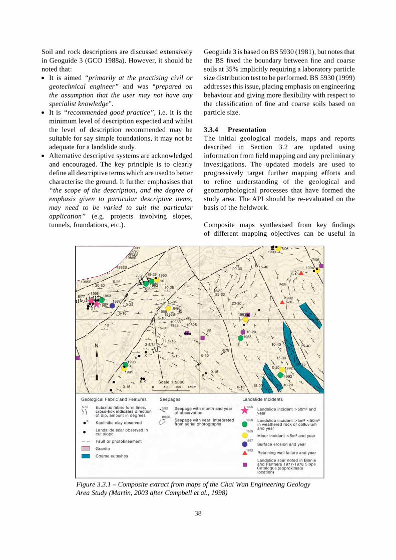
Soil and rock descriptions are discussed extensively in Geoguide 3 (GCO 1988a). However, it should be noted that: • It is aimed “primarily at the practising civil or
geotechnical engineer” and was “prepared on the assumption that the user may not have any specialist knowledge”.
• It is “recommended good practice”, i.e. it is the minimum level of description expected and whilst the level of description recommended may be suitable for say simple foundations, it may not be adequate for a landslide study.
• Alternative descriptive systems are acknowledged and encouraged. The key principle is to clearly define all descriptive terms which are used to better characterise the ground. It further emphasises that “the scope of the description, and the degree of emphasis given to particular descriptive items, may need to be varied to suit the particular application” (e.g. projects involving slopes, tunnels, foundations, etc.).
Geoguide 3 is based on BS 5930 (1981), but notes that the BS fixed the boundary between fine and coarse soils at 35% implicitly requiring a laboratory particle size distribution test to be performed. BS 5930 (1999) addresses this issue, placing emphasis on engineering behaviour and giving more flexibility with respect to the classifi cation of fine and coarse soils based on particle size.
3.3.4 Presentation The initial geological models, maps and reports described in Section 3.2 are updated using information from field mapping and any preliminary investigations. The updated models are used to progressively target further mapping efforts and to refine understanding of the geological and geomorphological processes that have formed the study area. The API should be re-evaluated on the basis of the fieldwork.
Composite maps synthesised from key findings of different mapping objectives can be useful in
SlopeCatalogue
Figure 3.3.1 – Composite extract from maps of the Chai Wan Engineering Geology Area Study (Martin, 2003 after Campbell et al., 1998)
38

D
DDD
D
D
D
DD
DDD
D
D
DD
D
D
D
D
DD
D
DD
D
D
D
D
DDDD
DDD
D
SD
D
D
D
DDD
D
DD
DD
D
D
D
DD
D
D
D
DD
D
D
D
D
D
D
D
D
D
D DD
D
D
D
DDDD
D
D DD
D D
REGIONAL CROSS-FAULTS D
ROUTE 3 TLT
D
D D
DDDDD DD
D DD DD
D
D
D D D DD
DD
D D
DD D
D
D
D
D
D
D
D
D
TSING LUNG TAU FAULT
SIU LAM FAULT
SHAM TSENG FAULT
WEST WSD TUNNEL
SO KWUN WAT FAULT MAX. HORIZONTAL
STRESS DIRECTION DDD D
D
D D D
D D D
D D D
D D
D D D D D
D D
D D D
D
D D
D
D D D
C D D D
D D DD
D D C D
D D
D D CDC
D D
D D DD
D D
D
D D
DDDD
D D
D
DD
D
D
D D
D D DD D
D D D
DD
D
D D
DD
DD
D D
D
D
D
D
DDD D D D
D
D
D
DD
D D D D
D
D - Joint C - Shear
D D D D D D S - Shatter Zone D
EQUAL AREA LOWER HEMISPHERE STEREOGRAPHIC PROJECTION
Figure 3.3.2 – Example of a structural domain summary plot for the Route 3 Tai Lam Tunnel
building-up an overall appreciation of the geological constraints present within a site. Figure 3.3.1 shows a composite map synthesised from separate maps of geological fabric and features, seepages and landslide incidents.
Figure 3.3.2 shows an example of a summary stereoplot for a structural domain in close proximity to the south portal of the Route 3 Tai Lam Tunnel which, in addition to providing discontinuity information, includes the main regional fault trends and in situ stress direction in relation to the tunnel alignment. Such maps and orientation diagrams are useful for displaying the potential structural geological controls on the stability of a site to the design team.
For projects that are potentially vulnerable to geological hazards, it may be beneficial to generate geological uncertainty schedules and maps. These can be audited, traced and updated as the site investigation and creation of the ground model progresses. Appropriate descriptions of key engineering geological issues such as existing
instabilities, adverse geological structure, kaolininfilled discontinuities, irregular rockhead profile and perched or high groundwater tables should be made.
Different geological models depicting plausible ranges of ground conditions can be developed to plan the ground investigation and aid communication among members of the design team.
3.4 SUB-SURFACE EXPLORATION
3.4.1 Introduction Depending on the level of geological and geotechnical uncertainty, and the type and scale of the proposed works, ground investigations are usually required to further refine the geological and/or ground models for design purposes. Where time, access and environmental constraints allow, a staged approach to ground investigations is normally the most effective, with the initial investigation primarily focused on testing the geological model and the resolution of geological and hydrogeological uncertainty.
39
This allows the sub-surface materials, geological structures and hydrogeological regimes to be better defined in three dimensions which facilitates the planning of more detailed investigations primarily aimed at determining engineering parameters for ground and groundwater modelling and excavatability assessments.
3.4.2 Existing Guidance Key guidance on site investigations is contained in GCO (1987b). Other relevant documents include: • AGS-HK (2004a,b,c,d,e; 2005a,b) Ground
Investigation Guidelines. • Geospec 3 (GEO, 2001). • BS5930 (BSI, 1999) gives international guidance. • International Society for Rock Mechanics and
American Society for Testing and Materials standards for rock testing.
• Ground Investigation Working Party Final Report, (IMMM-HK, 2003).
• GEO (2005a) for site investigations for tunnel works.
Sections 6.8, 6.9 and 6.10 of this document refer to site investigation for reclamations, contaminated land and landfills, and natural resources respectively.
3.4.3 Ground Investigation
General The ground investigation needs to verify the geological and hydrogeological conditions, address areas of uncertainty and identify features which are of particular relevance to the stability or performance of the proposed works and its surroundings (see Figure 4.4.9 for an example). The types and methods of investigation will depend on the anticipated geology, local constraints, environmental considerations and the nature of the proposed works.
Geophysical Methods Where the terrain and site conditions are suitable, geophysical surveys can be cost-effective in covering large areas in a relatively short time, particularly for offshore locations (see Sections 6.8 and 6.10) and also for onshore terrain which may be blanketed by thick regolith with few outcrops. However, problems can occur due to interference that makes it diffi cult to differentiate true signals from noise.
Typical geophysical methods for engineering
geological application include gravity, magnetic, seismic reflection, seismic refraction and resistivity surveys. A large amount of geophysical data for the offshore areas of Hong Kong is held by the Hong Kong Geological Survey (HKGS) of GEO. Fyfe et al. (2000) show examples of the use and interpretation of seismic surveys for offshore areas in Hong Kong. Evans et al. (1995) provide guidance on the interpretation of seismic refl ection surveys. The geological model should form the basis for the type and location of the surveys undertaken. For example, survey lines orientated perpendicular to known features such as infilled channels allow better resolution.
Examples of the use of gravity surveys to identify areas of deep weathering associated with karst areas and major faulting can be found in Collar et al. (1990) and Kirk et al. (2000) respectively. Collar et al. (2000) discuss the adaptation and limitations of gravity surveys to steeply sloping terrain, and indicate that where appropriate environmental adjustments are made, the method could prove to be useful in formulating preliminary rockhead models to aid the planning of further investigations (Figure 3.4.1).
GEO (2004h) contains reviews of the use of down-hole geophysical methods such as gamma density and spectral gamma to detect clay-rich seams in saprolite and rock.
As with any indirect method of investigation, considerable knowledge and skill are required in order to effectively specify and plan the investigation and interpret the results. Direct investigations are also necessary in order to calibrate and verify the model developed from geophysical data.
Direct Methods Direct investigations may include drillholes, trial pits, trenches and slope stripping. GCO (1987b) provides guidance of a general nature on site investigation and sampling quality class. However, more detailed investigation may be necessary where the findings of the initial geological model indicate the possible presence of important geotechnical conditions (e.g. clusters of previous failures, heavy seepage, voids, soil pipes, deep weathering, etc.).
In order to maximize the information obtained, the ground investigation should be planned around the relevant aspects of the initial geological model
40
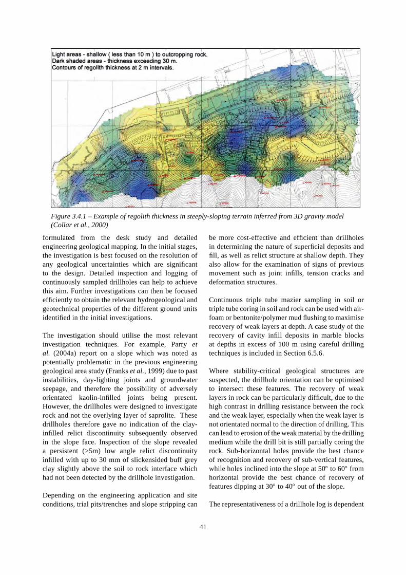
Figure 3.4.1 – Example of regolith thickness in steeply-sloping terrain inferred from 3D gravity model (Collar et al., 2000)
formulated from the desk study and detailed engineering geological mapping. In the initial stages, the investigation is best focused on the resolution of any geological uncertainties which are significant to the design. Detailed inspection and logging of continuously sampled drillholes can help to achieve this aim. Further investigations can then be focused efficiently to obtain the relevant hydrogeological and geotechnical properties of the different ground units identified in the initial investigations.
The investigation should utilise the most relevant investigation techniques. For example, Parry et al. (2004a) report on a slope which was noted as potentially problematic in the previous engineering geological area study (Franks et al., 1999) due to past instabilities, day-lighting joints and groundwater seepage, and therefore the possibility of adversely orientated kaolin-infilled joints being present. However, the drillholes were designed to investigate rock and not the overlying layer of saprolite. These drillholes therefore gave no indication of the clayinfilled relict discontinuity subsequently observed in the slope face. Inspection of the slope revealed a persistent (>5m) low angle relict discontinuity infilled with up to 30 mm of slickensided buff grey clay slightly above the soil to rock interface which had not been detected by the drillhole investigation.
Depending on the engineering application and site conditions, trial pits/trenches and slope stripping can
be more cost-effective and efficient than drillholes in determining the nature of superficial deposits and fi ll, as well as relict structure at shallow depth. They also allow for the examination of signs of previous movement such as joint infills, tension cracks and deformation structures.
Continuous triple tube mazier sampling in soil or triple tube coring in soil and rock can be used with air-foam or bentonite/polymer mud flushing to maximise recovery of weak layers at depth. A case study of the recovery of cavity infill deposits in marble blocks at depths in excess of 100 m using careful drilling techniques is included in Section 6.5.6.
Where stability-critical geological structures are suspected, the drillhole orientation can be optimised to intersect these features. The recovery of weak layers in rock can be particularly difficult, due to the high contrast in drilling resistance between the rock and the weak layer, especially when the weak layer is not orientated normal to the direction of drilling. This can lead to erosion of the weak material by the drilling medium while the drill bit is still partially coring the rock. Sub-horizontal holes provide the best chance of recognition and recovery of sub-vertical features, while holes inclined into the slope at 50° to 60° from horizontal provide the best chance of recovery of features dipping at 30° to 40° out of the slope.
The representativeness of a drillhole log is dependent
41

on the continuity and quality of the samples available for logging. The standard ground investigation sampling of alternating mazier samples and standard penetration test (SPT) liner samples, will result in only 5% of the ground investigated being available for inspection from the cutting shoes. In order to achieve a more continuous record, any mazier samples and SPT liner samples that will not be used for testing should be opened, logged in detail and photographed. Particular attention should be paid to discontinuities and weak layers (such as shear zones and more weathered zones, see the South Bay Close example in Section 6.4.4).
Drillholes and trial pits in Hong Kong are typically logged by personnel who may not have been informed of the purpose of the investigation and the details of the geological model. Figure 3.4.2 compares a trial pit log prepared without the benefit of a geolgical model (Log ‘a’) with that produced in the context of the geological model and purpose of the investigation (Log ‘b’). This demonstrates the need for good communication between the designer and the ground investigation contractor.
The orientation of discontinuities in rock drillholes can be assessed using impression packers, televiewers, mechanical core orientation methods, etc. The relative orientations of the drillholes and the discontinuity sets must be known in order to assess the true spacing of each set. If outcrops are available, mapping of discontinuities should be used to provide a better understanding of the geological structure and to provide a check on possible errors in core orientation. Figure 3.4.3(a) shows a plot of joint orientations as initially recorded on the logs for an inclined drillhole. Discontinuity data from mapping of outcrops and from other orientated drillholes indicated a consistent structural pattern in the area which was markedly different from the drillhole data. It was realised that the reference line on the drillhole had been erroneously rotated by 180°. Figure 3.4.3(b) shows the corrected plot for comparison.
A major limitation of measurement of discontinuities in drillholes is that no indication can be obtained of the relative persistence of discontinuity sets. Figure 3.4.4(a) shows a stereoplot of mapping data from a quarry face where discontinuities
Landslide Debris Old Colluvium (clayey silt)
Completely Decomposed Andesite
Highly Decomposed Andesite
Shear Surfaces
Colluvium
Colluvium (clayey silt)
Completely
Tension Crack
(clayey silt with some gravel cobbles & boulders)
(clayey sand with much gravel cobbles & boulders)
Decomposed Tuff Log ‘a’
Log ‘b’
Figure 3.4.2 – Comparison of two logs for the same trial pit (after Parry & Campbell, 2003)
42

‘Daylight envelope
Figure 3.4.3 – Comparison of as-reported and as-corrected stereoplots of joint data for the same inclined drillhole core
(a) - As-reported (b) - As-corrected
(reference line rotated around core by 180°)
‘Daylight’ envelope
with a persistence of less than 3 m were ignored. Figure 3.4.4(b) shows discontinuity data obtained from orientated acoustic televiewer logging of drillholes in the same quarry. The apparent
difference in the relative orientation and the significance of ‘Set 5’ in each plot is primarily due to the impersistence of that particular set.
(a) - Quarry face mapping data for joints greater than 3 m in persistence (b) - Acoustic televiewer drillhole data
Apparent joint set no. 5 (inferred to be of limited persistence)
Figure 3.4.4 – Comparison of mapping data and acoustic televiewer data for the same quarry
43
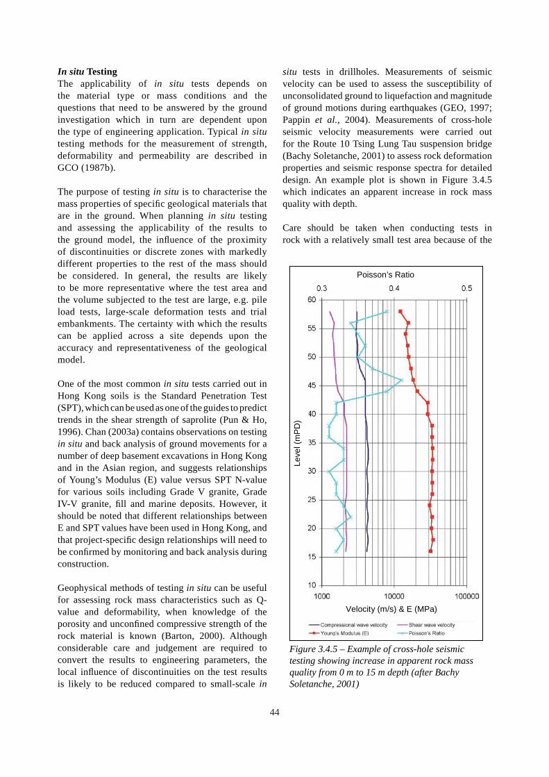
In situ Testing The applicability of in situ tests depends on the material type or mass conditions and the questions that need to be answered by the ground investigation which in turn are dependent upon the type of engineering application. Typical in situ testing methods for the measurement of strength, deformability and permeability are described in GCO (1987b).
The purpose of testing in situ is to characterise the mass properties of specific geological materials that are in the ground. When planning in situ testing and assessing the applicability of the results to the ground model, the influence of the proximity of discontinuities or discrete zones with markedly different properties to the rest of the mass should be considered. In general, the results are likely to be more representative where the test area and the volume subjected to the test are large, e.g. pile load tests, large-scale deformation tests and trial embankments. The certainty with which the results can be applied across a site depends upon the accuracy and representativeness of the geological model.
One of the most common in situ tests carried out in Hong Kong soils is the Standard Penetration Test (SPT), which can be used as one of the guides to predict trends in the shear strength of saprolite (Pun & Ho, 1996). Chan (2003a) contains observations on testing in situ and back analysis of ground movements for a number of deep basement excavations in Hong Kong and in the Asian region, and suggests relationships of Young’s Modulus (E) value versus SPT N-value for various soils including Grade V granite, Grade IV-V granite, fill and marine deposits. However, it should be noted that different relationships between E and SPT values have been used in Hong Kong, and that project-specific design relationships will need to be confirmed by monitoring and back analysis during construction.
Geophysical methods of testing in situ can be useful for assessing rock mass characteristics such as Q-value and deformability, when knowledge of the porosity and unconfined compressive strength of the rock material is known (Barton, 2000). Although considerable care and judgement are required to convert the results to engineering parameters, the local influence of discontinuities on the test results is likely to be reduced compared to small-scale in
situ tests in drillholes. Measurements of seismic velocity can be used to assess the susceptibility of unconsolidated ground to liquefaction and magnitude of ground motions during earthquakes (GEO, 1997; Pappin et al., 2004). Measurements of cross-hole seismic velocity measurements were carried out for the Route 10 Tsing Lung Tau suspension bridge (Bachy Soletanche, 2001) to assess rock deformation properties and seismic response spectra for detailed design. An example plot is shown in Figure 3.4.5 which indicates an apparent increase in rock mass quality with depth.
Care should be taken when conducting tests in rock with a relatively small test area because of the
Poisson’s Ratio
Velocity (m/s) & E (MPa)
Leve
l (m
PD
)
Figure 3.4.5 – Example of cross-hole seismic testing showing increase in apparent rock mass quality from 0 m to 15 m depth (after Bachy Soletanche, 2001)
44

diverse results depending on the local infl uence of discontinuities. For instance, whereas pump tests from wells can determine the mass hydraulic properties of a rock aquifer, packer tests over short lengths of drillholes can yield considerably variable results. For similar reasons, the hydraulic fracturing method of in situ stress measurement in rock generally gives less scatter than the over-coring method which is more sensitive to the presence of discontinuities near the strain gauges (Free et al., 2000).
3.4.4 Hydrogeological Investigation The potential variability of hydrogeological regimes, as outlined in Sections 4.6, 6.4 and 6.7 needs to be incorporated into the geological model to enable the planning of an effective hydrogeological investigation. Interpretation of groundwater regimes is generally based on regular monitoring, preferably throughout at least one wet season, for land-based projects. Groundwater monitoring may need to be continued throughout the construction and post-construction phases to gauge the possible effects due to the works.
The location of the response lengths and the number of piezometers should be optimised with reference to the geological model to ensure that all hydrogeologically significant zones and boundaries are adequately monitored. During drilling of holes for piezometers, detailed logging on site provides more information that can be used to refine the geological model and to optimise the locations and the response lengths. Typical locations for piezometers and tests, which may need to be considered, include: • Upslope and downslope of steeply inclined
geological features which may act as aquitards. • Within discontinuities (potential high cleft-water
pressure during rainstorms). • Within permeable zones in the weathering profile,
which may include Grade III/IV materials (perched or confi ned groundwater).
• Directly above low-angle clay-infilled discontinuities (potential perching).
• Above the rock to soil interface (potential perching).
• Below the rock to soil interface (potential confined groundwater).
• At soil pipes or zones showing evidence of groundwater flow (potential high response during rainstorms).
• Above the saprolite/superficial deposit interface (potential perching).
• Within any coarse layers in superfi cial deposits or fill (potential perching and/or potentially high response during rainstorms).
Given the above, the use of standpipes with long response zones which intersect a number of the features noted above makes interpretation of the data problematic.
Where significant seepage is noted, groundwater tracer tests may be conducted by introducing dyed or chemically identified water into the piezometer and monitoring the seepage points to detect resurgence (GCO, 1982; Nash & Chang, 1987).
The optimisation of hydrogeological investigations depends to a great extent on the progressive development of the geological model during the investigation to enable variations to be made with regard to depth and number of piezometers, the number, location and orientation of drillholes and also the frequency and period of monitoring.
For slope stability assessments, monitoring of groundwater levels using electronic transducers and data loggers provides information on rapid groundwater responses to individual rainstorms. In some less critical situations the installation of ‘Halcrow buckets’ in piezometer tubing is a cost-effective alternative which can indicate the highest water level reached between observations with an accuracy equal to the spacing of the buckets.
Where access is difficult, piezometers may be located in trial pits, although care must be taken to minimise the effects of disturbance (MFJV, 2004), or in holes bored with a lightweight portable drilling rig (Chau & Tam, 2003). Examples of detailed hydrogeological studies using a variety of techniques are documented in GCO (1982), Weeks & Starzewski (1985), Evans & Lam (2003a,b), and MFJV (2004).
For detailed studies, continuous monitoring of site-specific rain gauges, surface water weirs and groundwater drain flows (Section 4.6) may be required. This allows groundwater responses, and hence the effectiveness of drainage works, to be assessed in relation to specific rainstorms and antecedent rainfall patterns. In these cases, it may be beneficial to carry out real-time monitoring with all instrumentation having the capability of being remotely sampled and transmitted to the office
45

for processing. A review of slope instrumentation practice in Hong Kong and its development trends is given in Wong et al. (2006).
3.4.5 Storage and Handling of Data For large projects, it is common to use geotechnical database management software to store and analyse data from ground investigations with data coded in standard AGS format or variants thereof (AGS, 1999). An example is the data management system used for the Chek Lap Kok Airport (Plant et al., 1998).
However, it is important that all relevant geological materials and features are properly identified, characterised and coded in such a way that the data can be easily verified, retrieved and manipulated to facilitate further development of the geological model. The parallel maintenance of hand-drawn models which depict the geology and hydrogeology in 3-dimensions can provide the necessary verification of any computer generated diagrams and can often be more cost-effective in providing an overall understanding of the site.
3.4.6 Updating the Geological Model After each stage of ground investigation work, the data needs to be critically reviewed and incorporated into the geological model for the project. This enables refinement of the model to be carried out and also provides a check for ground investigation data that may be inconsistent with the overall model. Such anomalies may be due to inconsistent logging or interpretation of materials. Alternatively, the anomalies may indicate that the geological model needs to be adjusted or that areas of uncertainty exist which may need further investigation if they are judged to be sufficiently critical to the proposed works. These may need to be noted for auditing and tracing by the design team throughout the rest of the investigation and design process.
3.5 GEOTECHNICAL CHARACTERISATION
3.5.1 Introduction This section outlines the main engineering geological considerations for the evaluation and assessment of data to select appropriate parameters or range of parameters for development of the ground model.
The data from the ground investigations will be used
to determine possible ranges of material properties and mass properties, including environmental factors such as the groundwater regime, contamination and in situ stress conditions. Estimates of the possible ground and groundwater responses to changes in environmental conditions during construction and over the design life of the proposed works may also be necessary in order to define the spatial extent of any further ground investigation and monitoring requirements.
The main engineering geological inputs to the development of the ground model include: • identification of any stability-critical
discontinuities, zones of weakness or permeability contrasts that may need to be considered in the ground and design models,
• selection of samples for testing with reference to the engineering geological zoning of the site,
• assessment of empirically derived geotechnical parameters based on detailed observations of rock mass characteristics,
• assessment of the spatial variability of the ground based on correlation of the test data with the geological model to minimise inappropriate spatial averaging of data from different materials and masses, and
• revision of the geological and ground models as more data is received.
The methods of ground investigation, testing and instrumentation which can be used to facilitate geotechnical characterisation of the ground (see Section 3.4) will depend on the geological model, the proposed works and the intended design methodologies. As such, the degree of engineering geological input will vary. For instance, projects that involve large excavations in rock or mixed rock and soil profiles need a relatively high level of engineering geological input because the engineering performance of the works is likely to be controlled by discontinuities, variations in hydrogeology and variations in weathering that affect mass stability. By comparison, for small-scale excavations, after it has been determined that the geological and hydrogeological variability of the site is relatively minor, less engineering geological input is needed.
Engineering geological issues that affect the material and mass properties of the main rocks and soils of Hong Kong are further discussed in Chapters 4 and 5.
46

3.5.2 Material Properties Material properties can be obtained by conducting tests in a laboratory on small samples. GCO (1987b) and GEO (2001) contain detailed descriptions and specifications of types of laboratory tests for soils, rocks and groundwater.
The representativeness of test results can be affected by variations in lithology, material type and fabric, bias in selection of samples, size of sample, presence of discontinuities and test procedures. In addition, weaker rocks and soils can be affected by sample disturbance and the scale effects of large inclusions. The representativeness of laboratory test data with respect to preparation of samples and the appearance of samples after testing should be critically reviewed before the data is incorporated into the ground model. Even the presence of microscopic flaws in apparently intact samples can reduce test values with increasing size of sample (Figure 3.5.1).
In view of the typically small volume of material tested relative to the volume and variability of mass affected by the proposed engineering works, it is good practice to assess the results and their applicability based on an engineering geological knowledge of the materials and their spatial distribution within the site. Correct identification of the material being tested also facilitates the grouping of test results to derive realistic ranges of engineering properties for
Figure 3.5.1 – Influence of specimen size on strength of ‘intact’ rock (Hoek, 2000)
application within the ground model.
Testing in situ is outlined in Section 3.4.3. Determination of material properties from in situ tests requires interpretation. Detailed knowledge of the geology and weathering profile, and trends in and established relationships between shear strength, decomposition, micro-fracturing, grading and moisture content, together with in situ test values can be used to determine realistic ranges of material properties for the different zones within a site (Martin, 2003).
3.5.3 Properties of Discontinuities
Laboratory Testing Tests on small samples in a laboratory require interpretation. For example, when testing discontinuities in rock under direct shear, small scale asperities can greatly affect the measured angle of friction (Richards & Cowland, 1982). As the shear strength envelope of naturally rough discontinuities is strongly curved, it is also important to ensure that the range of normal stress during testing is of a similar order to the range of normal stress expected under field conditions. Furthermore, direct shear tests can be affected by misalignment of the shear box with the plane being tested (Campbell & Parry, 2002). Kulhawy & Goodman (1980) and ISRM (1981) provide information on the laboratory measurement of the shear stiffness of rock joints.
Field-scale Estimation of Discontinuity Shear Strength The assessment of discontinuity shear strength at a scale relevant to the proposed works can be carried out using large-scale in situ shear tests. However, these are expensive and can be difficult to control or to accurately measure the forces during testing. For these reasons, recourse is often made to indirect methods of shear strength estimation, based on a basic friction angle, say as derived from laboratory tests. In addition, in situ factors such as surface roughness and irregularity, type and thickness of infi ll material and the strength of any asperities, which influence shearing resistance, need to be considered.
Guidelines for the description of surface roughness and irregularity are contained in GCO (1988a), and methods of assessing field-scale shear strength are summarised in Hoek (2000). This latter work draws on key references such as Barton & Choubey
47

(1977), Richards & Cowland (1982) and Hencher & Richards (1982). The reduction in the effect of small-scale asperities with increasing length of discontinuity is addressed by Barton & Bandis (1990) and Barton (1990). Where discontinuities contain infills, shearing may occur at the interface between the infill and the wall of the discontinuity. Such planes can exhibit much lower shear strength than that of intact infill material (Deere & Patton, 1971).
3.5.4 Mass Properties
General The mass properties of weathered rocks are governed by the properties of the constituent materials and of the discontinuities therein. In some cases, the properties of the materials may dominate the overall behaviour of the ground mass. Coarse-grained igneous rocks with widely-spaced joints may give rise to corestones upon weathering (see Section 4.4.4). The effect of the presence of corestones on the mass properties of the soil has been studied (Irfan & Tang, 1993).
The properties of the discontinuities are more likely to dominate mass behaviour where the discontinuities have relatively low shear strength, are relatively closely spaced, relatively extensive and unfavourably orientated with respect to potential ground deformations or stability. Where a single discontinuity or a combination of discontinuities occurs which may cause direct sliding, the properties of the specific discontinuities are of far more concern than the mass properties.
Given the dominant role of discontinuities in affecting the geotechnical properties of weathered rock masses, this section primarily concentrates on the types of models and methods of classification that may be used to characterise the effect of discontinuities on the mass properties of the ground.
Owing to the uncertainties involved in assessing the properties of ground masses, it is good practice to derive a range of potential mass parameters that reflect these uncertainties for use in sensitivity analyses.
Intact rock specimens
One joint set
Two joint sets
Many joints
Heavily jointed rock mass
Figure 3.5.5.2 – Scale effect on the characteristics of discontinuous rock masses .(Hoek, 2000)
48

Figure 3.5.3 – Candidate failure surface involving a number of different shear failure mechanisms (Hoek et al., 2000)
Effect of Discontinuities on the Mass Properties of Weathered Rocks The mass shear strength and stiffness of weathered rocks are generally lower than the values indicated from laboratory tests on material samples, due to the presence of discontinuities (Figure 3.5.2). For example, Figure 3.5.3 illustrates some of the failure modes that may need to be considered in slope stability analysis. These may involve shear along a through-going major weakness, shear through the mass weakened by second order discontinuities and shear along stepped paths created by two or more discontinuity sets. The presence of steeply inclined, critically orientated discontinuities within the potential sliding mass may be an important factor that influences stability and the consequent brittleness and potential mobility of the mass at failure (Figure 3.5.4).
Figure 3.5.4 – Typical internal shears required to permit movement in a non-circular slide (Hutchinson, 1987)
bounding slip surface
internal shears
graben forms here
tension crack
G.L.
The anisotropic effect of discontinuities on the mass shear strength of saprolite has been modelled using probabilistic methods (e.g. Koo, 1982), but these are difficult to apply in practice. Knowledge of past failures in similar ground conditions combined with a detailed knowledge of the engineering geology of the site can assist in determining the site-specific applicability of such models (Wong & Ho, 2000a).
An example of an alternative approach is given in Section 6.4.4 for the Ting Kau Cutting where a range of scenarios were incorporated into the ground model for sensitivity analysis. Different ranges of mass shear strength and discontinuity orientation, continuity, spacing, and location relative to the excavation were modelled based on the structural data from field investigations conducted for initial design, supplemented by detailed mapping of the excavation during construction.
GCO (1984), Hencher (1985) and GEO (2004c) contain guidance on the uses and limitations of stereographic projections and the influence of major discontinuities on the mass stability of rock slopes. Important considerations include: • the recognition and presentation on stereoplots of
single, through-going planes of weakness, • the influence of discontinuities at a low angle with
low strength (e.g. Fei Tsui Road – GEO, 1996a,b; Shek Kip Mei – FMSW 2000),
• the effect on mass stability of non-daylighting
49

discontinuities, and • the role of groundwater in reducing the operative
friction angle when considering the use of friction cones on stereonets to assist in the assessment of kinematic admissibility for failure.
Empirical Methods of Characterisation of Rock Masses Empirical methods of rock mass classifi cation are based largely on the spacing and condition of the discontinuities, and, in most cases, on the unconfined compressive strength (UCS) of the material. These classification systems do not give engineering parameters directly, and considerable experience and judgement are required in order to derive an appropriate range of parameters.
A listing of some rock mass classifi cation systems that are commonly used in Hong Kong is given below. Their main uses, input parameters and key references are also cited.
• Rock Mass Rating (RMR) System – (Bieniawski, 1989) o Uses – Rock mass classification system for
design of support systems for underground excavation and for estimating rippability and dredgeability. Modified forms can also be used to provide estimates of rock mass deformability (GEO, 2006).
o Main Input Parameters – UCS, Rock Quality Designation (RQD), discontinuity spacing, discontinuity condition, groundwater rating and discontinuity orientation rating.
• Q System – (Grimstad & Barton, 1993) o Uses – Rock mass classification system for
design of underground excavation support systems. Also used for assessing TBM suitability. Modified forms can be used to provide estimates of rock mass deformability (Hoek et al., 1995; Hoek, 2000, 2004; Barton, 2000).
o Main Input Parameters – RQD, discontinuity set rating, discontinuity conditions, groundwater rating and stress reduction factor.
• Geological Strength Index (GSI) and Hoek/Brown Strength Criterion – (Hoek, 2000; Marinos & Hoek, 2000; Hoek, 2004; RocLab, 2004) o Uses – Rock mass classification system
to derive estimates of deformability and
Hoek/Brown non-linear strength parameters for the analysis of slopes, foundations and underground excavations.
o Main Input Parameters for GSI – Rock type, rock structure/degree of interlocking of rock pieces, discontinuity condition.
o Main Input Parameters for Deformation Modulus – GSI and UCS.
o Main Input Parameters for Hoek/Brown Strength Criterion – rock type GSI, UCS and excavation disturbance factor.
• IMS System – (McFeat Smith, 1986) o Uses – Rock mass classification system for
design of underground excavation support systems and for estimating performance of Tunnel Boring Machines (TBM).
o Main Input Parameters – Weathering grade, spacing and orientation of discontinuities, and conditions of water infl ow.
• MQD Karst Classification – (Chan, 1994; Chan & Pun, 1994) o Use – Classification of buried karst from
drillhole data to facilitate identifi cation of the extent of marble slightly affected and unaffected by dissolution. Used for zoning marble rock masses for estimating suitability for foundations in Scheduled Areas 2 and 4 in Hong Kong.
o Main Input Parameters – RQD and percentage core recovery (see Section 5.5).
Considerable uncertainty in the resulting engineering parameters is likely to exist due to the indirect nature of classification systems. For this reason, a wide range of values may need to be considered for sensitivity analyses. An example of the translation of engineering geological data into a range of engineering parameters for sensitivity analysis using the Q-system and GSI-system is shown in the KCRC Tai Lam Tunnel example in Section 6.7.4. This example also illustrates the sensitivity of the possible range of ground deformations to the engineering geological characterisation of the rock mass.
3.5.5 Characterisation of Hydrogeological Properties
After completion of the main ground investigation works, a range of tested permeabilities will have been obtained, and actual or potential high permeability zones will have been identifi ed. As monitoring
50

continues, further piezometer readings and rainfall data will become available. In many applications further characterisation of hydrogeological properties can be achieved by monitoring the subsequent groundwater response and by back analysis. This allows further development of the geological model and refinement of the values assigned to the hydrogeological properties (see Section 4.6).
3.6 MODEL DEVELOPMENT DURING DESIGN AND CONSTRUCTION
3.6.1 Development During Design In selecting the initial design methodology, judgement is required to assess the degree of adversity of the geotechnical conditions (Martin, 2003). This can be facilitated by consideration of the sensitivity of the proposed works to the range of possible conditions and potential mechanisms of deformation or shear failure indicated by the ground model. For example, in critical cases, appropriate numerical models or the Sarma limit equilibrium method (Sarma, 1979) may be used to assess the mass stability of jointed rocks or saprolite (Hoek et al, 2000; Tattersall, 2006). The application of such methods can give insight into the uncertainties of the effect of internal shear planes or release surfaces on the operational mass shear strength, failure mode and safety margin of jointed slopes that cannot be accommodated by the other more commonly used methods of limit equilibrium analysis.
3.6.2 Verification During Construction Development and verification of the design should continue during construction when the ground is exposed and when it is subjected to temporary and permanent changes in loadings and changes in hydrogeological conditions. Depending on the nature of the works, engineering geological input can assist in the verification and updating of the geological, ground and design models. Typical tasks include the recording and reporting of exposed ground conditions, carrying out additional investigations and interpreting responses of the ground and of the groundwater in an engineering geological context.
Existing guidance and standards pertaining to the verification of design assumptions during construction works in Hong Kong are listed below: • PNAPs 74, 83, 85, 161 and 274 - (BD, 1993, 1994,
1997, 1998, 2003) • BD (2004a) • TGNs 2, 4, 10, 11, 14 & 16 - (GEO,
2004b,c,d,e,i,j) • Geotechnical Manual for Slopes - (GCO, 1984) • Geoguide 2 - (GCO, 1987b) • Highway Slope Manual - (GEO, 2000)
Much of the guidance contained in GEO (2004c) for rock slopes is equally applicable to saprolite slopes. During construction there are usually ample opportunities to map exposures in temporary excavations and on slopes before surfacing.
The value of engineering geological input during construction works for different types of engineering application is further discussed in Chapter 6.
51
4. GEOLOGICAL PROCESSES AND ENGINEERING IMPLICATIONS
4.1 INTRODUCTION This chapter provides a brief introduction to the key geological processes that affect the engineering characteristics of most rocks and superfi cial deposits in Hong Kong, i.e. processes that are not limited to any one stratigraphical or lithological unit. These processes include: • tectonics, • metamorphism and hydrothermal alteration, • weathering, • geomorphological processes, and • hydrogeological processes.
Understanding these processes, their evolution over geological time, their spatial relationships and their effect on the engineering properties of different lithological units (Chapter 5) is key to the development of geological models for engineering purposes.
4.2 TECTONICS AND TECTONIC STRUCTURES
4.2.1 Introduction The solid geology of Hong Kong and the current seismic and in situ stress regimes are a result of plate tectonics. The current plate margin lies to the southeast of Hong Kong running from Taiwan to the Philippines. However, during the late Jurassic and early Cretaceous Periods the plate margin was much closer to Hong Kong (Sewell et al., 2000). This resulted in a period of intense volcanic activity with associated granitic intrusions, and also in the main pattern of faults evident today (Figure 4.2.1).
Tectonic structures include faults, folds, metamorphic fabrics such as foliation and cleavage, and tectonic joints. These structures reflect the response of the rock mass to in situ stress over geological time. Most faults, metamorphic fabrics and joints are discontinuities that have much lower strength than the intact material. In the case of faults and joints that are not healed by mineralisation, the tensile strength is effectively zero. Therefore, discontinuities have a major effect on the engineering properties of rock masses.
Key engineering geological issues include: • the effect of past and present regional tectonic
settings on the formation of geological structures and in situ stress,
• zones of deep weathering along some of the major faults and their engineering implications,
• the geotechnical influences of different types of faults,
• the development and significance of discontinuities, including the response to stress-relief from natural and man-made sources, and
• preferential groundwater fl ow.
A summary of types, occurrence and geotechnical significance of discontinuities, including those that are not of tectonic origin, is given in Hencher (2000). Further information on the characteristics of discontinuities associated with common rock types in Hong Kong is contained in Chapters 5 and 6.
4.2.2 Faults Faults can adversely affect engineering works and need to be identified and characterised during site investigations and catered for during the detailed geotechnical design. Faults are often more deeply weathered than the surrounding rocks and may contain hydrothermally altered and sheared, relatively weak material at great depth. In addition, the tectonic movements which cause brittle faulting may increase the intensity of jointing and the hydraulic conductivity of the rock mass for considerable distances on either side of a fault (i.e. brittle tectonised rock masses). The effect of faults depends on their genesis and type (e.g. high pressure ductile, low pressure brittle, or multiple ductile and brittle type movements which have affected the same fault at different times and depths). Knowledge of the overall tectonic setting facilitates the anticipation and investigation of fault-related features.
The general pattern of the main known and inferred faults is shown in Figure 4.2.1. In most instances faults are poorly exposed and obscured by superficial deposits. Minor faults with displacements of a few metres or less are commonly observed in excavations and can be traced for several metres or sometimes tens of metres. Major faults, inferred to extend for distances varying from hundreds of metres up to tens of kilometres are less commonly exposed in excavations. Consequently, there are few detailed descriptions of the major fault zones in Hong Kong (Sewell et al., 2000).
Some of the limitations of the published geological maps are discussed in Sections 3.2 and 6.7.
52
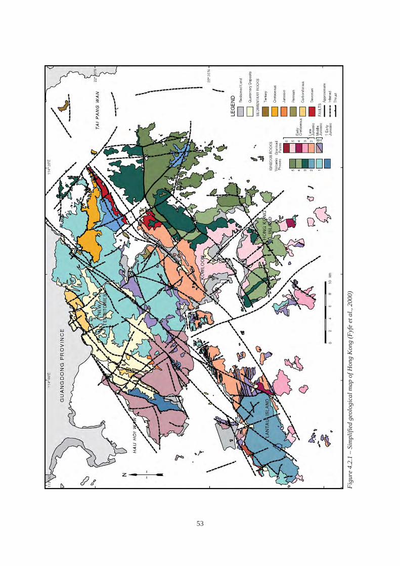
Figu
re 4
.2.1
– S
impl
ified
geo
logi
cal m
ap o
f Hon
g K
ong
(Fyf
e et
al.,
200
0)
53

Section 6.7 gives further details and examples of the assessment and influence of faulting on major tunnelling works. These discussions and examples demonstrate that an understanding of the structural geology of the area can facilitate the effective anticipation, investigation and characterisation of fault-related structures for an engineering project.
The main faults strike northeast and can be many tens of kilometres in length. These faults strongly influence the present day topography of Hong Kong. North-striking, northwest- and north-northwest-striking faults, whilst less continuous than the northeast-striking faults, can be up to 20 km in length. East-striking faults may be up to 12 km in length, but are not regularly developed in Hong Kong.
There are many different types of faults in Hong Kong. They range from slickensided or polished, relatively unaltered discontinuities to major zones of broken and sheared rock which are susceptible to weathering, and may form distinct, linear depressions in the topography. However, some faulted zones have been partially silicified by hydrothermal fluids and as a result are more resistant to weathering. This may give rise to intermittent ridges along the trace of the main fault zone.
Owing to the strike-slip and multi-phase nature of most of the faults in Hong Kong, the major fault zones can be many tens of metres in width and contain a number of smaller-scale, related faults, which can be of very different orientation to the main fault zone
Figure 4.2.2 – Reidel shears within a major strike-slip fault zone (after Fookes et al., 2000 – based on Park, 1997)
σ1
σ3
1st order reidel shear
2nd order reidel shear
major strike-slip fault zone
(e.g. reidel shears - Figure 4.2.2). The discrete faults within the main zone may offset each other and form a complex arrangement of shear planes which separate relatively competent, though still partly deformed rock masses from each other (Section 6.7). The major northeast-striking fault zones are also commonly offset by northwest- and north-striking faults which can result in a structurally complex fault pattern.
The presence of individual faults or fault zones can be of major concern to engineering projects, due to influences on stability, deep weathering and the sharp contrast in engineering and hydrogeological properties between weak, faulted material and the host rock (see examples in Chapters 5 and 6). However, faults do not necessarily present insurmountable ground conditions if they are identified early in the project, particularly where they can be bridged by the foundations of surface structures or where ductile faults are intersected by tunnels where the potential
Figure 4.2.3 – Schematic section of a brittle-ductile fault zone (“Rambler Channel Fault”) encountered in the Harbour Area Treatment Scheme (HATS) Tunnel ‘F’ between Tsing Yi and Stonecutters Island (Sewell et al., 2000)
54

-40 mPD
-160 mPD
Figure 4.2.4 – Zone of deep weathering at Tung Chung (inferred from boreholes and gravity survey) in meta-sediment and marble xenolith-bearing granite. (Sewell & Kirk, 2000)
for sustained groundwater inflow is limited (see the KCRC Tai Lam Tunnel example in Section 6.7).
The style of deformation associated with the fault largely depends upon the depth of the fault zone at the time of movement. Mylonite and foliated zones are characteristic of ductile movement, while fault gouge, breccia and quartz stockwork/veining are characteristic of brittle movement. Reactivation of faults over geological time can result in both brittle and ductile styles now being evident (Figure 4.2.3).
The importance of distinguishing between individual features, such as zones of fault gouge and mylonite, and relatively less deformed zones composed of stronger rock fragments contained within the fault is illustrated by the KCRC Tai Lam Tunnel example in Section 6.7.
Some major fault zones are associated with dynamic metamorphism, and hydrothermal alteration may have taken place, resulting in a complex assemblage of variably altered and decomposed fault-slices. These can give rise to deep and steeply-sloping rockhead profiles (Figure 4.2.4). For instance, the existence and the full engineering implications of fault-related, deep and steeply-sloping rockhead profi les at Tung
Chung were not recognised until investigations for the development of the area were already well advanced (see Sections 5.5 and 6.5 for further details).
4.2.3 Folds and Metamorphic Structures Folding and the development of foliation and cleavage can be geotechnically significant due to the formation of additional discontinuities with preferred orientation, the development of bedding-plane shears, and small to large scale variations in geological structure across a site. Foliation may result in strength anisotropy which can give rise to difficulties regarding compliance with founding criteria for piles.
Most rocks have been tectonically deformed to some degree; however, it is most evident in the Palaeozoic sedimentary rocks (see Section 5.6). These are characterised by tight folding, and development of foliation and kink bands in argillaceous strata. An example of the control of foliation on the stability of a road cutting near Lok Ma Chau is given in Section 6.4.4.
4.2.4 In Situ Stress In situ stresses in rock arise from the tectonic setting. Figure 4.2.5 summarises the results of selected in situ
55

0
50
100
150
200
250
0 1 2 3 4 5 6
KH (SH/Sv) D
epth
(m)
Tsing Yi
Figure 4.2.5 – Maximum horizontal stress ratio KH (SH/Sv) versus depth and orientations of SH (alignment of red bars in photograph) in Hong Kong (selected data from Free et al., 2000 and Route 10 investigations)
stress measurements in Hong Kong. These show that the maximum horizontal stress (SH) in rock is more than twice the vertical stress (Sv) at depths of less than 50 m. The scatter in stress ratio and orientation of maximum horizontal stress is due to factors such as the influence of topography at relatively shallow depth, locked-in stress from different stress regimes over geological time, and proximity to major geological fabrics and structures.
Although the principal horizontal stress directions shown in Figure 4.2.5 appear to be generally consistent with regional tectonics, the strong E-W preferred orientation of maximum horizontal stress measured on Tsing Yi (Figure 4.2.5), is consistent with N-S extension locally on the NE-trending faults (Li et al., 2000) and the strong E-W-trending structure of the rock mass imparted by the intrusion of the E-W-trending dykes. When formulating geological models it is important to recognise that many different structural regimes may have existed over geological time and may have affected the directions and magnitudes of locked-in stresses.
The magnitude and direction of in situ stress can be important considerations in the design of underground structures in rock. For example, high horizontal stresses normal to the axis of a cavern or a tunnel are usually beneficial for stability of the roof while low horizontal stresses normal to a bridge anchorage can reduce the capacity of the anchorage to resist pull-out.
4.2.5 Tectonic Joints Tectonic joints are formed as a result of stress in the Earth’s crust and are common to most rock types. They often occur in distinctive sets, i.e. a series of parallel joints. The geometric relationship between sets may be interpreted with respect to a regional stress pattern or a geological structure such as a fault. However, such features may only be extrapolated with confidence where they are systematic and where the geological origin is understood. Tectonic joints may be formed under shear or tension. Joints formed under shear are commonly less rough than joints formed under tension and therefore might be expected to exhibit lower shear strengths (Hencher, 2006).
Figure 4.2.6 illustrates that similar jointing patterns in plutonic rocks can be widespread in areas of similar geology and stress-history. With appropriate knowledge of the regional geology and necessary caution, this principle can be used to formulate preliminary models of the potential structural geology of a site based on the mapping of nearby outcrops which are not necessarily within the site.
An investigation into the extent, orientation and distribution of discontinuities affecting engineering works will only be truly effective when the geological nature of the structure is taken into account. Recognition of type of discontinuity allows properties to be predicted and extrapolated with more confidence than could otherwise be justifi ed. Too
56

Sha Tau Kok Fault
Tai Lam Fault
Sham Tseng Branch Great circle for SW side of cuttings
Figure 4.2.6 – Similarity in geological structure between Tsing Lung Tau and Ting Kau shown by contoured stereoplots of mapped discontinuities (major fault strikes shown on the Tsing Lung Tau plot for reference)
often the approach to the collection and processing of data is mostly statistical with only scant regard to the geological history of the site (Hencher, 1985).
Other types of joint that can affect the rock mass include cooling joints which are discussed in Sections 5.2 and 5.4, and stress-relief joints which are discussed in Section 5.2. Bedding planes are discussed in Section 5.6.
4.3 METAMORPHISM AND HYDROTHERMAL ALTERATION
4.3.1 Introduction This section introduces the effects of metamorphism and hydrothermal alteration on the engineering properties of Hong Kong rock masses. Knowledge of these processes and skilled interpretation of their spatial relationships with other geological structures facilitate the development of realistic geological and ground models in areas where such altered rocks may be present.
Metamorphism in Hong Kong rocks can be divided into two broad classes: • Contact metamorphism: related to temperature
changes, e.g. associated with igneous intrusions. • Dynamic metamorphism: related to pressure
changes, e.g. associated with thrust faults in the northwest New Territories.
The type of metamorphic rock produced depends on the original rock material, the temperature and pressure conditions imposed and the effects of any mineral-charged fluids or gases at the time of metamorphism.
Metamorphism generally affects the engineering characteristics of rocks by: • altering or replacing constituent minerals (typical
in contact metamorphism), or • aligning constituent minerals along a preferred
orientation, i.e. foliation (typical in dynamic metamorphism).
Thus, metamorphic rocks can be broadly divided into two types, non-foliated, e.g. marble (see Section 5.5), hornfels and skarn, and foliated, e.g. phyllite and schist.
The location of igneous intrusions, and hence the potential areas of contact metamorphism are well documented, although the extent and effects of any associated metamorphism are less so. Dynamic metamorphic effects are widely found in the northwest and northern New Territories and are associated in part with fault movement (Sewell et al., 2000; Figure 4.3.1).
The key engineering geological issues include: • Granular Recrystallisation: hardening of the
material whereby the resulting metamorphic rock has a stronger material structure. Examples of this
57

Figure 4.3.1 – Cleavage/foliation zones in the northern New Territories (Sewell et al., 2000)
type of metamorphic rock include hornfels, marble and quartzite.
• Foliation: alignment of minerals due to stress, forming a continuous or discontinuous penetrative planar fabric. This results in anisotropic material properties relative to the alignment of the fabric, and may represent potential failure surfaces.
• Alteration or Concentration of Minerals: due to heating or circulation of hot, mineral-charged fluids. These effects are generally associated with igneous intrusions and can result in a weaker rock mass such as with greisenisation which involves partial replacement of the rock with granular quartz and muscovite.
Hydrothermal alteration is mainly associated with the final stages of cooling of plutonic magma. It involves mineralisation, replacement or alteration of existing rocks by mineral-rich fluids which tended to concentrate near the boundaries of the plutons and within major joints and faults which intercept them.
The decomposition classification system used in Hong Kong for the rocks of plutonic and volcanic origin (GCO, 1988a) is not readily applicable to the metamorphic rocks and hydrothermally altered rocks as the strength of these rocks in the fresh state is not comparable with the granite and volcanic rocks which form the basis of the classification. This is especially
true where anisotropic strength is developed due to foliation. Other classifications such as those described in BS 5930 (BSI, 1999) may be more appropriate for such rocks.
4.3.2 Dynamic Metamorphism Dynamic metamorphism in the northwest and northern New Territories has affected the sedimentary rocks and areas of adjacent tuff by varying degrees (Figure 4.3.1) depending on their location and original composition.
The key engineering geological effect of regional metamorphism is the development of foliation. Typically, foliation in the New Territories is inclined to the north or northwest (Sewell et al., 2000), and where this foliation orientation coincides with an unfavourable slope aspect and angle, instability can result (see the case studies in Section 5.7).
4.3.3 Contact Metamorphism Contact metamorphism results in mineralogical changes, which vary depending on temperature. As a result, the metamorphic effect reduces with distance from the igneous body. For example, at Victoria Peak (Figure 4.3.2) the effects of metamorphism are evident over 500 m from the contact (Strange & Shaw, 1986), but often only when subjected to microscopic examination. However, closer to the
58

Figure 4.3.2 – Development of contact metamor-phic effects along a granite/tuff contact zone near Victoria Peak, Hong Kong Island (Strange & Shaw, 1986)
contact hornfels occurs resulting in an increase in rock strength (Figure 4.3.3).
Thermal metamorphism associated with volcanism and plutonism has resulted in the alteration of limestone and dolomite into marble (see Section 5.5),
with recrystallisation resulting in an increase in rock material strength.
4.3.4 Hydrothermal Alteration Hydrothermal alteration is the alteration of rocks by high temperature fluids. In Hong Kong, this may result in chloritisation, kaolinisation or silicification. Within the pluton itself, greisenisation may occur.
Replacement of ferromagnesian minerals by chlorite is relatively common near contact zones, and may lead to a reduction in overall strength of the rock and give rise to low-friction discontinuities coated with chlorite which can have implications for slope stability. Hencher (2000) reports a failure in Aberdeen where the chlorite-coated discontinuity had very low shear strength. In addition, hydrothermal alteration can result in economic mineral deposits which have been mined in the past (Section 6.10).
Kaolinisation results from the alteration of feldspars and has a similar occurrence to, but more pronounced effect than, chloritisation. Figure 4.3.4 shows a granite core sample which contains many pits and voids resulting from kaolinisation and dissolution of the feldspar crystals. Until the mid-1990s it was considered that any signifi cant, laterally-persistent concentrations of kaolin were formed as a result of hydrothermal alteration. More recently, Campbell & Parry (2002), GEO (2004i) and Parry et al. (2004a) suggest most near-surface, kaolin-rich zones are related to weathering. However, hydrothermal kaolin
Figure 4.3.3 – Hornfels close to the contact between granite and tuff near Victoria Peak, Hong Kong Island (note extensive re-crystallisation and the development of spotting)
59

Figure 4.3.4 – Kaolinised granite core from the 1997 Ville de Cascade landslide site at Fo Tan (HAPL, 1998a)
is locally important and can affect the ground to a considerable depth below the soil to rock interface.
Silicification by replacement of much of the rock-forming minerals by quartz can occur in the vicinity of fault and plutonic contact zones. Crystallisation of quartz along discontinuities can also occur. These processes can give rise to veins or zones with extremely high compressive strength which are resistant to weathering and can also result in the healing of discontinuities, including faults (see Figure 4.2.3).
Greisenisation involves partial replacement of the rock with granular quartz and muscovite. Greisenisation can result in complete loss of crystal bonding in granites, giving a friable, granular texture.
4.4 WEATHERING
4.4.1 Introduction This section reviews the processes of weathering in situ that are relevant to the development of typical ground models and classification systems in the igneous rocks of Hong Kong. The discussion is predominantly based on data from plutonic and volcanic rocks. Although the main processes and effects of weathering in clastic sedimentary and metamorphic rocks are similar to the igneous rocks, alternative classification systems as outlined in
BS 5930 (BSI, 1999) may be more applicable due to their generally lower strength when fresh and closer spacing of the discontinuities. The weathering of carbonate rocks is mainly due to solution and removal of calcium carbonate by groundwater (see Section 5.5).
The two main components of weathering are mechanical disintegration and chemical decomposition. In view of the dominance of chemical weathering in Hong Kong, material weathering grades are classified using the term ‘decomposed’ rather than the more general term ‘weathered’.
Key engineering geological issues include: • decomposition of the original minerals to low
strength clay minerals, • growth of pore spaces and an increase in void
ratio, causing increases in porosity and possibly in permeability, and with reduction in grain bonding, thereby decreasing material strength,
• growth of microfractures, • retention of geological structure and fabric in
saprolite, which may result in heterogeneous variations in mass shear strength and permeability,
• concentration of clay minerals along discontinuities, particularly in saprolite close to interfaces between rock and soil,
• variations in weathering intensity and depths giving rise to difficulties in defi ning rockhead, and
60

• the presence of corestones and heterogeneous masses giving rise to difficulties in estimating mass shear strength, deformability and permeability.
All of the issues listed above can give rise to complex weathering profiles, which may require a thorough understanding of the weathering processes and considerable engineering geological input to enable realistic models to be formed.
Material and mass weathering classifi cation systems have been developed to characterise the variability of weathered in situ rock masses for geotechnical design purposes. They are most effective when used within a well-planned investigation and design framework. This facilitates the development of ground models from the results of investigations, including in situ tests and laboratory tests, which have been conducted on volumes of ground that are normally several orders of magnitude smaller than the mass affecting or affected by the proposed engineering works.
Accounts of weathering and the development of weathering classification systems that are relevant to rocks in Hong Kong can be found in GCO (1988a), Martin & Hencher (1988), Anon. (1995), Irfan (1996a,b & 1998a), Fookes (1997b) and BSI (1999).
4.4.2 Mechanical Disintegration Disintegration is caused by physical processes such as absorption and release of water, changes in temperature and stress, and frost action (minor in Hong Kong).
Microfractures (i.e. fractures only visible using a microscope) are evident even in fresh rock and are associated with tectonic or cooling stresses. As stress-relief occurs due to the removal of overburden over geological time, microfracturing develops further, either extending pre-existing microfractures or by the development of new microfractures generally parallel to joint planes. Most microfractures caused by chemical weathering probably arise from the destressing of quartz and feldspars as the rock-forming minerals decompose and change in volume, strength and stiffness (Irfan, 1996a).
Fractures that are visible to the naked eye occur in certain settings and rock types, especially coarse grained, plutonic rocks (Figure 4.4.1). These are most likely due to the effects of stress-relief. This may lead to increases in frequency, aperture and inter
5 cm
Figure 4.4.1 – Sub-horizontal fractures in a granite core due to stress relief (Fletcher, 2004)
connectivity of pre-existing microfractures. Finer grained plutonic and extrusive volcanic rocks which have crystallised at lower pressures appear to be much less susceptible to this type of disintegration.
4.4.3 Chemical Weathering Chemical weathering results in variable decomposition and solution by hydrolysis of the rock-forming minerals to more chemically stable components. This process is primarily promoted by the circulation of groundwater in pre-existing discontinuities. Both the discontinuities and the mineralogical variations within the rock mass are not uniform. As a result, the degree of chemical decomposition varies in three dimensions. This can give rise to complex assemblages of materials with different engineering properties (mass weathering).
The six-fold grade system used for the material description of igneous rocks in Hong Kong is shown in Figure 4.4.2, along with a schematic depiction of the main processes and effects. Using granite as an example, a model of variation in mineralogy with chemical decomposition is shown in Figure 4.4.3, while Figure 4.4.4 provides a detailed breakdown of the processes and diagnostic characteristics of each
61

Residual Soil (VI)
Complete loss of original mass structure and material texture/fabric
Completely Decomposed
(V)
Highly Decomposed
(IV)
Moderately Decomposed
(III)
Com
plet
e di
scol
oura
tion
with
seco
ndar
y pe
netra
tive
stai
ning
Slightly
Decomposed (II) P
enet
rativ
est
aini
ng
Fresh (I)
Pen
etra
tion
by a
ir an
d gr
ound
wat
er
Dec
ompo
sitio
n of
min
eral
s to
mor
e st
able
cla
ys
Mic
rofra
ctur
ing
and
solu
tion
of g
rain
s an
d cr
ysta
ls
Red
uctio
n in
rela
tive
stre
ngth
No
pene
trativ
est
aini
ng
Figure 4.4.2 – Six-fold classification of material decomposition, processes and effects in a sub-tropical environment
decomposition grade. However, it should be noted that the ratio of the different minerals with decomposition may vary from that shown in the figures due to local environmental factors (Irfan, 1996b; Campbell & Parry, 2002). Table 4.4.1 provides a defi nition of the terms used for the description of the degree of decomposition of feldspars.
62
Kaolinite
Halloysite
Pores &
Microcracks
K - feldspar
(Fer
rihyd
rite)
Plagioclase
Bio
tite
Geo
thite
Gibbsite
Quartz
Residual Soil
Transition Soil
Completely Decomposed
Highly Decomposed
Moderately Decomposed
Slightly Decomposed
Fresh
0 50 100 Relative Mineral Content (%)
Figure 4.4.3 – Variation in mineralogical and pore composition with decomposition in a typical granite (Irfan, 1996b)
Musco
vite /
Illite
Grittiness Term Description
Hard Cannot be cut by knife; cannot be grooved with a pin.
Gritty Can be cut with a knife or grooved with a pin under heavy pressure.
Powdery Can be crushed to silt sized fragments by finger pressure.
Soft Can be moulded very easily with finger pressure.
Table 4.4.1 – Terms for describing decomposition of feldspars (Irfan, 1996b)
As the system is intended for the classification of relatively homogeneous materials, without consideration of mass characteristics, it is mainly applicable to the description of drillhole samples, laboratory test specimens and material blocks in the field.
Although each grade of decomposition may represent a likely range of strength, such relationships are not definitive. Processes such as microfracturing and disintegration caused by tectonic stresses and stress relief, or loss of crystal bonding and alteration due to hydrothermal action, can affect strength signifi cantly. For example, granite of chemical decomposition Grade III or IV may be so mechanically altered that it can be broken down into its constituent grains by finger pressure. Similarly, foliation fabric can result in anisotropic strength. In such cases, it would be normal practice to record the state of disintegration and to supplement the main rock description with a separate soil description if applicable.
Whilst the six-fold grading system is generally applicable to all the igneous rocks, it should only be extended to other types of rock that exhibit similar gradational weathering characteristics. Where this is not the case the alternative approaches given in BS 5930 (BSI, 1999) may be applicable. Marble weathers by dissolution with little transition between the fresh rock and soil, and the classification system reported in Chan (1994) and summarised in Section 5.5 is commonly used.
Because the whole purpose of description and

63
Dis
colo
urat
ion
Bloc
ks h
ave
disc
olou
red
rim.
Gra
de s
ub-d
ivid
ed a
s fo
llow
s:<1
0% s
tain
ing
10%
to 5
0% s
tain
ing
>50%
sta
inin
g
Com
plet
ely
disc
olou
red
Roc
k Fa
bric
and
Feld
spar
Grit
tines
s Pl
agio
clas
es s
light
ly g
ritty
in ri
m.
Mic
rocr
acks
may
be
pres
ent i
n an
dpa
ralle
l to
rim
Plag
iocl
ases
grit
ty.
Tigh
tm
icro
fract
ures
thro
ugho
ut
wea
k ro
ck
Slig
ht to
mod
erat
e re
duct
ion
inst
reng
th fr
om th
at o
f fre
sh ro
ck
Nor
mal
ly m
ore
than
50%
redu
ctio
n in
stre
ngth
from
that
of
fresh
rock
Rel
ativ
e S
treng
th(d
epen
dent
on
the
degr
ee o
fm
echa
nica
l
RES
IDU
AL
SOIL
(G
rade
VI)
Slig
ht d
ecom
posi
tion
in s
tain
ed ri
mw
ith s
light
etc
h-pi
t and
etc
h-tre
nch
solu
tion
Hal
loys
ite w
ith in
crea
sing
prop
ortio
n of
kao
linite
H
igh
to c
ompl
ete
deco
mpo
sitio
nto
mai
nly
hallo
ysite
M
oder
ate
to h
igh
deco
mpo
sitio
nP
lagi
ocla
se
Kao
linite
Slig
ht d
ecom
posi
tion
and
solu
tion
Varia
ble
solu
tion
and
pore
deve
lopm
ent
Poro
us to
hon
eyco
mbe
dA
lkal
i Fel
dspa
r
FRES
H R
OC
K(G
rade
I) -
No
sign
s of
deco
mpo
sitio
n
Kao
linite
SLIG
HTL
Y D
ECO
MPO
SED
(Gra
de II
) M
OD
ER
ATEL
Y D
ECO
MPO
SED
(Gra
de II
I) H
IGH
LY D
ECO
MPO
SED
(Gra
de IV
) C
OM
PLE
TELY
DEC
OM
POS
ED(G
rade
V)
Qua
rtz
Bio
tite
Par
ticle
Mic
rofr
actu
res
Parti
al c
hlor
itisa
tion
and
deco
mpo
sitio
n in
rim
Sl
ight
dec
ompo
sitio
n M
oder
ate
to c
ompl
ete
alte
ratio
n to
clay
min
eral
s. A
ppea
rs g
reen
ish
blac
k to
dul
l gre
y an
d so
ft
Com
plet
e re
plac
emen
t by
mic
aceo
us a
nd k
aolin
min
eral
s
Min
or s
olut
ion
and
inte
nse
fract
urin
g
Occ
asio
nal i
nter
gran
ular
mic
rocr
acks
.Sl
ight
intra
gran
ular
and
trans
gran
ular
mic
rocr
acks
in ri
m
Bran
ched
, tig
ht to
slig
htly
ope
ntra
nsgr
anul
ar m
icro
crac
ks.
Som
e gr
ain
boun
darie
sm
icro
fract
ured
Hig
hly
fract
ured
by
slig
htly
ope
n,co
mpl
ex, t
rans
gran
ular
,in
tragr
anul
ar a
nd in
terg
ranu
lar
mic
rocr
acks
Hig
hly
fract
ured
by
com
plex
mic
rocr
acks
.M
ost g
rain
bou
ndar
ies
open
with
som
e se
cond
ary
oxid
e an
d cl
aybo
ndin
g
Illite
, kao
linite
,ge
othi
te
Gra
ins
frac
ture
dan
d re
duce
d in
siz
e
Orig
inal
fabr
icde
stro
yed
Usu
ally
mot
tled
Roc
k fa
bric
des
troye
d.Irr
egul
ar n
etw
ork
ofde
ssic
atio
n cr
acks
Plag
iocl
ases
grit
ty to
pow
dery
in
Hig
hly
fract
ured
.w
eak
rock
, pow
dery
to s
oft i
n ve
ryPl
agio
clas
es p
owde
ry to
sof
t.Al
kali
feld
spar
s gr
itty
Mot
tled
in g
roun
dwat
er fl
uctu
atio
nzo
ne.
Ligh
ter c
olou
r whe
real
tere
d or
leac
hed
Wea
k ro
ck c
an b
e br
oken
by
hand
.Sa
tura
ted
mat
eria
l can
be
Easi
ly s
lake
s in
wat
erV
ery
wea
k ro
ck c
an b
e br
oken
into
crum
bled
into
indi
vidu
al s
oil
whe
re s
econ
dary
a m
ixtu
re o
f roc
k fra
gmen
ts a
ndgr
ains
by
finge
r pre
ssur
e. S
lake
sce
men
tatio
n is
abs
ent
min
eral
gra
ins.
in w
ater
di
sint
egra
tion)
Doe
s no
t sla
ke in
wat
er
Initi
al jo
intin
g an
d m
icro
crac
king
due
to te
cton
ic fo
rces
and
stre
ss r
elie
f. G
roun
dwat
er p
enet
ratio
n of
join
ts a
nd m
icro
crac
ks.
Che
mic
al d
ecom
posi
tion
of fe
ldsp
ars,
furth
erO
vera
ll P
roce
ss
deve
lopm
ent o
f mic
rocr
acks
, dis
inte
grat
ion/
expa
nsio
n an
d so
lutio
n/el
uvia
tion
of m
iner
als.
In
crea
se in
voi
d ra
tio, r
educ
tion
in s
treng
th a
nd in
crea
se in
% fi
nes
(dep
ende
nt o
n th
era
tio b
etw
een
clay
min
eral
form
atio
n an
d th
e am
ount
of l
each
ing)
Figu
re 4
.4.4
– G
rade
s and
cha
ract
eris
tics o
f gra
nitic
rock
mat
eria
l sub
ject
to p
rim
arily
che
mic
al d
ecom
posi
tion
proc
esse
s (af
ter I
rfan,
199
6b)
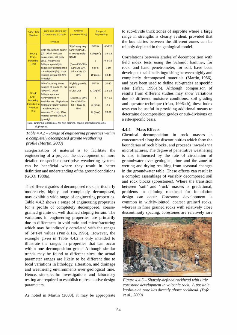
dominant A=accessory, Properties
Fabric and Mineralogy Grading D=dominant, SD=sub- (on remoulding) Engineering
"CDG" End Range of
Member
Tr=trace
Silty/clayey very SPT-N 60-120 Little alteration to quartz sandy GRAVEL
Strong’ (D). Alkali feldspars or very gravelly d(Mg/m3) 1.6-1.8‘ ץEnd – some pores, still gritty SAND
bordering (SD). Plagioclase e 0.4-0.6 HDG feldspars partially to (Gravel 30-50%,
completely decomposed Sand 30-50%, c′(kPa) 0-10 => halloysite (Tr). Clay Silt + Clay 10mineral content 10-25% 20%) Ø′ (deg.) 38-44 by weight.
Mircofracturing, some Slightly gravelly, SPT-N 10-40 solution of quartz (D, but sandy
lower %). Alkali SILT/CLAY d (Mg/m3) 1.2-1.5 ץ‘Weak’ feldspars porous, End – honeycombed => (Gravel 10-30%, e 0.7-1.1
bordering kaolinite (A). Plagioclase Sand 30-50%, transition to feldspars virtually absent Silt + Clay 30- c′ (kPa) 2-6
Residual => halloysite and 45%) Soil kaolinite (Tr - Nil). Clay Ø′ (deg.) 33-36
mineral content 30-50% by weight.
Note: Grading/properties are for free-draining, coarse-grained granite on a sloping site.
Table 4.4.2 – Range of engineering properties within a completely decomposed granite weathering profile (Martin, 2003)
categorisation of material is to facilitate the engineering of a project, the development of more detailed or specific descriptive weathering systems can be beneficial where they result in better definition and understanding of the ground conditions (GCO, 1988a).
The different grades of decomposed rock, particularly moderately, highly and completely decomposed, may exhibit a wide range of engineering properties. Table 4.4.2 shows a range of engineering properties for a profile of completely decomposed, coarse-grained granite on well drained sloping terrain. The variations in engineering properties are primarily due to differences in void ratio and microfracturing which may be indirectly correlated with the ranges of SPT-N values (Pun & Ho, 1996). However, the example given in Table 4.4.2 is only intended to illustrate the ranges in properties that can occur within one decomposition grade. Although similar trends may be found at different sites, the actual parameter ranges are likely to be different due to local variations in lithology, alteration, and drainage and weathering environments over geological time. Hence, site-specific investigations and laboratory testing are required to establish representative design parameters.
As noted in Martin (2003), it may be appropriate
to sub-divide thick zones of saprolite where a large range in strengths is clearly evident, provided that the boundaries between the different zones can be reliably depicted in the geological model.
Correlations between grades of decomposition with field index tests using the Schmidt hammer, for rock, and hand penetrometer, for soil, have been developed to aid in distinguishing between highly and completely decomposed materials (Martin, 1986), and have been used to define sub-grades at specific sites (Irfan, 1996a,b). Although comparison of results from different studies may show variations due to different moisture conditions, soil grading and operator technique (Irfan, 1996a,b), these index tests can be useful in providing additional means to determine decomposition grades or sub-divisions on a site-specifi c basis.
4.4.4 Mass Effects Chemical decomposition in rock masses is concentrated along the discontinuities which form the boundaries of rock blocks, and proceeds inwards via microfractures. The degree of penetrative weathering is also influenced by the rate of circulation of groundwater over geological time and the zone of wetting and drying resulting from seasonal changes in the groundwater table. These effects can result in a complex assemblage of variably decomposed soil and rock blocks (corestones). Where the transition between ‘soil’ and ‘rock’ masses is gradational, problems in defining rockhead for foundation design can occur. Corestone development is common in widely-jointed, coarser grained rocks, whereas in finer grained rocks with relatively close discontinuity spacing, corestones are relatively rare
Figure 4.4.5 – Sharply-defined rockhead with little corestone development in volcanic rock. A possible kaolin-rich zone lies directly above rockhead (Fyfe et al., 2000)
64

The site
Joints tight
No Corestones Corestones
10 m
FOOT-WALL HANGING WALL FAULT ZONE
Altered and mineralised Rock structure largely gone
Rockmass loose
WEST EAST
Figure 4.4.6 – Corestone development influenced by looseness of the rock mass on the hanging-wall side of a fault in northwest Kowloon (Whiteside, 1988)
and the soil to rock interface is often sharply defined (Figure 4.4.5).
In some situations, particularly where steeply dipping joints are relatively widely spaced, or where the flow of groundwater is concentrated in low-angle stress-relief joints (see Section 5.2.4), the weathering may bypass large tabular blocks of rock, resulting in coreslabs being left within the weathering profile (Fyfe et al., 2000).
Figure 4.4.6 shows an actual weathering profi le in northwest Kowloon, based on the logs from over 100 hand-dug caissons and mapping records of temporary foundation excavations. The overall rockhead profile is influenced by a major fault zone, joints sub-parallel to the fault creating sharp steps up to 8 m in height, and sub-horizontal sheeting joints. On the footwall side of the fault, the joints were very tight, and few corestones were encountered. The development of a thick zone of corestones, resulting in a much more gradational weathering profile on the hanging-wall side of the fault, was attributed to the looser condition of the rock mass and preferential groundwater fl ow in the open discontinuities (Whiteside, 1988).
Where corestone-rich masses become exposed at the ground surface, the additional resistance of the
corestones to erosion causes them to weather proud of the soil profile, leading to the development of tors of bare rock and surface boulders.
The main scheme that is used in Hong Kong for the classification of rock mass weathering (Partial Weathering or ‘PW’ scheme) is shown in Table 4.4.3 (GCO, 1988a). An older scheme based on Ruxton & Berry (1957) is included in the Geotechnical Manual for Slopes (GCO, 1984). The PW scheme is based on the percentage volume of rock within the mass and whether or not the soil matrix retains the mass structure, material texture and fabric of the parent rock (i.e. saprolite). In most cases information on the three dimensional extent of the mass is limited and it is usually only possible to make a rough estimate of the percentages. Although GCO (1988a) defines saprolite as the non-rock material within the partially weathered (PW 90/100 to PW 0/30) mass, the term is also commonly used when referring in general terms to the PW 0/30 and PW 30/50 masses.
For some engineering applications, in addition to the PW scheme, more detailed descriptions may be required. For example, the ground may need to be defined in terms of the proportions of material with different weathering grade, rock strength, percentage core recovery, joint spacing and joint condition, and
65

Table 4.4.3 – Comparison of Geoguide 3 (GCO, 1988a) and Geotechnical Manual for Slopes(GCO, 1984) schemes for classifying weathered rock masses
Figure 4.4.7 – Schematic PW weathering scheme applied to a mass exposure and other possible boundaries based on engineering requirements (after GCO, 1988a)
66

in some cases, a rock mass classifi cation system. Where descriptive terms such as ‘rockhead’ are used, their engineering geological characteristics and scope of applicability should be well defi ned to avoid ambiguity.
Figure 4.4.7 shows a schematic weathering profile which demonstrates the PW scheme applied to a mass exposure and shows boundaries based on other possible engineering requirements.
Figure 4.4.8 shows a schematic depiction of rock volume percentages, some possible correlations with rock core recovery, and an illustration of the potential effect of the ratio between block size and excavation dimensions on the relative ease of excavation. The correlations with rock core recovery demonstrate that the rock volume percentage can be much lower than the percentage of rock recovered, particularly where the blocks are evenly spaced and equi-dimensional (see Figure 4.4.8 c, d). However, the differences will tend to be smaller where the blocks are more randomly arranged, or where they are markedly anisotropic in
dimensions (see Figure 4.4.8 e).
Figure 4.4.8 c, d also demonstrate that the percentage of rock recovered in a drillhole may vary depending on its location relative to the vertical columns of blocks. The chance of encountering no rock at all in differently positioned vertical drillholes would vary (compare Figure 4.4.8 c, d). Although the block arrangement is highly stylised, similar situations can occur where development of corestones is strongly influenced by sub-vertical jointing. A thorough understanding of the development and associated distribution of corestones and their likely variations needs to be exercised to plan any necessary investigations to better define the actual ground conditions.
Figure 4.4.8 also highlights possible differences between area measurements in 2-dimensional exposures and equivalent PW percentage by volume. With care, similar diagrams can be constructed to aid visual assessments of PW percentages in outcrops or excavations.
Small block : excavation size ratio gives relatively easy excavation conditions
Large block : excavation size ratio gives relatively difficult excavation conditions
Figure 4.4.8 – Schematic depiction of rock percentage and correlation with rock core recovery (assuming recovery of 100% of the rock material). Very idealised jointing patterns and equi-dimensional blocks are shown. The percentage of rock in the ground in proportion to the percentage of rock core recovered will be larger with increasing randomness in block arrangement and increasingly poor drilling practice.
67

Although the presence of corestones can enhance the stability of slopes due to deflection of any potential shear surfaces through the soil mass, an important caveat is that the presence and orientation of any discontinuities within the saprolite or within the corestones that could reduce shear strength or lead to adverse groundwater conditions must also be investigated and their effect on stability should be assessed (Irfan & Tang, 1993).
There is evidence that some ground movement takes place during weathering to accommodate changes in stress. Such movement may result in the generation of slickensides on relict joints resulting in a reduction in shear strength (Parry et al., 2000). Hencher (2006) suggests that additional joints may be generated by such processes.
4.4.5 Variation in Engineering Rockhead The term ‘rockhead’ as used in engineering is the level at which the engineering parameters of the rock mass satisfy the design parameters for the project. These requirements vary considerably, for example rockhead can signify the depth to which the ground can be excavated mechanically without blasting, or
it can signify the top of rock with a required bearing capacity. As such, engineering rockhead is project and site specific and its determination can be one of the most critical issues for construction purposes (Figure 4.4.7).
Given the complex inter-relationship between lithology, fabric, structure and weathering, the level of engineering rockhead across a site is usually subject to considerable variation. However, engineering geological skills and experience can be applied to reduce the uncertainty.
Major variations in engineering rockhead level are commonly caused by geological structures (see Section 4.2). On a small to medium scale, the presence of corestones and steep steps in engineering rockhead along individual discontinuities may lead to irregularities in the rockhead profile which can be much more pronounced than data from widely-spaced drillholes may indicate (Shaw, 1997). The probability of a widely-spaced drilling pattern intersecting the lowest and highest points of an irregular rockhead profile is small.
Figure 4.4.9 − Schematic geological map and section developed from borehole data and local geological knowledge showing highly variable rockhead surface (Fletcher, 2004)
68

Figure 4.4.9 shows a schematic geological map and section for a site with a highly variable engineering rockhead profile caused by a granodiorite intrusion which is sheared along its fl anks. Whilst some initial drillhole data was available, knowledge of the regional and local structural geology was necessary to produce a representative geological model of the site. An inclined drillhole later confi rmed the model. Smooth rockhead profiles drawn between the drillhole locations can only reflect the general profile, since weathering progresses preferentially along the discontinuities. In this example, the inclined rock structure could lead to overhanging rock or quartz veins with intervening saprolite which could prove problematic for bored pile foundations.
4.4.6 Subsurface Processes
General Subsurface erosion and transportation (eluviation) of the fine materials and solutes produced by weathering in situ is an important process which leads to the creation of interconnected voids in saprolite and transported soils. This increases the void ratio and permeability of the soil. Where suffi cient hydraulic gradient exists in saprolite and transported soils, through-flow of groundwater may cause larger scale internal erosion leading to the development of soil pipes (Nash & Dale, 1984). These can be of major hydrogeological importance (Section 4.6) and have also been implicated in many slope failures (Section 6.4) where they have become blocked or constricted due to collapse or sedimentation.
Deposition (illuviation) of material, for instance in joints, can lead to decreases in permeability. High concentrations of low strength clay minerals such as kaolin have been implicated in some large scale slope failures in Hong Kong, e.g. Campbell & Parry (2002).
Solution was the major process in the formation of the buried karst in Hong Kong. Solution of pure marble leaves only minor amounts of residual material which may be deposited in the cavities along with other, in-washed detrital material (see Sections 5.5 and 6.5 for further details).
Eluviation and Development of Soil Pipes Eluviation involves the transportation of solutes and fines produced as a by-product of in situ weathering of rock masses (Section 4.4.3) by intergranular flow
Figure 4.4.10 – Soil pipe about 1 m across, near the colluvium/saprolite interface at Lai Ping Road Landslide (Koor & Campbell, 2005)
of groundwater through the soil mass, and also via pervasive, interconnected pores, open joints and soil pipes which may range in aperture from less than 0.5 mm to more than 1 m. This process is also common in superficial deposits such as colluvium where groundwater flow occurs (Figure 4.4.10).
Development of soil pipes is an important hydrogeological process which infl uences hillslope drainage, eluviation and slope instability. A model for development of soil pipes is given in Nash & Dale (1984), and the key diagrams are shown in Figures 4.4.11 and 4.4.12. Soil pipe s evolve progressively, leading to interconnection of voids and further erosion and expansion of the pipe. Although most reported examples have been in connection with the investigation of shallow landslides, generally involving less than 2 m thickness of regolith, a pipe network at the base of saprolite more than 10 m thick was described by Whiteside (1996), and infilled pipes were identified at greater depth in granite saprolite in northeast Kowloon (HAPL, 1998b). It is estimated that 95% of all groundwater fl ow in
69
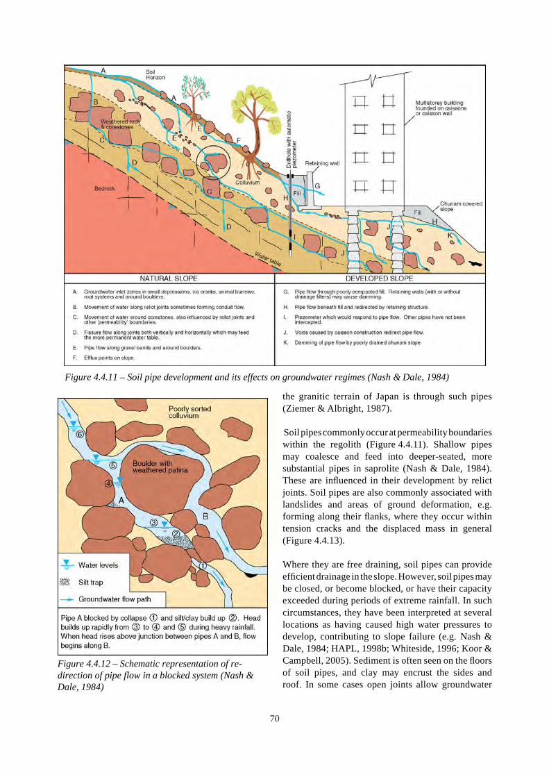
Figure 4.4.12 – Schematic representation of re-direction of pipe flow in a blocked system (Nash & Dale, 1984)
Figure 4.4.11 – Soil pipe development and its effects on groundwater regimes (Nash & Dale, 1984)
the granitic terrain of Japan is through such pipes (Ziemer & Albright, 1987).
Soil pipes commonly occur at permeability boundaries within the regolith (Figure 4.4.11). Shallow pipes may coalesce and feed into deeper-seated, more substantial pipes in saprolite (Nash & Dale, 1984). These are influenced in their development by relict joints. Soil pipes are also commonly associated with landslides and areas of ground deformation, e.g. forming along their flanks, where they occur within tension cracks and the displaced mass in general (Figure 4.4.13).
Where they are free draining, soil pipes can provide efficient drainage in the slope. However, soil pipe s may be closed, or become blocked, or have their capacity exceeded during periods of extreme rainfall. In such circumstances, they have been interpreted at several locations as having caused high water pressures to develop, contributing to slope failure (e.g. Nash & Dale, 1984; HAPL, 1998b; Whiteside, 1996; Koor & Campbell, 2005). Sediment is often seen on the floors of soil pipes, and clay may encrust the sides and roof. In some cases open joints allow groundwater
70
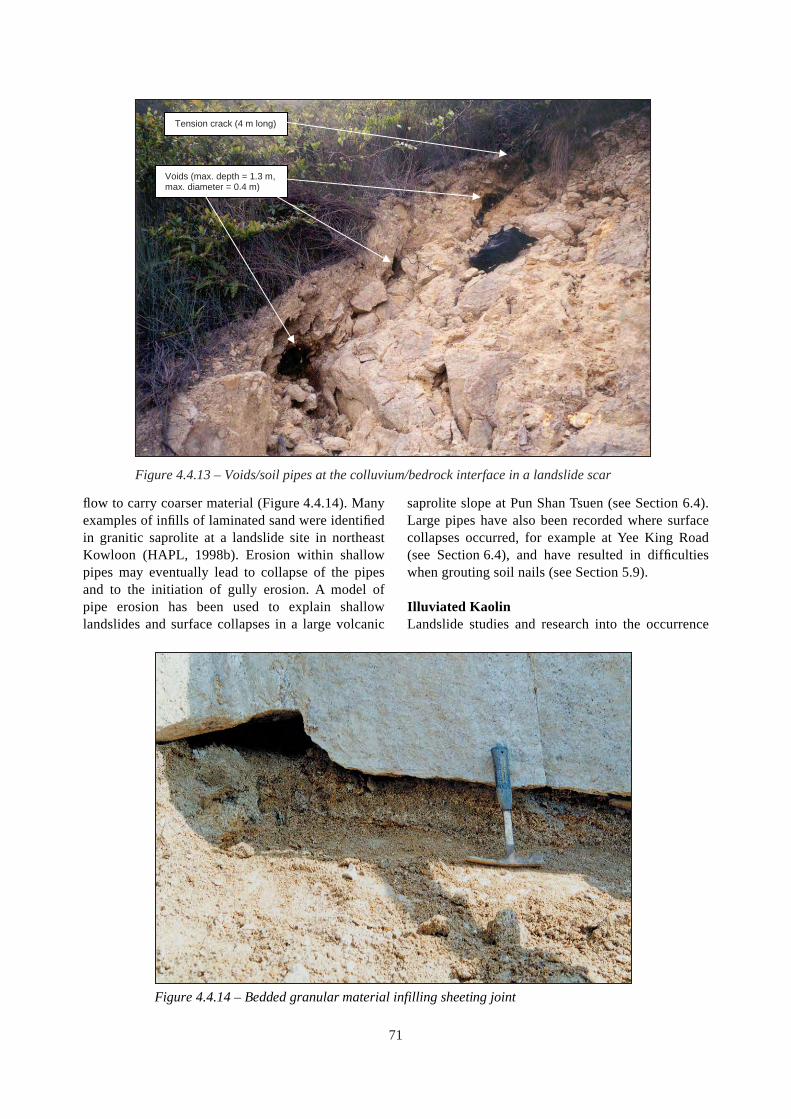
Tension crack (4 m long)
Voids (max. depth = 1.3 m, max. diameter = 0.4 m)
Figure 4.4.13 – Voids/soil pipes at the colluvium/bedrock interface in a landslide scar
flow to carry coarser material (Figure 4.4.14). Many saprolite slope at Pun Shan Tsuen (see Section 6.4). examples of infills of laminated sand were identified Large pipes have also been recorded where surface in granitic saprolite at a landslide site in northeast collapses occurred, for example at Yee King Road Kowloon (HAPL, 1998b). Erosion within shallow (see Section 6.4), and have resulted in difficulties pipes may eventually lead to collapse of the pipes when grouting soil nails (see Section 5.9). and to the initiation of gully erosion . A model of pipe erosion has been used to explain shallow Illuviated Kaolin landslides and surface collapses in a large volcanic Landslide studies and research into the occurrence
Figure 4.4.14 – Bedded granular material infilling sheeting joint
71

Buff kaolin in a 50° dipping, decomposed zone up to 12 m below rockhead
Figure 4.4.15 – Typical appearance of a thick kaolin infill in granite
and properties of kaolin-rich zones in Hong Kong suggest that much of the kaolin accumulation in discontinuities in Hong Kong is primarily a weathering product which has been transported by eluviation, mainly in solution, and deposited by illuviation. As such it is more likely to occur along discontinuities close to, and above the soil to rock interface or where there are other such similar hydrogeological boundary conditions causing preferential groundwater flow (Campbell & Parry, 2002). For example, these
conditions can occur along the interface between extensive coreslabs and saprolite in plutonic rocks.
Kaolin infilling of discontinuities is relatively common especially within stress-relief joints. Clay infilling may be located along several sets of joints within the weathering profile depending on the variability of past groundwater regimes, weathering and joint development history. Some examples of failures along kaolin-infilled discontinuities and
Possible ancient landslide site
Sheared kaolin along part of main surface of rupture
Figure 4.4.16 – August 1995 Shum Wan Road Landslide (GEO, 1996b and Kirk et al., 1997)
72

A
A A
A1963 – Ancient landslide scars in
natural coastal hillside
1972 – Massive failure when cut
slope formed
Kaolin-rich clay seams in
disturbed zones above rockhead
Section A-A
Figure 4.4.17 – 1972 Lai Cho Road Landslide (MGSL, 2002 and Thorn et al., 2003)
their engineering implications are given in Campbell & Parry (2002).
Kaolin infills have also been recorded within shear zones and dilated discontinuities associated with past landsliding. These infills are commonly light buff to dark brown in colour, due to the inclusion and weathering of rock fragments (Campbell & Parry, 2002). Because the kaolin can be difficult to recover and identify using standard methods of drillhole investigation, understanding its genesis and potential distribution is key to the identification of kaolin-rich zones at the site investigation and design stages.
Figure 4.4.15 shows a thick kaolin zone in granite, where the buff colour suggests movement during its formation, while Figures 4.4.16 and 4.4.17 show prominent landslide sites involving kaolin-rich seams. The 1995 Shum Wan Road landslide (GEO 1996c,d; Kirk et al., 1997) and the 1972 Lai Cho Road landslide (MGSL, 2002; Thorn et al., 2003) are coastal sites with evidence of ancient landslides.
Examples of other prominent landslides involving kaolin-rich infills such as the 1995 Fei Tsui Road (GEO 1996a,b) and 1999 Shek Kip Mei (FMSW 2000) landslides are given in Section 6.4.
4.5 GEOMORPHOLOGICAL PROCESSES
4.5.1 Introduction Geomorphological processes encompass all forms of surface erosion and deposition including colluvial, fluvial and coastal processes. These processes have shaped the present-day topography and are of fundamental importance in understanding the engineering geological characteristics of the Hong Kong landscape.
Engineering geological issues include: • identifying the various processes currently active
and those which have affected the terrain in the past, and
73
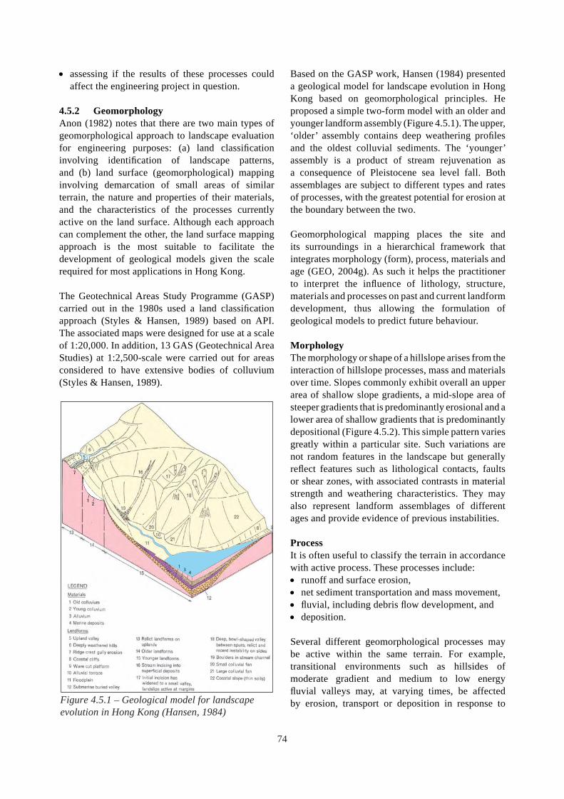
• assessing if the results of these processes could affect the engineering project in question.
4.5.2 Geomorphology Anon (1982) notes that there are two main types of geomorphological approach to landscape evaluation for engineering purposes: (a) land classification involving identification of landscape patterns, and (b) land surface (geomorphological) mapping involving demarcation of small areas of similar terrain, the nature and properties of their materials, and the characteristics of the processes currently active on the land surface. Although each approach can complement the other, the land surface mapping approach is the most suitable to facilitate the development of geological models given the scale required for most applications in Hong Kong.
The Geotechnical Areas Study Programme (GASP) carried out in the 1980s used a land classification approach (Styles & Hansen, 1989) based on API. The associated maps were designed for use at a scale of 1:20,000. In addition, 13 GAS (Geotechnical Area Studies) at 1:2,500-scale were carried out for areas considered to have extensive bodies of colluvium (Styles & Hansen, 1989).
Figure 4.5.1 – Geological model for landscape evolution in Hong Kong (Hansen, 1984)
1 4
3
Based on the GASP work, Hansen (1984) presented a geological model for landscape evolution in Hong Kong based on geomorphological principles. He proposed a simple two-form model with an older and younger landform assembly (Figure 4.5.1). The upper, ‘older’ assembly contains deep weathering profiles and the oldest colluvial sediments. The ‘younger’ assembly is a product of stream rejuvenation as a consequence of Pleistocene sea level fall. Both assemblages are subject to different types and rates of processes, with the greatest potential for erosion at the boundary between the two.
Geomorphological mapping places the site and its surroundings in a hierarchical framework that integrates morphology (form), process, materials and age (GEO, 2004g). As such it helps the practitioner to interpret the influence of lithology, structure, materials and processes on past and current landform development, thus allowing the formulation of geological models to predict future behaviour.
Morphology The morphology or shape of a hillslope arises from the interaction of hillslope processes, mass and materials over time. Slopes commonly exhibit overall an upper area of shallow slope gradients, a mid-slope area of steeper gradients that is predominantly erosional and a lower area of shallow gradients that is predominantly depositional (Figure 4.5.2). This simple pattern varies greatly within a particular site. Such variations are not random features in the landscape but generally reflect features such as lithological contacts, faults or shear zones, with associated contrasts in material strength and weathering characteristics. They may also represent landform assemblages of different ages and provide evidence of previous instabilities.
Process It is often useful to classify the terrain in accordance with active process. These processes include: • runoff and surface erosion, • net sediment transportation and mass movement, • fluvial, including debris flow development, and • deposition.
Several different geomorphological processes may be active within the same terrain. For example, transitional environments such as hillsides of moderate gradient and medium to low energy fluvial valleys may, at varying times, be affected by erosion, transport or deposition in response to
74

Figu
re 4
.5.2
– G
eolo
gica
l m od
el o
f the
eas
tern
flan
k of
Tsi
ng S
han
show
ing
the
inte
ract
ion
of g
eolo
gy, t
opog
raph
y an
d ge
omor
phol
ogy
on la
ndsl
ide
initi
atio
n, tr
ansp
ort a
nd d
epos
ition
pro
cess
es (F
letc
her e
t al.,
200
2)
Sapr
olite
Zon
eA
D
epos
ition
Zon
eB
Tr
ansp
ort Z
one
C
Tran
spor
t and
Entra
inm
ent Z
one
D
Tran
spor
t and
Dep
ositi
on Z
one
E D
epos
ition
Zon
eF
Reg
olith
Cla
ssifi
catio
n
Bg
Gra
nite
Bed
rock
(Gra
de II
I - I)
Sg
Gra
nite
Sap
rolit
e (G
rade
IV -
V)
Sv
Volc
anic
Sap
rolit
e (G
rade
IV -
V)
Cr
Res
idua
l Col
luvi
umC
lb
Rel
ict L
ands
lide
Col
luvi
umC
d D
epre
ssio
n C
ollu
vium
Crf
Ta
lus
Faul
tSh
ear Z
one
Mas
ter J
oint
s
Meg
acry
stic
Gra
nite
Volc
anic
last
ic S
edim
ents
And
esite
490
m 10
0
Topp
ling
plan
es
Bg
Cd
- Acc
umul
atio
n of
bou
lder
y co
lluvi
umw
ithin
a d
epre
ssio
n. T
he d
epre
ssio
nus
ually
cor
resp
onds
to th
e in
ters
ectio
nbe
twee
n th
e m
ain
stru
ctur
al d
isco
ntin
uitie
s
Bg
Tran
spor
t zon
e - T
rans
port
of la
ndsl
ide
debr
is a
long
stru
ctur
ally
con
trolle
ddr
aina
ge li
nes Clb
and
Crf
- A
ccum
ulat
ion
of b
ould
ery
collu
vium
with
in th
e en
train
men
t zon
e
Tran
spor
t and
Dep
ositi
on Z
one
with
min
or e
ntra
inm
ent
Sedi
men
tary
inte
rbed
s(o
vers
teep
ened
slop
es)
Mou
th o
f dra
inag
e lin
e, c
orre
spon
ding
to th
e co
ntac
t bet
wee
n th
e vo
lcan
icla
stic
sedi
men
ts a
nd th
e an
desi
te. A
t thi
s loc
atio
nth
e dr
aina
ge li
ne c
hang
es fr
om b
eing
narr
ow a
nd st
eep
to b
road
and
flat
Star
t of m
ain
depo
sitio
n zo
ne
Lobe
s of C
lb
Dee
p se
ated
failu
res
with
in th
e w
eath
ered
ande
site
Foot
hills
Byp
ass
Meg
acry
stic
Gra
nite
Vo
lcan
icla
stic
Sed
imen
ts
silts
tone
, san
dsto
ne, t
uffit
e A
ndes
ite
1200
m
Gra
nitic
rock
out
crop
s, pu
nctu
ated
by c
ollu
vium
fille
d, st
ruct
ural
lyco
ntro
lled
depr
essi
ons.
Thes
ede
pres
sion
s for
med
the
sour
cear
eas f
or th
e 19
90 T
sing
Sha
nan
d 20
00 T
sing
Sha
n la
ndsl
ides
Gra
nitic
rock
out
crop
s, w
ith tr
ansp
ort
of la
ndsl
ide
debr
is a
long
stru
ctur
ally
cont
rolle
d gu
llies
Acc
umul
atio
n of
col
luvi
um (C
la a
nd C
lb)
at th
e co
ntac
t bet
wee
n th
e gr
anite
and
the
volc
anic
last
ic se
dim
ents
. The
199
0 an
d20
00 T
sing
Sha
n la
ndsl
ides
ent
rain
edsi
gnifi
cant
qua
ntiti
es o
f col
luvi
um in
this
zone
.
(rel
ict)
land
slid
e de
bris
coa
lesc
ing
tofo
rm a
serie
s of l
obat
e fe
atur
es. I
n ar
eas,
thes
e lo
bate
dep
osits
app
ear t
o ha
vebu
ilt u
p on
top
of e
ach
othe
r, w
ith th
ela
rger
, old
er d
epos
its o
verla
in b
y th
esm
alle
r, yo
unge
r dep
osits
.
Lege
nd:
A S
apro
lite
Zone
B
Dep
letio
n Zo
ne
C
Tran
spor
t Zon
e
D
Tran
spor
t and
Ent
rain
men
t Zon
e
E Tr
ansp
ort a
nd D
epos
iton
Zone
F M
ain
Dep
ositi
on Z
one
- with
the
larg
er
Sv
Sv
75

rainfall, landslides, fl ooding or drought. An example of the interaction of topography, geology, and geomorphology on landslide initiation, transport and deposition is shown schematically in Figure 4.5.2. Such models can be used for understanding the dynamics of evolution of the local terrain and associated geological hazards.
The recognition of active processes related to progressive deterioration, such as weathering, changes in the hydrogeological regime and slope movements, can be facilitated by geomorphological mapping. Progressive deterioration can lead to increased water ingress and modify subsurface water flow conditions in soil pipes and joints, thus changing the potential for hazard on a local scale.
Materials Geomorphological processes are generally restricted to the regolith, and exposed rock masses. Regolith comprises superficial deposits and saprolite. Mapping of the regolith sub-divides saprolite and transported superficial material according to their different properties and behaviour (Figure 3.2.3). Site-specific classes of regolith have been developed for some individual studies (MFJV, 2002b).
Mapping the regolith can be a useful interpretative tool as information can be obtained about several other terrain characteristics such as relative age, morphology and processes. However, for some sites, there may not be sufficient contrast or diversity in the regolith units mapped for these to be of key importance in susceptibility analysis (OAP, 2004a). Consideration of potential differences in the geotechnical behaviour of the slope-forming materials in different hillside settings can help to increase the usefulness of regolith mapping (see Section 6.2.4).
In addition to regolith, the possible influence of lithology and structure should be considered in geomorphological mapping. Site evaluation at larger scales may reveal site-specific lithological or structural factors that influence both the geomorphology and the hazards, e.g. Fletcher et al. (2002).
Age The evaluation of relative age of units of terrain and previous instability of natural terrain allows a degree of understanding of the past and present activity of the site in terms of instability or mass wasting. Although
geomorphological mapping allows only relative dating, a prediction of future activity is possible. While intense rainfall is the main trigger of natural terrain landslides in Hong Kong, longer duration environmental changes have an important influence on stability of terrain. Significant climatic variations during the Quaternary Period have infl uenced the rates of hillslope processes such as weathering, erosion and landsliding. In particular, episodic changes in sea level promote fl uvial downcutting during low sea level stands, and deposition of unconsolidated material (potential for entrainment) on lower slope areas during high sea level stands. An understanding of such time-dependent variations in the landscape can help to interpret zones of relative hazard activity.
An example is the evolutionary model developed by Hansen (1984); see Figure 4.5.1. Although this regional model may not be directly applicable to every site, it is based on local experience and generally accepted geomorphological principles. The concept of upper and lower landform assemblages with relatively high rates of erosion and mass movement near the boundary between the two landform types
Figure 4.5.3 – The 1990 Tsing Shan debris flow
76

Figure 4.5.4 – Typical natural terrain hazards in Hong Kong (GEO, 2000)
has been shown to be useful in identifying areas with Figure 4.5.3 shows large-scale mass movement and relatively high landslide intensity (see the Cloudy Figure 4.5.4 shows a schematic representation of Hill example in Section 6.2). typical natural terrain hazards.
Dating techniques can provide more precise Types of mass movement include: absolute age information than geomorphological x� deep-seated landslides, commonly associated with interpretation. Sewell & Campbell (2005) report thick or deeply weathered, weak regolith, and high on a suite of techniques for dating natural terrain groundwater levels, landslides and rock surfaces in Hong Kong. Their x� debris slides, avalanches and channelised debris results suggest that some large relict landslides are tens of thousands of years old, and therefore the landslides may have occurred under different environmental conditions than those pertaining in more recent times. Ages of events are important for magnitude and frequency analyses for hazard assessment (Section 6.2). However, the time-constraints of most engineering projects limit the use of dating techniques which often require considerable time to complete.
4.5.3 Mass Movement Mass movements have played a significant part in forming the present-day landscape of Hong Kong, including the formation of extensive colluvial deposits which can reach a thickness of about 25 m in the Mid-levels area of Hong Kong Island.
Figure 4.5.5 – Debris avalanches and debris flows below steep cliff near Ngong Ping, Lantau
Steep cliff with associated rock falls giving rise to
talus accumulation at toe
Landslides in talus-covered saprolite giving rise to debris
avalanches and flows
77

flows, typically originating from over-steepened terrain,
• rockfall from cliffs (Figure 4.5.5) caused by dilation, toppling or sliding promoted by cleft-water pressure build-up or root wedging, and
• boulder falls caused by erosion of the saprolite or colluvium matrix with consequent undermining on steep slopes.
Evidence of mass movement such as degraded, amphitheatre-shaped depressions in hillsides and large colluvial lobes near the base of hillsides can be seen in many places in Hong Kong. However, in many cases debris may be absent or it may not be possible to link the debris present with the source area. Consequently considerable skill, and often detailed mapping, is required to determine whether such features are degraded large landslides or the result of the coalescence of a number of smaller landslides or erosional features. Even if the failures resulted from a single event, this may have occurred under very different environmental conditions from those pertaining in more recent times. The application of geomorphological knowledge and skills is therefore required to identify and interpret the potential implications of the occurrence of debris lobes and hillside depressions on potential landslide activity given the current geomorphological conditions.
4.5.4 Fluvial Processes Surface erosion primarily takes place by gully erosion, sheet erosion and stream bank erosion (Fyfe et al., 2000). Gully erosion is most active on saprolite in upland areas with sparse vegetation and is especially prevalent on well-drained granitic soils, particularly at breaks in slope. Gullies tend to coalesce and form dendritic patterns in granitic terrain and are relatively common in areas west of Tsing Shan and between Siu Lam and Tai Lam in the New Territories.
Most valleys are short in length, with a sharp change in gradient at the foot of the bordering hillsides. Low alluvial terraces are formed of generally well-sorted sand and gravel deposits which are laid down and re-worked as the alluvial channels meander. These deposits may inter-digitate with colluvium near the foot of the hillsides. Finer-grained lagoon deposits may also develop behind beach bars where the valleys drain into sheltered bays.
The Yuen Long floodplain is the most extensive area of flat-lying ground in Hong Kong and is formed from
alluvial deposits overlying Holocene marine deposits and Pleistocene alluvium with buried channels. The main streams and rivers typically meander, but the development of fi sh ponds, flood protection works and fill platforms have largely arrested their natural migration.
4.5.5 Coastal and Offshore Processes Much of the eastern and southern coastline of Hong Kong is exposed to the prevailing wind and waves, and is generally a high-energy erosive environment, characterised by the development of extensive sections of crenulated, rocky cliffs, with beaches and other depositional features being confined to the more sheltered bays. The western coastline is generally more sheltered, and depositional processes prevail. The influences of the sediment-laden Pearl River and the Yuen Long floodplain have given rise to the mudflats, mangroves and intricate tidal channels of Deep Bay. In the wet season, the effect of the Pearl River discharge is greatest. At this time, the discharge penetrates into western and central waters and can carry a high level of suspended sediment. Eastern waters are far less influenced by the Pearl River.
The depth of Hong Kong waters generally increases from northwest to southeast. The depth of water is generally less than ten metres in the northwest, near the Pearl River estuary. It becomes ten to twenty metres deep in the central harbour area, and it is about thirty metres deep in south-eastern waters. Tidal flows are the dominant influence in inshore areas with current speeds in excess of 2 m/s in constricted channels but 0.5 m/s or less in sheltered waters. The pattern of tidal currents is complex but the strongest currents and residual currents are in a generally southeast-northwest direction and this is refl ected by two main tidal channel networks which are fi fteen to twenty metres deeper than the surrounding sea bed.
The pattern of distribution of sea bed sediment reflects both the hydraulic conditions and the topography of the sea bed. The sea bed comprises mostly soft clayey silt with associated layers of suspended mud. Coarser sediments such as sands, gravels and cobbles occur close to the coast, islands, submarine rock outcrops and in constrained channels, where current speeds prevent sedimentation of fi ne material. This is a reflection of increased wave action in shallow water and increased currents around shoals, headlands and in channels (Fyfe et al., 2000).
78

4.5.6 Influence of Quaternary Fluctuations in Sea Level
During the Quaternary Period, the lowest sea level was about 120 m to 130 m below the present sea level, and the shoreline was approximately 120 km south of the current position. This resulted in the formation of an extensive network of streams and rivers in which the predominantly fl uvial materials of the Chek Lap Kok Formation were deposited (see Section 5.8). These include complex palaeochannel deposits of gravel and cobbles and local desiccation crusts in marine and estuarine deposits which have been mapped during investigations for reclamations such as Chek Lap Kok airport and Tseung Kwan O New Town (Fyfe et al., 2000). Sub-aerial weathering during low sea levels has also led to the development of saprolite and karst solution features extending more than 100 m below the present sea level.
Approximately 6,000 years ago, the sea level was up to 2 m higher than at present, leading to the development of raised beaches and stranded sea cliffs which are now best preserved in the Tuen Mun valley and between Yuen Long and Lo Wu (Fyfe et al., 2000).
4.6 HYDROGEOLOGICAL PROCESSES
4.6.1 Introduction Hydrogeology is of major geotechnical importance in Hong Kong, with uncertainty regarding the groundwater regime often being a key issue in many types of engineering applications, such as slope stability, deep excavations and tunnels.
Engineering geological issues include: • Ηeterogeneous and discontinuous geological
materials with complex contrasts in permeability, particularly at the site-scale including: o highly transmissive pathways such as soil
pipes, open discontinuities and coarse-grained superficial deposits, and
o perching, confinement or damming of groundwater due to relatively impermeable barriers at interfaces between materials of contrasting permeability, e.g. lithological boundaries, decomposed dykes, faults and deep foundations such as diaphragm walls and rows of closely-spaced piles.
• Settlement of unconsolidated deposits (e.g. new reclamation) in response to groundwater
abstraction or flow into deep foundation and tunnel excavations during construction.
Many of these issues are discussed in the context of the engineering geological characteristics of Hong Kong rocks and soils in Chapter 5 and specific engineering applications in Chapter 6. This section is primarily intended to provide an introduction to the main hydrogeological processes, and illustrations of hydrogeological complexity with particular reference to groundwater in slopes and tunnels.
4.6.2 Hydrogeological Environments The main processes involved in the hydrological cycle are precipitation, evaporation, transpiration, surface fl ow, infiltration and groundwater fl ow. At very large or very small scales, where relative homogeneity is often assumed, the effect of these processes can be demonstrated using simple physical models. Figure 4.6.1 shows the material variability within the Chek Lap Kok Formation. On a large scale, the ground could be modelled for engineering design purposes as one material which has a representative
Figure 4.6.1 – Silty clay with sand laminae and lenses from the Chek Lap Kok Formation (Fyfe et al., 2000)
79

set of anisotropic compressibility and permeability characteristics, even though on a small scale the sample is composed of distinct layers of clay and sand with vastly different properties. Similarly, the numerical modelling for a major hillslope in the Mid-levels Study (GCO, 1982) considered all types of rock as a single aquifer. However, the discussion on the effects of tunnelling on the hydrogeological regime in Section 6.7 illustrates that zones of relatively high transmissivity can occur along fractured zones associated with faulting and stress-relief.
In many cases, a large amount of uncertainty may exist due to the heterogeneous nature of the ground, the impracticality of defining it in detail and potential future changes in environment. The variability of hydrogeological characteristics is primarily due to the geological origins and the subsequent effects of the processes described in Sections 4.2 to 4.5.
In addition, the groundwater regime is affected by environmental influences which include: • long term variations in precipitation and infiltration
due to changes in climate and vegetation cover, • annual variations in precipitation, • seasonal rainfall, frequently resulting in large and
complex variations in transient groundwater levels in response to individual rainstorms, antecedent rainfall and overall seasonal variations,
• variations in infiltration due to construction, cultivation, hill-fires, bioturbation and opening-up of fissures due to desiccation, movement or stress-relief,
• coastal processes such as tides and wave action, and
• long term sea level variations.
4.6.3 General Hydrogeological Characteristics
Soils Groundwater in soils is characteristically inter-granular. The hydraulic properties of soils range very widely. Open textured soils (e.g. some bouldery colluvium) have high permeability, large storage capacity and change little in volume when dewatered. By contrast, clays (e.g. marine clay) have low permeability and graded soils (e.g. dense saprolite) have low storage capacity. Soft clays compress when dewatered. Soils can be subjected to eluviation that can result in mass leaching or internal erosion leading to the creation of soil pipes. Generally, volcanic saprolite has a higher content of fines and is less permeable than granitic saprolite.
Conductivity of soil masses depends on connectivity. For example, fine grained alluvial soils deposited in broad expanses such as floodplain deposits can provide extensive strata of low permeability. In contrast, coarser alluvial soils found in stream beds can behave as channelised, sometimes interconnected or braided, extensive aquifers. Alternatively, confined aquifers can occur where lenses of coarse soils lie within less permeable materials.
Perched water tables can develop above aquicludes, and temporary perched water tables can develop above contacts with less permeable layers. Upward hydraulic gradients giving rise to sub-artesian or even artesian conditions can develop in some hillsides due to confinement, or partial confinement by a less permeable layer (see Figure 4.6.5). Examples of the influence of the hydrogeological properties of stratified sediments on groundwater modelling for deep excavations and tunnelling are discussed in Sections 6.6 and 6.7 respectively.
Rock Generally, rock material is of low permeability and groundwater flow is dominated by discontinuities. Rock mass permeability may increase towards the soil to rock interface due to stress relief and correspondingly higher intensity of joints. Faults and dykes may be more transmissive in their plane, and act as aquitards normal to their plane. The influence of groundwater inflow on tunnelling and the extensive drawdown and settlement that this can cause in overlying soils are discussed in Sections 4.6.5 and 6.7.
Partially Weathered Rock Mass Owing to the presence of relict geological structure, saprolite can have a combination of hydrogeological characteristics of soil and of rock, with added complexity due to the variations between the properties of the soil material and those of the relict joints and any soil pipes. This can lead to complex hydrogeological regimes. A schematic model showing typical hydrogeological processes in a cut slope above the interface between soil and rock is shown in Figure 4.6.2.
4.6.4 Groundwater in Slopes A number of groundwater studies in Hong Kong (GCO, 1982; Insley & McNicholl, 1982; Li et al., 1995; Evans & Lam, 2003a,b; MFJV, 2004) have demonstrated that the piezometric response time to individual rainstorms generally increases with depth,
80

Partially clay infilled joint following
intermittent slope movement
Drop in velocity (loss of head) causes sediment
deposition
Shallow saturation results in small failures
during rainstorm
Original water table
Original ground surface
Cut
Seepage pressures induce piping along joints and
relatively rapid flow through system
Fault
Weathered dyke aquitard
Dyke Slow
infiltration
Rock exposure
100% run off
Overland flow
Rise
Erosion
Local perching
Water ingess into fractures, root holes etc.
Rapid recharge down fault zone
Cutting induces high hydraulic gradient
and internal erosion
Water into tension crack
Figure 4.6.2 – Schematic hydrogeological processes above the rockhead in a cut slope (after Hencher, 2000)
with sharper responses of shallow perched water In the case of shallow, perched water tables, the tables in colluvium or thin saprolite overlying shallow response curve is usually asymmetric with a sharp rock being common. Examples of slopes affected by response and slower rate of dissipation, though still groundwater and complex hydrogeological conditions relatively rapid. Examples of typical responses are are included in Section 6.4. shown in Figure 4.6.3 which depicts monitoring
results of shallow piezometers installed in mainly superficial material. Similar responses are also
Hourly Rainfall
Figure 4.6.3 – Results of automatic groundwater monitoring at shallow depth in natural terrain (Evans & Lam, 2003b)
81

‘Delayed
Rainfall and piezometer response
4
12
20
28
36
FILL
COLLUVIUM
CDG
HDG to SDG
SDG
CDG to MDG
Depth
‘Rapid response and noticeable decay of
perched water in colluvium
Delayed response and gradual rise of confined piezometric head below the rockhead
Delayed response and gradual rise of piezometric head in completely
decomposed rock
COLLUVIUM/CDG
Geology and piezometer depth
Figure 4.6.4 – Groundwater responses in colluvium and a weathered granite profile in the Mid-levels study area of Hong Kong Island (after GCO, 1982)
shown for two piezometers installed in colluvium in Figure 4.6.4.
Delayed but often large responses with relatively slow dissipation are commonly recorded in thick saprolite with increasing depth (Insley & McNicholl, 1982). In such cases, the base groundwater table may show a gradual rise throughout the wet season, with a less marked response to individual rainstorms. Examples of typical responses are shown in Figure 4.6.4 for two piezometers installed in granitic saprolite. Relatively rapid and large responses in thick weathering profiles and colluvium can also occur where a network of relatively open joints, fissures or soil pipes allow
rapid infiltration and conduct flow towards zones of lower mass permeability (Sun & Campbell, 1999).
Rock mass is often regarded as being less permeable than saprolite, but this may not be always the case. Figure 4.6.4 shows evidence of a zone of more permeable rock close to the interface between soil and rock, with a higher piezometric head in the lowest piezometer being partially confined by less permeable, moderately to completely decomposed rock mass above it. The upwards hydraulic gradient implied by the lowest three piezometers has been interpreted as evidence of upwards flow from a partially confined aquifer in the rock mass
82

Unweatheredrock
Figure 4.6.5 – Conceptual model of high permeability zone and confined groundwater below rockhead (after Jiao et al., 2003)
Infiltration
Colluvium, alluvium, fill (permeable) Saprolite (less permeable) Highly permeable zone below rockhead Slightly weathered to fresh bedrock
Boreholes at No. 52
Hollywood Road Piezometric head
in high permeability zone
(GCO, 1982). Figure 4.6.5 shows a conceptual hydrogeological model of this environment which was developed to explain the occurrence of artesian water in drillholes at Hollywood Road. Jiao (2000a) has also raised the possibility of partially confined groundwater having contributed to the delayed response and deep-seated failure of some large cut slopes in Hong Kong (Figure 4.6.6).
An example of an investigation using automatic monitoring of piezometers in joints in a rock slope is given by Richards & Cowland (1986). A section through the slope and the groundwater responses for a number of rainstorms are shown in Figure 4.6.7. The monitoring showed a high variability in response times and magnitude to different rainstorms, with no single piezometer responding to all the rainstorms. The monitoring also showed that transient groundwater pressures were not observed to occur simultaneously over the whole surface of an individual stress-relief joint, and that the groundwater pressures were much less than predicted by typical empirical equations.
As noted above, the groundwater regime in saprolite can be complex, with primary porosity (soil material) and secondary porosity systems comprising networks of relict discontinuities, fissures and soil pipes. The secondary porosity may result in a transmissivity much higher than the primary system. Conversely, geological features such as clay-infilled relict discontinuities may result in lower permeability and lead to local perching or retardation of slope drainage. A schematic
Piezometric head in Grades IIIII after heavy rainfall
Loading reduced when slope is excavated
Figure 4.6.6 – Conceptual model of possible hydrogeological influence on deep-seated failure of some cut slopes in Hong Kong (after Jiao, 2000a)
Depression in rockhead - possibly due to local
geological structure and/or increased rate of decomposition due to strong upward
flow from bedrock over geological time
83

Figure 4.6.7 – Automatic piezometer monitoring of rock slope sheeting joints for different rainstorms (Richards & Cowland, 1986)
model of primary and secondary porosity systems developed by Au (1990) to explain differences in responses of piezometers and of horizontal drains is shown in Figure 4.6.8. In this model, piezometer ‘X’ is likely to be more responsive to rainstorms than piezometer ‘Y’ because it has intersected a network
Secondary porosity system Horizontal drain Piezometer Primary
porosity system
Secondary porosity system
connected to ground surface
Post-drainage groundwater table
Pre-drainage groundwater table
Figure 4.6.8 – Schematic model of primary and secondary porosity systems and groundwater compartmentalisation in a slope (Au, 1990)
Figure 4.6.9 – Evidence of groundwater compartmentalisation from horizontal drain flow measurements (after Martin et al., 1995)
of discontinuities. Horizontal drain ‘A’ is also likely to be more responsive than ‘B’ for the same reason.
Much of the evidence of preferential drainage paths in soil slopes in Hong Kong comes from flow measurements of horizontal drains during rainstorms (Martin et al., 1995; Whiteside, 1996). Figure 4.6.9 shows the results of horizontal drain monitoring at three different locations. Only a small proportion of the installed drains accounts for most of the flow volume, indicating that only a few drains in each case intersected the more transmissive groundwater
84
pathways. The relationship between geological structure and the drains with high flow rates at Grenville House is described by Kwong et al. (1988).
A staged observational method approach to the installation of batches of horizontal drains has been recommended (Au, 1990; Whiteside, 1996), whereas Martin & Siu (1996) stress the value of obtaining as much information as possible on hydrogeological conditions during the investigation stage, and note that an ‘inquisitive approach’ to the understanding of the ground conditions during the investigation process has been of great value in finalising the layout of groundwater control measures during construction.
4.6.5 Groundwater Affected by Tunnelling The key concerns about groundwater for tunnels are the ingress of groundwater during construction, the draw-down of groundwater outside the tunnels and any associated settlement of the ground. Ingress of water into tunnels can hamper or, in the case of large flows, even render tunnelling impossible. Groundwater draw-down and associated settlement can result in damage to property (Morton et al., 1980).
Section 6.7.6 gives examples of ingress of water into tunnels and the effects of tunnelling on groundwater levels and settlement. These illustrate the concentration of groundwater ingress in relatively continuous and extensive, open-jointed zones associated with faults and dykes and the observation of draw-down as far as 2 km from tunnel construction. Experience has shown that prediction of zones of high groundwater inflows into tunnels in rock can be developed, based on a geological model of the rock structure in the vicinity of the tunnel and the identification of zones of poor rock along the alignment (MCAL, 2000). However, prediction
of rates of ingress is not feasible within an order of magnitude due to the vast range of transmissivity of the ground and the variety of sources of recharge.
Draw-down of groundwater outside a tunnel can be modelled numerically given an adequate geological model including identification of transmissive pathways and characterisation of the aquifers (MCAL, 2000). Data from extensive monitoring of ingress of water into deep tunnels in rock, as illustrated in Section 6.7.6, can be used to calibrate and refine the ground model to anticipate the ground conditions and to assess the sensitivity of the design to variations.
4.6.6 Hydrogeological Uncertainty Hydrogeological uncertainty can have major effects on the reliability of geotechnical designs and engineering performance both during and after construction. Sections 4.6.4 and 4.6.5 indicate that hydrogeological uncertainty can be reduced if models created during the investigation are used to target further investigations and if they are calibrated and updated during the design and construction stages.
Other measures to reduce hydrogeological uncertainty or counter its effects, where applicable, include: • a representative period of groundwater monitoring
before finalisation of the design, • installation of automatic piezometers or
‘Halcrow buckets’ at appropriate locations and in representative hydrogeological units,
• monitoring of groundwater levels and seepage mapping during construction, and
• adoption of robust designs, including installation of prescriptive drains.
These measures should take into account the geological and ground models in three dimensions, and with respect to engineering time-scales to be fully effective.
85
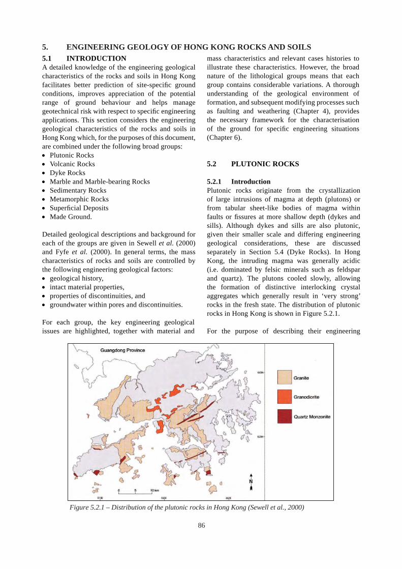
5. ENGINEERING GEOLOGY OF HONG KONG ROCKS AND SOILS 5.1 INTRODUCTION A detailed knowledge of the engineering geological characteristics of the rocks and soils in Hong Kong facilitates better prediction of site-specifi c ground conditions, improves appreciation of the potential range of ground behaviour and helps manage geotechnical risk with respect to specifi c engineering applications. This section considers the engineering geological characteristics of the rocks and soils in Hong Kong which, for the purposes of this document, are combined under the following broad groups: • Plutonic Rocks • Volcanic Rocks • Dyke Rocks • Marble and Marble-bearing Rocks • Sedimentary Rocks • Metamorphic Rocks • Superfi cial Deposits • Made Ground.
Detailed geological descriptions and background for each of the groups are given in Sewell et al. (2000) and Fyfe et al. (2000). In general terms, the mass characteristics of rocks and soils are controlled by the following engineering geological factors: • geological history, • intact material properties, • properties of discontinuities, and • groundwater within pores and discontinuities.
For each group, the key engineering geological issues are highlighted, together with material and
mass characteristics and relevant cases histories to illustrate these characteristics. However, the broad nature of the lithological groups means that each group contains considerable variations. A thorough understanding of the geological environment of formation, and subsequent modifying processes such as faulting and weathering (Chapter 4), provides the necessary framework for the characterisation of the ground for specific engineering situations (Chapter 6).
5.2 PLUTONIC ROCKS
5.2.1 Introduction Plutonic rocks originate from the crystallization of large intrusions of magma at depth (plutons) or from tabular sheet-like bodies of magma within faults or fissures at more shallow depth (dykes and sills). Although dykes and sills are also plutonic, given their smaller scale and differing engineering geological considerations, these are discussed separately in Section 5.4 (Dyke Rocks). In Hong Kong, the intruding magma was generally acidic (i.e. dominated by felsic minerals such as feldspar and quartz). The plutons cooled slowly, allowing the formation of distinctive interlocking crystal aggregates which generally result in ‘very strong’ rocks in the fresh state. The distribution of plutonic rocks in Hong Kong is shown in Figure 5.2.1.
For the purpose of describing their engineering
Figure 5.2.1 – Distribution of the plutonic rocks in Hong Kong (Sewell et al., 2000)
86

geological characteristics, the plutonic rocks can be divided into three main rock types based on their mineralogy (Figure 5.2.2). They collectively occupy about 30% of the land surface area of Hong Kong, but form about 80% of the developed area. The approximate percentages of each of the plutonic rock types in terms of the total area of land formed by plutonic rocks (Figure 5.2.1) are: • Granite (80%) • Granodiorite (15%) • Quartz monzonite (5%).
Granite tends to form circular or ellipsoidal bodies many kilometres across. Granodiorite is more irregular, forming subvertical plutons and laterally persistent sills. Quartz monzonite typically forms smaller stocks and structurally controlled dykes which may be of the order of 50-100 m across.
In general terms, engineering geological considerations largely relate to: • Nature of plutonic rock formation: relatively little
post-formation deformation results in relatively uniform material characteristics over large areas (with the caveats listed below) and interpolation of drillhole information can generally be made with a reasonable degree of confidence.
• Weathering: this is the dominant process which controls the engineering characteristics of plutonic rocks. It is initiated at the surface and penetrates the rock via discontinuities. In the unweathered state, plutonic rocks are very strong to extremely strong and the mass characteristics are controlled by discontinuities.
• Discontinuities: faults, shears, tectonic joints
Figure 5.2.2 – Composition of the plutonic rocks (Sewell et al., 2000)
and stress-relief joints weaken the rock mass and promote irregular weathering where groundwater penetration has occurred.
In specific terms, the key geological factors that may have an adverse influence on the engineering properties of plutonic rocks include: • Contact margin and cooling effects
o heterogeneous and variable material properties (along irregular contact surfaces)
o local variations in material strength o additional discontinuities, i.e. cooling joints
• Material weathering effects o variations in material weathering effects (depth/
rate of chemical weathering and resulting soil properties vary according to mineralogy)
o disintegration (variations in material strength for same weathering grade)
• Mass weathering effects o stress-relief joint development (potentially
affecting slope stability) o development of corestones, coreslabs and
irregular weathering below rockhead (prevalent in coarse-grained rocks, potentially affecting foundations and tunnelling operations)
Table 5.2.1 summarises some material characteristics and properties of the three main plutonic rock types.
5.2.2 Engineering Geological Considerations When magma is emplaced, the surrounding country rocks are partially displaced and partially assimilated into the magma. As a result, blocks of country rock (xenoliths) may occur resulting in irregular contacts and variable material properties.
Concentrations of residual fluids near the margins of cooling plutons can result in greisenisation (alteration, replacement and enrichment of the granite resulting in granular quartz and concentrations of mica and other minerals), and hydrothermal fluids may also penetrate and alter the plutonic and country rocks (e.g. chloritisation). These processes partially alter or replace existing minerals, typically resulting in a reduction in strength through the material fabric or along joint surfaces (Section 4.4). Associated with the final phases of cooling are pegmatites, which are very coarse-grained dykes or veins representing residual portions of the magma. In addition, finegrained veins and dykes of granitic composition (aplite) also occur (see Section 6.7).
87

Granite (Generic) Granodiorite Quartz Monzonite Exposed area in Hong Kong (%)
24 5 1
Occurrence Large circular or ellipsoidal plutons
Tabular sills/dykes or small plutons
Tabular sills
Typical Quartz Composition: Alkali Feldspar ( % )* Plagioclase Feldspar
Biotite mica/Hornblende
35 Abundant quartz 25 25
<10
30 Abundant quartz 10 40 Plagioclase
dominant >10 Relatively
abundant
<20 Little quartz 35 35
<10
Equal feldspars Equal feldspars
Crystalline, with interlocking crystal mosaic. Grain size very fine (aplite) to coarse (pegmatite).
Variations in weathering due to mineralogy, grain size etc. Corestones may occur in saprolite depending on grain size and structure.
More susceptible than granite to weathering due to higher proportion of plagioclase feldspar which is less resistant to chemical weathering than alkali feldspar.
Most susceptible to weathering due to lower quartz content.
Crystalline, with interlocking crystal mosaic. Generally coarse-grained.
Crystalline, with characteristic fabric anisotropy resulting from alignment of tabular alkali feldspar megacrysts.
Range (Acceptable Limit)
Texture and Grain Size General: Reasonably uniform texture, changes may occur especially close to the contact margins.
Material Weathering Properties General: Weathering of granitic rock is generally deeper than volcanic rocks.
Aggregate and Roadstone Properties ACV AIV LAAV TFV (10% Fines Value) (kN)
21-29 (<30) 15-31 (<45) 28-44 (27-44) 100-200 (>50 or>150**)
No specific data 18 12 21.5 No specific data
Suitability for Use in Construction
Good dimension, decorative and armour stone. Good aggregate when fresh. General fill for saprolite.
Good dimension, decorative and armour stone when fresh. General fill for saprolite.
May be used for aggregate (see text). General fill for saprolite.
Excavatability Uniaxial compressive strength (UCS) can be over 250 MPa for fresh rock.
The strength properties for fresh to slightly decomposed rock are similar to granite.
Rock generally requires blasting. Saprolite can be excavated easily by machine although large corestones may require splitting.
Notes: * Some % values are minima ** for heavy duty concrete use
ACV: The aggregate crushing value indicates the ability of an aggregate to resist crushing. The lower the figure the stronger the aggregate, i.e. the greater its ability to resist crushing (BSI,1990a).
AIV: The aggregate impact value indicates the strength value of an aggregate as determined by performing the aggregate impact test (BSI, 1990b).
LAAV: The Los Angeles abrasion value test is carried out to determine the susceptibility of an aggregate to abrasion (ASTM, 2003). TFV: The ten percent fines value test determines the crushing force in kN at which 10% of the weight of aggregate is reduced to fine
material (BSI, 1990c).
!
Table 5.2.1 – Summary of material characteristics and properties for plutonic rocks
Material weathering of plutonic rock is largely a In the fresh state all plutonic rocks are competent, result of chemical decomposition and this in turn but as weathering increases, differences in material is largely a function of the variable stability of the properties become more apparent. The development constituent minerals under the physical conditions of fractures by mechanical disintegration can also to which they have been subjected to over time. reduce the strength of the material (Section 4.4).
88

Mass weathering is largely controlled by the discontinuity characteristics. Weathering along joints leads to an irregular rockhead profile. Plutonic rocks (especially granite) can develop extensive low-angle, undulating stress-relief joints which may be dilated and clay infilled (see Section 5.2.4). Weathering along sub-horizontal joints can result in seams of decomposed rock below the general rockhead and in the formation of coreslabs. Weathering on three or more joint sets can result in corestones within the saprolite matrix and in tors where the saprolite has been eroded. Corestones are more common in coarser grained and more widely jointed plutonic rocks.
5.2.3 Material Characteristics
Rock Composition, Texture and Fabric Plutonic rocks are classified by their composition according to their relative percentages of alkali feldspar, plagioclase feldspar and quartz (Figure 5.2.2). Lesser amounts of other accessory minerals such as biotite and hornblende are also found in these rocks. Differences in the relative proportions of the main component minerals affect the rate of weathering and the properties of the weathered material. Table 5.2.1 shows these differences for the main plutonic rock types and associated material weathering implications.
The mineralogical, textural and fabric changes associated with weathering in some plutonic rocks of Hong Kong have been assessed by Irfan (1996a and 1996b). The key elements and description of the grades of weathering are summarised in Section 4.4 and illustrated in Figure 4.4.4. Visible fractures resulting from weathering appear to be more prevalent within plutonic rocks than in volcanic rocks and are found mostly in Grade IV and (to a lesser extent) Grade V material (Hencher & Martin, 1982).
Granite contains about 35% quartz and roughly equal amounts of plagioclase and alkali feldspar, with minor biotite (Table 5.2.1). This composition together with the interlocking crystal mosaic gives granite a high strength when fresh and a generally sandy soil when fully weathered. The grain size of plutonic rocks is generally uniform over large areas. However, the grain size can vary abruptly, especially near contact margins and this may affect the material properties. Additional fabrics can develop due to flow prior to cooling. This results in preferred orientations of mineral grains (schlieren).
Granodiorite also has a high strength when fresh, and contains about the same or slightly lower quartz content as granite but has a much higher proportion of plagioclase feldspar. This can result in a higher fines content upon weathering, relative to granite, as plagioclase is more susceptible to chemical weathering than alkali feldspar. Consequently, there is a more pronounced reduction in strength with decomposition, and a generally greater depth of weathering when compared to granite.
Quartz monzonite has significantly less quartz than granite or granodiorite (<20%) and is, therefore, the most susceptible to chemical weathering. Compared to completely decomposed granite, this may result in a material with a relatively high clay content, greater extent of penetrative weathering and with different material properties. These characteristics can have adverse engineering implications, e.g. at the Aberdeen Tunnel South Portal (Twist & Tonge, 1979). However, in the fresh state the rock is a competent material.
Material Properties There is a significantly larger amount of numerical test data available for granite in comparison to granodiorite and quartz monzonite due to the greater surface exposure of granite within Hong Kong, especially in the urban areas. Plutonic rocks generally have very good material properties for engineering purposes, when in the fresh state. However, the degree, depth and rate of weathering of plutonic rock material is strongly influenced by the mineralogy as indicated above.
Plutonic rock masses can also be locally weakened at depth by hydrothermal alteration, especially near the margins of plutons and along fault zones (Section 4.3). This generally has more signifi cance to deep foundations and tunnel excavations (Chapter 6), but also may affect slope stability.
Radon occurs naturally in many geological environments and is particularly associated with granitic rocks as a result of their relatively high uranium content (Sewell, 1999). Radon can be a radiation hazard if concentrations of the gas and its decay products exceed safety limits (Ball et al., 1991). Further information and references relating to the occurrence and control of radon gas in tunnels and caverns are given in Section 6.7.
89

Rock Properties Typically fresh granite, Grade I, is very strong to extremely strong, with uniaxial compressive strength (UCS) about 200 MPa. Grade II granite, slightly decomposed, is very strong, with UCS about 100 to 150 MPa. Grade III granite, moderately decomposed, is moderately weak to strong, with UCS about 10 to 80 MPa. Grade IV granite is weak when it is intact but is classified as a soil when highly fractured and composed of loosely interlocking fragments. However, within these decomposition grades wide variations in strength occur due to the gradational nature of rock decomposition and variability in the degree of microfracturing.
There are fewer test results readily available for granodiorite and quartz monzonite rocks. However, Irfan & Powell (1984) indicate a range of UCS between 150 MPa and 200 MPa for fresh Tai Po Granodiorite, and Irfan (1987) indicates a maximum UCS of about 300 MPa for quartz monzonite from Turret Hill quarry. These results indicate that in the fresh and slightly decomposed state the material strength properties of the plutonic rocks are similar (i.e. very strong to extremely strong).
Soil Properties Saprolite is a soil derived from the in situ weathering of rock. It retains the relict structure and texture of the rock mass and typically comprises decomposition Grade V but may include Grade IV where it is disintegrated to gravel or sand. As a result of the breakdown of feldspars and the abundant more resistant quartz, granite saprolite typically forms a sandy silt when completely decomposed. However, variations do occur. Figure 4.4.4 in Section 4.4.3 summarises the chemical decomposition process in granitic rock. This demonstrates how variations in the proportions of the main component minerals affect the derived saprolite material. Saprolites derived from granodiorite and quartz monzonite tend to result in sandy clay and slightly sandy silty clay respectively. However, there can be considerable variability in density and strength, even within the same rock type and the same decomposition grade.
Table 4.4.2 (see Section 4.4.3) gives ranges of engineering properties within a completely decomposed granite profile at the ‘strong’ and ‘weak’ ends of the completely decomposed grade. There are significant variations in engineering properties due to differences in lithology, alteration, and moisture
conditions at different sites. Therefore, representative engineering properties can only be obtained through site-specific investigations. However, the example serves to highlight that where a thick zone of saprolite occurs, it may be feasible to sub-divide it for the purposes of geotechnical characterisation, provided that the boundaries between the different zones can be reliably depicted in the geological model.
The plasticity of granite saprolite is usually in the low to intermediate range. However, saprolites derived from granodiorite, monzonite and altered granite may develop a higher plasticity, falling within the intermediate and occasionally high plasticity zones, due to mineralogical variations. Similarly, the permeability of saprolite soils will be affected by the mineralogy and the fi nes/sand content.
5.2.4 Mass Characteristics The mass characteristics of plutonic rocks are largely dependent on the nature, persistence and density of discontinuities and the degree of weathering.
Discontinuities General Discontinuities allow inelastic deformation of the rock mass and can reduce mass strength by more than an order of magnitude, depending on confi ning stress (Hoek, 2004). The following discontinuity types are especially pertinent to plutonic rocks: • Cooling joints • Tectonic joints • Stress-relief joints
In addition to their effect on the rock mass, these joints can result in variable and steeply sloping rockhead and allow weathering below general rockhead. Variable and steeply sloping rockhead can be problematic for piling (see Section 6.5), and weathering below rockhead can be problematic for tunnelling (see Section 6.7).
In general, plutonic rocks tend to have wider spaced discontinuities than volcanic rocks. On a site-specific scale, the plutonic rocks typically contain a low-angle joint set and two orthogonal joint sets that are normally steeply-inclined. However, additional sets are commonly present, which may be inclined in the range of about 30° to 90° (see Figure 4.2.6). These sets can be important for the stability of steep rock slopes, since they may form potential failure planes that are too steeply-inclined for joint roughness to
90

provide adequate shearing resistance (see the Ting Kau Cutting case study in Section 6.4.4 for example). Different plutonic intrusions may have a different joint pattern to the adjoining plutons.
Cooling Joints Due to the nature of plutonic rocks, primary discontinuities usually form during the late cooling stages of the magma. Four main types occur and are defined in terms of their relation to fl ow structures (flow lines sub-parallel to the edge of the pluton occurring during emplacement), namely cross-joints, longitudinal joints, diagonal joints and flat lying joints (Price, 1966). The identification of such features can be problematic, especially when flow lines are absent. However, veins and mineralization may be associated with these joints. The stress systems that formed these structures may influence the formation of later tectonic and stress-relief discontinuities. Gamon & Finn (1984) identified an additional steeply dipping cooling joint set within granite occurring close to (within 150 m) and parallel to a geological contact, during a major site formation.
Tectonic Joints Tectonic structures including tectonic joints and faults reflect responses of the rock mass to changes in stress regimes due to tectonic processes. These processes are discussed in Section 4.2. Faults and fault-related joints can be very persistent and can promote deep weathering resulting in linear rockhead depressions.
Stress-relief Joints Stress-relief joints form when a pluton is unloaded due to erosion. Moderately inclined stress-relief joints, sub-parallel to the ground surface are also commonly known as sheeting joints. Adjacent to steep terrain with relatively rapid rates of erosion such as active coastal settings or fault controlled valleys (or large man-made excavations), stress relief can also act laterally, thereby inducing formation and subsequent dilation of relatively steeply-dipping joints.
The spacing of stress-relief joints within plutonic rocks is variable. On a small scale, stress-relief and microfracturing can result in extremely closely spaced joints (Figure 4.4.1). Persistent stress-relief joints are typically widely spaced, but with increasing depth the spacing may increase to extremely widely-spaced as the influence of the stress-relief effects diminish. The persistence of stress-relief joints within the plutonic rocks has been recorded extending over hundreds of
metres at some coastal sites.
The aperture of stress-relief joints also tends to decrease with depth due to a reduction in stress-relief effects. Observations made after the Lei Pui Street landslide (MGSL, 2004), which failed along a stress-relief joint, revealed apertures of over 100 mm exposed along the flanks of the landslide source area. Drillholes at the same site also indicated that the stress-relief joint apertures were <10 mm below 10 m depth at this particular location.
At low stresses, given the wavy nature of stress-relief joints, the roughness angle of the discontinuity is important due to its effect of increasing the overall friction angle. However, extreme waviness can result in localised steep inclinations, which can induce failure, (e.g. at Hiu Ming Street – see Section 6.4.3).
Richards & Cowland (1982) report that the roughness angles of stress-relief joints at North Point varied from 16° to 6°. For design, two roughness angles were adopted: 16° where stress-relief joints were persistent and potentially affected the entire lower slope, and 8° for small potential failures affected by near surface joints. Richards & Cowland (1982) note that these are site-specific measurements which should not be adopted elsewhere without fi eld verification.
Where shear box testing of a joint is undertaken the natural roughness of the surfaces should be taken into account by normalising the data to account for dilation during testing (Hencher & Richards, 1982). A basic friction angle of 40° has been proposed by Hencher & Richards (1982) regardless of the decomposition grades. The roughness of stress-relief joints and their effect on friction angle has been assessed at a number of landslide failures within granite rock masses including at Lei Pui Street (MGSL, 2004) and Leung King Estate (HCL, 2001).
Dilation of stress-relief joints can reduce rock-torock contact and thus shear strength. Water pressure build-up in near-surface stress-relief joints can also adversely affect stability. Failure along wavy surfaces characteristic of stress-relief joints requires considerable dilation of the rock mass. In some cases, incremental movement and dilation of the rock mass may occur due to transient build-up of water pressure without immediate failure occurring. Subsequent infilling of discontinuities may impair groundwater flow, increasing basal water pressures during heavy
91

rainfall and thus promoting further downslope movement. The cycle is repeated until the system stabilises or failure occurs (Hencher, 2006).
Cowland & Richards (1985) discuss the contribution of persistent sheeting joints to rapid transient groundwater rise in the granite hillside above North Point. They also conclude that at this particular site transient groundwater rises did not occur simultaneously over the entire surface area of the joints, thus producing less severe groundwater conditions than normal assumptions of a rising groundwater table would indicate (see Section 4.6.4). This phenomenon may have been influenced by a combination of partial infilling, constrictions and free-draining pathways along the joint surfaces.
Case Study - Leung King Estate Landslide Sheeting joints which were wavy, dilated and infilled were observed to form the surface of rupture of a landslide during the investigation of the natural terrain landslides above Leung King Estate in 2000 (HCL, 2001). The nature of the sheeting joints, block displacements and sediment infilling are shown in Figure 5.2.3. These observations indicate that progressive movements of the rock slabs above the joint surfaces had occurred. Theoretical back
analysis of the failure indicated that the range of operative friction angle for the wavy sheeting joint was between 33° and 60° for a groundwater head range of between 0 m and 3 m.
Rock Mass Weathering Rock mass weathering processes in granitic and volcanic rocks are described in Section 4.4. In comparison with the volcanic rocks, the depth of the weathered profile of the plutonic rocks is typically greater.
Material Uses Fresh granite is a source of concrete aggregate and roadstone, decorative and armour stone and rock fill. Most aggregates used in Hong Kong are sourced from granite due to its abundance and its material properties which are within the acceptable limits for aggregates used in concrete and roadstone production (Table 5.2.1). These favourable material properties are related to the interlocking, crystalline nature of the fresh rock with abundant resistant quartz and feldspar. Some medium- and coarse-grained granites have an Aggregate Impact Value (AIV), Aggregate Crushing Value (ACV) or Abrasion Value on the higher side of acceptable limits, making them less desirable compared to fine-grained granites for
Figure 5.2.3 – Failure along wavy stress relief joint surface in Tsing Shan granite (after HCL, 2001)
Clay infill in dilated stress -relief joints
Approximately 25 mm sub-vertical displacement of joint
Minor seepage noted on sheeting joint on 24.10.2000, four days after a heavy rainstorm
20 mm thick clay infill - soft to firm light brown clay with occasional sand grains
Approximately 5 mm sub-horizontal displacement of sheeting joint (note trailing corner has fractured)
0 0.1 0.2 m Approximate scale
Clay infillRock on rock
Rock on
rock
General direction of downslope movement
Clay infill
Offset joints
92

wearing courses and some special uses such as heavy duty concrete floors. Low crushing strength may arise due to fracturing along the cleavage planes of coarse crystalline constituents. Problematic materials can also occur in shear zones, hydrothermally altered veins and aplite dykes.
Quartz monzonite when fresh has comparable mechanical and physical aggregate properties to granite and is generally within the acceptable limits for use in concrete and roadstone production (Irfan, 1987). However, quartz monzonite aggregates may have a lower resistance to abrasion due to lower free silica (quartz) content. Quartz monzonite also contains a higher percentage of feldspars compared to granites and is likely to be more susceptible to further decomposition and disintegration if the rock has already undergone some weathering. In addition, the alkali feldspars often display a preferred orientation, with less crystal intergrowth or interlocking, which may affect the mechanical properties parallel to the preferred orientation of the crystal fabric.
Granodiorite has not been exploited as a source of aggregate in Hong Kong. Although aggregate test data are lacking, fresh granodiorite is probably suitable for concrete aggregate and roadstone. Fresh quartz monzonite and granodiorite are also suitable for armour stone and rock fi ll. Alkali aggregate reaction is generally not problematic except where the rock has been altered.
Saprolite from plutonic rocks is generally suitable as earth fi ll material.
5.3 VOLCANIC ROCKS
5.3.1 Introduction During the Middle Jurassic to Early Cretaceous periods, intense regional volcanic activity affected the Hong Kong area. This resulted in deposits of pyroclastic rocks (mostly rhyolitic tuff) up to several thousand metres thick, and lesser lava fl ows. The volcanic rocks collectively occupy about 50% of the land surface area, much of it forming hilly terrain.
During periods of volcanic activity, some of the volcanic material was re-worked by water to form sedimentary rocks. Consequently, the volcanic rocks contain beds of sedimentary rock which vary in grain size, thickness and extent. Furthermore, the volcanic
activity was often contemporaneous with the intrusion of the plutonic rocks (see Section 5.2). As a result, metamorphism and deformation are evident in some volcanic rocks and may affect the material properties (see Sections 4.2.3 and 4.3.2).
The key engineering geological considerations for volcanic rocks relate to their origin and postdepositional deformation, leading to potential variability in the following characteristics: • Composition • Grain size • Fabric • Discontinuities • Strength
Compared to the plutonic rocks, the material and mass properties of the volcanic rocks are generally more variable and this variability is exacerbated by weathering.
A detailed account of the volcanic rocks is given in Sewell et al. (2000). Most volcanic rocks in Hong Kong comprise tuffs of varying age, which forms the basis for their stratigraphical grouping. However, for the purposes of describing their engineering geological characteristics the tuffs are considered as a single rock type in this document.
In addition to tuff, subordinate lavas occur. These vary from rhyolite to dacite and trachydacite to andesite in composition. With the exception of the andesite lava, which has some unique engineering geological characteristics, there is little engineering information on the lavas given their geographical locations in relatively remote areas. Other volcanic rocks which are much less extensive, but which also justify their separate consideration due to distinctive engineering geological characteristics, are: • Marble-bearing volcaniclastic rock. • Tuffaceous sedimentary rocks.
The distribution of the volcanic rocks is shown in Figure 5.3.1. Details of the material and mass properties of these rocks are given in Sections 5.3.3 and 5.3.4, and summarised in Table 5.3.1.
5.3.2 Engineering Geological Considerations
Tuff In the fresh state, tuff is typically much stronger (extremely strong with UCS up to 400 MPa) and
93

more abrasive than granite. This high strength can affect drillability and the performance of tunnel boring machines (TBM).
Tuffs also typically have closer joint spacing than granite but variations occur with grain size. Fine ash tuff tends to have closely spaced joints resulting in a blocky, angular rock mass. Coarse ash tuff tends to have wider spaced joints and can exhibit corestone development when weathered. Columnar jointing occurs in the fine ash tuffs of the High Island Formation.
Lava The engineering geological characteristics of rhyolite lava (silica-rich) are similar to rhyolitic tuff. However, andesite lava of the Tuen Mun Formation has a mafic-rich mineralogy and is susceptible to deep weathering and usually forms a silt-rich soil. It also has relatively low shear strength when completely decomposed, reaching very low residual shear strength where previous movement has occurred (Section 5.3.6).
Tuff-related Rocks Tuffaceous sedimentary rocks (e.g. Lai Chi Chong and Mang Kung Uk Formations) have similar engineering geological characteristics to sedimentary rocks (Section 5.6) which vary depending on the strength and composition of the clasts and the matrix, and on the spacing and continuity of the bedding. Minor sedimentary units also occur as interbeds within the main tuff sequences.
The main engineering geological characteristic of marble-bearing volcaniclastic rock (Tin Shui Wai Member, Tuen Mun Formation) is dissolution weathering of the marble clasts which is discussed in Section 5.5.
5.3.3 Tuff Material Characteristics
Rock Composition, Texture and Fabric Tuffs are classified by a combination of grain size and composition of constituent fragments (Figure 5.3.2). The grain sizes are: • fine ash (<0.06 mm)
Principal lithological types: Columnar jointed tuff Tuffaceous sedimentary rock
Mostly tuffs Andesite
Figure 5.3.1 – Distribution of the volcanic rocks in Hong Kong (after Sewell et al., 2000)
94

Lith
olog
y Tu
ff Vo
lcan
icla
stic
Roc
ks
And
esite
Lav
aSu
b-Ty
pe
Fine
Ash
Tuf
f C
oars
e A
sh T
uff
Euta
xite
Gen
eral
Cha
ract
eris
tics
Tuff
and
rhyo
lite
lava
have
ahi
gher
SiO
2 co
nten
t (fe
lsic
min
eral
s) a
nd a
re m
ore
resi
stan
t to
wea
ther
ing
than
and
esiti
c (in
term
edia
te) r
ocks
.Li
mite
d in
form
atio
n on
rhyo
lite
lava
but
like
ly to
hav
e si
mila
r pro
perti
es to
fine
ash
tuff
and
is s
trong
ly fl
ow b
ande
d.Vo
lcan
ic ro
cks
are
gene
rally
less
dee
ply
wea
ther
ed th
an p
luto
nic
rock
s an
d ar
e ty
pica
lly m
uch
stro
nger
and
abr
asiv
e th
an p
luto
nic
rock
s w
hen
fresh
.Tu
ff an
d la
va a
re e
xtre
mel
y st
rong
whe
n fre
sh. V
olca
nicl
astic
rock
s ha
ve a
wid
e ra
nge
in s
treng
th, b
ut m
ay b
e ex
trem
ely
stro
ng w
here
alte
red
by c
onta
ct m
etam
orph
ism
.D
isco
ntin
uitie
sTy
pica
lly c
lose
ly jo
inte
d gi
ving
abl
ocky
rock
mas
s. M
ay c
onta
inse
dim
enta
ry u
nits
. Hig
h Is
land
Form
atio
n ha
s w
ell d
evel
oped
colu
mna
r joi
ntin
g.
Typi
cally
wid
er jo
int s
paci
ng th
an fi
ne a
sh tu
ff.M
ay c
onta
in s
edim
enta
ry u
nits
. W
elde
d an
d fla
ttene
d fra
gmen
ts(fi
amm
e) in
dica
te b
eddi
ng.
Com
mon
ly b
edde
d.
Ande
site
con
tain
s lit
tle o
r no
prim
ary
inte
rnal
stru
ctur
e.
Wea
ther
ing
Wea
ther
ed le
ss d
eepl
y th
anco
arse
ash
tuff
(typi
cally
<15
m),
rare
ly d
evel
ops
core
ston
es.
Typi
cally
form
s a
clay
/silt
sapr
olite
.
Mod
erat
ely
thic
k w
eath
ered
pro
files
(up
to 3
5 m
)an
d co
rest
ones
pre
sent
. Typ
ical
ly fo
rms
a si
lt or
silty
san
d sa
prol
ite.
Wea
ther
ed le
ss d
eepl
y th
anco
arse
ash
tuff,
rare
ly d
evel
ops
core
ston
es.
Gen
eral
ly m
ore
deep
lyw
eath
ered
than
tuff.
If li
thic
fragm
ents
are
pre
sent
they
may
wea
ther
diff
eren
tially
espe
cial
ly if
car
bona
te-ri
ch.
Hig
h m
afic
min
eral
con
tent
resu
lts in
dee
p w
eath
erin
g(>
20 m
) and
a c
laye
y si
ltsa
prol
ite.
Gra
in S
ize
Very
fine
-gra
ined
/ gl
assy
mat
rix.
Mai
nly
com
pose
d of
cry
stal
s an
d sc
atte
red
a ngu
lar c
last
s of
vol
cani
c ro
ck.
-gra
ined
gla
ssy
mat
rix.
Very
fine
Wid
e ra
nge
of g
rain
siz
esfro
m fi
ne g
rain
edm
udst
ones
to c
oars
eco
nglo
mer
ates
.
Fine
-gra
ined
mat
rix.
Agg
rega
te a
ndR
oads
tone
Prop
ertie
s R
ange
(A
ccep
tabl
e Li
mit)
ACV
AIV
LAAV
10%
Fin
es (k
N)
(see
Tab
le 5
.2.1
for d
efin
ition
)
10-1
8
9-2
113
-22
200-
335
(<30
)(<
45)
(<40
)(>
50)
Insu
ffici
ent d
ata.
Suita
bilit
y fo
rU
s e in
Con
stru
ctio
n
Mos
t tuf
fs a
re s
uita
ble
as a
ggre
gate
for c
oncr
ete
and
road
ston
e w
hen
in th
e fre
sh s
tate
, but
see
Sec
tion
5.3.
5re
gard
ing
unifo
rmity
and
alk
ali a
ggre
gate
reac
tivity
con
side
ratio
ns. S
uita
ble
for r
ockf
ill an
d ar
mou
r sto
ne w
hen
fresh
.
Gen
eral
ly n
ot s
uita
ble
asag
greg
ate
or ro
ckfil
l due
tova
riabi
lity.
Insu
ffici
ent d
ata
on s
uita
bilit
yas
agg
rega
te. S
uita
ble
asro
ckfil
l whe
n fre
sh.
Mos
t vol
cani
c ro
cks
are
suita
ble
as g
ener
al fi
ll in
the
wea
ther
ed s
tate
.Ex
cava
tabi
lity
Roc
k ge
nera
lly re
quire
s bl
astin
g. S
apro
lite
can
be e
xcav
ated
eas
ily b
y m
achi
ne. L
arge
cor
esto
nes
may
be
enco
unte
red
in c
oars
e as
h tu
ff an
d m
ay re
quire
spl
ittin
g.
Tabl
e 5.
3.1
– Su
mm
ary
of m
ater
ial c
hara
cter
istic
s and
pro
pert
ies f
or v
olca
nic
rock
s
95

• coarse ash (0.06-2 mm) • lapilli (2-60 mm) • blocks and bombs (>60 mm).
The constituent fragments generally comprise crystal fragments (crystal tuff), rock fragments (lithic tuff) or pumice/glass fragments (vitric tuff).
The tuffs are mostly rhyolitic in composition (i.e. similar in composition to granite) and therefore consist primarily of quartz, feldspar and subordinate mafic minerals (e.g. biotite), set in a microcrystalline (quartz and feldspar) to vitric (glassy) matrix. Tuffs tend to be more resistant than the plutonic rocks, forming much of the mountainous terrain in Hong Kong.
The most common fabric within the tuffs are welding fabrics, where original glassy shards were aligned, fused and re-crystallised. This results in a fabric referred to as eutaxitic foliation which refl ects the original orientation of deposition. The changes in orientation of eutaxite at the Shum Wan Road landslide suggested that faulting might have controlled the deeper weathering at the landslide location (Kirk et al., 1997). A clay-rich zone in tuff, parallel to the eutaxitic foliation was identified as a major influence of the Fei Tsui Road landslide (GEO, 1996a,b).
Relatively thin layers of tuffaceous sedimentary rocks are irregularly distributed within the tuffs. Volcanic rock formations with a significant sedimentary rock component are discussed separately in Section 5.3.7.
Figure 5.3.2 – Classification of pyroclastic rocks (after Schmid, 1981 and Fisher & Schminke, 1984)
Blocks and bombs >60 mm
Ash <2 mm
(coarse 0.06-2 mm) (fine <0.06 mm)
Lapilli 2-60 mm
PYROCLASTIC BRECCIA,
AGGLOMERATE
Material Properties As with other volcanic rocks, the main factor that causes variability in the material properties of tuffs is weathering, in particular chemical decomposition. The degree, depth and rate of weathering of tuff is strongly influenced by both the rock material properties, such as mineralogy, as well as mass properties discussed later in this section. Weathering is discussed in general in Section 4.4. However, the following reflects specific weathering characteristics related to the tuffs.
The decomposition of volcanic rocks generally results in a finer-grained soil than in the plutonic rocks due to the fine microcrystalline matrix which is most pronounced in the fine-grained tuffs (see soil properties). Microfracturing is generally less extensive than in the plutonic rocks. This may be due to the finer grain size and much shallower level of rock formation (resulting in less susceptibility to microcracking related to stress relief) or possibly due to the effects of stress relief being absorbed by the closer jointing (see Section 5.3.4). However, the rocks still exhibit some increase in microfracturing with increasing decomposition grade.
Rock Properties The properties of tuffs vary considerably depending on the rock type and the degree of weathering and of disintegration (Table 5.3.1). Fresh and slightly decomposed rock, Grades I and II, are very strong to extremely strong. UCS values can be above 300 MPa and such rocks can be hard and abrasive. The finer-grained tuffs tend to be the strongest. High rock strength can be an important issue in some engineering applications, such as tunnel excavation by TBM, as cutter wear is an important economic and technical factor. For Grade III the UCS values drop off to below 50 MPa and for Grade III/IV rock the values are less than 25 MPa. Grade IV tuff is weak when intact but is very often disintegrated due to weathering. In such cases, the rock may be broken down by hand to gravel and smaller sizes and may then be described a soil.
Soil Properties Saprolite derived from fine ash tuff typically forms a clay/silt when completely decomposed as a result of the breakdown of the constituent grains and the fine matrix containing microcrystalline feldspar and quartz. In coarse ash tuff, the matrix is coarser grained, and silt or sandy silt soil may result.
96

The fine portion of a soil has a significant effect on the engineering properties. Within the tuffs there can be considerable variability due to lithological variations. The fines content of completely decomposed fi ne ash tuff has a wide range from 30% to 90%. For coarse ash tuff the range is smaller, typically 50% to 80%, reflecting the nature of the constituent coarse grains.
Fine-grained tuff saprolite is usually in the intermediate plasticity range due to the high proportion of clay weathering products. Variations in plasticity within the tuffs generally relate to variations in chemical composition and degree of weathering.
Saprolites derived from volcanic rocks generally have a relatively high percentage of fines and low intact material shear strength parameters compared to saprolites derived from plutonic rocks. However, there can be considerable variability in density and strength, even within the same rock type and the same decomposition grade.
5.3.4 Tuff Mass Characteristics The mass characteristics of tuffs depend largely on: • nature, persistence and spacing of discontinuities,
and • degree of weathering.
Discontinuities General In general terms, the tuffs tend to have closer spaced discontinuities than the plutonic rocks, especially within fine-ash tuff where the joint spacing is relatively close with typically four major joint sets defining angular blocks (see Table 5.3.1).
Stress-relief or sheeting joints occur in tuffs but are generally less persistent than those in plutonic rock (see Section 5.2.4).
Columnar jointed tuff Columnar cooling joints are characteristic of the High Island Formation which comprises massive, fine ash vitric tuff in the Sai Kung and Clearwater Bay areas. Columnar cooling joints typically form perpendicular to the plane of deposition so the High Island cooling joints are steeply dipping to sub-vertical and are observed to be up to 30 m in height (Sewell et al., 2000). Little engineering data is available for these rocks as they are remote from developed areas. However, the engineering geology of the faulted and intruded rocks underlying the High
Island Reservoir dam foundations and some of the associated construction difficulties are described in Watkins (1979) and Vail et al. (1976) respectively (see Section 6.5.3). Structurally controlled instability is also common in this rock type (Campbell et al., 1999).
Rock Mass Weathering The weathering profi le in fine ash tuff is generally thinner (typically less than 15 m) in comparison to the plutonic rocks. However, in coarse ash tuffs weathering profiles of up to 35 m can develop (Irfan, 1998a). A transitional weathering profile with corestone development is only common in coarse ash tuff. Sharp soil to rock interfaces are more characteristic of fine ash tuff (Figure 4.4.5). Laterally persistent clay can accumulate along planar interfaces such as joints and sheared zones (see the Fei Tsui Road example in Section 6.4.4).
5.3.5 Tuff Material Uses Most tuffs are mechanically superior to typical granite equivalents and can provide suitable concrete aggregates from both mechanical and physical property viewpoints (Burnett, 1989). From Table 5.3.1 it can be seen that the aggregates produced from fresh tuffs are typically within the acceptance limits for use in concrete and roadstone production. Kwan et al. (1995), indicate that aggregates derived from tuff can be more suitable for making high strength concrete than aggregates derived from plutonic rocks. Durability is generally very favourable and well within the soundness criteria (Irfan, 1998a). Tuff is also generally suitable for armour stone and rock fill.
A negative characteristic that can detract from the use of tuffs as aggregates is that bedded tuff rock masses can be heterogeneous and variations in lithology and physical properties can occur over short distances. As approved concrete and asphalt mix designs require uniformity of the aggregate, the geological variations within any prospective site need to be well understood to allow the suitable strata to be selectively extracted. For these reasons, relatively uniform and thickly-bedded coarse ash tuff is more favourable for quarrying.
A study of the alkali aggregate reactivity (AAR) potential of tuff aggregates from the Anderson Road Quarry indicated that they were “potentially reactive” (Leung et al., 1995). The reactive component is
97

generally microcrystalline and cryptocrystalline (glassy) quartz, which is found mainly in the fi ne ash and vitric tuffs. However, the AAR potential can be controlled with the addition of pulverised fuel ash (PFA) in the concrete mix. Chak & Chan (2005) give a review on prevention of alkali silica reaction which is the main form of AAR in Hong Kong.
The saprolitic soils resulting from the decomposition of tuffs are generally suitable as earth fi ll material.
5.3.6 Lava Lavas typically have a fine-grained matrix whose individual crystals cannot be seen by the naked eye. These rocks are sometimes porphyritic, containing large individual crystals within the fine matrix. Although rhyolite lava is more common than other types, it is also more geographically remote and there is little engineering data on its properties. However, due to its rhyolitic composition, it is likely to have similar material properties to the tuffs.
In comparison, andesite lava within the Tuen Mun Formation presents significant engineering problems. The andesite lavas are intermediate in composition, i.e. they are quartz deficient and relatively rich in ferromagnesian minerals which makes them more prone to chemical decomposition.
Completely decomposed andesite is typically a firm to stiff, becoming very stiff with depth, greenish grey, slightly clayey silt. A summary of peak and residual shear strength values is given by Koor et al. (2000). The shear strength generally increases with depth, with typical peak values of c′ = 6 kPa and φ′ = 32° within the uppermost 10 m. Typical index properties for completely decomposed andesite are shown in Table 5.3.2.
Taylor & Hearn (2000) indicate that the uppermost 5 to 10 m of the andesite saprolite in Area 19, Tuen Mun, is intensely weathered with a marked increase in plasticity and fi nes content. This probably reflects almost complete decomposition of the feldspars and mafic minerals such as hornblende and pyroxene.
Liquid Limit (%)
Plasticity Index (%)
Moisture Content (%)
Clay Content (%)
Silt Content (%)
42-63 11-26 19-48 2-11 80-90
Table 5.3.2 - Index properties of completely decomposed andesite (Koor et al., 2000)
The relict joints within the completely decomposed andesite are commonly slickensided, typically with manganese oxide staining and thin films of clay. In Area 19 (see case history in Section 6.3), low-angle, large-scale shear surfaces which typically contain soft to firm grey remoulded clay are associated with large instabilities.
Shear box testing and back analyses of failures in Area 19 indicate that the residual friction angle of the shear planes generally varies from 9° to 17°, with c′ = 0 (Koor et al., 2000). Given such low residual strength, there is a possibility that very low friction clay minerals may be present in the shear plane infills.
Owing to its high silt content, the completely decomposed andesite is highly susceptible to erosion and softening by surface water. This can lead to the extensive development of pipes and deep gullies which typically exploit steeply dipping relict joints striking down slope.
A large-scale, very slow moving natural terrain landslide has been reported in andesite to the south of Leung King Estate (Parry & Campbell, 2003). This landslide involves approximately 40,000 m3
of predominantly colluvial material which is gradually moving down slope on basal shear planes developed at or just below the colluvium/completely decomposed andesite interface. The landslide is a complex, probably very old feature with fresh, well developed lateral tension cracks. The overall angle of the surface of the landslide material is approximately 15°, and about 85 mm of cumulative downslope movement was recorded by an inclinometer over a period of 12 months (Parry & Campbell, 2003).
The previous instabilities affecting man-made slopes in Area 19, and the occurrence of large-scale natural terrain landslides associated with andesite, indicate that caution should be exercised when planning site formations in this material, particularly where high base groundwater levels and perched groundwater tables are suspected (see Section 6.3).
5.3.7 Other Volcanic Rocks
Tuffaceous Sedimentary Rocks Sedimentary rocks have a variable range of grain size, depending on the depositional environment. The rocks range from fine-grained mudstones to
98

coarse-grained conglomerates. The classification of tuffaceous sedimentary rocks is similar to that for sedimentary rocks (Section 5.6). Volcanic rock formations in Hong Kong which contain significant sedimentary units include the Mang Kung Uk Formation (Figure 5.3.3) and the Lai Chi Chong Formation. The remoteness of these formations (Figure 5.3.1) means that little geotechnical data are available, although detailed geological descriptions of the two formations are given in Sewell et al. (2000). Minor sedimentary units also occur within the more massive tuff units.
Due to the variable mode of formation and the heterogeneous, interbedded nature of these rocks, lateral and vertical changes in rock lithology may occur with implications for the engineering properties.
Bedding may affect the engineering properties of tuffaceous sedimentary rocks by forming planes of weakness and making them more susceptible to differential weathering. In closely-bedded sequences of varying lithology (and weathering properties), a heterogeneous rock mass may be formed consisting of alternating relatively unweathered and weathered beds (Figure 5.3.3).
Bedding structures may act as weakness planes
Different rock lithologies may weather preferentially
Figure 5.3.3 – Bedded tuffaceous sedimentary rocks with variable grain size (conglomerate, sandstone, siltstone and mudstone) in the Mang Kung Uk Formation (Sewell et al., 2000)
Marble-bearing Rock Marble-bearing breccia in the Tin Shui Wai Member, Tuen Mun Formation occurs in discrete layers within the volcaniclastic succession. The marble clasts are relatively small and dissolution of the clasts is likely to be local and limited in scale (see Section 5.5).
5.4 DYKE ROCKS
5.4.1 Introduction Dykes are minor intrusive igneous rocks that are typically sub-vertical and of limited thickness (i.e. a few centimetres to tens of metres wide). Sills (gently-inclined sheet-like intrusions) also occur but are generally minor. Since the engineering effects of sills are similar to dykes, where they are of similar thickness and composition, sills can be regarded as ‘dyke rocks’ for the purposes of this document. Dykes can have considerable lateral and vertical extent and may be composite in nature, varying in grain size and composition. Dykes occur throughout most of Hong Kong, either singly or in groups (dyke swarms).
A detailed description of dyke rocks is given in Sewell et al. (2000). However, in engineering geological terms, the dyke rocks of Hong Kong can be divided into silica-rich (rhyolitic) and silica-poor (mafic).
The key engineering geological issues with dyke rocks mainly relate to differences in mass and material properties between the dyke and the surrounding host rock, the effects of the intrusion of the dyke on the host rock and the effect of differential weathering between the dyke and the host rock (country rock).
5.4.2 Engineering Geological Considerations The contact margins between a dyke and the host rock may result in abrupt changes in material characteristics and discontinuity characteristics. Fractured zones can occur along the chilled contact margins with consequent poor rock mass properties and higher permeability (see Section 6.7.3). However, delineating contact margins over large areas from drillholes can be difficult as the contacts can vary from planar to highly irregular.
The weathering of dyke rocks is controlled mainly by their mineralogical composition and discontinuity frequency, spacing and persistence. Consequently, dykes may weather preferentially or be more resistant than the surrounding country rock. Mafic dykes
99

readily weather to clay-rich soils (Au, 1986) whereas rhyolitic dykes are generally resistant to weathering.
Resistant rhyolitic dykes traversing hillsides may form positive topographic linear features resulting in areas of over-steepened terrain immediately downslope (see the Lai Cho Road case study in Section 5.4.6). Completely decomposed mafi c dykes may act as aquitards (see the Tuen Mun Highway case study in Section 5.4.6). The 300 m3 failure at the 14½ Milestone on Castle Peak Road in 1994 is another example of weathered mafic dykes affecting the hydrogeology (Franks, 1995; Chan et al., 1996b).
Mafic dykes may preferentially weather for several tens of metres below the surrounding country rocks resulting in uneven rockhead levels. Given their commonly sub-vertical nature, weathered dykes may not be encountered during a ground investigation but may significantly affect subsequent works.
5.4.3 Origin and Occurrence of the Dyke Rocks Rhyolite is granitic in composition with a grain size <0.06 mm. Rhylolitic dykes can be subdivided into feldsparphyric and quartzphyric, depending on the nature of contained phenocrysts. Feldsparphyric rhyolite dykes are the most common type and are mainly concentrated in a large dyke swarm on the northeast of Lantau Island, although they do occur elsewhere as single features. Quartzphyric dykes are located throughout Hong Kong, including part of the Lantau dyke swarm. Elsewhere, they form smaller swarms or single features.
Mafic dykes are basaltic in composition and are widespread throughout Hong Kong. They generally occur as narrow (<1 m thick) dykes (Sewell et al., 2000), but may also be found occasionally up to 6 m wide or as small stocks (Sewell, 1992).
5.4.4 Material Characteristics
Feldsparphyric Rhyolite Many of the smaller dykes (<5 m wide) are relatively uniform in grain size and texture. However, the larger dykes commonly grade internally from rhyolite on the margins to porphyritic fine-grained granite in the centre, with feldsparphyric rhyolite in between.
In its unweathered state, feldsparphyric rhyolite is a very strong to extremely strong rock due to its granitic mineralogy and fine grain size of the matrix.
Feldsparphyric rhyolite typically decomposes to a silty soil, due to the fi ne-grained matrix, with some coarse quartz sand. These dyke rocks tend to decompose slightly faster than granite and slightly slower than volcanic rocks such as tuffs. This may result in linear surface expressions of subtle positive or negative topographic relief.
Quartzphyric Rhyolite These rocks can occur as isolated dykes or as swarms and can be up to 60 m wide (Sewell et al., 2000). In many cases the dykes exhibit flow banding structure and are generally northeast trending, along or parallel to major fault zones.
Unweathered quartzphyric rhyolite is a very competent rock due to its granitic mineralogy, but there is little quantitative data available. These dykes typically decompose to a sandy silt soil due to the disseminated quartz crystals, and tend to be relatively resistant rocks, forming positive topographic features.
Mafi c Dykes Mafic dykes are rich in dark magnesium and iron minerals. They vary in composition, with basaltic andesite, dacite, quartz-diorite and lamprophyre all being reported (Sewell et al., 2000). For the purposes of this document these dykes are referred to as mafic dykes. Weathering of the mafic dyke rocks generally results in clay-rich soils (Figure 5.4.1).
5.4.5 Mass Characteristics
Rhyolitic Dykes Fracturing along the contact margins of the feldsparphyric rhyolite dykes can be very pronounced, leading to blocky seams of rock with low RQD and relatively high permeability. For example, during ground investigations in northeast Lantau, highly fractured rock and very closely spaced joints were observed at sharp contacts between tuff country rock and feldsparphyric rhyolite dykes. These zones had low RQD values (35 - 50%) with fairly high permeability (about 10 Lugeon Units). During the construction of the Harbour Area Treatment Scheme (HATS) Stage 1 tunnels, rhyolite dyke contact margins observed in tunnel driving were characterised as having a “highly blocky” structure and a “complex network of voids” (CDM, 2004; see Section 6.7).
100

Figure 5.4.3 – Schematic geology of proposed
100
80
60
40
20
0 0.002
Grain size in mm
Figure 5.4.1 – Variation in grain size between decomposed mafic rock and decomposed granite (after Au, 1986)
Mafi c Dykes Mafic dykes encountered in the HATS Stage 1 tunnels CDM (2004) typically had fewer joint sets (two to three) than the rhyolitic dykes (three to four). The joints often contained veins or segregations of calcite. Observations made during construction of the HATS Stage 1 tunnels indicated that mafi c dykes intruding into granite tended to have sharp contacts, whereas highly fractured margins were common in mafic dykes intruding into tuff as observed elsewhere (see Figure 5.4.2). Consequently, in the relatively unweathered state, mafic dykes may have variable rock mass quality related to the type of host rock.
On weathering, the small grain size and mafic composition typically results in clay-rich soils. In the HATS Stage 1 tunnels, completely decomposed mafic dykes, comprising firm to stiff clays, occurred at depths of 30 to 80 m below rockhead and were often found to be sheared. Sheared dyke margins were also noted at the Tsing Ma Bridge site (see the case study below).
Per
cent
age
finer
by
wei
ght
Decomposed mafic dyke
Decomposed granite
0.006 0.02 0.06 0.2 0.6 2 6 20
5.4.6 Case Studies
Tsing Ma Suspension Bridge Anchorage on Tsing Yi Island (Langford, 1991) A 200 mm thick clay-rich zone was found along the northern margin of a 5 m wide east-northeast trending mafic dyke at the Tsing Yi anchorage site of the Tsing Ma Bridge. This clay-rich zone was described as a soft to firm clay gouge and interpreted as a fault zone. The location and orientation of this feature, at a critical point in the proposed tunnel anchorage system (Figure 5.4.3), resulted in abandonment of this design (Yim, 1998).
Relict Landslides above Lai Cho Road, Kwai Chung (MGSL, 2002; Thorn et al., 2003) Large relict landslide scars (~75,000 m3 source volume) were identified in the granitic natural hillside above Lai Cho Road during an LPM site investigation (Figure 4.4.17). During field mapping it was observed that the main scarp of the relict landslide source areas coincided with a line of intermittently exposed aplite, fine-grained granite and feldsparphyric rhyolite dykes forming positive topographic linear features traversing obliquely across the hillside. It was inferred that these dykes may have infl uenced the extent of instability by influencing groundwater on the downhill side and by limiting uphill retrogression (Figure 5.4.4).
Tuen Mun Highway, 1982 (Hencher & Martin, 1984; Hencher, 2000). A landslide occurred on the Tuen Mun Highway in 1982, following heavy rainfall. The failure occurred within Grade IV/V granite with persistent relict joints. Exposed within the source area were two mafi c dykes
Highly fractured ‘blocky’ nature of mafic dyke rock along contact
Figure 5.4.2 – Chilled contact margin of mafic dyke rock against coarse ash tuff in NE Lantau (Li et al., 2000)
Figure 5.4.3 – Schematic geology of proposed anchorage site of the Tsing Ma suspension bridge on Tsing Yi Island (after Langford, 1991)
200 mm thick clay-rich shear zone along
margin of mafic dyke
Mafic dyke Volcanic rock
Fault rock
Fault Proposed tunnel anchors
Direction of pull of cablesFeldsparphyricmicrogranite dyke
0 20 m
101

Figure 5.4.4 – Map of dyke outcrops on the natural hillside above Lai Cho Road (MGSL, 2002 and Thorn et al., 2003)
Linear, intermittent outcrops of fine-grained
dykes of granitic composition
Large relict landslide scars initiate below dyke
outcrop. The extent of landslide scar retrogression is influenced by dykes
Figure 5.4.5 – Schematic geological model of the 1982 landslide on Tuen Mun Highway (Hencher, 2000)
“Permanent” water table above rockhead
Decomposed mafic dykes;
underlying failure and
impeding groundwater
flow
Temporary perched
water above dyke
about 2 m wide which had weathered to clay-rich soil. One dyke was steeply dipping into the slope and the other was a low angle feature dipping out of the slope. Some relict joints aligned at a similar angle to the gently dipping dyke were also present. The failure was mainly attributed to sliding along the relict joints and low angle dyke, promoted by the build-up of a high transient perched groundwater table which had developed above the relatively impermeable, low angle dyke (Figure 5.4.5).
5.5 MARBLE AND MARBLE-BEARING ROCKS
5.5.1 Introduction This section considers the characteristics of marble and marble-bearing rocks, and their origin, properties and variations that may affect their engineering performance. Particular emphasis is given to the distinctive effects of weathering unique to these rocks, and the resulting engineering problems.
Marble results from the metamorphism of carbonate rocks such as limestone or dolomite. Natural outcrops of marble and marble-bearing rocks are extremely rare in Hong Kong. Consequently, information on the nature of these rocks is mostly limited to the interpretation of drillhole cores. Therefore, a relatively high degree of uncertainty is associated with knowledge of this rock type.
The key engineering geological consideration for marble is that it weathers by dissolution. Dissolution erodes the marble on surfaces in contact with moving water, often leading to highly irregular rockhead profiles and cavities within the rock, i.e. ‘karst’. Factors which affect the extent and degree of dissolution include: • purity of the marble, • extent and thickness of the marble beds, • frequency, orientation and number of discontinuity
sets, • rate and duration of flow of groundwater
containing carbon dioxide over geological time, and
• size of the original marble clasts and permeability of the matrix where the marble is contained within other rock types.
These distinctive geological factors have a significant influence on the state of dissolution of marble and
102

rocks containing marble clasts. Consequently, establishment of sound geological models and the characterisation of the state and pattern of dissolution within a site are key to understanding the potential geotechnical constraints.
5.5.2 Engineering Geological Considerations The nature and depth of dissolution in marble rocks depends on the amount and type of impurities present in the material, as well as the vertical and lateral extent of the marble. Although in rare cases un-metamorphosed limestone is identified locally in drillhole cores, in Hong Kong marble is the dominant carbonate rock and its occurrence can be broadly divided into three main types:
(i) Marble Relatively pure marble (>95% carbonate) goes into complete dissolution and unweathered marble may be overlain by a very thin residual soil representing the insoluble residue of the original rock. Given its purity, dissolution can be very extensive in this rock type. Pure marble occurs around Yuen Long (Ma Tin Member of the Yuen Long Formation) and Ma On Shan (Ma On Shan Formation).
(ii) Impure and Interbedded Marble Where the marble is impure (50-95% carbonate), or where the marble is interbedded with other rock types, the amount of dissolution is restricted. Impure marble occurs around Yuen Long (Long Ping Member of the Yuen Long Formation) where it is about 300 m thick (Lai, 2004). Because of the higher amount of impurities, impure marble may develop a residual soil more than 30 m thick (GCO, 1990a).
(iii) Marble Clasts in Other Rocks Where the marble forms individual clasts within other rock types the amount of dissolution is related to the size and frequency of carbonate clasts, and the permeability of the non-carbonate matrix.
The marble was exposed during low sea-level stands in the Quaternary Period (Fyfe et al., 2000). As a result, karst development included the formation of a highly irregular rockhead with pinnacles, overhangs and depressions, cavities (linear and spheroidal), cavity infill deposits, and collapsed cavity features (dolines). Following the rise in sea-level in the Holocene, the karst surfaces were covered by superficial sediments, and in the case of Man On Shan, submerged. Hence karst in Hong Kong is
palaeokarst in that its formation is restricted in the present day environment. The karst can be classified as mature to complex and only locally extreme (Waltham & Fookes, 2003).
The main zone of karst features (caverns, cavities, etc.) may be up to 30 m thick in pure marble. Local solution features may continue considerably deeper, especially adjacent to faults, and boundaries with other lithologies including igneous intrusions. Voids are commonly infilled with unconsolidated deposits. These infills are usually poorly cemented silts and sands or soft clays, commonly with an organic content. Recovery of cavity-fill material from drillholes is usually poor, with the soft sediments being washed away by the drill fl ush, particularly where the cavity is narrow.
As dissolution is the main weathering process, material weathering classifications based on decomposition should not be applied to marble (GEO, 1988a). A summary of the characteristics of marble rocks found in Hong Kong is shown in Table 5.5.1.
5.5.3 Material Characteristics
Yuen Long Formation The Yuen Long Formation was first encountered in drillholes during the development of the Yuen Long new town (Langford et al., 1989; Frost, 1992). It is located within an area that stretches from south of Yuen Long to Mai Po (Figure 5.5.1). In the Yuen Long area, it is more than 600 m thick and is divided into two members (Frost 1992): • the lower, older, Long Ping Member is an impure
marble, often interbedded with non-carbonate lithologies .
• the upper, younger, Ma Tin Member is generally a massive, pure white marble.
The main extent of these two units in the northwest New Territories is shown in Figure 5.5.1, although some marble of the Ma Tin Member has also been located at Lok Ma Chau (Campbell & Sewell, 2004). Marble also subcrops below the Brothers Islands where it probably reaches a similar thickness to that found in Yuen Long (Langford et al., 1995).
Both types of marble in the Ma Tin and Long Ping Members are strong to very strong rocks in the fresh state, with UCS values of about 50 MPa to 140 MPa. Elastic modulus values range from about 45 GPa to
103

Larg
e ca
rbon
ate
xeno
liths
are
dis
solv
ed
and
infil
led
with
var
iabl
e w
eak
mat
eria
ls to
si
gnifi
cant
dep
ths
(i.e.
150
m) w
hich
may
gi
ve ri
se to
loca
lized
but
sev
erel
y ad
vers
e fo
unda
tion
cond
ition
s.
104
Mar
ble
Mar
ble-
bear
ing
Roc
ksYu
en L
ong
Form
atio
nLo
ng P
ing
Mem
ber
Ma
Tin
Mem
ber
Ma
On
Shan
For
mat
ion
Tolo
Har
bour
For
mat
ion
(Des
ign-
Tu
en M
un F
orm
atio
nat
ed A
rea
of N
orth
shor
e La
ntau
onl
y)
Sim
ilar t
o Yu
en L
ong
Mar
ble.
Gre
y to
Dar
k G
rey
Mar
ble.
Loca
lly i
mpu
re. I
nter
bedd
ed w
ithno
n-ca
rbon
ate
rock
s.
Typi
cal D
escr
iptio
n (fr
esh)
Dis
trib
utio
n/O
rigin
/D
epos
ition
al s
ettin
g/Th
ickn
ess
Min
eral
con
tent
Cal
cium
Car
bona
te (c
alci
te).
Cal
cium
Mag
nesi
um c
arbo
nate
(dol
omite
).G
rain
siz
e/Fa
bric
/Str
uctu
re
Kar
st C
hara
cter
istic
sS
upra
-kar
st d
epos
its(‘w
eath
ered
’ soi
l pro
file)
Kar
st s
urfa
ce
Epi
kars
t dev
elop
men
t(d
isso
lutio
n fe
atur
es e
.g.
cavi
ties)
Nat
ure/
cons
iste
ncy
of c
avity
infil
l
Engi
neer
ing
Impl
icat
ions
(see
als
o (T
able
5.5
.2)
Mat
eria
l St
reng
th P
rope
rtie
s*
Whi
te M
arbl
e.G
ener
ally
pur
e.
Whi
te to
Gre
y M
arbl
e.D
olom
ite to
cal
cite
mar
ble
with
thin
(<10
mm
) int
erbe
ds o
f dar
kgr
een
met
asilt
ston
e.
Mar
ble
and
limes
tone
xen
olith
s.C
ream
, blu
e gr
ey o
r dar
k gr
ey m
arbl
e.
Mar
ble
Cla
sts.
With
in tu
fface
ous
volc
anic
last
icro
ck.
Tuen
Mun
Val
ley
to D
eep
Bay
.O
ccur
s as
ang
ular
to s
ubro
unde
dcl
asts
with
in a
tuffa
ceou
s,
volc
anic
last
ic m
atrix
.
Dep
ends
on
pare
nt c
arbo
nate
rock
com
posi
tion
but t
ypic
ally
calc
ite a
nd d
olom
ite.
Very
fine
-gra
ined
cla
sts.
Sed
imen
tary
bre
ccia
/con
glom
erat
e.
N/A
Res
trict
ed to
loca
l blo
cks
ofca
rbon
ate
rock
(usu
ally
sm
all –
i.e.
20 –
50
mm
).
Dis
solu
tion
of th
e cl
asts
is li
kely
tobe
loca
l and
lim
ited
in s
cale
.
Nor
mal
ly n
ot in
fille
d.
Sm
all a
nd is
olat
ed k
arst
feat
ures
.P
ossi
bilit
y of
rock
mas
sde
form
atio
n is
sues
rath
er th
angr
oss
failu
re.
No
data
.
In th
e vi
cini
ty o
f Tun
g C
hung
, pro
babl
y ex
tend
ing
offs
hore
alo
ng N
. Lan
tau.
It
occu
rs a
s la
rge
(up
to 3
50 m
) xen
olith
s(b
lock
s) a
ssim
ilate
d fro
m m
arbl
e co
untry
rock
by
the
late
r int
rude
d La
ntau
gra
nite
plut
ons.
Pre
dom
inan
tly re
-cry
stal
lised
cal
cite
(lim
esto
ne).
Littl
e do
lom
ite.
Min
orsi
licio
us a
nd c
lay
min
eral
impu
ritie
s.
Fine
to c
oars
e gr
aine
d. C
ryst
allin
e.M
assi
ve, b
ande
d or
cal
cite
vei
ned
fabr
ic.
May
dev
elop
on
larg
e im
pure
mar
ble
bloc
ks.
Res
trict
ed to
loca
l blo
cks
of c
arbo
nate
rock
(som
e ve
ry la
rge
– i.e
. 350
m).
Loca
lized
col
laps
e an
d ca
vity
fill
depo
sits
with
in is
olat
ed c
arbo
nate
blo
cks
(ext
ent
depe
nds
on s
ize
of in
divi
dual
blo
cks)
.
In la
rge
mar
ble
bloc
ks th
e ca
vity
fill
depo
sits
can
be
very
var
iabl
e in
clud
ing
sand
, gra
vel,
lam
inat
ed s
ilts
and
colla
pse
fragm
ents
.
Mod
erat
ely
stro
ng to
stro
ng.
UC
S: 6
5-14
0 M
Pa
*
Ma
On
Sha
n re
clam
atio
n. F
ault-
boun
ded
bloc
ks; p
roba
bly
exte
ndin
g ou
t int
o To
lo c
hann
el.
Orig
inal
ly p
ure
to im
pure
limes
tone
dep
osite
d in
a s
hallo
wsh
elf s
ea e
nviro
nmen
t (>2
00 m
thic
k).
Cal
cite
and
dol
omite
with
min
orsi
licio
us a
nd c
lay
min
eral
impu
ritie
s.
Fine
-gra
ined
. Ver
y w
idel
y-jo
inte
d.
Dip
s st
eepl
y (7
0-80
˚) to
SE
.
Thin
(gen
eral
ly le
ss th
an 5
m).
Loca
lly h
ighl
y irr
egul
ar k
arst
surfa
ce w
ith p
inna
cles
,de
pres
sion
s an
d gu
llies
.
Silt
, cla
y an
d sa
nd w
ith c
last
s of
mar
ble
and
othe
r lith
olog
ies.
Wid
e ra
nge
of c
onsi
sten
cy.
Yuen
Lon
g, T
in S
hui W
ai a
nd F
airv
iew
Par
k.
Pre
dom
inan
tly fa
ult-b
ound
ed.
Der
ived
mos
tly fr
om p
ure
limes
tone
and
dolo
miti
c lim
esto
ne d
epos
ited
in a
sha
llow
shel
f sea
env
ironm
ent (
>250
m th
ick)
.
Cal
cite
with
less
er d
olom
ite in
dol
omiti
cm
arbl
e.
Fine
- to
med
ium
-gra
ined
. Cry
stal
line.
Very
wid
ely
spac
ed jo
ints
.
Littl
e or
non
e. In
pur
e ca
rbon
ate
rock
sin
term
edia
te ‘w
eath
erin
g’ g
rade
s an
d ka
rst
supe
rfici
al d
epos
its d
o no
t nor
mal
ly o
ccur
.
Hig
hly
irreg
ular
kar
st s
urfa
ce w
ith p
inna
cles
,de
pres
sion
s, o
verh
angs
and
gul
lies.
Silt
/cla
y. T
ypic
ally
sof
t dep
osits
.
Typi
cally
mod
erat
ely
stro
ng to
stro
ng.
UC
S: 9
0 -1
20 M
Pa*
Yuen
Lon
g. P
redo
min
antly
faul
t-bou
nded
.D
eriv
ed fr
om im
pure
lim
esto
ne a
ndin
terb
edde
d se
quen
ces
of th
in li
mes
tone
san
d ca
lcar
eous
mud
ston
es a
nd s
iltst
ones
(coa
stal
insh
ore
to ti
dal/
swam
pde
posi
tiona
l set
ting
(>30
0 m
thic
k).
Cal
cite
with
dol
omite
in d
olom
itic
mar
ble
plus
var
ying
sili
ciou
s an
d cl
ay m
iner
alim
purit
ies
(typi
cally
8 -3
3%).
Fine
-gra
ined
.M
oder
atel
y to
wid
ely
spac
ed jo
ints
.
Up
to 3
0 m
thi
ck d
epen
ding
on
%im
purit
ies.
Irreg
ular
kar
st s
urfa
ce (o
n sm
alle
r sca
lew
ith in
crea
sing
sup
ra-k
arst
dev
elop
men
t).D
evel
oped
ove
r lat
eral
ly e
xten
sive
are
as.
Cav
ities
gen
eral
ly le
ss th
an 1
m h
igh.
Nee
ds to
be
diffe
rent
iate
d fro
m th
ick
sequ
ence
s of
pur
e m
arbl
e, d
ue to
sm
alle
rpo
tent
ial c
avity
siz
e.
Dev
elop
ed o
ver l
ater
ally
ext
ensi
ve a
reas
.U
p to
30
m t
hick
(les
s w
ith in
crea
sing
impu
ritie
s). P
ure
mar
ble
mos
t sus
cept
ible
to c
avity
form
atio
n. L
inea
r and
sph
eroi
dal c
aviti
es c
omm
only
0.1
-2 m
in le
ngth
mos
tly o
ccur
nea
r kar
stic
sur
face
; les
s co
mm
only
up
to 2
5 m
in le
ngth
(M
a O
n Sh
an, m
axim
um c
avity
siz
e up
to 1
0 m
).C
aviti
es u
sual
ly in
fille
d.S
ilt/c
lay.
Typ
ical
ly s
oft d
epos
its.
Hig
hly
irreg
ular
rock
head
pro
file
whi
ch is
diff
icul
t to
inte
rpol
ate
from
lim
ited
drillh
oles
. Pos
sibi
lity
of g
ross
failu
re o
f fou
ndat
ions
if lo
cate
d ab
ove
cavi
ty.
Thic
k ep
ikar
st d
evel
opm
ent.
Som
e ca
vity
sol
utio
n fe
atur
es m
ay g
o m
uch
deep
er lo
cally
, es
peci
ally
adj
acen
t to
faul
ts, m
inor
igne
ous
intru
sion
s or
lith
olog
ical
bou
ndar
ies
(e.g
. in
Ma
On
Shan
cav
ities
foun
d at
-100
mPD
and
sol
utio
n fe
atur
es in
join
tsfo
und
at -1
40 m
PD).
Typi
cally
mod
erat
ely
stro
ng to
stro
ng.
UC
S: 5
0 - 1
40 M
Pa
*(1
20 -1
90 -
silic
ified
)**
Tin
Shu
i Wai
Mem
ber
* B
ased
onte
stin
g ca
rried
out b
y G
CO
(199
0)
** S
ilici
fied
by n
earb
y gr
aniti
c in
trusi
on
Tabl
e 5.
5.1
– Su
mm
ary
of m
ater
ial a
nd m
ass c
hara
cter
istic
s of m
arbl
e an
d m
arbl
e-be
arin
g ro
cks

95 GPa (GCO, 1990a). The range in strength is due to variations in texture, grain size and proportion of impurities present in the rock. In the more variable Long Ping Member, UCS values are generally between about 40 MPa and 65 MPa. In contrast, where impure marble has been silicified by contact metamorphism from granite intrusions, UCS values can be up to 190 MPa (GCO, 1990a).
Ma On Shan Formation Marble subcrop is found below the reclamation at Ma On Shan (Figure 5.5.2) , and in offshore drillholes in Tolo Harbour (Sewell, 1996). Similar to the Ma Tin Member this is a relatively pure marble although it does contain thin (<10 mm) interbeds of meta-siltstone (Sewell, 1996). It is strongly foliated with a steep dip angle (70 – 80°) to the southeast and has a minimum thickness of 200 m.
The Ma On Shan Formation has a faulted contact
with the adjacent granite. The fault zone is 10 to 100 m wide and trends northeast. The fault zone comprises highly sheared rock, consisting of brecciated marble and siltstone which have been mineralised and hydrothermally altered to skarn in parts (Sewell, 1996). A cross-section through the contact zone is shown in Figure 5.5.3.
The marble of the Ma On Shan Formation has similar strength properties to the Yuen Long Formation, being strong to very strong in the fresh state. Given the lack of impurities, the residual soil is usually less than 5 m thick. The rock mass characteristics are similar to the marble of the Ma Tin Member of the Yuen Long Formation.
Tolo Harbour Formation Marble has been found at depth below recent developments in Tung Chung, and adjacent areas along the Northshore of Lantau Island (Figure 5.5.4).
Figure 5.5.1 – Distribution of the Yuen Long Formation in the northwestern New Territories (after Sewell et al., 2000)
105

N
Ma On Shan Formation Ma On Shan reclamation
Figure 5.5.2 – Marble extent below the Ma On Shan area (updated HKGS 1:20,000 scale geological Map Sheet 7, 2005)
It does not form a laterally extensive subcrop but occurs as isolated xenoliths in younger granite plutons. Some of these xenolithic blocks can be very large, reaching up to 300 m across (Sewell & Kirk, 2002). Fossils show the rocks to be of Permian age, hence they are considered to be equivalent to the Tolo Harbour Formation. Information on material characteristics and properties of these carbonate rocks is limited.
Tuen Mun Formation Although the Tuen Mun Formation comprises mainly volcanic rocks (Section 5.3), the Tin Shui Wai Member contains marble, siltstone and quartzite clasts. Darigo (1990) suggested different possible modes of formation for the Tin Shui Wai Member. These include emplacement or extrusion of magma along
dykes and sills with incorporation of the marble and other country rocks through underground brecciation and mixing, deposition as lahar-type flows, and reworking of the volcanically derived material by sedimentary processes. Lai (2004) suggested a purely volcanic origin. While the mode of formation of the marble clast-bearing zones may have some bearing on the ability to define the extent of the zones within a site, the mode of formation carries little implication for the susceptibility of the rock to dissolution.
5.5.4 Mass Characteristics
Pure Marble of the Ma Tin Member of the Yuen Long Formation and the Ma On Shan Formation The bedding has been largely destroyed by metamorphism, and the rock is massive in nature
106

DEPTH (METRES)
Fill
Sand Marine Deposit
Marine Deposit
Alluvium Pond Deposit
Clay Residue
Diamict
Rockhead Surface
Rockhead Surface
Granite
Marble
Brecciated Marble, Siltstone and Skarn Deposits. Cavity fill common
Contact ZoneContact Zone
Figure 5.5.3 – Cross-section through the contact zone between marble and granite beneath the Ma On Shan reclamation (after Sewell, 1996)
Figure 5.5.4 – Volcano-tectonic map of Hong Kong showing Tung Chung and Ma On Shan marble sub-crops and faults that were active during emplacement of the Lantau Volcanic Group and Kwai Chung Suite granitoid dyke swarms and plutons (Sewell & Kirk, 2002)
107

with very widely spaced joints. The rock is susceptible to solution weathering and consequently the rockhead is typically irregular with karst surface features such as pinnacles, overhangs, gullies and dolines (Figure 5.5.5). The joints allow the formation of extensive linear cavities and spheroidal cavities where joints intersect or where adjacent to lithological contacts. Voids are rare as the cavities are commonly infilled with clay/silt. The zone of significant dissolution features is generally up to 30 m below rockhead (Frost, 1992) with cavities typically ranging from 1 m to 2 m high but reaching up to about 25 m (Lai, 2004).
The fault zone at Ma On Shan has allowed deeper and more extensive karst development with large (up to 10 m in height) cavities down to great (-100 mPD) depths (Kwong et al., 2000). The depth of weathering and karst solution in Ma On Shan are shown in Figure 5.5.6).
Long Ping Member of the Yuen Long Formation The Long Ping Member is considered to have originated as an interbedded sequence of thin limestones, calcareous, mudstones and siltstones prior to being metamorphosed (Frost, 1992). Due to the interbedded characteristic and the relatively high content of impurities most cavities encountered are less than 1 m high with the maximum height reported being 4.5 m (Lai, 2004).
Tolo Harbour and Tuen Mun Formations In terms of rock mass characteristics the marble within these formations differs fundamentally from other marble strata.
At Tung Chung, the marble of the Tolo Harbour Formation forms discrete isolated blocks within the surrounding granite. For engineering purposes the surrounding rock mass should be considered together with the effects of dissolution weathering.
Marble-bearing breccia in the Tuen Mun Formation occurs in discrete layers within a meta-siltstone to metatuff succession. The marble clasts found in the Tuen Mun Formation have been found to be relatively small, and dissolution of the clasts is likely to be local and limited in scale. As a result, cavities are limited in size when the matrix is in a relatively fresh state. Lai (2004) described them as typically less than 0.2 m in size in which case the cavities are likely to have more implications for rock mass deformation than karst-related bearing failure when loaded by piles. Darigo (1990) described a range of heights of cavity of between 0.6 m and 0.8 m in the northern subcrop area and discussed the implications of dissolution of the marble clasts on the behaviour of the weathered rock.
The development of solution dolines and collapse dolines in the marble xenoliths at Tung Chung (Figure 5.5.7) have posed severe geotechnical
Figure 5.5.5 – Schematic section through buried karst beneath the Yuen Long floodplain (Fyfe et al., 2000)
mP
D
108

Figure 5.5.6 – Complex fault zone between marble and granite at Ma On Shan showing deepest weathering and karst solution within the fault zone (Sewell et al., 2000)
constraints (Sewell & Kirk, 2002). In one case a proposed residential Tower Block was abandoned where a complex succession of infill deposits and collapse fragments was found to depths greater than 150 m. Fletcher et al. (2000) describe the complex ground conditions at this site and Wightman et al. (2001) describe the advanced ground investigation techniques that were employed (see case study in Section 6.5). Geophysical techniques such as gravity surveying subsequently proved useful in identifying the general extent of zones of deep weathering along the northern shore of Lantau Island (Kirk et al., 2000) and where rockhead gradients were particularly steep (Sewell & Kirk, 2002; Figure 4.2.4).
Groundwater and Weathering Groundwater flow can be significantly affected by the presence of dykes, faults and lithological contacts. Since dissolution is controlled by groundwater fl ow, such features can lead to considerable variations in the size and location of cavities. Preferentially weathered mafic dykes may act as aquicludes and thus
Figure 5.5.7 – Schematic representation of the development of karst deposits beneath Tower 5, Site 3, Tung Chung East Reclamation (Fletcher et al., 2000)
Stage 1
Stage 2
Stage 3
Stage 4
Cavity
Cavity
Colluvium
Collapse facies
Cavity fill facies
Laminated deposits
Sand and gravel
Diamict
Meta-siltstone
Limestone/marble
Skarn
Granite
Volcanic fragment
109

inhibit dissolution of the marble on one side of the dyke. Faults may allow dissolution to extend locally to significant depths (e.g. below -140 mPD). Marble adjacent to lithological contacts, and in particular faults, may also result in selective dissolution, e.g. broad, shallow, sinuous rockhead depressions along the thrusts at Lok Ma Chau, and deeper, linear rockhead depressions along more steeply inclined reverse faults at Yuen Long and strike slip faults at Ma On Shan (Campbell & Sewell, 2004).
Dissolution weathering is not signifi cantly active today. However, man-made changes to the regional hydrogeological setting (i.e. drainage, dewatering, etc.), together with polluted or acidic groundwater, might cause an increase in dissolution activity.
5.5.5 Engineering Issues The potential geotechnical constraints caused by karst features in the Yuen Long and Ma On Shan areas resulted in their designation as Scheduled Areas 2 and 4 respectively under the Buildings Ordinance with strict requirements for, amongst other things, ground investigation and design submissions as outlined in BD (1993). The areas of complex ground conditions at Tung Chung and Northshore Lantau related to faulting and weathered marble xenoliths have been included within a Designated Area. Guidelines on the approach required for ground investigation in this area are outlined in GEO (2004k) and BD (2004b).
The main geotechnical issues associated with karst features are shown in Table 5.5.2.
Geophysical techniques, which rely on the contrast in physical properties between the marble and the infill material, are a useful supplement to conventional site investigation techniques and have been used with some success in identifying zones of deep
Foundation Type Main Geotechnical Issues
Bored Cast Insitu
Piles
Uncertain or discontinuous support due to presence of compressible layers or cavities. Possibility of gross failure when loaded if pile is located on top of large cavity. Sudden loss of bentonite support (during boring) and dewatering.
Driven Piles Pile buckling, deflection and tip damage and uncertain support, particularly on steeply sloping karst surface.
Shallow Foundations
Collapse or subsidence of ground surface due to upward migration of voids.
Table 5.5.2 – Geotechnical issues associated with foundations on karst
weathering, but success in identifying cavities is limited.
Variations in the type, extent and complexity of karst development reflect the interplay of several independent geological processes. The key engineering implications are considered in the ‘method of karst morphology’ as outlined in Chan (1994) and Chan & Pun (1994). Engineering geological input can assist in interpreting the ground conditions in three dimensions, based on the results of drillhole coring and any preliminary geophysical investigations that may have been carried out.
The initial geological model for a site can help to determine the potential feasibility of any geoengineering works and help to optimise the ground investigations. Further development of the model during the investigation stage can help to determine the need for additional investigations. The ‘method of karst morphology’ provides a framework for the geological and engineering characterisation of sites in areas where pure marble is involved. The method may also be applicable to some areas where impure marble is found.
Engineering geological input is also useful where rocks occur that contain marble clasts or where the rock matrix contains subordinate quantities of calcium carbonate. The miss-identifi cation of deformed marble clasts as marble beds or layers can have considerable implications as this would entail drilling 20 m into ‘sound marble’, as noted in BD (1993). GEO (2005c) provides clarification on this issue. The determination of pure or impure marble requires careful geological identifi cation and cannot be done on the basis of simple reaction to dilute hydrochloric acid. Such a test will also show a reaction in calcareous mudstone, for example in the Lok Ma Chau Formation, which is not subject to karst development. In complex ground conditions, inaccurate or inadequate descriptions and poor quality sampling can result in the miss-identification of material and an incorrect geological model being adopted (Kirk, 2000). Similarly, poor recovery of silt-filled cavities in marble may be miss-interpreted as a weathered interbedded meta-siltsone and marble or tuff-breccia with marble clasts (Frost, 1992).
Rock Mass Classification of Marble Most rock mass classifications in common use were developed for tunnels or underground excavations
110

(see Section 3.5.4) and do not include degree of dissolution as a key parameter. A marble rock mass classification system, based on the Marble Quality Designation (MQD), has been proposed by Chan (1994) and Chan & Pun (1994) to facilitate the zoning of pure marble rock masses for interpretation of the dissolution process and assessment of suitability for foundations. The MQD uses two main input parameters derived from drillhole records: • RQD: Fracture state is related to dissolution
as the fractures would have provided paths for water flow in the past. Fractures may also form preferentially near major cavities due to changes in stress related to the formation of the cavity.
• Marble core recovery ratio: The percentage of voids or dissolved marble with or without infilling indicates the degree of dissolution.
The marble rock mass can be subdivided into five classes (Class I to V) in accordance with the range of MQD values given in Table 5.5.3. Class I and II marble are considered at worst to be marginally affected by dissolution and are therefore likely to form sound founding strata. Classes IV and V marble reflect serious dissolution and are beyond doubt unsuitable as founding strata. Examples of the use of this system in the classification and interpretation of karst morphology are given in Chan (1994, 1996) and Chan & Pun (1994).
Marble Class
MQD Value (%)
General Description of Marble Rock Mass
I 75.1– 100
Very good quality marble essentially unaffected by dissolution and with favourable mass properties with few fractures
II 50.1– 75 Good quality marble slightly affected by dissolution or a slightly fractured rock essentially unaffected by dissolution
III 25.1– 50 Fair quality marble fractured or moderately affected by dissolution
IV 10.1– 25 Poor quality marble heavily fractured or seriously affected by dissolution
V ≤ 10 Very poor quality marble similar to Class IV but cavities can be large
Table 5.5.3 – Classification of marble rock mass based on MQD Values
5.6 SEDIMENTARY ROCKS
5.6.1 Introduction Sedimentary rocks can be broadly divided into two groups: • Clastic rocks – e.g. sandstones, formed from the
accumulation of mineral or rock fragments (clasts) derived from weathering and erosion of preexisting rocks, and subsequently transported and deposited by agents such as water or air.
• Non-clastic rocks – formed from biological and chemical precipitation, e.g. limestone.
This section considers clastic sedimentary rocks, which are primarily classified according to their grain size and comprise: • conglomerates: gravel to boulder size (>2 mm) • sandstones: sand size (0.06-2 mm) • mudstones (siltstone and claystone): silt/clay size
(<0.06 mm).
Non-clastic sedimentary rocks (marble) are discussed in Section 5.5.
Clastic sedimentary rocks from three separate time periods are present in Hong Kong (Sewell et al., 2000). From youngest to oldest, these are: Cenozoic • Ping Chau Formation (youngest) Mesozoic (post-volcanic/plutonic events) • Kat O Formation • Port Island Formation • Pat Sin Leng Formation Mesozoic (pre-volcanic/plutonic events) • Tai O Formation • Tolo Channel Formation Palaeozoic • Tolo Harbour Formation • Lok Ma Chau Formation • Bluff Head Formation (oldest)
The distribution of clastic sedimentary rocks in Hong Kong is shown in Figure 5.6.1.
The key engineering geological factors that influence the properties of the clastic sedimentary rocks include: • Variations in rock material strength and durability,
which are largely dependent on: o composition and properties of the constituent
grains. o degree of diagenesis (e.g. compaction,
cementation, leaching). • Sedimentary structures (e.g. bedding) may affect
rock mass properties by: o introducing planes of weakness. o acting as hydrogeological conduits or
barriers.
111

• Potential vertical and lateral variability in material and mass characteristics over short distances.
Sedimentary rocks which occur within sequences of volcanic rocks (volcaniclastic rocks) are dealt with separately in Section 5.3. Marble, derived from metamorphosed limestone, and clastic sedimentary rocks that have been partly or completely metamorphosed, are covered separately in Sections 5.5 and 5.7 respectively because of their different engineering geological characteristics.
5.6.2 Engineering Geological Considerations Bedding planes are primary sedimentary structures reflecting changes in the depositional environment. Therefore adjacent beds may comprise materials of significantly different composition, grain size and cementing properties, which in turn leads to heterogeneity in the engineering geological properties. These beds can vary greatly in thickness both laterally and vertically.
The wide range of geological age of the sedimentary rocks, from the Palaeozoic to the Cenozoic also influences the engineering geological properties as the older rocks have a higher likelihood of being affected by regional tectonic activities. Consequently, bedding structures may be folded or tilted (see Sections 4.2 and 4.3). Where such structures are adversely orientated with respect to an engineering structure, stability and/or groundwater issues may arise. Furthermore, many sedimentary rocks deposited before the Mesozoic volcanic-plutonic activity have been partly or completely metamorphosed, and this has resulted in changes to their engineering geological properties (see Section 5.7).
Given the inherent variability of the environments of deposition, extrapolation of individual units between outcrops or drillholes requires knowledge of sedimentary environments to reflect adequately the possible range of engineering geological properties.
Mesozoic Pre-Volcanic Sedimentary Rocks
Tai O Formation
Tolo Channel Formation
Palaeozoic Sedimentary Rocks
Tolo Harbour Formation
Lok Ma Chau Formation
Bluff Head Formation
Mesozoic Post-Volcanic & Tertiary Sedimentary Rocks
Figure 5.6.1 – Distribution of the clastic sedimentary and meta-sedimentary rocks in Hong Kong (after Sewell et al., 2000)
Ping Chau Formation
Kat O Formation
Pat Sin Leng Formation
Port Island Formation
Cenozoic Rocks
Hong Kong Island
Kowloon
New Territories
Guangdong Province
Lantau Island
The Brothers
Three Fathoms Cove
Fung Wong Wat
Ma Shi Chau Sham Chung
112

5.6.3 Material and Mass Characteristics Due to the limited extent of the clastic sedimentary rocks in Hong Kong and their remote locations (Figure 5.6.1), little quantitative information exists on their weathering and engineering characteristics. Thus, the material and mass characteristics are only outlined in general terms.
One of the most important influences on strength and durability of clastic sedimentary rocks is quartz content, in both the clasts and matrix. Sandstones generally consist mostly of quartz, although calcareous sandstones (<50% calcium carbonate) also occur. Mudstones also contain fine quartz, but usually have a higher proportion of other less resistant minerals than sandstone. Another significant factor on the strength and durability of sedimentary rocks is the degree of diagenesis (i.e. lithification) to which the grains have been subjected. Most sedimentary rocks are typically well-lithified, having either inter-grown crystals, or grains that are joined together with cementing agents. Over time, weathering may decompose the cement and weaken the rock. Quartz cements are resistant to decomposition, whereas calcite cements weather relatively readily by dissolution.
The strength and durability of clastic sedimentary rocks can vary over a wide range depending on the above factors. Generally, well-indurated quartz sandstones are the strongest and most durable. In contrast, sedimentary rocks with calcite cement and poorly-indurated mudstones are the weakest and least durable. Overall, the clastic sedimentary rocks are typically more susceptible to weathering than the volcanic or plutonic rocks, due to their lack of an interlocking crystalline texture. Weathering is commonly heterogeneous resulting in stronger, more resistant strata interbedded with weaker, less resistant strata (e.g. sandstone interbedded with mudstone).
In hydrogeological terms, well-sorted, coarse-grained, but poorly-cemented, sedimentary rocks generally have a high primary permeability.
The classification used in Hong Kong for the material description of chemically decomposed rocks of plutonic and volcanic origin (GCO, 1988a) is not readily applicable to the sedimentary rocks as their original strength in the fresh state is not comparable to fresh granite/volcanic rocks. Alternative
classification systems may be considered, e.g. BS 5930 (BSI, 1999).
Mass characteristics of clastic sedimentary rocks are heavily influenced by the spacing and continuity of bedding. The bedding characteristics may result in a high secondary permeability if the bedding planes are relatively open and continuous. Preferential groundwater flow paths and perched groundwater can develop at interfaces of signifi cant contrasts in permeability (e.g. between conglomerate and mudstone). Bedding planes may facilitate the transport and deposition of infill within the apertures (see the Wu Kau Tang case study below). This may be exacerbated if the bedding planes are sub-parallel to the ground surface and are dilated due to stress relief at shallow depth.
The potential variability in material properties of the sedimentary rocks means that they are generally not suitable for aggregate.
Case Study - Wu Kau Tang Landslide Landslides occurred in sedimentary rocks of the Pat Sin Leng Formation in highway cut slopes at Wu Kau Tang near Bride’s Pool in the New Territories during 1986 and 1987 (Irfan & Cipullo, 1988). The rocks comprise conglomerates, sandstones, and siltstones (Sewell et al., 2000), which near the site dip at about 20° to 35° to the North or North-northeast (Figure 5.6.2). The API indicated that the slopes in the area had a history of instability dating back to pre-1964 (earliest aerial photographs) in both the cut slope and natural terrain.
The ground investigation showed the cut slope is formed of sandstone, which was conglomeratic near the toe of the slope, becoming finer grained upslope. Occasional thin interbeds of mudstone are present, with the general dip being about 21° towards the road. A thin (<1.5m) layer of colluvium was present. Tension cracks were noted above both the cut slope and in the natural terrain. Two types of failure mechanism were noted, namely, the formation of a shear surface at the boundary of the colluvium and weathered sandstone, and slipping along polished, clay-infilled bedding planes. In the bedding plane-controlled failure a steeply dipping joint set, striking sub-parallel to the slope, acted as the rear release surface to the failure and may have allowed the buildup of cleft water pressure (Figure 5.6.3).
113

Inclined bedding planes
Figure 5.6.2 – Orientation of bedding planes in sandstone of the Pat Sin Leng Formation, at Wu Kau Tang Road (Irfan & Cipullo, 1988)
Figure 5.6.3 – Section through the 1986-87 landslide at Wu Kau Tang Road (Irfan & Cipullo, 1988)
0 1.5 3 m
Open tension crack Terrace
Landslip scar 26.6.86
300 U-channel
Backscar defined by joint?
Highly to completely weathered fine-grained sandstone
Mudstone Mudstone
Highly weathered conglomeratic sandstone
A series of open joints striking parallel to the slope. Polishing and slippages along bedding planes dipping towards cut slope face at 21°
Wu Kau Tang Road
Tension cracks
5.7 METAMORPHIC ROCKS
5.7.1 Introduction Metamorphic rocks can be broadly divided into two types: foliated and non-foliated. The degree of foliation can vary from strong to weak. Non-foliated metamorphic rock types include marble (see Section 5.5), hornfels and skarn (see Section 4.3).
5.7.2 Engineering Geological Considerations The clastic sedimentary rocks and adjacent tuff of the northern New Territories have been affected by dynamic metamorphism to varying degrees depending on their location and original composition (Figure 4.3.1). The metamorphism also resulted in the alteration of limestone and dolomite into marble (see Section 5.5).
114

A key engineering geological effect of dynamic metamorphism is the development of foliation. Typically, foliation in the metamorphic rocks of the New Territories is inclined at low angles to the north or northwest (Sewell et al., 2000). Where this foliation coincides with an unfavourable slope aspect and angle, instability can result (see the Lin Ma Hang Road case study below).
The rocks of the northwest and northern New Territories commonly exhibit extensive folding and faulting. Folds , with wavelengths of metres to tens of metres, occur in the Lok Ma Chau Formation (Figure 5.7.1). L arger scales of folding, with wavelengths of tens to hundreds of metres and more, and fold axial traces that extend for distances of hundreds of metres up to kilometres, have also been mapped.
The variable effects of metamorphism on interbedded sedimentary rocks, superimposed with the differing effects of weathering, can give rise to complicated weathering profiles and varying geotechnical parameters. Greenway et al. (1988), when reviewing existing cut slopes, note that steep (over 60°) stable slopes of moderate height (20 m) could be achieved in massive or very thickly-bedded sandstones where foliation dipped into the slope. Where a succession of interbedded phyllite and meta-sandstone occurred, the stable slope gradients were shallower, even when foliation dipped into the slope. Where slopes were predominantly of phyllite and orientated in general alignment to the strike of the slope, the gradient was much shallower, being close to the dip of the foliation.
Metamorphic rocks exhibit a range of strength. Point load tests (Is50) carried out for a tunnel project in the Lok Ma Chau Formation, indicated that the rocks were moderately strong to extremely strong (McFeat-Smith et al., 1985). Point load tests carried out normal to the foliation on moderately decomposed meta-siltstone and meta-sandstone (GCO, 1990a), gave a maximum Is50 point load strength of 3.5 MPa, i.e. strong.
The classification used in Hong Kong to describe chemically decomposed rock materials of plutonic and volcanic origin (GCO, 1988a) is not readily applicable to most metamorphic rocks, due to their fissility (e.g. phyllite) or high degree of alteration
Nose of recumbent fold
Fault
Figure 5.7.1 – View of slope at Lin Ma Hang Road showing complex structural geology of the meta-sedimentary rocks in the Lok Ma Chau Formation, including recumbent folding and a minor fault across the slope
(e.g. skarn). Alternative classification systems may be considered, e.g. BS 5930 (BSI, 1999).
5.7.3 Case Studies
Lin Ma Hang Road Landslide The slope engineering aspects of this landslide with respect to adverse discontinuities are discussed in Section 6.4.4. The following discussion focuses on the metamorphic effects.
A landslide occurred in and above a cut slope within the Mai Po Member of the Lok Ma Chau Formation on Lin Ma Hang Road in the northwest New Territories. The landslide involved the displacement of about 2,100 m3 of material by about 1.5 m.
The meta-sedimentary rocks at the landslide site comprise phyllite, meta-siltstone and meta-sandstone. Foliation is present in all the rock types but is most developed in the phyllite which is also the most common rock type. The foliation planes exposed in trial pits were often open (probably due to stress relief) and infilled with soft to fi rm brown clayey silt. Foliation planes were orientated at about 34˚/300˚, roughly sub-parallel to the slope aspect. The landslide is located in an area where previous movement was inferred from API (see Section 6.4.4). The rock mass is also more deeply weathered at this locality.
Shear box tests were carried out along and
115

perpendicular to the foliation. Along the foliation the shear strength was relatively low, with residual parameters of c′= 0 kPa, φ′ = 16°, in contrast to the peak values measured perpendicular to the plane of foliation where c′= 0 kPa, φ′ = 69°. These results may represent extreme upper bound and lower bound values but they illustrate the effect that orientation of these weak planar interfaces can have on stability. The foliation surface was observed to be ‘shiny’ due to growth of platy minerals such as mica which reduce the shear strength along these planes as they weather to clay.
The various meta-sedimentary rocks at the site were found to weather differentially. Also, there was evidence to suggest that some of the rocks have a relatively higher susceptibility to weathering in engineering time scales when exposed by man-made cuttings, or along existing failure surfaces where the agents of weathering can penetrate. Such an accelerated weathering process may have been a contributory factor to the landslide, in addition to the effects of stress relief, over-steepening of the ground profile and elevated groundwater pressures during heavy rain.
Table Hill Reservoir Greenway et al. (1988) reported that the effect of foliation on the slope design for an access road and reservoir resulted in the realignment of the road in order to reduce the height of the cut slopes. Realignment of the reservoir, which was orientated unfavourably with respect to slope stability, was not possible as its location had been fixed to minimise visual impact.
Stability conditions at the site were further complicated by intense folding and faulting and the interbedded nature of the meta-sandstone and phyllite, the latter preferentially weathered to a clayey silt. During construction, the dip of the foliation surfaces were found to be variable, ranging from 27° to 55°. Most of the foliation planes, particularly in the more intense weathered zones, contained clay and silt infilling resulting from weathering of the mica-rich layers. The possibility of strain softening along the foliation planes due to further weathering with time was also considered. It was noted that the weakly cemented, highly weathered phyllitic siltstones became friable, easily erodible soils when exposed to the atmosphere and rainwater.
One favourable aspect of the foliation with respect to stability was that the surfaces were not very persistent and were wavy. Hence failures on temporary slopes were localised and sliding type failures on foliation planes gentler than 50° to 55° were rare.
5.8 SUPERFICIAL DEPOSITS
5.8.1 Introduction This section summarizes the engineering geological characteristics and geotechnical properties of superficial deposits, both onshore and offshore.
In engineering terms, superficial deposits are soils. The strength of superficial deposits varies from very soft to very stiff, and their consistency from very loose to very dense. Weakly cemented deposits also occur. The geotechnical properties of superficial deposits, e.g. shear strength, permeability, compressibility and susceptibility to internal erosion, depend on factors such as particle size distribution, clast composition and stress history, all of which can vary significantly both laterally and vertically within a particular superfi cial unit. The way in which these factors vary is related to the processes operating during their deposition and their subsequent geological history. Understanding these processes is a pre-requisite to formulating the geological and ground models that provide the basis for predicting engineering behaviour.
Fyfe et al. (2000) provide detailed geological coverage, particularly concerning the Quaternary palaeo-environments. Caution should be exercised when using the published geological maps and memoirs for engineering purposes because they have been compiled on the basis of stratigraphy rather than properties of materials. Furthermore, superficial deposits are only shown on the 1:20,000scale geological maps if they were estimated to be greater than two metres thick.
Superficial deposits in Hong Kong can be broadly grouped into terrestrial and marine based on their depositional environments. However, the engineering geological characteristics and geotechnical properties are more conveniently discussed under three categories, namely: • terrestrial deposits, • Pleistocene marine deposits, and • Holocene marine deposits.
116

Figure 5.8.1 presents a schematic representation of how the superficial units shown on geological maps and as described by Fyfe et al. (2000) fit into the framework of these three broad categories.
In general, the energy of the environment of deposition and erosion, and the degree of lateral variability in sediments, are primarily related to slope gradient, relative location of sea-level and degree of channelisation of surface, tidal and sub-tidal flows. Variations in rainfall and wave action also influence the degree of erosion and deposition. At any one location, all these factors have changed with time, which can lead to a high lateral and vertical variability of the soils. At many sites, the main geotechnical issue is often the prediction of spatial variability based on relatively few ground investigation data and engineering geological interpretation, rather than determination of the geotechnical properties of a few soil samples based on laboratory testing.
5.8.2 Quaternary Palaeo-environments The superficial deposits essentially date from the Quaternary Period. The successive rises and falls in global sea-level during the Quaternary glacial cycles (see Section 4.5.6) had little effect on Hong Kong until the Holocene (approx 11,500 BP). Before that time, i.e. during the Pleistocene, the sea only transgressed over localized areas along the lowest-lying drainage routes, and most of the terrain was sub-aerial (see Figure 5.8.1). By about 6,000 BP the present-day marine area was fully established and the submerged valleys and their terrestrial sediments were then progressively covered with Holocene marine deposits.
During the Pleistocene, terrestrial deposits were laid down more or less continuously from the colluvial hillsides to the alluvial plains which now lie below present-day sea-level. Consequently, the location of the present-day shoreline has no relevance to the Pleistocene sedimentary processes and deposits. At elevations above present-day sea-level, erosion and accumulation of terrestrial sediment have been more or less continuous throughout the Pleistocene to the present day.
5.8.3 Terrestrial Deposits
Overview Terrestrial deposits, shown in Figure 5.8.1, are mostly brownish in colour, indicative of oxidation
in a generally well-drained subaerial or fluvial depositional environment. Lacustrine deposits, organic-rich deposits and strata that have been waterlogged for long periods in oxygen-poor conditions are usually greyish in colour. Where oxygen levels in the soil have fluctuated over long periods of time, brown and grey mottling may occur.
The variety of grain size, sedimentary structures and morphology of the sedimentary units refl ects the very wide range of energy and modes of sediment transport and deposition. Patterns of sediment erosion, transport and deposition are dominated by gravity in the mass wasting products on the hillslopes, by fast flowing, intermittent streams further down slope, and by meandering fluvial networks and occasional shallow lakes in the fl atter-lying more distant terrain. Re-erosion of sedimentary deposits adds to the complexity of the resulting accumulations. The sediments are described below under broad headings reflecting their principal characteristics.
The Pleistocene Chek Lap Kok Formation forms the bulk of the terrestrial deposits, as shown in Figure 5.8.1. However, also included is the Fanling Formation, the present-day continuation of the Chek Lap Kok deposits onshore, and the Tung Chung Formation, a local expression of very early deposits with many related characteristics. Processes of hillslope erosion and deposition are discussed in Section 4.5.
The 1:20,000-scale geological maps (1985–1995) identify both talus and debris flow deposits. However, a more general term such as ‘colluvium’ is preferred for non-talus deposits because the term ‘debris flow deposit’ implies a specific origin, and most colluvium will have a variety of origins, from soil creep through to landsliding.
Colluvium The engineering geological characteristics of colluvium depend on numerous factors. Primary controls include: • the rock type, structure and degree of weathering
of source material, • the processes of transportation and deposition, • the age of the deposit and weathering history, and • subsequent modifying factors such as groundwater
conditions.
117
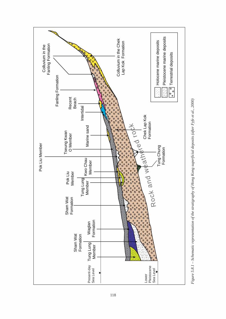
Roc
k an
d w
eath
ered
rock
Col
luvi
um in
the
Fanl
ing
Form
atio
n
Fanl
ing
Form
atio
n
Rec
ent
Bea
ch
Inte
rtida
l M
arin
e sa
nd
Tseu
ng K
wan
O M
embe
r
Pok
Liu
Mem
ber
Kwo
Cha
uM
embe
r
Pok
Liu
Mem
ber
Tung
Lun
gM
embe
r
Sha
m W
atFo
rmat
ion
Wag
lan
Form
atio
n
Sha
m W
atFo
rmat
ion
Tung
Lun
gM
embe
r
Col
luvi
um in
the
Che
kLa
p K
ok F
orm
atio
n
Che
k La
p Ko
kFo
rmat
ion
Tung
Chu
ngFo
rmat
ion
Hol
ocen
e m
arin
e de
posi
ts
Ple
isto
cene
mar
ine
depo
sits
Terre
stria
l dep
osits
Figu
re 5
.8.1
– S
chem
atic
repr
esen
tatio
n of
the
stra
tigra
phy
of H
ong
Kon
g su
perf
icia
l dep
osits
(afte
r Fyf
e et
al.,
200
0)
Pre
sent
-day
Sea
Lev
el
Low
erP
leis
toce
neS
ea L
evel
118
Colluvium is commonly a heterogeneous material consisting of rock fragments (ranging in size from several millimetres to a metre or so) supported within a sandy, clayey, silty matrix. Some generalisations are possible : • the larger boulders found in colluvium are generally
derived from coarse grained bedrock because of its widely-spaced joints,
• granitic colluvium is generally thicker than volcanic colluvium,
• older colluvium tends to have been eroded from drainage lines and is therefore now more likely to be found on interfl uves, and
• older colluvium tends to be stiffer or denser and displays more weathering of the clasts.
On Hong Kong Island, the Mid-Levels Study (GEO, 1982) identified three classes of colluvium based on morphology and soil characteristics. It was found that in general, soil density and strength increased with age, as did the degree of weathering of the boulders. The three classes of colluvium may represent separate climatic periods of deposition. Lai & Taylor (1984) also differentiated colluvium of different ages and extended the classification to include the source materials (i.e. bedrock lithology).
Based on the foregoing studies it is considered likely that colluvium throughout Hong Kong was formed during multiple events spanning from the mid-Pleistocene to the present, albeit perhaps, with increased intensity of mass wasting during wetter interglacial periods. Lai & Taylor (1984) report and illustrate a rare confirmation of a Holocene age for a colluvial deposit that was found overlying soft Holocene marine deposits. Sewell & Campbell (2005) report on a trial programme of age dating of relict landslide scars, which indicates ages of up to 50,000 years. There was also some evidence to suggest that some landscape surfaces were up to about 300,000 years in age.
Absolute age is important for certain purposes, such as calculating risk from natural terrain landslides (see Section 6.2). Relative age is also useful, e.g. subdividing colluvial deposits into units related to their relative age as inferred from detailed API or the degree of weathering of the clasts.
Depending on the degree of saturation, iron cementation of the matrix can significantly add to the material strength (Ruxton, 1986). Occasionally,
kaolin veins and to a lesser extent, kaolin-rich zones occur within Pleistocene colluvial deposits. They typically do so within the matrix, especially towards the base of these deposits, and around some clasts (Ruxton, 1986). It is considered that these occurrences are weathering related (Campbell & Parry, 2002).
The engineering properties of colluvium are likely to be influenced by the proportion and strength of cobbles and boulders, particularly if that proportion exceeds about 30% by volume (Irfan & Tang, 1993). However, the cobbles and boulders range in size and display varying states of weathering. This makes it difficult to estimate their contribution to overall mass strength. The variable composition of the matrix is reflected in the relatively wide range of the strength parameters given in Geoguide 1 (GEO, 1993). It is difficult to ascertain mass properties from small drillhole samples and colluvium is best examined in trial pits or exposures.
Relatively recent colluvium can contain moderately-to slightly-decomposed boulders which may be several metres across. Where these are encountered in drillholes, difficulties may arise in the interpretation of rockhead level (e.g. where the drillhole terminates within the boulder) or bedrock lithology (e.g. where the lithology of the boulder and the underlying bedrock are different and where the boulder and bedrock are separated by only a thin layer of saprolite). In such cases, engineering geological knowledge of the site setting and critical interpretation of other available data can facilitate the development of a representative geological model.
The hillside setting of colluvial deposits corresponds to high surface runoff and potentially to major groundwater throughflow at depth. Depending on the relative proportion of the two, surface and sub-surface erosion can occur. The permeability contrast around unweathered boulders promotes the development of soil pipes (see Section 4.4.6). Preferential drainage paths can also develop along the base of colluvium, and streams on areas of shallow bedrock commonly disappear on entering areas of colluvium. As a result, the build-up of transient perched water pressure in colluvium during intense rainfall is common (GCO, 1982).
Talus Talus comprises angular rock fragments derived from steep outcrops and cliffs. Although deposits visible
119

on hillsides are probably of relatively recent age, it is possible that older deposits exist at depth within the blanket of colluvial deposits. The size of individual fragments, and therefore potentially the size of voids, varies considerably and is mainly dependent on the joint spacing of the parent bedrock. The voids within these deposits are commonly unfilled.
The extent of talus in Hong Kong is much less than that of colluvium, but where present, talus can have significant engineering consequences. Large blocks of rock can make the design and construction of foundations difficult, and buried talus can provide preferential groundwater flow paths. Problems associated with buried talus are analogous to the problems encountered with bouldery colluvium beneath a fill slope at Tai Po Road, as described in Section 5.9.
Alluvium Colluvium interdigitates with and grades into alluvium where hillslopes intersect valleys. Interstratification of these deposits may be evident in vertical section or drillholes, though they are unlikely to persist laterally.
Where fluvial conditions exist, these are associated with finer grained alluvial floodplain deposits and networks of more granular channel sediments, with successive layers built up as streams meandered and coalesced. Alluvial deposits are commonly partly sorted, channelised and cross-bedded with successive cross cutting. Where the alluvial deposits are extensive, such as the Chek Lap Kok Formation, this high degree of small-scale sedimentary variability, when considered over a large area, can be sufficiently regular that a single set of soil parameters can be adopted for design of larger-scale engineering works. That is, despite the small-scale complexity of the geological model, the engineering behaviour of the ground can be greatly simplifi ed in the ground and design models (see Section 6.8).
Issues of engineering concern include the extent and rate of consolidation settlement and the potential for differential settlement. The permeability of the alluvium in situ is critically important. It is usually the case that laboratory oedometer tests underestimate the rate of settlement, partly because they are unable to take account of the presence of fine laminae and beds of fine sand. Alluvial clay can also cause stability problems in embankments, seawalls, trenches and
deep excavations.
Beggs & Tonks (1985) concluded that the alluvial sediments in the northwest New Territories could be divided into two categories with signifi cantly different engineering properties. The younger Holocene deposits (part of the Fanling Formation) are generally soft and normally consolidated, whereas the older Pleistocene deposits are stiff and over-consolidated. Table 5.8.1 provides some indication of the type of variation between the engineering properties of older and younger alluvium. However, the engineering characteristics of the alluvial deposits are very site specific.
An important feature of the alluvium now offshore is its upper surface, which was subaerially exposed immediately prior to the Holocene marine transgression. Two attributes of this surface are relevant to the design and construction of engineering works. Firstly the surface is channelled, resulting in an uneven base to the overlying soft Holocene marine mud. Secondly, the surface commonly has a subaerially weathered crust that facilitates the placement of fill material for reclamations, etc., without the risk of penetration into the underlying weaker material (Endicott, 1992). Section 6.8 provides details of the investigation and construction of the airport reclamation at Chek Lap Kok Island, including an account of the distribution and nature of this weathered crust, overconsolidation ratio of the alluvium, etc. Lo & Premchitt (1998, 1999) give a detailed account of the consolidation properties of the Chek Lap Kok Formation. Included within the alluvium now located offshore are sediments that were laid down in salt water or brackish water (Yim, 1992).
Section 6.10 discusses the large deposits of sands in old alluvial channels that have been dredged for use as fi ll material.
Lacustrine Deposits Localised lacustrine deposits occur in some areas of the fl at-lying terrain in the northern New Territories. These were formed by ponding of late Pleistocene rivers and streams, resulting in the accumulation of fine-grained sediments. The yellow-brown sediments commonly contain layers of grey silty clay rich in organic matter. These sediments tend to be soft, plastic, normally consolidated and relatively compressible.
120

PI (%) LL (%) %Clay %Silt
%Sand c’ (kPa) Φ(°)
Su (kPa)
20 - 55 40 - 80 20 - 50 40 - 70 0 - 50
5 28 30
cv (m2/year) Range
Average
1.0 -10.0
6.0
0.05 - 0.15
0.09
0.9 - 4.1
1.8 0.002
20 - 35 38 - 60 20 - 45 30 - 50 10 - 50
0 24 30
1.0 - 20.0
10.0
0.08 - 0.24
0.14
1.6 - 6.0
3.5 0.008
15 - 33 32 - 60 5 - 20
30 - 70 15 - 55
5 30 -
8.0 - 40.0
20.0
0.05 - 0.28
0.10
0.9 - 7.5
2.5 0.014
10 - 22 22 - 38 0 - 20
10 - 30 50 - 95
0 36 -
-
-
-
-
-
--
Range Average
Range Average
Cc (1+e0)
mv(x10-4) m2/kN
Engineering Properties
“Old Alluvial” Clay
“New Alluvial” Clay
Alluvial Silts
Alluvial Sand
C
Table 5.8.1 – Summary of alluvial material properties in Yuen Long area (after Beggs & Tonks, 1985)
Depression Infill The Tung Chung Formation (see Figure 5.8.1) comprises bouldery silts and sands that are only present in deep localised bedrock depressions, probably karst-related, in the Tung Chung-Brothers Islands area north of Lantau (see also the discussion and example in Section 6.5).
In many respects, these deposits are similar to the colluvium found elsewhere in Hong Kong. The type section at Tung Chung, for instance, consists of completely decomposed, rounded to sub-rounded boulders supported in a matrix of poorly sorted brown sandy silt (Fyfe et al., 2000). These materials were originally mistaken for colluvial deposits. However, detailed ground investigations and logging have indicated a depositional environment of deep, steep-sided doline depressions where the characteristics and distribution of the infilling sediment differ from that normally found in colluvial deposits. Delineation of these deposits has required extensive and specialised methods of ground investigation (Wightman et al., 2001) and specialised engineering geological input (Kirk, 2000).
5.8.4 Pleistocene Marine Deposits The Pleistocene rises in global sea-level associated with Quaternary interglacial periods only affected the lowest lying areas within the main drainage basins. Two events of sea-level rise, around 120,000 BP and
80,000 BP were responsible for the deposition of the Sham Wat and Waglan Formations respectively (Fyfe et al., 2000). These predominantly silt and clay marine sediments are confined to localised channels in the eroded surface of the Chek Lap Kok Formation. The importance of these deposits is that they are deeper and firmer than Holocene marine clay and the organic content of the intertidal sediments, particularly the Sham Wat Formation, can give rise to gas blanking of seismic records (see Section 6.8).
5.8.5 Holocene Marine Deposits
Overview The various deposits laid down as a result of the Holocene marine transgression are shown schematically in Figure 5.8.1. As the sea-level rose, it first flooded the drainage lines, which became inter-tidal creeks with deposition of basal sandy sediment, followed by organic-rich laminated silts (the Tung Lung and Pok Liu Members respectively, possibly late-Pleistocene in age). About 10,000 BP the rising sea flooded over the entire late Pleistocene alluvial plain. Tidal currents winnowed the surface of the old alluvium leaving transgressive granular deposits (the Kwo Chau Member). The sea continued to rise, and as seabed currents diminished, soft grey mud was deposited which blankets most of the present offshore area, commonly to a depth of about ten metres (the Tseung Kwan O Member).
121

Material Properties PI (%) LL (%) %Clay %Silt
%Sand c’ (kPa) Φ(°)
Su (kPa)
Marine clay 20 - 40 35 - 65 20 - 50 45 - 75 5 - 35
6 20
5 - 30
Marine silt 10 - 25 25 - 40 5 - 20
30 - 60 20 - 50
0 28
5 - 30 cv (m2/year)
Range Average
0.6 - 0.4 1.3
3.0 - 13.0 4.5
0.11 - 0.25 0.20
2.0 - 12.0 5.5
0.11 - 0.26 0.23
2.0 - 8.0 5.6
0.008 0.004
Range Average
Range Average
Cc (1+e0)
mv (x10-4) m2/kN
C Table 5.8.2 – Comparison of engineering properties of clayey and silty Holocene marine deposits in the Yuen Long basin area (after Beggs & Tonks, 1985)
As the sea rose further, it reached the late Pleistocene break of slope where the alluvial plain gave way to the colluvial slopes. From this point on the rising sea began eroding into the steeper hillslopes, washing fines offshore and leaving coarser granular material as beach deposits. By about 6,000 BP the sea stopped rising, then dropped again by about two metres to leave today’s shoreline. Intertidal deposits were laid down in the small estuaries around water courses. In the flat-lying terrain of the northwest New Territories the slight drop in sea-level left areas of the soft marine deposits inshore where they are now covered by a thin layer of recent alluvial sediment. Offshore, strong tidal flows in constricted areas locally resulted in sand deposits, including comminuted shell sands (see Figure 5.8.1).
Soft Marine Deposits The soft marine mud of the Tseung Kwan O Member has fairly similar geotechnical properties throughout Hong Kong and previous documented work can be useful in providing indicative design parameters (e.g. Yeung & So, 2001). However, there are variations in particle size distribution, especially closer to the shoreline, and these can affect material properties. Table 5.8.2 shows the range in parameters between clayey and silty marine mud from the Yuen Long basin. At a more detailed level, studies of the chemistry and microfabric, such as those of Tovey (1986), provide an insight into the causes of variations in geotechnical properties.
The main engineering concern with the soft marine mud is its compressibility and resulting settlement under imposed loads. Both the rate and the amount of settlement are important. Standard methods of field and laboratory testing can provide reliable predictions of settlement; however, two additional engineering geological factors need to be considered: • The rate of settlement can be signifi cantly affected
by thin laminae of coarse silt or fine sand, which are common, and which can act as drainage paths for release of excess porewater pressure (see Section 6.8).
• The total amount of settlement depends on the thickness of the mud, which is greater in areas of irregular pre-Holocene drainage channels. Offshore, delineation of the pre-Holocene drainage channels using seismic surveys can be problematic because of acoustic blanking due to gas bubbles in the sediments (Figure 5.8.2). This is especially associated with the Pok Liu Member (see the discussion in Section 6.8).
Recent anthropogenic mud containing sewage also gives rise to gas blanking within sheltered areas of the harbour where the lack of seabed currents or tidal flows allow the mud to accumulate.
In the last century, large areas of soft Holocene mud were excavated in the northwest New Territories to form ponds for rearing fish and ducks. The excavated soil was used to form bunds separating the
122

Acoustic blankingAcoustic blanking
50 m
10 m
Figure 5.8.2 – Seismic boomer profile showing acoustic blanking caused by gas associated with an intertidal channel (after Fyfe et al., 2000)
ponds. Portions of these pond areas are now being redeveloped for low-rise housing and infrastructure. The geotechnical characteristics of this ground need special investigation as the natural soil structure and properties have changed significantly and layers of extremely soft, organic-rich sediment have accumulated in ponds.
5.9 MADE GROUND
5.9.1 Introduction Although made ground exists in many different engineering contexts, almost all of it is encountered in two types of situation: • reclamations and fill platforms on low-lying,
coastal or near-shore terrain • development platforms and roads on sloping
terrain
In both situations, the performance of the made ground is very dependent on the nature of the fill and on the method of construction.Although made ground was not formed by natural processes and therefore does not possess the same patterns of material and mass characteristics found in natural ground, many engineering geological principles are relevant to the assessment of this material. Similarly, whilst the use of a geological model approach is more limited than in cases of natural ground, it is still applicable, notably in respect of engineering geological aspects of the natural topography and ground conditions prior to filling.
Although reclamation is by far the most common example of made ground (more than 60 km2
of the land in Hong Kong is reclamation), the unpredictability of made ground on hilly terrain is much more of a concern because of the potential consequences of failures. Coastal reclamation is generally in relatively stable environments, although some failures have occurred (Blower et al., 1993) and extensive reclamation may affect the regional groundwater regime (Jiao, 2000b). In contrast, fill slopes on hillsides are typically in meta-stable environments, and the water table and groundwater flow can vary rapidly and dramatically, which may give rise to potential instability if groundwater control measures are inadequate.
After the catastrophic fill slope failures at Sau Mau Ping in 1972 and 1976 (see Section 5.9.4), design and construction of fill slopes began to improve significantly. Discussion in this section is essentially directed at the older areas of made ground on sloping terrain where stability and other problems are more of a concern. Similarly, it is the made ground of older reclamations and inland site formations on low-lying terrain that are dealt with in this section.
Issues associated with reclamations are addressed separately in Section 6.8, while Section 6.3 covers some issues related to site formations. The problems associated with made ground that has become contaminated by industrial and other activities are covered in Section 6.9.
123

5.9.2 Historical Reclamations and Fill Platforms on Low-lying Terrain
General Reclamation has been carried out widely in Hong Kong. The oldest reclamations are located along the original coastline of north Hong Kong Island and around Kowloon, with later reclamations located progressively further from the central harbour. The general areas of reclamation are well known (e.g. Fyfe et al., 2000).
Nature of the Made Ground Where older reclamations were extended, the later works may incorporate earlier structures such as concrete or masonry sea walls. Domestic and industrial waste may also occur in some of the older reclamations, and the engineering behaviour of this waste material is likely not only to be highly variable, but also to change over time. However, the presumption that the greater the age of a reclamation the greater the variability of the fill material might not always be justified. One reason being that when the earliest reclamations were formed, natural material from borrow areas was more readily available than construction and demolition material now commonly used.
Construction Techniques The lower layers of reclamations are placed below water and if the fill is variably graded there is the potential for segregation of material. While the portion of made ground above the water table may be compacted, or simply becomes compacted through usage, below the water table this is unlikely. Many earlier reclamations were formed on top of reasonably competent nearshore material, e.g. beaches. However, later reclamations, further from the original shoreline, were formed on the soft Holocene marine deposits. The process of end tipping of fill into deep water in the past resulted in many instances of displacement of soft marine mud forming ‘mud waves’ (Endicott, 2001). Subsequent excavations into such reclamations have occasionally shown that the lower layers of fill material have sunk into and displaced the mud, thus posing additional difficulties with certain types of basement works and tunnels.
Potential Problems The grading of filling material is an important
characteristic of made ground because the presence of voids can provide the opportunity for long-term downward migration of finer material, with the resulting upward migration of voids, possibly even reaching the ground surface. This can be particularly important where layers of unblinded and irregularly sized rockfill have been incorporated into the formation of made ground.
The nature of the made ground in reclamations can cause problems during new construction works, e.g. the presence of large boulders, dumped tyres and pieces of reinforced concrete, could pose difficulties during piling operations. Furthermore, gases derived from decomposed organic materials within the fill, can be problematic in tunnels and excavations.
Excavations for basements and tunnels require dewatering, and special precautions are needed to minimise settlement in adjacent areas. Settlement occurs by a combination of self-weight compaction and washing out of fines by groundwater flowing towards the excavation. Consequently, ground investigation outside the site to characterise the made ground and to assess the potential for settlement may be required.
5.9.3 Development Platforms and Roads on Sloping Terrain
General An understanding of geomorphological processes, associated regolith types and hydrogeology is important when constructing or investigating made ground on hillslopes. Reference should be made to Section 4.5, which discusses these processes.
Nature of the Made Ground and Associated Hydrogeology Large areas of sloping terrain in Hong Kong have been modified by cut and fill activities. The material properties of the fill can be inferred to some extent, from the geology in the cut area. For sites where the excavated material was used as fill it may be problematic to differentiate the fi ll from in situ material. Therefore, investigation using trial pits that give relatively large areas of exposure should be considered. In contrast, development platforms that have been formed with imported fill can contain geological material quite different from that elsewhere on the site.
124

The full three dimensional extent of hillside fill platforms may be difficult to determine if the made ground pre-dates the earliest aerial photographs. Nevertheless, aerial photograph interpretation can usually provide a measure of the plan area of such features, while the geomorphology of the surrounding terrain can provide some indication of the pre-filling topography (Shaw & Owen, 2000).
Bodies of fill material on sloping ground are prone to internal erosion over time as a result of subsurface groundwater flow, and in this respect the location of pre-existing drainage lines in relation to the made ground is very important. Unless careful drainage measures were constructed prior to placing fill in a natural drainage line, progressive sub-surface erosion can be expected to remove finer material from lower layers of the fill. Later, downward migration of fines into the voids can result both in settlement and more importantly, blockage of the drainage path with consequent problems of high pore pressures developing in the fill. Therefore, deposits of fi ll on hillslopes require careful investigation of the subsurface groundwater regime and any associated erosion (see Section 5.9.4).
Construction Techniques The engineering characteristics and performance of the fill will vary depending on its suitability and the compaction techniques used during emplacement. Historically, although sourcing suitable fill was occasionally difficult, inadequate compaction is the main cause of failures of hillside fi ll slopes. Most of the older hillslope platforms were formed by end-tipping of material onto the slope so as to progressively build up the desired platform. Basal drainage blankets were not routinely installed. End-tipping tended to result in layering parallel to the slope and, if there are differences in material grading between layers, preferential drainage paths can develop parallel to the slope. The most serious disadvantage of the end-tipping is that the only compaction achieved is by self-weight. Therefore, a prime objective of ground investigations of old fill slopes is to determine the nature of the material and the degree of relative compaction.
Potential Problems Stability problems result from the combination of uncompacted fill and lack of adequate drainage. Infiltration of surface and groundwater can cause
sliding, localised washouts and static liquefaction of the material (Wong et al., 1997). Figure 5.9.1 illustrates possible triggers and contributory factors in fill slope failures. Fill slope failures can result in the sudden development of large volumes of very mobile debris and the consequence of such failures can be disastrous, as occurred at Sau Mau Ping as described below.
5.9.4 Case Studies
Sau Mau Ping Fill Slope Failure in 1976 On 25 August 1976, a fill slope immediately behind Block 9 of the Sau Mau Ping Estate failed and the resulting debris buried the ground floor of the block, killing eighteen people (Figure 5.9.2). After the disaster, a detailed investigation had the following findings: • The fill, composed of completely decomposed
granite, was in an extremely loose state to a depth of at least 2 m below the slope surface, the dry unit weight being in the range of 12.5 to 15.5 kN/m³ (average 13.5 kN/m³), corresponding to about 75% of standard compaction.
• The fill was layered parallel to the slope surface, with layers between about 100 and 300 mm thick.
• Beyond the crest of the slope, the dry unit weight of the materials was low but variable to a depth of 7 m, dropping from about 16.5 kN/m³ to about 12 kN/m³ (90% to 70% of standard compaction), showing a gradient of densities with depth consistent with the soil having been placed in layers of 1 m to 3 m thick. At greater depths the dry unit weight was about 15 kN/m³.
These findings indicated that the fill had been end-tipped with no compaction. Such conditions can result in the following: • The soil strength being very much less than
would be obtained with well-compacted fill. • Rainwater infiltration wetting the soil to an
appreciable depth and reducing the strength even further.
• The loose soil structure is vulnerable to collapse during shearing, thereby resulting in significant increase in pore water pressure and reduction of shear strength when failure occurs under a high degree of saturation.
The investigation considered various possible
125

Figure 5.9.1 – Triggers and contributory factors for fill slope failure (Sun, 1998)
sources of water ingress, including direct surface Loss of Grout Associated with Voids in a Fill infiltration, rising groundwater from below and Slope Below Tai Po Road infiltration from drainage pipes. The overall The fill slope located below Tai Po Road was conclusion was that direct surface infiltration, constructed some time between 1949 and 1963. The possibly aggravated by slight leakage from surface slope was upgraded in the early 1980s, including re-drainage, was the prime cause of the high degree of compacting the top 3 m of the slope and reducing the saturation of the fill. Full details of the investigation gradient of the slope by constructing a retaining wall are given in B&P (1976), Hong Kong Government at the toe (Figure 5.9.3). In 2004 upgrading works (1977) and Knill et al. (1999), the latter being a were carried out under the Landslip Preventive reprint of the original 1977 report. Measures (LPM) Programme. These works included
Figure 5.9.2 – View of the fill slope failure at Sau Mau Ping Estate in 1976
126
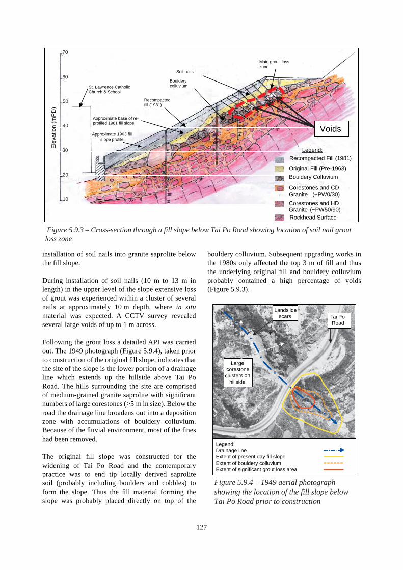
Original Fill (Pre-1963)
Bouldery colluvium
Approximate base of re-profiled 1981 fill slope
Approximate 1963 fill slope profile
Legend:
Voids
St. Lawrence Catholic Church & School
Main grout loss zone
Recompacted fill (1981)
Soil nails
Recompacted Fill (1981)
Bouldery Colluvium
Corestones and CD Granite (~PW0/30) Corestones and HD Granite (~PW50/90) Rockhead Surface
Figure 5.9.3 – Cross-section through a fill slope below Tai Po Road showing location of soil nail grout loss zone
70
60
50
40
30
20
10
Ele
vatio
n (m
PD)
installation of soil nails into granite saprolite below the fi ll slope.
During installation of soil nails (10 m to 13 m in length) in the upper level of the slope extensive loss of grout was experienced within a cluster of several nails at approximately 10 m depth, where in situ material was expected. A CCTV survey revealed several large voids of up to 1 m across.
Following the grout loss a detailed API was carried out. The 1949 photograph (Figure 5.9.4), taken prior to construction of the original fill slope, indicates that the site of the slope is the lower portion of a drainage line which extends up the hillside above Tai Po Road. The hills surrounding the site are comprised of medium-grained granite saprolite with significant numbers of large corestones (>5 m in size). Below the road the drainage line broadens out into a deposition zone with accumulations of bouldery colluvium. Because of the fluvial environment, most of the fines had been removed.
The original fill slope was constructed for the widening of Tai Po Road and the contemporary practice was to end tip locally derived saprolite soil (probably including boulders and cobbles) to form the slope. Thus the fill material forming the slope was probably placed directly on top of the
bouldery colluvium. Subsequent upgrading works in the 1980s only affected the top 3 m of fill and thus the underlying original fill and bouldery colluvium probably contained a high percentage of voids (Figure 5.9.3).
Legend: Drainage line Extent of present day fill slope Extent of bouldery colluvium Extent of significant grout loss area
Figure 5.9.4 – 1949 aerial photograph showing the location of the fill slope below Tai Po Road prior to construction
Landslide scars
Large corestone clusters on
hillside
Tai Po Road
127

Many old fill slopes were constructed across drainage lines to form roads or building platforms, and ground conditions similar to that described above probably occur elsewhere in Hong Kong. A geological model which incorporates a detailed API, rather than just a simple account of the site history, can assist in the identification of sites that may have similar potential problems. Consideration of the geomorphology of the area, including the catchment above the site and the groundwater system prior to deposition of fi ll, may assist in assessing how the groundwater system might have changed after the infilling took place, including any development that might have modified the surface water drainage regime. If a potential problem is identified, investigation methods to confi rm the presence of voids may include resistivity surveys of the slope to locate potential areas of voids (see Section 6.4.7) and confirmatory drillholes through the slope where voids are suspected.
Where such ground conditions are not foreseen, they can have significant implications on cost and programme. This highlights the need for engineering geological input at an early stage. Consideration should also be given to the hydrogeology of the site when assessing the most appropriate remedial measures. Relatively loose soil material with significant boulder content is susceptible to internal erosion via groundwater seepage and fl ow. Excessive erosion could result in subsidence (see Section 6.4.7). On the other hand, any measures that block or hinder groundwater flow could also potentially have adverse effects on the stability of the slope.
128