engineering, inc. - summitracingstatic.summitracing.com/global/images/instructions/4gd218im.pdf ·...
TRANSCRIPT

GM VORTEC 4.3L V-6S-10/Sonoma/Jimmy/Blazer
Supercharger SystemInstallation Instructions
1996-1998 MODEL YEARS
50 STATE SMOG LEGAL PER CARB EO #D-213-16
®
ENGINEERING, INC.1650 PACIFIC AVENUE • CHANNEL ISLANDS, CA 93033-9901
P/N: 4GD020-010©1999 Vortech Engineering, Inc.All Rights Reserved. Intl. Copr. Secured26OCT99 V 1.1

This product is protected by state common law,copyright and/or patent. All legal rights therein arereserved. The design, layout, dimensions,geometry, and engineering features shown in thisproduct are the exclusive property of VortechEngineering, Inc. This product may not be copiedor duplicated in whole or part, abstractly orfundamentally, intentionally or fortuitously, norshall any design, dimension, or other informationbe incorporated into any product or apparatuswithout prior written consent of VortechEngineering, Inc.
NOTICE
1650 Pacific Avenue, Channel Islands, CA 93033 • PHONE (805) 247-0226FAX (805) 247-0669 • http://www.vortechsuperchargers.com • M-F 8AM - 4:30PM (PST)
®
ENGINEERING, INC.
© 1999 VORTECH ENGINEERING, INC.All Rights Reserved, Intl. Copr. Secured

Before beginning this installation, please read through this entire instruction booklet and the Street SuperchargerSystem Owner's Manual which includes the Limited Warranty, Warranty Registration form and return envelope.Vortech supercharger systems are performance improving devices. In most cases, increases in torque of 30 to 35%and horsepower of between 35 and 45% can be expected with the boost levels specified by Vortech Engineering. Thisproduct is intended for use on healthy, well maintained engines. Installation on a worn-out or damaged engine is notrecommended and may result in failure of the engine as well as the supercharger.Vortech Engineering is not responsible for engine damage.Installation on new vehicles will not harm or adversely affect the "break-in" period so long as factory break-inprocedures are followed.For best performance and continued durability, please take note of the following key points:1. Use only premium grade fuel 92 octane or higher (R+M/2).2. The engine must have stock compression ratio.3. If the engine has been modified in any way, check with Vortech prior to using this product.4. Always listen for any sign of detonation (pinging) and discontinue hard use (no boost) until problem is resolved.5. Perform an oil and filter change upon completion of this installation and prior to test driving your vehicle.
Thereafter, always use a high grade SF rated engine oil or a high quality synthetic, and change the oil and filter atleast every 3,000 miles or less. Never attempt to extend the oil change interval beyond 3,000 miles, regardlessof oil manufacturer's claims as potential damage to the supercharger may result.
6. Before beginning installation, replace all spark plugs that are older than 1 year or 10,000 miles with original heatrange plugs as specified by the manufacturer and reset timing to factory specifications (follow the proceduresindicated within the factory repair manual and/or as indicated on the factory underhood emissions tag). Do notuse platinum spark plugs unless they are original equipment. Change spark plugs every 20,000 miles and sparkplug wires every 50,000 miles or earlier.
TOOL & SUPPLY REQUIREMENTSFactory repair manual3/8" socket and drive set: SAE & metricDrill motor, 3/32" 5/8" and #16 drill bitsFlat #2 screwdriverOpen end wrenches: 5/16", 3/8", 7/16", 1/2", 9/16", 5/8"
10mm, 13mm, 15mm, 16mm, 17mm, 18mmHammerSilicone sealerOil filter wrenchOil filterSF rated quality engine oilGasket scraperPunch (tapered)3/8" NPT tapFuel line disconnect toolRota Broach (9/16) boring tool (Snap-on # GA219-A)
If your vehicle is in excess of 10,000 miles since its last spark plug change, thenyou will also need:
Spark plug socketNEW spark plugs
1996-1998GM VORTEC 4.3L V-6 S-10/Sonoma/Jimmy/Blazer
Installation Instructions50 State smog legal, as per CARB EO #D-213-16
Congratulations on selecting the best performing and best backed automotive supercharger available today...the VORTECH® V-1® supercharger!
4GM218-050S
© 1999 VORTECH ENGINEERING, INC.All Rights Reserved, Intl. Copr. Secured

®
ENGINEERING, INC.
1996-1998 GM VORTEC 4.3L V-6
PARTS LIST
IMPORTANT: Before beginning installation, verify that all parts are included in the kit. Report any shortages or damaged parts immediately.
Part Number Description Quantity
2A228-280 Supercharger Assembly 12A128-280 Supercharger 12A036-312 Supercharger Pulley 3.125" 6 groove 17K375-040 3/8 AN960 Flat Washer 12A040-011 Pulley Retainer 17B375-125 3/8"-24 x 1-1/4" HX CLS 17U100-070 Key, 3/16 x 3/16 x 7/8 1
4GD111-021 Mounting Bracket Assembly 17A375-101 3/8 x 1" Socket Head 17A375-124 3/8"-16 x 1-1/4” HH Cap Screws 27K375-040 3/8” AN960 Flat Washers 167A375-100 3/8"-16 x 1” HXHD Bolts 57A375-275 3/8"-16 x 2-3/4” HX Cap Screws 2
4GM011-021 Mounting Bracket 14GM010-033 Mounting Plate 17A375-075 3/8-16 x 3/4" HXHD Bolts 6
4GD011-032 Spring Tensioner 12A046-102 Belt 14FA016-170 Idler Pulley 14FD017-011 Spacer, Idler 17C012-050 12mm x 1.75 x 50mm Bolt 14FA016-171 Dust Cover 14GD116-150 Idler Pulley Assembly 14GD010-060 Coil Mount bracket 14GM010-050 Heat Shield 17A250-050 1/4-20 x 1/2" SH Cap Screw 17J250-001 1/4" SAE Washer 1
4GD014-010 Radiator Pipe 17R002-024 #24 Gold Seal Hose 27C008-100 #8-32 x 1" Socket Head Cap Screw 47F008-032 8-32 Hex Lock Nut 47J008-001 #8 Flat Washer 4
4GD112-010 Air Intake Assembly 14GD112-012 Air Inlet Tube 14GD015-022 Air Inlet Support 18H040-085 Air Filter 17S350-200 3-1/2 x 2 Sleeve 17R002-056 #56 Gold Seal Hose Clamp 27U035-001 3-1/2 Flex Hose x 12" 17R002-052 #52 Gold Seal Hose Clamp 37U038-000 3/4" Heater Hose 17U100-056 90° Vent Tube 17P500-026 1/2 NPT 3/4 90° Barb 17R001-008 #8 Hose Clamp 17U034-016 1" GS Hose x 4" 1
4GD112-030 Air Box Duct Assembly 17U100-057 Grommet 17S300-101 3 x 1 Sleeve 17R002-016 #16 Gold Seal Hose Clamp 2
4GD130-036 Oil Drain Assembly 17R001-008 #8 Stainless Hose Clamps 27P375-017 3/8" NPT x 1/2” Straight Hose Barb 17U030-036 1/2” Oil Drain Hose x 24” 17U100-055 Tie Wraps 2
4GD130-026 Oil Feed Line Assembly 17U030-026 1/4” Oil Feed Hose x 48” 17P525-067 .525” Crimp Ferrules 27P250-066 #4 Swivel x 1/4” Hose Barb Fittings 27P125-103 -4 x 45° 1/8" NPT Male Elbow 17P375-033 3/8 NPT x 3/8 NPT SRT EL 17P375-018 3/8-1/8 NPT Bushing 2WD/4WD 17P125-026 90° 1/8 NPT x #4 Fitting 1
4GD238-068 FMU With Lines 16Z110-134 Fuel Management Unit 17U030-046 5/32" Vacuum Line x 4.3" 1
4GD145-010 Female FMU Line (to tank) 14GD145-020 Male FMU Line (to rail) 1
Part No. 4GD218-050/058S
Part Number Description Quantity
4GD112-020 Air Discharge Assembly 17R002-044 #44 Hose Clamps 48D001-001 Bypass Valve 17R002-016 #16 Hose Clamps 47P156-082 5/32” Tee 17U030-046 5/32” x 24” Vacuum line 1
4GD012-020 Discharge tube 14GD050-011 Discharge Plenum 17W100-070 O-Ring, Throttle Body 17S275-200 2-3/4 x 2 Sleeve 27P500-156 1/2" Vac. Tee x 1/4 NPT 17P250-033 1/4 x 5/32 Red Union 17P250-039 1/4 NPT Fem. x 1/4 Hose 17U030-030 1/4" Vacuum Hose (.0833") 17U034-016 1" GS Hose (3/16") 17U034-016 1" GS Hose (1/4") 12A017-028 Plenum, Spacer A 12A017-029 Plenum, Spacer B 12A017-030 Plenum Spacer C 27C060-600 M6 x 6" TB 4.3 Stud, front 27C060-387 M6 x 3.87" 4.3 Stud, RR 17F006-093 6mm Nylock Nut 37J006-093 6mm Washer 3
4GD101-002 Fuel Pump Assembly 15W001-014 Fuse Holder 15W001-015 20 amp Blade Type Fuse 15W001-017 Large Ring Terminal 15W001-019 12-10 Ga. Solderless Connector 17J010-001 #10 Flat Washers 47U100-055 6" Nylon Tie Wraps 48F101-200 T-Rex Wiring Assembly 17F008-020 M8 x 1.25 Nut 17U031-018 5/16" Fuel Hose x 1.5" 18F001-200 200 Inline Fuel Pump 17P375-006 3/8 to 5/16 Fuel Fitting 17U032-016 3/8" Fuel Hose x 4.75' 17R004-003 14.5 Stepless Clamp 25W001-022 T-Tap Connector 15W001-042 12-10GA 3/16" Ring Terminal 47E010-049 #10 x 3/4 Hex Head Sheet 57R004-002 17.0 Stepless Clamp 17R001-004 #4 Hose Clamp 1
5A101-010 HI-6TR Assembly 15A001-009 HI-6TR Ignition System Assy. 15W001-001 Wire Tap 15W001-009 16-14GA Male Slide 105W001-010 16-14GA Female Slide 105W001-011 16-14GA Eyelet .25: hole 25W001-014 Fuse Holder 10GA Wire 15W001-015 Fuse, Blade Type 20 amp 15W001-017 Large Ring Terminal 12GA 25W001-020 3/4" Plastic Wire Loom 15W012-000 12GA, STRD Wire, Red 1
\ 5W012-010 12GA Wire, Black 15W022-120 22GA, STRD Wire, Brown 17E010-046 #8 x 3/4 Sheet Metal 17P156-082 5/32 Tee 17U030-046 5/32" Vacuum Line 17U100-055 Tie Wrap, 6" Nylon 107U375-001 Velcro-Hook 1" Black 17U375-002 Velcro-Latch 1" Black 15W018-010 18GA, STRD Wire, Red 15W018-020 18GA, STRD Wire, Black 15W018-060 18GA, STRD Wire, Orange 15W018-240 18GA, STRD Wire, White/Yellow 1
70000 Inspector Number 15W001-040 12-10GA Female Slide 25W001-041 12-10GA Male Slide 2
© 1999 VORTECH ENGINEERING, INC.All Rights Reserved, Intl. Copr. Secured

2. OIL DRAIN
A. To provide an oil drain for the supercharger, it isnecessary to make a hole in the oil pan. Locateand mark hole as per graphic and photo. It isbest to punch the hole rather than drill.
B. Remove the factory anti-roll bar brackets (2) fromthe frame and allow the bar to temporarily dropdown. Unplug the factory crank trigger connectorfrom the sensor located in the timing cover.
C. Carefully drill a pilot hole (the same diameter asthe Rota Broach pilot) into the marked spot onthe oil pan (this procedure may also be done byremoving the oil pan if you are unsure of yourability to perform the following steps properly).Drill slowly as to catch most of the aluminumchips from the hole being drilled. Using the 9/16" Roto Broach, very slowly machine a hole inthe pan (use the previously drilled hole as aguide). Stop machining just before the toolbreaks through into the oil pan. Using a scribeor a small screwdriver, remove the remainingdisc-shaped oil pan piece (this allows you toremove the pan slug before it falls into the oilpan and keeps most of the aluminum chips out).
1. COMPONENT REMOVAL
A. Disconnect the negative battery cable from the battery.B. Remove and set aside the following components:
-The entire air inlet/filter box assembly, including thethrottle body resonator and all hardware including the throttlebody mounting bolts.
-The crankcase vent tube from the right side (passenger) valvecover.
-The accessory drive belt.-The tensioner and idler from the alternator mounting bracket.-The alternator and bracket.-The 3/8" stud protruding from the right side cylinder head.
C. Drain the contents from the radiator into a clean container.D. Remove lower radiator hose.
1
NOTE: Removal of the oil pan may ease oildrain fitting installation on someapplications.
NOTE: The factory transmission cooler linesmay require bending to clear thesupercharger oil drain hose.
PUNCH HOLETHROUGH(DIRECTLYUNDERNEATHCORNER PANBOLT)
HOLE MUST BEMADE FROM THESIDE OFTHE PAN
OIL PAN BOLTS
FRONT VIEW
3/4”
BOTTOM VIEW
© 1999 VORTECH ENGINEERING, INC.All Rights Reserved, Intl. Copr. Secured

3. OIL FEED
A. The supercharger uses engine oil forlubrication and must have an oil feed lineconnected to a filtered oil access on theengine.
B. Remove the 3/8” NPT plug located on theengine block just above the oil filter boss.Replace the plug with the supplied 3/8"NPT elbow. Connect the remaining fittingsas shown (see graphic).
C. Connect the supplied feed line to the flarefitting and make a gentle downward looparound and back toward the front of theengine (see graphic). Secure the hosewith the tie wraps provided, routing it awayfrom exhaust heat, chaffing and/or sharpobjects. Temporarily cover the open endfrom debris until the connection is madeto the supercharger in step 5.
NOTE: Use clean engine oil on thepipe threads. Teflon tape and sealantis not recommended, as it mightloosen and cause blockage of thesmall oil feed orifice resulting insupercharger failure.
2
2. OIL DRAIN, cont'd.
D. Tap the hole with a 3/8" NPT tap approximately 1/4" deep. Pack theflutes of the tap with heavy grease to hold chips.
E. Thoroughly clean the threaded area. Apply a small amount of siliconesealer to the new threads. Apply more sealer to the supplied 3/8"NPT x 1/2" barb fitting. Install the fitting into the pan. Make sure aseal is formed around the entire fitting.
F. Drain the engine oil, install a new filter and refill with fresh oil.G. Reattach anti-roll bar and crank trigger connector.
OILFILTER
TO SUPERCHARGER
4WD MODELS: Connect the feed hoseand fittings to the remote oil filter bossat the front of the vehicle. (See photo)
© 1999 VORTECH ENGINEERING, INC.All Rights Reserved, Intl. Copr. Secured
3/8 NPTSTREET ELBOW
ROUTE HOSE AROUNDTO FRONT OF VEHICLE(ROUTE ALONG OILCOOLER LINES)
3/8 - 1/8 NPTBUSHING
1/8” NPT45° FLARE
ENGINE BLOCK
REAR VIEW - 2WD ONLY
4 WD ONLY
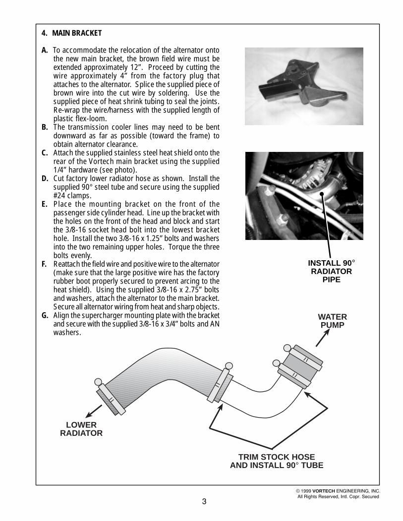
4. MAIN BRACKET
A. To accommodate the relocation of the alternator ontothe new main bracket, the brown field wire must beextended approximately 12”. Proceed by cutting thewire approximately 4” from the factory plug thatattaches to the alternator. Splice the supplied piece ofbrown wire into the cut wire by soldering. Use thesupplied piece of heat shrink tubing to seal the joints.Re-wrap the wire/harness with the supplied length ofplastic flex-loom.
B. The transmission cooler lines may need to be bentdownward as far as possible (toward the frame) toobtain alternator clearance.
C. Attach the supplied stainless steel heat shield onto therear of the Vortech main bracket using the supplied1/4” hardware (see photo).
D. Cut factory lower radiator hose as shown. Install thesupplied 90° steel tube and secure using the supplied#24 clamps.
E. Place the mounting bracket on the front of thepassenger side cylinder head. Line up the bracket withthe holes on the front of the head and block and startthe 3/8-16 socket head bolt into the lowest brackethole. Install the two 3/8-16 x 1.25” bolts and washersinto the two remaining upper holes. Torque the threebolts evenly.
F. Reattach the field wire and positive wire to the alternator(make sure that the large positive wire has the factoryrubber boot properly secured to prevent arcing to theheat shield). Using the supplied 3/8-16 x 2.75” boltsand washers, attach the alternator to the main bracket.Secure all alternator wiring from heat and sharp objects.
G. Align the supercharger mounting plate with the bracketand secure with the supplied 3/8-16 x 3/4” bolts and ANwashers.
3
© 1999 VORTECH ENGINEERING, INC.All Rights Reserved, Intl. Copr. Secured
INSTALL 90°RADIATOR
PIPE
WATERPUMP
TRIM STOCK HOSEAND INSTALL 90° TUBE
LOWERRADIATOR

5. SUPERCHARGER INSTALLATION
A. Attach the 1/2” oil drain hose to thesupercharger and secure with the #8 hoseclamp.
B. Route the hose down the rear of the mainbracket while lowering the supercharger intothe proper mounting location on the plate.Be sure that the oil drain hose remainsunkinked with smooth bends.
C. Using the five supplied 3/8-16 x 1” bolts andAN washers, secure the supercharger to themounting plate.
D. Route the oil drain hose around the maincasting and down to the fitting in the oil pan.Make sure that the hose runs below thepositive alternator lug, but still remainsrunning “downhill”. It is very important thatthe oil drain hose is free from restrictions,tight bends, kinks or any other drainobstructing conflict. Route the hose awayfrom direct exhaust heat. Trim hose length ifnecessary and secure to the oil pan with thesupplied #8 hose clamp.
E. Attach the 1/8 NPT x 45° brass fitting to thesupercharger oil feed. Use a 1/2” wrench tohold the feed fitting while tightening the 45°fitting. Attach the oil feed hose to thesupercharger.
F. Using the tie wraps provided, secure the feedand drain systems away from heat and/orsharp objects.
4
OIL DRAINHOSE
WARNING: The oil system contains asmall orifice that is easily plugged. Donot use any type of sealant on any of thethreads. Instead, use clean engine oil.Disassemble and blow out the entire lineif there is any question.
© 1999 VORTECH ENGINEERING, INC.All Rights Reserved, Intl. Copr. Secured
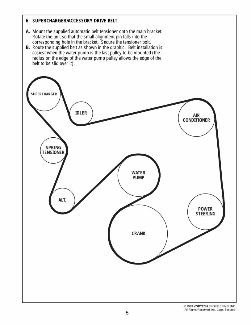
6. SUPERCHARGER/ACCESSORY DRIVE BELT
A. Mount the supplied automatic belt tensioner onto the main bracket.Rotate the unit so that the small alignment pin falls into thecorresponding hole in the bracket. Secure the tensioner bolt.
B. Route the supplied belt as shown in the graphic. Belt installation iseasiest when the water pump is the last pulley to be mounted (theradius on the edge of the water pump pulley allows the edge of thebelt to be slid over it).
5
SUPERCHARGER
IDLER
SPRINGTENSIONER
ALT.
WATERPUMP
CRANK
POWERSTEERING
AIRCONDITIONER
© 1999 VORTECH ENGINEERING, INC.All Rights Reserved, Intl. Copr. Secured

7 . COIL RELOCATION/IGNITION INSTALLATION
A. Remove ignition coil and bracket from thefactory location.
B. Separate the coil and module from factorymounting bracket.
C. Following the photo, install the coil andmodule to the supplied bracket using thesupplied hardware.
D. Mount the coil and bracket assembly to theintake manifold. Use the factory studs andnuts to secure the coil. Refer to photo.
E. Remove the interior center console (betweenthe two front seats). Mount the supplied igni-tion control box assembly into the vehicle in-terior in one of two possible locations (alter-nate mounting locations of the control box,retard knob and MAP sensor may vary suitingthe taste/preference of the installer).1. Pickup truck models (S-10/Sonoma):
a. The suggested mounting location is inthe center console between the twoseats (remove the center console andmount the control unit vertically in therear).
b. The retard knob can mount in the for-ward portion of the tray in the console.Mount the MAP sensor under the con-sole.
6
© 1999 VORTECH ENGINEERING, INC.All Rights Reserved, Intl. Copr. Secured
SUPPLIED COILBRACKET
COIL MOUNTINGLOCATION
HEAVY RED
HEAVY BLACKTO BATTERY +
TO GROUND
FACTORY GMHARNESS
(UNPLUGGEDFROM COIL)
IGNITION COIL
PINK
GREEN(OR WHITE)
PIN
K
GREEN(OR WHITE)
CUT HEREAND ATTACHCONNECTOR
X
X
WIRE TAP
RED
WHITE
BLACK
ORANGE
GREEN TACH (TAPE UP)
*GREY MAGNETIC TRIGGER HARNESS (TAPE UP)
YELLOW (TAPE UP)
BLACK (GROUND)BR
OW
N (
RE
TAR
D IN
PU
T)
RE
D
SUPPLIED MAP SENSOR
MANIFOLDVACUUM
3 WIRE HARNESS RANECELECTRONICS
HI-6TRTIMING RETARD CONTROL
RETARD
CRANEcams®
HI-6TR CAPACITIVE DISCHARGE IGNITIONWITH AUTO-SEQUENCE REV LIMITER
*NOTE: CABLE CONTAINS RED AND BLACKLEADS. MAKE SURE LEADS DO NOT CONTACTEACH OTHER AND SHORT UNIT WHEN TAPING UP.

7 . COIL RELOCATIONIGNITION INSTALLATION, CONT'D.
E. 2. SUV models (Blazer/Jimmy)a. The suggested mounting location is in the storage
box located next to the back seat on the passengerside of the vehicle.
b. The retard knob and MAP sensor can mount in thecenter console as the pickup trucks do. The brownretard wire and thin red power wire must be run overto the remote mounted ignition box.
F. Follow the wiring diagram and connect all components asshown. Connect a manifold sourced vacuum line usingthe supplied 5/32” hose and tee (use the FMU tap loca-tion). Route the extended coil wires and previously at-tached vacuum hose from the engine compartment backalong the frame rail and to the transmission crossmember.Drill a 5/8” hole through the floor of the vehicle from thebottom of the center console location for wire/vacuum hosepass through. Route the wire/vacuum hose bundle up intothe passenger compartment using the previously drilledhole.
G. Use the supplied cable ties to keep the wires secure andaway from moving/sharp/hot objects. Do not attempt tostart the vehicle without all component installed as shown.
H. Ignition Boost Control operation1. The Ignition/Boost Control unit is designed to retard
ignition in relation to boost.2. The unit is adjustable from 0° of ignition retard to 4° of
ignition retard for each pound of boost, up to a maxi-mum of 20°.
3. Using the 1° per pound position as a starting point,adjust the ignition retard knob until just beyond thepoint of detonation. Use third gear for testing in a safearea or road. Adjust the retard according to changes inaltitude and fuel quality.
7
© 1999 VORTECH ENGINEERING, INC.All Rights Reserved, Intl. Copr. Secured
MAPSENSOR
RETARDKNOB
VACUUM LINE/WIRING
HOLETHROUGH
FLOOR
CENTERCONSOLE
IGNITIONCONTROL BOX
PICKUP TRUCK MODELS
SUV MODELS
IGNITIONCONTROL BOX
MAPSENSOR
RETARDKNOB
HOLETHROUGH
FLOOR
PASSSENGER SIDESTORAGE
COMPARTMENT
CENTERCONSOLE
VACUUM LINE/WIRING
Caution: It is extremely important that the boostretard never be turned to 0°. It is recommendedthat in stock street applications, the knob be atno less than 1°/lb.
Examples of Ignition Retard vs. Boost:
15
10
5
5 psi at 3° per lb. 7 psi at 2° per lb.
10 psi at1/2° per lb.
MAX. RETARD = 15°
DE
GR
EE
S O
F R
ETA
RD
5 7 10PSI BOOST

SUPERCHARGERAIR INLET ELBOW
5/32” HOSE 1/4” HOSE
1/2” TEE
1/4” NPT x 1/4”FITTINGREDUCER
SUPERCHARGERDISCHARGE TUBE
BRAKEBOOSTER
INTAKEMANIFOLDFITTING
8 . SUPERCHARGER DISCHARGE
A. Following the photo, install the supplied dischargeplenum using studs, spacers, nuts and washers.
B. Thread the three supplied studs into the factorythrottle body mounting holes (into the intake mani-fold). The shortest of the three studs belongs atthe rear of the throttle body. Insert the four spac-ers into their proper location (see photo).
C. Slide the supplied O-ring around the top flange ofthe throttle body. Use a light amount of oil on theO-ring to allow easy installation of the dischargeplenum. Carefully align the discharge plenum tothe installed throttle body studs. Lower the ple-num down onto the throttle body being careful notto upset the O-ring fit. When contact with the O-ring is felt, push down firmly on the plenum untilyou feel it seat on the top of the throttle body.
D. Secure the plenum to the throttle body by attach-ing the supplied washers and nuts to the previouslyinstalled studs.
E. Remove the 1/2” brake booster vacuum line fromthe intake manifold and cut approximately 2” offfrom the end. Splice the supplied adapter tee intothe brake booster line. Run the supplied piece of1/4” vacuum hose from this tee to the 1/4”-5/32”reducer.
F. Attach the supplied compressor bypass valve and1” x 2.25” hose to the plenum using #16 clamps.Orient the bypass valve as shown in the graphic.
G. Attach the discharge tube from the supercharger tothe plenum using the supplied silicone sleeves andclamps. Connect the 5/32” hose to the nipple lo-cated on the bottom of the supercharger bypassvalve to the reducer previously installed into thebrake booster line.
8
© 1999 VORTECH ENGINEERING, INC.All Rights Reserved, Intl. Copr. Secured

9. SUPERCHARGER AIR INLET
A. Install the supplied plastic 3/4” x 90° vent adapter into thefactory rubber grommet located on the right side valvecover. Rotate the vent adapter so that it points toward therear of the vehicle. Attach the supplied 3/4” x 20” hose tothe installed adapter.
B. The oil fill riser must be modified to allow for fitment of thenew air inlet duct. Begin by removing the plastic oil fillriser and cap located on the right side valve cover. Cut theriser in half (the diameter) using a saw or cut-off wheel.Clean and reinstall the base of the cut riser into the valvecover. Slide the supplied piece of 1” x 4” hose over thebase. Insert the remaining top portion of the filler into thehose. The cap should now be approximately 2-3” higherthan its factory location. Adjust height if necessary.
C. Install the supplied 1/2” NPT x 90° x 3/4” hose barb fittinginto the 3.5” steel inlet tube. The fitting must be “clocked”so that when the inlet tube is installed, the fitting pointsdown and over to the right side valve cover and attaches tothe previously installed 3/4” valve cover vent hose (tem-porarily place the tube in its installed position to approxi-mate the fitting rotation before final installation).
D. Attach the supplied inlet tube support to the left rear por-tion of the intake manifold. (see photo)
E. Using the supplied 3.5” silicone sleeve and #56 hoseclamps, attach the 3.5” inlet duct to the supercharger. Laythe duct on top of the previously installed tube support.Connect the 3/4” valve cover vent hose to the 90° fittingon the inlet duct. Trim length if necessary. Situate duct sothat it does not contact the firewall or any other object thatwill cause problems when the engine torques on opera-tion. Secure duct to the tube support using the supplied#52 clamp.
F. Attach the 1” x 3” compressor bypass discharge hose tothe barb located on the inlet duct.
G. Remove the factory MAF sensor and airbox assembly. Re-move the left side headlight assembly. Separate the MAFsensor from the airbox. Remove the filter and venturi-shaped inlet from the box. Modify the lower portion of theairbox as shown and reinstall into the vehicle. Insert thesupplied airbox inlet duct through the core support open-ing behind the headlight and into the modified factoryairbox. Rotate the duct as shown in the photo. Drill twoholes into the core support using the duct flange as a guide.Secure the duct with the two sheet metal screws provided.Reinstall headlight assembly.
H. Install the supplied K&N air filter into the factory airbox.Drill a 3/4” hole into the airbox top in the location shown inthe photo. Insert the supplied rubber grommet and thefactory air intake temperature sensor into the new hole.Attach the modified airbox lid the airbox base. Reattachthe MAF to the airbox lid. Attach the factory MAF and IATsensor connectors.
9
MODIFIED OILFILL RISER
INLET TUBESUPPORT
NEW IAT SENSORLOCATION
© 1999 VORTECH ENGINEERING, INC.All Rights Reserved, Intl. Copr. Secured

9. SUPERCHARGER AIR INLET, CONT'D.
I. Slide the supplied 3” orange sleeve onto the outlet of theMAF meter. Connect the previously installed steel super-charger inlet duct to the MAF meter oultet using the sup-plied section of flex hose and #52 clamps.
10
© 1999 VORTECH ENGINEERING, INC.All Rights Reserved, Intl. Copr. Secured

10. FUEL MANAGEMENT UNIT
A. Following the photo below, position the fuelmanagement unit (FMU) on the inside of the vehicleframe, underneath the driver seat. Mark and drill two#16 holes. Secure the FMU using the supplied #12hex head screws.
B. Using a fuel line disconnect tool, separate the 5/16”fuel return line as shown. Attach the supplied 33” fuelhose with the male fitting into the fuel line coming fromthe engine compartment. Attach the 17” supplied fuelhose with the female fitting into the line returning backto the tank. Connect the fuel line coming from theengine compartment to the 90° fitting on the side ofthe FMU. Connect the fuel line returning back to thetank to the straight fitting on the bottom of the FMU.Make sure that both lines have smooth bends and areabsolutely free from sharp bends and kinks.
C. Tap into the supercharger bypass valve vacuum hoseusing the supplied 52” long length of hose and 5/32”brass tee. Route the hose in a manner that will keep itaway from exhaust heat and will allow gentle bendswithout pinching. Attach the hose end to the lid ofthe FMU.
11
FUEL PUMPHARNESS
FMU
5/16” LINEFROM RAIL
VACUUM LINETO MANIFOLD
5/16” LINETO TANK
FMU OUTLET(TO TANK)
FMU INLET(FROM FUELRAIL RETURN)
MOUNT TO FRAME
FUEL LINEFROM RAIL
FUEL LINETO TANK
© 1999 VORTECH ENGINEERING, INC.All Rights Reserved, Intl. Copr. Secured

11. SUPPLEMENTARY FUEL PUMP AND HARNESS
12
87
86 30
85
87A
(+) FUEL PUMP
SOLID GREY WIRE IN FUELPUMP HARNESS (RUNNINGALONG THE DRIVER’S SIDEFRAME MEMBER)
RELAY WIRINGSCHEMATIC
(+) BATTERY LUGGROUND
A. Separate the factory 3/8” fuel rail supply line at thecompression fitting junction underneath the vehiclejust to the rear of the fuel filter.
B. Attach the supplied 1/2” hose to 3/8" compressionfitting to the line coming from the fuel tank. Connectthe supplied length of 1/2” fuel hose to the 1/2” fittingpreviously installed and the remaining end to thesupplied inline pump. Secure with a #8 hose clamp.
C. Attach the discharge end of the fuel pump to the linerunning into the fuel filter (use the supplied 5/16" hoseto 3/8" compression fitting). Position the pump in sucha way that the inlet and discharge hoses are not kinkedor restricted and maintain a gentle bend. The pumpinlet is the most critical as far as restriction isconcerned and may be trimmed if necessary to hold asmooth radius. Make sure that all fuel pump hoseconnections are secure.
D. Mount the fuel pump to the frame using the 1 1/2”adel clamp. Position the clamp and drill a #16 hole.Secure using a #12 hex head screw.
E. Using the existing hole in the frame and supplied #10hardware, mount the relay to the vehicle frame (seediagram below and photo in section 10). The relaymounting hole will also work well as a grounding pointfor the pump and relay. Scrape away the frame coatingand paint to provide a proper ground connection. Makesure that the pump and relay grounding terminals aremounted under the relay as opposed to on top so thata metal-to-metal contact will be made.
© 1999 VORTECH ENGINEERING, INC.All Rights Reserved, Intl. Copr. Secured

F. Following the diagram, wire the fuel pump and relay. Usethe supplied tie wraps to run the wire and keep it awayfrom heat/abrasion. Use the supplied 8mm nut toconnect the main power lead on the relay to the factoryfuse/power box underhood (the factory has provided twoopen power lugs under the power box cover). Tap theyellow relay wire (terminal #87) into the solid gray wirein the harness running along the driver side framemember. Use the supplied wire tap.
11. SUPPLEMENTARY FUEL PUMP AND HARNESS, CONT'D.
13
GROUND
#8 HOSE CLAMP
3/8” FUELHOSE
FACTORYFUEL FILTER
TO RAIL
FROM TANK
FUEL PUMP
5/16” FUELHOSE
RELY TERMINAL #87
© 1999 VORTECH ENGINEERING, INC.All Rights Reserved, Intl. Copr. Secured

12. FINAL REASSEMBLY AND CHECK
A. If your vehicle has gone over 10,000 miles sinceits last spark plug change, you will need to changethe spark plugs now before test driving the vehicle.
B. Check all fittings, nuts, bolts and clamps fortightness. Pay particular attention to oil and fuellines around moving parts, sharp edges and exhaustsystem parts. Make sure all wires and lines areproperly secured with clamps or tie wraps.
C. Check all fluid levels, making sure that yourtank(s) is/are filled with 92 octane or higher fuelbefore commencing test drive.
D. Start engine and allow to idle a few minutes, thenshut off.
E. Recheck to be sure that no hoses, wires, etc. arenear exhaust headers or moving parts and forsigns of any fluid leakage.
F. PLEASE TAKE SPECIAL NOTE: Operating thevehicle without all sub assemblies completelyand properly installed and working may causeFAILURE OF MAJOR ENGINE COMPONENTS.
G. Test drive the vehicle.H. Read the STREET SUPERCHARGER SYSTEM
OWNER'S MANUAL AND RETURN THEWARRANTY REGISTRATION FORM within thirty(30) days of purchasing your supercharger systemto qualify.
14
®
ENGINEERING, INC.
WARNING: Do not attempt to operate thevehicle until ALL components are installedand ALL operations are completedincluding the final check.
© 1999 VORTECH ENGINEERING, INC.All Rights Reserved, Intl. Copr. Secured