engineering magazine february - worldradiohistory.com · 2020. 2. 21. · quam model 8c6pax. a...
TRANSCRIPT

4 -
Ig6
)0, ") i4 . 1 i
111
al; MP? 92)4
-014.% 4121V
4.1murlr
Ti:-
z
4 rdi
OT4rm- .
THE SOUND ENGINEERING MAGAZINE
FEBRUARY 1972 $1.00
41'
ere- .411E!!9--
.01711.
s
16. f.
1411-'4 (
DI IGS NW .:1Ve 1U Dmill3NS S 66v Cc IdY d CfAla
www.americanradiohistory.com

glow to become
ensuous
ßpeakr bY"(1'
Naturally Every Speaker Wants to be Loved.
But few manage it as well as the Quam Model 8C6PAX. A jillion of these speakers have already been in- stalled in factories, offices, restaurants, and other locations. What's the secret of success? It's the Sensuous Sound!
The Quam 8C6PAX knows that music often has to compete with inherent situational sounds. It must manage to be audible without being obtrusive. It has to have what it takes.
What Does It Take?
To be the Sensuous Speaker, you have to be well- engineered and well- manufactured.
Do you have a 6 oz. ceramic magnet? Get one! And get a dual cone, too. A frequency response of 50- 20,000 Hz. will also help you, the way it has the 8C6PAX.
Fitting In
Don't try to be too deep. The 8C6PAX has just the right shallow construction. At three inches, it can
fit almost anywhere. Transformer mounting facilities add to its appeal.
The Easy Way Maybe it sounds like too much trouble for you to become the Sensuous Speaker.
Especially when Quam has already done all the work ... and made all this delectable sound available for you.
Model 8C6PAX. The Sensuous Speaker. At your distributor. Now.
QUAD QUAM - NICHOLS COMPANY
234 East Marquette Road Chicago, Illinois 60637
(312) 488 -5800
Circle 10 on Reader Service Card
www.americanradiohistory.com

COMING NEXT MONTH
THE TAMING OF MAXWELL HALL by William Mattheus. This article de- scribes the sound system that had to be installed in a difficult hall to ac- commodate Billy Grahame's Crusade when it came to town. The lessons in sound- reinforcement technique will be of use to all.
William Kaffenburger of Evanston High in Illinois was faced with a unique miking problem for a per- formance of Ahmal and the Night Visitors. The solutions were based on unconventional approaches to the problems.
Last month space crowded out Robert Hawkins RADIO PREMIUMS story. This is a delightful look at the golden age of radio giveaways. A bit of nostalgia for everyone who has toiled in broadcasting for a while.
db VISITS. This time our peripate- tic camera crossed the border into Canada and went to the opening cere- monies of Manta Studios. Manta is Toronto's most modern with ample studio space and interesting layouts of sophisticated equipment.
And there will be our regular col- umnists: George Alexandrovich, Nor- man H. Crowhurst, Martin Dickstein, and John Woram (Arnold Schwartz is
on leave of absense). Coming in db, The Sound Engineering Magazine.
ABOUT THE COVER
There is beauty in electronic cir- cuitry. The board on our cover is the conurbation circuit board from a Dolby 360- series unit. No less than 500 components resulting in 1000 solder joints are on it. The photo is from Dolby Labs.
0 THE SOUND ENGINEERING MAGAZINE
FEBRUARY 1972 VOLUME 6, NUMBER 2
22 A COMBINATION LIMITER Paul C. Buff
25 CIRCUITS FOR SYNTHESIZING MULTI- CHANNEL Robert C. Ehle
28 A FREQUENCY COUNTER METER Richard L. Lerner
2 LETTERS
4 THE AUDIO ENGINEER'S HANDBOOK George Alexandrovich
10 THEORY AND PRACTICE Norman H. Crowhurst
13 THE SYNC TRACK John Woram
15 NEW PRODUCTS AND SERVICES
21 SOUND WITH IMAGES Martin Dickstein
32 BOOKCASE
33 CLASSIFIED
34 PEOPLE, PLACES, HAPPENINGS
db is listed in Current Contents: Engineering and Technology,
Robert Bach PUBLISHER
Bob Laurie ART DIRECTOR
A. F. Gordon CIRCULATION MANAGER
Eloise Beach ASST. CIRCULATION MGR.
Larry Zide EDITOR John Woram ASSOCIATE EDITOR Marilyn Gold COPY EDITOR
Richard L. Lerner ASSISTANT EDITOR
GRAPHICS Crescent Art Service
db. the Sound Engineering Magazine is published monthly by Sagamore Publishing Company, Inc. Entire contents copyright © 1972 by Sagamore Publishing Co.. Inc.. 980 Old Country Road, Plainview, L.L. N.Y. 11803. Telephone (516) 433 6530. db is published for those individuals and firms in professional audio - recording, broadcast. audio -visual. sound reinforcement, consultants, video recording, film sound, etc. Appli- cation should be made on the subscription form in the rear of each issue. Subscriptions are $6.00 per year (57.00 per year outside U. S. Possessions, Canada. and Mexico) in U. S. funds. Single copies are 51.00 each. Controlled Circulation postage paid at Harrisburg. Pa. 17105. Editorial. Publishing. and Sales Offices: 980 Old Country Road. Plainview, New York 11803. Postmaster: Form 3579 should be sent to above address.
www.americanradiohistory.com

An infinite choice of speeds. The variable control Lenco manual turntables offer an infinite selection of speed -a continuous sweep from. 30 to 86 rpm. At the standard 16 -2/3, 33 -1/3, 45 or 78.26 rpm, there are click stops that can be precisely set or adjusted at any time.
With this, you can slow down a complex rush of notes, the better to appreciate the inner voices when you listen next at normal speeds. You can tune a recorded orchestra to match the instrument you play, and join in. Your tuning is not restricted to a paltry fraction of a note, either. You can exercise your urge to conduct, choosing whatever tempo suits you. And you can use it to extend your knowledge of the dance or language, or to accompany your slide or movie shows.
And at every one of these speeds, Swiss precision takes over. For example, the Lenco L -75's sleekly polished transcription tonearm shares many design concepts (such as gravity - controlled anti -skating, hydraulic cueing, and precision, knife -edge bearings) with arms costing more alone than the entire L -75 arm and turntable unit. And the dynamically balanced 8.8 lb. turntable reduces rumble, wow and flutter to inaudibility.
The L -75 complete with handsome walnut base at $99.50 offers profes- sional quality and versatility but at far less than studio -equipment prices. The B55 (lighter platter and an arm of almost equal specification) is only $85.00 with base. Both are available
rn now at your Benjamin /Lenco dealer. Benjamin Electronic Sound Corporation, Farmingdale, N.Y. 11735, a division
rri of Instrument Systems Corporation.
u_ Lenco turntables from Benjamin
N Prices subject to change without notice.
Circle 15 on Reader Service Card
letters
The Editor: Per the discussion of room equaliza- tion in September:
"If the system, including the air path from the loudspeaker to one posi- tion in the auditorium, is made flat, it will not, in general, be flat for other positions or for other paths in the room."
The above was published in 1934. Not 1954 or 1964 or 1971 but 1934. Symposium on Auditory Perspective, Staff of the Bell Telephone Labora- tories, Trans AIEE (Electrical Engi- neering, Vo. 53, No. 1, pp. 9 -32, 214- 219. The specific quotation is from System Adaptation, E. H. Bedell and Iden Kerney; see page 218, column 2.
Room equalization aims to render the sound reinforcement system in one enclosure, room hall, or auditorium the same as in any other enclosure, similar or dissimilar. Somehow this seems to be like asking the Boston Symphony in Symphony Hall to sound the same as the New York Philhar- monic in Lincoln Center for the Per- forming Arts.
No doubt the acoustics of Sym- phony Hall could be modified elec- tronically so recordings made there would be like those made in Lincoln Center. Would that be good?
Paul Klipsch Hope, Arkansas
advertisers index Altec 5
Automated Processes . 6
Benjamin Electronics . . 2
CBS Labs 3
Duncan Electronics 31
Fairchild Sound 17,18 Gately Electronics 20 Gotham Audio 7,12 Koss Electronics facing cover 2
Olive 9
Phase Linear 11
ReVox Cover 4 Quam -Nichols Cover 2 Soundcraftsmen 8
Timekeeper . . 10, Cover 3
Westrex 13
THE SOUND ENGINEERING MAGAZINE
SALES OFFICES
New York 980 Old Country Road Plainview, N.Y. 11803
516- 433 -6530
Dallas Roy McDonald Associates, Inc.
Semmons Tower West Suite 714
Dallas, Texas 75207 214- 637 -2444
Denver Roy McDonald Associates, Inc.
846 Lincoln Street Denver, Colorado 80203
303 -825 -3325
Houston Roy McDonald Associates, Inc.
3130 Southwest Freeway Houston, Texas 77006
713 -529 -6711
Los Angeles Roy McDonald Associates Inc.
1313 West 8th Street Los Angeles, California 90018
213- 483 -1304
Portland Roy McDonald Associates, Inc.
2305 S. W. 58th Avenue Portland, Oregon 97221
503 -292 -8521
San Francisco Roy McDonald Associates, Inc.
625 Market Street San Francisco, California 94105
415- 397 -5377
www.americanradiohistory.com

DON'T MAKE A SOUND UNTIL YOU HAVE AUDIMAX AND VOLUMAX.
14 :- «w 1Ì
This is the team that quietly goes to work to produce a perfect sounding program. Audimax eliminates distortions like thump- ing, audio holes and the "swish -up" of background noises. Volumax prevents overmodulation and limits program peaks, permitting broadcasters to achieve maxi- mum power from each watt of carrier power. Together, Audimax and Volumax
w 6 :::-pi' produce a new excellence in sound con- trol, increase audience coverage and am- plify your station's profits.
CBS LABORATORIES A Division of Columbia Broadcasting System, Inc.
227 High Ridge Road, Stamford, Connecticut 06905
Circle 20 on Reader Service Card
www.americanradiohistory.com

Advertising contributed for the public good..
covega.o.
In 25 years he'll have more say about your business than you do.
The most crucial investment you can make for tomorrow is the contribution you make today. Write for information on how corporations can aid education effectively.
Council for Financial Aid to Education
6 East 45th Street New York, N.Y. 10017
George Alexandrovich
THE AUDIO ENGINEER'S HANDBOOK
Troubleshooting techniques revived
Topics for my monthly columns usually come from my daily experi- ences and encounters with different problems. Like most audio pros I can't stop thinking about the projects I am working on during the day when I get home, and consequently my col- umns reflect that. When I experience an epidemic of calls from the younger group of audio engineers, technicians, and maintenance men, I get an urge to put my answers in writing to bene- fit some of my friends who did not yet call me.
So, the topic for this issue is troubleshooting. Most troubles are concentrated around electronic parts of the system where you don't see them to squirt oil, tighten nuts, or ad- just tension. We usually find out about them when it is too late; then we either start hearing them, smelling them, or learn about them from customers over the phone. And this is how each of us slowly develops his own ways to combat things such as oscillations, motorboating, hum, pops and clicks, crosstalk, distortion, wrong gain, poor frequency response -you name it, we have to fight it.
Strangely enough, just as wrestlers in the ring, a person develops certain methods in troubleshooting -a favor- ite hold. After a while you know if your method is a success and brings victories. You change your approaches as you go along until you reach the state when a defect or malfunction can be located and rectified in a short- est possible time.
Many distinguished engineers and scientists have written on the subject. My reason for daring to write again is only because I believe that every person adds a little of his own specific methods -which may be bet- ter suited for the technology of today. My favorite approach to troubleshoot- ing consists of the following; get all the facts you can; start activating the system slowly, working with each in- put and each function separately; once trouble is detected use a further proc- ess of elimination to pinpoint the fault and eliminate it.
In practice, you are often faced with a situation when symptoms are described vaguely and incompletely. It is my suggestion that before you de- cide to repair the trouble, double check the symptoms yourself. You won't be sorry.
Consider that you are responsible for the operation and maintenance of a recording studio. One day an engi- neer comes running to you for help, saying that he has a noisy recording. What should you do -roll out the spare tape machine, or check to see if something else is causing the trouble. But whatever you do, don't allow yourself to be influenced by what may be somebody else's erroneous conclu- sion. Confirm this to yourself by checking the system again. Try to ex- tract as much information as possible from the engineer to save time. Find out if monitor sound is clean when you monitor the console and not the tape. Is hum or noise still present when the tape is stopped; is the noise
www.americanradiohistory.com
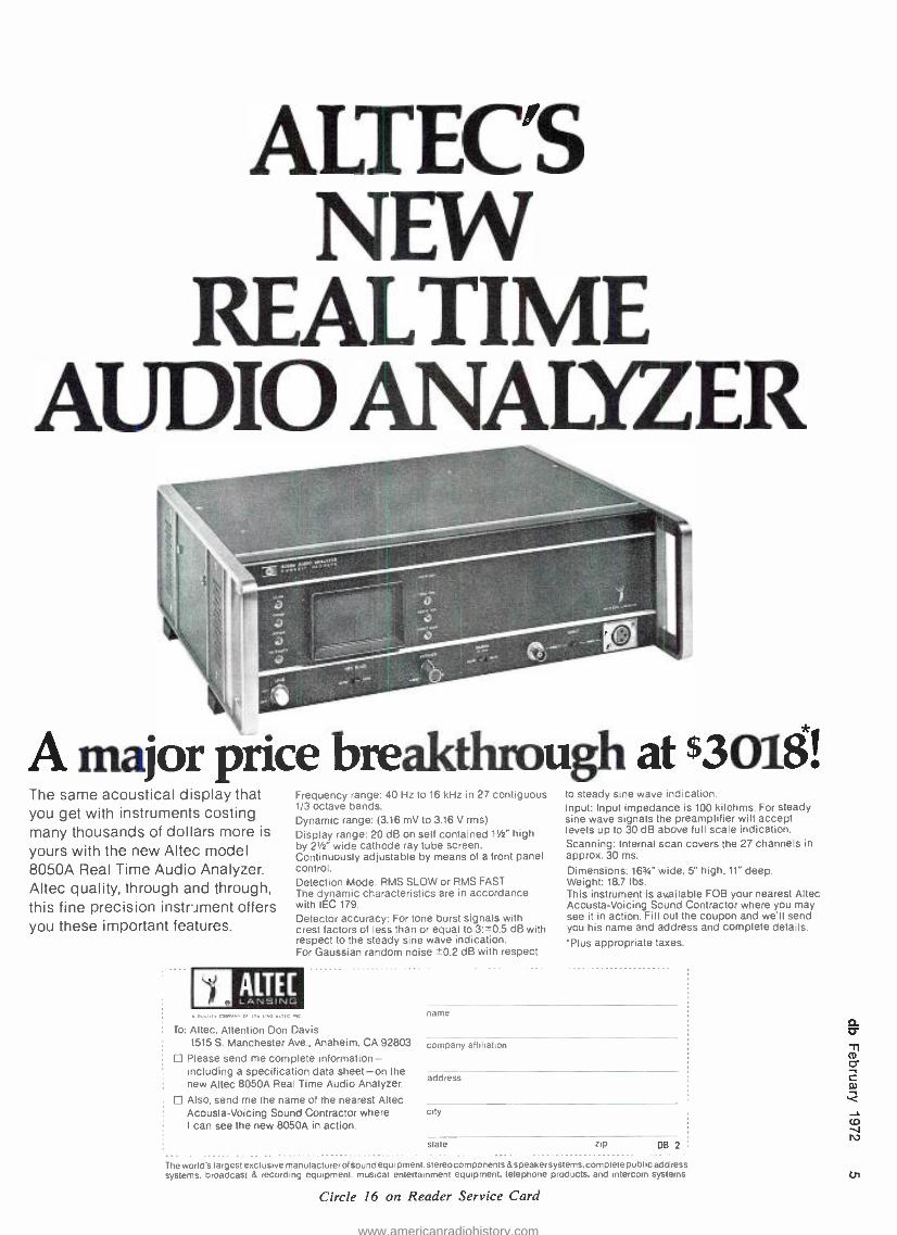
ALTEC'S NEW
REALTIME AUDIO ANALYZER
A major price breakthrough at $3018! The same acoustical display that you get with instruments costing many thousands of dollars more is
yours with the new Altec model 8050A Real Time Audio Analyzer. Altec quality, through and through, this fine precision instriment offers you these important features.
Frequency range: 40 Hz to 16 kHz in 27 contiguous 1/3 octave bands. Dynamic range: (3.16 mV to 3.16 V rms)
Display range: 20 dB on self contained 1' /2" high by 2' /s" wide cathode ray tube screen. Continuously adjustable by means of a front panel control. Detection Mode: RMS SLOW or RMS FAST The dynamic characteristics are in accordance with IEC 179.
Detector accuracy: For tone burst signals with crest factors of less than or equal to 3: ±0.5 dB with respect to the steady sine wave indication. For Gaussian random noise ' -0.2 dB with respect
ALTEE LANSING
To: Altec, Attention Don Davis 1515 S. Manchester Ave., Anaheim, CA 92803
Please send me complete information - including a specification data sheet -on the new Altec 8050A Real Time Audio Analyzer.
Also, send me the name of the nearest Altec Acousta- Voicing Sound Contractor where I can see the new 8050A in action.
to steady sine wave indication. Input: Input impedance is 100 kilohms. For steady sine wave signals the preamplifier will accept levels up to 30 dB above full scale indication. Scanning: Internal scan covers the 27 channels in approx. 30 ms.
Dimensions: 163/4" wide, 5" high. 11" deep. Weight: 18.7 lbs. This instrument is available FOB your nearest Altec Acousta- Voicing Sound Contractor where you may see it in action. Fill out the coupon and we'll send you his name and address and complete details. 'Plus appropriate taxes.
name
company affiliation
address
city
state zip DB 2
The world's largest exclusive manufacturerol sound equipment: stereocomponents& speakersystems. complete public address systems, broadcast & recording equipment, musical entertainment equipment, telephone products, and intercom systems.
Circle 16 on Reader Service Card
CJi
www.americanradiohistory.com

NE -11_ 525
IN
REL MODE
2 L
"4 O-s OFF
e 12
te 0 CEILING
Model 525C
COMPRESSOR- LIMITER
Switchable Compression and Limiting functions Ceiling control for 20 dB of compres- sion or limiting De -Ess switch (Anti Sibilance) Four selectable release time ranges Fast attack time Integral illuminated meter In -Out switch, Threshold and Output level controls Frequency dependent release times Low distortion, less than 0.5% 30 to 20,000 Hz
Transformer coupled output to +24 dBm Stereo interconnection Utilizes Automated Processes 2520 Op Amps Panel mounting 11/2" x 51/4"
Designed for individual channel use where quality, stability and ease of op- eration are of paramount importance, the extreme flexibility, repeatable per- formance and stereo interconnect features of the Model 525C make it ex- traordinarily suited for all studio appli- cations.
The unique Ceiling control permits one knob control of compression or limiting in 2 dB steps over a 20 dB range while maintaining a constant out- put level.
The four Release Times, D -S feature, Mode of Operation and In -Out functions are controlled by positive action push button switches that can be rapidly operated.
Virtually all types of program mate- rial can be controlled with great con- sistency by the 525C without annoying side effects...DYNAMICALLY!
AUTOMATED PROCESSES/NC-
35 CENTRAL DRIVE FARMINGDALE, N.Y. 11735
516- 694 -9212
Circle 13 on Reader Service Card
recorded or does it appear only when the machine is in a playback mode?
What I am trying to say is that one has to act as a Sherlock Holmes, gath- ering all the facts about the malfunc- tion, even if you have to start check- ing all the circuits yourself in order to complete the picture.
It is impossible to easily teach somebody how to troubleshoot effec- tively, but one can be helped if he is told what to look for. I am going to divide symptoms into separate para- graphs and list all possible causes that come to mind.
Hum. Possible causes are: discon- nected shield, defective power supply, audio transformer proximity to the low level wire to the power line. In mechanical systems, the cause may be the rumble from the turntable motor appearing as a hum, or vibration of the building registered as a rumble and taken for hum. Air -conditioning noise or pulsation can affect the micro- phones and can be mistaken for hum.
Cures for hum problems consist of repairing the power supply, moving of system components, grounding of the shield, shock -mounting the turn- table. When microphones pick up air - conditioning noises, the use of direc- tional mics or installation of dampers in the ducts will alleviate the problem.
Motorboating. This problem is gen- erally associated with the power sup- ply problems, especially when high - gain class AB amplifiers are in the system. Insufficient decoupling or high source impedance power supply is usually the cause. Less frequent cause is high- frequency oscillations produc- ing instability at low frequencies.
Cures are; increased decoupling be- tween the parts of the system by in- creasing decoupling capacitors, check output impedance of the power supply by measuring the voltage drop when a maximum load is connected - and then knowing the load impedance cal- culate using Ohms law. Source impe- dance of a few ohms generally means trouble. Typical readings should be in fraction of an ohm. Adding capaci- tance across the power bus may help. With the power supply having remote sensing -use it. This will shift the lower impedance point closer to the load. Also, check phasing of the signal at the low end as well as for the low - frequency response, if it extends below the useful range.
Frying noise. Frying noises are usu- ally an indication that one of the semi- conductors is defective or some resis- tor is overheating from the excessive current through it. Also partial de- modulation of an r.f. signal may be mistaken for frying noise.
In a system, cure for frying noise should consist of isolating and re-
placing the defective amplifier or com- ponent. In an amplifier the cause of the failing resistor or transistor has to be found before the unit can be put back into operation, since the unit will fail again (possibly with more disas- terous results causing more damage). Just replacing defective part without finding the cause won't do.
Pops and clicks. We should distin- guish between pops and clicks de- tected in the system when no switch- ing is done (susceptibility of the sys- tem to pickup transients originated by the equipment in the vicinity or in the same building) and the clicks pro- duced when switching is done in the system. In the first case the cause (and consequent cure) are almost the same as for the hum problem- improper shielding or grounding, insufficient de- coupling or poor filtering in the power supply, as well as unshielded and extra long sensing wires from the power supply to the load.
Cure in this case also consists of adding line filters if all the above - mentioned faults are corrected or brought under control without improv- ing the condition. One of the best generators for testing the system for susceptibility to pops and clicks is usu- ally an electric shaver or electric drill. They produce more transients than the vacuum cleaner or elevator do.
If the pops and clicks are a func- tion of switching, the following could be the cause for it: no noise sup- pression of the relay coils, tape start or stop switches have no arc suppres- sion capacitors across the contacts, in switching audio there is d.c. on the switch, change of termination value in the directly -coupled amplifier. In a correctly- designed system there should be no reason for expecting clicks or pops, but sometimes electrolytics be- come leaky and d.c. get on the switch contacts. Or additions and modifica- tions of the circuit are made without incorporating noise- suppression com- ponents.
Oscillations. Causes: high gain, loss of grounding or shielding, phase re- versal, loss of power supply regula- tion, or proximity of low -level lines to the high -level lines or conductors.
Cures are more or less self explana- tory. When testing for phase shift or reversal, connect a diode across the terminals of the signal generator, then note, which peak of the sine wave is clipped, upper or lower. Follow with a scope through the system look- ing for the identical scope picture. If the clipped portion of the sine wave shifts from the bottom to the top or vice versa you have phase reversal. Before changing anything check the di- agram because one phase reversal may be of necessity followed and corrected
www.americanradiohistory.com

by another. Today, when most of the mixing is active (that is, operational amplifiers, are being used as summing amplifiers), phase reversal is to be ex- pected. This reversal is usually fol- lowed by another reversal in the out- put transformer.
Crosstalk. Causes range from im- properly aligned tape recorder heads, a defective power supply, poor ampli- fier decoupling, defective summing amplifiers, to missing terminations.
Cure consists of using the process of elimination- working initially with two channels, feeding signal first into one channel at operating level and measuring the output in the other channel. While measuring crosstalk, manipulate faders of both channels to determine which part of the circuit initiates crosstalk and which is picking it up. Check, using the scope, for audio signal in the power line. This may indicate if the trouble is in the power bus. In a tape machine, before you start realigning heads make sure that all your assumptions that the fault is there are correct. Check patch - bays, you may have something patched in that causes crosstalk.
Distortion. Possible causes include low supply voltage, voltage imbalance -especially in bipolar supplies, im- proper distribution of gain (levels), high- frequency oscillations, improper bias on the tape machine, faulty am- plifiers.
Except for the distribution of gain, all cures are part of the standard troubleshooting routine. If the sche- matic doesn't specify the gain set- tings, the following should be a good rule of the thumb: Set the operating levels as close as possible to 10 -15 dB below the clipping point of the stage. This will assure you good noise, low distortion, and crosstalk.
Low output. Sometimes, faults which show no obvious malfunctions as far as distortion or noise are con- cerned can be harder to find than completely dead circuits.
Causes for low output can be par- tially shorted or open circuits, im- proper patching or termination, and (believe it or not) high humidity. 1
have noticed that in in some opera- tional amplifiers gain can be affected by the leakage across the circuit board terminals. Especially if f.e.t.'s are in
,the circuit. Cure of this leakage consists of dry-
ing the boards and then covering them with a thin coating of a clear lacquer spray such as Krylon. Stay clear of contacts and controls. In order to de- termine which part of the circuit is at fault, follow the same procedures as suggested before -test the levels at each stage and compare them with
Son of U47
It looks a lot like the old man. What a mike he was. What presence. What a
shame he had to go. From 1947 to 1960, the U 47 revolutionized the
recording and broadcasting industries. And now his kid has arrived on the scene.
The U 47 fet. Its subjective quality is unchanged, because its
head enclosure is just as it was twenty -five years ago. (You see, it's primarily the shape of
the grille that gives a microphone its unique sound, and the demand for the U 47's distinctive sound has never slackened.)
What's new about the U 47 fet? Everything that 1972's state -of- the -art makes possible -op amps and all! It is protect- ed against wind and pop interference. Its capsule is elastically mount- ed to isolate it from mechanical shock disturbances.
The U 47 fet features both a 10 dB overload protection switch at the input of its internal electronics and a 6 dB switchable output pad to permit matching to highly sensitive microphone input circuits. A low - frequency roll -off is provided by a third switch. It goes without saying that the U 47 fet features compatible "Phantom "® powering. But it's hard to believe that it has a dynamic range of 136 dB, as compared to the old man's 86 dB. That's 50 dB wider!
The result: a great new microphone that adds lustre to a great old reputation.
The old man would have been proud.
For additional information, call or write:
11 A AUDIO CORPORATION
2 West 46th Street, New York, NY 10036 (212) 265 -4111 1710 N. LaBrea Avenue, Hollywood, CA 90046 (213) 874 -4444
In Canada: J -Mar Electronics Ltd.
Circle 17 on Reader Service Card
www.americanradiohistory.com

This won't save your heart
But a gift to the Heart Fund will provide more medical knowledge to protect your heart and the hearts of those you love.
GIVE ... so more will live
HEART FUND
Conlribuled by the Publisher
presents the new RPIO -12
PROFESSIONAL EQUALIZER for RECORDING and PLAYBACK PERFECT tailoring of octave -wide bands...Infinitely variable adjustment flexibility
...Special Effects programming ... Instant re- setting
7KOX HIIn.
t
via Computone- Charts
$349.50 eae.neódrea.R WpnL
Recording Studios Audiophiles Night Clubs Performers Theatres
Churches Gyms Auditoriums Hi -Speed Duplicating. Musical Groups
SPECIFICAT IONS ,Rro
án -,. ,rom 20.20.480 z down 8 10HT,
r0.1 40
9 n ,a 1CO RRt. :° @ IV..O5% 1v. Tyy: % 8 1v. e0ti6%MÌV %®1V.Typ:.o1%iV'
fiiÚ MÖ x5[ÉAO:B^lrereAa0n9Ú06Mlew2VeulWt.TÓtSÌOÓxenm, .r':ópo 7e'm 7:D:7,3.M;,.. i.i.mp. OUTPUT
de,,. ÌÓÑ LÓSSRÌÌn (Y,de c0nlmi. centered. and'roOTPUT ADJUST.' control a "0utput."
MA[IMMWIPÌIT lnmroAb;mpdance.3.3v;nro600enmm-fl3CBm).
SPECIAL FEATURES VU METER: Pre, ;Nen 8 . S% meter maeement pro.,eee e
INDUCTORS: TORS: To,mdall and Shielded ferrite-core. matcpn[
grade CIRCUIT
BOARDS, Militar RESISTORS: Low.nena selected earnon.61m throu`hout. SWITCH CONTACTS: Gold-plated to risa,s low nona and reliability. OUTPUTSWITCH:
S: C1
lsOI ; sentinuou:iy Equalizer ë from
aaaa:ITUit. dB. to match output to input.
6Ó Ì2Ó 1240.i0Ó. 960. Ì92Ó 36.Ó.t766Ó andt15 3centered at 30.
SISE: Walnut.ereined wop0 eau 5%' a lfr .11'. RaVICpanel 5I/- a 19'.
SoundcratMoen: 1310 E. W0Rellam AV... Senta And C.. 92305 Pp: 714.0364375
Circle 21 on Reader Service Card
the prescribed values. Make sure when you do this, that all compressors, lim- iters, and equalizers are set in the off position. Quite often you may have an equalizer set at -10 dB position at low frequencies and it just happens that the generator is also set for 100 Hz instead of 1000 Hz. You then assume that you have a low gain problem.
Poor frequency response. This is one of the most familiar problems of almost every type of system. It can be the result of an impedance mis- match, a shorted or open circuit, improper level setting, head alignment in the tape machine, extra long shielded wires or a poorly oriented knob on the equalizer.
As far as impedance mismatch is concerned, some circuits require proper termination or they may exhibit either high- frequency boost with in- sufficient loading (transformers), or high- frequency droop with excessive loading. Passive equalizers are also impedance sensitive. Long shielded wires from a magnetic cartridge will roll off high- frequency response (don't use more than 100 pF of cable capaci- tance for a 50k ohm cartridge). In- sufficient low- frequency response can be the after effect of a failing elec- trolytic on the input with consequent insufficient capacitance.
What I have just written is only a small part of what can be said about the problems of troubleshooting. You can not miss the constant appearance of magazine articles discussing special- ized troubleshooting. I think that we should attempt to do the same for the audio field. If those of you with prob- lems and questions will write to me, we can discuss them openly for the benefit of all. Naturally your name and affiliation will not be revealed un- less you wish it. Send me sketches, drawings, notes, curves -anything that may pertain to your problem and will help me give you advise or a possible solution to your problem. Don't ex- pect me to solve all problems from my desk, but I will do my best to be of use to those who need my help. You will help yourself as well as others.
moving Have you sent us a change -of- address notice? It takes time for us to change your plate so let us know well in advance of your move. Be sure to send us the complete new address as well as your old address. Include both zip numbers. Keep db coming without interruption!
www.americanradiohistory.com

you write it Many readers do not realize that they can also be writers for db. We are al- ways seeking good, meaningful articles of any length. The subject matter can cover almost anything of interest and value to audio professionals.
Are you doing something original or unusual in your work? Your fellow audio pros might want to know about it. (It's easy to tell your story in db.)
You don't have to be an experi- enced writer to be published. But you do need the ability to express your idea fully, with adequate detail and information. Our editors will polish the story for you. We suggest you first submit an outline so that we can work with you in the development of the article.
You also don't have to be an artist, we'll re -do all drawings. This means we do need sufficient detail in your rough drawing or schematic so that our artists will understand what you want.
It can be prestigious to be published and it can be profitable too. All arti- cles accepted for publication are pur- chased. You won't retire on our scale, but it can make a nice extra sum for that special occasion.
The annual Midwest Acoustic Con- ference will be held Saturday, April 15, 1972 with the broad theme "Four Channel Sound Reproduction, Crea- tion and Re- Creation of a Sound Field." The all -day meeting will be held in the Auditorium of the Tech- nological Institute of Northwestern University in Evanston, Illinois. Pro- fessionals and non -professionals in- terested in sound reproduction are in- vited.
The conference is held annually in the Chicago area under the auspices of the Chicago regional chapters of the Acoustical Society of America, the Audio Engineering Society; the Audio and Electro Acoustic Group of the IEEE and the Chicago Audio and Acoustics Group.
The tentative program outline calls for a 9 a.m. start under the chairman- ship of Daniel Queen, acoustics con- sultant and head of Daniel Queen As- sociates.
A discussion on What is Ambiance? is scheduled for 9:30 a.m., under the chairmanship of Marvin Camras, se- nior scientific advisor, I.I.T. Research Institute. John Volkman is scheduled on the panel.
Bruno Staffen, applied acoustics consultant for the consumer products division of Motorola, Inc. will be
chairman of the session convening at 11 a.m. Subjects for this meeting will include Reproduction in Rooms and Physical and Psychoacoustical Con- siderations. Roy Allison of Acoustic Research and Dr. Amar Bose (Bose Corp.) are panelists.
Following lunch, James Cunning- ham, Eight Track Recording Corp. of Chicago will chair a 1:30 p.m. session on Recording for Ambiance and Ef- fect. John Eargle and Bill Putnam are panelists.
James Kogan, vice president and director of research, Shure Bros., Evanston, Illinois, will lead a 3:15 p.m. meeting on Recorded Media and Discrete vs. Matrix Format. Duane Cooper, Warren Eisem, and Howard Durbin are panelists.
Demonstrations of four -channel sound reproduction will take place at 7 p.m. following a dinner at 5:30 p.m.
It should be noted that the panelists listed are from a tentative list that will be augmented. Information on the conference may be obtained from the president of the Midwest Acoustic Con- ference's Executive Committee, Mr. Daniel Queen. He may be reached at Daniel Queen Associates, 5524 West Gladys Avenue, Chicago, Illinois 60644. His telephone is (312) 261- 5738.
The OlIve Serles 2000 Console.
o.
Everything you want from a console ,today.
Everything you'll want from a Consoletomorrow.
olive C Olive Electro Dynamics Inc 2670 Paulus Montréal 386, Québec Canada (514) 332 -0331 Cable Olivet, Montréal
Westlake Audio Inc 6311 Wilshire Blvd Los Angeles, California 90048 (213) 655 -0303
Harvey Radio Company 444 Madison Avenue New York, N.Y. 10022
(2121 582 -1500
Studio Supply Company 112 Cloverdale Court Hendersonville, Tenn 3 7075 (615) 824 -5402
Studio- Technique 4 avenue Claude Vellefaux Paris (10e) France 206 -15- 60/208 -40 -99
Circle 23 on Reader Service Card
CO
www.americanradiohistory.com
Norman H. Crowhurst
THEORY AND PRACTICE
To pursue the problems of con- trolling bias in transistor circuits, con- sider the circuit shown in FIGURE 1. The 20 -ohms load is a nominal rep- resentation of the base input resistance of a next stage, which is not a con- stant resistance. But giving it a value of 20 ohms enables us to do some figuring.
Assume the beta of each transistor is 100. Using the collector to base bias, this makes the second transistor look
like a d.c. resistance of 2.2k divided by 100, or 22 ohms. In series with the collector resistor of 100 ohms, the 12 volt supply divides approximately into 10 volts across the 100 ohms and 2 volts across the transistor. The tran- sistor current is determined by 10 volts across 100 ohms, at 100 milliamps.
The base bias current is about 1
milliamp. When feeding into a 20 -ohm load, increasing base current to 2 milliamps will make collector current
TIMEKEEP k ..
THE XEDIT -2 the finest 2" tape splicing block you can buy
Small holding ridges will not crimp the tape when it is removed Razor blade fits snugly -makes a straight, neat cut Tough aluminum alloy with clear, anodized finish Custom- machined to extremely close tolerances Cork backing -no slippage 7 "x3 "x3/4"
Sold exclusively by TIMEKEEPER on a 100% money back guarantee. You must agree that this is the best 2" tape block you have used or you may return the unit for a full refund.
N.Y.S. residents add 6% sales tax Price: $80. postpaid (45° cut is optional at 55 additional)
TI M EKEEPEß P.O. Box 835 Great Neck, N.Y. 11021
200 milliamps, of which 120 milliamps flow through the 100 ohm resistor and 80 milliamps through the 20 -ohm re- sistor. Going up to 2.2 milliamps will saturate at 220 milliamps, with 120 milliamps through the 100 ohm and 100 milliamps through the 20 ohm.
In the reverse direction, when base current is cut off, all the 100 milliamps through the 100 ohms is momentarily shunted through the 20 ohms as well. The coupling capacitor averages out the a.c., so that the flow of 100 milli - amps each way through the 20 ohms maintains the balance. Taking a quick look at the first stage, if its beta is 100, the transistor will look like a d.c. resistance of 220k divided by 100, or 2.2k. This, in series with the collector resistor of 4.7 puts 3.8 volts at the collector, with about 1.75 milliamps.
This should enable this stage to de- liver ±-1.75 milliamps to the base of the second stage, without difficulty. As it only needs ±1 milliamp, or maybe slightly more, so far so good. But let us consider three possibilities of varia- tion. (1) if beta changes from 100 to 70 or 140; (2) if the output load of 20 ohms changes; (3) if the input drive reaches the full 1.75 milliamps available from the first stage.
If beta of the second stage changes from 100 to 70 or 140, the d.c. re sistance of the transistor changes from 22 ohms to about 32 ohms or about 16 ohms respectively, so that collector voltage changes from around 2, to around 3 or 1.5 volts respectively. The stage still works, although maybe not at optimum to deliver maximum cur- rent into the 20 -ohm load.
If the 20 -ohm resistance drops below 20 ohms, the voltage developed across it will drop, but the current swing will not be changed materially. The improper things happen if the 20 ohms runs high. Suppose it comes off
www.americanradiohistory.com
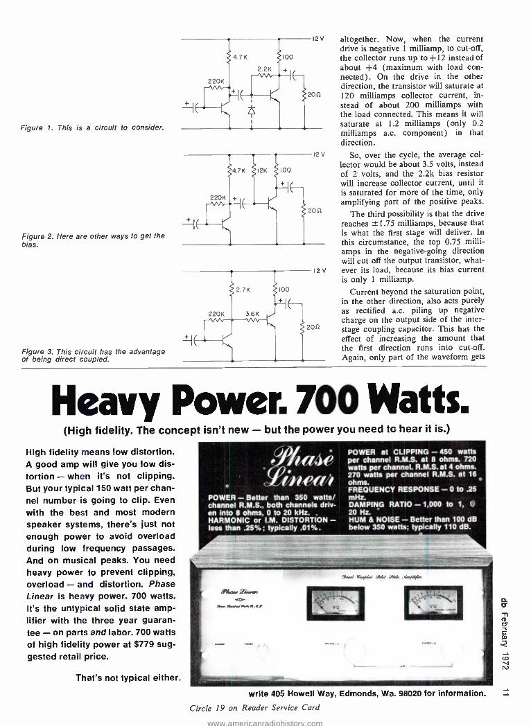
Figure 1. This is a circuit to consider.
Figure 2. Here are other ways to get the bias.
Figure 3. This circuit has the advantage of being direct coupled.
altogether. Now, when the current drive is negative 1 milliamp, to cut -off, the collector runs up to +12 instead of about +4 (maximum with load con- nected). On the drive in the other direction, the transistor will saturate at 120 milliamps collector current, in- stead of about 200 milliamps with the load connected. This means it will saturate at 1.2 milliamps (only 0.2 milliamps a.c. component) in that direction.
So, over the cycle, the average col- lector would be about 3.5 volts, instead of 2 volts, and the 2.2k bias resistor will increase collector current, until it is saturated for more of the time, only amplifying part of the positive peaks.
The third possibility is that the drive reaches ±1.75 milliamps, because that is what the first stage will deliver. In this circumstance, the top 0.75 milli - amps in the negative -going direction will cut off the output transistor, what- ever its load, because its bias current is only 1 milliamp.
Current beyond the saturation point, in the other direction, also acts purely as rectified a.c. piling up negative charge on the output side of the inter - stage coupling capacitor. This has the effect of increasing the amount that the first direction runs into cut -off. Again, only part of the waveform gets
Heavy Power. 700 Watts. (High fidelity. The concept isn't new - but the power you need to hear it is.)
High fidelity means low distortion. A good amp will give you low dis- tortion - when it's not clipping. But your typical 150 watt per chan- nel number is going to clip. Even
with the best and most modern speaker systems, there's just not enough power to avoid overload during low frequency passages. And on musical peaks. You need heavy power to prevent clipping, overload - and distortion. Phase Linear is heavy power. 700 watts. It's the untypical solid state amp- lifier with the three year guaran- tee - on parts and labor. 700 watts of high fidelity power at $779 sug- gested retail price.
That's not typical either.
POWER - Better than 350 watts/ channel R.M.S., both channels driv- en into 8 ohms, 0 to 20 kHz. HARMONIC or I.M. DISTORTION - less than .25 %; typically .01 %.
POWER at CLIPPING - 450 watts per channel R.M.S. at 8 ohms. 720 watts per channel. R.M.S. at 4 ohms. 270 watts per channel R.M.S. at 16 ohms. FREQUENCY RESPONSE -0 to .25 mHz. DAMPING RATIO - 1,000 to 1, Cò
20 Hz. HUM & NOISE - Better than 100 dB below 350 watts; typically 110 dB.
write 405 Howell Way, Edmonds, Wa. 98020 for information.
Circle 19 on Reader Service Card
www.americanradiohistory.com

db binders only $4.95 postpaid
Heavy- weight binders are now available to hold the thirteen issues of Volumes I and 2. Rich brown leather- grained virgin vinyl, with our name printed in black on the spine and front cover, is electroni- cally sealed over rigid board to give your volumes of db lasting protec- tion. Keep your copies preserved in perfect condition, protected from dust and damage.
EPlease send me copies of, the db Magazine binder. My check for $ is enclosed (sorry, no c.o.d.). Name Address
number and street
city state zip
(New York State residents please add 6% sales tax).
Mail to: db the Sound Engineer- i
ing Magazine, 980 Old Country Road, Plainview, N.Y. 11803.
THE NEW KM 88. UP CLOSE...
ATA DISTANCE There's a special bright- ness and an extra sheen to the sound of the new KM 88.
Qualities you've heard before -in the KM 56 tube model.
Like that popular earlier model, the KM 88 is the smallest three -pattern microphone made.
It is the only fet -80 Phantoms Powered mike whose dual membranes are made of nickel -the secret of its unique, characteristic sound.
The KM 88 permits distant pickup with close -up quality. (And it has a 10 dB overload switch, as usual.)
Progress can have a familiar sound.
For more information call or write:
GOT la r, AUDIO CORPORATION
2 West 16th Street. New York, NY 10036 (212) 265.4111 1710 N. LeBrea Avenue, Hollywood. CA 90046 (213) 874.4444
In Canada: J.Mar Electronics Ltd.
Circle 17 on Reader Service Card
amplified, but for a different reason. So let us look at some other ways of
getting the bias. FIGURE 2 uses a 12k from supply positive, instead of a 2.2k from collector. When beta is precisely 100, this will yield the same operating point for normal operation. For the second deviation, of removing the 20- ohm load, it will prevent the bias cur- rent from changing, because bias cur- rent will be held steadily at 1 milliamp (by 12k across 12 volts), come hell or high water.
But changing the beta will change the collect current from 100 milliamps to 70 or 140 milliamps. Actually 120 milliamps is saturation, with the 100 - ohm collector resistor, so the stage ceases to work when beta reaches 120. At beta of 70, the collector voltage rises from 2 volts to 5 volts, consid- erably reducing the available output swing into the 20 -ohm load.
We hardly need consider the effect of increasing the drive from 1 milli - amp to 1.75 milliamps a.c. peak. The output stage runs into saturation faster, because the self- correcting effect of the collector feedback is missing.
There is another factor: the effect on the dissipation of the second tran- sistor. The first circuit sets the operat- ing point at 2 volts 100 milliamps, which is a dissipation of 200 milli- watts. This would be safe for a tran- sistor rated at 300 milliwatts maxi- mum, although when the collector voltage rises to 3 volts, the dissipa- tion is 270 milliwatts, which is getting close.
However, with the biasing circuit of FIGURE 2, if beta drops to 70, collector voltage is 5, current 70 milliamps, a dissipation of 350 milliwatts. The mar- gin of safety has more than gone.
So let us look at the circuit of FIGURE 3. This has the advantage of being direct coupled, so that increasing the drive beyond ±1 milliamp will not cause overbiasing of the stage. It will merely over -drive the second stage on an instant -to- instant basis.
Assuming a collector voltage of 3.8 volts for the first transistor, the 3.6k coupling resistor passes about 1 milli - amp, which also passes through the collector resistor. This raises the cur- rent through the latter from 1.75 milli-
amps to 2.75 milliamps, requiring its value to be dropped from 4.7k to 2.7k to retain the same voltage drop. As the transistor still operates at the same collector current, the 220k bias resistor is unchanged in value.
Now, if the 20-ohm resistor changes in value, this does not change the bias of the output stage, although change in the beta of the first stage can change the bias of the second stage, by changing first stage collector voltage, at the "front end" of the 3.6k resistor.
And what about change in beta of the second transistor. Just like FIGURE 2, assuming that collector voltage of the first stage is fixed at 3.8 volts, bias current is fixed by the 3.6k resistor, as it was by the 12k resistor in FIGURE 2.
So, all in all, the circuit of FIGURE 1 seems best, except that the circuit of FIGURE 3 eliminates the time -con- stant of the interstage coupling capaci- tor. This can to some extent be rem- edied by using a suitable base to ground resistor. In some circuits it may have more benefit than here.
Assume the base to emitter voltage is 300 millivolts, with +100, -300, for the ±1 milliamp swing. This looks like from 100 to 300 ohms base input resistance. At cut -off, this suddenly rises almost to infinity, so that the only resistance to bring the circuit back to normal is the 2.2k from the collector. This is certainly better than the 12k of FIGURE 2.
Another trick that helps, by utilizing the drive beyond cut -off to discharge the rectified effect on the coupling capacitor, is to connect a diode across the base -emitter junction of the tran- sistor, shown dotted in FIGURE 1.
Possibly the best alternative, is to design the previous stage so that it is
incapable of delivering a 75 per cent overload drive current to this stage. If you raise the 4.7k collector resistor to 8.2k, with appropriate change in col- lector to base bias resistor, so collector current is about 1.2 milliamps, instead of 1.75 milliamps, with collector at about 2 volts, requiring 150k or I80k, the previous stage will only be able to deliver about 20 per cent overload current, which will have far less detri- mental effect.
attention overseas readers The slow delivery of each month's
issue to overseas addresses often re- sults in the return of reader service cards that have passed the date of their expiry. As the processing com- puter is trained to reject such cards, overseas readers wanting information
are not always receiving it. You should check the expiry date
on the reader service card. If the date is close, and you must allow the time for mail service back to the address on the card, we can only urge that air mail be used.
www.americanradiohistory.com

John M. Woram
THE SYNC TRACK
The letters continue to arrive at db Magazine, and at studios throughout the country, if the mail at Vanguard is any indication. "How do I become a recording engineer ? ", they ask. As many as possible get answered, but to respond to them all would be an al- most full time job.
And, what does one say by way of answering? Becoming a doctor or a lawyer is certainly easier (to describe, that is). Just go to school, get your diploma and open up an office. Next question.
The would -be recording engineer's path is not so clear, though it may be just as long. There are still no uni- versities offering courses leading to a degree in recording- studio engineering, which may be a very good thing,
come to think of it. To digress; my bride has a deep in-
terest in medicine. Now that the kiddies are almost as big as their parents, she has been working at the nearby nurs- ing home. She gets some satisfaction helping the aged through their endless last days. And she goes to the State University at Farmingdale in the eve- ning to take courses leading to an Associate in Applied Science degree in Nursing. She just passed her final in English Composition, which means she'll now be able to take Introduction to Literature when its offered. She'll be a fine nurse, providing she doesn't flunk Speech I and does well in her Sociology course. In the meantime, the patients can just wait a bit longer for better care. You certainly wouldn't
want your parents being touched by someone who couldn't tell a verb from a preposition would you?
Now, being an unlettered type my- self, (hardly, ed.) I would say, if I were asked, that any educational au- thority who insisted that an otherwise well -qualified person be prevented from functioning as a nurse until she got through Introduction to Literature et al, was either kidding, or criminally insane. If this same mentality had any- thing to do with the recording indus- try, can you imagine the drivel one would have to wade through in order to get a degree in recording?
There is certainly nothing wrong with a good liberal -arts education (I wish I had one). If you have the time, money, and inclination it is well worth the effort. But, if you want to make a living in the recording industry, you don't have to sweat English Compo- sition.
Perhaps the industry leans too far the other way. At times, there seems to be an actual suspicion of people with a degree. I'm not sure why this should be. Even if a degree does you little good, it certainly does you no harm. Unless it elevates you above the dirty work that is so much a func- tion of the recording world. Even if you really don't mind "shlepping" mic-
You can afford all this
if you cut just one
stereo side per day.
Lease the new Westrex DiskMaster system for less
than $1,500 per month. Cutting just one stereo side per day pays for all of it...the Westrex 3D11
StereoDisk recorder, new Westrex solid state drive system, automated Scully lathe, advanced Westrex mastering console, Scully T/M tape reproducer, and
complete monitor system.
Attract creative, discriminating customers with the superior, truly exciting performance of the new Westrex 3DI1 /solid state system. Select the complete DiskMaster system, a modernizing system designed around your present equipment, a supplementary basic system, or any unit. Purchase or 5 -year lease.
Westrex Stereo Disk Recorders: the first in use, still the first in quality.
WESTREX, 390 N. Alpine Dr., Beverly Hills, Cal. 90213 (213) 274 -9303 ® Westrex Litton
Circle 18 on Reader Service Card
New Westrex 3DII Recorde
www.americanradiohistory.com

Studio Technology and Practice
SURVEY OF RECORDING FUNDAMENTALS
A. Sound generation and propagation, simple harmonic motion, sine waves and music sources.
B. Hearing, dynamic range, loudness, masking, decibels.
C. Electrical fundamentals, ac circuits, RLC im- pedance.
D. Magnetic fundamentals, dynamic devices - mics., speakers, pickup cartridges, cutting heads, tape heads.
MAGNETIC TAPE RECORDING
A. Basic tape recording process, block diagram of tape recorder, introduction to high fre- quency bias.
B. Bias and erase adjustment, head alignment. C. Multi -track recording, remix consoles. D. Complete tape recorder alignment procedure.
STEREO DISK RECORDING
A. Disk groove geometry, lateral & vertical modu-
lation, mono & stereo grooves, groove ampli- tude & velocity.
B. Disk playback systems & standards, velocity & level, test records, magnetic & dynamic cutting systems.
C. Stereo /mono compatibility, automatic pitch and depth control, master, mother & stamper plating, pressing.
D. Test equipment -oscillators, voltmeters, oscil- loscopes, intermodulation & harmonic distor- tion meters.
MICROPHONES AND STUDIO CONSOLES
A. Lines -balanced & unbalanced, introduction to impedance matching, European & American systems.
B. Impedance matching, jack fields & patching, basic console layout.
C. Microphones and preamplifiers, noise consid- erations.
D. Limiters, equalizers and noise reduction equipment.
rophone cables, going for coffee, and cleaning up after the recording staff finishes, they may find it difficult to
accept. This is certainly not fair to the degree holder, but I'm afraid many studios have gotten stung by over-
Rupert Neve Incorporated SENIOR ENGINEER
Rupert Neve Incorporated, a world leader in Professional Audio Control Equipment, requires a Senior Engineer to locate in Southern Connecti- cut. The person we need will be able to interpret customers' require- ments and present them in the form of block diagrams and layouts. He will also be prepared to travel in the United States and Canada for the purpose of installation and commissioning of equipment. The successful candidate should be of graduate standing and prefer- ably have some experience in the audio industry. Salary will be in the middle teens.
Direction of the corporation and a segment of the business is devoted to the use of modern communication technology in the propagation of the Christian gospel in areas where traditional means are inappropriate. The successful candidate preferably should be able to associate him- self whole -heartedly with these objectives.
Qualified applicants are invited to submit resumes including a salary history and employment history to:
Rupert Neve Incorporated Berkshire Industrial Park Bethel, Connecticut 06801 Attn: Mr. David Neve, General Manager
All replies will be acknowledged and selected candidates interviewed in Bethel, Connecticut, during the months of February /March.
qualified help from time to time. There is no question that classroom
work could play an important part in the development of recording skills. In fact, several schools now offer an oc- casional seminar for those interested in learning more about recording. Yet, with the exception of the Institute of Audio Research here in New York City, few, if any, offer a continuing program of any considerable length.
The Institute of Audio Research was begun several years ago, in an attempt to provide classroom training directly related to the recording industry's needs. I've printed a typical working outline for one of the Institute's courses. Note the glaring absence of Introduction to Literature! With the exception of a few of the earlier ses- sions on acoustic and electrical funda- mentals, most of the classroom time is directly related to recording. And by a remarkable coincidence, I'm going to be meeting with the class during the present term in an effort to put class- room theory into practice during a few lab sessions in the studio. Later in the term, after some first -hand experience with the Institute's program, I'll be in a better position to report on its con- tribution to the recording industry, as I reinforce my somewhat shaky back- ground in theory, in exchange for whatever practical assistance I can contibute.
www.americanradiohistory.com

NEW PRODUCTS AND SERVICES
METER PANEL
A two -channel vu meter panel and attenuator is offered in this model VP- 1S. The unit is designed to monitor any two of twenty -four inputs simul- taneously. Standard input level is +4 dBm to +45 dBm dependent upon at- tenuation selection. Optional input preamps are available for levels down to 90 dBm (0 dBm). Attenuation se- lection is by four selection push but- ton and a 4 dB vernier control. The unit fits a standard 19 -inch rack. Mfr: Broadcast Automation Associates Price: $320 Circle 60 on Reader Service Card
L \
YIIIIYMM = = IIIIIIIIIIII
NOISE REDUCTION SYSTEM
Over 30 dB of noise reduction is claimed for the DBX 187, a four - channel noise -reduction system that decreases hum, hiss, and crosstalk in recordings. Straight -line decibel com- pression before recording and compli- mentary expansion in playback pro- vides perfect transient tracking with no pilot tone or critical level matching. Hiss and asperity noise at normal levels are reduced by 10 dB. Four channels of record or play are pro- vided. Mfr: DBX Inc. Price: $1950 Circle 62 on Reader Service Card.
MINI CONSOLE
The M675 broadcast production master when used in combination with a M67 microphone mixer provides a small size professional quality broad- cast console with cuing. There are four line inputs (two switchable to RIAA). Each input is controlled indi- vidually with each pot having a cue position. An internal speaker is built into the front panel as is a front -panel headphone jack. Using with an M67, the M675 provides (built -in battery power to both units as well as facility to feed the M67 to the M675 moni- toring circuits for program monitor. A rear -panel phone jack permits the user to monitor only program material. Mfr: Shure Bros., Inc. Price: $250 Circle 59 on Reader Service Card.
REVERB SYSTEM
Model BX -20E produces reverber- ation by the torsional vibration of a specially treated coil spring. The tor- sion elements consist of several units with microscopic and macroscopic variations of the line paramerer inter- spersed with controlled damping and supporting elements. Electronic damp- ing utilizing motional feedback, per- mits variation of the decay time from 2 to 4.5 seconds. The unit is a two - channel- allowing maximum flexibility in stereo or mono use. The two inputs may be paralleled and each channel used separately. Channel separation is 60 dB. Weight is 105 lbs., and dimen- sions in its case are 40- inches high, 17- inches wide, and 19- inches deep. Mfr: AKG Price: $2500 Circle 58 on Reader Service Card
HIGH FREQUENCY HORN
The RH60 is a glass -fiber high -fre- quency horn. The design uses a radial horn that has been selected and used in such a way as to provide a uniform dispersion pattern over its range in a horizontal plane. The glass -fiber ma- terial eliminates resonance and its epoxy finish will withstand consider- able abuse. The horn is moulded in one piece. Its throat is 2 inches in diameter and its flange is drilled for the large JBL drivers. Adapters are available that maintain the flare rate but reduce the throat size to 1343
inches for Altec drivers or 1 inch for the smaller JBL's. The horn itself weighs 11 lbs. and is drilled and bracketed for easy mounting. The flare cutoff frequency is 250 Hz. Mfr: Community Light and Sound Circle 61 on Reader Service Card. CJ1
www.americanradiohistory.com
CD
HIGH POWER AMPLIFIER
Recent advances in high -voltage silicon power transistor technology is claimed as part of the reason for the availability of this new two -channel amplifier. Continuous power output per channel into 8 -ohm loads is stated at 350 watts at any frequency from zero to 20 kHz. Power at clipping is further stated to be typically 450 watts continuous per channel into 8 ohms and 730 watts into 4 ohms, with power derated to 270 watts continuous per channel into 16 ohms. Frequency re- sponse is zero Hz to 0.25 MHz at 1
volt, direct coupled inputs. There are also "normal" inputs which cut off bass response at 10 Hz. Harmonic or i.m. distortions are less than 0.25 per cent, typically 0.01 per cent. Sensitiv- ity is 1.14 V for 350 watts at 8 ohms; with hum and noise 100 dB down. Input impedance direct coupled is 10 k ohms; 100 k ohms normal input. Mfr: Phase Linear, Inc. Price: $749 Circle 71 on Reader Service Card.
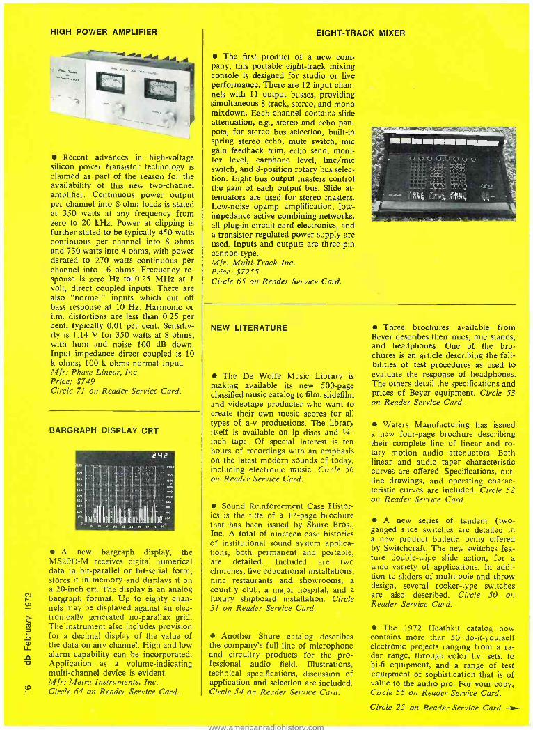
BARGRAPH DISPLAY CRT
SOO
StO
242
IIll 111 111 I(I( Ipf IIII Illf 111.111 III "°
A new bargraph display, the MS20D -M receives digital numerical data in bit -parallel or bit -serial form, stores it in memory and displays it on a 20 -inch crt. The display is an analog bargraph format. Up to eighty chan- nels may be displayed against an elec- tronically generated no- parallax grid. The-instrument also includes provision for a decimal display of the value of the data on any channel. High and low alarm capability can be incorporated. Application as a volume- indicating multi- channel device is evident. Mfr: Metra Instruments, Inc. Circle 64 on Reader Service Card.
EIGHT -TRACK MIXER
The first product of a new com- pany, this portable eight -track mixing console is designed for studio or live performance. There are 12 input chan- nels with 11 output busses, providing simultaneous 8 track, stereo, and mono mixdown. Each channel contains slide attenuation, e.g., stereo and echo pan- pots, for stereo bus selection, built -in spring stereo echo, mute switch, mic gain feedback trim, echo send, moni- tor level, earphone level, line /mic switch, and 8- position rotary bus selec- tion. Eight bus output masters control the gain of each output bus. Slide at- tenuators are used for stereo masters. Low -noise opamp amplification, low - impedance active combining -networks, all plug -in circuit -card electronics, and a transistor regulated power supply are used. Inputs and outputs are three -pin cannon -type. Mfr: Multi -Track Inc. Price: $7255 Circle 65 on Reader Service Card.
NEW LITERATURE
The De Wolfe Music Library is making available its new 500 -page classified music catalog to film, slidefilm and videotape producter who want to create their own music scores for all types of a -v productions. The library itself is available on 1p discs and 1/4- inch tape. Of special interest is ten hours of recordings with an emphasis on the latest modern sounds of today, including electronic music. Circle 56 on Reader Service Card.
Sound Reinforcement Case Histor- ies is the title of a 12 -page brochure that has been issued by Shure Bros., Inc. A total of nineteen case histories of institutional sound system applica- tions, both permanent and portable, are detailed. Included are two churches, five educational installations, nine restaurants and showrooms, a country club, a major hospital, and a luxury shipboard installation. Circle 51 on Reader Service Card.
Another Shure catalog describes the company's full line of microphone and circuitry products for the pro- fessional audio field. Illustrations, technical specifications, discussion of application and selection are included. Circle 54 on Reader Service Card.
Three brochures available from Beyer describes their mics, mic stands, and headphones. One of the bro- chures is an article describing the fali- bilities of test procedures as used to evaluate the response of headphones. The others detail the specifications and prices of Beyer equipment. Circle 53 on Reader Service Card.
Waters Manufacturing has issued a new four -page brochure describing their complete line of linear and ro- tary motion audio attenuators. Both linear and audio taper characteristic curves are offered. Specifications, out- line drawings, and operating charac- teristic curves are included. Circle 52 on Reader Service Card.
A new series of tandem (two - ganged slide switches are detailed in a new product bulletin being offered by Switchcraft. The new switches fea- ture double -wipe slide action, for a wide variety of applications. In addi- tion to sliders of multi -pole and throw design, several rocker -type switches are also described. Circle 50 on Reader Service Card.
The 1972 Heathkit catalog now contains more than 50 do -it- yourself electronic projects ranging from a ra- dar range, through color t.v. sets, to hi -fi equipment, and a range of test equipment of sophistication that is of value to the audio pro. For your copy, Circle 55 on Reader Service Card.
Circle 25 on Reader Service Card -ow-
www.americanradiohistory.com
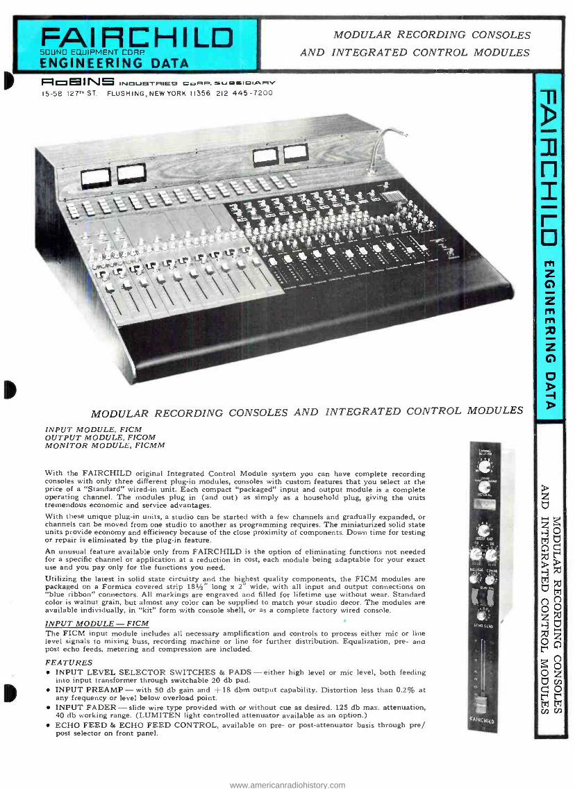
FAIRCHILD SOUND EQUIPMENT CORP
ENGINEERING DATA
MODULAR RECORDING CONSOLES
AND INTEGRATED CONTROL MODULES
FioEINS INOUBTRIE9 CORP. sU ss O1Á11'/ 15 -58 127T" ST. FLUSHING, NEW YORK 11356 212 445 -7200
MODULAR RECORDING CONSOLES AND INTEGRATED CONTROL MODULES
INPUT MODULE, FICM OUTPUT MODULE, FICOM MONITOR MODULE, FICMM
With the FAIRCHILD original Integrated Control Module system you can have complete recording consoles with only three different plug -in modules, consoles with custom features that you select at the price of a "Standard" wired -in unit. Each compact "packaged" input and output module is a complete operating channel. The modules plug in (and out) as simply as a household plug, giving the units tremendous economic and service advantages. With these unique plug -in units, a studio can be started with a few channels and gradually expanded, or channels can be moved from one studio to another as programming requires. The miniaturized solid state units provide economy and efficiency because of the close proximity of components. Down time for testing or repair is eliminated by the plug -in feature. An unusual feature available only from FAIRCHILD is the option of eliminating functions not needed for a specific channel or application at a reduction in cost, each module being adaptable for your exact use and you pay only for the functions you need.
Utilizing the latest in solid state circuitry and the highest quality components, the FICM modules are packaged on a Formica covered strip 181/2" long x 2" wide, with all input and output connections on "blue ribbon" connectors. All markings are engraved and filled for lifetime use without wear. Standard color is walnut grain, but almost any color can be supplied to match your studio decor. The modules are available individually, in "kit" form with console shell, or as a complete factory wired console.
INPUT MODULE - FICM The FICM input module includes all necessary amplification and controls to process either mic or line level signals to mixing buss, recording machine or line for further distribution. Equalization, pre- ano post echo feeds, metering and compression are included.
FEATURES INPUT LEVEL SELECTOR SWITCHES & PADS - either high level or mic level, both feeding into input transformer through switchable 20 db pad. INPUT PREAMP - with 50 db gain and +18 dbm output capability. Distortion less than 0.2% at any frequency or level below overload point. INPUT FADER - slide wire type provided with or without cue as desired. 125 db max. attenuation. 40 db working range. (LUMITEN light controlled attenuator available as an option.) ECHO FEED & ECHO FEED CONTROL, available on pre- or post -attenuator basis through pre/ post selector on front panel.
n z r D
www.americanradiohistory.com

MODULAR RECORDING CONSOLES AND INTEGRATED CONTROL MODULES COMPRESSOR - light- activated, distortion -free, providing 40 db dynamic range, 2:1 compression ratio. 6 milliseconds attack time maximum and variable release time. Variable compression. Overload protection above normal operating levels. FULL SPECTRUM PROGRAM EQUALIZER - switch controlled in 2 db increments, high and low frequency response. Feedback controlled with less than 0.2% distortion. No loss device. OUTPUT AMPLIFIER - with 40 db fixed gain, + 18 dbm output. Less than 0.2% THD. METERING - reference VU meter provided for monitoring input level, output level and compression. Resembles standard VU meter characteristics. CUE output can be provided on optional basis, allowing for audition of material processed through the module input to the fader without necessity of feeding mixing buss. SPECIFICATIONS Maximum Gain Maximum Output Load Impedance Output Source Impedance Input Impedances
Frequency Response THD IM Distortion Compressor
Equalizer
S/N Wideband Power Requirement
- 74 db (preamp gain 40 db, attenuator open, no compression) -+ 18 dbm into 600 ohm load, resistive or inductive - 150 ohms or higher -3 ohms (without transformer) - mic input - 200 ohms line input - 600 ohms Lower source impedances can be fed directly into these inputs -± 1 db 20 to 20kHz - 0.2% at 4 dbm. 0.5% max at 171/2 dbm - 0.2% maximum - Dynamic range 40 db. 2:1 ratio. Attack time 6 msec (3 msec typical). Variable release time 0.3 to 7 seconds - Low frequency: boost 10 db 50 Hz in 2 db steps
droop 10 db (^ 100 Hz in 2 db steps - High frequencies: 10 db boost at 2, 3, 4, 5, 7 and 10kHz in 2 db steps. 10 db droop max at 10kHz in 2 db steps. - 70 db or better with input level -50 dbm. - 24V DC with ripple 0.5 my p-p at 110 ma. FAIRCHILD 667II power supply recommended.
Handles up to 20 modules.
OUTPUT MODULE - THE FICOM The FICOM output module, companion to the FICM input module, contains all the components required for a high quality broadcast or recording channel. It provides necessary amplification and controls to process 0 db, - 20 db or - 40 db buss levels (so that, depending on the amount of loss encountered in the mixing networks applied, input to the module can be selected for proper signal processing), and +4 echo return level to a = -4 dbm output. The module includes equalization and compression, pre- and post echo return, metering and submaster attenuator, with provision for adding an external master attenuator if desired. Output of the FICOM can be fed into unbalanced line without transformer, or a transformer can be connected internally, isolating the module from external load. Echo return input and slating input are also provided. FEATURES
INPUT AMPLIFIER - amplification adjustable 25 to 50 db. Output capability +18 dbm with distortion less than 0.2 %. ATTENUATOR - slide wire type with 40 db expanded working range. Nominal attenuation 125 db. (LUMITEN light controlled attenuator available as an option.) ECHO RETURN - available on a pre- or post -attenuator basis, selected by pre /post switch on front panel. Echo return control selects desired amount of signal from echo or reverberation device. Accepts source impedances up to 1,000 ohms. COMPRESSOR - same as input module. FULL SPECTRUM PROGRAM EQUALIZER - same as input module. OUTPUT AMPLIFIER - same as input module. VU METER - small VU meter to monitor input level, amount of compression and output level. Resembles standard VU meter characteristics. SPECIFICATIONS Output Source Impedance Input Impedances
Frequency Response THD IM Distortion Compressor Equalizer Wideband Noise Power Requirement
- without transformer -3 ohms with transformer - 50 ohms -0 db input - 100K ohms - 20 db input - 10K ohms - 40 db input - 1000 ohms - Echo return - 750 - 1K ohms -T 1 db 20 to 20kHz - 0.2% at +4 dbm - 0.2% maximum - same as input module - same as input module - 70 db or better with an input signal of - 50 dbm and +4 dbm output - 24V DC ripple 0.5mv p -p at 110 ma. FAIRCHILD 667II power supply recommended. Handles up to 20 modules.
MONITOR MODULE - THE FICMM The standard monitor module is packaged on an 181/2" long by 4" wide strip and contains provisions for monitoring ten inputs, switchable between console or tape return. A 10 x 10 crossbar selector switch is included which enables monitoring of individual channels or any combination of channels. Gain controls for each monitoring channel are included. Facilities for controlling slating and talkback microphones are included. Microphone preamplifier, level control and key switch for selecting either function are contained. Relay muting prevents feedback during studio recording and playback. The FICMM monitor module requires 24V DC at 300 ma. CONSOLE SHELLS Shell to accommodate the 181/2" long by 2" wide integrated control modules are available in unwired form, and come complete with VU meter tier, all necessary XLR connectors in the -rear to accommodate desired number of channels. Channel plate for mounting mating "blue ribbon" socket assembly is included. Shells are constructed of aluminum covered in Formica to match or complement module color. Standard FICM shell is 203/4" wide by 231/2" deep and contains 20" of mounting space (accom- modating 10 FICM modules and /or spacers across). Other sizes available on request. VU meters are not included.
FAIRCHILD 5 UND EULJIPMENT C ORP FIoBINB 15-58 1279 ST FLUST I ING, NEW TORN 11356 212 945 -7200
www.americanradiohistory.com

AUDIO SPECTRUM ANALYZER
Model 8064A is a real -time audio spectrum analyzer - an instrument which measures and displays the fre- quency spectrum of sounds or vibra- tions as they occur. The unit can oper- ate as a stand -alone analyzer or as part of an automatic or semi- automa- tic data acquisition, data processing, or data recording system. Applications particular to the audio profession in- clude the ability to provide total analy- sis of room acoustic measurements on the spot. In short, its potential for value is so great, that we strongly sug- gest that you send for the data sheet that is available. Mfr: Hewlett -Packard Circle 72 on Reader Service Card.
18 IN, 8 OUT CONSOLE
Reduced price without sacrificed versatility and quality is claimed for this new console with 16 -track moni- toring system. Consoles can be speci- fied as to number and type of inputs, outputs, equalization, pan pots, mute and solo switches. At maximum, 18 input positions with two inputs each, mic or line, are accommodated. Mini- mum effort is required to change from tracking to overdubbing due to exclu- sive independent 16 x 4 monitoring system. Monitoring of any bus or track is possible with assignment to any or all speakers. Mfr: Quantum Audio Price: $5999 to $15,999 Circle 69 on Reader Service Card.
DOLBY -B RECORDER
The most recent versions of the A77 series recorders are now available with Dolby -B playback and recording circuitry built in. A total of four cir- cuits are used, providing separate play and record facilities. The Dolby cir- cuit is switchable in or out; there are built -in calibration controls and a ref- erence oscillator. A built -in multiplex filter protects the Dolby circuits from interferences and inaccuracies when recording off stereo f.m. Mfr: Re Vox Corp. Price: $200 additional to an A77. Circle 66 on Reader Service Card.
GAIN CONTROLLER
The GC 101 wideband gain con- troller is a two -quadrant trans- conduc- tance multiplier, divider, squarer, square rooter, and gain controller. It has the property of being able to con- trol gain over a 60 dB range with 0.1 dB accuracy (1 per cent) extremely low distortion, low noise, and wide frequency response. Specifications in- clude: response from d.c. to 12 MHz at unity gain, d.c. to 70 kHz at -60 dB gain; noise 130 mV r.m.s. in a 20 kHz bandwidth at unity gain and 6
r.m.s. at -60 dB gain. The unit delivers a voltage of ±10 at 10 mA. Harmonic distortion is typically 0.04 at 2 volts and does not increase at low gain. Mir: Burwen Labs. Price: $250 Circle 73 on Reader Service Card.
-4- Circle 25 on Reader Service Card
TURNTABLE SYSTEM
An electronically - controlled d.c. motor is used on the model PS 600 record playing system. A relatively small motor with low dynamic mass is
used to achieve low levels of motor vibration. An oil- hydraulic suspension system supports the turntable and arm mounts to reduce susceptibility to ex- ternal shock. The arm is balanced in all three planes and supported by ball bearings. Specifications according to DIN standards have rumble better than -65 dB and wow and flutter 0.07 per cent or better. The unit may be used as a manual single play, auto- matic single play, or multiple- record changer. Mfr: Braun Price: $269 Circle 70 on Reader Service Card. co
www.americanradiohistory.com

0 N
NEW! PANNING AND
SLIDERS ON A BUDGET
4 0 Y 0 ..
1-1 # 4 R A :;111111F EM -7S Four Input Stereo Echo Mixer
All features of our regular EM -7 Mixer plus slide pots, panning active mixing and IC circuitry. Duplicates all big board effects when used with ES -7 echo unit and PEQ -7 equalizer.
FOUR CHANNEL ACTIVE PEAKING TYPE EQUALIZER
-
PEQ -7 Four Channel Equalizer
Update your EM -7 system or use with new EM -7S Mixer. Five Hi freq. peaking type curves, 1.5, 3, 5, 10, and 20 kHz. Boost or cut in steps of 2, 4, 6, 9, or 12 dB. EQ in -out switch. Zero insertion loss.
GATELY ELECTRONICS 57 WEST HILLCREST AVENUE HAVERTOWN, PENNA. 19083 AREA CODE 215 HI 6 -1415 ...have you checked Gately lately ?
Circle 22 on Reader Service Card
AUTOMATION CONSOLE
This control center for broadcast automation has been introduced in several variations, each featuring slop- ing front consoles with a convenient writing surface. The control center programs music, random selects cart- ridge commercials, inserts station iden- tifications, and joins networks -all au- tomatically. It is stated to be compat- ible with all broadcast quality tape equipment. Mfr: Sparta Electronic Corp. Price: $6000 -$8500 (dependent on
options) Circle 57 on Reader Service Card.
VOLTAGE GAIN CONTROL
This potted module is designed as a voltage controlled gain device. Des- ignated the VCA -1, it is intended for use by equipment manufacturers in forthcoming automated control boards. The manufacturer states that it solves the performance problems of conven- tional multiplier circuits such as poor s /n, rising distortion as gain is re- duced, control -signal rejection, and low gain- tracking accuracy. Mfr: Allison Research Price: $50 per unit (OEM prices avail-
able) Circle 63 on Reader Service Card.
VARIABLE FILTER
A filter that is variable both at low and high frequencies has been intro- duced. The frequency points have been selected to provide an extended range of control. The low frequency 3 dB points are: 40, 55, 70, 85, 100, 150, 200, 250, 350, and 500 Hz. High fre- quency 3 dB points are: 15, 12.5, 10, 8.5, 7, 6, 5, 4, 3, and 2 kHz. Impe- dance is 600 ohms in and out; slope is 18 dB /octave, insertion loss is 0 dB in the pass band, and there is an in/ out level key. Mfr: Quad -Eight Electronics Price: $325 Circle 68 on Reader Service Card.
CROLYN CASSETTES
Audio cassettes using chromium di- oxide coated tape are now available. On properly equalized and biased re- corders, these cassettes can provide a significant increase in signal /noise and higher output at high frequencies when compared against standard ferric oxide formulations. The cassettes have been made available in C -60 and C -90 formats. Mfr: Memorex Circle 67 on Reader Service Card.
www.americanradiohistory.com

Martin Dickstein
SOUND WITH IMAGES
SMPTE Technical Conference This column will conclude the dis-
cussion on the October Conference of the Society of Motion Picture and Television Engineers. Last month, I covered the "Video Cassettes -Boom or Bust" discussion of Mr. Gordon Thompson of Bell- Northern Research Labs. of Ottawa, Canada. In addi- tion, there was coverage of Mr. J. Bernhart of the French National Tele- vision Office of Paris who discussed standardization attempts in the low - band video recording field. We go on now to other speakers of note with the reminder that my random selection is not intended to show favoritism nor is the editing of the remarks for ed- itorializing or personal comment or review.
In another technical session, Mr. Kazuo Iwama of Sony Corp. of Am- erica explained "The Design Concept of The Sony Color Video- cassette Total System."
Discussing the necessity of a new format, Mr. Iwama said "The half - inch format is the most familiar in the helical scan v.t.r. field. It could be very convenient for the user if the same format is maintained in the Videocassette and the player is fur- nished so that it can play on any standard open reel, as well as the cassette. But we have decided to de- velop a different format for the fol- lowing reasons:
"1. Utilizing the half -inch format prevents us from designing the Video- cassette in a reasonable physical size while maintaining a reasonable play- ing time. 2. Designing a mechanism compatible for both cassette and open reel is complex and unpractical. 3. High density tape, recently developed, can be introduced in a new format."
The details of the Sony system are given: "Our research and develop- ment experiments led us to decide on the tape width of 1/4 inch (19 milli-
meter). This tape width enables us to choose a tape speed of 95.3 milli- meters (approximately 31/4 inches) per second, which is quite reasonable for audio. The width of video track is 85 microns (approximately 3.3 mils) and the pitch is 137 microns (approx- imately 5.4 mils). Both are consider- ably smaller, but not too small to re- produce a signal of acceptable quality for recent technology. Scanning speed is 10.27 meters /sec. (approximately 404 inches /sec.), which allows us to maintain a bandwidth of 3 MHz for luminance, and 0.5 MHz for the chrominance signal. The tape is 27 microns (1.1 mils) thick, including coating, and stored in a cassette of 140 X 221 X 32 millimeter (51/2 X 81/4 X 11/4 inches) for full one hour operation. We believe that the cassette is extremely reasonable in size."
In the same technical session, Mr. Eric A. Yavitz of the Eastman Kodak Co., Rochester, concluded his talk on "Super -8 Film -A Universal Input to Video Cassettes and Television Sys- tems" this way: "Video cassette sym- posia give us a chance to look into the crystal ball and foretell the future. That is always an enjoyable exercise, although there is the danger of be- coming so enthralled with the future that one forgets the realities of the here -and -now, or the road that must be traveled to get from here to the future. I should like to conclude by returning to the here -and -now, and submit only one thesis for your con- sideration. Super 8 color film, the same film that is today increasingly widely used in the home, in industry and in the school - worldwide - is
from every aspect as viable in the future world of video cassettes as it is
in today's conventional display world, and perhaps even more so since it is the only system that can offer the user
the flexibility of bridging the gap be- tween these two worlds."
In a talk on "The Teldec Video Disc System," Mr. Walter Bruch of Teldec, Berlin, spoke of the Teldec equipment and the modifications introduced to the original Tripal process for color reproduction, and concluded his paper with: "The picture quality obtained with this version of Tripal is remark- able. From a normal viewing distance laymen will not observe a difference compared to a normal PAL transmis- sion. (Ed. note: PAL is the color t.v. transmission system used in Western Europe.) This goes for 99 per cent of all scenes and with reproduction on a large picture tube and is due to the chosen method of composing the mixed highs. The color fidelity of pic- tures coming from the video disc matches with that coming from a pro- fessional v.t.r. Only the definition is given by the video bandwidth of the signal coming from the disc, but this bandwidth has no influence whatso- ever on the chromaticity of the colors. The small amount of color noise is
amazing but due to the color being recorded and transmitted in the best part of the video transmission range.
"Thus Tripal M or Tripal D is a method which might be applied not only for the videodisc. For instance it is excellent for video -telephone con- nections, or especially in NTSC coun- tries, for the recording of television signals including color on narrow - band v.t.r.'s.
"A main advantage of the disc in comparison to helical scan magnetic video recorders is its capability to de- liver an uninterrupted signal. The sync pulses for controlling a time stabilizing circuit like Ampter, can always be operational. This gives the possibility of feeding, in a later stage of devel- opment, the picture into a studio mixer." N
www.americanradiohistory.com

PAUL C. BUFF
A Combination Limiter The author describes both the rationale and practical considerations that went into the design of a dual limiter product that his company manufactures.
THE NEED FOR LIMITING in profesional audio work has pretty much been established and is generally understood within the industry. This article will go a little beyond the basics to more closely ex-
amine the effects of limiting on complex waveforms and on apparent levels. The main topic of discussion will be the design and use of the new Allison Research limited, Gain Brain.
I feel it necessary however, to first furnish my list of definitions of some of the terms involved:
1. Instantaneous Peak Limiter: Commonly referred to as a "peak limiter" and defined as being a limiting device which is activated by the absolute peak value (positive or negative) of the input waveform, having a compression ratio greater than 10 to 1 and an attack time of less than 100 microseconds. Release time should be long enough to prevent excessive waveform distortion. If this is not the case, I would term the device a "clipper" rather than a limiter.
2. Compressor: A peak- activated device whose com- pression ratio is less than 10 to 1.
3. Averaging Compressor: Generally a misnomer ap- plied to a peak- activated compressor which has a relatively long attack time (on the order of one to ten milliseconds). While it does allow short duration transients to overshoot, it is not capable of reading the average value of a sustained waveform, hence the misnomer.
4. True r -m -s Limiter: A device whose gain reduction threshold is determined by the output of a true r -m -s de- tector circuit.
5. Quasi r -m -s Limiter: A device whose gain reduction threshold is determined by the output of a wave form average value detector circuit (whose output is approxi- mately equal to the r -m -s value of the input waveform).
Paul C. Buff is president of Allison Research, Inc. of Holly - cv wood, California
PEAK vs. APPARENT LEVEL First, let's take a look at why limiters are used at all. I think most engineers would agree that they are primarily employed for one or more of three reasons, these being:
1. To clamp the peak excursions of a program signal to a defined electrical level so as to not cause overdriving of succeeding stages in the audio chain.
2. To enable one to record or transmit a high and constant apparent level from program sources of varying level and content.
3. To enable one to modify the sound of a program by restricting its dynamic range. (i.e. a "limited sound ").
Let's go on to take a closer look at what's required of a limiter in order to best satisfy these objectives:
The first one is easy. We need a peak limiter with as fast an attack time as possible, as high a compression ratio as possible and release time variable to suit the content of the program.
The second situation, however, is a little more difficult. In looking at FIGURE 4, it can be seen that the electrical peak value of a waveform has no direct proportionality to its apparent level (as heard by the human ear and as read by the vu meter). If, indeed, the human ear measured the loudness of a sound by its waveform peak value, there would be no problem. We could use a peak limiter all the way around and expect to hear a constant volume regard- less of the shape of the waveform. That not being the case, let's see what really happens.
If you limit, say a flute and a saxophone, to the same peak level, both your ear and your vu meter will tell you that the flute is around 6 dB louder than the saxophone. This happens simply because the saxophone has a higher peak- to -r -m -s ratio than does the flute. If you force the peaks to be equal via peak limiting (fast or slow), you cannot expect the r -m -s energy (apparent level) to be the same. It's simple mathematics. The same peak r -m -s ratio situation holds true when dealing with any combination of complex music and speech waveforms. Obviously, a peak limiter is not the answer if one is to achieve a precise uni-
www.americanradiohistory.com

IN
CI
C2
DI
-8VDC C3
OUT
R3
RELEASE TIME
R4
Figure 1. An instantaneous peak detector. When the input signal exceeds the reverse bias applied to D1 and D2, they will conduct -charging C3 to a voltage equal to the peak value of the input signal minus 8 volts. Speed is limited by the impedance of the drive circuit and by diode speed.
formity of apparent level and neither is, what is sometimes referred to as, an "averaging compressor" (as described in my list of definitions.)
What is required is either a true r -m -s or quasi r -m -s
limiter. In such devices, the waveform is measured in terms of its effective power (or apparent level) before reaching the threshold determining network. Only by this, or similar methods may an accurate control of apparent level be realized.
It is, however, generally necessary that such a device be followed by a peak limiter since the very nature of an r -m -s limiter is to pass peaks without regard to their inten- sity. The threshold of the peak limiter must be adjusted so that, while it does control the peaks, it doesn't take control to such a degree that it overrides the effectiveness of the r -m -s limiter. Generally speaking, a peak limiter threshold around 6 to 8 dB above the r -m -s threshold (with respect to a sine -wave input) will prove effective. However, certain types of program material will be found to have an optimum separation of thresholds above or below this figure.
As for the third use of limiters (getting a "sound ") the type of limiting required is of course dependent on the sound which one desires to achieve. In general, the r -m -s
plus peak limiting approach described above will enable the engineer /producer to run the gamut of limited sounds through manipulation of the thresholds and release times.
THE GAIN BRAIN In the Gain Brain limiter, a combination of both instan- taneous peak limiting and quasi r -m -s limiting is em- ployed within the same device. The behavior of the device is similar to that which would be obtained by passing the signal first through a quasi r -m -s limiter and then through an instantaneous peak limiter. Referring to FIGURE 5, when the function control is rotated fully to peak position, the circuitry is such that the threshold point of both the quasi r -m -s detector and the instantaneous detector fall at the same point (with regard to a sine -wave input). Since the reaction time of the r -m -s detector is much slower than that of the peak detector, the device in this position will function purely as an instantaneous peak limiter.
Now, if the function control is rotated toward the r -m -s position, the relative threshold of the peak detector will move up while the r -m -s detector threshold will move down. When the function control is rotated fully toward the r -m -s
position, the circuitry is such that a 12 dB separation of
IN
1, o
CI
C2
DI
R5
-8 V DC C3
R3
RELEASE TIME
R4
OUT
Figure 2. A slow attack peak detector. This circuit func- tions as the one in Figure 1, except that the speed is limited by series resistor R5. Charge on C3 will still charge to a voltage equal to the peak value of the input signal minus 8 volts.
thresholds will result. By adjustment of the junction con- trol, in this manner, the Gain Brain can be made to behave as a pure peak limiter, a quasi r -m -s limiter, or as a quasi r -m -s limiter followed by a peak limiter.
Let us examine the operation of the device when the function control is in mid position (6 dB separation of thresholds). If the input signal is a sustained sine wave, only the quasi r -m -s detector will react, since its threshold is 6 dB lower than that of the peak detector.
Now, assume that a sharp transient spike appears at the input; only the peak detector will react for two reasons: I. The rise time of the spike is considerably faster than the attack time of the quasi r -m -s detector, so it will overshoot this threshold. 2. The peak- to- -r -m -s ratio of a
sine wave, exceeds 6 dB so the quasi r -m -s energy of the waveform is below the threshold point of the r -m -s
detector. Now, let's assume that the input is a sustained complex
waveform, having a relative peak- to -r -m -s ratio of 6 dB (a typical music wave -form). Both detectors will react,
Figure 3. A simplified quasi r -m -s detector circuit. D3, D4,
and Q1 are slightly forward biased by R1, Dl, and D2. Voltage across C3 is equal to the average value of the input waveform, with an integration time of t = R5 X C3. Q1 serves to amplify the voltage across C3. Q2 is reverse biased by 8 volts and serves as a unity gain phase inverter. When Q1 collector falls below + 16 volts, Q2 will conduct, causing D5 to conduct, charging C4. The resultant charge on C4 will equal the average value of the input wave- form (times the gain of Q1) (minus 8 volts and diode drop voltages of Q2 and D5).
IN
+24V. DC
+16V.DC
7 DI
7 D2
D4
OUT
RIO
RELEASE TIME
RI I
N w
www.americanradiohistory.com

VOLTAGE CONTROLLED
AMPLI FIER
N
SINE WAVE
SQUARE WAVE
FLUTE
DRUMS
HORNS
BASS
GUITAR
FALSETTO
VOICE
1 I l I' I l' I I T T 1 -20 -10 -7 -5 -3 -2 -I O +I +2 +3
Figure 4. Typical apparent levels of various program signals whose electrical peak levels are equal.
although the peak detector will react sooner than the r -m -s detector because of the attack time differences. Should the peak- to -r -m -s ratio be greater than 6 dB, only peak lim- iting action will result. Should it be less than 6 dB, only quasi r -m -s limiting will occur.
RESULTING PERFORMANCE The net result of the above, in terms of performance, is this: Gain Brain will attempt to limit the input program material according to its quasi r -m -s energy (or apparent level). However, should transient peaks or waveform peaks exceed a predetermined level (as governed by the function control) the device will revert to becoming an instanta- neous peak limiter (for the protection of succeeding stages in the audio chain).
Front panel l.e.d. indicators are provided to inform the user which detector is being activated (both may be acti- vated at the same time).
Generally, the most desirable results are obtained when both detectors are operating during the course of a pro- gram. Sustained simple waveforms then will cause r -m -s limiting, and complex waveforms and transients will cause peak limiting. In this manner, the apparent level of the program can be made considerably more uniform than with conventional limiters, while still maintaining an ab- solute control of peaks.
RELEASE TIMES Release times for limiting caused by both detectors are coordinated and controlled by a single front panel con- trol (release). In the maximum position, release is approxi- mately 5 seconds for limiting caused by either detector.
Figure 5. A sim- plified block dia- gram of the Gain Brain described in the text.
IN o
INPUT GAIN
In the minimum position, release time for peak-activated limiting is 50 milliseconds, but is on the order of 200 milliseconds for limiting caused by the quasi r -m -s detector. This results in the highly desirable characteristic of allow- ing a fast recovery to transient limiting while maintaining a longer release time for sustained program material. Such action is desirable in that it allows the program to appear at a high apparent level without excessive low- frequency distortion and pumping effects which normally would result from fast recovery operation.
ATTACK TIMES The attack time of the device (to instantaneous peaks) is extremely short, being less than 1 microsecond. In the laboratory, tests revealed no overshoot exceeding 1 dB within a 300 kHz bandpass, even when limiting a 50 kHz tone burst by 20 dB, with full recovery between bursts.
The circuity used to accomplish this extreme speed has still another desirable side effect. Ultrasonic transients which are less than 100 microseconds are limited with a release time on the order of 1 microsecond. This action allows such inaudible transients to be controlled without causing an audible gain reduction to occur.
The quasi r -m -s detector is activated with an attack time which is dependent on the waveform complexity but which typically falls in the 6 to 30 milisecond region.
METERING The standard vu meter, which is commonly employed as a gain reduction meter in limiters, has some pretty serious drawbacks; the worst of these is its inherently slow speed. Simply speaking, in fast recovery limiting situations, the gain reduction has come and gone before the needle can move. This doesn't allow very accurate readings. The second drawback, is the fact that a readable vu meter just doesn't fit into a 11/2-inch wide console module. (My how we've tried to make one work!)
The approach used in Gain Brain is to use a seven in- crement, sequentially activated, 1.e.d. array to accomplish gain reduction metering. Inherent l.e.d. speed is measured in nanoseconds. Readability is at least equal to that of a 4 -inch illuminated vu meter. Panel space required is ap- proximately 1/4 by 2- inches. Thanks to the sequential operation of the increments, an array of such meters does not cause the distracting light show effect or high current consumption of certain non -sequenced beam of light meters (where as many as 9 lights per meter may be on at one time). A further highly attractive feature of I.e.d's is the fact that the life expectancy of these devices is the same as any other semiconductor - virtually limitless.
OUT- PUT
F.GAIN
-0= PEAK INDICATOR
RMS INDICATOR
OUTPUT AMPLIFIER
FUNCTION" CONTROL
-0 OUT
ABSOLUTE PEAK
DETECTOR
COMBINING NETWORK
a RELEASE
TIME NETWORK
( R MS
'PEAK QUASI RMS DETECTOR
GAIN REDUCTION VOLTAGE
INCREMENTAL SEQUENTIAL
LIGHT EMITTING DIODE GAIN REDUCTION
DISPLAY
INTERCOUPLE NETWORK
STEREO O INTERCOUPLE
CONNECTION
www.americanradiohistory.com

ROBERT C. EHLE
Circuits for Synthesizing Multi -Channel In this article, the author describes experimental circuits that may be built from readily available parts. They may be used to synthesize additional channels from one- and two - channel sources.
THE CIRCUITS that are to be described include a method for synthesizing two -channel stereo from a mono source and several different techniques for producing four -channels from a two -channel
source. Techniques for synthesizing four channels from a mono source will also be discussed and illustrated and some methods for using more than four channels will also be mentioned.
SYNTHESIZING TWO CHANNELS FROM MONO
Stereo synthesizers have been built for years using the band -pass technique. In this circuit, several band -pass fil- ters are connected so that alternate bands in the frequency response are delivered to the left and right channels. Probably the simplest experiment in this area is to turn up the bass and turn down the treble on the left amp and set the reverse on the right amp. Commercially -available stereo synthesizers (Orban Parasound, Countryman, etc.) utilize several bands (typically five) with bands one, three and five passing to the left channel and bands two and Jour going to the right. These commercially -available syn- thesizers are frequently used to "enhance" mono record- ings for release in synthetic stereo format.
The circuits of commercially -available stereo synthesizers typically utilize active devices such as integrated circuits as well as resistors and capacitors of precision values. There is another method, generally handier for the home constructor, which utilizes common nonprecision sizes of inductors and capacitors. This is the circuit described here. Another advantage of the circuit is that no power supply or active devices are required in normal usage.
The circuit designed by me and illustrated in the sche- matice diagram of FIGURE 1 uses series resonant circuits made up of paper capacitors and iron -core inductors. The circuit is inherently a low- impedance device and works well between typical transistorized preamps and amplifiers. If high- impedance circuitry is used, as would be the case with most vacuum -tube amplifiers, parallel resonant cir- cuits in series to ground should work as well, although this has not been tried by me. Isolation of the outputs
Robert C. Ehle, Ph.D. is with the University of Northern Colorado's School of Music. He has written extensively on electronic music subjects.
may pose a problem unless balanced inputs and outputs are used.
Writing by designers of the commercially -available stereo synthesizers has emphasized the matter of phase shift in the performance of their units. The desirable situation would seem to be that no signal should come from the two speakers with the same phase, and signals coming from the two speakers with the same amplitude should be 90 degrees out of phase. It is worth noting that this is approximately the case with the present circuit as the phase angle of the output current in each band will be zero degrees at resonance and will lead up to 90 degrees below resonance where it is capacitively controlled, and will lag up to 90 degrees above resonance where it is inductively controlled. The amount of lead or lag is di- rectly related to the amount of attenuation so that the point where two adjacent bands cross the upper band will have a leading phase and the lower one a lagging phase - thus approximating the desired situation.
The precise phase relationships can be worked out mathematically considering the number of bands, the Q of the resonant circuits, the resulting slope of the filter bandpasses and so forth, but this would require the pur- chase of unusual precision -value components. The com- ponent values given are common and work well in actual listening tests. One word of caution is necessary concern- ing the inductors: avoid swinging chokes. Audio trans- formers work well and high Q inductors (such as toroids) are even better. The experimenter can try inductors he has on hand by connecting them temporarily and running a frequency- response test with a signal generator and a meter to determine the resonant frequency. In general, inductance will be found to be directly related to the size and weight of iron -core inductors due to the predominate effect of the core. Parts values for the synthesizer are generally not very critical and good results will be had by selecting components in the general range of those given -just making sure that the sizes are ordered from largest to smallest as shown.
SYNTHESIZING FOUR CHANNELS FROM TWO
Most present readers are surely familiar with the Dynaco systems of synthesizing four -channel stereo from two chan- nels. One such system, designed and described in the lit- erature by David Hafler, make use of two additional speak- ers connected to the stereo amplifier, one sum connected IV
m
www.americanradiohistory.com

MONO INPUT
(LOW Z )
Iµ.F 10
5µF 5H
IH
.05µ.F .5 H
.OIµ.F 100 m
LEFT OUTPUT
TO LOW Z
INPUTS
RIGHT OUTPUT
Figure 1. A stereo synthesizer designed by the author. Fre- quency bands for the five filters are centered on the following frequencies (top to bottom): 50 Hz, 318 Hz, 500 Hz, 3180 Hz, and 5000 Hz.
and the other difference connected. Dynaco control units are also commercially available to make this connection.
Perhaps some experimenters have four amplifiers avail- able and would like to make the sum and difference con- nections at the preamp outputs. The circuit described here is intended to perform the same function as the Dynaco system but be connected at the output of a stereo preamp and before the four amplifiers and speakers. In its simplest form, as I have drawn it in FIGURE 2, two of the ampli- fiers, the sum and difference channels, must be high input impedance amplifiers such as vacuum -tube types. This may prove particularly convenient for others as it has for me, because many people may well have two vacuum -tube amplifiers available that they have replaced with transistor types. This circuit allows them to be put back into service.
The circuit works as follows: the sum channel is de- rived by connecting a 1- megohm potentiometer across the two -channel output and the sum taken from the slider. This may be balanced for equal amounts of the two chan- nels in the sum output. The connection must be to a high- impedance input or excessive power would be de- veloped across the resistor and none would reach the amplifier. A high- impedance resistor is required to pre- vent loss of separation between the two low- impedance preamp outputs. The right and left amplifiers should be low impedance input types such as is typical with transistor types.
The difference output is developed with a transformer.
Figure 2. In this four- channel 1 -to -two synthesizer the interstage transformer should be 10,000 ohms primary and 600 ohms secondary. This type of audio interstage trans- former is commonly used to couple a plate output to a 600 - ohm line. When the 600 -ohm output is connected to a high input impedance amplifier, the reflected impedance becomes quite large. This is to prevent a loss of channel separation.
LEFT INPUT
INTERSTAGE PREAMPS TRANSFORMER
RIGHT INPUT
LEFT (LOW Z AMP)
REAR (HIGH Z AMP)
CENTER (HIGH Z AMP)
RIGHT (LOW Z AMP)
Current will flow in the primary only when the right and left channels carry different voltages. This "difference" signal is transmitted to the secondary where it is sent to the difference or rear speaker. This rear -channel amplifier must be high impedance so that a high reflected impedance is seen by the two inputs. This prevents loss of separation.
Several variations on the four -from -two circuit are pos- sible. One of these is to replace the rear speaker with two side speakers hooked in parallel. There may also be two side amplifiers if this is convenient as it makes certain other experiments possible. This is the connection of the rear channel recommended by Madsen, Cooper and others following the Damaske effect which shows that side speak- ers are about 26 dB more detectable than rear speakers when presenting ambiance information. This allows these speakers to function at lower levels while providing a smoother rear -speaker effect. Another advantage is that the two rear speakers and amplifiers are available for discrete four -channel operation in their accepted positions of left rear and right rear.
ANOTHER METHOD FOR SYNTHESIZING FOUR FROM TWO
A method for synthesizing four channels from two but with a slightly different effect than the previous circuit may be tried by building two of the stereo synthesizers described in the first part of this article and hooking them up so that the right and left rear channels are synthesized from the right and left front channels. The front chan- nels contain the unmodified stereo signals. It is shown in FIGURE 3.
This type of circuit does not enhance ambiance infor- mation the way the Dynaco circuit and many other stereo synthesizers do, but it creates four unique channels, each containing a portion of the stereo signal in greatest promi- nence. In other words, rather than synthesizing an audi- torium and putting the listener in the ideal seat, it syn- thesizes a very large musical stage and puts the listener in the middle with sound sources coming from all direc- tions. Some listeners may find that they like this effect very much; it is particularly interesting with modern music as it clarifies the texture considerably.
SYNTHESIZING FOUR CHANNELS FROM MONO
Four channels may be synthesized from a mono source by using a combination of the circuits just discussed. If a mono signal is fed to the stereo synthesizer and then the outputs are used to feed right front and left front, center and rear channels may be derived by using the resistor and transformer circuit. It is important to remem- ber, though, that this method will not simulate ambiance. It can only produce a spatial distribution of the various frequency components of the signal combined with phase shift as previously discussed. The only method shown to be useful in synthesizing ambiance information with mono sources is a time delay or a reverberation device.
A circuit has been devised by me (FIGURE 4) that makes use of two small spring reverb unit, a single driver ampli- fier, and a stereo synthesizer (as described previously) to synthesize four channels from a mono input. The spring reverbs are manufactured in Japan and sold in the U.S. by the Olson company of Akron, Ohio. The units have the stock number of X -75 and cost $1.39 each. The driver amp must have low- impedance outputs; the unit used by the author is a modified automobile radio. With a mono input, only a mono driver amplifier is required; two reverb units were used to keep the two rear channels from having exactly the same output. Both are driven from the same amplifier.
The effect of this circuit is peculiar and not entirely natural. The artificial reverberation is much more pro-
www.americanradiohistory.com

LEFT INPUT
RIGHT INPUT
I Y. F 10 H
.5/aF 5H
.I N.F IH
.05µF .5 H
.01/i.F IOOmH
I µF 10H
.5/cF 5H
.I/cF IH
.05µF .5H
.01µF IOOmH
LEFT OUTPUT
LEFT REAR
RIGHT REAR
RIGHT OUTPUT
Figure 3. This circuit uses two stereo synthesizers to simulate four channels from normal two -channel stereo.
nounced on voice than on music. It is only slightly detect- able on classical music where the effect is close to the desired one. Speakers take on a rain barrel effect which is
very noticeable and usually unpleasant. The spring reverb system may be used to produce some novel, "far out" effects as well, but generally it will not be very desirable for extended listening due to the common drawbacks of this type of unit: strong resonances, flutter, narrow fre- quency response and sensitivity to shock and sudden tran- sients. The spring reverb system may be used with stereo signals as well by deriving its input from a sum connection such as the potentiometer circuit described previously. In cases of this sort, it is usually preferable to use the sum
Figure 4. This experimental circuit can be used to synthesize four channels from a mono input.
MONO INPUT STEREO
SYNTHESIZER
DRIVER AMP
TWO SPRING REVERBS
LISTENING ROOM WITH FOUR SPEAKERS
Figure 5. The author's experimental electronic music studio. The basic synthesizer, tape recorders, and ancillary equipment is evident.
and difference circuit and to try to extract natural ambi- ance information from the recording. Other reverb and delay systems may provide a more musical result and are worth investigating. The tube reverb system should avoid
many of the problems associated with springs; the sheet
metal reverb does eliminate some of them (flutter, strong resonances), and there are high -priced digital delay sys-
tems on the professional audio market that should do
everything for those who can afford it. Another possibility is a high -speed tape delay with closely spaced record and
play gaps. The delay should be about 10 milliseconds.
MULTI -CHANNEL SYNTHESIS FOR ELECTRONIC MUSIC
While it is generally recognized that the purpose of most
multichannel setups is to simulate or to reproduce music
as it should sound in the optimum concert hall, this is not at all the case in electronic music. Here the spatial dimen-
sion is just one more parameter at the disposal of the
composer who may utilize it as he wishes. In general, it is
likely that he will not care to simply synthesize a concert hall for his music to sound in. He will, very likely, want to
utilize moving sound sources, total surround sound and
larger than life spatial dimensions. Thus he is likely to use
all of the techniques listed here, including those having
exaggerated effect and many more not listed here. His
basic problem is similar to that of the average music
listener only more acute: how can he get complete control over four channels of information using only two channels for transmission? Since he requires more than simple ambi-
ance information, the demands he would make on the
system are greater than those of concert -hall simulation systems. But, since nearly all the outlets for his product use two -channel records or tape he is generally constrained to reduce his four -track master to a two -track copy for records and radio.
For all of these reasons, the ultimate experience in elec- tronic .music is not likely to be obtainable at home from radio or phonograph records but only in specially -prepared listening rooms or studies such as that at the Belgian Worlds Fair where Varese's Poeme Electronique was pre- sented in sixteen channels, or at the Electric Circus in
New York City and several of the world's electronic -music centers. Here the composer is free to work without exces- sively constricting technical limitations and the results are
quite unlike music heard elsewhere. N
www.americanradiohistory.com
RICHARD L. LERNER
A Frequency Counter Meter Frequency counters are a useful tool to the broadcaster and recording engineer. In fact, virtually anyone who has ever to know the identity of a frequency can find value from such a tool.
THERE WAS A TIME when the measurement of the exact frequency of an audio or radio frequency signal was at best a guess. Individuals of limited means could rely only upon comparison with signal
sources which were highly innacurate. Comparison by means of Lissajous figures on an oscilloscope, involving counting the ratio of lobes on the vertical and horizontal sides of the figure, were tedious, time consuming, and fre- quently in error. There were also horrendous gaps in the available range of usable calibration frequencies for check- ing the results, and interpolation to find frequencies in between those which were integral ratios of the available signals was best done with the fingers tightly crossed.
Fortunately for us, the world of electronics has come a long way since then, and the digital electronics frequency counter has been invented. Furthermore it has been highly refined, and greatly simplified. Products have been on the market for some time now in the under-a- thousand -dollar- range which make the accurate measurement of signal frequency a matter of simple connection to the signal and reading off the result. Most of the available devices are intended for measurements in the 10 Hz to 15 MHz range and operate satisfactorily with inputs of as little as ten millivolts.
Recently, the availability of a low -cost electronic fre- quency counter kit was announced by the Heath Com- pany, In Benton Harbor, Michigan. They describe the unit as a compact, lightweight, rugged digital frequency counter, having five cold cathode display tubes, an over - range lamp, and two range indicator lamps. Modern digi- tal techniques and the use of integrated circuits and f.e.t. transistors (almost exclusively) have resulted in a neat, compact instrument which wegihs only 41 pounds and measures only 81/4- inches wide by 33/e-inches high by 9- inches deep. Heath also makes the instrument available in a factory -wired version, and either type is adaptable to 105 -125 or 210 -250 volts operation. It is intended for use in ambient temperatures between 0 degrees to + 40 degrees Centigrade, but can be stored in environments ranging from - 55 degrees to + 80 degrees Centigrade.
The kit version is typical of Heath, which is to say it goes together relatively easily, and is supplied with all materials needed to do the job, including a more -than- adequate instruction manual on general electronic assem-
Ñ Richard L. Lerner is assistant editor of db Magazine.
bly and wiring techniques as well as the expected assembly and operation manual for the counter itself. A check of the parts supplied against the parts revealed no shortages, and no damaged parts. In fact, the parts were protected against shipping damage very well, particularly in the case of most of the integrated circuits, which were placed into individual plastic receptacles. All of the electronic parts, with the exception of the power transformer and the front panel controls and light, go onto a well laid out fiber glass printed- circuit board. It does seem at first glance that all of those parts will never fit on approximately fifty square inches of board, but fit they do, neatly and clearly marked for identification. The accompanying photographs can only give an idea of what is involved in building the kit, but with one minor exception, the kit was a pleasure to as- semble. That one area lies under the Hz /kHz indicator lamps, and it is quite possible to either burn parts while wiring or to build in an accidental short circuit. While we did neither, it is one place where care is advisable. Of course, care should always be taken in soldering printed - circuit boards, particularly those which have parts spacings as close as those required by integrated circuits. Heath has, however, removed one critical soldering task from this kit, and they should be commended for it. Anyone who has had to remove a "dead bug" (defective integrated circuit) will attest to the convenience of i.c. sockets, to say nothing of the significantly lower risk to the i.c.'s themselves when they are not soldered. The sockets do require a bit of care in placement. They are made of strips of connector pins which are then cut to the appropriate lengths, placed, soldered, separated from their connecting bands, and then receive the i.c.'s Here also, care is required, since it is easy to fail to insert one of the bug's legs. The integrated - circuit parts took about Ph hours of the total six hours necessary to build the kit; working slowly and carefully.
Before going into what the Heath counter can and can- not do, perhaps it would be well to discuss counters in general and to define a few terms. A digital counter op- erates on the principal that it can be told to count incom- ing signal frequencies for a known period of time and dis- play the attained total in terms of signal frequency. From this it can be seen that the indicated frequency count can be no better than the accuracy of the time that the counter is gated to count. An additional inaccuracy lies in the fact that most frequency counters do not have synchronization between the gating clock and the incoming signal. Thus, it is possible to have the last pulse of the counted period either just registered or just not registered. For this reason,
www.americanradiohistory.com

any frequency measured must be considered to have a plus or minus one -count inaccuracy. For the same reason, the first count of a signal under changing frequency conditions is usually very wrong, since there is no telling where the count started with respect to the cessation of the frequency variation. It is therefore necessary to have the signal being measured remain stationary for the period during which it
is being counted. The counter cannot be expected to per- form accurately in the presence of noise which might be counted as though it were signal, although in general quite a bit of noise and distortion can be tolerated compared to that which would generally make the signal difficult to use for audio or r.f. purposes.
The accuracy of the frequency indicated, assuming that the input signal is stationary, is then influenced by several factors within the counter itself. These are the inherent accuracy of the time base, the tendency for the time base to drift with time, and the effect of temperature on the time base. Of them all, aging is the least considered, and generally runs in the order of one part per million per
month in inexpensive counters. Obviously, this doesn't make very much difference for most measurements, and can be left out of calculations of accuracy if the instru- ment is calibrated against a known standard about every six months. When a counter is calibrated and used in a
laboratory, the effect of temperature can also be ignored, but should be considered in the case of the heater or air conditioner that fails just when important measurements must be made.
The inherent accuracy of the time base turns out to be the largest influencing factor in the frequency -measurement accuracy. Perhaps the best source available generally is
radio station WWV, maintained by the National Bureau of Standards for just such purposes, broadcasting at several frequencies which are exact multiples of 5 MHz. Other sources of a standard frequency are available, but it should be remembered that no measurement can be more accurate than its initial calibrating standard.
Some counters can be used to do more than count fre- quency. If the gate can be controlled externally, the
Definition of Terms Used In Judging Frequency
Counters Accuracy: The capability of an instrument to as- certain the true value of a measurement. Fre- quently used instead of innaccuracy, which is the value by which an instrument reading departs from the true value and into which all causes of error are summed.
Calibration: The comparison of actual readings made by an instrument with previously estab- lished standards. The deviation of the indicated values from the standard is used to infer the true value from the indicated in making measure- ments. This term is frequently used interchange- ably to mean the process of adjustment required to fix, reduce, or even eliminate the deviation.
Digital Reading: A measured value in terms of discrete magnitudes as opposed to an analog measurement, which can have an infinite num- ber of continuous readings.
Distortion: An unwanted change in the waveform of an electronic signal. Used generally to de- scribe non -linearity of a device which can cause a large source of measurement error. Modulation is a controlled, desirable form of distortion.
Gate: An electronic circuit which is designed to
pass signals for only a selected fraction of a pre- determined time interval.
Noise: Any unwanted electrical signal which dis- turbs the measurement of data.
Operating Temperatures: The temperature or range of temperatures within which an instrument
can be expected to operate within its rated limits of error.
Period: The time required for one complete os- cillation or a complete event cycle. The recipro- cal of frequency.
Precision: A word all too often confused with ac- curacy, meaning the intended or design perform- ance rather than actual performance. It is syn- onomous with resolution in the sense of readability, sharpness, or clarity.
Repeatability: The maximum difference in read- ings for a given set of identical measurements.
Resolution: The smallest change in the quantity being measured which produces a change in the instrument reading.
Sensitivity: The amount of signal required to pro- duce a unit deflection of an instrument. Usually expressed in terms of the maximum sensitivity, or the least scale factor response. In a counter, the lowest input voltage which permits triggering.
Stability: The absence of drift, or more broadly, freedom from change in output from causes other than input changes.
Triggering: The operation of the counter's gat- ing circuits.
Time Base: A reference time signal used to es- tablish the time relationships of signal events. The heart of a counter.
N CO
www.americanradiohistory.com

How the Kit Went Together
The componentry unpacked. Note the circuit board on which all the electronics will go, save only the power supply.
The circuit board and its hardware, and components. Clear instructions are presented in a logical fashion.
o co
counter can rapidly count for periods which are a func- tion of anything the user desires. For example, an open gate would permit a continuously running total. Counting the frequency of a known source while controlling the gate start and stop permits timing the period between start and stop to great precision. Some counters are available for totaling in both directions.
The Heath unit however, is not intended for any of these specialized functions. It is intended for and performs well in the range of 1 Hz to 15 MHz, with gate times of either one millisecond or one second, and will operate to count signals in that range with a sensitivity of less than 250 millivolts. It will tolerate r.m.s. voltage inputs of 200 volts up to one kHz, derating smoothly to 5.6 volts at its upper frequency limit. Trigger levels are internally set automatically, and the input impedance is one megohm shunted by less than 20 picofarads. The time -base fre- quency is crystal controlled at one MHz, with sufficient adjustment available for calibration. Heath states an aging rate of less than one part per million per month after the
The board during construction showing the installation of the i.c. connectors, with one i.c. already in position.
The completed circuit board. Note the readout tubes on the left, this will be the front of the finished unit.
first thirty days, and 0.2 parts per million per degree Centigrade for normal operating temperatures.
It is possible to use this counter, and most others, to cover ranges of frequency far greater than the rated cov- erage. There are digital devices available which divide the incoming signal by ratios of ten before presenting it to the counter. It is frequently possible and generally simple to mix the unknown high frequency with a known high frequency source, such that the counter can be used to count the difference or beat frequency. This method is obviously highly dependent upon the qualities of the beat- ing signal source.
The Heathkit counter has one other interesting feature, in common with most similar units. When a frequency higher than its Hz range is being counted, it displays the residual count. Thus, all eight figures of a 15,000,000 Hz signal can be resolved, by displaying the count on both ranges. The use of these figures should include due care in considering the relationship between precision and accuracy.
www.americanradiohistory.com

The finished kit from the underside after the circuit board and the power supply have been brought together.
Undergoing initial setup and tests. The uncluttered finished appearance is apparent. Note the bnc connector.
Completed. At the left of the display a lit indicator tells when an over -frequency is present.
Just as we were going to press with this article we learned of the addition of new counter, models to the Heath line. The IB -101 discussed remains avail- able as described, but an IB -1101 model is now available with a counting range of I Hz to over 100 MHz. This is available as a kit with similar assembly procedure to the described model. In addition to this new kit, Heath has also announced two assembled models, both available only as factory wired units. Both count from 10 Hz to over 80 MHz. The SM- 104A and SM -I05A models differ only in stability and time base accuracy with the SM -104A providing a 1 MHz time base that is ±0.1 Hz with a ±1 ppm /year stability; the SM -105A uses a 1 MHz crystal accurate to ±2 Hz, with an over -all time base accuracy of ±-10 ppm. Both use l.e.d. readout devices.
5
Slide Actuated
sDuncan 23/4u"
linear travel Electronics
slide act- ated potentiometer
combines infinite resolution with long life - and at low cost. The series 200 design features "touch- sensitivity," enabling the operator to feel the action without disturb- ing the smoothness of motion. They, are used widely in audio control consoles for the recording and broadcast industries, commercial sound systems and (with SCRs) as "dimmers" in lighting controls. Key features include: single or dual resist- ance elements, linear or audio tapers, standard tap positions, all -metal housing. Write for new free catalog!
DUNCAN ELECTRONICS
S Y S T R O N+ DONNER 2865 FAIRVIEW ROAD COSTA MESA, CALIFORNIA 92626
PHONE: (714) 545 -8261 0 TWX 910 -595 -1128
Circle 24 on Reader Service Card
www.americanradiohistory.com

N M
BOOKCASE As a service to our readers we are pleased to offer these books from prominent technical publishers. All prices listed are the publishers' net. Shipping charges are included. Use the coupon at the bottom of the page or give the complete title, author and coupon number. Be sure to indi- cate quantity on the special instruc- tions line if more than one copy of a title is wanted. Full payment must accompany your order. We cannot ship c.o.d. Checks or money orders should be made payable to Sagamore Publishing Company, Inc. Because of the time required to process orders, allow several weeks for the receipt of books.
Radio Engineering Handbook, 5th Ed. Henney. Prepared by a staff of spe- cialists, this working manual of radio science provides information on each of the branches of radio engineering, with emphasis on working practice, final working formulas, dimensions. and actual useable circuits.
1959. 1,800 pp. $31.50 Circle 36 on Coupon Below
Radio Transmitters Gray and Graham. Provides, in a logi- cal, easy -to- understand manner, a working knowledge of radio transmit- ters for quick solution of problems in operation and maintenance.
1961. 462 pp $16.00 Circle 40 on Coupon Below
Electronic and Radio Engineering, 4th Ed. Terman. A thorough coverage, in easy -to- understand terms, of those principles and techniques which are the basic tools of the electronic and radio engineer. 1955. 1,078 pp
$19.50 Circle 39 on Coupon Below
The Technique of NEW the Sound Studio EDITION by Alec Nisbett. This, is a handbook on radio and recording techniques, but the principles described are equal- ly applicable to film and television sound. 264 page's; 60 diagrams; glossary; indexed; 5'/2 x 8 1/2 ; cloth- bound. $13.50
Circle 1 on Coupon Below Radio Broadcasting edited by Robert L. Hilliard. Each of the five chapters has been written by a prominent educator with an exten- sive background of practical experi- ence in commercial and educational broadcasting. 190 pages: 6' /a x 9'/i ;
indexed; clothbound. $6.95 Circle 2 on Coupon Below
Transistors for Audio Frequency (Audio- Frequency Amplification) by Guy Fontaine. 1967. This system- atic and detailed treatment of the application of transistors in audio -fre- quency amplifiers shows how the published transistor characteristics are related to the principles of design. An ideal textbook or reference on the subject for engineers arid advanced technicians. 384 pages; 5'12 x 8; il- lus.; clothbound. $7.95
Circle 12 on Coupon Below Closed- Circuit Television Handbook by Leon Wortman. Gives comprehen- sive detailed information about the field in an easy -to- understand presen- tation, suited to those who plan to use, install, and service cctv. 288 pages: 5'h x 8' 1 ; clothbound. $5.95
Circle 18 on Coupon Below An Alphabetical Guide to Motion Picture, Television, and Videotape Production Levitan. This all- inclusive, authorita- tive, and profusely illustrated encyclo- pedia is a practical source of informa- tion about techniques of all kinds used for making and processing film and TV presentations. Gives full tech- nical information on materials and equipment, processes and techniques. lighting, color balance, special effects. animation procedures, lenses and fil- ters, high -speed photography, and much more. 1970. 480 pp. $24.50
Circle 35 on Coupon Below
Sagamore Publishing Company, Inc. 980 Old Country Road, Plainview, N. Y. 11803 Please send me the books I have circled below. My full remittance in the amount of $ is enclosed. N.Y. State residents add 6% sales tax. 1 2 3 4 5 6 7 8 9 10 11 12 13 14 15 16 17 18 19 20 21 22 23 24 25 26 27 28 29 30 31 32 33 34 35 36 37 38 39 40
Name
Street Address
City State . Zip
Special Instructions
Canada and foreign: Add $1.00 per book
Integrated Circuits Motorola. This complete, authoritative volume of design and construction techniques for modern integrated cir- cuits covers theory, thin -film tech- niques, diodes, transistors, thermal design, and other vital aspects.
1965. 373 pp. $13.75 Circle 30 on Coupon Below
Basic Bibliography of Science and Technology McGraw -Hill. Important to the re- searcher, librarian, or student, this reference book lists and describes over 8,000 outstanding books in ev- ery scientific and technical field. A topical index organizes all subject headings into about 100 general cat- egories enabling the reader to locate quickly the listings which pertain to his field of interest.
1966. 738 pp. $19.50 Circle 34 on Coupon Below
Noise Reduction Beranek. Designed for the engineer with no special training in acoustics, this practical text on noise control treats the nature of sound and its measurement. fundamentals of noise control. criteria. and case histories. Covers advanced topics in the field.
1960. 752 pp. $19.50 Circle 33 on Coupon Below
The Audio Cyclopedia (2nd ed.) by Dr. Howard M. Tremaine. New and updated. here is the complete audio reference library in a single volume. It provides the most comprehensive in- formation on every aspect of the au- dio art. This new edition includes the latest audio developments including the most recent solid -state systems and integrated circuits. It covers all subjects in the fields of acoustics, recording. and reproduction with more than 3400 related topics. Each topic can be instantly located by a unique index and reference system. More than 1600 illustrations and schematics help make complicated topics masterpieces of clarity. 1760 pages; 6 1/2 x 9 -3/8. hardbound.
$29.95 Circle 20 on Coupon Below
Circuit Design for Audio, AM /FM, and TV Texas Instruments. Texas Instruments Electronics Series. Discusses the lat- est advances in electronic design and application which represent the re- sults of several years research and development by TI communications applications engineers. Emphasizes time- and cost -saving procedures throughout. 1967. 352 pp. $14.50
Circle 32 on Coupon Below Acoustics -Room Design and Noise Control by Michael Rettinger. 1.968. The enormous problems and hazards pre- sented by noise are dealt within an orderly and practical manner. With many charts, graphs, and practical examples, the text covers the physics of sound. room acoustics. and design, noise and noise reduction. 392 pages; hardbound. $17.50
Circle 21 on Coupon Below
www.americanradiohistory.com

CLASSIFIED Closing date is the tenth of the second month preceding the date of issue. Send copy to: Classified Ad Dept. db, The Sound Engineering Magazine 980 OW Country' Road, Plainview, N.Y. 11803
Rates arc payable in advance and are 50Ç a word for commercial advertise- ments. Non -commercial and employment offered or wanted placements are 25¢ a word. The count should include addresses and telephone numbers. These rates apply only to standard style and type size classifieds.
FOR SALE
SOLID -STATE AUDIO PLUG -IN OCTAL (1" Dia x 2"' H) modules. Mic preamps. disc & tape preamp -equalizers, tape bias osc. & record ampi., power amps & power supplies. Send for free catalog and audio applications. Opamp Labs., 172 So. Alta Vista Blvd., Los Angeles, California 90036.
NEW YORK'S LEADING supplier of pro- fessional recording equipment and hi -fi stereo components. All major brands in stock. Call for quote -sales- service -leasing- trade -ins. Martin Audio, 320 West 46th Street, New York, N.Y. 10036. Telephone: (212) 265 -6470.
AMERICA'S LARGEST SELECTION of new and used broadcast and recording equipment! Latest bulletins available. The Maze Corporation, P.O. Box 6636, Birmingham, Ala. 35210.
WHATEVER YOUR EQUIPMENT NEEDS -new or used -check us first. Trade your used equipment for new. Write for our complete listings. Broadcast Equip- ment & Supply Co., Box 3141, Bristol, Tenn. 37620.
FREE TECHNICAL CONSULTATION with purchase. recording /broadcasting studios and performing arts, sound re- inforcement- customized consoles, re- corders, microphones, equalizers, com- pressor /limiters, monitoring systems. Call or write for quotations, specifica- tions, listings. Frankford /Wayne La- boratories, 212 N. 12th, Philadelphia, Pa. 19107. (212) 561 -1794.
ALTEC HORNS AND DRIVERS in like new condition. Models: 311 -60, 311 -90, 203B, 1005B, 288C, 291 -16A, 290E. Celebration, 161 Gray Road, Ithaca, N.Y. (607) 272 -8964, 273 -3348.
NEUMANN AM -131 CUTTING LATHE; Neumann VG 66 -mono, head and elec- tronics; four -input console, EQ, limiter, filters, cabinets. Asking $10,000. Sound Exchange Studios, 265 West 54th Street, New York, N.Y. 10019 (212) 581 -9290.
ONE STOP FOR ALL your professional audio requirements. Bottom line ori- ented. F.T.C. Brewer Company, P.O. Box 8057, Pensacola, Florida 32505.
SCULLY 8 and 12 track tape machine (8 and 12 track heads, Sync master and remotes). Excellent condition. Twelve full record and play amps. Nine months use; double console. $11,500. Broadway Recording Studios, Inc., 1697 Broadway, New York, N.Y. 10019. (212) CI -7 -1690.
SCULLY TAPE RECORDERS -one to twenty -four track and model 270 auto players, many models in stock for im- mediate delivery. SCULLY LATHES - Previously owned and rebuilt. Variable or automatic pitch. Complete cutting systems with Westrex heads. MIXING CONSOLES -Custom designed using Weigand Audio Lab modules. From $7,000.00. Weigand Audio Laboratories, R.D. 3, Middleburg, Pa. 17842. Phone
(717) 837 -1444.
RECONDITIONED TAPE REELS. Scotch precision or equivalent as new, 1 x 101/2
inches- 10/$35; 2 x 101/2 inches - 10/$70. Send for list: Wide Response, 2926 Bentley Avenue, Los Angeles, California 90064.
RENT /LEASE PROFESSIONAL AUDIO EQUIPMENT. Mono to sixteen track re- corders, consoles, mics, monitor sys- tems, p.a. systems, etc. International Recording Corporation, 4214 tanker - shim Blvd., North Hollywood, Cali- fornia 91602. (213) 769 -6644.
OLD RADIO PROGRAMS on cassettes or reels. Thousands of your favorites live again. Low prices, high quality. Catalog 50c. Remember Radio Inc., Box 2513, Norman, Oklahoma 73069.
FAIRCHILD MODEL 523 DISC CUTTING lathe with overhead mechanism and microscope. Variable pitch. Missing orig- inal cutter mount. Fair condition. Fair- child Sound Equipment. (516) 445 -7200.
CATV -MATV PRODUCTS CONNECTORS WALLPLATES SPLITTERS AMPLIFIERS
AVA ELECTRONICS CORP. 416 LONG LANE, UPPER DARBY, PA. 19082
21S-6A 69100
RUBBER MICROPHONE EXTENSION CORDS. Belden 8412, two conductor shielded -ITT Cannon XLR -3 -11C and XLR -3 -12C connectors completely as- sembled in two popular lengths, 25 and 50 feet. MEC -25, $12.95; MEC -50, $19.20. Scientific Electronic System, P.O. Box 4155, Inglewood, California 90309.
NEXT -TO -NEW SCULLY 288 -8 with sync master and Electrodyne model 1204 with 8- channel mix down, clock, studio and control monitor switching, eight -foot cab- inet with producer area. Complete and like new. $19,000. Sound Recorders, 206 S. 44th Street, Omaha, Nebraska 68131. (402) 553 -1165.
ELECTRONIC EQUIPMENT BANK. Used test equipment specialists. TEK 531A dual trace - $395; HP 200AB - $100; 330B - $285; Ampex PR -10 -2 - $435. Catalog EEB, Box 1123D, Springfield, Va. 22151. (703) 938 -3350 or 273- 3818.
E -V PATRICIAN MODEL 700 loudspeak- ers, two in perfect condition - $700 each; Frazier equalizer Model SAE - $300; Two Sony C -37A microphones like new -$150 each; B & O Model 200 stereo microphone -$100; Ampex 350 deck only with stereo heads and spare set FT mono heads -$700. Ed Gately, 6 Meadows Lane, Haverford, Pa. 19041. (215) LA 5 -7068.
EMPLOYMENT
ENGINEER /MIXER, four years experi- ence, familiar with 16- track. Jonathan Solak, 6 Van Ness Road, Binghamton, N.Y. 13905. (607) 797 -3909.
PART -TIME auditorium - reinforcement -
systems designer wanted in greater New York area. Write Box 11 -A, db Maga- zine, 980 Old Country Road, Plainview, N. Y. 11803.
OUR REP GROUP SPECIALIZES in sound products only for the commercial, security, and high fidelity market; in the New York and New Jersey Metropolitan area. Established 1954. Five men in the field. Gilbert E. Miller Associates Ltd., P.O. Box 95, Jericho, N.Y. 11753. Tele- phone: (212) 895 -0429 or (516) 433- 5590. w
ca
www.americanradiohistory.com

N rn
CO
a u_
a
co
PEOPLE, PLACES, HAPPENINGS
WORTMAN
Leon A. Wortman has been elected western regional vice president of the Audio Engineering Society for 1971- 72. He is the manager of corporate marketing services for Ampex Corpor- ation, Redwood City, California.
As one of three regional vice presi- dents of the AES he is responsible for coordinating society programs in the western states. He also is in charge of arrangements for the AES convention in Los Angeles in May.
The Holiday Inn in Munich, Ger- many, will be the locale for the Second Annual Convention of the Audio En- gineering Society Central Europe Sec- tion, to be held March 14 -16, 1972. The occasion will again provide a forum for professionals in audio en- gineering and electroacoustics from Europe and abroad. Papers in both these fields will be presented. This year will also feature exhibits of the latest professional products by manufactur- ers in audio and the allied arts. A number of American exhibitors are expected to participate. For exhibit information, contact: K. J. Wischgoll, E. Byer Elektrotechnische Fabrik, D- 7100 Heilbronn, West Germany.
The 42nd Convention of the Audio Engineering Society will be held at the Los Angeles Hilton Hotel, Los Ange- les, California, May 2 -5, 1972. Tech- nical sessions on new developments in the field of audio engineering will be offered, concurently with exhibits of professional audio equipment. Send titles and abstracts to: Leon A. Wort- man, Ampex Corporation, 401 Broad- way, Redwood City, California 94063. For exhibit information, contact: Jac- queline Harvey, Exhibit Manager, Au- dio Engineering Society, 124 East 40th Street, New York, New York 10016.
The president of Electro Sound, Inc., Allen Weintraub, has announced that through their exclusive distributor, Audiomatic Corporation (whose presi- dent is Milton Gelfand), a sales con- tract has been entered into with Me lo- dia Records, U.S.S.R. Melodia had negotiated with Audiomatic Corpora- tion for installation of complete turn- key operations.
The president of Melodia Records, Vasily Pakhomov, and the chief tech- nical expert, Dmitri Kazman, had visited Electro Sound, New York, and E. Lewin, vice president of marketing for Electro Sound, escorted them on a tour through Elctro Sound's plant in Sunnyvale, California. After returning, Mr. Pakhomov indicated to Mr. Gel - fand that the visit to Electro Sound's plant had convinced him that Melodia Records will supply all of their plants in the U.S.S.R. with Electro Sound high speed duplicating systems and peripheral equipment for complete plant operation. The first sales contract is in the amount of $350,000.00 and the equipment will be shipped in the beginning of this year.
In addition to the duplication equip- ment, Audio Matrix, Inc. (Mr. Gel - fand is president of this company) is selling an eight -position Audiomatic Process record plating system to Melo- dia. The sale is the first such provided by an American company to the Soviet record industry.
The election of Adolph Wolf as president of Electro-Voice, Incorpor- ated, a subsidiary of Gulton Industries, Inc., was announced today by Walter F. Gips, Jr., Gulton president and chief executive officer. "Mr. Lawrence L. LeKashman who had been president of Electro-Voice, has resigned to ac- cept the position as president of Olson Electronics, Inc." Mr. Gips stated. "While we regret Mr. LeKash- man's decision, I am confident that Mr. Wolf will maintain the leadership and continue the growth of Electro- Voice in the electro- acoustic industry." Mr. Gips continued, "He has had many years of key management ex- perience with Electro -Voice and, pre- viously, with Webcor and Zenith."
The board of directors of Ampex Corporation have announced the resig- nation of William E. Roberts as presi- dent and chief executive officer and the election of Arthur H. Hausman to succeed Roberts in these posts. Rob- erts, president and chief executive offi- cer since 1961, continues as chairman on the board of directors of Ampex. Hausman formerly was chief operating officer and executive vice president of the company.
Stephen F. Temmer, president of Gotham Audio Corporation, New York and Hollywood, takes pleasure in announcing that Robert Buescher has joined the sales staff. His major responsibility will be the marketing of the Stellavox Portable Tape Recorders. Mr. Buescher was formerly the sales manager of Nagra Magnetic Record- ers, Inc. He has been associated with the professional film recording field for 21 years as a sales manager for RCA Films and as the chief engineer for Recording Studios, Inc. in New York.
Mr. K. Tani, president of TEAC Corporation of America, announced that the facilities of the new TEAC subsidiary, TEAC Special Audio Sys- tems Corporation, are now nearing completion and will be in full opera- tion by February 1972 with an initial complement of over 150 people. The subsidiary will be based just outside Tokyo at Kodaira City. Mr. Tani stated, "This new facility will be de- voted to the manufacture of special audio products which will be used by professionals such as broadcasters and audio studios. This plant will specialize in products not being mass produced which will enable us to provide sophis- ticated high quality products and will incorporate the skills and technical know how that TEAC has acquired in audio and magnetic tape products. It is expected that this plant will produce such items as broadcast consoles, stu- dio mixing consoles and many other similar products. It will also have facil- ities for the manufacture of pre -re- corded tapes which will include a variety of special test tapes."
www.americanradiohistory.com

Use this coupon to order your Miida MC /800 Personal Electronic
LkIcuI81w ...the engineers' electronic slide rule
"-TIMEKEEPER P.O. Box 835, Great Neck, N.Y. 11021 Please send check or money order. N.Y. residents add 6% sales tax.
Name
Address
City State Zip
Beautifully styled, the MC /800 is ideal for office, shop, school, laboratory or home use. It adds, subtracts, multiplies and divides at a calculating speed of 0.3m sec. Compact and silent in opera- tion, the MC /800 is a reliable, high -quality instrument that sells for considerably less than calculators of inferior quality. We
have checked this product carefully and can recommend it
without hesitation.
8 -digit entries and answers for all operations / floating decimal point / chain and mixed calculations / overflow indicator / 110 VAC, 50 -60 HZ (conversion to 220 V can be made) / 21,2" h x 63/4" w x 9" d / weight 3.3 lbs / One year warranty- factory service available in New York and Los Angeles.
only
$199.50 (includes shippina)
On /Off switch.
Overflow display.
Entry or answer display (8 digits).
Keyboard.
Clear key for last entry only, or overflow.
Minus sign (true credit balance).
Multiplication entry.
Clear key for all registers.
Division entry.
Subtraction entry. Negative answer for
multiplication and division.
Add key. Positive answer key for multiplication
and division.
www.americanradiohistory.com

The Quietest Revox
One of the most compelling reasons for buying a Revox is the sounds it doesn't make.
No spurious pops or clicks. No wavering, fluttering tones. No distracting hum. And best of all, virtually noise -free electronics.
Take our new A77 Mk III for example. We manufacture it to such close tolerances and with such exacting attention to detail, that it is generally regarded as one of the quietest tape recorders ever made.
Unfortunately, no matter how quiet our electronics are, there is still the inherent problem of tape hiss.
And that's where our new Revox A77/ Dolby B recorder comes in.
By now, the virtues of the Dolby Noise Reduction system are well known to require any elaboration on our part.
Suffice it to say, for all practical
too
purposes the last major stumbling block to quality, noise -free recording has finally been eliminated.
Listening to tapes on the new Revox /Dolby B is a revelatory experience. Tape hiss is virtually non -existent. The music seems to emerge from a background of velvety silence. And at 3 -3/4 i.p.s. the absence of extraneous noise is truly startling.
But no mere description of the loiby B Revox /Dolby B can
adequately convey the experience awaiting you the first time you listen to a tape made on this remarkable machine.
Your nearest Revox dealer will be
1 delighted to audition the Quietest Revox
for you. Once you've heard it, you'll understand why we say...
Revox delivers what all the rest only promise.
Revox Corporation, 155 Michael Drive, Syosset, N.Y. 11791. Calif.: 3637 Cahuenga Blvd. West, Hollywood 90068
Circle 12 on Reader Service Card
www.americanradiohistory.com