engineering manual chapter structures l b contents
TRANSCRIPT

ENGINEERING FIELD MANUAL
L
L
CHAPTER 6 . STRUCTURES Campiled by: Keith B . Beauchamp. Agricultural Engineer. SCS. Lincoln. Neb .
Contents
General . . . . . . . . . . . . . . . . . . . . . . . . . . . . . Definition . . . . . . . . . . . . . . . . . . . . . . . . . . Introduction . . . . . . . . . . . . . . . . . . . . . . . . .
Camponent Parts of Structures . . . . . . . . . . . . . . . . . . Embankment . . . . . . . . . . . . . . . . . . . . . . . . . . SpillwayInlet ........................ Spillway Conduit . . . . . . . . . . . . . . . . . . . . . . . SpillwayOutlet .......................
Structure Selection ....................... Structural Treatment of Gullies . . . . . . . . . . . . . . . Structure Selection .....................
Stability of Grades Below Spillways . . . . . . . . . . . . . . . Straight Drop Spillway . . . . . . . . . . . . . . . . . . . . .
Description . . . . . . . . . . . . . . . . . . . . . . . . . Materials . . . . . . . . . . . . . . . . . . . . . . . . . . FunctionalUse . . . . . . . . . . . . . . . . . . . . . . . . Adaptability . . . . . . . . . . . . . . . . . . . . . . . . . Advantages . . . . . . . . . . . . . . . . . . . . . . . . . . Limitations . . . . . . . . . . . . . . . . . . . . . . . . . Siteselection ........................ Design . . . . . . . . . . . . . . . . . . . . . . . . . . . .
Box Inlet Drop Spillway . . . . . . . . . . . . . . . . . . . . . Description ......................... Materials . . . . . . . . . . . . . . . . . . . . . . . . . . EIUnctiolltllUse . . . . . . . . . . . . . . . . . . . . . . . . Adaptability . . . . . . . . . . . . . . . . . . . . . . . . . Advantages . . . . . . . . . . . . . . . . . . . . . . . . . . Limitations . . . . . . . . . . . . . . . . . . . . . . . . . Design . . . . . . . . . . . . . . . . . . . . . . . . . . . .
Island-Type Structure . . . . . . . . . . . . . . . . . . . . . . ‘Description . . . . . . . . . . . . . . . . . . . . . . . . . FunctionalUse ........................ Operation of Structure . . . . . . . . . . . . . . . . . . . . Advantages . . . . . . . . . . . . . . . . . . . . . . . . . . Limitations . . . . . . . . . . . . . . . . . . . . . . . . .
6-1 6-1 6-1
6-1 6-4 6-4 6-4 6-4
6-6 6-6 6-6
6-6
6-6 6-6 6-7 6-9 6-9 6-9 6-9 6-10 6-10
6-15 6-15 6-15 6-15 6-15 6-15 6-17 6-17
6-17 6-17 6-19 6-19 6-19 6-19

Page
Design ........................... Drop Box (Culvert Inlet) . . . . . . . . . . . . . . . . . . .
Description ........................ Functionaluse ....................... Materials ......................... Advantages ......................... Limitations ........................ Design ...........................
Concrete Chute Spillway .................... Description ........................ Material .......................... Functional Uses ...................... Advantages ......................... Limitations ........................ Design ........................... Adaptability ..................... .'. .
Formless Concrete Chute Spillway . . . . . . . . . . . . . . . Description ........................ Materials ......................... FunctionalUse ....................... Adaptability ........................ Advantages ......................... Limitations ........................ Design ........................... Construction . . . . . . . . . . . . . . . . . . . . . . . .
Sod Chute Spillway ...................... Description ........................ Materials ......................... Functionaluse ....................... Adaptability ........................ Advantages ......................... Limitations ........................ Design ........................... Construction ........................
Drop Inlet Spillways . . . Description . . . . . . Materials . . . . . . . Functional Uses . . . . Adaptability . . . . . . Advantages . . . . . . . Limitations . . . . . . Classification . . . . . Pipe Drop Inlet Design . Monolithic Box-Type Drop
0 . 0
0 . .
0 . .
0 . .
0 . 0
0 . .
0 . .
0 . .
0 . .
Inlet
. . . . . . . . . . . . . . . . . . . . . . . . . . . . . . . . . . . . . . . . . . . . . . . . . . . . . . . . . . . . . . . . . . . . . . . . . . . . . . . . . . . . . . . . . . . . . . . . . . . . . . . . . . . . . . . . . . . . . . . . . . . . . . . . . . . . . . . Design . . . . . . . . . . .
6-19
6-20 6-20 6-20 6-20 6-20 6-20 6-20
6-20 6-20 6-23 6-23 6-23 6-23 6-23 6-23
6-23 6-23 6-25 6-25 6-25 6-25 6-25 6-25 6-25
6-28 6-28 6-28 6-29 6-29 6-29 6-30 6-30 6-30
6-32 6-32 6-33 6-33 6-33 6-33 6-33 6-33 6-33 6-46
i

Page
'L
Hood Inlet Spillway . . . . . . . . . . . . . . . . . . . . . . Description ......................... Materials . . . . . . . . . . . . . . . . . . . . . . . . . Functionaluse ....................... Adaptability . . . . . . . . . . . . . . . . . . . . . . . . Advantages ......................... Limitations ........................ Design . . . . . . . . . . . . . . . . . . . . . . . . . . .
Earthspillways . . . . . . . . . . . . . . . . . . . . . . . . Description . . . . . . . . . . . . . . . . . . . . . . . .
EarthDam . . . . . . . . . . . . . . . . . . . . . . . . . . . Description ........................ FunctionalUse ....................... Adaptability ........................ Advantages . . . . . . . . . . . . . . . . . . . . . . . . . Limitations ........................ Design . . . . . . . . . . . . . . . . . . . . . . . . . . . .
Water Control Structures . . . . . . . . . . . . Description . . . . . . . . . . . . . . . . . Uses ..................... Types of Structures . . . . . . . . . . . . .
Drop Spillways with Gates or Stoplogs . . . Box Inlet on Culvert with Gate or Stoplogs Drop Inlet Spillway with Stoplogs . . . . . Drop Inlet Spillways for Fish Management . OpenFltnnes . . . . . . . . . . . . . . . .
. . . . . . . . . . . . . . . . . . . . . . . . . . . . . . . . . . . . . . . . . . . . . . . . . . . . . . . . . . . . . . . Floodgates . . . . . . . . . . . . . . . . . . . . . . . . . .
Description ........................ Material .......................... FunctionalUses ...................... Adaptability ........................ Advantages ......................... Limitations ........................ Design ...........................
Irrigation Structures . . . . . Storage Structures . . . . .
Runoff Storage . . . . . Seepage Storage . . . . . Regulating Storage . . .
Diversion Structures . . . . Ditch Conveyance Structures
Flumes . . . . . . . . .
Offstream Storage . . . .
Inverted Siphons . . . . Ditch Crossings . . . . .
Erosion Control Structures . Drop Structures . . . . .
. . . . . . . . . . . . . . . . . . . . . . . . . . . . . . . . . . . . . . . . . . . . . . . . . . . . . . . . . . . . . . . . . . . . . . . . . . . . . . . . . . . . . . . . . . . . . . . . . . . . . . . . . . . . . . . . . . . . . . . . . . . . . . . . . . . . . . . . . . . . . . . . . . . . . . . . . . . . . . . . . . . . . . . . . . . . . . . . . . . . . . . . . . . . . . . . . . . . . . . . . . . . . . . .
6-46 6-46 6-48 6-48 6-48 6-48 6-48 6-48
6-53 6-53
6-53 6-53 6-53 6-55 6-55 6-55 6-56
6-56 6-56 6-56 6-57 6-57 6-59 6-60 6-60 6-60
6-60 6-60 6-60 6-60 6-63 6-63 6-64 6-64
6-66 6-66 6-66 6-68 6-68 6-68 6-68 6-69 6-69 6-69 6-70 6-70 6-70

pans Chuter .....
Dirtr ibut ion Control Farm Beadgates . Division Boxer . Checks . . . . . Turnouts . . . . I n l e t s . . . . . Vent8 . . . . . . Outlets . . . . .
Pipeline S t r r r tu re s
.................... Structuree . . . . . . . . . . . . . . .................... .................... .................... .................... .................... .................... .................... ....................
StructureDerign ....................... Construction ......................... Maintenance ..........................
Finurer
Figure 6-1 Figure 6-2
Figure 6-3
Hmenclature f a r variour part8 of drop spillways . Hamenclature for various part8 of chute and drop
i n l e t r p i l l m y s . . . . . . . . . . . . . . . . Hcmenclature for i n l e t . coaduit and ou t l e t of
rpillway .................... Ffgure 6-4 General guide t o structure relect ion . . . . . . . Figure 6-5 Straight drop spillways . . . . . . . . . . . . . Figure 6-6 Symbols for r t ra fght drop rpillway . . . . . . . . Figure 6-7 Weir capacity for s t r a igh t drop rpillwayr . . . . Figure 6-8 Standard planr: eerie8 '11'' reinforced concrete drop
rpillwayr rchedule sharing drawing naanber. cubic yards of concrete. and p-dr of reinforcing steel
Plan for a reinforced concrete toe-wall drop s p i l l -
Standard plan for a concrete block toe-wall drop
Figure 6-9
Figure 6-10 way with 2'-01' w e r f a l l . . . . . . . . . . . . spillway with 1'-10" aver fa l l . . . . . . . . .
Figure 6-11 Boxlinlet drop spillway ............. Figure 6-14 Drop baot (culvert i n l e t ) ............. Figure 6-15 Other ures for drop boxes . . . . . . . . . . . . Figure 6-16 Reinforced concrete chute spillway . . . . . . . .
c r e t e c h u t s . . . . . . . . . . . . . . . . . . Figure 6-18 Sod chute with toe-wall drop spillway ...... Figure 6-19 Hcmenclature for sod chute design . . . . . . . . Figure 6-21 Examples of drop i n l e t spillways . . . . . . . . . Figure 6-22 Appurtenance for metal pipe drop i n l e t s . . . . .
Figure 6-12 Box-inlet drop spillway with a bridge over the top Figure 6-13 Island-type spillways . . . . . . . . . . . . . . Figure 6-17 Typical standard plan for low head formless con-
Figure 6-20 Sod chute design chart . . . . . . . . . . . . . . Figure 6-23 Typical appurtenances for pfpe spillways with
inclined gate release s t ructure . . . . . . . .
6-70 6-75 6-75 6-75 6-75 6-75 6-81 6-81 6-81 6-81
6-81
6-90
6-91
6-2
6-3
6-5 6-7 6-8 6-10 6-11
6-12
6-13
6-14 6-16 6-17 6-18 6-21 6-22 6-24
6-26 6-28 6-29 6-31 6-32 6-35
6-38

Pane
Figure 6-24
Figure 6-25
Figure 6-26 L
Figure 6-27
Flgure 6-28 Figure 6-29 Flgure 6-30 Figure 6-31 Figure 6-32
Figure 6-33
Figure 6-34 Figure 6-35
Figure 6-36
Figure 6-37 Figure 6-38 Figure 6-39 Figure 6-40
Figure 6-41
L Figure 6-42
Figure 6-43 Figure 6-44 Figure 6-45 Figure 6-46 Figure 6-47 Figure 6-48 Figure 6-49 Figure 6-50 Figure 6-51 Figure 6-52 Figure 6-53 Figure 6-54 Figure 6-55
Figure 6-56 Figure 6-57 Figure 6-58
Capacity char t for 8" and 12" C.M. pipe drop
Pipe flow chart for corrugated metal pipe drop
Pipe flow chart for concrete pipe drop inlet
Chart for determlning i n l e t proportions and re-
i n l e t spillway . . . . . . . . . . . . . . . . . i n l e t spillway . . . . . . . . . . . . . . . . . spillway .................... quired head over i n l e t . . . . . . . . . . . . .
Procedure for determining length of conduit Reinforced concrete monolithic drop i n l e t spillway Bood inlet spillways . . . . . . . . . . . . . . . Box and hood i n l e t combination . . . . . . . . . . Capacity chart for 8- and 12-inch C.M. pipe hood
i n l e t spillway . . . . . . . . . . . . . . . . . pipe flaw chart f a r corrugated metal pipe hood
i n l e t spillway . . . . . . . . . . . . . . . . . Pipe flow chart for smooth pipe hood in l e t spillway Detail8 of a typical hood i n l e t and baf f le for
6- t o 15-inch diameter corrugated metal pipe Typical layouts of i n l e t s for 12-inch or less hood
i n l e t spillways . . . . . . . . . . . . . . . . E a r t h d m .................... Straight drop spillway water control structures . -11 low coqt water control s t ructures Corrugated metal culvert water control structures
Corrugated metal pipe drop in l e t spillways for
. . .
with concrete box i n l e t and stoplogs . . . . . . water level control by use of stoplogs in the riser .....................
Monolithic reinforced concrete drop i n l e t with provisions for f i s h management . . . . . . . . .
Open timber fltllae with stoplog water level control Automatic swinging floodgate . . . . . . . . . . . Tide gate design data . . . . . . . . . . . . . . Capacity of c i rcu lar gates . . . . . . . . . . . . Stoplog type concrete diversion structure Cross d section of an inverted siphon . . . . . . . Plan for a concrete drop . . . . . . . . . . . . . Plan for a concrete block drop Plan for a corrugated metal pipe drop Plan for a trapezoidal chute drop Plan for a concrete headgate Plan for . concrete rectangular divis ion box . . . Plan for a combination pmp outlet and division
boa ...................... Plan for a concrete check . . . . . . . . . . . . Plan for a concrete turnout . . . . . . . . . . . Plan for a high head non-tapered pump stand for
concre tep ipe . . . . . . . . . . . . . . . . .
. . . . . . . . . . . . . . . . . . . . . . . . . . . . . . . . . . . . . . .
6-40
6-41
6-42
6-43 6-44 6-46 6-47 6-48
6-49
6-50 6-51
6-52
6-54 6-55 6-5 7 6-58
6-59
6-61
6-62 6-63 6-64 6-65 6-67 6-69 6-70 6-71 6-72 6-73 6-74 6-76 6-77
6-78 6-79 6-80
6-82

Page
Figure 6-59 Plan for a high head s t e e l tapered pump stand for concrete p i p e . . . . . . . . . . . . . . . . .
. p i p e . . . . . . . . . . . . . . . . . . . o . .
Figure 6-60 Plan for a gravity i n l e t for concrete pipe . . . . Figure 6-61 Figure 6-62
Plan for a water des i l t ing box and t rash screen Plan for a concrete p i p e sand t rap for concrete
Figure 6-63 Plan for a vent for concrete pipelines . . . . . . Figure 6-64
Figure 6-65
Plan for an a l f a l f a valve out le t on a concrete
Plan for an orchard valve out le t on a concrete pipeline .................... pipeline ....................
6-83 6-84 6 -85
6-86 6-87
6-88 6 -89
i

ENGINEERING FIELD MANUAL
CHAPTER 6. STRUCTURES
1. GENERAL
DEFINITION
L
A structure is a designed device, constructed or manufactured, used in a soil and water conservation or management system to retain, regulate, or control the flow of water.
INTRODUCTION
Good vegetative practices, together with proper land use, are neces- sary in a sound soil and water management program. measures and simple practices alone may be inadequate to handle concentra- tions of water, and do not provide water storage for beneficial use. In such cases, structures are needed.
However, vegetative
There are instances, also, where a high degree of safety and perma- nence is desired. ance against lost of life or destruction of property. Vegetative control measures are subject to the influences of such uncertain factors as climate, diseases and insects, and are not always dependable. On the other hand, properly designed, installed and maintained structures are of long life and dependability.
Conservation measures may be required to provide insur-
Structures are used for the following soil and water conservation purposes :
Grade and gully control Drainage Water storage Irrigation Water detention (flood prevention) Shore protection Sediment storage S treambank protection Surface water inlets Tide protection Water level control
2. COMPONENT PARTS OF STRUCTURES
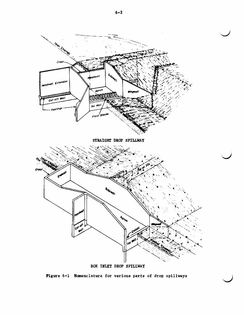
All technicians should know the various parts of a structure and their functions. Many structures are made up of four major parts - the earth embankment, spillway inlet, spillway conduit and spillway outlet. The three principal types of structural spillways used by the Soil Conser- vation Service are known as drop spillways, drop inlet spillways, and chute spillways. Nomenclature for the various parts of drop spillways are shown in Figure 6-1 and for chute spillways and drop inlet spillways in Figure 6-2.
6-2
STRAIGHT DROP SPILLWAY
BOX INLET DROP SPILLWAY
Figure 6-1 Namenclature for various parts of drop spillways

6-3
\ L CHU'JX SPILLWAY
DUG STILLING POOL
DROP INLET SPILLWAY
Figure 6-2 Nomenclature for various parts of chute and drop inlet spillways

6 -4
Various combinations of inlets, conduits, and outlets may be used. For example, a spillway for an earth dam consisting of a drop inlet, pipe conduit, and cantilever outlet is known as a pipe drop inlet spillway with a cantilever outlet, See Figure 6-3.
&
EMBANKMENT
The embankment directs the flow of water through the spillway. embankment for a drop spillway or chute generally extends from the spill- way to high ground or to a vegetative spillway. dam (farm pond) the embankment detains and impounds water as well as forces storm flows through the spillway.
The
In the case of an earth
SPILLWAY INLET
Water enters the spillway through the inlet, which may be in the form of a box, a weir in a wall, or a culvert-type entrance. straight or flared, while the wall may be straight, flared, or curved. The culvert-type entrance may be round, square, or rectangular, with a square edge, hood, or flared entrance.
The box may be
Vertical walls extending into the soil foundations under the inlet are known as cutoff walls. under the structure. prevent seepage and erosion around the ends of the structure, are called headwall extensions.
Their main purpose is to prevent water seepage Similar walls, extending laterally from the inlet to
These walls also protect against burrowing animals.
SPILLWAY CONDUIT d The conduit receives the water from the inlet and conducts it through
the structure. The conduit may be closed in the form of a box or pipe, or it may be open as in a rectangular channel. Cutoff walls or antiseep col- lars usually are constructed as a part of the conduit to prevent seepage along its length and possible failure from this source.
SPILLWAY OUTLET
The water leaves the structure through the outlet, Its function is to discharge the water into the channel below at a safe velocity. The outlet may be of the cantilever (propped) type, a plain apron outlet, or an apron with any type of energy dissipator to minimize the erosive effect of the water. Cantilever outlets are necessary in locations where the channel grade below the structure is unstable.
Vertical walls, known as toe walls, are extended below the front of the apron to prevent undercutting. Wingwall are vertical walls, extend- ing from the outlet into the channel banks, to protect against the swirling effect of the water as it leaves the structure.

6-5
L'
L
LDrop in/ef - Open fop / Box & a .......
. . . . . .
z Pbe rl . . . .
. . . . . . ............... * 1
S.Cu/verf Qype /n/ef
a 0 . . . . .
JZZ CHUTE SPILL WAY
2. Box i r - + Figure 6-3 Nomenclature for inlet, conduit
and outlet of spillway

6-6
3. STRUCTURE SELECTION
Selecting the proper structure for a given location and function is the key to successful and economical control of erosion or runoff. Each type of structure has its own range of use for a given set of conditions. Some sites will permit the use of more than one type of structure; however, there generally is one type that will provide the most economical control.
STRUCTURAL TREATMENT OF GULLIES
Treatment of gullies generally falls into two classes: control by shaping and seeding or sodding; or structural control, plus vegetation.
If slopes cannot be controlled by seeding or sodding due to an over- fall or steep portion of channel, or the width of the gully or draw into which water is being discharged is materially less than the width of waterway being treated, permanent structures will be required.
STRUCTURE SELECTION
Generally, the degree of control or protection and the size of the watershed are the primary considerations in structure selection. The structure selection diagram, Figure 6 - 4 , is useful in determining the type of structure needed.
This diagram is for average field conditions and is based on the most
d economical structure for the given head and discharge, provided the site will permit installation of the structure. Site and foundation conditions, therefore, are important factors in selecting the type of structure.
4 . STABILITY OF GRADES BELOW SPILLWAYS
The outlet of a spillway should be so designed that its function or stability will not be reduced by scour or deposition in the exit channel,
The channel grade below the spillway should be stable to prevent under- cutting of the outlet toe wall or cantilever support. Grade stability should be determined by comparing velocities for the design flow in the downstream channel with the permissible velocities for the soils and vege- tation in the channel.
The possibility of sediment deposition in the channel below the spill- way should be investigated. When sediment is a problem, the outlet of the spillway should be designed so that deposition will not interfere with the spillway discharge during the expected life of the structure.
5. STRAIGHT DROP SPILLWAY
DESCRIPTION
The straight drop spillway is a weir structure. Flow passes through the weir opening, drops to an approximately level apron or stilling basin and then passes into the downstream channel. (Figure 6-5) d

6-7
Figure 6-4 General guide t o structure se lect ion
MATERIALS
Straight drop spillways may be constructed of reinforced concrete, plain concrete, rock masonry, concrete blocks with or without reinforcing, sheet p i l ing of s t e e l , timber, and prefabricated metal.

6 -8
I
Reinforced concrete
Concrete block
Prefabricated metal
Figure 6-5 Straight drop spillways

6-9
FVNCTIONAL USE
'L 1. Grade s t a b i l i z a t i o n i n lower reaches of waterways and o u t l e t s .
2. Erosion cont ro l f o r pro tec t ion of f i e l d s , roads, bui ldings and other improvements from g u l l i e s .
3. Grade cont ro l f o r s t a b i l i z i n g channels.
4 . Out le t s fo r t i l e and sur face water a t t he upper end and along Where the channel width below the proposed drainage d i tches .
s t r u c t u r e s i t e i s l i m i t e d , the box i n l e t drop spi l lway i s more e f f e c t i v e .
5. Reservoir spil lway where t h e t o t a l drop i s r e l a t i v e l y low.
6. Control of t a i lwa te r a t the o u t l e t of a spil lway or conduit .
7. Protec t ion of the o u t l e t end of g ra s s waterways and sod chutes. Low headwall s t r u c t u r e s fo r t h i s purpose a r e sometimes r e fe r r ed t o a s a toe wall drop spil lway. See Figure 6-9.
8. Control of i r r i g a t i o n water.
ADAPTABILITY
The s t r a i g h t drop spi l lway i s an e f f i c i e n t s t r u c t u r e fo r con t ro l l i ng L r e l a t i v e l y low heads, normally up t o 10 f e e t .
ADVANTAGES
1. Very s tab le . The l ikel ihood of s e r ious s t r u c t u r a l damage i s less than fo r other types of s t ruc tu res .
2. The rec tangular weir i s less l i k e l y t o be clogged by debri.s than the openings or other s t r u c t u r e s of comparative discharge capac i t i e s .
3 . They a r e r e l a t i v e l y easy t o cons t ruc t . can be b u i l t with farm labor , while the reinforced concrete or s t e e l sheet p i l i n g type usua l ly r equ i r e s the se rv ices of a cont rac tor a
The concrete block type
LIMITATIONS
1. It i s more c o s t l y than some o ther types of s t r u c t u r e s where the required discharge capac i ty i s less than 100 c.f.s. and the t o t a l head or drop i s g rea t e r than 10 f e e t .
2. It i s not a favorable s t r u c t u r e where temporary spil lway s torage i s needed t o obta in a l a rge reduct ion i n discharge.

6-10
3 . A stable grade below the structure is essential.
SITE SELECTION
Proper site selection is dependent upon adequate field surveys and foundation data. caused by the proposed structures as they might affect adjacent highways and their drainage structures, railroads, pipelines and other improvements or properties.
Attention must be given to changed water elevations
For grade control drops with definite approach channels, the site should be selected so that the spillway can be located on a reasonably straight section of channel, with no upstream or downstream curves with- in at least 100 feet of the structure. It often will be desirable to straighten the channel alignment above and below the spillway so that it merges smoothly with the existing channel. Poor alignment may result in a reduction in discharge capacity and excessive scour of the embankment and channel banks. There should be no channel restrictions or obstacles in the approach channel that would interfere with the design flow enter- ing the spillway inlet.
The site selected should provide an adequate foundation for the spill- way. The foundation material must have the required supporting strength, resistance to sliding and piping, and be reasonably homogeneous so as to prevent uneven settlement of the structure.
d DESIGN
Planning and design of straight drop spillways normally require the assistance of an engineer. Local personnel may be trained to plan and in- stall small drop spillway structures when standard plans are available.
Measurement locations for symbols F (overfall in feet), h (depth of weir in feet), s (depth of stilling pool in feet), and L (length of weir in feet) are shown in Figure 6-6.
-t I---- L
DOWNSTREAM ELEVATION
Figure 6-6 Symbols for straight drop spillway

L
L
‘L
6-11
F = 3 ft. 700
$ ” ” .z 5do
54Cx7 8m
%
G
P 9, h zm
3 /a,
0 6 8 lo I2 I4 16 /B 20 22 24 26 28 30
Length of w e k , L, in ft.
F = 5 ff.
6 8 10 /2 /4 16 /6 20 22 24 26 28 30 Length o f weir, L . in f f .
F = 4 f t 700
$ @ o
G
b
,5 5oo
f300
4 100
3 400 Q c
91 9
200
s
0 6 8 I0 f2 /4 I6 f8 20 22 24 26 28 35
Length of weir, 1, in f t
F = 6 f f . 900
Boo
700
3 .$
6500 3 3 400
‘ 600
h
300 B
; E s 202
100
0 6 6 I0 /2 /4 16 I0 20 22 24 26 28 30
Note: h = total depth of we i r , in feet //nc/uding freeboard)
f * net drop from crest to top of transverse si/ / , in feet ( f o r type B drops keep h +f /ess ihan 0.75)
Length o f weir, L , in ff.
3.1 ~ h 3 / 2 ( 1.10 + 0.01 F)
Q = Reference- ES65 Sec.11 N.E.H.
Figure 6-7 Weir capacity for s tra ight drop spi l lways
6-12
i
5 F 3-0
6 E 2-6
5-0
13-0
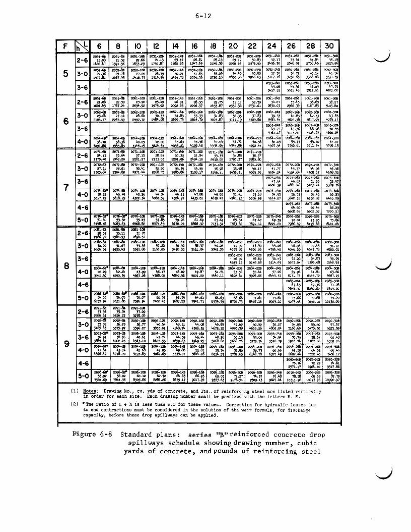
(1) Notes: Drawing No., cu. yd8 of concrete, and lbs.. of reinforcing steel are listed vertically in order for each size. Each drawing number shall be prefixed with the letters E. S.
(2) *The ratio of L + h is less than 2.0 for these values. to end contractions must be considered in the solution of the weir formula, for discharge capacity, before these drop spillways can be applied.
Correction for hydraulic losses due
d

B A R T Y P E S
A
T Y P E - I TYPE -3
E LEVATl ON
Notes: . Where required length of Mark 3 bars is not ovoiloble, two or three spliced bars may be substituted. A lop of 1 2 " i s required at each splice. The total spliced lenqth shall equal W- 6':
ALL BARS
Figure 6-9 Standard p lan for wall w i t h 2 ' -0 "
NO. 3 or 3/8" a reinforced concrete toe over fa l l drop spillway

l8'-8" 123 3.99 0.12
71 28-0
Notes:
21-4" 129 4.38 0.13
81 133-4
WIDTH OF NOTCH NO. O F BLOCKS VOL. OF CONC. C. Y. MORTAR C. Y. STEEL LBS. MASONRY W A L L REIN.
SECTION ON 5
8'-0'' lo'-# 13-4" 16'-d' 99 I 0 5 I l l 117
2.41 2.80 3.20 3.60 0.10 0.11 0.11 0.12 30 40 51 60
106-8 112-0 117-4 122-8
Q\ I + P
MASONRY W A L L REINFORCEMENT 9 Gage galvanized wire. Available in 4; 6; 8; 10" and 12" widths. Reinforcing placed between each course o f blocks af ter cores have been f iI led with concrete.
BAR-TY PES A A1
L TYPE-I
TYPE-2
2 4' - 0" I 35 4.70 0.14 9 2
138-8
First Course of Blocks to be laid 2" in freshly poured concrete slab. Cores in Blocks to be f i l led with concrete. The mortar shal l be I part port land cement to 3 par ts torpedo sand. A l l Concrete Blocks shal l be placed in a water bath a minimum of 10 minutes immediately before laying in t h e wall . A l l b lock cores shal l be ;tlhoroughly sprinkled previous to placing of the Concrete Core F i l l . Where Weir
W" exceeds 12'-0'' provide Wall Reinforcing or use Concrete Block Buttresses. Vert ical Wal l Reinforcing Steel should be added where excessive loads ore expected.
Figure 6-10 Standard plan for a concrete block toe wall drop spillway with 1'-10" overfall

6-15
Weir capac i t i e s for low-overfall s t r a i g h t drop spil lways can be de te r - mined from Figure 6-7 fo r var ious combinations of F, h , and L. Standard plans a r e ava i l ab le fo r t he Ser ies "B" re inforced concrete drop spillways. Figure 6-8 can be used for es t imat ing cos t of these s t ruc tu res . The re- quired cubic yards of concrete and pounds of re inforc ing s t e e l a r e shown for each s i ze .
L
Figure 6-9 i s an example of a standard plan fo r a re inforced concrete toe wall drop spillway. Concrete block toe wal ls a r e shown i n Figure 6-10.
The e a r t h f i l l embankment should conform t o S t a t e Standards and Specif icat ions.
6. BOX INJXT DROP SPILLWAY
DESCRIPTION
The box i n l e t drop spil lway s t ruc tu re i s a rectangular box open a t t he top and a t t he downstream end. Storm runoff , d i rec ted t o t h e box by dikes and headwalls, e n t e r s over t h e upstream end and two s ides . drops t o an apron and leaves through the open downstream end. An o u t l e t s t ruc tu re i s attached t o the downstream end of t h e box.
The flow
(Figure 6-11)
MATERIALS
Reinforced concrete i s best . However, re inforced concrete block s t ruc tu res can be used fo r low o v e r f a l l s (3 f e e t or l e s s ) and narrow channels L FUNCTIONAL USE
The box i n l e t drop spil lway can be used for the same purposes a s a s t r a i g h t drop spillway. One of i t s g r e a t e s t uses i s fo r grade and erosion cont ro l i n open drainage d i tches where the width of channel a t t h e o u t l e t i s l imited. It can serve a l s o a s a t i l e o u t l e t a t t he head of t he d i t ch . Like the drop spil lway, i t i s l i m i t e d t o ove r fa l l he ights up t o 10 fee t .
ADAPTABILITY
It i s p a r t i c u l a r l y adapted t o narrow channels where it i s necessary t o pass la rge flows of water. The long c r e s t of t he box i n l e t permits la rge flows t o pass over it with r e l a t i v e l y low heads, and t h e width of t h e spil lway need be l i t t l e , i f any, g rea t e r than t h a t of t h e ex i s t ing channel. When t h e required weir length of t he s t r u c t u r e i s over twice the bottom width of t he channel, t he box i n l e t drop spil lway should be considered. The box i n l e t drop spil lway can be combined with a bridge t o provide a road crossing, using t h e high por t ion of t he s idewalls a s abutments for the bridge. (Figure 6-12)
ADVANTAGES
Same a s fo r t he s t r a i g h t drop spi l lway, 'wi th added advantages of grea te r weir capac i ty fo r narrow o u t l e t channels.
L

6-16
Types of weirs for box i n l e t drop spillways
Figure 6-11 Box i n l e t drop spillway
Reinforced concrete

6-17
LIMITATIONS
Figure 6-12 Box-inlet drop spillway with a bridge over the top
Same as for straight drop spillways.
DESIGN
The complexity of design and layout of box inlet drop spillways re- quires the assistance of an engineer.
7. ISLAND-TYPE STRUCTURE
DESCRIPTION
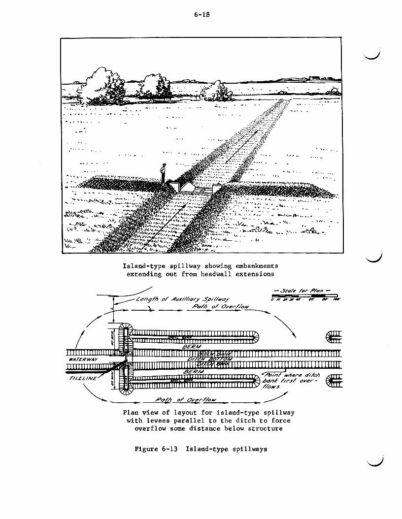
The island-type spillway uses a drop spillway in the channel with auxiliary earth spillways for carrying excess flows around the structure. Either the straight drop spillway or the box inlet drop spillway can be used. (Figure 6-13) ing each way from the structure must be provided.
To prevent washing around the structure, dikes extend- In some cases the dikes
6-18
Island-type spillway showing embankments extending out from headwall extensions
Pdh of Overf/ow ----- Plan view of layout for island-type spillway
overflow some distance below structure with levees parallel to the ditch to force Plan view of layout for island-type spillway
overflow some distance below structure with levees parallel to the ditch to force
'd
Figure 6-13 Island-type spillways
6-19
are joined to spoil banks provided there is an opening in the spoil bank downstream from the structure.
FUNCTIONAL USE
The island-type spillway is adaptable for grade control or use at the head of a channel to control the overfall. It is particularly adapted to sites where the design peak runoff is greater than the capacity of the out- let channel into which the structure is placed or empties. This structure can be used only where there is a sufficient area of nearly level land on either side of the dam that can be used as an earth spillway. Topography of the area must be such that the path of overflow around the structure will return to the channel a short distance below the structure without causing damage to the field or ditchbanks.
OPERATION OF STRUCTURE
The island-type spillway is designed so that the channel downstream from the structure will be full before the overflow around the dam reenters the channel. This reduces the possibilities of bank erosion from flow Over the bank. To accomplish this, the crest of the weir must be set below the crest of the earth spillway. must be sufficient to provide a weir notch capacity equal to the bank-full capacity of the channel at the place where the flow from the earth spill- way reenters the channel. Large flows will then pass around the earth embankment of the drop spillway, forming an island composed of the drop spillway and the headwall extension levees.
The channel above the structure at the point where overflow begins
The vertical distance between these points
L must have the same capacity as the channel below the structure. In this \may, the discharge from the channel above the structure will fill the channel below it before the banks at the structure are overtopped and flow is directed to the earth spillway. Also, the structure should be so pro- portioned that the channel banks will overflow near the structure as soon as the channel capacity flow has been reached.
ADVANTAGES
It permits the use of a drop spillway having less capacity than the peak runoff for the design storm.
LIMITATIONS
It often requires the construction of earth spillways in cropland areas. Therefore, it is harder to maintain the correct grade and elevation.
DESIGN
The layout and design of the island-type structure requires the assistance of an engineer.

6-20
8. DROP BOX (CULVERT INLET)
DESCRIPTION
A drop box i s a rectangular box i n l e t drop spillway placed a t the up- stream end of a culvert. culver t , or it can be fastened by dowel bars t o the upstream headwall of an exis t ing culvert . Storm runoff i s directed t o the box by the highway f i l l . (Figure 6-14)
It may be b u i l t as an integral par t of a new
FUNCTIONAL USE
Drop boxes a re used t o control grades above culver ts i n e i ther natu- r a l or constructed channels. They may serve as an out le t for t i l e drains. Cat t le ramps can be incorporated i n t o the design of the box when t h e cul- ver t i s used as a c a t t l e pass. See Figure 6-15 - upper sketch, The drop box i s very effect ive for erosion control i n highway ditches a s shown i n Figure 6-15 - lower sketch,
MATERIALS
Reinforced concrete i s the best and most commonly used material for
Material used should be consistent with the expected constructing drop boxes. metal can be used. remaining l i f e of the culver t t o which the drop box i s t o be attached. The addition of a headwall w i l l be required where none ex is t s .
In some cases, concrete blocks or prefabricated
ADVANTAGES
It i s one of the most economical s t ructures for control l ing overfal ls because the exis t ing culver t and highway embankment replace the out le t portion of the typical drop spillway. It has the advantage of the box i n l e t drop spillway i n tha t the w e i r length can be f i t t e d t o a narrow waterway.
LIMITATIONS
It requires the ava i l ab i l i t y of s t ruc tura l ly sound road culverts. The s t ruc ture i s often attached t o a road culver t which i s the property of a roadway governing body and, therefore requires i t s permission. may not allow maintenance and control on the par t of the landowner.
They
The design and layout of a drop box requires the assistance of an . engineer .
9. CONCRETE CHUTE SPILLWAY
DESCRIPTION
d
A chute spillway i s an open channel with a steep slope i n which flow It usually consis ts of an i n l e t , i s carried a t supercr i t ica l veloci t ies .
d

6-21
Drop box attached t o existing culvert
New culvert with a box in le t Figure 6-14 Drop box (culvert in l e t )

6-22
Drop box with c a t t l e ramp -_
OUTLET STRUCTURE FOR ROIOSIDE DITCH
IMPROVED HIGHWAY CULVERT WITH BOX INLET FOR GRADE CONTROL, SAFETY AN0 MINIMUM MAINTENAUCE COSTS
CULVERT OUTLET, FENGIN6 I.." rclII
ON OPPOSITE SIDE Of ROIOWN
Drop box for highway erosion control
Figure 6-15 Other uses for drop boxes
6-23
vertical curve section, steep-sloped channel, and outlet. The major part of the drop in water surface takes place in a channel. through the inlet and down the paved channel to the floor of the outlet. (Figure 6-16)
Flow passes
MATERIAL
Reinforced concrete is the most widely used and safest material for large chutes.
FUNCTIONAL USES
1. To control the gradient in either natural or constructed channels.
2. To serve as a spillway for flood prevention, water conservation, and sediment-collecting structures.
ADAPTABILITY
The concrete chute is particularly adapted to high overfalls where a full flow structure is required and where site conditions do not permit the use of a detention-type structure. It also may be used with detention dams, taking advantage of the temporary storage to reduce the required capacity and the cost of the chute.
ADVANTAGES
It usually is more economical than a drop inlet structure when large capacities are required. L
LIMITATIONS
There is considerable danger of undermining of the structure by ro- dents. In poorly drained locations, seepage may weaken the foundation. It must be placed on compacted fill or on undisturbed soil in an abutment.
DESIGN
The chute spillway requires the assistance of an engineer.
10. FORMLESS CONCRETE CHUTE SPILLWAY
DESCRIPTION
The formless concrete chute spillway is a spillway constructed of concrete without special forming. dimension and contour of the structure. subgrade to the depth required and troweled into shape.
The earth subgrade is excavated to the Concrete is placed against this

6-24
Longitudinal sect ion through chute
Figure 6-16 Reinforced concrete chute spillway

6-25
MATE RIALS
L Concrete with at least a 28-day strength of 2,500 lbs. per square Temperature steel is required and may be either re- inch should be used.
inforcing steel or welded wire mesh.
FUNCTIONAL USE
The formless chute may be used to: control overfalls in natural and constructed waterways; prevent erosion at the ends of terraces, outlets and waterways; and to lower runoff water Over drainage ditchbanks.
ADAPTABILITY
This type of structure is used for low heads and where low spillway capacities are required. treme variations in temperature.
It is adapted to regions that do not have ex-
ADVANTAGES
The spillway is easy to construct. Inexperienced labor can be trained to install the formless chute in a relatively short time. The elimination of wall forming produces a major saving in time and costs.
LIMITATIONS
This structure is limited to sites that have good, natural drainage. It cannot be used as a water-impounding structure nor is the life expec- tancy as long as other permanent structures. It is limited to areas where temperature variations are moderate.
DESIGN
Standard plans usually are available. Figure 6-17 is a typical plan for a small, low-head formless chute. The sidewalls and chute bottom should be no steeper than l%:l to permit placing of concrete.
CONSTRUCTION
Grading should be smooth and to line and grade, otherwise an exces- sive amount of concrete will be used to fill in rough grading and over- cutting. This type of structure should be constructed on solid ground. Seep areas should be avoided or properly drained. The soil must be damp and firm to provide a good base for the concrete. A stiff mix is needed to prevent concrete from slumping down the slope of the apron and walls. The concrete is worked into place and finished with a wood float. A steel trowel is then used for final finishing.

3 09 G Y m
H-fj "H f e e f
4' - 0' 5' - 0"
o r
Length of Cresf ( L ) lo feef z ' - o " 4 ' - # " 6 ' - O " & ' - O m
3.5 4.2 4.9 5.6
3.7 4.4 5.2 6.0
HALF ELEVATION
C C
--- HALF PLAN
"1
LONGITUDINAL SECTION ON Q
STRUCTU R A L OETAl LS
Dischorge Copocity of Spillwoy in c.fs. Lenoth of Crest (LI /)I feef 1 2 1 4 1 G I A
w i f h no freeboard 130 I 45 I 60 I 75 w i f h 6 " freedaord I /R I M I38 I48
-I+ SECTION C-C
SECTION 8-8
FW h C & / i / /
SECTION A-A
NOTES:- A.
8.
Use 5 inch thickness of concrete throughout sxcept 0s dimensioned otherwise. Reinforcing as indicated shall bu (11 3/8"( rein- forcing steel 12"c.c. both woys; or (21 No.2 gouge wel- ded wire fabric 6"c.c. both woys. lcommon des@notim 6x6921. Reinforrinp bars or mesh should be lapped one foot at 011 joints. Spillways of this type shall be constructed an solid ground. Seep areas should be ovoided or properly droined with a carefully constructed toe drainage system. This spillway shall not ;a used as a port of o woter impounding structure. The disturbed area odjocent to the spillway shot1 be bochfilfed,campocted and sodded. The length lL1 of the spillwoy sholl be limited by the amount of concrete that can be adequotely mixed, placed and finished in one day) time with the labor and equipment available or a Mux. L&o* The maximum *n"for this spillway is 5'0"
C.
D.
E.
F.
6.

6-27
L
Q)
dl
#.
f 8 0P
8
Figure 6-17
Typical standard p
lan for low
head
formless con
crete chu
te

6-28
11. SOD CEUTE SPILLWAY
DESCRIPTION
The sod chute i s a steep, sodded section of a watercourse constructed t o conduct the design flow through it a t a safe velocity. When water i n a watercourse flows through a chute with a steeper grade, a change i n flow takes place. increase i n velocity. widths due t o the increased velocity. tween the waterway and the chute is necessary t o bring about an orderly change i n velocity and channel widths.
(Figure 6-18)
A decrease i n depth of flow occurs with an Chute widths usually w i l l be less than watercourse
Therefore, a t rans i t ion section be-
See Figure 6-19.
Figure 6-18 Sod chute with toe-wall drop spillway
MATERIALS
Required vegetation may be established by transplanting sod or , i f the water can be diverted around the section for a suf f ic ien t t i m e , it may be established by seeding.

6-29
Figure 6-19 lOanenclature fa r rod chute des ign
1. To control overfallr or abrupt chaa&w in the elope of a natural or conrtructad wrtara~y.
2. A t the lower end of a conrtructed Chatme1, t o conduct water over an overfall i n to a natural charnel.
3. To conduct water from an adjacent f l a t area t o the bottom of a ditch.
ADAPTABILITY
The sod chute i r adapted t o small waterrhede and s i t e s where good, dense sod can be developed and maintained. chute must be rtable. dit ions a t the lower end of the chute bay not be favorable t o establish and maintain vegetation, a toe w a l l drop rpilltnay should be used. favorable condition8 include poor soil , rocky or wet conditions, or s i l t a - t ion fran adjacent ditches or s t reae. the end of the sod chute above there unfavorable conditions and permits the maintenance of a good rod.
The watercourse below the When the channel be lm the chute is narrow, or con-
Un-
The tao w a l l drop spillway raises
Refer t o section on Straight Drop Spillways.
Low material C O r t 8 , and may be constructed with farm labor,

6-30
LIMITATIONS
The sod chute is limited to sites with good soil and where the veloc- ity of flow in the chute is low enough to maintain the sod cover. This generally means small watersheds and low overfalls where there is no long, sustained flow. This type of structure is not adapted to areas where nor- mal rainfall is inadequate for growing a good protective cover. care must be taken in the design, layout, construction, and maintenance.
Particular
Design nomenclature is shown in Figure 6-19. Basically, the sod chute is designed the same as a vegetated waterway. are generally constructed by transplanting sod or protected by a diversion until seeding is established, the range of permissible velocities is higher than for watercourses where vegetation is established from seed without diverting the flow. Velocities of 6 feet per second are normally used when good quality sod is used or where water is diverted and a good vegeta- tion can be established. Velocities of 7 to 8 feet per second should be used only on established sod of excellent quality on cohesive soil and where provisions are made for special maintenance.
However, since sod chutes
The bottom slope of the sod chutes should not be steeper than 6 : l ; flatter slopes are better. The chute should be designed with a flat bottom.
Chute widths usually will be less than the watercourse width, with a tendency toward restriction of flow at the entrance. To overcome this, a transition section between the waterway and the entrance to the chute should be planned so that the width of the watercourse is gradually reduced to the required width of the chute. definite depth of flow at the entrance of the chute in order to assure ade- quate entrance capacity. quired depth. entrance depth for the various bottom widths and depths of flow in the chute.
d It is also necessary to provide for a
Sometimes dikes are required to provide the re- The sod chute design chart, Figure 6-20, gives the required
When adverse conditions mentioned under "Adaptability" are encountered, a toe wall drop inlet structure should be planned. Refer to the section on Straight Drop Spillways. Note toe wall structure in Figures 6-18 and 6-19.
These points should be followed to assure a properly constructed sod chute:
1. Do not build on fill material.
2. Fine grade by hand if necessary to assure a uniform flat bottom from side to side and leave surface in a condition similar to a seedbed.

SOD CHUTE - DIMENSION TABLE TRAPEZOIDAL CROSS SECTION
PERMlSSl6LE JELOCITY: FT./SEC. 4 516 718 4 516 718 4 5161718 4 516 718 4 516 718 4 516 718
FAIR GOOO EXCELLENT FAIR GOOD EXCELLENT FAIR GOOD jExcELLEnT FAIR MOO EXCELLENT FAIR GOOO EXCELLENT FAIR 0000 EXCELLEN1 CONDITION OF +nn S
I .3 0.7
- -
-
4711 I I r I 11 I I I I I I I I I I It I 1 I I
6-3 2
3.
4.
Cut sod thin. Lay sod i n s t r i p s across the chute. S ta r t laying sod a t the bottom. Stagger jo in t s of the sod st r ipe. Lay sod two feet up s i d e elopes. F i l l any open jo in t s with loose so i l . Tamp or r o l l a l l l a id sod. Sod should be pinned down i n same manner. Wire (No. 9) s taples ,
or chicken wire pegged down, are sane successful methodr used.
Protect from livestock during cr i t ical eeasons. Xowing or controlled grazing is a necessity for maintenance.
12. DROP IRLET SPILLWAYS
DESCRIPTION
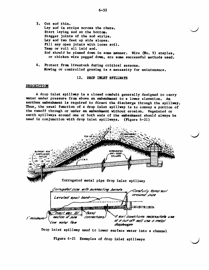
A drop i n l e t spillway i s a closed conduit generally designed t o carry water under pressure from above an embankment t o a lower elevation. earthen embankment i s required t o direct the discharge through the spillway. Thus, the usual function of a drop i n l e t spillway i s t o convey a portion of the runoff through or under an embankment without erosion. ear th spillways around me or both ends of the embankment should always be used i n conjunction with drop i n l e t spillways.
An
Vegetated or
(Figure 6-21)
wy Corrugated metal pipe drop i n l e t spillway
mC83s/ib/b UJQ d& cu/-afjf my UjiG D mfu/ d&p&p7
Drop i n l e t spillway used t o lower eurface water in to a channel
Figure 6-21 Examples of drop i n l e t spillways

6-33
MATERIALS
‘L The riser of a drop i n l e t spillway may be of plain concrete, reinforced concrete, concrete blocks, or pipe. c r e t e , concrete or clay t i l e , or corrugated or smooth metal pipe having watertight joints .
The barrel may be of reinforced con-
FUNCTIONAL USES
1. Principal spillways for farm ponds or reservoirs.
2. Grade s tabi l izat ion.
3. A t lower end of water disposal system.
4. Principal spillways for debris basins.
5 . Roadway structures.
6 . Flood prevention structures.
7.
ADAPTABILITY
Surface water i n l e t for drainage or i r r iga t ion .
It i s a very e f f i c i en t s t ructure for controll ing r e l a t ive ly high gul ly heads, usually abuve 10 feet . appreciable amount of temporary storage above the in le t . used i n connection with re la t ive ly low heads, as i n the case of a drop in- le t on a road culver t , or i n passing surface water through a spoi l bank
It i s w e l l adapted t o sites providing an It may a l so be
L along a drainage ditch.
ADVANTAGES
For high heads, it requires less material than a drop spillway. an appreciable amount of temporary storage is available, the capacity of the spillway can be materially reduced. B e s i d e s effect ing a reduction i n cos t , t h i s reduction of discharge r e su l t s i n a lower peak channel flow be- low, and can be a favorable factor i n downstream channel grade s tab i l iza- t i on and flood prevention.
Where
LIMITATIONS
Small drop i n l e t s a re subject t o stoppage by debris. It i s l i m i t e d t o locations where sat isfactory ear th embankments can be constructed.
L
CLASSIFICATION
Drop i n l e t spillways a re c lass i f ied according t o material i n t o two general types : monolithic box-type of reinforced concrete.
FIPE DROP-T DESIGN
pipe drop i n l e t s constructed of sane type of pipe; and the
Pipe drop i n l e t s usually are confined t o smaller jobs where:
1. The value of the improvement may not j u s t i f y the use and cost of monolithic reinforced concrete.

6-34
2. Where considerable storage i s available i n proportion t o the s i z e of the watershed.
3 . Where the useful l i f e of the project is limited.
Large s ize pipe drop i n l e t s require the services of an engineer. The smaller s izes generally used i n farm ponds can often be designed by the Work Unit s t a f f when standard plans are available.
When corrugated or he l i ca l metal pipe is planned, only the heavier weight should be used, following the more conservative recoxmuendations of culvert pipe manufacturers. A coating of bituminous material w i l l extend the e f fec t ive l i f e of t h i s type of pipe. with watertight metal bands caulked or otherwise sealed against leakage, and antiseep co l la rs used t o prevent seepage along the pipe. Sheet metal antiseep co l la rs , or diaphragms, furnished by culvert pipe manufacturers, have a watertight connection t o the outside of the pipe. co l l a r is superior t o concrete co l l a r s for metal pipe because d is tor t ion of the pipe from loading may crack the concrete collar o r rupture the pipe; whereas a metal antiseep co l l a r w i l l adjust and remain in tac t .
A l l j o in t s should be provided
This type of
Typical appurtenances for corrugated metal (C.M.) pipe drop i n l e t s are shown i n Figure 6-22 - sheets 1, 2 and 3. When pipe drop i n l e t s are used as spillways for storage reservoirs where the water must be released doom- stream, such as i r r iga t ion reservoirs, some type of release f a c i l i t y m e t be provided. Figure 6-23, sheets 1 and 2, shows typical d e t a i l s fo r re- lease by an inclined gate structure.
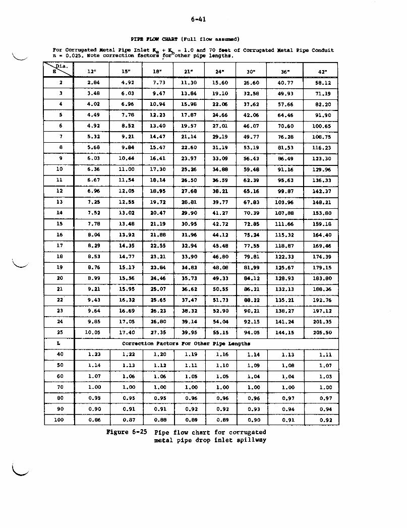
d Figure 6-24 can be used t o determine capacity of 8- and 12-inch C.M.
pipe drop in l e t s , as w e l l as the height of riser required t o provide the capacit ies shown. Pipe capaci t ies for larger corrugated metal pipe are given i n Figure 6-25 and fo r concrete pipe i n Figure 6-26 based on required i n l e t conditions for pipe flow. The required i n l e t condition can be deter- mined from Figure 6-27.
Reinforced concrete culver t pipe or water pipe w i l l make a more sa t i s fac tory pipe drop i n l e t than corrugated metal, par t icu lar ly fo r em bankment heights greater than 20 fee t , or where long service l i f e is desired. Concrete pipe must be properly cradled and bedded. A l l j o in t s must be watertight.
The design of a drop i n l e t spillway cannot be made independently of the design of the ear th embankment, emergency spillway, and other elements of the t o t a l s t ructure .
The design should provide for suf f ic ien t temporary storage between the c re s t of the i n l e t and the emergency spillway t o permit a drop i n l e t spillway of reasonable s i ze and cost . depends largely on the amount of t h i s temporary storage. Tailwater w i l l influence the layout of the spillway out le t and the amount of hydraulic head available t o produce discharge through the spillway. Therefore, it must be determined accurately for each location.
The s i ze of the drop i n l e t spillway

6-35
1
tor rrction
CORRUGATED METAL PIPE RISER WITH CONICAL TRASH RACK AND BAFFLE
.. * . c '< - -4 r, 4 . c. ' k h
TIMBER SUPPORT
-. - /
REINFORCED CONCRETE SUPPORT
TYPE OF SUPPORT FOR CANTILEVER OUTLETS
locknut onc on each
- steel rod8
= 2"x 12" plank
4 H X 4 w POIt
I" dla. plpe
~ c . u . pipe riser
TIMBER HEADWALL AND TRASH RACK
~ ~~
Figure 6-22 Appurtenance for metal pipe drop inlets
(sheet 1 of 3)

6-36
ELEVATION Of WASSENBLED M*pWR*oy
DETAILS OF CORRUGATED METAL DIAPHRAGM
br
DETAILS OF HELICAL PIPE DIAPHRAGM
Figure 6-22 Appurtenances for metal pipe drop inlets
d (sheet 2 of 3)

6-37
L
L
DETAILS OF WATERTIGHT COUPLING BAND FOR C.M. PIPE
I DCTAIL ff ROO AN0 LUB
ALTERNATE 'L' LW
ELEVATION
RUBBER GASKET CROW SECTION DETAIU Of SLEEVE XlNT COR WJCAL PWT
DETAILS OF WATERTIGHT COUPLING BANDS FOR HELICAL METAL PIPE
Pigme 6-22 Appurteorrncer far metal pipe drop inlets (rheet 3 of 3) L

6-38
f @f pp sum&
SECTIONAL ELEVATION OF DAM ALONG CENTERLINE OF PRINCIPAL SPILLWAY
I 4 PLAN
DETAILS OF GATE HOIST
END ELEVATION
Figure 6-23 Typical appurtenances for pipe spillways with Inclined gate release structure
(sheet 1 of 2)

6-39
DETAILS OF GATE STEM
c
L
L
PLAN BHOWlNe TRASH RACK)
mcrlorbont whik p4v,io *k concrete.
SECTIONAL ELEVATION A - A
DETAILS OF INLET STRUCTURE

6-40
a7 1.1 9.5 - -_ I 1.1 9.7
n 1.4 9.s
I0 1.4 10.1
1 1
I I
Figure 6-24 Capacity chart for 8'' and 12" C,W, pipe drop inlet rpillww
6-41
7
8 1
PIPE PLUV CBART (Full flaw assumed)
For Corrugated Netal Pipe I n l e t Ke + ]5 I 1 .0 and 70 feet of Corrugated Xetal Pipe Conduit n = 0.025. Note correction factors for other pipe lengths.
5.32 9.21 14.47 21.14 29.19 49.77 76.28 108.75
5.68 9.84 15.41 22.60 31.19 53.19 81.53 116.23
L
9 6.03
10 I 6.36
4 4.02 6.96 10.94 15.98 22.06 31.62 57.66 82.20
5 4.49 7.78 12.23 17.87 24.66 42.06 64.46 91.90
6 1 4.92 8.52 13.40 19.57 27.01 46.07 70.60 100.65 -
10.44 16.41 23.91 33.09 56.43 86.49 123.30
11.00 17.30 25.26 34.88 59.48 91.16 129.96
14- 6.67 11.54 18.14 26.50 36.59 62.39 95.63 136.33
6.96 12-05 18.95 27.68 38.21 65.16 99.87 142.31
1 3
14
15
7.25 12.55 19.72 28.81 39.71 67.83 103.96 148.21
7.52 13.02 20.47 29.90 41.21 70.39 107.88 153.80
7.78 13.48 21.19 30.95 42.72 72.85 111.66 159.18
16
17
8.04 13.92 21.88 31.96 44.12 15.24 115.32 164.40
8.29 14.35 22.55 32.94 45.48 17.55 118.87 169.46
1 20 I 8.99 15.56 I 24.46 I 35.73 I 49.33 I 84.12 I 128.93 I 183.80 I L
18 8.53 14.11 23.21 33.90 46.80 79.81 122.33 174.39
19 8.76 15" l ? 23.84 34.83 48.08 81.99 125.67 179.15
I 23 I 9.64 I 16.69 I 26.23 I 38.32 I 52.90 I 90.21 I 138.27 I 197.12 I
15.95
16.32
25.07 36.62 50.55 86.21 132.13 188.36
192.76 25.65 37.47 51.13 88.22 135.21
24
25
Figure 6-25 Pipe flow chart for corrugated metal pipe drop i n l e t spillway
9.85 11.05 26.80 39.14 54.04 92.15 141.24 201.35
10.05 17.40 27.35 39.95 55.15 94.05 144.15 205.50
L
40
Correction Factors For Other Pipe Lengths
1.23 I 1.22 1 1.20 I 1.19 I 1.16 1 1.14 1 1.13 I 1.11

6-42
12'
2 4 .54
15" 18' 21" 24" 30" 36" 42"
8.01 11.74 16.60 22.44 36.74 54.65 76.02
3
4
5 I 1
- ~
- T p p ~
5.56 9.81 14.39 20.33 27.49 45.00 66.94 93.11
6.42 11.33 16.61 23.48 31.74 51.96 77.30 107.52
7 . 1 8 12.66 18.57 26.25 35.49 58.09 86.42 120.21
I 6 11 7.87 I 13.86 I 20.34 1 28.75 1 38.87 I 63.63 1 94.65 I 131.66 1
9
10
11
1 1
9.64 17.00 24.92 35.22 47 -61 77.94 115.95 161.28
10.16 17.91 26.26 37.12 50.18 82.15 122.21 169.99
178.32 10.65 18.78 27.55 38.94 52.64 86.18 128.20
I 7 11 8.50 I 14.98 I 21.98 I 31.06 I 41.99 I 68.74 I 102.27 I 142.25 I
12
13
14
15
I 8 T 9.08 1 16.01- 1 2 3 . 4 9 T 3 3 . 2 O P 1 8 8 7 7 3 . 4 7 T l 0 9 . 3 0 1 1 5 2 . 0 3 1
11.13 19.62 28.77 40.67 54.97 89.99 133.88 186.22
11.58 20.42 29.95 42.33 57.23 93.68 139.37 193.86
12.01 21.10 31.07 43.93 59.37 97.19 144.59 201.12
12.44 21.93 32.17 45.47 61.46 100.62 149.69 208.21
16
17
18
19
20
12.85 22.65 33.22 46.96 63.48 103.92 154.60 215.04
13.24 23.35 34.24 48.40 65.43 107.12 159.35 221.65
13.63 24.03 35.24 49.81 67.34 110.23 163.99 228.10
14.00 24.68 36.21 51.17 69.18 113.25 168.48 234.34
14.36 25.32 37.14 52.50 70.97 116.18 172.84 240.41
21
22
23
24
25
14.72 25.95 38.07 53.80 72.73 119.07 177.13
15.06 26.56 38.96 55.06 74.43 121.85 181.27
15.40 27.16 39.84 56.31 76.11 124.60 185.36
15.73 27.74 40.69 57.51 77.75 127.28 189.35
16.06 28.32 41.53 58.70 79.35 129.90 193.25
I 246.38
252.13
257.83
263.37
268.80
40
50
60
I L 0 Correction Factors For O t h e r Pipe Length6 1 1.15 1.13 1.11 1.09 1.08 1.06 1.06 1.05
1.09 1.08 1.07 1.06 1.05 1.04 1.04 1.03
1.04 1.04 1.04 1.03 1.03 1.02 1.02 1.02
-- __ ~~~
90 0.93 0.94
100 0.90 0.91
I 80 I 0.96 1 0.96 I 0.97 1 0.97 I 0.98 I 0.98 I 0.98 I 0.99 I ~ ~~ ~ - -
0.94 0.95 0.95 0.96 0.97 0.97
0.92 0.93 0.93 0.95 0.95 0.96

6-43
- Weir Control a t Entrance
Orifice Control a t Entrance of Corviuit
Orifice Control a t Entrance of Barrel or Short Tthe
Control
- Full Pipe Flou
Figure 6-27 Chart for determining inlet proportions and required head over inlet
Sheet 1 of 3

6-43a
Head in Feet Riser D meter L
inches 1.7 1.8 1.9 I 2.0 1 2.1 I 2.2 I 2.3 I 2.4 I 2.5
&2 66.5 72.5 OFUFICE FLm
L8 76.0 82.8 89.7 96.9 104.1 CONDITIONS C0"FOL
54 85.5 93.2 100.9 109.0 117.1 125.6 134.5 l43.3
60 95.0 103.6 112.1 121.1 130.1 139.5 149.3 159.2 169.0 J b
I I I I I 5.d 7.51 9.6112.6 I
30
36 6.4 9.0 11.8 15.1
LER ROP 3 Rxri
ead 0.8
- - - - 9.3
10.7
12.3
WlTSs (1) The discharge capacities shown i n t h i s table are based on the
$I2 fornula: 02 C2 L 2
02 = discharge capclcity of weir, i n c.f.8. C2 0 weir coefficient 3.33 L - length of weir crest, i n feet (for circular r iser with
headwall, L = 2.57 times diameter of riser). H2 - distance from crest of riser t o water surface in
reservoir, i n feet. (2) Thr, diameter of the riser should be a t least 4 times the
diameter of barrel. (3) U8e th i s table i n conjunekion w i t h orifice fluu arrd full pipe
flaw conditions t o determine capacity of the drop inlet. j Figure 6-27 Chart f o r determining i n l e t p ropor t ions
and required head over i n l e t
Sheet 2 of 3

c
Figure 6-27 Chart for determining i n l e t proportions and required head over i n l e t
Sheet 3 of 3

6-44
In many instances, par t icular ly with small pipe drop i n l e t s , the con- dui t is placed a t an angle with the dam t o obtain be t te r downstream align- ment, t o provide a location on undisturbed ground, or t o reduce the height of the riser. of conduits placed a t an angle.
Figure 6-28 gives a procedure for determining the length
Stop I. From field swvr) dotormino L, In feet ond Angk "A" In dagroes. 2. Enter Toblr I with with L, ond Angk "A" to fid 4, tho incroon in Imgth dur to tho s lur OlQlO.
4. dot or mi^ 'ha, tho total toll in tho pipe fin foot). 5. Enter Toblr H with L, and h to find L,. tho incraow In Iongth dw to slope. 6. L, + L4 *Ls , which i s tho nquirod lmgth of pipo In fool. Roved off to #t high own robe.
5 L, Lx 8 foot * L,
UMPLE P u
J ----
Figure 6-28 Procedure for determining length of conduit
(rheet 1 of 2) 3

c-
3.9 3.7 3 . 5 3 .4 3.3 3.1
::: 2.8 2.7
2 .5 2.4
2.6
2.3 2 . 3
2.2 2.1 2 . 1 2 . 0
::; 1.9 1.8 1.8 1.7
1.7 1 . 7 1 .6 1 .6 1.6 1.5 1.5
1 . 5 1 .5 1 . 4 1.4 1.4 1 . 4 1 .3 1.3 1 .3 1.3
1 .3 1.2
::: 1.2 1.2
1 . 1 1.1 1.1 1 .1 1.1
U - L e
c
4.' 4.! 4.: 4.: 4.1 3.S
; : f
3.! 3.4
3.1 3.c
. . 3.2
2.g
. . 2.E 2 . 7 1 . 6 2.5 2.5
::: 2.3 2.2
2.1
2.1 1.1 2.0 2.0 1 .9 1 . 9 1.9
2.2
1.8 l . Q 1 . 8 1 .7 1.7 1 . 7 1 .7 1 .6 1.6 1 .6
1.5 1.6
::: 1.5 1.4
1 . 4 1.4 1.4 1 .3 1 . 3
i
TABLE I: VALUES OF L t (INCREASE IN LENGTH DUE TO SKEW)
I Value Of L, - F e e t I
5 0
1 2 . 2 1 2 . 8 1 3 . 4 14.0 14 .7 1 5 . 3 -rKT 16 .5 1 7 . 1 17 .7 18 .3 7x3- 1 9 . 5 20.2 20 .8 21.4
7E-r 22.6 23 .2 23 .8 24.4
-xa- 25.7 26 .3 26.9 27.5 28 .1 28.7 7.9.3 29.9
-
* * 4%-
31 .8 32 .4 33 .0
34 .8 35.4 36.0
31.9
Angle "A" - D.( 65
4.1 4 .3 4 . 5 4 .8 5 . 0 5 . 2 T
5 . 6 5 . 8 6 . 0 6 . 2 m 6 . 6 6 . 8 7 . 0
-
-k& 7 . 7 7 . 9 8.1 8 . 3
-K!r 8 . 7 8 .9
9 . 7 9.9
10.1 10 .3 Tmr 10.8 11.0 1 1 . 2 * 11.8 1 2 . 0 1 2 . 2 12 .4
1 2 . 8 Tm-
I.. - 70
2 . 6 2 . 7 2 . 8 3 . 0 3.1 3 .2 -Kr 3.5 3 .6 3.7 3 .9 33- 4.1 4 . 2 4.4 4 . 5 4 . 6 4.8 4 . 9 5 . 0
-
++- 5.4 5 . 5 5 . 6 5 . 8 5 .9 6 . 0 6 . 2 6 . 3
-
$3-
* 6 . 7 6 . 8 6 . 9
7.3 7 . 4 7 . 6 7 . 7 73- 7 . 0 -
75
1 .4 1 . 5 1.6 1 . 6 1 . 7 1.8 33- 1.9 2 . 0 2 . 0 2 . 1
-272- 2 . 3 2 . 3 2 . 4
-
* 2 . 6 2 .7 2.8 2 . 8
-27 r 3.0 3 . 0 3 . 1
-%- 3 . 3 3 .4 3 . 5 3 . 5 XT 3.7 3 . 7 3 . 8 * 4.0 4.1 4 . 2 4 . 2
X - T 4.4 -
0 . 6 0 . 2
0 .7 0 . 2
0.8 0 .2
0 : s 0:2
0 .9 0 . 2
1 . 0 0 . 2 1 . 0 0 .3 1.0 0 . 3 1.1 0.3
0 . 3
1.4
1 6 0 4 1:s I 014 1 1 . 7 0.4 w 1.8 0.4
i cscr) -11
2, 1 -% e4
68 + -%-
--%
* 4%-
%-
* *
74 76 78
a4 06 60
94 % 98
101 106 108
114 116 118
124 126 128
134 1% 138
144 146 148 150 -
TABLE HI VALUES Of L4 (INCREASE IN LENGTH DUE TO SLOPE)
- 4
0.1
0.1 0.1 0.2
- 0.2
4x
44
0.1 0.1 0.1
0.1 0.1 0.1 0.1 T I 0 . 1 0.1 0.1
%
%
E
E
6
H
H
0.1 0.1 0.1
0.1 0.1 0.1
0.1 0.1 0.1
0.1 0.1 0.1
0.1 0 . 1 0 . 1
0.1 0.1 0 . 1
0.1 0.1 0.1
- 6
0.5 0.4 0.4 0.4 0.4
-
++ i%
%
&+
E
E
24-
%-
%-
0 .3 0.3 0.3
0 . 3 0.3 0 .3
0 .2 0.1 0.2
0.2 0.2 0.2
0 .2 0 .2 0 .2
0.2 0 .2 0.2
0.2 0.2 0.2
D . l D . 1 D . l
D . 1 3 . 1 g 1 . 1 I. 1 1 . 1 ).1
- 8
0.1 0.1 0.' 0.' 0.' O.( m 0.1 0.t O.! O.! -67 O.! O.! 0.5 0.1 -03 0.4 0.4 0.4
-
%
%
fi4
fi4
s is e
0.4 0 .4 0.4
0 . 3 0 . 3 0 . 3
0 . 3 0 . 3 0 . 3
0 . 3 0 . 3 0 .3
0 .3 0 . 3 0 . 2
0 .2 0 .2 0 .2
0.2 0.2 0 . 2 o.?
- 10
1.1 1.1 1 . 1 1.1
-
1 . 0 w 0 .9 0.9 0 .9 0.8 53 0.8 0.8 0 .7 0.7 0-3 0 .7 0 .7 0 .6
E
E
8
E
?+
e
0.6 0.6 0.6
0.5 0.5 0.5
J.5 3.5 3.5
>.I >.I 1.4
1.4 ).I 1.4
1.4 t.4 1.4
j.4 1.3 ) . 3 1.3
w
h
- Of -
met - 16
3 .1 2 .9 2.8 2.7 2.6
-
%
44
+4
4 5
2 .3 2 . 2 2 . 2
2 . 0 1 . 9 1.9
1 .7 1 .7 1 .6
1 .5 1 . 5 1.4 u 1.4 1.4 1 . 3 1 . 3
H 1 .2 1 .2 f i 1 . 1 1 .1 1.1
6
E
H
1.0 1.0 1 . 0
1 . 0 0 . 9 0.9
0 . 9 0.9 0.9 0.p
18 I 20
Mlputed f x a the relatianmhip 4- m L + h - L
I. In most coser the voluer in the tobles ore M m r l y the soma thot interpolation i8 not necer8ory. This mu8t be decided occording
2. When the80 tobles ore used with drop inlet spillwoys, the volues of h i s not the tolo1 toll. but only the fo l l occurring to the degree of occurocy required.
within the pipe.
7
26 -
3x- 5 .9 5 .7 5 .6
-2%
44-
* -H
++ 4%.
43-
5 . 1 4 . 9 4 .8
4 .4 4 . 3 4 . 2
3.9 3 .8 3 .8
3 .5 3.5 3.4
3 . 2 3 . 1 3 .1
2.9 2.9 2 .8
2.7 2.7 g 2.5 2.5 2.4
%- 2 . 3 2 .3 2.3 2 . 1 -

6-46
The outlet of the d r o p i n l e t spillway should be i n l ine with the down- stream channel. the conduit i s s t ra ight and a t a 90-degree angle with the centerline of the embankment.
The layout providing the shortest conduit w i l l ex is t when & MONOLITHIC BOP[-TYPE DROP INLET DESfCaS
This type must be designed by an engineer. Reinforced concrete has been used most extensively for locations requiring a 3' x 3' culvert or larger. Removal of forms i s d i f f i cu l t on smaller culverts. The rein- forced concrete monolithic drop in l e t i s generally recamrended for the larger and more important spillways. See Figure 6-29.
Figure 6-29 Reinforced concrete monolithic drop in l e t spillway
13. WXXl INLET SPILLWAY
DESCRIPTION
The hood in l e t rpfllway consists of a pipe conduit with the in l e t end formed by cutting the pipe a t an angle. on top and f igura t ivdy forms a hood over the entrance. An anti-vortex wall or plate i s located on the upper side of the pipe a t the inlet . (Figure 6-30)
The long side of the cut is placed

6 -47
Metal p i p e with hood i n l e t L
Protective Post
Corefully tomp soil oround pipe before bock fillin9
i 20'Section of pipe
L
Hood i n l e t used t o lower surface water into a channel
Figure 6-30 Hood i n l e t spillways

6 -48
MATERIALS
The hood inlet spillway can be built of corrugated metal, welded d steel, concrete, asbestos cement, and possibly other types of pipe. Corru- gated metal is the most camonly used pipe, especially on small structures.
FUNCTIONAL USE
Same as for pipe drop inlets.
ADAPTABILITY
It is best adapted for use at those sites where the pipe can be in- stalled in the original ground. is placed in the embankment.
Construction is complicated when the pipe
ADVANTAGES
The hood inlet spillway will flow completely full regardless of the slope of the conduit if the length of the hood is properly selected and the head on the inlet is adequate. As compared with the drop inlet, it has the advantage that no riser is required and there is less fill over the pipe. It is simple to fabricate and install and is comparatively low in cost.
For the same crest elevation, hooded pipes over 24 inches in diameter d require a greater depth of water over the inlet to obtain full pipe flow
than a pipe drop inlet. Both of these may be overcome with a box and hood combination similar to the one shown in Figure 6-31.
Icing presents a problem in some areas.
Splitter Type Anti- Vortex W a l l -f$$n let Con du I t
R/C Box
Figure 6-31 Box and hood inlet combination
The hydraulic design of a hood inlet spillway is based on the addi- tion of a hood and anti-vortex device to the inlet of a culvert on a steep slope. These additions will make the culvert flow full when the water sur- face above the inlet (invert of the pipe) reaches about 1.8 times the diam- eter of the pipe. pipe, comnonly used for farm ponds, can be found in Figure 6-32.
A capacity chart for 8- and 12-inch corrugated metal

6-49
- a 0 c
CROSS SECTION OF DAM ON f- OF PIPE SPILLWAY
CAPACITY TABLE OF HOODED INLET IN C . F . S . FOR VARYING HEADS I
Figure 6-32 Capacity chart for 8- and 12-inch C.M. pipe hood i n l e t spillway
Figure 6-33 provides capacit ies for larger corrugated metal pipe hood in le t s . Capacities for smooth pipe can be found i n Figure 6-34.
The use of some type of device t o prevent vortex formation i s neces- sary for developing maximum capacity shown i n the previously mentioned figures. device similar t o the one shown i n Figure 6-35 can be used.
When the hood i n l e t i s of corrugated metal p i p e an anti-vortex

PIPE FUlW CHART ( F u l l f low assumed)
For Hooded I n l e t Ke = 1.08 and 70 f e e t of Corrugated Metal Pipe Conduit , n = 0.025. Note c o r r e c t i o n s for o t h e r pipe l engths .
5
6
7
8
L I I I i
4.40 7.74 12.21 17.64 24.48 41.72 63.70 90.80
4.82 8.47 13.37 19.32 26.82 45.70 69.77 99.45
5.21 9.16 14.45 20.88 28.97 49.37 75.38 107.45
5.57 9.78 15.44 22.31 30.97 52.77 80.57 114.85
10.94
11.48
I II I I I I I I 1 -I
17.26 24.95 34.62 59.00 90.09 128.41
18.11 26.17 36.32 61.90 94.50 134.70
I 9 11 5.91 I 10.38 I 16.38 I 23.61 I 32.85 I 55.98 I 85.47 1 121.83 I
12
1 3
14
15
16
c I I I I I I I 1
6 .'82 11.99 18.91 27.33 37.93 64.64 98.69 140.67
7.10 12.48 19.69 28.45 39.49 67.29 102.73 146.44
7.37 12.95 20.43 29.52 40.97 69.83 106.61 151.96
7.63 13.40 21.15 30.56 42.41 72.27 110.34 157.28
7.88 13.84 21.84 31.56 43.80 74.64 113.96 162.44
1 7 8.12 14.27 22.51 32.53 45.15 76.94 117.46 167.44
18 8.36 14.68 23.17 33.48 46.46 79.17 120.88 172.31
19 8.59 15.08 23.80 34.39 47.73 81.34 124.19 177.02
20 8.81 15.47 24.42 35.28 48.97 83.45 127.41 181.61
-
2 1
22
9.03 15.86 25.02 36.16 50.18 85.52 130.57 186.12
9.24 16.23 25.61 37.00 51.36 87.52 133.62 190.46
24
25
I 23 (1 9.45 I 16.59 I 26.19 I 37.84 I 52.52 I 89.49 I 136.64 I 194.77 1 9.65 16.95 26.69 38.65 53.64 91.42 139.57 198.95
9.85 17.30 27.30 39.45 54.75 93.30 142.45 203.05
L
40
Correc t ion F a c t o r s For O t h e r Lengths
1.23 I 1.21 I 1.19 I 1.18 I 1.16 I 1.13 I 1.12 I 1.10
80 11 0.95 I 0.95 0.95
0.91
0.88
0.96 0.96 0.96 0.97 0.97
0.92 0.92 0.93 0.94 0.94
0.89 0.89 0.90 0.91 0.92
Figure 6-33 P i p e flow chart for Corrugated metal pipe hood inlet spillway

6-51 PIPE FUII( CHART (Pull flow aoo\lod)
8 6.40 9.69 13.69 15.99 23.84 33.29
9 6.79 10.28 14.52 16.96 25.29 35.31
10 7.16 10.84 15.31 17.87 26.65 37.22
11 7.51 11.36 16.05 18.74 17 -95 39.03
-
I 12 I , 7.83 I 11.87 I 16.77 . 19.58 . 29.20 . 40.77 I
For Hooded I n l e t l(e = 1.08 and 70 feet of antooth pipe conduit, n = 0.010. Note corrections for other lengths.
14
15
16
17
18
6 T 5.54 - r 8.39 11.86 1 13.84 I 20.64 I 28.83 I
8.47 12.82 18.11 21.15 31.54 44.05
8.77 13.27 18.75 21.89 32.64 45.59
9.06 13.71 19-36 22.61 33.72 47.08
9.33 14.13 19.96 23.31 34.75 48.53
9 -61 14.54 20.54 23.99 35.76 49.94
19
20
21
22
23
24
25
L
I 13 11 8.16 I 12.36 I 17.46 1 20.41 I 30.39 I 42.45
9.87 14.94 21.10 24.64 36.74 51.31
10.12 15.33 21.65 25.28 37.69 52.64
10.38 15.71 22.19 25.91 38.63 53.95
10.62 16.07 22.70 26.51 39.53 55.21
10.86 16.44 23.24 27.11 40.42 56.45
11.09 16.79 23.72 27.69 41.29 57 -67
11.32 17.14 24.21 28.26 41.14 58.86
Correction Factors for Other Lengths
40
50
60
70
1.11 1.09 1.08 1.08 1.06 1.05
1.07 1.06 1.05 1.05 1.04 1.03
1.03 1.03 1.02 1.02 1.02 1.02
1.00 1.00 1.00 1.00 1.00 1.00
90
100
1- 80 r 0.97 I 0.97 -1 0.98 1 0.98 1 0.98 I 0.98 I 0.95 0.95 0.96 0.96 0.96 0.97
0.93 0.93 0.94 0.94 0.95 0.96
Figure 6-34 Pipe flow chart far smooth pipe hood inlet s p i l l - 9

6-52
Not01 ~otfir rhoii how t h somr tooting os t i u pip. to which i t is attoehod. Where -to1 BQfflr is fobricotrd of m o w than 000 pircr of motal. t h moporoh piocrs sholl
to mch 0 t h . Sharp corms shall be may k rnadr of corrugotrd or smooth circulor, worr or OT shown.
PLAN - 1.50
O.?S D L O.?SD
Note: Fobricotr Inlet end of C. M.Pipr olong thh Ikw
SIDE ELEVATION
Noh: Angle Brocr is OOtlonOl
ANGLE BRXE D (1 left md I right rrpvirrd for a c h bafflr)
I FRONT ELEVATION
Notrs: A l l bolts shall b e % ” X l h “ with nuf ond split washers. A l l holes tor bolts sholl be dr i l l rd diameter. A l l nuts, bolts and roshrrs shoII be qolvanizcd, codmium plotrd, or rtoinlrss strrl, A11 cuts shall be SOW or shror cuts. Hotrs in thr onqlr brocr sholl br spocrd and locoted to motch corruqotions in pipe ond boffle. Strcl angles sholl b r golvonizrd. All galmnizing danogrd by cuttlng,drllllng or nldlng rho11 br rrpoirrd by pointing with two(2)coots of zinc dust-zinc onidr primer.
Figure 6-35 Details of a typical hood i n l e t and b a f f l e for 6- t o 15-inch diameter corrugated metal p i p e
Under f u l l pipe flow conditions, high v e l o c i t i e s e x i s t near the pipe entrance, which generally causes a scour hole i n the embankment face unless protected by paving or riprap. It is , therefore, desirable t o provide pro- tec t ion t o prevent the formation of a scour hole under the i n l e t . Paving i s be t te r than r iprap i n t h a t it prevents the growth of vegetation near the

6-53
i n l e t where it is apt t o impair the hydraulic efficiency of the spillway. Two typical paving layouts of i n l e t s for farm pond spillways having barrel diameters of 1 2 inches or less a re shown i n Figure 6-36. \
L
Where adequate r iprap or paving i s not available, or not apt t o be ins ta l led , the lower two layouts can be used. These layouts should not be used where more than a th in film of ice might form around the i n l e t and be continuous with i c e on the reservoir surface.
The i n l e t of the spillway must be located so tha t water can reach it from a l l sides. Sane type of t rash guard should be provided. Antiseep co l la rs should be ins ta l led i n the same manner as for drop i n l e t spillway.
14. EARTH SPILLWAYS
DESCRIPTION
An ear th spillway ( s ide or emergency spillway) i s an open channel for conveying floodwater safely past an embankment from i t s reservoir t o a point where i t s discharge w i l l not damage the toe of the ear th embankment. Refer t o Chapter 11 of t h i s manual for details of design, layout, and construction .
15. EARTH DAM
DESCRIPTION
The ear th dam i s an ear th embankment constructed across a watercourse with adequate spillways t o protect the dam from fa i lu re by overtopping from the design storm runoff. Because i t s construction involves use of natural , unprocessed materials, it i s the most camnon type of dam. p l i e s , it i s constructed of s o i l borrowed i n the v i c in i ty of the damsite. (Figure 6-37)
A s i t s name im-
FUNCTIONAL USE
Earth dams with necessary spillways may be constructed t o serve one or several intended purposes:
1. A s a diversion dam t o diver t a l l or part of the water from a waterway or stream in to a d i f fe ren t watercourse, an i r r iga t ion canal, or a water-spreading system.
2. As a storage dam t o s tore surface runoff for farm water supply, i r r iga t ion , municipal water supply, f i s h and w i l d l i f e or recrea- t ion, or t o s tore sediment.
3. A s a grade s tab i l iza t ion dam t o drop water frm one level t o another.
L 4 . A s a retarding dam t o s tore floodwater temporarily and protect
land from flooding; or t o reduce the outflow and permit the use of a more economical system of s t ructures downstream.

6 -54
Figure 6-36 Typical layouts of inlets for 12-inch 011 less hood inlet apillways i

6-55
Figure 6-37 Earth dam Note out le t of principal spillway i n foreground and vegetated ear th spillway around embankment
ADAPTABILIm
Earth dams a re adapted t o any gully or val ley s i te where the s o i l s a r e suitable, the banks and val ley s i d e slopes are high enough t o permit the construction of an ear th embankment, and there i s a safe spillway location.
ADVANTAGES
With proper design and construction, the ear th dam i s a r e l i ab le and dependable s t ructure and for most si tes the most econwical s t ructure for the intended purpose.
LIMITATIONS
It is l i m i t e d only by topographic and foundation conditions and avai l - a b i l i t y of sui table e a r t h f i l l material.

6-56
The ear th dam i s an engineering s t ructure requiring sound engineering procedures i n both design and construction.
These procedures include:
1. Thorough predesign investigations of foundation conditions and materials of construction.
2. Application of engineering s k i l l and techniques t o design.
3. Application of known and de f in i t e principles of s o i l mechanics.
4. Carefully planned and controlled methods of construction.
Refer t o Chapter 11 - Ponds and Reservoirs, and Chapter 1 7 - Constru- t i on and Construction Materials, for information and c r i t e r i a on design, layout, and construction of ear th dam embankments.
16. WATER CCNTROL STRUCTURES
Water level control s t ructures a re designed t o regulate and maintain
The control i s accomplished by use of gates or water levels for water tab le control, f i s h and wi ld l i fe management, or for flooding land surfaces. stoplogs that can be f i t t e d in to several types of structures.
USES - 1.
2.
3 0
4 0
Control drainage. To maintain a high water tab le consistent with the crop by reducing the depth of normal drainage. With uncon- t ro l led drainage, the water tab le generally drops during t h e hot, dry weather toward the end of t he season. Also, t o control the water tab le i n peat and muck t o reduce subsidence.
Subirrigation. Subirrigation i s similar t o controlled drainage but d i f f e r s i n tha t water i s supplied from an outside source t o maintain or regulate the water tab le throughout the growing sea son.
Flooding. duction of sane crops such a s cranberries and rice. It i s a l so used t o create habi ta t for some species of wildl i fe .
Flooding of the land surface i s necessary i n the pro-
Water level regulation. The manipulation of water levels for the management of f i s h spawning areas and water fowl habitat .
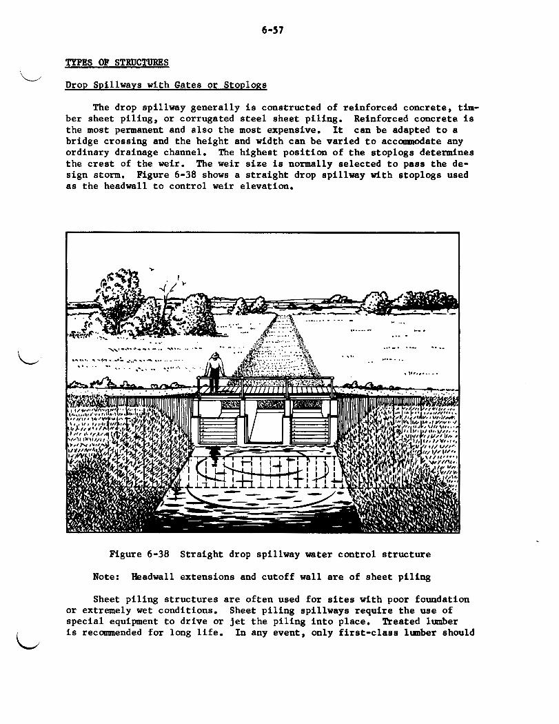
6-57
TYPES OF STRUCTURES
Drop Spillways with Gates or Stoplons L
The drop spillway generally i s constructed of reinforced concrete, t i m - ber sheet piling, or corrugated s tee l sheet piling. the most permanent and also the most expensive. It bridge crossing and the height and width can be varied t o accolrmodate any ordinary drainage channel. the crest of the w e i r . sign storm. as the headwall t o control w e i r elevation.
Reinforced concrete i s can be adapted t o a
The highest position of the stoplogs determines The weir size i s normally selected t o pass the de-
Figure 6-38 shows a straight drop spillway with stoplogs used
Figure 6-38 Straight drop spillway water control structure
Headwall extensions and cutoff wall are of sheet pil ing Note:
Sheet pil ing structures are often used for s i t e s with poor foundation or extremely wet conditions. special equipment t o drive or j e t the piling in to place. i s recommended for long l i f e .
Sheet pil ing spillways require the use of Treated lumber
In any event, only f i r s t -c lass lumber should

638
PREFABRICATED METAL STRUCTURE
-
SHEET PILING HEADWALL WITH APRON AND SIDEWALLS OF SAND-CEMENT BAGS
Figure 6-39 Small low cost water control structures

6-59
be used. Steel sheet pi l ing makes a permanent s t ructure i f properly in- s ta l led and protected. The cost i s similar t o reinforced concrete. A low- cost s t ructure consisting of a sheet pi l ing wall, an opening in to which stoplogs a re placed, and the apron and sidewalls b u i l t of sand-cement bags, is shown i n Figure 6-39. 1.5 t o 2.0 fee t deep or small trapezoidal ditches conrnonly used for sub- i r r iga t ion or i n wildl i fe areas. of prefabricated sheet metal structure tha t i s easy t o i n s t a l l and can be moved.
L This s t ructure i s w e l l adapted t o V-type ditches
Also shown i n Figure 6-39 i s one type
Box In l e t on Culvert with Gate or StoPlonp
This s t ructure combines a road culvert with a water control structure. The culvert may be of concrete, corrugated metal pipe or timber. i n l e t section i s generally made of reinforced concrete, timber, or a half- section of metal pipe. Figure 6-40.
The box
An example of t h i s type of s t ructure i s shown i n
Figure 6-40 Corrugated metal culvert water control s t ructures wlth concrete box i n l e t and stoplogs

6-60
Drop I n l e t Spillway with Stoplons
The pipe drop i n l e t spil lway can be used with an e a r t h dam embankment t o impound and cont ro l the depth of water by use of s toplogs placed in s ide the drop i n l e t . Examples of a f u l l sec t ion metal p i p e riser and a ha l f sec t ion metal pipe riser a r e shown i n Figure 6-41.
Drop I n l e t Spillways fo r Fish Management
By incorporating addi t iona l fea tures i n the drop i n l e t spi l lways, f i s h management can be provided. t o permit migration of f i s h upstream through the s t r u c t u r e , or provide for cool water r e l ease from a reservoi r f o r f i s h below the s t ruc ture .
Figure 6-42 shows necessary provis ions
&en Flumes
This is a box-type s t ruc tu re with the top s i d e open and s toplogs or
See Figure 6-43. a ga te i n s t a l l e d a t t h e upstream end fo r con t ro l l i ng the water level. It i s general ly constructed of concrete , timber or metal.
DESCRIPTION
Floodgates a r e devices fo r regula t ing the flow of water. They may be e i t h e r free-swinging ga te s t h a t serve a s automatic check valves or s l i d e ga tes operated manually or by power. Usually they a r e i n s t a l l e d a t t he end of a p i p e , or made pa r t of a concrete or wood s t r u c t u r e , located i n an e a r t h embankment b u i l t a s a dike or across a channel or drainage d i tch . The automatic ga te allows the water t o flow i n one d i r e c t i o n only, thereby preventing the water from flowing back i n t o the protected area. ure 6-44. d i r ec t ion a s desired. es tuary , i t is re fer red t o a s a t i d e gate.
See Fig- S l ide ga t e s may be used t o pe rmi t t he flow of water i n e i t h e r
When a floodgate s t r u c t u r e o u t l e t s i n t o , a n ocean
MATERIAL
Manufactured ga tes made from metal and attached t o corrugated metal pipes a r e the most widely used. Large metal or wood ga tes fabr ica ted i n both round and rectangular shapes a r e o f t en used i n loca t ions where they can be i n s t a l l e d a s pa r t of a wood or concrete s t ruc tu re .
FUNCTIONAL USES
1. A t t he end of a drainage d i t c h or flood channel where i t o u t l e t s i n t o a la rger stream t o prevent high s tages on the l a rge stream from backing up the d i t c h or channel.
LJ
2. In conjunction with pumped drainage o u t l e t s t o allow gravi ty flow when water s tages i n the o u t l e t a r e s u f f i c i e n t l y low and t o pre- vent high flow of t he o u t l e t channel from backing i n t o t h e pump i n s t a1 l a t ion.

6-6 1
L
L
.. ,.. ---_ ... A... -.-, -..... X1. .... \ .......-_
,>,..eclr).cU?w c- ..-- - -
Full section of pipe riser with stoplogs
I 1
PLANK WALKWAY
-V t + ' . , ' 4 * " 4
.Y
Half section of pipe riser with stoplogs
Figure 6-41 Corrugated metal pipe drop in let spillways for water level control by use of stoplogs i n the riser
L

6-62
Migration of f i s h upstream through structure - . __ --
Cool water release for f i s h below structure
Figure 6-42 Monolithic reinforced concrete drop i n l e t with provisions for f i s h management

6-63
Figure 6-43 Open timber flume with stoplog water level control
3. In out le t s through dikes i n t i d a l areas t o prevent inflow from the t ides and t o permit outflow from the in te r ior area when the t i d e lowers. During high t i d e the in t e r io r water i s stored.
ADAPTABILITY
Floodgates are best adapted t o locations where water stages on the
They a l so a re used along with out le t s i d e periodically a re low enough t o permit gravity disposal of run- off water i n a specified period of t i m e . pumps where enough gravity flow w i l l occur t o reduce the s ize of the pumps required or the amount of t i m e the pumps must be operated.
The var ie ty of s izes and types available permits f i t t i n g them t o s i te Floodgates instal led with pumping plants reduce the cost of requirements.
operation of the plant. tected land and i n some cases may eliminate the need for pumping.
Floodgates may be used t o prevent flooding of pro-
They can be ins ta l led with i n l e t controls t o maintain a de f in i t e water elevation for subirrigation, reducing subsidence of organic so i l s , or for providing water areas for wildl i fe developments.

6 -64
MkR
Figure 6-44 Automatic S
- -
me nter in draiayr ~ l l p is free t o flow t- the drainage pipe and be dircharged into outlet b i n . ever degree the drainage flow requires.
The gate autorrfically rtandr open t o a t -
0ATf CLOSED Dike I outirr
Lhlmga i r 6pty and tide or flood head in outlet badn i n above the dminago outlet 80 that the gate i r either p r t i a l l y or e o l l y mkged. Under t h u e conditiolvl the gate an tc r t i ca l ly r a i n r clored p.mtiag any baok flm into the -.
BATE CRACKED
Rm flood in outlet buin and an accmulatlon of drainage mter in the drainage w. Should the acomlatim in drainage mmp reach an elevation h-er than the flood or t ide in outlet basin the gate a u t c r t i o a l l j beccrer mcrackdn mfficiently to parit the drainage flow t o proceed unt i l the chainego head eqd.8 the t ide or flood head in outlet Win. The gate then sutcmatically cloeee od ramin 01-d until the drainage head again excwdr the tide or flood head in outlet barin.
winging floodgate
LIMITATIONS
Floodgates must be protected from debris t ha t could cause breakage or impair t he i r use. repair. open and close a s required. s ive dewatering work i f large wood or concrete s t ructures a re t o be in- s ta l led with gates. t o prevent erosion around the gate.
They must be inspected frequently and maintained i n good Automatic gates especially require maintenance t o insure tha t they
In many cases, s i t e conditions require exten-
Riprap or concrete headwalls are frequently required
1. Normally, the design of the outlet system should be based on the same drainage coeff ic ients as apply t o adjoining nontidal lands. However, the e f fec ts of prolonged wind t i d e s or r i ve r floodflows may require a high degree of protection from flooding i n the

6-65
L Time
L
- Hour Mnut e
A n 6 7 8
9
10
11
n 12
1
2
3
4 5
5
7 8
P M 9
02 00 00 00
00
01
00 02
00
06 00
00
58
00
00
00
w e Height
- Feet
3.0 3.8 3.5
2.8
1.5
0.2 -1.0
-1.7 -1.6
-1.3
-0.5
0.9
2.2
3.5 3.7
3.2
11 b i g h t Above - Wean Low Water
Feet
4.7 5.5 = R
-
5. 2 4.5
3.2
1.9
0.7
0.0 0.1
0.4 1.2
2.6
3.9
5.2 5.4 4.9
- -
3) Head - Gate on
Feet -
0
0.6
1.9
3.1 4.0
3.9 3.4
2.6 1.2 0
~~~ ~~
k/ Gate
Discharge
cf 8 -
0 @ 9ii36n 18.3
32.5
41.6
47.2 46.6
43.6
37.9
25. 9 0 @ 5H36M
1/ Mean law water - elevation -1.7 R - t i d a l range
- 2/
- 3/ 4/
Distance of design water elevation in gate forebay above mean law water (0.0 on tidal range)
Head on gate = E leas height above mean low water Discharge fo r selected 30" 0 gate from Figure 6-46
Figure 6-45 Tide gate design data

6-66
protected area. guidance.
See the S t a t e Standards and Spec i f ica t ions for
2. The highest allowable water sur face above the levee should be used as t h e bas i s for t he hydraulic design.
3. The da ta may be determined by d i r e c t observation a t t he s i te or obtained from recorded data obtained nearby. This data may be recorded as shown i n Figure 6-45, Tide ga t e design data,
4. By means of Figure 6-46, Capacity of c i r c u l a r ga t e s , determine the g a t e discharges fo r t he var ious heads on the gate.
5. Plo t a time-gate discharge curve and determine the a rea under the curve. This represents t h e t o t a l discharge f o r t h e t i d a l cycle.
6. Divide the t o t a l discharge by the t o t a l t i m e of t he cyc le t o ob- t a i n the average r a t e of discharge fo r t he ga t e s i z e selected.
7. I f t h e se lec ted ga te s ize does not meet t h e discharge require- ments determined i n item 1, reca l cu la t e f o r other g a t e s i z e s or use of mult iple gates.
Canplex o r la rge i n s t a l l a t i o n s requi re the a s s i s t ance of an engineer.
18. IRRIGATION STRUCTURES
St ruc tures play an important pa r t i n t he use and management of irri- ga t ion water, whether by open d i t c h or pipel ine. Various kinds of s t ruc - t u r e s are used fo r t he s torage , divers ion, d i s t r i b u t i o n and conveyance of water, and fo r erosion and grade control . For more d e t a i l e d information on i r r i g a t i o n s t ruc tu res r e f e r t o Chapter 3 - Planning Farm I r r i g a t i o n Systems, Section 15, N.E.H. and Standard plans developed by the States . Most la rge s torage, divers ion, and conveyance s t r u c t u r e s r equ i r e the a s s i s t ance of an engineer.
STORAGE STRUCTURES
St ruc tures fo r s to r ing i r r i g a t i o n water a r e c l a s s i f i e d as r e se rvo i r s f o r runoff s torage , offstream s torage , seepage s torage and regula t ing storage.
Runoff Storage
Reservoirs fo r s to r ing runoff water genera l ly are made by construct- They w i l l vary ing an e a r t h dam across a watercourse.
i n s i z e from small excavated farm ponds t o l a rge impounding main stream reservoi rs . Usually la rge r e se rvo i r s are b u i l t t o fu rn i sh water t o a group o r groups of farmers through a l ega l organizat ion, such as an irri- ga t ion or conservancy d i s t r i c t . use on s ing le farms or f i e lds .
(See Figure 6-37)
Small farm ponds usua l ly are b u i l t f o r

6-67
L
Gate 8i.e - Ioeher
Gate Area - Sq. It.
Hydr. llud - Feet
.2
.4
.6
.8
1.0 1.2 1.4
1.6 1.8 2.0
2.2 2.4 2.6 2.8 3.0
3.2 3.4 3.6 3.8
4.0 4.2 4.4 4.6 4.8 5.0 5.2 5.4 5.6
5.8 6.0 6.2 6.4 6.6
6.8 7.0 7.2 7.4
7.6 7.8 8.0
12 14 15 16 18 20 21 24 30 36 42 48 54
.79 1.07 1.23 1.40 1.77 2.18 2.41 3.14 4.91 7.07 9.62 12.57 15.90
1.70 2.40
2.94 3.40
3.80 4.16 4.49 4.65 5.10 5.37
5.64 5.89 6.13 6.36 6.58 6.80
7.01 7.21 7.41
7.60 7.79
7.97 8.15 8.33
8.50 8.67 8.83 9.00 9.16 9.31 9.46 9.61 9.76 9.91
2.30 3.25
3.98 4.60 5.15 5.64 6.08 6.30 6.91 7.28
1.64 7.98 8.30 8.61 8.91 9.21
9.49 9.77
10.04 10.29 10. 55 10.88 11.04 11.28 11.51 11.74
11 .w
12.19 12.40 12.60 12.82 13.02 13.23
13.43
2.64 3.74 4.58 5.29 5.92 6.48 6.99 7.24 7.95 8.36
8.78 9.18 9.53 9.90
10.25 10.59 10.91 11.23 i 1 . n
11.83 12.13 12.41
12.69 12.W 13.23
13.49 13.75
14.01 14.26 14.49 14.74 14.97 15.20
15.44
3.01 4.26 5.21 6.02 6.73 7.38 7.95 8.25 9.04 9.52
10.00 10.14 10.84 11.27 11.66 12.05
12.42 12.78 13.13
13.47 13.80 14.13
14.45 14.76 15.06
15.36 15.65
15.95 16.23 16.49 16.77 17.04 17.30 17.57
3.81 5.38 6.58 7.61
8.51 9.34
10.05
10.43 11.43 12.04 12.64 13.20 13.69 14.25 14.74 15.24 15.70 16.16 16.60
17.03 17.45 17.86 18.27 18.66 19.05
19.42 19.79
20.16 20.51 20.85 21.20 21.54 21.88 22.21
4.69 6.63 8.11 9.37
10.49 11.49 12.38 12.84 14.08 14.82 15.57 16.26 16.85 17. 55 18.16 18.77
19.34 19.90 20.45 20.97 21.49
22.00
22.50
22.98 23.46 23.91 24.37
24.83
25.27 2 5 . d 26.12
26.53 26.94 27.36
5.18 7.33 8.97
10.36
11.59 12.70 13.69 14.19 15.57 16.39 17.21 17.98 18.62 19.40 20.08 20.75 21.38 22.00 22.61 23.18 23.76
24.32 24.87 25.40 25.93
26.44 26.94
27.45 27.93 28.39 28.87
29.33 29.79 30.25
6.75 9.55
11.68 13.50 15.10 16.55 17.84
18.49 20.28 21.35 22.42 23.42 24.24 25.28 26.16 27.04
27.85 28.67 29.45 30.21 30.96
31.68 32.40 33.10 33.79
34.45
35.11 35.76 36.39 36.99 37.62
38.21 38.81
39.41
10.56 14.95 18.27 21.11 23.62 25.88 27.89
28.92 31.72 33.39 35.06 36.63 37.87 39.53 40.90 42.28
43.55 44.83 46. (#
47.23 48.41
4 9 . n 50.67 51.75 52.83
53.86
n . 8 9 55.92 56.91 57.84 58.82
59.75 60.69 61.62
15.20 21.54 26.30 30.40 34.01 37.26 40.16
41.64 45.67 48.08 50.48 52.74 n . 5 0 56.91 58.89 60.87 62.71 64.55 66.32 68.01
69.71 71.34
72.96 74.52 76.07
77.56
79.04 80.53 81.94 83.28 84'70
86.04 87.39 88.73
20.68 27.03 34.19 29.32 38.31 48.47 35.79 46.76 59.15 41.37 54.05 68.37 46.27 60.46 76.48 50.70 66.24 83.79 54.64 71.40 90.31
56.66 74.04 93.65 62.15 81.20 102.71 65.41 85.48 108.12 68.69 89.75 113.53 71.77 93.77 118.61 74.13 96.85 122.49 77.44 101.19 128.00 80.13 104.71 132.45 82.83 108.23 136.90 85.33 111.50 141.03 87.83 114.76 145.17 90.24 117.92 149.14 92.54 120.93 152.96 94.85 123.95 156.77 97.07 126.83 160.43
99.28 129.72 164.09 101.39 132.49 167.59 103.51 135.25 171.08
105.53 137.89 174.42
107.55 140.53 177.76 109.57 143.17 181.10 111.50 145.69 184.28 113.32 148.07 187.30 115.25 150.59 190.48 117.08 152.98 193.50 118.90 155.37 196.52 120.73 157.75 199.55
10.06 13.62 15.66 17.82 22.53 27.75 30.68 39.97 62.50 90.00 122.46 160.02 202.41 10.20 13.81 15.88 18.07 22.85 28.14 31.11 40.54 63.39 91.27 124.19 162.28 205.27 10.34 14.01 16.10 18.33 23.17 28.54 31.55 41.10 64.27 92.55 125.93 164.54 208.13 10.48 14.20 16.32 18.58 23.49 28.93 31.98 41.67 65.16 93.82 127.66 166.80 210.99 10.62 14.38 16.53 18.82 23.79 29.30 32.39 42.20 65.99 95.02 129.29 168.94 213.70
10.75 14.56 16.74 19.05 24.09 29.67 32.80 42.74 66.83 96.22 130.93 171.08 216.40
Bared an Q .6 A w- Pipa I l ~ r i n g Pull w i t h Cktlet &&merged
Iiwre 6-46 Capacity of circular gate.

Offstream Storage
Offstream storage should be considered i f streamflow i s not enough t o d provide the required amount of i r r iga t ion water or i f damning a stream i s not feasible. open di tch or pumped in to an offstream reservoir. by constructing an ear th dam across a draw or small val ley or by building a levee around an area of land.
Floodflow i n the stream may be diverted through a pipe or The reservoir i s made
Seepage Storage
Excavated reservoirs for intercepting and storing underground seepage water may be used i n some l o c a l i t i e s a s a water supply for i r r iga t ing small areas. The storage basin usually i s excavated i n a low-lying level area where the l a t e r a l mwement of water underground replenishes the supply. A dependable excavated reservoir requires a high natural water table under adjacent lands and a highly pervious layer permitting the rapid l a t e r a l movement of water within pract ical excavated depths, usually 12 t o 20 feet . The success of such a reservoir depends upon the rate of recharge because i t s capacity generally i s small.
Regulating Storage
Regulating reservoirs a re used where the stream i s too small for con- tinuous i r r igat ion. They are b u i l t e i ther by excavating a p i t and using the spoi l material t o build a levee around i t , or by building an earthen dam across a low area. Size is generally determined by the amount of wa- t e r needed for one day's operation. The reservoir should be large enough t o s tore a l l inflow while the i r r iga t ion system i s not i n operation. gation water may be supplied by pumping from a low-producing well, divert- ing flow from a spring, or continuous small del iver ies from canals and la te ra l s .
d Irri-
Often it is called an overnight-storage reservoir.
DIVERSION STRUCTURES
Where surface i r r iga t ion i s practiced, the source of water i s often the direct diversion of flow from a natural stream i n t o a conveyance canal or ditch. Although temporary measures may be used t o d iver t the water, a good system w i l l use a permanent s t ructure t o r a i se the water level i n the stream and force part of the flow i n t o the i r r iga t ion ditch. Many types of s t ructures a re used for t h i s purpose. The most coIIIpon i s one tha t uses stoplogs t o adjust water levels and the diversion of flow.
Figure 6-47 shows a stoplog type of concrete s t ructure used on creeks and small streams. Many s t a t e s use various versions of standard plans for t h i s type of structure. Some stoplog s t ructures have provisions for a pump ins ta l la t ion . These are used where water must be raised above the level of the stream or where the water i s moved d i r ec t ly in to a sprinkler system. Diversion s t ructures used on wide stream subject t o high floodflows may require provisions for the collapse of sections of the s t ructure during
.$he periods of high water t o safely pass the floodflows.

6-69
Figure 6-47 Stoplog type concrete diversion s t ructure
DITCH CCRWEPANCE STRUCTURES
Conveyance s t ructures a re used t o transport water across or under ob- s t ruct ions, such as swales, draws, or roads, and t o convey i t along steep h i l l s ides . They include flmes, inverted siphons, road culver ts , and bridges . Flumes
Flumes a r e a r t i f i c i a l channels, supported by a substructure, for carry- ing water across areas where ditches a re not pract ical . carry the water across draws or swales or t o convey it along steep or rocky h i l l s ides . These s t ructures must have the capacity t o carry the f u l l d i s - charge of the di tch, and the substructure must be strong enough t o support the flume when flowing fu l l . materials used for open flumes. closed flune.
They are used t o
Timber, metal, or concrete a re ordinar i ly t h e Long span s t ee l p i p e s may be used as a
Inverted Siphons
An inverted siphon i s a closed conduit with each end raised t o form a U-shaped s t ructure for carrying water under streams and drains or under roads and other obstructions. corrugated or smooth metal p i p e , concrete pipe or reinforced concrete
Inverted siphons usually a re constructed of

6-70
poured i n place. They a re par t icular ly adapted for conveying water under roads where the water level i n the i r r iga t ion d i tch i s carried above the ground. The inverted siphon i s different from a culvert i n that the top of the pipe i s lower than the water rurface at e i ther end, and the pipe always flows under pressure. See Figure 6-48
Figure 6-48 Crorr section of an inverted siphon
Ditch Crossings
Ditch crossing s t ructures for farm roads frequently a re necessary for access t o t h e f ie lds . Culverts are moot often used for t h i s purpose. Cor- rugated metal, smooth metal or cmcre te are most coapaonly ured for culverts. Inverted siphons a re adapted for crorrings where the 'cmter surface i n the di tch i s a t a higher elevation than the road. on large ditches. They can be b u i l t so there i s l i t t l e or no head loss through the structure.
Bridge8 a re more often used
EROSION CONTROL STRUCTURES
I r r iga t ion ditches a re rometiaes located where the d i tch w i l l have suf f ic ien t grade t o produce erosive ve loc i t ie r . be deposited downstream, thereby reducing the d i tch capacity. chutes, and pipelines a re used t o prevent such damages.
The eroded material w i l l Drops,
Drop Structures
The drop s t ructure is ured t o control the d i tch veloci ty by lowering the water abruptly from one level t o another. using a drop spillway or a pipe drop structure. of a standard plan for a concrete drop and Figure 6-50 shows a concrete block drop. Figure 6-51 i s an example of a corrugated metal pipe drop.
This may be accanplished by Figure 6-49 i s an example
Chutes
Chutes a re paved or lined high-velocity open channels. They are adapted t o short d i tch sections on steep slopes or where drop s t ructures would be so close together tha t a paved or lined d i tch would be more prac- t i c a l . The paving or l ining material for the chute must be able t o with- stand the high veloci t ies . Chutes are most often constructed of concrete. They a re complex i n design and require the assistance of an engineer. combination of a drop and chute, Figure 6-52, can sometimes be used where
A

6-71
Pbad won. 9‘
SECTIONAL ELEVATlOlY A-A
ELEVATION (DCTAIL OT SLDT IN EN0 SILL)
C
PLAN
TYE CLUCRETE F W T I W FOR UPIlRfAM NOTES YLL A D Dm(sTREAM WALL S U U Ic ?OURED
minsr COII~IDITEO YIWIAL. r r IYICUEII of THE marinas WWLL mi I LEIS TWI S I X I ICYI. THE TWICIIIESI DF W COIUFJE I N THE F Q Y D YLU W L L P T I€ La) IUI FIVE IWMI.
IWCYES. r r NIICUEII OF THE CLUUIETE i n I*L noon (us SHALL mi Y LOI IYU FQI
CONCRETE VERTICAL P . F M COHESIVE S a
. . .. .. I I~ ~- I I--
Figure 6-49 Plan for a concrete drop

6-72
I
WlAk OF SLOT IN EWO SILL)
-
SECTWAL ELEVATW A-A
REIHFWCEMEMT STEEL I1 CORCRETE F L D W TOEWALL AND CUTOFF WALL TO BE 3/8' O I U E T E R MIS PLACE0 AT CENTER OF SLAB AN0 SPACED AWUT'IZ' C-C BOTH U Y S ALL LONDlTlOlYL MIS TO BE BENT 1110 CUTOFF WALL AND TOEYILL. W U T I N T E D F W BARS.
6' X 4" 10. 6 I L k D WIRE YV I
W C R E T E Y D C N WALLS TO a t REINFORCED BY PLAC116 11011 TENSION STEEL WIRE KfSN I(0 WIRE, S l W l U R TO CARTER-WATERS BLON-MESH I N ALL HDRlZff lTAL BLOCK JOINTS Y W 6 .INCHES AT ALL SPLICES. SIOEYILLS WITH HEAD WALL So AS 10 EFFECTIVELV T I E THESE PARTS TOEETHLR. THE JOINT THICKNESS OENEEN W C R E T E MDCNS SYLL I E AWUT I / @ INCH THE COlCRtTC W N S SWLL BE UIO WITH STAMERE0 VERTICAL JDlHTS AS SWll ffl THE'PUNS OMllNU I N TIE BLOCNS U A L L BE AL IWEO VERTICALLY A10 FILLED WlTW CONCREiE PIOUT.
9 LAP Wlk
THE kESH S Y L L BE LAPPED S I X INCHES AT Jir*cllON OF
N E
T I E CONCRETE CUTOFF WALL AM0 TOWALL ARE TO BE P O R E 0 MAINST CONSOLIOATE0 W l E R l A L .
Q.&Ooh &
FOR COHESIVE SOILS ., . 6-10'
u. a UYPARTYRWC OF A O R I C U L T U ~ SOIL CONSERVATION SERVICE
Figwe 6-50 Plan for a concrete block drop

6-73
PLAN ISOMETRIC VIEW OF
GONCRETE SLAB (a00 noc No. 5)
SECTIONAL ELEVATiW ON CENTER LINE
. . - . - - , NOTES
I. SELECT A P IPE SIZE THAT WILL PROVIOL A OREATER CAPACITY TWAN I S REWIRE0 TO DlSCHAR6E THE WYIL STREAM USEO I(€# IRRIUTIY. 3 FPS U S E O ON IoI)(yL I R R l U T l l O STREW. W E N THE CONRWATED Y T A L PIPE MW I S USED AT A DITCH CROSSIM, INCREASE WIDTH OF TOP OF DAM A 1 0 OlYNSlON 1- BV B ' Q " .
TRY TO NEW TNE VELOCITY I N THE P IPE MLCU
2.
3. THE DROP (H) FOR ANY SPECI i lC STR&TkE CAN BE INCREASED 3 INCHES BY PLACING THE To) OF T I E RISER PIPE 3 INCHES IELCU THE TW Of TllE CONCRETE F L W OF THE INLET. THICKNESS OF THE FLOOR SLAB ADJACENT TO TW PIPE SWWLO BE INCREASED 3 INCHES TO MlE A WATERTI6IIT CONNECTION WITH TIE PIPE.
THE
THE INLET TO TUE P IPE YlWLO BE ROWDEO TO A 3 i icn RYIUS TO SAVE FORMIW Am IMPROVE THE EFFICIENCY OF THE IMLFT. . . _ _ _
1. THE DROP STRUCTURE I S FCUYO BY CUTTlM A STA10ARO LEN6TH OF CONRUMTED Y T A L P IPE WlCH I S YIIUFACTURED II ULTIPLES OF 2 FT. IN LEN6TH. OU A +So ANDLE Am WELDIIO +HE CUT JOINTS TOGETHER TO FORM A SV BEND. BETWEEN IIMIZONTAL AND VERTICAL PIECES OF PIPE TO BE WT WELDED A 1 0 WATERTIGHT. S I X INCH HANO PLACED RIP-RAP MY I E SUBSTITUTE0 FOR CONCRETE SLAB.
PIPE TO BE I8 01. CMRUWTED METAL. JOINT
5.
NWEHCLATURE ~ ~~
d - DEPTH OF WATER I N DITCH F - FREEBOARD I# DITCH 0 - D I A Y T E R DF PIP6 R - iEmiH-OF-VERTlcAL P IPE A L W CENTER L I Y
V - VELOCITY Of P IPE - FPS Q - DIXYROE THRWSH PIPE - C.F.S. N - DllW OF WATER SURFACE
i2- L E w n OF IIORIZONTAL PIPE A L ~ CENTER LINE
TABLE OF CONCRETE QUANTITIES D-IO' 0.25 CU.VOS. D-12' 0.26 CU.YW. O=l5' 0.29 CU.VD8. CORRUGATED METAL PIPE DROP
d s i 2 ' 1'. R. I ~ K I ~ M t T I I C : M ' OY Alil4llX'l .Tl'~K
€U)II. (X)SS.IER\'Xl'IOS SERVICE
1 ~ ~ ~ " I Figure 6-51 Plan for a corrugated metal pipe drop

6-74
fa-
s
S€CTIWAL ELEVATION C-C UddIhEdSI
SECTIONAL ELEVATION 0-0
Figure 6-5* Plan for a trapezoidal chute drop
'LJ
LJ

6-79
it i s necessary t o take up grade i n a short distance l i k e the drop between benches. L DISTRIBUTION CONTROL STRUCTURES
Distribution control s t ructures a re required for easy and accurate d i s t r ibu t ion of i r r i g a t i o n water t o the various f i e lds on the farm. control of the water permits e f f i c i en t d i s t r ibu t ion and application and reduces the labor requirements, Distribution control s t ructures include headgates, divis ion boxes, checks, and turnouts.
Good
Farm Headnates
The farm headgate is a gate-type s t ructure used t o d iver t the required amount of i r r i g a t i o n water from the farm source of supply i n t o the farm f i e ld ditches. water-measuring device t o determine the flow i n t o the f i e ld ditch. Figure 6-53 i s an example of a plan for a concrete headgate.
The headgate i s generally equipped with some type of
Division Boxes
A divis ion box is a s t ruc ture used t o d i v i d e or d i r ec t the flow of water i n t o two or more ditches. flow entering through an opening on one side. ings equipped with gates of the required size t o furnish the necessary flow t o the f i e ld ditches. See Figure 6-54. Division boxes a re used a l so w i t h pmp ins t a l l a t ions t o control the flow fran the pump i n t o one of two or more f i e l d ditches. Figure 6-55 shows a combination p m p out le t and divi- sion box.
It i s a box s t ruc ture with the supply The other sides have open-
Checks
A check is a s t ructure placed i n a d i t ch t o control the elevation of the water surface above the structure. The water level is raised as neces- sary so tha t it can be diverted from the ditch. Checks a re e i ther portable or permanent. purpose for i r r iga t ing a given area and are rese t for i r r iga t ing another area. of canvas, p l a s t i c , rubber, or metal. A permanent check is a headwall w i t h a weir-type opening equipped with stoplogs or s l i d e gates for adjusting the upstream elevation of the water surface, for one type of concrete check.
Portable checks a re removed a f t e r they have served the i r
The portable check is avai lable coamercially and i s generally made
Figure 6-56 is a standard plan
Turnouts
The turnout is a box or orifice-type s t ruc ture located i n the bank of the head d i tch for controll ing the flow of water from the head di tch in to border s t r i p s , contour levee areas, and contour ditches. The s t ructure i s equipped with a s imple s l i d e gate for regulating the flow. Wooden or con- c re t e boxes and concrete or metal pipe are generally used for turnouts. An example of a plan for a concrete turnout is shown i n Figure 6-57.

6-76
2. 58
I 8*/#2"
ELEVATION A-A HEAOBATE NOT SHOWN
w j 6""
SECTIONAL ELEVATION 6 - 8 HEAOGATE NOT SHOWN
CONCRETE HEADGATE STRUCTURE 8 . )'-on 4 ' - ~ ' 6'-0"
U. H. 1W:PARTYENT OF AORICI'I.TCRK SOIL CONSERVATION SERVICE
7 I 1-04 sp-lap00.u-l I
Figure 6-53 Plan for a concrete headgate

1078 31V9 d0 1IVlM
8-8 NOllVA313 lVNO1133S
M
f L-9

6-78
ISOMETRIC
DETAIL of GATE SLOT AND BAFFLE SLOT
DETAIL OF WOOD BAFFLE
TABLE OF QUANTITIES LUMBER L. FT. WIRE YEW CONCRETE mJ
1 t Without ogronc
79 I 1.3
*In cohoiivo soil, whon w t l o t i ore O@ o p ~ o i i t o lidor, Ooroni moy bo onittod
d = Oopth of flow in ditch f * Frooboord from wotor iurfoco to
top of ditch bonk
d 112" CoPocity 600 - 1000 0. R Y.
COMBINATION PUMP OUTLET AND DIVISION BOX
8'- 0'

6-79
L
L
Figure 6-56 Plan for a concrete check
L

6-80
ISOMETRIC VIEW
SECTION A-A
k PLAN
DETAIL OF GATE SLOT
Conerote quontity = 0.44 cu yd.
NOMENCLATURE B *Bonorn width of structure b *Dotton wldm of ditch d = bpth d w o t r In dltch
SECTIONAL ELEVATION 8-8
CONCRETE TURNOUT d - I f B 1'-6.
U. #I. UKPARTNKNT OF ACIIICNIXCRK BOIL CONSERVATION SERVICE
I h
r 1 - 1 1-64 SQ-lOpOO IT- SECTIONAL ELEVATW C-C
- 8 . . I. .... Hgure 6 3 7 Plan for a concrete turnout

6-81
PIPELINE STRUCTURES
The d is t r ibu t ion of i r r iga t ion water by means of low-head underground
I n pipelines has many advantages i n conserving s o i l , water and labor. On sloping lands, erosion that could occur i n open ditches i s eliminated. a properly designed system with sealed jo in ts , the loss of water by seepage i s reduced t o minor amounts. tha t a re used t o quickly t u r a water on and off or t o s h i f t the delivery t o other points.
Labor can be saved by means of the controls
Some typical exemples of the s t ructures camonly used i n pipeline systems a re described i n the following paragraphs.
I n l e t s t o move water from a supply source i n t o the pipe a re f i r s t s t ructures i n a system. stand such as i n Figures 6-58 or 6-59 may be used. be taken d i r e c t l y from an i r r iga t ion ditch, a simple i n l e t such a s tha t i n Figure 6-60 can be used. Sometimes, water from an open d i tch contains sed i - ment, small debris, or weed seeds tha t could create problems. In t h i s event, s t ructures such a s those i n Figure 6-61 are used t o sett le and screen out the objectionable materials a t the in l e t . t rap such as that i n Figure 6-62 may be placed i n the system.
Where water i s obtained by ptnping, a pump i n l e t I f clean water i s t o
Or , i n cases of sand only, a
Vents - A i r trapped i n pipelines can cause e r r a t i c flow conditions. To pre-
vent t h i s , vents are used a t high points i n the l i nes and where the l i ne makes abrupt changes i n grade. Figure 6-63.
A simple type of vent is i l l u s t r a t ed i n
Outlets
I n any pipeline. system, out le t s are used t o control the discharge of wa- ter a t selected points i n the area t o be i r r igated. valves a re the Alfalfa Valve, Figure 6-64, and the Orchard Valve, Figure 6-65.
The two most cormon
Further discussion and examples of pipeline s t ructures can be found i n Chapter 3, Section 15, N.E.H. Also, local ly adopted standard plans may be available.
19. STRUCTURE DESIGN
After information needed for a s t ructure design has been obtained by a f ie ld survey, it and other pertinent information should be recorded on a s t ructure data sheet or plan. A l l recorded information, calculations, and design data should be checked for accuracy.
The detailed s t ructure design develops the overall plan for the struc- ture as indicated on the s t ructure data sheet. Such items as dimensions of the various parts of the s t ructure , spacing of steel reinforcing bars i n
id

6-82
Figure 6-58 Plan for high head non- tapered pump stand for
concrete pipe
-
E
HIOH HEAD NON-TAPERED PUMP STAIlo FOR CONCRETE PIPE
1'. N. IBKI*AI*NKST 4W A(lNHX'I.71'NK HOlL C4)SHKRVATIOS OKRVICK
--.I
I
&on indicoird in % CROSS SECTION t o b k k k . .
PLAN
Rrmovoblr covrr (0piionol)I
I I I I I I I I I I I I I I I I I I I I I I I I I I I
I l~
I I 1 I I I I I
I I I
E L EVA1 I0 N mom:
1. y h m D S 2 7 ' a r h * , ~ nglwtor than D diminoto flop mtr ond usr o
C k h wlvr in pump dirchorq. pip..
d
d

6-83
L
L
DI
CROSS SECTION
NOrt lCL ATURC:
D - o 1 0 1 1 1 * 0 ( ~ W l C N h P P
DI- obrrlr of llbqond oi#
h--dw-log,OPI
o r Dlcrr)r d repr 0-1 - *. ~ - - 0 ( b u rnoWaaplO.
* - t w c r * r d e m b # r
O - m - - b C * S b m oo(n.
Figure 6-59 Plan for a high head steel tapered pump stand for
concrete p i p e

6-84
1
4nkt
ELEVATION
NOMENCLATURE 6 a Dlpth of rotor in d i m F= hnboord in ditch O= Diomotw of vrrtlcol pip. 0,- Diomotr of undorglornd plm t = Thlchnooo of eoncrrtr bow )I = M r i ht d vor(ioai pipr .borr
0 a D#Ow thmmgh *rrrcIIIn ct0.d spn t W 3 aonwot. borr
I ORAVITY INLET
B(llL C X I " A T I 0 N glcRVKa
Figure 6-60 Plan for a gravity inletfor concrete pipe

6-85
.. i/r WEIR PLITE E1Q I
GENTERL IN€
38'- L T r , S 4 J
0 B
IRRIGATION WATER DESlLTlNG BOX AND TRASH SCREEN
TABLE OF QUANTITIES _ _ -_ ITEM UNIT
p i i i C R i T € W_.!DS. LlW.FT.
OD YEIN CWPER SCREEW W.FT.
M.FT. I/@' YARWIRE CLDR W.!T.
EAU EUW rra I?" PIPE PLUO E I u l
,6" D I I . PIP€. 1'-4- L Q O EACH UCW 14- PIPE ELDW
S I M VIEW WNI. (XXV1IEHVATIOS WKHVl(:K
i 1 PETAIL OI TRASH SCrY;rr

6-86
COllCRfTf PIPE SAW0 TRAP FOR CONCRETE PIPE LlWf I?. a OW-IICI ~ IP kolmwt-ag
BOIL <XIWRILR\'ATION BILIIVKX I ~~- I Figure 6-62 Plan for a concrete pipe sand trap for concrete pipe

L
L

6-88
Oponmg brohon out
w+
WOMENCLATUllE 0-Diamotor of r i r r pip. and
nominal diamotor of alfdfa c t o 01- Diamotr of undorqound cancroto
PLAN Pip.
001a#nlng kohon out
Alfalfa rolvo or Alfalfa valve or modifiod alfalfa
c CROSS SECTON CROSS SECTION Rocommataod when vobcity in r * r Rocommondod whon velocity oxceodr 3.5foot por rcand and hy&an)r
a n not lmod. por rocand or whrn hydrant8
TYPE I TYPE XE
in rlror I8 lo88 than 3.5 foot
aro usad.
ALFALFA mLVE or MODIFIED ALFALFA VALVE OUTLET tor CONCAETE PlPE LINES Figure 6-64 Plan for an a l fa l fa
valve outlet on a concrete pipeline
I'. Ic UKPARl'YKST (IF AOR1CTI.TI'RK O I L CI)NIER\'ATION 86RVICE

6-89
Notch broken
-.
PLAN
TYPE I
% CROSS SECTION
NOMENCLATURE
D - Diometer of concrete riser pipe
0, - Diometer of underground concrete pipe
D, - Diometer of volve outlet
h - Height of hydraulic grode line above field rurfoce
Concrete plpe with overflow notch broken in ride
rHydroulic grode line -, A
Design "Oter rurfoce 7 Orchard volve -,
TYPE H
Q CROSS SECTION
Figure 6-65 Plan for an orchard valve out le t on a
ORCHARD VALVE OUTLET
SOIL CONSERVATION SERVICE concrete pipeline

6-90
reinforced concrete, and location of construction joints are examples of required detail. Detailed designs are the responsibility of the engineer.
In the Soil Conservation Service two types of structure designs are used :
1. Standard designs. various combinations of conditions. Some standard designs or plans have blank spaces for fill-in dimensions and quantities, thus they can be adapted to a given location. standard structure designs should be made only by an engineer having that authority.
These are designs prepared in advance to fit
Modifications in
2. Special designs. These are prepared to fit the site when stand- ard designs are not applicable. They are "tailor-made" designs, made after properly prepared and approved data sheets have been submitted to the design engineer.
20. CONSTRUCTION
Adequate structure designs and plans will not make a good structure unless sound construction techniques are used during its installation. Chapter 17 of this manual provides these techniques. to follow all specifications accompanying the structure plans.
It is also necessary
Good quality construction can be promoted by laying the proper ground- work with the farmer. This involves:
1. Emphasizing the need for using construction materials of accepta- ble quality.
2. Emphasizing the importance of building the structure as planned and designed.
Timely technical assistance should be given both before and during the actual construction by:
1. Providing sufficient stakes for construction purposes, and check- ing the staking.
2. Explaining the stakes to the farmer and the contractor, making sure they understand their purpose and the need for protecting them.
3. Providing the farmer and contractor with plans and specifications prior to construction.
4. Explaining the construction details to the farmer or contractor.
d
5. Providing timely supervision and checking during the construction period .

6-91
21. MAINTENANCE
All structures need maintenance for satisfactory operation and to prolong their life, thereby reducing replacement cost. Owners should be urged to inspect structures at least once annually and at other opportune times. Cracks that develop should be sealed, protective coatings applied where needed, and modifications, riprap, or repairs made where and when they are necessaryo Often a small repair job will prevent a large repair job, or even complete failure, later on. Debris or obstructions at the inlet or outlet of structures should be removed immediately. Check for destructive action of burrowing rodents under the structure and through ad- jacent earth embankments.
For preventative maintenance protect the structure from livestock. Maintain all earthfills and channels in good sod by mowing, reseeding and fertilizing.