engineering metrology & measurements notes
DESCRIPTION
EngTRANSCRIPT
SCAD ENGINEERING COLLEGEME6504 Metrology and Measurements
Unit 1Basic Concepts of
Measurements
Metrology is the name given to the science of puremeasurement. Engineering Metrology is restricted tomeasurements of length & angle.
Need for Measurement
to ensure that the part to be measured conforms tothe established standard.
to meet the interchangeability of manufacture. to provide customer satisfaction by ensuring that no
faulty product reaches the customers. to coordinate the functions of quality control,
production, procurement & other departments of theorganization.
to judge the possibility of making some of thedefective parts acceptable after minor repairs.
Precision & Accuracy of Measurement
Precision : It is the degree which determines how wellidentically performed measurements agree with each other.It is the repeatability of the measuring process. It carries nomeaning for only one measurement. It exists only when aset of observations is gathered for the same quantity under
identical conditions. In such a set, the observations willscatter about a mean. The less is the scattering, the moreprecise is the measurement.
Accuracy : It is the degree of agreement between themeasured value and it’s true value. The difference betweenthe measured value & the true value is known as ‘Error ofmeasurement’. Accuracy is the quality of conformity.To distinguish the Precision from Accuracy, the followingsimple example can be said. A repaired needle-watch willgive Precision readings (same time) all the times, but willgive Accurate readings (correct time) only 2 times in a day.
Of the two, Precision & Accuracy, only the former isrequired though the latter is usually sought for in ameasuring process. Achieving high precision is easier &cheaper than achieving high accuracy. If the measuringinstrument is of high precise & is calibrated for its error,then the true value can be easily obtained from themeasured average value after deducting the instrumenterror. So, high precision - instrument is required ratherthan the high accurate – instrument, considering cost andreliability of the measuring instrument.
However, of the two, precision & accuracy, which one ismore vital, depends on the situation. For example, for acarpenter entrusted with the job of fitting a shelf intocupboard, precision is more important. This can beachieved only when he uses the same scale to measure thecupboard & the board for shelf. It hardly matters whetherhis scale is accurate or not. If however, such a board isordered for purchase from a pre-cut board from outside,accuracy becomes more vital than precision. He mustmeasure the size of the cupboard very accurately beforeplacing the order.
‘Interchangeability’ is the call of the day. Not only a nutfrom its lot should fit on any bolt of its lot, both
manufactured in the same plant by same men, but also, itshould fit on a bolt from some other manufacturer. Thesimplest way to maintain compatibility of parts forinterchangeable manufacture is by adopting accuracy inmeasurement everywhere.Factors affecting the accuracy of measuring system
a) Factors affecting the standard of measurement: co-efficient of thermal expansion elastic properties stability with time geometric compatibility
b) Factors affecting the work piece to be measured: co-efficient of thermal expansion elastic properties arrangement of supporting work piece hidden geometry surface defects such as scratches, waviness, etc.
c) Factors affecting the inherent characteristics ofinstrument:
repeatability & readability calibration errors effect of friction, backlash, etc inadequate amplification for accuracy objective deformation in handling or use
d) Factors affecting person: improper training / skill inability to select proper standards / instruments less attitude towards personal accuracy
measurements
e) Factors affecting environment: temperature, humidity, atmospheric pressure, etc. cleanliness adequate illumination heat radiation from lights / heating elements
Reliability of Measurement
If a measuring instrument is not precise, it will givedifferent values for same dimension, when measured againand again. Such an instrument thus is considered non-trustworthy. The first and fundamental requirement of any goodmeasuring instrument to be effective is that it should haveadequate repeatability or precision. The measuringinstrument which gives precise (same) values all the timesis far reliable than the instrument which gives accurate(true) values rarely but not precise values all the times. Theprecise value can be easily converted into accurate value bytaking the constant error of precision instrument intoaccount.
If the precision measuring instrument is highly calibratedfor its error of measurement & the constant error ofmeasurement is known in advance, then the accurate (true)value can be obtained as follows ;
True value = Measured value ± Error
Hence, calibrated & precision measuring instrument ismore reliable and hence is used in metrological laboratories.
Methods of Measurement
1) Method of direct measurement: The value of thequantity to be measured is obtained directly without thenecessity of carrying out supplementary calculations basedon a functional dependence of the quantity to be measuredin relation to the quantities actually measured. Example :Weight of a substance is measured directly using a physicalbalance.
2) Method of indirect measurement: The value of thequantity is obtained from measurements carried out by
direct method of measurement of other quantities,connected with the quantity to be measured by a knownrelationship. Example : Weight of a substance is measuredby measuring the length, breadth & height of the substancedirectly and then by using the relationWeight = Length x Breadth x Height x Density
3) Method of measurement without contact: The sensor isnot placed in contact with the object whose characteristicsare being measured.
4) Method of combination measurement closed series: Theresults of direct or indirect measurement or differentcombinations of those values are made use of & thecorresponding system of equations is solved.
5) Method of fundamental measurement: Based on themeasurements of base quantities entering into the definitionof the quantity.
6) Method of measurement by comparison: Based on thecomparison of the value of a quantity to be measured with aknown value of the same quantity (direct comparison), or aknown value of another quantity which is a function of thequantity to be measured (indirect comparison).
7) Method of measurement by substitution: The value of aquantity to be measured is replaced by a known value ofthe same quantity, so selected that the effects produced inthe indicating device by these two values are the same (atype of direct comparison).
8) Method of measurement by transposition : The value ofthe quantity to be measured is in the beginning, balancedby a first known value A of the same quantity, then thevalue of the quantity to be measured is put in place of thisknown value and is again balanced by another known valueB. If the position of the element indicating equilibrium isthe same in both the cases, the value of the quantitymeasured is equal to A & B.
9) Method of differential measurement: Based on thecomparison of the quantity to be measured with a quantityof the same kind, with a value known to be slightlydifference from that of the quantity to be measured, and themeasurement of the difference between the values of thesetwo quantities.
10) Method of measurement by complement: The value ofthe quantity to be measured is complemented by a knownvalue of the same quantity, selected in such a way that thesum of these two values is equal to a certain value ofcomparison fixed in advance.
11) Method of measurement by interpolation : It consists ofdetermining value of the quantity measured on the basis ofthe law of correspondence & known values of the samequantity, the value to be determined lying between twoknown values.
12) Method of measurement by extrapolation : It consistsof determining the value of the quantity measured on thebasis of the law of correspondence & known values of thesame quantity, the value to be determined lying outside theknown values.
Terms in Measurement
1) Constant of a measuring instrument: The factor by whichthe indication of the instrument shall be multiplied toobtain the result of measurement.
2) Nominal value of a physical measure: The value of thequantity reproduced by the physical measure and isindicated on that measure.
3) Conventional true value of a physical measure: Thevalue of the quantity reproduced by the physical measure,determined by a measurement carried out with the help ofmeasuring instruments, which show a total error which ispractically negligible.
4) Standard: It is the physical embodiment of a unit. Forevery kind of quantity to be measured, there should be aunit to express the result of the measurement & a standardto enable the measurement.
5) Calibration: It is the process of determining the values ofthe quantity being measured corresponding to a pre-established arbitrary scale. It is the measurement ofmeasuring instrument. The quantity to be measured is the‘input’ to the measuring instrument.The ‘input’ affects some ‘parameter’ which is the ‘output’ &is read out. The amount of ‘output’ is governed by that of‘input’. Before we can read any instrument, a ‘scale’ mustbe framed for the ‘output’ by successive application of somealready standardised (inputs) signals. This process isknown as ‘calibration’.
6) Sensitivity of instrument: The ability of the instrumentto detect small variation in the input signal.
7) Readability of instrument: The susceptibility of ameasuring instrument to having its indications converted toa meaningful number. It implies the ease with whichobservations can be made accurately.
Standards of Measurement
a) FPS System: In this system, the units of length, mass,time, temperature are Foot (or Yard), Pound (or Slug),Second, Rankine (or Fahrenheit) respectively. It is commonin English speaking countries and is developed by Britain.
b) Metric System: It is a decimal system of weight &measurement is based on the Metre as the unit of length. Itwas first used in France. Its basic unit is Metre.
CGS prescribes Centimetre, Gram, Second for length,weight & time respectively.
MKS prescribes Metre, Kilogram, Second for length, weight& time respectively.
MKSA (Giorgi) system added Ampere, the unit of electricalcurrent to MKS system.
c) SI system: In 1960, General Conference on Weights &Measures (CGPM) formally gave the MKSA, the title‘’Systems International d’ unites’’ with the abbreviation ‘SI’(also called as International System of units). In SI, themain departure from the traditional metric system is the useof ‘Newton’ as the unit of Force. India by Act of ParliamentNo.89, 1956 switched over to SI system.
Basic units in SI system
1) For Length : Metre (m) which is equal to 1650763.73wavelengths in vacuum of the red-orange radiationcorresponding to the transition between the levels 2p10 &5d5 of the krypton-86 atom. (Definition by wavelengthstandard)
By Line standard, Metre is the distance between the axes oftwo lines engraved on a polished surface of the Platinum –Iridium bar ‘M’ (90% platinum & 10% iridium) kept atBureau of Weights & Measures (BIPM) at Sevres near Parisat 0C, the bar kept under normal atmospheric pressure,supported by two rollers of at least 1 cm diametersymmetrically situated in the same horizontal plane at adistance of 588.9 mm (Airy points) so as to give minimumdeflection.
2) For Mass: Kilogram (kg) which is equal to the mass ofInternational prototype of the kilogram.
3) For Time : Second (s) which is equal to the duration of9192631770 periods of the radiation corresponding to the
transition between the hyper fine levels of the ground stateof the Caesium 133 atom.
4) For Current : Ampere (A) is that constant current which,if maintained in two straight parallel conductors of infinitelength of negligible circular cross section & placed onemetre apart in vacuum would produce between theseconductors, a force equal to 2 x 10⁻⁷ Newton per unit length.
5) For Temperature: Kelvin (K) is the fraction 1/273 ofthermodynamic temperature of the triple point of water.
6) For Luminous intensity: Candela (cd) is the luminousintensity in the perpendicular direction of a surface of1/6,00,000 m2 of a black body at the temperature of freezingplatinum under a pressure of 101325 N/m2.
7) For amount of substance: Mole (mol) is the amount ofsubstance of a system which contains as many elementaryentities as there are atoms in 0.012 kg of Carbon-12.
Supplementary SI units:1) For Plane angle: Radian (rad)2) For Solid angle: Steradian (sr)
Derived SI units:1) For Frequency: Hertz (1 Hz = 1 cycle per second)2) For Force: Newton (1 N = 1 kg-m/s2)3) For Energy: Joule (1 J = 1 N-m)4) For Power: Watt (1 W = 1 J/s)
Classification of Standards
1) Line & End Standards: In the Line standard, the length isthe distance between the centres of engraved lines whereasin End standard, it is the distance between the end faces of
the standard. Example : for Line standard is MeasuringScale, for End standard is Block gauge.
2) Primary, Secondary, Tertiary & Working Standards:Primary standard: It is only one material standard and ispreserved under the most careful conditions and is usedonly for comparison with Secondary standard.Secondary standard: It is similar to Primary standard asnearly as possible and is distributed to a number of placesfor safe custody and is used for occasional comparison withTertiary standards.Tertiary standard: It is used for reference purposes inlaboratories and workshops and is used for comparisonwith working standard.Working standard: It is used daily in laboratories andworkshops. Low grades of materials may be used.
Errors in Measurement
Error in measurement is the difference between themeasured value and the true value of the measureddimension.Error in measurement = Measured value – True value
The error in measurement may be expressed as an absoluteerror or as a relative error.
1) Absolute error: It is the algebraic difference between themeasured value and the true value of the quantitymeasured. It is further classified as;
a) True absolute error: It is the algebraic difference betweenthe measured average value and the conventional truevalue of the quantity measured.
b) Apparent absolute error: It is the algebraic differencebetween one of the measured values of the series ofmeasurements and the arithmetic mean of all measuredvalues in that series.
2) Relative error: It is the quotient of the absolute errorand the value of comparison (which may be true value,conventional true value or arithmetic mean value of a seriesof measurements) used for the calculation of that absoluteerror.
Example : If the actual (true) value is 5,000 and estimated(measured) value is 4,500, find absolute and relative errors.Solution : Absolute error = True value – Measured value
= 5,000 – 4,500= 500 units
Relative error = Absolute error / Measured value= 500 / 4,500= 0.11 (11%)
Types of Errors
A) Error of Measurement
1) Systematic error: It is the error which during severalmeasurements, made under the same conditions, of thesame value of a certain quantity, remains constant inabsolute value and sign or varies in a predictable way inaccordance with a specified law when the conditionschange.The causes of these errors may be known or unknown. Theerrors may be constant or variable. Systematic errors areregularly repetitive in nature.
2) Random error: This error varies in an unpredictablemanner in absolute value & in sign when a large number ofmeasurements of the same value of a quantity are madeunder practically identical conditions. Random errors arenon-consistent. Random errors are normally of limited timeduration.
3) Parasitic error: It is the error, often gross, which resultsfrom incorrect execution of measurement.
B) Instrumental error
1) Error of a physical measure: It is the difference betweenthe nominal value and the conventional true valuereproduced by the physical measure.
2) Error of a measuring mechanism: It is the differencebetween the value indicated by the measuring mechanismand the conventional true value of the measured quantity.
3) Zero error: It is the indication of a measuring instrumentfor the zero value of the quantity measured.
4) Calibration error of a physical measure: It is thedifference between the conventional true value reproducedby the physical measure and the nominal value of thatmeasure.
5) Complementary error of a measuring instrument: It isthe error of a measuring instrument arising from the factthat the values of the influence quantities are different fromthose corresponding to the reference conditions.
6) Error of indication of a measuring instrument: It is thedifference between the measured values of a quantity, whenan influence quantity takes successively two specifiedvalues, without changing the quantity measured.
7) Error due to temperature: It is the error arising from thefact that the temperature of instrument does not maintainits reference value.
8) Error due to friction: It is the error due to the frictionbetween the moving parts of the measuring instruments.
9) Error due to inertia: It is the error due to the inertia(mechanical, thermal or otherwise) of the parts of themeasuring instrument.
C) Error of observation
1) Reading error: It is the error of observation resultingfrom incorrect reading of the indication of a measuringinstrument by the observer.
2) Parallax error: It is the reading error which is produced,when, with the index at a certain distance from the surfaceof scale, the reading is not made in the direction ofobservation provided for the instrument used.3) Interpolation error: It is the reading error resulting fromthe inexact evaluation of the position of the index withregard to two adjacent graduation marks between whichthe index is located.
D) Based on nature of errors
1) Systematic error: (already discussed)
2) Random error: (already discussed)
3) Illegitimate error: As the name implies, it should notexist. These include mistakes and blunders, computationalerrors and chaotic errors. Chaotic errors are random errorsbut unlike the latter, they create chaos in the final results.
E) Based on control
1) Controllable errors: The sources of error are known andit is possible to have a control on these sources. These canbe calibration errors, environmental errors and errors dueto non-similarity of condition while calibrating andmeasuring.
Calibration errors: These are caused due to variation in thecalibrated scale from its normal value. The actual length ofstandards such as slip gauges will vary from the nominalvalue by a small amount. This will cause an error ofconstant magnitude.
Environmental (Ambient /Atmospheric Condition) Errors:International agreement has been reached on ambient
condition which is at 20C temperature, 760 mm of Hgpressure and 10 mm of Hg humidity. Instruments arecalibrated at these conditions. If there is any variation inthe ambient condition, errors may creep into final results.Of the three, temperature effect is most considerable.
Stylus pressure errors: Though the pressure involvedduring measurement is generally small, this is sufficientenough to cause appreciable deformation of both the stylusand the work piece. This will cause an error in themeasurement.
Avoidable errors: These errors may occur due to parallax inthe reading of measuring instruments. This occurs whenthe scale and pointer are separated relative to one another.
The two common practices to minimise this error are:i) reduce the separation between the scale and pointer tominimum.ii) a mirror is placed behind the pointer to ensure normalreading of the scale in all the cases.These avoidable errors occur also due to non-alignment ofwork piece centres, improper location of measuringinstruments, etc.
2) Non-controllable errors: These are random errors whichare not controllable.
Causes of Errors
1) Errors due to deflection (Errors of supports): When longbars are supported as beam, they get deformed or deflected.This elastic deformation occurs because long bars,supported as to ends sags under their own weight. Theamount of deflection depends upon the positions of thesupports. This problem was considered by Sir G.B. Airy,who showed that the positions of the supports can bearranged to give a minimum error. Slope and deflection atany point can be calculated from the theory of bending.
Two conditions are considered, as follows; For a bar oflength L, supported equidistant from the centre on supportsby distance ‘l’ apart, then for no slopes at the ends,l = 0.577 L (suitable for line standards and end bars). Forminimum deflection of the beam, l = 0.544 L (suitable forstraight edges)
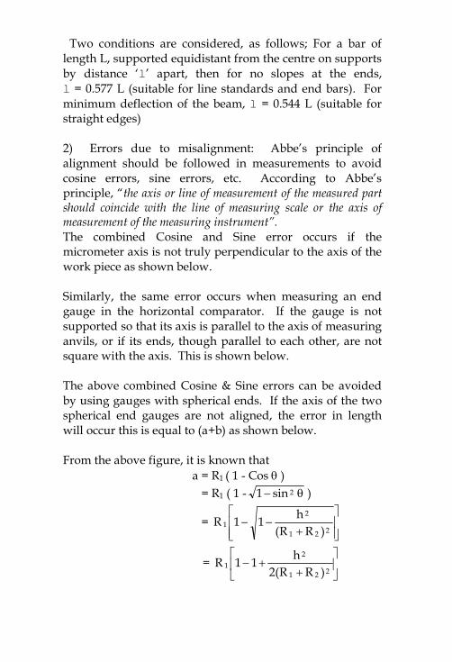
2) Errors due to misalignment: Abbe’s principle ofalignment should be followed in measurements to avoidcosine errors, sine errors, etc. According to Abbe’sprinciple, “the axis or line of measurement of the measured partshould coincide with the line of measuring scale or the axis ofmeasurement of the measuring instrument”.The combined Cosine and Sine error occurs if themicrometer axis is not truly perpendicular to the axis of thework piece as shown below.
Similarly, the same error occurs when measuring an endgauge in the horizontal comparator. If the gauge is notsupported so that its axis is parallel to the axis of measuringanvils, or if its ends, though parallel to each other, are notsquare with the axis. This is shown below.
The above combined Cosine & Sine errors can be avoidedby using gauges with spherical ends. If the axis of the twospherical end gauges are not aligned, the error in lengthwill occur this is equal to (a+b) as shown below.
From the above figure, it is known thata = R1 ( 1 - Cos )
= R1 ( 1 - 2sin1 )
=
221
21
)RR(h11R
=
221
21
)RR(2h11R
=221
21
)RR(2hR
very nearly
Similarly, b =221
22
)RR(2hR
Therefore, (a+b) =221
221
)RR(2h)RR(
=)RR(2
h21
2
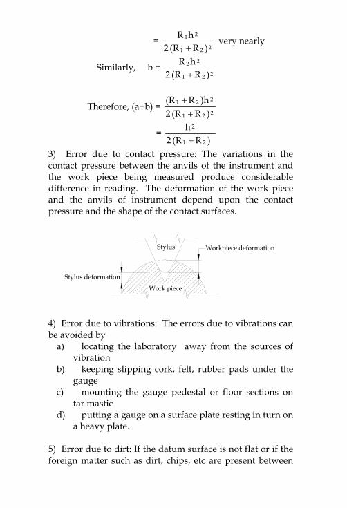
3) Error due to contact pressure: The variations in thecontact pressure between the anvils of the instrument andthe work piece being measured produce considerabledifference in reading. The deformation of the work pieceand the anvils of instrument depend upon the contactpressure and the shape of the contact surfaces.
Stylus
Work piece
Stylus deformation
Workpiece deformation
4) Error due to vibrations: The errors due to vibrations canbe avoided by
a) locating the laboratory away from the sources ofvibration
b) keeping slipping cork, felt, rubber pads under thegauge
c) mounting the gauge pedestal or floor sections ontar mastic
d) putting a gauge on a surface plate resting in turn ona heavy plate.
5) Error due to dirt: If the datum surface is not flat or if theforeign matter such as dirt, chips, etc are present between
the datum and the work piece surface, then error will beintroduced in the reading taken.
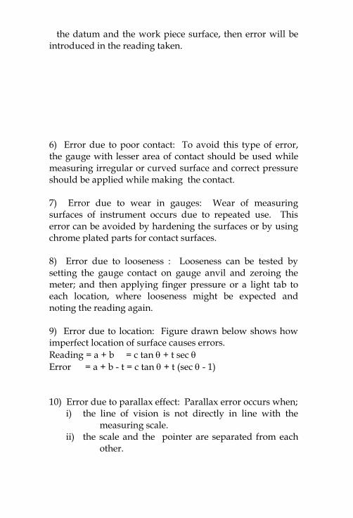
6) Error due to poor contact: To avoid this type of error,the gauge with lesser area of contact should be used whilemeasuring irregular or curved surface and correct pressureshould be applied while making the contact.
7) Error due to wear in gauges: Wear of measuringsurfaces of instrument occurs due to repeated use. Thiserror can be avoided by hardening the surfaces or by usingchrome plated parts for contact surfaces.
8) Error due to looseness : Looseness can be tested bysetting the gauge contact on gauge anvil and zeroing themeter; and then applying finger pressure or a light tab toeach location, where looseness might be expected andnoting the reading again.
9) Error due to location: Figure drawn below shows howimperfect location of surface causes errors.Reading = a + b = c tan + t sec Error = a + b - t = c tan + t (sec - 1)
10) Error due to parallax effect: Parallax error occurs when;i) the line of vision is not directly in line with the
measuring scale.ii) the scale and the pointer are separated from each
other.
In the figure shown below, d = separation of scale andpointer
D = distance between pointer and observer’s eye = angle which the line of sight makes with the
normal to scale
Unit 2Linear & Angular
MeasurementsMeasurement of Engineering Components
Gauges are used mainly to check the EngineeringComponents produced on mass scale, where the job isusually handled by semi-skilled workers. This type ofmeasurement cannot be relied upon where accuracy is moreimportant. The different methods and instruments used forprecision & accurate (linear & angular) measurements arediscussed in this unit.
Comparator
It is a precision instrument employed to compare thedimension of a given component with a working standard(generally slip gauges). It does not measure the actualdimension but indicates how much it differs from the basicdimension (working standard).
Uses of Comparator :
For calibrating the working gauges Used as working gauges Used as final inspection gauges
Essential characteristics of a good Comparator :
Robust design and construction Linear characteristics of scale High magnification Quick in results Versatility Minimum wear of contact point Free from back lash Quick insertion of work piece Provision for compensation from temperature
effects Provision for means to prevent damage during use.
Classification of comparators
1) Mechanical comparatora) Dial indicatorb) Johansson ‘Mikrokator’ comparatorc) Sigma comparatord) Reed type mechanical comparator
2) Optical comparatora) Zeiss Ultra optimeterb) Zeiss optotest comparator
3) Mechanical – Optical comparator4) Electrical comparator5) Fluid displacement comparator6) Pneumatic comparator
a) Back pressure comparatorb) Flow – velocity Pneumatic comparator
In addition, the comparators used in standards roomfor calibration of gauges are :7) Brookes Level comparator8) Eden-Rolt ‘Millionth’ Comparator
Basic principle of operation of comparator
The comparator is first adjusted to zero on its dial orrecording device with a gauge block in position. The gaugeblock (slip gauges) is of dimension which the work piece
should have. The work piece to be checked is then placedin position and the comparator gives the difference indimension in relation to the gauge block. The dimension ofthe work piece may be less than, equal to, or greater thanthe standard dimension. The difference in the dimensionwill be shown in the dial or in the recording device of thecomparator.
Mechanical Comparators: Various mechanical comparatorsare discussed next.
Dial indicator
It is the simplest type of mechanical comparator. It consistsof a base with a rigid column and an arm carrying dialgauge (dial indicator). The arm can be adjusted verticallyup and down along the column. The arm can beswivelled and the dial gauge also can be locked in anyposition along its arm. The whole set up is placed on thesurface place which is used as a datum surface.
Johansson ‘Mikrokator’
A thin metal strip carries at the centre of its length a verylight glass tube pointer. From the centre, the strip ispermanently twisted to form right and left hand helices.One end of the strip is fixed to the adjustable cantileverstrip, the other being anchored to the spring strip elbow,one arm of which is carried on the measuring plunger. Asthe measuring plunger moves, either upwards or downwards, the elbow acts as a bell crank lever and causes thetwisted strip to change its length and thus further twist, oruntwist. Hence, the pointer at the centre of the twisted striprotates an amount proportional to the change in length ofthe strip. It can be shown that the ratio
nW1.9
ionamplificatdd
2
where

l is the length of twisted strip, measured along its neutralaxis.W is the width of twisted stripn is the number of turns is the twist of mid point of strip with respect to end.
The setup is diagrammatically shown below
Johansson ‘Mikrokator’
Sigma comparator
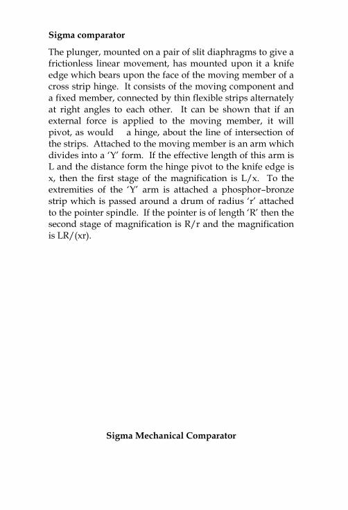
The plunger, mounted on a pair of slit diaphragms to give africtionless linear movement, has mounted upon it a knifeedge which bears upon the face of the moving member of across strip hinge. It consists of the moving component anda fixed member, connected by thin flexible strips alternatelyat right angles to each other. It can be shown that if anexternal force is applied to the moving member, it willpivot, as would a hinge, about the line of intersection ofthe strips. Attached to the moving member is an arm whichdivides into a ‘Y’ form. If the effective length of this arm isL and the distance form the hinge pivot to the knife edge isx, then the first stage of the magnification is L/x. To theextremities of the ‘Y’ arm is attached a phosphor–bronzestrip which is passed around a drum of radius ‘r’ attachedto the pointer spindle. If the pointer is of length ‘R’ then thesecond stage of magnification is R/r and the magnificationis LR/(xr).
Sigma Mechanical Comparator
1
50
Light Source
Condensers
Projection Lens
Mirror
PivotLever
Pivot
Plunger
Screen & Scale
Fig. 2.4 Principle of Optical Comparator
201
The magnification can be adjusted by slackening one andtightening the other screw attaching the knife edge to theplunger and thus adjusting distance ‘x’, while a range ofinstruments of differing magnifications can be produced byhaving drums of different radii ‘r’ and suitable strips.
The other interesting features of this instrument are:a) More safetyb) Dead beat readings can be obtainedc) Fine adjustment is possibled) Parallax error is avoidede) Constant measuring pressure by the use of magnet
plunger.
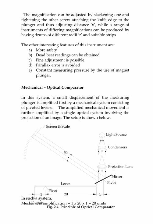
Mechanical – Optical Comparator
In this system, a small displacement of the measuringplunger is amplified first by a mechanical system consistingof pivoted levers. The amplified mechanical movement isfurther amplified by a single optical system involving theprojection of an image. The setup is shown below.
In such a system,Mechanical amplification = 1 x 20 x 1 = 20 units
Optical amplification = 50 x 2 = 100 unitsTotal amplification = 20 x 100 = 2000 units
Pneumatic Comparator
In this system, no physical contact is made either with thesetting gauge or the part being measured, and that internaldimensions may be readily measured, not only with respectto tolerance boundaries, but also geometric form. Further,the system lends itself to the inspection of a single, or anumber of dimensions simultaneously, either during orimmediately after the operating cycle of a machine tool.
Pneumatic Comparator
Back-pressure (Pneumatic) comparator: It uses a watermanometer for the indication of back pressure. It consistsof a vertical metal cylinder filled with water upto a certain
level and a dip tube immersed into it upto a depthcorresponding to the air pressure required. A calibratedmanometer tube is connected between the cylinder andcontrol orifice as shown in fig. 2.5.
The air from its normal source of supply is filtered andpasses through a flow valve. Its pressure is then reducedand maintained at a constant value by a dip tube into awater chamber, the pressure value being determined by thehead of the water displace, excess air escaping toatmosphere. The air at reduced pressure then passesthrough the control orifice, and escapes from the measuringorifice. The back pressure in the circuit is indicated by thehead of water displaced in the manometer tube. The tube isgraduated linearly to show changes of pressure resultingfrom changes in dimension‘d’. Amplifications of up to50000 are obtainable with this system.
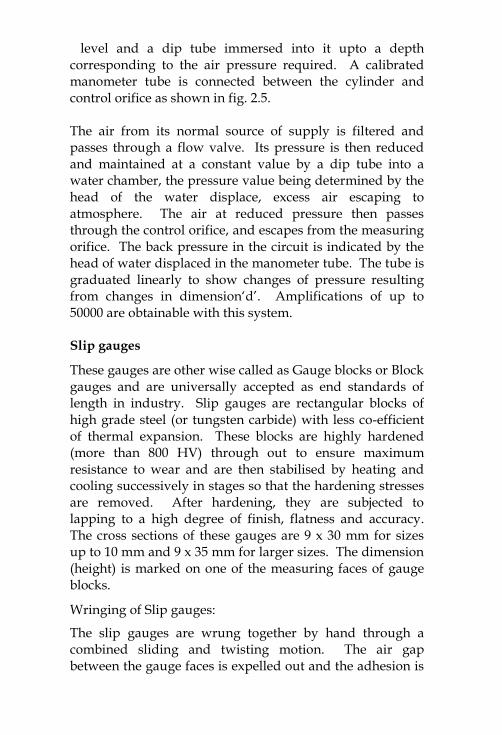
Slip gauges
These gauges are other wise called as Gauge blocks or Blockgauges and are universally accepted as end standards oflength in industry. Slip gauges are rectangular blocks ofhigh grade steel (or tungsten carbide) with less co-efficientof thermal expansion. These blocks are highly hardened(more than 800 HV) through out to ensure maximumresistance to wear and are then stabilised by heating andcooling successively in stages so that the hardening stressesare removed. After hardening, they are subjected tolapping to a high degree of finish, flatness and accuracy.The cross sections of these gauges are 9 x 30 mm for sizesup to 10 mm and 9 x 35 mm for larger sizes. The dimension(height) is marked on one of the measuring faces of gaugeblocks.
Wringing of Slip gauges:
The slip gauges are wrung together by hand through acombined sliding and twisting motion. The air gapbetween the gauge faces is expelled out and the adhesion is

caused partly by molecular attraction and partly byatmospheric pressure. The gap between the two wrung slipgauges is only of the order of 0.00635 m which isnegligible.
When taking the slip gauges apart, the gauges are slid apart.
Procedure for wringing:i) The slip gauges are first cleaned using a lint free cloth orchamois leather or a cleansing tissue.ii) One slip gauge is then placed at 90 to other by usinglight pressure and then it is rotated until the blocks arebrought in one line.
Indian Standards on Slip gauges:Grade II : Workshop grade for rough checks.Grade I : Used for setting up sine bars, checking gapgauges and setting dial test indicators to zero.Grade 0 : Used in tool room and inspection department.Grade 00 : Kept in standard room and used for highprecision work such as checking Grade I and Grade II slipgauges.
Applications of Slip gauges:
Direct precise measurement For calibration of vernier callipers, micrometers, and
other measuring instruments. For setting up a comparator to a specific dimension For angular measurement in conjunction with sine bar For checking gap between parallel locations such as in
gap gauges or between two mating parts.
Selection of Slip gauges for required dimension:
Always start with the last decimal place and deduct thisfrom the required dimension. Select the next smallestfigure in the same way, find the remainder and continuethis until the required dimension is completed. Minimum
number of slip gauges should be selected to build up thegiven dimension.
Roller gauges
Cylindrical rollers with their lengths equal to theirdiameters may be used as gauges, secondary to blockgauges (slip gauges). These are produced to fine tolerances.
Limit gauges
These are inspection tools for rigid design, without a scale,which serve to check the dimensions of manufactured parts.Gauges do not indicate the actual value of the inspecteddimension on the work. They can only be used fordetermining as to whether the inspection parts are madewithin the specified limits. These gauges are made up ofsuitable wear resisting steel and are normally hardened tonot less than 750 HV and suitably stabilised and groundand lapped.
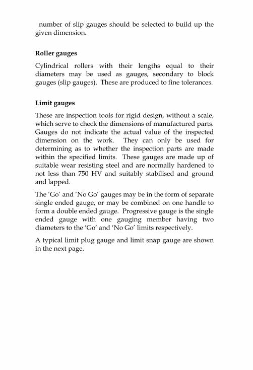
The ‘Go’ and ‘No Go’ gauges may be in the form of separatesingle ended gauge, or may be combined on one handle toform a double ended gauge. Progressive gauge is the singleended gauge with one gauging member having twodiameters to the ‘Go’ and ‘No Go’ limits respectively.
A typical limit plug gauge and limit snap gauge are shownin the next page.

Limit Plug Gauge
Limit Snap Gauge
Gauge Design
Every gauge is a copy of the part which mates with the partfor which the gauge is designed. For example, a bush ismade which is to mate with a shaft; in this case, the shaft isthe mating part. The bush is check by a plug gauge whichin so far as the form of its surface and its size is concerned,is a copy of the mating part (shaft).
Taylor’s principle: According to Taylor, ‘Go’ and ‘No Go’gauges should be designed to check maximum andminimum material limits which are checked as below:‘Go’ limit: This is applied to upper limit of a shaft and lowerlimit of a hole.‘No Go’ limit: This is applied to lower limit of a shaft andthe upper limit of a hole.
Taylor’s principle states that the ‘Go’ gauges should check all thepossible elements of dimensions at a time (roundness, size,location, etc.) and the ‘No Go’ gauge should check onlyone element of the dimension at a time.
Based on Taylor’s principle, ‘Go’ gauge is designed formaximum material condition and ‘No Go’ gauge isdesigned for minimum material condition.
Problem : Design a general type GO and NO GO gauge forcomponents having 20H7f8 fit. Given :(i) i (micron) = 0.45 (D)1/3 + 0.001 D(ii) fundamental deviation of ‘f’ shaft = -5.5 (D)0.41 (D is in
mm)(iii) 20mm falls in the diameter step of 18mm to 30 mm.(iv) IT7 = 16 i(v) IT8 = 25 i
Solution : From the standard table, it is found that 20 liesbetween 18& 30 Hence, D = 21xDD = 30x18 = 23.2379mm
i = 0.45 (D)1/3 + 0.001 D microns= 0.45 (23.2379)1/3 + 0.001 (23.2379)= 1.3074 microns
IT7 = 16 i microns= 16 x 1.3074 microns= 20.918 microns = 0.021 mm
IT8 = 25 i microns= 25 x 1.3074 microns= 33 microns = 0.033 mm
fundamental deviation of shaft = - 5.5 D0.41 microns= - 5.5 x 23.2379 0.41
= - 20 microns = - 0.02 mm
Lower deviation of H - hole = zero
Hence, Limits for hole 20 H7 = 20 + 0.021, + 0.000 mm
Limits for shaft 20 f8 :
Higher Limit of shaft = 20 + fundamental deviation= 20 – 0.02 mm
Lower Limit of shaft = 20 + funda deviation – IT8
= 20 – 0.02 – 0.033= 20 – 0.053 mm
Hence, Limits for shaft 20 f8 = 20 – 0.02, -0.053 mm
Gauge tolerance for plug gauge = 10% of work tolerance(hole)
= 0.1 x 0.021 = 0.0021 mmWear allowance for plug gauge = 10% of gauge tolerance(hole) = 0.1 x 0.0021 = 0.00021 mmGauge tolerance for snap gauge = 10% of work tolerance(shaft) = 0.1 x 0.033 = 0.0033 mmWear allowance on snap gauge = 10% of gauge tolerance(shaft)
= 0.1 x 0.0033= 0.00033 mm
For Hole :
Upper limit of Go plug gauge = 20 + 0.0021 +0.00021
= 20 + 0.00231 mm
Lower limit of Go plug gauge = 20 + 0.00021 mm= 20+ 0.00021 mm
Now, upper limit of No-Go plug gauge = 20.021 + 0.0021 =20.0231 mm
lower limit of No-Go plug gauge = 20.021 mm
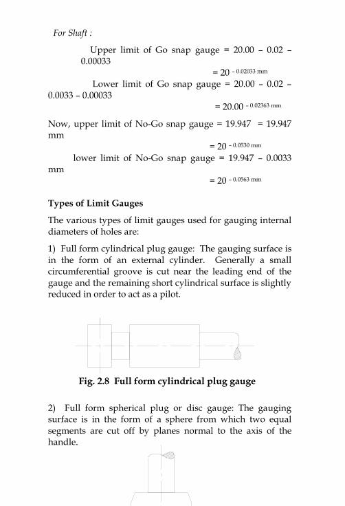
Fig. 2.8 Full form cylindrical plug gauge
Fig. 2.9 Full form spherical plug gauge
For Shaft :
Upper limit of Go snap gauge = 20.00 – 0.02 –0.00033
= 20 – 0.02033 mm
Lower limit of Go snap gauge = 20.00 – 0.02 –0.0033 – 0.00033
= 20.00 – 0.02363 mm
Now, upper limit of No-Go snap gauge = 19.947 = 19.947mm
= 20 – 0.0530 mm
lower limit of No-Go snap gauge = 19.947 – 0.0033mm
= 20 – 0.0563 mm
Types of Limit Gauges
The various types of limit gauges used for gauging internaldiameters of holes are:
1) Full form cylindrical plug gauge: The gauging surface isin the form of an external cylinder. Generally a smallcircumferential groove is cut near the leading end of thegauge and the remaining short cylindrical surface is slightlyreduced in order to act as a pilot.
2) Full form spherical plug or disc gauge: The gaugingsurface is in the form of a sphere from which two equalsegments are cut off by planes normal to the axis of thehandle.
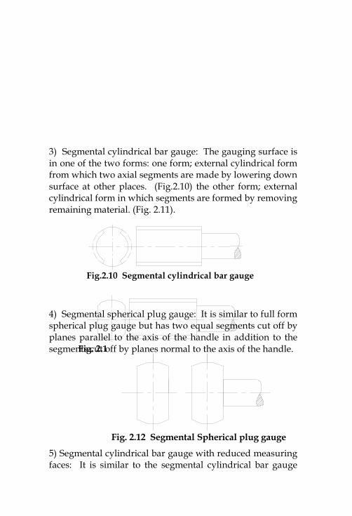
Fig.2.10 Segmental cylindrical bar gauge
Fig. 2.11 Segmental cylindrical bar gauge
Fig. 2.12 Segmental Spherical plug gauge
3) Segmental cylindrical bar gauge: The gauging surface isin one of the two forms: one form; external cylindrical formfrom which two axial segments are made by lowering downsurface at other places. (Fig.2.10) the other form; externalcylindrical form in which segments are formed by removingremaining material. (Fig. 2.11).
4) Segmental spherical plug gauge: It is similar to full formspherical plug gauge but has two equal segments cut off byplanes parallel to the axis of the handle in addition to thesegments cut off by planes normal to the axis of the handle.
5) Segmental cylindrical bar gauge with reduced measuringfaces: It is similar to the segmental cylindrical bar gauge
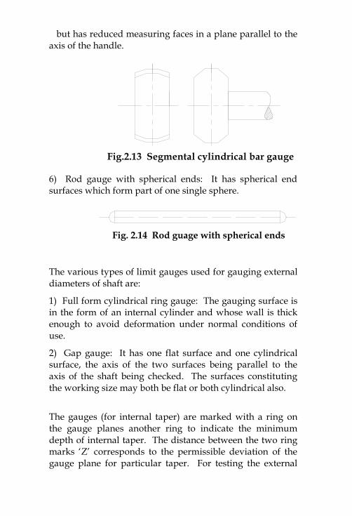
Fig.2.13 Segmental cylindrical bar gauge
Fig. 2.14 Rod guage with spherical ends
but has reduced measuring faces in a plane parallel to theaxis of the handle.
6) Rod gauge with spherical ends: It has spherical endsurfaces which form part of one single sphere.
The various types of limit gauges used for gauging externaldiameters of shaft are:
1) Full form cylindrical ring gauge: The gauging surface isin the form of an internal cylinder and whose wall is thickenough to avoid deformation under normal conditions ofuse.
2) Gap gauge: It has one flat surface and one cylindricalsurface, the axis of the two surfaces being parallel to theaxis of the shaft being checked. The surfaces constitutingthe working size may both be flat or both cylindrical also.
The gauges (for internal taper) are marked with a ring onthe gauge planes another ring to indicate the minimumdepth of internal taper. The distance between the two ringmarks ‘Z’ corresponds to the permissible deviation of thegauge plane for particular taper. For testing the external
taper of the tanged end shank, the ring gauge is inserted, asfar as it goes with light pressure. At the extreme position,no part of the tang under test should extend beyond thesurfaces A, B and C. The shank surfaces may however, lieflush with these surfaces.
The Autocollimator
It is an optical instrument used for the measurement ofsmall angular differences. It is essentially an infinitytelescope and a collimator combined into one instrument.
Principle of Autocollimator:
If a point source of light O is placed at the principal focus ofa collimating lens, it will be projected as a parallel beam oflight as in fig.2.17. If this parallel beam now strikes a planereflector which is normal to the optical axis, it will bereflected back along its own path and refocused at thesource O.If the plane reflector is now tilted through some small angle‘’, the reflected parallel beam will turn through 2, and willbe brought to a focus at O1, in the focal plane, a distance xfrom O. This effect is shown in fig.2.18. If the ray passingthrough the geometric centre of the lens is considered, as itis, unaffected by refraction, it can be seen that x = 2 f mm,where f is the focal length of the lens.
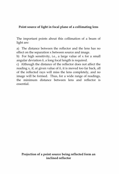
Point source of light in focal plane of a collimating lens
The important points about this collimation of a beam oflight are:
a) The distance between the reflector and the lens has noeffect on the separation x between source and image.b) For high sensitivity, i.e., a large value of x for a smallangular deviation , a long focal length is required.c) Although the distance of the reflector does not affect thereading x, if, at given value of , it is moved too far back, allof the reflected rays will miss the lens completely, and noimage will be formed. Thus, for a wide range of readings,the minimum distance between lens and reflector isessential.
Projection of a point source being reflected form aninclined reflector
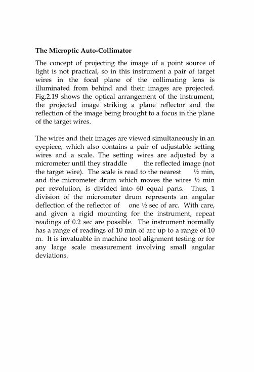
The Microptic Auto-Collimator
The concept of projecting the image of a point source oflight is not practical, so in this instrument a pair of targetwires in the focal plane of the collimating lens isilluminated from behind and their images are projected.Fig.2.19 shows the optical arrangement of the instrument,the projected image striking a plane reflector and thereflection of the image being brought to a focus in the planeof the target wires.
The wires and their images are viewed simultaneously in aneyepiece, which also contains a pair of adjustable settingwires and a scale. The setting wires are adjusted by amicrometer until they straddle the reflected image (notthe target wire). The scale is read to the nearest ½ min,and the micrometer drum which moves the wires ½ minper revolution, is divided into 60 equal parts. Thus, 1division of the micrometer drum represents an angulardeflection of the reflector of one ½ sec of arc. With care,and given a rigid mounting for the instrument, repeatreadings of 0.2 sec are possible. The instrument normallyhas a range of readings of 10 min of arc up to a range of 10m. It is invaluable in machine tool alignment testing or forany large scale measurement involving small angulardeviations.
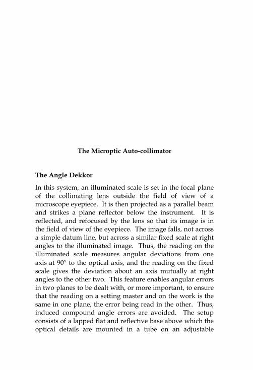
The Microptic Auto-collimator
The Angle Dekkor
In this system, an illuminated scale is set in the focal planeof the collimating lens outside the field of view of amicroscope eyepiece. It is then projected as a parallel beamand strikes a plane reflector below the instrument. It isreflected, and refocused by the lens so that its image is inthe field of view of the eyepiece. The image falls, not acrossa simple datum line, but across a similar fixed scale at rightangles to the illuminated image. Thus, the reading on theilluminated scale measures angular deviations from oneaxis at 90 to the optical axis, and the reading on the fixedscale gives the deviation about an axis mutually at rightangles to the other two. This feature enables angular errorsin two planes to be dealt with, or more important, to ensurethat the reading on a setting master and on the work is thesame in one plane, the error being read in the other. Thus,induced compound angle errors are avoided. The setupconsists of a lapped flat and reflective base above which theoptical details are mounted in a tube on an adjustable
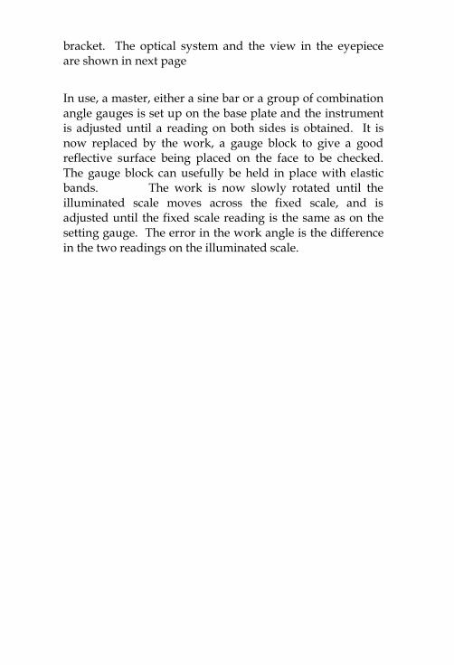
bracket. The optical system and the view in the eyepieceare shown in next page
In use, a master, either a sine bar or a group of combinationangle gauges is set up on the base plate and the instrumentis adjusted until a reading on both sides is obtained. It isnow replaced by the work, a gauge block to give a goodreflective surface being placed on the face to be checked.The gauge block can usefully be held in place with elasticbands. The work is now slowly rotated until theilluminated scale moves across the fixed scale, and isadjusted until the fixed scale reading is the same as on thesetting gauge. The error in the work angle is the differencein the two readings on the illuminated scale.
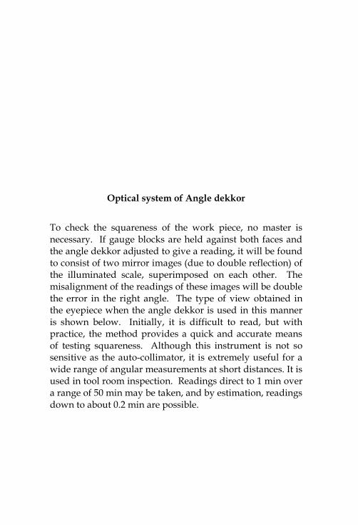
Optical system of Angle dekkor
To check the squareness of the work piece, no master isnecessary. If gauge blocks are held against both faces andthe angle dekkor adjusted to give a reading, it will be foundto consist of two mirror images (due to double reflection) ofthe illuminated scale, superimposed on each other. Themisalignment of the readings of these images will be doublethe error in the right angle. The type of view obtained inthe eyepiece when the angle dekkor is used in this manneris shown below. Initially, it is difficult to read, but withpractice, the method provides a quick and accurate meansof testing squareness. Although this instrument is not sosensitive as the auto-collimator, it is extremely useful for awide range of angular measurements at short distances. It isused in tool room inspection. Readings direct to 1 min overa range of 50 min may be taken, and by estimation, readingsdown to about 0.2 min are possible.
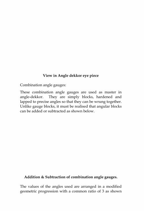
View in Angle dekkor eye piece
Combination angle gauges:
These combination angle gauges are used as master inangle-dekkor. They are simply blocks, hardened andlapped to precise angles so that they can be wrung together.Unlike gauge blocks, it must be realised that angular blockscan be added or subtracted as shown below.
Addition & Subtraction of combination angle gauges.
The values of the angles used are arranged in a modifiedgeometric progression with a common ratio of 3 as shown
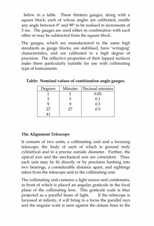
below in a table. These thirteen gauges, along with asquare block, each of whose angles are calibrated, enableany angle between 0 and 90 to be realised in increments of3 sec. The gauges are used either in combination with eachother or may be subtracted from the square block.
The gauges, which are manufactured to the same highstandards as gauge blocks, are stabilised, have ‘wringing’characteristics, and are calibrated to a high degree ofprecision. The reflective properties of their lapped surfacesmake them particularly suitable for use with collimatingtype of instruments.
Table: Nominal values of combination angle gauges.
Degrees Minutes Decimal minutes139
2741
139
27
0.050.10.30.5
The Alignment Telescope
It consists of two units, a collimating unit and a focusingtelescope, the body of each of which is ground trulycylindrical and to a precise outside diameter. Further, theoptical axis and the mechanical axis are coincident. Thus,each unit may be fit directly or by precision bushing intotwo bearings, a considerable distance apart, and sightingstaken from the telescope unit to the collimating unit.
The collimating unit contains a light source and condensers,in front of which is placed an angular graticule in the focalplane of the collimating lens. This graticule scale is thusprojected as a parallel beam of light. If the telescope isfocussed at infinity, it will bring to a focus the parallel raysand the angular scale is seen against the datum lines in the
telescope. Thus, angular misalignment in both planes isdetermined. The collimating unit also contains, in front ofthe collimating lens, a second graticule also havingtwo scales at right angles to each other. If the focus of thetelescope is now shortened, this graticule is seen against thedatum lines of the telescope and linear displacements aremeasured directly. In this case, the collimating lens issimply providing even illumination for the displacementgraticule, and the angular misalignment graticule cannot beseen because it is so far out of focus. A line diagram of thecollimating unit and the view in the telescope eyepiece atboth conditions of focus is shown in fig. 2.23.
The Alignment Telescope
Workpiecel
h
Surface Plate
Dial Gauge
Slip Gauges
h
Fig. 2.24 Sine bar
It should be noted that distance has no effect on theangular misalignment readings, as these are taken using thecollimating principle. However, this is not so with thelinear displacement scale. The telescope only magnifies theapparent size of the scale as seen by the eye. Thus, as thedistance is increased, the size of the displacement scale isreduced and its ‘readability’ is also reduced. Thus, theaccuracy of this reading diminishes with distance.
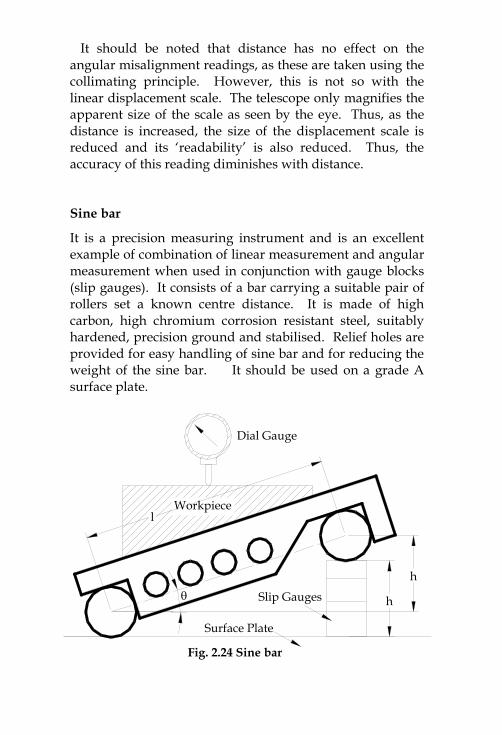
Sine bar
It is a precision measuring instrument and is an excellentexample of combination of linear measurement and angularmeasurement when used in conjunction with gauge blocks(slip gauges). It consists of a bar carrying a suitable pair ofrollers set a known centre distance. It is made of highcarbon, high chromium corrosion resistant steel, suitablyhardened, precision ground and stabilised. Relief holes areprovided for easy handling of sine bar and for reducing theweight of the sine bar. It should be used on a grade Asurface plate.
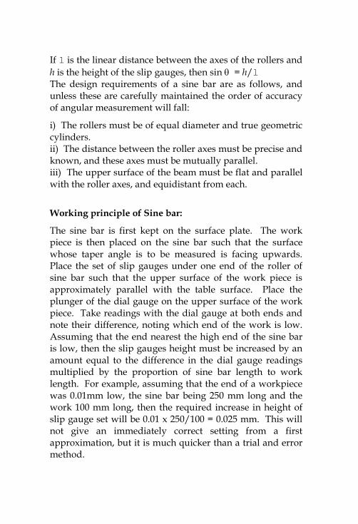
If l is the linear distance between the axes of the rollers andh is the height of the slip gauges, then sin = h/lThe design requirements of a sine bar are as follows, andunless these are carefully maintained the order of accuracyof angular measurement will fall:
i) The rollers must be of equal diameter and true geometriccylinders.ii) The distance between the roller axes must be precise andknown, and these axes must be mutually parallel.iii) The upper surface of the beam must be flat and parallelwith the roller axes, and equidistant from each.
Working principle of Sine bar:
The sine bar is first kept on the surface plate. The workpiece is then placed on the sine bar such that the surfacewhose taper angle is to be measured is facing upwards.Place the set of slip gauges under one end of the roller ofsine bar such that the upper surface of the work piece isapproximately parallel with the table surface. Place theplunger of the dial gauge on the upper surface of the workpiece. Take readings with the dial gauge at both ends andnote their difference, noting which end of the work is low.Assuming that the end nearest the high end of the sine baris low, then the slip gauges height must be increased by anamount equal to the difference in the dial gauge readingsmultiplied by the proportion of sine bar length to worklength. For example, assuming that the end of a workpiecewas 0.01mm low, the sine bar being 250 mm long and thework 100 mm long, then the required increase in height ofslip gauge set will be 0.01 x 250/100 = 0.025 mm. This willnot give an immediately correct setting from a firstapproximation, but it is much quicker than a trial and errormethod.
Component
VernierHeight Gauge
Reading R1Reading R2
Dial TestIndicator aFiducialIndicator
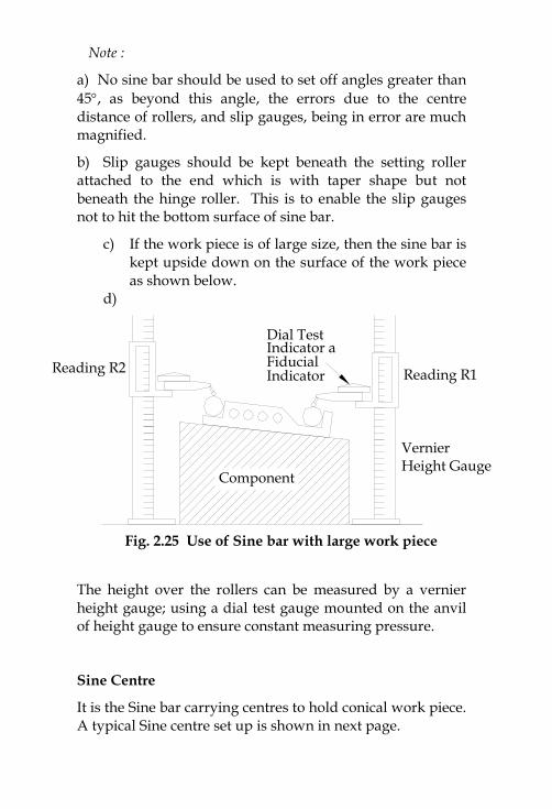
Fig. 2.25 Use of Sine bar with large work piece
Note :
a) No sine bar should be used to set off angles greater than45, as beyond this angle, the errors due to the centredistance of rollers, and slip gauges, being in error are muchmagnified.
b) Slip gauges should be kept beneath the setting rollerattached to the end which is with taper shape but notbeneath the hinge roller. This is to enable the slip gaugesnot to hit the bottom surface of sine bar.
c) If the work piece is of large size, then the sine bar iskept upside down on the surface of the work pieceas shown below.
d)
The height over the rollers can be measured by a vernierheight gauge; using a dial test gauge mounted on the anvilof height gauge to ensure constant measuring pressure.
Sine Centre
It is the Sine bar carrying centres to hold conical work piece.A typical Sine centre set up is shown in next page.
RollerPivot Slip Gauges
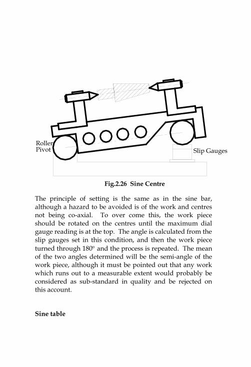
Fig.2.26 Sine Centre
The principle of setting is the same as in the sine bar,although a hazard to be avoided is of the work and centresnot being co-axial. To over come this, the work pieceshould be rotated on the centres until the maximum dialgauge reading is at the top. The angle is calculated from theslip gauges set in this condition, and then the work pieceturned through 180 and the process is repeated. The meanof the two angles determined will be the semi-angle of thework piece, although it must be pointed out that any workwhich runs out to a measurable extent would probably beconsidered as sub-standard in quality and be rejected onthis account.
Sine table
It is the most convenient and accurate design for heavywork piece. The equipment consists of a self containedsine bar hinged at one roller and mounted on its datumsurface. The table is quite rigid one and the weight of unitand work piece is given fuller and safer support. The sinebar may be safely swung to any angle from 0 to 90 bypivoting it about its hinged end.
Bevel Protractor
It is the simplest angle measuring instrument. A simplevernier bevel protractor with its various elements is shownin fig.2.27.
Vernier Bevel Protractor
The body of the bevel protractor is designed in such a waythat its back is flat and there are no projections beyond itsback. The base plate is attached to the main body and anadjustable blade is attached to a circular plate containingvernier scale. The main body carries a main scalegraduated in degrees. The adjustable blade which iscapable of rotating freely about the centre of the main scale
engraved on the body of the instrument can be locked inany position. An acute angle attachment is provided at thetop. The base of the base plate is made flat so that it couldbe laid flat upon the work piece. The blade can be movedalong throughout its length and can also be reversed. Theacute angle attachment can be readily fit into the body andclamped in any position.
Universal Bevel protractor: The protractor dial is slotted tohold a blade which can be rotated with the dial to therequired angle. It can also be adjusted independently toany desired length. The blade can be locked in any position.This instrument is capable of readings precisely within 5minutes.
Optical Bevel protractor: This instrument is capable oftaking readings within 2 minutes of an arc. The intervalcircular scale is graduated in divisions of 10 minutes of arc.Readings are taken with the help of optical magnifyingsystem which is an integral part of the instrument.
Uses of Bevel protractor:The bevel protractors can be used to test the flatness,squareness, parallelism, straightness, angularmeasurements, etc.
Types of bevel protractors:
As per IS practice, there are two bevel protractors, namely;1) Mechanical Bevel protractor
a) with vernier and acute angle attachmentb) without vernier and acute angle attachment
2) Optical Bevel protractor