engineering of polymers to thicken carbon...
TRANSCRIPT

ENGINEERING OF POLYMERS TO THICKEN CARBON DIOXIDE:
A SYSTEMATIC APPROACH
by
Sevgi Kilic
BS, Chemical Engineering, Hacettepe University, 1994
MS, Chemical Engineering, The Pennsylvania State University, 1998
Submitted to the Graduate Faculty of
the School of Engineering in partial fulfillment
of the requirements for the degree of
Doctor of Philosophy
University of Pittsburgh
2003

ii
UNIVERSITY OF PITTSBURGH
SCHOOL OF ENGINEERING
This dissertation was presented
by
Sevgi Kilic
It was defended on
October 9, 2003
and approved by
Robert M. Enick, Professor, Chemical and Petroleum Engineering Department
J. Karl Johnson, Associate Professor, Chemical and Petroleum Engineering Department
Toby Chapman, Associate Professor, Department of Chemistry
Dissertation Director: Eric J. Beckman, Chairman and Professor, Chemical and Petroleum Engineering Department

iii
ENGINEERING OF POLYMERS TO THICKEN CARBON DIOXIDE:
A SYSTEMATIC APPROACH
Sevgi Kilic, Ph.D.
University of Pittsburgh, 2003
Carbon dioxide (CO2) is one of the potential displacing fluids used in Enhanced Oil
Recovery (EOR). However, the effective use of CO2 in EOR is hindered by its low viscosity,
resulting in CO2 to “finger” towards production well and thus low sweep efficiency. The current
research has aimed to bring the viscosity of CO2 to a level comparable to that of oil via
dissolution of polymeric materials (thickeners) to suppress early breakthrough of CO2 in EOR. A
series of fluoroacrylate-aromatic acrylate copolymers was designed and tested for their
miscibility and viscosity enhancement in CO2 at 295 K. The change in the series was created by
changing either the spacer length or the size of aromatic rings in the aromatic acrylate unit of the
copolymer. Aforementioned copolymers were found to be highly miscible with CO2 and to
impart enhancement in the viscosity of CO2, depending on the type and content of the aromatic
acrylate unit in the copolymer. Increase in the viscosity was attributed to association of aromatic
rings by stacking.

iv
Feasibility of EOR process depends also on the factors associated with economic and
environmental issues. The current research, therefore, also aimed to explore the generation of
low-cost, non-fluorous polymers to replace high cost fluoroacrylate moiety. The polymers were
designed hypothesizing that a CO2-philic polymer should posses inherently low cohesive energy
density, low glass transition temperature (i.e. high chain flexibility and free vo lume) and a
number of Lewis base groups to promote cross interactions with CO2. Polymers were prepared,
where possible, via modification of an existing polymer with a precursor containing Lewis base
group to eliminate the effect of chain length on the phase behavior. Modifications were
performed basically on silicone, polyether or hydrocarbon backbone (vinyl and allyl). The phase
behavior results showed that there is a delicate balance between the forces working to increase
the miscibility pressures (e.g. high cohesive energy density) or factors suppressing the entropy of
mixing, and those working to lower miscibility pressures, such as enhanced specific interactions
with CO2 and increased free volume or chain flexibility.

v
TABLE OF CONTENTS ACKNOWLEDGMENTS ............................................................................................................xvi
1.0 INTRODUCTION .............................................................................................................. 1
1.1 CARBON DIOXIDE AS A FLOODING AGENT IN ENHANCED OIL RECOVERY.. 1
2.0 BACKGROUND ................................................................................................................ 5
2.1 PREVIOUS ATTEMPTS TO DECREASE THE MOBILITY OF CO2 ............................ 5
2.2 MILESTONES IN THE DEVELOPMENT OF CO2-PHILIC MATERIALS ................. 10
3.0 RESEARCH OBJECTIVE AND APPROACH ............................................................... 15
3.1 RESEARCH OBJECTIVE ............................................................................................... 15
3.2 RESEARCH APPROACH FOR CO2-THICKENERS .................................................... 17
3.2.1 Stacking of Aromatic Rings:........................................................................................ 17
3.2.2 Design Strategy for CO2-Direct Thickeners: ............................................................... 20
3.3 RESEARCH APPROACH FOR CO2-PHILIC POLYMERS .......................................... 22
3.3.1 Heuristics on Miscibility of Materials with CO2: ........................................................ 22
3.3.2 Design Strategy for CO2-Philic Polymers: .................................................................. 28
4.0 ACRYLATE COPOLYMERS AS CO2-DIRECT THICKENERS.................................. 30
4.1 EXPERIMENTAL PROTOCOL...................................................................................... 30
4.1.1 Materials: .................................................................................................................... 30
4.1.2 Synthesis of Copolymers of Styrene with Fluoroacrylate and its Sulfonation: .......... 31
4.1.3 Synthesis of Aromatic Acrylate Monomers:............................................................... 32

vi
4.1.4 Synthesis of Copolymers of Aromatic Acrylates with Fluoroacrylate:...................... 34
4.1.5 Synthesis of Copolymers of Cyclohexyl Acrylate with Fluoroacrylate: .................... 35
4.1.6 Structural Characterization: ........................................................................................ 35
4.1.7 Phase Behavior Measurements: .................................................................................. 38
4.1.8 Solution Relative Viscosity Measurements: ................................................................ 40
4.2 PHASE BEHAVIOR RESULTS OF COPOLYMERS IN DENSE CO2 ......................... 44
4.3 VISCOSITY BEHAVIOR RESULTS OF COPOLYMERS IN DENSE CO2................. 54
4.4 CONCLUSIONS.............................................................................................................. 70
5.0 EFFECT OF GRAFTED LEWIS BASE GROUPS ON THE PHASE BEHAVIOR OF
MODEL POLY (DIMETHYL SILOXANES) IN CO2 ................................................................ 73
5.1 INTRODUCTION ............................................................................................................ 73
5.2 EXPERIMENTAL PROTOCOL...................................................................................... 74
5.2.1 Materials: ..................................................................................................................... 74
5.2.2 Synthesis of Lewis Base Grafted Siloxane Polymers:................................................. 75
5.2.3 Structural Characterization: ......................................................................................... 76
5.2.4 Phase Behavior Measurements: ................................................................................... 77
5.3 PHASE BEHAVIOR RESULTS OF LEWIS BASE GRAFTED SILOXANE
POLYMERS ............................................................................................................................. 79
5.4 CONCLUSIONS............................................................................................................... 95
6.0 EVALUATION OF PHASE BEHAVIOR OF NITROGEN CONTAINING POLYMERS
IN CO2........................................................................................................................................... 97
6.1 INTRODUCTION ............................................................................................................ 97
6.2 EXPERIMENTAL PROTOCOL...................................................................................... 98

vii
6.2.1 Materials: ..................................................................................................................... 98
6.2.2 Polymerization of N,N-dimethylacrylamide:............................................................... 98
6.2.3 Synthesis of Poly(propylethyleneimine):..................................................................... 99
6.2.4 Preparation of Poly(propylmethylacrylate ethyleneimines): ..................................... 101
6.2.5 Phase Behavior Measurements: ................................................................................. 101
6.3 PHASE BEHAVIOR RESULTS OF NITROGEN CONTAINING POLYMERS ........ 102
7.0 EFFECT OF BACKBONE TYPE AND ETHER OXYGEN ON PHASE BEHAVIOR
OF POLYMERS IN CO2 ............................................................................................................ 108
7.1 INTRODUCTION .......................................................................................................... 108
7.2 EXPERIMENTAL PROTOCOL.................................................................................... 109
7.2.1 Materials: ................................................................................................................... 109
7.2.2 Synthesis of Poly(allyl alcohol) via Reduction:......................................................... 109
7.2.3 Synthesis of Poly(allyl acetate):................................................................................. 111
7.2.4 Synthesis of Partially Sulfinate-functionalized Poly(propylene glycol):................... 111
7.2.5 Synthesis of Poly(propylene oxide)-dimethyl ether: ................................................. 113
7.2.6 Phase Behavior Measurements: ................................................................................. 115
7.3 PHASE BEHAVIOR RESULTS OF THE POLYMERS IN CO2.................................. 115
7.4 CONCLUSIONS............................................................................................................. 130
8.0 SUMMARY.................................................................................................................... 131
9.0 FUTURE WORK............................................................................................................ 134
A 1H-NMR SPECTRA OF COPOLYMERS IN CHAPTER 4 .............................................. 143
B 1H-NMR AND FT-IR SPECTRA OF SILICONE POLYMERS (CHAPTER 5) .............. 146
C 1H-NMR SPECTRA OF NITROGEN CONTAINING POLYMERS (CHAPTER 6) ...... 150

viii
D 1H-NMR SPECTRA OF THE POLYMERS IN CHAPTER 7........................................... 154
BIBLIOGRAPHY....................................................................................................................... 157

ix
LIST OF TABLES
Table 4.1 General Structure of the Fluoroacrylate-Aromatic Acrylate copolymers..................... 37 Table 4.2 Number of “m” and “n” in the aromatic acrylates used in this study. .......................... 46 Table 5.1 Methylhydrosiloxane-dimethylsiloxane copolymers(a) used in this study.................... 74 Table 6.1 Structure of Polymers Possessing Nitrogen................................................................ 106 Table 7.1 Surface tension and glass transition temperature of the polymers used to assess ...... 122

x
LIST OF FIGURES
Figure 1.1 Change of viscosity of CO2 with temperature at different pressures. ........................... 3 Figure 1.2 CO2 Flooding in EOR: (a) Ideal case, (b) Actual behavior. .......................................... 4 Figure 3.1 Packing of molecules in crystalline benzene, showing: a. a stereoview of the overall
structure; b. the shortest C…H distances in Ao (representative of an H…π interactions.................................................................................................................................... 19
Figure 3.2 Structure of fluoroacrylate monomer .......................................................................... 20 Figure 3.3 General Structure of Aromatic Acrylate-Fluoroacrylate Copolymers ........................ 22 Figure 4.1 Phase Behavior of Sulfonated and Unsulfonated Styrene-Fluoroacrylate Copolymer in
CO2 at T=295 K (St: Styrene, FA: Fluoroacrylate, S.St: Sulfonated Styrene) 1) 11%St-89%FA, 2) 0.1%S.St -10.9%St-89%FA ........................................................ 45
Figure 4.2 Phase Behavior of PHA-FA Copolymer in CO2 at T=295 K (PHA: Phenyl Acrylate,
n=0, m=1; FA: Fluoroacrylate) 1) 31%PHA-69%FA, 2) 29%PHA-71%FA, 3) 26%PHA-74%FA, 4) 23%PHA-77%FA. .................................................................. 47
Figure 4.3 Phase Behavior of BEA-FA Copolymer in CO2 at T=295 K (BEA: Benzyl Acrylate,
n=1, m=1; FA: Fluoroacrylate), 1) 54%BEA-46%FA, 2) 38%BEA-62%FA, 3) 27%BEA-73%FA, 4) 29%BEA-71%FA, 5) 18%BEA-82%FA, 6) 21%BEA-79%FA.................................................................................................................................... 48
Figure 4.4 Phase Behavior of PEA-FA Copolymer in CO2 at T=295 K (PEA: Phenyl ethyl
acrylate, n=2, m=1; FA: Fluoroacrylate),1) 36%PEA-64%FA, 2) 24%PEA-76%FA, 3) 26%PEA-74%FA, 4) 25%PEA-75%FA, 5) 29%PEA-71%FA............................. 49
Figure 4.5 Effect of spacer length on the phase behavior of copolymers in CO2 at T=295 K
(PHA: Phenyl acrylate, n=0, m=1; BEA: Benzyl acrylate, n=1, m=1; PEA: Phenyl ethyl acrylate, n=2, m=1; FA: Fluoroacrylate), 1) 29%PHA-71%FA, 2) 29%BEA-71%FA, 3) 29%PEA-71%FA. ................................................................................... 50

xi
Figure 4.6 Phase Behavior of NA-FA Copolymer in CO2 at T=295 K (NA: Naphthyl acrylate, n=0, m=2; FA: Fluoroacrylate), 1) 32%NA-68%FA, 2) 17%NA-83%FA, 3) 22%NA-78%FA, 4) 19%NA-81%FA ...................................................................................... 51
Figure 4.7 Phase Behavior of NA-FA and PHA-FA Copolymers in CO2 at T=295 K (NA:
Naphthyl acrylate; n=0, m=2; PHA: Phenyl acrylate, n=0, m=1, FA: Fluoroacrylate), 1) 32%NA-68%FA, 2) 31%PHA-69%FA, 3) 22%NA-78%FA, 4) 23%PHA-77%FA.................................................................................................................................... 52
Figure 4.8 Phase Behavior of NA-FA, CHA-FA and PHA-FA Copolymers in CO2 at T=295 K
(CHA: Cyclohexyl acrylate, NA: Naphthyl acrylate; n=0, m=2; PHA: Phenyl acrylate, n=0, m=1, FA: Fluoroacrylate), 1) 22%NA-88%FA, 2) 22%CHA-78%FA, 3) 23%PHA-77%FA .................................................................................................. 53
Figure 4.9 Relative viscosity of Sulfonated and Unsulfonated Styrene-Fluoroacrylate Copolymer
Solutions in CO2 as a function of concentration at T=295 K and P=41.4 MPa (St: Styrene, FA: Fluoroacrylate, S.St: Sulfonated Styrene), 1) 0.1%S.St-10.9%St-89%FA, 2) 11%St-89%FA......................................................................................... 55
Figure 4.10 Relative viscosity of x%PHA-y%FA copolymer solutions in CO2 as a function of
concentration at T=295 K at varying copolymer composition, P=41.4 MPa, (PHA: Phenyl Acrylate, n=0, m=1; FA: Fluoroacrylate), 1) 29%PHA-71%FA, 2) 26%PHA-74%FA, 3) 23%PHA-77%FA, 4) 31%PHA-69%FA................................................. 56
Figure 4.11 Relative viscosity of x%BEA-y%FA copolymer solutions in CO2 as a function of
concentration at T=295 K at varying copolymer composition, P=41.4 MPa, (BEA: Benzyl Acrylate, n=1, m=1; FA: Fluoroacrylate), 1) 18%BEA-82%FA, 2) 21%BEA-79%FA, 3) 27%BEA-73%FA, 4) 29%BEA-71%FA, 5) 38%BEA-62%FA, 6) 54%BEA-46%FA....................................................................................................... 57
Figure 4.12 Relative viscosity of x%PEA-y%FA copolymer solutions in CO2 as a function of
concentration at T=295 K at varying copolymer composition, P=41.4 MPa, (PEA: Phenyl ethyl acrylate, n=2, m=1; FA: Fluoroacrylate), 1) 24%PEA-76%FA, 2) 36%PEA-64%FA, 3) 25%PEA-75%FA, 4) 26%PEA-74%FA, 5) 29%PEA-71%FA.................................................................................................................................... 58
Figure 4.13 Effect of spacer length on CO2-viscosity enhancement of copolymer solutions as a
function of concentration at T=295 K and P= 41.4 MPa, (BEA: Benzyl Acrylate, n=1, m=1; PHA: Phenyl acrylate, n=0, m=1; PEA: Phenyl ethyl acrylate, n=2, m=1; FA: Fluoroacrylate), 1) 29%PHA-71%FA, 2) 29%PEA-71%FA, 3) 29%BEA-71%FA ....................................................................................................................... 60
Figure 4.14 The effect of pressure on relative viscosity of 29%PHA-71%FA copolymer solutions
in CO2 as a function of concentration at T=295 K (PHA: Phenyl Acrylate, n=0, m=1; FA: Fluoroacrylate), 1) P=41.4 MPa, 2) P=34.5 MPa, 3) P=27.6 MPa, 4) P=20.7 MPa. ........................................................................................................................... 62

xii
Figure 4.15 Comparison of aromatic and non-aromatic rings on CO2-viscosity enhancement at similar compositions at T=295 K and P=41.4 MPa as a function of concentration (PHA: Phenyl Acrylate; CHA: Cyclohexyl Acrylate; FA: Fluoroacrylate), 1) 26%PHA-74%FA, 2) 27%CHA-73%FA. .................................................................. 63
Figure 4.16 Comparison of aromatic and non-aromatic rings on CO2-viscosity enhancement at
their optimum composition at T=295 K and P=41.4 MPa as a function of concentration (PHA: Phenyl Acrylate; CHA: Cyclohexyl Acrylate; FA: Fluoroacrylate), 1) 29%PHA-71%FA, 2) 16%CHA-84%FA. ................................... 64
Figure 4.17 Comparison of effect of size of aromatic rings on viscosity enhancement ability of
CO2 at similar compositions at T=295 K and P=41.4 MPa as a function of concentration (PHA: Phenyl acrylate; NA: Naphthyl acrylate; FA: Fluoroacrylate), 1) 23%PHA-77%FA, 2) 22%NA-78%FA. ..................................................................... 65
Figure 4.18 Comparison of effect of size of aromatic rings on viscosity enhancement ability of
CO2 at their optimum compositions at T=295 K and P= 41.4 MPa as a function of concentration (PHA: Phenyl acrylate; NA: Naphthyl acrylate; FA: Fluoroacrylate), 1) 29%PHA-71%FA, 2) 32%NA-68%FA. ..................................................................... 66
Figure 4.19 Relative viscosity of x%NA-y%FA copolymer solutions in CO2 as a function of
concentration at T=295 K at varying copolymer composition, and P=41.4 MPa, (NA: Naphthyl Acrylate, n=0, m=2; FA: Fluoroacrylate), 1) 32%NA-68%FA, 2) 19%NA-81%FA, 3) 17%NA-83%FA, 4) 22%NA-78%FA..................................................... 69
Figure 4.20 The effect of pressure on relative viscosity of 32%NA-68%FA copolymer solutions
in CO2 as a function of concentration at T=295 K (NA: Naphthyl Acrylate, n=0, m=2; FA: Fluoroacrylate), 1) 41.4 MPa, 2) 34.5 MPa, 3) 27.6 MPa, 4) 20.7 MPa. .. 70
Figure 5.1 Phase behavior of functionalized (z=5) siloxane copolymers, 1) methyl butyrate
(MB), 2) propyl acetate (PA), at 295 K...................................................................... 81 Figure 5.2 Phase behavior of functionalized (z=5) siloxane copolymers 1) butyl methyl ketone
(BMK), 2) propyl acetate (PA), at 295 K................................................................... 82 Figure 5.3 CO2-carbonyl interactions having a) C2ν b) Cs symmetry........................................... 84 Figure 5.4 Phase behaviors of functionalized (z=5) siloxane copolymers, 1) propyl methyl
carbonate (PMC), 2) propyl acetate (PA) at 295 K.................................................... 86 Figure 5.5 Comparison of phase behaviors of hydromethyl-dimethyl siloxane copolymers at
varying functionality with a total of 25 repeat units, at 295 K, 1) z=2, 2) z=0, 3) z=1..................................................................................................................................... 87
Figure 5.6 Phase behavior of propyl acetate (PA)-functionalized siloxane copolymers at different
degree of substitution 1) z=11, 2) z=1, 3) z=2, 4) z=5, at 295 K. .............................. 88

xiii
Figure 5.7 Phase behaviors of methyl butyrate (MB)-functionalized siloxane copolymers at different degree of substitution 1) z=11, 2) z=2, 3) z=5, 4) z=1, at 295 K. ............... 89
Figure 5.8 Phase behavior of propyl ethyl ether- functionalized siloxane copolymers at different
degree of substitution 1) z=11, 2) z=5, 3) z=1, 4) z=2, at 295 K. .............................. 89 Figure 5.9 Phase behaviors of (z=2) functional siloxane copolymers with 1) Propyl acetate (PA),
2) Butyl methyl ketone (BMK), 3) Propyl ethyl ether (PEE) at 295 K...................... 92 Figure 5.10 Phase behaviors of (z=5) functional siloxane copolymers with 1) Propyl ethyl ether
(PEE), 2) Butyl methyl ketone (BMK), 3) Propyl acetate (PA), at 295 K................. 93 Figure 5.11 Comparison of phase behaviors of 1) (z=1) propyl dimethyl amine-functional
(PDA), 2) (z=5) propyl acetate (PA)-functional siloxane copolymers at 295 K. ...... 94 Figure 7.1 Schematic for reduced and functionalized poly(epichlorohydrin) (PECH) .............. 117 Figure 7.2 Schematic for hypothesized steric hindrance in ether- functionalized PPO’s (repulsive
effects indicated by arrows) ..................................................................................... 118 Figure 7.3 Structure of poly(allyl acetate) .................................................................................. 119 Figure 7.4 Phase behavior of 1) PP-425,124 2) Poly(propylene glycol)-monomethylether,
Mw=1000, at 295 K. ................................................................................................ 123 Figure 7.5 Effect of location of oxygen (backbone versus side chain) in the polymer on phase
behavior: 1) PPO-DME 3500, 2) PVME -3850 at 295 K. ....................................... 124 Figure 7.6 Effect of length of side chain on phase behavior in vinyl ether polymers, 1) PVME
3850, 2) PVEE-3800,124 at 295 K ............................................................................ 126 Figure 7.7 Phase behavior of (1) PPO-DME 3500 (2) PVEE 3800124 at 295 K......................... 127 Figure 7.8 Comparison of phase behavior of 1) PVAc-7700,56 2) PVEE-3800,124 3) PVAc-
3090,56 at 295 K........................................................................................................ 129 Figure 9.1 (a) Poly(vinyl acetate-co-aromatic acrylate), (b) Poly(vinyl acetate-co-aromatic
acetate) ..................................................................................................................... 135 Figure 9.2 Structure of poly(isobutylene oxide) ......................................................................... 136 Figure 9.3 Structure of (a) poly(vinyl acetate-co-vinyl ethyl ether), (b) poly(vinyl acetate-co-
isobutylene oxide). ................................................................................................... 137 Figure 9.4 Structure of Poly(vinyl sulfonate) ............................................................................. 138

xiv
Figure 9.5 Structure of (a) Poly(vinyl sulfonate-co-vinyl ethyl ether), (b) Poly(vinyl sulfonate-co-isobutylene oxide). .............................................................................................. 138
Figure 9.6 Poly(vinyl ethyl ketone) ............................................................................................ 139 Figure 9.7 Reaction scheme for synthesis of substitued poly(oxetane)s. ................................... 140 Figure 9.8 Structure of Poly(oxetane)......................................................................................... 140 Figure 9.9 Poly(methylated ethyleneimine-co-acetylated ethyleneimine) ................................. 141 Figure A.1 1H-NMR spectrum of St-FA Copolymer in Freon. ................................................. 143 Figure A.2 1H-NMR spectrum of 29%PHA-71% Copolymer in Freon.................................... 143 Figure A.3 1H-NMR spectrum of 21%BEA-79%FA Copolymer in Freon............................... 144 Figure A.4 1H-NMR spectrum of 29%PEA-71%FA Copolymer in Freon ............................... 144 Figure A.5 1H-NMR spectrum of 17%NA-83%FA Copolymer in Freon................................. 145 Figure A.6 1H-NMR spectrum of 27%CHA-73%FA Copolymer in Freon............................... 145 Figure B.1 FT-IR spectrum for a) methylhydrosiloxane (16.5mole %)-dimethylsiloxane
(83.5mole%) copolymer, b) Propyl acetate functionalized siloxane copolymer. The peak at 2157 cm-1 in Figure 1.a corresponds to Si-H stretching. ............................. 146
Figure B.2 1H NMR spectrum (300 MHz, CDCl3) of a) MethylHydrosiloxane (16.5mole %) -
Dimethylsiloxane (83.5mole%) copolymer, The peak at 4.7 ppm corresponds to Si-H. b) (z=5) PA-functionalized siloxane copolymer ................................................. 147
Figure B.3 1H-NMR spectrum of (z=5) MB-functional siloxane copolymer in CDCl3 ............ 148 Figure B.4 1H-NMR spectrum of (z=5) PMC-functional siloxane copolymer in CDCl3 .......... 148 Figure B.5 1H-NMR spectrum of (z=5) PDA-functional siloxane copolymer in CDCl3 .......... 149 Figure C.1 1H-NMR Spectrum of Poly(N,N-dimethyl acrylamide) in C6D6............................. 150 Figure C.2 FT-IR spectrum of Poly(2-ethyl-2-oxazoline), Mw=5000 (Scientific Polymers, Inc.)
.................................................................................................................................. 151 Figure C.3 FT-IR spectrum of Poly(propylethyleneimine) ....................................................... 151 Figure C.4 1H-NMR spectrum of Poly(2-ethyl-2-oxazoline), Mw=5000 (SP2 Inc.)................. 152

xv
Figure C.5 1H-NMR spectrum of Poly(propylethyleneimine) in CDCl3 ................................... 152 Figure C.6 1H-NMR spectrum of PPMAEI in CDCl3 ............................................................... 153 Figure D.1 1H-NMR spectrum of poly(allyl alcohol) in D2O.................................................... 154 Figure D.2 1H-NMR spectrum of poly(allyl acetate) in C6D6 ................................................... 154 Figure D.3 FT-IR spectrum of poly(propylene glycol), Mw=3500 (Aldrich) ........................... 155 Figure D.4 FT-IR spectrum of poly(propylene oxide) dimethylether ....................................... 155 Figure D.5 1H-NMR (CDCl3) spectrum of poly(propylene glycol), Mw=3500 ........................ 156 Figure D.6 1H-NMR (CDCl3) spectrum of poly(propylene oxide) dimethylether .................... 156
xvi
ACKNOWLEDGMENTS
It is a great pleasure that I have now the opportunity to express my gratitude to the people
who contributed their efforts in accomplishment of this work. First, I would like to thank Dr.
Eric Beckman, my Ph.D. advisor, for his valuable suggestions, creative discussions and
encouragement during the course of this study. I appreciate his efforts to teach his students to see
the “big picture” and his respect to other’s ideas.
Special thanks to all my friends for their moral support and the fun times we shared
together. I also would like to thank Yang Wang for the ab initio calculation results. Many thanks
are also in order for the staff of the chemical engineering department for their behind-the-scenes
work.
I would like to thank the committee members, Dr. R. Enick, Dr. K. Johnson, and Dr. T.
Chapman, for serving in my doctoral committee and for their helpful comments and suggestions.
I would like to thank the US Department of Energy and National Science Foundation for
the financial support.
Lastly, but not the least, I would like to express my deep gratitude to my husband, Ekrem,
for his constant genuine support, love and understanding, and to my parents for their unlimited
love, sacrifices, and continuous support from overseas.

1
1.0 INTRODUCTION
1.1 CARBON DIOXIDE AS A FLOODING AGENT IN ENHANCED OIL RECOVERY
After application of primary (recovery under natural reservoir pressure) and secondary
production (recovery by artificial maintenance of pressure by water, called waterflooding) of
petroleum, much of the oil still remains behind in place due to inefficiency of these recovery
processes. With the increasing demand for petroleum versus limited resources, the discovery of
more advanced techniques is needed. Newly developed techniques fall under the broad heading
of Enhanced Oil Recovery (EOR). The aim in EOR is to increase the production of crude oil
beyond the limit recoverable by primary and secondary production methods. CO2, being as the
second least expensive flooding fluid after water, has been used in Enhanced Oil Recovery for
many years. CO2 is non-flammable, non-toxic, capable of developing miscibility with crude oil
and classified as non-volatile organic compound. As well as the above features, its low cost,
availability in large quantities from natural reservoirs and environmentally benign nature have
maintained its popularity as an EOR fluid. Advantageously, it is in the gaseous state at
atmospheric conditions. Therefore, CO2 can be separated from the oil by simply releasing the
pressure after the recovery.

2
In CO2 flooding (also called CO2 miscible displacement), carbon dioxide is injected into
the oil-bearing porous media at reservoir temperature, which is usually between 25 oC and 120
oC. The pressure of CO2 is maintained above the minimum miscibility pressure to ensure its
solvency with oil. Thus, unlike water flooding in secondary oil recovery, CO2 can dynamically
develop effective miscibility with petroleum oil and therefore displace the oil left behind by
waterflooding.
The foremost disadvantage of CO2 as an oil-displacing agent is its low viscosity, 0.03-
0.10 cP at reservoir conditions (Figure 1.1) while the oil to be displaced has viscosity of 0.1-50
cP. The low viscosity of CO2 results its higher mobility (defined as permeability/viscosity of that
fluid in porous media) compared to tha t of reservoir oil, causing the mobility ratio (defined as the
ratio of mobility of displacing fluid to the fluid which is being displaced) to be greater than one.
High values of the mobility ratio means that displacing fluid, i.e. CO2, moves more easily than
the displaced fluid. As a result, the carbon dioxide tends to “finger” towards production wells
without contacting much of the oil in the reservoir, resulting in low sweep efficiency (Figure
1.2). Even though high displacement efficiency is attained for the oil contacted, because of the
fingering, much of the oil is by-passed. For maximum displacement efficiency, the mobility ratio
should be ≤ 1. The mobility ratio can be made smaller, i.e. improved, by lowering the viscosity
of oil, increasing the viscosity of the displacing fluid CO2, increasing the effective permeability
to oil, or decreasing the effective permeability to the displacing fluid CO2. The most feasible way
to lower the mobility ratio is to co-inject water and CO2, thereby lowering the relative
permeability of CO2 by decreasing its saturation. This technique prolongs the duration of the
CO2 flood. Further, the high water saturation results in mass transfer limitations of CO2

3
contacting oil. We proposed to eliminate the need to co- inject water by increasing the viscosity
of displacing fluid CO2.
Figure 1.1 Change of viscosity of CO2 with temperature at different pressures.1
0
0.05
0.1
0.15
0.2
0.25
0.3
100 200 300 400 500 600 700 800
T (K)
Car
bon
Dio
xide
Vis
cosi
ty (
cP)
P=0.1 MPa P=0.5
P=2.5 P=5
P=7.5 P=10
P=15 P=20
P=30 P=35
P=40 P=50
P=70 P=80
P=90 P=100
increasing pressure

4
Figure 1.2 CO2 Flooding in EOR: (a) Ideal case, (b) Actual behavior.2
Production well
Injection well
Production well
Production well
Production well
(a) CO2 Flooding: Ideal Case
Production well
Production well
Production Well
Production well
Injection well
(b) CO2 Flooding: Actual Behavior

5
2.0 BACKGROUND
2.1 PREVIOUS ATTEMPTS TO DECREASE THE MOBILITY OF CO2
In last two decades, a number of attempts have been made to identify a thickener for carbon
dioxide to decrease its mobility and thus increase greatly the quantity of producible oil during
EOR. A thickener that would be considered as a candidate for EOR should be inexpensive, safe
and stable at reservoir conditions. Furthermore, it should remain in the CO2-rich phase rather
than partitioning into the brine or oil or absorbing onto the porous media while the level of
viscosity increase is easily controlled by the concentration of the thickening agent.
Heller et al. were the first group to study and report data on use of direct thickeners for
dense CO2. They evaluated the effect of viscosity increasing capability of commercially
available polymers.3,4,5 None of the polymers that they tested was successful enough to induce
viscosity enhancement in CO2 due to extremely low solubility of these polymers. Nevertheless,
they made some generalizations for features of polymers soluble in CO2. They have found that
for a polymer to be able to dissolve in CO2, the polymer should be amorphous and irregular in
structure to maximize the entropy of mixing. Taking these findings into consideration, they
subsequently synthesized polymers with various molecular weights in their laboratory. Although

6
they were slightly more soluble, these polymers did not promote any significant increase in the
viscosity. One important result that they reported, however, was that higher molecular weight
polymers are much more effective in viscosifying CO2 than equivalent mass concentrations of
lower molecular weight polymers.
Heller and co-workers also studied the possibility of using hydrocarbon based telechelic
ionomers as effective thickeners for dense CO2. Telechelic ionomers are polymers with low
molecular weight and ionic groups at each end of the polymer chain. These compounds are
known to have a thickening ability in light alkanes via association of ionic groups forming a
pseudo-network structure. However, their effort to thicken CO2 via sulfonated polyisobutylene
failed due to the low solubility of alkyl based ionomers in dense CO2, leading to no increase in
viscosity.6
Carbon dioxide exhibits miscibility with the light components of crude oil, but CO2 can
be immiscible with the higher molecular weight species of crude oil. Therefore, miscibility is
developed as CO2 strips the light oils from the crude near the injection well. This enriched fluid
can exhibit miscibility with oil in the reservoir. Llave et al. developed the idea of adding an
entrainer to CO2.7,8 The entrainer serves as a miscible additive (co-solvent) that modifies the
phase behavior of carbon dioxide and enhances the solubility of viscous crude oil components in
the CO2-rich phase. The presence of the entrainer itself increases the density and viscosity of the
gas phase. This would result in a more rapid development of miscibility providing further
improvement in the mobility. Although the viscosity increased substantially with the addition of
entrainer, i.e. 1565 % at 44 mole % 2-ethylhexanol, this much cosolvent is not economically

7
acceptable for EOR. The increase at low concentration of entrainer was very low; for example, 6
% viscosity increase with 0.5 mole % of 2-ethylhexanol.
Irani and co-workers considerably increased the viscosity of CO2 by using commercially
available silicone polymers.9,10,11 However, large amounts of toluene had to be introduced as a
cosolvent to enable the polymer to dissolve. For example, they reported that the increase in
viscosity is around 90-fold for neat CO2 with a mixture of 6-wt% polymer, namely polydimethyl
siloxane, 20 wt % toluene and 74 wt % CO2 at 130 oF and 2500 psi. In their published work, they
demonstrated that the use of viscous CO2 in corefloods accelerated oil recovery and delayed the
early breakthrough of CO2.
Normal micelles and microemulsions in aqueous solutions are known to be capable of
increasing solution viscosity. Enick et al. extended this idea to CO2 solutions and attempted to
increase the viscosity by using commercially available surfactants.12,13,14,15 None of the
commercially available surfactants were found to be soluble in CO2.
In the literature, it was also reported that low molecular weight compounds could
associate in solution via secondary forces to form a pseudo network structure, resulting in
significant increase in the viscosity of the solvent. Dunn and Oldfield reported that tri-n-butyltin
fluoride could increase the viscosity of light alkanes by forming linear polymer chains via
dipole-dipole interactions between the fluorine and tin of adjacent molecules.16 Disappointingly,
this compound was only very slightly soluble in CO2 (<2 wt.%) and it did not have any effect on
viscosity. In order to enhance its solubility in CO2, pentane was used as cosolvent. Several orders

8
of magnitude CO2-viscosity enhancement was obtained using 1 wt % tri-n-butyltin fluoride, but
only using large amounts (~50 mole %) of pentane.12
Enick et al. showed that the CO2-solubility of a hydrocarbon compound can be improved
by fluorination of an alkane or alkyl chain.17 Semifluorinated alkanes were demonstrated to be
good gelation agents for alkanes, forming microfibrillar networks. Several CO2/semifluorinated
alkane systems were tested for gel formation, yet the resulting gels were not single, viscous,
transparent phases, but rather semifluorinated alkane microfibers, with the liquid CO2 filling the
cavities. This type of gelling agent is not desirable for flow in porous media,17 where a stable,
transparent, single phase of high viscosity is required.
Heller and co-workers presented the gelation results of a variety of organic fluids and
supercritical CO2 with 12-hydroxystearic acid (HSA). In the absence of any cosolvent, HSA is
insoluble in dense CO2. However, with the addition of a significant amount of cosolvent, such as
10-15 % ethanol, HSA was found to be completely soluble in CO2, while forming translucent or
opaque gels.18
Terry et al. attempted to increase the viscosity of CO2 by in-situ polymerization of
monomers miscible with CO2. Authors polymerized the light olefins in an environment of
supercritical CO2 using commonly available initiators. However, the resultant polymers were
insoluble in CO2.19
9
In summary, it is clear that none of the traditional hydrocarbon thickeners or
commercially available compounds are good candidates for CO2 thickening. Success has been
hindered due to insolubility of these compounds in dense CO2 or the requirement of a large
amount of co-solvent. Economically and environmentally, it is desirable to have the thickener
dissolved in dense CO2 without a need for a cosolvent. Therefore, these results prompted
researchers to design and synthesize thickeners specifically for CO2. For a polymer to be able to
be a good candidate for thickening, solubility in CO2 is first needed.
In the last decade, with the identification of CO2-philic functionalities, successful design
of CO2 thickeners became possible. DeSimone and coworkers reported that silicones and
fluoropolymers exhibit higher degree of solubility in CO2 at moderate pressures and
temperatures than other non-fluorous polymers.20,21,22 In a subsequent publication, they reported
that solubility of a CO2-phobic polymer could also be achieved if a certain amount of CO2-philic
character is introduced in the polymer chain.23 Not long ago, DeSimone published the first work
in the literature for CO2 direct thickener without a need for a cosolvent. They observed that
approximately 5-10 wt % of fluoroacrylate polymer, namely poly (1,1-dihydroperfluorooctyl
acrylate), caused 3-8 fold increase in CO2-viscosity as measured with a falling cylinder
viscometer.24
Shi et al. synthesized CO2-soluble fluorinated polyurethane telechelic disulfates with
molecular weights up to 29,900. Their results showed that a concentration of 4 wt % of the
aforementioned polymer increases the solution viscosity 2.7 fold relative to neat CO2 at room

10
temperature and 34.5 MPa. Above 4 wt %, the polymer, however, was found to be insoluble in
CO2.25
Fluoroacrylate-styrene random copolymers create a greater increase in CO2-viscosity.26
The increase in viscosity was attributed to stacking of aromatic rings of the styrene repeats
(aromatic ring association). The increase in viscosity was found to depend on the composition of
the copolymer, where a 29 mole% styrene-71mole% fluoroacrylate copolymer was found as the
optimum composition for maximum viscosity increase. Further increases in composition
decreased viscosity due likely to intramolecular interactions rather than intermolecular
interactions being formed. The maximum increase at this optimum composition was found to be
250 fold at a concentration of 5-wt% copolymer at room temperature and 34.5 MPa. However,
10-100 folds increase in viscosity at dilute polymer concentrations and low shear rates, which is
our target, remain as a challenge to be investigated.
2.2 MILESTONES IN THE DEVELOPMENT OF CO2-PHILIC MATERIALS
The possibility for the use of carbon dioxide as a process solvent has been widely investigated
because CO2 is an environmentally benign, inexpensive and abundant material. Solubility
parameter studies using equation of state data once suggested that CO2 possesses the solvent
power of short n-alkanes,27 and it was hoped that CO2 could be used to replace an array of
environmentally unfriendly non-polar organic solvents. Although CO2 initially looked to be
useful only for non-polar materials, it was thought that polar materials could be brought into

11
solution by adding conventional alkyl- functional surfactants to the mixture. However, early
attempts to put these surfactants to use were hindered due to the poor solubility of the
amphiphiles in CO2. The fact that these amphiphiles showed adequate solubility in short alkanes
such as ethane and propane and were quite insoluble in CO228 revealed a gap between theoretical
models and experimental data for CO2 solubility. Johnston and colleagues suggested
polarizabilty/free volume as a better method of evaluating solvent power,29,30 and by this method
CO2 is seen to be a very poor solvent when compared to short n-alkanes.
The solvent quality of CO2 has also been investigated experimentally. Francis tested the
phase behavior of more than 250 compounds in ternary systems containing liquid CO2.31 Hyatt
presented an extensive study of phase behavior of more than 30 organic compounds in liquid
CO2 to attempt to draw comparisons between CO2 and organic solvents.32 Phase behavior studies
showed that CO2 is a reasonably good solvent for aldehydes, ketones, esters and low alcohols,
but higher alcohols (C>10), aromatic alcohols, polar compounds such as amides, ureas, urethanes
exhibit poor solubility in CO2. Hydroquinone and multihydroxy compounds were found to be
insoluble in the aforementioned study. Heller and coworkers evaluated, the miscibility of
commercially available polymers with CO2 in an attempt to find a polymer to control the
mobility of CO2 during Enhanced Oil Recovery (EOR) operations.4 They reported that tacticity
plays an important role in determining the miscibility of a polymer in CO2. For example, they
found that although atactic poly(butene) and poly(propylene oxide) are miscible with CO2,
isotactic polymers are not. It was also found that the presence of aliphatic side chains reduces the
miscibility pressures significantly, but on the other hand, the presence of aromatic groups in a
polymer raises miscibility pressures drastically. They also reported that the presence of amide,

12
carbonate, ester and hydroxyl groups in the polymer imparts immiscibility to a polymer with
CO2, while ester and ether groups in the side chain do not have a detrimental effect on
miscibility.
A number of groups continued the search for materials that would be soluble in CO2 at
significantly lower pressures than similarly sized alkyl- functional equivalents, and it was found
that some fluorinated materials were miscible with CO2 at relatively low pressures.33,34,35,36,37
Harrison et al. synthesized a hybrid alkyl/fluoroalkyl surfactant that dissolved in CO2 and
solubilized a significant amount of water.22 Through fluorination, even CO2-insoluble
hydrocarbon polymers could be rendered miscible with CO2.13,38 In addition, dispersion
polymerization of methyl methacrylate in CO2 was supported by block polymers containing
fluorinated acrylate monomers,39 leading to the generation of monodisperse, micron-sized
spheres. Other developments using fluoro-functional amphiphiles followed, including emulsion
polymerization,40 protein extraction, 41,42 and heavy metal extraction from soil and water.43
Without question, perfluoropolyacrylates are the most CO2-philic polymers discovered to
date. Their thermodynamic compatibility with CO2 might be attributed to their low cohesive
energy density and relatively low glass transition temperature. McHugh et al have conducted
extensive studies on the impact of fluorination on the CO2-solubility of macromolecules.44 They
argue that fluorination itself does not ensure the miscibility of a polymer with CO2 at moderately
low temperatures and pressures. They found, for example, that poly(vinylidene fluoride-co-22.0
mol% hexafluoropropylene) is miscible with CO2 at substantially lower pressures than
poly(tetrafluoroethylene-co-19.3 mol% hexafluoropropylene). Because poly(vinylidene fluoride-

13
co-22.0 mol% hexafluoropropylene) contains a polar vinylidene unit, they concluded that a
polymer should exhibit polarity upon fluorination, to create favorable dipole-quadrupole
interactions, thus shielding quadrupole-quadrupole interactions between two CO2 molecules.36 In
a recent paper, McHugh et al. suggested again that solubility of fluorinated polybutadiene and
polyisoprene in CO2 is possible not only due to fluorination, but due to induced polarity created
by incorporating CF2 moieties across the double bonds of the polymers.45 In another recent
paper, they examined the effect various side chains on miscibility pressures of siloxane polymers
in CO2.46 It was found that, although poly(dimethylsiloxane) is miscible with CO2 at 40 oC and
300 bar, poly(methylpropenoxynonyl siloxane) was not miscible below 1200 bar at 200 oC,
despite the polar character gained by the propenoxy group. They ascribed this result to a
reduction in polarity of the polymer due to the long alkyl tail of the side chain, and unfavorable
interactions between the alkyl chain and CO2. It was also found that, not unexpectedly,
fluorinating the siloxane polymer dramatically lowers the pressures needed to maintain the single
phase.
The addition of carbonyl groups to lower miscibility pressures of materials in CO2 has
been of considerable interest. Kazarian et al. used FT-IR spectroscopy to show that carbonyl
groups in polymers exhibit specific interactions with CO2.47 Carbonyl-CO2 interactions were
calculated at the molecular level for small molecules,48,49 which showed that the strength of the
CO2-carbonyl interactions depends on the geometry of the interaction. Sarbu et al. hypothesized
that addition of carbonyl groups to polyethers might lower miscibility pressures with CO2;
results with ether-carbonate copolymers showed that addition of carbonyl groups lowered
miscibility pressures to a point lower than those of fluoroether polymers of equivalent chain

14
length. 50,51 However, the miscibility pressures of perfluoroacrylate polymers in CO2 are still
substantially lower than those of the ether-carbonate copolymers. Recently, Xiao and colleagues
showed that addition of carbonyl groups to triphenyl phosphine ligands allowed the creation of
CO2-soluble organometallic catalysts.52 Wallen and colleagues,53 as well as Hamilton et al.,54
showed that peracetylated monosaccharides and cyclodextrins are also miscible with CO2,
although miscibility pressures for the cyclodextrins are substantially higher than those of the
simple sugars.
Although addition of carbonyl groups might appear to be a general strategy for lowering
miscibility pressures of materials in CO2, effects other than strength of interaction between
carbonyls and CO2 must also be considered. For example, Rindfleisch et al.,55 as well as Enick
and colleagues,56 noted that the miscibility pressures of poly(vinyl acetate) and poly(methyl
acrylate) differ by 100’s to thousands of atmospheres, despite the fact that these materials are
isomers. Topology clearly plays a role in determining the phase boundary of a material mixed
with CO2.

15
3.0 RESEARCH OBJECTIVE AND APPROACH
3.1 RESEARCH OBJECTIVE
The research objective is to design and synthesize polymers which can increase the viscosity of
CO2 and thus lower the mobility ratio during CO2-flooding. The ultimate goal is to increase the
viscosity 10-100 fold at low shear rates of 1-10 s-1 and at concentrations less than 1 wt% of
polymer, while considering environmental and economical aspect of the polymer applied in EOR
application. The key in designing a thickener is that the polymer should be miscible with CO2,
plus should possess a number of functional groups that can exhibit attractive intermolecular
associations between the polymer chains in CO2 and thus form higher order architectures,
promoting enhancement in the CO2 viscosity.
Due to the poor solvent power of dense CO2, traditional hydrocarbon based polymers fail
to dissolve in CO2, and thus, induce any significant viscosity increase. To date, fluoroacrylate
polymers have proven to be highly CO2-philic. Their presence in any molecular structure at
sufficient amount has the capability of “pulling” even highly CO2-phobic material into the CO2
phase. Unfortunately, a homopolymer of fluoroacrylate does not give rise to considerable
increase in viscosity of CO2 (3-8 fold at 5-10 wt%).24 This is due to the lack of any associating
group in the body of fluoroacrylates homopolymer. Therefore, in order to find appropriate

16
functional groups for the design of a CO2-direct thickener, the fluoroacrylates were chosen to be
included in the body of the polymer to eliminate the miscibility problem and copolymerized with
another monomer which can promote association among the polymer chains.
Using CO2 in EOR as a displacing fluid has a lot of advantages, if the sweep efficiency of
CO2 is high. These advantages include low-cost, non-toxicity, non-flammability, and natural
abundance. However, if the thickening agent applied is high-priced, as with fluoroacrylate
polymers, and environmentally suspicious, then, any economic and environmental advantages
gained with the use of CO2 are lost. Thus, one should also consider the cost and “greenness” of
the polymer employed in the EOR process. Therefore, in the current study, substitution of
fluoroacrylate polymer with inexpensive, environmentally friendly CO2-philic polymers
(composed of only C, H, O, N, and S) was also aimed to enhance the viability of EOR
application. In the design of these polymers, it was aimed that newly designed polymers would
exhibit miscibility in CO2 at as low temperatures and pressures as fluoroacrylate polymers.

17
3.2 RESEARCH APPROACH FOR CO2-THICKENERS
3.2.1 Stacking of Aromatic Rings:
Stacking of aromatic rings is a noncovalent interaction and has been known for many years.57,58
Application of these interactions to synthetic polymers allows the creation of higher order
architecture. In stacking of aromatic rings, equilibrium structure corresponds to a balance
between attractive and repulsive forces.
The generally accepted picture of stacking involves the delocalization of electrons on the
carbon atoms of benzene and slight residual positive charges on the hydrogen atoms. This
inherent polarity of benzene, an electron-rich central core being surrounded by an electron-poor
periphery of hydrogens, gives rise to T-shaped arrangement (Figure 3.1). In other words, this
electrostatic description energetically favors the T-shaped (edge-to-face) arrangement.57,59,60,61,62
The hydrogen atoms are attracted to the more electron rich carbon atoms to give a herring-bone
arrangement of molecules. In the figure, two adjacent CH-bonds of the first molecule point
towards to the core of the neighboring benzene molecule, and a shift of the center of the first
from the normal centered on the second molecule is observed so that one hydrogen of the first is
located above the centre of the second molecule, but note that the corresponding C-H bond
direction does not point towards to ring center.57 Since polycyclic aromatic hydrocarbons do not
have any significant dipole moment, this electrostatic interaction between rings is attributed to
their quadruple-quadrupole interactions.63,64

18
As the polycyclic aromatic hydrocarbon becomes larger, the carbon-to-hydrogen ratio
increases. The expected result is that larger polycyclic aromatic hydrocarbon molecules stack
one above the other more strongly.57,62,65
The energy of interaction between two stacking molecules in solution includes
association of the two molecules and displacement of solvent. Hunter and Sanders declared that
in nonpolar organic solvents, the electrostatic interactions with the solvent will be negligible, and
so the dominant electrostatic interaction would come from the association energy.58 In addition,
aromatic solvents are known to significantly disrupt stacking interactions because the solvent
molecules effectively solvate the solute opening up stacked conformations. Indeed, for any solute
molecules to associate in solution to form higher order structure, solvent molecules are required
not to interfere with solute molecules so that stable higher order architecture can be attained in
the solution.

19
Figure 3.1 Packing of molecules in crystalline benzene, showing: a. a stereoview of the overall
structure; b. the shortest C…H distances in Ao (representative of an H…π interactions62

20
3.2.2 Design Strategy for CO2-Direct Thickeners:
As mentioned earlier, the key to attaining a CO2-thickener (polymeric material) is to achieve,
first, the miscibility of polymer in CO2. It is widely known that perfluoroacrylate polymers have
proven to be highly CO2-philic (miscible with CO2 at moderate temperatures and pressures),
such that, their presence at sufficient amount in any molecular structure has the capability of
solubilizing even highly CO2-phobic material into CO2. Therefore, the fluoroacrylate moiety was
chosen to be included in the body of resulting thickener, at least for initial work, to maintain
miscibility. Structure of fluoroacrylate monomer is given in Figure 3.2.
OO
C8F17
Figure 3.2 Structure of fluoroacrylate monomer
Despite its highly CO2-philic character, the homopolymer of fluoroacrylate,
unfortunately, does not give rise to considerable increase in the viscosity of CO2.24 This is due to
lack of any associating group in the body of fluoroacrylate homopolymer. This result
necessitated incorporation of another group (a second monomer) in the polymer, resulting in a

21
copolymer. The second monomer should impart some sort of attractive intermolecular
association among the polymer chains in CO2 forming higher order architectures in order to
promote enhancement in viscosity of CO2. Having known that aromatic rings can associate by
forming noncovalent bonds via stacking, and thus result in enhancement in viscosity,26 the
second monomer included aromatic rings. Given that carbonyl groups exhibit favorable Lewis
acid-Lewis base interactions with CO2 towards miscibility, carbonyl group was also included in
the designed second monomer. All these led to generation of an aromatic acrylate monomer. In
the generation of potential CO2-thickeners, it was hypothesized that, by separation of aromatic
ring(s) from the rigid polymer backbone by a spacer unit, the aromatic group(s) can relax to
optimum geometrics to achieve the strongest interactions. In the stacking profile of aromatic
rings, the hydrogen atoms are attracted to the more electron rich carbon atoms to give herring-
bone arrangements of molecules. Therefore, it was hypothesized that one can obtain higher
viscosity enhancement in CO2 by increasing the surface area of overlap, given that as the
polycyclic aromatic hydrocarbons becomes larger, the-carbon-to-hydrogen ratio increases in the
ring, resulting in stronger interaction. The general structure of the proposed Aromatic Acrylate-
Fluoroacrylate copolymers is shown in Figure 3.3.
In the current work, the optimum conditions (x,y,n,m) resulting in maximum increase in
viscosity at minimum concentration in CO2 were examined. Knowing the fact that fluorinated
thickeners are not applicable in EOR because of their high-cost and immiscibility with crude oil,
the design of low-cost, environmentally friendly, non-fluorous polymers as a substitution to
fluoroacrylate moiety was also investigated.

22
OOO O
C8F17
x y
CH2 n
m
Figure 3.3 General Structure of Aromatic Acrylate-Fluoroacrylate Copolymers
3.3 RESEARCH APPROACH FOR CO2-PHILIC POLYMERS
3.3.1 Heuristics on Miscibility of Materials with CO2:
The successfully design and synthesis of CO2-thickeners (polymers) requires miscibility of the
polymeric materials in CO2. In order for a polymeric material or any other solute to dissolve in a
given solvent, Gibbs free energy of mixing, ∆Gmix, must be negative and at a minimum. The
Gibbs free energy of mixing is given by
mixmixmix STHG ∆−∆=∆ (3.1)

23
where ∆Hmix and ∆Smix are the change of enthalpy and entropy, respectively, on mixing. The
enthalpic interactions depend predominately on solution density, and polymer segment-segment,
solvent-solvent and polymer segment-solvent interaction energies. ∆Smix depends on the
combinatorial (or configurational) and noncombinatorial contributions. Because the entropy and
enthalpy of mixing are coupled, it is not an easy task to treat them separately.
Carbon dioxide is a relatively nonpolar solvent with a low dielectric constant and large
quadrupole moment, and it is not strongly involved in van der Waals interactions.66 Therefore,
CO2 is considered to be a feeble solvent for many polar and high-molecular weight materials,
although it can solubilize low-molecular weight, volatile compounds. The solvent character of
CO2 has been investigated for more than two decades. Its solvation power was first likened to
hexane given its calculated thermodynamic solubility parameter.67 However, this concept was
discarded over the years as many materials that are soluble in hexane were reported to be
insoluble in CO2 and vice versa.68 The large quadrupole moment of CO2 was suggested to be
responsible for its weak solvency character.44,69 CO2 was also likened to fluorocarbons owing to
its low “polarizability per volume”, which is a measure of the strength of van der Waals
interactions. It was reported that CO2 has a lower polarizability/volume, and hence weaker
solvent power towards nonpolar hydrocarbons, than either ethane or ethylene.68
The fact that some fluorinated alkane, acrylate and ether polymers are much more
miscible with CO2 than their non-fluorous counterparts has been known since early 1990s.22,38,70
Because these polymers exhibit miscibility in CO2 under mild conditions (temperatures and
pressures less than 100 oC and 200 bar, respectively), they are called CO2-philic polymers. The

24
origin of favorable miscibility of fluorinated polymer has been closely scrutinized by researchers
to try to shed light onto design of new CO2-philic materials. However, there is a considerable
controversy in the literature for the high miscibility of fluorinated polymers in CO2.
To explain the CO2-philic character of fluorinated polymers, efforts have focused on both
spectroscopic and theoretical studies. The main focus was whether there exists any specific
interactions between CO2 and these molecules, and if there is, what the nature of these
interactions would be. For example, Yee et al. used FTIR to investigate the possibility of specific
interactions between CO2 and hexafluoroethane (C2F6).71 They found no evidence of specific
attractive interactions between the F atoms and CO2, and in fact, CO2 was found to be more
repulsive to C2F6 than C2H6. Therefore, the authors attributed the enhanced solubility of
fluorocarbons to the highly repulsive nature of fluorocarbon-fluorocarbon interactions, making
the solute-solute interactions less favorable than solute-solvent interactions. Possible specific
interactions between F and CO2 were also investigated using NMR spectroscopy. Dardin et al.
have compared 1H and 19F NMR chemical shifts of n-hexane (C6H14) and perfluoro-n-hexane
(C6F14) in CO2.72 They reported that no extraordinary solvent-solute interactions were present
between C6H14 and CO2 while they observed a chemical shift, which they ascribe to C6F14-CO2
van der Waals interactions.73 On the contrary, using 1H and 19F NMR, Yonker et al. showed that
neither fluoromethane (CH3F) nor trifluoromethane (CHF3) exhibit significant specific attractive
interactions with CO2.74 Taylor et al. attributed the discrepancy in the NMR results to the
electronic and structural difference between the molecules in comparison.66

25
Theoretical studies have also resulted in contradictory findings. Based on restricted
Hartree-Fock level ab initio calculations, Cece et al. suggested that there exist specific
interactions between CO2 and fluorine of C2F6, unlike between CO2 and C2H6.75 Han and Jeong,
however, disagreed with these results, stating that Cece et al. did not take into account basis set
superposition error (BSSE) corrections in their calculations. Using similar ab initio calculations,
but accounting for BSSE corrections, Diep et al. reported no evidence to support CO2-F
interactions to explain the superior solubility of fluorocarbons versus hydrocarbons.
Furthermore, interactions between hydrocarbons and CO2 were found to be even stronger than
those between fluorocarbon analogues and CO2.76 Raveendran and Wallen computationally
investigated the effect of stepwise fluorination on the CO2-philicity of methane in an effort to
address the existence/nonexistence of F-CO2 interactions, and to explain the fundamental
difference in the nature of interactions of fluorocarbons and hydrocarbons with CO2. Their
calculations showed that there is an optimum degree of fluorination for maximum CO2-philicity.
Their results for comparison of methane (CH4) and perfluoromethane (CF4) indicated that CO2-
fluorocarbon and CO2-hydrocarbon interactions are energetically comparable; however, they are
different in nature. In partially fluorinated systems, the fluorine atom acts as a Lewis base
towards electron deficient carbon atom of CO2, and the hydrogen atoms, having increased
positive charge due to the neighboring fluorine, act as Lewis acids towards the electron rich
oxygen atoms of CO2.77
A different scenario emerges from a recent study by Fried and Hu, who used second
order Mφ ller-Plesset (MP2) perturbation calculations (6-311++G* * basis set) in an effort to
identify the nature of specific interactions between CO2 and the fluorinated substituent groups of

26
polymers.78 These authors investigated interactions of CO2 with three fluoroalkanes (CF4,
CF3CH3, CF3CH2CH3) and alkanes (CH4, CH3CH3, CH3CH2CH3). They reported that the
quadrupole-dipole interaction is an important contribution to the total energy of interaction, with
CF3CH2CH3 having the maximum quadrupole-dipole interaction energy of 11.5 kJ/mol, while
the interaction energy between propane and CO2 is 6.88 kJ/mol. They attributed the interaction
between propane and CO2 to dispersion forces and other interactions. Furthermore, in
experimental stud ies by McHugh et al., the favorable miscibility of fluorocarbons has been
attributed to polar-quadrupole interactions between fluorinated polymers and CO2, given that
CO2 has a large quadrupole moment.44,79 These authors suggest that the large quadrupole
moment works against solubilizing predominantly nonpolar polymers since the CO2 quadrupole
interactions dominate, especially at low temperatures. The authors also noted that fluorination
imparts solubility to the polymer provided that polarity is also introduced to the polymer via
fluorination. However, it was suggested that a high level of fluorination shows an adverse effect
on miscibility due to dipole-dipole interactions between the polymer chains.44,79
Specific attractive interactions between CO2 and a material favor miscibility from the
enthalpic point of view. As mentioned before, the enthalpy of mixing is a strong function of the
strength of interaction of solute-solute, solvent-solvent and solute-solvent contacts. Thus, for a
material to be considered CO2-philic, cross interactions should dominate over self interactions.
Due to its large quadrupole moment, CO2 has a partial positive charge on the carbon atom, and
partial negative charges on the oxygen atoms. In mid-1990s, using FT-IR, Kazarian and
coworkers reported the existence of specific interactions between partially positively charged
carbon atom of CO2 and lone pairs on the oxygen of a carbonyl moiety. They argued that this

27
complex formation is most probably of a Lewis acid-Lewis base nature.47 The Lewis acid
character of CO2 has also been shown by FT-IR in a number of studies.80,81 The interaction of
CO2 with various carbonyl containing compounds was also found computationally by a number
of researchers.48,49 In these studies, it was shown that the carbonyl oxygen interacts with the
carbon atom of CO2, but the geometry and strength of the interaction may vary depending on
adjacent groups. Experimental findings also revealed that one can achieve miscibility of an
otherwise immiscible polymer in CO2 via incorporation of carbonyl groups.50,51 In the
aforementioned studies, it was shown that placement and extent of carbonyl substitution are the
key factors to maximize miscibility. In mid-1990s, using FT-IR, Meredith et al. reported that
CO2 can also interact with other Lewis base groups, such as tributyl phosphate and a tertiary
alkyl amine.82 Recently, Wallen and co-workers reported the presence of attractive specific
interactions between CO2 and the S=O group in dimethylsulfoxide based on ab initio
calculations.49 However, the effect of these groups on miscibility behavior in CO2 hasn’t been
probed yet.
Because CO2 is a weak solvent, O’Neill et al. hypothesized that a CO2-philic material
should exhibit weak self interactions.68 O’Neill has shown that many of the compounds
exhibiting CO2-philic character (e.g. fluoroacrylates, siloxane polymers, polyethers) have low
surface tension and thus low cohesive energy density (a measure of strength of the
intermolecular forces keeping the chain molecules together). Materials with relatively weak self
interaction indeed possess low cohesive energy density, and hence, low surface tension and
solubility parameter.

28
Concerning the contributions from entropy of mixing in determining CO2-philicity of a
material, one needs to design polymeric materials in such a way so as to high free volume and
high chain flexibility. High free volume and flexibility would consequently cause a low glass
transition temperature of the polymer (Tg). In general, the glass transition temperature is lowered
with increasing number of rotational degrees of freedom in side chain groups and the relative
ease of rotational motions of the side groups. Symmetry of disubstitution of larger atoms or
groups for H-atoms on backbone is hypothesized to lower the Tg, while asymmetry increases it.
Tertiary carbon atoms are expected to hinder the motions of the side groups (i.e. the
effectiveness of the nominal rotational degrees of freedom) and hence increase Tg unless these
tertiary carbon atoms are separated from backbone by a spacer at proper length.83 It was reported
that branching increases the free volume of the polymer by simply reducing the intermolecular
interactions between polymer segments that would arise due to short-range molecular orientation
offered by a high content of linear segments without pendant groups.84 It was observed that the
number of shorter side chains grafted to a polymer backbone has a larger effect on the miscibility
with CO2 than longer chains having the same concentration of side chains grafted to the
backbone, but with less number. It was argued that this effect is more likely due to the free
volume effect, and thus favorable entropy of mixing.85
3.3.2 Design Strategy for CO2-Philic Polymers:
In the light of the background given above, it was hypothesized that miscibility of a polymer
with CO2 depends on the balance between the entropic and enthalpic contributions of solute-
solute, solvent-solvent and solute-solvent interactions. The design strategy was that a CO2-philic

29
polymer should possess low cohesive energy and low glass transition temperature (high
flexibility and high free volume), and that Lewis base groups should be included in the polymer
in an easily accessible place to promote polymer-CO2 interactions. It was believed that Lewis
acid-Lewis base interactions are important for overwhelming the strong quadrupole-quadrupole
interactions between the CO2 molecules. Thus, one can expect that the miscibility of a polymer
in CO2 can be enhanced by increasing the number of Lewis base groups in the polymer chain. On
the other hand, there is a possibility that those Lewis base groups might inflate the cohesive
energy density and/or decrease chain flexibility of the polymer. Therefore, the newly designed
CO2-philic material should maintain a balance between polymer-polymer interactions, polymer-
CO2 interactions, and the entropy of mixing deriving from high chain flexibility, free volume and
chain topology.
30
4.0 ACRYLATE COPOLYMERS AS CO2-DIRECT THICKENERS
4.1 EXPERIMENTAL PROTOCOL
4.1.1 Materials:
3,3,4,4,5,5,6,6,7,7,8,8,9,9,10,10,10,10-heptadecafluorodecyl acrylate (FA, 97%), styrene (St,
99%), 4-bromobenzyl alcohol (99%), 1-naphthalenemethanol (98%), acryloyl chloride,
anhydrous dichloromethane (DCM) and triethylamine (Et3N) were obtained from Aldrich. 2-
phenylethyl acrylate was purchased from Polysciences, Inc., α-naphthyl acrylate (NA) from
Monomer-Polymer & Dajac Lab. Inc., benzyl acrylate (BEA, 100%) and cyclohexyl acrylate
(CHA, 98%) from Scientific Polymer Products, Inc. and phenyl acrylate (PA) from Lancaster,
Inc. All monomers were purified via inhibitor remover column prior to use, except acryloyl
chloride. Initiator, 2,2'-azobis(isobutyronitrile) (AIBN, 98%, Aldrich) was recrystallized from
ethanol. Sulfuric acid (95%) and NaOH pellets were obtained from J. T. Baker. 1,1,2-
trichlorotrifluoroethane (TCTFE, 99.8%, Aldrich), methanol (anhydrous, Aldrich), 1,2
dichloroethane (99+%, Aldrich) and acetic anhydride (99+%, Aldrich) were used as received.

31
4.1.2 Synthesis of Copolymers of Styrene with Fluoroacrylate and its Sulfonation:
4.1.2.1 Random Copolymerization of Styrene with Fluoroacrylate: Copolymerization was
carried out by bulk free radical polymerization of fluoroacrylate and styrene in the presence of
AIBN. A mixture of AIBN (0.2 mole % of monomers), styrene and fluoroacrylate was placed in
an ampule. The mixture was purged with N2 and then the ampule was flame-sealed. The reaction
mixture was kept at 65-70 oC overnight. A white waxy solid resulted after overnight
polymerization reaction at 65-70 oC. Polymer was purified by dissolving in TCTFE and
precipitating in a large excess of methanol. After vacuum drying overnight, a white foam-like
polymer was obtained with 95% yield. General structure of styrene-fluoroacrylate copolymer is
given in Table 4.1. (a).
4.1.2.2 Sulfonation of Styrene-Fluoroacrylate Copolymer: Sulfonation of phenyl groups
was performed using acetyl sulfate as reagent, which was prepared according to the procedure
reported in literature.86,87,88 The copolymer prepared in the previous step was dissolved in
TCTFE, and the solution was heated to 48 oC (reflux). After adjustment of its temperature to 48
oC, pre-prepared acetyl sulfate solution was added, and the solution acquired a dark green/brown
tint. The reaction was allowed to proceed for 2 hours at reflux and then terminated by the
addition of large amount of methanol. To facilitate the complete removal of residual sulfonating
agent from the functionalized polymer, the sulfonated polymer was redissolved in TCTFE and
reprecipitated in methanol several times. The sample was then dried in a vacuum oven overnight.

32
4.1.2.3 Neutralization of Sulfonated Styrene -Fluoroacrylate Copolymer: To a solution of
the sulfonated copolymer in TCTFE, was added 4-5 drops of 1 wt % phenolphthalein (indicator).
The solution was titrated by 1.0 N NaOH until the end point indicated by a change from colorless
to pink. Resulting functionalized ionomer was precipitated in methanol. The polymer was
purified several times by redissolution in TCTFE and reprecipitation in methanol. After drying
under vacuum overnight, a slightly brown polymer was obtained. General structure of sulfonated
styrene-fluoroacrylate copolymer is given in Table 4.1. (b).
4.1.3 Synthesis of Aromatic Acrylate Monomers:
For the synthesis of aromatic acrylates which were not commercially available, the scheme
below was followed:
CH2 CH2
O Cl
+ CH2 CH2
OO
R2
R1
R2
R1
+ Et3N.HClOHEt3N
DCM
where R1: (Ar)m
R2: (CH2)n
Scheme 4.1 Reaction route for the synthesis of acrylate monomers.

33
4.1.3.1 Synthesis of 4-Bromobenzyl Acrylate: The glassware was oven-dried overnight prior
to use. 14 ml of triethylamine (100.7 mmol) was added to a solution of 4-bromobenzyl alcohol
(15 g, 80.2 mmol) in 150 ml dry dichloromethane under argon atmosphere. The mixture was
maintained at 0 oC in an ice/water bath and under argon. In the meantime, acryloyl chloride (9.44
g, 104 mmol) dissolved in anhydrous dichloromethane (40 ml) is added in a drop-wise fashion to
the mixture of alcohol and Et3N in dichloromethane. Upon addition of the acryloyl chloride
solution, the reaction was carried out for a further 5 hours in the ice bath and then overnight at
room temperature. The Et3N.HCl salt was filtered off. The crude product was purified further via
extraction three times with 5% NaHCO3 solution and three times with water. The product was
dried over MgSO4 and concentrated under reduced pressure. 14.5 g monomer was obtained (75
% yield). 1H NMR (300 MHz, CDCl3) δ 7.2-7.5 (m, 5H, Ar), δ 5.9-6.5 (m, 3H, vinyl), δ 5.15 (s,
2H, O-CH2-Ar).
4.1.3.2 Synthesis of Naphthyl Methyl Acrylate: Synthesis of naphthyl methyl acrylate was
performed in a similar manner to 4-bromobenzyl acrylate. 11.3 g (124.5 mmol) acryloyl chloride
in 55 ml anhydrous dichloromethane was added in a drop-wise fashion to the solution of
triethylamine (16 ml, 114 mmol) and 1-naphthalenemethanol (14.9 g, 94 mmol) in 120 ml
anhydrous dichloromethane stirred in an ice bath under argon atmosphere. The crude product
was purified in similar manner to that in 4.1.3.1, yielding 18.7 g (94%) of a dark red-brownish
oily product. 1H NMR (300 MHz, CDCl3) δ 7.5-8.0 (m, 7H, Ar), δ 6.2-6.5 (m, 3H, vinyl), δ 5.65
(s, 2H, O-CH2-Ar).

34
4.1.4 Synthesis of Copolymers of Aromatic Acrylates with Fluoroacrylate:
The copolymerization of aromatic acrylates with fluoroacrylate was done by bulk free
radical polymerization technique similarly to the styrene-fluoroacrylate copolymer. However, the
bulk free radical polymerization of aromatic acrylates required special care due to intramolecular
and intermolecular H-abstraction (chain transfer) reactions during the course of polymerization.
Decrease in the concentration of monomer during polymerization causes an increase in the
contribution of intramolecular H-abstraction reactions relative to propagation, and subsequently
the rate of intermolecular hydrogen abstraction reaction would increase with increasing polymer
concentration.89,90,91,92 H-abstraction causes branching in the polymer chain via formation of
mid-chain radicals. Mid-chain radicals are less reactive than the propagating radicals, so they
have a longer life time in comparison with the propagating radicals.90 During the course of the
polymerization, the concentration of mid-chain radical increases as evidenced by a sudden
increase in viscosity at some point. On the contrary, concentration of propagating radicals
decreases due to high rate of intra- and intermolecular H-abstraction relative to propagation. At
the gel state, termination of radicals occurs mostly by mutual combination along with the chain
transfer to polymer. Mutual combination of these radicals causes crosslinking of polymer chains.
It was observed that there is a “critical conversion” after which polymerization results in
insoluble, crosslinked gels (evidenced by insolubility of the copolymers in any organic solvent).
In a typical experiment, an ampule equipped with stir-bar was flashed with Argon. A
known amount of aromatic acrylate, fluoroacrylate and AIBN (0.11 wt% of monomers) was
added. The ampule was sealed with flame and placed in a bath at T=62±1 oC. Polymerization
35
was monitored at all times. At the point where the gel effect was observed (monitored by the
inability of the magnetic stir-bar to spin), the reaction was stopped by quenching the ampule in
liquid N2. Higher conversions yielded insoluble gels. Product was purified via dissolution in
TCTFE and precipitation into methanol (3 times). General structure of aromatic acrylate-
fluoroacrylate copolymers is given in Table 4.1. (c).
4.1.5 Synthesis of Copolymers of Cyclohexyl Acrylate with Fluoroacrylate:
For the polymerization of cyclohexyl acrylate with fluoroacrylate, the procedure given in Section
4.1.5 was employed. The general structure of the copolymers is given in Table 4.1. (d).
4.1.6 Structural Characterization:
Chemical characterization of the resulting products was accomplished via 300 MHz 1H NMR
spectroscopy. NMR spectroscopy was carried out by dissolving sample in TCTFE in an 8 mm
O.D. inner tube, which was then placed in a 10 mm O.D. outer tube containing deuterated
chloroform and tetramethylsilane. Aromatic and acrylate proton peaks were used for calculation
of chemical composition since they were well resolved in the spectra. 1H-NMR spectra of the
copolymers are given in Figures A.1-A.6 in Appendix A. Following is the 1H-NMR peak data for
the selective copolymers:

36
St-FA Copolymer: δ 4.3 (broad, 2H, -CO-O-CH2-CH2-CF2), δ 7.2 (broad, 5H, Ar). PHA-FA
Copolymer: δ 4.3 (broad, 2H, -CO-O-CH2-CH2-CF2), δ 7.2 (broad, 5H, Ar). BEA-FA
Copolymer: δ 4.4 (broad, 2H, -CO-O-CH2-CH2-CF2), δ 5.05 (broad, 2H, -CO-O-CH2-Ar), δ 7.3
(broad, 5H, Ar). PEA-FA Copolymer: δ 4.3 (broad, 2H, -CO-O-CH2-CH2-CF2), δ 4.1 (broad,
2H, -CO-O-CH2-CH2-Ar), δ 7.2 (broad, 5H, Ar). NA-FA Copolymer: δ 4.4 (broad, 2H, -CO-O-
CH2-CH2-CF2), δ 7.3 (broad, 7H, Ar) CHA-FA Copolymer: δ 4.36 (broad, 2H, -CO-O-CH2-
CH2-CF2), δ 4.8 (broad, H, -CO-O-CH).

37
Table 4.1 General Structure of the Fluoroacrylate-Aromatic Acrylate copolymers
Copolymers
General Structure
(a) Styrene-Fluoroacrylate
(St-FA)
OO
x y
C8F17
(b) Partially sulfonated Styrene-Fluoroacrylate
(S.St-St-FA) OO
SO3Na+
y z
C8F17
x
(c) Aromatic acrylate-Fluoroacrylate
m=1, n=0 (PHA-FA) n=1 (BEA-FA) n=2 (PEA-FA) m=2, n=0 (NA-FA) n=1 (NMA-FA)
O OO O
CH2
x y
C8F17n
m
(d) Cyclohexyl Acrylate-Fluoroacrylate
(CHA-FA)
O OO O
x y
C8F17

38
The degree of sulfonation for the polymer shown in Table 4.1 (c) was determined via
sulfur analysis performed by Galbraith Laboratories, Inc. (Knoxville, TN). Sulfur content in the
copolymer was reported to be 75 ppm. Sulfonated portion of the polymer was calculated from
the mass balance on mole basis as shown in the equation below:
( ) ( ) ( )
=++
SS
zyx
Mw
xz.My.Mx.M (4.1)
where
x, y, and z : mole% of each unit in the copolymer;
Mx, My, and Mz : the molecular weight of each corresponding unit in the polymer, g/mole;
wS : the sulfur content in the polymer, g
MS : the molecular weight of sulfur, g/mole.
From 1H-NMR spectrum for the starting St-FA copolymer, z was calculated as 0.89 and,
(x+y) as 0.11. When numeric values are substituted in the equation, x and y are calculated as
0.001 and 0.109, respectively.
4.1.7 Phase Behavior Measurements:
The phase behavior measurements were performed at 295 K using a high pressure, variable
volume windowed cell with a cylindrical sample volume (D.B. Robinson & Assoc.)
(Scheme 4.2). Isothermal expansions and compressions of mixtures of specified overall
composition were used to determine the two-phase boundary. A known amount of polymer was

39
introduced to the sample volume, together with stainless steel mixing balls (Scheme 4.3.(a)).
High pressure liquid carbon dioxide was then metered via a positive displacement pump into the
sample volume. Addition of carbon dioxide was performed isothermally and isobarically by
withdrawing the overburden fluid at the same time. The CO2-polymer mixture was pressurized
and mixed until a transparent single phase resulted. The system was then slowly depressurized
by withdrawing the overburden fluid and thus expanding the sample volume. The point at which
the transmitted light through sample was visually less than 10 % of that through initial solution
was taken as the cloud point pressure of that mixture at that concentration. Measurements were
repeated by repressurizing until a single, clear phase was observed and then depressurizing the
system again. The average of 3-4 measurements was recorded as the cloud point pressure.
Experiments were conducted over a range of compositions, thus the P-x diagram was
established; typical variability in our cloud point measurements is less than ± 0.7 MPa.

40
Oil Reservoir
High Pressure Cell
Piston
OIL PUMP CO2 Tank
AIR
Gas Booster CO2 Pump
CO2 Venting
CO2 + Thickener
Overburden
Fluid
P
P T
Scheme 4.2 High Pressure, Variable Volume, Windowed Cell (D. B. Robinson Cell)
4.1.8 Solution Relative Viscosity Measurements:
The relative viscosity of CO2-polymer solutions was determined using the same high-pressure
equipment used for phase behavior experiments (Scheme 4.2). The viscosity of transparent,
single-phase thickener-CO2 solutions was determined by a falling cylinder viscometer. This
method relates the viscosity of the fluid to the density difference between the solid and the fluid,
terminal velocity of the cylinder, and a viscometer constant which depends on geometry of the
system. The governing equation for the system can be expressed as

41
t
fc
u)( ρρ
κη−
= (4.2)
where ρc and ρf are the density of the cylinder and the fluid, respectively, ut is terminal velocity
of the falling cylinder and ? is the viscometer constant. The viscometer constant is usually
determined by calibration against a fluid of known density and viscosity. Although Eq. 4.2 was
derived for Newtonian fluids, it can also be used for estimating the viscosity of non-Newtonian
fluids provided that the shear rate is low and shear dependence of the viscosity is not
considered.93,94
Although other viscosity measurements, (e.g. capillary viscometry and flow through
porous media) provide more comprehensive and precise assessments of viscosity as a function of
shear rate, the falling cylinder viscometer technique is useful for rapid determination of
significant viscosity changes in CO2-thickener solutions for screening purposes. In the present
work, the relative viscosity of the thickened CO2 solutions (the ratio of viscosity of thickened to
that of neat CO2) was reported. Assuming that the change in density of the fluid is small upon the
addition of thickener, from Eq. 4.2 above, it becomes clear that the ratio of the viscosities is
inversely equal to the ratio of terminal velocities. Given the basic relationship
(velocity=distance/time), we arrive at:
2
2
2 ,
,
CO
solution
solutionc
COc
CO
solution
tt
u
u==
ηη
(4.3)
where solutiont and 2COt are fall times of the cylinder across a certain distance in polymer solution
and neat CO2, respectively. In a typical measurement of fluid viscosity, a finely machined

42
aluminum cylinder (3.1597 cm in diameter) was placed into the cylindrical sample volume
before the polymer sample and the mixing balls were added. Upon equilibration of the system
(resulting in a single, transparent phase), the cell was rapidly inverted. It was visually ensured
that cylinder falls coaxially through the cell. Measurements taken at different positions of the
glass cylinder indicated that the falling cylinder reaches its terminal velocity within the first 1/10
of the length of its fall, even earlier for very viscous fluids. The fall time of the aluminum
cylinder was recorded over a fixed distance at constant temperature and pressure Scheme 4.3.(b).
Measurement was repeated at least 5 times at each concentration and the average was taken.
Experiments were repeated in neat CO2 as well. The average relative viscosity is calculated from
the ratio of fall times, as indicated in Eq. 4.3.

43
(a) Solubility Measurement
(b) Viscosity Measurement
Scheme 4.3 Sample volume of the cell used for phase behavior and viscosity measurements.
“Floating Piston” Can be moved Up and Down
Mixing Balls
Overburden Fluid
Glass cylinder CO2 + Thickener
Thickened CO2
Thickened CO2
Rapid Inversion of Cell
Falling Cylinder
cylinder falls at terminal
velocity

44
4.2 PHASE BEHAVIOR RESULTS OF COPOLYMERS IN DENSE CO2
In previous attempts,3,4,5,8,9,11,12,19 designing a CO2-thickener was hindered by the low solubility
of hydrocarbon-based polymers. With the identification of CO2-philic moieties (fluoroacrylates),
design of a CO2-thickener became more tractable. As shown in this research, the solubility of
even highly CO2-phobic materials can be achieved with the incorporation of sufficient amounts
of fluoroacrylate into the polymer. A series of aromatic acrylate- fluoroacrylate copolymers was
synthesized and tested for their solubility and viscosity enhancing ability. The change in the
series was created by changing either spacer length (number of CH2 units indicated by “n”) or
number of aromatic rings (indicated by “m”), or both in the aromatic acrylate unit in the
copolymer. All of the copolymers were found to be miscible with CO2 at room temperature, 295
K, and increased the solution viscosity to some degree depending upon type and molar
composition.
Miscibility behavior of styrene-fluoroacrylate copolymers were earlier evaluated.26
Figure 4.1 shows experimental miscibility curves for one of the compositions of styrene-
fluoroacrylate copolymers and its partially sulfonated analogue. Surprisingly, the location of
phase boundary is slightly lower for partially sulfonated styrene than that for its unsulfonated
analogue at this particular composition. It was reported earlier that cation-π interaction is an
important strong non-covalent binding force.95,96,97 Although a complete, quantitative description
of the cation-π interaction would involve a number of intermolecular forces, such as charge-
quadrupole, charge-dipole, charge- induced dipole, charge transfer, dispersion forces, and in
some cases, a hydrophobic component,95 it was suggested that this interaction is electrostatic in

45
nature, involving the interaction of the cation with the large, permanent quadrupole moment of
benzene. Here, it is surmised that sulfonation at this degree causes “micellization”, decreasing
the miscibility pressures for the polymer via exclusion of CO2-phobic groups from CO2 as a
result of cation-π interactions.
9
10
11
12
13
14
0 1 2 3 4 5 6Concentration (wt%)
Clo
ud p
oint
pre
ssur
e (M
Pa)
1
2
Figure 4.1 Phase Behavior of Sulfonated and Unsulfonated Styrene-Fluoroacrylate Copolymer
in CO2 at T=295 K (St: Styrene, FA: Fluoroacrylate, S.St: Sulfonated Styrene) 1) 11%St-
89%FA, 2) 0.1%S.St -10.9%St-89%FA
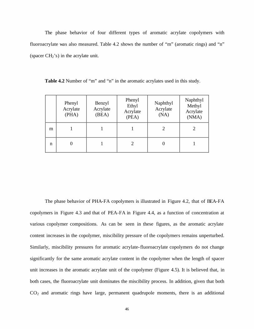
46
The phase behavior of four different types of aromatic acrylate copolymers with
fluoroacrylate was also measured. Table 4.2 shows the number of “m” (aromatic rings) and “n”
(spacer CH2’s) in the acrylate unit.
Table 4.2 Number of “m” and “n” in the aromatic acrylates used in this study.
Phenyl Acrylate (PHA)
Benzyl Acrylate (BEA)
Phenyl Ethyl
Acrylate (PEA)
Naphthyl Acrylate
(NA)
Naphthyl Methyl
Acrylate (NMA)
m 1 1 1 2 2
n 0 1 2 0 1
The phase behavior of PHA-FA copolymers is illustrated in Figure 4.2, that of BEA-FA
copolymers in Figure 4.3 and that of PEA-FA in Figure 4.4, as a function of concentration at
various copolymer compositions. As can be seen in these figures, as the aromatic acrylate
content increases in the copolymer, miscibility pressure of the copolymers remains unperturbed.
Similarly, miscibility pressures for aromatic acrylate- fluoroacrylate copolymers do not change
significantly for the same aromatic acrylate content in the copolymer when the length of spacer
unit increases in the aromatic acrylate unit of the copolymer (Figure 4.5). It is believed that, in
both cases, the fluoroacrylate unit dominates the miscibility process. In addition, given that both
CO2 and aromatic rings have large, permanent quadrupole moments, there is an additional

47
possibility that there would be substantial quadrupole-quadrupole interactions between CO2 and
aromatic ring, leading to an increase in solute-solvent interactions or quadrupole-quadrupole
interactions between aromatic-aromatic ring, leading to “micellization” and, hence, exclusion of
aromatic rings from CO2 solutions.
9
10
11
12
13
14
0 1 2 3 4 5 6
Concentration (wt%)
Clo
ud p
oint
pre
ssur
e (M
Pa)
1
2
3
4
Figure 4.2 Phase Behavior of PHA-FA Copolymer in CO2 at T=295 K (PHA: Phenyl Acrylate,
n=0, m=1; FA: Fluoroacrylate) 1) 31%PHA-69%FA, 2) 29%PHA-71%FA, 3) 26%PHA-74%FA,
4) 23%PHA-77%FA.

48
9
10
11
12
13
14
15
0 1 2 3 4 5 6Concentration (wt%)
Clo
ud p
oint
pre
ssur
e (M
Pa)
1
2
3
4
56
Figure 4.3 Phase Behavior of BEA-FA Copolymer in CO2 at T=295 K (BEA: Benzyl Acrylate,
n=1, m=1; FA: Fluoroacrylate), 1) 54%BEA-46%FA, 2) 38%BEA-62%FA, 3) 27%BEA-
73%FA, 4) 29%BEA-71%FA, 5) 18%BEA-82%FA, 6) 21%BEA-79%FA

49
9
10
11
12
13
14
0 1 2 3 4 5 6Concentration (wt%)
Clo
ud p
oint
pre
ssur
e (M
Pa) 1
2
3
45
Figure 4.4 Phase Behavior of PEA-FA Copolymer in CO2 at T=295 K (PEA: Phenyl ethyl
acrylate, n=2, m=1; FA: Fluoroacrylate),1) 36%PEA-64%FA, 2) 24%PEA-76%FA, 3) 26%PEA-
74%FA, 4) 25%PEA-75%FA, 5) 29%PEA-71%FA

50
9
10
11
12
13
0 1 2 3 4 5 6Concentration (wt%)
Clo
ud p
oint
pre
ssur
e (M
Pa)
1
2
3
Figure 4.5 Effect of spacer length on the phase behavior of copolymers in CO2 at T=295 K
(PHA: Phenyl acrylate, n=0, m=1; BEA: Benzyl acrylate, n=1, m=1; PEA: Phenyl ethyl acrylate,
n=2, m=1; FA: Fluoroacrylate), 1) 29%PHA-71%FA, 2) 29%BEA-71%FA, 3) 29%PEA-
71%FA.
Copolymers of naphthyl acrylate- fluoroacrylate at varying compositions were also
synthesized; phase behavior of naphthyl acrylate-fluoroacrylate copolymers is shown in Figure
4.6. Interestingly, the location of phase boundary does not change significantly with the
increasing content of naphthyl acrylate in the copolymer. Again, this is a result of the dominance
of the fluoroacrylate unit on miscibility pressures.

51
10
11
12
13
14
15
0 1 2 3 4 5 6Concentration (wt%)
Clo
ud p
oint
pre
ssur
e (M
Pa)
1
2
34
Figure 4.6 Phase Behavior of NA-FA Copolymer in CO2 at T=295 K (NA: Naphthyl acrylate,
n=0, m=2; FA: Fluoroacrylate), 1) 32%NA-68%FA, 2) 17%NA-83%FA, 3) 22%NA-78%FA, 4)
19%NA-81%FA
The effect of the number of aromatic rings in the acrylate unit on miscibility is illustrated
in Figure 4.7. As seen in the figure, despite its bulkiness, the presence of naphthyl unit in the
copolymer does not have a serious detrimental effect on miscibility pressures. The miscibility
pressure curve of a NA-FA copolymer is located very close to that of a PHA-FA copolymer of
the same aromatic acrylate content. As before, it is suggested that the highly CO2-philic
fluoroacrylate unit is controlling the miscibility of the NA-FA copolymers in CO2.

52
9
10
11
12
13
14
15
0 1 2 3 4 5 6Concentration (wt%)
Clo
ud p
oint
pre
ssur
e (M
Pa)
1
2
3
4
Figure 4.7 Phase Behavior of NA-FA and PHA-FA Copolymers in CO2 at T=295 K (NA:
Naphthyl acrylate; n=0, m=2; PHA: Phenyl acrylate, n=0, m=1, FA: Fluoroacrylate), 1) 32%NA-
68%FA, 2) 31%PHA-69%FA, 3) 22%NA-78%FA, 4) 23%PHA-77%FA
The miscibility pressures of various acrylate copolymers at similar compositions are
compared in Figure 4.8, namely PHA-FA, NA-FA, CHA-FA copolymers. Miscibility pressures
for the copolymers are again not distinguishable. It was reported earlier that phenyl rings are
much more rigid and much more dense than cyclohexyl rings, and thus, having greater stiffness
and high cohesive energy.83 In this case, one would expect that PHA-FA copolymers should be
less miscible with CO2 than CHA-FA copolymer. It seems that favorable quadrupole-quadrupole

53
interactions between CO2 and phenyl rings, and those between phenyl and phenyl rings are
compensating for this negative effect.
9
10
11
12
13
14
0 1 2 3 4 5 6Concentration (wt%)
Clo
ud p
oint
pre
ssur
e (M
Pa)
1
2
3
Figure 4.8 Phase Behavior of NA-FA, CHA-FA and PHA-FA Copolymers in CO2 at T=295 K
(CHA: Cyclohexyl acrylate, NA: Naphthyl acrylate; n=0, m=2; PHA: Phenyl acrylate, n=0, m=1,
FA: Fluoroacrylate), 1) 22%NA-88%FA, 2) 22%CHA-78%FA, 3) 23%PHA-77%FA
54
4.3 VISCOSITY BEHAVIOR RESULTS OF COPOLYMERS IN DENSE CO2
The power of polymers to influence fluid rheology arises from the high volume of a
macromolecule in solution and chain entanglements. Additional influence can be achieved by
means of intermolecular associations. These associations should be strong enough to give rise to
stable higher order macromolecular architectures, yet not form covalent crosslinks that would
hinder the miscibility of polymer chains in the solvent. Stacking of aromatic rings in the
copolymer is considered to be the primary force in this work for the intermolecular association
needed to raise the viscosity of CO2.
As mentioned before, viscosity enhancement ability of styrene-fluoroacrylate copolymers
forms the baseline of this particular study. Figure 4.9 shows viscosity enhancement ability of one
of the compositions of the styrene-fluoroacrylate copolymers and its partially sulfonated
analogue. Not surprisingly, the viscosity enhancement decreases as the concentration of polymer
in the solution decreases. The effect on viscosity is more pronounced with sulfonated copolymer
solution of CO2 compared to unsulfonated one, especially at higher wt% of the polymer in
solution. This might be explained by additional contribution from the attractive interaction
between partially positive charge of Na+ and π-face of aromatic ring98 along with stacking of
aromatic rings and/or stronger stacking tendency of the rings due to the change in their electronic
structure by substitution of electron withdrawing sulfonate salt.

55
0
30
60
90
120
150
0 1 2 3 4 5 6
Concentration (wt %)
Rel
ativ
e V
isco
sity
(η s
oln/
ηC
O2)
1
2
Figure 4.9 Relative viscosity of Sulfonated and Unsulfonated Styrene-Fluoroacrylate Copolymer
Solutions in CO2 as a function of concentration at T=295 K and P=41.4 MPa (St: Styrene, FA:
Fluoroacrylate, S.St: Sulfonated Styrene), 1) 0.1%S.St-10.9%St-89%FA, 2) 11%St-89%FA
Similar to styrene, aromatic acrylates in the copolymers have also the ability to increase
the viscosity of neat CO2. The degree of increase in viscosity depends on the structure of
aromatic acrylate and its content in the copolymer as shown in Figure 4.10, Figure 4.11 and
Figure 4.12. In these figures, viscosity increases with the addition of aromatic moiety; but after a
certain composition, additional increases in the content of the aromatic acrylate in the copolymer
causes viscosity to drop. The same effect was previously observed with styrene-fluoroacrylate

56
copolymers.26 The optimum composition for PHA-FA copolymers for maximum viscosity
enhancement is 29% PHA. The optimum for BEA-FA and PEA-FA copolymers were not
observed in the composition range studied here; but, because a homopolymer of fluoroacrylate
does not give rise to considerable increase in the viscosity of CO2,24 it is suggested that optimum
for BEA-FA and PEA-FA copolymers falls in the range of 0-18% BEA and 0-24% PEA,
respectively.
0
30
60
90
120
150
180
210
0 1 2 3 4 5 6
Concentration (wt %)
Rel
ativ
e V
isco
sity
(η
soln/ η
CO
2)
1
2
3
4
Figure 4.10 Relative viscosity of x%PHA-y%FA copolymer solutions in CO2 as a function of
concentration at T=295 K at varying copolymer composition, P=41.4 MPa, (PHA: Phenyl
Acrylate, n=0, m=1; FA: Fluoroacrylate), 1) 29%PHA-71%FA, 2) 26%PHA-74%FA, 3)
23%PHA-77%FA, 4) 31%PHA-69%FA
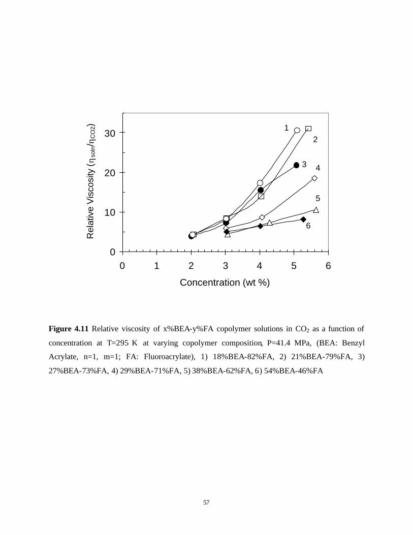
57
0
10
20
30
0 1 2 3 4 5 6
Concentration (wt %)
Rel
ativ
e V
isco
sity
(η
soln/ η
CO
2) 12
3 4
5
6
Figure 4.11 Relative viscosity of x%BEA-y%FA copolymer solutions in CO2 as a function of
concentration at T=295 K at varying copolymer composition, P=41.4 MPa, (BEA: Benzyl
Acrylate, n=1, m=1; FA: Fluoroacrylate), 1) 18%BEA-82%FA, 2) 21%BEA-79%FA, 3)
27%BEA-73%FA, 4) 29%BEA-71%FA, 5) 38%BEA-62%FA, 6) 54%BEA-46%FA

58
0
5
10
15
20
25
0 1 2 3 4 5 6
Concentration (wt %)
Rel
ativ
e V
isco
sity
( ηso
ln/ η
CO
2)
1
2
34
5
Figure 4.12 Relative viscosity of x%PEA-y%FA copolymer solutions in CO2 as a function of
concentration at T=295 K at varying copolymer composition, P=41.4 MPa, (PEA: Phenyl ethyl
acrylate, n=2, m=1; FA: Fluoroacrylate), 1) 24%PEA-76%FA, 2) 36%PEA-64%FA, 3)
25%PEA-75%FA, 4) 26%PEA-74%FA, 5) 29%PEA-71%FA
Although one would expect that increasing content of aromatic acrylates would increase
the number of crosslink points, after an optimum composition, due to the CO2-phobic nature of
the aromatic acrylates, the hydrodynamic volume of the coils decreases, such that the intrachain
attractive interactions dominate. Then, interaction becomes mostly intramolecular rather than
intermolecular, resulting in lower viscosity enhancement.
59
Although, initially, it was hypothesized that by increasing the length of the spacer unit
(number of n), the aromatic rings could relax to achieve the optimum stacking position resulting
in higher viscosity, it was experimentally observed that increasing spacer length has a reverse
effect on viscosity with the copolymers possessing only a single aromatic ring (Figure 4.13). It is
surmised that the difference between anticipated and the actual behavior results from the change
in electronic nature of the aromatic ring. It is suggested that, by changing electron density of the
ring with substituents, one can alter the magnitude of the interactions between closely aligned
aromatic rings.59 One way to determine the effect of substituent on electron density of the ring is
to look at the Hammett Sigma constant (σ), which is a measure of the effect of a given m- or p-
substituent on the acidity of benzoic acid (in other words, it represents the e-withdrawing or e-
donating power of a substituent ). The more positive σ is, the more e-withdrawing is the
substituent, similarly, the more negative σ is, the more e-releasing is the substituent. For
example, the Hammett Sigma constant (σ) is given as -0.15 and +0.31 for -CH(CH3)2 and –
OCOR, respectively. 99,100 The -CH(CH3)2 group, as in styrene, increases the electronic density of
the ring, on the other hand, the -OCOR group, as in phenyl acrylate, decreases electron density.
However, data are not available for benzyl acrylate and phenyl ethyl acrylate. It is possible that
both the spacer unit (σ=-0.17 for CH3 and σ=-0.15 for C2H5) and the –OCO group might have
combining effect on the electron density of the ring in the benzyl acrylate and phenyl ethyl
acrylate. Therefore, it is not easy to arrive at a solid conclusion on the effect of electronic
structure on the strength of interactions. In order to assess the effect of change of the electron
density of the ring on association of aromatic rings, it was attempted to synthesize 4-
bromobenzyl acrylate-FA copolymer, in which an e-withdrawing bromine at the para position
will compensate for the effect of e-donating power of CH2 (the value of σ is +0.23 for -Br and -

60
0.17 for CH3). However, the attempts to synthesize the copolymer resulted in failure because the
“critical conversion” was reached before obtaining enough polymer to evaluate due to H-
abstraction (chain transfer reactions) as explained in section 4.1.5.
0
30
60
90
120
150
180
210
0 1 2 3 4 5 6
Concentration (wt %)
Rel
ativ
e V
isco
sity
(η
soln/ η
CO
2)
1
2 3
Figure 4.13 Effect of spacer length on CO2-viscosity enhancement of copolymer solutions as a
function of concentration at T=295 K and P= 41.4 MPa, (BEA: Benzyl Acrylate, n=1, m=1;
PHA: Phenyl acrylate, n=0, m=1; PEA: Phenyl ethyl acrylate, n=2, m=1; FA: Fluoroacrylate), 1)
29%PHA-71%FA, 2) 29%PEA-71%FA, 3) 29%BEA-71%FA

61
The hydrodynamic volume of the polymer chain in CO2 solution is an important
parameter determining viscosity enhancement. Increased hydrodynamic volume is an indication
of swelling of polymer chains in the solution. When highly swollen, it is much easier for the
polymer chains to acquire intermolecular interactions rather than intramolecular. A number of
studies have investigated the change in polymer conformation as a function of solvent density in
supercritical fluids.101,102 Those works indicated that the polymer chains expand as the density of
supercritical fluid increases, screening attractive intrachain forces. In other words, solvent quality
of CO2 improves with pressure. This outcome was also reflected in our results, as higher
viscosity enhancement at higher system pressures (Figure 4.14). This result suggests that
associations between aromatic rings are more likely intermolecular rather than intramolecular
due to the chain expansion induced by pressure (higher hydrodynamic volume). The same effect
of pressure was also observed with BEA-FA and PEA-FA copolymers.

62
0
30
60
90
120
150
180
210
0 1 2 3 4 5 6
Concentration (wt %)
Rel
ativ
e V
isco
sity
( ηso
ln/ η
CO
2)
1
2
3
4
Figure 4.14 The effect of pressure on relative viscosity of 29%PHA-71%FA copolymer
solutions in CO2 as a function of concentration at T=295 K (PHA: Phenyl Acrylate, n=0, m=1;
FA: Fluoroacrylate), 1) P=41.4 MPa, 2) P=34.5 MPa, 3) P=27.6 MPa, 4) P=20.7 MPa.
Success in designing effective CO2 thickeners in the present work was arisen from
discovering suitable polymer groups that have the ability to associate in CO2 to form stable
supramolecular structures. One can question whether the association of the aromatic rings is the
key governing viscosity enhancement of CO2. In order to investigate this, the copolymer of
fluoroacrylate with a cycloaliphatic acrylate, namely cyclohexyl acrylate, was synthesized.
Cyclohexyl acrylate is analogous to phenyl acrylate in structure, where the aromatic ring is
replaced with an unsaturated, cyclic ring. Results showed that presence of aromatic rings plays

63
the key role in viscosity enhancement. Figure 4.15 compares the viscosity enhancement ability of
CHA-FA and PHA-FA copolymers at similar compositions, and Figure 4.16 does so at their
optimum composition.
0
10
20
30
40
50
60
70
80
0 1 2 3 4 5 6
Concentration (wt %)
Rel
ativ
e V
isco
sity
( ηso
ln/ η
CO
2)
1
2
Figure 4.15 Comparison of aromatic and non-aromatic rings on CO2-viscosity enhancement at
similar compositions at T=295 K and P=41.4 MPa as a function of concentration (PHA: Phenyl
Acrylate; CHA: Cyclohexyl Acrylate; FA: Fluoroacrylate), 1) 26%PHA-74%FA, 2) 27%CHA-
73%FA.

64
0
40
80
120
160
200
240
0 1 2 3 4 5 6
Concentration (wt %)
Rel
ativ
e V
isco
sity
( ηso
ln/ η
CO
2)
1
2
Figure 4.16 Comparison of aromatic and non-aromatic rings on CO2-viscosity enhancement at
their optimum composition at T=295 K and P=41.4 MPa as a function of concentration (PHA:
Phenyl Acrylate; CHA: Cyclohexyl Acrylate; FA: Fluoroacrylate), 1) 29%PHA-71%FA, 2)
16%CHA-84%FA.
In the present study, it was initially hypothesized that by increasing the surface area of
aromatic structure, one might get stronger association between rings, and thus higher viscosity
enhancement. Figure 4.17 compares the effect of size of the aromatic functional group on
viscosity enhancement at similar compositions, and Figure 4.18 does so at the optimum
compositions. For the same composition of acrylate unit in the copolymer, results showed that
single aromatic ring (referring to PHA-FA copolymer) produces a better viscosity enhancement

65
than two aromatic rings (referring to NA-FA copolymer) in the acrylate unit (Figure 4.17).
However, at their optimum composition, single and double ring in the aromatic acrylate unit
show similar effect on viscosity enhancement at low concentrations; but, at higher
concentrations, there is a considerable difference between viscosity enhancement of PHA-FA
and NA-FA copolymers (Figure 4.18). There is a possibility that association between the bulky
naphthyl rings is made difficult due to obstruction from long polymer backbone.
0
10
20
30
40
50
0 1 2 3 4 5 6
Concentration (wt %)
Rel
ativ
e V
isco
sity
( ηso
ln/ η
CO
2)
1
2
Figure 4.17 Comparison of effect of size of aromatic rings on viscosity enhancement ability of
CO2 at similar compositions at T=295 K and P=41.4 MPa as a function of concentration (PHA:
Phenyl acrylate; NA: Naphthyl acrylate; FA: Fluoroacrylate), 1) 23%PHA-77%FA, 2) 22%NA-
78%FA.

66
0
40
80
120
160
200
240
0 1 2 3 4 5 6
Concentration (wt %)
Rel
ativ
e V
isco
sity
(η s
oln/
ηC
O2)
1
2
Figure 4.18 Comparison of effect of size of aromatic rings on viscosity enhancement ability of
CO2 at their optimum compositions at T=295 K and P= 41.4 MPa as a function of concentration
(PHA: Phenyl acrylate; NA: Naphthyl acrylate; FA: Fluoroacrylate), 1) 29%PHA-71%FA, 2)
32%NA-68%FA.
In an effort to understand the need for a spacer for favorable associations of rings in
naphthyl acrylate, it was attempted to synthesize naphthyl methyl acrylate- fluoroacrylate
copolymer (NMA-FA, m=2, n=1) so that naphthyl rings can relax to an optimum geometry to
achieve the strongest interactions via spacer. Unfortunately, enough copolymer yield could not
be obtained before the “critical conversion” was reached due to the chain transfer reactions.

67
Therefore, at present, why relative viscosity diminishes with increasing size of the aromatic
group cannot be explained.
In general, one might argue that the differences in relative viscosities might be a result of
the differences in molecular weights. Unfortunately, it is not possible to measure the molecular
weight of the polymers studied due to insolubility of the polymers in traditional GPC solvents.
Intrinsic viscosity is the most useful of the various viscosity expressions because it can be related
to molecular weight by the Mark-Houwink equation:
[ ] aMK ⋅=η (4.4)
where [η] and M are the intrinsic viscosity and the molecular weight of the chain, respectively. K
and a are the constants for a given polymer-solvent-temperature system. The exponent a
increases with the solvent power of the medium. Intrinsic viscosity is related to relative viscosity
(ηrel), which is the viscosity of a polymer solution (η) divided by the viscosity of the pure solvent
(ηo), in the dilute regime as follows:
[ ] c1o
rel ⋅η+=ηη=η (4.5)
where c is the concentration. As one can see, if molecular weight of a polymer is doubled,
intrinsic viscosity changes as
[ ] [ ] aM 2
M2⋅η=η (4.6)

68
where [η]M and [η]2M are the intrinsic viscosities when molecular weights are M and 2M,
respectively. After substituting this equation in Eq, 4.5 and taking the ratio of relative viscosities:
[ ]
[ ] c1
c21
M
aM
M,rel
M2,rel
+η
⋅+η=
η
η (4.7)
For randomly coiled polymers, the exponent a varies from 0.5 (theta solvent) to 0.8 (good
solvent). As can be seen, when the molecular weight is doubled, the increase in relative viscosity
is always less than 2. However, observed differences in relative viscosities in this work are much
larger than 2. This suggests that the structural effects play a more significant role than molecular
weights in viscosity increase of CO2 solution. Moreover, it was previously observed that the
homopolymer of fluoroacrylate does not induce any significant increase in the viscosity of a CO2
solution due to lack of associating groups.26
The relative viscosity enhancement of NA-FA copolymer with va rying content of
naphthyl acrylate is illustrated in Figure 4.19. The results showed that the increasing content of
the naphthyl unit in the copolymer is desirable to obtain better enhancement in viscosity. As
explained before, with the increase in the naphthyl unit content, the number of interaction points
increases, leading to better viscosity enhancement.

69
0
10
20
30
40
50
60
0 1 2 3 4 5 6
Concentration (wt %)
Rel
ativ
e V
isco
sity
( ηso
ln/ η
CO
2)
1
2
3
4
Figure 4.19 Relative viscosity of x%NA-y%FA copolymer solutions in CO2 as a function of
concentration at T=295 K at varying copolymer composition, and P=41.4 MPa, (NA: Naphthyl
Acrylate, n=0, m=2; FA: Fluoroacrylate), 1) 32%NA-68%FA, 2) 19%NA-81%FA, 3) 17%NA-
83%FA, 4) 22%NA-78%FA
As mentioned before, with increasing pressure, CO2 becomes a better solvent for the
polymer, causing the polymer coil to swell to higher degree (larger hydrodynamic volume).
Consequently, intermolecular interactions between the rings become more likely than
intramolecular interactions, leading to formation of a large structures, which can increase the
viscosity to higher extents. That is, at larger hydrodynamic volume, higher viscosity
enhancement is observed, as one can see in NA-FA copolymers (Figure 4.20).

70
0
10
20
30
40
50
60
0 1 2 3 4 5 6
Concentration (wt %)
Rel
ativ
e V
isco
sity
( ηso
ln/ η
CO
2)
1
2
3
4
Figure 4.20 The effect of pressure on relative viscosity of 32%NA-68%FA copolymer solutions
in CO2 as a function of concentration at T=295 K (NA: Naphthyl Acrylate, n=0, m=2; FA:
Fluoroacrylate), 1) 41.4 MPa, 2) 34.5 MPa, 3) 27.6 MPa, 4) 20.7 MPa.
4.4 CONCLUSIONS
The effect of the structure of copolymers of aromatic acrylate- fluoroacrylate on the viscosity
enhancement of CO2 was investigated. For this purpose, a series of aromatic acrylate-
fluoroacrylate copolymers were synthesized. The change in the series was produced by
systematically changing either spacer length (between the ring and carbonyl unit), or the number
of aromatic rings, or both in the aromatic acrylate unit of the copolymer. In general, these

71
copolymers were all found to be miscible with CO2 at 295 K and induce an increase in the
viscosity to some degree, depending upon the type and content of aromatic acrylate unit in the
copolymer. It was shown that stacking of aromatic rings is the key factor in viscosity
enhancement.
Location of miscibility pressure curves of the copolymers was found not to be strongly
affected by the type and/or content of the aromatic acrylate unit. This was attributed to the
dominance of the highly CO2-philic fluoroacrylate unit in the copolymer on miscibility.
It was also observed that the increasing the length of the spacer unit has a negative effect
on viscosity, such that the maximum viscosity was observed in the case of the PHA-FA
copolymer. Results, especially in the case of PHA-FA copolymers, showed that viscosity of the
solution increases with the increasing content of the aromatic acrylate unit in the copolymer, but
a point is reached beyond which additional increase causes the relative viscosity to drop.
Existence of such an optimum composition suggests that, beyond an optimum, the aromatic rings
associate through intramolecular rather than intermolecular interactions, resulting in a decrease
in viscosity enhancement. It is surmised that the decreasing affinity of CO2 for the copolymer
with increasing content of aromatic acrylate unit in the copolymer (i.e. decreasing hydrodynamic
volume) is simply the cause for this effect.
Increase in viscosity was found to be dependent on the pressure of the solution; higher
viscosities were measured at higher pressures. This is again simply due to CO2 becoming a

72
weaker solvent for the polymer at lower pressures, resulting in a switch in the type of association
from intermolecular to intramolecular.
At present, it is difficult to comment about the size of aromatic ring on viscosity
enhancement. Naphthyl rings do have an ability to induce a raise in viscosity of neat CO2 to
some extent.
Being aware of the high cost of the fluoroacrylates and their insolubility in crude oil, the
current study was extended to investigation of inexpensive, non-fluorous, CO2-philic polymers to
improve the viability of the EOR process. Therefore, the following chapters focus on the design
and synthesis of polymers composed of inexpensive building blocks.

73
5.0 EFFECT OF GRAFTED LEWIS BASE GROUPS ON THE PHASE BEHAVIOR OF
MODEL POLY (DIMETHYL SILOXANES) IN CO2
5.1 INTRODUCTION
This particular study has aimed to evaluate the impact of various Lewis bases on the miscibility
of polymers in CO2. Methylhydrosiloxane-dimethylsiloxane copolymers (with a total of 25
repeat units and a varying number of methylhydro units for grafting reaction) were chosen as
model backbones because of their low glass transition temperature and relatively low cohesive
energy density. By placing a series of side cha ins containing various Lewis bases and varying the
amounts of those side chains onto constant chain- length silicone backbones, the effect of each
chain and the extent of substitution on phase behavior in CO2 were examined independently.

74
5.2 EXPERIMENTAL PROTOCOL
5.2.1 Materials:
Copolymers of methylhydrosiloxane-dimethylsiloxane (Table 5.1) and platinum-(vinyl
tetramethyldisiloxane) complex in xylene (low color) were purchased from Gelest (Tullytown,
PA). Anhydrous toluene, allyl ethyl ether, allyl acetate, allyl methyl carbonate, methyl-3-
butenoate, 5-hexen-2-one were obtained from Aldrich. N,N-Dimethyl allylamine was purchased
from Fisher Scientific. All materials were used without additional purification. Ultra-high purity
argon was purchased from Praxair.
Table 5.1 Methylhydrosiloxane-dimethylsiloxane copolymers(a) used
in this study
Entry Mole %
MeHSiO
Mole %
Me2SiO
z
# of Si-H
1 3.5 96.5 1
2 6.5 93.5 2
3 16.5 83.5 5
4 27.5 72.5 11
5 100 0 25
(a) Total chain length of the copolymers is 25 repeat units

75
5.2.2 Synthesis of Lewis Base Grafted Siloxane Polymers:
Grafted copolymers were synthesized via a hydrosilylation reaction between an allyl compound
and a methylhydrosiloxane-dimethylsiloxane copolymer,103 as shown in Scheme 5.1. Glassware
was oven-dried overnight and purged with ultra-high purity argon before use. In a typical
experiment, 10 g (27.5 mmol Si-H) of 16.5 mole% methylhydro containing copolymer and 3.3 g
(33.0 mmol) allyl acetate were charged to a 250 ml three-neck, round-bottomed flask, equipped
with a magnetic stir-bar, a condenser, and an argon feed. 60 ml of anhydrous toluene and 100 mg
of platinum-vinyl tetramethyldisiloxane complex in xylene (low color) were added to the
reaction mixture. The solution was stirred for 3 – 4 hours at room temperature under an argon
atmosphere, then heated to 45 °C and stirred overnight. During heating the color of the solution
turned a slight brownish-yellow. The reaction was monitored using FT-IR, where the
disappearance of the Si-H band at 2157 cm-1 was used to establish the point at which the
hydrosilylation reaction had gone to completion (Figure B.1 in Appendix B,). 0.3 g of
decolorizing carbon was then added to the hot solution, and the mixture was stirred at 65 °C for
1–2 hours. The solution was then filtered while hot. Upon evaporation of the solvent under
reduced pressure, a slightly yellow copolymer was isolated. Completion of the reaction was also
verified using 1H-NMR (300 MHz Bruker) by following the disappearance of the peak at 4.7
ppm (corresponding to Si-H), (Figure B.2-Figure B.5 in Appendix B).

76
5.2.3 Structural Characterization:
Infrared spectra were obtained on a Madison Instruments Inc. Research Series FT-IR
spectrometer, and the samples were prepared as a thin film between two NaCl windows.
Disappearance of the Si-H stretching at 2157 cm-1 was indication of completion of the
hydrosilylation reaction. Grafted siloxane copolymers were characterized using 1H-NMR
(Bruker DMS 300) where the samples were dissolved in d-chloroform. All chemical shifts were
referenced to tetrametylsilane (TMS) at zero ppm. Disappearance of the peak at 4.7 ppm
(corresponding to Si-H) was also indication of the completion of hydrosilylation reaction.
Complete removal of starting allyl material was verified by the disappearance of the allyl double
peaks typically located between 5 and 6 ppm.
Figure B.1 in Appendix B shows the FT-IR spectra of (z=5) propyl acetate- functional
siloxane copolymer before and after hydrosilylation reaction, as an example. 1H-NMR spectra of
(z=5)-functional siloxane copolymers are presented in Figures B.2-B.5 in Appendix B.
Following is the 1H-NMR peak data for the grafted siloxane copolymers: Methylhydrosiloxane:
δ 0.1 (broad, 3H, Si-CH3), δ 4.7 (s, 1H, Si-H), Propyl acetate: δ 0.54 (broad, 2H, Si-CH2-CH2),
δ 1.58 (broad, 2H, Si-CH2-CH2), δ 2.06 (s, 3H, O-CO-CH3), δ 4.03 (t, 2H, CH2-CH2-O-CO-
CH3). Methyl butyrate: δ 0.58 (t, 2H, Si-CH3), δ 1.73 (broad, 2H, Si-CH2-CH2), δ 2.37 (t, 2H,
CH2-CO-O-CH3), δ 3.7 (s, 3H, CO-O-CH3). Propyl methyl carbonate : δ 0.48 (broad, 2H, Si-
CH2), δ 1.66 (broad, 2H, Si-CH2-CH2), δ 3.71 (s, 3H, -O-CO-O-CH3), δ 4.04 (t, 2H, -CH2-O-
CO-O). Propyl dimethylamine: δ 0.54 (broad, 2H, Si-CH2), δ 1.01 (broad, 2H, CH2-N(CH3)2),
δ 1.54 (broad, 2H, Si-CH2-CH2), δ 2.2 (d, 6H, CH2-N(CH3)2). Butyl methyl ketone:124 δ 0.52 (t,

77
2H, Si-CH2-CH2), δ 1.36 (broad, 2H, Si-CH2-CH2-CH2), δ 1.61 (2H, Si-CH2-CH2-CH2), δ 2.14
(s, 3H, -CH2-CO-CH3), δ 2.42 (t, 2H, -CH2-CO-CH3). Propyl ethyl ether:124 δ 0.63 (broad, 2H,
Si-CH2-CH2), δ 1.31 (t, 3H, -O-CH2-CH3), δ 1.75 (2H, Si-CH2-CH2-CH2), δ 3.49 (2H, -O-CH2-
CH3), δ 359 (2H, Si-CH2-CH2-CH2-O-)
5.2.4 Phase Behavior Measurements:
Phase behavior measurements of the siloxane copolymers were performed in the same manner as
described in section 4.1.8.

78
O
C O
Pt catalyst
R
R
z=1,2,5,11,25
Si O Si Oz 25-z
H
Si O Si Oz 25-z
Propyl acetate
(PA)
Methyl
butyrate (MB)
Butyl(a)
methyl ketone (BMK)
Propyl methyl
carbonate (PMC)
Propyl(a)
ethyl ether (PEE)
Propyl
dimethyl amine (PDA)
R
Group
O
C O
C O
CH2
O
C O
O
O
N
Scheme 5.1 Synthetic route for preparation of grafted silicone polymers and structures of
functional groups. (a) Ref. 124

79
5.3 PHASE BEHAVIOR RESULTS OF LEWIS BASE GRAFTED SILOXANE
POLYMERS
Poly(siloxanes) are probably the most CO2-philic polymers known other than fluoroacrylates.
Although it has been suggested that there is a favorable specific interaction between the oxygens
of CO2 and Si atoms,104 their solubility in CO2 is mostly attributed to their low glass transition
temperature (and thus high chain flexibility) and relatively low cohesive energy density.44 High
chain flexibility can be attributable to the longer bond length of silicone atoms compared to
carbon atoms to their neighbors, and the much lower force constants for bond stretching, bending
and torsional motions for Si-C versus C-C bonds.105,106,107,108
Previous studies show that CO2 can act as both a Lewis acid and a Lewis base29,32,109,110
However, the Lewis acidity of CO2 has occupied most of the attention where the solubility of
polymers in CO2 is concerned. Therefore, efforts typically focus on incorporation of Lewis bases
into a polymer chain to enhance the solubility in CO2 via Lewis acid-base complex formation.
For example, Fink et al. generated silicone polymers with propyl acetate and with hexyl groups
in the side chain. They found that the propyl acetate functionalized polymer is miscible with CO2
at significantly lower pressures than the hexyl functionalized polymer, attributing this result to
specific interactions between the side chain carbonyl and CO2.103 Similarly, in a recent study,
Shen et al. investigated the CO2 solubility of various oligomers and polymers that contain the
carbonyl group. Among poly(vinyl formate), poly(methyl acrylate), poly(vinyl acetate) and
poly(lactide), poly(vinyl acetate) was found to exhibit the lowest miscibility pressures in CO2.56

80
One aim of this work was to clarify the effect of the carbonyl group structure on phase
behavior of CO2-polymer solutions for future design of CO2-philes. Due to the low glass
transition temperature and relatively low cohesive energy density, methylhydrosiloxane-
dimethylsiloxane copolymers were chosen as model polymers, and carbonyl containing groups
were incorporated into the polymers by a hydrosilation reaction with an allylic precursor. The
silicone copolymers all have a total of 25 repeat units, in which the number of methylhydro units
available for hydrosilylation varies from one to twenty five. By placing the carbonyl containing
side chains on a constant length backbone, the effect of backbone chain length on the phase
behavior was eliminated, and thus the effects of each side chain and the degree of substitution
were ascertained independently. Similar investigations were performed with two additional
Lewis base functionalities, ether and tertiary amine.
Figure 5.1 illustrates the phase behavior of two poly(siloxanes) with isomeric pendant
units, namely propyl acetate (PA) and methyl butyrate (MB) (Scheme 5.2). Although these side
chains are isomers, Figure 5.1 shows that the miscibility pressures are higher for the MB-
functional polymer than that for PA-functional analog.

81
0
5
10
15
20
25
0 1 2 3 4 5 6Polymer Concentration (wt %)
Clo
ud P
oint
Pre
ssur
e (M
Pa)
1
2
Figure 5.1 Phase behavior of functionalized (z=5) siloxane copolymers, 1) methyl butyrate
(MB), 2) propyl acetate (PA), at 295 K.
Similarly, McHugh et al. reported that the miscibility pressures for poly(vinyl acetate) are
much lower than those for poly(methyl acrylate), despite a much higher molecular weight for
poly(vinyl acetate) in their study.55 These authors stated that the ether oxygen in poly(vinyl
acetate) acts as a spacer between the main chain and carbonyl group, providing the necessary
free volume to allow CO2 to interact with each carbonyl oxygen. Here, however, accessibility to
the carbonyl group was not an issue, since each carbonyl moiety is separated from the backbone
by a propyl chain. Using ab initio calculations, Wallen et al. suggested that a weaker, but
cooperative C-H…O hydrogen bond between the hydrogen of the acetate methyl group and
oxygen of the CO2, along with the stronger Lewis acid-Lewis base interaction of the carbonyl

82
oxygen and the carbon of CO2, is responsible for the enhanced solubility of acetate functional
compounds in CO2. However, it was observed that the keto-functional analog (BMK, Scheme
5.2) is miscible at significantly higher pressures than PA-functional analog (Figure 5.2). Despite
both the separation of the carbonyl functionality from the backbone by a butyl chain and the
presence of protons attached to the α-carbons for cooperative interactions with CO2 in BMK side
chain, the cloud point curve for BMK-functional polymer is located at higher pressures than that
for the PA-functional analog. Hence, neither McHugh’s nor Wallen’s rationale for the enhanced
miscibility of acetate structures seems operative here.
0
5
10
15
20
25
0 1 2 3 4 5 6Polymer Concentration (wt %)
Clo
ud P
oint
Pre
ssur
e (M
Pa)
1
2
Figure 5.2 Phase behavior of functionalized (z=5) siloxane copolymers 1) butyl methyl ketone
(BMK), 2) propyl acetate (PA), at 295 K.
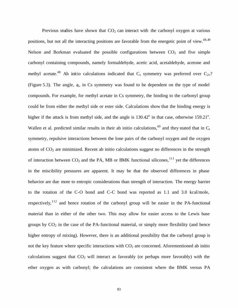
83
Previous studies have shown that CO2 can interact with the carbonyl oxygen at various
positions, but not all the interacting positions are favorable from the energetic point of view.48,49
Nelson and Borkman evaluated the possible configurations between CO2 and five simple
carbonyl containing compounds, namely formaldehyde, acetic acid, acetaldehyde, acetone and
methyl acetate.48 Ab initio calculations indicated that Cs symmetry was preferred over C2ν?
(Figure 5.3). The angle, a2, in Cs symmetry was found to be dependent on the type of model
compounds. For example, for methyl acetate in Cs symmetry, the binding to the carbonyl group
could be from either the methyl side or ester side. Calculations show that the binding energy is
higher if the attack is from methyl side, and the angle is 130.42o in that case, otherwise 159.21o.
Wallen et al. predicted similar results in their ab initio calculations,49 and they stated that in Cs
symmetry, repulsive interactions between the lone pairs of the carbonyl oxygen and the oxygen
atoms of CO2 are minimized. Recent ab initio calculations suggest no differences in the strength
of interaction between CO2 and the PA, MB or BMK functional silicones,111 yet the differences
in the miscibility pressures are apparent. It may be that the observed differences in phase
behavior are due more to entropic considerations than strength of interaction. The energy barrier
to the rotation of the C-O bond and C-C bond was reported as 1.1 and 3.0 kcal/mole,
respectively,112 and hence rotation of the carbonyl group will be easier in the PA-functional
material than in either of the other two. This may allow for easier access to the Lewis base
groups by CO2 in the case of the PA-functional material, or simply more flexibility (and hence
higher entropy of mixing). However, there is an additional possibility that the carbonyl group is
not the key feature where specific interactions with CO2 are concerned. Aforementioned ab initio
calculations suggest that CO2 will interact as favorably (or perhaps more favorably) with the
ether oxygen as with carbonyl; the calculations are consistent where the BMK versus PA

84
functional behavior is concerned, but would not explain the differences between PA and MB
functional analogs.
O C
O
C
a1
O
O
C
O
C
O
a2
(a) (b)
Figure 5.3 CO2-carbonyl interactions having a) C2ν b) Cs symmetry
Interestingly, the cloud point curve for the PMC-functionalized polymer is located at
higher pressures than that for the PA-functionalized one (Figure 5.4). However, one should
consider that the side chain in PMC is one atom longer. Apparently, the unfavorable entropic
effect of the increased chain length more than negates the effect that an additional oxygen might
have on specific binding of CO2. As seen in Figure 5.4, whereas there are substantial differences
in miscibility pressures at some concentrations in the P-x diagram, the curves become coincident
at lower and high concentrations. This latter feature is required, as all of the P-x diagrams must
intersect the y-axis at CO2’s vapor pressure, and also must pass through the vapor pressures of
the siloxane polymers (which are all essentially zero) at the 100% polymer axis.

85
As one can see, the shape of the cloud point curve changes as one alters the nature of the
pendant group. In general, when a change in structure prompts a drop in cloud point pressures, it
also tends to render the cloud point curve “flatter”, less sensitive to concentration. This can be
explained phenomenologically by examining the definition for changes in Gibbs free energy at
constant temperature, namely:
dG = VdP + Sµidni (5.1)
As the polymer is added to the solution, the chemical potential is changed and the free energy
perturbed; changes to the pressure balance this perturbation in the free energy. As such, if one
examines two cloud point curves where one is relatively flat while the other is steep, this could
be due to (a) substantial differences in the compressibility of the two mixtures, or (b) substantial
differences in the sensitivity of the chemical potential to changes in polymer concentration. If (a)
were true, then one would expect that the mixture associated with the “flatter” curve would have
a significantly higher compressibility than that associated with the steep curve; a smaller
pressure change is then required for the case of the flat curve to counteract the free energy
perturbation caused by adding polymer to the mixture. However, all of the mixtures in this study
are relatively dilute in polymer, and hence one would not expect to see dramatic differences in
compressibility. One therefore expect that option (b) is more likely; “flat” cloud point curves
represent cases where the chemical potential is relatively insensitive to polymer concentration.
Indeed, this suggests that mixing is favorable, and hence a relatively flat cloud point curve may
simply be one of the more obvious signs of a “CO2-philic” material.

86
0
5
10
15
20
25
0 1 2 3 4 5 6Polymer Concentration (wt %)
Clo
ud P
oint
Pre
ssur
e (M
Pa)
1
2
Figure 5.4 Phase behaviors of functionalized (z=5) siloxane copolymers, 1) propyl methyl
carbonate (PMC), 2) propyl acetate (PA) at 295 K.
Figure 5.5 compares the miscibility pressures of two methylhydro-dimethylsiloxane
copolymers (z=1 and 2) versus poly(dimethylsiloxane) at the same chain length. The figure
reveals that poly(dimethylsiloxane) (z=0) is miscible at slightly higher pressures than a one Si-H
functional siloxane copolymer (z=1), but at slightly lower pressures than a two Si-H functional
siloxane copolymer (z=2). Typically, it was found that miscibility of the polymer requires higher
pressures when the number of Si-H groups in the chain increases; why a one Si-H functional
siloxane copolymer (z=1) is miscible slightly at lower pressures than fully methylated siloxane
polymer (Polydimethylsiloxane, z=0) still remains as an unanswered question.

87
0
5
10
15
20
25
0 1 2 3 4 5 6Polymer Concentration (wt %)
Clo
ud P
oint
Pre
ssur
e (M
Pa)
1
2
3
Figure 5.5 Comparison of phase behaviors of hydromethyl-dimethyl siloxane copolymers at
varying functionality with a total of 25 repeat units, at 295 K, 1) z=2, 2) z=0, 3) z=1.
Each carbonyl containing functional group in this study has a higher cohesive energy
density than an Si(CH3)2 unit. While it is known that CO2 exhibits favorable interactions with
carbonyl groups, the carbonyl-containing polymer can only dissolve in CO2 if favorable cross-
interactions between polymer and CO2, plus the entropy of mixing, outweigh the sum of the CO2
and polymer self- interactions. The experimental results showed that this balance is best achieved
at different degrees of substitution for different side chain functional groups, as seen in Figure
5.6-Figure 5.8. For the propyl acetate functional polymers, miscibility pressures of the (z=5)
polymer are lower than those of the (z=1) and (z=2) analogs (Figure 5.6). Increasing the number
of side chains increases the number of carbonyl-CO2 contacts per chain; however, with eleven

88
side chains the increase in cohesive energy density of the polymer dominates over cross
interactions, disfavoring dissolution of polymer in CO2. Although PA and MB are similar in their
chemical structure, it seems that self- interactions always outweigh cross- interactions for MB-
functional materials (Figure 5.7), with each additional MB side chain the polymer becomes less
CO2-philic and the cloud point curves moves progressively to higher pressures. Because the
interaction of CO2 with the MB carbonyl is apparently not as favorable as with the PA carbonyl
(perhaps because of the rotational barrier as explained above), self- interactions govern the
dissolution process. Therefore, there was no obvious optimum number of side chains observed
with MB-functional siloxane copolymers.
0
10
20
30
40
0 1 2 3 4 5 6Polymer Concentration (wt %)
Clo
ud P
oint
Pre
ssur
e (M
Pa)
1
2
3
4
Figure 5.6 Phase behavior of propyl acetate (PA)-functionalized siloxane copolymers at
different degree of substitution 1) z=11, 2) z=1, 3) z=2, 4) z=5, at 295 K.

89
0
5
10
15
20
25
30
35
0 1 2 3 4 5 6Polymer Concentration (wt %)
Clo
ud P
oint
Pre
ssur
e (M
Pa)
1
23
4
Figure 5.7 Phase behaviors of methyl butyrate (MB)-functionalized siloxane copolymers at
different degree of substitution 1) z=11, 2) z=2, 3) z=5, 4) z=1, at 295 K.
0
10
20
30
40
50
0 1 2 3 4 5Polymer Concentration (wt %)
Clo
ud P
oint
Pre
ssur
e (M
Pa)
1
2
3
4
Figure 5.8 Phase behavior of propyl ethyl ether-functionalized siloxane copolymers at different
degree of substitution 1) z=11, 2) z=5, 3) z=1, 4) z=2, at 295 K.

90
Although there are apparently no literature spectroscopic measurements of ether-CO2
interactions at high pressure, Drohmann et al. concluded that the ether oxygen behaves as a weak
base towards CO2113 because they found that poly(propylene oxide) is miscible with CO2 at
approximately the same or just slightly higher pressures than poly(butadiene) despite the fact that
the latter possesses lower Tg and cohesive energy density. Indeed, the electron donor capacity of
ethers is slightly larger than that of carbonyls.114 Specific interactions between carbonyl groups
and CO2 have received significant attention in the literature, from both experimental and
theoretical perspective. Ether-CO2 interactions, by contrast, have received less attention, perhaps
because of the perception that such interactions are too weak to make much of an impact on the
thermodynamics of mixing. Ab initio calculations strongly suggest that ether will interact at least
as favorably with CO2 as carbonyls,111 and because they add less to the cohesive energy density
of a material, they could prove to be far more important than carbonyls in the design of CO2-
philic materials, if judiciously employed. Indeed, aforementioned ab initio calculations also
suggest that CO2 interacts with the ether oxygen in ester groups with the same interaction energy
as with the carbonyl.
Cloud point curves of PEE-functionalized polymers with varying number of side chains
are shown in Figure 5.8. The cloud point curve shifts to slightly lower pressures as the number of
ether side chains increases from one to two, yet the cloud point pressure curve moves to higher
pressures when the number of side chains increases to five and eleven. Because the ether
segment is flexible, it enhances the flexibility of the resulting polymer and hence entropy of
mixing. As mentioned above, ethers add the less to the cohesive energy density of resulting
polymer compared to other groups employed in this study.115 In addition, ab initio calculations

91
show that specific interactions between ethers and CO2 should be relatively favorable.111
Naturally, as one adds additional ether- functional side chains to the silicone, one also increases
molecular weight and adds a number of methylene groups; these additions will detract from the
CO2-philicity of the material, leading to the observed optimum in miscibility pressures in
Figure 5.8.
Figure 5.9 compares the phase behavior of (z=2) PA-, BMK- and PEE-functional silicone
polymers in CO2. It is noteworthy that, according to the Van Krevelen group contribution
theory,115 the ether produces the lowest contribution to the cohesive energy of the three
functional groups. The cohesive energy density of the groups decreases in the order of acetate,
ketone, ether, and the polymers’ miscibility pressures are located in the order of their cohesive
energy. Even if these functional groups add to the cohesive energy density of the polymer,
favorable cross- interactions with CO2 could compensate, promoting the formation of single
phase solution.

92
0
10
20
30
0 1 2 3 4 5Polymer Concentration (wt %)
Clo
ud P
oint
Pre
ssur
e (M
Pa) 1
2
3
Figure 5.9 Phase behaviors of (z=2) functional siloxane copolymers with 1) Propyl acetate (PA),
2) Butyl methyl ketone (BMK), 3) Propyl ethyl ether (PEE) at 295 K.
The phase behavior of polymers with degree of substitution five (z=5) is shown in Figure 5.10.
This time, cloud point pressure curves of the polymers do not appear in the order of their
cohesive energy density. The (z=5) PA-substituted polymer is miscible at lower pressures than
the PEE-substituted analog. This indicates that despite its addition to cohesive energy density,
the acetate- functionalized chain is more CO2-philic due to favorable Lewis acid-base
interactions. From Figure 5.9 and Figure 5.10, it can be concluded that, although it seems that
solubility of a polymer can be enhanced by increasing the number of cross- interactions with
CO2, the solubility of the polymer in fact depends on whether self- or cross-interaction are

93
dominant. Miscibility pressures may rise or fall with the addition of each side chain (Figure 5.7),
or may exhibit an optimum, as seen in Figure 5.6 and Figure 5.8.
0
10
20
30
40
50
0 1 2 3 4 5 6Polymer Concentration (wt %)
Clo
ud P
oint
Pre
ssur
e (M
Pa) 1
2
3
Figure 5.10 Phase behaviors of (z=5) functional siloxane copolymers with 1) Propyl ethyl ether
(PEE), 2) Butyl methyl ketone (BMK), 3) Propyl acetate (PA), at 295 K.
The effect of tertiary amine substitution on CO2-solubility was also investigated. A
tertiary amine is a much stronger Lewis base than either a carbonyl or ether.114 Figure 5.11
compares the phase behavior of a PDA-functionalized polymer with a PA-functionalized analog
at their optimum number of side chains. According to group contribution model by Fedor,115 a
tertiary amine contributes less to the cohesive energy of the polymer than the acetate. However,

94
it is noteworthy that the (z=5) PDA-substituted polymer exhibits miscibility pressures beyond
the limit of our instrument (~ 45 MPa) at room temperature. Meredith et al. suggested that the
steric repulsion of ethyl groups is responsible for the unfavorable mixing of triethylamine (TEA)
with CO2.82 They arrived at this conclusion because they found that pyridine can interact with
CO2 much more strongly when compared to TEA. A very different picture emerges from a recent
paper, in which ab initio quantum mechanical method was used to compute the zero temperature
binding energy between CO2 and trimethylamine.111 The authors suggested that the binding
energy between nitrogen atom and CO2 is considerably larger than that between CO2 and
carbonyl oxygen. Therefore, at present, it is very difficult to arrive at a solid conclusion on the
poor miscibility of tertiary amine functional silicone polymers.
0
5
10
15
20
25
0 1 2 3 4 5 6Polymer Concentration (wt %)
Clo
ud P
oint
Pre
ssur
e (M
Pa)
1
2
Figure 5.11 Comparison of phase behaviors of 1) (z=1) propyl dimethyl amine-functional
(PDA), 2) (z=5) propyl acetate (PA)-functional siloxane copolymers at 295 K.

95
5.4 CONCLUSIONS
The impact of various Lewis bases on miscibility of siloxane polymers in CO2 was investigated.
A series of side-chain functional silicones were synthesized containing various Lewis bases in
the side chain, and their phase behavior compared in CO2 at 295K. As Lewis bases, carbonyl
groups with adjacent oxygen at either side, both sides and neither side relative to the polymer
backbone as well as tertiary alkyl amine and dialkyl ether were incorporated on constant chain
length siloxane copolymers with varying degrees of functionalization. One might expect that
miscibility of siloxane copolymers in CO2 could be enhanced through Lewis acid-Lewis base
interactions by increasing the number of Lewis base groups in the side chain. However, results
showed that maximum miscibility (low miscibility pressures) of a polymer in CO2 is obtained in
fact only when the cross-interactions outweigh the self- interactions. Results also suggest that the
oxygen placed in the side chain, but between polymer backbone and carbonyl moiety (referring
to propyl acetate side chain), allows for free rotation to the carbonyl group to acquire the
optimum position for the interaction with CO2, eliminating the hindrance resulting from the long
polymer backbone.
In general, the location of the phase boundary in CO2 is governed by a balance between
forces working to increase miscibility pressures, such as increased cohesive energy density of the
polymer or factors suppressing the entropy of mixing, and those working to lower miscibility
pressures, such as enhanced specific interactions with CO2 and increased free volume or chain
flexibility. In some cases, these counteracting forces produced an optimum in the number of side
chains that one should add to a silicone to minimize miscibility pressures.

96
Despite the fact that tertiary alkyl amine is the strongest Lewis basic group of those
examined, tert-alkyl amine functional silicone polymers were found to be poorly miscible with
CO2. At present time, there is no clear consensus in the literature at theoretical level on the
interaction of tert-amine with CO2. But, in general, subtle structural changes can generate large
changes in phase behavior when CO2 is employed as the solvent.

97
6.0 EVALUATION OF PHASE BEHAVIOR OF NITROGEN CONTAINING
POLYMERS IN CO2
6.1 INTRODUCTION
It was reported that polyethyleneimines exhibit surface tensions as low as those of siloxanes and
relatively low glass transition temperatures.127 Moreover, previous ab initio calculations suggest
that interactions between tert-amine and CO2 are stronger than those between the other Lewis
base groups and CO2.111 This particular study has aimed to evaluate the polyethyleneimines as a
potential backbone chain and also the effect of nitrogen as a Lewis base on the miscibility of the
polymers with CO2.

98
6.2 EXPERIMENTAL PROTOCOL
6.2.1 Materials:
Linear Poly(ethyleneimine) hydrochloric salt (Mw≅2,000) was a gift from Polymer Chemistry
Innovations, Inc. Poly(2-ethyl-2-oxazoline) with molecular weight of 5,000 (50 repeat units)
was purchased from Scientific Polymer Products, Inc. N,N-dimethylacrylamide, 2,2,6,6-
Tetramethyl-1-piperidinyloxy (TEMPO, 99%), anhydrous toluene, AIBN, anhydrous 1 M
BH3.THF complex, methyl acrylate, formaldehyde (37% solution), and formic acid (96%) were
obtained from Aldrich. N,N-dimethylacrylamide was purified by distillation under reduced
pressure, and AIBN was purified by crystallization from ethanol prior to use. Poly(4-vinyl
pyridine) (Mn=3,000, PDI=1.50), Poly(2-vinyl pyridine) (Mn=3,000, PDI=1.12), and poly(N-
vinyl imidazole) (Mn=9,500, PDI=3.00) were purchased from Polymer Source, Inc. (All
materials were used as received.
6.2.2 Polymerization of N,N-dimethylacrylamide:
N,N-dimethyl acrylamide was polymerized following a procedure given by Li and Brittain. 116
0.50 g (3.04 mmol) AIBN and 0.47 g (3.01 mmol) TEMPO, such that [AIBN]/[TEMPO]=1,
were charged into a 250 ml round-bottomed, three-neck flask equipped with a condenser and
argon feed. 25.0 g (0.25 mol) N,N-dimethyl acrylamide and 100 ml anhydrous toluene were then
added to the flask. The flask was then placed in an oil bath at 98 oC. Initially, the solution

99
exhibited the orange color of TEMPO, but the color disappeared in less than 30 minutes. After
14 hours of polymerization, the product was precipitated into hexane. The polymer was re-
dissolved in toluene and re-precipitated into hexane twice, followed by vacuum drying overnight.
White, hygroscopic, polymer powder was recovered at 99% yield. Molecular weight of
poly(N,N-dimethylacrylamide) was determined via GPC using toluene as eluent (Mn=1,298,
Mw=1,672, PI=1.29). 1H NMR (300 MHz, C6D6): δ 2.7-2.9 (broad, 1H, -CH-CO-N-(CH3)2),
δ 2.9-3.0 (broad, 6H, -N-(CH3)2), δ 1.5-1.9 (broad, 2H, -CH2-CH-CO). For spectrum, see Figure
C.1 in Appendix C.
6.2.3 Synthesis of Poly(propylethyleneimine):
Poly(propylethyleneimine) were synthesized via the reduction of poly(2-ethyl-2-oxazoline) by
borane (Scheme 6.1). The glassware was oven-dried overnight and purged with ultra-high purity
argon before use. 9.4 g of polymer was charged into a 500-ml three-neck, round-bottomed flask.
The system was equipped with a magnetic stir-bar, a condenser, addition funnel and an argon
feed. 25 ml of anhydrous tetrahydrofuran were added to completely dissolve the polymer. After
dissolution, 430 ml 1 M BH3.THF complex (4.2 equivalent) were added to the flask drop-wise
over 180 min. The solution temperature was raised to reflux, and the solution was stirred for 4
days. After cooling, the excess borane was eliminated by dropwise addition of methanol until
hydrogen gas ceased evolving. The THF/methanol mixture was evaporated under reduced
pressure, and the sample was dissolved in 144 ml methanol. To the solution, HCl aqueous
solution (6 N, 48 ml, 3 times excess) was added and the solution heated to 65 oC and stirred for
40 hours. Upon cooling the green solution, NaOH aqueous solution (6 N, 50 ml) was added to

100
neutralize the mixture. Methanol was removed on rotary evaporator under reduced pressure, and
water by azeotropic distillation with toluene The salt was removed by filtration after re-
dissolving the polymer in methanol. In case some salt remained dissolved in the residual water
after azeotropic distillation with toluene, methanol was removed, and polymer was dissolved in
an non-aprotic solvent, chloroform. The solution was dried over MgSO4. Upon removal of
chloroform, a viscous, brown polymer was obtained (47% yield). Disappearance of the peak at
1647 cm-1 (corresponding to C=O stretching in poly(2-ethyl-2-oxazoline) in Figure C.2 in
Appendix C) in Figure C.3 in Appendix C was a sign of complete reduction of the amide. 1H
NMR (300 MHz, CDCl3) δ 0.90 (broad, 3H, (-N-CH2-CH2-CH3), δ 1.5 (broad, 4H, -N-CH2-
CH2-CH3), δ 2.3-2.5 (broad, 4H, N-CH2). (Figure C.5 in Appendix C).
NN
C=O
Poly(2-ethyl-2-oxazoline)
Poly(propylethyleneimine)
1 M BH3.THF
THF/Argon/Reflux
Scheme 6.1 Synthetic route for preparation of poly(propylethylenimine)

101
6.2.4 Preparation of Poly(propylmethylacrylate ethyleneimines):
Prior to Michael addition reaction,117,118,119 poly(ethyleneimine) hydrochloric salt was neutralized
with aqueous NaOH solution. 11.0 g poly(ethyleneimine) hydrochloric salt was allowed to
dissolve in 60 ml water, then 5 g NaOH dissolved in 20 ml water was added slowly to the
polymer solution until the pH of the solution was 8.0-8.5 by pH paper. The solution was stirred
overnight. Upon precipitation of the polymer into acetone (twice), a yellowish viscous, oily
polymer precipitated at the bottom of the flask. In case some salt remained dissolved in the
residual water, polymer was dissolved in methanol and dried over K2CO3. Upon filtration, excess
methanol was removed on rotary evaporator if necessary. The solution (~75 ml) was transferred
to a 250-ml 3-neck, round bottom flask equipped with a condenser, and 18.5 g (0.22 mol) of
methyl acrylate was then added. Initially, solution was opaque and yellow in appearance, but
after 72 hours of stirring, the color turned to orange. After filtration, the solution was
concentrated under vacuum to remove unreacted methyl acrylate and methanol. A very viscous,
red-brownish polymer was obtained (92% yield). 1H NMR (300 MHz, CDCl3) δ 1.5 (broad, 2H,
-N-CH2-CH2), δ 2.3-2.5 (broad, 4H, -N-CH2), δ 2.5-2.9 (broad, 2H, N-CH2-CH2-CO), δ 3.7 (s,
3H, CO-O-CH3). (Figure C.6 in Appendix C).
6.2.5 Phase Behavior Measurements:
Phase behavior measurements were done in the same way described in section 4.1.8.

102
6.3 PHASE BEHAVIOR RESULTS OF NITROGEN CONTAINING POLYMERS
Interactions between CO2 and many polymers are known to be relatively weak. In the late 1990s,
O’Neill et al. therefore suggested that a CO2-philic material should exhibit weak self
interactions.68 In fact, many of the known CO2-philic materials (fluoroacrylates, silicones,
fluoroether) exhibit a low cohesive energy density (weak solute-solute interaction).
Polyethyleneimines were examined because they exhibit weak self interactions and a relatively
low glass transition temperature.127 Polyethyleneimines’ surface tension, and thus cohesive
energy density (CED), is comparable to that of silicones, but higher than that of fluorinated
polymers. For example, poly(hexanoyliminoethylene) and polydimethylsiloxane have surface
tension values of 23 and 21 mN/m at 20 oC, respectively.127 Glass transition temperatures for
these polymers are given as 283 K and 150 K, respectively.127
In light of O’Neill’s premise, the CO2-philicity of a series of poly(ethyleneimines) (Table
6.1) were evaluated. Poly(ethylene imines) are also of interest because recent ab inito calculations
suggest that interactions between nitrogen in a trialkyl amine and CO2 are much stronger than the
interactions between carbonyl and CO2.111 Indeed, the electron-donating capacity of nitrogen was
earlier reported to be higher than that of carbonyl.114
Contrary to expectations, none of the side chain functional ethyleneimine-based polymers
(PPEI, PEO, PPMAEI) was miscible with CO2 up to 1 wt % and pressures up to 45 MPa. Given
substituted siloxane polymer results in chapter 5, it is surmised that an optimum number of side
chains are needed to maximize miscibility. None of the 100 % substituted siloxane polymers was

103
miscible with CO2 below the pressure limit of 45 MPa. It is likely that such an optimal degree of
functionalization also exists for the ethyleneimine polymers. On the other hand, one might
expect that ethyleneimine polymers would exhibit superior miscibility in CO2 since, on the basis
of ab initio calculations, the nitrogen in the polymer backbone can have favorable interactions
with CO2 and thus overcome forces acting against miscibility (e.g. high cohesive energy density,
high Tg). In mid 1990s, an opposing idea emerged from a study by Meredith et al.82 Based on
their ab initio calculations; the authors stated that interactions between CO2 and nitrogen in
triethylamine (TEA) are not favorable because the ethyl groups are repelled by the oxygen of
CO2, causing higher energy configuration of TEA. If the latter is the case, these results are not
surprising, but consistent with the results obtained with propyl-dimethylamine (PDMA)
functional siloxane polymers in chapter 5. However, there is an additional possibility that the
large number of methylene groups in the polymers works against the CO2-philicity of the
polymer, leading to immiscibility of the polymer with CO2. One or the other or both effects
might be operative here.
In order to elucidate the existence of an optimal point, analogous polymers to siloxane
polymers were synthesized. For example, an attempt was made to generate fully methylated
ethyleneimine polymer (PMEI) to compare its miscibility behavior directly to that of
poly(dimethylsiloxane). However, the efforts to synthesize PMEI resulted in failure, giving
partially reduced polymer. The resulting polymer was not tested in CO2 for miscibility because
the remaining amine groups can react with CO2. An attempt was made to cap the remaining N-H
groups in the partially reduced polymer with methyl acrylate (via Michael addition) to obtain a
copolymer of PMEI/PPMAEI; but, reaction did not take place on the partially methylated

104
ethyleneimine polymer. Therefore, at this point, it is not possible to comment on the miscibility
behavior of ethyleneimine copolymers.
In an attempt to understand if placing of nitrogen in the side chain as a Lewis base would
make any difference to the CO2-philicity of a material, poly(N,N-dimethylacrylamide) (PDMA)
was prepared according to a procedure given in the literature. PDMA was obtained with a
molecular weight of 1298 (13 repeat units). Unfortunately, PDMA was not miscible with CO2 at
pressures of 45 MPa and concentrations of 0.7 wt %. The polymer was swollen to some degree
by CO2 possibly due to carbonyl-CO2 interactions. Increased temperature (80 oC) did not
produce a single phase solution. The immiscibility of PDMA with CO2 was attributed to the very
high cohesive energy density of the polymer (surface tension: ~52 mN/m at 20 oC) and very high
Tg (362 K).127 Here again, Lewis acid-base interactions of CO2 with neither carbonyl nor
nitrogen were effective in achieving miscibility. One would expect favorable interactions
between carbonyl and CO2 towards miscibility even if interaction of nitrogen with CO2 has not
been proved to promote miscibility as of yet. Besides, one would expect that the nitrogen atom as
an electron donor strengthens the carbonyl group as a potential Lewis base and thereby increases
carbonyl CO2-philicity. However, it is possible that the amine group can create steric barrier for
carbonyl-CO2 interactions as well as a rotational barrier (rotational energy barrier for C-N bond
is 18 kcal/mole).112
Contrary to the interactions between trialkyl amine and CO2, Meredith and coworkers
suggested that interactions between pyridine and CO2 are energetically favorable because the
nitrogen in pyridine is not sterically hindered for possible interactions with CO2. In light of

105
above premise, phase behavior of poly(2-vinyl pyridine) (P2VP), poly(4-vinyl pyridine) (P4VP)
and poly(N-vinyl imidazole) (PVIZ) was tested. None of the three samples was found to be
miscible with CO2 at pressures up to 55 MPa and at concentration down to 0.7 wt%. Elevated
temperature (70 oC) did not result in a single phase solution. Surface tensions of P2VP and P4VP
were earlier reported as 45 and 71.5 mN/m at 20 oC, respectively. 120 On the basis of these data,
the experimental observations suggest that the self interactions between the polymer chains are
dominating over the cross interactions between CO2 and nitrogen, resulting in immiscibility of
the polymers with CO2.
In summary, it is believed that poly(ethyleneimines) would show similar miscibility
behavior with CO2 to that of siloxane polymers, provided that the polymers contain the optimal
fraction of Lewis base groups in the chain, just as in siloxane polymers. Results at this particular
stage suggest that low cohesive energy density and low glass transition temperature are not the
only factors playing roles in the miscibility of the polymer with CO2, but cross interactions (e.g.
Lewis acid-Lewis base) are also important to impart miscibility, provided that they are favorable
and inclusion of functional groups for a possible interaction does not inflate the other two
features (i.e. cohesive energy density and glass transition temperature). The chemistry for
functionalization should be chosen judiciously to avoid having undesirable groups (e.g. extra
methylene groups) in the polymer structure. Finally, the results obtained with the vinyl pyridine
(and perhaps imidazole) polymers indicate one more time the importance of dominance of self
interactions over cross interactions suppressing miscibility.

106
Table 6.1 Structure of Polymers Possessing Nitrogen
Name of the polymer Structure
Poly(propylethyleneimine)
(PPEI)
Poly(propylmethylacrylate -
ethyleneimine)
(PPMAEI)
Poly(2-ethyl-2-oxazoline)
(PEO)
Poly(N,N-dimethylacrylamide)
(PDMA)
Poly(2-vinyl pyridine)
(P2VP)
N
N
N
C = O
N
C = O
O
C = O
N

107
Table 6.1 (cont’d)
Poly(4-vinyl pyridine)
(P4VP)
Poly(N-vinyl imidazole)
(PVIZ)
N
N
N

108
7.0 EFFECT OF BACKBONE TYPE AND ETHER OXYGEN ON PHASE BEHAVIOR
OF POLYMERS IN CO2
7.1 INTRODUCTION
Recent ab initio calculations suggest that interaction of ether oxygen with CO2 is as strong as that
of a carbonyl with CO2.111 Moreover, when considered that ether oxygen contributes little the
cohesive energy density of the polymers (on the basis of group contribution theory),115 and
presence of the oxygen in the chain increases the chain flexibility, the ether oxygen can be more
effective than the carbonyl oxygen in attaining miscibility of the polymers with CO2. This
particular study has aimed to assess the effect of ether oxygen as a Lewis base and importance of
its placement (backbone versus side chain) on miscibility of the polymers with CO2.

109
7.2 EXPERIMENTAL PROTOCOL
7.2.1 Materials:
Poly(n-butyl acrylate) with nominal molecular weight of 10,000 (78 repeat units) was purchased
from Polysciences, Inc. Poly(propylene glycol) with average molecular weight of 3,500, N-
methylmorpholine, lithium aluminum hydride (95 %), sodium hydride (60% in mineral oil),
chloromethyl methyl ether (95%), methyl iodine (99.5%), anhydrous THF, and anhydrous DMF
were obtained from Aldrich. Poly(epichlorohydrin) (85%, nominal molecular weight of 2,400,
25 repeat units) was a gift from 3M. Sodium methanesulfinate (95% tech) and sodium potassium
tartrate were purchased from Fisher Scientific. Poly(vinyl methyl ether) with Mn=3,850 and
PDI=1.05 was purchased from Polymer Source Inc. All materials were used as received.
7.2.2 Synthesis of Poly(allyl alcohol) via Reduction:
As adapted from existing literature,121 poly(allyl alcohol) was synthesized via reduction of
poly(n-butyl acrylate) using LiAlH4 (Scheme 7.1). In a typical experiment, to a 500-ml, three-
neck, round-bottomed flask equipped with a stir-bar, a condenser, addition funnel and argon inlet
was charged 6.6 g (0.165 mol) of LiAlH4. 150 ml N-methyl-morpholine was added and the
suspension was heated in an oil bath to 120 oC. A solution of 18.5 g (0.145 mol) of poly(n-butyl
acrylate) in 150 ml N-methyl-morpholine was added dropwise over 120 min. The mixture was
stirred overnight. While the solution was still hot, 45 g (0.16 mol) of sodium potassium tartrate

110
in 140 ml water was added dropwise to decompose the excess hydride. Caution was taken during
addition due to rapid hydrogen gas formation. After the addition, the solution was stirred for an
additional hour and then allowed to cool to room temperature. The solution was filtered. The salt
was washed with additional N-methyl-morpholine. Filtrate was concentrated on a rotary
evaporator. The residue was dissolved in a methanol/water (9:1) mixture and precipitated in
acetone. The dissolution/precipitation procedure was repeated three times. The polymer was
dried in the presence of toluene azeotropically. A very tough, white polymer was obtained (7.3 g,
87 % yield). 1H NMR (300 MHz, d-DMSO): δ 1.2-1.5 (broad, 3H, CH2-CH), δ 3.4 (broad, 2H,
CH2-OH), δ 4.3 (broad, 1H, -OH). 1H NMR (300 MHz, D2O): δ 1.2-1.5 (broad, 3H, CH2-CH), δ
3.4 (broad, 2H, CH2-OH), δ 4.7 (broad, 1H, -OH), shifting of the peak at 4.3 ppm in d-DMSO to
4.7 ppm in D2O is due to proton exchange between –OH and D2O (Figure D.1 in Appendix D).
C=O
O
LiAlH4
N-Methylmorpholine
T=120 oC
OH
+ BuOH
Scheme 7.1 Synthetic route for preparation of poly(allyl alcohol)
111
7.2.3 Synthesis of Poly(allyl acetate):
Previous results showed that the acetylation of poly(allyl alcohol) with acetyl chloride in the
presence of triethylamine gave insoluble product.122 Therefore, poly(allyl acetate) was
synthesized via acetylation of poly(allyl alcohol) with acetic anhydride according to an earlier
procedure.123 In a typical experiment, a mixture of 6.5 g (0.112 mol) of poly(allyl alcohol) and
90 ml (0.95 mol) of acetic anhydride in 170 ml pyridine was stirred at room temperature for 2
days, and then an additional 12 hours at 110 oC. During stirring, the solution acquired a
transparent yellow color. After reaction, the product was precipitated in water. After re-
dissolution/re-precipitation in pyridine/water system, the crude product was dissolved in benzene
and dried over MgSO4. Upon removal of benzene on rotary evaporator, a sticky, brown wax
resulted (9.1 g, 82% yield). 1H NMR (300 MHz, C6D6): δ 1.5 (broad, 3H, -CH2-CH-CH2-O-CO),
δ 2.0 (s, 3H, -O-CO-CH3), δ 4.2 (broad, 2H, -CH2-O-CO-CH3). Spectrum is given in Figure D.2
in Appendix D.
7.2.4 Synthesis of Partially Sulfinate-functionalized Poly(propylene glycol):
For the synthesis of partially sulfinate-functionalized poly(propylene glycol),
poly(epichlorohydrin) was chosen as a starting material. Poly(epichlorohydrin) was first,
partially reduced using lithium aluminum hydride (LiAlH4) by a co-worker, Stephen Michalik124
(Scheme 7.2). The remaining chloride groups, in the second step, were reacted with sodium
methane sulfinate in DMF. Grafting was done on 56 % reduced poly(epichlorohydrin) (x=0.44

112
and y=0.56). Here, 5.2 g (25.3 mmol CH2-Cl) of reduced polymer was charged to a 250 ml,
three-neck, round-bottomed flask. 60 ml DMF was added to the flask, which was equipped with
stir-bar and a condenser. After the dissolution of the polymer, 5.7 g (53 mmol) sodium
methanesulfinate was added to the solution. The reaction was carried out at 140 oC for 2 days.
Water was not a useful nonsolvent for the resulting polymer, and thus most of the DMF was
removed azeotropically with water and polymer then dissolved in dichloromethane. NaCl was
removed by filtration. The polymer was dried over MgSO4 and concentrated under vacuum.
Further purifications were done by dissolving the polymer in THF and precipitating into ether (3
times). The polymer was rendered free of any solvent on a rotary evaporator under reduced
pressure, yielding a brown, very viscous material. 1H NMR (300 MHz, CDCl3): δ 1.15 (broad,
3H, -CH2-CH-(CH3)-O), δ 3.0 (s, 3H, CH3-SO-O-), δ 3.2-3.7 (broad, 2H, -CH2-O-SO-), δ 4.1
(broad, 1H, -OH).

113
OHHO
Cl
LiAlH4/THFT=45 oC3 days
OHO
Cl
OH
x y
CH3S
O
ONaDMF
OHO O
H
x y
O
S=O
T=140 oC
Scheme 7.2.Synthetic route for preparation of partially sulfonate-functionalized poly(propylene
glycol)
7.2.5 Synthesis of Poly(propylene oxide)-dimethyl ether:
Dimethoxy end-capped poly(propylene oxide) was synthesized via reaction of the hydroxyl end
groups in Poly(propylene glycol) with methyl iodine. As adapted from existing literature,125 the
glassware was oven-dried overnight before use. 1.1 g (0.76 mmol) of sodium hydride (60 % in

114
mineral oil) was charged to a 250 ml, three-neck, round bottomed flask equipped with a stir-bar,
a condenser, addition funnel and argon feed, and 60 ml of anhydrous THF was then added. The
suspension was then heated to 45 oC. A solution containing 9.4 g of poly(propylene glycol)
(Mw=3,500, 5.4 mmol end groups) and 12.4 g (87.3 mmol) of methyl iodine dissolved in 60 ml
anhydrous THF was added dropwise over 75 min. Note that a large excess of methyl iodine was
used in the experiment to ensure complete reaction, since methyl iodine is very volatile. The
solution was stirred at 45 oC for 19 hours under argon atmosphere. Upon cooling, 30 ml of water
was added dropwise to hydrolyze the excess sodium hydride. THF was removed under reduced
pressure and water was removed by azeotropic distillation with toluene. The sample was
dissolved in THF and insoluble NaI salt from the reaction was filtered out. The mineral oil
accompanying the NaH is soluble in ether, THF, hexane and pentane, and hence the sample was
precipitated into ether. The dissolution/precipitation procedure was repeated 5 times to remove
the mineral oil. The sample was concentrated under vacuum, then dissolved in toluene and dried
over MgSO4. Upon concentration, a pale-yellow, viscous polymer was obtained (70% yield). The
peaks at 3480 s-1 in FT-IR and 3.92 ppm in 1H-NMR (Bruker 300 MHz, CDCl3) correspond to –
OH end groups in the Poly(propylene glycol) (Figure D.3 and D.5 in Appendix D). Absence of
these peaks in the modified polymer is a sign that effectively all of the –OH groups in the
poly(propylene glycol) were capped by the -CH3, producing poly(propylene oxide) dimethyl
ether (see Figure D.4 and D.6 in Appendix D).
115
7.2.6 Phase Behavior Measurements:
Phase behavior measurements were performed at 295 K following the procedure given in section
4.1.8.
7.3 PHASE BEHAVIOR RESULTS OF THE POLYMERS IN CO2
As mentioned in the initial design strategy for CO2-philic polymers, it is hypothesized that a
CO2-philic polymer should possess a relatively low glass transition temperature (high flexibility
and free volume), a relatively low cohesive energy density and also a number of Lewis base
groups to create sites for specific interactions with CO2. It is known that poly(propylene oxide)
exhibits very low glass transition temperature (190-220 K). It has also been shown that the
acetate group can interact favorably with CO2. In the light of these facts, and knowing that side
chains provide the necessary high free volume, a series of polymers composed of a polyether
backbone and acetate side chains at varying content (0%-100%) was synthesized in our
laboratory and tested for their miscibility with CO2.124 Poly(epichlorohydrin) (PECH) with
approximately 25 repeat units was chosen as a starting material and side chain-functionalization
was performed on this polymer. Thus, the effect of chain length on the phase behavior of the
polymers was eliminated. Results in the aforementioned study showed that cloud point curve of
the acetate functional polymers shifted to lower pressures when degree of acetylation was
increased from 12% to 22%, but beyond this point (22 % acetylation), further increase in the
number of acetate side chains caused the cloud point pressures to increase. This result was

116
attributed to existence of a balance between cohesive energy density and number of cross
interactions. In the abovementioned study, it was suggested that miscibility pressures needed to
achieve a single phase of the polymer in CO2 decrease due to favorable Lewis acid-Lewis base
interactions and the increase in the cohesive energy can be compensated through favorable Lewis
acid-Lewis base interactions; but beyond a certain degree of functionalization, solute-solute
(self) interactions dominate so that cross interactions can not overcome these self interactions,
leading one to observe higher miscibility pressures. Surprisingly, poly(propylene oxide) (fully
reduced PECH, having no acetate functionalization) was found to be miscible with CO2 at much
lower pressures than all the acetate-functionalized PPO’s (for structures, see Figure 7.1),
suggesting that optimal degree of functionalization is 0% acetate.
Recent ab initio calculations suggested that ether oxygen can be as effective as the
carbonyl as a Lewis base to interact with CO2.111 In addition, the contribution of the ether oxygen
to the cohesive energy density of a material is much less as compared to the acetate group.115
Methyl ether- functionalized PPO’s were therefore synthesized and their phase behaviors in CO2
were evaluated in the abovementioned study124 (for structure, see Figure 7.1). Unexpectedly,
none of the ether- functionalized PPO’s was found to be miscible with CO2 at pressures up to
approximately 50 MPa.124 Their immiscibility was attributed to unfavorable Lewis acid-Lewis
base interactions due to close proximity of backbone and side chain oxygens and thus repulsion
between oxygens of carbon dioxide and ether oxygen of one when CO2 attempts to interact with
the other (Figure 7.2).

117
O
O
O
Cl
O
C=O
Reduction
Acetate Functionalization
PECH Partially Reduced PECH
Acetate-functionalized PPO
O
y x
O
O
O
y x
Methyl Ether-functionalized PPO
Meth
yl eth
er
Functi
onali
zatio
n
O
CH2Cl
y x
0 < x ≤ 1 0 < x ≤ 1
Figure 7.1 Schematic for reduced and functionalized poly(epichlorohydrin) (PECH)

118
OO
O C
O
OC OO
O
O
C
O
Figure 7.2 Schematic for hypothesized steric hindrance in ether- functionalized PPO’s (repulsive
effects indicated by arrows)
Having seen the results above, one might question whether the backbone is problematic
or not. As one can imagine, omission of the oxygen from the backbone chain in the acetate-
functionalized PPO results in poly(allyl acetate), as shown in Figure 7.3. Poly(allyl acetate) was
synthesized via modification of poly(allyl alcohol), which was itself obtained via reduction of
poly(n-butyl acrylate). Surprisingly, poly(allyl acetate) is not miscible with CO2 at pressures up
to 60 MPa and concentrations down to 0.8 wt%. Poly(allyl acetate) and poly(vinyl acetate) are
very similar in structure, with the only difference a CH2 unit situated between acetate and
backbone in the former. However, PVAc with molecular weight of 7,700 (89 repeat units) is
miscible with CO2 at pressures of ca. 43 MPa at concentrations ranging from 5 to 1 wt%.56 At
this point, it is not easy to arrive a solid conclusion on why poly(vinyl acetate) exhibits superior
miscibility than the poly(allyl acetate) and the acetate-substituted PPO’s. It is surmised that

119
superior miscibility of poly(vinyl acetate) results from not only enthalpic but also entropic
factors. There is a possibility that the oxygen in close proximity to the backbone in poly(vinyl
acetate) provides free motion for the side chain, lessening restrictions reflected in the side chains
resulting from long backbone chain, and the carbonyl-CO2 interactions are therefore more
favored. On the other hand, the carbonyl-CO2 interactions in poly(allyl acetate) may not be as
favorable as in poly(vinyl acetate) due to lack of oxygen. However, there is also possibility that
unfavorable interaction between CO2 and extra methylene group in the poly(allyl acetate) can
reduce the CO2-philicity of the polymer.
O
C=O
Figure 7.3 Structure of poly(allyl acetate)
Simulations by Wallen et al. showed that the binding energy between CO2 and the
sulfonyl group is much higher than that between CO2 and the carbonyl group.49 It was also
reported earlier that the sulfonyl group in dimethyl sulfoxide is more electron-rich than the
carbonyl group.114 However, the effect of the sulfonyl group as a Lewis base on miscibility of

120
polymers with CO2 has not been investigated in the literature. Herein, sulfonyl group was
substituted onto a polyether backbone to give sulfinate-functionalized poly(propylene glycol)
(Scheme 7.2). However, the polymer was found to be immiscible with CO2 at concentrations
higher than 0.7 wt % and pressures lower than 60 MPa. It is believed that similar arguments
made for acetate- functional polyether apply for sulfinate-functionalized poly(propylene glycol)
as well. Moreover, sulfinate-functionalized poly(propylene glycol) exhibits even poorer
miscibility with CO2 than the acetate-functionalized analogue. One can attribute this to higher
contributions of the sulfonyl group to cohesive energy density of the polymer, which leads one to
believe that degree of functionalization should be always lower than that of the acetate-
functional polyether to attain similar miscibility. Here, to expect any steric hindrance for CO2-
sulfonyl interactions would be unrealistic since it is analogous to CO2-carbonyl interactions,
though Wallen et al. found the optimized geometry for sulfonyl-CO2 interactions somewhat
different than that for carbonyl-CO2 interactions.49 However, the main goal here remains as to
place sulfinate group onto a hydrocarbon backbone (not a polyether).
Despite the availability of a handful of both experimental and theoretical studies on
carbonyl-CO2 interactions, ether oxygen-CO2 interactions have not received much attention.
Only one experimental study in the literature suggests existence of Lewis acid-Lewis base
interactions between ether oxygen and CO2, promoting miscibility.113 A recent ab initio
calculation also suggested that ether oxygen-CO2 interactions are as favorable as carbonyl-CO2
interactions.111 Moreover, the ether oxygen has contributes relatively less to the cohesive energy
density of a polymer.115 Therefore, it is anticipated that ether oxygens could be far more

121
important than carbonyl groups in the design of CO2-philic polymers, if they are wisely
incorporated in a polymer structure.
The structure of polymers studied to assess the effect of oxygen on phase behavior is
shown in Table 7.1. Figure 7.4 shows the phase behavior of poly(propylene) with a molecular
weight of 425 (PP-425)124 and poly(propylene glycol)-monomethylether (Mw=1,000)113 in CO2.
Poly(propylene glycol)-monomethylether is miscible with CO2 at much lower pressures than
PP -425, despite the higher molecular weight and possession of one –OH end group of the
former. This result suggests that the ether oxygens in the poly(propylene glycol)-
monomethylether is responsible for the superior miscibility of poly(propylene glycol)-
monomethylether compared to that of PP-425. It is likely that, due to presence of oxygen in the
poly(propylene glycol)-monomethylether, the polymer chain exhibits greater inherent chain
flexibility, which leads to an increase in entropy of mixing, and that the ether oxygen in
poly(propylene glycol)-monomethylether exhibits favorable Lewis acid-Lewis base interactions
with CO2, yielding much lower cloud point pressures.

122
Table 7.1 Surface tension and glass transition temperature of the polymers used to assess
the effect of oxygen on phase behavior.126,127,128
Polymer Structure Surface Tension
(mN/m @ 20 oC) Tg (oC)
Poly(propylene) (PP)
31
-10
Poly(propylene oxide)-
dimethylether (PPO-DME)
OCH3CH3O
31
-75
Poly(vinyl methyl ether)
(PVME) O
29
-31
Poly(vinyl ethyl ether)
(PVEE)
O
36 -60
Poly(vinyl acetate) (PVAc)
O
C=O
36 30

123
0
10
20
30
40
50
0 0.5 1 1.5 2 2.5 3Polymer Concentration (wt %)
Clo
ud P
oint
Pre
ssur
e (M
Pa) 1
2
Figure 7.4 Phase behavior of 1) PP-425,124 2) Poly(propylene glycol)-monomethylether,
Mw=1000, at 295 K.
Phase behavior of two isomeric polymers, namely poly(vinyl methyl ether) (PVME) and
poly(propylene oxide)-dimethylether (PPO-DME), was tested to assess the effect of oxygen
placement on the phase behavior (Figure 7.5). The polymers have similar molecular weights. The
only difference between the two polymers is the placement of oxygen in the side chain in the
former and in the backbone in the latter (Table 7.1). As seen from the figure, placement of
oxygen in the side chain has a positive effect on miscibility pressures, although miscibility
curves show the same trend. As the polymer concentration in the solution increases, the pressure

124
required to achieve a single phase steeply increases for both polymers. Note that PVME has a
slightly lower cohesive energy density, but higher Tg than PPO-DME (Table 7.1). Figure 7.5
suggests that the weak self interactions of PVME result in lower miscibility pressures of PVME
with CO2 relative to PPO-DME and it is surmised that the ether oxygen in PVME is more
accessible to CO2 than that in PPO-DME (side chain versus backbone chain) for Lewis acid-base
interactions, compensating for disfavoring effect of entropy of mixing resulting from chain
stiffness of PVME.
0
10
20
30
40
50
60
70
0 0.25 0.5 0.75 1 1.25 1.5
Polymer Concentration (wt %)
Clo
ud P
oint
Pre
ssur
e (M
Pa)
1
2
Figure 7.5 Effect of location of oxygen (backbone versus side chain) in the polymer on phase
behavior: 1) PPO-DME 3500, 2) PVME -3850 at 295 K.

125
It is hypothesized that increasing polymer free volume plays a positive role in
determining the location of phase boundary via enhanced entropy of mixing.129 Figure 7.6
compares phase behavior of PVME-3850 and PVEE-3800. PVEE differs from PVME by an
extra –CH2 unit in the side chain. Despite the relatively higher surface tension and thus the
higher cohesive energy density, miscibility of PVEE with CO2 is more favorable than PVME. It
has been suggested that as the side chain length increases, the polymer gains more free volume.
Therefore, it is surmised that miscibility of PVEE is more likely entropically driven. It is also
possible that the ether oxygen can be more accessible by CO2 for Lewis acid-Lewis base
interactions due to increasing free volume. Miscibility pressure curve drastically increases with
increasing PVME concentration, exceeding the pressure limit of our equipment at concentrations
higher than 1.2 wt%. On the contrary, the miscibility pressure curve of PVEE increases gradually
as the polymer concentration increases in the solution. This suggests that the negative effect of
relatively strong self interactions of PVEE on phase behavior are offset by enhanced entropy of
mixing and perhaps relatively more favored Lewis acid-base interactions (relative to PVME) due
to increased free volume. Gradual increase of miscibility curve with increasing PVEE
concentration suggests that PVEE can be considered a potential CO2-philic material.

126
0
10
20
30
40
50
60
70
0 1 2 3 4 5 6Polymer Concentration (wt %)
Clo
ud P
oint
Pre
ssur
e (M
Pa)
1
2
Figure 7.6 Effect of length of side chain on phase behavior in vinyl ether polymers, 1) PVME
3850, 2) PVEE-3800,124 at 295 K
The role of the placement of the ether oxygen in the side chain is more distinct when the
miscibility behavior of PVEE is compared with that of PPO-DME (Figure 7.7). PVEE exhibits
both a higher surface tension (thus the cohesive energy density) and a lower glass transition
temperature. Therefore, comparing just the surface tension and glass transition temperature of the
polymers, one might expect greater miscibility of PPO-DME than PVEE. However, the
experimental results show the opposite (Figure 7.7). This is a clear indication that ether oxygen
is more accessible to CO2 in the side chain than in the backbone and favorable ether oxygen-CO2

127
interactions of PVEE can negate the effect from strong self interactions and decreased entropy of
mixing (due to high Tg).
0
10
20
30
40
50
60
70
0 1 2 3 4 5 6Polymer Concentration (wt %)
Clo
ud P
oint
Pre
ssur
e (M
Pa)
1
2
Figure 7.7 Phase behavior of (1) PPO-DME 3500 (2) PVEE 3800124 at 295 K.
As mentioned earlier, recent ab initio calculations suggest that the ether oxygen could be
as effective as the carbonyl oxygen in facilitating miscibility of a polymer with CO2.111 It was
reported earlier that the ether oxygen has a higher electron donating capacity than the carbonyl

128
oxygen.114 Figure 7.8 compares the phase behavior of PVEE with PVAc’s at two different
molecular weights. As seen in the Table 7.1, both polymers have the same cohesive energy
density value, but the Tg of PVAc is much higher than the Tg of PVEE. In this case, one would
expect higher cloud point pressures for PVAc. However, experimentally it was observed that
miscibility of PVAc with CO2 is more favorable than that of PVEE. It is believed that favorable
Lewis acid-base interactions between CO2 and carbonyl oxygen are responsible for the superior
miscibility of PVAc compared to PVEE. Moreover, aforementioned ab initio calculations also
suggested that CO2 can interact with ester oxygen to the same degree as ether oxygen. It is
possible that observed differences in phase behaviors are due to PVAc having two points to
interact with CO2. However, it is also likely that interaction of CO2 with both ether oxygen in
PVEE and ester oxygen in PVAc may not be as strong as carbonyl oxygen-CO2 interactions due
to steric hindrance from the long polymer backbone chain. Furthermore, it is also possible that
the ester oxygen of PVAc provides rotational freedom to the carbonyl group, enhancing
carbonyl-CO2 interactions, as discussed in chapter 5 for propyl acetate functional-siloxane.
Either or all factors can be operative here to explain the superior miscibility of PVAc as
compared to PVEE.

129
20
30
40
50
0 2 4 6 8 10 12Polymer Concentration (wt %)
Clo
ud P
oint
Pre
ssur
e (M
Pa) 1
23
Figure 7.8 Comparison of phase behavior of 1) PVAc-7700,56 2) PVEE-3800,124 3) PVAc-
3090,56 at 295 K.
It is worth to mention here that PVAc with a molecular weight of 193,000 (2244 number
of repeat units) exhibits miscibility with CO2 at 67.6 MPa at ~5 wt%,56 on the other hand, PVEE
with approximate molecular weight of 120,000 (1667 number of repeat units) did not exhibit any
miscibility with CO2 at 3.5 wt% and a pressure of 241 MPa and elevated temperatures.130

130
7.4 CONCLUSIONS
A series of oxygen containing polymers were tested to probe the effect of oxygen on the phase
behavior of polymers. The change in the series was created by incremental structural changes,
such as presence and absence of oxygen in the polymers and placement of oxygen in the
backbone versus side chain in the polymer and increase in the length of side chain.
Results revealed that the effect of oxygen on phase behavior is more pronounced if it is
situated in the side chain rather than in the backbone of a polyether. Miscibility behavior of the
polymer was affected positively by the presence of oxygen, and this effect was attributed to
Lewis acid-Lewis base interactions between ether oxygen and CO2 and enhanced entropy of
mixing gained by presence of oxygen in the structure.
Poly(vinyl ethyl ether) was found to be the most CO2-philic ether-based polymer (polyether).
Finally, the miscibility behavior of poly(vinyl ethyl ether) was compared to poly(vinyl acetate),
which is the most CO2-philic, non-fluorous vinyl polymer known to date. The results showed
that the miscibility of poly(vinyl acetate) with CO2 is more favorable than that of poly(vinyl
ethyl ether). Since recent ab initio calculations suggest that interaction between CO2 and
ether/ester oxygen should be as favorable as interactions between CO2 and carbonyl oxygen, it is
surmised that the differences in miscibility results from presence of an extra oxygen (ester
oxygen) in poly(vinyl acetate). There is a possibility that this extra oxygen of poly(vinyl acetate)
may serve both as a Lewis base for a possible interaction with CO2, and auxiliary for rotational
freedom of carbonyl group, facilitating the carbonyl-CO2 interactions.

131
8.0 SUMMARY
Experimental results showed that the relative viscosity of neat CO2 can be enhanced via
dissolution of aromatic acrylate- fluoroacrylate copolymers. It is believed that association of the
aromatic rings plays the primary role for the viscosity enhancement. Degree of enhancement was
found to be strongly dependent on type and content of aromatic acrylate unit in the copolymer.
Maximum viscosity enhancement was obtained with PHA-FA copolymer. 29 mole% of PHA in
the copolymer was found to be the optimum. Observation of an optimum can be explained
phenomenologically as follows: as content of aromatic acrylate unit increases in the copolymer,
number of contacts for association and thus the relative viscosity increases. However, a point is
reached beyond which the relative viscosity increases to a lesser extent. This is because CO2
becomes poorer solvent for the copolymer with the increasing content of aromatic acrylate unit
in the copolymer. In this case, polymer coils swell to a lesser degree (i.e. hydrodynamic volume
decreases) and the association of aromatic rings become more likely intramolecularly than
intermolecularly.
Unlike expected, spacer length has a dentrimental effect on viscosity enhancement for
the copolymers possessing single aromatic ring in the aromatic acrylate unit. Increasing size of
the aromatic ring did not cause expected raise in the relative viscosity. This was attributed to
obstruction for the association of the bulky naphthyl rings due to long backbone chain. All the

132
copolymers studied were found to be miscible with CO2 at ambient temperature. Miscibility
pressure curve of the copolymer did not increase dramatically with the increasing content of
aromatic acrylate unit in the copolymer. This was ascribed to CO2-philic fluoroacrylate unit to be
dominant in dissolution process, governing the miscibility of the copolymers in CO2.
Efforts to explore inexpensive, environmentally friendly, non-fluorous polymers
showed that one needs to consider the enthalpic and entropic contributions to the Gibbs free
energy of the solution for the design of CO2-philic polymers. As hypothesized, the results
showed that there is a delicate balance between the forces acting against miscibility (e.g.
increased cohesive energy density and factors suppressing the entropy of mixing) and those
favoring miscibility, such as enhanced specific cross interactions, increased chain flexibility or
free volume.
To probe the impact of different factors on the miscibility, such as type of backbone,
type and number of Lewis base groups, and those effecting entropy of mixing, a series of
polymers were prepared. Change in the series was created systematically by incremental steps.
The results can be summarized as follows:
1) Propyl acetate and methyl butyrate functional silicone polymers exhibited different phase
behaviors in CO2, although they are isomeric. This behavior was attributed to the
rotational freedom gained by the oxygen in propyl acetate, causing more favorable
carbonyl-CO2 interactions.

133
2) Propyl ethyl ether-functionalized silicone polymer results showed that ether oxygen
serves also as a Lewis base, interacting with CO2.
3) Results obtained with both the silicone polymers and the ethyleneimine polymers showed
that trialkyl amine-CO2 interactions are not favorable to mixing. It is believed that steric
hindrance due to alkyl chains is responsible for the unfavorable interactions.
4) It is believed that ethyleneimine polymers could be a new class of polymers exhibiting
good miscibility character in CO2 if the functionalization on the ethyleneimine backbone
is carried out more judiciously.
5) Interactions between CO2 and acetate functionality were found to be more favorable to
mixing compared to other Lewis base groups. This was ascribed to the interaction of CO2
with the acetate at two points (e.g. ester oxygen and carbonyl oxygen), plus rotational
freedom gained by the ester oxygen situated between carbonyl group and the backbone
chain. However, results revealed that chain topology is very important. For instance,
substitution of acetate functionality onto a polyether and allyl backbone has a detrimental
effect on miscibility, whereas substitution on a vinyl backbone has the superb effect. It is
believed that the oxygen situated between the carbonyl and the backbone in poly(vinyl
acetate) serves as an auxiliary facilitating the carbonyl-CO2 interactions as well as acting
as a Lewis base.
6) Interactions between ether oxygen and CO2 were found to be more favorable if oxygen is
situated in the side chain rather than backbone.

134
9.0 FUTURE WORK
It was shown that aromatic rings can provide the necessary interaction for molecular association
to increase the viscosity of neat CO2. However, high cost of fluoroacrylates used to maintain the
miscibility of the polymer reduces economic viability of EOR process. Therefore, fluoroacrylate
portion of the polymer should be replaced by inexpensive, environmentally friendly a non-
fluorous polymer. Having shown that PVAc is the most CO2-philic non-fluorous vinyl polymer
known to date, we suggest that a poly(vinyl acetate-co-aromatic acrylate) would be a good
choice as a potential CO2-thickener (Figure 9.1.(a)). This polymer may be synthesized by bulk
copolymerization of vinyl acetate and aromatic acrylate. However, if chain transfer reactions
create problem during the synthesis, it is suggested to prepare the polymer in Figure 9.2.(b),
which can be prepared by grafting functional groups onto poly(vinyl alcohol). The optimum
conditions for the maximum viscosity enhancement (x, y, n, m) will need to be investigated. The
effect of substitution on the strength of the association and thus viscosity enhancement also
needs to be investigated.

135
O
C=O O
C=O
m
[CH2]n
x y
S
O
C=O
O
C=O
m
[CH2]n
x y
S
(a) (b)
Figure 9.1 (a) Poly(vinyl acetate-co-aromatic acrylate), (b) Poly(vinyl acetate-co-aromatic
acetate)
It is believed that the cost of EOR process can be reduced further by discovery of new,
non-fluorous, more CO2-philic polymers than poly(vinyl acetate). It has been shown that vinyl
ether polymers also exhibit relatively good miscibility behavior in CO2. At present, it seems that
poly(vinyl ethyl ether) is the second best non-fluorous CO2-philic polymer after poly(vinyl
acetate). In this regards, it would be beneficial to see the miscibility behavior of poly(isobutylene
oxide) (Figure 9.2). It is hypothesized that symmetric disubstitution of larger groups for H-atoms
on backbone will lower the glass transition temperature of the polymer.83 It is likely that
poly(isobutylene oxide) would have a lower glass transition temperature than even
poly(propylene oxide). In addition, poly(isobutylene oxide) has a lower surface tension, and thus
cohesive energy density, than both poly(propylene oxide) and poly(vinyl ethyl ether).68,126

136
Therefore, it would be worth testing the miscibility behavior of poly(isobutylene) in CO2, despite
the fact that oxygen is situated in the backbone.
O
Figure 9.2 Structure of poly(isobutylene oxide)
Poly(vinyl acetate) has a relatively high cohesive energy density (CED) and glass
transition temperature (Tg). However, we believe that the outstanding miscibility character of
poly(vinyl acetate) in CO2 results from favorable cross interactions of the carbonyl with CO2,
which compensates for the negative effect of cohesive energy density and glass transition
temperature. It is anticipated that a good balance of high cohesive energy density, glass transition
temperature and cross interactions can be obtained if one could make the copolymer of vinyl
acetate and vinyl ethyl ether or that of vinyl acetate and isobutylene oxide (Figure 9.3). In the
copolymer, it is expected that vinyl ethyl ether or isobutylene oxide would increase chain
flexibility while the ether oxygen adds relatively less to the cohesive energy density of the
polymer and creates Lewis acid-Lewis base cross interactions with CO2, promoting miscibility.
The vinyl acetate part imparts miscibility through interactions with CO2 at two points: the
carbonyl oxygen and the ester oxygen. Compositional parameters (x and y) need to be optimized.

137
O
C=O
O
x y
O
C=O
Ox y
(a) (b)
Figure 9.3 Structure of (a) poly(vinyl acetate-co-vinyl ethyl ether), (b) poly(vinyl acetate-co-
isobutylene oxide).
Previously, it was shown that the binding between -S=O group and CO2 is much stronger
than between -C=O and CO2.49 As an analogy to poly(vinyl acetate), it would be worth probing
the phase behavior of poly(vinyl sulfonate) (Figure 9.4). However, according to group
contribution model, sulfonate group adds relatively high to the cohesive energy density of a
polymer. Therefore, one should not be surprised if the polymer exhibits immiscibility with CO2.
However, it is hypothesized that the copolymer of vinyl sulfonate with vinyl ethyl ether or with
isobutylene oxide would exhibit favorable miscibility simply due to balancing effect among
cohesive energy density, glass transition temperature and cross interactions (Figure 9.5).

138
O
S=O
Figure 9.4 Structure of Poly(vinyl sulfonate)
O
S=O
O
x y
O
Ox y
S=O
(a) (b)
Figure 9.5 Structure of (a) Poly(vinyl sulfonate-co-vinyl ethyl ether), (b) Poly(vinyl sulfonate-
co-isobutylene oxide).

139
To determine whether the ester oxygen of poly(vinyl acetate) and ether oxygen of
poly(vinyl ethyl ether) are accessible by CO2 and Lewis acid-Lewis base interactions contribute
to miscibility, it would be beneficial to assess the miscibility behavior of poly(vinyl ethyl
ketone), since it is an analog to poly(vinyl ethyl ether), in that oxygen is replaced with carbonyl
moiety (Figure 9.6).
C=O
Figure 9.6 Poly(vinyl ethyl ketone)
Proposing initially that the oxygen in the backbone increases chain flexibility and that
Lewis base groups in the side chain promote Lewis acid-Lewis base interactions with CO2, the
acetate and the ether substituted PPO’s were earlier synthesized. However, the polymers were
found to be poorly miscible with CO2. It is suspected that the extra methylene group situated
between the backbone and the Lewis base group is responsible for the unfavorable mixing. To
clarify this point and also test our initial hypothesis, it would be worth synthesizing and testing
miscibility of the acetate or sulfinate-substituted poly(oxetane)s, in which the Lewis base groups
are attached directly to the backbone (Figure 9.7). Substituted poly(oxetane)s can be synthesized

140
via modification of poly(3-hydroxyoxetane) or poly(3-chlorooxetane), which could be
synthesized following the procedure described in the literature.131,132,133 The effect of type and
the extent of substitution on miscibility could be compared the miscibility of base polymer,
namely poly(oxetane) (Figure 9.8). One can synthesize poly(oxetane) with controlled molecular
weight according to an earlier procedure.134
O
X
O Ox y
OR
X:-OH or Cl
poly(3-hydroxyoxetane) Substituted poly(oxetane)s
or poly(3-chlorooxetane)
R= –O-CO-CH3 or –O-SO-CH3
Figure 9.7 Reaction scheme for synthesis of substitued poly(oxetane)s.
O
Figure 9.8 Structure of Poly(oxetane)

141
As mentioned before, polyethyleneimines exhibit cohesive energy densities as low as
polydimethyl siloxanes. Also, polyethyleneimines have relatively low glass transition
temperature, though not as low as polydimethyl siloxanes. From the lessons learned from the
functionalized siloxane copolymers in chapter 5, it is believed that one can get better or at least
comparable miscibility of polyethyleneimines in CO2 compared to that of polydimethyl
siloxanes, provided that the polymer is partially functionalized and functional groups are
integrated in the structure prudently. Incorporation of acetate groups would be a good start in
probing the phase behavior of functionalized polyethyleneimines (Figure 9.9).
NN
O
C=O
x y
Figure 9.9 Poly(methylated ethyleneimine-co-acetylated ethyleneimine)

APPENDICES

143
A 1H-NMR SPECTRA OF COPOLYMERS IN CHAPTER 4
Figure A.1 1H-NMR spectrum of St-FA Copolymer in Freon.
Figure A.2 1H-NMR spectrum of 29%PHA-71% Copolymer in Freon

144
Figure A.3 1H-NMR spectrum of 21%BEA-79%FA Copolymer in Freon
Figure A.4 1H-NMR spectrum of 29%PEA-71%FA Copolymer in Freon

145
Figure A.5 1H-NMR spectrum of 17%NA-83%FA Copolymer in Freon
Figure A.6 1H-NMR spectrum of 27%CHA-73%FA Copolymer in Freon

146
B 1H-NMR AND FT-IR SPECTRA OF SILICONE POLYMERS (CHAPTER 5)
0
0.3
0.6
0.9
1.2
1.5
1.8
500100015002000250030003500
Abs
orba
nce Si-H, 2157 cm-1
(a)
0
0.3
0.6
0.9
1.2
1.5
1.8
500100015002000250030003500
Abs
orba
nce
(b)
Figure B.1 FT-IR spectrum for a) methylhydrosiloxane (16.5mole %)-dimethylsiloxane
(83.5mole%) copolymer, b) Propyl acetate functionalized siloxane copolymer. The peak at 2157
cm-1 in Figure 1.a corresponds to Si-H stretching.

147
Figure B.2 1H NMR spectrum (300 MHz, CDCl3) of a) MethylHydrosiloxane (16.5mole %) -
Dimethylsiloxane (83.5mole%) copolymer, The peak at 4.7 ppm corresponds to Si-H. b) (z=5)
PA-functionalized siloxane copolymer
(a)
(b)

148
Figure B.3 1H-NMR spectrum of (z=5) MB-functional siloxane copolymer in CDCl3
Figure B.4 1H-NMR spectrum of (z=5) PMC-functional siloxane copolymer in CDCl3

149
Figure B.5 1H-NMR spectrum of (z=5) PDA-functional siloxane copolymer in CDCl3

150
C 1H-NMR SPECTRA OF NITROGEN CONTAINING POLYM ERS (CHAPTER 6)
Figure C.1 1H-NMR Spectrum of Poly(N,N-dimethyl acrylamide) in C6D6

151
Figure C.2 FT-IR spectrum of Poly(2-ethyl-2-oxazoline), Mw=5000 (Scientific Polymers, Inc.)
Figure C.3 FT-IR spectrum of Poly(propylethyleneimine)

152
Figure C.4 1H-NMR spectrum of Poly(2-ethyl-2-oxazoline), Mw=5000 (SP2 Inc.)
Figure C.5 1H-NMR spectrum of Poly(propylethyleneimine) in CDCl3

153
Figure C.6 1H-NMR spectrum of PPMAEI in CDCl3

154
D 1H-NMR SPECTRA OF THE POLYMERS IN CHAPTER 7
Figure D.1 1H-NMR spectrum of poly(allyl alcohol) in D2O
Figure D.2 1H-NMR spectrum of poly(allyl acetate) in C6D6

155
Figure D.3 FT-IR spectrum of poly(propylene glycol), Mw=3500 (Aldrich)
Figure D.4 FT-IR spectrum of poly(propylene oxide) dimethylether

156
Figure D.5 1H-NMR (CDCl3) spectrum of poly(propylene glycol), Mw=3500
Figure D.6 1H-NMR (CDCl3) spectrum of poly(propylene oxide) dimethylether

157
BIBLIOGRAPHY
1 Vesovic et al., J. Phys. Chem. Ref. Data 1990, 19, 765.
2 Beckman, E. J., Unpublished.
3 Heller, J. P., Donaruma, L. G., Dandge, D. K., Poly. Preprints, 1981, 22, 59.
4 Heller, J. P., Dandge, D. K. Card, R. J., Donaruma, L. G., SPE J. Oct. 1985, 679.
5 Heller, J. P., Dandge, D. K., Card, R. J., Donaruma, L. G., SPE J. 11789 1983, 173.
6 Martin, F., Heller, J. P., PRRC 90-34, Sept. 1990.
7 Llave, F. M., Chung, F. T. H., Burchfield, T. E., SPE Reservoir Eng. Feb. 1990, 47.
8 Llave, F. M., Chung, F. T. H., Burchfield, T. E., SPE/DOE 17344.
9 Bae, J. H., Irani, C. A., SPE J. 20467 Sept. 1990, 73.
10 Harris, T., Irani, C., Pretzer, W., US Patent 4,913,235 1990.
11 Irani, C., Harris, T., Pretzer, W., US Patent 4,945,990 1990.
12 Iezzi, A., Enick. R., Brady, J., Supercritical Fluid. Sci. Tech., ACS Symp. Series, 1989,122.
13 Hoefling, T. A., Stofesky, D., Reid, M., Beckman, E., Enick, R. M., J. Supercritical Fl. 1992, 5, 237. 14 Vikramanayake, R., Turberg, M., Enick, R., Fl. Phase Equil. 1991, 70, 107.
15 Enick, M., SPE J., 21016 1991, 149.
16 Dunn, P., Oldfield, D. J., J. Macromol. Sci. Chem. 1970, A4(5), 1157.
17 Iezzi, A., Bendale, P., Enick, R., Turberg, M., Brady, J., Fluid Phase Equil. 1989, 52, 307.

158
18 Gullapalli, P., Tsau, J., Heller, J. P., SPE J. 28979 1995, 349.
19 Terry, R. E., Zaid, A., Angelos, C., Whitman, D. L., SPE J. 16270 1987, 289
20 DeSimone, J., Guan, Z., Combes, J., Menceloglu, Y., Macromolecules 1993, 26, 2663.
21 DeSimone, J., U.S. Patent 5,496,901 1996.
22 DeSimone, J. M. et al., Science 1992, 257, 945.
23 Guan, Z., DeSimone, J. M., Macromolecules 1994, 27, 5527.
24 McClain, J. B., Betts, D. E., DeSimone, J. M., Poly. Preprints 1996, 74, 234.
25 Enick, R. M.; Beckman, E. J.; Shi, C.; Karmana, E., J. Supercrit. Fl. 1998, 13, 127.
26 Huang, H., Shi, C., Xu, J., Kilic, S., Enick, R. M., Beckman, E. J., Macromolecules 2000, 33, 5437. 27 Eckert, C. A.; Knutson, B. L. ; Debenedetti, P.G.; Nature 1996, 373, 313.
28 Consani, K. A.; Smith, R. D.; J. Supercrit. Fluids 1990, 3, 51.
29 O’Shea, K. E. ; Kirmse, K. M.; Fox, M. A.; Johnston, K. P.; J. Phys. Chem. 1991, 95, 7863.
30 Johnston, K. P.; Lemert, R. M.; in Encylopedia of Chemical Processing and Design; ed. J. J. McKetta, Dekker, N.Y., 1996. 31 Francis, A.; J. Phys. Chem. 1954, 58, 1099.
32 Hyatt, J. A. ; J. Org. Chem. 1984, 49, 5097.
33 McClain, J. B.; Londono, D.; Combes, J. R.; Romack, T. J.; Canelas, D. A.; Betts, D. E. ; Wignall, G. D.; Samulski, E. T. ; DeSimone, J. M.; J. Am. Chem. Soc. 1996, 118, 917. 34 Mertdogan, C. A. ; Byun, H. ; McHugh, M. A. ; Tuminello, W. H.; Macromolecules 1996, 29, 6548. 35 McHugh, M. A.; Mertdogan, C. A.; DiNoia, T. P.; Anolick, C.; Tuminello, W. H. ; Wheland, R.; Macromolecules 1998, 31, 2252. 36 Mertdogan, C. A. ; DiNoia, T. P.; McHugh, M. A.; Macromolecules 1997, 30, 7511.
37 DeSimone, J. M.; Guan, Z.; Elsbernd, C. S.; Science 1992, 267, 945.

159
38 Hoefling, T.; Stofesky, D.; Reid, M.; Beckman, E. J.; Enick, R.M.; J. Supercrit. Fluids 1992, 5, 237. 39 Hasio, Y.L.; Maury, E. E. ; DeSimone, J. M.; Mawson, S. M.; Johnston, K. P.; Macromolecules 1995, 28, 8159. 40 Adamsky, F. A.; Beckman, E. J.; Macromolecules 1994, 27, 312.
41 Ghenciu, E. G.; Russell, A. J.; Beckman, E. J.; Steele, L. ; Becker, N. T.; Biotech. Bioeng. 1998, 58, 572. 42 Johnston, K. P. et al.; Science 1996, 271, 624.
43 Yazdi, A. V. ; Beckman, E. J.; Ind. Eng. Chem. Res. 1997, 36, 2368.
44 Kirby, C. F.; McHugh, M. A.; Chem. Rev. 1999, 99, 565.
45 McHugh, M. A.; Park, H. ; Reisinger, J. J.; Ren, Y. ; Lodge, T. P.; Hillmyer, M. A.; Macromolecules 2002, 35(12), 4653. 46 McHugh, M. A.; Garach-Domech, A.; Park, H.; Li, D. ; Barbu, E. ; Graham, P.; Tsibouklis, J.; Macromolecules 2002; 35 (17), 6479. 47 Kazarian, S. G. ; Vincent, M. F.; Bright, F. V. ; Lioota, C. L.; Eckert, C. A.; J. Am. Chem. Soc. 1996, 118, 1729. 48 Nelson, M. R. ; Borkman, R. F.; J. Phys. Chem. 1998, 102, 7860.
49 Raveendran, P.; Wallen, S. L.; JACS 2002, 124, 12590.
50 Sarbu, T. ; Styranec, T. J.; Beckman, E. J.; Ind. Eng. Chem. Res. 2000, 39, 4678.
51 Sarbu, T. ; Styranec, T. J.; Beckman, E. J.; Nature 2000, 405, 165.
52 Hu, Y.; Chen, W.; Xu, L. ; Xiao, J.; Organometallics 2001, 20, 3206.
53 Raveendran, P.; Wallen, S. L.; JACS 2002, 124, 7274.
54 Potluri, V. K.; Xu, J.; Enick, R. ; Beckman, E. ; Hamilton, A. D.; Org. Letters 2000, 4, 2333.
55 Rindfleisch, F.; DiNoia, T. P.; McHugh, M. A.; J. Phys. Chem. 1996, 100, 15581.
56 Shen, Z.; McHugh, M. A.; Xu, J.; Belardi, J.; Kilic, S.; Mesiano, A.; Bane, S.; Karnikas, C.; Beckman, E. J.; Enick, R. M.; Polymer 2003, 44, 1491.

160
57 Desiraju, G. R., The Crystal as a Supramolecular Entity, John Wiley & Sons: Chichester, 1995
58 Hunter, C. A., Sanders, J. K. M., J. Am. Chem. Soc. 1990, 112, 5525.
59 Cozzi, F.; Cinquini, M.; Annuziata, R.; Siegel, J. S.; J. Am. Chem. Soc. 1993, 115, 5330
60 Petsko, G. A., Burley, S. K., J. Am. Chem. Soc. 1986, 108, 7995.
61 Gould, R. O., Gray, A. M., Taylor, P., Walkinshaw, M. D., J. Am. Chem. Soc. 1985, 107, 5921. 62 Weber, E., Topics in Current Chemistry: Design of Organic Solids, Springer: Germany, 1998
63 Heard, G. L. ; Boyd, R. J.; J. Phys. Chem. 1997; 101, 5374.
64 Trujillo, J. H.; Vela, A.; J. Phys. Chem. 1996; 100, 6524.
65 Kool, E. T. et al., J. Am. Chem. Soc.1996, 118, 8182.
66 Taylor, D. K; Keiper, J. S.; DeSimone, J. M., Ind. Eng. Chem. Res. 2002, 41, 4451.
67 Allada, S. R. Ind. Eng. Chem. Process Des. Dev. 1984, 23, 344.
68 O’Neill, M. L., Cao, Q., Fang, M., Johnston, K. P. et al., Ind. Eng. Chem., Res. 1998, 37, 3067.
69 Kauffman, J. F., J. Phys. Chem. A 2001, 105, 3433.
70 Hoefling, T. A.; Newman, D. A.; Enick, R. M.; Beckman, E. J., J. Supercrit. Fluids 1993, 6, 165. 71 Yee, G. G.; Fulton, J. L.; Smith, R. D. J. Phys. Chem. 1992, 96, 6172.
72 Dardin, A.; DeSimone, J. M.; Samulski, E. T.; J. Phys. Chem. B 1998, 102, 1775.
73 Bothner-By, A. A.; Glick, R. E.; J. Am. Chem. Soc. 1958, 78, 1071.
74 Yonker, C. R.; Palmer, B. J.; J. Phys. Chem. A 2001, 105, 308.
75 Cece, A; Jureller, S. H.; Kerscher, J. L.; Moschner, K. F., J. Phys. Chem. 1996, 100, 7435.
76 Diep, P; Jordan, K. D.; Johnson, J. K.; Beckman, E. J., J. Phys. Chem. A 1998,102, 2231.
77 Raveendran, P; Wallen, S. L. J. Phys. Chem. B. 2003, 107, 1473.

161
78 Fried, J. R.; Hu, N., Polymer 2003, 44, 4363.
79 Rindfleisch, F., DiNoia, T. P., McHugh, M. A., J. Phys. Chem. 1996, 100, 15581.
80 Dobrowolski, J. C.; Jamroz, M. H. J. Mol. Struct. 1994, 275, 211.
81 Reilly, J. T.; Bokis, C. P.; Donohue, M. D. Int. J. Thermophys. 1995, 16, 599.
82 Meredith, J. C.; Johnston K. P.; et al., J. Phys. Chem. 1996, 100, 10837.
83 Bicerona, J.; Prediction of Poly. Properties; 2nd Ed., Marcel Dekker, Inc., New York, 1996.
84 Charlet, G., Ducasse, R., Delmas, G., Polymer 1981, 22, 1190.
85 Lepilleur, C., Beckman, E.J., Schonemann, H., Krukonis, V. J., Fluid Phase Equil. 1997, 134, 285. 86 Makowski, H. S., Lundberg, R. D., Singhal, G. H., US Patent 3,870,841.
87 Storey, R. F., Lee, Y., J. Polym. Sci.: Part A: Poly. Chem. 1993, 31, 31.
88 Orler, E. B., Yontz, D. J., Moore, R. B., Macromolecules 1993, 26, 5157.
89 Azukizawa, M., Yamada, B., Hill, D. J. T., Pomery, P. J., Macromol. Chem. Phys. 2000, 201, 774. 90 Yamada, B., Azukizawa, M., Yamazoe, H., Hill, D. J. T., Pomery, P. J., Polymer 2000, 41, 5611. 91 Ahmad, N. M., Heatley, F., Lovell, P. A., Macromol 1998, 31, 2822.
92 Britton, D., Heatley, F., Lovell, P. A., Macromol. 1998, 31, 2828.
93 Sen, Y. L.; Kiran, E. J.; J. Supercrit. Fluids 1990, 3, 91.
94 Sutterby, J. L., AIChE 1966, 12, 63.
95 Mecozzi, S.; West, A. P.; Dougherty, D. A.; J. Am. Chem. Soc. 1996, 118, 2307.
96 D. Quinonera, C. Garau, C. Rotger, A. Frontera, P. Ballester, A. Costa, P. M. Deya; Angew. Chem. Int. Ed. 2002, 41, 3389. 97 Ma, J. C.; Dougherty, D. A.; Chem. Rev. 1997, 97, 1303.

162
98 Dougherty, D. A., Science 1996, 271, 163.
99 Norman, R. ; Coxon, J. M.; Principles of organic synthesis; 3rd Ed., N.Y.: Blackie Academic & Professional, 1993 100 McDaniel, D. H.; Brown, H. C.; J. Org. Chem. 1958, 23, 420.
101 Buhler. E., Dobrynin, A. V., DeSimone, J. M., Rubinstein, M.; Macromolecules 1998, 31, 7347. 102 Barcenas, G., Meredit, J. C., Sanchez, I. C., Johnston, K. P., et al., J. Chem. Phys. 1997, 107, 10782. 103 Fink, R.; Hancu, D.; Valentine, R.; Beckman, E. J.; J. Phys. Chem. B. 1999, 103, 6441.
104 Zhao, X.; Watkins, R.; Barton, S. W.; J. Appl. Poly. Sci. 1995, 55, 773.
105 Bunnell, J.; Ford, T. A.; J. Mol. Spect. 1983, 100, 215.
106 Abraham, R. J.; Grant, G. H., J. Comp. Chem. 1988, 9, 709.
107 Walsh, R., Acc. Chem. Res. 1981, 14, 246.
108 Margrave, J. L.; Wilson, P. W., Acc. Chem. Res. 1971, 4, 145.
109 Sigman, M. E.; Lindley, S. M.; Leffler, J. E.; J. Am. Chem. Soc. 1985, 107, 1471.
110 Phillips, J. H.; Robey, R. J.; J. Chromat. 1989, 465, 177.
111 Kilic, S.; Michalik, S.; Wang, Y.; Johnson, K. J.; Enick, R. M., Beckman, E. J.; Ind. Eng. Chem. Res., in press. 112 Streitwieser, A.; Heathcock, C. H.; Intro. Org. Chem.; MacMillan Publishing Co., N.Y., 1976
113 Drohman, C.; Beckman, E. J.; J. Supercrit. Fluids 2002, 22, 103.
114 Gutmann, V.; Coord Chem. Rev. 1976, 18, 225.
115 Van Krevelen, D. W.; Prop. Polym.; Elsevier Sci. Publishers, Netherlands, 1990.
116 Li, D.; Brittain, W. J.; Macromolecules 1998, 31, 3852.
117 Smith, M. B. ; March, J.; March's Advanced Organic Chemistry: Reactions, Mechanisms, and Structure, Wiley, John & Sons, 2000.

163
118 Kwiatkowski, S.; Jeganathan, A.; Tobin, T.; Watt, D. S.; Syn. Commun. 1989, 946.
119 Farahani, M.; Antonucci, J. M.; Karam, L. R. ; J. Appl. Polym. Sci. 1998, 67, 1545.
120 Sauer, B. B.; Dee, G. T.; Macromolecules 2002, 35, 7024.
121 Rosa, A. D. ; Heux, L. ; Cavaille, J. Y.; Polymer 2000, 41, 7547.
122 Cohen, H. L. ; Borden, D. G.; Minsk, L. M.; J. Org. Chem. 1960, 26, 1274.
123 Quach, L.; Otsu, T.; J. Poly. Sci. Poly. Chem. Ed. 1982, 20, 2501.
124 Michalik, Stephen J. M.S. Thesis, University of Pittsburgh, August 2003.
125 Brown, C. A.; Barton, D.; Synthesis 1974, 434.
126 Berins, M. L.; SPI Plastics Engineering Handbook of the Society of the Plastics Industry, Inc.,
5th Ed., Kluver Academic Publishers, Norwell, MA, 1991.
127 Brandup, J.; Immergut, E. H.; Grulke, E. A.; Polymer Handbook, 4th Ed., New York : Wiley, 1999. 128 Knovel Engineering and Scientific Online References Database
129 Lora, M.; Rindfleisch, F.; McHugh, M. A.; J. App. Poly. Sci. 1999, 73, 1979.
130 Phase behavior of the polymer was tested by a fellow at Virginia Commonwealth University
131 Vandenberg, E. J.; Mullis, J. C.; Juvet, R. S.; Miller, T.; Nieman, R. A.; J. Poly. Sci. Poly. Chem. 1989, 27, 3113. 132 Wicks, D. A.; Tirrell, D. A.; Poly. Prep. 1985, 26, 155.
133 Wojtowicz, J. A.; Polak, R. J.; J. Org. Chem. 1973, 38, 2061.
134 Takeuchi, D.; Aida, T; Macromolecules 1996, 29, 8096.