engineering recommendation g5/5 - national grid plc · engineering recommendation g5/5 november...
TRANSCRIPT

Engineering Recommendation G5/5 November 2012
Page 1 of 25
ENGINEERING RECOMMENDATION G5/5
EMISSION LIMITS FOR HARMONIC VOLTAGE DISTORTION AND THE CONNECTION OF NON-LINEAR AND RESONANT EQUIPMENT TO
TRANSMISSION SYSTEMS AND DISTRIBUTION NETWORKS IN THE UNITED KINGDOM
FOREWORD...........................................................................................................................................2
ACKNOWLEDGEMENT.........................................................................................................................2
1 INTRODUCTION........................................................................................................................3
1.1 Scope .....................................................................................................................................4
1.2 Exclusions.............................................................................................................................4
1.3 Normative References..........................................................................................................4
1.4 Terms and Definitions ..........................................................................................................5
2 PRINCIPLES OF HARMONIC VOLTAGE DISTORTION.........................................................9
2.1 Roles and Responsibilities..................................................................................................9
2.2 Distinction between Planning, Compatibility and Immunity Levels................................9
3 HARMONIC VOLTAGE DISTORTION LEVELS ....................................................................11
3.1 Planning Levels ..................................................................................................................11
3.2 Compatibility Levels...........................................................................................................12
4 ASSESSMENT OF NON-LINEAR AND RESONANT CONNECTIONS.................................14
4.1 Guidelines ...........................................................................................................................15
4.1.1 Point of Evaluation.............................................................................................................15
4.1.2 System Impedance............................................................................................................15
4.1.3 Aggregation and Diversity .................................................................................................15
4.1.4 Uncertainty.........................................................................................................................16
4.1.5 Measurement.....................................................................................................................16
4.1.6 Non-Continuous Harmonic Distortion Limits .....................................................................17
4.2 Stage A.................................................................................................................................19
4.3 Stage B.................................................................................................................................21
4.3.1 Estimation of the Connection Headroom...........................................................................21
4.3.2 Calculation of Connection Limits .......................................................................................22
4.4 Stage C.................................................................................................................................23
5 CONCLUSION .........................................................................................................................23
REFERENCES......................................................................................................................................24
APPENDIX A: EXAMPLE OF A STAGE A ASSESSMENT................................................................25
APPENDIX B: EXAMPLE OF A STAGE B ASSESSMENT................................................................25
APPENDIX C: EXAMPLE OF A STAGE C ASSESSMENT................................................................25
Comment [DMJ1]: The Title has Changed to Include the term ‘Resonant Equipment’ since this is as applicable for the connection of HV Cables et. al. as it is for the connection of Non-Linear Load.

Engineering Recommendation G5/5 November 2012
Page 2 of 25
Foreword Engineering Recommendation G5/5 supersedes Engineering Recommendation G5/4-1 on 1
st MONTH
YEAR. Engineering Recommendation G5/4-1 will be withdrawn on that date. For practical reasons, connections subject to contract specifications based on Engineering Recommendation G5/4-1 entered into before the effective date above may be connected in accordance with that recommendation. Interim Foreword to the Working Group Members This document has been drafted from first principles where necessary and has taken the best input from existing documents, namely:
� ER G5/4-1 and ETR 122 � IEEE 519; and � The IEC 61000 series.
Primarily the intentions of the document, as directed during our previous meeting, are to improve on the structure and readability of the engineering recommendation, and to combine the guidance of ETR122 (where applicable) into a singular and coherent ER G5/5 draft. As such, member will notice a distinct different in the structure of the document. Additionally, due consideration has been given to members’ concerns of the lack of guidance for circumstances where planning levels are already exceeded and this has been improved in this draft. Distinction has been made between ‘Levels’, which are overarching, and ‘Limits’ which are connection related. Additionally, intense work in the area of resonant plant has been included which allows Stage A and B assessment to provide an indication of the affect of resonant plant without having to proceed to a Stage C assessment unnecessarily. It is recommended that this not be read alongside ER G5/4-1 at first as they are structurally dissimilar. Furthermore, some concepts presented in this draft are not present in ER G5/4-1 and mark a step toward improving on the applicability and practicality of the Engineering Recommendation. The Appendices will be developed in due course and on acceptance of the methodologies presented in the recommendation. We accept that prior publication of these appendices might aid in the group’s reading of the new draft, but time did not permit their development. Please also note that the increase scope to the 100
th order does not jeopardise the requirements of
those for whom higher order harmonics are not relevant, but does provide guidance for those for whom they are. At this point, we would consider this a first ‘Beta’ release. The derivations of the various tables and equations from the prior recommendation will be made to the group on request by Danson Michael Joseph and Joseph McCullagh.
Acknowledgement Acknowledgements to be developed.
Comment [DMJ2]: Obviously this date is presently undefined.
Comment [DMJ3]: To be removed after the next meeting.

Engineering Recommendation G5/5 November 2012
Page 3 of 25
1 Introduction The Electromagnetic Compatibility Regulations 2006 [1], which implements into UK law the Electromagnetic Compatibility Directive 2004/108/EC of the European Parliament [2], defines the interaction of Equipment and Fixed Installations such that:
Regulation 4: “Equipment shall be designed and manufactured, having regard to the state of the art, so as to ensure that it has a level of immunity to the electromagnetic disturbance to be expected in its intended use which allows it to operate without unacceptable degradation of its intended use”, and
Regulation 5: “A Fixed Installation shall be installed applying good engineering practices; and respecting the information on the intended use of its components, with a view to meeting the essential requirements set out in regulation 4.”
This Recommendation defines the good engineering practices applicable to harmonic voltage distortion on transmission and distributions systems in the UK, being Fixed Installations by definition, so as to limit the disturbance levels thereon to below the immunity levels of Equipment connected thereto.
Disturbance levels on supply systems are defined in terms of harmonic voltage distortion and are affected by emissions of non-linear loads and generating plant as well as the connection of resonant plant which modifies already existing disturbance levels. This recommendation provides planning and compatibility disturbance levels on UK transmission and distribution networks as well as a staged assessment plan for the connection of non-linear and resonant plant and equipment.
Section 2 defines the guiding principles of harmonic voltage distortion along with the roles and responsibilities of the various parties involved in the electricity market. Specifically, it covers the distinction between Planning, Compatibility and Immunity levels.
Section 3 defines the Planning and Compatibility limits applicable to the UK transmission and distribution systems.
Section 4 describes a three-staged approach of assessing the connection of non-linear and resonant plant to supply systems. This staged approach limits the assessment detail to an approximate level to match the context of the connection being assessed, thus enabling a pragmatic connection of plant and equipment. An assessment shall result in harmonic voltage distortion and/or emission limits which shall inform the design of any necessary mitigation measures, as required under the relevant transmission, distribution or generation licence or indeed the customer connection agreement as applicable.
There may be exceptional circumstances that can enable a Network Owner to permit a connection of non-linear or resonant plant which is likely to cause levels of system voltage distortion to exceed planning levels. However, the final decision as to whether or not particular equipment can be connected to a supply system rests with the Network Operating Company responsible for the connection.
Appendix A: Appendix B: and Appendix C: provide application guidance for Stage A, B and C assessments respectively.

Engineering Recommendation G5/5 November 2012
Page 4 of 25
1.1 Scope
This Recommendation provides the individual and total harmonic voltage distortion Planning and Compatibility limits which are applicable on the UK transmission and distribution networks.
The general principles of Electromagnetic Compatibility, as applied to harmonic voltage distortion, are presented along with guidance as to the development of emission limits through a three-staged assessment procedure.
This recommendation is focussed on conducted phenomena resulting in the development of harmonic voltages on the system, through the emission of harmonic currents, in the form of:
� Continuous harmonic, sub-harmonic, inter-harmonic voltage distortion within the range of 0 to 5 kHz,
� Short bursts of harmonic voltage distortion, and
� Voltage notching.
Parts of this guidance are based on simplification which might not provide the optimal solution under all operating conditions. The onus is on the responsible party to apply sound engineering judgement where such circumstances arise and to adequately document the justifications for applying alternative approaches and techniques.
Both the connection of non-linear load or generating plant and of resonant plant, namely cables and shunt and series capacitive elements, fall under the requirements of the connection assessment.
The levels and limits presented in this Recommendation are statistical in nature and are applicable to the normal temporal variations which are characteristic of a power system and to the credible outage scenarios which might prevail on the system.
This Recommendation applies the voltage level definitions of BS EN 60050 [3] with the extension of HV to 230 kV and the addition of EHV covering all voltages above 230 kV as per the Terms and Definitions in Section 1.4.
1.2 Exclusions
This Recommendation does not cover the design of mitigation measures to ensure compliance with any harmonic voltage distortion or emission limits which result from the application of the assessment procedure.
This Recommendation does not replace nor negate the relevant harmonised equipment standards which are applicable to particular Equipment, and are a pre-requisite for Electromagnetic Compatibility of the Equipment under the terms of the UK Regulations [1].
Radiated interference which might affect communications systems is not considered in this recommendation.
Harmonic voltage distortion arising from switching transients is not considered in this Recommendation.
1.3 Normative References
The following referenced documents are indispensable for the application of this document. For dated references, only the edition cited applies; for undated references, the latest edition of the referenced document (including any amendments) applies.
IEC 60050(161) – International Electrotechnical Vocabulary – Chapter 161: Electromagnetic Compatibility
Comment [DMJ4]: This is the scope of the recommendation. This caters for both those who need to consider higher orders and those who don’t: if there are not effects at higher orders on any particular system, then there is no cause for concern.

Engineering Recommendation G5/5 November 2012
Page 5 of 25
1.4 Terms and Definitions
Further to the definitions in Chapter 161 of IEC 60050, the following terms and definition apply throughout this Recommendation.
Aggregate Connected Capacity
A term denoting that items of non-linear load and generation connected to a Customer’s installation are being considered as an item of equipment with a rating equal to the sum of the individual non-linear equipment ratings which the customer and the network owning company agree.
Connection Agreement
A contractual agreement between the Network Operator and Customer which defines the conditions, specified by a Network Owner, by which a connection is permissible.
Convertor Equipment (Convertor)
An operating unit in the connection between the supply system and a load or generator for the conversion of power from one frequency to another, including AC/DC and DC/AC conversion. It usually comprises one or more diode or thyristor assemblies, together with convertor transformers, essential switching devices, and other auxiliaries.
Customer
A person, company, or organisation connected to, or entitled to be connected to, a Supply System by a Network Owner.
Distribution Code
The code produced by each holder of a Public Electricity Supply Licence.
Distribution Network
All the lines, switchgear, and transformer windings connected together and energised at or over a range of voltages, other than a Transmission System.
Distribution Network Operator, DNO
The Company responsible for making technical connection agreements with Customers who are seeking connection of load or generation to a Distribution Network.
Electromagnetic Compatibility Level
The specified disturbance level in a system which is expected to be exceeded only with small probability, this level being such that electromagnetic compatibility should exist for most equipment within the system.
Emission Level (of a disturbing source)
The level of a given electromagnetic disturbance emitted from a particular device, equipment or system, measured in a specified manner.
Emission Limit (of a disturbing source)
The specified maximum emission level of a source of electromagnetic disturbance.
Extra High Voltage (EHV)
Nominal voltage greater than 230kV
Comment [jmc5]: Added to provide clarity around voltage levels.

Engineering Recommendation G5/5 November 2012
Page 6 of 25
Fault Level
A fictive or notional value expressed in MVA of the initial symmetrical short-circuit power at a point on the Supply System. It is defined as the product of the initial symmetrical short-circuit current, the nominal system voltage and the factor 3 with the aperiodic component (DC) being neglected.
Generating Plant
Any equipment that produces electricity together with any directly connected or associated equipment such as a unit transformer or convertor.
Grid Code
The code required under the terms of a Transmission Licence to be produced and maintained by each Grid Operating Company.
Harmonic Current, Ih
The RMS amplitude of a harmonic current, of order h, expressed in Amperes.
Harmonic Distortion
The cyclic departure of a waveform from the sinusoidal shape. This can be described by the addition of one or more harmonics to the fundamental.
Harmonic Voltage, Vh
The RMS amplitude of a harmonic voltage, of order h, expressed as a percentage of the RMS amplitude of the fundamental voltage. An additional suffix ‘p’ denotes that it is a predicted value; ‘c’ that it is a calculated value, and ‘m’ that it is a measured value.
High Voltage (HV)
Nominal voltage greater than 36kV up to but not equal to 230kV
Immunity Level
The maximum level of a given electromagnetic disturbance on a particular device, equipment or system for which it remains capable of operating with a declared degree of performance.
Immunity (from disturbance)
The ability of a device, equipment or system to perform without degradation in the presence of an electromagnetic disturbance.
Inter-harmonic Voltage, Vµ
A periodic voltage disturbance having a frequency which is a non-integer multiple, µ, of the fundamental 50 Hz system frequency. If µ is less than 1, then the term sub-harmonic voltage disturbance is used.
Load
The active, reactive or apparent power taken from a Supply System by either a Customer or by all the Customers connected to a Supply System according to the context. Low Voltage (LV) Nominal voltage less than or equal to 1kV
Comment [jmc6]: Added to provide clarity around voltage levels.
Comment [jmc7]: Added to provide clarity around voltage levels.

Engineering Recommendation G5/5 November 2012
Page 7 of 25
Medium Voltage (MV) Nominal voltage greater than 1kV up to but not equal to 36kV
Network Owner
The owner of the network, either transmission or distribution, with whom a customer is seeking connection of load or generation to.
Non-Linear or Resonant Equipment
A load or equipment that draws a non-sinusoidal current when energised by a sinusoidal voltage or alters the self and/or transfer impedances of the supply system. For the purpose of this Recommendation, all references to non-linear load also includes Generating Plant, and any source of non-sinusoidal current emissions such as regenerative braking systems.
Partial weighted harmonic distortion (PWHD)
Ratio of the r.m.s. value of a selected group of higher order harmonics (in this Engineering Recommendation the PWHD spectrum covers the range 23
rd – 100
th harmonic inclusive),
weighted with the harmonic order h, to the r.m.s. value of the short circuit current ISsc:
∑=
=
100
23
2
h Ssc
h
I
IhVPWHD (1)
Where: V represents the line voltage,
h represents the harmonic order
hI is the harmonic emission current, and
SscI represents the short-circuit current.
Note: The partial weighted harmonic distortion (PWHD) is employed to provide a margin for some high
order harmonics to exceed specified limits whilst still ensuring that the overall heating effect of high order harmonics does not exceed acceptable limits. The PWHD used in ER G5/% is based on the equation used in IEC 61000-3-12 [4].
Point of Common Coupling, PCC
The point in the public Supply System, electrically nearest to a Customer’s installation, at which other Customers’ loads are, or may be, connected.
Supply System
All the lines, switchgear and transformers operating at various voltages which make up the transmission systems and distribution systems to which Customers’ installations are connected.
Switch Mode Power Supply, SMPS
A simple single phase AC/DC power supply used in most small electronic equipment and which is designed to operate over a wide input voltage range. An SMPS device is composed basically of a full wave rectifier with a capacitor connected across the output. The current taken from the AC system is very ‘spiky’ and is a significant source of fifth order harmonic distortion in Supply Systems and also of third harmonic distortion in low-voltage Supply Systems.
Comment [jmc8]: Added to provide clarity around voltage levels.
Comment [jmc9]: To prevent confusion around network owners and operators.
Comment [DMJ10]: Increased to accommodate the increased scope of ER G5/5.

Engineering Recommendation G5/5 November 2012
Page 8 of 25
Total Harmonic Voltage Distortion, THD
The RMS value of individual harmonic voltages expressed as a percentage of the fundamental RMS voltage, and calculated using the following expression:
∑=
=N
h
hVTHD2
2 (2)
Where: hV represents the individual harmonic distortion, and
h represents the harmonic order
The parameter N represents the highest harmonic order under consideration. The
increasing number of power-electronic interfaces with supply systems has made it necessary
to consider integer values of h up to and including 100=N .
Thyristor AC Power Controller, AC Regulator
An item of power electronic equipment for the control or switching of AC power using circuits without forced commutation and where switching, multicycle control or phase control are included. Transmission Licensee The holder of a Transmission Licence granted under section 6(1)(b) of the Electricity Act 1989 or article 10(i) b of the Electricity (Northern Ireland) Order 1992.
Transmission System
The system of 132, 275 and 400 kV lines and plant owned by a Transmission Licensee.
Voltage Notching
A severe voltage change, generally of very short duration, caused by the commutating action of a rectifier.
Comment [jmc11]: Added to provide clarity around onshore and offshore transmission companies. OFTO holds a transmission licence and are thus bound by the STC.

Engineering Recommendation G5/5 November 2012
Page 9 of 25
2 Principles of Harmonic Voltage Distortion Voltage distortion has long been recognised as being able to interfere with telecommunications systems, to increase losses in circuits and equipment, and to cause overheating of rotating plant and capacitors, the latter being particularly susceptible to damage.
Section 2.1 defines the roles and responsibilities held by the relevant parties in ensuring that the permissible levels of harmonic distortion are not exceeded.
Section 2.2 details the distinction between the planning, compatibility and immunity levels of harmonic distortion, to which the parties are required to comply.
2.1 Roles and Responsibilities
The connection of Non-linear or Resonant Plant will either be part of a Network Owner’s investment strategy or be the result of a Customer connection to the Network Owner’s system. The Network Operator is ultimately responsible for compliance under operational timescales; under planning timescales, responsibility is delegated to the Network Owner (where different). In planning for harmonic compliance when considering Customer connections, a Network Owner may place additional responsibilities upon a Customer through the terms of a Connection Agreement between the Customer and Network Operator.
The Network Operator is responsible for the overall co-ordination of disturbance levels under normal operating conditions in accordance with national requirements and shall refer to the compatibility levels herein.
The Network Owner is responsible for assessing the impact of any connection of Non-linear or Resonant Plant to their network. This assessment must cover all affected networks, including Distribution and Onshore and Offshore Transmission Networks and shall refer to the planning levels herein.
The Network Owners and Network Operator shall provide, where necessary and practicable, any Network Data, such as harmonic impedance data, necessary to enable the Network Owner hosting the connection to fully assess the impact on harmonic levels on all affected networks to ensure that the overall Supply System harmonic voltage levels will not exceed planning and compatibility levels. This harmonic assessment is to consider the effect of emissions as well as modification to existing harmonic levels due to resonance effects.
2.2 Distinction between Planning, Compatibility and Immunity Levels
The basic concepts of Planning, Compatibility and Immunity Levels are illustrated in Figure 1 and Figure 2.
Figure 1 - Illustration of statistical power quality concept applied at a single site
Figure 1 illustrates the relationship between Disturbance Level and Immunity Level for an exemplary site. The Immunity Level is specified by relevant standards or agreed upon between manufacturers and customers.
Engineering Recommendation G5/5 November 2012
Page 10 of 25
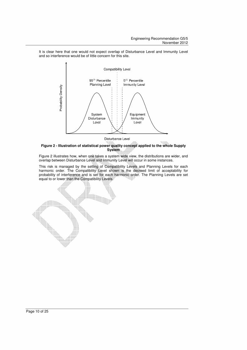
It is clear here that one would not expect overlap of Disturbance Level and Immunity Level and so interference would be of little concern for this site.
Figure 2 - Illustration of statistical power quality concept applied to the whole Supply System
Figure 2 illustrates how, when one takes a system wide view, the distributions are wider, and overlap between Disturbance Level and Immunity Level will occur in some instances.
This risk is managed by the setting of Compatibility Levels and Planning Levels for each harmonic order. The Compatibility Level shown is the decreed limit of acceptability for probability of interference and is set for each harmonic order. The Planning Levels are set equal to or lower than the Compatibility Levels.

Engineering Recommendation G5/5 November 2012
Page 11 of 25
3 Harmonic Voltage Distortion Levels Planning and compatibility levels for all voltage levels are given in Table 1 through Table 10. This Engineering Recommendation does not contain provisions for DC current emissions because of their deleterious effects on the supply system. All DC emissions are deprecated.
3.1 Planning Levels
Table 1 provides the THD planning Levels for LV, MV, HV and EHV systems. Table 2 through to Table 5 provides the planning levels for Harmonic Voltage Distortion in LV, MV, HV and EHV systems respectively.
Table 1: THD Planning Levels
Nominal Voltage THD [%V1]
LV 5% MV 4% HV 3% EHV 3%
Table 2: Planning Levels for Harmonic Voltages in LV Systems
Odd harmonics (non-multiple of 3)
Odd harmonics (multiple of 3)
Even harmonics
Order 'h' Harmonic
voltage [%] Order 'h'
Harmonic voltage [%]
Order 'h' Harmonic
voltage [%]
5 4.0 3 4.0 2 1.6 7 4.0 9 1.2 4 1.0 11 3.0 15 0.3 6 0.5 13 2.5 21 0.2 8 0.4 17 1.6 >21 0.2 10 0.4 19 1.2 12 0.2 23 1.2 >12 0.2 25 0.7
>25 0.2+0.5(25/h)
Table 3: Planning Levels for Harmonic Voltages in MV Systems
Odd harmonics (non-multiple of 3)
Odd harmonics (multiple of 3)
Even harmonics
Order 'h' Harmonic
voltage [%] Order 'h'
Harmonic voltage [%]
Order 'h' Harmonic
voltage [%]
5 3.0 3 3.0 2 1.5 7 3.0 9 1.2 4 1.0 11 2.0 15 0.3 6 0.5 13 2.0 21 0.2 8 0.4 17 1.6 >21 0.2 10 0.4 19 1.2 12 0.2 23 1.2 >12 0.2 25 0.7
>25 0.2+0.5(25/h)
Table 4: Planning Levels for Harmonic Voltages in HV Systems
Odd harmonics (non-multiple of 3)
Odd harmonics (multiple of 3)
Even harmonics
Order 'h' Harmonic
voltage [%] Order 'h' Order 'h'
Harmonic voltage [%]
Order 'h'
5 2.0 3 2.0 2 1.0 7 2.0 9 1.0 4 0.8 11 1.5 15 0.3 6 0.5 13 1.5 21 0.2 8 0.4 17 1.0 >21 0.2 10 0.4 19 1.0 12 0.2 23 0.7 >12 0.2 25 0.7
>25 0.2+0.5(25/h)
Comment [DMJ12]: The voltage levels have been redefined from previous Recommendation G5/4 to include all possible system operating voltages. The voltage levels for LV, HV and EHV are in line with IEC 61000-3-6. The upper range limit for MV is 36kV to account for a 10% operational level for 33kV.
Comment [jmc13]: Do we want to keep this in? Should we give guidance as to where one can limit DC emissions?
Comment [DMJ14]: Subject to Revision based on Work Package 3.
Comment [jmc15]: These were used for 6.6, 11 and 20kV in G5/4. We have used them MV.
Comment [jmc16]: These values were used for >20kV and <145kV in G5/4. We have used them HV.

Engineering Recommendation G5/5 November 2012
Page 12 of 25
Table 5: : Planning Levels for Harmonic Voltages in EHV Systems
Odd harmonics (non-multiple of 3)
Odd harmonics (multiple of 3)
Even harmonics
Order 'h' Harmonic
voltage [%] Order 'h' Order 'h'
Harmonic voltage [%]
Order 'h'
5 2.0 3 1.5 2 1.0 7 1.5 9 0.5 4 0.8 11 1.0 15 0.3 6 0.5 13 1.0 21 0.2 8 0.4 17 0.5 >21 0.2 10 0.4 19 0.5 12 0.2 23 0.5 >12 0.2 25 0.5
>25 0.2+0.5(25/h)
3.2 Compatibility Levels
Table 6 provides the THD compatibility Levels for LV, MV, HV and EHV systems. Table 7 through Table 10 provides the compatibility levels for Harmonic Voltage Distortion in LV, MV, HV and EHV systems respectively.
Table 6: THD Compatibility Levels
Nominal Voltage THD Limit [%V1]
LV 8% MV 8% HV 5% EHV 3.5%
Table 7: Harmonic Voltage Compatibility Levels for LV Systems - from IEC 61000-2-2
Odd harmonics (non-multiple of 3)
Odd harmonics (multiple of 3)
Even harmonics
Order 'h' Harmonic
voltage [%] Order 'h' Order 'h'
Harmonic voltage [%]
Order 'h'
5 6.0 3 1.5 2 1.0 7 5.0 9 0.5 4 0.8 11 3.5 15 0.3 6 0.5 13 3.0 21 0.2 8 0.4 17 2.0 21<h≤45 0.2 10 0.4 19 1.5 10<h≤50 0.25(10/h)+0.25
23<h≤49 2.27(17/h)-0.27
Table 8: Harmonic Voltage Compatibility Levels for MV Systems - from IEC 61000-2-12
Odd harmonics (non-multiple of 3)
Odd harmonics (multiple of 3)
Even harmonics
Order 'h' Harmonic
voltage [%] Order 'h' Order 'h'
Harmonic voltage [%]
Order 'h'
5 6.0 3 1.5 2 2.0 7 5.0 9 0.5 4 1.0 11 3.5 15 0.4 6 0.5 13 3.0 21 0.3 8 0.5 17 2.0 21<h≤45 0.2 10 0.5 19 1.5 10<h≤50 0.25(10/h)+0.25
23<h≤49 2.27(17/h)-0.27
Comment [jmc17]: These were used for just 275kV and 400kV in G5/4. We have used them for EHV in G5/5.
Comment [DMJ18]: Subject to Revision based on Work Package 3.
Comment [DMJ19]: I think we should remove reference to IEC
Comment [jmc20]: This has been recalculated from 1.76 to 1.50 as G5/4 at 19
th harmonic is
above EN 50160.
Comment [jmc21]: These values were defined up to 36.5kV by IEC. We have defined them up to 36kV.
Comment [DMJ22]: I think we should remove reference to the IEC
Comment [jmc23]: This has been recalculated from 1.76 to 1.50 as G5/4 at 19
th harmonic is
above EN 50160.

Engineering Recommendation G5/5 November 2012
Page 13 of 25
Table 9: Harmonic Voltage Compatibility Levels for HV Systems
Odd harmonics (non-multiple of 3)
Odd harmonics (multiple of 3)
Even harmonics
Order 'h' Harmonic
voltage [%] Order 'h' Order 'h'
Harmonic voltage [%]
Order 'h'
5 4.0 3 2.0 2 1.0 7 2.0 9 1.0 4 0.8 11 1.5 15 0.3 6 0.5 13 1.5 21 0.2 8 0.4 17 1.0 >21 0.2 10 0.4 19 1.0 12 0.2 23 0.7 >12 0.2 25 0.7
>25 0.2+0.5(25/h)
Table 10: Harmonic Voltage Compatibility Levels for EHV Systems
Odd harmonics (non-multiple of 3)
Odd harmonics (multiple of 3)
Even harmonics
Order 'h' Harmonic
voltage [%] Order 'h' Order 'h'
Harmonic voltage [%]
Order 'h'
5 3.0 3 1.7 2 1.0 7 1.5 9 0.5 4 0.8 11 1.0 15 0.3 6 0.5 13 1.0 21 0.2 8 0.4 17 0.5 >21 0.2 10 0.4 19 0.5 12 0.2 23 0.5 >12 0.2 25 0.5
>25 0.2+0.3(25/h)
Comment [jmc24]: These values were just defined for 66 and 132kV only. We have defined them for HV.
Comment [jmc25]: These values were just defined for 275 and 400kV only. We have defined them for EHV.
Comment [EP26]: Upper DC injected limit of 0.25% of total rated output AC current of SSEG ‘system’ has been concluded. This limit was 5mA DC per SSEG in G77/1 which was then superseded by G83/1 and it seems that safety factor of 1/2 has been applied.
Comment [jmc27]: SS of WPD For the basis of the DC current emission limits see the ENA DC Injection Working Group report; refer to David Spillet @ ENA. Considerations include transformer noise. See also ‘DCODE G59-2-1 Final (2).pdf’.
Comment [DMJ28]: The Section on DC Emissions has been removed because of insufficient information; This Recommendation already declares DC emissions as problematic.
Deleted: ¶<#>DC Current Emissions¶The effects of, and therefore limits for, DC currents injected in the DNO’s Distribution System is an area under current investigation by DNO’s. Until these investigations are concluded the upper limit for DC injection is 0.25% of AC current rating per phase. 

Engineering Recommendation G5/5 November 2012
Page 14 of 25
4 Assessment of Non-Linear and Resonant Connections The assessment procedure for the connection of non-linear and resonant equipment follows three stages. The objective of this three-stage approach is to balance the degree of detail required by the assessment process with the degree of risk that the connection of the particular installation will result in unacceptable harmonic voltage distortion levels occurring on the network if it is connected without any mitigation measures.
Section 0 provides general guidance on the application of the assessment and associated techniques and methods.
Sections 4.1.6, 4.3 and 4.4 present the process for Stage A, B and C assessments respectively. Figure 3 illustrates the three-stage process with the relevant decisions which affect progress through the three stages.
Figure 3: Three-Stage Assessment Process
Comment [jmc29]: In response to SS comment below, if connection does not meet stage B, then it is then assessed in accordance with stage C.
Comment [jmc30]: SS of WPD Low Voltage equipment does not reach Stage C. For such equipment no connection is possible without mitigation.

Engineering Recommendation G5/5 November 2012
Page 15 of 25
4.1 Guidelines
4.1.1 Point of Evaluation
The Point of Evaluation (POE) is the point on the NOC’s network where the impact of the non-linear or resonant equipment upon harmonic distortion is to be assessed against the planning levels of section 3.1. In most cases the POE will also be also be the PCC. If the assessment results in limits being issued to the customer, the POE is the point where the limits apply. For both Stage A and B the POE is always the PCC. For a Stage A assessment, no limits are issued to the customer and permission to connect is either granted or denied. The current emissions limits resulting from a Stage B assessment are issued at the PCC.
For a Stage C assessment, more than one POE might exist. The PCC will be the first POE at the commencement of the assessment but throughout it may become apparent that other nodes of the NOC’s network require evaluation. This could be due to shifts in resonances modifying existing levels of harmonic distortion or how injected harmonic currents propagate through the network. These remote nodes then become a POE as well as the PCC.
4.1.2 System Impedance
Assessment connections under Stages A, B and C require the harmonic system impedance at the PCC to be taken into consideration through calculation of the system fault level. The system impedance at a particular frequency is needed in order to calculate the resulting harmonic voltage distortion developed at a given node due to the connection of non-linear or resonant equipment.
For both Stage A and B assessments, the short circuit power at the PCC is required. In order to calculate the maximum harmonic voltage distortion, the minimum short circuit power shall be used as this corresponds to the maximum system impedance. For Stage C assessments, detailed harmonic impedance models are required and shall be represented with minimal simplification.
For all stages of assessment, the calculation of the system harmonic impedances shall consider relevant planned outages and various generation and demand backgrounds.
4.1.3 Aggregation and Diversity
When assessing a connection of multiple non-linear equipments, it is sensible to aggregate the harmonic current emissions. If linear addition of the harmonic current emissions from the non-linear equipment results in the criteria of Stage A or B not being met, it is prudent to consider the diversity of operation of the non-linear equipment with the use summation exponents in Table 11 and Equation (3).
Table 11: Summation Exponents
Exponent α Harmonic Order
1.0 h<5
1.4 5≤h≤10
2.0 h>10
∑=i
hih UU )(α
α (3)
The exponent α is chosen on the basis of the expected average phase angle between the harmonic sources. An exponent of 1 implies they are in phase (angle 0°), whilst an exponent of 2 implies they are at 90°. An exponent of 1.4 implies an angle in the region of 70°.
These are to be adopted when knowledge of the operation of the various equipments is known and realistic assumptions can be made about the addition of the harmonic emissions.
Comment [DMJ31]: A schematic showing the difference between the POE and PCC will be inserted.

Engineering Recommendation G5/5 November 2012
Page 16 of 25
4.1.4 Uncertainty
Each assessment will have inherent uncertainty associated with it which can affect the outcome and any limits imposed on a connection. Due diligence is required to ensure such uncertainties are acknowledged and minimised throughout the assessment. Such uncertainties exist within the:
� Modelling of the NOC’s network and the non-linear and resonant connection, which
will affect the calculated resonances in the model;
� Absence of data; and
� The measurement of background harmonic distortion.
Where necessary, derived values or data may be used in lieu of actual data so as to better inform the assessment and limit the uncertainty. Such approaches are particularly useful for deriving values of background harmonic voltage distortion at sites from which measurements are unavailable using data obtained from adjacent sites and system impedance modelling.
4.1.5 Measurement
General Harmonic measurements of the existing levels of distortion on the network form part of both Stage B and Stage C assessments in order to calculate the available headroom for new connections. Stage B measurements are required to be made at the PCC, whilst under Stage C, measurements are required to be made at the PCC and at nodes deeper within the network. These nodes could be at any voltage level and on networks not owned by the NOC. The selection of these remote nodes will be dependent upon the outcome of system studies identifying problematic transfer gains. It is recommended that harmonic measurements be carried out prior to and post energisation of the connection of the non-linear or resonant plant. This will aid compliance monitoring and ensure harmonic emission limits imposed on the connection are met. It is beyond the scope of this recommendation to give procedural details on performing measurements. Guidance on making harmonic measurements is given in International Standard IEC 61000-4-30 [5]. Since the defined accuracy of a Class A power quality monitor according to IEC 61000-4-30 is limited to 0.1%, no measured value can be presented as lower than 0.1%. Therefore, where measured values are either negligible or beyond the scope of the monitor, the values shall be rounded up to 0.1% across all harmonic orders, sub- and inter-harmonics. Transducers Voltage and current transducers are necessary when performing harmonic measurements at voltages above LV; for LV it is possible to connect measuring devices directly. Voltage transducers are typically voltage transformers which form part of protective relay circuits or meter circuits. Such VTs available are of the electromagnetic (wound) type, capacitive divider type and resistive voltage divider type. All transformers have their limitations in terms of frequency response and careful consideration needs to be given to the selection of VT. It is generally accepted that electromagnetic VTs have a frequency response up to one kilohertz and resistive voltage dividers up to hundreds of kilohertz. The lower capacitor unit of the capacitor divider type generally comprises a parallel inductance, which overall gives an arrangement tuned to 50Hz. This arrangement is not suitable for harmonic measurements. However, capacitor divider types can be modified with CTs in such a way as to extend the harmonic frequency response up to tens of kilohertz when necessary. It should be noted that the burden placed on the transformer secondary will affect the overall VT accuracy.
Comment [jmc32]: Need a paragraph on CTs after this one.

Engineering Recommendation G5/5 November 2012
Page 17 of 25
Instrumentation Instruments for harmonic measuring are usually power quality monitors. For harmonic measurements IEC 61000-4-30 [5], which makes reference to the algorithm described in IEC 61000-4-7 [6], details two classes of accuracy for instrumentation measuring harmonic components; these are Class A and B. For the purpose of connection assessment and compliance monitoring it is recommended for the NOC to adopt a Class A device for harmonic measuring and post-commissioning monitoring. Based on IEC 61000-4-30, a 3 second and 10 minute characteristic should be measured, depending on the continuity of the connection’s emissions. These values can then be used as appropriate when assessing the potential impact of any new item of non-linear equipment to be connected. The 95% value from the cumulative probability function should be used in the assessment process. Temporal and Seasonal Variation Levels of harmonic distortion on transmission and distribution networks vary over a 24 hour period, and between weekdays and weekends. It is important that measurements be taken over a contiguous period of at least seven days, and in multiples of seven days i.e. 14, 21, etc. Where possible and practicable, winter peak and summer minimum demand periods should be evaluated to cater for seasonal variation.
4.1.6 Non-Continuous Harmonic Distortion Limits
Short-Duration Bursts and Fluctuating Harmonic Distortion
Non-continuous loads which have either short-duration bursts or fluctuations shall be considered by selecting a more appropriate averaging period. Suitable averaging periods which might be selected include three seconds, one minute and ten minutes.
With respect to the affect of short duration effects on harmonic voltage distortion, compliance shall be assessed with reference to the compatibility levels for individual harmonic orders presented in Section 3.2, adjusted according to Equation (4), and with a corresponding increase in the THD compatibility level of 11%.
45/)5(7.03.1 −+= hk (4)
Sub-Harmonic and Inter-harmonic Distortion
Contingent upon the connection being compliant with ER P28 for flicker [7], if the predicted sub-harmonic and inter-harmonic voltage emissions from an item of equipment or aggregate load are less than 0.1% of the fundamental voltage, connections may be made without any further assessment.
In the United Kingdom, it is assumed that ripple control systems are not being used and therefore a customer’s load, having individual sub- or inter-harmonic emissions less than the following Table 12 limit values, may be connected without assessment.
Table 12: Sub- and Inter-Harmonic Emission Limits
Frequency [Hz] ≤80 ≥90
IHD [%V1] 0.2 0.5
Limits for particular inter-harmonic frequencies between 80 and 90 Hz may be interpolated linearly from the limits given in Table 12.
Comment [DMJ33]: This corresponds to the guidance in IEC 61000-2-12

Engineering Recommendation G5/5 November 2012
Page 18 of 25
Notching
Voltage notching occurs during rectifier commutation when two phases of the supply are effectively short-circuited. Figure 4 illustrates a typical voltage characteristic exhibiting commutation notching.
Figure 4: An Explanation of Voltage Notching
Equipment that results in voltage notching can only be connected if the level of harmonic distortion present at the PCC on the supply system is less than the appropriate planning level. The additional requirements at the PCC shall be:
� The notch depth, d , shall not exceed 15% of the nominal fundamental peak voltage;
� The notch duration, in seconds, shall not exceed:
nomV
dt
71023.2
−×
= (5)
� The peak amplitude of oscillations, due to commutation at the start and at the end of the notch, shall not exceed 10% of the nominal fundamental peak voltage.
As a short duration effect, the affect of notching on harmonic voltage distortion shall follow the same guideline as presented in Equation (4) above.
Comment [DMJ34]: This has been derived using ER G5/4 Limits and the Guidance of IEEE519 on notch area using curve fitting.

Engineering Recommendation G5/5 November 2012
Page 19 of 25
4.2 Stage A
The Stage A assessment applies to all installations, including individual items of plant and equipment and groups of plant and equipment defined by their aggregated effect.
Stage A applies to installations to be connected to a PCC where the following condition would remain valid after said connection:
%8.0≤∑
sc
plant
S
S or %8.0≤
×∑sc
nlrplant
S
WS (6)
Where: plantS represents the capacity of each connection to the PCC,
nlrplantS represents the capacity of each non-linear or resonant plant or equipment connected to
the PCC as either an individual item or as part of a group, W represents a weighting factor for each type of equipment defined in Table 13, and
scS represents the short-circuit power at the Point of Common Coupling
Table 13: Weighting Factors for Various Types of Plant and Equipment [9]
Equipment Type Typical Current Waveform
Typical Current THD Weighting Factor
Single Phase Power Supply (Rectifier and Smoothing Capacitor)
80% with high 3rd 2.5
Semi-Converter
High 2nd
, 3rd and 4
th at
partial loads 2.5
6-Pulse Converter, Capacitive Smoothing, No Series Inductance
80% 2.0
6-Pulse Converter, Capacitive Smoothing, Series Inductance > 3%; DC Drive
40% 1.0
6-Pulse Converter, Large Inductor
28% 0.8
AC Voltage Regulator
Varies with firing angle 0.7
12 Pulse Converter
15% 0.5
Large Capacitive Element: HV/EHV Cable, PFC, Harmonic Filter
N/A 2.0
Other
N/A 2.5
Comment [DMJ35]: The value of 08% is indicative and is based on the individual connection limit in IEC 61000-3-2 and IEC 61000-3-12 of 0.2% and its original basis of four connection per PCC. This method, as opposed to just the IEC method, prevents successive connections from leading to planning level breaches because the amount of non-linear and resonant capacity becomes a defining factor not just the singular connection under question.
Comment [DMJ36]: IEC 61000-3-6 references a resonance multiplier of 2 (Section 8.1.1 Page 26), which is the basis of this indicative value.

Engineering Recommendation G5/5 November 2012
Page 20 of 25
All equipment and plant shall be permitted connection without further consideration contingent upon the condition presented in Equation (6) being met and the relevant condition below being met:
� For LV installations with aggregate ratings of less than 16 A, the installation shall be compliant with IEC 61000-3-2 [8];
� For LV installations with aggregate ratings of between 16 A and 75 A, the installation shall be compliant with IEC 61000-3-12 [4];
� For other installations, and for LV installations with aggregate ratings above 75 A, the harmonic current emissions shall be below those calculated using Equation (7); or
� For resonant plant at all voltage levels without harmonic current emissions, no further criterion is applicable.
sc
r
lpl
h IK
KVI = (7)
Where: hI represents the harmonic current per phase in Amperes for the harmonic order h ,
rK represents the resonant factor equal to:
LV: for 7≤h , 0.1=rK MV: for 8≤h , 0.2=rK
for 7>h , 5.0=rK for 8>h , 0.1=rK
lK represents a limit factor according to Table 14,
plV represents the planning level for the harmonic order h , and
scI represents the short-circuit current at the PCC derived as
nomV
scS
scI
×
=
3
Table 14: Limit Factors for Equation (7)
Order Factor Order Factor Order Factor Order Factor
26 0.25 51 0.05 76 0.09 2 1.25 27 0.09 52 0.13 77 0.09 3 0.83 28 0.24 53 0.12 78 0.03 4 0.63 29 0.23 54 0.05 79 0.08 5 0.50 30 0.08 55 0.12 80 0.08 6 0.42 31 0.21 56 0.12 81 0.03 7 0.94 32 0.21 57 0.04 82 0.08 8 0.83 33 0.08 58 0.11 83 0.08 9 0.28 34 0.19 59 0.11 84 0.03 10 0.66 35 0.19 60 0.04 85 0.08 11 0.60 36 0.07 61 0.11 86 0.08 12 0.21 37 0.18 62 0.11 87 0.03 13 0.51 38 0.17 63 0.04 88 0.08 14 0.47 39 0.06 64 0.10 89 0.07 15 0.17 40 0.17 65 0.10 90 0.03 16 0.41 41 0.16 66 0.04 91 0.07 17 0.39 42 0.06 67 0.10 92 0.07 18 0.14 43 0.15 68 0.10 93 0.03 19 0.35 44 0.15 69 0.04 94 0.07 20 0.33 45 0.06 70 0.09 95 0.07 21 0.12 46 0.14 71 0.09 96 0.03 22 0.30 47 0.14 72 0.03 97 0.07 23 0.29 48 0.05 73 0.09 98 0.07 24 0.10 49 0.13 74 0.09 99 0.03 25 0.26 50 0.13 75 0.03 100 0.07
Comment [DMJ37]: Stage A has been made applicable to other voltage levels as well because Section 7.4.2 of ER G5/4-1 is essentially the same as a Stage A with the exception that it refers to Table 12 of ER G5/4-1 as opposed to an IEC 61000 standard. Thus they were conceptually the same, and should be grouped together by concept as opposed to voltage level. Futhermore, IEC 61000-3-6 also allows for HV and EHV connections to be assessed simply.
Comment [DMJ38]: This formula, along with the associated Table 12, has been developed from first principles and provides a more appropriate format applicable to more scenarios.
Comment [DMJ39]: The same principle as for ER G5/4-1 is followed insofar as linear
addition is used for h≤5 and triplens; and quadrature addition is used for all other harmonic orders.

Engineering Recommendation G5/5 November 2012
Page 21 of 25
4.3 Stage B
A stage B assessment is indicated for LV and MV connections when the criteria of a Stage A assessment are not met and the background harmonic voltage distortion levels are likely to be considerable. Stage B follows a simple calculation which involves:
� Determining the modified background harmonics and apportioning the available headroom according to the capacity of the connection under question, and
� Calculating the effect of the connection based on the equipment characteristics, as declared by the equipment manufacturer, and using a linearised impedance model as used in Stage A.
4.3.1 Estimation of the Connection Headroom
With consideration to the guidelines on measurement provided in Section 4.1.5, the Network Owner shall obtain measurements of harmonic voltage distortion at the PCC from which the total remaining headroom for each harmonic order shall be calculated according to:
h
bg
h
pl
h
totalhr VVV −=− for harmonic orders subject to linear addition, and (8)
( ) ( )22 h
bg
h
pl
h
totalhr VVV −=−
for harmonic orders subject to quadratic
addition
(9)
Where: h
totalhrV−
represents the headroom (remaining) harmonic voltage distortion for harmonic h ,
h
plV is the harmonic voltage distortion planning level for harmonic h , defined in Section 11, and
h
bgV is the measured background harmonic voltage distortion for harmonic h .
Linear addition in accordance with Equation (8) is applicable to:
� All orders less than or equal to five,
� All triplens, and
� Other site-specific problematic harmonic orders.
The quadratic addition of Equation (9) is applicable to all other orders.
Once the total remaining headroom has been determined, the headroom available to the connection shall be calculated according to Equation (10).
capacity
nlrplanth
totalhr
h
hrS
WSVV
×=
− (10)
Where: capacityS represents the connection capacity at the PCC.
This provides a connection-related headroom profile which prejudices neither the present, nor the possible future connections at the PCC, whilst considering the effects of the existing connections. This profile shall be considered as a guideline to the Network Owner; the ultimate decision as to the suitability of a connection rests with the Network Owner. The Network Owner may adjust this profile, subject to the following limitations:
� Where background levels are below planning levels, the headroom profile shall not lead to a breach of the planning levels,
� Where background levels are above planning levels, the profile shall be limited to 0.1%, and
� Where the calculated value falls below 0.1%, the value shall be raised to 0.1%.

Engineering Recommendation G5/5 November 2012
Page 22 of 25
4.3.2 Calculation of Connection Limits
Having determined the harmonic voltage distortion which may be associated with the new connection, a two-step calculation is necessary in order to:
� Determine the effect of the connection on the existing harmonic distortion (which is of particular importance for Resonant Plant), and
� Determine the current emission limits with which the connection must comply in order for the connection to qualify under a Stage B assessment.
The connection of Resonant Plant can magnify existing background harmonic beyond the available connection headroom. Equation (11) provides a simple means of approximating this magnification.
rr h
hr
h
bg
PCC
cscVV
P
QS<× by at least 0.1% (11)
Where: cQ is the reactive power of the resonant plant,
rh is the resonant order, equal to cQscS
PCCP is the active power delivered at the PCC, excluding that from the present connection,
rh
bgV if the background measurement for the resonant order rh , and
rh
hrV is the connection headroom calculated for the resonant order rh according to Equation (10).
A characteristic of this equation is that lower order resonances are more likely to not satisfy this equation whilst higher order resonances are. Therefore, the connection of small or lower voltage resonant plant will qualify under this Stage B criterion.
Where a connection contains both Resonant and Non-Linear Plant, Equation (11) shall be used to reduce the available headroom at the resonant harmonic order for use in the following determination of current emissions limits. The available headroom at the resonant harmonic order is equal to the amount by which the left-hand side of Equation (11) is less than the right-hand side, and shall not be less than 0.1%, as indicated above.
The available connection headroom is now used in combination with a linear harmonic impedance approximation according to Equation (12) to determine the current emission limits according to Ohm’s law in Equation (13).
sc
nom
r
h
S
VhKZ
2
= (12)
h
h
hrh
Z
VI = (13)
Where: cQ is the reactive power of the resonant plant,
rh is the resonant order, equal to cQscS
PCCP is the active power delivered at the PCC, excluding that from the present connection,
rh
bgV if the background measurement for the resonant order rh , and
rh
hrV is the connection headroom calculated for the resonant order rh according to Equation (10).
A connection shall be permitted, without further consideration, if the conditions in Equations (11) and (13) are satisfied for Resonant and Non-Linear Plant Equipment respectively.
Comment [DMJ40]: This equation has been developed from first-principles as an approximation to the modification and includes the effect of load (PCC) load which provides damping.

Engineering Recommendation G5/5 November 2012
Page 23 of 25
4.4 Stage C
This final stage of assessment is applicable when the calculations of a Stage B assessment indicate that either a resonant condition exists which jeopardises compliance or the emissions of the connection installation exceed those calculated using a simplistic model of the system and plant characteristics. Stage C requires detailed modelling of both the system and the connected installation in an effort to more accurately predict the affect of the connected installation on the system.
The assessment of the connection under Stage C involves:
1. Identifying remote electrical nodes which might be affected by the connection of the installation, either by the propagation of harmonic emissions or by the modification of the system harmonic impedances;
2. Measurement of the background harmonic voltage distortion at the PoE (and PCC where different) and at these remote nodes as appropriate and practicable;
3. Calculation of the headroom available to the connection according to Section 4.3.1;
4. Calculation of the modification to the background harmonic voltage distortion resulting from the expected change in system harmonic impedances with the new connection energised and operating;
5. Calculation of the incremental (additional) harmonic voltage distortion impressed on the system by the harmonic emissions of the connection; and
6. Prediction of the resultant harmonic voltage distortion through the system by an addition of the modified background harmonic voltage distortion levels and the incremental harmonic voltage distortion levels in the preceding calculations 4 and 5 respectively. For the purposes of addition, the criteria for the use of linear and quadratic addition shall follow the same principle defined in Section 4.3.1.
The connection of the installation is acceptable if the result of the predicted resultant harmonic voltage distortion levels is below the connection headroom calculated according to Section 4.3.1.
5 Conclusion In support of the Electromagnetic Compatibility Regulations 2006 [1], this Recommendation sets out the good practice for the limitation of harmonic voltage disturbance on the public supply systems in the United Kingdom.
This is achieved through the definition of Planning and Compatibility limits for all power system voltage levels and a suitable three-staged procedure for the assessment of the impact of equipment connections to the supply system.
Both non-linear and resonant plant connections are considered: non-linear plant because of their associated harmonic emissions and resonant plant because of the shift in network resonances which might result in non-compliance if not assessed.

Engineering Recommendation G5/5 November 2012
Page 24 of 25
References
Directives and Regulations
[1] The Electromagnetic Compatibility Regulations 2006, Statutory Instrument 2006 No. 3418
[2] DIRECTIVE 2004/108/EC OF THE EUROPEAN PARLIAMENT AND OF THE COUNCIL, 15
December 2004
Harmonised Standards
[3] Voltage Characteristics of Electricity Supplied by Public Distribution Networks,
BS EN 50160:2010, 31 August 2010, ISBN: 978-0-58074103-6, British Standards Institution,
389 Chiswick High Road, London W4 4AL, United Kingdom
[4] Electromagnetic Compatibility (EMC) – Part 2-12: Environment – Compatibility levels for low –
frequency conducted disturbances and signalling in public medium-voltage power supply
systems, IEC 61000-2-12:2003, International Electrotechnical Commission, 3 rue de
Varembé, P.O. Box 131, CH - 1211 Geneva 20, Switzerland
[5] Electromagnetic Compatibility (EMC) – Part 4-30: Testing and measurement techniques –
Power quality measurement methods, IEC 61000-4-30:2003, International Electrotechnical
Commission, 3 rue de Varembé, P.O. Box 131, CH - 1211 Geneva 20, Switzerland
[6] Electromagnetic Compatibility (EMC) – Part 4-7: Testing and measurement techniques –
General guide on harmonics and interharmonics measurements and instrumentation, for
power supply systems and equipment connected thereto, IEC 61000-4-7:2002, International
Electrotechnical Commission, 3 rue de Varembé, P.O. Box 131, CH - 1211 Geneva 20,
Switzerland
[7] Planning Limits for Voltage Fluctuations Caused by Industrial, Commercial and Domestic
Equipment in the United Kingdom, Engineering Recommendation P28:1989, Energy
Networks Association, 18 Stanhope Place, Marble Arch, London W2 2HH, United Kingdom
[8] Electromagnetic Compatibility (EMC) – Part 2-2: Environment - Compatibility levels for low-
frequency conducted disturbances and signalling in public low-voltage power supply systems,
IEC 61000-2-2:2002, International Electrotechnical Commission, 3 rue de Varembé, P.O. Box
131, CH - 1211 Geneva 20, Switzerland
[9] Electromagnetic Compatibility (EMC) – Part 3-6:Limits – Assessment of emission limits for the
connection of distorting installations to MV, HV and EHV power systems, IEC 61000-3-
6:2008, International Electrotechnical Commission, 3 rue de Varembé, P.O. Box 131, CH -
1211 Geneva 20, Switzerland
Engineering Recommendation G5/5 November 2012
Page 25 of 25
Appendix A: Example of a Stage A Assessment An example shall be developed in due course.
Appendix B: Example of a Stage B Assessment An example shall be developed in due course.
Appendix C: Example of a Stage C Assessment An example shall be developed in due course.