engineering report - detroit river international crossing project€¦ · ·...
TRANSCRIPT


Detroit River International Crossing Engineering Report
Volume 4: Interchange Structure Study Page 1
S07 of 82194 JN 802330
Springwells Avenue over I-75 Structure Study
General The purpose of this study is to investigate different structure types for the replacement of the Springwells Avenue Bridge over I-75. The Springwells Avenue Bridge requires replacement due to realignment of Springwells Avenue, the northbound and southbound service drives and the revised I-75 lane configuration due to the proposed Detroit River International Crossing (DRIC) Plaza Ramps. The existing structure carries 4 lanes of traffic accommodating bi-directional movement along Springwells Avenue over I-75 (12’ inner lanes and 17’-0” outer lanes). A single 17’-9” Service Drive U-turn lane, on the east side of the bridge, accommodates movements from the northbound and southbound service drives. This lane is separated from the Springwells Avenue traffic by a 10’ wide median. A 10’ wide sidewalk exists on the west side of the bridge. A 1’-9” brush block with a concrete parapet and bridge railing is present along the east edge of the bridge and a 1’-0” concrete parapet with a bridge railing and pedestrian fencing is present along the west edge of the bridge. The out-to-out deck width of the existing structure is 98’-8 ½”. The bridge crosses I-75 on a skewed alignment to join Springwells Avenue, north of I-75 with West End Avenue south of I-75. The structure is a four span rolled steel beam structure with a 9” reinforced concrete deck. The span lengths are 64’-3 1/16”- 83’-4 ¼” – 83’-4 ¼”– 72’-0 7/16”. Top and bottom flange cover plates are located over the center pier. Pin and link hangers support the end spans at the exterior pier locations. The substructure consists of cap and column piers and stub abutments. Lightweight backfill was used behind the existing abutments because of poor soil conditions. All substructure units are founded on 60 ton cylindrical piles. The front row of the existing abutment piles have been driven at a 1H:3V batter. All existing pier piles have been driven vertically. There are concrete struts, under I-75 roadway, between the existing piers to resist lateral loads. The new alignment of Springwells Avenue crosses I-75 at approximately a 0o skew. The proposed bridge will also carry 4 lanes of Springwells traffic (12’ inner lanes and 14’ outer lanes). A 20’ Service Drive U-turn lane is proposed along the east side of the bridge. It is separated from through traffic by a 10’ median. The median also functions as a sidewalk to handle pedestrian traffic. A 10’ sidewalk is proposed on the west side of the bridge. A 1’-6” concrete parapet, with a bridge railing and pedestrian fencing is proposed along both the west and east sides of the bridge. The out-to-out deck width of the proposed structure is 95’-3”. Springwells Avenue is posted 25 MPH and designed for 30 MPH traffic. Therefore, 2’ wide shy distances are provided between the through lanes and the median/sidewalk. See the General Plan of Site Plan and Cross Sections in Appendix A for details and geometry. The structure design is to be completed based on current AASHTO LRFD specifications. The design live load is the AASHTO HL-93 Modified used by MDOT. Replacement of the Springwells Avenue Bridge is to be coordinated with the planned improvements to the I-75 ramp alignments, the service drive work and the realignment of Springwells Avenue. The structure requires replacement do to the realignment of Springwells Avenue, the realignment of the north and south service roads and modifications to the I-75 ramps. Currently, geotechnical information is not available for the bridge. From the existing soil information it seems that there is soft clay for approximately 70 feet below the existing pile caps. Preliminary soils investigations propose that a lightweight fill, Expanded Polystyrene (EPS) blocks be placed as backfill behind the abutments. The use of EPS blocks will minimize settlement of the bridge approach pavement and reduce
the lateral earth pressure on the high wall abutment allowing the lateral earth pressure to be resisted by the pile batter and not depend on the stiffness of the soil below the footing. Additional soil borings and the geotechnical report will confirm the backfill and foundation assumptions used to compute the preliminary cost of the structure. The high wall abutments will be supported on piles. The front row of piles will be battered to resist the lateral loads. The proposed pier is located in the I-75 median at the existing Pier 2 location. The existing piles may be reused and supplemented with additional battered piles, driven between existing piles to resist lateral loads. The use of semi-integral or independent back wall with sliding approach slabs abutments can be investigated during preliminary design to eliminate expansion joints on the bridge. Under Clearance and Grade Raise The existing structure currently has a minimum vertical under clearance of 15’-8” based on the vertical under clearance posted on the bridge. I-75 at the project location is considered a special route. In this case, a 14’-9” minimum under clearance is required for the proposed bridge. Currently, the I-75 roadway is posted for 55 MPH; however, based on the current vertical geometry, the roadway is designed for 50 MPH. MDOT has requested that the preferred alignment for the Detroit River International Crossing (DRIC) accommodate a 60 MPH design speed on I-75, so that I-75 can be upgraded with future improvements to a 60 MPH design speed. Therefore, the vertical profile was set at 15’-3” to account for these future modifications to the I-75 vertical geometry. The following characteristics of the proposed road and bridge design affect the underclearance:
1. Springwells Avenue is being realigned. 2. The existing grade on Springwells Avenue is 5.0%. The grade will be improved to 3%. 3. The existing bridge is skewed compounding the problem of improving the grade since the existing total length of
the existing bridge is longer than the proposed. 4. The structure depth has increased slightly due to longer span lengths from the elimination of the piers. 5. Accommodation of future I-75 improvements to upgrade the vertical design speed from 50 MPH to 60 MPH.
The proposed profile currently shown on the General Plan of Site accommodates the expected Springwells Avenue profile grade. A 2.0% deck cross slope is recommended. Maintaining Traffic Springwells Avenue traffic, one lane in each direction, will be maintained during reconstruction of the proposed Springwells Avenue Bridge over I-75. Earth retention will be required to stage the removal of existing abutments and construct the new abutments while maintaining traffic. Due to the abutment height, the earth retention will need to be braced or tied-back with earth anchors. As mentioned earlier, lightweight cellular concrete will be required as backfill behind the abutment. In addition to reducing lateral loads, the cellular concrete will provide a stable base for traffic during staged construction. Traffic control along I-75 for the structure replacement will require shoulder and temporary single lane closures to remove the existing piers and construct the new pier. Temporary freeway closures will be necessary during removal and erection of the beams.

Detroit River International Crossing Engineering Report
Volume 4: Interchange Structure Study Page 2
Structure Options Three superstructure alternatives were investigated in this study:
• 39” Spread PPC Box Beam • 39” Side-by-Side PPC Box Beam • 34’ Web Steel Plate Girder
Two-span arrangements with full-height abutments were considered for the three alternatives listed above. See Appendix A for the span arrangement and cross sections of the alternatives listed above. Preliminary beam design was completed for each superstructure type utilizing AASHTO LRFD, 2007 Edition as directed by MDOT. The MDOT HL-93 Modified loading was used for the design loading for each alternative. A single span option was not investigated based on the significant increase in construction depth required and the limited increase available due to the vertical geometric constraints of the nearby service drives. The 39” Spread PPC Box Beam Alternative will result in a slightly deeper construction depth than the 39” Side-by-Side PPC Box Beam or the 34” Web Steel Plate Girder Alternatives. However, the greater construction depth will have a negligible impact to the Springwells Avenue profile and will not impact the adjacent service drive intersections with Springwells Avenue. Cost The cost for the 39” Spread PPC Box Beam Alternative is less than the cost for the 39” Side-by-Side PPC Box Beam or the 34” Web Steel Plate Girder Alternatives. Cost estimates for each alternative are included in Appendix B. The cost estimates assume full-height cantilever abutments supported on piles. The median pier is a multi-column concrete pier supported on piles. Geotechnical investigation will need to confirm these recommendations. The following is a cost comparison between the different alternatives: Alternative Superstructure
Depth Total Cost Cost/SF Deck
39” Spread PPC Box Beam 52” $ 4,447,800 $240
39” Side-by-Side PPC Box Beam 48” $5,015,880 $279
34” Web Steel Plate Girder 44” $ 5,456,670 $308
The costs shown are for the bridge only and do not include approach cost associated with raising the Springwells Avenue profile. The Total Cost includes the removal of the existing structure. The Cost/SF does not include removal of the existing structure. Also, a 15% design contingency has been added to costs above.
Utilities Several utilities are attached to the Springwells Street structure. PLD conduits are located in the west sidewalk and the median of the existing structure. These conduits feed the street lighting masts located on sidewalk and median. A 12” gas main is located below the deck under the west sidewalk. 12-4” diameter Detroit Edison ducts are supported by diaphragms under the northbound lanes, 6-4” diameter PLD ducts are supported on diaphragms under the median. These 6 ducts are encased with concrete and carry live electric service with voltage between 110 and 220 volts. Relocation of the gas main will be required prior to construction. If the relocation of this gas main is restricted based on seasonal usage this information will be provided to the contractor in the specifications for coordination during construction. The spread box beam alternative can accommodate the relocation of all the existing utilities by supporting the utilities from the underside of the deck between the beams. The Detroit Edison Conduits and PLD ducts can be embedded in the sidewalk or median. The gas main would need to be relocated off the structure if the side-by-side box beam alternative was used. Bridge lighting conduits can be placed in the concrete parapet or the raised median, depending on the location of the street lighting. The location of the lighting will be investigated during preliminary design. Drainage It is assumed that drainage will be collected off the bridge on the roadway and scuppers will not be required on the bridge based on the following:
1. The tributary width of bridge deck is relatively small. 2. The longitudinal grades are relatively steep. 3. Scuppers are not present on the existing bridge, which has a longer total span length and a wider pavement
than the proposed bridge. Aesthetics Aesthetic treatments, including concrete texturing of the concrete parapet and concrete surface coating, are anticipated for the proposed structure. The aesthetic treatment can be accommodated by both alternatives and will have approximately the same cost. The limits of the texturing are unknown at this time. However, an aesthetic cost equaling 1% of the bridge cost was included in the Preliminary Cost Estimate for all bridges. Any specific aesthetic requirements are to be determined by MDOT through the Context Sensitive Solutions (CSS) process with the public and in consultation with the City of Detroit and will be incorporated into the Final Design plans. Recommendations Based on estimated costs the 39” Spread PPC Box Beam Alternative is the recommended alternative for the Springwells Avenue Bridge over I-75. Also, the recommended alternative will accommodate the existing 12” diameter gas main attached to the existing Springwells Avenue Bridge.

Detroit River International Crossing Engineering Report
Volume 4: Interchange Structure Study Page 3
S08 of 82194 JN 802330 Green Avenue over I-75
Structure Study General The purpose of this study is to investigate different structure types for the replacement of the Green Avenue Bridge over I-75. The preferred alignment of the Detroit River International Crossing (DRIC) Project requires reconfiguration of the existing I-75 interchange at Livernois/Dragoon. The Northbound and Southbound I-75 exit ramps are to be relocated and will be located under Green Avenue, which will conflict with the existing piers. The existing structure carries 2 through lanes in each direction (44’ face-to-face curb), two 10’ sidewalks, and a 1’-0” concrete barrier with a bridge railing and pedestrian fencing along each side of the bridge. The out-to-out width of the existing bridge is 66’-5”. Intersections with the Northbound and Southbound Service Drives are present south and north of the bridge. The existing superstructure is four spans consisting of 36” Wide Flange rolled steel beam section with an 8” composite reinforced concrete deck. The spans are 68’-10”, 74’-11”, 74’-11” and 68’-10” for a total length of 287’-6”. Top and bottom flange cover plates are located over the center pier. Pin and link hangers support the end spans at the exterior pier locations. The substructure consists of cap and column piers and stub abutments. Lightweight backfill was used behind the existing abutments because of poor soil conditions. All substructure units are supported on 60-ton cylindrical piles. The pier piles are driven vertically. The front row of abutment piles are driven at a 1H:3V batter. There are existing reinforced concrete struts, under I-75 roadway, between the existing piers to resist lateral loads. The alignment of Green Avenue will not change. The proposed bridge will carry two through lanes in each direction (52’ clear roadway width). A 20’ Service Drive U-turn lane is proposed along the east side of the bridge to accommodate the Northbound and Southbound Service Drive traffic movements. The U-turn lane is separated from the through lanes with a 10’ wide raised median. The raised median will function as a sidewalk to handle the pedestrian traffic. A 10’ sidewalk is proposed on the west side of the bridge. 1’-6” concrete parapets with bridge railing and pedestrian fencing is present along the west and east sides of the bridge. The proposed structure has an out-to-out deck width of 95’-3”. The proposed bridge will be a two span structure with high wall abutments. The span arrangement will accommodate tapers and standard shoulders for the new plaza ramps. See the General Plan of Site Plan and Cross Sections, in Appendix A for details and geometry. The structure design is to be completed based on current AASHTO LRFD specifications. The design live load is the AASHTO HL-93 Modified used by MDOT. Replacement of the Green Avenue Bridge is to be coordinated with the planned improvements to the I-75 ramp alignments and the service drive work. The structure requires replacement based on the elimination of the exterior columns due to the proposed I-75 ramp modifications. Green Avenue traffic will be detoured during reconstruction of the proposed Green Avenue Bridge. Currently, geotechnical information is not available for the bridge. From the soil information shown on the existing bridge record plans there is soft clay for approximately 70 feet below the existing pile caps. Preliminary soils investigations propose that a lightweight fill, Expanded Polystyrene (EPS) blocks be placed as backfill behind the abutments. The use of EPS blocks will minimize settlement of the bridge approach pavement and reduce the lateral earth pressure on the high wall abutment allowing the lateral earth pressure to be resisted by the pile batter and not depend on the stiffness of the soil below the footing.
Additional soil borings and the geotechnical report will confirm the backfill and foundation assumptions used to compute the preliminary cost of the structure. The high wall abutment will be supported on piles. The front row of piles will be battered to resist the lateral loads. The proposed pier is located in the I-75 median at the existing Pier 2 location. The existing piles may be reused and supplemented with additional battered piles, driven between existing piles to resist lateral loads. High wall abutments are proposed. The use of semi-integral or independent back wall with sliding approach slabs abutments can be investigated during preliminary design to eliminate expansion joints on the bridge. Under Clearance and Grade Raise The existing structure currently has a minimum vertical under clearance of 14’-10” based on the vertical under clearance posted on the bridge. I-75 at the project location is considered a special route. In this case, a 14’-9” minimum under clearance is required for the proposed bridge. Currently, the I-75 roadway is posted for 55 MPH; however, based on the current vertical geometry, the roadway is designed for 50 MPH. MDOT has requested that the preferred alignment for the DRIC accommodate a 60 MPH design speed on I-75, so that I-75 can be upgraded with future improvements to a 60 MPH design speed. Therefore, the vertical profile was set at 15’-3” to account for these future modifications to the I-75 vertical geometry. The following characteristics of the proposed road and bridge design affect the underclearance:
1. The existing vertical clearance is less than 15’-3”. 2. The proposed structure depth increase due to the increased span length. 3. Accommodation of future I-75 improvements to upgrade the vertical design speed from 50 MPH to 60 MPH.
The proposed profile currently shown on the General Plan of Site accommodates the expected Green Avenue profile grade. A 2.0% deck cross slope is recommended. Maintaining Traffic Traffic along Green Avenue traffic will be detoured during the reconstruction of the Green Avenue Bridge. Traffic control along I-75 for the structure replacement will require shoulder and temporary single lane closures to remove the existing pier and abutments and to construct the new pier and abutments. Temporary freeway closures will be necessary during removal of the existing and erection of the new beams. Structure Options Three superstructure alternatives were investigated in this study:
• 42” Spread PPC Box Beam • 39” Side-by-Side PPC Box Beam • 34” Web Steel Plate Girder
Two-span arrangements with full-height abutments were considered for the three alternatives listed above. See Appendix A for the span arrangement of the alternatives listed above.

Detroit River International Crossing Engineering Report
Volume 4: Interchange Structure Study Page 4
Preliminary beam design was completed for each superstructure type utilizing AASHTO LRFD, 2007 Edition as directed by MDOT. The MDOT HL-93 Modified loading was used for the design loading for each alternative. A single span option was not investigated based on the significant increase in construction depth required and the limited increase available due to the vertical geometric constraints of the nearby service drives. The 42” Spread PPC Box Beam Alternative will result in a slightly deeper construction depth than the 39” Side-by-Side PPC Box Beam and 34” Web Steel Plate Girder Alternatives. However, the greater construction depth will have a negligible impact to the Green Avenue profile and will not impact the adjacent service drive intersections with Green Avenue. Cost The cost for the 42” Spread PPC Box Beam Alternative is less than the cost for the 39” Side-by-Side PPC Box Beam and 34” Web Steel Plate Girder Alternatives. Cost estimates for each alternative are included in Appendix B. The cost estimates assume full-height cantilever abutments supported on piles. The median pier is a multi-column concrete pier supported on piles. Geotechnical investigation will need to confirm these recommendations. The following is a cost comparison between the different alternatives: Alternative Superstructure
Depth Total Cost Cost/SF Deck
42” Spread PPC Box Beam 55” $4,207,360 $208
39” Side-by-Side PPC Box Beam 48” $4,523,630 $226
34” Web Steel Plate Girder 51” $5,379,840 $275
The costs shown are for the bridge only and do not include approach cost associated with raising the Green Avenue profile. The Total Cost includes the removal of the existing structure. The Cost/SF does not include removal of the existing structure. Also, a 15% design contingency has been added to costs above. Utilities Several utilities are attached to the Green Avenue Bridge. An existing 12” diameter MichCon Gas main is attached to the structural steel under the southbound lanes of the bridge. Twelve - 4” diameter and a 120kV Detroit Edison conduit are attached to the underside of the deck under the southbound lanes. Four Public Lighting Department (P.L.D.) conduits are attached to the underside of the deck under the east sidewalk. Relocation of the gas main will be required prior to construction. If the relocation of this gas main is restricted based on seasonal usage, this information will be provided to the contractor in the specifications for coordination during construction. The spread box alternative can accommodate the relocation of the existing gas main, while the side-by-
side box beam alternative cannot accommodate the relocation of the gas main, requiring the gas main to be relocated off the bridge. The Detroit Edison Conduits can be accommodated by attaching to the underside of the slab for the spread box beam alternative or can be embedded in the sidewalk for the side-by-side box beam alternative. Bridge lighting conduits can be placed in the concrete parapet or the raised median, depending on the location of the street lighting. The location of the lighting will be investigated during preliminary design. PLD conduits can be can be accommodated by attaching to the underside of the slab for the spread box beam alternative or can be embedded in the raised median for the side-by-side box beam alternative. An abandoned 24” diameter sewer exists under the I-75 pavement at Clark Avenue. Piles for the pier and abutment footings should be spaced to miss this sewer. Drainage It is assumed that drainage will be collected off the bridge on the roadway and scuppers will not be required on the bridge based on the following:
4. The tributary width of bridge deck is relatively small. 5. The longitudinal grades are relatively steep. 6. Scuppers are not present on the existing bridge, which has a longer total span length than the proposed bridge.
Aesthetics Aesthetic treatments, including concrete texturing of the concrete parapet and concrete surface coating, are anticipated for the proposed structure. The aesthetic treatment can be accommodated by all four alternatives and will have approximately the same cost. The limits of the texturing are unknown at this time. However, an aesthetic cost equaling 1% of the bridge cost was included in the Preliminary Cost Estimate for all bridges. Any specific aesthetic requirements are to be determined by MDOT through the Context Sensitive Solutions (CSS) process with the public and in consultation with the City of Detroit and will be incorporated into the Final Design plans. Recommendations Based on costs the 42” Spread PPC Box Beam Alternative is the recommended alternative for the Green Avenue Bridge over I-75. Also, the recommended alternative will accommodate the existing 12” diameter gas main attached to the existing Green Avenue Bridge.

Detroit River International Crossing Engineering Report
Volume 4: Interchange Structure Study Page 5
S10 of 82194 JN 802330 Livernois Avenue over I-75
Structure Study General The purpose of this study is to investigate different structure types for the replacement of the Livernois Avenue Bridge over I-75. The Preferred Alignment of the Detroit River International Crossing (DRIC) Project requires reconfiguration of the existing I-75 interchange at Livernois/Dragoon. The Northbound and Southbound I-75 exit ramps are to be relocated and will be located under Livernois, which will conflict with the existing piers. The existing structure carries 4 (12’ wide) lanes of southbound traffic along Livernois Avenue over I-75. A 10’-wide sidewalk with a 1’-0” concrete parapet, a bridge railing and pedestrian fencing is present along both the west and east sides of the bridge. The out-to-out deck width of the existing structure is 70’-5”. The bridge crosses I-75 on a skewed alignment (approximately 8.5 degrees). Intersections with the Northbound and Southbound Service Drives are present south and north of the bridge. The superstructure consists of a four span rolled steel beam with a 9” composite reinforced concrete deck. The spans are 37’-8 7/8”, 75’-9”, 75’-9”, 37’-8 7/8”. The end spans are W27’s and the interior spans are W36 rolled sections. Top and bottom flange cover plates are located over the center pier. Pin and link hangers support the end spans at the exterior pier locations. The substructure consists of cap and column piers and stub abutments. Lightweight backfill was used behind the existing abutments because of poor soil conditions. All substructure units are supported on 60 ton cylindrical piles. The front row of the existing abutment piles have been driven at a 1H:3V batter. All existing pier piles have been driven vertically. There are existing concrete struts, under the I-75 roadway, between the existing piers to resist lateral loads. The alignment of Livernois Avenue will not change. The proposed bridge will carry one 12’ wide lane in each direction with 12’ wide median left hand turn lane at the each end of the bridge. Service drive U-turn lanes are present along the west and east sides of the bridge to accommodate the Northbound and Southbound Service Drive traffic movements. The U-turn lanes are separated from the through lanes with 10’ wide raised medians. The medians function as sidewalks to handle the pedestrian traffic. The proposed structure has an out-to-out deck width of 103’-5”. Livernois Avenue is posted 25 MPH and designed for 30 MPH traffic. Therefore, 2’ wide shy distances are provided between the through lanes and the medians. See the General Plan of Site Plan and Cross Sections for details and geometry located in Appendix A. The structure design is to be completed based on current AASHTO LRFD specifications. The design live load is the AASHTO HL-93 Modified used by MDOT. Replacement of the Livernois Avenue Bridge is to be coordinated with improvements to the I-75 ramp alignments and the service drive work. The structure requires replacement based on the elimination of the exterior piers due to the proposed I-75 ramp modifications. Currently, geotechnical information is not available for the bridge. From the soil information shown on the existing bridge record plans there is soft clay for approximately 80 feet below the existing pile caps. Preliminary soils investigations propose that a lightweight fill (Lightweight Aggregate, Slag, LM) be placed as backfill behind the abutments. The use of the lightweight fill will reduce the lateral earth pressure on the high wall abutment allowing the lateral earth pressure to be resisted by the pile batter and not depend on the stiffness of the soil below the footing. Additional soil borings and the geotechnical report will confirm the backfill and foundation assumptions used to compute the preliminary cost of the structure.
The high wall abutment will be supported on piles. The front row of piles will be battered to resist the lateral loads. The proposed pier is located in the I-75 median at the existing Pier 2 location. The existing piles may be reused and supplemented with additional battered piles, driven between existing piles to resist lateral loads. High wall abutments are proposed. The use of semi-integral or independent back wall with sliding approach slabs abutments can be investigated during preliminary design to eliminate expansion joints on the bridge. Under Clearance and Grade Raise The existing structure currently has a minimum vertical under clearance of 15’-4” based on the existing record plans and the clearance posted on the bridge. I-75 at the project location is considered a special route. In this case, a 14’-9” minimum under clearance is required for the proposed bridge. Currently, the I-75 roadway is posted for 55 MPH; however, based on the current vertical geometry, the roadway is designed for 50 MPH. MDOT has requested that the preferred alignment for the DRIC accommodate a 60 MPH design speed on I-75, so that I-75 can be upgraded with future improvements to a 60 MPH design speed. Therefore, the vertical profile was set at 15’-3” to account for these future modifications to the I-75 vertical geometry. The following characteristics of the proposed road and bridge design affect the under clearance:
1. The proposed deck is being widened to accommodate two additional 20-foot U-turn lanes. 2. The proposed structure depth increase due to the increased span length. 3. Accommodation of future I-75 improvements to upgrade the vertical design speed from 50 MPH to 60 MPH.
The proposed profile currently shown on the General Plan of Site accommodates the expected Livernois Avenue profile grade. A 2.0% deck cross slope is recommended. Maintaining Traffic Livernois Avenue traffic will be detoured to allow for full width construction of the bridge. Traffic control along I-75 for the structure replacement will require shoulder and temporary single lane closures to remove the existing piers and construct the new pier. Temporary freeway closures will be necessary during removal and erection of the beams. Structure Options Four superstructure alternatives were investigated in this study:
• 36” Wide Flange Steel Beam • 34” Web Steel Plate Girder • 42” Spread PPC Box Beam • 42” Side-by-Side PPC Box Beam
Two-span arrangements with full-height abutments were considered for the four superstructure alternatives listed above. See Appendix A for cross sections of the alternatives listed above. Preliminary beam design was completed for each superstructure type utilizing AASHTO LRFD, 2007 Edition as directed by MDOT. The MDOT HL-93 Modified loading was used for the design loading for each alternative.

Detroit River International Crossing Engineering Report
Volume 4: Interchange Structure Study Page 6
A single span option was not investigated based on the significant increase in construction depth required and the limited increase available due to the vertical geometric constraints of the nearby service drives. The required construction depth for the steel (Wide Flange or Plate Girder) and 42” Side-by-Side PPC Box Beam alternatives are approximately the same. The 42” Spread PPC Box Beam Alternative will result in a slightly deeper construction depth due to a thicker deck than the side-by-side alternative. The proposed deck width is 103’-5”. This width is slightly greater than the maximum deck width of 100’-0” which requires a longitudinal/open expansion joint as stated in the MDOT Bridge Design Manual. If a joint is used, it should be placed in the median or at the crown of the roadway. If it is placed in the median, it would pose a tripping hazard to pedestrians. If it is placed at the crown, it would be subject to traffic passing over the joint, requiring the joint to be armored with steel plates to protect the edge of the deck. Regardless of the location, the joint will become a long-term maintenance issue. Furthermore, the longitudinal joint would require two stages of post tensioning the beams due to the discontinuity of the superstructure caused by the longitudinal joint. It is recommended to omit the longitudinal joint in the deck for these reasons. Cost The cost for the 42” Spread PPC Box Beam Alternative is lower than the cost for the 42” Side-by-Side PPC Box Beam Alternative and significantly lower than the Steel Alternatives listed above. Cost estimates for each alternative are included in Appendix B. The cost estimates assume full-height cantilever abutments supported on piles and backfilled with a lightweight fill (Lightweight Aggregate, Slag, LM). The median pier is a multi-column concrete pier supported on piles. Geotechnical investigation will need to confirm these recommendations. Because painting is not required for the concrete alternatives, long-term maintenance costs are lower for the recommended alternative than for the steel alternatives. The following is a cost comparison between the different alternatives: Alternative Superstructure
Depth Total Cost Cost/SF Deck
36” Wide Flange Steel Beam 51” $5,817,530 $258
34” Web Steel Plate Girder 51” $5,639,440 $250
42” Spread PPC Box Beam 55” $4,450,990 $192
42” Side-by-Side PPC Box Beam 51” $4,682,320 $204
The costs shown are for the bridge only and do not include cost associated with raising the Livernois Avenue profile. The Total Cost includes the removal of the existing structure. The Cost/SF does not include removal of the existing structure. Also, a 15% design contingency has been added to costs above.
Utilities Several utilities are attached to the existing Livernois Avenue Bridge. An existing 12” diameter MichCon Gas main is attached to the structural steel under the east sidewalk. Four - 4” diameter Detroit Public Lighting Department (P.L.D.) ducts are attached to the bottom of the slab under the easternmost lane and four - 4” P.L.D. ducts are attached to the bottom of the slab under the west sidewalk. A 3” diameter conduit that feeds the bridge mounted street lights is located in the west sidewalk in spans 1 and 4. Relocation of the gas main is assumed prior to construction. If the relocation of this gas main is restricted based on seasonal usage, this information shall be provided to the contractor in the specifications for coordination during construction. Any of the options investigated, with the exception of the side-by-side box beam can accommodate the gas main if the utility is to be attached to the new structure. If the side-by-side box beam alternative is used, the gas main needs to be bored or jacked under I-75 with the current recommendation, if it is to remain in service. Bridge lighting conduits can be placed in the concrete parapet or the raised median, depending on the location of the street lighting. The location of the lighting will be investigated during preliminary design. PLD conduits can be relocated in the raised median. Drainage It is assumed that drainage will be collected off the bridge on the roadway and scuppers will not be required on the bridge based on the following:
1. The tributary width of bridge deck is relatively small. 2. The longitudinal grades are relatively steep. 3. Scuppers are not present on the existing bridge, which has a longer total span length and a wider pavement
than the proposed bridge. Aesthetics Aesthetic treatments, including concrete texturing of the concrete parapet and concrete surface coating, are anticipated for the proposed structure. The aesthetic treatment can be accommodated by all four alternatives and will have approximately the same cost. Concrete surface sealer will be slightly greater for the concrete beam alternatives. The limits of the texturing are unknown at this time. However, an aesthetic cost equaling 1% of the bridge cost was included in the Preliminary Cost Estimate for all bridges. Any specific aesthetic requirements are to be determined by MDOT through the Context Sensitive Solutions (CSS) process with the public and in consultation with the City of Detroit and will be incorporated into the Final Design plans. Recommendations Based on costs the 42” Spread PPC Box Beam Alternative is the recommended alternative for the Livernois Avenue Bridge over I-75. The 42” Spread PPC Box Beam Alternative will accommodate the relocation of the 12” diameter gas main attached to the existing Livernois Avenue Bridge.

Detroit River International Crossing Engineering Report
Volume 4: Interchange Structure Study Page 7
S12 of 82194 JN 802330 Clark Avenue over I-75
Structure Study General The purpose of this study is to investigate different structure types for the replacement of the Clark Avenue Bridge over I-75. The Preferred Alignment of the Detroit River International Crossing (DRIC) Project requires reconfiguration of the existing I-75 interchange at Livernois/Dragoon. The I-75 Northbound entrance and I-75 Southbound exit plaza ramps will be located under Clark Avenue, which will conflict with the existing abutments. The existing structure carries 2 through lanes in each direction (52’ face-to-face curb), two 10’ medians, and two 16’ U-turn lanes. A 3’-8 ½” brush block with bridge railings and pedestrian fencing is present along the west and east sides of the bridge. The total width of the bridge is 117’-5”. Intersections with the Northbound and Southbound Service Drives are present south and north of the bridge. The existing superstructure consists of a two span continuous 36” Wide Flange rolled steel beam section with an 8” composite reinforced concrete deck. The spans are 74’-0”, 74’-0”. Top and bottom flange cover plates are located over the center pier. The substructure consists of a cap and column pier and high wall abutments. All substructure units are supported on 60-ton cylindrical piles driven vertically. There are existing reinforced concrete struts, under I-75 roadway, between the existing abutments and the center pier to resist lateral loads. The alignment of Clark Avenue will not change. The proposed bridge will carry two through lanes and one bike lane in each direction for a clear roadway width of 60’-0”. Two 20’-0” U-turn lanes, to accommodate the Northbound and Southbound Service Drive traffic movements and 1’-6” concrete parapets with bridge railing and pedestrian fencing are present along the west and east sides of the bridge. The U-turn lanes are separated from the through lanes with 10’ wide medians. The medians function as sidewalks to handle the pedestrian traffic. The proposed structure has an out-to-out deck width of 123’-5”. Clark Avenue is posted 25 MPH and designed for 30 MPH traffic. Therefore, 2’ wide shy distances are provided between the through lanes and the medians. A longitudinal open joint is required. The proposed bridge will be lengthened to accommodate tapers and standard shoulders for the new plaza ramps. See the attached General Plan of Site Plan and Cross Sections, in Appendix A for details and geometry. The structure design is to be completed based on current AASHTO LRFD specifications. The design live load is the AASHTO HL-93 Modified used by MDOT. Replacement of the Clark Avenue Bridge is to be coordinated with the planned improvements to the I-75 ramp alignments and the service drive work. The structure requires replacement based on the elimination of the exterior columns due to the proposed I-75 ramp modifications. Clark Avenue traffic, one lane in each direction, will be maintained during reconstruction of the proposed Clark Avenue Bridge. Earth retention will be required to stage the removal of existing abutments and construct the new abutments while maintaining traffic. Due to the abutment height, the earth retention will need to be braced or tied-back with earth anchors. Preliminary soils investigations propose that a lightweight fill (Lightweight Aggregate, Slag, LM) be placed as backfill behind the abutments. The use of the lightweight fill will reduce the lateral earth pressure on the high wall abutment allowing the lateral earth pressure to be resisted by the pile batter and not depend on the stiffness of the soil below the footing.
Additional soil borings and the geotechnical report will confirm the backfill and foundation assumptions used to compute the preliminary cost of the structure. The high wall abutment will be supported on piles. The front row of piles will be battered to resist the lateral loads. The proposed pier is located in the I-75 median at the existing Pier 2 location. The existing piles may be reused and supplemented with additional battered piles, driven between existing piles to resist lateral loads. High wall abutments are proposed. The use of semi-integral or independent back wall with sliding approach slabs abutments can be investigated during preliminary design to eliminate expansion joints on the bridge. Under Clearance and Grade Raise The existing structure currently has a minimum vertical under clearance of 14’-11” based on the vertical under clearance posted on the bridge. I-75 at the project location is considered a special route. In this case, a 14’-9” minimum under clearance is required for the proposed bridge. Currently, the I-75 roadway is posted for 55 MPH; however, based on the current vertical geometry, the roadway is designed for 50 MPH. MDOT has requested that the preferred alignment for the DRIC accommodate a 60 MPH design speed on I-75, so that I-75 can be upgraded with future improvements to a 60 MPH design speed. Therefore, the vertical profile was set at 15’-3” to account for these future modifications to the I-75 vertical geometry. The following characteristics of the proposed road and bridge design affect the underclearance:
1. The existing vertical clearance is less than 15’-3”. 2. The proposed structure depth increase due to the increased span length. 3. Accommodation of future I-75 improvements to upgrade the vertical design speed from 50 MPH to 60 MPH.
The proposed profile currently shown on the General Plan of Site accommodates the expected Clark Avenue profile grade. A 2.0% deck cross slope is recommended. Maintaining Traffic One lane of traffic in each direction along Clark Avenue traffic will be maintained during the reconstruction of the Clark Avenue Bridge. See Appendix A for the staging configuration. Traffic control along I-75 for the structure replacement will require shoulder and temporary single lane closures to remove the existing pier and abutments and to construct the new pier and abutments. Temporary freeway closures will be necessary during removal of the existing and erection of the new beams. Structure Options Three superstructure alternatives were investigated in this study:
• 42” Spread PPC Box Beam • 42” Side-by-Side PPC Box Beam • 34" Web Steel Plate Girder

Detroit River International Crossing Engineering Report
Volume 4: Interchange Structure Study Page 8
Two-span arrangements with full-height abutments were considered for the three alternatives listed above. See Appendix A for the span arrangement of the alternatives listed above. Preliminary beam design was completed for each superstructure type utilizing AASHTO LRFD, 2007 Edition as directed by MDOT. The MDOT HL-93 Modified loading was used for the design loading for each alternative. A single span option was not investigated based on the significant increase in construction depth required and the limited increase available due to the vertical geometric constraints of the nearby service drives. The 42” Spread PPC Box Beam Alternative will result in a slightly deeper construction depth than the 42” Side-by-Side PPC Box Beam and the 33" Wide Flange Steel Beam Alternatives. However, the greater construction depth will have a negligible impact to the Clark Avenue profile and will not impact the adjacent service drive intersections with Clark Avenue. Cost The cost for the 42” Spread PPC Box Beam Alternative is less than the cost for the 42” Side-by-Side PPC Box Beam and 34” Web Steel Plate Girder Alternative. Cost estimates for each alternative are included in Appendix B. The cost estimates assume full-height cantilever abutments supported on piles. The median pier is a multi-column concrete pier supported on piles. Geotechnical investigation will need to confirm these recommendations. The following is a cost comparison between the different alternatives: Alternative Superstructure
Depth Total Cost Cost/SF Deck
42” Spread PPC Box Beam 55” $4,586,380 $193
42” Side-by-Side PPC Box Beam 51” $5,395,720 $231
34" Web Steel Plate Girder 47” $5,941,250 $257 The costs shown are for the bridge only and do not include approach cost associated with raising the Clark Avenue profile. The Total Cost includes the removal of the existing structure. The Cost/SF does not include removal of the existing structure. Also, a 15% design contingency has been added to costs above. Utilities Several utilities are attached to the Clark Avenue Bridge. An existing 16” diameter MichCon Gas main is attached to the structural steel under the southbound lanes of the bridge. Twelve - 4” diameter Detroit Edison conduits are attached to the underside of the deck under the northbound lanes. Six - 4” diameter Public Lighting Department (P.L.D.) are attached to the underside of the deck under the median on the east side of the bridge.
Relocation of the gas main will be required prior to construction. If the relocation of this gas main is restricted based on seasonal usage, this information will be provided to the contractor in the specifications for coordination during construction. The spread box alternative can accommodate the relocation of the existing gas main, while the side-by-side box beam alternative cannot accommodate the relocation of the gas main, requiring the gas main to be relocated off the bridge. Bridge lighting conduits can be placed in the concrete parapet or the raised median, depending on the location of the street lighting. The location of the lighting will be investigated during preliminary design. Detroit Edison and P.L.D. conduits can be relocated in the raised median. Drainage It is assumed that drainage will be collected off the bridge on the roadway and scuppers will not be required on the bridge based on the following:
1. The tributary width of bridge deck is relatively small. 2. The longitudinal grades are relatively steep. 3. Scuppers are not present on the existing bridge, which have longer spans and wider pavement than the
proposed bridge. Aesthetics Aesthetic treatments, including concrete texturing of the concrete parapet and concrete surface coating, are anticipated for the proposed structure. The aesthetic treatment can be accommodated by both alternatives and will have approximately the same cost. The limits of the texturing are unknown at this time. However, an aesthetic cost equaling 1% of the bridge cost was included in the Preliminary Cost Estimate for all bridges. Any specific aesthetic requirements are to be determined by MDOT through the Context Sensitive Solutions (CSS) process with the public and in consultation with the City of Detroit and will be incorporated into the Final Design plans. Recommendations Based on costs the 42” Spread PPC Box Beam Alternative is the recommended alternative for the Clark Avenue Bridge over I-75. Also, the recommended alternative will accommodate the existing 16” diameter gas main attached to the existing Clark Avenue Bridge.

Detroit River International Crossing Engineering Report
Volume 4: Interchange Structure Study Page 9
S37 of 82194 JN 802330 Ramp A over Fort Street and Ramp F
Structure Study General The purpose of this study is to investigate different structure types for the proposed Ramp A over Fort Street and Ramp F. Ramp A is part of the Detroit River International Crossing (DRIC) Plaza Project which requires reconfiguration of the existing I-75 interchange at Livernois/Dragoon. Ramp A exits the DRIC Plaza, crosses over the Norfolk Southern railroad tracks Fort Street and Ramp F. Ramp A then enters northbound I-75. This study investigated the spans over the Fort Street and Ramp F. The structure over the Norfolk Southern Railroad is not included in this study. For details and geometry of the proposed Ramp A Bridge, see the General Plan of Site Plan and Cross Sections included in Appendix A. The structure design is to be completed based on current AASHTO LRFD specifications. The design live load is the AASHTO HL-93 Modified used by MDOT. Construction of the Ramp A Bridge is to be coordinated with improvements to the I-75 ramp alignments, the cross road bridge replacements and the service drive work. Currently, the geotechnical study is not available for the bridge. Lightweight backfill was used behind the abutments of existing bridges (Livernois and Dragoon Avenue Bridges) in the vicinity of Ramp A because of poor soil conditions. From the soil information shown on the existing bridge record plans there is soft clay for approximately 80 feet below the existing pile caps. Preliminary soils investigations propose that a lightweight fill (Lightweight Aggregate, Slag, LM) be placed as backfill behind the abutments. The use of the lightweight fill will reduce the lateral earth pressure on the high wall abutment allowing the lateral earth pressure to be resisted by the pile batter and not depend on the stiffness of the soil below the footing. Additional soil borings and the geotechnical report will confirm the backfill and foundation assumptions used to compute the preliminary cost of the structure. The proposed abutment and pier foundations will likely be supported on piles due to large loads from the long span lengths. Under Clearance The vertical profile for Ramp A was set at 14’-9” minimum over Fort Street and Ramp F. Maintaining Traffic
Temporary closure of Fort Street may be necessary during construction of the proposed piers and erection of the proposed girders. Ramp F will be under construction during the construction of Ramp F. Structure Options
Several span arrangements have been investigated. The alignment is on curve (1340’ radius). Precast concrete beams have been eliminated from consideration due to curvature and span lengths. Concrete Segmental box girders have also been eliminated from consideration because it is considered a non-redundant structure by MDOT. Tub girders have been investigated for the Ramp D flyover structure and were not recommended for economic reasons. The superstructure will consist of a four-span continuous plate girder section. The span lengths are 166'-0", 166’-0”, 212’-0” and 166’-0”. The web depth is 84”. The girders will be composite with a nine inch concrete deck for live load and superimposed dead load. The ground can slope up from Fort Street at a 1 on 3 to allow the use of a stub abutment for Abutment A. Retaining walls are present at Abutment B. Abutment B is shown as a high wall abutment. See the General Plan of Site – Elevation in Appendix A. The walls and abutments types should be studied after soil information is obtained and the geotechnical investigation is performed. Since the abutments are located in areas of fill, an MSE wall with a pile bent abutment should be investigated. If poor soils are present at the abutment and wall locations, soil modifications such as stone columns, vibro-compacted concrete columns or preloading soil with wick drains should be investigated to mitigate poor soils. Due to large loads from the long span lengths and poor soils present, it is assumed that all piers and abutments will be supported on piles. Geotechnical Investigation needs to be performed to confirm these assumptions. The General Plan of Site for the proposed span arrangement is included in Appendix A. Preliminary superstructure designs were completed utilizing AASHTO LRFD, 2007 Edition as directed by MDOT. The MDOT HL-93 Modified loading was used for the design loading for each structure. Utilities Several utilities are present at the proposed substructure locations. There are many existing utilities that service existing buildings within the footprint of the proposed Ramp A. The utilities servicing existing buildings will be removed or abandoned; while utilities passing through the area will be relocated. The utilities located along existing streets that interfere with the bridge foundations will be relocated. See Appendix A for existing utility locations.

Detroit River International Crossing Engineering Report
Volume 4: Interchange Structure Study Page 10
Drainage Due to the length of the bridge and the span lengths, it is assumed that a closed drainage system is required. Downspouts located at the piers will empty into catch basins below that are tied into the local storm sewer system. Scupper locations and outlets will be determined during preliminary engineering design phase. Aesthetics Aesthetic treatments, including concrete texturing of the concrete parapet and concrete surface coating, are anticipated for the proposed structure. The limits of the texturing are unknown at this time. However, an aesthetic cost equaling 1% of the bridge cost was included in the Preliminary Cost Estimate for all bridges. Any specific aesthetic requirements are to be determined by MDOT through the Context Sensitive Solutions (CSS) process with the public and in consultation with the City of Detroit and will be incorporated into the Final Design plans. Construction The construction of the proposed bridge will be complex due to the span lengths, curvature and location of the bridge with respect to traffic. False work will be required for the steel plate girder erection to minimize deformations. The false work may need to remain in place until all the girders and cross frames are in place. Recommendations Based on cost comparison between the Curved Steel Plate Girder and the Dual Tub Girder Alternative, from the Ramp D Structure Study, the Curved Steel Plate Girder Alternative is recommended over the Tub Girder Alternative. The Curved Plate Girder is more typical and will allow more fabricators to bid on the fabricating contract. Also, more contractors are familiar with erection of the curved steel plate girder alternative than with the tub girder alternative. The construction depth of the Curved Steel Plate Girder Alternative is 8’-6”. The estimated cost for the Curved Steel Plate Girder Alternative is $9,146,000. The cost per square foot is $ 289. A 20% design contingency has been added to costs above. A Preliminary Cost Estimate is included in Appendix B.

Detroit River International Crossing Engineering Report
Volume 4: Interchange Structure Study Page 11
S38 of 82194 JN 802330 Ramp B over the NB Service Drive, Livernois Avenue and Fort Street
Structure Study General The purpose of this study is to investigate different structure types for the proposed Ramp B Bridge over the NB Service Drive, Livernois Avenue and Fort Street. Ramp B is part of the Detroit River International Crossing (DRIC) Plaza Project which requires reconfiguration of the existing I-75 interchange at Livernois/Dragoon. Ramp B exits northbound I-75 crosses over the northbound Service Drive, the Livernois Avenue / Fort Street intersection, Norfolk Southern railroad tracks and enters the DRIC Plaza. This study investigated the spans over the NB Service Drive, Livernois Avenue and Fort Street. The structure over the Norfolk Southern Railroad is not included in this study. For details and geometry of the proposed Ramp B Bridge, see the General Plan of Site Plan and Cross Sections included in Appendix A. The structure design is to be completed based on current AASHTO LRFD specifications. The design live load is the AASHTO HL-93 Modified used by MDOT. Construction of the Ramp B Bridge is to be coordinated with improvements to the I-75 ramp alignments, the cross road bridge replacements and the service drive work. Currently, the geotechnical study is not available for the bridge. Lightweight backfill was used behind the abutments of existing bridges (Livernois and Dragoon Avenue Bridges) in the vicinity of Ramp B because of poor soil conditions. From the soil information shown on the existing bridge record plans there is soft clay for approximately 80 feet below the existing pile caps. Preliminary soils investigations propose that a lightweight fill (Lightweight Aggregate, Slag, LM) be placed as backfill behind Abutment A and Expanded Polystyrene (EPS) blocks be placed as backfill behind Abutment B. The use of EPS blocks will minimize settlement of the bridge approach pavement and reduce the lateral earth pressure on the high wall abutment allowing the lateral earth pressure to be resisted by the pile batter and not depend on the stiffness of the soil below the footing. The use of the lightweight fill will reduce the lateral earth pressure on the high wall abutment. Additional soil borings and the geotechnical report will confirm the backfill and foundation assumptions used to compute the preliminary cost of the structure. The proposed abutment and pier foundations will likely be supported on piles due to large loads from the long span lengths. Under Clearance The vertical profile for Ramp B was set at 14’-9” minimum over, Livernois Avenue and Fort Street. The vertical profile for Ramp B over the Northbound Service Drive was set at 17’-3” minimum vertical under clearance at the straddle bent location. A 14’-9” minimum clearance is required at girder locations. Maintaining Traffic
Traffic control along I-75 for the structure replacement will require shoulder and temporary single lane closures to construct Abutment A, Pier 1 and place the girders. Temporary closure of local streets such as Livernois Avenue and Fort Street may be necessary during construction of the proposed piers and erection of the proposed girders. Structure Options
Several span arrangements have been investigated. The alignment is on curve (1500’ radius). Precast concrete beams have been eliminated from consideration due to curvature and span lengths. Concrete Segmental box girders have also been eliminated from consideration because it is considered a non-redundant structure by MDOT. Tub girders have been investigated for the Ramp D flyover structure and were not recommended for economic reasons. Due to the angle of intersection between Ramp B and the Northbound Service Drive and the geometry of the Livernois Avenue/Fort Street intersection, excessive span lengths would be required to span the Northbound Service Drive and the Livernois Avenue/Fort Street intersection. By locating only one pier in the southwest quadrant of Livernois/Fort Street, spans would approach 350’. Locating two piers in the southwest quadrant of Livernois/Fort Street would result in unbalanced spans for a continuous girder. To avoid these excessive lengths and unbalanced spans, a straddle bent is proposed over the Northbound Service Drive. The superstructure will be divided into two units. Unit 1 will consist of a four-span continuous plate girder section. The span lengths are 127'-6", 158’-9”, 150’-3” and 110’-0”. The web depth is 54”. Unit 2 will consist of a two-span continuous plate girder section. The span lengths are 251'-6" and 151’-6”. The web depth is 84”. The girders for both units will be composite with a nine inch concrete deck for live load and superimposed dead load. An expansion joint will be located above Pier 4 and the superstructure depth will increase to the south. Due to the lengths and the curvature, modular joints are required between Unit 1 and Unit 2 and at the abutments. A deeper beam is required to span the Livernois Avenue / Fort Street intersection. A high wall abutment is proposed for Abutment A. The bridge can be terminated south of Fort Street. The ground can slope up from Fort Street at a 1 on 3 to allow the use of a stub abutment for Abutment B. Due to long spans and poor soils, it is assumed that all piers and abutments will be supported on piles. Geotechnical Investigation needs to be performed to confirm these assumptions. A straddle bent would be required to reduce the span lengths. A minimum vertical of clearance of 17’-3” is required at the straddle bent due to the straddle bent being non-redundant. To achieve a minimum 17’-3” minimum vertical under clearance, the horizontal element of the straddle bent is included within the depth of the superstructure. A minimum vertical clearance of 14’-9” is required for the girders. Retaining walls are present at Abutment A. Abutment A is shown as a high wall abutment as shown on the General Plan of Site – Elevation in Appendix A. The walls and abutments types should be studied after soil information is obtained and the geotechnical investigation is performed. Since the abutments are located in areas of fill, an MSE wall with a pile bent abutment should be investigated. If poor soils are present at the abutment and wall locations, soil

Detroit River International Crossing Engineering Report
Volume 4: Interchange Structure Study Page 12
modifications such as stone columns, vibro-compacted concrete columns or preloading soil with wick drains should be investigated to mitigate poor soils. The General Plan of Site for the proposed span arrangement for the proposed alternative is included in Appendix A. Preliminary superstructure designs were completed utilizing AASHTO LRFD, 2007 Edition as directed by MDOT. The MDOT HL-93 Modified loading was used for the design loading for each structure. Utilities Several utilities are present at the proposed substructure locations. There are many existing utilities that service existing buildings within the footprint of the proposed Ramp B. The utilities servicing existing buildings will be removed or abandoned while utilities passing through the area will be relocated. The utilities located along existing streets that interfere with the bridge foundations will be relocated. See Appendix A for existing utility locations. Drainage Due to the length of the bridge and the span lengths, it is assumed that a closed drainage system is required. Downspouts located at the piers will empty into catch basins below that are tied into the local storm sewer system. Scupper locations and outlets will be determined during preliminary engineering design phase. Aesthetics Aesthetic treatments, including concrete texturing of the concrete parapet and concrete surface coating, are anticipated for the proposed structure. Concrete surface sealer will be slightly greater for the concrete beam alternatives. The limits of the texturing are unknown at this time. However, an aesthetic cost equaling 1% of the bridge cost was included in the Preliminary Cost Estimate for all bridges. Any specific aesthetic requirements are to be determined by MDOT through the Context Sensitive Solutions (CSS) process with the public and in consultation with the City of Detroit and will be incorporated into the Final Design plans. Construction The construction of the proposed bridge will be complex due to the span lengths, curvature and location of the bridge with respect to traffic. False work will be required for the steel plate girder erection to minimize deformations. The false work may need to remain in place until all the girders and cross frames are in place. Recommendations Based on cost comparison between the Curved Steel Plate Girder and the Dual Tub Girder Alternative, from the Ramp D Structure Study, the Curved Steel Plate Girder Alternative is recommended over the Tub Girder Alternative. The Curved Plate Girder is more typical and will allow more fabricators to bid on the fabricating contract. Also, more contractors are familiar with erection of the curved steel plate girder alternative than with the tub girder alternative.
The construction depth of the Curved Steel Plate Girder Alternative is 6’-0” for Unit 1 and 8’-6” for Unit 2. The estimated cost for the Curved Steel Plate Girder Alternative is $13,410,000. The cost per square foot is $ 310. A 20% design contingency has been added to costs above. A Preliminary Cost Estimate is included in Appendix B.

Detroit River International Crossing Engineering Report
Volume 4: Interchange Structure Study Page 13
S39 of 82194 and S40 of 82194 JN 802330 S39 of 82194: Ramp C over I-75, Livernois Avenue, Ramp E and Fort Street
S40 of 82194: Ramp C over Ramp D Structure Study
General The purpose of this study is to investigate different structure types for the proposed Ramp C Bridges over I-75, Livernois Avenue, Ramp E, Fort Street and Ramp D. Ramp C is part of the Detroit River International Crossing (DRIC) Plaza Project which requires reconfiguration of the existing I-75 interchange at Livernois/Dragoon. Ramp C exits the DRIC Plaza crosses over the Norfolk Southern railroad tracks Plaza Ramp D, Fort Street, Ramp E, Livernois Avenue and I-75. Ramp C then enters southbound I-75. This study will investigate two structures:
1. Structure No. S39 of 82194: Ramp C over I-75, Livernois Ave., NB Service Drive and Fort Street 2. Structure No. S40 of 82194: Ramp C over Ramp D
The structures are separated with 400 feet of embankment. The structure over the Norfolk Southern Railroad is not included in this study. For details and geometry of the proposed Ramp C Bridge, see the General Plan of Site Plan and Cross Sections included in Appendix A. The structure design is to be completed based on current AASHTO LRFD specifications. The design live load is the AASHTO HL-93 Modified used by MDOT. Construction of the Ramp C Bridge is to be coordinated with improvements to the I-75 ramp alignments, the cross road bridge replacements and the service drive work. Currently, the geotechnical study is not available for the bridge. Lightweight backfill was used behind the abutments of existing bridges (Livernois and Dragoon Avenue Bridges) in the vicinity of Ramp C because of poor soil conditions. From the soil information shown on the existing bridge record plans there is soft clay for approximately 80 feet below the existing pile caps. Preliminary soils investigations propose that a lightweight fill (Lightweight Aggregate, Slag, LM) be placed as backfill behind the abutments for Structure No. S39 of 82194 and Expanded Polystyrene (EPS) blocks be placed as backfill behind the abutments for Structure No. S40 of 82194. The use of EPS blocks will minimize settlement of the bridge approach pavement and reduce the lateral earth pressure on the high wall abutment allowing the lateral earth pressure to be resisted by the pile batter and not depend on the stiffness of the soil below the footing. The use of the lightweight fill will reduce the lateral earth pressure on the abutment. Additional soil borings and the geotechnical report will confirm the backfill and foundation assumptions used to compute the preliminary cost of the structure. The proposed abutment and pier foundations will likely be supported on piles due to large loads from the long span lengths.
Under Clearance I-75 at the project location is considered a special route. In this case, a 14’-9” minimum under clearance is required for the proposed bridge. Currently, the I-75 roadway is posted for 55 MPH; however, based on the current vertical geometry, the roadway is designed for 50 MPH. MDOT has requested that the preferred alignment for the DRIC accommodate a 60 MPH design speed on I-75, so that I-75 can be upgraded with future improvements to a 60 MPH design speed. Therefore, the vertical profile was set at 15’-3” to account for these future modifications to the I-75 vertical geometry. The vertical profile for Ramp C was set at 14’-9” minimum over Fort Street, Ramp E and Livernois Avenue. The vertical profile for Ramp D over Ramp C was set at 17’-3” minimum vertical underclearance at the straddle bent location. Maintaining Traffic Traffic control along I-75 for the structure replacement will require shoulder and temporary single lane closures to construct the new piers and the abutments. Temporary freeway night closures will be necessary during erection of the proposed girders. Temporary closure of local streets such as Livernois Avenue and Fort Street may be necessary during erection of the proposed girders. Structure Options
Structure No. S39 of 82194 Several span arrangements have been investigated. The alignment is on curve (1641’ radius). Precast concrete beams have been eliminated from consideration due to curvature and span lengths. Concrete Segmental box girders have also been eliminated from consideration because it is considered a non-redundant structure by MDOT. Tub girders have been investigated for the Ramp D flyover structure and were not recommended for economic reasons. Due to the angle of intersection between the ramp and the I-75 mainline and acceptable pier placement, the spans over I-75 become very long. Proposed piers are located within the clear zone and will require protection from traffic using concrete barriers. For the vertical clearance criteria, the minimum vertical clearance to a pier cap is 17’-6” while the minimum vertical clearance to a girder is 15’-3”. The minimum vertical clearance for the pier cap is larger than a beam because the pier cap is considered non-redundant. Vehicular impact to the pier cap is much more likely to result in the loss of a span than impact to a girder. To reduce the construction depth the pier cap can be built integral with the superstructure. If the integral pier cap is located over traffic the effective maximum beam depth is reduced 2’-3” (the difference between 17’-6” and 15’-3”). When the beam depth is reduced, the maximum span length is reduced.

Detroit River International Crossing Engineering Report
Volume 4: Interchange Structure Study Page 14
To minimize span lengths (and girder depth), straddle bents were investigated. The straddle bent will allow the superstructure to be supported at a point where a conventional pier cannot be located due to horizontal constraints. The straddle bent would be a viable option under different conditions but was not recommended based on the following reasons:
1. The straddle bent will need to span the entire I-75 southbound lanes and shoulders. The span of the straddle bent will approach 100’.
2. The benefit from reducing span length by using a straddle bent would be offset by the reduction in the allowable construction depth due to increased vertical clearance requirements as stated above.
3. The superstructure would need to be built integrally with the straddle bent. Details would be complex and construction would not be typical.
4. Costs for the straddle bent would add a substantial cost to the bridge. 5. Construction of the straddle bent would require longer complete closure of I-75 due to placement of the straddle
bent and time required to complete connections of the superstructure to the straddle bent. The proposed span arrangement consists of six spans crossing Fort Street and Ramp E. The span lengths are 153’-0”, 257’-8”, 192’-6”, 159’-6”, 198’-6” and 142'-0". The girders are composite for live load and superimposed dead load with the 9” concrete deck. Expansion joints are located at each abutment. Due to large movements and curvature, modular expansion joints are proposed. Pile bent abutments are proposed. The piers will be conventional piers or single column hammerhead piers when required. All piers will be supported on piles. The minimum clearance point occurs over the southbound outside shoulder of I-75 just before Ramp C enters I-75. Pier 1 is located as close as possible to I-75 without encroaching over the I-75 SB outside shoulder. Pier 2 will be a single column pier located in the median of I-75. The column width is limited to six feet in diameter to maintain standard median shoulders. The median barrier will transition into the pier. The pier cap will support the superstructure and will be located over the I-75 median shoulders. A minimum vertical under clearance greater than 17’- 6” will be maintained. Pier 3 will also be a single column pier and will be pulled in as close as possible to the I-75 northbound outside shoulder to minimize span lengths. The column of the pier will be protected from traffic with a concrete barrier. The pier cap will overhang the I-75 NB outside shoulder. A minimum vertical under clearance to the pier cap greater than 17’- 6” will be maintained. A constant web depth of 84 inches for Structure No. S39 of 82194 is feasible for the proposed profile. Structure No. S40 of 82194 A single span and a two-span structure were investigated. The alignment is on curve with an 818’ radius. The south abutment is skewed due to the geometry of Ramps A, B, C and D converging at that location. If a single span is proposed; the skew would result in potential construction and long term maintenance problems due rotation caused by the length of the simple span and the tight curvature. A straddle bent would be required to reduce the span lengths. A minimum vertical of clearance of 17’-3” is required at the straddle bent due to the straddle bent being non-redundant. A minimum vertical clearance of 14’-9” is required for the girders. The General Plan of Site for the proposed span arrangement for the alternatives listed above is included in Appendix A. Retaining walls are present at each of the abutments for S40 of 82194. High wall abutments are shown on the General Plan of Site – Elevation. The walls and alternate abutments types should be studied after soil information is obtained and the geotechnical investigation is performed. Since the abutments are located in areas of fill, an MSE wall with a
pile bent abutment should be investigated. If poor soils are present at the abutment and wall locations, soil modifications such as stone columns, vibro-compacted concrete columns or preloading soil with wick drains should be investigated to mitigate poor soils. Preliminary superstructure designs were completed for both structures utilizing AASHTO LRFD, 2007 Edition as directed by MDOT. The MDOT HL-93 Modified loading was used for the design loading for each structure. Utilities Several utilities are present at the proposed substructure locations. There are many existing utilities that service existing buildings within the footprint of the proposed Ramp C. The utilities servicing existing buildings will be removed or abandoned while utilities passing through the area will be relocated. The utilities located along existing streets that interfere with the bridge foundations will be relocated. See Appendix A for existing utility locations. Drainage Due to the length of the bridge and the span lengths, it is assumed that a closed drainage system is required. Downspouts located at the piers will empty into catch basins below that are tied into the local storm sewer system. Scupper locations and outlets will be determined during preliminary engineering design phase. Aesthetics Aesthetic treatments, including concrete texturing of the concrete parapet and concrete surface coating, are anticipated for the proposed structure. Concrete surface sealer will be slightly greater for the concrete beam alternatives. The limits of the texturing are unknown at this time. However, an aesthetic cost equaling 1% of the bridge cost was included in the Preliminary Cost Estimate for all bridges. Any specific aesthetic requirements are to be determined by MDOT through the Context Sensitive Solutions (CSS) process with the public and in consultation with the City of Detroit and will be incorporated into the Final Design plans. Construction The construction of proposed Structure No. S39 of 82194 will be complex due to the span lengths, curvature and location of the bridge with respect to traffic. Falsework will be required for the steel plate girder option to reduce deformations during erection. The falsework may need to remain in place until all the girders and cross frames are in place. Recommendations Based on cost comparison between the Curved Steel Plate Girder and the Dual Tub Girder Alternative, from the Ramp D Structure Study, the Curved Steel Plate Girder Alternative is the recommended over the Tub Girder Alternative. The Curved Plate Girder is more typical and will allow more fabricators to bid on the fabricating contract. Also, more contractors are familiar with erection of the curved steel plate girder alternative than with the tub girder alternative. The construction depth of the Curved Steel Plate Girder Alternative is 8’-6” for Structure No. S39 of 82194 and 6’-0” for Structure No. S40 of 82194. The estimated cost for the Curved Steel Plate Girder Alternative is $22,463,000. The cost per square foot is $317. A 20% design contingency has been added to costs above. A Preliminary Cost Estimate is included in Appendix B.

Detroit River International Crossing Engineering Report
Volume 4: Interchange Structure Study Page 15
S41 of 82194 JN 802330 Ramp D over I-75, Ramp F and Fort Street
Structure Study General The purpose of this study is to investigate different structure types for the proposed Ramp D Bridge over I-75, Ramp F and Fort Street. Ramp D is part of the Detroit River International Crossing (DRIC) Plaza Project which requires reconfiguration of the existing I-75 interchange at Livernois/Dragoon. Ramp D exits I-75 SB and crosses over I-75 SB and NB, proposed Ramp F and Fort Street then proceeds over the Norfolk Southern railroad tracks and enters the DRIC Plaza. For details and geometry of the proposed Ramp D Bridge, see the General Plan of Site Plan and Cross Sections included in Appendix A. The structure design is to be completed based on current AASHTO LRFD specifications. The design live load is the AASHTO HL-93 Modified used by MDOT. Construction of the Ramp D Bridge is to be coordinated with improvements to the I-75 ramp alignments, the cross road bridge replacements and the service drive work. Currently, the geotechnical study is not available for the bridge. Lightweight backfill was used behind the abutments of existing bridges (Livernois and Dragoon Avenue Bridges) in the vicinity of Ramp D because of poor soil conditions. From the soil information shown on the existing bridge record plans there is soft clay for approximately 80 feet below the existing pile caps. Preliminary soils investigations propose that a lightweight fill (Lightweight Aggregate, Slag, LM) be placed as backfill behind the abutments. The use of the lightweight fill will reduce the lateral earth pressure on the high wall abutment allowing the lateral earth pressure to be resisted by the pile batter and not depend on the stiffness of the soil below the footing. Additional soil borings and the geotechnical report will confirm the backfill and foundation assumptions used to compute the preliminary cost of the structure. Stub abutments will be supported on piles. Proposed piers will likely be supported on piles due to large loads from the long span lengths. Under Clearance I-75 at the project location is considered a special route. In this case, a 14’-9” minimum under clearance is required for the proposed bridge. Currently, the I-75 roadway is posted for 55 MPH; however, based on the current vertical geometry, the roadway is designed for 50 MPH. MDOT has requested that the preferred alignment for the DRIC accommodate a 60 MPH design speed on I-75, so that I-75 can be upgraded with future improvements to a 60 MPH design speed. Therefore, the vertical profile was set at 15’-3” to account for these future modifications to the I-75 vertical geometry. The vertical profile for Ramp D was set at 14’-9” minimum over Ramp F and Fort Street. Maintaining Traffic
Traffic control along I-75 for the structure replacement will require shoulder and temporary single lane closures to construct the new piers and the abutments. Temporary freeway night closures will be necessary during erection of the proposed girders. Structure Options
Several span arrangements have been investigated. The alignment is on curve (1574’ radius). Precast concrete beams have been eliminated from consideration due to curvature and span lengths. Concrete Segmental box girders have also been eliminated from consideration because it is considered a non-redundant structure by MDOT. Due to the angle of intersection between the ramp and the I-75 mainline and acceptable pier placement, the spans over I-75 become very long. Proposed piers are located within the clear zone and will require protection from traffic using concrete barriers. For the vertical clearance criteria, the minimum vertical clearance to a pier cap is 17’-6” while the minimum vertical clearance to a girder is 15’-3”. The minimum vertical clearance for the pier cap is larger than a beam because the pier cap is considered non-redundant. Vehicular impact to the pier cap is much more likely to result in the loss of a span than impact to a girder. To reduce the construction depth the pier cap can be built integral with the superstructure. If the integral pier cap is located over traffic the effective maximum beam depth is reduced 2’-3” (the difference between 17’-6” and 15’-3”). When the beam depth is reduced, the maximum span length is reduced. To minimize span lengths (and girder depth), straddle bents were investigated. The straddle bent will allow the superstructure to be supported at a point where a conventional pier cannot be located due to horizontal constraints. The straddle bent would be a viable option under different conditions but was not recommended based on the following reasons:
1. The straddle bent will need to span the entire I-75 southbound lanes and shoulders. The span of the straddle bent will approach 100’.
2. The benefit from reducing span length by using a straddle bent would be offset by the reduction in the allowable construction depth due to increased vertical clearance requirements as stated above.
3. The superstructure would need to be built integrally with the straddle bent. Details would be complex and construction would not be typical.
4. Costs for the straddle bent would add a substantial cost to the bridge. 5. Construction of the straddle bent would require longer complete closure of I-75 due to placement of the straddle
bent and time required to complete connections of the superstructure to the straddle bent. The proposed span arrangement of the structure consists of two units. Unit 1 consists of six spans crossing Fort Street and Ramp E. The span lengths of Unit 1 are 181’-2”, 170’-10”, 170’-10”, 170’-10” and 149’-10”. Unit 2 consists of three spans crossing I-75. The span lengths of Unit 2 are 241’-6”, 357’-6” and 241’-6”. The girders are composite for live load and superimposed dead load with the 9” concrete deck. Expansion joints are located at each abutment and between Unit 1 and Unit 2. Due to large movements and curvature, modular expansion joints are proposed. Pile bent abutments are proposed. The piers will be conventional piers or single column hammerhead piers when required. All piers will be supported on piles. The minimum clearance point occurs as the ramp ascends and starts to cross I-75. Pier 7 is located as close as possible to I-75 without encroaching over the I-75 SB outside shoulder. Pier 6 will be a single column pier that will be in the median of I-75. The column width is limited to six feet in diameter to maintain standard median shoulders. The median barrier will transition into the pier. A conventional cantilevered pier cap will support the superstructure and will be located over the I-75 median. A minimum vertical under clearance greater than 17’- 6” will be maintained. Pier 5 will

Detroit River International Crossing Engineering Report
Volume 4: Interchange Structure Study Page 16
also be a single column pier and will be pulled in as close as possible to the I-75 northbound outside shoulder to minimize span lengths. The column of the pier will be protected from traffic with a concrete barrier. The pier cap will overhang the I-75 NB outside shoulder. Since the ramp is still ascending, a minimum vertical under clearance greater than 17’- 6” will be maintained. An expansion joint will be located above Pier 5 and the superstructure depth will decrease to the south. For economy, shorter spans are recommended south of Pier 5. Two superstructure alternatives were investigated in this study:
• 114” Web Curved Steel Plate Girder • 110” Dual Tub Girders (with a longitudinal flange splice)
Curved steel plate girders and tub girders are both feasible alternatives for the proposed span lengths. Tub girders have been used on select projects in the state of Michigan. For a dual tub girder bridge, MDOT requires a continuous longitudinal bottom flange splice to insure redundancy. The longitudinal bottom flange splice is also required for transportation to the site. The General Plan of Site for the proposed span arrangement for the alternatives listed above is included in Appendix A. Preliminary superstructure designs were completed for each superstructure alternative type for Unit 2, utilizing AASHTO LRFD, 2007 Edition as directed by MDOT. The MDOT HL-93 Modified loading was used for the design loading for each alternative. Comparative Cost A comparative cost analysis for the fabrication and delivery of the structural steel was prepared for both alternatives for Unit 2 and are included in Appendix C. Unit 2 was chosen due to the longest span lengths and the location of the point of minimum vertical clearance over I-75. For shorter spans, steel plate girders are typically more economical than tub girders. The estimated fabrication cost for the Curved Steel Plate Girder is $6,539,415. The estimate fabrication cost for the steel tub girder is $8,278,767. Erection costs can vary based on several factors. While the weight of steel for the Tub Girder Alternative is lower, the pick for each girder is heavier which would require heavier equipment and more room for crane placement. Installation of the longitudinal bottom flange splice would also increase erection costs. Deck forming costs and deck reinforcement would be greater for the tub girder option due to much greater flange spacing. Utilities Several utilities are present at the proposed substructure locations. There are many existing utilities that service existing buildings within the footprint of the proposed Ramp D. The utilities servicing existing buildings will be removed or abandoned while utilities passing through the area will be relocated. The utilities located along existing streets that interfere with the bridge foundations will be relocated. See Appendix A for existing utility locations. Drainage Due to the length of the bridge and the span lengths, it is assumed that a closed drainage system is required. Downspouts located at the piers will empty into catch basins below that are tied into the local storm sewer system. Scupper locations and outlets will be determined during preliminary engineering design phase.
Aesthetics Aesthetic treatments, including concrete texturing of the concrete parapet and concrete surface coating, are anticipated for the proposed structure. Concrete surface sealer will be slightly greater for the concrete beam alternatives. The limits of the texturing are unknown at this time. However, an aesthetic cost equaling 1% of the bridge cost was included in the Preliminary Cost Estimate for all bridges. Any specific aesthetic requirements are to be determined by MDOT through the Context Sensitive Solutions (CSS) process with the public and in consultation with the City of Detroit and will be incorporated into the Final Design plans. Construction The construction of both alternatives proposed will be complex due to the span lengths, curvature and location of the bridge with respect to traffic. Falsework will be required for the steel plate girder option to reduce deformations during erection. The falsework may need to remain in place until all the girders and cross frames are in place. Falsework may be required for erection of the tub girders. While the tub girders are more rigid than plate girders, due to the long spans, the curved boxes may rotate or warp making sequential field erection difficult. Erection of the plate girders is more typical than erection of tub girders. More contractors are likely to bid on a curved steel plate girder bridge than a curved tub girder bridge. As discussed previously, the pick for a tub girder is much heavier than a pick for a steel plate girder requiring larger equipment and more space for crane placement. Recommendations Based on cost comparison between the Curved Steel Plate Girder and the Dual Tub Girder Alternative the Curved Steel Plate Girder Alternative is the recommended over the Tub Girder Alternative. The Curved Plate Girder is more typical and will allow more fabricators to bid on the fabricating contract. Also, more contractors are familiar with erection of the curved steel plate girder alternative than with the tub girder alternative. The Ramp D profile will accommodate both alternatives. The construction depth of the Curved Steel Plate Girder Alternative is 8’-6” for unit 1 and 11’-6” for Unit 2. The estimated cost for the Curved Steel Plate Girder Alternative is $23,163,000. The cost per square foot is $ 306. A 20% design contingency has been added to costs above. A Preliminary Cost Estimate is included in Appendix B.
Detroit River International Crossing Engineering Report
Volume 4: Interchange Structure Study Page 17
S42 of 82194 JN 802330 Ramps E and Ramp F
Structure Study General The purpose of this study is to investigate different structure types for proposed Ramp E over Ramp F. Ramps E and F are part of the Detroit River International Crossing (DRIC) Plaza Project which requires reconfiguration of the existing I-75 interchange at Livernois/Dragoon. Ramp E is braided with Ramp F. Ramp E is an I-75 NB entrance ramp. It enters I-75 from Livernois Avenue, passes over Ramp F and then enters I-75. Ramp F exits I-75 NB at Livernois Avenue and passes under Ramp F, and then enters the plaza. Ramp E enters I-75 NB from Livernois Avenue and passes under Ramp E and enters the plaza. For details and geometry of the proposed Ramp E over Ramp F, see the General Plan of Site Plan and Cross Sections included in Appendix A. The structure design is to be completed based on current AASHTO LRFD specifications. The design live load is the AASHTO HL-93 Modified used by MDOT. Construction of the Ramp E Bridge over Ramp F is to be coordinated with improvements to the I-75 ramp alignments, the cross road bridge replacements and the service drive work. Currently, the geotechnical study is not available for the bridge. Lightweight backfill was used behind the abutments of existing bridges (Livernois and Green Avenue Bridges) in the vicinity of the Ramp E / Ramp F crossing because of poor soil conditions. From the soil information shown on the existing bridge record plans there is soft clay for approximately 80 feet below the existing pile caps. Preliminary soils investigations propose that a lightweight fill (Lightweight Aggregate, Slag, LM) be placed as backfill behind the abutments. The use of the lightweight fill will reduce the lateral earth pressure on the high wall abutment allowing the lateral earth pressure to be resisted by the pile batter and not depend on the stiffness of the soil below the footing. Additional soil borings and the geotechnical report will confirm the backfill and foundation assumptions used to compute the preliminary cost of the structure. The proposed abutments will likely be supported on piles due to superstructure loads large overturning forces due the abutment height. Under Clearance The vertical profile for Ramp E was set at 14’-9” minimum over Ramp F. Structure Options
Two alternatives were investigated in this study:
• 42” Spread PPC Box Beam • 42’ Wide 3-Sided Precast Concrete Culvert
The two alternatives listed above have been studied. The 42” Spread Box Beam Alternative is a bridge that carries Ramp E over Ramp F. The bridge is a single span bridge. The abutments can be skewed slightly to reduce the span length without affecting the performance of the bridge. The Ramp E alignment is tangent along approximately three quarters of the bridge length. A 1265-foot radius is introduced on the bridge. The deck can be slightly widened to allow the use of straight, parallel beams with constant bridge overhangs. Minimum shoulder widths will be maintained. Due to the severe skew, the 42’ Wide 3-Sided Precast Concrete Culvert Alternative was investigated. The culvert would allow ramp F to be tunneled under Ramp E. Structurally, the culvert would span Ramp F at right angles. It would span Ramp F at right angles. The precast section offers the advantage of speedy erection. However, the alternative has the following disadvantages:
• Segment lengths are limited to six feet due to transportation limitations • Because of the short culvert segment length, the ends segments cannot be skewed. • The difference between the point of minimum clearance and the top of the precast culvert is in excess of 4’-6”.
This will required Ramp F to be lowered to accommodate this difference and provide a minimum clearance between the top of the culvert and Ramp E roadway to allow a roadway cross slope, pavement, sub-base, under drains and roadway drainage.
• Ramp F is in cut. The more that Ramp F is lowered, the wing walls become longer. Lowering Ramp F also compounds the drainage issues for Ramp F pavement.
• The clear width of the precast sections comes in standard widths. The smallest standard section that meets the roadway clear width minimum requirements is 4’-10” wider than required.
Cost The cost for the 42” Spread PPC Box Beam Alternative is less than the cost for the 42’ Wide 3-sided Precast Concrete Culvert Alternative. Cost estimates for each alternative are included in Appendix B. The cost estimate assumes full-height cantilever abutments supported on piles for the 42” Spread PPC Box Beam Alternative. The cost estimate for the 42’ Wide 3-Sided Precast Concrete Culvert Alternative assumes a pile supported pedestal for the culvert. Both alternatives require wing walls. The wing walls for the 42” Spread PPC Box Beam Alternative are shorter due to a shallower effective construction depth. Geotechnical investigation will need to confirm these recommendations.

Detroit River International Crossing Engineering Report
Volume 4: Interchange Structure Study Page 18
The following is a cost comparison between the different alternatives: Alternative Superstructure
Depth Total Cost Cost/SF Deck
42” Spread PPC Box Beam 55” $1,394,770 $323 42’ Wide Three-Sided Precast Concrete Culvert
78” $1,573,300 $365
The costs shown are for the bridge only and do not include approach cost. The Cost/SF for the culvert alternative does not include the cost of the roadway above the culvert. The Cost/SF for the 42’ Wide Three-Sided Precast Concrete Culvert Alternative is based on the 42” Spread PPC Box Beam Alternative Bridge Area. The costs for the wing walls are included in the cost estimate for both alternatives. A 20% design contingency has been added to costs above. Utilities Several utilities are present near the proposed substructure location. The utilities interfering with the proposed substructure shall be relocated. See Appendix A for existing utility locations. Drainage It is assumed that drainage will be collected off the bridge on the roadway and scuppers will not be required on the bridge based on the following:
1. The tributary width of bridge deck is relatively small. 2. The longitudinal grades are relatively steep.
Aesthetics Aesthetic treatments, including concrete texturing of the concrete parapet and concrete surface coating, are anticipated for the proposed structure. The aesthetic treatment can be accommodated by both alternatives (wing walls only for the 42’ Wide 3-Sided Precast Concrete Culvert Alternative). The limits of the texturing are unknown at this time. However, an aesthetic cost equaling 1% of the estimated cost was included in the Preliminary Cost Estimate for all bridges. Any specific aesthetic requirements are to be determined by MDOT through the Context Sensitive Solutions (CSS) process with the public and in consultation with the City of Detroit and will be incorporated into the Final Design plans. Recommendations Based on lower estimated costs, the 42” Spread PPC Box Beam Alternative is the recommended for the Ramp E Bridge over Ramp F. The 42” Spread PPC Box Beam Alternative will also minimize the cut for Ramp F required to maintain a 14’-9” minimum vertical clearance.

Detroit River International Crossing Engineering Report
Volume 4: Interchange Structure Study Page 19
R01-3 of 82194 JN 802330 Ramps B and D over the Norfolk Southern Railroad
Structure Study General The purpose of this study is to investigate different structure types for the proposed Ramps B and D Bridge over the Norfolk Southern Railroad and the Plaza Drive. Ramps B and D are part of the Detroit River International Crossing (DRIC) Plaza Project which requires reconfiguration of the existing interchange at Livernois/Dragoon. Ramp D exits I-75 SB and crosses over I-75 SB and NB, proposed Ramp F and Fort Street then proceeds over the Norfolk Southern Railroad tracks and enters the DRIC Plaza. Ramp B exits northbound I-75 crosses over the northbound Service Drive, the Livernois Avenue / Fort Street intersection, Norfolk Southern railroad tracks and enters the DRIC Plaza. A separate Structure Study has been prepared for the Ramp B Bridge over the NB Service Drive, Livernois Avenue and Fort Street and for the Ramp D Bridge over I-75, Ramp F and Fort Street. For details and geometry of the proposed Ramps B and D Bridge over the Norfolk Southern Railroad, see the General Plan of Site Plan and Cross Sections included in Appendix A. The structure design is to be completed based on current AASHTO LRFD specifications. The design live load is the AASHTO HL-93 Modified used by MDOT. Construction of the Ramps B and D Bridge is to be coordinated with improvements to the I-75 ramp alignments, the cross road bridge replacements and the service drive work. Currently, the geotechnical study is not available for the bridge. Lightweight backfill was used behind the abutments of existing bridges (Livernois and Green Avenue Bridges) in the vicinity of Ramps B and D because of poor soil conditions. From the soil information shown on the existing bridge record plans there is soft clay for approximately 80 feet below the existing pile caps. Preliminary soils investigations propose that a lightweight fill, Expanded Polystyrene (EPS) blocks be placed as backfill behind the abutments. The use of EPS blocks will minimize settlement of the bridge approach pavement and reduce the lateral earth pressure on the high wall abutment allowing the lateral earth pressure to be resisted by the pile batter and not depend on the stiffness of the soil below the footing. Additional soil borings and the geotechnical report will confirm the backfill and foundation assumptions used to compute the preliminary cost of the structure. The proposed abutments will likely be supported on piles due to superstructure loads large overturning forces due the abutment height. Under Clearance The vertical profile for Ramps B and D were at 23’-0” minimum over the Norfolk Southern Railroad. Maintaining Traffic
Railroad traffic must be maintained at all times. Flaggers will be required when constructing Abutment A and when erecting the steel girders. Structure Options
Based on the tight minimum vertical clearance and the span lengths, concrete beams were not considered. Ramp B has a tighter radius than Ramp D at the bridge. Curved girders would result in complex framing due to different curvature of each ramp and their divergence. The proposed configuration consists of chorded fascias. 10’ minimum wide shoulders along Ramp B (west side) and along Ramp D (east side) are maintained. The fascia beams are set parallel with the deck fascia to maintain a constant overhang. The girders are flared between the fascia beams, allowing straight girders to be utilized. The out-to-out length of each line of diaphragms will be different. However, the length of each diaphragm within its corresponding line will be the same length. Each girder will be a different length. The General Plan of Site for the proposed span arrangement and Cross Sections is included in Appendix A. A standard expansion joint is proposed. MDOT requires an open longitudinal joint for decks wider than 90’. The deck flares from 81’-2 ¼” along Reference Line A to 125’-9 5/8” along Reference Line B. To allow for lateral expansion of the deck, non guided (floating) bearings for the two exterior beams along each edge of the bridge at Abutment B will be used. The substructure will be required to be poured in stages to allow for shrinkage, eliminating the need for an expansion joint in the abutment. A longitudinal construction joint can be added to minimize the effects of shrinkage during construction of the deck. An expansion joint will be located in the substructure between this bridge and the Structure R01-4 of 82194 (Ramps A & C Bridge over the Norfolk Southern Railroad). Utilities Several utilities are present near the proposed substructure locations. The utilities interfering with the proposed substructure shall be relocated. See Appendix A for existing utility locations. Drainage Due to the length and width of the bridge and the railroads requirements for overhead bridge deck drainage, it is assumed that closed drainage system will be required on the bridge. Downspouts located at each abutment and will empty into catch basins below that are tied into the local storm sewer system. Scupper locations and outlets will be determined during preliminary engineering design phase.

Detroit River International Crossing Engineering Report
Volume 4: Interchange Structure Study Page 20
Aesthetics Aesthetic treatments, including concrete texturing of the concrete parapet and concrete surface coating, are anticipated for the proposed structure. The limits of the texturing are unknown at this time. However, an aesthetic cost equaling 1% of the bridge cost was included in the Preliminary Cost Estimate for all bridges. Any specific aesthetic requirements are to be determined by MDOT through the Context Sensitive Solutions (CSS) process with the public and in consultation with the City of Detroit and will be incorporated into the Final Design plans. Recommendations Straight steel girders are proposed for the structure. The bridge will be slightly wider than required by utilizing chorded fascias rather than curved girders. Minimum required shoulder widths will be maintained. The construction depth of the proposed section is 4’-6”. The estimated cost for the proposed structure is $5,315,000. The cost per square foot is $ 440. A 15% design contingency has been added to costs above. Wing walls have been included in the cost estimate and in the cost per square foot. A Preliminary Cost Estimate is included in Appendix B.

Detroit River International Crossing Engineering Report
Volume 4: Interchange Structure Study Page 21
R01-4 of 82194 JN 802330 Ramps A and C over the Norfolk Southern Railroad
Structure Study General The purpose of this study is to investigate different structure types for the proposed Ramps A and C Bridge over the Norfolk Southern Railroad and the Plaza Drive. Ramps A and C are part of the Detroit River International Crossing (DRIC) Plaza Project which requires reconfiguration of the existing I-75 interchange at Livernois/Dragoon. Ramp A exits the DRIC Plaza, crosses over the Norfolk Southern Railroad, Fort Street and Ramp F, and then enters I-75 Northbound. Ramp C exits the DRIC Plaza, crosses over the Norfolk Southern Railroad, Ramp D, Fort Street, Ramp E, Livernois Avenue and I-75 NB and SB then enters I-75 SB. A separate Structure Study has been prepared for the Ramp A Bridge over Fort Street and Ramp F and for the Ramp C Bridge over Ramp D, Fort Street, Ramp E, Livernois Avenue and I-75 NB and SB. For details and geometry of the proposed Ramps A and C Bridge over the Norfolk Southern Railroad, see the General Plan of Site Plan and Cross Sections included in Appendix A. The structure design is to be completed based on current AASHTO LRFD specifications. The design live load is the AASHTO HL-93 Modified used by MDOT. Construction of the Ramps A and C Bridge is to be coordinated with improvements to the I-75 ramp alignments, the cross road bridge replacements and the service drive work. Currently, the geotechnical study is not available for the bridge. Lightweight backfill was used behind the abutments of existing bridges (Livernois and Green Avenue Bridges) in the vicinity of Ramps A and C because of poor soil conditions. From the soil information shown on the existing bridge record plans there is soft clay for approximately 80 feet below the existing pile caps. Preliminary soils investigations propose that a lightweight fill, Expanded Polystyrene (EPS) blocks be placed as backfill behind the abutments. The use of EPS blocks will minimize settlement of the bridge approach pavement and reduce the lateral earth pressure on the high wall abutment allowing the lateral earth pressure to be resisted by the pile batter and not depend on the stiffness of the soil below the footing. Additional soil borings and the geotechnical report will confirm the backfill and foundation assumptions used to compute the preliminary cost of the structure. The proposed abutments will likely be supported on piles due to large loads from the long span length and to resist the large overturning forces due the abutment height. Under Clearance The vertical profile for Ramps A and C were set at 23’-0” minimum over the Norfolk Southern Railroad.
Maintaining Traffic Railroad traffic must be maintained at all times. Flaggers will be required when constructing Abutment A and when erecting the steel girders. Structure Options
Based on the tight minimum vertical clearance and the span lengths, concrete beams were not considered. The adjacent Ramps B & D Bridge over the Norfolk Southern Railroad is a steel bridge due to complex geometrics. The proposed configuration consists of chorded fascias. An 8’-0” minimum wide shoulder along Ramp C (west side) and a 10’-0” minimum wide shoulder along Ramp A (east side) are maintained. The deck fascias are set parallel to each other and the fascia beams are set parallel with the deck fascia to maintain a constant overhang. Shoulder widths are greater than required but allow straight, parallel girders to be utilized. The out-to-out width of the bridge will remain constant. The General Plan of Site for the proposed span arrangement and Cross Sections is included in Appendix A. Standard expansion joints are proposed. The width of the deck is less than 100’ width required for longitudinal open joints. An expansion joint will be located in the substructure between this bridge and the R01-3 of 82194 (Ramps B & D Bridge over the Norfolk Southern Railroad). Utilities Several utilities are present near the proposed substructure locations. The utilities interfering with the proposed substructure shall be relocated. See Appendix A for existing utility locations. Drainage Due to the length and width of the bridge and the railroads requirements for overhead bridge deck drainage, it is assumed that closed drainage system will be required on the bridge. Downspouts located at each abutment and will empty into catch basins below that are tied into the local storm sewer system. Scupper locations and outlets will be determined during preliminary engineering design phase.

Detroit River International Crossing Engineering Report
Volume 4: Interchange Structure Study Page 22
Aesthetics Aesthetic treatments, including concrete texturing of the concrete parapet and concrete surface coating, are anticipated for the proposed structure. The limits of the texturing are unknown at this time. However, an aesthetic cost equaling 1% of the bridge cost was included in the Preliminary Cost Estimate for all bridges. Any specific aesthetic requirements are to be determined by MDOT through the Context Sensitive Solutions (CSS) process with the public and in consultation with the City of Detroit and will be incorporated into the Final Design plans. Recommendations Straight steel girders are proposed for the structure based on the tight vertical clearances and the span length. Also, straight steel girders are proposed for the adjacent structure, Ramps B and D over the Norfolk Southern Railroad. The bridge will be slightly wider than required by utilizing chorded fascias rather than curved girders. Shoulder widths will vary; however, a minimum shoulder width will be maintained. The construction depth of the proposed section is 4’-6”. The estimated cost for the proposed structure is $ $3,907,000. The cost per square foot is $ 462. A 15% design contingency has been added to costs above. Wing walls have been included in the cost estimate and in the cost per square foot. A Preliminary Cost Estimate is included in Appendix B.

Detroit River International Crossing Engineering Report
Volume 4: Interchange Structure Study Page 23
P01 of 82194 JN 802330
Solvay Avenue Pedestrian Bridge over I-75 Structure Study
General Built in 1966, the existing structure is a two-span pedestrian bridge (90'-0", 90'-0") with a multi-span ramp at either end. The main bridge consists of three lines of WF33x130 rolled beams on concrete piers and spread footings. The deck thickness is 6” and the total width is 9’-6” (8'-0" clear). The minimum vertical clearance is 14'-6". Ramp A consists of five concrete slab spans (41'-9", 19'-0", 19'-0", 19'-0", 19'-0"). Ramp B consists of four concrete slab spans (68'-9" - 19'-0" - 19'-0" - 19'-0"). Both ramps have a deck thickness of 9” and the first spans are on fill. The existing structure does not meet the current minimum vertical clearance requirements over I-75 and its ramps do not meet the current ADA requirements. The replacement structure of the Solvay Avenue Pedestrian Bridge is to be coordinated with improvements to the I-75 ramp alignments and the service drive work. The location of the proposed structure is to the east of the existing structure in order to accommodate the northbound and southbound service drive ramps. The proposed structure has an out-to-out deck width of 15’-0”. See the General Plan of Site sheets for details and geometry located in Appendix A. The structure design is to be completed based on current AASHTO standard specifications. The design live load is the AASHTO H-10 or AASHTO Pedestrian Loading (65 psf min.). Currently, geotechnical information is not available for the bridge. From the soil information shown on the existing bridge record plans there is soft clay for approximately 80 feet below the existing footings. Additional soil borings and geotechnical information will be required for the preparation of preliminary design plans. Under Clearance and Grade Raise The existing structure currently has a minimum vertical under clearance of 14’-6” based on the existing record plans and the clearance posted on the bridge. I-75 at the project location is considered a special route. In this case, a 17’-0” minimum under clearance is required for the proposed bridge. The proposed profile currently shown on the General Plan of Site accommodates the expected minimum vertical clearance along with a structural depth of 3’-6”. Maintaining Traffic Solvay Avenue pedestrian traffic will be detoured to allow for removal of existing and construction of proposed bridge. Traffic control along I-75 for the structure replacement will require shoulder and temporary single lane closures to remove the existing piers and construct the new pier. Temporary night time freeway closures will be necessary during removal and erection of the beams. Structure Design Preliminary beam design was completed utilizing AASHTO Standard Specifications. The H-10 loading or AASHTO Pedestrian Loading (65 psf min.) was used for the design loading. This resulted in the use of a plate girder with a web depth of 28” for the 2 spans crossing I-75. This meets the required 3’-6” construction depth. The ramps will consist of 9” slab spans on monolithic piers and spread footings. Rest benches will be placed on the ramps per Context Sensitive Solutions (CSS) process with the community.
A wide flange rolled beams was investigated. Due to the excessive dead load deflection and the inability for rolled beams to hold the required camber this option was not carried further. A concrete option was investigated. 48” PPC beams will be required for this option with the same span layout as for the steel. The 2 foot increase in the construction depth will require raising the profile which will in turn lengthen the ramps which is undesirable. Therefore, this option was not carried further. A single span option was not investigated based on the significant increase in construction depth required and the limited increase available due to the vertical geometric constraints. Cost Detailed cost estimate is included in Appendix B. The cost estimates assume two column piers on spread footings. Geotechnical investigation will need to confirm this recommendation. The following is a cost summary: Beam Type Superstructure
Depth Total Cost Cost/SF Deck
28” Web Steel Plate Girder 42” $1,047,040 $108 The Total Cost includes the removal of the existing structure. The Cost/SF does not include removal of the existing structure. Also, a 20% design contingency has been added to costs above to account for the preliminary nature of the design and the fluctuation of prices. Utilities There are no utilities present under the main spans over I-75. There is a north-south 15” sanitary sewer under the ramps of the pedestrian bridge. The piers for the ramps are located to avoid interference with the sewer pipe. Drainage It is assumed that drainage will be collected at the expansion joints at Piers 1 and 3. Scuppers will not be required on the bridge based on the following:
1. The tributary width of bridge deck is relatively small. 2. The longitudinal grades are relatively steep. 3. Scuppers are not present on the existing bridge, which has a similar total span length and width as the
proposed bridge.
Detroit River International Crossing Engineering Report
Volume 4: Interchange Structure Study Page 24
Aesthetics Aesthetic treatments, including concrete texturing of the concrete are anticipated for the proposed structure. The limits of the texturing are unknown at this time. However, an aesthetic cost equaling 1% of the bridge cost was included in the Preliminary Cost Estimate for all bridges. Any specific aesthetic requirements are to be determined by MDOT through the Context Sensitive Solutions (CSS) process with the public and in consultation with the City of Detroit and will be incorporated into the Final Design plans.

Detroit River International Crossing Engineering Report
Volume 4: Interchange Structure Study Page 25
P02 of 82194 JN 802330 Beard Avenue Pedestrian Bridge over I-75
Structure Study General Built in 1966, the existing structure is a two-span pedestrian bridge (75'-6", 75'-6") with a multi-span ramp at either end. The main bridge consists of three lines of WF30x108 rolled beams on concrete piers and spread footings. The deck thickness is 6” and the total width is 9’-6” (8'-0" clear). The minimum vertical clearance is 14'-6". Ramp A consists of five concrete slab spans (31'-9", 24'-9", 19'-0", 19'-0", 25'-0"). Ramp B consists of four concrete slab spans (56'-6" - 19'-0" - 19'-0" - 19'-0"). Both ramps have a deck thickness of 9” and the first spans are on fill. The existing structure does not meet the current minimum vertical clearance requirements over I-75 and its ramps do not meet the current ADA requirements. The replacement structure of the Beard Avenue Pedestrian Bridge is to be coordinated with improvements to the I-75 ramp alignments and the service drive work. The location of the proposed structure is to the west of the existing structure. The proposed structure has an out-to-out deck width of 15’-0”. See the General Plan of Site sheets for details and geometry located in Appendix A. The structure design is to be completed based on current AASHTO standard specifications. The design live load is the AASHTO H-10 or AASHTO Pedestrian Loading (65 psf min.). Currently, geotechnical information is not available for the bridge. From the soil information shown on the existing bridge record plans there is soft clay for approximately 80 feet below the existing footings. Additional soil borings and geotechnical information will be required for the preparation of preliminary design plans. Under Clearance and Grade Raise The existing structure currently has a minimum vertical under clearance of 14’-6” based on the existing record plans and the clearance posted on the bridge. I-75 at the project location is considered a special route. In this case, a 17’-0” minimum under clearance is required for the proposed bridge. The proposed profile currently shown on the General Plan of Site accommodates the expected minimum vertical clearance along with a structural depth of 3’-6”. Maintaining Traffic Beard Avenue pedestrian traffic will be detoured to allow for removal of existing and construction of proposed bridge. Traffic control along I-75 for the structure replacement will require shoulder and temporary single lane closures to remove the existing piers and construct the new pier. Temporary night time freeway closures will be necessary during removal and erection of the beams. Structure Design Preliminary beam design was completed utilizing AASHTO Standard Specifications. The H-10 loading or AASHTO Pedestrian Loading (65 psf min.) was used for the design loading. This resulted in the use of a plate girder with a web depth of 28” for the 2 spans crossing I-75. This meets the required 3’-6” construction depth. The ramps will consist of 9” slab spans on monolithic piers and spread footings. Rest benches will be placed on the ramps per Context Sensitive Solutions (CSS) process with the community.
A wide flange rolled beams was investigated. Due to the excessive dead load deflection and the inability for rolled beams to hold the required camber this option was not carried further. A concrete option was investigated. 48” PPC beams will be required for this option with the same span layout as for the steel. The 2 foot increase in the construction depth will require raising the profile which will in turn lengthen the ramps which is undesirable. Therefore, this option was not carried further. A single span option was not investigated based on the significant increase in construction depth required and the limited increase available due to the vertical geometric constraints. Cost Detailed cost estimate is included in Appendix B. The cost estimates assume two column piers on spread footings. Geotechnical investigation will need to confirm this recommendation. The following is a cost summary: Beam Type Superstructure
Depth Total Cost Cost/SF Deck
28” Web Steel Plate Girder 42” $1,147,200 $104 The Total Cost includes the removal of the existing structure. The Cost/SF does not include removal of the existing structure. Also, a 20% design contingency has been added to costs above to account for the preliminary nature of the design and the fluctuation of prices. Utilities An existing 54” water main is located under I-75 under the proposed structure. A 12” diameter water main is located under Ramp B. These utilities shall be relocated prior to construction of the bridge. An existing 15” sanitary sewer is located under Ramp B. There is also a 24” sanitary sewer as well as a 3” Michcon pipe that run parallel with an offset to the west of the main spans. These utilities pass under Ramp B. The piers for the ramps are located to avoid interference with these utilities. Drainage It is assumed that drainage will be collected at the expansion joints at Piers 1 and 3. Scuppers will not be required on the bridge based on the following:
1. The tributary width of bridge deck is relatively small. 2. The longitudinal grades are relatively steep. 3. Scuppers are not present on the existing bridge, which has a similar total span length and width as the
proposed bridge.

Detroit River International Crossing Engineering Report
Volume 4: Interchange Structure Study Page 26
Aesthetics Aesthetic treatments, including concrete texturing of the concrete are anticipated for the proposed structure. The limits of the texturing are unknown at this time. However, an aesthetic cost equaling 1% of the bridge cost was included in the Preliminary Cost Estimate for all bridges. Any specific aesthetic requirements are to be determined by MDOT through the Context Sensitive Solutions (CSS) process with the public and in consultation with the City of Detroit and will be incorporated into the Final Design plans.

Detroit River International Crossing Engineering Report
Volume 4: Interchange Structure Study Page 27
P10 of 82194 JN 802330 Waterman Avenue Pedestrian Bridge over I-75
Structure Study General The existing structure is a highway bridge that was built in 1966. The existing bridge superstructure consists of a four span steel beam section with a composite reinforced concrete deck. The substructure consists of column piers and stub abutments. The existing structure will be removed and replaced with a pedestrian bridge. The new structure is to be coordinated with improvements to the I-75 ramp alignments and the service drive work. The location of the proposed structure is at the east end existing structure. The proposed structure has an out-to-out deck width of 15’-0”. See the General Plan of Site sheets for details and geometry located in Appendix A. The structure design is to be completed based on current AASHTO standard specifications. The design live load is the AASHTO H-10 or AASHTO Pedestrian Loading (65 psf min.). Currently, geotechnical information is not available for the bridge. Soil borings and geotechnical information will be required for the preparation of preliminary design plans. Under Clearance and Grade Raise I-75 at the project location is considered a special route. In this case, a 17’-0” minimum under clearance is required for the proposed bridge. The proposed profile currently shown on the General Plan of Site accommodates the expected minimum vertical clearance along with a structural depth of 3’-6”. Maintaining Traffic Waterman Avenue traffic will be detoured to allow for removal of existing and construction of proposed bridge. Traffic control along I-75 for the structure replacement will require shoulder and temporary single lane closures to remove the existing piers and construct the new pier. Temporary night time freeway closures will be necessary during removal and erection of the beams. Structure Design Preliminary beam design was completed utilizing AASHTO Standard Specifications. The H-10 loading or AASHTO Pedestrian Loading (65 psf min.) was used for the design loading. This resulted in the use of a plate girder with a web depth of 28” for the 2 spans crossing I-75. This meets the required 3’-6” construction depth. The ramps will consist of 9” slab spans on monolithic piers and spread footings. Rest benches will be placed on the ramps per Context Sensitive Solutions (CSS) process with the community. A wide flange rolled beams was investigated. Due to the excessive dead load deflection and the inability for rolled beams to hold the required camber this option was not carried further.
A concrete option was investigated. 48” PPC beams will be required for this option with the same span layout as for the steel. The 2 foot increase in the construction depth will require raising the profile which will in turn lengthen the ramps which is undesirable. Therefore, this option was not carried further. A single span option was not investigated based on the significant increase in construction depth required and the limited increase available due to the vertical geometric constraints. Cost Detailed cost estimate is included in Appendix B. The cost estimates assume two column piers on spread footings. Geotechnical investigation will need to confirm this recommendation. The following is a cost summary: Beam Type Superstructure
Depth Total Cost Cost/SF Deck
28” Web Steel Plate Girder 42” $955,850 $118 The Total Cost and Cost/SF does not include the removal of the existing structure. Also, a 20% design contingency has been added to costs above to account for the preliminary nature of the design and the fluctuation of prices. Utilities An existing north-south 72” diameter sanitary sewer is located under I-75 just east of the main span and passes under Ramp A. An existing 12” water main is located under Ramp B. Existing Detroit Edison underground utilities are located east of the main span. The piers for the ramps are located to avoid interference with the pipes. However, these utilities should be field located during preliminary design to avoid potential interference with proposed piers or foundations. Drainage It is assumed that drainage will be collected at the expansion joints at Piers 1 and 3. Scuppers will not be required on the bridge based on the following:
1. The tributary width of bridge deck is relatively small. 2. The longitudinal grades are relatively steep. 3. Scuppers are not present on the existing bridge, which has a similar total span length and width as the
proposed bridge.

Detroit River International Crossing Engineering Report
Volume 4: Interchange Structure Study Page 28
Aesthetics Aesthetic treatments, including concrete texturing of the concrete are anticipated for the proposed structure. The limits of the texturing are unknown at this time. However, an aesthetic cost equaling 1% of the bridge cost was included in the Preliminary Cost Estimate for all bridges. Any specific aesthetic requirements are to be determined by MDOT through the Context Sensitive Solutions (CSS) process with the public and in consultation with the City of Detroit and will be incorporated into the Final Design plans.

Detroit River International Crossing Engineering Report
Volume 4: Interchange Structure Study Page 29
P11 of 82194 JN 802330 Morrell Avenue Pedestrian Bridge over I-75
Structure Study General The structure of the Morrell Avenue Pedestrian Bridge is to be coordinated with improvements to the I-75 ramp alignments and the service drive work. Currently, there is no existing structure at the location of the proposed bridge. The proposed structure has an out-to-out deck width of 9’-0”. See the General Plan of Site sheets for details and geometry located in Appendix A. The structure design is to be completed based on current AASHTO standard specifications. The design live load is the AASHTO H-10 or AASHTO Pedestrian Loading (65 psf min.). Currently, geotechnical information is not available for the bridge. Additional soil borings and geotechnical information will be required for the preparation of preliminary design plans. Under Clearance and Grade Raise I-75 at the project location is considered a special route. In this case, a 17’-0” minimum under clearance is required for the proposed bridge. The proposed profile currently shown on the General Plan of Site accommodates the expected minimum vertical clearance along with a structural depth of 4’-0”. Maintaining Traffic Traffic control along I-75 for the structure replacement will require shoulder and temporary single lane closures to remove the existing piers and construct the new pier. Temporary night time freeway closures will be necessary during removal and erection of the beams. Structure Design Preliminary beam design was completed utilizing AASHTO Standard Specifications. The H-10 loading or AASHTO Pedestrian Loading (65 psf min.) was used for the design loading. This resulted in the use of a plate girder with a web depth of 30” for the 2 spans crossing I-75. This meets the required 4’-0” construction depth. The ramps will consist of 9” slab spans on monolithic piers and spread footings. Rest benches will be placed on the ramps per Context Sensitive Solutions (CSS) process with the community. A wide flange rolled beams was investigated. Due to the excessive dead load deflection and the inability for rolled beams to hold the required camber this option was not carried further. A concrete option was investigated. 48” PPC beams will be required for this option with the same span layout as for the steel. The 2 foot increase in the construction depth will require raising the profile which will in turn lengthen the ramps which is undesirable. Therefore, this option was not carried further. A single span option was not investigated based on the significant increase in construction depth required and the limited increase available due to the vertical geometric constraints.
Cost Detailed cost estimate is included in Appendix B. The cost estimates assume two column piers on spread footings. Geotechnical investigation will need to confirm this recommendation. The following is a cost summary: Beam Type Superstructure
Depth Total Cost Cost/SF Deck
30” Web Steel Plate Girder 44” $593,310 $148 A 20% design contingency has been added to costs above to account for the preliminary nature of the design and the fluctuation of prices. Utilities An existing 8’x9’ sanitary box sewer is located under I-75 just east of the main span. Existing conduits for MCI, SBC and ITC are located near Ramp B running east-west. Also, an existing DWSD 15” sanitary sewer and 8” water main and an 8” Michcon gas line are located under Ramp B. These utilities need to be field located during the Preliminary engineering phase to determine if they need to be relocated. Drainage It is assumed that drainage will be collected at the expansion joints at Piers 1 and 3. Scuppers will not be required on the bridge based on the following:
1. The tributary width of bridge deck is relatively small. 2. The longitudinal grades are relatively steep. 3. Scuppers are not present on the existing bridge, which has a similar total span length and width as the
proposed bridge. Aesthetics Aesthetic treatments, including concrete texturing of the concrete are anticipated for the proposed structure. The limits of the texturing are unknown at this time. However, an aesthetic cost equaling 1% of the bridge cost was included in the Preliminary Cost Estimate for all bridges. Any specific aesthetic requirements are to be determined by MDOT through the Context Sensitive Solutions (CSS) process with the public and in consultation with the City of Detroit and will be incorporated into the Final Design plans.

Detroit River International Crossing Engineering Report
Volume 4: Interchange Structure Study Page 30
P12 of 82194 JN 802330 McKinstry Avenue Pedestrian Bridge over I-75
Structure Study General The structure of the McKinstry Avenue Pedestrian Bridge is to be coordinated with improvements to the I-75 ramp alignments and the service drive work. Currently, there is no existing structure at the location of the proposed bridge. The proposed structure has an out-to-out deck width of 15’-0”. See the General Plan of Site sheets for details and geometry located in Appendix A. The structure design is to be completed based on current AASHTO standard specifications. The design live load is the AASHTO H-10 or AASHTO Pedestrian Loading (65 psf min.). Currently, geotechnical information is not available for the bridge. Soil borings and geotechnical information will be required for the preparation of preliminary design plans. Under Clearance and Grade Raise I-75 at the project location is considered a special route. In this case, a 17’-0” minimum under clearance is required for the proposed bridge. The proposed profile currently shown on the General Plan of Site accommodates the expected minimum vertical clearance along with a structural depth of 3’-6”. Maintaining Traffic Traffic control along I-75 for the structure replacement will require shoulder and temporary single lane closures to remove the existing piers and construct the new pier. Temporary night time freeway closures will be necessary during removal and erection of the beams. Structure Design Preliminary beam design was completed utilizing AASHTO Standard Specifications. The H-10 loading or AASHTO Pedestrian Loading (65 psf min.) was used for the design loading. This resulted in the use of a plate girder with a web depth of 28” for the 2 spans crossing I-75. This meets the required 3’-6” construction depth. The ramps will consist of 9” slab spans on monolithic piers and spread footings. Rest benches will be placed on the ramps per Context Sensitive Solutions (CSS) process with the community. A wide flange rolled beams was investigated. Due to the excessive dead load deflection and the inability for rolled beams to hold the required camber this option was not carried further. A concrete option was investigated. 48” PPC beams will be required for this option with the same span layout as for the steel. The 2 foot increase in the construction depth will require raising the profile which will in turn lengthen the ramps which is undesirable. Therefore, this option was not carried further. A single span option was not investigated based on the significant increase in construction depth required and the limited increase available due to the vertical geometric constraints.
Cost Detailed cost estimate is included in Appendix B. The cost estimates assume two column piers on spread footings. Geotechnical investigation will need to confirm this recommendation. The following is a cost summary: Beam Type Superstructure
Depth Total Cost Cost/SF Deck
28” Web Steel Plate Girder 42” $1,033,890 $106 A 20% design contingency has been added to costs above to account for the preliminary nature of the design and the fluctuation of prices. Utilities There is a north-south Comcast utility that runs parallel with an offset to the east of the main spans. These pipes go under the proposed ramps. The locations of the piers for the ramps are located to avoid interference with the pipes. At the north end of the proposed structure, there are Detroit Edison, Michcon and 6” Water main utilities that shall be avoided. Drainage It is assumed that drainage will be collected at the expansion joints at Piers 1 and 3. Scuppers will not be required on the bridge based on the following:
1. The tributary width of bridge deck is relatively small. 2. The longitudinal grades are relatively steep. 3. Scuppers are not present on the existing bridge, which has a similar total span length and width as the
proposed bridge. Aesthetics Aesthetic treatments, including concrete texturing of the concrete are anticipated for the proposed structure. The limits of the texturing are unknown at this time. However, an aesthetic cost equaling 1% of the bridge cost was included in the Preliminary Cost Estimate for all bridges. Any specific aesthetic requirements are to be determined by MDOT through the Context Sensitive Solutions (CSS) process with the public and in consultation with the City of Detroit and will be incorporated into the Final Design plans.

Detroit River International Crossing Engineering Report
Volume 4: Interchange Structure Study Page 31
Retaining Walls & Soundwalls Various retaining wall systems have been evaluated for the proposed retaining walls. The wall systems were evaluated base on performance and risk, relative cost, aesthetics, and constructability. There are advantages and disadvantages for each retaining wall system. We have considered the following retaining wall systems: • Mechanically Stabilized Earth Wall • Cast-in-place Concrete Retaining Wall • Precast Concrete Cantilever Retaining Wall • Steel sheet piling with a concrete face • Soldier Pile and Lagging with a concrete face Mechanically stabilized earth (MSE) and concrete cantilever walls are typically easier to construct in areas that are to be filled rather than in areas to be cut. This is because in areas that are to be cut, an excavation would be required to be able to construct either a concrete or MSE retaining wall. This excavation would have to be either sloped to applicable local, state, and federal safety regulations, including current OSHA excavation and trench safety standards or a temporary earth retention system installed, which would increase the cost of either a concrete or MSE retaining wall in cut areas. Various aesthetic treatments can be performed with either a concrete or MSE retaining wall. Precast concrete retaining walls cost less than MSE walls or cast-in-place concrete retaining walls. This type of wall system is installed vibration-free and can typically be placed safely over underlying impediments such as sanitary sewers. Since the precast walls and footings are fabricated at the casting yard, and therefore, removed from the critical path of the project, the precast concrete cantilever retaining wall system would expedite the construction of the interchange and minimize disruption to the I-75 traffic. It is anticipated that 250 feet long of the precast retaining walls may be erected in two days. In this case, the precast footings will be erected in one day followed directly by the erection of the precast walls. Emulative design method is used for the precast units. In this method, the precast walls are designed and detailed like cast-in-place. Full moment connections are provided between the precast walls and the precast footings through grout-filled mechanical splicers. At the precast plant, the splicers are embedded in the precast element on one end of the main reinforcing bars to be connected. The bars protrude from the other end of the precast member. At the construction site, the precast members are joined by inserting the protruding bars from the end of one precast member into the splicers of the adjacent member. The splicers are then grouted, in effect making the reinforcing bars continuous through the connection. Steel sheet piling walls are typically installed in areas that are to be cut. They are relatively simple to install by either driving or vibrating steel sheets to a design tip elevation. The sheet piling can either be cantilevered, which requires the steel sheets to penetrate deep into the underlying soil, or, for taller walls, can be tied-back in order to control deflection and applied moment to within acceptable levels. Steel sheet pile walls are typically used where aesthetics are not an issue due to the rust that will develop. A concrete face, either plain or textured, may be installed in order to improve the aesthetics. A disadvantage is the sheets are continuously installed and vibrated, therefore, not conducive to working around impediments such a sanitary sewers. Soldier pile and lagging walls are typically installed in areas that are to be cut. They are constructed by either driving or drilling and installing vertical steel beams (typically HP sections). As the excavation proceeds, wood lagging is installed between the steel beams. For taller walls, the soldier piles should be tied-back to control deflection and applied moments to acceptable levels. For a permanent wall system, a concrete face should be installed and designed to retain the soil in the event the wood lagging deteriorates and fails. The concrete face may either have a plain or textured finish.
When the retaining walls meet the bridge abutments, 1 inch joint filler will be placed between the wingwall of the abutment and the retaining wall. Cost Detailed cost estimate is included in Appendix B. For each retaining wall, a summary of wall systems with an estimated cost for each is presented. The retaining walls are identified by letter (e.g., A, B, etc.) on the plans in Appendix A of this report. The total estimated construction cost for all retaining walls is approximately $16,250,000. The estimated construction costs include 30% design contingency. For the precast concrete cantilever walls and cast-in-place cantilever walls, light weight aggregate (slag) will be placed behind the walls when wall heights exceed 22 feet. Sheet piling without tie back is assumed feasible up to wall heights of 12 feet while soldier piles and lagging are assumed feasible up to wall heights of 18 feet. Aesthetics Aesthetic treatments are anticipated for all retaining walls. Any specific aesthetic requirements are to be determined by MDOT through the Context Sensitive Solutions (CSS) process with the public and in consultation with the City of Detroit and will be incorporated into the Final Design plans. Recommendation The following table summarizes the preferred option for each wall based on the lowest estimated construction cost. However, most of the steel sheet pile walls are interfering with existing utilities. Therefore, it is recommended that precast concrete retaining walls be used for all retaining walls. If precast concrete cantilever retaining wall system is selected for all the walls, the total estimated construction cost for retaining walls will be approximately $16,800,000.
Wall Preferred Option Construction Cost Wall Preferred Option Construction
CostA B C D E F G H J K L M N
Steel Sheet Pile w/ Conc Face Steel Sheet Pile w/ Conc Face Precast Cantilever Wall Steel Sheet Pile w/ Conc Face Precast Cantilever Wall Precast Cantilever Wall Steel Sheet Pile w/ Conc Face Precast Cantilever Wall Precast Cantilever Wall Precast Cantilever Wall Steel Sheet Pile w/ Conc Face Precast Cantilever Wall Precast Cantilever Wall
$86,710 $31,668
$267,941 $165,880
$1,784,009 $1,164,309 $106,880
$1,431,112 $246,661 $381,755 $128,180 $589,272 $899,102
P Q R S T U V W X Y Z
AA
Precast Cantilever Wall Precast Cantilever Wall Steel Sheet Pile w/ Conc Face Steel Sheet Pile w/ Conc Face Precast Cantilever Wall Precast Cantilever Wall Precast Cantilever Wall Precast Cantilever Wall Precast Cantilever Wall Precast Cantilever Wall Precast Cantilever Wall Precast Cantilever Wall
$2,588,986 $226,739 $15,834 $95,004
$1,738,054 $2,178,410 $224,098 $802,315 $289,608 $554,361 $72,339 $160,786
Total construction cost = $16,250,000

Appendix A

EXISTING STRUCTUREBENCHMARKS UTILITIES
PROPOSED STRUCTURE
S07 OF 82194
CURVE DATA
NONE
EXISTING STRUCTURE
S07 OF 82194SITUATION PLAN
SCALE: 1" = 40’
NOTES
GENERAL PLAN OF SITE
2035 ESTIMATED TRAFFIC
DISTRIBUTION
0000 AVERAGE DAILY TRAFFIC
(000) DESIGN HOURLY VOLUME
% COMMERCIAL
DIRECTIONAL TRAFFIC
TOTAL TRAFFIC
570
560
580
590
600
610
9+00
SLAB SLAB
PR
OP
V.P
.T.
ST
A 9
+8
7.3
8
EL
. 6
00
.35
PR
OP
V.P
.C.
ST
A 8
+6
7.3
8
EL
. 6
00
.35
PR
OP
P.V
.I
ST
A 9
+2
7.3
8
EL
. 6
02
.15
RE
F P
T B
ST
A. 8+
23.8
6
EL
. 599.0
4
11+00 9+00 8+00 7+00
3+
00
4+
00
122+
00
123+
00
REF LINE A
REF PT A
\ I-75
REF PT 1
STA 121+85.05 I-75
STA. 9+01.94 SPRINGWELLS AVE
R 78’-3 1/2 " (TO
DECK FASCIA)
REF PT B
N 24 12’10" W
10+0011+00 8+00 7+00
RE
F P
T A
ST
A.
9+
87
.82
EL
. 600.3
4
RE
F P
T 1
ST
A.
9+
01
.94
EL
. 601.0
9
EXPEXP FIX FIX
SPRINGWELLS AVENUE OVER I-75
S07 OF 82194
L.V.C. = 120’
-3.00% +3.00%
N 6
3 1
2’56" E
THE DESIGN OF THIS STRUCTURE IS BASED ON CURRENT AASHTO STANDARD LRFD SPECIFICATIONS
FOR HIGHWAY BRIDGES HL-93 MOD LOADING. LIVE LOAD PLUS IMPACT DEFLECTION DOES NOT EXCEED
1/1000 OF SPAN LENGTH. THE LOAD AND RESISTANCE FACTOR METHOD OF DESIGN WAS USED FOR
THIS STRUCTURE.
THE WORK COVERED BY THESE PLANS INCLUDES REMOVAL OF THE EXISTING BRIDGE AND CONSTRUCTION
OF THE PROPOSED BRIDGE. ALL OTHER WORK IS INCLUDED IN THE ROAD PLANS THAT ARE A PART OF
THIS CONTRACT.
THE CONTRACTOR SHALL LOCATE ALL UNDERGROUND UTILITIES PRIOR TO STARTING WORK AND SHALL
CONDUCT HIS OPERATIONS IN SUCH A MANNER AS TO ENSURE THAT THOSE UTILITIES NOT REQUIRING
RELOCATION WILL NOT BE DISTURBED.
PLAN ELEVATIONS REFER TO NAVD 88 DATUM.
SPRINGWELLS AVE TRAFFIC IS TO BE MAINTAINED OVER THE BRIDGE BY PART-WIDTH CONSTRUCTION.
MEASURES SHALL BE TAKEN TO PREVENT DEBRIS FROM FALLING FROM THE STRUCTURE.
THIS BRIDGE IS PART OF AN INTERCHANGE AND ALL AREA SHOWN IS WITHIN MDOT RIGHT-OF-WAY.
THE CONTRACTOR SHALL NOTIFY EACH UTILITY COMPANY 48 HOURS IN ADVANCE OF WORK IMPACTING
THAT COMPANY’S CONDUITS OR FACILITIES.
MINIMUM VERTICAL CLEARANCE COMPUTED BY PARSONS ENGINEERING.
87%%d25’06"
BUILT IN 1964, THE EXISTING STRUCTURE IS A FOUR-SPAN BRIDGE
(64’-3 1/16 ", 83’-4 1/4 ", 83’-4 1/4 ", 72’-0 7/16 ") WITH A TOTAL LENGTH OF
302’-11 1/2 ". THE CLEAR ROADWAY IS 58’-0" AND THE TOTAL BRIDGE
WIDTH IS 98’-8 1/2 ". THE EXISTING SUPERSTRUCTURE CONSISTS OF
W36 ROLLED BEAMS. TOP AND BOTTOM FLANGE COVER PLATES
ARE LOCATED OVER THE CENTER PIER. PIN AND LINK HANGERS
SUPPORT THE END SPANS AT THE EXTERIOR PIER LOCATIONS.
THE SUPERSTRUCTURE IS COMPOSITE WITH AN 8" CONCRETE DECK SLAB.
EXPANSION JOINTS ARE LOCATED AT THE PIERS. THE BRIDGE WAS
RE-DECKED IN 1987 WITH A 9" DECK. THE SUBSTRUCTURE CONSISTS OF
CONVENTIONAL CIP CONCRETE COLUMN AND CAP PIERS AND STUB
ABUTMENTS. THE PIERS AND ABUTMENT ARE SUPPORTED ON PILE
FOUNDATIONS.
PIER 1 ABUT B
BOT/FTG
EL 574.00BOT/FTG
EL 574.50
ABUT A
BOT/FTG
EL 575.00
\ SOUTHBOUND
SERVICE DRIVE
\ NORTHBOUND
SERVICE DRIVE
\ SPRINGWELLS AVE & BRIDGE CONST \
\ I-75
(S.B.)\ I-75
(N.B.)
POSTED SPEED SPRINGWELLS AVE 25 mph
DESIGN SPEED SPRINGWELLS AVE 30 mph
POSTED SPEED I-75 55 mph
DESIGN SPEED I-75 60 mph
CH
EC
KE
D B
Y:
KM
P
D
AT
E:
08
/22
/08
DR
AW
N B
Y:
R
MG
D
AT
E:
08/2
2/0
8
FIL
E N
AM
E:
Sp
rin
gw
ell
s-p
os.d
gn
APPROACH SECTION
2.0% 2.0% 2.0% 2.0% 2.0% 2.0%2.0%
1:4
1:101:10
EXIST GROUND
CROWN & P.G.L.
1:4
19’-6"
APPROACH
19’-6"
APPROACH
163’-11 1/2 "
85’-10 1/2 "
SPAN 1
78’-1"
SPAN 2
10’-0"
SIDEWALK
42’-0"
LANE
36’-0"
LANE
12’-0"
LANE
41’-11 7/8 "
LANE
10’-0"
MED
60’-0"
U-TURN LANE
(LOOKING UPSTATION)
\ SPRINGWELLS AVE
1 3
TEMPORARY EARTH
RETENTION SYSTEM
FOR REMOVAL OF
EXIST STRUCTURE (TYP)
TEMPORARY EARTH
RETENTION SYSTEM
FOR CONSTRUCTION OF
PROPOSED STRUCTURE (TYP)
* *
REF LINE B
* *
39" PPC BOX BEAM39" PPC BOX BEAM
CONTROL PT# 720DESCRIPTION: SET MAG NAIL IN CENTEROF AN AERIAL TARGET ON THE SIDEWALKON EAST SIDE OF SPRING WELLS ST.
WITNESSES:1. N00^E 21.00’ TALL SIGN2. N60^E 11.00’ LOW SIGN WITH CONCRETE PAD3. S70^W 15.00’ BACK OF CURB4. S30^E 35.00’ PED. CROSSING SIGN POST
CONTROL PT# 768DESCRIPTION: SET MAG NAIL IN CENTEROF AN AERIAL TARGET ON THE EAST SIDEOF WEST END RD.
WITNESSES:1. N55^E 15.00’ FACE OF WALL2. N30^W 51.00’ POWER POLE3. S45^E 51.00’ FIRE HYDRANT4. S50^W 15.00’ CL OF WEST END RD
WITNESSES
EXIST UTIL
WATER
EXIST SBC
AMERITEC
EXIST SAN
121+
00
EXIST D.E.
CO. DUCTS
EXIST. MICHIGAN
CON. GAS LINE
HAZARDOUS OR
FLAMMABLE MATERIAL
EXIST MCI
EXIST P.L.D. DUCTS
EXIST CONDUIT
EXIST OVERGROUND
COAXIAL
\ I-7552,600
(4990)
17%
68,500
(6120)
13%
5730
(580)
13%
\ SPRINGWELLS AVE.
4030
(380)
3%
BM 308
DESCRIPTION: CHISELED ’X’ ON NORTH BOLT OF METAL POWER POLE IN
THE SW QUADRANT OF FORT STREET AND SPRINGWELLS AVENUE
ELEVATION: 588.18
BM 309
DESCRIPTION: CHISELED ’X’ ON SW BOLT OF AN ABANDONED SIGN POST
ON A CONCRETE BASE IN THE NW QUADRANT OF FORT STREET AND
GREEN STREET NORTH IN THE PARKING LOT OF "KING MOTZ BURGERS"
ELEVATION: 591.85
MICHIGAN CONSOLIDATED GAS CO.
PUBLIC LIGHTING DETROIT
PLD LIGHTING CONDUITS
DETROIT EDISON COMPANY
PUBLIC LIGHTING COMMISSION
15’-3"
MIN
CL
R
12’-0"
MIN CLR
12’-6"
MIN CLR
11’-9"
MIN CLR
ELEVATIONVERT SCALE: 1" = 10’
HORIZ SCALE: 1" = 40’Michigan Department of Transportation
11/14/08
CONT. SEC.DATE JOB NO. DESIGN UNITSHEET
REVISIONS
DESCRIPTIONNO. BYDATE
222 N. Washington Square,
Suite 200
Lansing, Michigan 48933
APPROVEDCONSULTANT COORDINATING ENGINEER 802330 OF
COMCAST COAXIAL (AG)
EX WATER 6" (DWSD)
EX SAN 15" (DWSD)
EX WATER
16" (DWSD)M
CI CONDUIT
MICHCON 12" STEEL
MIC
HC
ON
4"
NEXTEL
DP
L
DPL
DP
L
DPL
SB
C 1
6-4
" P
C ’
C’

3’-2"
11 SPA @ 8’-1" = 88’-11"
3’-2"
2"
DECK SECTION
36"W x 39"H SPREAD PPC BOX BEAM(LOOKING UPSTATION)
CH
EC
KE
D B
Y:
KM
P
D
AT
E:
08
/22
/08
DR
AW
N B
Y:
R
MG
DA
TE
:
08
/22
/08
GENERAL PLAN OF SITE - DECK SECTIONS
S07 OF 82194
FIL
E N
AM
E:
Sprin
gw
ell
s-xs.d
gn
SPRINGWELLS AVE. OVER I-75
95’-3"
OUT TO OUT DECK FASCIA
1’-6"
PARAPET
1’-6"
PARAPET
2 1/2 "2 1/2 " TO EDGE
OF SIDEWALK
PEDESTRIAN FENCING (TYP)
BRIDGE RAILING
ASTHETIC PARAPET
TUBE MODIFIED (TYP)
2’-0" SHY DIST
12’-0"
LANE
12’-0"
LANE
12’-0"
LANE
12’-0"
LANE
2.0%
2’-0" SHY DIST
2.0% 9"
SL
AB
2.0%
2’-0
"
20’-0"
U-TURN LANE
10’-0"
MEDIAN
52’-0"
10’-0"
SIDEWALK
EXIST 12"! GAS MAINEXIST 12-4"!
D.E. CO. DUCTSEXIST 4-4"!
P.L.D. DUCTS
\ SPRINGWELLS AVE
& BRIDGE CONST \
PROP CROWN & P.G.L.
2 3
6’-0
"
2
1
LIMITS OF BACKFILL
STRUCTURE, CIP
1’-6"1’-6"
5’-0" +
ABUTMENT
LIMITS OF
EXCAVATION, FDN
LIMITS OF BACKFILL
STRUCTURE, CIP
1
1
LIMITS OF BACKFILL
STRUCTURE, CIP
LIMITS OF FILL, LIGHTWEIGHT
EPS BLOCK LINER, PVC, 10 MIL
SECTION THRU ABUTMENT B(SHOWING LIMITS OF EXCAVATION AND BACKFILL)
2
1
1’-6" 1’-6"
6’-0
"
1
1 5’-0" +
LIMITS OF
EXCAVATION, FDN
LIMITS OF BACKFILL
STRUCTURE, CIP
ABUTMENT
LIMITS OF BACKFILL
STRUCTURE, CIP
LIMITS OF BACKFILL
STRUCTURE, CIP
LIMITS OF FILL, LIGHTWEIGHT
EPS BLOCK LINER, PVC, 10 MIL
SECTION THRU ABUTMENT A(SHOWING LIMITS OF EXCAVATION AND BACKFILL)
Michigan Department of Transportation
11/14/08
CONT. SEC.DATE JOB NO. DESIGN UNITSHEET
REVISIONS
DESCRIPTIONNO. BYDATE
222 N. Washington Square,
Suite 200
Lansing, Michigan 48933
APPROVEDCONSULTANT COORDINATING ENGINEER 802330 OF

12’-0"
MAINTAINING
12’-0"
MAINTAINING
1’-0"
SHY DIST
10’-0" 19’-6"
STAGE 1 MAINTAINING TRAFFIC STAGE 1 REMOVAL
11’-2 1/2 "
58’-0"
CLEAR ROADWAY
2’-4"
59’-2"
TRAFFIC
SB LANE
TRAFFIC
NB LANE
\ EXIST ROADWAY
STAGE 1 REMOVAL
39’-6 1/2 "
1’-0" SHY DIST
38’-2 1/2 "
SAW CUT LINE
\ EXIST &
PROP ROADWAY
8"
STAGE 1 MAINTAINING TRAFFIC
2’-8 1/2 "
2.0%
STAGE CONST LINE
STAGE 1 CONSTRUCT
STAGE 1 CONSTRUCTION
12’-0"
MAINTAINING
12’-0"
MAINTAINING
TRAFFIC
SB LANE
TRAFFIC
NB LANE
39’-6 1/2 "
2’-0"
SHY DIST
38’-2 1/2 "\ EXIST &
PROP ROADWAY
8"
STAGE 2 REMOVAL
2.0%
STAGE 2 CONSTRUCTION
NOTES:
2.0%
2.0%
3’-2"
4 SPA @ 8’-1" = 32’-4"
36"W x 39"H SPREAD PPC BOX BEAM
S07 OF 82194
SPRINGWELLS AVE. OVER I-75
CONSTRUCTION STAGING
98’-8 1/2 " MIN (VARIES)
SIDEWALK FASCIA TO SIDEWALK FASCIA
8"
STAGE 2 REMOVAL STAGE 2 MAINTAINING TRAFFIC
2’-4"1’-0" SHY DIST
12’-0"
MAINTAINING
12’-0"
MAINTAINING
TRAFFIC
NB LANE
TRAFFIC
SB LANE
1’-0"
SHY DIST
VARIES 19’-6" MIN
@ ABUTMENT A
VARIES 19’-6" MIN
@ ABUTMENT A
CONC BARRIER,
TEMP
STAGE CONST LINE
2’-0"
SHY DIST
TRAFFIC
NB LANE
12’-0"
MAINTAINING
12’-0"
MAINTAINING
TRAFFIC
SB LANE
38’-2 1/2 "57’-0 1/2 "
SEE NOTE 2
SEE NOTE 2
95’-3" MIN (VARIES)
OUT TO OUT DECK FASCIA
2.0%
STAGE CONST LINE
STAGE 2 MAINTAINING TRAFFICSTAGE 2 CONSTRUCTION
CONC BARRIER,
TEMPSEE NOTE 2
VARIES 19’-6" MIN
@ ABUTMENT A
1. PLACEMENT OF CONC. BARRIER, TEMP, SHALL BE ACCORDING TO SPECIAL
DETAIL R-126-E OR AS APPROVED BY THE ENGINEER. IN STAGE 1 THE TEMP
BARRIER SHALL BE DOWELED INTO THE EXISTING DECK ACCORDING TO SPECIAL
DETAIL R-126-E. INCLUDED IN THE PAY ITEM "Conc. Barrier. Temp, Furn".
2. MEDIAN TO BE POURED AFTER COMPLETION OF STAGE 2 CONSTRUCTION.
EXIST 12" ! GAS MAIN
(TO BE RELOCATED
BY OTHERS)
EXIST 1-3"!
P.L.C. DUCT
EXIST 1-3"!
P.L.C. DUCT
EXIST 12-4"! D.E. CO.
DUCTS (TO BE RELOCATED
BY OTHERS)
EXIST 4-4"! P.L.D.
DUCTS (TO BE RELOCATED
BY OTHERS)
(LOOKING UPSTATION TOWARDS ABUTMENT A)
(LOOKING UPSTATION TOWARDS ABUTMENT A) (LOOKING UPSTATION TOWARDS ABUTMENT A)
(LOOKING UPSTATION TOWARDS ABUTMENT A)
8’-6"
2’-0" SHY DIST
8’-6"
2’-0" SHY DIST
5’-4 1/2 "
6 SPA @ 8’-1" = 48’-6"
36"W x 39"H SPREAD PPC BOX BEAM
3’-2"
2"
\ SPRINGWELLS AVE
& BRIDGE CONST \
PROP CROWN
& P.G.L.
CONC BARRIER, TEMP,
DOWELED TO EXIST DECK
DECK FASCIA
CONC BARRIER, TEMP,
DOWELED TO EXIST
DECK
CH
EC
KE
D B
Y:
KM
P
D
AT
E:
08
/22
/08
DR
AW
N B
Y:
R
MG
DA
TE
:
08
/22
/08
F
IL
E N
AM
E:
Sp
rin
gw
ell
s S
TA
GE
.dg
n
3 3
Michigan Department of Transportation
11/14/08
CONT. SEC.DATE JOB NO. DESIGN UNITSHEET
REVISIONS
DESCRIPTIONNO. BYDATE
222 N. Washington Square,
Suite 200
Lansing, Michigan 48933
APPROVEDCONSULTANT COORDINATING ENGINEER 802330 OF

PROPOSED STRUCTURE
S08 OF 82194
NONE
EXISTING STRUCTURE
S08 OF 82194
SITUATION PLANSCALE: 1" = 40’
NOTES
2035 ESTIMATED TRAFFIC
DISTRIBUTION
GENERAL PLAN OF SITE
23+
00
24+
00
139+
00
137+
00
138+
00
20+
00
19+
00
18+
00
31
37
+0
0 3
13
8+
00
\ I-75
N 6
3%
%d12’5
6"
REF PT A
REF LINE A
REF PT 1
STA 3+76.18 (GREEN AVE)
STA. 138+12.02 (I-75)
4+00 6+00
N 26%%d45’44" W
REF LINE 1
REF PT B
REF LINE B
GREEN AVENUE OVER I-75
S08 OF 82194
1 2
0000 AVERAGE DAILY TRAFFIC
(000) DESIGN HOURLY VOLUME
% COMMERCIAL
DIRECTIONAL TRAFFIC
TOTAL TRAFFIC
89%%d58’40"
\ I-75
\ GREEN AVE
89%%d58’40"
\ PIER 1 & \ REF LINE 1
(SEE DTL 1)
DETAIL 1NTS
570
560
580
590
600
\ I-75
(N.B.)
EXPEXPFIX
PR
OP
V.P
.T.
ST
A 4
+43.0
0
EL
. 6
00
.24
-2.98%
ABUT A PIER 1 ABUT B
PR
OP
P.V
.I
ST
A 3
+83.0
0
EL
. 6
02
.03
FIX
5+006+00 1+004+00 3+00 2+00
SLAB SLAB
RE
F P
T 1
ST
A. 3+
76.1
8
EL
. 6
01
.15
RE
F P
T B
ST
A. 2+
86.1
8
EL
. 5
99
.25
BOT/FTG
EL 575.00
PR
OP
V.P
.C.
ST
A 3
+23.0
0
EL
. 600.3
1
BOT/FTG
EL 575.00
BOT/FTG
EL 575.00
RE
F P
T A
ST
A. 4+
78.1
8
EL
. 5
99
.19
APPROACH SECTION
2.0%2.0% 2.0% 2.0% 2.0% 2.0%
2.0%
1:4
1:10 1:101:4
EXIST GROUND
610
(LOOKING UPSTATION)
\ SOUTHBOUND
SERVICE DRIVE
\ NORTHBOUND
SERVICE DRIVE
\ GREEN AVE & BRIDGE CONST \
90%%d00’00" (TYP)
\ I-75
(S.B.)POSTED SPEED GREEN AVE 25 mph
DESIGN SPEED GREEN AVE 30 mph
POSTED SPEED I-75 55 mph
DESIGN SPEED I-75 60 mph
THE DESIGN OF THIS STRUCTURE IS BASED ON CURRENT AASHTO STANDARD LRFD SPECIFICATIONS
FOR HIGHWAY BRIDGES HL-93 MOD LOADING. LIVE LOAD PLUS IMPACT DEFLECTION DOES NOT EXCEED
1/1000 OF SPAN LENGTH. THE LOAD AND RESISTANCE FACTOR METHOD OF DESIGN WAS USED FOR
THIS STRUCTURE.
THE WORK COVERED BY THESE PLANS INCLUDES REMOVAL OF THE EXISTING BRIDGE, CONSTRUCTION
OF THE PROPOSED BRIDGE. ALL OTHER WORK IS INCLUDED IN THE ROAD PLANS THAT ARE A PART OF
THIS CONTRACT.
THE CONTRACTOR SHALL LOCATE ALL UNDERGROUND UTILITIES PRIOR TO STARTING WORK AND SHALL
CONDUCT HIS OPERATIONS IN SUCH A MANNER AS TO ENSURE THAT THOSE UTILITIES NOT REQUIRING
RELOCATION WILL NOT BE DISTURBED.
PLAN ELEVATIONS REFER TO NAVD 88 DATUM.
GREEN AVE TRAFFIC IS TO BE DETOURED DURING CONSTRUCTION.
MEASURES SHALL BE TAKEN TO PREVENT DEBRIS FROM FALLING FROM THE STRUCTURE.
THIS BRIDGE IS PART OF AN INTERCHANGE AND ALL AREA SHOWN IS WITHIN MDOT RIGHT-OF-WAY.
THE CONTRACTOR SHALL NOTIFY EACH UTILITY COMPANY 48 HOURS IN ADVANCE OF WORK IMPACTING
THAT COMPANY’S CONDUITS OR FACILITIES.
THE MINIMUM VERTICAL CLEARANCE WAS COMPUTED BY PARSONS ENGINEERS.
\ GREEN AVE
CROWN & P.G.L.
BUILT IN 1965, THE EXISTING STRUCTURE IS A FOUR-SPAN BRIDGE
(68’ -10", 74’-11", 74’-11", 68’-10") WITH A TOTAL LENGTH OF
287’-6". THE CLEAR ROADWAY IS 44’-0" AND THE TOTAL BRIDGE
WIDTH IS 66’-5". THE EXISTING SUPERSTRUCTURE CONSISTS OF 36"
WIDE FLANGE ROLLED BEAMS. TOP AND BOTTOM FLANGE COVER
PLATES ARE LOCATED OVER THE CENTER PIER. PIN AND LINK HANGERS
SUPPORT THE END SPANS AT THE EXTERIOR PIER LOCATIONS.
THE SUPERSTRUCTURE IS COMPOSITE WITH AN 8" CONCRETE DECK SLAB.
EXPANSION JOINTS ARE LOCATED AT THE PIERS. THE SUBSTRUCTURE
CONSISTS OF CONVENTIONAL CIP CONCRETE COLUMN AND CAP PIERS
AND STUB ABUTMENTS. THE PIERS AND ABUTMENTS ARE SUPPORTED
ON PILE FOUNDATIONS.
1 2
10’-0"
14’-0"
LANE
12’-0"
LANE
12’-0"
LANE
14’-0"
LANE
10’-0"
MED
20’-0"
U-TURN LANE
102’-0"
SPAN 1
19’-6"
APPROACH
90’-0"
SPAN 2
19’-6"
APPROACH
192’-0"
PROP PROFILE,
\ GREEN AVE &
BRIDGE CONST \
CH
EC
KE
D B
Y:
KM
P D
AT
E:
08/2
2/0
8D
RA
WN
BY
:
RM
G
D
AT
E:
0
8/2
2/0
8
FIL
E N
AM
E:
Gre
en
-po
s.d
gn
+2.87%
42" PPC BOX BEAM 42" PPC BOX BEAM
HAZARDOUS OR
FLAMMABLE MATERIALEXIST. MICHIGAN
CON. GAS LINE
EXIST P.L.D.
EXIST SAN.
EXIST CONDUIT
BENCHMARKS EXISTING STRUCTURE
CURVE DATA
\ I-75
\ GREEN AVE.
54,500
(5340)
15%
64,200
(6160)
13%
650
(70)
10%
1530
(140)
22%
CONTROL PT# 904
DESCRIPTION: SET MAG NAIL
IN CENTER OF ARIAL TARGET
AT NW CORNER INTERSECTION
OF FISHER W AND ALLEY BETWEEN
WEELOCK AND GREEN.
WITNESSES:
1. S25^E 11.00’ BACK OF CURB
2. S60^W 28.00’ LIGHT POLE
3. N45^E 18.00’ FENCE CORNER
4. S50^E 27.00’ MANHOLE
CONTROL PT# 764
DESCRIPTION: SET MAG NAIL
IN CENTER OF AN AERIAL
TARGET ON EDGE OF FISHER
W ST. AND GREEN ST. INTERSEECTION
WITNESSES:
1. N20^W 15.00’ CL OF FISHER W ST
2. S70^W 18.00’ CL OF GREEN ST.
3. N70^E 5.00’ LIGHT POLE
4. S30^E 15.00’ STOP SIGN
WITNESSES
BM 309
DESCRIPTION: CHISELED ’X’ ON SW BOLT OF AN ABANDONED SIGN POST ON A CONCRETE
BASE IN THE NW QUADRANT OF FORT STREET AND GREEN STREET NORTH IN THE PARKING
LOT OF "KING MOTZ BURGERS" ELEVATION: 591.85
BM 310
DESCRIPTION: CHISELED ’X’ ON NW BOLT OF A LIGHT POST ON THE SOUTH SIDE OF FORT
STREET ACROSS FROM BUILDING #6628 150’ WEST OF RADEMACHER STREET ELEVATION: 588.29
MICHIGAN CONSOLIDATED GAS COMPANY,
12" DIA. DETROIT EDISON CO. DUCTS
PUBLIC LIGHTING DETROIT
4 P.L.D. DUCTS
UTILITIES
15
’-3
"
MIN
CL
R
12’-6"
MIN CLR
12’-6"
MIN CLR
11’-9"
MIN CLR
ELEVATIONVERT SCALE: 1" = 10’
HORIZ SCALE: 1" = 40’
FIXFIX
Michigan Department of Transportation
11/14/08
CONT. SEC.DATE JOB NO. DESIGN UNITSHEET
REVISIONS
DESCRIPTIONNO. BYDATE
222 N. Washington Square,
Suite 200
Lansing, Michigan 48933
APPROVEDCONSULTANT COORDINATING ENGINEER 802330 OF
11.2
’
19.1
’
19.1
’
EX
SA
N 1
2" (
DW
SD
)
EX SAN 15" (DWSD)
EX
SA
N
12" (
DW
SD
)
EX SAN 24" (DWSD)
EX SAN 12" (DWSD)
12.4
’
MICHCON HP
MIC
HC
ON
4" S
TE
EL
DP
L
DPL

(LOOKING UPSTATION)
95’-3"
OUT TO OUT DECK FASCIA
1’-6"
PARAPET
1’-6"
PARAPET
2’-0" SHY DIST 2’-0" SHY DIST
12’-0"
LANE
12’-0"
LANE
12’-0"
LANE
12’-0"
LANE
2.0%
2 1/2 "
2’-0
"
9"
SL
AB
2.0%2.0%
PEDESTRIAN FENCING (TYP)
2 1/2 " TO EDGE
OF SIDEWALK
2"
BRIDGE RAILING
ASTHETIC PARAPET
TUBE MODIFIED (TYP)
20’-0"
U-TURN LANE
10’-0"
MEDIAN
52’-0"
10’-0"
SIDEWALK
3’-3"
11 SPA @ 8’-0 7/8 "(-) = 88’-9"
3’-3"
DECK SECTION
48"W x 42"H SPREAD PPC BOX BEAM
GENERAL PLAN OF SITE - DECK SECTIONS
S08 OF 82194
GREEN AVENUE OVER I-75
\ GREEN AVE &
BRIDGE CONST \
PROP CROWN & P.G.L.
CH
EC
KE
D B
Y:
KM
P
D
AT
E:
08
/22
/08
DR
AW
N B
Y:
R
MG
DA
TE
:
08
/22
/08
F
IL
E N
AM
E:
Green s
t-xs.d
gn
12" GAS MAIN EXIST 4-P.L.D. DUCTS
2 2
SECTION THRU ABUTMENT B
1
1
1’-6" 1’-6"
5’-0" +
LIMITS OF BACKFILL
STRUCTURE, CIP
5’-
11
3/8
"
1’-6"
2
1
ABUTMENT
LIMITS OF
EXCAVATION, FDN
LIMITS OF BACKFILL
STRUCTURE, CIP
LIMITS OF FILL, LIGHTWEIGHT
EPS BLOCK LINER, PVC, 10 MILLIMITS OF BACKFILL
STRUCTURE, CIP
(SHOWING LIMITS OF EXCAVATION AND BACKFILL)
(ABUTMENT B SHOWN, ABUTMENT A SIMILAR)
Michigan Department of Transportation
11/14/08
CONT. SEC.DATE JOB NO. DESIGN UNITSHEET
REVISIONS
DESCRIPTIONNO. BYDATE
222 N. Washington Square,
Suite 200
Lansing, Michigan 48933
APPROVEDCONSULTANT COORDINATING ENGINEER 802330 OF

EXISTING STRUCTUREBENCHMARKS UTILITIES
PROPOSED STRUCTURE
S10 OF 82194
EXISTING STRUCTURE
S10 OF 82194SITUATION PLANSCALE: 1" = 40’
NOTES
570
560
550
580
590
600
610
15+00 14+00 13+00 12+00 11+0016+00
SLAB
19’-6"
APPROACH
SLAB
2035 ESTIMATED TRAFFIC
DISTRIBUTION
CURVE DATA
NONE
GENERAL PLAN OF SITE
LIVERNOIS AVENUE OVER I-75
S10 OF 82194
MICHIGAN GAS MAIN
PLD LIGHTING CONDUITS
\ I-75
14 13
REF PT 1
STA 13+82.53 I-75
STA. 168+27.81 LIVERNOIS AVE
REF LINE A
REF PT A
REF LINE B
REF PT B
APPROACH SECTION
FIL
E N
AM
E:
LIV
ER
NO
IS p
os.d
gn
CH
EC
KE
D B
Y:
KM
P D
AT
E:
08/2
2/0
8D
RA
WN
BY
:
RM
G
D
AT
E:
0
8/2
2/0
8
\ I-75
(N.B.)
0000 AVERAGE DAILY TRAFFIC
(000) DESIGN HOURLY VOLUME
% COMMERCIAL
DIRECTIONAL TRAFFIC
TOTAL TRAFFIC
3459
(274)
6%58,136
(5106)
9%
\ I-75
\ LIVERNOIS AVE
1 2
RE
F P
T A
ST
A.
14
+9
1.3
2
EL
. 5
92
.91
RE
F P
T 1
ST
A. 13+
82.5
3
EL
. 5
95
.61
RE
F P
T B
ST
A.
12
+8
4.9
0
EL
. 5
94
.00
81 40’4"
(TYP)
\ I-75
(S.B.)
BOT/FTG
EL 569.00
BOT/FTG
EL 569.00BOT/FTG
EL 569.00
EXPEXPFIX
PR
OP
V.P
.T.
ST
A 1
4+
30
.00
EL
. 594.7
5
PR
OP
V.P
.C.
ST
A 1
3+
10
.00
EL
. 594.7
5
-3.00%
4129
(367)
13%
51,195
(4235)
11%
N 26 54’31" W 12 15 16 11
168+
00
167+
00
169+
00
ABUT A PIER 1 ABUT B
PR
OP
P.V
.I
ST
A 1
3+
70
.00
EL
. 596.5
5
FIX
2.0%2.0% 2.0% 2.0% 2.0% 2.0%
2.0%
1:4
1:10 1:101:4
EXIST GROUND
POSTED SPEED LIVERNOIS AVE 25 mph
DESIGN SPEED LIVERNOIS AVE 30 mph
POSTED SPEED I-75 55 mph
DESIGN SPEED I-75 60 mph
BUILT IN 1964, THE EXISTING STRUCTURE IS A FOUR-SPAN BRIDGE
(37’-8 7/8 ", 75’-9", 75’-9", 37’-8 7/8 ") WITH A TOTAL LENGTH OF
226’-11 3/4 ". THE CLEAR ROADWAY IS 48’-0" AND THE TOTAL BRIDGE
WIDTH IS 70’-5". THE EXISTING SUPERSTRUCTURE CONSISTS OF W36
(INTERIOR SPANS) AND W27 (EXTERIOR SPANS) ROLLED BEAMS. TOP
AND BOTTOM FLANGE COVER PLATES ARE LOCATED OVER THE CENTER
PIER. PIN AND LINK HANGERS SUPPORT THE END SPANS AT THE
EXTERIOR PIER LOCATIONS. THE SUPERSTRUCTURE IS COMPOSITE
WITH AN 9" CONCRETE DECK SLAB. EXPANSION JOINTS ARE LOCATED
AT THE PIERS. THE BRIDGE WAS RE-DECKED IN 1990. THE SUBSTRUCTURE
CONSISTS OF CONVENTIONAL CIP. CONCRETE COLUMN AND CAP PIERS
AND STUB ABUTMENTS. THE PIERS AND ABUTMENT ARE SUPPORTED
ON PILE FOUNDATIONS.
\ SOUTHBOUND
SERVICE DRIVE
\ NORTHBOUND
SERVICE DRIVE
\ PROP RAMP C
\ LIVERNOIS AVE
& BRIDGE CONST \
\ PROP RAMP B
\ RAMP G
+3.00%
PROP PROFILE
\ LIVERNOIS AVE
& BRIDGE CONST \
\ LIVERNOIS AVE
CROWN & P.G.L.
LOOKING UPSTATION
THE DESIGN OF THIS STRUCTURE IS BASED ON CURRENT AASHTO STANDARD LRFD SPECIFICATIONS
FOR HIGHWAY BRIDGES HL-93 MOD LOADING. LIVE LOAD PLUS IMPACT DEFLECTION DOES NOT EXCEED
1/1000 OF SPAN LENGTH. THE LOAD AND RESISTANCE FACTOR METHOD OF DESIGN WAS USED FOR
THIS STRUCTURE.
THE WORK COVERED BY THESE PLANS INCLUDES REMOVAL OF THE EXISTING BRIDGE AND CONSTRUCTION
OF THE PROPOSED BRIDGE. ALL OTHER WORK IS INCLUDED IN THE ROAD PLANS THAT ARE A PART OF
THIS CONTRACT.
THE CONTRACTOR SHALL LOCATE ALL UNDERGROUND UTILITIES PRIOR TO STARTING WORK AND SHALL
CONDUCT HIS OPERATIONS IN SUCH A MANNER AS TO ENSURE THAT THOSE UTILITIES NOT REQUIRING
RELOCATION WILL NOT BE DISTURBED.
PLAN ELEVATIONS REFER TO NAVD 88 DATUM.
LIVERNOIS AVE TRAFFIC IS TO BE DETOURED DURING CONSTRUCTION.
MEASURES SHALL BE TAKEN TO PREVENT DEBRIS FROM FALLING FROM THE STRUCTURE.
THIS BRIDGE IS PART OF AN INTERCHANGE AND ALL AREA SHOWN IS WITHIN MDOT RIGHT-OF-WAY.
THE CONTRACTOR SHALL NOTIFY EACH UTILITY COMPANY 48 HOURS IN ADVANCE OF WORK IMPACTING
THAT COMPANY’S CONDUITS OR FACILITIES.
MINIMUM VERTICAL UNDERCLEARANCE COMPUTED BY PARSONS ENGINEERS.
19’-6"
APPROACH
108’-9 1/2 "
SPAN 1
97’-7 1/2 "
SPAN 2
206’-5"
20’-0"
CROSSOVER LANE
10’-0"
ISLAND
14’-0"
LANE
12’-0"
LANE
14’-0"
LANE
10’-0"
ISLAND
20’-0"
CROSSOVER LANE
42" PPC BOX BEAM 42" PPC BOX BEAM
CONTROL PT# 785
DESCRIPTION: SET MAG NAIL IN CENTER
OF AN AERIAL TARGET ON THE SIDEWALK
IN THE NORTHWEST QUADRANT OF CRAWFORD
AND FISHER ST.
WITNESSES:
1. N75^E 7.00’ STOP SIGN
2. S60^W 4.00’ SIDEWALK INTERSECTION
3. S10^E 13.00’ LIGHT POLE
4. S20^E 15.00’ BACK OF CURB OF FISHER ST.
CONTROL PT# 907
DESCRIPTION: SET MAG NAIL IN CENTER
OF ARIAL TARGET IN THE CONVERGENCE OF
THE EXIT RAMP OF I-75 AND FISHER, NORTH
OF CRAWFORD.
WITNESSES:
1. S75^W 15.00’ FENCE POST
2. N20^W 2.50’ EDGE CONCRETE
3. S20^E 12.00’ CENTERLINE FISHER
4. S05^W 51.00’ POWER POLE
WITNESSES
EXIST P.L.C.
HAZARDOUS OR
FLAMMABLE MATERIAL
EXIST SAN.
EXIST P.L.D.
EXIST CONDUIT
CON. GAS LINE
(TO BE RELOCATED)
EXIST. MICHIGAN
BM 311
DESCRIPTION: CHISELED ’X’ ON NW BOLT OF LIGHT POST ON THE
SOUTH SIDE OF FORT STREET ACROSS FROM BUILDING #6142
"FERGUSON FUNERAL HOME" 100’ EAST OF DRAGON STREET.
ELEVATION: 587.33
BM 310
DESCRIPTION: CHISELED ’X’ ON NW BOLT OF LIGHT POST ON THE
SOUTH SIDE OF FORT STREET ACROSS FROM BUILDING #6628 150’
WEST OF RADEMACHER STREET.
ELEVATION: 588.29
15’-3"
MIN
CL
R
11’-6"
MIN CLR
12’-10 1/2 "
MIN CLR
12’-10 1/2 "
MIN CLR
ELEVATIONVERT SCALE: 1" = 10’
HORIZ SCALE: 1" = 40’
165
166
167
168
169
170
171
172
PT = 166+42.93 SURVEY-N
7166
7167
7168
7169
7170
7171
7172
3165
3166
3167
3168
3169
3170
3171
5169
PC = 5169+56.94 CONST
2164
2165
2166
2167
2168
2169
46
47
48
PC = 48+50.32 CONST
49
PI = 48+86.77 CONST
50
PT = 49+23.23 CONSTPI = 2168+35.85 CONST
POT = 5168+00.67 CONST
POT = 50+21.12 CONSTEX SAN 15" X 20" (DWSD) E
X S
AN
15" X
20" (
DW
SD
)
EX
SA
N 1
2" (
DW
SD
)
MCI CONDUIT
MICHCON 12"
MIC
HC
ON
4"
ST
EE
L
DP
L
DPL
DP
L
DPL
DPL
Michigan Department of Transportation
11/14/08
CONT. SEC.DATE JOB NO. DESIGN UNITSHEET
REVISIONS
DESCRIPTIONNO. BYDATE
222 N. Washington Square,
Suite 200
Lansing, Michigan 48933
APPROVEDCONSULTANT COORDINATING ENGINEER 802330 OF

2’-9"
15 SPA @ 6’-6 3/8 "(-) = 97’-11"
2’-9"
GENERAL PLAN OF SITE - DECK SECTIONS
DECK SECTION
48"W x 42"H SPREAD PPC BOX BEAM
LIVERNOIS AVE. OVER I-75
S10 OF 82194
FIL
E N
AM
E:
Liv
ern
ois
-x
s.d
gn
CH
EC
KE
D B
Y:
KM
P
D
AT
E:
08
/22
/08
DR
AW
N B
Y:
R
MG
DA
TE
:
08
/22
/08
2 2
(LOOKING UPSTATION)
12’-0"
LANE
12’-0"
LANE
12’-0"
LANE
103’-5"
OUT TO OUT DECK FASCIA
1’-6"
2 1/2 "
1’-6"
2 1/2 "
2.0%
9"
SL
AB
2’-0" SHY DIST 2’-0" SHY DIST
2.0%2.0%2.0%
20’-0"
U-TURN LANE
10’-0"
MEDIAN
40’-0"
CLEAR ROADWAY WIDTH
10’-0"
MEDIAN
20’-0"
U-TURN LANE
2’-0
"
PEDESTRIAN FENCING (TYP)
BRIDGE RAILING
ASTHETIC PARAPET TUBE
MODIFIED (TYP)
\ LIVERNOIS AVE
& BRIDGE CONST \
PROP CROWN & P.G.L.
12" GAS MAIN4-5"! P.L.D.
DUCTS
4-5"! P.L.D.
DUCTS
3" DUCT
SECTION THRU ABUTMENT B
6’-0
"
2
LIMITS OF BACKFILL
STRUCTURE, CIP
1’-6"
LIMITS OF BACKFILL
STRUCTURE, CIP
1’-6"
1
15’-0" +
LIMITS OF BACKFILL
STRUCTURE, CIP
LIMITS OF
EXCAVATION, FDN
ABUTMENT
LIMITS LIGHTWEIGHT
AGGREGATE SLAG, LM
(SHOWING LIMITS OF EXCAVATION AND BACKFILL)
(ABUTMENT B SHOWN, ABUTMENT A SIMILAR)
Michigan Department of Transportation
11/14/08
CONT. SEC.DATE JOB NO. DESIGN UNITSHEET
REVISIONS
DESCRIPTIONNO. BYDATE
222 N. Washington Square,
Suite 200
Lansing, Michigan 48933
APPROVEDCONSULTANT COORDINATING ENGINEER 802330 OF

WITNESSES EXISTING STRUCTUREBENCHMARKS UTILITIES
PROPOSED STRUCTURE
S12 OF 82194
EXISTING STRUCTURE
S12 OF 82194SITUATION PLAN
SCALE: 1" = 40’
NOTES
CURVE DATA
NONE
S12 OF 82194
GENERAL PLAN OF SITE
CLARK AVENUE OVER I-75
570
560
550
580
590
600
\ I-75
(N.B.)
RE
F P
T A
ST
A. 5+
39.4
7
EL
. 589.4
5
\ I-75
(S.B.)
EXPEXP FIX
PR
OP
V.P
.T.
ST
A 5
+2
2.5
0
EL
. 589.9
8
PR
OP
V.P
.C.
ST
A 3
+9
7.5
0
EL
. 590.2
7
+2.61%
ABUT A PIER 1 ABUT B
PR
OP
P.V
.I
ST
A 4
+6
0.0
0
EL
. 5
91
.90
FIX
5+006+007+00 4+00 3+00 2+00
4210
4209
24
26
4211
RE
F P
T 1
ST
A.
4+
49
.89
EL
. 5
91
.01
RE
F P
T B
ST
A. 3+
60.3
1
EL
. 5
89
.30
BOT/FTG
EL 563.50
APPROACH SECTION
2.0% 2.0%
1:4
1:10 1:101:4
EXIST GROUND
2035 ESTIMATED TRAFFIC
DISTRIBUTION
0000 AVERAGE DAILY TRAFFIC
(000) DESIGN HOURLY VOLUME
% COMMERCIAL
DIRECTIONAL TRAFFIC
TOTAL TRAFFIC
95+
00
96+
00
REF PT A
REF LINE A
211+
00
210+
00
209+
00
5+00 6+00 4+00 3+00 2+00N 26%%d27’21"W
25+
00
REF PT B
REF LINE B
REF PT 1
STA 4+49.89 (CLARK AVE)
STA. 210+01.25 (I-75)
\ RAMP A
1211+
00
1209+
00
\ RAMP D
\ I-75
REF LINE 1
THE DESIGN OF THIS STRUCTURE IS BASED ON CURRENT AASHTO STANDARD LRFD SPECIFICATIONS
FOR HIGHWAY BRIDGES HL-93 MOD LOADING. LIVE LOAD PLUS IMPACT DEFLECTION DOES NOT EXCEED
1/1000 OF SPAN LENGTH. THE LOAD AND RESISTANCE FACTOR METHOD OF DESIGN WAS USED FOR
THIS STRUCTURE.
THE WORK COVERED BY THESE PLANS INCLUDES REMOVAL OF THE EXISTING BRIDGE, CONSTRUCTION
OF THE PROPOSED BRIDGE, AND PLACING SLOPE PAVING TO THE LIMITS SHOWN. ALL OTHER WORK IS
INCLUDED IN THE ROAD PLANS THAT ARE A PART OF THIS CONTRACT.
THE CONTRACTOR SHALL LOCATE ALL UNDERGROUND UTILITIES PRIOR TO STARTING WORK AND SHALL
CONDUCT HIS OPERATIONS IN SUCH A MANNER AS TO ENSURE THAT THOSE UTILITIES NOT REQUIRING
RELOCATION WILL NOT BE DISTURBED.
PLAN ELEVATIONS REFER TO NAVD 88 DATUM.
CLARK AVE TRAFFIC IS TO BE MAINTAINED OVER THE BRIDGE BY PART-WIDTH CONSTRUCTION.
MEASURES SHALL BE TAKEN TO PREVENT DEBRIS FROM FALLING FROM THE STRUCTURE.
THIS BRIDGE IS PART OF AN INTERCHANGE AND ALL AREA SHOWN IS WITHIN MDOT RIGHT-OF-WAY.
THE CONTRACTOR SHALL NOTIFY EACH UTILITY COMPANY 48 HOURS IN ADVANCE OF WORK IMPACTING
THAT COMPANY’S CONDUITS OR FACILITIES.
THE VERTICAL MINIMUM CLEARANCE COMPUTATIONS WERE PREPARED BY PARSONS ENGINEERS.
89%%d45’50"
(SEE DTL 1)
89%%d45’50"
\ I-75
\ CLARK AVE
\ PIER 1 & \ REF LINE 1
DETAIL 1NTS
90%%d00’00" (TYP)
2.0%2.0%2.0% 2.0%
2.0%2.0%
BOT/FTG
EL 563.50BOT/FTG
EL 563.50
POSTED SPEED CLARK AVE 25 mph
DESIGN SPEED CLARK AVE 30 mph
POSTED SPEED I-75 55 mph
DESIGN SPEED I-75 60 mph
\ CLARK AVE
\ NORTHBOUND
SERVICE DRIVE
\ SOUTHBOUND
SERVICE DRIVE
CROWN & P.G.L.
(LOOKING UPSTATION)
89’-7"
SPAN 1
89’-7"
SPAN 2
19’-6"
APPROACH
19’-6in
APPROACH
179’-2"
SLAB SLAB
12’-0"
LANE
12’-0"
LANE
6’-0"
10’-0"
MED
20’-0"
U-TURN LANE
12’-0"
LANE
12’-0"
LANE
6’-0"
10’-0"
MED
20’-0"
U-TURN LANE
PROP PROFILE,
\ CLARK AVE &
BRIDGE CONST \
CH
EC
KE
D B
Y:
KM
P D
AT
E:
08/2
2/0
8D
RA
WN
BY
:
RM
G
D
AT
E:
0
8/2
2/0
8
FIL
E N
AM
E:
Cla
rk-p
os.d
gn
R=68’-3 1/2 "
R=68’-3 1/2 "
N 6
3^46’4
9"
31
-3.08%
42" PPC BOX BEAM 42" PPC BOX BEAM
\ CLARK AVE &
BRIDGE CONST \
EXIST. MICHIGAN
CON. GAS LINE
HAZARDOUS OR
FLAMMABLE MATERIAL
EXIST EDISON CO. DUCTS
TEMP EARTH
RETENTION SYSTEM
(TYP)
EXIST SAN
UG ELEC
EXIST NEXTEL COMM.
EXIST P.L.D.
EXIST MCI
CONTROL PT# 909
DESCRIPTION: SET MAG NAIL IN CENTER
OF ARIAL TARGET IN THE NORTH SIDEWALK
FISHER W BETWEEN ADDRESS #4450 AND
#4432, W OF CLARK.
WITNESSES:
1. N80^E 12.00’ LIGHT POLE
2. N40^E 9.00’ FENCE CORNER
3. N50^W 7.00’ FENCE POST AT GATE
4. S05^E 1.00’ BACK OF CURB
CONTROL PT# 749
DESCRIPTION: SET MAG NAIL IN CENTER
OF AN AERIAL TARGET ON THE SIDEWALK
SOUTH OF FISHER WEST AND EAST OF
CLARK ST.
WITNESSES:
1. S20^W 7.00’ LIGHT POLE
2. S05^W 39.00’ STRAIN POLE
3. S20^E 36.00’ BILLBOARD POST
4. N10^W 9.00’ BACK OF CURB
HAZARDOUS
MATERIAL
5310
(430)
2%
\ I-75
2770
(230)
17% \ CLARK AVE.
41,900
(5370)
11%
65,400
(6440)
13%
BUILT IN 1966, THE EXISTING STRUCTURE IS A TWO-SPAN BRIDGE
(74’-0", 74’-0") WITH A TOTAL LENGTH OF 148’-0". THE CLEAR
ROADWAY IS 58’-0", 2-10’ -0" MEDIANS, 2-16’-0" U-TURN LANES
AND 3’ -8 1/2 " BRUSH BLOCKS/BARRIERS FOR A TOTAL BRIDGE WIDTH
IS 117’-5". THE EXISTING SUPERSTRUCTURE CONSISTS OF 36" WIDE
FLANGE ROLLED BEAMS. TOP AND BOTTOM FLANGE COVER PLATES ARE
LOCATED OVER THE PIER. THE SUPERSTRUCTURE IS COMPOSITE
WITH AN 8" REINFORCED CONCRETE DECK SLAB. THE SUBSTRUCTURE
CONSISTS OF A CONVENTIONAL CIP CONCRETE COLUMN AND CAP PIER
AND TALL WALL ABUTMENTS. THE PIER AND ABUTMENTS ARE
SUPPORTED ON PILE FOUNDATIONS.
BM 312
DESCRIPTION: CHISELED ’X’ ON THE NW BOLT OF LIGHT POLE ON THE SOUTH
SIDE OF FORT STREET 30 FEET EAST OF THE VISITOR AND EMPLOYEE
ENTRANCE TO "BRIDGE WATER INETRIORS" BUILDING #4617
ELEVATION: 585.33
BM 313
DESCRIPTION: CHISELED ’X’ ON THE NW BOLT OF A LIGHT POLE ON THE
SOUTH SIDE OF FORT STREET 200 FEET WEST OF "MOTOR CITY INTERMODAL
DISTRIBUTION" BUILDING #4005 ELEVATION: 593.16
MICHIGAN CONSOLIDATED GAS CO.
16" DIA. GAS MAIN
DETROIT EDISON
12- 4" DIA. DUCTS
PUBLIC LIGHTING DETROIT
6 -4" DIA. PLD DUCTS
BIKE LANE BIKE LANE
15’-3"
MIN
CL
R
13’-0"
MIN CLR
13’-0"
MIN CLR
11’-3"
MIN CLR
ELEVATIONVERT SCALE: 1" = 10’
HORIZ SCALE: 1" = 40’ Michigan Department of Transportation
11/14/08
CONT. SEC.DATE JOB NO. DESIGN UNITSHEET
REVISIONS
DESCRIPTIONNO. BYDATE
222 N. Washington Square,
Suite 200
Lansing, Michigan 48933
APPROVEDCONSULTANT COORDINATING ENGINEER 802330 OF
DE
TR
OIT
ED
ISO
N
EX
SA
N 1
2" (
DW
SD
)
EX
SA
N 1
2" (
DW
SD
)
8.1
’
7.1
’
4.0
’
10
.3’
MC
I C
ON
DU
IT
MICHCON HP
MICHCON 4"
DPL

9"
SL
AB
123’-5"
OUT TO OUT DECK FASCIA
1’-6"
2 1/2 "
1’-6"
2 1/2 "
2.0%
2’-0" SHY DIST 2’-0" SHY DIST
2.0%2.0%2.0%
20’-0"
U-TURN LANE
10’-0"
MEDIAN
60’-0"
CLEAR ROADWAY WIDTH
10’-0"
MEDIAN
20’-0"
U-TURN LANE
2’-0
"PEDESTRIAN FENCING (TYP)
BRIDGE RAILING
ASTHETIC PARAPET TUBE
MODIFIED (TYP)
(LOOKING UPSTATION)
3’-3"
15 SPA @ 7’-9 1/2 "(+) = 116’-11"
3’-3"
GENERAL PLAN OF SITE - DECK SECTIONS
S12 OF 82194
CLARK AVENUE OVER I-75
DECK SECTION
36"W x 42"H SPREAD PPC BOX BEAM
LANE LANE
4’-0"
BIKE
12’-0"
LANE
12’-0"
LANE
12’-0"
LANE
12’-0"
LANE
4’-0"
BIKE
EXIST 6-4"! P.L.D.
FIBER DUCTS
EXIST 12-4"! DETROIT
EDISON CO. DUCTSEXIST 16" ! MICH.
CON. GAS CO. PIPE
1" OPEN JT.
\ CLARK AVE &
BRIDGE CONST \
PROP CROWN & P.G.L.
CH
EC
KE
D B
Y:
KM
P
D
AT
E:
08
/22
/08
DR
AW
N B
Y:
R
MG
DA
TE
:
08
/22
/08
F
IL
E N
AM
E:
Cla
rk
st-
xs.d
gn
2 3
SECTION THRU ABUTMENT B
6’-0
"
2
LIMITS OF BACKFILL
STRUCTURE, CIP
1’-6"
LIMITS OF BACKFILL
STRUCTURE, CIP
1’-6"
1
1
5’-0" +
LIMITS OF BACKFILL
STRUCTURE, CIP
LIMITS OF
EXCAVATION, FDN
ABUTMENT
LIMITS LIGHTWEIGHT
AGGREGATE SLAG, LM
(SHOWING LIMITS OF EXCAVATION AND BACKFILL)
(ABUTMENT B SHOWN, ABUTMENT A SIMILAR)
Michigan Department of Transportation
11/14/08
CONT. SEC.DATE JOB NO. DESIGN UNITSHEET
REVISIONS
DESCRIPTIONNO. BYDATE
222 N. Washington Square,
Suite 200
Lansing, Michigan 48933
APPROVEDCONSULTANT COORDINATING ENGINEER 802330 OF

58’-0 1/2 "
19’-8 1/2 "10’-0"
59’-4 1/2 "
58’-0 1/2 "
TRAFFIC
SB LANE
TRAFFIC
NB LANE
2’-4"1’-0"
SHY DIST
12’-0"
MAINTAINING
12’-0"
MAINTAINING
1’-0" SHY DIST
117’-5"
SIDEWALK FASCIA TO SIDEWALK FASCIA
\ EXIST ROADWAY
STAGE 1 MAINTAINING TRAFFICSTAGE 1 REMOVAL
STAGE 1 REMOVAL
STAGE 1 MAINTAINING TRAFFIC
1’-0"
SHY DIST
12’-0"
MAINTAINING
12’-0"
MAINTAINING
TRAFFIC
SB LANE
TRAFFIC
NB LANE
1’-0" SHY DIST
\ EXIST & PROP ROADWAY
STAGE 1 CONSTRUCTION
STAGE CONSTRUCTION LINE
DECK FASCIA
STAGE 1 CONSTRUCTION
2’-0" SHY DISTANCE2’-0" SHY DISTANCE
12’-0"
MAINTAINING
12’-0"
MAINTAINING
TRAFFIC
SB LANE
TRAFFIC
NB LANE
26’-2"
STAGE 2 MAINTAINING TRAFFIC STAGE 2 REMOVAL
\ EXIST & PROP ROADWAY
STAGE 2 REMOVAL
123’-5"
OUT TO OUT DECK FASCIA
STAGE 2 MAINTAINING TRAFFIC STAGE 2 CONSTRUCTION
2.0%
2.0% 2.0% 2.0%2.0%
STAGE 2 CONSTRUCTION
S12 OF 82194
CONSTRUCTION STAGING
NOTES:
SAW CUT LINE
8"
8"
SEE NOTE 2
SEE NOTE 2
26’-2"
TRAFFIC
SB LANE
2’-0" SHY DISTANCE
12’-0"
MAINTAINING
12’-0"
MAINTAINING
2’-0" SHY DISTANCE
TRAFFIC
NB LANESEE NOTE 2
STAGE CONSTRUCTION LINE
61’-8"
1/2 "
61’-8"
7’-6"
1/2 "
61’-8"
7’-6"
1/2 "
1/2 "
61’-8"
1" OPEN JOINT
1. PLACEMENT OF CONC. BARRIER, TEMP, SHALL BE ACCORDING TO SPECIAL
DETAIL R-126-E OR AS APPROVED BY THE ENGINEER. IN STAGE 1 THE TEMP
BARRIER SHALL BE DOWELED INTO THE EXISTING DECK ACCORDING TO SPECIAL
DETAIL R-126-E. INCLUDED IN THE PAY ITEM "Conc. Barrier, Temp, Furn".
2. MEDIAN TO BE POURED AFTER COMPLETION OF STAGE 2 CONSTRUCTION.
2.0%2.0%
CONC BARRIER, TEMP
CONC BARRIER, TEMP
58’-0"
CLEAR ROADWAY
29’-8 1/2 "
CONC BARRIER,
TEMP, DOWELED
TO EXIST DECK
3’-3"7 SPA @ 7’-9 1/2 "(+) = 54’-6 3/4 " 3’-10 1/4 "
(LOOKING UPSTATION TOWARDS ABUTMENT A) (LOOKING UPSTATION TOWARDS ABUTMENT A)
(LOOKING UPSTATION TOWARDS ABUTMENT A) (LOOKING UPSTATION TOWARDS ABUTMENT A)
CONC BARRIER,
TEMP, DOWELED
TO EXIST DECK
EXIST 16" ! MICH.
CON. GAS CO. PIPE
EXIST 12-4"! DETROIT
EDISON CO. DUCTS
EXIST 6-4"! P.L.D.
FIBER DUCTS
CLARK AVENUE OVER I-75
3’-10 1/4 " 7 SPA @ 7’-8 1/2 "(+) = 54’-6 3/4 "3’-3"
CH
EC
KE
D B
Y:
KM
P
D
AT
E:
08
/22
/08
DR
AW
N B
Y:
R
MG
DA
TE
:
08
/22
/08
F
ILE
NA
ME
: C
lark
ST
AG
E.d
gn
\ CLARK AVE & BRIDGE CONST \
33
Michigan Department of Transportation
11/14/08
CONT. SEC.DATE JOB NO. DESIGN UNITSHEET
REVISIONS
DESCRIPTIONNO. BYDATE
222 N. Washington Square,
Suite 200
Lansing, Michigan 48933
APPROVEDCONSULTANT COORDINATING ENGINEER 802330 OF

WITNESSES BENCHMARKS UTILITIES
FOR LEFT JUSTIFICATION
SITUATION PLANSCALE: 1" = 150’
PROPOSED RAMP A
CIRCULAR CURVE DATA
= 89%%d38’58.31"
R = 1340.00 FT
T = 1331.83 FT
L = 2096.67 FT
E = 549.28 FT
PC = 1168+76.81
PI = 1182+08.64
PT = 1189+73.49
PC = 3182+05.80 CONST (RAMP C2)
PC = 1168+76.81 CONST (RAMP A)
PC = 4166+40.70 CONST (RAMP D)
PT =
217
3+72
.06
CO
NST
(RA
MP B
)
2035 ESTIMATED TRAFFIC
DISTRIBUTION
0000 AVERAGE DAILY TRAFFIC
(000) DESIGN HOURLY VOLUME
% COMMERCIAL
DIRECTIONAL TRAFFIC
TOTAL TRAFFIC
\ RAMP A
4,200
(690)
43%
\ RAMP B
\ RAMP A
2160 2161 2162
2163 2164
2165
2166
2167
2168
2169
2170
2171
2172
2173
2174
PT =
217
3+71
.98
CO
NST
3175
3174
3171
3172
3173
3170
3169
3164
3166
3163
1179
1178
1180
1181
1182
1183
1184
4173
4174
4175
4176
4177
4178
4179
4180
4181
4182
4183
4184
4185
4186
4187 4188
4189 4190 4191
PT = 3172+84.63
CONST (RAMP C1)
PC =
3175+55.2
0
CO
NST
(RA
MP C
2)
3160 3161 3162
3165
3167
PC = 2162+43.34
CONST (RAMP B)
S37 OF 82194
PT = 1189+73.49
CONST (RAMP A)
PC = 3158+93.45
CONST (RAMP C1)
REF PT
(TYP)
FORT ST
PT = 4192+42.44
CONST (RAMP D)
CONTROL PT# 785
DESCRIPTION: SET MAG NAIL IN CENTER
OF AN AERIAL TARGET ON THE SIDEWALK
IN THE NORTHWEST QUADRANT OF CRAWFORD
AND FISHER ST.
WITNESSES:
1. N75^E 7.00’ STOP SIGN
2. S60^W 4.00’ SIDEWALK INTERSECTION
3. S10^E 13.00’ LIGHT POLE
4. S20^E 15.00’ BACK OF CURB OF FISHER ST.
CONTROL PT# 907
DESCRIPTION: SET MAG NAIL IN CENTER
OF ARIAL TARGET IN THE CONVERGENCE OF
THE EXIT RAMP OF I-75 AND FISHER, NORTH
OF CRAWFORD.
WITNESSES:
1. S75^W 15.00’ FENCE POST
2. N20^W 2.50’ EDGE CONCRETE
3. S20^E 12.00’ CENTERLINE FISHER
4. S05^W 51.00’ POWER POLE
CONTROL PT# 758
DESCRIPTION: SET MAG NAIL IN CENTER
OF AN AERIAL TARGET ON FENCED-IN ASPHALT
PARKING LOT EAST OF LIVERNOIS ST.
WITNESSES:
1. S70^W 80.00’ CL OF LIVERNOIS ST.
2. S20^E 9.00’ FENCE
3. N60^W 85.00’ FIRE HYDRANT
4. N90^W 60.00’ POWER POLE
BM 310
DESCRIPTION: CHISELED ’X’ ON NW BOLT OF A LIGHT POST ON THE
SOUTH SIDE OF FORT STREET ACROSS FROM BUILDING #6628 150’
WEST OF RADEMACHER STREET ELEVATION: 588.29
BM 311
DESCRIPTION: CHISELED ’X’ ON NW BOLT OF A LIGHT POLE ON THE
SOUTH SIDE OF FORT STREET ACRESS FROM BUILDING #6142
"FERGUSON FUNERAL HOME" 100 FEET EAST OF DRAGON STREET
ELEVATION: 587.33
BM 312
DESCRIPTION: CHISELED ’X’ ON THE NW BOLT OF LIGHT POLE ON THE
SOUTH SIDE OF FORT STREET 30 FEET EAST OF THE VISITOR AND
EMPLOYEE ENTRANCE TO "BRIDGE WATER INETRIORS" BUILDING #4617
ELEVATION: 585.33
\ RAMP C
166’-0"
212’
-0"
166’-
0"
SPA
N 2
SPA
N 3
SPAN
4
LIVERNOIS AVE
\ I-75
RAMP F
RAMP E
(REFERENCE POINTS ARE LOCATED
AT INTERSECTION OF \ PIER & \ RAMP)
\ RAMP D
3168
FIL
E N
AM
E:
Ram
pA
BC
D p
os.d
gn
CH
EC
KE
D B
Y:
KM
P
D
AT
E:
09
/22
/08
DR
AW
N B
Y:
R
MG
D
AT
E:
09/2
2/0
8
NOTES:
REFERENCE PT DATA
1176
1177
1175
A
1
2
B
SEE UTILITY PLAN, SHEET 2.
GENERAL PLAN OF SITE
1 4
STATION EQUATIONS
RAMP A OVER FORT ST. AND RAMP F
POSTED SPEED RAMP A 45 mph
DESIGN SPEED RAMP A 50 mph
POSTED SPEED I-75 55 mph
DESIGN SPEED I-75 60 mph
STA 1180+79.22 (RAMP A) = STA 6181+35.97 (RAMP F)
CURVE DATA
TR
AF
FIC
A 166’-
0"
SPA
N 1 REF PT A
REF PT 1
REF PT 2
REF PT 3
REF PT B
RAMP A
STA 1174+74.88
STA 1176+40.88
STA 1178+06.88
STA 1180+18.88
STA 1181+84.88
PROPOSED STRUCTURE
S39 OF 82194
PROPOSED STRUCTURE
S38 OF 82194
PROPOSED STRUCTURE
S40 OF 82194
PROPOSED STRUCTURE
S37 OF 82194
PROPOSED STRUCTURE
S41 OF 82194
PROPOSED STRUCTURE
S42 OF 82194
THE DESIGN OF THIS STRUCTURE IS BASED ON CURRENT AASHTO STANDARD LRFD SPECIFICATIONS
FOR HIGHWAY BRIDGES HL-93 MOD LOADING. LIVE LOAD PLUS IMPACT DEFLECTION DOES NOT EXCEED
1/800 OF SPAN LENGTH. THE LOAD AND RESISTANCE FACTOR METHOD OF DESIGN WAS USED FOR
THIS STRUCTURE.
THE WORK COVERED BY THESE PLANS INCLUDES CONSTRUCTION OF THE PROPOSED BRIDGES. ALL
OTHER WORK IS INCLUDED IN THE ROAD PLANS THAT ARE A PART OF THIS CONTRACT.
THE CONTRACTOR SHALL LOCATE ALL UNDERGROUND UTILITIES PRIOR TO STARTING WORK AND SHALL
CONDUCT HIS OPERATIONS IN SUCH A MANNER AS TO ENSURE THAT THOSE UTILITIES NOT REQUIRING
RELOCATION WILL NOT BE DISTURBED.
PLAN ELEVATIONS REFER TO NAVD 88 DATUM.
MEASURES SHALL BE TAKEN TO PREVENT DEBRIS FROM FALLING FROM THE STRUCTURE.
THIS BRIDGE IS PART OF AN INTERCHANGE AND ALL AREA SHOWN IS WITHIN MDOT RIGHT-OF-WAY.
THE CONTRACTOR SHALL NOTIFY EACH UTILITY COMPANY 48 HOURS IN ADVANCE OF WORK IMPACTING
THAT COMPANY’S CONDUITS OR FACILITIES.
147 148 149 150 151 152 153 154 155 156 157 158 159 160 161 162 163
164
165
166
167
168
169
170
171
172
173
174
175
176
177
178
179
180
181
182
183 184
185 186 187 188 189 190 191 192 193 194 195 196 197 198 199 200 201 202 203 204 205 206 207
Michigan Department of Transportation
11/14/08
CONT. SEC.DATE JOB NO. DESIGN UNITSHEET
REVISIONS
DESCRIPTIONNO. BYDATE
222 N. Washington Square,
Suite 200
Lansing, Michigan 48933
APPROVEDCONSULTANT COORDINATING ENGINEER 802330 OF

UTILITIES
FOR LEFT JUSTIFICATION
SCALE: 1" = 150’
\ RAMP B \ RAMP A
S37 OF 82194
FORT ST
\ I-75
RAMP F
RAMP E
\ RAMP D
FIL
E N
AM
E:
Ram
pU
tili
ties.d
gn
CH
EC
KE
D B
Y:
KM
P
D
AT
E:
09
/22
/08
DR
AW
N B
Y:
R
MG
D
AT
E:
09/2
2/0
8
NOTES:
HAZARDOUS OR FLAMABLEMATERIAL
HAZARDOUS OR FLAMABLEMATERIAL
HAZARDOUS OR FLAMABLEMATERIAL
EXISTING UTILITIES THAT INTERFERE WITH BRIDGE FOUNDATIONS SHALL BE RELOCATED.
THE CONTRACTOR SHALL LOCATE ALL UNDERGROUND UTILITIES PRIOR TO STARTING WORK AND SHALL
CONDUCT HIS OPERATIONS IN SUCH A MANNER AS TO ENSURE THAT THOSE UTILITIES NOT REQUIRING
RELOCATION WILL NOT BE DISTURBED.
THE CONTRACTOR SHALL NOTIFY EACH UTILITY COMPANY 48 HOURS IN ADVANCE OF WORK IMPACTING
THAT COMPANY’S CONDUITS OR FACILITIES.
GENERAL PLAN OF SITE - EXISTING UTILITIES
42
HAZARDOUSMATERIAL
DETROIT WATER AND SEWER DEPARTMENT
- MULTIPLE SIZE SANITARY SEWERS
- MULTIPLE SIZE WATER MAINS
DETROIT EDISON
UNDERGROUND CABLES
UNDERGROUND DUCTS
MICHIGAN CONSOLIDATED GAS CO.
4", 6", 14" AND H.P. GAS MAINS
AMERITECH - SBC
16 MULTI-DUCT CONDUITS
10 - 4" PC
DEPARTMENT OF PUBLIC LIGHTING
MCI
COMCAST
OVERGROUND CABLE
\ RAMP C
UTILITY PLAN
RAMP A OVER FORT ST. AND RAMP F
PROPOSED STRUCTURE
S38 OF 82194
PROPOSED STRUCTURE
S39 OF 82194
PROPOSED STRUCTURE
S42 OF 82194
PROPOSED STRUCTURE
S41 OF 82194
PROPOSED STRUCTURE
S37 OF 82194
PROPOSED STRUCTURE
S40 OF 82194
147 148 149 150 151 152 153 154 155 156 157 158 159 160 161 162 163
164
165
166
167
168
169
170
171
172
173
174
175
176
177
178
179
180
181
182
183 184
185 186 187 188 189 190 191 192 193 194 195 196 197 198 199 200 201 202 203 204 205 206 207
CO
MC
AS
T C
OA
XIA
L (
AG
)
CO
MC
AS
T C
OA
XIA
L (
AG
)
CO
MC
AS
T C
OA
XIA
L (
AG
)
CO
MC
AS
T C
OA
XIA
L (
AG
)
CO
MC
AS
T C
OA
XIA
L (
AG
)
CO
MC
AS
T C
OA
XIA
L (
AG
)
CO
MC
AS
T C
OA
XIA
L (
AG
)
CO
MC
AS
T C
OA
XIA
L (
AG
)
CO
MC
AS
T C
OA
XIA
L (
AG
)
CO
MC
AS
T C
OA
XIA
L (
AG
)
COMCAST COAXIAL (AG)
COMCAST COAXIAL (AG) COMCAST COAXIAL (AG)
COMCAST COAXIAL (AG)
CO
MC
AS
T C
OA
XIA
L (
AG
)
CO
MC
AS
T C
OA
XIA
L (
AG
)
CO
MC
AS
T C
OA
XIA
L (
AG
)
CO
MC
AS
T C
OA
XIA
L (
AG
)
CO
MC
AS
T C
OA
XIA
L (
AG
)
CO
MC
AS
T C
OA
XIA
L (
AG
)
CO
MC
AS
T C
OA
XIA
L (
AG
)
CO
MC
AS
T C
OA
XIA
L (
AG
)
CO
MC
AS
T C
OA
XIA
L (
AG
)
COMCAST COAXIAL (AG)
CO
MC
AS
T C
OA
XIA
L (
AG
)
CO
MC
AS
T C
OA
XIA
L (
AG
)
COMCAST COAXIAL (AG)
CO
MC
AS
T C
OA
XIA
L (
AG
)
DETRO
IT E
DIS
ON
DE
TR
OIT
ED
ISO
N
DETROIT EDISON
DE
TR
OIT
ED
ISO
N
DE
TR
OIT
ED
ISO
N
DE
TR
OIT
ED
ISO
N
DETROIT EDISON
DE
TR
OIT
ED
ISO
N
DE
TR
OIT
ED
ISO
N
EX
SA
N 6
’-3" C
YL
(D
WS
D)
EX
SA
N 1
2’-
0" C
YL
(D
WS
D)
EX
WA
TE
R 1
6" (D
WS
D)
EX WATER 16" (DWSD)
EX
WA
TE
R 1
6" (D
WS
D)E
X W
AT
ER
12
" (D
WS
D)
EX
WA
TE
R 1
6"
(DW
SD
)
EX
WA
TE
R 1
2"
(DW
SD
)E
X 6
" (
DW
SD
)
EX WATER 16" (DWSD)
EX
WA
TE
R 1
6"
(DW
SD
)
EX WATER 16" (DWSD)
EX
WA
TE
R 1
2"
(DW
SD
)
EX
WA
TE
R 1
2"
(DW
SD
)
EX
WA
TE
R 1
6"
(DW
SD
)
EX SAN 13’-6" CONC (DWSD)
EX SAN 8’-3" CYL (DWSD)
EX
SA
N 1
0’-
6" C
YL
(D
WS
D)
EX
SA
N 1
0’-
6" C
YL
(D
WS
D)
EX
SA
N 5
’-6" C
YL
(D
WS
D)
EX
SA
N 6
’-6" C
YL
(D
WS
D)
EX
SA
N 6
’-3" C
YL
(D
WS
D)
EX
SA
N 6
’-2" C
YL
(D
WS
D)
EX
SA
N 9
’-0
" C
YL
(D
WS
D)
EX
SA
N 6
’-0" C
YL
(D
WS
D)
EX SAN 13’-6" CONC (DWSD)
EX SAN 4’-6" CYL (DWSD)
EX
SA
N 1
4’-
0" C
YL
(D
WS
D)
EX
SA
N 1
0’-
0" C
YL
(D
WS
D)
EX SAN 15"
(DWSD)
EX SAN 12"
EX SAN 10"(DWSD)
EX SAN 18"
(DWSD)
EX
SA
N 1
5"
(DW
SD
)
EX SAN 10" (DWSD)
EX
SA
N 1
0" (
DW
SD
)
EX
SA
N 1
0" (
DW
SD
)
EX SAN
30" (DWSD)
EX
SA
N
15" (
DW
SD
)
EX
SA
N
18" (
DW
SD
)
12" (DWSD)
EX
SA
N 1
5" (
DW
SD
)
EX
SA
N 1
0" (
DW
SD
)
EX
WA
TE
R 6
" (D
WS
D)
EX
WA
TE
R 6
" (D
WS
D)
EX
WA
TE
R 6
" (D
WS
D)
EX
WA
TE
R 6
" (D
WS
D)
EX
WA
TE
R 6
" (D
WS
D)
EX
WA
TE
R 6
" (D
WS
D)
EX WATER 6" (DWSD)
EX WATER 8" (DWSD)EX WATER 8" (DWSD)
EX WATER 8" (DWSD)
EX WATER 6" (DWSD) EX WATER 6" (DWSD)EX WATER 6" (DWSD) EX WATER 8" (DWSD) EX WATER 8" (DWSD)
EX
WA
TE
R 6
" (D
WS
D)
EX
WA
TE
R 6
" (D
WS
D)
EX
WA
TE
R 6
" (D
WS
D)
EX
WA
TE
R 6
" (D
WS
D)
EX WATER 6" (DWSD)
EX WATER 6" (DWSD)
EX
WA
TE
R 6
" (D
WS
D)
EX
WA
TE
R 6
" (D
WS
D)
EX
WA
TE
R 6
" (D
WS
D)
EX
WA
TE
R 6
" (D
WS
D)
EX
WA
TE
R 6
" (D
WS
D)
EX
WA
TE
R 6
" (D
WS
D)
EX
WA
TE
R 8
" (D
WS
D)
EX
WA
TE
R 6
" (D
WS
D)
EX
WA
TE
R 6
" (D
WS
D)
EX
WA
TE
R 6
" (D
WS
D)
EX
WA
TE
R 6
" (D
WS
D)
EX
WA
TE
R 8
" (D
WS
D)
EX
WA
TE
R 6
" (D
WS
D)
EX WATER 6" (DWSD)EX WATER 6" (DWSD)EX WATER 8" (DWSD)EX WATER 8" (DWSD) EX WATER 8" (DWSD)EX WATER 8" (DWSD) EX WATER 8" (DWSD)EX WATER 8" (DWSD) EX WATER 8" (DWSD)EX WATER 8" (DWSD) EX WATER 8" (DWSD)
EX WATER 8" (DWSD) EX WATER 8" (DWSD)EX WATER 8" (DWSD) EX WATER 8" (DWSD)EX WATER 8" (DWSD)
EX
WA
TE
R 6
" (D
WS
D)
EX WATER 8" (DWSD) EX WATER 8" (DWSD)
EX WATER 8" (DWSD)EX WATER 8" (DWSD)
EX WATER 8" (DWSD) EX WATER 8" (DWSD)
EX WATER 6" (DWSD)
EX WATER 6" (DWSD) EX WATER 6" (DWSD)
EX WATER 6" (DWSD)
EX
WA
TE
R 8
" (D
WS
D)
EX WATER
12" (DWSD)
EX WATER
16" (DWSD)
EX
WA
TE
R
16" (
DW
SD
)
EX
WA
TE
R 6
" (D
WS
D)
EX
WA
TE
R 6
" (D
WS
D)
EX
SA
N 1
2" (
DW
SD
)E
X S
AN
12" (
DW
SD
)
EX SAN 12" (DWSD)
EX SAN 15" X 20" (DWSD)
EX SAN 6’-2" CYL (DWSD)
13.0’
23.1’
15.9’
13.8’
8.1’
14.2’
16.9’
40.5’
19.7’
19.0’
14.6’
16.0’
16.3’
11.5’
20.1’
15.8’
17.4’
41.3’
11.0’
17.6’
25.5’
22.4’
27.3’
42.0’11.0’
12.9’
21.2’
42.2’
25.4’
25.1’
25.5’
21.0’
43.3’
12.2’
12.9’
9.3’
43.9’
20.1’
21.0’
11.3’
14.2’
11.5’
37.4’
9.6’
9.3’
7.7’6.9’
8.0’
7.8’
9.2’
8.4’ 8.2’
9.3’
8.5’
7.2’
8.2’
8.8’
8.3’11.3’
8.1’
9.9’8.6’
7.8’ 9.0’
7.5’ 8.7’
9.5’
11.4’
7.4’
9.5’7.5’
8.5’
10.3’
7.7’7.5’
9.3’
5.0’ 7.4’
8.3’
8.4’
9.1’7.9’
20.4’ 20.3’
7.9’8.7’
7.4’
8.2’
7.0’
8.4’
9.9’
6.8’
8.3’
9.0’
9.1’
10.0’
11.0’
10.5’
10.0’
12.4’
9.7’
13.5’
5.0’
10.8’
8.6’
8.3’
11.8’ 10.4’
10.2’8.4’
7.4’
5.9’7.6’
7.4’
5.6’8.1’
9.3’
9.4’
8.2’8.4’7.9’
8.8’9.3’9.6’
11.7’12.8’
5.6’
7.9’
7.8’ 7.7’
6.4’
7.4’
8.0’
9.3’
8.7’
9.2’
5.8’6.2’5.7’
7.8’
6.2’
6.0’
5.2’5.8’
6.0’ 5.6’
8.0’
8.8’
6.9’
15.3’13.6’
9.5’
6.0’6.4’6.1’
7.5’
9.6’
7.9’
8.3’ 7.6’10.8’
10.8’ 10.2’
4.9’
4.4’
10.9’
5.4’
5.6’
7.1’
4.7’
7.4’
9.3’
10.3’
11.8’
8.3’ 6.6’
8.8’7.6’
12.3’
10.6’
10.1’8.6’
9.3’
6.9’7.2’6.7’6.0’
6.2’
10.0’
7.5’
9.1’
8.1’
5.0’
7.8’
6.4’
9.5’
11.4’
7.2’
9.6’
8.1’
9.9’
12.1’
14.0’
9.9’
6.1’
10.3’
10.1’
8.2’
7.2’
4.0’
12.5’
12.5’
6.2’
7.0’
13.9’
EX
SA
N
9’-0" x
8’-0"
BO
X (
DW
SD
)
EX
SA
N
5’-6
" X
5’-6
"
BO
X (
DW
SD
)
EX
SA
N
7’-0" x
5’-0"
BO
X (
DW
SD
)EX
SA
N
10
’-0
" x
10
’-0
"
BO
X (
DW
SD
)
EX
SA
N
5’-6" x
5’-6"
BO
X (
DW
SD
)
EX SAN 15"
(DWSD)EX SAN 15"
(DWSD)
EX SAN 10"
(DWSD)
EX SAN 12"
(DWSD)EX SAN 10"
(DWSD)
EX
SA
N 1
0"
(DW
SD
)
EX SAN 15"
(DWSD)
EX SAN 12"
(DWSD)
EX
SA
N 1
0"
EX SAN 15" X 20" (DWSD)
EX SAN 12"
(DWSD)
EX
SA
N 1
2"
(DW
SD
)
EX
SA
N 1
0"
(DW
SD
)
EX
SA
N 1
0"
(DW
SD
)
EX
SA
N 1
0"
(DW
SD
)
EX SAN 10"
(DWSD)
EX
SA
N 1
0"
(DW
SD
)
EX
SA
N 1
0"
(DW
SD
)
EX SAN 10"
(DWSD)
EX SAN 15"
(DWSD)
EX
SA
N 1
5" X
20
" (D
WS
D)
EX
SA
N 1
0" (
DW
SD
)
EX SAN 15" X 20" (DWSD)
EX
SA
N 1
5" X
20
" (
DW
SD
)
EX SAN
15" X 20" (DWSD)
EX
SA
N 1
2"
(DW
SD
)
EX SAN
15" (DWSD)
EX
SA
N 1
5" (
DW
SD
)E
X S
AN
12" (
DW
SD
)
EX
SA
N 2
0" (
DW
SD
)
EX
SA
N 1
5" (
DW
SD
)
EX SAN
18" (DWSD)
EX SAN
10" (DWSD)20" (DWSD)
EX SAN
12" (DWSD)EX SAN
15" (DWSD)
EX SAN
18" (DWSD)
EX
SA
N20" (
DW
SD
)
EX
SA
N
20" (
DW
SD
)
EX SAN 18" (DWSD)
EX SAN
12" (DWSD)
EX
SA
N
10" (
DW
SD
)
EX SAN
12" (DWSD)
EX
SA
N
10" (
DW
SD
)
EX
SA
N 1
5" X
20
" (
DW
SD
)E
X S
AN
15
" X
20
" (
DW
SD
)E
X S
AN
15
" X
20
" (
DW
SD
)
EX SAN
30" (DWSD)
EX SAN 30" (DWSD)
EX SAN 24" (DWSD) EX SAN 10" (DWSD)
EX SAN 12" (DWSD)
EX SAN 24" (DWSD)
EX
SA
N 1
2" (
DW
SD
)
EX SAN 27" (DWSD)EX SAN
18" (DWSD)
EX
SA
N
15" (
DW
SD
)
EX
SA
N
18" (D
WS
D)
EX SAN
18" (DWSD)
EX SAN
12" (DWSD)
EX SAN
12" (DWSD)
EX
SA
N
10" (
DW
SD
)
EX
SA
N
15" (D
WS
D)
EX SAN
10" (DWSD)12" (DWSD)
EX SAN42" (DW
SD)
EX
SA
N
10" (
DW
SD
)
EX
SA
N 1
2" (
DW
SD
)
EX
SA
N 1
2" (
DW
SD
)
EX SAN 12" (DWSD)
EX
SA
N 1
5" X
20
" (
DW
SD
)E
X S
AN
15
" X
20
" (
DW
SD
)
EX
SA
N 1
5" X
20
" (
DW
SD
)
EX SAN 15" X 20" (DWSD)
EX
SA
N
12" (
DW
SD
)
EX SAN
15" (DWSD)
EX
SA
N
12" (
DW
SD
)
EX
SA
N
10" (
DW
SD
)
EX SAN
12" (DWSD)
EX SAN
10" (DWSD)
EX SAN 12" (DWSD)
EX
SA
N
15" (
DW
SD
)
EX
SA
N
15" (
DW
SD
)
EX SAN
18" (DWSD)
EX
SA
N
12" (
DW
SD
)
EX
SA
N
12" (
DW
SD
)E
X S
AN
12" (
DW
SD
)
EX SAN
12" (DWSD)
EX SAN
24" (DWSD)
EX
SA
N 2
4" (
DW
SD
)
EX SAN 12" (DWSD)
EX
SA
N 1
2" (
DW
SD
)
EX
SA
N 6
" (
DW
SD
)
EX
SA
N (
PR
IVA
TE
)
EX SAN
10" (DWSD)
EX SAN
15" (DWSD)
EX SAN
12" (DWSD)
EX
SA
N
12" (
DW
SD
)
EX
SA
N
10" (
DW
SD
)
EX
SA
N
10" (
DW
SD
)
EX
SA
N
10" (
DW
SD
)
EX SAN
12" (DW
SD)
EX SAN
12" (DWSD)EX SAN
12" (DWSD)
EX
SA
N
10" (
DW
SD
)
EX SAN
15" (DWSD)
EX
SA
N 1
0" (
DW
SD
)E
X S
AN
10" (
DW
SD
)
EX
SA
N 1
0" (
DW
SD
)
EX SAN
10" (DWSD)
EX SAN
12" (DWSD)
EX SAN
12" (DWSD)
EX SAN12" (DWSD)
EX SAN
12" (DWSD)
EX SAN
15" (DWSD)
EX
SA
N
10" (
DW
SD
)
EX
SA
N 1
5" X
20
" (
DW
SD
)
EX SAN
15" X 20" (DWSD)EX SAN
3’-0" (DWSD)
EX
SA
N 1
0" (
DW
SD
)
EX
SA
N 2
4" (
DW
SD
)
EX WATER 8" (DWSD)
EX WATER 8" (DWSD) EX WATER 8" (DWSD)
EX WATER 6" (DWSD)
EX WATER 6" (DWSD)
EX SAN 8" (DWSD)EX SAN 6" (DWSD)
EX
WA
TE
R
8" (
DW
SD
)EX WATER 8" (DWSD)
EX
WA
TE
R 6
" (D
WS
D)
EX WATER 6" (DWSD)
EX
WA
TE
R 6
" (D
WS
D)
EX
WA
TE
R 6
" (D
WS
D)
EX WATER 6" (DWSD) EX WATER 6" (DWSD)
EX WATER 6" (DWSD)EX WATER 6" (DWSD)
EX
SA
N
15
" X
20
" (
DW
SD
)E
X S
AN
10
"
(DW
SD
)
EX
SA
N
13’-
0" C
YL
(D
WS
D)
EX WATER
12" (DWSD) EX
SA
N 1
8"
(DW
SD
)
EX
SA
N 1
5" X
20"
(DW
SD
)EX WATER 8" (DWSD)
EX
WA
TE
R 6
" (D
WS
D)
EX
WA
TE
R 6
" (D
WS
D)
EX
WA
TE
R 1
2"
(DW
SD
)
EX
WA
TE
R 1
6"
(DW
SD
)
EX
WA
TE
R 6
" (D
WS
D)
EX WATER16" (DWSD)
EX
WA
TE
R 1
6"
(DW
SD
)
EX WATER 16" (DWSD)
EX
SA
N
13’-
0" C
YL
(D
WS
D)
EX
SA
N
6’-0" x
5’-6"
BO
X (
DW
SD
)
EX SAN 42"
(DWSD)
EX
WA
TE
R 8
" (D
WS
D)
EX
WA
TE
R 8
" (D
WS
D)
EX
SA
N 1
5"
PIP
E (
DW
SD
)
EX
SA
N 5
’-9" C
YL
(D
WS
D)
120 kV & CONTROL CABLE ITCITC (2 LINES)
CATO-WATERMAN & ST. ANTOINE-WATERMAN
FR
ISB
IE-W
AT
ER
MA
N1
20
kV
& C
ON
TR
OL
CA
BL
E IT
C
12
0 k
V &
CO
NT
RO
L C
AB
LE
IT
C
12
0 k
V &
CO
NT
RO
L C
AB
LE
ITC
12
0 k
V &
CO
NT
RO
L C
AB
LE
IT
C
12
0 k
V &
CO
NT
RO
L C
AB
LE
IT
C
120 kV & CONTROL CABLE ITC120 kV & CONTROL CABLE ITC120 kV & CONTROL CABLE ITC
120 kV & CONTROL CABLE ITC
12
0 k
V &
CO
NT
RO
L C
AB
LE
IT
C
WCG FIBER
WC
G F
IBE
R
WCG FIBER
WCG FIBER WCG FIBER
MC
I M
ET
AL
LIC
CA
BL
E
MCI METALLIC CONDUIT
MCI CONDUIT
MC
I C
ON
DU
IT
MC
I C
ON
DU
IT
MC
I CO
ND
UIT
MCI CONDUIT
MC
I C
ON
DU
IT
MCI CONDUIT
MC
I C
ON
DU
IT
MCI CONDUITMCI CONDUIT
MIC
HC
ON
HP
MICHCON HP
MIC
HC
ON
HP
MIC
HC
ON
HP
MIC
HC
ON
HP
(16")
MICHCON 4"MICHCON 4"
MICHCON 4" MICHCON 4"
MICHCON 4"
MICHCON 16"
MICHCON 14"
MICHCON 4"
MICHCON 14"
MICHCON 4"
MIC
HC
ON
4" S
TE
EL
MICHCON 6"
MIC
HC
ON
4"
MIC
HC
ON
4"
MIC
HC
ON
4"
MIC
HC
ON
16
"
MIC
HC
ON
4"
MIC
HC
ON
6" S
TE
EL
MICHCON 4" MICHCON 4"
MIC
HC
ON
6" S
TE
EL
MIC
HC
ON
4"
MIC
HC
ON
4"
MIC
HC
ON
6"
MIC
HC
ON
4"
MIC
HC
ON
16
"
MIC
HC
ON
4"
MIC
HC
ON
12
"
MICHCON 6" STEELMICHCON 6"
MICHCON 4"
MICHCON 4" MICHCON 16" STEELMICHCON 8" STEEL
MIC
HC
ON
4"
MIC
HC
ON
4"
MIC
HC
ON
4"
MIC
HC
ON
4"
MIC
HC
ON
4"
MIC
HC
ON
4"
MIC
HC
ON
4"
MIC
HC
ON
6" P
LA
ST
IC
MICHCON 6"
MIC
HC
ON
4"
MIC
HC
ON
4"
MIC
HC
ON
4"
MIC
HC
ON
4"
MIC
HC
ON
4"
MIC
HC
ON
4"
MICHCON 4" STEEL
MIC
HC
ON
4"
MIC
HC
ON
4"
MIC
HC
ON
4"
MICHCON 16" STEELMICHCON 8" STEEL
MIC
HC
ON
4"
MIC
HC
ON
6" P
LA
ST
IC
MIC
HC
ON
4"
MICHCON 8" STEELMICHCON 16" STEEL
MIC
HC
ON
4"
ST
EE
L
MIC
HC
ON
4"
MIC
HC
ON
4"
MIC
HC
ON
4"
ST
EE
L
DP
L
DPL
DP
L
DPL
DPL
DP
L
DPL
DP
L
DP
L
DP
L
DP
L
DPL
DPL
DPL
DP
L
DPL DP
L
DP
L DP
L
DP
L
DP
L
DP
L
DP
L
DP
L
DPL
DP
L
DPL
DPLDPL
DPL
DPL
DP
L
DP
L
DPL
DPL
DPL
DPL
DPL
DPL
DPL
DPL
DPL
DPL
DPL
DP
L
DP
L
DPL
DP
L
DP
L
DPL
DPL
DPL
DP
L
DP
L
SBC 16 MTDSBC 18 MTDSBC 8 MTD
SBC 10-4" PC"C"
12-4" PC"C"
WCG FIBER ROUTE
WC
G F
IBE
R R
OU
TE
WCG FIBER ROUTEWCG FIBER ROUTE
SB
C
SB
C
WCG FIBER ROUTE
SBC 10-4" PC"C"
SBC 16 MTD
AT&T TOLEDO FIBER AT&T TOLEDO FIBER
AT&T 24 FIBER AT&T 24 FIBER
EX WATER 6"
(DWSD)
EX SAN 12" (DWSD)
EX
SA
N
12" (
DW
SD
)
MIC
HC
ON
6" P
LA
ST
IC
EX
SA
N 1
0"
CO
MC
AS
T C
OA
XIA
L
(AG
)
EX
SA
N 1
0"
(DW
SD
)
EX
SA
N 1
2"
(DW
SD
)
CO
MC
AS
T
CO
AX
IAL
(AG
)
EX SAN 12"
(DWSD)
EX SAN 12"
(DWSD)
EX SAN 12"
(DWSD)
EX SAN 18"
(DWSD)
EX
SA
N 1
2"
(DW
SD
)EX SAN 10"
(DWSD)
COMCAST
COAXIAL (AG)
EX SAN 10"
(DWSD)
EX SAN 15" X 20"
(DWSD)
EX SAN 15" X 20"
(DWSD)
EX
SA
N 1
5"
(DW
SD
)
COMCAST
COAXIAL (AG)
COMCAST
COAXIAL
(AG)
COAXIAL
EX
SA
N 1
5"
(DW
SD
)
EX SAN 12"
(DWSD)
COMCASTCOAXIAL(AG)
EX SAN 12"
(DWSD)
EX SAN 12"
(DWSD)
Michigan Department of Transportation
11/14/08
CONT. SEC.DATE JOB NO. DESIGN UNITSHEET
REVISIONS
DESCRIPTIONNO. BYDATE
222 N. Washington Square,
Suite 200
Lansing, Michigan 48933
APPROVEDCONSULTANT COORDINATING ENGINEER 802330 OF

1173
630
620
610
600
590
580
570
560
1175 1176 1177 1178 1179 1180 1181 1182 1183
\ RAMP F
BOT/FTG
EL 581.50
BOT/FTG
EL 580.50
EXP
BOT/FTG
EL 570.00
BOT/FTG
EL 580.00
RE
F P
T A
ST
A 1
17
4+
74
.88
EL
623.8
8
ALONG P.G.L. RAMP A
RE
F P
T 2
ST
A 1
17
8+
06
.88
EL
613.7
5
RE
F P
T 3
ST
A 1
18
0+
18
.88
EL
60
7.1
0
RE
F P
T B
ST
A 1
18
1+
84
.88
EL
599.5
3
PVC STA 1179+61.85
EL. 609.02
PVI STA 1180+46.85
EL. 606.43
PVT STA 1181+31.85
EL. 602.18
16
’-4
"
MIN
CL
R
EXP
EXP
FIX
S37 OF 82194
FIL
E N
AM
E:
Ram
pA
Pro
f.dgn
DR
AW
N B
Y:
R
MG
D
AT
E:
09/2
2/0
8C
HE
CK
ED
BY
: K
MP
D
AT
E:
09
/22
/08
-5.00%
-3.05%
WINGWALL
WINGWALL
L.V.C. = 170’
84" WEB PLATE
GIRDER
14
’-9
"
MIN
CL
R
NOTES:
1. MIMIMUM VERTICAL CLEARANCE COMPUTED BY PARSONS ENGINEERING.
2. FOR ADDITIONAL NOTES, SEE SHT 1 OF 4.
1174
EXP
166’-0"
SPAN 1
166’-0"
SPAN 2
212’-0"
SPAN 3
166’-0"
SPAN 4
RE
F P
T 1
ST
A 1
17
6+
40
.88
EL
61
8.8
1
BOT/FTG
EL 605.00
EXP JOINT
DEVICE
EXP JOINT
DEVICE
3 4
GENERAL PLAN OF SITE - PROFILE
RAMP A OVER FORT ST. AND RAMP F
ELEVATIONVERT SCALE: 1" = 10’
HORIZ SCALE: 1" = 40’
Michigan Department of Transportation
11/14/08
CONT. SEC.DATE JOB NO. DESIGN UNITSHEET
REVISIONS
DESCRIPTIONNO. BYDATE
222 N. Washington Square,
Suite 200
Lansing, Michigan 48933
APPROVEDCONSULTANT COORDINATING ENGINEER 802330 OF

45’-3"
1’-7 1/2 " 42’-0" 1’-7 1/2 "
9"
DE
CK
5%
2’-2" 6 SPA @ 6’-9 7/8 "(-) = 40’-11" 2’-2"
(LOOKING UPSTATION)
\ RAMP A & P.G.L.
10’-0"
SHOULDER
12’-0"
LANE
12’-0"
LANE
8’-0"
SHOULDER
1%
3’-4
"
R = 1371.5’ R = 1364.6’R = 1357.8’
R = 1351.0’R = 1344.2’
R = 1337.4’R = 1330.5’
S37 OF 82194 4 4
CH
EC
KE
D B
Y:
KM
P D
AT
E:
09/2
2/0
8D
RA
WN
BY
: R
MG
D
AT
E:
09/2
2/0
8
CH
EC
KE
D B
Y:
KM
P D
AT
E:
08/2
2/0
8D
RA
WN
BY
: R
MG
D
AT
E:
08/2
2/0
8
FIL
E N
AM
E:
Ram
pA
-xs.d
gn
84
" D
EE
P W
EB
RAMP A - CROSS SECTION - STEEL WELDED PLATE GIRDER
GENERAL PLAN OF SITE - CROSS SECTION
RAMP A OVER FORT ST. AND RAMP F
1’-6" 1’-6"
6’-0
"2
1
REF LINE B
LIMITS OF LIGHTWEIGHT
AGGREGATE SLAG, LM
LIMITS OF BACKFILL
STRUCTURE, CIP
LIMITS OF BACKFILL
STRUCTURE, CIPLIMITS OF BACKFILL
STRUCTURE, CIP
LIMITS OF
EXCAVATION, FDN
SECTION THRU ABUTMENT B(SHOWING LIMITS OF EXCAVATION AND BACKFILL)
(ABUTMENT B SHOWN, ABUTMENT A SIMILAR)
EXIST GROUND LINEABUTMENT
Michigan Department of Transportation
11/14/08
CONT. SEC.DATE JOB NO. DESIGN UNITSHEET
REVISIONS
DESCRIPTIONNO. BYDATE
222 N. Washington Square,
Suite 200
Lansing, Michigan 48933
APPROVEDCONSULTANT COORDINATING ENGINEER 802330 OF

WITNESSES BENCHMARKS UTILITIES
FOR LEFT JUSTIFICATION
SITUATION PLANSCALE: 1" = 150’
PROPOSED RAMP B
CIRCULAR CURVE DATA
= 43%%d06’50.38"
R = 1500.00 FT
T = 592.59 FT
L = 1218.72 FT
E = 112.81 FT
PC = 2162+43.34
PI = 2168+35.93
PT = 2173+72.06 PC = 3182+05.80 CONST (RAMP C2)
PC = 1168+76.81 CONST (RAMP A)
PC = 4166+40.70 CONST (RAMP D)
PT =
217
3+72
.06
CO
NST
(RA
MP B
)
2035 ESTIMATED TRAFFIC
DISTRIBUTION
0000 AVERAGE DAILY TRAFFIC
(000) DESIGN HOURLY VOLUME
% COMMERCIAL
DIRECTIONAL TRAFFIC
TOTAL TRAFFIC
11,800
(970)
69%
\ RAMP B
\ RAMP B
\ RAMP A
2160 2161 2162
2163 2164
2165
2166
2167
2168
2169
2170
2171
2172
2173
2174
PT =
217
3+71
.98
CO
NST
3175
3174
3171
3172
3173
3170
3169
3164
3166
3163
1179
1178
1180
1181
1182
1183
1184
4173
4174
4175
4176
4177
4178
4179
4180
4181
4182
4183
4184
4185
4186
4187 4188
4189 4190 4191
PT = 3172+84.63
CONST (RAMP C1)
PC =
3175+55.2
0
CO
NST
(RA
MP C
2)
3160 3161 3162
3165
3167
PC = 2162+43.34
CONST (RAMP B)
S38 OF 82194
PT = 1189+73.49
CONST (RAMP A)
PC = 3158+93.45
CONST (RAMP C1)
REF PT
(TYP)
FORT ST
PT = 4192+42.44
CONST (RAMP D)
CONTROL PT# 785
DESCRIPTION: SET MAG NAIL IN CENTER
OF AN AERIAL TARGET ON THE SIDEWALK
IN THE NORTHWEST QUADRANT OF CRAWFORD
AND FISHER ST.
WITNESSES:
1. N75^E 7.00’ STOP SIGN
2. S60^W 4.00’ SIDEWALK INTERSECTION
3. S10^E 13.00’ LIGHT POLE
4. S20^E 15.00’ BACK OF CURB OF FISHER ST.
CONTROL PT# 907
DESCRIPTION: SET MAG NAIL IN CENTER
OF ARIAL TARGET IN THE CONVERGENCE OF
THE EXIT RAMP OF I-75 AND FISHER, NORTH
OF CRAWFORD.
WITNESSES:
1. S75^W 15.00’ FENCE POST
2. N20^W 2.50’ EDGE CONCRETE
3. S20^E 12.00’ CENTERLINE FISHER
4. S05^W 51.00’ POWER POLE
CONTROL PT# 758
DESCRIPTION: SET MAG NAIL IN CENTER
OF AN AERIAL TARGET ON FENCED-IN ASPHALT
PARKING LOT EAST OF LIVERNOIS ST.
WITNESSES:
1. S70^W 80.00’ CL OF LIVERNOIS ST.
2. S20^E 9.00’ FENCE
3. N60^W 85.00’ FIRE HYDRANT
4. N90^W 60.00’ POWER POLE
BM 310
DESCRIPTION: CHISELED ’X’ ON NW BOLT OF A LIGHT POST ON THE
SOUTH SIDE OF FORT STREET ACROSS FROM BUILDING #6628 150’
WEST OF RADEMACHER STREET ELEVATION: 588.29
BM 311
DESCRIPTION: CHISELED ’X’ ON NW BOLT OF A LIGHT POLE ON THE
SOUTH SIDE OF FORT STREET ACRESS FROM BUILDING #6142
"FERGUSON FUNERAL HOME" 100 FEET EAST OF DRAGON STREET
ELEVATION: 587.33
BM 312
DESCRIPTION: CHISELED ’X’ ON THE NW BOLT OF LIGHT POLE ON THE
SOUTH SIDE OF FORT STREET 30 FEET EAST OF THE VISITOR AND
EMPLOYEE ENTRANCE TO "BRIDGE WATER INETRIORS" BUILDING #4617
ELEVATION: 585.33
\ RAMP C
127’-6"158’-9"
150’-3"
110’-0"
251’-6"
151’-6"
SPAN 1SPAN 2
SPAN 3SPAN 4
SPAN 5
SPAN
6
LIVERNOIS AVE
\ I-75
RAMP F
RAMP E
(REFERENCE POINTS ARE LOCATED
AT INTERSECTION OF \ PIER & \ RAMP)
\ RAMP D
3168
FIL
E N
AM
E:
Ram
pA
BC
D p
os.d
gn
CH
EC
KE
D B
Y:
KM
P
D
AT
E:
09
/22
/08
DR
AW
N B
Y:
R
MG
D
AT
E:
09/2
2/0
8
NOTES:
REFERENCE PT DATA
REF PT A
REF PT 1
REF PT 2
REF PT 3
REF PT 4
REF PT 5
REF PT B
RAMP B
STA 2162+42.69
STA 2163+70.19
STA 2165+28.94
STA 2166+79.19
STA 2167+89.19
STA 2170+40.69
STA 2171+92.19
1176
1177
1175
A1
2
3
4
5
B
SEE UTILITY PLAN, SHEET 2.
GENERAL PLAN OF SITE
1 4
STATION EQUATIONS
NB SERVICE DRIVE
RAMP B OVER NB SERVICE DRIVE AND FORT ST.
POSTED SPEED RAMP B 45 mph
DESIGN SPEED RAMP B 50 mph
POSTED SPEED I-75 55 mph
DESIGN SPEED I-75 60 mph
CURVE DATA
STA 2164+81.44 (RAMP B) = STA 45+85.16 (NB SD)
STA 2168+47.81 (RAMP B) = STA 9+90.24 (LIVERNOIS)
TRAFFIC
\ RAMP C
UNIT 1
UNIT 2
PROPOSED STRUCTURE
S39 OF 82194
PROPOSED STRUCTURE
S38 OF 82194
PROPOSED STRUCTURE
S40 OF 82194
PROPOSED STRUCTURE
S37 OF 82194
PROPOSED STRUCTURE
S41 OF 82194
PROPOSED STRUCTURE
S42 OF 82194
THE DESIGN OF THIS STRUCTURE IS BASED ON CURRENT AASHTO STANDARD LRFD SPECIFICATIONS
FOR HIGHWAY BRIDGES HL-93 MOD LOADING. LIVE LOAD PLUS IMPACT DEFLECTION DOES NOT EXCEED
1/800 OF SPAN LENGTH. THE LOAD AND RESISTANCE FACTOR METHOD OF DESIGN WAS USED FOR
THIS STRUCTURE.
THE WORK COVERED BY THESE PLANS INCLUDES CONSTRUCTION OF THE PROPOSED BRIDGES. ALL
OTHER WORK IS INCLUDED IN THE ROAD PLANS THAT ARE A PART OF THIS CONTRACT.
THE CONTRACTOR SHALL LOCATE ALL UNDERGROUND UTILITIES PRIOR TO STARTING WORK AND SHALL
CONDUCT HIS OPERATIONS IN SUCH A MANNER AS TO ENSURE THAT THOSE UTILITIES NOT REQUIRING
RELOCATION WILL NOT BE DISTURBED.
PLAN ELEVATIONS REFER TO NAVD 88 DATUM.
MEASURES SHALL BE TAKEN TO PREVENT DEBRIS FROM FALLING FROM THE STRUCTURE.
THIS BRIDGE IS PART OF AN INTERCHANGE AND ALL AREA SHOWN IS WITHIN MDOT RIGHT-OF-WAY.
THE CONTRACTOR SHALL NOTIFY EACH UTILITY COMPANY 48 HOURS IN ADVANCE OF WORK IMPACTING
THAT COMPANY’S CONDUITS OR FACILITIES.
147 148 149 150 151 152 153 154 155 156 157 158 159 160 161 162 163
164
165
166
167
168
169
170
171
172
173
174
175
176
177
178
179
180
181
182
183 184
185 186 187 188 189 190 191 192 193 194 195 196 197 198 199 200 201 202 203 204 205 206 207
Michigan Department of Transportation
11/14/08
CONT. SEC.DATE JOB NO. DESIGN UNITSHEET
REVISIONS
DESCRIPTIONNO. BYDATE
222 N. Washington Square,
Suite 200
Lansing, Michigan 48933
APPROVEDCONSULTANT COORDINATING ENGINEER 802330 OF

UTILITIES
FOR LEFT JUSTIFICATION
SCALE: 1" = 150’
\ RAMP B \ RAMP A
S38 OF 82194
FORT ST
\ I-75
RAMP F
RAMP E
\ RAMP D
FIL
E N
AM
E:
Ram
pU
tili
ties.d
gn
CH
EC
KE
D B
Y:
KM
P
D
AT
E:
09
/22
/08
DR
AW
N B
Y:
R
MG
D
AT
E:
09/2
2/0
8
NOTES:
HAZARDOUS OR FLAMABLEMATERIAL
HAZARDOUS OR FLAMABLEMATERIAL
HAZARDOUS OR FLAMABLEMATERIAL
EXISTING UTILITIES THAT INTERFERE WITH BRIDGE FOUNDATIONS SHALL BE RELOCATED.
THE CONTRACTOR SHALL LOCATE ALL UNDERGROUND UTILITIES PRIOR TO STARTING WORK AND SHALL
CONDUCT HIS OPERATIONS IN SUCH A MANNER AS TO ENSURE THAT THOSE UTILITIES NOT REQUIRING
RELOCATION WILL NOT BE DISTURBED.
THE CONTRACTOR SHALL NOTIFY EACH UTILITY COMPANY 48 HOURS IN ADVANCE OF WORK IMPACTING
THAT COMPANY’S CONDUITS OR FACILITIES.
GENERAL PLAN OF SITE - EXISTING UTILITIES
42
HAZARDOUSMATERIAL
DETROIT WATER AND SEWER DEPARTMENT
- MULTIPLE SIZE SANITARY SEWERS
- MULTIPLE SIZE WATER MAINS
DETROIT EDISON
UNDERGROUND CABLES
UNDERGROUND DUCTS
MICHIGAN CONSOLIDATED GAS CO.
4", 6", 14" AND H.P. GAS MAINS
AMERITECH - SBC
16 MULTI-DUCT CONDUITS
10 - 4" PC
DEPARTMENT OF PUBLIC LIGHTING
MCI
COMCAST
OVERGROUND CABLE
\ RAMP C
UTILITY PLAN
RAMP B OVER NB SERVICE DRIVE AND FORT ST.
PROPOSED STRUCTURE
S39 OF 82194
PROPOSED STRUCTURE
S38 OF 82194
PROPOSED STRUCTURE
S42 OF 82194
PROPOSED STRUCTURE
S41 OF 82194
PROPOSED STRUCTURE
S37 OF 82194
PROPOSED STRUCTURE
S40 OF 82194
147 148 149 150 151 152 153 154 155 156 157 158 159 160 161 162 163
164
165
166
167
168
169
170
171
172
173
174
175
176
177
178
179
180
181
182
183 184
185 186 187 188 189 190 191 192 193 194 195 196 197 198 199 200 201 202 203 204 205 206 207
CO
MC
AS
T C
OA
XIA
L (
AG
)
CO
MC
AS
T C
OA
XIA
L (
AG
)
CO
MC
AS
T C
OA
XIA
L (
AG
)
CO
MC
AS
T C
OA
XIA
L (
AG
)
CO
MC
AS
T C
OA
XIA
L (
AG
)
CO
MC
AS
T C
OA
XIA
L (
AG
)
CO
MC
AS
T C
OA
XIA
L (
AG
)
CO
MC
AS
T C
OA
XIA
L (
AG
)
CO
MC
AS
T C
OA
XIA
L (
AG
)
CO
MC
AS
T C
OA
XIA
L (
AG
)
COMCAST COAXIAL (AG)
COMCAST COAXIAL (AG) COMCAST COAXIAL (AG)
COMCAST COAXIAL (AG)
CO
MC
AS
T C
OA
XIA
L (
AG
)
CO
MC
AS
T C
OA
XIA
L (
AG
)
CO
MC
AS
T C
OA
XIA
L (
AG
)
CO
MC
AS
T C
OA
XIA
L (
AG
)
CO
MC
AS
T C
OA
XIA
L (
AG
)
CO
MC
AS
T C
OA
XIA
L (
AG
)
CO
MC
AS
T C
OA
XIA
L (
AG
)
CO
MC
AS
T C
OA
XIA
L (
AG
)
CO
MC
AS
T C
OA
XIA
L (
AG
)
COMCAST COAXIAL (AG)
CO
MC
AS
T C
OA
XIA
L (
AG
)
CO
MC
AS
T C
OA
XIA
L (
AG
)
COMCAST COAXIAL (AG)
CO
MC
AS
T C
OA
XIA
L (
AG
)
DETRO
IT E
DIS
ON
DE
TR
OIT
ED
ISO
N
DETROIT EDISON
DE
TR
OIT
ED
ISO
N
DE
TR
OIT
ED
ISO
N
DE
TR
OIT
ED
ISO
N
DETROIT EDISON
DE
TR
OIT
ED
ISO
N
DE
TR
OIT
ED
ISO
N
EX
SA
N 6
’-3" C
YL
(D
WS
D)
EX
SA
N 1
2’-
0" C
YL
(D
WS
D)
EX
WA
TE
R 1
6" (D
WS
D)
EX WATER 16" (DWSD)
EX
WA
TE
R 1
6" (D
WS
D)E
X W
AT
ER
12
" (D
WS
D)
EX
WA
TE
R 1
6"
(DW
SD
)
EX
WA
TE
R 1
2"
(DW
SD
)E
X 6
" (
DW
SD
)
EX WATER 16" (DWSD)
EX
WA
TE
R 1
6"
(DW
SD
)
EX WATER 16" (DWSD)
EX
WA
TE
R 1
2"
(DW
SD
)
EX
WA
TE
R 1
2"
(DW
SD
)
EX
WA
TE
R 1
6"
(DW
SD
)
EX SAN 13’-6" CONC (DWSD)
EX SAN 8’-3" CYL (DWSD)
EX
SA
N 1
0’-
6" C
YL
(D
WS
D)
EX
SA
N 1
0’-
6" C
YL
(D
WS
D)
EX
SA
N 5
’-6" C
YL
(D
WS
D)
EX
SA
N 6
’-6" C
YL
(D
WS
D)
EX
SA
N 6
’-3" C
YL
(D
WS
D)
EX
SA
N 6
’-2" C
YL
(D
WS
D)
EX
SA
N 9
’-0
" C
YL
(D
WS
D)
EX
SA
N 6
’-0" C
YL
(D
WS
D)
EX SAN 13’-6" CONC (DWSD)
EX SAN 4’-6" CYL (DWSD)
EX
SA
N 1
4’-
0" C
YL
(D
WS
D)
EX
SA
N 1
0’-
0" C
YL
(D
WS
D)
EX SAN 15"
(DWSD)
EX SAN 12"
EX SAN 10"(DWSD)
EX SAN 18"
(DWSD)
EX
SA
N 1
5"
(DW
SD
)
EX SAN 10" (DWSD)
EX
SA
N 1
0" (
DW
SD
)
EX
SA
N 1
0" (
DW
SD
)
EX SAN
30" (DWSD)
EX
SA
N
15" (
DW
SD
)
EX
SA
N
18" (
DW
SD
)
12" (DWSD)
EX
SA
N 1
5" (
DW
SD
)
EX
SA
N 1
0" (
DW
SD
)
EX
WA
TE
R 6
" (D
WS
D)
EX
WA
TE
R 6
" (D
WS
D)
EX
WA
TE
R 6
" (D
WS
D)
EX
WA
TE
R 6
" (D
WS
D)
EX
WA
TE
R 6
" (D
WS
D)
EX
WA
TE
R 6
" (D
WS
D)
EX WATER 6" (DWSD)
EX WATER 8" (DWSD)EX WATER 8" (DWSD)
EX WATER 8" (DWSD)
EX WATER 6" (DWSD) EX WATER 6" (DWSD)EX WATER 6" (DWSD) EX WATER 8" (DWSD) EX WATER 8" (DWSD)
EX
WA
TE
R 6
" (D
WS
D)
EX
WA
TE
R 6
" (D
WS
D)
EX
WA
TE
R 6
" (D
WS
D)
EX
WA
TE
R 6
" (D
WS
D)
EX WATER 6" (DWSD)
EX WATER 6" (DWSD)
EX
WA
TE
R 6
" (D
WS
D)
EX
WA
TE
R 6
" (D
WS
D)
EX
WA
TE
R 6
" (D
WS
D)
EX
WA
TE
R 6
" (D
WS
D)
EX
WA
TE
R 6
" (D
WS
D)
EX
WA
TE
R 6
" (D
WS
D)
EX
WA
TE
R 8
" (D
WS
D)
EX
WA
TE
R 6
" (D
WS
D)
EX
WA
TE
R 6
" (D
WS
D)
EX
WA
TE
R 6
" (D
WS
D)
EX
WA
TE
R 6
" (D
WS
D)
EX
WA
TE
R 8
" (D
WS
D)
EX
WA
TE
R 6
" (D
WS
D)
EX WATER 6" (DWSD)EX WATER 6" (DWSD)EX WATER 8" (DWSD)EX WATER 8" (DWSD) EX WATER 8" (DWSD)EX WATER 8" (DWSD) EX WATER 8" (DWSD)EX WATER 8" (DWSD) EX WATER 8" (DWSD)EX WATER 8" (DWSD) EX WATER 8" (DWSD)
EX WATER 8" (DWSD) EX WATER 8" (DWSD)EX WATER 8" (DWSD) EX WATER 8" (DWSD)EX WATER 8" (DWSD)
EX
WA
TE
R 6
" (D
WS
D)
EX WATER 8" (DWSD) EX WATER 8" (DWSD)
EX WATER 8" (DWSD)EX WATER 8" (DWSD)
EX WATER 8" (DWSD) EX WATER 8" (DWSD)
EX WATER 6" (DWSD)
EX WATER 6" (DWSD) EX WATER 6" (DWSD)
EX WATER 6" (DWSD)
EX
WA
TE
R 8
" (D
WS
D)
EX WATER
12" (DWSD)
EX WATER
16" (DWSD)
EX
WA
TE
R
16" (
DW
SD
)
EX
WA
TE
R 6
" (D
WS
D)
EX
WA
TE
R 6
" (D
WS
D)
EX
SA
N 1
2" (
DW
SD
)E
X S
AN
12" (
DW
SD
)
EX SAN 12" (DWSD)
EX SAN 15" X 20" (DWSD)
EX SAN 6’-2" CYL (DWSD)
13.0’
23.1’
15.9’
13.8’
8.1’
14.2’
16.9’
40.5’
19.7’
19.0’
14.6’
16.0’
16.3’
11.5’
20.1’
15.8’
17.4’
41.3’
11.0’
17.6’
25.5’
22.4’
27.3’
42.0’11.0’
12.9’
21.2’
42.2’
25.4’
25.1’
25.5’
21.0’
43.3’
12.2’
12.9’
9.3’
43.9’
20.1’
21.0’
11.3’
14.2’
11.5’
37.4’
9.6’
9.3’
7.7’6.9’
8.0’
7.8’
9.2’
8.4’ 8.2’
9.3’
8.5’
7.2’
8.2’
8.8’
8.3’11.3’
8.1’
9.9’8.6’
7.8’ 9.0’
7.5’ 8.7’
9.5’
11.4’
7.4’
9.5’7.5’
8.5’
10.3’
7.7’7.5’
9.3’
5.0’ 7.4’
8.3’
8.4’
9.1’7.9’
20.4’ 20.3’
7.9’8.7’
7.4’
8.2’
7.0’
8.4’
9.9’
6.8’
8.3’
9.0’
9.1’
10.0’
11.0’
10.5’
10.0’
12.4’
9.7’
13.5’
5.0’
10.8’
8.6’
8.3’
11.8’ 10.4’
10.2’8.4’
7.4’
5.9’7.6’
7.4’
5.6’8.1’
9.3’
9.4’
8.2’8.4’7.9’
8.8’9.3’9.6’
11.7’12.8’
5.6’
7.9’
7.8’ 7.7’
6.4’
7.4’
8.0’
9.3’
8.7’
9.2’
5.8’6.2’5.7’
7.8’
6.2’
6.0’
5.2’5.8’
6.0’ 5.6’
8.0’
8.8’
6.9’
15.3’13.6’
9.5’
6.0’6.4’6.1’
7.5’
9.6’
7.9’
8.3’ 7.6’10.8’
10.8’ 10.2’
4.9’
4.4’
10.9’
5.4’
5.6’
7.1’
4.7’
7.4’
9.3’
10.3’
11.8’
8.3’ 6.6’
8.8’7.6’
12.3’
10.6’
10.1’8.6’
9.3’
6.9’7.2’6.7’6.0’
6.2’
10.0’
7.5’
9.1’
8.1’
5.0’
7.8’
6.4’
9.5’
11.4’
7.2’
9.6’
8.1’
9.9’
12.1’
14.0’
9.9’
6.1’
10.3’
10.1’
8.2’
7.2’
4.0’
12.5’
12.5’
6.2’
7.0’
13.9’
EX
SA
N
9’-0" x
8’-0"
BO
X (
DW
SD
)
EX
SA
N
5’-6
" X
5’-6
"
BO
X (
DW
SD
)
EX
SA
N
7’-0" x
5’-0"
BO
X (
DW
SD
)EX
SA
N
10
’-0
" x
10
’-0
"
BO
X (
DW
SD
)
EX
SA
N
5’-6" x
5’-6"
BO
X (
DW
SD
)
EX SAN 15"
(DWSD)EX SAN 15"
(DWSD)
EX SAN 10"
(DWSD)
EX SAN 12"
(DWSD)EX SAN 10"
(DWSD)
EX
SA
N 1
0"
(DW
SD
)
EX SAN 15"
(DWSD)
EX SAN 12"
(DWSD)
EX
SA
N 1
0"
EX SAN 15" X 20" (DWSD)
EX SAN 12"
(DWSD)
EX
SA
N 1
2"
(DW
SD
)
EX
SA
N 1
0"
(DW
SD
)
EX
SA
N 1
0"
(DW
SD
)
EX
SA
N 1
0"
(DW
SD
)
EX SAN 10"
(DWSD)
EX
SA
N 1
0"
(DW
SD
)
EX
SA
N 1
0"
(DW
SD
)
EX SAN 10"
(DWSD)
EX SAN 15"
(DWSD)
EX
SA
N 1
5" X
20
" (D
WS
D)
EX
SA
N 1
0" (
DW
SD
)
EX SAN 15" X 20" (DWSD)
EX
SA
N 1
5" X
20
" (
DW
SD
)
EX SAN
15" X 20" (DWSD)
EX
SA
N 1
2"
(DW
SD
)
EX SAN
15" (DWSD)
EX
SA
N 1
5" (
DW
SD
)E
X S
AN
12" (
DW
SD
)
EX
SA
N 2
0" (
DW
SD
)
EX
SA
N 1
5" (
DW
SD
)
EX SAN
18" (DWSD)
EX SAN
10" (DWSD)20" (DWSD)
EX SAN
12" (DWSD)EX SAN
15" (DWSD)
EX SAN
18" (DWSD)
EX
SA
N20" (
DW
SD
)
EX
SA
N
20" (
DW
SD
)
EX SAN 18" (DWSD)
EX SAN
12" (DWSD)
EX
SA
N
10" (
DW
SD
)
EX SAN
12" (DWSD)
EX
SA
N
10" (
DW
SD
)
EX
SA
N 1
5" X
20
" (
DW
SD
)E
X S
AN
15
" X
20
" (
DW
SD
)E
X S
AN
15
" X
20
" (
DW
SD
)
EX SAN
30" (DWSD)
EX SAN 30" (DWSD)
EX SAN 24" (DWSD) EX SAN 10" (DWSD)
EX SAN 12" (DWSD)
EX SAN 24" (DWSD)
EX
SA
N 1
2" (
DW
SD
)
EX SAN 27" (DWSD)EX SAN
18" (DWSD)
EX
SA
N
15" (
DW
SD
)
EX
SA
N
18" (D
WS
D)
EX SAN
18" (DWSD)
EX SAN
12" (DWSD)
EX SAN
12" (DWSD)
EX
SA
N
10" (
DW
SD
)
EX
SA
N
15" (D
WS
D)
EX SAN
10" (DWSD)12" (DWSD)
EX SAN42" (DW
SD)
EX
SA
N
10" (
DW
SD
)
EX
SA
N 1
2" (
DW
SD
)
EX
SA
N 1
2" (
DW
SD
)
EX SAN 12" (DWSD)
EX
SA
N 1
5" X
20
" (
DW
SD
)E
X S
AN
15
" X
20
" (
DW
SD
)
EX
SA
N 1
5" X
20
" (
DW
SD
)
EX SAN 15" X 20" (DWSD)
EX
SA
N
12" (
DW
SD
)
EX SAN
15" (DWSD)
EX
SA
N
12" (
DW
SD
)
EX
SA
N
10" (
DW
SD
)
EX SAN
12" (DWSD)
EX SAN
10" (DWSD)
EX SAN 12" (DWSD)
EX
SA
N
15" (
DW
SD
)
EX
SA
N
15" (
DW
SD
)
EX SAN
18" (DWSD)
EX
SA
N
12" (
DW
SD
)
EX
SA
N
12" (
DW
SD
)E
X S
AN
12" (
DW
SD
)
EX SAN
12" (DWSD)
EX SAN
24" (DWSD)
EX
SA
N 2
4" (
DW
SD
)
EX SAN 12" (DWSD)
EX
SA
N 1
2" (
DW
SD
)
EX
SA
N 6
" (
DW
SD
)
EX
SA
N (
PR
IVA
TE
)
EX SAN
10" (DWSD)
EX SAN
15" (DWSD)
EX SAN
12" (DWSD)
EX
SA
N
12" (
DW
SD
)
EX
SA
N
10" (
DW
SD
)
EX
SA
N
10" (
DW
SD
)
EX
SA
N
10" (
DW
SD
)
EX SAN
12" (DW
SD)
EX SAN
12" (DWSD)EX SAN
12" (DWSD)
EX
SA
N
10" (
DW
SD
)
EX SAN
15" (DWSD)
EX
SA
N 1
0" (
DW
SD
)E
X S
AN
10" (
DW
SD
)
EX
SA
N 1
0" (
DW
SD
)
EX SAN
10" (DWSD)
EX SAN
12" (DWSD)
EX SAN
12" (DWSD)
EX SAN12" (DWSD)
EX SAN
12" (DWSD)
EX SAN
15" (DWSD)
EX
SA
N
10" (
DW
SD
)
EX
SA
N 1
5" X
20
" (
DW
SD
)
EX SAN
15" X 20" (DWSD)EX SAN
3’-0" (DWSD)
EX
SA
N 1
0" (
DW
SD
)
EX
SA
N 2
4" (
DW
SD
)
EX WATER 8" (DWSD)
EX WATER 8" (DWSD) EX WATER 8" (DWSD)
EX WATER 6" (DWSD)
EX WATER 6" (DWSD)
EX SAN 8" (DWSD)EX SAN 6" (DWSD)
EX
WA
TE
R
8" (
DW
SD
)EX WATER 8" (DWSD)
EX
WA
TE
R 6
" (D
WS
D)
EX WATER 6" (DWSD)
EX
WA
TE
R 6
" (D
WS
D)
EX
WA
TE
R 6
" (D
WS
D)
EX WATER 6" (DWSD) EX WATER 6" (DWSD)
EX WATER 6" (DWSD)EX WATER 6" (DWSD)
EX
SA
N
15
" X
20
" (
DW
SD
)E
X S
AN
10
"
(DW
SD
)
EX
SA
N
13’-
0" C
YL
(D
WS
D)
EX WATER
12" (DWSD) EX
SA
N 1
8"
(DW
SD
)
EX
SA
N 1
5" X
20"
(DW
SD
)EX WATER 8" (DWSD)
EX
WA
TE
R 6
" (D
WS
D)
EX
WA
TE
R 6
" (D
WS
D)
EX
WA
TE
R 1
2"
(DW
SD
)
EX
WA
TE
R 1
6"
(DW
SD
)
EX
WA
TE
R 6
" (D
WS
D)
EX WATER16" (DWSD)
EX
WA
TE
R 1
6"
(DW
SD
)
EX WATER 16" (DWSD)
EX
SA
N
13’-
0" C
YL
(D
WS
D)
EX
SA
N
6’-0" x
5’-6"
BO
X (
DW
SD
)
EX SAN 42"
(DWSD)
EX
WA
TE
R 8
" (D
WS
D)
EX
WA
TE
R 8
" (D
WS
D)
EX
SA
N 1
5"
PIP
E (
DW
SD
)
EX
SA
N 5
’-9" C
YL
(D
WS
D)
120 kV & CONTROL CABLE ITCITC (2 LINES)
CATO-WATERMAN & ST. ANTOINE-WATERMAN
FR
ISB
IE-W
AT
ER
MA
N1
20
kV
& C
ON
TR
OL
CA
BL
E IT
C
12
0 k
V &
CO
NT
RO
L C
AB
LE
IT
C
12
0 k
V &
CO
NT
RO
L C
AB
LE
ITC
12
0 k
V &
CO
NT
RO
L C
AB
LE
IT
C
12
0 k
V &
CO
NT
RO
L C
AB
LE
IT
C
120 kV & CONTROL CABLE ITC120 kV & CONTROL CABLE ITC120 kV & CONTROL CABLE ITC
120 kV & CONTROL CABLE ITC
12
0 k
V &
CO
NT
RO
L C
AB
LE
IT
C
WCG FIBER
WC
G F
IBE
R
WCG FIBER
WCG FIBER WCG FIBER
MC
I M
ET
AL
LIC
CA
BL
E
MCI METALLIC CONDUIT
MCI CONDUIT
MC
I C
ON
DU
IT
MC
I C
ON
DU
IT
MC
I CO
ND
UIT
MCI CONDUIT
MC
I C
ON
DU
IT
MCI CONDUIT
MC
I C
ON
DU
IT
MCI CONDUITMCI CONDUIT
MIC
HC
ON
HP
MICHCON HP
MIC
HC
ON
HP
MIC
HC
ON
HP
MIC
HC
ON
HP
(16")
MICHCON 4"MICHCON 4"
MICHCON 4" MICHCON 4"
MICHCON 4"
MICHCON 16"
MICHCON 14"
MICHCON 4"
MICHCON 14"
MICHCON 4"
MIC
HC
ON
4" S
TE
EL
MICHCON 6"
MIC
HC
ON
4"
MIC
HC
ON
4"
MIC
HC
ON
4"
MIC
HC
ON
16
"
MIC
HC
ON
4"
MIC
HC
ON
6" S
TE
EL
MICHCON 4" MICHCON 4"
MIC
HC
ON
6" S
TE
EL
MIC
HC
ON
4"
MIC
HC
ON
4"
MIC
HC
ON
6"
MIC
HC
ON
4"
MIC
HC
ON
16
"
MIC
HC
ON
4"
MIC
HC
ON
12
"
MICHCON 6" STEELMICHCON 6"
MICHCON 4"
MICHCON 4" MICHCON 16" STEELMICHCON 8" STEEL
MIC
HC
ON
4"
MIC
HC
ON
4"
MIC
HC
ON
4"
MIC
HC
ON
4"
MIC
HC
ON
4"
MIC
HC
ON
4"
MIC
HC
ON
4"
MIC
HC
ON
6" P
LA
ST
IC
MICHCON 6"
MIC
HC
ON
4"
MIC
HC
ON
4"
MIC
HC
ON
4"
MIC
HC
ON
4"
MIC
HC
ON
4"
MIC
HC
ON
4"
MICHCON 4" STEEL
MIC
HC
ON
4"
MIC
HC
ON
4"
MIC
HC
ON
4"
MICHCON 16" STEELMICHCON 8" STEEL
MIC
HC
ON
4"
MIC
HC
ON
6" P
LA
ST
IC
MIC
HC
ON
4"
MICHCON 8" STEELMICHCON 16" STEEL
MIC
HC
ON
4"
ST
EE
L
MIC
HC
ON
4"
MIC
HC
ON
4"
MIC
HC
ON
4"
ST
EE
L
DP
L
DPL
DP
L
DPL
DPL
DP
L
DPL
DP
L
DP
L
DP
L
DP
L
DPL
DPL
DPL
DP
L
DPL DP
L
DP
L DP
L
DP
L
DP
L
DP
L
DP
L
DP
L
DPL
DP
L
DPL
DPLDPL
DPL
DPL
DP
L
DP
L
DPL
DPL
DPL
DPL
DPL
DPL
DPL
DPL
DPL
DPL
DPL
DP
L
DP
L
DPL
DP
L
DP
L
DPL
DPL
DPL
DP
L
DP
L
SBC 16 MTDSBC 18 MTDSBC 8 MTD
SBC 10-4" PC"C"
12-4" PC"C"
WCG FIBER ROUTE
WC
G F
IBE
R R
OU
TE
WCG FIBER ROUTEWCG FIBER ROUTE
SB
C
SB
C
WCG FIBER ROUTE
SBC 10-4" PC"C"
SBC 16 MTD
AT&T TOLEDO FIBER AT&T TOLEDO FIBER
AT&T 24 FIBER AT&T 24 FIBER
EX WATER 6"
(DWSD)
EX SAN 12" (DWSD)
EX
SA
N
12" (
DW
SD
)
MIC
HC
ON
6" P
LA
ST
IC
EX
SA
N 1
0"
CO
MC
AS
T C
OA
XIA
L
(AG
)
EX
SA
N 1
0"
(DW
SD
)
EX
SA
N 1
2"
(DW
SD
)
CO
MC
AS
T
CO
AX
IAL
(AG
)
EX SAN 12"
(DWSD)
EX SAN 12"
(DWSD)
EX SAN 12"
(DWSD)
EX SAN 18"
(DWSD)
EX
SA
N 1
2"
(DW
SD
)EX SAN 10"
(DWSD)
COMCAST
COAXIAL (AG)
EX SAN 10"
(DWSD)
EX SAN 15" X 20"
(DWSD)
EX SAN 15" X 20"
(DWSD)
EX
SA
N 1
5"
(DW
SD
)
COMCAST
COAXIAL (AG)
COMCAST
COAXIAL
(AG)
COAXIAL
EX
SA
N 1
5"
(DW
SD
)
EX SAN 12"
(DWSD)
COMCASTCOAXIAL(AG)
EX SAN 12"
(DWSD)
EX SAN 12"
(DWSD)
Michigan Department of Transportation
11/14/08
CONT. SEC.DATE JOB NO. DESIGN UNITSHEET
REVISIONS
DESCRIPTIONNO. BYDATE
222 N. Washington Square,
Suite 200
Lansing, Michigan 48933
APPROVEDCONSULTANT COORDINATING ENGINEER 802330 OF

RE
F P
T 2
ST
A 2
16
5+
28
.94
EL
616.0
2
RE
F P
T 1
ST
A 2
16
3+
70
.19
EL
615.8
3
RE
F P
T A
ST
A 2
16
2+
42
.69
EL
61
2.2
1
PV
T S
TA
.21
64
+5
3.1
9
EL
. 6
16
.29
S38 OF 82194
ALONG P.G.L. RAMP B127’-6"
SPAN 1
158’-9"
SPAN 2
150’-3"
SPAN 3
110’-0"
SPAN 4
251’-6"
SPAN 5
151’-6"
SPAN 6
PV
I S
TA
.21
63
+3
0.1
9
EL
. 6
16
.72
PV
C S
TA
.21
62
+0
7.1
9
EL
. 6
10
.57
RE
F P
T 3
ST
A 2
16
6+
79
.19
EL
615.4
9
RE
F P
T 4
ST
A 2
16
7+
89
.19
EL
61
5.1
0
RE
F P
T 5
ST
A 2
17
0+
40
.69
EL
618.9
9
REF PT B
STA 2171+92.19
EL 611.19
DR
AW
N B
Y:
R
MG
D
AT
E:
09/2
2/0
8C
HE
CK
ED
BY
: K
MP
D
AT
E:
09
/22
/08
FIL
E N
AM
E:
Ram
pB
Pro
f.dgn
EXP
FIX EXP
FIX
EXP
2161 2162 2163 2164 2165 2166 2167 2168 2169 2170 2171 2172
BOT/FTG
EL 584.00
BOT/FTG
EL 581.17
BOT/FTG
EL 584.00 BOT/FTG
EL 581.00
17
’-3
"
MIN
CL
R
-
620
610
600
590
580
570
560
-0.35%-2.65%
EXP
14
’-9
"
MIN
CL
R
BOT/FTG
EL 582.00
BOT/FTG
EL 582.00
BOT/FTG
EL 590.00
+5.00%
-0.35%
MODULAR
EXP JOINT
WINGWALL
WINGWALL
MODULAR
EXP JOINT
PVT STA.2172+00.90
EL. 610.96
PV
C S
TA
.21
69
+6
6.9
4
EL
. 6
14
.47
PV
I S
TA
.2170+
83.9
0
EL
. 6
14
.06
\ FORT ST\ NB SERVICE DRIVE
EXP
EXP
54" WEB STEEL PLATE GIRDER84" WEB STEEL
PLATE GIRDER
L.V.C. = 234’L.V.C. = 246’
3 4
RAMP B OVER NB SERVICE DRIVE AND FORT ST.
GENERAL PLAN OF SITE - PROFILE
EXP JOINT
DEVICE
ELEVATIONVERT SCALE: 1" = 10’
HORIZ SCALE: 1" = 40’
Michigan Department of Transportation
11/14/08
CONT. SEC.DATE JOB NO. DESIGN UNITSHEET
REVISIONS
DESCRIPTIONNO. BYDATE
222 N. Washington Square,
Suite 200
Lansing, Michigan 48933
APPROVEDCONSULTANT COORDINATING ENGINEER 802330 OF

45’-3"
1’-7 1/2 " 42’-0" 1’-7 1/2 "
9"
DE
CK
5%
2’-2" 6 SPA @ 6’-9 7/8 "(-) = 40’-11" 2’-2"
(LOOKING UPSTATION)
\ RAMP B & P.G.L.
10’-0"
SHOULDER
12’-0"
LANE
12’-0"
LANE
8’-0"
SHOULDER
1%
R = 1531.5’ R = 1524.6’R = 1517.8’
R = 1511.0’R = 1504.2’
R = 1497.4’R = 1490.5’
S38 OF 82194 4 4
CH
EC
KE
D B
Y:
KM
P D
AT
E:
09/2
2/0
8D
RA
WN
BY
: R
MG
D
AT
E:
09/2
2/0
8
CH
EC
KE
D B
Y:
KM
P D
AT
E:
08/2
2/0
8D
RA
WN
BY
: R
MG
D
AT
E:
08/2
2/0
8
FIL
E N
AM
E:
Ram
pB
-xs.d
gn
RAMP B - CROSS SECTION - STEEL WELDED PLATE GIRDER
54" W
EB
UN
IT 1
84" W
EB
UN
IT 2
GENERAL PLAN OF SITE - CROSS SECTION
RAMP B OVER NB SERVICE DRIVE AND FORT ST.
3’-4
"
SECTION THRU ABUTMENT B
2
1
REF LINE B
LIMITS OF LIGHTWEIGHT
AGGREGATE SLAG, LM
LIMITS OF BACKFILL
STRUCTURE, CIP
LIMITS OF BACKFILL
STRUCTURE, CIP
LIMITS OF
EXCAVATION, FDN
ABUTMENT
EXIST GROUND LINE
LIMITS OF BACKFILL
STRUCTURE, CIP
LIMITS OF BACKFILL
STRUCTURE, CIP
LIMITS OF FILL, LIGHTWEIGHT
EPS BLOCK LINER, PVC, 10 MIL
2
1
1’-6"1’-6"
6’-0
"
6’-0
"
5’-0" +
LIMITS OF BACKFILL
STRUCTURE, CIP
1
1
LIMITS OF
EXCAVATION, FDN
1’-6"1’-6"
LIMITS OF BACKFILL
STRUCTURE, CIP
EXIST GROUND ELEV
SECTION THRU ABUTMENT A(SHOWING LIMITS OF EXCAVATION AND BACKFILL)
(SHOWING LIMITS OF EXCAVATION AND BACKFILL)
REF LINE A
Michigan Department of Transportation
11/14/08
CONT. SEC.DATE JOB NO. DESIGN UNITSHEET
REVISIONS
DESCRIPTIONNO. BYDATE
222 N. Washington Square,
Suite 200
Lansing, Michigan 48933
APPROVEDCONSULTANT COORDINATING ENGINEER 802330 OF

WITNESSES BENCHMARKS UTILITIES
FOR LEFT JUSTIFICATION
SITUATION PLANSCALE: 1" = 150’
PROPOSED CURVE DATA
PROPOSED RAMP C1
CIRCULAR CURVE DATA
= 48%%d34’23.52"
R = 1641.00 FT
T = 740.48 FT
L = 1391.18 FT
E = 159.33 FT
PC = 3158+93.45
PI = 3166+33.93
PT = 3172+84.63
PROPOSED RAMP C2
CIRCULAR CURVE DATA
= 45%%d34’12.90"
R = 818.00 FT
T = 343.61 FT
L = 650.60 FT
E = 69.24 FT
PC = 3175+55.20
PI = 3178+98.81
PT = 3182+05.80
PC = 3182+05.80 CONST (RAMP C2)
PC = 1168+76.81 CONST (RAMP A)
PC = 4166+40.70 CONST (RAMP D)
PT =
217
3+72
.06
CO
NST
(RA
MP B
)2035 ESTIMATED TRAFFIC
DISTRIBUTION
0000 AVERAGE DAILY TRAFFIC
(000) DESIGN HOURLY VOLUME
% COMMERCIAL
DIRECTIONAL TRAFFIC
TOTAL TRAFFIC
\ RAMP C
10,300
(770)
54%
\ RAMP B\ RAMP A
2160 2161 2162
2163 2164
2165
2166
2167
2168
2169
2170
2171
2172
2173
2174
PT =
217
3+71
.98
CO
NST
3175
3174
3171
3172
3173
3170
3169
3164
3166
3163
1179
1178
1180
1181
1182
1183
1184
4173
4174
4175
4176
4177
4178
4179
4180
4181
4182
4183
4184
4185
4186
4187 4188
4189 4190 4191
PT = 3172+84.63
CONST (RAMP C1)
PC =
3175+55.2
0
CO
NST
(RA
MP C
2)
3160 3161 3162
3165
3167
PC = 2162+43.34
CONST (RAMP B)
S39 OF 82194
PT = 1189+73.49
CONST (RAMP A)
PC = 3158+93.45
CONST (RAMP C1)
REF PT
(TYP)
FORT ST
PT = 4192+42.44
CONST (RAMP D)
CONTROL PT# 785
DESCRIPTION: SET MAG NAIL IN CENTER
OF AN AERIAL TARGET ON THE SIDEWALK
IN THE NORTHWEST QUADRANT OF CRAWFORD
AND FISHER ST.
WITNESSES:
1. N75^E 7.00’ STOP SIGN
2. S60^W 4.00’ SIDEWALK INTERSECTION
3. S10^E 13.00’ LIGHT POLE
4. S20^E 15.00’ BACK OF CURB OF FISHER ST.
CONTROL PT# 907
DESCRIPTION: SET MAG NAIL IN CENTER
OF ARIAL TARGET IN THE CONVERGENCE OF
THE EXIT RAMP OF I-75 AND FISHER, NORTH
OF CRAWFORD.
WITNESSES:
1. S75^W 15.00’ FENCE POST
2. N20^W 2.50’ EDGE CONCRETE
3. S20^E 12.00’ CENTERLINE FISHER
4. S05^W 51.00’ POWER POLE
CONTROL PT# 758
DESCRIPTION: SET MAG NAIL IN CENTER
OF AN AERIAL TARGET ON FENCED-IN ASPHALT
PARKING LOT EAST OF LIVERNOIS ST.
WITNESSES:
1. S70^W 80.00’ CL OF LIVERNOIS ST.
2. S20^E 9.00’ FENCE
3. N60^W 85.00’ FIRE HYDRANT
4. N90^W 60.00’ POWER POLE
BM 310
DESCRIPTION: CHISELED ’X’ ON NW BOLT OF A LIGHT POST ON THE
SOUTH SIDE OF FORT STREET ACROSS FROM BUILDING #6628 150’
WEST OF RADEMACHER STREET ELEVATION: 588.29
BM 311
DESCRIPTION: CHISELED ’X’ ON NW BOLT OF A LIGHT POLE ON THE
SOUTH SIDE OF FORT STREET ACRESS FROM BUILDING #6142
"FERGUSON FUNERAL HOME" 100 FEET EAST OF DRAGON STREET
ELEVATION: 587.33
BM 312
DESCRIPTION: CHISELED ’X’ ON THE NW BOLT OF LIGHT POLE ON THE
SOUTH SIDE OF FORT STREET 30 FEET EAST OF THE VISITOR AND
EMPLOYEE ENTRANCE TO "BRIDGE WATER INETRIORS" BUILDING #4617
ELEVATION: 585.33
153’-0"
159’-6"
192’-6"
257’-8"
198’-6"
SPAN 1
SPAN 2
SPAN 3
SPAN 4
SPAN
5
SPAN
6
\ RAMP C
LIVERNOIS AVE
\ I-75
RAMP F
RAMP E
(REFERENCE POINTS ARE LOCATED
AT INTERSECTION OF \ PIER & \ RAMP)
\ RAMP D
3168
FIL
E N
AM
E:
Ram
pA
BC
D p
os.d
gn
CH
EC
KE
D B
Y:
KM
P
D
AT
E:
09
/22
/08
DR
AW
N B
Y:
R
MG
D
AT
E:
09/2
2/0
8
NOTES:
REFERENCE PT DATA
1176
1177
1175
A1
2
3
4
5
6
SEE UTILITY PLAN, SHEET 2.
GENERAL PLAN OF SITE
1 4
114’-8
"
86’-8"
SP
AN
8S
PA
N 9
RAMP C
7
C
D
STATION EQUATIONS
256’-6"
POSTED SPEED RAMP C 45 mph
DESIGN SPEED RAMP C 50 mph
POSTED SPEED I-75 55 mph
DESIGN SPEED I-75 60 mph
STA 3166+23.32 (RAMP C) = STA 165+09.33 (I-75)
STA 3167+60.74 (RAMP C) = STA 6167+60.74 (RAMP F)
STA 3168+56.28 (RAMP C) = STA 12+52.06 (LIVERNOIS)
STA 3179+41.31 (RAMP C) = STA 4169+56.70 (RAMP D)
SPAN
7
B
142’-0"
STRUCTURE 1
ST
RU
CT
UR
E 2
REF PT A
REF PT 1
REF PT 2
REF PT 3
REF PT 4
REF PT 5
REF PT 6
REF PT B
REF PT C
REF PT 7
REF PT D
STA 3161+92.45
STA 3163+45.45
STA 3166+03.12
STA 3167+95.62
STA 3169+55.12
STA 3172+11.62
STA 3174+10.12
STA 3175+52.12
STA 3178+96.72
STA 3180+45.60
STA 3180+98.05
TRAFFIC
RAMP C OVER RAMP D, FORT ST., RAMP E,LIVERNOIS AVE. AND I-75
PROPOSED STRUCTURE
S42 OF 82194
PROPOSED STRUCTURE
S41 OF 82194
PROPOSED STRUCTURE
S37 OF 82194
PROPOSED STRUCTURE
S40 OF 82194
PROPOSED STRUCTURE
S38 OF 82194
PROPOSED STRUCTURE
S39 OF 82194
THE DESIGN OF THIS STRUCTURE IS BASED ON CURRENT AASHTO STANDARD LRFD SPECIFICATIONS
FOR HIGHWAY BRIDGES HL-93 MOD LOADING. LIVE LOAD PLUS IMPACT DEFLECTION DOES NOT EXCEED
1/800 OF SPAN LENGTH. THE LOAD AND RESISTANCE FACTOR METHOD OF DESIGN WAS USED FOR
THIS STRUCTURE.
THE WORK COVERED BY THESE PLANS INCLUDES CONSTRUCTION OF THE PROPOSED BRIDGES. ALL
OTHER WORK IS INCLUDED IN THE ROAD PLANS THAT ARE A PART OF THIS CONTRACT.
THE CONTRACTOR SHALL LOCATE ALL UNDERGROUND UTILITIES PRIOR TO STARTING WORK AND SHALL
CONDUCT HIS OPERATIONS IN SUCH A MANNER AS TO ENSURE THAT THOSE UTILITIES NOT REQUIRING
RELOCATION WILL NOT BE DISTURBED.
PLAN ELEVATIONS REFER TO NAVD 88 DATUM.
MEASURES SHALL BE TAKEN TO PREVENT DEBRIS FROM FALLING FROM THE STRUCTURE.
THIS BRIDGE IS PART OF AN INTERCHANGE AND ALL AREA SHOWN IS WITHIN MDOT RIGHT-OF-WAY.
THE CONTRACTOR SHALL NOTIFY EACH UTILITY COMPANY 48 HOURS IN ADVANCE OF WORK IMPACTING
THAT COMPANY’S CONDUITS OR FACILITIES.
147 148 149 150 151 152 153 154 155 156 157 158 159 160 161 162 163
164
165
166
167
168
169
170
171
172
173
174
175
176
177
178
179
180
181
182
183 184
185 186 187 188 189 190 191 192 193 194 195 196 197 198 199 200 201 202 203 204 205 206 207
Michigan Department of Transportation
11/14/08
CONT. SEC.DATE JOB NO. DESIGN UNITSHEET
REVISIONS
DESCRIPTIONNO. BYDATE
222 N. Washington Square,
Suite 200
Lansing, Michigan 48933
APPROVEDCONSULTANT COORDINATING ENGINEER 802330 OF

UTILITIES
FOR LEFT JUSTIFICATION
SCALE: 1" = 150’
\ RAMP B \ RAMP A
S39 OF 82194
FORT ST
\ I-75
RAMP F
RAMP E
\ RAMP D
FIL
E N
AM
E:
Ram
pU
tili
ties.d
gn
CH
EC
KE
D B
Y:
KM
P
D
AT
E:
09
/22
/08
DR
AW
N B
Y:
R
MG
D
AT
E:
09/2
2/0
8
NOTES:
HAZARDOUS OR FLAMABLEMATERIAL
HAZARDOUS OR FLAMABLEMATERIAL
HAZARDOUS OR FLAMABLEMATERIAL
EXISTING UTILITIES THAT INTERFERE WITH BRIDGE FOUNDATIONS SHALL BE RELOCATED.
THE CONTRACTOR SHALL LOCATE ALL UNDERGROUND UTILITIES PRIOR TO STARTING WORK AND SHALL
CONDUCT HIS OPERATIONS IN SUCH A MANNER AS TO ENSURE THAT THOSE UTILITIES NOT REQUIRING
RELOCATION WILL NOT BE DISTURBED.
THE CONTRACTOR SHALL NOTIFY EACH UTILITY COMPANY 48 HOURS IN ADVANCE OF WORK IMPACTING
THAT COMPANY’S CONDUITS OR FACILITIES.
GENERAL PLAN OF SITE - EXISTING UTILITIES
42
HAZARDOUSMATERIAL
DETROIT WATER AND SEWER DEPARTMENT
- MULTIPLE SIZE SANITARY SEWERS
- MULTIPLE SIZE WATER MAINS
DETROIT EDISON
UNDERGROUND CABLES
UNDERGROUND DUCTS
MICHIGAN CONSOLIDATED GAS CO.
4", 6", 14" AND H.P. GAS MAINS
AMERITECH - SBC
16 MULTI-DUCT CONDUITS
10 - 4" PC
DEPARTMENT OF PUBLIC LIGHTING
MCI
COMCAST
OVERGROUND CABLE
\ RAMP C
UTILITY PLAN
RAMP C OVER RAMP D, FORT ST., RAMP E,LIVERNOIS AVE. AND I-75
PROPOSED STRUCTURE
S39 OF 82194
PROPOSED STRUCTURE
S38 OF 82194
PROPOSED STRUCTURE
S37 OF 82194
PROPOSED STRUCTURE
S41 OF 82194
PROPOSED STRUCTURE
S42 OF 82194
PROPOSED STRUCTURE
S40 OF 82194
147 148 149 150 151 152 153 154 155 156 157 158 159 160 161 162 163
164
165
166
167
168
169
170
171
172
173
174
175
176
177
178
179
180
181
182
183 184
185 186 187 188 189 190 191 192 193 194 195 196 197 198 199 200 201 202 203 204 205 206 207
CO
MC
AS
T C
OA
XIA
L (
AG
)
CO
MC
AS
T C
OA
XIA
L (
AG
)
CO
MC
AS
T C
OA
XIA
L (
AG
)
CO
MC
AS
T C
OA
XIA
L (
AG
)
CO
MC
AS
T C
OA
XIA
L (
AG
)
CO
MC
AS
T C
OA
XIA
L (
AG
)
CO
MC
AS
T C
OA
XIA
L (
AG
)
CO
MC
AS
T C
OA
XIA
L (
AG
)
CO
MC
AS
T C
OA
XIA
L (
AG
)
CO
MC
AS
T C
OA
XIA
L (
AG
)
COMCAST COAXIAL (AG)
COMCAST COAXIAL (AG) COMCAST COAXIAL (AG)
COMCAST COAXIAL (AG)
CO
MC
AS
T C
OA
XIA
L (
AG
)
CO
MC
AS
T C
OA
XIA
L (
AG
)
CO
MC
AS
T C
OA
XIA
L (
AG
)
CO
MC
AS
T C
OA
XIA
L (
AG
)
CO
MC
AS
T C
OA
XIA
L (
AG
)
CO
MC
AS
T C
OA
XIA
L (
AG
)
CO
MC
AS
T C
OA
XIA
L (
AG
)
CO
MC
AS
T C
OA
XIA
L (
AG
)
CO
MC
AS
T C
OA
XIA
L (
AG
)
COMCAST COAXIAL (AG)
CO
MC
AS
T C
OA
XIA
L (
AG
)
CO
MC
AS
T C
OA
XIA
L (
AG
)
COMCAST COAXIAL (AG)
CO
MC
AS
T C
OA
XIA
L (
AG
)
DETRO
IT E
DIS
ON
DE
TR
OIT
ED
ISO
N
DETROIT EDISON
DE
TR
OIT
ED
ISO
N
DE
TR
OIT
ED
ISO
N
DE
TR
OIT
ED
ISO
N
DETROIT EDISON
DE
TR
OIT
ED
ISO
N
DE
TR
OIT
ED
ISO
N
EX
SA
N 6
’-3" C
YL
(D
WS
D)
EX
SA
N 1
2’-
0" C
YL
(D
WS
D)
EX
WA
TE
R 1
6" (D
WS
D)
EX WATER 16" (DWSD)
EX
WA
TE
R 1
6" (D
WS
D)E
X W
AT
ER
12
" (D
WS
D)
EX
WA
TE
R 1
6"
(DW
SD
)
EX
WA
TE
R 1
2"
(DW
SD
)E
X 6
" (
DW
SD
)
EX WATER 16" (DWSD)
EX
WA
TE
R 1
6"
(DW
SD
)
EX WATER 16" (DWSD)
EX
WA
TE
R 1
2"
(DW
SD
)
EX
WA
TE
R 1
2"
(DW
SD
)
EX
WA
TE
R 1
6"
(DW
SD
)
EX SAN 13’-6" CONC (DWSD)
EX SAN 8’-3" CYL (DWSD)
EX
SA
N 1
0’-
6" C
YL
(D
WS
D)
EX
SA
N 1
0’-
6" C
YL
(D
WS
D)
EX
SA
N 5
’-6" C
YL
(D
WS
D)
EX
SA
N 6
’-6" C
YL
(D
WS
D)
EX
SA
N 6
’-3" C
YL
(D
WS
D)
EX
SA
N 6
’-2" C
YL
(D
WS
D)
EX
SA
N 9
’-0
" C
YL
(D
WS
D)
EX
SA
N 6
’-0" C
YL
(D
WS
D)
EX SAN 13’-6" CONC (DWSD)
EX SAN 4’-6" CYL (DWSD)
EX
SA
N 1
4’-
0" C
YL
(D
WS
D)
EX
SA
N 1
0’-
0" C
YL
(D
WS
D)
EX SAN 15"
(DWSD)
EX SAN 12"
EX SAN 10"(DWSD)
EX SAN 18"
(DWSD)
EX
SA
N 1
5"
(DW
SD
)
EX SAN 10" (DWSD)
EX
SA
N 1
0" (
DW
SD
)
EX
SA
N 1
0" (
DW
SD
)
EX SAN
30" (DWSD)
EX
SA
N
15" (
DW
SD
)
EX
SA
N
18" (
DW
SD
)
12" (DWSD)
EX
SA
N 1
5" (
DW
SD
)
EX
SA
N 1
0" (
DW
SD
)
EX
WA
TE
R 6
" (D
WS
D)
EX
WA
TE
R 6
" (D
WS
D)
EX
WA
TE
R 6
" (D
WS
D)
EX
WA
TE
R 6
" (D
WS
D)
EX
WA
TE
R 6
" (D
WS
D)
EX
WA
TE
R 6
" (D
WS
D)
EX WATER 6" (DWSD)
EX WATER 8" (DWSD)EX WATER 8" (DWSD)
EX WATER 8" (DWSD)
EX WATER 6" (DWSD) EX WATER 6" (DWSD)EX WATER 6" (DWSD) EX WATER 8" (DWSD) EX WATER 8" (DWSD)
EX
WA
TE
R 6
" (D
WS
D)
EX
WA
TE
R 6
" (D
WS
D)
EX
WA
TE
R 6
" (D
WS
D)
EX
WA
TE
R 6
" (D
WS
D)
EX WATER 6" (DWSD)
EX WATER 6" (DWSD)
EX
WA
TE
R 6
" (D
WS
D)
EX
WA
TE
R 6
" (D
WS
D)
EX
WA
TE
R 6
" (D
WS
D)
EX
WA
TE
R 6
" (D
WS
D)
EX
WA
TE
R 6
" (D
WS
D)
EX
WA
TE
R 6
" (D
WS
D)
EX
WA
TE
R 8
" (D
WS
D)
EX
WA
TE
R 6
" (D
WS
D)
EX
WA
TE
R 6
" (D
WS
D)
EX
WA
TE
R 6
" (D
WS
D)
EX
WA
TE
R 6
" (D
WS
D)
EX
WA
TE
R 8
" (D
WS
D)
EX
WA
TE
R 6
" (D
WS
D)
EX WATER 6" (DWSD)EX WATER 6" (DWSD)EX WATER 8" (DWSD)EX WATER 8" (DWSD) EX WATER 8" (DWSD)EX WATER 8" (DWSD) EX WATER 8" (DWSD)EX WATER 8" (DWSD) EX WATER 8" (DWSD)EX WATER 8" (DWSD) EX WATER 8" (DWSD)
EX WATER 8" (DWSD) EX WATER 8" (DWSD)EX WATER 8" (DWSD) EX WATER 8" (DWSD)EX WATER 8" (DWSD)
EX
WA
TE
R 6
" (D
WS
D)
EX WATER 8" (DWSD) EX WATER 8" (DWSD)
EX WATER 8" (DWSD)EX WATER 8" (DWSD)
EX WATER 8" (DWSD) EX WATER 8" (DWSD)
EX WATER 6" (DWSD)
EX WATER 6" (DWSD) EX WATER 6" (DWSD)
EX WATER 6" (DWSD)
EX
WA
TE
R 8
" (D
WS
D)
EX WATER
12" (DWSD)
EX WATER
16" (DWSD)
EX
WA
TE
R
16" (
DW
SD
)
EX
WA
TE
R 6
" (D
WS
D)
EX
WA
TE
R 6
" (D
WS
D)
EX
SA
N 1
2" (
DW
SD
)E
X S
AN
12" (
DW
SD
)
EX SAN 12" (DWSD)
EX SAN 15" X 20" (DWSD)
EX SAN 6’-2" CYL (DWSD)
13.0’
23.1’
15.9’
13.8’
8.1’
14.2’
16.9’
40.5’
19.7’
19.0’
14.6’
16.0’
16.3’
11.5’
20.1’
15.8’
17.4’
41.3’
11.0’
17.6’
25.5’
22.4’
27.3’
42.0’11.0’
12.9’
21.2’
42.2’
25.4’
25.1’
25.5’
21.0’
43.3’
12.2’
12.9’
9.3’
43.9’
20.1’
21.0’
11.3’
14.2’
11.5’
37.4’
9.6’
9.3’
7.7’6.9’
8.0’
7.8’
9.2’
8.4’ 8.2’
9.3’
8.5’
7.2’
8.2’
8.8’
8.3’11.3’
8.1’
9.9’8.6’
7.8’ 9.0’
7.5’ 8.7’
9.5’
11.4’
7.4’
9.5’7.5’
8.5’
10.3’
7.7’7.5’
9.3’
5.0’ 7.4’
8.3’
8.4’
9.1’7.9’
20.4’ 20.3’
7.9’8.7’
7.4’
8.2’
7.0’
8.4’
9.9’
6.8’
8.3’
9.0’
9.1’
10.0’
11.0’
10.5’
10.0’
12.4’
9.7’
13.5’
5.0’
10.8’
8.6’
8.3’
11.8’ 10.4’
10.2’8.4’
7.4’
5.9’7.6’
7.4’
5.6’8.1’
9.3’
9.4’
8.2’8.4’7.9’
8.8’9.3’9.6’
11.7’12.8’
5.6’
7.9’
7.8’ 7.7’
6.4’
7.4’
8.0’
9.3’
8.7’
9.2’
5.8’6.2’5.7’
7.8’
6.2’
6.0’
5.2’5.8’
6.0’ 5.6’
8.0’
8.8’
6.9’
15.3’13.6’
9.5’
6.0’6.4’6.1’
7.5’
9.6’
7.9’
8.3’ 7.6’10.8’
10.8’ 10.2’
4.9’
4.4’
10.9’
5.4’
5.6’
7.1’
4.7’
7.4’
9.3’
10.3’
11.8’
8.3’ 6.6’
8.8’7.6’
12.3’
10.6’
10.1’8.6’
9.3’
6.9’7.2’6.7’6.0’
6.2’
10.0’
7.5’
9.1’
8.1’
5.0’
7.8’
6.4’
9.5’
11.4’
7.2’
9.6’
8.1’
9.9’
12.1’
14.0’
9.9’
6.1’
10.3’
10.1’
8.2’
7.2’
4.0’
12.5’
12.5’
6.2’
7.0’
13.9’
EX
SA
N
9’-0" x
8’-0"
BO
X (
DW
SD
)
EX
SA
N
5’-6
" X
5’-6
"
BO
X (
DW
SD
)
EX
SA
N
7’-0" x
5’-0"
BO
X (
DW
SD
)EX
SA
N
10
’-0
" x
10
’-0
"
BO
X (
DW
SD
)
EX
SA
N
5’-6" x
5’-6"
BO
X (
DW
SD
)
EX SAN 15"
(DWSD)EX SAN 15"
(DWSD)
EX SAN 10"
(DWSD)
EX SAN 12"
(DWSD)EX SAN 10"
(DWSD)
EX
SA
N 1
0"
(DW
SD
)
EX SAN 15"
(DWSD)
EX SAN 12"
(DWSD)
EX
SA
N 1
0"
EX SAN 15" X 20" (DWSD)
EX SAN 12"
(DWSD)
EX
SA
N 1
2"
(DW
SD
)
EX
SA
N 1
0"
(DW
SD
)
EX
SA
N 1
0"
(DW
SD
)
EX
SA
N 1
0"
(DW
SD
)
EX SAN 10"
(DWSD)
EX
SA
N 1
0"
(DW
SD
)
EX
SA
N 1
0"
(DW
SD
)
EX SAN 10"
(DWSD)
EX SAN 15"
(DWSD)
EX
SA
N 1
5" X
20
" (D
WS
D)
EX
SA
N 1
0" (
DW
SD
)
EX SAN 15" X 20" (DWSD)
EX
SA
N 1
5" X
20
" (
DW
SD
)
EX SAN
15" X 20" (DWSD)
EX
SA
N 1
2"
(DW
SD
)
EX SAN
15" (DWSD)
EX
SA
N 1
5" (
DW
SD
)E
X S
AN
12" (
DW
SD
)
EX
SA
N 2
0" (
DW
SD
)
EX
SA
N 1
5" (
DW
SD
)
EX SAN
18" (DWSD)
EX SAN
10" (DWSD)20" (DWSD)
EX SAN
12" (DWSD)EX SAN
15" (DWSD)
EX SAN
18" (DWSD)
EX
SA
N20" (
DW
SD
)
EX
SA
N
20" (
DW
SD
)
EX SAN 18" (DWSD)
EX SAN
12" (DWSD)
EX
SA
N
10" (
DW
SD
)
EX SAN
12" (DWSD)
EX
SA
N
10" (
DW
SD
)
EX
SA
N 1
5" X
20
" (
DW
SD
)E
X S
AN
15
" X
20
" (
DW
SD
)E
X S
AN
15
" X
20
" (
DW
SD
)
EX SAN
30" (DWSD)
EX SAN 30" (DWSD)
EX SAN 24" (DWSD) EX SAN 10" (DWSD)
EX SAN 12" (DWSD)
EX SAN 24" (DWSD)
EX
SA
N 1
2" (
DW
SD
)
EX SAN 27" (DWSD)EX SAN
18" (DWSD)
EX
SA
N
15" (
DW
SD
)
EX
SA
N
18" (D
WS
D)
EX SAN
18" (DWSD)
EX SAN
12" (DWSD)
EX SAN
12" (DWSD)
EX
SA
N
10" (
DW
SD
)
EX
SA
N
15" (D
WS
D)
EX SAN
10" (DWSD)12" (DWSD)
EX SAN42" (DW
SD)
EX
SA
N
10" (
DW
SD
)
EX
SA
N 1
2" (
DW
SD
)
EX
SA
N 1
2" (
DW
SD
)
EX SAN 12" (DWSD)
EX
SA
N 1
5" X
20
" (
DW
SD
)E
X S
AN
15
" X
20
" (
DW
SD
)
EX
SA
N 1
5" X
20
" (
DW
SD
)
EX SAN 15" X 20" (DWSD)
EX
SA
N
12" (
DW
SD
)
EX SAN
15" (DWSD)
EX
SA
N
12" (
DW
SD
)
EX
SA
N
10" (
DW
SD
)
EX SAN
12" (DWSD)
EX SAN
10" (DWSD)
EX SAN 12" (DWSD)
EX
SA
N
15" (
DW
SD
)
EX
SA
N
15" (
DW
SD
)
EX SAN
18" (DWSD)
EX
SA
N
12" (
DW
SD
)
EX
SA
N
12" (
DW
SD
)E
X S
AN
12" (
DW
SD
)
EX SAN
12" (DWSD)
EX SAN
24" (DWSD)
EX
SA
N 2
4" (
DW
SD
)
EX SAN 12" (DWSD)
EX
SA
N 1
2" (
DW
SD
)
EX
SA
N 6
" (
DW
SD
)
EX
SA
N (
PR
IVA
TE
)
EX SAN
10" (DWSD)
EX SAN
15" (DWSD)
EX SAN
12" (DWSD)
EX
SA
N
12" (
DW
SD
)
EX
SA
N
10" (
DW
SD
)
EX
SA
N
10" (
DW
SD
)
EX
SA
N
10" (
DW
SD
)
EX SAN
12" (DW
SD)
EX SAN
12" (DWSD)EX SAN
12" (DWSD)
EX
SA
N
10" (
DW
SD
)
EX SAN
15" (DWSD)
EX
SA
N 1
0" (
DW
SD
)E
X S
AN
10" (
DW
SD
)
EX
SA
N 1
0" (
DW
SD
)
EX SAN
10" (DWSD)
EX SAN
12" (DWSD)
EX SAN
12" (DWSD)
EX SAN12" (DWSD)
EX SAN
12" (DWSD)
EX SAN
15" (DWSD)
EX
SA
N
10" (
DW
SD
)
EX
SA
N 1
5" X
20
" (
DW
SD
)
EX SAN
15" X 20" (DWSD)EX SAN
3’-0" (DWSD)
EX
SA
N 1
0" (
DW
SD
)
EX
SA
N 2
4" (
DW
SD
)
EX WATER 8" (DWSD)
EX WATER 8" (DWSD) EX WATER 8" (DWSD)
EX WATER 6" (DWSD)
EX WATER 6" (DWSD)
EX SAN 8" (DWSD)EX SAN 6" (DWSD)
EX
WA
TE
R
8" (
DW
SD
)EX WATER 8" (DWSD)
EX
WA
TE
R 6
" (D
WS
D)
EX WATER 6" (DWSD)
EX
WA
TE
R 6
" (D
WS
D)
EX
WA
TE
R 6
" (D
WS
D)
EX WATER 6" (DWSD) EX WATER 6" (DWSD)
EX WATER 6" (DWSD)EX WATER 6" (DWSD)
EX
SA
N
15
" X
20
" (
DW
SD
)E
X S
AN
10
"
(DW
SD
)
EX
SA
N
13’-
0" C
YL
(D
WS
D)
EX WATER
12" (DWSD) EX
SA
N 1
8"
(DW
SD
)
EX
SA
N 1
5" X
20"
(DW
SD
)EX WATER 8" (DWSD)
EX
WA
TE
R 6
" (D
WS
D)
EX
WA
TE
R 6
" (D
WS
D)
EX
WA
TE
R 1
2"
(DW
SD
)
EX
WA
TE
R 1
6"
(DW
SD
)
EX
WA
TE
R 6
" (D
WS
D)
EX WATER16" (DWSD)
EX
WA
TE
R 1
6"
(DW
SD
)
EX WATER 16" (DWSD)
EX
SA
N
13’-
0" C
YL
(D
WS
D)
EX
SA
N
6’-0" x
5’-6"
BO
X (
DW
SD
)
EX SAN 42"
(DWSD)
EX
WA
TE
R 8
" (D
WS
D)
EX
WA
TE
R 8
" (D
WS
D)
EX
SA
N 1
5"
PIP
E (
DW
SD
)
EX
SA
N 5
’-9" C
YL
(D
WS
D)
120 kV & CONTROL CABLE ITCITC (2 LINES)
CATO-WATERMAN & ST. ANTOINE-WATERMAN
FR
ISB
IE-W
AT
ER
MA
N1
20
kV
& C
ON
TR
OL
CA
BL
E IT
C
12
0 k
V &
CO
NT
RO
L C
AB
LE
IT
C
12
0 k
V &
CO
NT
RO
L C
AB
LE
ITC
12
0 k
V &
CO
NT
RO
L C
AB
LE
IT
C
12
0 k
V &
CO
NT
RO
L C
AB
LE
IT
C
120 kV & CONTROL CABLE ITC120 kV & CONTROL CABLE ITC120 kV & CONTROL CABLE ITC
120 kV & CONTROL CABLE ITC
12
0 k
V &
CO
NT
RO
L C
AB
LE
IT
C
WCG FIBER
WC
G F
IBE
R
WCG FIBER
WCG FIBER WCG FIBER
MC
I M
ET
AL
LIC
CA
BL
E
MCI METALLIC CONDUIT
MCI CONDUIT
MC
I C
ON
DU
IT
MC
I C
ON
DU
IT
MC
I CO
ND
UIT
MCI CONDUIT
MC
I C
ON
DU
IT
MCI CONDUIT
MC
I C
ON
DU
IT
MCI CONDUITMCI CONDUIT
MIC
HC
ON
HP
MICHCON HP
MIC
HC
ON
HP
MIC
HC
ON
HP
MIC
HC
ON
HP
(16")
MICHCON 4"MICHCON 4"
MICHCON 4" MICHCON 4"
MICHCON 4"
MICHCON 16"
MICHCON 14"
MICHCON 4"
MICHCON 14"
MICHCON 4"
MIC
HC
ON
4" S
TE
EL
MICHCON 6"
MIC
HC
ON
4"
MIC
HC
ON
4"
MIC
HC
ON
4"
MIC
HC
ON
16
"
MIC
HC
ON
4"
MIC
HC
ON
6" S
TE
EL
MICHCON 4" MICHCON 4"
MIC
HC
ON
6" S
TE
EL
MIC
HC
ON
4"
MIC
HC
ON
4"
MIC
HC
ON
6"
MIC
HC
ON
4"
MIC
HC
ON
16
"
MIC
HC
ON
4"
MIC
HC
ON
12
"
MICHCON 6" STEELMICHCON 6"
MICHCON 4"
MICHCON 4" MICHCON 16" STEELMICHCON 8" STEEL
MIC
HC
ON
4"
MIC
HC
ON
4"
MIC
HC
ON
4"
MIC
HC
ON
4"
MIC
HC
ON
4"
MIC
HC
ON
4"
MIC
HC
ON
4"
MIC
HC
ON
6" P
LA
ST
IC
MICHCON 6"
MIC
HC
ON
4"
MIC
HC
ON
4"
MIC
HC
ON
4"
MIC
HC
ON
4"
MIC
HC
ON
4"
MIC
HC
ON
4"
MICHCON 4" STEEL
MIC
HC
ON
4"
MIC
HC
ON
4"
MIC
HC
ON
4"
MICHCON 16" STEELMICHCON 8" STEEL
MIC
HC
ON
4"
MIC
HC
ON
6" P
LA
ST
IC
MIC
HC
ON
4"
MICHCON 8" STEELMICHCON 16" STEEL
MIC
HC
ON
4"
ST
EE
L
MIC
HC
ON
4"
MIC
HC
ON
4"
MIC
HC
ON
4"
ST
EE
L
DP
L
DPL
DP
L
DPL
DPL
DP
L
DPL
DP
L
DP
L
DP
L
DP
L
DPL
DPL
DPL
DP
L
DPL DP
L
DP
L DP
L
DP
L
DP
L
DP
L
DP
L
DP
L
DPL
DP
L
DPL
DPLDPL
DPL
DPL
DP
L
DP
L
DPL
DPL
DPL
DPL
DPL
DPL
DPL
DPL
DPL
DPL
DPL
DP
L
DP
L
DPL
DP
L
DP
L
DPL
DPL
DPL
DP
L
DP
L
SBC 16 MTDSBC 18 MTDSBC 8 MTD
SBC 10-4" PC"C"
12-4" PC"C"
WCG FIBER ROUTE
WC
G F
IBE
R R
OU
TE
WCG FIBER ROUTEWCG FIBER ROUTE
SB
C
SB
C
WCG FIBER ROUTE
SBC 10-4" PC"C"
SBC 16 MTD
AT&T TOLEDO FIBER AT&T TOLEDO FIBER
AT&T 24 FIBER AT&T 24 FIBER
EX WATER 6"
(DWSD)
EX SAN 12" (DWSD)
EX
SA
N
12" (
DW
SD
)
MIC
HC
ON
6" P
LA
ST
IC
EX
SA
N 1
0"
CO
MC
AS
T C
OA
XIA
L
(AG
)
EX
SA
N 1
0"
(DW
SD
)
EX
SA
N 1
2"
(DW
SD
)
CO
MC
AS
T
CO
AX
IAL
(AG
)
EX SAN 12"
(DWSD)
EX SAN 12"
(DWSD)
EX SAN 12"
(DWSD)
EX SAN 18"
(DWSD)
EX
SA
N 1
2"
(DW
SD
)EX SAN 10"
(DWSD)
COMCAST
COAXIAL (AG)
EX SAN 10"
(DWSD)
EX SAN 15" X 20"
(DWSD)
EX SAN 15" X 20"
(DWSD)
EX
SA
N 1
5"
(DW
SD
)
COMCAST
COAXIAL (AG)
COMCAST
COAXIAL
(AG)
COAXIAL
EX
SA
N 1
5"
(DW
SD
)
EX SAN 12"
(DWSD)
COMCASTCOAXIAL(AG)
EX SAN 12"
(DWSD)
EX SAN 12"
(DWSD)
Michigan Department of Transportation
11/14/08
CONT. SEC.DATE JOB NO. DESIGN UNITSHEET
REVISIONS
DESCRIPTIONNO. BYDATE
222 N. Washington Square,
Suite 200
Lansing, Michigan 48933
APPROVEDCONSULTANT COORDINATING ENGINEER 802330 OF

EXP
EXP
FIX
EXP
EXP
EXP
EXP
EXP
3161 3162 3163 3164 3165 3166 3167 3168 3169 3170 3171
3172 3173 3174 3175 3176 3177 3178
630
620
610
600
590
580
570
560
630
620
610
600
590
580
570
84" DEEP WEB
STEEL PLATE GIRDER
\ I-75
BOT/FTG
EL 575.00
BOT/FTG
EL 574.00
BOT/FTG
EL 570.00 BOT/FTG
EL 570.00
BOT/FTG
EL 585.00
BOT/FTG
EL 583.00
3179 3180 3181
ALONG P.G.L. RAMP C
640
3182 3183
3172
MA
TC
H L
INE
FIL
E N
AM
E:
Ram
pC
Pro
f.dgn
DR
AW
N B
Y:
R
MG
D
AT
E:
09/2
2/0
8C
HE
CK
ED
BY
: K
MP
D
AT
E:
09
/22
/08
+4.19%
+0.30%
REF PT 6
STA 3174+10.12
EL 622.48
PVC STA.3174+10.12
EL. 622.48
84" DEEP WEB
STEEL PLATE GIRDERPVI STA.3176+13.00
EL. 623.09
+4.40%
+0.30%
PVT STA.3178+15.50
EL. 632.00
FORT ST
+4.40% -4.92%
PVC STA.3178+23.10
EL. 632.35
RAMP D
PVI STA.3180+45.60
EL. 642.14 PVC STA.3182+68.10
EL. 631..15
3 4
RE
F P
T A
ST
A 3
161+
92.4
5
EL
595.4
8
153’-0"
SPAN 1
257’-8"
SPAN 2
192’-6"
SPAN 3
159’-6"
SPAN 4
256’-6"
SPAN 5
PVC STA.3166+28.37
EL. 613.75
PVI STA.3167+92.37
EL. 620.62
PVT STA.3169+56.37
EL. 621.11
RAMP E
MA
TC
H L
INE
\ LIVERNOIS AVE
15’-3"
MIN
CL
R
14
’-9
"
MIN
CL
R
RE
F P
T 1
ST
A 3
163+
45.4
5
EL
601.8
9
RE
F P
T 2
ST
A 3
16
6+
03
.12
EL
614.6
9
RE
F P
T 3
ST
A 3
16
7+
95
.62
EL
61
9.1
0
RE
F P
T 4
ST
A 3
16
9+
55
.12
EL
62
1.1
1
REF PT 5
STA 3172+11.62
EL 621.88
14
’-9
"
MIN
CL
R
BOT/FTG
EL 582.00
FIX EXP
L.V.C. = 328’
L.V.C. = 405’
BOT/FTG
EL 598.00
14
’-9
"
MIN
CL
R
90’-2"
SPAN 1
118’-3"
SPAN 2
REF PT B
STA 3181+01.63
EL 636.48
54" DEEP WEB
STEEL PLATE GIRDER
REF PT A
STA 3178+93.21
EL 634.92
REF PT 1
STA 3179+83.39
EL 636.71
L.V.C. = 445’
BOT/FTG
EL 599.00
WINGWALL
MODULAR
EXP JOINT
MODULAR
EXP JOINT
WINGWALL
WINGWALL
WINGWALL
198’-6"
SPAN 6
142’-0"
SPAN 7
REF PT B
STA 3175+52.12
EL 623.92
BOT/FTG
EL 609.00
BOT/FTG
EL 603.00
RETAINING WALL
17’-3"
MIN
CL
R
1. MINIMUM VERTICAL CLEARANCE COMPUTED BY
PARSONS ENGINEERS.
2. SEE SHEET 1 OF 4 FOR ADDITIONAL NOTES.
NOTES
S39 OF 82194
LIVERNOIS AVE. AND I-75
GENERAL PLAN OF SITE - PROFILE
RAMP C OVER RAMP D, FORT ST., RAMP E,
10’-0"
MIN
10’-0"
MIN
ELEVATIONVERT SCALE: 1" = 10’
HORIZ SCALE: 1" = 40’
STRUCTURE NO.
S39 OF 82194
STRUCTURE NO.
S40 OF 82194
Michigan Department of Transportation
11/14/08
CONT. SEC.DATE JOB NO. DESIGN UNITSHEET
REVISIONS
DESCRIPTIONNO. BYDATE
222 N. Washington Square,
Suite 200
Lansing, Michigan 48933
APPROVEDCONSULTANT COORDINATING ENGINEER 802330 OF

9"
DE
CK
5%
(LOOKING UPSTATION)
\ RAMP C & P.G.L.
10’-0"
SHOULDER
12’-0"
LANE
12’-0"
LANE
8’-0"
SHOULDER
1%
4 4
CH
EC
KE
D B
Y:
KM
P D
AT
E:
09/2
2/0
8D
RA
WN
BY
: R
MG
D
AT
E:
09/2
2/0
8
CH
EC
KE
D B
Y:
KM
P D
AT
E:
08/2
2/0
8D
RA
WN
BY
: R
MG
D
AT
E:
08/2
2/0
8
FIL
E N
AM
E:
Ram
pC
-xs.d
gn
1’-7 1/2 " 42’-0" 1’-7 1/2 "
9"
DE
CK
5%
(LOOKING UPSTATION)
\ RAMP C & P.G.L.
10’-0"
SHOULDER
12’-0"
LANE
12’-0"
LANE
8’-0"
SHOULDER
1%
R = 1650.5’ R = 1643.6’ R = 1636.8’ R = 1630.0’ R = 1623.2’
R = 1616.4’R = 1609.5’ 8
4" D
EE
P W
EB
R = 827.5’R = 820.6’
R = 813.8’R = 807.0’
R = 800.2’R = 793.4’
R = 786.5’
GENERAL PLAN OF SITE - CROSS SECTIONS
RAMP C OVER RAMP D, FORT ST., RAMP E,
LIVERNOIS AVE. AND I-75
RAMP C - S39 OF 82194 - CROSS SECTION - STEEL WELDED PLATE GIRDER
RAMP C - S40 OF 82194 - CROSS SECTION - STEEL WELDED PLATE GIRDER
S39& S40 OF 82194
2
1
REF LINE B
LIMITS OF LIGHTWEIGHT
AGGREGATE SLAG, LM
LIMITS OF BACKFILL
STRUCTURE, CIP
LIMITS OF BACKFILL
STRUCTURE, CIP
LIMITS OF
EXCAVATION, FDN
ABUTMENT
EXIST GROUND LINE
LIMITS OF BACKFILL
STRUCTURE, CIP
LIMITS OF BACKFILL
STRUCTURE, CIP
LIMITS OF FILL, LIGHTWEIGHT
EPS BLOCK LINER, PVC, 10 MIL
2
1
1’-6"1’-6"
6’-0
"
6’-0
"
5’-0" +
LIMITS OF BACKFILL
STRUCTURE, CIP
1
1
LIMITS OF
EXCAVATION, FDN
1’-6"1’-6"
LIMITS OF BACKFILL
STRUCTURE, CIP
EXIST GROUND ELEV
1’-7 1/2 " 42’-0" 1’-7 1/2 "
3’-4
"
45’-3"
2’-2" 6 SPA @ 6’-9 7/8 "(-) = 40’-11" 2’-2"
3’-4
"45’-3"
2’-2" 6 SPA @ 6’-9 7/8 "(-) = 40’-11" 2’-2"
54
" D
EE
P W
EB
REF LINE A
(SHOWING LIMITS OF EXCAVATION AND BACKFILL)
(ABUTMENT A SHOWN, ABUTMENT B SIMILAR)
(SHOWING LIMITS OF EXCAVATION AND BACKFILL)
(ABUTMENT B SHOWN, ABUTMENT A SIMILAR)
SECTION THRU ABUTMENT A - S40 OF 82194
SECTION THRU ABUTMENT B - S39 OD 82194
Michigan Department of Transportation
11/14/08
CONT. SEC.DATE JOB NO. DESIGN UNITSHEET
REVISIONS
DESCRIPTIONNO. BYDATE
222 N. Washington Square,
Suite 200
Lansing, Michigan 48933
APPROVEDCONSULTANT COORDINATING ENGINEER 802330 OF

WITNESSES BENCHMARKS UTILITIES
FOR LEFT JUSTIFICATION
SITUATION PLANSCALE: 1" = 150’
PROPOSED RAMP D
CIRCULAR CURVE DATA
= 94%%d42’25.00"
R = 1574.00 FT
T = 1708.92 FT
L = 2601.74 FT
E = 749.34 FT
PC = 4166+40.70
PI = 4183+49.62
PT = 4192+42.44
PC = 3182+05.80 CONST (RAMP C2)
PC = 1168+76.81 CONST (RAMP A)
PC = 4166+40.70 CONST (RAMP D)
PT =
217
3+72
.06
CO
NST
(RA
MP B
)
2035 ESTIMATED TRAFFIC
DISTRIBUTION
0000 AVERAGE DAILY TRAFFIC
(000) DESIGN HOURLY VOLUME
% COMMERCIAL
DIRECTIONAL TRAFFIC
TOTAL TRAFFIC
\ RAMP D
8,800
(1010)
29%
\ RAMP B\ RAMP A
2160 2161 2162
2163 2164
2165
2166
2167
2168
2169
2170
2171
2172
2173
2174
PT =
217
3+71
.98
CO
NST
3175
3174
3171
3172
3173
3170
3169
3164
3166
3163
1179
1178
1180
1181
1182
1183
1184
4173
4174
4175
4176
4177
4178
4179
4180
4181
4182
4183
4184
4185
4186
4187 4188
4189 4190 4191
PT = 3172+84.63
CONST (RAMP C1)
PC =
3175+55.2
0
CO
NST
(RA
MP C
2)
3160 3161 3162
3165
3167
PC = 2162+43.34
CONST (RAMP B)
S41 OF 82194
PT = 1189+73.49
CONST (RAMP A)
PC = 3158+93.45
CONST (RAMP C1)
181’-
2"
170’
-10"
170’
-10"
170’-10"
149’-10"
UNIT 2
357’-6"
241’-6"
REF PT
(TYP)
FORT ST
SPA
N 1
SPA
N 2
SPA
N 3
SPAN
5
SPAN
4
SPAN 6
SPAN 7
SPAN 8
UN
IT 1
PT = 4192+42.44
CONST (RAMP D)
CONTROL PT# 785
DESCRIPTION: SET MAG NAIL IN CENTER
OF AN AERIAL TARGET ON THE SIDEWALK
IN THE NORTHWEST QUADRANT OF CRAWFORD
AND FISHER ST.
WITNESSES:
1. N75^E 7.00’ STOP SIGN
2. S60^W 4.00’ SIDEWALK INTERSECTION
3. S10^E 13.00’ LIGHT POLE
4. S20^E 15.00’ BACK OF CURB OF FISHER ST.
CONTROL PT# 907
DESCRIPTION: SET MAG NAIL IN CENTER
OF ARIAL TARGET IN THE CONVERGENCE OF
THE EXIT RAMP OF I-75 AND FISHER, NORTH
OF CRAWFORD.
WITNESSES:
1. S75^W 15.00’ FENCE POST
2. N20^W 2.50’ EDGE CONCRETE
3. S20^E 12.00’ CENTERLINE FISHER
4. S05^W 51.00’ POWER POLE
CONTROL PT# 758
DESCRIPTION: SET MAG NAIL IN CENTER
OF AN AERIAL TARGET ON FENCED-IN ASPHALT
PARKING LOT EAST OF LIVERNOIS ST.
WITNESSES:
1. S70^W 80.00’ CL OF LIVERNOIS ST.
2. S20^E 9.00’ FENCE
3. N60^W 85.00’ FIRE HYDRANT
4. N90^W 60.00’ POWER POLE
BM 310
DESCRIPTION: CHISELED ’X’ ON NW BOLT OF A LIGHT POST ON THE
SOUTH SIDE OF FORT STREET ACROSS FROM BUILDING #6628 150’
WEST OF RADEMACHER STREET ELEVATION: 588.29
BM 311
DESCRIPTION: CHISELED ’X’ ON NW BOLT OF A LIGHT POLE ON THE
SOUTH SIDE OF FORT STREET ACRESS FROM BUILDING #6142
"FERGUSON FUNERAL HOME" 100 FEET EAST OF DRAGON STREET
ELEVATION: 587.33
BM 312
DESCRIPTION: CHISELED ’X’ ON THE NW BOLT OF LIGHT POLE ON THE
SOUTH SIDE OF FORT STREET 30 FEET EAST OF THE VISITOR AND
EMPLOYEE ENTRANCE TO "BRIDGE WATER INETRIORS" BUILDING #4617
ELEVATION: 585.33
241’-6"
\ RAMP C
LIVERNOIS AVE
\ I-75
RAMP F
RAMP E
(REFERENCE POINTS ARE LOCATED
AT INTERSECTION OF \ PIER & \ RAMP)
\ RAMP D
3168
FIL
E N
AM
E:
Ram
pA
BC
D p
os.d
gn
CH
EC
KE
D B
Y:
KM
P
D
AT
E:
09
/22
/08
DR
AW
N B
Y:
R
MG
D
AT
E:
09/2
2/0
8
NOTES:
REFERENCE PT DATA
REF PT A
REF PT 1
REF PT 2
REF PT 3
REF PT 4
REF PT 5
REF PT 6
REF PT 7
REF PT B
RAMP D
STA 4173+81.43
STA 4175+62.60
STA 4177+33.43
STA 4179+04.26
STA 4180+75.10
STA 4182+24.93
STA 4184+66.43
STA 4188+23.93
STA 4190+65.43
1176
1177
1175
A
1
2
3
4
5
6
7
B
SEE UTILITY PLAN, SHEET 2.
GENERAL PLAN OF SITE
RAMP D OVER I-75, RAMP F AND FORT ST.
1 4
STATION EQUATIONS
CURVE DATA
STA 4184+40.05 (RAMP D) = STA 184+63.82 (I-75)
STA 4182+48.45 (RAMP D) = STA 5182+94.07 (RAMP E)
STA 4178+31.23 (RAMP D) = STA 6179+61.39 (RAMP F)
STA 4169+56.70 (RAMP D) = STA 3179+41.31 (RAMP C)
POSTED SPEED RAMP D 45 mph
DESIGN SPEED RAMP D 50 mph
POSTED SPEED I-75 55 mph
DESIGN SPEED I-75 60 mph
TRAFFIC
PROPOSED STRUCTURE
S39 OF 82194
PROPOSED STRUCTURE
S38 OF 82194
PROPOSED STRUCTURE
S40 OF 82194
PROPOSED STRUCTURE
S37 OF 82194
PROPOSED STRUCTURE
S41 OF 82194
PROPOSED STRUCTURE
S42 OF 82194
THE DESIGN OF THIS STRUCTURE IS BASED ON CURRENT AASHTO STANDARD LRFD SPECIFICATIONS
FOR HIGHWAY BRIDGES HL-93 MOD LOADING. LIVE LOAD PLUS IMPACT DEFLECTION DOES NOT EXCEED
1/800 OF SPAN LENGTH. THE LOAD AND RESISTANCE FACTOR METHOD OF DESIGN WAS USED FOR
THIS STRUCTURE.
THE WORK COVERED BY THESE PLANS INCLUDES CONSTRUCTION OF THE PROPOSED BRIDGES. ALL
OTHER WORK IS INCLUDED IN THE ROAD PLANS THAT ARE A PART OF THIS CONTRACT.
THE CONTRACTOR SHALL LOCATE ALL UNDERGROUND UTILITIES PRIOR TO STARTING WORK AND SHALL
CONDUCT HIS OPERATIONS IN SUCH A MANNER AS TO ENSURE THAT THOSE UTILITIES NOT REQUIRING
RELOCATION WILL NOT BE DISTURBED.
PLAN ELEVATIONS REFER TO NAVD 88 DATUM.
MEASURES SHALL BE TAKEN TO PREVENT DEBRIS FROM FALLING FROM THE STRUCTURE.
THIS BRIDGE IS PART OF AN INTERCHANGE AND ALL AREA SHOWN IS WITHIN MDOT RIGHT-OF-WAY.
THE CONTRACTOR SHALL NOTIFY EACH UTILITY COMPANY 48 HOURS IN ADVANCE OF WORK IMPACTING
THAT COMPANY’S CONDUITS OR FACILITIES.
147 148 149 150 151 152 153 154 155 156 157 158 159 160 161 162 163
164
165
166
167
168
169
170
171
172
173
174
175
176
177
178
179
180
181
182
183 184
185 186 187 188 189 190 191 192 193 194 195 196 197 198 199 200 201 202 203 204 205 206 207
Michigan Department of Transportation
11/14/08
CONT. SEC.DATE JOB NO. DESIGN UNITSHEET
REVISIONS
DESCRIPTIONNO. BYDATE
222 N. Washington Square,
Suite 200
Lansing, Michigan 48933
APPROVEDCONSULTANT COORDINATING ENGINEER 802330 OF

UTILITIES
FOR LEFT JUSTIFICATION
SCALE: 1" = 150’
\ RAMP B \ RAMP A
S41 OF 82194
FORT ST
\ I-75
RAMP F
RAMP E
\ RAMP D
FIL
E N
AM
E:
Ram
pU
tili
ties.d
gn
CH
EC
KE
D B
Y:
KM
P
D
AT
E:
09
/22
/08
DR
AW
N B
Y:
R
MG
D
AT
E:
09/2
2/0
8
NOTES:
HAZARDOUS OR FLAMABLEMATERIAL
HAZARDOUS OR FLAMABLEMATERIAL
HAZARDOUS OR FLAMABLEMATERIAL
EXISTING UTILITIES THAT INTERFERE WITH BRIDGE FOUNDATIONS SHALL BE RELOCATED.
THE CONTRACTOR SHALL LOCATE ALL UNDERGROUND UTILITIES PRIOR TO STARTING WORK AND SHALL
CONDUCT HIS OPERATIONS IN SUCH A MANNER AS TO ENSURE THAT THOSE UTILITIES NOT REQUIRING
RELOCATION WILL NOT BE DISTURBED.
THE CONTRACTOR SHALL NOTIFY EACH UTILITY COMPANY 48 HOURS IN ADVANCE OF WORK IMPACTING
THAT COMPANY’S CONDUITS OR FACILITIES.
GENERAL PLAN OF SITE - EXISTING UTILITIES
42
HAZARDOUSMATERIAL
DETROIT WATER AND SEWER DEPARTMENT
- MULTIPLE SIZE SANITARY SEWERS
- MULTIPLE SIZE WATER MAINS
DETROIT EDISON
UNDERGROUND CABLES
UNDERGROUND DUCTS
MICHIGAN CONSOLIDATED GAS CO.
4", 6", 14" AND H.P. GAS MAINS
AMERITECH - SBC
16 MULTI-DUCT CONDUITS
10 - 4" PC
DEPARTMENT OF PUBLIC LIGHTING
MCI
COMCAST
OVERGROUND CABLE
\ RAMP C
UTILITY PLAN
RAMP D OVER I-75, RAMP F AND FORT ST.
PROPOSED STRUCTURE
S39 OF 82194
PROPOSED STRUCTURE
S38 OF 82194
PROPOSED STRUCTURE
S42 OF 82194
PROPOSED STRUCTURE
S41 OF 82194
PROPOSED STRUCTURE
S37 OF 82194
PROPOSED STRUCTURE
S40 OF 82194
147 148 149 150 151 152 153 154 155 156 157 158 159 160 161 162 163
164
165
166
167
168
169
170
171
172
173
174
175
176
177
178
179
180
181
182
183 184
185 186 187 188 189 190 191 192 193 194 195 196 197 198 199 200 201 202 203 204 205 206 207
CO
MC
AS
T C
OA
XIA
L (
AG
)
CO
MC
AS
T C
OA
XIA
L (
AG
)
CO
MC
AS
T C
OA
XIA
L (
AG
)
CO
MC
AS
T C
OA
XIA
L (
AG
)
CO
MC
AS
T C
OA
XIA
L (
AG
)
CO
MC
AS
T C
OA
XIA
L (
AG
)
CO
MC
AS
T C
OA
XIA
L (
AG
)
CO
MC
AS
T C
OA
XIA
L (
AG
)
CO
MC
AS
T C
OA
XIA
L (
AG
)
CO
MC
AS
T C
OA
XIA
L (
AG
)
COMCAST COAXIAL (AG)
COMCAST COAXIAL (AG) COMCAST COAXIAL (AG)
COMCAST COAXIAL (AG)
CO
MC
AS
T C
OA
XIA
L (
AG
)
CO
MC
AS
T C
OA
XIA
L (
AG
)
CO
MC
AS
T C
OA
XIA
L (
AG
)
CO
MC
AS
T C
OA
XIA
L (
AG
)
CO
MC
AS
T C
OA
XIA
L (
AG
)
CO
MC
AS
T C
OA
XIA
L (
AG
)
CO
MC
AS
T C
OA
XIA
L (
AG
)
CO
MC
AS
T C
OA
XIA
L (
AG
)
CO
MC
AS
T C
OA
XIA
L (
AG
)
COMCAST COAXIAL (AG)
CO
MC
AS
T C
OA
XIA
L (
AG
)
CO
MC
AS
T C
OA
XIA
L (
AG
)
COMCAST COAXIAL (AG)
CO
MC
AS
T C
OA
XIA
L (
AG
)
DETRO
IT E
DIS
ON
DE
TR
OIT
ED
ISO
N
DETROIT EDISON
DE
TR
OIT
ED
ISO
N
DE
TR
OIT
ED
ISO
N
DE
TR
OIT
ED
ISO
N
DETROIT EDISON
DE
TR
OIT
ED
ISO
N
DE
TR
OIT
ED
ISO
N
EX
SA
N 6
’-3" C
YL
(D
WS
D)
EX
SA
N 1
2’-
0" C
YL
(D
WS
D)
EX
WA
TE
R 1
6" (D
WS
D)
EX WATER 16" (DWSD)
EX
WA
TE
R 1
6" (D
WS
D)E
X W
AT
ER
12
" (D
WS
D)
EX
WA
TE
R 1
6"
(DW
SD
)
EX
WA
TE
R 1
2"
(DW
SD
)E
X 6
" (
DW
SD
)
EX WATER 16" (DWSD)
EX
WA
TE
R 1
6"
(DW
SD
)
EX WATER 16" (DWSD)
EX
WA
TE
R 1
2"
(DW
SD
)
EX
WA
TE
R 1
2"
(DW
SD
)
EX
WA
TE
R 1
6"
(DW
SD
)
EX SAN 13’-6" CONC (DWSD)
EX SAN 8’-3" CYL (DWSD)
EX
SA
N 1
0’-
6" C
YL
(D
WS
D)
EX
SA
N 1
0’-
6" C
YL
(D
WS
D)
EX
SA
N 5
’-6" C
YL
(D
WS
D)
EX
SA
N 6
’-6" C
YL
(D
WS
D)
EX
SA
N 6
’-3" C
YL
(D
WS
D)
EX
SA
N 6
’-2" C
YL
(D
WS
D)
EX
SA
N 9
’-0
" C
YL
(D
WS
D)
EX
SA
N 6
’-0" C
YL
(D
WS
D)
EX SAN 13’-6" CONC (DWSD)
EX SAN 4’-6" CYL (DWSD)
EX
SA
N 1
4’-
0" C
YL
(D
WS
D)
EX
SA
N 1
0’-
0" C
YL
(D
WS
D)
EX SAN 15"
(DWSD)
EX SAN 12"
EX SAN 10"(DWSD)
EX SAN 18"
(DWSD)
EX
SA
N 1
5"
(DW
SD
)
EX SAN 10" (DWSD)
EX
SA
N 1
0" (
DW
SD
)
EX
SA
N 1
0" (
DW
SD
)
EX SAN
30" (DWSD)
EX
SA
N
15" (
DW
SD
)
EX
SA
N
18" (
DW
SD
)
12" (DWSD)
EX
SA
N 1
5" (
DW
SD
)
EX
SA
N 1
0" (
DW
SD
)
EX
WA
TE
R 6
" (D
WS
D)
EX
WA
TE
R 6
" (D
WS
D)
EX
WA
TE
R 6
" (D
WS
D)
EX
WA
TE
R 6
" (D
WS
D)
EX
WA
TE
R 6
" (D
WS
D)
EX
WA
TE
R 6
" (D
WS
D)
EX WATER 6" (DWSD)
EX WATER 8" (DWSD)EX WATER 8" (DWSD)
EX WATER 8" (DWSD)
EX WATER 6" (DWSD) EX WATER 6" (DWSD)EX WATER 6" (DWSD) EX WATER 8" (DWSD) EX WATER 8" (DWSD)
EX
WA
TE
R 6
" (D
WS
D)
EX
WA
TE
R 6
" (D
WS
D)
EX
WA
TE
R 6
" (D
WS
D)
EX
WA
TE
R 6
" (D
WS
D)
EX WATER 6" (DWSD)
EX WATER 6" (DWSD)
EX
WA
TE
R 6
" (D
WS
D)
EX
WA
TE
R 6
" (D
WS
D)
EX
WA
TE
R 6
" (D
WS
D)
EX
WA
TE
R 6
" (D
WS
D)
EX
WA
TE
R 6
" (D
WS
D)
EX
WA
TE
R 6
" (D
WS
D)
EX
WA
TE
R 8
" (D
WS
D)
EX
WA
TE
R 6
" (D
WS
D)
EX
WA
TE
R 6
" (D
WS
D)
EX
WA
TE
R 6
" (D
WS
D)
EX
WA
TE
R 6
" (D
WS
D)
EX
WA
TE
R 8
" (D
WS
D)
EX
WA
TE
R 6
" (D
WS
D)
EX WATER 6" (DWSD)EX WATER 6" (DWSD)EX WATER 8" (DWSD)EX WATER 8" (DWSD) EX WATER 8" (DWSD)EX WATER 8" (DWSD) EX WATER 8" (DWSD)EX WATER 8" (DWSD) EX WATER 8" (DWSD)EX WATER 8" (DWSD) EX WATER 8" (DWSD)
EX WATER 8" (DWSD) EX WATER 8" (DWSD)EX WATER 8" (DWSD) EX WATER 8" (DWSD)EX WATER 8" (DWSD)
EX
WA
TE
R 6
" (D
WS
D)
EX WATER 8" (DWSD) EX WATER 8" (DWSD)
EX WATER 8" (DWSD)EX WATER 8" (DWSD)
EX WATER 8" (DWSD) EX WATER 8" (DWSD)
EX WATER 6" (DWSD)
EX WATER 6" (DWSD) EX WATER 6" (DWSD)
EX WATER 6" (DWSD)
EX
WA
TE
R 8
" (D
WS
D)
EX WATER
12" (DWSD)
EX WATER
16" (DWSD)
EX
WA
TE
R
16" (
DW
SD
)
EX
WA
TE
R 6
" (D
WS
D)
EX
WA
TE
R 6
" (D
WS
D)
EX
SA
N 1
2" (
DW
SD
)E
X S
AN
12" (
DW
SD
)
EX SAN 12" (DWSD)
EX SAN 15" X 20" (DWSD)
EX SAN 6’-2" CYL (DWSD)
13.0’
23.1’
15.9’
13.8’
8.1’
14.2’
16.9’
40.5’
19.7’
19.0’
14.6’
16.0’
16.3’
11.5’
20.1’
15.8’
17.4’
41.3’
11.0’
17.6’
25.5’
22.4’
27.3’
42.0’11.0’
12.9’
21.2’
42.2’
25.4’
25.1’
25.5’
21.0’
43.3’
12.2’
12.9’
9.3’
43.9’
20.1’
21.0’
11.3’
14.2’
11.5’
37.4’
9.6’
9.3’
7.7’6.9’
8.0’
7.8’
9.2’
8.4’ 8.2’
9.3’
8.5’
7.2’
8.2’
8.8’
8.3’11.3’
8.1’
9.9’8.6’
7.8’ 9.0’
7.5’ 8.7’
9.5’
11.4’
7.4’
9.5’7.5’
8.5’
10.3’
7.7’7.5’
9.3’
5.0’ 7.4’
8.3’
8.4’
9.1’7.9’
20.4’ 20.3’
7.9’8.7’
7.4’
8.2’
7.0’
8.4’
9.9’
6.8’
8.3’
9.0’
9.1’
10.0’
11.0’
10.5’
10.0’
12.4’
9.7’
13.5’
5.0’
10.8’
8.6’
8.3’
11.8’ 10.4’
10.2’8.4’
7.4’
5.9’7.6’
7.4’
5.6’8.1’
9.3’
9.4’
8.2’8.4’7.9’
8.8’9.3’9.6’
11.7’12.8’
5.6’
7.9’
7.8’ 7.7’
6.4’
7.4’
8.0’
9.3’
8.7’
9.2’
5.8’6.2’5.7’
7.8’
6.2’
6.0’
5.2’5.8’
6.0’ 5.6’
8.0’
8.8’
6.9’
15.3’13.6’
9.5’
6.0’6.4’6.1’
7.5’
9.6’
7.9’
8.3’ 7.6’10.8’
10.8’ 10.2’
4.9’
4.4’
10.9’
5.4’
5.6’
7.1’
4.7’
7.4’
9.3’
10.3’
11.8’
8.3’ 6.6’
8.8’7.6’
12.3’
10.6’
10.1’8.6’
9.3’
6.9’7.2’6.7’6.0’
6.2’
10.0’
7.5’
9.1’
8.1’
5.0’
7.8’
6.4’
9.5’
11.4’
7.2’
9.6’
8.1’
9.9’
12.1’
14.0’
9.9’
6.1’
10.3’
10.1’
8.2’
7.2’
4.0’
12.5’
12.5’
6.2’
7.0’
13.9’
EX
SA
N
9’-0" x
8’-0"
BO
X (
DW
SD
)
EX
SA
N
5’-6
" X
5’-6
"
BO
X (
DW
SD
)
EX
SA
N
7’-0" x
5’-0"
BO
X (
DW
SD
)EX
SA
N
10
’-0
" x
10
’-0
"
BO
X (
DW
SD
)
EX
SA
N
5’-6" x
5’-6"
BO
X (
DW
SD
)
EX SAN 15"
(DWSD)EX SAN 15"
(DWSD)
EX SAN 10"
(DWSD)
EX SAN 12"
(DWSD)EX SAN 10"
(DWSD)
EX
SA
N 1
0"
(DW
SD
)
EX SAN 15"
(DWSD)
EX SAN 12"
(DWSD)
EX
SA
N 1
0"
EX SAN 15" X 20" (DWSD)
EX SAN 12"
(DWSD)
EX
SA
N 1
2"
(DW
SD
)
EX
SA
N 1
0"
(DW
SD
)
EX
SA
N 1
0"
(DW
SD
)
EX
SA
N 1
0"
(DW
SD
)
EX SAN 10"
(DWSD)
EX
SA
N 1
0"
(DW
SD
)
EX
SA
N 1
0"
(DW
SD
)
EX SAN 10"
(DWSD)
EX SAN 15"
(DWSD)
EX
SA
N 1
5" X
20
" (D
WS
D)
EX
SA
N 1
0" (
DW
SD
)
EX SAN 15" X 20" (DWSD)
EX
SA
N 1
5" X
20
" (
DW
SD
)
EX SAN
15" X 20" (DWSD)
EX
SA
N 1
2"
(DW
SD
)
EX SAN
15" (DWSD)
EX
SA
N 1
5" (
DW
SD
)E
X S
AN
12" (
DW
SD
)
EX
SA
N 2
0" (
DW
SD
)
EX
SA
N 1
5" (
DW
SD
)
EX SAN
18" (DWSD)
EX SAN
10" (DWSD)20" (DWSD)
EX SAN
12" (DWSD)EX SAN
15" (DWSD)
EX SAN
18" (DWSD)
EX
SA
N20" (
DW
SD
)
EX
SA
N
20" (
DW
SD
)
EX SAN 18" (DWSD)
EX SAN
12" (DWSD)
EX
SA
N
10" (
DW
SD
)
EX SAN
12" (DWSD)
EX
SA
N
10" (
DW
SD
)
EX
SA
N 1
5" X
20
" (
DW
SD
)E
X S
AN
15
" X
20
" (
DW
SD
)E
X S
AN
15
" X
20
" (
DW
SD
)
EX SAN
30" (DWSD)
EX SAN 30" (DWSD)
EX SAN 24" (DWSD) EX SAN 10" (DWSD)
EX SAN 12" (DWSD)
EX SAN 24" (DWSD)
EX
SA
N 1
2" (
DW
SD
)
EX SAN 27" (DWSD)EX SAN
18" (DWSD)
EX
SA
N
15" (
DW
SD
)
EX
SA
N
18" (D
WS
D)
EX SAN
18" (DWSD)
EX SAN
12" (DWSD)
EX SAN
12" (DWSD)
EX
SA
N
10" (
DW
SD
)
EX
SA
N
15" (D
WS
D)
EX SAN
10" (DWSD)12" (DWSD)
EX SAN42" (DW
SD)
EX
SA
N
10" (
DW
SD
)
EX
SA
N 1
2" (
DW
SD
)
EX
SA
N 1
2" (
DW
SD
)
EX SAN 12" (DWSD)
EX
SA
N 1
5" X
20
" (
DW
SD
)E
X S
AN
15
" X
20
" (
DW
SD
)
EX
SA
N 1
5" X
20
" (
DW
SD
)
EX SAN 15" X 20" (DWSD)
EX
SA
N
12" (
DW
SD
)
EX SAN
15" (DWSD)
EX
SA
N
12" (
DW
SD
)
EX
SA
N
10" (
DW
SD
)
EX SAN
12" (DWSD)
EX SAN
10" (DWSD)
EX SAN 12" (DWSD)
EX
SA
N
15" (
DW
SD
)
EX
SA
N
15" (
DW
SD
)
EX SAN
18" (DWSD)
EX
SA
N
12" (
DW
SD
)
EX
SA
N
12" (
DW
SD
)E
X S
AN
12" (
DW
SD
)
EX SAN
12" (DWSD)
EX SAN
24" (DWSD)
EX
SA
N 2
4" (
DW
SD
)
EX SAN 12" (DWSD)
EX
SA
N 1
2" (
DW
SD
)
EX
SA
N 6
" (
DW
SD
)
EX
SA
N (
PR
IVA
TE
)
EX SAN
10" (DWSD)
EX SAN
15" (DWSD)
EX SAN
12" (DWSD)
EX
SA
N
12" (
DW
SD
)
EX
SA
N
10" (
DW
SD
)
EX
SA
N
10" (
DW
SD
)
EX
SA
N
10" (
DW
SD
)
EX SAN
12" (DW
SD)
EX SAN
12" (DWSD)EX SAN
12" (DWSD)
EX
SA
N
10" (
DW
SD
)
EX SAN
15" (DWSD)
EX
SA
N 1
0" (
DW
SD
)E
X S
AN
10" (
DW
SD
)
EX
SA
N 1
0" (
DW
SD
)
EX SAN
10" (DWSD)
EX SAN
12" (DWSD)
EX SAN
12" (DWSD)
EX SAN12" (DWSD)
EX SAN
12" (DWSD)
EX SAN
15" (DWSD)
EX
SA
N
10" (
DW
SD
)
EX
SA
N 1
5" X
20
" (
DW
SD
)
EX SAN
15" X 20" (DWSD)EX SAN
3’-0" (DWSD)
EX
SA
N 1
0" (
DW
SD
)
EX
SA
N 2
4" (
DW
SD
)
EX WATER 8" (DWSD)
EX WATER 8" (DWSD) EX WATER 8" (DWSD)
EX WATER 6" (DWSD)
EX WATER 6" (DWSD)
EX SAN 8" (DWSD)EX SAN 6" (DWSD)
EX
WA
TE
R
8" (
DW
SD
)EX WATER 8" (DWSD)
EX
WA
TE
R 6
" (D
WS
D)
EX WATER 6" (DWSD)
EX
WA
TE
R 6
" (D
WS
D)
EX
WA
TE
R 6
" (D
WS
D)
EX WATER 6" (DWSD) EX WATER 6" (DWSD)
EX WATER 6" (DWSD)EX WATER 6" (DWSD)
EX
SA
N
15
" X
20
" (
DW
SD
)E
X S
AN
10
"
(DW
SD
)
EX
SA
N
13’-
0" C
YL
(D
WS
D)
EX WATER
12" (DWSD) EX
SA
N 1
8"
(DW
SD
)
EX
SA
N 1
5" X
20"
(DW
SD
)EX WATER 8" (DWSD)
EX
WA
TE
R 6
" (D
WS
D)
EX
WA
TE
R 6
" (D
WS
D)
EX
WA
TE
R 1
2"
(DW
SD
)
EX
WA
TE
R 1
6"
(DW
SD
)
EX
WA
TE
R 6
" (D
WS
D)
EX WATER16" (DWSD)
EX
WA
TE
R 1
6"
(DW
SD
)
EX WATER 16" (DWSD)
EX
SA
N
13’-
0" C
YL
(D
WS
D)
EX
SA
N
6’-0" x
5’-6"
BO
X (
DW
SD
)
EX SAN 42"
(DWSD)
EX
WA
TE
R 8
" (D
WS
D)
EX
WA
TE
R 8
" (D
WS
D)
EX
SA
N 1
5"
PIP
E (
DW
SD
)
EX
SA
N 5
’-9" C
YL
(D
WS
D)
120 kV & CONTROL CABLE ITCITC (2 LINES)
CATO-WATERMAN & ST. ANTOINE-WATERMAN
FR
ISB
IE-W
AT
ER
MA
N1
20
kV
& C
ON
TR
OL
CA
BL
E IT
C
12
0 k
V &
CO
NT
RO
L C
AB
LE
IT
C
12
0 k
V &
CO
NT
RO
L C
AB
LE
ITC
12
0 k
V &
CO
NT
RO
L C
AB
LE
IT
C
12
0 k
V &
CO
NT
RO
L C
AB
LE
IT
C
120 kV & CONTROL CABLE ITC120 kV & CONTROL CABLE ITC120 kV & CONTROL CABLE ITC
120 kV & CONTROL CABLE ITC
12
0 k
V &
CO
NT
RO
L C
AB
LE
IT
C
WCG FIBER
WC
G F
IBE
R
WCG FIBER
WCG FIBER WCG FIBER
MC
I M
ET
AL
LIC
CA
BL
E
MCI METALLIC CONDUIT
MCI CONDUIT
MC
I C
ON
DU
IT
MC
I C
ON
DU
IT
MC
I CO
ND
UIT
MCI CONDUIT
MC
I C
ON
DU
IT
MCI CONDUIT
MC
I C
ON
DU
IT
MCI CONDUITMCI CONDUIT
MIC
HC
ON
HP
MICHCON HP
MIC
HC
ON
HP
MIC
HC
ON
HP
MIC
HC
ON
HP
(16")
MICHCON 4"MICHCON 4"
MICHCON 4" MICHCON 4"
MICHCON 4"
MICHCON 16"
MICHCON 14"
MICHCON 4"
MICHCON 14"
MICHCON 4"
MIC
HC
ON
4" S
TE
EL
MICHCON 6"
MIC
HC
ON
4"
MIC
HC
ON
4"
MIC
HC
ON
4"
MIC
HC
ON
16
"
MIC
HC
ON
4"
MIC
HC
ON
6" S
TE
EL
MICHCON 4" MICHCON 4"
MIC
HC
ON
6" S
TE
EL
MIC
HC
ON
4"
MIC
HC
ON
4"
MIC
HC
ON
6"
MIC
HC
ON
4"
MIC
HC
ON
16
"
MIC
HC
ON
4"
MIC
HC
ON
12
"
MICHCON 6" STEELMICHCON 6"
MICHCON 4"
MICHCON 4" MICHCON 16" STEELMICHCON 8" STEEL
MIC
HC
ON
4"
MIC
HC
ON
4"
MIC
HC
ON
4"
MIC
HC
ON
4"
MIC
HC
ON
4"
MIC
HC
ON
4"
MIC
HC
ON
4"
MIC
HC
ON
6" P
LA
ST
IC
MICHCON 6"
MIC
HC
ON
4"
MIC
HC
ON
4"
MIC
HC
ON
4"
MIC
HC
ON
4"
MIC
HC
ON
4"
MIC
HC
ON
4"
MICHCON 4" STEEL
MIC
HC
ON
4"
MIC
HC
ON
4"
MIC
HC
ON
4"
MICHCON 16" STEELMICHCON 8" STEEL
MIC
HC
ON
4"
MIC
HC
ON
6" P
LA
ST
IC
MIC
HC
ON
4"
MICHCON 8" STEELMICHCON 16" STEEL
MIC
HC
ON
4"
ST
EE
L
MIC
HC
ON
4"
MIC
HC
ON
4"
MIC
HC
ON
4"
ST
EE
L
DP
L
DPL
DP
L
DPL
DPL
DP
L
DPL
DP
L
DP
L
DP
L
DP
L
DPL
DPL
DPL
DP
L
DPL DP
L
DP
L DP
L
DP
L
DP
L
DP
L
DP
L
DP
L
DPL
DP
L
DPL
DPLDPL
DPL
DPL
DP
L
DP
L
DPL
DPL
DPL
DPL
DPL
DPL
DPL
DPL
DPL
DPL
DPL
DP
L
DP
L
DPL
DP
L
DP
L
DPL
DPL
DPL
DP
L
DP
L
SBC 16 MTDSBC 18 MTDSBC 8 MTD
SBC 10-4" PC"C"
12-4" PC"C"
WCG FIBER ROUTE
WC
G F
IBE
R R
OU
TE
WCG FIBER ROUTEWCG FIBER ROUTE
SB
C
SB
C
WCG FIBER ROUTE
SBC 10-4" PC"C"
SBC 16 MTD
AT&T TOLEDO FIBER AT&T TOLEDO FIBER
AT&T 24 FIBER AT&T 24 FIBER
EX WATER 6"
(DWSD)
EX SAN 12" (DWSD)
EX
SA
N
12" (
DW
SD
)
MIC
HC
ON
6" P
LA
ST
IC
EX
SA
N 1
0"
CO
MC
AS
T C
OA
XIA
L
(AG
)
EX
SA
N 1
0"
(DW
SD
)
EX
SA
N 1
2"
(DW
SD
)
CO
MC
AS
T
CO
AX
IAL
(AG
)
EX SAN 12"
(DWSD)
EX SAN 12"
(DWSD)
EX SAN 12"
(DWSD)
EX SAN 18"
(DWSD)
EX
SA
N 1
2"
(DW
SD
)EX SAN 10"
(DWSD)
COMCAST
COAXIAL (AG)
EX SAN 10"
(DWSD)
EX SAN 15" X 20"
(DWSD)
EX SAN 15" X 20"
(DWSD)
EX
SA
N 1
5"
(DW
SD
)
COMCAST
COAXIAL (AG)
COMCAST
COAXIAL
(AG)
COAXIAL
EX
SA
N 1
5"
(DW
SD
)
EX SAN 12"
(DWSD)
COMCASTCOAXIAL(AG)
EX SAN 12"
(DWSD)
EX SAN 12"
(DWSD)
Michigan Department of Transportation
11/14/08
CONT. SEC.DATE JOB NO. DESIGN UNITSHEET
REVISIONS
DESCRIPTIONNO. BYDATE
222 N. Washington Square,
Suite 200
Lansing, Michigan 48933
APPROVEDCONSULTANT COORDINATING ENGINEER 802330 OF

+2.65% -5.00%
EXP
EXP
FIX
EXP EXPEXP
EXP
EXP
EXP
REF PT.B
STA 4190+65.43
EL 589.75
REF PT 7
STA 4188+23.93
EL 601.83
REF PT 6
STA 4184+66.43
EL 616.50
REF PT 5
STA 4182+24.93
EL 621.44
RE
F P
T 4
ST
A 4
180+
75.1
0
EL
622.4
7
RE
F P
T 3
ST
A 4
17
9+
04
.26
EL
621.7
4
RE
F P
T 2
ST
A 4
17
7+
33
.43
EL
618.9
9
RE
F P
T 1
ST
A 4
175+
62.6
0
EL
61
4.6
0
RE
F P
T A
ST
A 4
17
3+
81
.43
EL
60
9.8
0
4173 4174 4175 4176 4177 4178 4179 4180 4181 4182 4183 4184
4185 4186 4187 4188 4189 4190 4191
PVC STA.4176+70.03
EL. 617.45
PVI STA.4182+20.03
EL. 632.02
630
620
610
600
590
580
570
560
MA
TC
H L
INE
MA
TC
H L
INE
630
620
610
600
590
580
570
560
REF PT 6
STA 4184+66.43
EL 616.50
PVT STA.4187+70.03
EL. 604.52
FORT ST
114" DEEP WEB
STEEL PLATE GIRDER
84" DEEP WEB
STEEL PLATE GIRDER
\ I-75
BOT/FTG
EL 589.10
BOT/FTG
EL 581.17
BOT/FTG
EL 571.01BOT/FTG
EL 567.18
BOT/FTG
EL 572.64
BOT/FTG
EL 573.46 BOT/FTG
EL 572.66
BOT/FTG
EL 572.66
BOT/FTG
EL 574.58
BOT/FTG
EL 569.51
\ RAMP F
-
FIX
4192 4193 4194
ALONG P.G.L. RAMP D
S41 OF 82194
ALONG P.G.L. RAMP D
3 4
WINGWALL
MODULAR
EXP JOINT
MODULAR
EXP JOINT
MODULAR
EXP JOINT
WINGWALL
FIL
E N
AM
E:
Ram
pD
Pro
f.dgn
DR
AW
N B
Y:
R
MG
D
AT
E:
09/2
2/0
8C
HE
CK
ED
BY
: K
MP
D
AT
E:
09
/22
/08
181’-2"
SPAN 1
170’-10"
SPAN 2
170’-10"
SPAN 3
170’-10"
SPAN 4
149’-9.96"
SPAN 5
241’-6"
SPAN 6
40
’-0
" +
MIN
CL
R
15’-3"
MIN
CL
R
357’-6"
SPAN 7
241’-6"
SPAN 8
15’-3"
MIN
CL
R
GENERAL PLAN OF SITE - PROFILE
RAMP D OVER I-75, RAMP F AND FORT ST.
10’-0" MIN
I-75 N.B. E.O.P.
10’-0" MIN
I-75 S.B. E.O.P.
ELEVATIONVERT SCALE: 1" = 10’
HORIZ SCALE: 1" = 40’
Michigan Department of Transportation
11/14/08
CONT. SEC.DATE JOB NO. DESIGN UNITSHEET
REVISIONS
DESCRIPTIONNO. BYDATE
222 N. Washington Square,
Suite 200
Lansing, Michigan 48933
APPROVEDCONSULTANT COORDINATING ENGINEER 802330 OF

45’-3"
1’-7 1/2 " 42’-0" 1’-7 1/2 "
9"
DE
CK
5%
2’-2" 6 SPA @ 6’-9 7/8 "(-) = 40’-11" 2’-2"
(LOOKING UPSTATION)
\ RAMP D & P.G.L.
10’-0"
SHOULDER
12’-0"
LANE
12’-0"
LANE
8’-0"
SHOULDER
1%
84" D
EE
P W
EB
UN
IT 1
11
4" D
EE
P W
EB
UN
IT 2
3’-4
"
R = 1583.4’ R = 1576.6’R = 1569.8’
R = 1563.0’R = 1556.2’
R = 1549.3’R = 1542.5’
RAMP D - CROSS SECTION - STEEL WELDED PLATE GIRDER ALTERNATIVE
S41 OF 82194 4 4
CH
EC
KE
D B
Y:
KM
P D
AT
E:
09/2
2/0
8D
RA
WN
BY
: R
MG
D
AT
E:
09/2
2/0
8
CH
EC
KE
D B
Y:
KM
P D
AT
E:
08/2
2/0
8D
RA
WN
BY
: R
MG
D
AT
E:
08/2
2/0
8
FIL
E N
AM
E:
Ram
pD
-xs.d
gn
GENERAL PLAN OF SITE - CROSS SECTION
RAMP D OVER I-75, RAMP F AND FORT ST.
1’-6" 1’-6"
6’-0
"2
1
REF LINE B
LIMITS OF LIGHTWEIGHT
AGGREGATE SLAG, LM
LIMITS OF BACKFILL
STRUCTURE, CIP
LIMITS OF BACKFILL
STRUCTURE, CIPLIMITS OF BACKFILL
STRUCTURE, CIP
LIMITS OF
EXCAVATION, FDN
EXIST GROUND LINEABUTMENT
SECTION THRU ABUTMENT B(SHOWING LIMITS OF EXCAVATION AND BACKFILL)
(ABUTMENT B SHOWN, ABUTMENT A SIMILAR)
Michigan Department of Transportation
11/14/08
CONT. SEC.DATE JOB NO. DESIGN UNITSHEET
REVISIONS
DESCRIPTIONNO. BYDATE
222 N. Washington Square,
Suite 200
Lansing, Michigan 48933
APPROVEDCONSULTANT COORDINATING ENGINEER 802330 OF
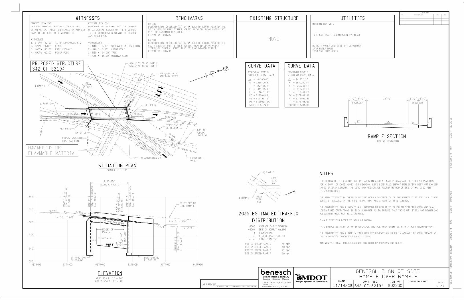
WITNESSES EXISTING STRUCTUREBENCHMARKS UTILITIES
NOTES
2035 ESTIMATED TRAFFIC
DISTRIBUTION
CURVE DATA
GENERAL PLAN OF SITE
S42 OF 82194
3459
(274)
6%
1 2
4129
(367)
13%
0000 AVERAGE DAILY TRAFFIC
(000) DESIGN HOURLY VOLUME
% COMMERCIAL
DIRECTIONAL TRAFFIC
TOTAL TRAFFIC
LOOKING UPSTATION
NONE
RAMP E OVER RAMP F
CONTROL PT# 758
DESCRIPTION: SET MAG NAIL IN CENTER
OF AN AERIAL TARGET ON FENCED-IN ASPHALT
PARKING LOT EAST OF LIVERNOIS ST.
WITNESSES:
1. S70^W 80.00’ CL OF LIVERNOIS ST.
2. S20^E 9.00’ FENCE
3. N60^W 85.00’ FIRE HYDRANT
4. N90^W 60.00’ POWER POLE
CONTROL PT# 784
DESCRIPTION: SET MAG NAIL IN CENTER
OF AN AERIAL TARGET ON THE SIDEWALK
IN THE NORTHWEST QUADRANT OF DRAGON
AND FISHER ST.
WITNESSES:
1. N40^E 8.00’ SIDEWALK INTERSECTION
2. S40^E 8.00’ LIGHT POLE
3. N10^W 54.00’ TREE
4. S45^W 15.00’ HIGHWAY SIGN
BM 310
DESCRIPTION: CHISELED ’X’ ON NW BOLT OF LIGHT POST ON THE
SOUTH SIDE OF FORT STREET ACROSS FROM BUILDING #6628 150’
WEST OF RADEMACHER STREET.
ELEVATION: 588.29
BM 311
DESCRIPTION: CHISELED ’X’ ON NW BOLT OF LIGHT POST ON THE
SOUTH SIDE OF FORT STREET ACROSS FROM BUILDING #6142
"FERGUSON FUNERAL HOME" 100’ EAST OF DRAGON STREET.
ELEVATION: 587.33
SCALE: 1" = 40’\ RAMP F
\ RAMP E
POSTED SPEED RAMP E 45 mph
DESIGN SPEED RAMP E 50 mph
POSTED SPEED RAMP F 45 mph
DESIGN SPEED RAMP F 50 mph
HAZARDOUS OR
FLAMMABLE MATERIAL
EXIST. MICHIGAN
CON. GAS LINE
REF PT A
\ RAMP E
\ RAMP F
NB I-75
REF PT B
EXIST UG
INT’L TRANSMISSION CO
DEPT OF
PUBLIC
LIGHTING
EXIST UTIL
WATER
SITUATION PLAN
570
560
550
580
590
600
6174+00
6176+00
6177+00
5174+00 5176+00
5177+00
6175+006174+006173+00 6176+00 6177+00 6178+00
RE
F P
T A
ST
A. 5174+
70.8
8
EL
. 585.1
9
RE
F P
T B
ST
A.
51
75
+8
7.3
5
EL
. 581.7
3
PR
OP
P.V
.I
ST
A 5
177+
35.0
0
EL
. 576.8
2
RAMP E SECTION
SHOULDER SHOULDER
1% 5%
DR
AW
N B
Y:
R
MG
DA
TE
:
10
/03
/08
CH
EC
KE
D B
Y:
KM
P
DA
TE
: 1
1/0
7/0
8
PROPOSED STRUCTURE
S42 OF 82194
5175
6175
RAMP F
PR
OP
P.V
.I.
ST
A 5
173+
92.3
6
EL
58
8.2
2
+0.53%-3.33%
116’-5 5/8 "
ALONG C RAMP EL
STA 5175+26.71 RAMP E
STA 6175+39.80 RAMP F
EXIST SAN TO
BE RELOCATED
RELOCATE EXIST
SANITARY SEWER
15
-3.33%+1.37%
PR
OP
P.V
.T.
ST
A 5
175+
54.4
6
EL
58
2.4
0
ELEVATIONVERT SCALE: 1" = 10’
HORIZ SCALE: 1" = 40’
THE DESIGN OF THIS STRUCTURE IS BASED ON CURRENT AASHTO STANDARD LRFD SPECIFICATIONS
FOR HIGHWAY BRIDGES HL-93 MOD LOADING. LIVE LOAD PLUS IMPACT DEFLECTION DOES NOT EXCEED
1/800 OF SPAN LENGTH. THE LOAD AND RESISTANCE FACTOR METHOD OF DESIGN WAS USED FOR
THIS STRUCTURE.
THE WORK COVERED BY THESE PLANS INCLUDES CONSTRUCTION OF THE PROPOSED BRIDGE. ALL OTHER
WORK IS INCLUDED IN THE ROAD PLANS THAT ARE A PART OF THIS CONTRACT.
THE CONTRACTOR SHALL LOCATE ALL UNDERGROUND UTILITIES PRIOR TO STARTING WORK AND SHALL
CONDUCT HIS OPERATIONS IN SUCH A MANNER AS TO ENSURE THAT THOSE UTILITIES NOT REQUIRING
RELOCATION WILL NOT BE DISTURBED.
PLAN ELEVATIONS REFER TO NAVD 88 DATUM.
THIS BRIDGE IS PART OF AN INTERCHANGE AND ALL AREA SHOWN IS WITHIN MDOT RIGHT-OF-WAY.
THE CONTRACTOR SHALL NOTIFY EACH UTILITY COMPANY 48 HOURS IN ADVANCE OF WORK IMPACTING
THAT COMPANY’S CONDUITS OR FACILITIES.
MINIMUM VERTICAL UNDERCLEARANCE COMPUTED BY PARSONS ENGINEERS.
FIL
E N
AM
E:
Ram
pE
ov
erF
po
s.d
gn
5%
MICHCON GAS MAIN
INTERNATIONAL TRANSMISSION OVERHEAD
DETROIT WATER AND SANITARY DEPARTMENT
16"! WATER MAIN
12"! SANITARY SEWER
L.V.C. = 300’
L.V.C. = 324’
PROPOSED RAMP E
CIRCULAR CURVE DATA
CURVE DATA
PROPOSED RAMP F
CIRCULAR CURVE DATA
= 18%%d38’09"
R = 1265.00 FT
T = 207.56 FT
L = 411.45 FT
E = 16.91 FT
PC = 5175+49.61
PI = 5177+57.17
PT = 5179+61.06
SUPER = 5.0% RT
= 14%%d37’07"
R = 1640.00 FT
T = 210.36 FT
L = 418.43 FT
E = 13.44 FT
PC = 6171+89.57
PI = 6173+99.93
PT = 6176+08.01
SUPER = 4.9% RT
EXIST GROUND
LINE RAMP E
(Typ.)
42" PPC BOX BEAM
BOT/FOOTING
EL 555.00
BOT/FOOTING
EL 556.00
4’-0" 4’-0" 16’-0" 6’-0" 4’-0"
10’-0" MIN.
8’-0"
MIN.
EDGE OF
PAVT.
14’-9"
MIN
CL
REX
SA
N7’-
0" x
5’-
0"
BO
X (D
WSD
)
EX SAN12" (DWSD)
EX SAN12" (DWSD)
EX SAN15" (DWSD)
EX S
AN
10"
(DW
SD)
EX SAN 15" X 20" (DWSD)
EX WATER 16" (DWSD)
120
kV &
CO
NT
RO
L C
AB
LE
IT
C
Michigan Department of Transportation
11/14/08
CONT. SEC.DATE JOB NO. DESIGN UNITSHEET
REVISIONS
DESCRIPTIONNO. BYDATE
222 N. Washington Square,
Suite 200
Lansing, Michigan 48933
APPROVEDCONSULTANT COORDINATING ENGINEER 802330 OF

RAMP E OVER RAMP F
GENERAL PLAN OF SITE - CROSS SECTION
S42 OF 82194 FIL
E N
AM
E:
RA
MP
Eo
verF
-xs.d
gn
DR
AW
N B
Y:
R
MG
DA
TE
:
10
/03
/08
CH
EC
KE
D B
Y:
MR
B D
AT
E:
10/0
3/0
8
22
37’-10 3/8 "
OUT TO OUT DECK FASCIA
3’-4
"
34’-7 3/8 "
1’-7 1/2 " 1’-7 1/2 "
2’-9" 5 SPA @ 6’-5 5/8 "(+) = 32’-4 3/8 " 2’-9"
(LOOKING UPSTATION)
CROSS SECTION
48"W x 42"H SPREAD PPC BOX BEAM
1.0%
5.0%
9"
DE
CK
5.0%
\ RAMP E & P.G.L.
VARIES 10’-0" MIN TO 10’-7 3/8 "
SHOULDER
16’-0"
LANE
VARIES 8’-0" MIN TO 8/-4 1/4 "
SHOULDER
5’-0
" +
1’-6" 1’-6"
LIMITS OF
EXCAVATION, FDN
LIMITS OF BACKFILL
STRUCTURE, CIPLIMITS OF LIGHTWEIGHT
AGGREGATE SLAG, LM
6’-0
"
LIMITS OF BACKFILL
STRUCTURE, CIP
ABUTMENT
SECTION THRU ABUTMENT B
LIMITS OF BACKFILL
STRUCTURE, CIP
(SHOWING LIMITS OF EXCAVATION AND BACKFILL)
(ABUTMENT B SHOWN, ABUTMENT A SIMILAR)
Michigan Department of Transportation
11/14/08
CONT. SEC.DATE JOB NO. DESIGN UNITSHEET
REVISIONS
DESCRIPTIONNO. BYDATE
222 N. Washington Square,
Suite 200
Lansing, Michigan 48933
APPROVEDCONSULTANT COORDINATING ENGINEER 802330 OF

GENERAL PLAN OF SITE
CH
EC
KE
D B
Y:
KM
P
D
AT
E:
10
/31
/08
DR
AW
N B
Y:
R
MG
D
AT
E:
10/0
9/0
8
1 2
1.5% 1.5%1.5%
1:10
1:4 1:4
1:10
EXISTING GROUND
1.5%1.5% 1.5%
RAMPS A AND C OVER NORFOLK SOUTHERN RR
2035 ESTIMATED TRAFFIC
DISTRIBUTION
0000 AVERAGE DAILY TRAFFIC
(000) DESIGN HOURLY VOLUME
% COMMERCIAL
DIRECTIONAL TRAFFIC
TOTAL TRAFFIC
PC
= 4
166+
40.7
9 C
ON
ST
PC
C =
2180+
42.2
5 C
ON
ST
PT
= 4
165+
01.3
1 C
ON
ST
4163
1164
3187
1165 3183 3184
1167 1166
3185
4166
2180 2181
4164
2182
2183
N 26%%d55’07"W 4165
1168
PI=
4162+46.7
7 C
ON
ST
4162
PROPOSED CURVE DATA
PROPOSED RAMP A
CIRCULAR CURVE DATA
PROPOSED RAMP C
CIRCULAR CURVE DATA
POSTED SPEED RAMP A 45 mph
DESIGN SPEED RAMP A 50 mph
POSTED SPEED I-75 55 mph
DESIGN SPEED I-75 60 mph
POSTED SPEED RAMP C 45 mph
DESIGN SPEED RAMP C 50 mph
POSTED SPEED I-75 55 mph
DESIGN SPEED I-75 60 mph
25’-0"
MIN
\ N.S.RR.
TRACK NO. 2
\ N.S.RR.
TRACK NO. 1
\ RAMP A
\ RAMP C
REF LINE A
REF LINE B
REF PT B2
STA 1165+91.46
(RAMP A)
REF PT A2
STA 1167+15.01
(RAMP A)
SITUATION PLAN
FIL
E N
AM
E:
RA
MP
AC
NS
RR
po
s.d
gn
REF PT A1
STA 3184+10.79
(RAMP C)
STA 11+35.97 (N.S.RR.TRACK NO.1)
= STA 1166+85.00 (RAMP A)
STA 11+11.95 (N.S.RR.TRACK NO.2)
= STA 3184+40.79 (RAMP C)
REF PT B1
STA 3185+34.36
(RAMP C)
CONTROL PT# 907
DESCRIPTION: SET MAG NAIL IN CENTER
OF ARIAL TARGET IN THE CONVERGENCE OF
THE EXIT RAMP OF I-75 AND FISHER, NORTH
OF CRAWFORD.
WITNESSES:
1. S75^W 15.00’ FENCE POST
2. N20^W 2.50’ EDGE CONCRETE
3. S20^E 12.00’ CENTERLINE FISHER
4. S05^W 51.00’ POWER POLE
WITNESSES
CONTROL PT# 758
DESCRIPTION: SET MAG NAIL IN CENTER
OF AN AERIAL TARGET ON FENCED-IN ASPHALT
PARKING LOT EAST OF LIVERNOIS ST.
WITNESSES:
1. S70^W 80.00’ \ OF LIVERNOIS ST.
2. S20^E 9.00’ FENCE
3. N60^W 85.00’ FIRE HYDRANT
4. N90^W 60.00’ POWER POLE
BENCHMARKS
BM 311
DESCRIPTION: CHISELED ’X’ ON NW BOLT OF LIGHT POST ON THE
SOUTH SIDE OF FORT STREET ACROSS FROM BUILDING #6142
"FERGUSON FUNERAL HOME" 100’ EAST OF DRAGON STREET.
ELEVATION: 587.33
BM 310
DESCRIPTION: CHISELED ’X’ ON NW BOLT OF LIGHT POST ON THE
SOUTH SIDE OF FORT STREET ACROSS FROM BUILDING #6628 150’
WEST OF RADEMACHER STREET.
ELEVATION: 588.29 UTILITIES
MICHCON 12" DIA GAS MAIN
DETROIT PUBLIC LIGHTING
DPL LIGHTING CONDUITS
DETROIT WATER AND SANITARY
DISTRICT 15" x 20" SANITARY SEWER
R01-4 OF 82194
NOTES
THE DESIGN OF THIS STRUCTURE IS BASED ON CURRENT AASHTO STANDARD
LRFD SPECIFICATIONS FOR HIGHWAY BRIDGES HL-93 MOD LOADING. LIVE LOAD
PLUS IMPACT DEFLECTION DOES NOT EXCEED 1/800 OF SPAN LENGTH. THE LOAD
AND RESISTANCE FACTOR METHOD OF DESIGN WAS USED FOR THIS STRUCTURE.
THE WORK COVERED BY THESE PLANS INCLUDES CONSTRUCTION OF THE PROPOSED
BRIDGE. ALL OTHER WORK IS INCLUDED IN THE ROAD PLANS THAT ARE A PART OF
THIS CONTRACT.
THE CONTRACTOR SHALL LOCATE ALL UNDERGROUND UTILITIES PRIOR TO STARTING
WORK AND SHALL CONDUCT HIS OPERATIONS IN SUCH A MANNER AS TO ENSURE THAT
THOSE UTILITIES NOT REQUIRING RELOCATION WILL NOT BE DISTURBED.
PLAN ELEVATIONS REFER TO NAVD 88 DATUM.
THE GROUND ADJACENT TO THE TRACKS AND THE STRUCTURE SHALL BE GRADED BY
THE CONTRACTOR TO PROVIDE DRAINAGE.
MEASURES SHALL BE TAKEN TO PREVENT DEBRIS FROM FALLING FROM THE STRUCTURE.
THIS BRIDGE IS PART OF AN INTERCHANGE AND ALL AREA SHOWN IS WITHIN MDOT
RIGHT-OF-WAY.
THE CONTRACTOR SHALL NOTIFY EACH UTILITY COMPANY 48 HOURS IN ADVANCE OF
WORK IMPACTING THAT COMPANY’S CONDUITS OR FACILITIES.
MINIMUM VERTICAL UNDERCLEARANCE COMPUTED BY PARSONS ENGINEERS.
4,200
(690)
43%
10,300
(770)
54%
\ RAMP A \ RAMP C
570
580
590
600
610
620
630
640
REF PT A2
STA 1167+15.01
EL. 623.66
1165116611671168
+4.82%
REF PT B2
STA 1165+91.46
EL. 617.73
L
38" WEB P GIRDEREXP
FIX
2
1
2
1
23
’-0
"
MIN
CL
R
\ TRACK
NO. 2
25’-0"
MIN
*
\ TRACK
NO. 1
**14’-0"
MIN
\ PLAZA SERVICE
DRIVE
BOT/FTG
EL 585.00BOT/FTG
EL 585.00
WINGWALL
WINGWALL
VERT SCALE: 1" = 10’
HORIZ SCALE: 1" = 40’
ELEVATION - RAMP A*
**
DIMENSIONS AT RIGHT ANGLE TO TRACKS
DIMENSIONS AT RIGHT ANGLE TO SERVICE DRIVE
3186318531843183
570
580
590
600
610
620
630
640
VERT SCALE: 1" = 10’
HORIZ SCALE: 1" = 40’
ELEVATION - RAMP C
REF PT A1
STA 3184+10.79
EL. 624.17
REF PT B1
STA 3185+34.36
EL. 618.09-4.92%WINGWALL
EXP
38" WEB P GIRDER
23
’-0
"
MIN
CL
R
FIX
WINGWALL**
14’-0"
MIN 1
2
\ PLAZA SERVICE
DRIVE
1
2
\ TRACK
NO. 1
25’-0"
MIN
*
\ TRACK
NO. 2
BOT/FTG
EL 585.00BOT/FTG
EL 585.00
3180
PVI STA 3180+45.60
EL. 642.34
LVC = 445’
+4.40%
1170
PVI STA 1170+41.30
EL. 639.41
-3.57%
LVC = 400’
= 62%%d02’22"
R = 868.00 FT
T = 521.95 FT
L = 939.86 FT
E = 144.85 FT
PC = 1157+81.46
PI = 1163+03.41
PT = 1167+21.32
= 62%%d02’22"
R = 844.00 FT
T = 507.52 FT
L = 913.88 FT
E = 140.84 FT
PC = 3184+04.49
PI = 3189+12.01
PT = 3193+18.37
PROPOSED STRUCTURE
R01-4 OF 82194
PROPOSED STRUCTURE
R01-3 OF 82194
RETAINING
WALL
WINGWALL
WINGWALL
WINGWALL
WINGWALL
123’-6 5/8 " 123’-6 7/8 "
2
1
1
SCALE: 1" = 40’
EX SAN 15" X 20" (DWSD) EX
SA
N 1
5" X
20
" (
DW
SD
)
EX
SA
N 1
0" (
DW
SD
)
EX SAN
10" (DWSD)
EX
SA
N 1
2" (
DW
SD
)
MCI CONDUIT
MICHCON 12"
DP
L
DPL
DPL
Michigan Department of Transportation
11/14/08
CONT. SEC.DATE JOB NO. DESIGN UNITSHEET
REVISIONS
DESCRIPTIONNO. BYDATE
222 N. Washington Square,
Suite 200
Lansing, Michigan 48933
APPROVEDCONSULTANT COORDINATING ENGINEER 802330 OF
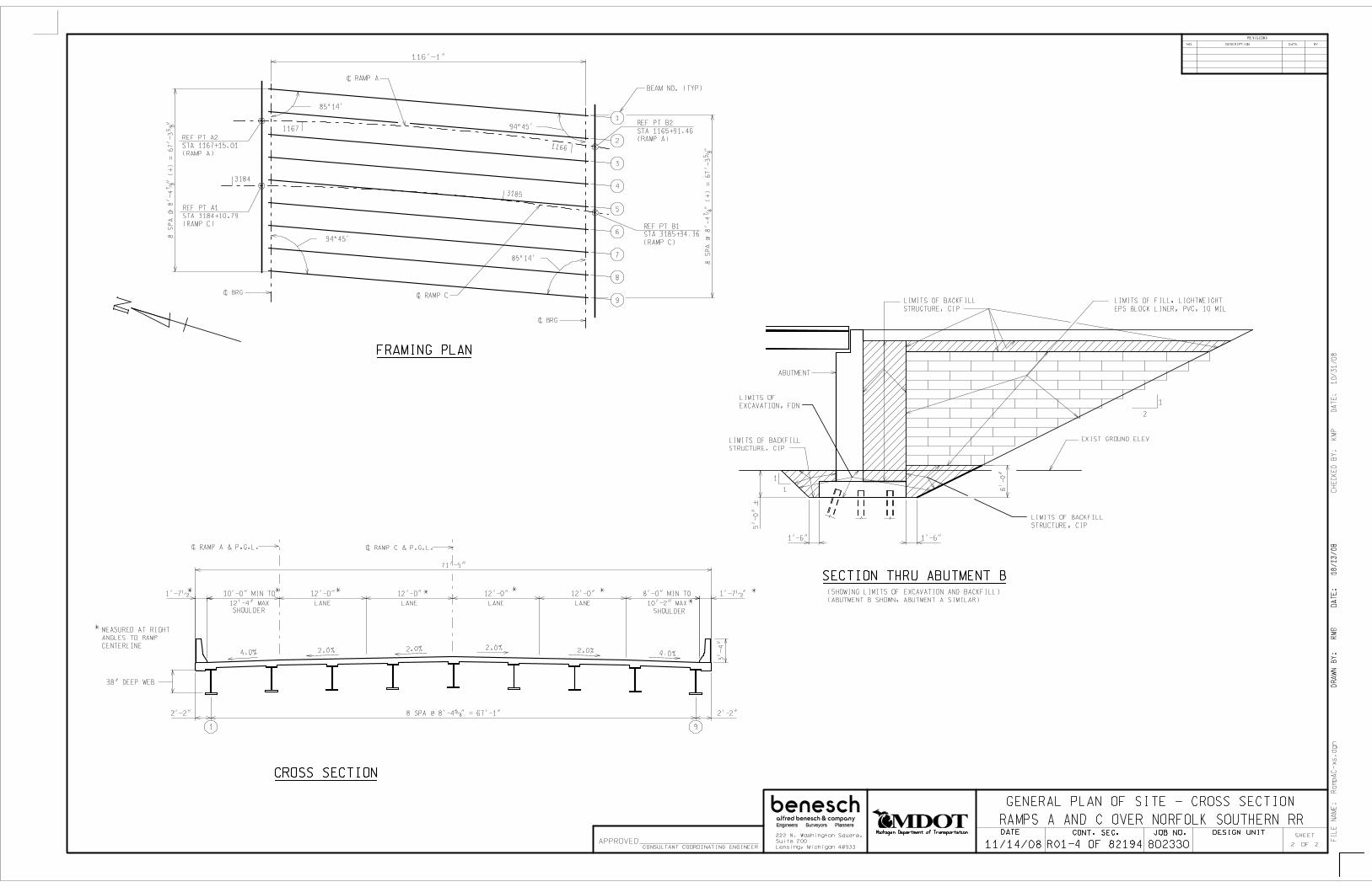
SHOULDER
* **
*
*1’-7 1/2 "1’-7 1/2 "
38" DEEP WEB
CROSS SECTION
4.0%2.0% 2.0%2.0%2.0%4.0%
**
SHOULDER
*
*
1
BEAM NO. (TYP)
2
3
4
5
6
7
9
8
1167
1166
3185
3184
REF PT A2
STA 1167+15.01
(RAMP A)
REF PT A1
STA 3184+10.79
(RAMP C) REF PT B1
STA 3185+34.36
(RAMP C)
REF PT B2
STA 1165+91.46
(RAMP A)
116’-1"
8 S
PA
@ 8
’-4 7
/8 "
(+
) =
67’-
3 5
/8 "
8 S
PA
@ 8
’-4 7
/8 "
(+
) =
67’-
3 5
/8 "
\ BRG
\ BRG\ RAMP C
\ RAMP A
FRAMING PLAN
94%%d45’
85%%d14’
94%%d45’
85%%d14’
91
\ RAMP A & P.G.L. \ RAMP C & P.G.L.
2 2
CH
EC
KE
D B
Y:
KM
P D
AT
E:
10/3
1/0
8D
RA
WN
BY
: K
MP
D
AT
E:
10/1
3/0
8
DR
AW
N B
Y:
R
MG
D
AT
E:
08/2
2/0
8
FIL
E N
AM
E:
Ram
pA
C-x
s.d
gn
GENERAL PLAN OF SITE - CROSS SECTION
RAMPS A AND C OVER NORFOLK SOUTHERN RR
R01-4 OF 82194
2
1
1
1 6’-0"
LIMITS OF BACKFILL
STRUCTURE, CIP
LIMITS OF
EXCAVATION, FDN
LIMITS OF BACKFILL
STRUCTURE, CIP
LIMITS OF BACKFILL
STRUCTURE, CIP5’-0" +
71’-5"
8’-0" MIN TO
10’-2" MAX
12’-0"
LANE
12’-0"
LANE
12’-0"
LANE
12’-0"
LANE
10’-0" MIN TO
12’-4" MAX
2’-2"
8 SPA @ 8’-4 5/8 " = 67’-1"
2’-2"
3’-4"
MEASURED AT RIGHT
ANGLES TO RAMP
CENTERLINE
ABUTMENT
1’-6" 1’-6"
EXIST GROUND ELEV
SECTION THRU ABUTMENT B
(SHOWING LIMITS OF EXCAVATION AND BACKFILL)
(ABUTMENT B SHOWN, ABUTMENT A SIMILAR)
LIMITS OF FILL, LIGHTWEIGHT
EPS BLOCK LINER, PVC, 10 MIL
Michigan Department of Transportation
11/14/08
CONT. SEC.DATE JOB NO. DESIGN UNITSHEET
REVISIONS
DESCRIPTIONNO. BYDATE
222 N. Washington Square,
Suite 200
Lansing, Michigan 48933
APPROVEDCONSULTANT COORDINATING ENGINEER 802330 OF
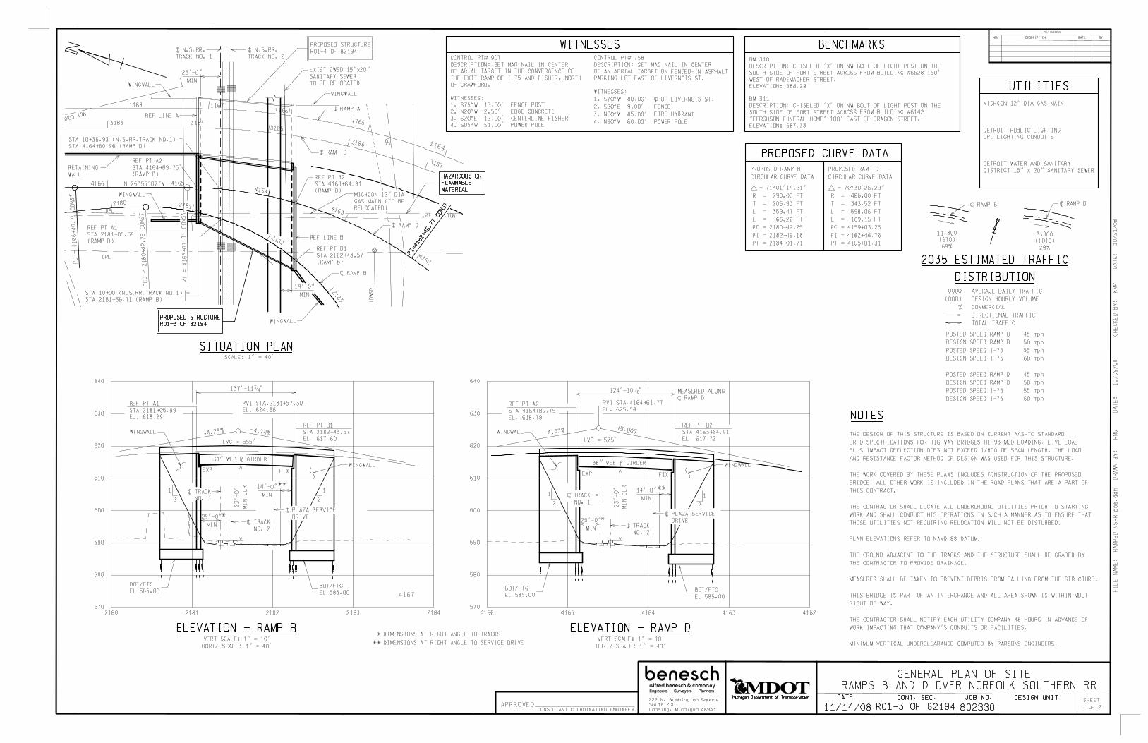
BENCHMARKS
UTILITIES
NOTES
GENERAL PLAN OF SITE
CH
EC
KE
D B
Y:
KM
P
D
AT
E:
10
/31
/08
DR
AW
N B
Y:
R
MG
D
AT
E:
10/0
9/0
8
1 2
1.5% 1.5%1.5%
1:10
1:4 1:4
1:10
EXISTING GROUND
1.5%1.5% 1.5%
CONTROL PT# 907
DESCRIPTION: SET MAG NAIL IN CENTER
OF ARIAL TARGET IN THE CONVERGENCE OF
THE EXIT RAMP OF I-75 AND FISHER, NORTH
OF CRAWFORD.
WITNESSES:
1. S75^W 15.00’ FENCE POST
2. N20^W 2.50’ EDGE CONCRETE
3. S20^E 12.00’ CENTERLINE FISHER
4. S05^W 51.00’ POWER POLE
WITNESSES
BM 311
DESCRIPTION: CHISELED ’X’ ON NW BOLT OF LIGHT POST ON THE
SOUTH SIDE OF FORT STREET ACROSS FROM BUILDING #6142
"FERGUSON FUNERAL HOME" 100’ EAST OF DRAGON STREET.
ELEVATION: 587.33
BM 310
DESCRIPTION: CHISELED ’X’ ON NW BOLT OF LIGHT POST ON THE
SOUTH SIDE OF FORT STREET ACROSS FROM BUILDING #6628 150’
WEST OF RADEMACHER STREET.
ELEVATION: 588.29
RAMPS B AND D OVER NORFOLK SOUTHERN RR
2035 ESTIMATED TRAFFIC
DISTRIBUTION
0000 AVERAGE DAILY TRAFFIC
(000) DESIGN HOURLY VOLUME
% COMMERCIAL
DIRECTIONAL TRAFFIC
TOTAL TRAFFIC
11,800
(970)
69%
\ RAMP B
S 26%%d 55’ 07" E
N 26%%d 55’ 07" W
PROPOSED CURVE DATA
PROPOSED RAMP B
CIRCULAR CURVE DATA
PROPOSED RAMP D
CIRCULAR CURVE DATA
= 70%%d30’26.29"
R = 486.00 FT
T = 343.52 FT
L = 598.06 FT
E = 109.15 FT
PC = 4159+03.25
PI = 4162+46.76
PT = 4165+01.31
= 71%%d01’14.21"
R = 290.00 FT
T = 206.93 FT
L = 359.47 FT
E = 66.26 FT
PC = 2180+42.25
PI = 2182+49.18
PT = 2184+01.71
\ RAMP D
8,800
(1010)
29%
CONTROL PT# 758
DESCRIPTION: SET MAG NAIL IN CENTER
OF AN AERIAL TARGET ON FENCED-IN ASPHALT
PARKING LOT EAST OF LIVERNOIS ST.
WITNESSES:
1. S70^W 80.00’ \ OF LIVERNOIS ST.
2. S20^E 9.00’ FENCE
3. N60^W 85.00’ FIRE HYDRANT
4. N90^W 60.00’ POWER POLE
FIL
E N
AM
E:
RA
MP
BD
NS
RR
po
s.d
gn
POSTED SPEED RAMP B 45 mph
DESIGN SPEED RAMP B 50 mph
POSTED SPEED I-75 55 mph
DESIGN SPEED I-75 60 mph
POSTED SPEED RAMP D 45 mph
DESIGN SPEED RAMP D 50 mph
POSTED SPEED I-75 55 mph
DESIGN SPEED I-75 60 mph
+4.29% -4.74%
2180 2181 2182 2183 2184
570
580
590
600
610
620
PVI STA.2181+57.30
EL. 624.66
38" WEB P GIRDERL
EXP FIX
2
1
2
1
23
’-0
"
MIN
CL
R 14’-0"
MIN
**
25’-0"
MIN\ TRACK
NO. 2
\ TRACK
NO. 1
\ PLAZA SERVICE
DRIVE
BOT/FTG
EL 585.00
BOT/FTG
EL 585.00
VERT SCALE: 1" = 10’
HORIZ SCALE: 1" = 40’
630
640
*
* DIMENSIONS AT RIGHT ANGLE TO TRACKS
** DIMENSIONS AT RIGHT ANGLE TO SERVICE DRIVE
MICHCON 12" DIA GAS MAIN
DETROIT PUBLIC LIGHTING
DPL LIGHTING CONDUITS
DETROIT WATER AND SANITARY
DISTRICT 15" x 20" SANITARY SEWER
PC
= 4
166+
40.7
9 C
ON
ST
PC
C =
2180+
42.2
5 C
ON
ST
PT
= 4
165+
01.3
1 C
ON
ST
4163
1164
3187
1165
3186
3183 3184
1167 1166
3185
4166
2180 2181
4164
2182
2183
N 26%%d55’07"W 4165
1168
PI=
4162+46.7
7 C
ON
ST
4162
25’-0"
MIN
\ N.S.RR.
TRACK NO. 2
\ N.S.RR.
TRACK NO. 1
\ RAMP A
\ RAMP C
REF LINE A
REF LINE B
REF PT B2
STA 4163+64.91
(RAMP D)MICHCON 12" DIA
GAS MAIN (TO BE
RELOCATED)
HAZARDOUS OR
FLAMMABLE
MATERIAL
\ RAMP D
\ RAMP B
REF PT B1
STA 2182+43.57
(RAMP B)
REF PT A2
STA 4164+89.75
(RAMP D)
REF PT A1
STA 2181+05.59
(RAMP B)
STA 10+36.93 (N.S.RR.TRACK NO.1) =
STA 4164+60.96 (RAMP D)
STA 10+00 (N.S.RR.TRACK NO.1) =
STA 2181+36.71 (RAMP B)
SITUATION PLAN
EXIST DWSD 15"x20"
SANITARY SEWER
TO BE RELOCATED
14’-0"
MIN
THE DESIGN OF THIS STRUCTURE IS BASED ON CURRENT AASHTO STANDARD
LRFD SPECIFICATIONS FOR HIGHWAY BRIDGES HL-93 MOD LOADING. LIVE LOAD
PLUS IMPACT DEFLECTION DOES NOT EXCEED 1/800 OF SPAN LENGTH. THE LOAD
AND RESISTANCE FACTOR METHOD OF DESIGN WAS USED FOR THIS STRUCTURE.
THE WORK COVERED BY THESE PLANS INCLUDES CONSTRUCTION OF THE PROPOSED
BRIDGE. ALL OTHER WORK IS INCLUDED IN THE ROAD PLANS THAT ARE A PART OF
THIS CONTRACT.
THE CONTRACTOR SHALL LOCATE ALL UNDERGROUND UTILITIES PRIOR TO STARTING
WORK AND SHALL CONDUCT HIS OPERATIONS IN SUCH A MANNER AS TO ENSURE THAT
THOSE UTILITIES NOT REQUIRING RELOCATION WILL NOT BE DISTURBED.
PLAN ELEVATIONS REFER TO NAVD 88 DATUM.
THE GROUND ADJACENT TO THE TRACKS AND THE STRUCTURE SHALL BE GRADED BY
THE CONTRACTOR TO PROVIDE DRAINAGE.
MEASURES SHALL BE TAKEN TO PREVENT DEBRIS FROM FALLING FROM THE STRUCTURE.
THIS BRIDGE IS PART OF AN INTERCHANGE AND ALL AREA SHOWN IS WITHIN MDOT
RIGHT-OF-WAY.
THE CONTRACTOR SHALL NOTIFY EACH UTILITY COMPANY 48 HOURS IN ADVANCE OF
WORK IMPACTING THAT COMPANY’S CONDUITS OR FACILITIES.
MINIMUM VERTICAL UNDERCLEARANCE COMPUTED BY PARSONS ENGINEERS.
WINGWALL
WINGWALL
ELEVATION - RAMP B
-4.43%+5.00%
4166 4165 4164 4163 4162
570
580
590
600
610
620
PVI STA.4164+61.77
EL. 625.54
38" WEB P GIRDERL
EXP FIX
2
1
2
1
23
’-0
"
MIN
CL
R 14’-0"
MIN
**
\ TRACK
NO. 2
\ TRACK
NO. 1
\ PLAZA SERVICE
DRIVE
BOT/FTG
EL 585.00
BOT/FTG
EL 585.00
VERT SCALE: 1" = 10’
HORIZ SCALE: 1" = 40’
630
640
*
WINGWALL
WINGWALL
ELEVATION - RAMP D
4167
25’-0"
MIN
REF PT A1
STA 2181+05.59
EL. 618.29
REF PT B1
STA 2182+43.57
EL. 617.60
REF PT A2
STA 4164+89.75
EL. 618.78
REF PT B2
STA 4163+64.91
EL. 617.72
R01-3 OF 82194
PROPOSED STRUCTURE
R01-3 OF 82194
PROPOSED STRUCTURE
R01-4 OF 82194
WINGWALL
WINGWALL
WINGWALL
WINGWALL
SCALE: 1" = 40’
137’-11 3/4 "
LVC = 555’ LVC = 575’
124’-10 1/8 " MEASURED ALONG
\ RAMP D
RETAINING
WALL
A A
EX SAN 15" X 20" (DWSD) EX
SA
N 1
5" X
20
" (
DW
SD
)
EX
SA
N 1
0" (
DW
SD
)
EX SAN
10" (DWSD)
EX
SA
N 1
2" (
DW
SD
)
MCI CONDUIT
MICHCON 12"
DP
L
DPL
DPL
Michigan Department of Transportation
11/14/08
CONT. SEC.DATE JOB NO. DESIGN UNITSHEET
REVISIONS
DESCRIPTIONNO. BYDATE
222 N. Washington Square,
Suite 200
Lansing, Michigan 48933
APPROVEDCONSULTANT COORDINATING ENGINEER 802330 OF

2 2
CH
EC
KE
D B
Y:
KM
P D
AT
E:
10/3
1/0
8D
RA
WN
BY
: K
MP
D
AT
E:
10/1
3/0
8
CH
EC
KE
D B
Y:
KM
P
D
AT
E:
08
/22
/08
DR
AW
N B
Y:
R
MG
D
AT
E:
08/2
2/0
8
FIL
E N
AM
E:
Ram
pB
D-x
s.d
gn
GENERAL PLAN OF SITE - CROSS SECTION
RAMPS B AND D OVER NORFOLK SOUTHERN RR
VARIES 10’-0" TO 17’-11"
SHOULDER
12’-0"
LANE
12’-0"
LANE
VARIES
12’-0"
LANE
12’-0"
LANE
VARIES 10’-0" MIN
TO 13’-5 1/4 "
SHOULDER
81’-2 1/4 "
125’-9 5/8 "
MEASURED ALONG REF LINE A
MEASURED ALONG REF LINE B
* * * * * * * *1’-7 1/2 "
*
38" DEEP WEB
CROSS SECTION
R01-3 OF 82194
4.0%
2.0% 2.0%2.0%2.0%
4.0%2.0%
116’-1"
\ BRG
\ BRG
2182
4164
2181
4165
FRAMING PLAN
REF PT A2
STA 4164+89.75
(RAMP D)
REF PT A1
STA 2181+05.59
(RAMP B)
REF PT B2
STA 4163+64.91
(RAMP D)
REF PT B1
STA 2182+43.57
(RAMP B)
3’-4"
1’-7 1/2 "
\ RAMP B
\ RAMP D
13
12
14
11
10
9
8
7
6
5
4
3
2
1
116%%d47’
81%%d55’
98%%d06’
63%%d13’
13
SP
A @
5’-
11
7/8
" (
-) =
77
’-1
0 7
/8 "
13
SP
A @
9’-2
3/4
" (
-) =
11
9’-1
1"
MEASURED PERP
TO GIRDER 1
MEASURED PERP
TO GIRDER 14
2’-2"
13 SPA @ 5’-11 7/8 " (-) = 77’-10 1/8 "
13 SPA @ 9’-2 3/4 " (-) = 119’-11"
2’-2"
14
\ RAMP D & P.G.L.
*
1
\ RAMP B & P.G.L.
GIRDER NO. (TYP)
MEASURED AT RIGHT
ANGLES TO RAMP
CENTERLINE
2
1
1
1 6’-0"
LIMITS OF BACKFILL
STRUCTURE, CIP
LIMITS OF
EXCAVATION, FDN
LIMITS OF BACKFILL
STRUCTURE, CIP
LIMITS OF BACKFILL
STRUCTURE, CIP5’-0" +
ABUTMENT
1’-6" 1’-6"
EXIST GROUND ELEV
SECTION THRU ABUTMENT B
(SHOWING LIMITS OF EXCAVATION AND BACKFILL)
(ABUTMENT B SHOWN, ABUTMENT A SIMILAR)
LIMITS OF FILL, LIGHTWEIGHT
EPS BLOCK LINER, PVC, 10 MIL
Michigan Department of Transportation
11/14/08
CONT. SEC.DATE JOB NO. DESIGN UNITSHEET
REVISIONS
DESCRIPTIONNO. BYDATE
222 N. Washington Square,
Suite 200
Lansing, Michigan 48933
APPROVEDCONSULTANT COORDINATING ENGINEER 802330 OF

SITUATION PLANSCALE: 1" = 40’
\ I-75
90^
NOTES
GENERAL PLAN OF SITE
90^90
^
605
600
595
590
585
580
ELEVATIONVERT SCALE: 1" = 10’
HORIZ SCALE: 1" = 40’
17
’-0
"
MIN
VE
RT
CL
R
\ SOUTHBOUND
SERVICE DRIVE
\ I-75
(NB)
\ I-75
(SB)
610
EXPEXP
FIX
EX SAN 15" (DWSD)
EX SAN 15" (DWSD)
SOLVAY AVE PEDESTRIAN BRIDGE OVER I-75
189’-0"
88’-0"
101’-0"
STA 5+74.16 (BRIDGE)
STA 0+00.00 (BRIDGE)
BOT/FTG
EL 587.00
BOT/FTG
EL 590.50
BOT/FTG
EL 580.00
BOT/FTG
EL 580.00
BOT/FTG
EL 580.00
EXISTING STRUCTURE
PO1 of 82194
PROPOSED STRUCTURE
PO1 of 82194
REF PT 2
STA 3+09.88 (BRIDGE)
STA 133+79.55 (I-75)
\ I-75 &
REF LINE 2
REF LINE 1 REF LINE 3
WITNESSES
UTILITIES
EXISTING STRUCTURE
TO BE CONFIRMED
BENCHMARKS
BM 308
DESCRIPTION: CHISELED ’X’ ON NORTH BOLT OF METAL POWER POLE IN THE SW QUADRANT
OF FORT STREET AND SPRINGWELLS AVENUE.
ELEVATION: 588.18
BM 309
DESCRIPTION: CHISELED ’X’ ON SW BOLT OF AN ABANDONED SIGN POST ON A CONCRETE
BASE IN THE NW QUADRANT OF FORT STREET AND GREEN STREET NORTH IN THE PARKING
LOT OF "KING MOTZ BURGERS".
ELEVATION: 591.85
CONTROL PT# 788
DESCRIPTION: SET MAG NAIL IN CENTER
OF AN AERIAL TARGET ON THE NORTH
SHOULDER OF THE OFF-RAMP FROM I-75 S
AT EXIT 45.
WITNESSES:
1. N60^W 15.00’ CONCRETE BASE OF LIGHT POLE
2. N60^E 15.00’ END OF CONCRETE BARRIER
3. N20^W 24.00’ FENCE
4. S20^E 2.00’ BACK OF CURB
CONTROL PT# 765
DESCRIPTION: SET MAG NAIL IN CENTER
F AN AERIAL TARGET AT THE CL OF SOLVAY ST.
AND SOUTH OF FISHER W ST.
WITNESSES:
1. N20^W 100.00’ CL OF FISHER W ST.
2. N45^E 24.00’ POWER POLE
3. N70^E 54.00’ NORTHWEST CORNER OF BUILDING
4. S15^W 45.00’ FENCE POST
REF PT 1
STA 2+09.04 (BRIDGE)
STA 4+18.15 (BRIDGE)
REF PT 3
THE DESIGN OF THIS STRUCTURE IS BASED ON CURRENT AASHTO STANDARD SPECIFICATIONS
FOR HIGHWAY BRIDGES H-10 LOADING. LIVE LOAD PLUS IMPACT DEFLECTION DOES NOT EXCEED
1/500 OF SPAN LENGTH.
THE WORK COVERED BY THESE PLANS INCLUDES REMOVAL OF THE EXISTING PEDESTRIAN BRIDGE, CONSTRUCTION
OF THE PROPOSED BRIDGE AND RAMPS, AND PLACING SLOPE PAVING TO THE LIMITS SHOWN. ALL OTHER WORK IS
INCLUDED IN THE ROAD PLANS THAT ARE A PART OF THIS CONTRACT.
THE CONTRACTOR SHALL LOCATE ALL UNDERGROUND UTILITIES PRIOR TO STARTING WORK AND SHALL
CONDUCT HIS OPERATIONS IN SUCH A MANNER AS TO ENSURE THAT THOSE UTILITIES NOT REQUIRING
RELOCATION WILL NOT BE DISTURBED.
PLAN ELEVATIONS REFER TO NAVD 88 DATUM.
MEASURES SHALL BE TAKEN TO PREVENT DEBRIS FROM FALLING FROM THE STRUCTURE.
THIS BRIDGE IS WITHIN MDOT RIGHT-OF-WAY.
THE CONTRACTOR SHALL NOTIFY EACH UTILITY COMPANY 48 HOURS IN ADVANCE OF WORK IMPACTING
THAT COMPANY’S CONDUITS OR FACILITIES.
THE VERTICAL MINIMUM CLEARANCE COMPUTATIONS WERE PREPARED BY PARSONS ENGINEERS.
\ NORTHBOUND
SERVICE DRIVE
BUILT IN 1966, THE EXISTING STRUCTURE IS A TWO-SPAN PEDESTRIAN BRIDGE (90’-0", 90’-0") WITH A MULTI-SPAN RAMP AT
EITHER END. THE MAIN BRIDGE CONSISTS OF THREE LINES OF WF33x130 ROLLED BEAMS ON CONCRETE PIERS AND SPREAD
FOOTINGS. THE DECK THICKNESS IS 6" AND THE TOTAL WIDTH IS 9’-6" (8’-0" CLEAR). THE MINIMUM VERTICAL CLEARANCE IS
14’-6". RAMP A CONSISTS OF FIVE CONCRETE SLAB SPANS (41’-9", 19’-0", 19’-0", 19’-0", 19’-0"). RAMP B CONSISTS
OF FOUR CONCRETE SLAB SPANS (68’-9" - 19’-0" - 19’-0" - 19’-0"). BOTH RAMPS HAVE A DECK THICKNESS OF 9" AND
THE FIRST SPANS ARE ON FILL. THE EXISTING STRUCTURE IS ABOUT 110’ SOUTH OF THE PROPOSED STRUCTURE.
CH
EC
KE
D B
Y:
MR
B
D
AT
E:
09
/22
/08
FIL
E N
AM
E:
so
lvay
-po
s.d
gn
DR
AW
N B
Y:
V
H
D
AT
E:
0
9/1
8/0
8
BENCH (TYP)
P01 OF 82194 1 2
RETAINING WALL
SOUNDWALL
7’-9" 34’-6" 31’-0" 31’-0" 31’-0" 28’-6"
EDGE OF
PAVEMENT
EDGE OF
PAVEMENT
12’-3"37’-6"33’-0"34’-0"36’-6"36’-6"31’-6"
13’-0"
MIN CLR
14’-9"
MIN CLR
11’-9"
MIN CLR
11’-9"
MIN CLR
28" WEB
> GIRDER
130
13
1 1
32
133
134
135
31
35
31
36
0
1 2 3 4
5
10
11
12
13
14
PC = 14+15.66 CONST
15
PI = 15+30.69 CONST
SO
LV
AY
ST
Michigan Department of Transportation
11/14/08
CONT. SEC.DATE JOB NO. DESIGN UNITSHEET
REVISIONS
DESCRIPTIONNO. BYDATE
222 N. Washington Square,
Suite 200
Lansing, Michigan 48933
APPROVEDCONSULTANT COORDINATING ENGINEER 802330 OF

CONCRETE
DECK
PROTECTIVE FENCE
PIER CAP
PIER COLUMN (TYP)
3’-0
"
14-0
15’-0"
GENERAL PLAN OF SITE
9"
SOLVAY AVE PEDESTRIAN BRIDGE OVER I-75
FOOTING
PROFILEVERT SCALE: 1" = 10’HORIZ SCALE: 1" = 40’
TYPICAL PEDESTRIAN
BRIDGE SECTION AT SOLVAY AVE
CH
EC
KE
D B
Y:
MR
B D
AT
E:
09/2
2/0
8F
ILE
NA
ME
: s
olv
ay2-p
os.d
gn
DR
AW
N B
Y:
V
H D
AT
E:
09/1
8/0
8
P01 OF 82194 2 2
605
600
595
590
585
580
610
28" WEB > GIRDER
(TYP)
0+
29
.00
EL
593.7
7
591.3
5
0+
34
.00
EL
593.7
7
0+
63
.00
EL
596.1
9
+8.3
4%
0+
73
.00
EL
596.1
9
1+
02
.00
EL
598.6
1
+8.3
4%
1+
07
.00
EL
598.6
1
+8.3
4%
1+
36
.00
EL
601.0
3
+8.3
4%
1+
41
.00
EL
601.0
3
1+
69
.00
EL
603.3
6
+8.3
2%
1+
74
.00
EL
603.3
6
2+
02
.00
EL
605.6
9
+8.3
2%
2+
16.0
4
EL
605.6
9
+2.00%
3+
13.6
3
EL
607.6
4
-2.00%
L = 150’
4+
11.2
2
EL
605.6
94
+2
5.1
1
EL
605.6
9
-8.32%
4+
50
.11
EL
603.6
14
+5
5.1
1
EL
603.6
1
-8.35%
4+
81
.11
EL
601.4
44
+8
6.1
1
EL
601.4
4
-8.35%
5+
12
.11
EL
599.2
7
-8.35%
5+
17
.11
EL
599.2
7
-8.35%
5+
43
.11
EL
59
7.1
0
5+
48
.11
EL
597.1
0
594.9
3
Michigan Department of Transportation
11/14/08
CONT. SEC.DATE JOB NO. DESIGN UNITSHEET
REVISIONS
DESCRIPTIONNO. BYDATE
222 N. Washington Square,
Suite 200
Lansing, Michigan 48933
APPROVEDCONSULTANT COORDINATING ENGINEER 802330 OF

SITUATION PLANSCALE: 1" = 40’
17
’-0
"
MIN
VE
RT
CL
R
\ I-75
(NB)
\ I-75
(SB)
EXP
FIX
EXP
ELEVATIONVERT SCALE: 1" = 10’
HORIZ SCALE: 1" = 40’
585
590
595
600
605
610
\ I-75 25
26
27
28
31
44
31
45
31
46
NORTHBOUND
SERVICE DRIVE
88%
%d5
3’13
"89%%
d45’10"
88%%
d18’0"
EX
WA
TE
R 1
2" (D
WS
D)
CO
MC
AS
T C
OA
XIA
L (A
G)
DP
L
EX WATER 54"
(DWSD)
WITNESSES
BENCHMARKS
UTILITIES
EXISTING STRUCTURE
THE DESIGN OF THIS STRUCTURE IS BASED ON CURRENT AASHTO STANDARD SPECIFICATIONS
FOR HIGHWAY BRIDGES H-10 LOADING. LIVE LOAD PLUS IMPACT DEFLECTION DOES NOT EXCEED
1/500 OF SPAN LENGTH.
THE WORK COVERED BY THESE PLANS INCLUDES REMOVAL OF THE EXISTING BRIDGE, CONSTRUCTION
OF THE PROPOSED BRIDGE, AND PLACING SLOPE PAVING TO THE LIMITS SHOWN. ALL OTHER WORK IS
INCLUDED IN THE ROAD PLANS THAT ARE A PART OF THIS CONTRACT.
THE CONTRACTOR SHALL LOCATE ALL UNDERGROUND UTILITIES PRIOR TO STARTING WORK AND SHALL
CONDUCT HIS OPERATIONS IN SUCH A MANNER AS TO ENSURE THAT THOSE UTILITIES NOT REQUIRING
RELOCATION WILL NOT BE DISTURBED.
PLAN ELEVATIONS REFER TO NAVD 88 DATUM.
MEASURES SHALL BE TAKEN TO PREVENT DEBRIS FROM FALLING FROM THE STRUCTURE.
THIS BRIDGE IS WITHIN MDOT RIGHT-OF-WAY.
THE CONTRACTOR SHALL NOTIFY EACH UTILITY COMPANY 48 HOURS IN ADVANCE OF WORK IMPACTING
THAT COMPANY’S CONDUITS OR FACILITIES.
THE VERTICAL MINIMUM CLEARANCE COMPUTATIONS WERE PREPARED BY PARSONS ENGINEERS.
NOTES
EX SAN 24" (DWSD)
COMCAST COAXIAL (AG)DPL
MICHCON 3" PLASTIC EX WATER 54" (DWSD)
GENERAL PLAN OF SITE
BEARD AVE PEDESTRIAN BRIDGE OVER I-75
EX SAN 24"
(DWSD)
MICHCON
3" PLASTIC
190’-0"
89’-0"
101’-0"
3 4
2 2
1 1 0
6
5
STA 1+33.00 (BRIDGE)
STA 1+12.00 (BRIDGE)
STA 2+38.22 (BRIDGE)
STA 4+66.14 (BRIDGE)
STA 5+65.28 (BRIDGE)
STA 5+86.28 (BRIDGE)
STA 6+88.28 (BRIDGE)
575
580
BOT/FTG
EL 587.00
BOT/FTG
EL 588.00
BOT/FTG
EL 579.00
BOT/FTG
EL 579.00
BOT/FTG
EL 579.00
PROPOSED STRUCTURE
P02 OF 82194
EXISTING STRUCTURE
P02 OF 82194
REF PT 2
STA 3+47.33 (BRIDGE)
STA 145+78.22 (I-75)
REF
PT 1
REF
PT 3
TO BE CONFIRMED
CONTROL PT# 905
DESCRIPTION: SET MAG NAIL IN CENTER
OF ARIAL TARGET IN THE WEST SIDE OF
BEARD SOUTH OF FISHER W.
WITNESSES:
1. N75^W 15.00’ FIRE HYDRANT
2. N80^E 5.00’ CENTERLINE BEARD ST
3. N20^W 42.00’ CENTERLINE OF FISHER W ST.
4. S70^W 12.00’ BACK OF CURB
BM 309
DESCRIPTION: CHISELED ’X’ ON SW BOLT OF AN ABANDONED SIGN POST ON A CONCRETE
BASE IN THE NW QUADRANT OF FORT STREET AND GREEN STREET NORTH IN THE PARKING
LOT OF "KING MOTZ BURGERS".
ELEVATION: 591.85
BM 310
DESCRIPTION: CHISELED ’X’ ON NW BOLT OF A LIGHT POST ON THE SOUTH SIDE OF
FORT STREET ACROSS FROM BUILDING #6628 150’ WEST OF RADEMACHER STREET.
ELEVATION: 588.29
CONTROL PT# 787
DESCRIPTION: SET MAG NAIL IN CENTER
OF AN AERIAL TARGET ON THE SIDEWALK
ON THE EAST SIDE OF WILDE ST. JUST
NORTH OF FISHER ST.
WITNESSES:
1. N15^E 7.00’ FIRE HYDRANT
2. N60^E 2.00’ EDGE OF PAVEMENT
3. N60^E 24.00’ TREE
4. S60^W 45.00’ LIGHT POLE
REF LINE 1 REF LINE 3
\ I-75 &
REF LINE 2
21’-0" ALONG RAMP ALIGNMENT 21’-0" ALONG RAMP ALIGNMENT
34’-6" 30’-0" 27’-0"
CH
EC
KE
D B
Y:
MR
B
D
AT
E:
09
/22
/08
FIL
E N
AM
E:
Beard
1-p
os.d
gn
DR
AW
N B
Y:
V
H
D
AT
E:
0
9/1
8/0
8
1 2
BUILT IN 1966, THE EXISTING STRUCTURE IS A TWO-SPAN PEDESTRIAN BRIDGE (75’-6", 75’-6") WITH A MULTI-SPAN RAMP AT
EITHER END. THE MAIN BRIDGE CONSISTS OF THREE LINES OF WF30X108 ROLLED BEAMS ON CONCRETE PIERS AND SPREAD
FOOTINGS. THE DECK THICKNESS IS 6" AND THE TOTAL WIDTH IS 9’-6" (8’-0" CLEAR). THE MINIMUM VERTICAL CLEARANCE
IS 14’-6". RAMP A CONSISTS OF FIVE CONCRETE SLAB SPANS (31’-9", 24’-9", 19’-0", 19’-0", 25’-0"). RAMP B CONSISTS
OF FOUR CONCRETE SLAB SPANS (56’-6" - 19’-0" - 19’-0" - 19’-0"). BOTH RAMPS HAVE A DECK THICKNESS OF 9" AND THE
FIRST SPANS ARE ON FILL.
SOUNDWALL
BENCH (TYP)
P02 OF 82194
36’-6"
32’-0"
29’-0"
18’-0" 34’-6" 30’-0" 34’-6"
90^
90^
20’-0"
36’-6"
32’-0"
36’-6"
EDGE OF
PAVEMENT
EDGE OF
PAVEMENT
14’-9"
MIN CLR
11’-9"
MIN CLR
11’-9"
MIN CLR
14’-9"
MIN CLR
28" WEB
> GIRDER
AT TYPICAL PANEL
143
144
145
14
6 1
47
148
Michigan Department of Transportation
11/14/08
CONT. SEC.DATE JOB NO. DESIGN UNITSHEET
REVISIONS
DESCRIPTIONNO. BYDATE
222 N. Washington Square,
Suite 200
Lansing, Michigan 48933
APPROVEDCONSULTANT COORDINATING ENGINEER 802330 OF

GENERAL PLAN OF SITE
BEARD AVE PEDESTRIAN BRIDGE OVER I-75
PROFILEVERT SCALE: 1" = 10’HORIZ SCALE: 1" = 40’
CONCRETE
DECK
PIER CAP
PIER COLUMN (TYP)
3’-0
"
14-0
15’-0"
9"
FOOTING
TYPICAL PEDESTRIAN
BRIDGE SECTION AT BEARD AVE
CH
EC
KE
D B
Y:
MR
B D
AT
E:
09/2
2/0
8F
ILE
NA
ME
: B
eard
2-p
os.d
gn
DR
AW
N B
Y:
V
H D
AT
E:
09/1
8/0
8
2 2P02 OF 82194
28" WEB > GIRDER
(TYP)
0+
14
.00
EL
591.1
7
591.1
7
0+
41
.00
EL
593.4
2
0+
46
.00
EL
593.4
2
+8.3
3%
0+
73
.00
EL
595.6
7
+8.3
3%
0+
78
.00
EL
595.6
7
+8.3
3%
1+
05
.00
EL
597.9
2
+8.3
3%1
+4
0.0
0
EL
597.9
2
1+
67
.00
EL
600.1
7
1+
72
.00
EL
600.1
7
1+
99
.00
EL
602.4
22
+0
4.0
0
EL
602.4
2
+8.3
3%
2+
31
.00
EL
604.6
6
+8.3
3%
2+
45.2
2
EL
604.6
6
3+
52.1
8
EL
606.8
0
+2.00% -2.00%
L = 150’
4+
59.1
4
EL
604.6
6
+0.00%
4+
73.2
8
EL
604.6
6
-8.33%
4+
98.2
8
EL
602.5
8
+0.00%
5+
03.2
8
EL
602.5
8
-8.33%
5+
28.2
8
EL
600.5
0
-8.33% 5+
33.2
8
EL
600.5
0
-8.33%
5+
58.2
8
EL
598.4
2
5+
93.2
8
EL
598.4
2
-8.33%
6+
18.2
8
EL
596.3
36+
23.2
8
EL
596.3
3
6+
48.2
8
EL
594.2
56+
53.2
8
EL
594.2
5
6+
78.2
8
EL
592.1
7
-8.33%
592.1
7
585
590
595
600
605
610
AT TYPICAL PANEL
Michigan Department of Transportation
11/14/08
CONT. SEC.DATE JOB NO. DESIGN UNITSHEET
REVISIONS
DESCRIPTIONNO. BYDATE
222 N. Washington Square,
Suite 200
Lansing, Michigan 48933
APPROVEDCONSULTANT COORDINATING ENGINEER 802330 OF

SITUATION PLANSCALE: 1" = 40’
DE
TR
OIT
ED
ISO
N
EX SAN 6’-0" CYL (DWSD)DPL
CO
MC
AS
T C
OA
XIA
L (A
G)
MICHCON 4"
EX
WA
TE
R
12" (D
WS
D)
ELEVATIONVERT SCALE: 1" = 10’HORIZ SCALE: 1" = 40’
EXP
FIX
EXP
228’-0"
116’-0"
112’-0"
THE DESIGN OF THIS STRUCTURE IS BASED ON CURRENT AASHTO STANDARD SPECIFICATIONS
FOR HIGHWAY BRIDGES H-10 LOADING. LIVE LOAD PLUS IMPACT DEFLECTION DOES NOT EXCEED
1/500 OF SPAN LENGTH.
THE WORK COVERED BY THESE PLANS INCLUDES REMOVAL OF THE EXISTING BRIDGE, CONSTRUCTION
OF THE PROPOSED BRIDGE, AND PLACING SLOPE PAVING TO THE LIMITS SHOWN. ALL OTHER WORK IS
INCLUDED IN THE ROAD PLANS THAT ARE A PART OF THIS CONTRACT.
THE CONTRACTOR SHALL LOCATE ALL UNDERGROUND UTILITIES PRIOR TO STARTING WORK AND SHALL
CONDUCT HIS OPERATIONS IN SUCH A MANNER AS TO ENSURE THAT THOSE UTILITIES NOT REQUIRING
RELOCATION WILL NOT BE DISTURBED.
PLAN ELEVATIONS REFER TO NAVD 88 DATUM.
MEASURES SHALL BE TAKEN TO PREVENT DEBRIS FROM FALLING FROM THE STRUCTURE.
THIS BRIDGE IS WITHIN MDOT RIGHT-OF-WAY.
THE CONTRACTOR SHALL NOTIFY EACH UTILITY COMPANY 48 HOURS IN ADVANCE OF WORK IMPACTING
THAT COMPANY’S CONDUITS OR FACILITIES.
THE VERTICAL MINIMUM CLEARANCE COMPUTATIONS WERE PREPARED BY PARSONS ENGINEERS.
NOTES
GENERAL PLAN OF SITE
WATERMAN AVE PEDESTRIAN BRIDGE OVER I-75
COMCAST COAXIAL (AG)DPL
EX WATER 12" (DWSD)MICHCON 4" PLASTIC
EX SAN 6’-0" CYL (DWSD)
DETROIT EDISON
33
34
35
1
0
2 3 4
5
STA 1+44.24 (BRIDGE)
STA 0+58.21 (BRIDGE)
STA 0+79.21 (BRIDGE)
STA 4+06.49 (BRIDGE)
STA 5+39.56 (BRIDGE)
STA 4+83.54 (BRIDGE)
STA 5+04.54 (BRIDGE)
WITNESSES
UTILITIES
TO BE CONFIRMED
EXISTING STRUCTURE
BENCHMARKS
BM 309
DESCRIPTION: CHISELED ’X’ ON SW BOLT OF AN ABANDONED SIGN POST ON A CONCRETE
BASE IN THE NW QUADRANT OF FORT STREET AND GREEN STREET NORTH IN THE PARKING
LOT OF "KING MOTZ BURGERS".
ELEVATION: 591.85
BM 310
DESCRIPTION: CHISELED ’X’ ON NW BOLT OF A LIGHT POST ON THE SOUTH SIDE OF
FORT STREET ACROSS FROM BUILDING #6628 150’ WEST OF RADEMACHER STREET.
ELEVATION: 588.29
CONTROL PT# 785
DESCRIPTION: SET MAG NAIL IN CENTER
OF AN AERIAL TARGET ON THE SIDEWALK
IN THE NORTHWEST QUADRANT OF
CRAWFORD AND FISHER ST.
WITNESSES:
1. N75^E 7.00’ STOP SIGN
2. S60^W 4.00’ SIDEWALK INTERSECTION
3. S10^E 13.00’ LIGHT POLE
4. S20^E 15.00’ BACK OF CURB OF FISHER ST.
CONTROL PT# 761
DESCRIPTION: SET MAG NAIL IN CENTER
OF AN AERIAL TARGET ON THE SIDEWALK
ON SOUTH SIDE OF FISHER ST.
WITNESSES:
1. S10^E 50.00’ FENCE
2. N10^W 2.50’ NORTH EDGE OF SIDEWALK
3. N70^E 35.00’ 8-INCH TREE
4. S15^W 45.00’ POWER POLE
REF PT 2
STA 2+79.08 (BRIDGE)
STA 152+60.56 (I-75)
REF PT 1
REF PT 3
REF LINE 1 REF LINE 3
\ I-75 &
REF LINE 2
585
590
595
600
605
575
580
17’-0"
MIN
VE
RT
CL
R
21’-0" ALONG
RAMP ALIGNMENT
21’-0" ALONG
RAMP ALIGNMENT
19’-0"32’-6"32’-6"32’-6"25’-3" 15’-6" 38’-6" 38’-6" 35’-0"
CH
EC
KE
D B
Y:
MR
B D
AT
E:
09/2
2/0
8D
RA
WN
BY
: V
H D
AT
E:
09/1
8/0
8
FIL
E N
AM
E:
Wate
rman-p
os.d
gn
1 2
RETAINING WALLSOUNDWALL
91^53’24"
BOT/FTG
EL 582.50 BOT/FTG
EL 581.50
570
BOT/FTG
EL 573.50
BOT/FTG
EL 581.50
BOT/FTG
EL 588.00
BOT/FTG
EL 591.00
88^2
6’5
9"
89^5
9’4
"
91^32’5"
BOT/FTG
EL 589.50
91^5
2’2
7"
\ I-75
BENCH (TYP)
TO BE ADDED WHEN INFORMATION IS AVAILABLE
EDGE OF
PAVEMENT
EDGE OF
PAVEMENT
PROPOSED STRUCTURE
P10 OF 82194
EXISTING STRUCTURE
S09 OF 82194
P10 OF 82194
28" WEB
> GIRDER
19’-9"
MIN CLR
12’-9"
MIN CLR
11’-9"
MIN CLR
11’-9"
MIN CLR
150
151
15
2 1
53
15
4 1
55
Michigan Department of Transportation
11/14/08
CONT. SEC.DATE JOB NO. DESIGN UNITSHEET
REVISIONS
DESCRIPTIONNO. BYDATE
222 N. Washington Square,
Suite 200
Lansing, Michigan 48933
APPROVEDCONSULTANT COORDINATING ENGINEER 802330 OF

GENERAL PLAN OF SITE
WATERMAN AVE PEDESTRIAN BRIDGE OVER I-75
CONCRETE
DECK
PROTECTIVE FENCE
PIER CAP
PIER COLUMN (TYP)
3’-0
"
14-0
15’-0"
9"
FOOTING
TYPICAL PEDESTRIAN
BRIDGE SECTION AT WATERMAN AVE
585
590
595
600
605
575
580
PROFILEVERT SCALE: 1" = 10’HORIZ SCALE: 1" = 40’
CH
EC
KE
D B
Y:
MR
B D
AT
E:
09/2
2/0
8D
RA
WN
BY
: V
H D
AT
E:
09/1
8/0
8
FIL
E N
AM
E:
Wate
rman
2-p
os.d
gn
2 2P10 OF 82194
28" WEB > GIRDER
(TYP)
0+
23
.00
EL
595.4
4
593.5
2
0+
28
.00
EL
595.4
4
+8.3
5%
0+
51
.00
EL
597.3
6
+8.3
5%
0+
58
.00
EL
597.3
6
0+
79
.01
EL
597.3
60
+8
6.0
1
EL
597.3
6
+8.3
5%
1+
09
.01
EL
599.2
8
+8.3
5%
1+
14
.01
EL
599.2
8
1+
37
.01
EL
601.2
01
+5
1.0
1
EL
601.2
0
2+
75.1
4
EL
603.6
8
+2.00% -2.00%
L = 150’
3+
99
.26
EL
60
1.2
04+
13.2
6
EL
601.2
0
-8.34%
4+
42
.26
EL
598.7
84
+4
7.2
6
EL
598.7
8
-8.34%
4+
76
.26
EL
596.3
6
-8.34% 4+
83
.26
EL
596.3
6
5+
04.2
7E
L 5
96.3
65+
11.2
7
EL
596.3
6
594.0
3
BEARD AVE PEDESTRIAN BRIDGE OVER I-75
P02 OF 82194
Michigan Department of Transportation
11/14/08
CONT. SEC.DATE JOB NO. DESIGN UNITSHEET
REVISIONS
DESCRIPTIONNO. BYDATE
222 N. Washington Square,
Suite 200
Lansing, Michigan 48933
APPROVEDCONSULTANT COORDINATING ENGINEER 802330 OF

SITUATION PLANSCALE: 1" = 40’
WITNESSES
UTILITIES
TO BE CONFIRMED
EXISTING STRUCTURE
NONE
BENCHMARKS
THE DESIGN OF THIS STRUCTURE IS BASED ON CURRENT AASHTO STANDARD SPECIFICATIONS
FOR HIGHWAY BRIDGES H-10 LOADING. LIVE LOAD PLUS IMPACT DEFLECTION DOES NOT EXCEED
1/500 OF SPAN LENGTH.
THE WORK COVERED BY THESE PLANS INCLUDES REMOVAL OF THE EXISTING BRIDGE, CONSTRUCTION
OF THE PROPOSED BRIDGE, AND PLACING SLOPE PAVING TO THE LIMITS SHOWN. ALL OTHER WORK IS
INCLUDED IN THE ROAD PLANS THAT ARE A PART OF THIS CONTRACT.
THE CONTRACTOR SHALL LOCATE ALL UNDERGROUND UTILITIES PRIOR TO STARTING WORK AND SHALL
CONDUCT HIS OPERATIONS IN SUCH A MANNER AS TO ENSURE THAT THOSE UTILITIES NOT REQUIRING
RELOCATION WILL NOT BE DISTURBED.
PLAN ELEVATIONS REFER TO NAVD 88 DATUM.
MEASURES SHALL BE TAKEN TO PREVENT DEBRIS FROM FALLING FROM THE STRUCTURE.
THIS BRIDGE IS WITHIN MDOT RIGHT-OF-WAY.
THE CONTRACTOR SHALL NOTIFY EACH UTILITY COMPANY 48 HOURS IN ADVANCE OF WORK IMPACTING
THAT COMPANY’S CONDUITS OR FACILITIES.
THE VERTICAL MINIMUM CLEARANCE COMPUTATIONS WERE PREPARED BY PARSONS ENGINEERS.
NOTES
CONTROL PT# 908
DESCRIPTION: TSET MAG NAIL IN CENTER
OF ARIAL TARGET IN THE PAVEMENT AT THE
SE CORNER FISHER W AND MORRELL.
WITNESSES:
1. N25^W 15.00’ CENTERLINE FISHER
2. S70^W 12.00’ CENTERLINE MORRELL
3. S50^E 12.00’ FIRE HYDRANT
4. N70^E 14.00’ LIGHT POLE
BM 311
DESCRIPTION: CHISELED ’X’ ON NW BOLT OF A LIGHT POLE ON THE SOUTH SIDE OF FORT
STREET ACRESS FROM BUILDING #6142 "FERGUSON FUNERAL HOME" 100 FEET EAST OF DRAGON
STREET.
ELEVATION: 587.33
BM 312
DESCRIPTION: CHISELED ’X’ ON THE NW BOLT OF LIGHT POLE ON THE SOUTH SIDE OF FORT
STREET 30 FEET EAST OF THE VISITOR AND EMPLOYEE ENTRANCE TO "BRIDGE WATER
INETRIORS" BUILDING #4617.
ELEVATION: 585.33
SBC
ITC
MICHCON
EX SAN 15" (DWSD)
EX SAN 18" (DWSD)
COMCAST
MCI
CH
EC
KE
D B
Y:
MR
B
D
AT
E:
09
/22
/08
FIL
E N
AM
E:
Mo
rrell
-po
s.d
gn
DR
AW
N B
Y:
V
H
D
AT
E:
0
9/1
8/0
8
\ I-75
RETAINING WALL
RETAINING WALL
SOUNDWALL
STA 0+00.00 (BRIDGE)
BENCH (TYP)
\ NORTHBOUND
SERVICE DRIVE
STA 1+19.31 (BRIDGE)
\ SOUTHBOUND
SERVICE DRIVE
STA 4+45.15 (BRIDGE)
STA 3+70.92 (BRIDGE)
ELEVATIONVERT SCALE: 1" = 10’
HORIZ SCALE: 1" = 40’
605
600
595
590
585
610
580
575
FIX
228’-0"
100’-0" 128’-0"
\ I-75 &
REF LINE 2
REF PT 1
REF PT 2
STA 2+38.64 (BRIDGE)
STA 194+79.21 (I-75)
EX SAN
9’-0" x 8’-0"
BOX (DWSD)
REF PT 3
17
’-0
"
MIN
VE
RT
CL
R
EXPEXP
BOT/FTG
EL 577.00
BOT/FTG
EL 586.00
BOT/FTG
EL 585.50
BOT/FTG
EL 587.50
1 2
GENERAL PLAN OF SITE
MORRELL AVE PEDESTRIAN BRIDGE OVER I-75
REF LINE 1 REF LINE 3
\ I-75
(NB)
\ I-75
(SB)
44’-6" 34’-0"
94^6
’48"
94^3
3’21
"
25’-6" 30’-6" 30’-6" 32’-6" 19’-6"
BOT/FTG EL 572.50
EDGE OF
PAVEMENT
EDGE OF
PAVEMENT
PROPOSED STRUCTURE
P11 OF 82194
P11 OF 82194
EDGE OF RAMP PAVEMENT
12’-3"
MIN CLR
52’-0"
MIN CLR
14’-0"
MIN CLR
11’-5"
MIN CLR
11’-5"
MIN CLR
30" WEB
> GIRDER
CO
MC
AS
T C
OA
XIA
L (A
G)
COMCAST COAXIAL (AG)
COMCAST COAXIAL (AG)
DE
TR
OIT
ED
ISO
NE
X S
AN
15"
(DW
SD
)
EX SAN 15"
(DWSD)
EX
WA
TE
R 8
" (DW
SD
)E
X W
AT
ER
8" (D
WS
D)
EX WATER 6" (DWSD)
16.0
’
16.3
’
11.5
’
20.1
’
15.8
’
17.4
’
9.6
’
9.3
’
10.3
’
11.8
’
8.8
’
7.6
’
12.3
’
EX SAN
9’-0" x 8’-0"
BOX (DWSD)
EX SAN 18"
(DWSD)
EX
SA
N 4
2"
(DW
SD
)
EX SAN 15"
PIPE (DWSD)
120 k
V &
CO
NT
RO
L C
AB
LE
ITC
WC
G F
IBE
R
MC
I CO
ND
UIT
MICHCON 4"
MICHCON 4"
MIC
HC
ON
8" S
TE
EL
MIC
HC
ON
16
" ST
EE
L
MICHCON 4"
DPL
DP
L
DPL
DP
L
DPL
DPL
DP
L
SB
C 1
8 M
TD
SB
C 8
MT
D
WC
G F
IBE
R R
OU
TE
192
193
194
195
196
197
7 8
9 1
0 1
1
11
91
1192
1193
1194
1195
1196
0
1
2 3
4
51
91
POT = 5191+93.56 CONST
Michigan Department of Transportation
11/14/08
CONT. SEC.DATE JOB NO. DESIGN UNITSHEET
REVISIONS
DESCRIPTIONNO. BYDATE
222 N. Washington Square,
Suite 200
Lansing, Michigan 48933
APPROVEDCONSULTANT COORDINATING ENGINEER 802330 OF
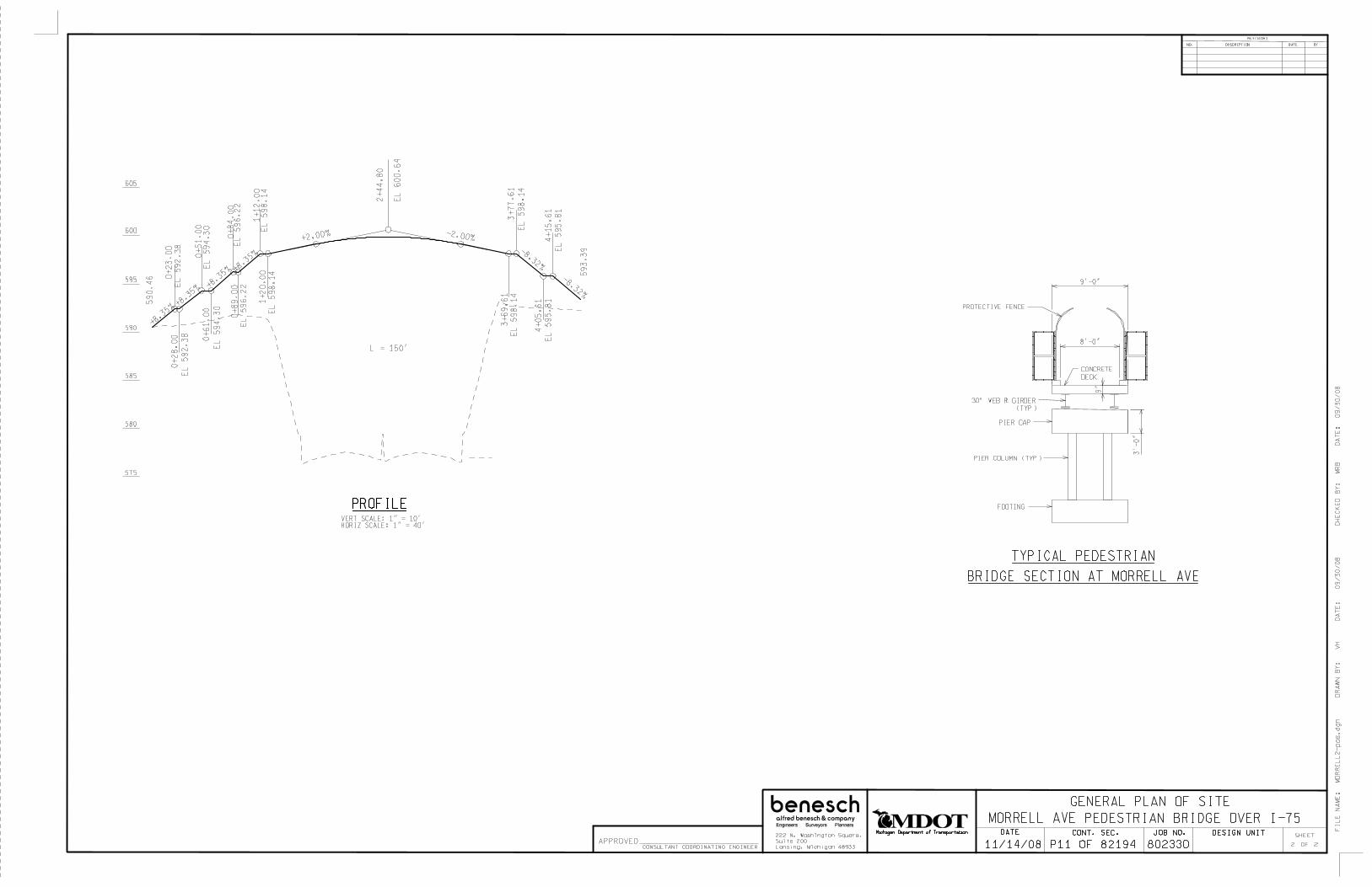
GENERAL PLAN OF SITE
VERT SCALE: 1" = 10’HORIZ SCALE: 1" = 40’
CONCRETE
DECK
PROTECTIVE FENCE
PIER CAP
PIER COLUMN (TYP)
3’-0
"
8’-0"
9"
FOOTING
TYPICAL PEDESTRIAN
BRIDGE SECTION AT MORRELL AVE
605
600
595
590
585
580
CH
EC
KE
D B
Y:
MR
B D
AT
E:
09/3
0/0
8D
RA
WN
BY
: V
H D
AT
E:
09/3
0/0
8
2 2
575
MORRELL AVE PEDESTRIAN BRIDGE OVER I-75
9’-0"
FIL
E N
AM
E:
MO
RR
EL
L2-p
os.
dgn
PROFILE
P11 OF 82194
30" WEB > GIRDER
(TYP)
0+
23
.00
EL
592.3
8
+8.3
4% +0.00%
59
0.4
6
0+
28
.00
EL
592.3
8
+8.3
5%
0+
51
.00
EL
594.3
0
+8.3
5%
0+
61
.00
EL
59
4.3
0
+8.3
5%
0+
84
.00
EL
596.2
2
+8.3
5%
0+
89
.00
EL
596.2
2
+8.3
5%
1+
12
.00
EL
598.1
4
+8.3
5%
1+
20
.00
EL
598.1
4
2+
44
.80
EL
600.6
4
+2.00% -2.00%
L = 150’
3+
69
.61
EL
598.1
4
+0.00%
3+
77
.61
EL
598.1
4
-8.32%
4+
05
.61
EL
595.8
1
-8.32%
+0.00%
4+
15
.61
EL
595.8
1
-8.34%
593.3
9
Michigan Department of Transportation
11/14/08
CONT. SEC.DATE JOB NO. DESIGN UNITSHEET
REVISIONS
DESCRIPTIONNO. BYDATE
222 N. Washington Square,
Suite 200
Lansing, Michigan 48933
APPROVEDCONSULTANT COORDINATING ENGINEER 802330 OF

SITUATION PLANSCALE: 1" = 40’
GENERAL PLAN OF SITE
McKINSTRY AVE PEDESTRIAN BRIDGE OVER I-75
STA 0+00.00 (BRIDGE)
STA 6+48.58 (BRIDGE)
COMCAST COAXIAL (AG)
DETROIT EDISON
EX SAN 5’-9" CYL (DWSD)
DP
L
REF PT 2
STA 3+16.03 (BRIDGE)
STA 203+24.63 (I-75)
MICHCON 4" STEEL
120 k
V &
CO
NT
RO
L C
AB
LE
IT
C
EX
WA
TE
R 6
" (DW
SD
)
MIC
HC
ON
8" S
TE
EL
MIC
HC
ON
16" S
TE
EL
EX WATER 6" (DWSD)
ELEVATION
VERT SCALE: 1" = 10’HORIZ SCALE: 1" = 40’
EXP EXP
FIX
209’-0"
109’-0"
100’-0"
THE DESIGN OF THIS STRUCTURE IS BASED ON CURRENT AASHTO STANDARD SPECIFICATIONS
FOR HIGHWAY BRIDGES H-10 LOADING. LIVE LOAD PLUS IMPACT DEFLECTION DOES NOT EXCEED
1/500 OF SPAN LENGTH.
THE WORK COVERED BY THESE PLANS INCLUDES REMOVAL OF THE EXISTING BRIDGE, CONSTRUCTION
OF THE PROPOSED BRIDGE, AND PLACING SLOPE PAVING TO THE LIMITS SHOWN. ALL OTHER WORK IS
INCLUDED IN THE ROAD PLANS THAT ARE A PART OF THIS CONTRACT.
THE CONTRACTOR SHALL LOCATE ALL UNDERGROUND UTILITIES PRIOR TO STARTING WORK AND SHALL
CONDUCT HIS OPERATIONS IN SUCH A MANNER AS TO ENSURE THAT THOSE UTILITIES NOT REQUIRING
RELOCATION WILL NOT BE DISTURBED.
PLAN ELEVATIONS REFER TO NAVD 88 DATUM.
MEASURES SHALL BE TAKEN TO PREVENT DEBRIS FROM FALLING FROM THE STRUCTURE.
THIS BRIDGE IS WITHIN MDOT RIGHT-OF-WAY.
THE CONTRACTOR SHALL NOTIFY EACH UTILITY COMPANY 48 HOURS IN ADVANCE OF WORK IMPACTING
THAT COMPANY’S CONDUITS OR FACILITIES.
THE VERTICAL MINIMUM CLEARANCE COMPUTATIONS WERE PREPARED BY PARSONS ENGINEERS.
NOTES
COMCAST COAXIAL (AG)DPL
EX WATER 12" (DWSD)MICHCON 4" PLASTIC
EX SAN 6’-0" CYL (DWSD)
DETROIT EDISON
WITNESSES
UTILITIES
TO BE CONFIRMED
BENCHMARKS
BM 312
DESCRIPTION: CHISELED ’X’ ON THE NW BOLT OF LIGHT POLE ON THE SOUTH SIDE OF
FORT STREET 30 FEET EAST OF THE VISITOR AND EMPLOYEE ENTRANCE TO "BRIDGE WATER
INETRIORS" BUILDING #4617.
ELEVATION: 585.33
BM 313
DESCRIPTION: CHISELED ’X’ ON THE NW BOLT OF A LIGHT POLE ON THE SOUTH SIDE OF
FORT STREET 200 FEET WEST OF "MOTOR CITY INTERMODAL DISTRIBUTION" BUILDING #4005.
ELEVATION: 593.16
CONTROL PT# 735
DESCRIPTION: SET MAG NAIL IN CENTER
OF AN AERIAL TARGET ON AN ASPHALT
APRON SOUTH OF FISHER ST.
WITNESSES:
1. N10^E 6.00’ MANHOLE
2. N10^W 3.00’ BACK OF CURB
3. N90^E 14.00’ ONE WAY SIGN
4. S60^W 8.00’ FENCE CORNER
CONTROL PT# 781
DESCRIPTION: SET MAG NAIL IN CENTER
OF AN AERIAL TARGET ON THE SOUTH
SHOULDER OF THE OFF-RAMP FROM I-75 N
AT EXIT 47A.
WITNESSES:
1. N30^W 2.00’ BACK OF CURB
2. S30^E 39.00’ FENCE
3. S30^W 21.00’ END OF BARRIER
4. N60^E 72.00’ LIGHT POLE
EXISTING STRUCTURE
NONE
605
600
595
590
585
580
REF LINE 1 REF LINE 3
\ I-75 &
REF LINE 2
BOT/FTG
EL 583.00BOT/FTG
EL 581.00BOT/FTG
EL 580.00
BOT/FTG
EL 575.50
575
BOT/FTG
EL 580.50
REF PT 1REF PT 3
17’-0"
MIN
VE
RT
CL
R
CH
EC
KE
D B
Y:
MR
B D
AT
E:
09/2
2/0
8D
RA
WN
BY
: V
H D
AT
E:
09/1
8/0
8
FIL
E N
AM
E:
MsK
instr
y1-p
os.d
gn
STA 1+88.07 (BRIDGE)
STA 4+36.64 (BRIDGE)
1 2
RETAINING WALL
\ I-75
89^2
4’3
0"
90^5
’55"
90^2
6’5
7"
BOT/FTG
EL 586.50
19’-0"
34’-6"
30’-0"
32’-6"
32’-6"
30’-0"
28’-6"
19’-0" 38’-6" 34’-0" 36’-6" 37’-6" 35’-0" 32’-6"
BENCH (TYP)
EDGE OF
PAVEMENT
EDGE OF
PAVEMENT
PROPOSED STRUCTURE
P12 OF 82194
P12 OF 82194
28" WEB
> GIRDER
35’-3"
MIN CLR
17’-3"
MIN CLR
11’-4"
MIN CLR
11’-4"
MIN CLR
202
203
204
205
206
207
16
17
18
19
20
21
22
1201
1202
1203
1204
1205
1206
1207
0
1
2 3 4
5 6
Michigan Department of Transportation
11/14/08
CONT. SEC.DATE JOB NO. DESIGN UNITSHEET
REVISIONS
DESCRIPTIONNO. BYDATE
222 N. Washington Square,
Suite 200
Lansing, Michigan 48933
APPROVEDCONSULTANT COORDINATING ENGINEER 802330 OF

GENERAL PLAN OF SITE
McKINSTRY AVE PEDESTRIAN BRIDGE OVER I-75
VERT SCALE: 1" = 10’HORIZ SCALE: 1" = 40’
CONCRETE
DECK
PROTECTIVE FENCE
PIER CAP
PIER COLUMN (TYP)
3’-0
"
14-0
15’-0"
9"
FOOTING
TYPICAL PEDESTRIAN
BRIDGE SECTION AT McINSTRY AVE
605
600
595
590
585
580
CH
EC
KE
D B
Y:
MR
B D
AT
E:
09/2
2/0
8D
RA
WN
BY
: V
H D
AT
E:
09/1
8/0
8
FIL
E N
AM
E:
McK
instr
y2-p
os.d
gn
2 2
PROFILE
P12 OF 82194
28" WEB > GIRDER
(TYP)
0+
26
.00
EL
589.2
9
587.1
2
0+
31
.00
EL
589.2
9
0+
56
.00
EL
591.3
7
+8.3
2%
0+
61
.00
EL
591.3
7
0+
86
.00
EL
593.4
5
+8.3
2%
0+
96
.00
EL
593.4
5
1+
21
.00
EL
595.5
3
+8.3
2%
1+
26
.00
EL
595.5
3
+8.3
2%
1+
51
.00
EL
597.6
1+8.3
2%
1+
56
.00
EL
597.6
1
1+
81
.00
EL
599.6
9
+8.3
2%
1+
95
.00
EL
599.6
9
3+
11.2
8
EL
602.0
2
+2.00% -2.00%
L = 150’
4+
27.5
7
EL
599.6
94+
41.5
7
EL
599.6
9
-8.34%
4+
70.5
7
EL
597.2
74+
75.5
7
EL
597.2
7 -8.34%
5+
04.5
7
EL
594.8
5
-8.34%
5+
09.5
7
EL
594.8
5
-8.34%
5+
38.5
7
EL
592.4
3
-8.34%
5+
48.5
7
EL
592.4
3
-8.33%
5+
78.5
7
EL
589.9
3
-8.33%
5+
83.5
7
EL
589.9
3
-8.33%
6+
13.5
7
EL
587.4
3
-8.33%
6+
18.5
7
EL
587.4
3
584.9
3
Michigan Department of Transportation
11/14/08
CONT. SEC.DATE JOB NO. DESIGN UNITSHEET
REVISIONS
DESCRIPTIONNO. BYDATE
222 N. Washington Square,
Suite 200
Lansing, Michigan 48933
APPROVEDCONSULTANT COORDINATING ENGINEER 802330 OF

111
112
113
114 115
116 117
118 119 120 121 122 123 124 125 126 127 128 129 130 131 132 133 134
BRIDGE DESCRIPTION
FORT ST
SP
RIN
GW
EL
LS
ST
SB I-75
NB I-75
WALL L
WALL A
WALL M
WALL N
WALL B
CH
EC
KE
D B
Y:
D
AT
E:
DR
AW
N B
Y:
D
AT
E:
FIL
E N
AM
E:
CO
RR
EC
TE
D B
Y:
D
AT
E:
GL
INN
AN
ST
SO
LV
AY
ST
CE
NT
RA
L S
T
SERVICE DR
RAMP I
RAMP L
SERVICE DR
RAMP K
RAMP J
PROPOSED STRUCTURE S07 OF 82194
100 SCALE
RETAINING WALL PLAN
MA
TC
H L
INE
ST
A 1
35
+0
0
WALL C
PROPOSED STRUCTURE P01 OF 82194
Michigan Department of Transportation
11/14/08
CONT. SEC.DATE JOB NO. DESIGN UNITSHEET
REVISIONS
DESCRIPTIONNO. BYDATE
222 N. Washington Square,
Suite 200
Lansing, Michigan 48933
APPROVEDCONSULTANT COORDINATING ENGINEER 802330 OF
SPRINGWELLS AVE.
SOLVAY ST
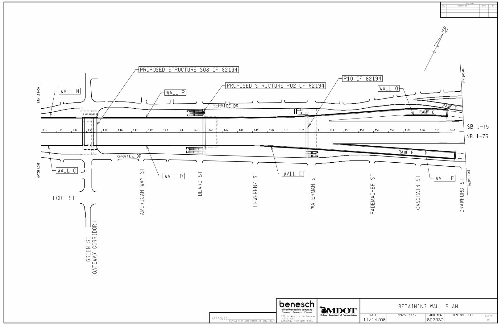
135 136 137 138 139 140 141 142 143 144 145 146 147 148 149 150 151 152 153 154 155 156 157 158 159 160 161 162
BRIDGE DESCRIPTION
WA
TE
RM
AN
ST
FORT ST
LE
WE
RE
NZ
ST
BE
AR
D S
T
CA
SG
RA
IN S
T
RA
DE
MA
CH
ER
ST
CR
AW
FO
RD
ST
SB I-75
NB I-75
WALL C
WALL D
WALL P
WALL EWALL F
WALL QG
RE
EN
ST
(GA
TE
WA
Y C
OR
RID
OR
)
AM
ER
ICA
N W
AY
ST
SERVICE DR
SERVICE DR
PROPOSED STRUCTURE S08 OF 82194
P10 OF 82194
RAMP C
RAMP G
RAMP B
RETAINING WALL PLAN
ST
A 1
35
+0
0M
AT
CH
LIN
E
WALL N
MA
TC
H L
INE
ST
A 1
63+
00
PROPOSED STRUCTURE P02 OF 82194
Michigan Department of Transportation
11/14/08
CONT. SEC.DATE JOB NO. DESIGN UNITSHEET
REVISIONS
DESCRIPTIONNO. BYDATE
222 N. Washington Square,
Suite 200
Lansing, Michigan 48933
APPROVEDCONSULTANT COORDINATING ENGINEER 802330 OF
GREEN AVE. BEARD ST WATERMAN ST

DR
AG
OO
N S
T
JUN
CT
ION
ST
CA
MP
BE
LL
ST
CA
VA
LR
Y S
T
LIV
ER
NO
IS A
VE
MIL
ITA
RY
ST
DETROIT
SAVINGS
BANK
SB I-75
NB I-75
WALL R
WALL G
WALL S
WALL Z
WALL T
WALL AA
WALL H
WALL U
WALL Y
WALL X
165 166
167 168
169 170
171 172
173 174
175 176
177 178
179 180
181 182
183 184 185
164
188 189 190 191 192 186 187
RAM
P C
SERVICE DR
PROPOSED STRUCTURE
S10 OF 82194
100 SCALE
RAMP G
RAMP B
RAMP E
RAMP F
WALL V
RA
MP
D
RA
MP
A
CELERON ST
CH
EC
KE
D B
Y:
D
AT
E:
DR
AW
N B
Y:
D
AT
E:
FIL
E N
AM
E:
CO
RR
EC
TE
D B
Y:
D
AT
E:
RETAINING WALL PLAN
MA
TC
H L
INE
ST
A 1
63+
00
MA
TC
H L
INE
S
TA
192+
00
163
BERWALTMANOR APTS
Michigan Department of Transportation
11/14/08
CONT. SEC.DATE JOB NO. DESIGN UNITSHEET
REVISIONS
DESCRIPTIONNO. BYDATE
222 N. Washington Square,
Suite 200
Lansing, Michigan 48933
APPROVEDCONSULTANT COORDINATING ENGINEER 802330 OF
LIVERNOIS AVE.

MO
RR
EL
L S
T.
McK
INS
TR
Y S
T.
LA
NS
ING
ST
FE
RD
INA
ND
ST
FORT ST
SB I-75
NB I-75
WALL U
WALL K
192 193 194 195 196 197 198 199 200 201 202 203 204 205 206 207 208 209 210 211 212 213 214
WALL W
CELERON ST
RAMP D
LAFAYETTE BLVD
CL
AR
K A
VE
PROPOSED STRUCTURE S12 0F 82194
WALL J
CH
EC
KE
D B
Y:
D
AT
E:
DR
AW
N B
Y:
D
AT
E:
FIL
E N
AM
E:
CO
RR
EC
TE
D B
Y:
D
AT
E:
WALL H
RETAINING WALL PLAN
MA
TC
H L
INE
ST
A 1
92+
00
WALL V
PROPOSED STRUCTURE P11 0F 82194PROPOSED STRUCTURE P12 0F 82194
Michigan Department of Transportation
11/14/08
CONT. SEC.DATE JOB NO. DESIGN UNITSHEET
REVISIONS
DESCRIPTIONNO. BYDATE
222 N. Washington Square,
Suite 200
Lansing, Michigan 48933
APPROVEDCONSULTANT COORDINATING ENGINEER 802330 OF
CLARK ST.
MORRELL ST. McKINSTRY ST.

Appendix B
Cost Estimates (All Structures)
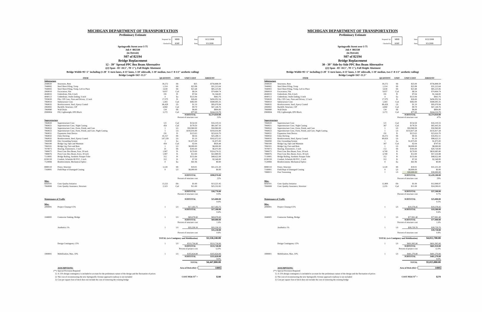
MICHIGAN DEPARTMENT OF TRANSPORTATIONPreliminary Estimate
Prepared by: MRB Date: 8/22/2008
Checked by: KMP Date: 9/5/2008Springwells Street over I-75
Job # 802330(in Detroit)
S07 of 82194Bridge Replacement
12 - 39" Spread PPC Box Beam Alternative ((2) Span - 85'-10.5", 78'-1"), Full Height Abutment
Bridge Length=163'-11.5"ITEM QUANTITY UNIT UNIT COST AMOUNT
Substructure2040020 Structures, Rem 30,272 Sft $25 $756,808.597040002 Steel Sheet Piling, Temp 1,314 Sft $23.98 $31,513.647040003 Steel Sheet Piling, Temp, Left in Place 3,630 Sft $23.48 $85,225.062060010 Excavation, Fdn 9,037 Cyd $8.24 $74,464.744040033 Underdrain, Fdn, 6 inch 191 Ft $7.04 $1,344.834040113 Underdrain, Outlet Ending, 6 inch 4 Ea $115.94 $463.767050020 Pile, CIP Conc, Furn and Driven, 12 inch 17,575 Ft $26.00 $456,952.547060010 Substructure Conc 1,443 Cyd $402.00 $580,005.357060035 Reinforcement, Steel, Epoxy Coated 86,428 Lb $1.10 $95,070.942060002 Backfill, Structure, CIP 4,860 Cyd $9.70 $47,146.767060080 Wall Drain 134 Sft $6.00 $804.00Z000004 Fill, Lightweight, EPS Block 3,172 Cyd $77.00 $244,210.79
SUBTOTAL $2,374,010.00Percent of structure cost 53%
Superstructure7060020 Superstructure Conc 121 Cyd $134.50 $16,319.337060021 Superstructure Conc, Night Casting 454 Cyd $178.50 $81,067.107060022 Superstructure Conc, Form, Finish, and Cure 1 LS $50,960.00 $50,960.007060023 Superstructure Conc, Form, Finish, and Cure, Night Casting 1 LS $193,016.90 $193,016.907060031 Expansion Joint Device 191 Ft $123.63 $23,616.707060032 False Decking 45,157 Sft $0.56 $25,288.117060035 Reinforcement, Steel, Epoxy Coated 147,339 Lb $1.10 $162,072.637060090 Elec Grounding System 1 Ea $1,875.00 $1,875.007060100 Bridge Ltg, Oper and Maintain 454 Cyd $2.04 $926.487060101 Bridge Ltg, Furn and Rem 1 LS $8,000.00 $8,000.007070073 Bearing, Elastomeric, 3 inch 35 Sft $185.00 $6,475.007080075 Prest Conc Box Beam, Furn, 39 inch 1,907 Ft $170.00 $324,274.327080076 Prest Conc Box Beam, Erect, 39 inch 1,907 Ft $12.00 $22,889.957110005 Bridge Railing, Aesthetic Parapet Tube 312 Ft $155.84 $48,622.088190159 Conduit, Schedule 80 PVC, 3 inch 312 Ft $7.50 $2,340.007120084 Reinforcement, Mechanical Splice 0 Ea $41.96 $0.00
8080110 Fence, Structure 3,120 Sft $10.01 $31,231.207160001 Field Repr of Damaged Coating 0 LS $8,000.00 $0.00
SUBTOTAL $998,970.00Percent of structure cost 22%
Misc.6050101 Conc Quality Initiative 13,221 Dlr $1.00 $13,221.457060008 Conc Quality Assurance, Structure 2,323 Cyd $11.00 $25,552.82
SUBTOTAL $38,770.00Percent of structure cost 0.9%
Maintenance of Traffic SUBTOTAL $25,000.000.6%
Misc.2090001 Project Cleanup 0.5% 1 LS $17,183.75 $17,183.75
SUBTOTAL $17,180.000.4%
1040005 Contractor Staking, Bridge 1 LS $69,078.60 $69,078.60SUBTOTAL $69,080.00
Percent of structure cost 1.6%
Aesthetics 1% 1 LS $35,230.10 $35,230.10$35,230.00
Percent of structure cost 0.8%
TOTAL (w/o Contigency and Mobilization) $3,558,240.00
Design Contingency 15% 1 LS $533,736.00 $533,736.00SUBTOTAL $533,740.00
Percent of project cost 12.0%
1000001 Mobilization, Max, 10% 1 LS $355,824.00 $355,824.00SUBTOTAL $355,820.00
8.0%TOTAL $4,447,800.00
ASSUMPTIONS: Area of Deck (ft2) = 14885(**) Special Provision Required
1) A 15% design contingency is included to account for the preliminary nature of the design and the fluctuation of prices2) The cost of reconstructing the new Springwells Avenue approach roadway is not included COST PER FT2 = $2403) Cost per square foot of deck does not include the cost of removing the existing bridge
Bridge Width=95'-5" including (1-20' U-turn lanes, 4-13' lanes, 1-10' sidewalk, 1-10' median, two 1'-8 1/2" aesthetic railing)
MICHIGAN DEPARTMENT OF TRANSPORTATIONPreliminary Estimate
Prepared by: MRB Date: 8/22/2008
Checked by: KMP Date: 9/5/2008Springwells Street over I-75
Job # 802330(in Detroit)
S07 of 82194Bridge Replacement
30 - 39" Side-by-Side PPC Box Beam Alternative ((2) Span - 85'-10.5", 78'-1"), Full Height Abutment
Bridge Length=163'-11.5"ITEM QUANTITY UNIT UNIT COST AMOUNT
Substructure2040020 Structures, Rem 30,272 Sft $25.00 $756,808.597040002 Steel Sheet Piling, Temp 1,314 Sft $23.98 $31,513.647040003 Steel Sheet Piling, Temp, Left in Place 3,630 Sft $23.48 $85,225.062060010 Excavation, Fdn 9,037 Cyd $8.24 $74,464.744040033 Underdrain, Fdn, 6 inch 191 Ft $7.04 $1,344.834040113 Underdrain, Outlet Ending, 6 inch 4 Ea $115.94 $463.767050020 Pile, CIP Conc, Furn and Driven, 12 inch 17,575 Ft $26.00 $456,952.547060010 Substructure Conc 1,443 Cyd $402.00 $580,005.357060035 Reinforcement, Steel, Epoxy Coated 86,428 Lb $1.10 $95,070.942060002 Backfill, Structure, CIP 4,860 Cyd $9.70 $47,146.767060080 Wall Drain 134 Sft $6.00 $804.00Z000004 Fill, Lightweight, EPS Block 3,172 Cyd $77.00 $244,210.79
SUBTOTAL $2,374,010.00Percent of structure cost 47%
Superstructure7060020 Superstructure Conc 121 Cyd $134.50 $16,319.337060021 Superstructure Conc, Night Casting 367 Cyd $178.50 $65,443.267060022 Superstructure Conc, Form, Finish, and Cure 1 LS $50,960.00 $50,960.007060023 Superstructure Conc, Form, Finish, and Cure, Night Casting 1 LS $155,817.28 $155,817.287060031 Expansion Joint Device 191 Ft $123.63 $23,616.707060032 False Decking 30,272 Sft $0.56 $16,952.517060035 Reinforcement, Steel, Epoxy Coated 89,659 Lb $1.10 $98,625.317060090 Elec Grounding System 1 Ea $1,875.00 $1,875.007060100 Bridge Ltg, Oper and Maintain 367 Cyd $2.04 $747.927060101 Bridge Ltg, Furn and Rem 1 LS $8,000.00 $8,000.007070073 Bearing, Elastomeric, 3 inch 112 Sft $185.00 $20,720.007080075 Prest Conc Box Beam, Furn, 39 inch 4,769 Ft $170.00 $810,685.807080076 Prest Conc Box Beam, Erect, 39 inch 4,769 Ft $12.00 $57,224.887110005 Bridge Railing, Aesthetic Parapet Tube 312 Ft $155.84 $48,622.088190159 Conduit, Schedule 80 PVC, 3 inch 312 Ft $7.50 $2,340.007120084 Reinforcement, Mechanical Splice 0 Ea $41.96 $0.00
8080110 Fence, Structure 3,120 Sft $10.01 $31,231.207160001 Field Repr of Damaged Coating 0 LS $8,000.00 $0.007080015 Post Tensioning 1 LS $30,000.00 $30,000.00
SUBTOTAL $1,439,180.00Percent of structure cost 29%
Misc.6050101 Conc Quality Initiative 12,909 Dlr $1.00 $12,908.977060008 Conc Quality Assurance, Structure 2,235 Cyd $11.00 $24,590.01
SUBTOTAL $37,500.00Percent of structure cost 0.7%
Maintenance of Traffic SUBTOTAL $25,000.000.5%
Misc.2090001 Project Cleanup 0.5% 1 LS $19,378.45 $19,378.45
SUBTOTAL $19,380.000.4%
1040005 Contractor Staking, Bridge 1 LS $77,901.40 $77,901.40SUBTOTAL $77,900.00
Percent of structure cost 1.6%
Aesthetics 1% 1 LS $39,729.70 $39,729.70$39,730.00
Percent of structure cost 0.8%
TOTAL (w/o Contigency and Mobilization) $4,012,700.00
Design Contingency 15% 1 LS $601,905.00 $601,905.00SUBTOTAL $601,910.00
Percent of project cost 12.0%
1000001 Mobilization, Max, 10% 1 LS $401,270.00 $401,270.00SUBTOTAL $401,270.00
8.0%TOTAL $5,015,880.00
ASSUMPTIONS: Area of Deck (ft2) = 14885(**) Special Provision Required
1) A 15% design contingency is included to account for the preliminary nature of the design and the fluctuation of prices2) The cost of reconstructing the new Springwells Avenue approach roadway is not included COST PER FT2 = $2793) Cost per square foot of deck does not include the cost of removing the existing bridge
Bridge Width=95'-5" including (1-20' U-turn lanes, 4-13' lanes, 1-10' sidewalk, 1-10' median, two 1'-8 1/2" aesthetic railing)

MICHIGAN DEPARTMENT OF TRANSPORTATIONPreliminary Estimate
Prepared by: MRB Date: 8/22/2008
Checked by: KMP Date: 9/5/2008Springwells Street over I-75
Job # 802330(in Detroit)
S07 of 82194Bridge Replacement
34" Web Steel Plate Girder Alternative ((2) Span - 85'-10.5", 78'-1"), Full Height Abutment
Bridge Length=163'-11.5"ITEM QUANTITY UNIT UNIT COST AMOUNT
Substructure2040020 Structures, Rem 30,272 Sft $25 $756,808.597040002 Steel Sheet Piling, Temp 1,314 Sft $23.98 $31,513.647040003 Steel Sheet Piling, Temp, Left in Place 3,630 Sft $23.48 $85,225.062060010 Excavation, Fdn 9,037 Cyd $8.24 $74,464.744040033 Underdrain, Fdn, 6 inch 191 Ft $7.04 $1,344.834040113 Underdrain, Outlet Ending, 6 inch 4 Ea $115.94 $463.767050020 Pile, CIP Conc, Furn and Driven, 12 inch 17,575 Ft $26.00 $456,952.547060010 Substructure Conc 1,443 Cyd $402.00 $580,005.357060035 Reinforcement, Steel, Epoxy Coated 86,428 Lb $1.10 $95,070.942060002 Backfill, Structure, CIP 4,860 Cyd $9.70 $47,146.767060080 Wall Drain 134 Sft $6.00 $804.00Z000004 Fill, Lightweight, EPS Block 3,172 Cyd $77.00 $244,210.79
SUBTOTAL $2,374,010.00Percent of structure cost 44%
Superstructure7060020 Superstructure Conc 121 Cyd $134.50 $16,319.337060021 Superstructure Conc, Night Casting 443 Cyd $178.50 $79,018.757060022 Superstructure Conc, Form, Finish, and Cure 1 LS $50,960.00 $50,960.007060023 Superstructure Conc, Form, Finish, and Cure, Night Casting 1 LS $188,139.89 $188,139.897060031 Expansion Joint Device 191 Ft $123.63 $23,616.707060032 False Decking 45,157 Sft $0.56 $25,288.117060035 Reinforcement, Steel, Epoxy Coated 147,339 Lb $1.10 $162,072.637060090 Elec Grounding System 1 Ea $1,875.00 $1,875.007060100 Bridge Ltg, Oper and Maintain 443 Cyd $2.04 $903.077060101 Bridge Ltg, Furn and Rem 1 LS $8,000.00 $8,000.007070073 Bearing, Elastomeric, 3 inch 38 Sft $185.00 $7,030.007070007 Structural Steel, Plate, Furn and Fab 541,087 Lb $1.87 $1,011,832.197070008 Structural Steel, Plate, Erect 541,087 Lb $0.18 $97,395.617110005 Bridge Railing, Aesthetic Parapet Tube 312 Ft $155.84 $48,622.088190159 Conduit, Schedule 80 PVC, 3 inch 312 Ft $7.50 $2,340.007120084 Reinforcement, Mechanical Splice Ea $41.96 $0.007070080 Shear Developers 1 LS $24,023.69 $24,023.698080110 Fence, Structure 3,120 Sft $10.01 $31,231.207160001 Field Repr of Damaged Coating 0 LS $8,000.00 $0.00
SUBTOTAL $1,778,670.00Percent of structure cost 33%
Misc.6050101 Conc Quality Initiative 13,180 Dlr $1.00 $13,180.487060008 Conc Quality Assurance, Structure 2,312 Cyd $11.00 $25,426.60
SUBTOTAL $38,610.00Percent of structure cost 0.7%
Maintenance of Traffic SUBTOTAL $25,000.000.5%
Misc.2090001 Project Cleanup 0.5% 1 LS $21,081.45 $21,081.45
SUBTOTAL $21,080.000.4%
1040005 Contractor Staking, Bridge 1 LS $84,747.40 $84,747.40SUBTOTAL $84,750.00
Percent of structure cost 1.6%
Aesthetics 1% 1 LS $43,221.20 $43,221.20$43,220.00
Percent of structure cost 0.8%
TOTAL (w/o Contigency and Mobilization) $4,365,340.00
Design Contingency 15% 1 LS $654,801.00 $654,801.00SUBTOTAL $654,800.00
Percent of project cost 12.0%
1000001 Mobilization, Max, 10% 1 LS $436,534.00 $436,534.00SUBTOTAL $436,530.00
Percent of project cost 8.0%
TOTAL $5,456,670.00
ASSUMPTIONS: Area of Deck (ft2) = 14885(**) Special Provision Required
1) A 15% design contingency is included to account for the preliminary nature of the design and the fluctuation of prices2) The cost of reconstructing the new Springwells Avenue approach roadway is not included COST PER FT2 = $3083) Cost per square foot of deck does not include the cost of removing the existing bridge
Bridge Width=95'-5" including (1-20' U-turn lanes, 4-13' lanes, 1-10' sidewalk, 1-10' median, two 1'-8 1/2" aesthetic railing)
MICHIGAN DEPARTMENT OF TRANSPORTATIONPreliminary Estimate
Prepared by: MRB Date: 8/26/2008
Checked by: KMP Date: 9/5/2008Green Ave. over I-75
Job # 802330(in Detroit)
S08 of 82194Bridge Replacement
12 - 42" Spread PPC Box Beam Alternative ((2) Span - 102'-0", 90'-0"), Full Height Abutment
Bridge Length=192'-0"ITEM QUANTITY UNIT UNIT COST AMOUNT
Substructure2040020 Structures, Rem 19,261 Sft $25.00 $481,520.837040002 Steel Sheet Piling, Temp 1,313 Sft $23.98 $31,485.747040003 Steel Sheet Piling, Temp, Left in Place 0 Sft $23.48 $0.002060010 Excavation, Fdn 3,717 Cyd $8.24 $30,628.084040033 Underdrain, Fdn, 6 inch 191 Ft $7.04 $1,343.474040113 Underdrain, Outlet Ending, 6 inch 4 Ea $115.94 $463.767050020 Pile, CIP Conc, Furn and Driven, 12 inch 19,745 Ft $26.00 $513,366.437060010 Substructure Conc 1,442 Cyd $402.00 $579,581.467060035 Reinforcement, Steel, Epoxy Coated 86,362 Lb $1.10 $94,998.082060002 Backfill, Structure, CIP 4,858 Cyd $9.70 $47,119.717060080 Wall Drain 134 Sft $6.00 $804.00Z000004 Fill, Lightweight, EPS Block 3,169 Cyd $77.00 $243,980.67
SUBTOTAL $2,025,290.00Percent of structure cost 48%
Superstructure7060020 Superstructure Conc 143 Cyd $134.50 $19,248.447060021 Superstructure Conc, Night Casting 549 Cyd $178.50 $98,050.497060022 Superstructure Conc, Form, Finish, and Cure 1 LS $60,106.67 $60,106.677060023 Superstructure Conc, Form, Finish, and Cure, Night Casting 1 LS $233,453.55 $233,453.557060031 Expansion Joint Device 191 Ft $123.63 $23,592.737060032 False Decking 36,818 Sft $0.56 $20,617.807060035 Reinforcement, Steel, Epoxy Coated 173,784 Lb $1.10 $191,162.587060090 Elec Grounding System 1 Ea $1,875.00 $1,875.007060100 Bridge Ltg, Oper and Maintain 549 Cyd $2.04 $1,120.587060101 Bridge Ltg, Furn and Rem 1 LS $8,000.00 $8,000.007070073 Bearing, Elastomeric, 3 inch 42 Sft $185.00 $7,770.007080081 Prest Conc Box Beam, Furn, 42 inch 2,244 Ft $176.63 $396,357.727080082 Prest Conc Box Beam, Erect, 42 inch 2,244 Ft $12.00 $26,928.007110005 Bridge Railing, Aesthetic Parapet Tube 368 Ft $155.84 $57,349.128190159 Conduit, Schedule 80 PVC, 3 inch 368 Ft $7.50 $2,760.007120084 Reinforcement, Mechanical Splice 0 Ea $41.96 $0.00
8080110 Fence, Structure 3,680 Sft $10.01 $36,836.807160001 Field Repr of Damaged Coating 0 LS $8,000.00 $0.00
SUBTOTAL $1,185,230.00Percent of structure cost 28%
Misc.6050101 Conc Quality Initiative 13,553 Dlr $1.00 $13,552.647060008 Conc Quality Assurance, Structure 2,445 Cyd $11.00 $26,894.12
SUBTOTAL $40,450.00Percent of structure cost 1.0%
Maintenance of Traffic SUBTOTAL $0.000.0%
Misc.2090001 Project Cleanup 0.5% 1 LS $16,254.85 $16,254.85
SUBTOTAL $16,250.000.4%
1040005 Contractor Staking, Bridge 1 LS $65,344.40 $65,344.40SUBTOTAL $65,340.00
Percent of structure cost 1.6%
Aesthetics 1% 1 LS $33,325.60 $33,325.60$33,330.00
Percent of structure cost 0.8%
TOTAL (w/o Contigency and Mobilization) $3,365,890.00
Design Contingency 15% 1 LS $504,883.50 $504,883.50SUBTOTAL $504,880.00
Percent of project cost 12.0%
1000001 Mobilization, Max, 10% 1 LS $336,589.00 $336,589.00SUBTOTAL $336,590.00
Percent of project cost 8.0%
TOTAL $4,207,360.00
ASSUMPTIONS: Area of Deck (ft2) = 17557(**) Special Provision Required
1) A 15% design contingency is included to account for the preliminary nature of the design and the fluctuation of prices2) The cost of reconstructing the new Green Avenue approach roadway is not included COST PER FT2 = $2083) Cost per square foot of deck does not include the cost of removing the existing bridge
Bridge Width=95'-5" including (1-20' U-turn lanes, 4-13' lanes, 1-10' sidewalk, 1-10' median, two 1'-8 1/2" aesthetic railing)

MICHIGAN DEPARTMENT OF TRANSPORTATIONPreliminary Estimate
Prepared by: MRB Date: 8/26/2008
Checked by: KMP Date: 9/5/2008Green Ave. over I-75
Job # 802330(in Detroit)
S08 of 82194Bridge Replacement
23 - 39" Side-by-Side PPC Box Beam Alternative ((2) Span - 102'-0", 90'-0"), Full Height Abutment
Bridge Length=192'-0"ITEM QUANTITY UNIT UNIT COST AMOUNT
Substructure2040020 Structures, Rem 19,261 Sft $25.00 $481,520.837040002 Steel Sheet Piling, Temp 1,313 Sft $23.98 $31,485.747040003 Steel Sheet Piling, Temp, Left in Place 0 Sft $23.48 $0.002060010 Excavation, Fdn 3,717 Cyd $8.24 $30,628.084040033 Underdrain, Fdn, 6 inch 191 Ft $7.04 $1,343.474040113 Underdrain, Outlet Ending, 6 inch 4 Ea $115.94 $463.767050020 Pile, CIP Conc, Furn and Driven, 12 inch 19,745 Ft $26.00 $513,366.437060010 Substructure Conc 1,442 Cyd $402.00 $579,581.467060035 Reinforcement, Steel, Epoxy Coated 86,362 Lb $1.10 $94,998.082060002 Backfill, Structure, CIP 4,858 Cyd $9.70 $47,119.717060080 Wall Drain 134 Sft $6.00 $804.00Z000004 Fill, Lightweight, EPS Block 3,169 Cyd $77.00 $243,980.67
SUBTOTAL $2,025,290.00Percent of structure cost 45%
Superstructure7060020 Superstructure Conc 143 Cyd $134.50 $19,248.447060021 Superstructure Conc, Night Casting 432 Cyd $178.50 $77,024.257060022 Superstructure Conc, Form, Finish, and Cure 1 LS $60,106.67 $60,106.677060023 Superstructure Conc, Form, Finish, and Cure, Night Casting 1 LS $183,391.07 $183,391.077060031 Expansion Joint Device 191 Ft $123.63 $23,592.737060032 False Decking 19,261 Sft $0.56 $10,786.077060035 Reinforcement, Steel, Epoxy Coated 105,752 Lb $1.10 $116,327.297060090 Elec Grounding System 1 Ea $1,875.00 $1,875.007060100 Bridge Ltg, Oper and Maintain 432 Cyd $2.04 $880.287060101 Bridge Ltg, Furn and Rem 1 LS $8,000.00 $8,000.007070073 Bearing, Elastomeric, 3 inch 110 Sft $185.00 $20,350.007080075 Prest Conc Box Beam, Furn, 39 inch 4,301 Ft $170.00 $731,170.007080076 Prest Conc Box Beam, Erect, 39 inch 4,301 Ft $12.00 $51,612.007110005 Bridge Railing, Aesthetic Parapet Tube 368 Ft $155.84 $57,349.128190159 Conduit, Schedule 80 PVC, 3 inch 368 Ft $7.50 $2,760.007120084 Reinforcement, Mechanical Splice 0 Ea $41.96 $0.00
8080110 Fence, Structure 3,680 Sft $10.01 $36,836.807160001 Field Repr of Damaged Coating 0 LS $8,000.00 $0.007080015 Post Tensioning 1 LS $30,000.00 $30,000.00
SUBTOTAL $1,431,310.00Percent of structure cost 32%
Misc.6050101 Conc Quality Initiative 13,132 Dlr $1.00 $13,132.117060008 Conc Quality Assurance, Structure 2,327 Cyd $11.00 $25,598.38
SUBTOTAL $38,730.00Percent of structure cost 0.9%
Maintenance of Traffic SUBTOTAL $0.000.0%
Misc.2090001 Project Cleanup 0.5% 1 LS $17,476.65 $17,476.65
SUBTOTAL $17,480.000.4%
1040005 Contractor Staking, Bridge 1 LS $70,256.20 $70,256.20SUBTOTAL $70,260.00
Percent of structure cost 1.6%
Aesthetics 1% 1 LS $35,830.70 $35,830.70$35,830.00
Percent of structure cost 0.8%
TOTAL (w/o Contigency and Mobilization) $3,618,900.00
Design Contingency 15% 1 LS $542,835.00 $542,835.00SUBTOTAL $542,840.00
Percent of project cost 12.0%
1000001 Mobilization, Max, 10% 1 LS $361,890.00 $361,890.00SUBTOTAL $361,890.00
Percent of project cost 8.0%
TOTAL $4,523,630.00
ASSUMPTIONS: Area of Deck (ft2) = 17557(**) Special Provision Required
1) A 15% design contingency is included to account for the preliminary nature of the design and the fluctuation of prices2) The cost of reconstructing the new Green Avenue approach roadway is not included COST PER FT2 = $2263) Cost per square foot of deck does not include the cost of removing the existing bridge
Bridge Width=95'-5" including (1-20' U-turn lanes, 4-13' lanes, 1-10' sidewalk, 1-10' median, two 1'-8 1/2" aesthetic railing)
MICHIGAN DEPARTMENT OF TRANSPORTATIONPreliminary Estimate
Prepared by: MRB Date: 8/26/2008
Checked by: KMP Date: 9/5/2008Green Ave. over I-75
Job # 802330(in Detroit)
S08 of 82194Bridge Replacement
34" Web Steel Plate Girder Alternative ((2) Span - 102'-0", 90'-0"), Full Height Abutment
Bridge Length=192'-0"ITEM QUANTITY UNIT UNIT COST AMOUNT
Substructure2040020 Structures, Rem 19,261 Sft $25 $481,520.837040002 Steel Sheet Piling, Temp 1,313 Sft $23.98 $31,485.747040003 Steel Sheet Piling, Temp, Left in Place 0 Sft $23.48 $0.002060010 Excavation, Fdn 3,717 Cyd $8.24 $30,628.084040033 Underdrain, Fdn, 6 inch 191 Ft $7.04 $1,343.474040113 Underdrain, Outlet Ending, 6 inch 4 Ea $115.94 $463.767050020 Pile, CIP Conc, Furn and Driven, 12 inch 19,745 Ft $26.00 $513,366.437060010 Substructure Conc 1,442 Cyd $402.00 $579,581.467060035 Reinforcement, Steel, Epoxy Coated 86,362 Lb $1.10 $94,998.082060002 Backfill, Structure, CIP 4,858 Cyd $9.70 $47,119.717060080 Wall Drain 134 Sft $6.00 $804.00Z000004 Fill, Lightweight, EPS Block 3,169 Cyd $77.00 $243,980.67
SUBTOTAL $2,025,290.00Percent of structure cost 38%
Superstructure7060020 Superstructure Conc 143 Cyd $134.50 $19,248.447060021 Superstructure Conc, Night Casting 522 Cyd $178.50 $93,201.617060022 Superstructure Conc, Form, Finish, and Cure 1 LS $60,106.67 $60,106.677060023 Superstructure Conc, Form, Finish, and Cure, Night Casting 1 LS $221,908.59 $221,908.597060031 Expansion Joint Device 191 Ft $123.63 $23,592.737060032 False Decking 36,818 Sft $0.56 $20,617.807060035 Reinforcement, Steel, Epoxy Coated 173,784 Lb $1.10 $191,162.587060090 Elec Grounding System 1 Ea $1,875.00 $1,875.007060100 Bridge Ltg, Oper and Maintain 522 Cyd $2.04 $1,065.167060101 Bridge Ltg, Furn and Rem 1 LS $8,000.00 $8,000.007070073 Bearing, Elastomeric, 3 inch 45 Sft $185.00 $8,325.007070007 Structural Steel, Plate, Furn and Fab 642,539 Lb $1.87 $1,201,547.807070008 Structural Steel, Plate, Erect 642,539 Lb $0.18 $115,657.017110005 Bridge Railing, Aesthetic Parapet Tube 368 Ft $155.84 $57,349.128190159 Conduit, Schedule 80 PVC, 3 inch 368 Ft $7.50 $2,760.007120084 Reinforcement, Mechanical Splice Ea $41.96 $0.007070080 Shear Developers 1 LS $28,335.64 $28,335.648080110 Fence, Structure 3,680 Sft $10.01 $36,836.807160001 Field Repr of Damaged Coating 0 LS $8,000.00 $0.00
SUBTOTAL $2,091,590.00Percent of structure cost 39%
Misc.6050101 Conc Quality Initiative 13,456 Dlr $1.00 $13,455.667060008 Conc Quality Assurance, Structure 2,418 Cyd $11.00 $26,595.31
SUBTOTAL $40,050.00Percent of structure cost 0.7%
Maintenance of Traffic SUBTOTAL $0.000.0%
Misc.2090001 Project Cleanup 0.5% 1 LS $20,784.65 $20,784.65
SUBTOTAL $20,780.000.4%
1040005 Contractor Staking, Bridge 1 LS $83,554.20 $83,554.20SUBTOTAL $83,550.00
Percent of structure cost 1.6%
Aesthetics 1% 1 LS $42,612.60 $42,612.60$42,610.00
Percent of structure cost 0.8%
TOTAL (w/o Contigency and Mobilization) $4,303,870.00
Design Contingency 15% 1 LS $645,580.50 $645,580.50SUBTOTAL $645,580.00
Percent of project cost 12.0%
1000001 Mobilization, Max, 10% 1 LS $430,387.00 $430,387.00SUBTOTAL $430,390.00
Percent of project cost 8.0%
TOTAL $5,379,840.00
ASSUMPTIONS: Area of Deck (ft2) = 17557(**) Special Provision Required
1) A 15% design contingency is included to account for the preliminary nature of the design and the fluctuation of prices2) The cost of reconstructing the new Green Avenue approach roadway is not included COST PER FT2 = $2753) Cost per square foot of deck does not include the cost of removing the existing bridge
Bridge Width=95'-5" including (1-20' U-turn lanes, 4-13' lanes, 1-10' sidewalk, 1-10' median, two 1'-8 1/2" aesthetic railing)

MICHIGAN DEPARTMENT OF TRANSPORTATIONPreliminary Estimate
Prepared by: MRB Date: 8/22/2008
Checked by: KMP Date: 9/5/2008Livernois Avenue over I-75
Job # 802330(in Detroit)
S10 of 82194Bridge Replacement
16 - 42" Spread PPC Box Beam Alternative((2) Span - 108'-9.5", 97'-7.5"), Full Height Abutment
Bridge Length=206'-5"ITEM QUANTITY UNIT UNIT COST AMOUNT
Substructure2040020 Structures, Rem 16,161 Sft $25.00 $404,015.637040002 Steel Sheet Piling, Temp 1,423 Sft $23.98 $34,129.367040003 Steel Sheet Piling, Temp, Left in Place 0 Sft $23.48 $0.002060010 Excavation, Fdn 9,037 Cyd $8.24 $74,464.744040033 Underdrain, Fdn, 6 inch 209 Ft $7.04 $1,472.824040113 Underdrain, Outlet Ending, 6 inch 4 Ea $115.94 $463.767050020 Pile, CIP Conc, Furn and Driven, 12 inch 19,358 Ft $26.00 $503,312.047060010 Substructure Conc 1,544 Cyd $402.00 $620,624.367060035 Reinforcement, Steel, Epoxy Coated 92,900 Lb $1.10 $102,189.562060002 Backfill, Structure, CIP 4,860 Cyd $9.70 $47,146.767060080 Wall Drain 201 Sft $6.00 $1,206.002067021 Lightweight Aggregate, Slag, LM 3,172 Cyd $25.00 $79,289.22
SUBTOTAL $1,868,310.00Percent of structure cost 42%
Superstructure7060020 Superstructure Conc 156 Cyd $134.50 $20,957.797060021 Superstructure Conc, Night Casting 659 Cyd $178.50 $117,687.997060022 Superstructure Conc, Form, Finish, and Cure 1 LS $65,444.40 $65,444.407060023 Superstructure Conc, Form, Finish, and Cure, Night Casting 1 LS $280,209.50 $280,209.507060031 Expansion Joint Device 209 Ft $123.63 $25,864.287060032 False Decking 36,880 Sft $0.56 $20,652.687060035 Reinforcement, Steel, Epoxy Coated 201,643 Lb $1.10 $221,807.537060090 Elec Grounding System 1 Ea $1,875.00 $1,875.007060100 Bridge Ltg, Oper and Maintain 615 Cyd $2.04 $1,254.407060101 Bridge Ltg, Furn and Rem 1 LS $8,000.00 $8,000.007070073 Bearing, Elastomeric, 3 inch 50 Sft $185.00 $9,250.007080081 Prest Conc Box Beam, Furn, 42 inch 3,253 Ft $176.63 $574,626.857080082 Prest Conc Box Beam, Erect, 42 inch 3,253 Ft $12.00 $39,039.367110005 Bridge Railing, Aesthetic Parapet Tube 401 Ft $155.84 $62,441.978190159 Conduit, Schedule 80 PVC, 3 inch 401 Ft $7.50 $3,007.507120084 Reinforcement, Mechanical Splice 0 Ea $41.96 $0.00
8080110 Fence, Structure 4,007 Sft $10.01 $40,110.077160001 Field Repr of Damaged Coating 1 LS $8,000.00 $8,000.00
SUBTOTAL $1,500,230.00Percent of structure cost 34%
Misc.6050101 Conc Quality Initiative 14,766 Dlr $1.00 $14,766.257060008 Conc Quality Assurance, Structure 2,809 Cyd $11.00 $30,893.93
SUBTOTAL $45,660.00Percent of structure cost 1.0%
Maintenance of Traffic SUBTOTAL $25,000.00Percent of structure cost 0.6%
Misc.2090001 Project Cleanup 0.5% 1 LS $17,196.00 $17,196.00
SUBTOTAL $17,200.000.4%
1040005 Contractor Staking, Bridge 1 LS $69,128.00 $69,128.00SUBTOTAL $69,130.00
Percent of structure cost 1.6%
Aesthetics 1% 1 LS 35255.3 $35,255.30$35,260.00
Percent of structure cost 0.8%
TOTAL (w/o Contigency and Mobilization) $3,560,790.00
Design Contingency 15% 1 LS $534,118.50 $534,118.50SUBTOTAL $534,120.00
Percent of project cost 12.0%
1000001 Mobilization, Max, 10% 1 LS $356,079.00 $356,079.00SUBTOTAL $356,080.00
Percent of project cost 8.0%
TOTAL $4,450,990.00
ASSUMPTIONS: Area of Deck (ft2) = 20720(**) Special Provision Required
1) A 15% design contingency is included to account for the preliminary nature of the design and the fluctuation of prices2) The cost of reconstructing the new Livernois Avenue approach roadway is not included COST PER FT2 = $1923) Cost per square foot of deck does not include the cost of removing the existing bridge
Bridge Width=103'-5" including (2-20' U-turn lanes, 3-13'-4" lanes, 2-10' medians, two 1'-8 1/2" aesthetic railing)
MICHIGAN DEPARTMENT OF TRANSPORTATIONPreliminary Estimate
Prepared by: MRB Date: 8/22/2008
Checked by: KMP Date: 9/5/2008Livernois Avenue over I-75
Job # 802330(in Detroit)
S10 of 82194Bridge Replacement
25 - 42" Side-by-Side PPC Box Beam Alternative((2) Span - 108'-9.5", 97'-7.5"), Full Height Abutment
Bridge Length=206'-5"ITEM QUANTITY UNIT UNIT COST AMOUNT
Substructure2040020 Structures, Rem 16,161 Sft $25.00 $404,015.637040002 Steel Sheet Piling, Temp 1,423 Sft $23.98 $34,129.367040003 Steel Sheet Piling, Temp, Left in Place 0 Sft $23.48 $0.002060010 Excavation, Fdn 9,037 Cyd $8.24 $74,464.744040033 Underdrain, Fdn, 6 inch 209 Ft $7.04 $1,472.824040113 Underdrain, Outlet Ending, 6 inch 4 Ea $115.94 $463.767050020 Pile, CIP Conc, Furn and Driven, 12 inch 19,358 Ft $26.00 $503,312.047060010 Substructure Conc 1,544 Cyd $402.00 $620,624.367060035 Reinforcement, Steel, Epoxy Coated 92,900 Lb $1.10 $102,189.562060002 Backfill, Structure, CIP 4,860 Cyd $9.70 $47,146.767060080 Wall Drain 201 Sft $6.00 $1,206.002067021 Lightweight Aggregate, Slag, LM 3,172 Cyd $25.00 $79,289.22
SUBTOTAL $1,868,310.00Percent of structure cost 40%
Superstructure7060020 Superstructure Conc 156 Cyd $134.50 $20,957.797060021 Superstructure Conc, Night Casting 509 Cyd $178.50 $90,792.427060022 Superstructure Conc, Form, Finish, and Cure 1 LS $65,444.40 $65,444.407060023 Superstructure Conc, Form, Finish, and Cure, Night Casting 1 LS $216,172.43 $216,172.437060031 Expansion Joint Device 209 Ft $123.63 $25,864.287060032 False Decking 16,161 Sft $0.56 $9,049.957060035 Reinforcement, Steel, Epoxy Coated 105,830 Lb $1.10 $116,413.127060090 Elec Grounding System 1 Ea $1,875.00 $1,875.007060100 Bridge Ltg, Oper and Maintain 615 Cyd $2.04 $1,254.407060101 Bridge Ltg, Furn and Rem 1 LS $8,000.00 $8,000.007070073 Bearing, Elastomeric, 3 inch 124 Sft $185.00 $22,940.007080081 Prest Conc Box Beam, Furn, 42 inch 5,083 Ft $176.63 $897,854.457080082 Prest Conc Box Beam, Erect, 42 inch 5,083 Ft $12.00 $60,999.007110005 Bridge Railing, Aesthetic Parapet Tube 401 Ft $155.84 $62,441.978190159 Conduit, Schedule 80 PVC, 3 inch 401 Ft $7.50 $3,007.507120084 Reinforcement, Mechanical Splice 0 Ea $41.96 $0.00
8080110 Fence, Structure 4,007 Sft $10.01 $40,110.077160001 Field Repr of Damaged Coating 1 LS $8,000.00 $8,000.007080015 Post Tensioning 1 LS $30,000.00 $30,000.00
SUBTOTAL $1,681,180.00Percent of structure cost 36%
Misc.6050101 Conc Quality Initiative 14,228 Dlr $1.00 $14,228.347060008 Conc Quality Assurance, Structure 2,658 Cyd $11.00 $29,236.50
SUBTOTAL $43,460.00Percent of structure cost 0.9%
Maintenance of Traffic SUBTOTAL $25,000.00Percent of structure cost 0.5%
Misc.2090001 Project Cleanup 0.5% 1 LS $18,089.75 $18,089.75
SUBTOTAL $18,090.000.4%
1040005 Contractor Staking, Bridge 1 LS $72,720.80 $72,720.80SUBTOTAL $72,720.00
Percent of structure cost 1.6%
Aesthetics 1% 1 LS 37087.6 $37,087.60$37,090.00
Percent of structure cost 0.8%
TOTAL (w/o Contigency and Mobilization) $3,745,850.00
Design Contingency 15% 1 LS $561,877.50 $561,877.50SUBTOTAL $561,880.00
Percent of project cost 12.0%
1000001 Mobilization, Max, 10% 1 LS $374,585.00 $374,585.00SUBTOTAL $374,590.00
Percent of project cost 8.0%
TOTAL $4,682,320.00
ASSUMPTIONS: Area of Deck (ft2) = 20720(**) Special Provision Required
1) A 15% design contingency is included to account for the preliminary nature of the design and the fluctuation of prices2) The cost of reconstructing the new Livernois Avenue approach roadway is not included COST PER FT2 = $2043) Cost per square foot of deck does not include the cost of removing the existing bridge
Bridge Width=103'-5" including (2-20' U-turn lanes, 3-13'-4" lanes, 2-10' medians, two 1'-8 1/2" aesthetic railing)

MICHIGAN DEPARTMENT OF TRANSPORTATIONPreliminary Estimate
Prepared by: KMP Date: 8/12/2008
Checked by: MRB Date: 8/22/2008Livernois Avenue over I-75
Job # 802330(in Detroit)
S10 of 82194Bridge Replacement
34" Web Steel Plate Girder Alternative((2) Span - 108'-9.5", 97'-7.5"), Full Height Abutment
Bridge Length=206'-5"ITEM QUANTITY UNIT UNIT COST AMOUNT
Substructure2040020 Structures, Rem 16,161 Sft $25 $404,015.637040002 Steel Sheet Piling, Temp 1,423 Sft $23.98 $34,129.367040003 Steel Sheet Piling, Temp, Left in Place 0 Sft $23.48 $0.002060010 Excavation, Fdn 9,037 Cyd $8.24 $74,464.744040033 Underdrain, Fdn, 6 inch 209 Ft $7.04 $1,472.824040113 Underdrain, Outlet Ending, 6 inch 4 Ea $115.94 $463.767050020 Pile, CIP Conc, Furn and Driven, 12 inch 19,358 Ft $26.00 $503,312.047060010 Substructure Conc 1,544 Cyd $402.00 $620,624.367060035 Reinforcement, Steel, Epoxy Coated 92,900 Lb $1.10 $102,189.562060002 Backfill, Structure, CIP 4,860 Cyd $9.70 $47,146.767060080 Wall Drain 201 Sft $6.00 $1,206.002067021 Lightweight Aggregate, Slag, LM 3,172 Cyd $25.00 $79,289.22
SUBTOTAL $1,868,310.00Percent of structure cost 33%
Superstructure7060020 Superstructure Conc 156 Cyd $134.50 $20,957.797060021 Superstructure Conc, Night Casting 615 Cyd $178.50 $109,759.567060022 Superstructure Conc, Form, Finish, and Cure 1 LS $65,444.40 $65,444.407060023 Superstructure Conc, Form, Finish, and Cure, Night Casting 1 LS $261,332.30 $261,332.307060031 Expansion Joint Device 209 Ft $123.63 $25,864.287060032 False Decking 36,880 Sft $0.56 $20,652.687060035 Reinforcement, Steel, Epoxy Coated 201,643 Lb $1.10 $221,807.537060090 Elec Grounding System 1 Ea $1,875.00 $1,875.007060100 Bridge Ltg, Oper and Maintain 615 Cyd $2.04 $1,254.407060101 Bridge Ltg, Furn and Rem 1 LS $8,000.00 $8,000.007070073 Bearing, Elastomeric, 3 inch 38 Sft $185.00 $7,030.007070007 Structural Steel, Plate, Furn and Fab 746,291 Lb $1.87 $1,395,564.097070008 Structural Steel, Plate, Erect 746,291 Lb $0.18 $134,332.377110005 Bridge Railing, Aesthetic Parapet Tube 401 Ft $155.84 $62,441.978190159 Conduit, Schedule 80 PVC, 3 inch 401 Ft $7.50 $3,007.507120084 Reinforcement, Mechanical Splice Ea $41.96 $0.007070080 Shear Developers 1 LS $33,225.19 $33,225.198080110 Fence, Structure 4,007 Sft $10.01 $40,110.077160001 Field Repr of Damaged Coating 1 LS $8,000.00 $8,000.00
SUBTOTAL $2,420,660.00Percent of structure cost 43%
Misc.6050101 Conc Quality Initiative 14,608 Dlr $1.00 $14,607.687060008 Conc Quality Assurance, Structure 2,629 Cyd $11.00 $28,920.19
SUBTOTAL $43,530.00Percent of structure cost 0.8%
Maintenance of Traffic SUBTOTAL $25,000.00Percent of structure cost 0.4%
Misc.2090001 Project Cleanup 0.5% 1 LS $21,787.50 $21,787.50
SUBTOTAL $21,790.000.4%
1040005 Contractor Staking, Bridge 1 LS $87,585.80 $87,585.80SUBTOTAL $87,590.00
Percent of structure cost 1.6%
Aesthetics 1% 1 LS $44,668.80 $44,668.80$44,670.00
Percent of structure cost 0.8%
TOTAL (w/o Contigency and Mobilization) $4,511,550.00
Design Contingency 15% 1 LS $676,732.50 $676,732.50SUBTOTAL $676,730.00
Percent of project cost 12.0%
1000001 Mobilization, Max, 10% 1 LS $451,155.00 $451,155.00SUBTOTAL $451,160.00
Percent of project cost 8.0%
TOTAL $5,639,440.00
ASSUMPTIONS: Area of Deck (ft2) = 20720(**) Special Provision Required
1) A 15% design contingency is included to account for the preliminary nature of the design and the fluctuation of prices2) The cost of reconstructing the new Livernois Avenue approach roadway is not included COST PER FT2 = $2503) Cost per square foot of deck does not include the cost of removing the existing bridge
Bridge Width=103'-5" including (2-20' U-turn lanes, 3-13'-4" lanes, 2-10' medians, two 1'-8 1/2" aesthetic railing)
MICHIGAN DEPARTMENT OF TRANSPORTATIONPreliminary Estimate
Prepared by: KMP Date: 8/12/2008
Checked by: MRB Date: 8/22/2008Livernois Avenue over I-75
Job # 802330(in Detroit)
S10 of 82194Bridge Replacement
36" Wide Flange Steel Beam Alternative((2) Span - 108'-9.5", 97'-7.5"), Full Height Abutment
Bridge Length=206'-5"ITEM QUANTITY UNIT UNIT COST AMOUNT
Substructure2040020 Structures, Rem 16,161 Sft $25 $404,015.637040002 Steel Sheet Piling, Temp 1,423 Sft $23.98 $34,129.367040003 Steel Sheet Piling, Temp, Left in Place 0 Sft $23.48 $0.002060010 Excavation, Fdn 9,037 Cyd $8.24 $74,464.744040033 Underdrain, Fdn, 6 inch 209 Ft $7.04 $1,472.824040113 Underdrain, Outlet Ending, 6 inch 4 Ea $115.94 $463.767050020 Pile, CIP Conc, Furn and Driven, 12 inch 19,358 Ft $26.00 $503,312.047060010 Substructure Conc 1,544 Cyd $402.00 $620,624.367060035 Reinforcement, Steel, Epoxy Coated 92,900 Lb $1.10 $102,189.562060002 Backfill, Structure, CIP 4,860 Cyd $9.70 $47,146.767060080 Wall Drain 201 Sft $6.00 $1,206.002067021 Lightweight Aggregate, Slag, LM 3,172 Cyd $25.00 $79,289.22
SUBTOTAL $1,868,310.00Percent of structure cost 32%
Superstructure7060020 Superstructure Conc 156 Cyd $134.50 $20,957.797060021 Superstructure Conc, Night Casting 615 Cyd $178.50 $109,759.567060022 Superstructure Conc, Form, Finish, and Cure 1 LS $65,444.40 $65,444.407060023 Superstructure Conc, Form, Finish, and Cure, Night Casting 1 LS $261,332.30 $261,332.307060031 Expansion Joint Device 209 Ft $123.63 $25,864.287060032 False Decking 36,880 Sft $0.56 $20,652.687060035 Reinforcement, Steel, Epoxy Coated 201,643 Lb $1.10 $221,807.537060090 Elec Grounding System 1 Ea $1,875.00 $1,875.007060100 Bridge Ltg, Oper and Maintain 615 Cyd $2.04 $1,254.407060101 Bridge Ltg, Furn and Rem 1 LS $8,000.00 $8,000.007070073 Bearing, Elastomeric, 3 inch 38 Sft $185.00 $7,030.007070001 Structural Steel, Rolled Shape, Furn and Fab 974,288 Lb $1.42 $1,383,489.547070002 Structural Steel, Rolled Shape, Erect 974,288 Lb $0.29 $282,543.647110005 Bridge Railing, Aesthetic Parapet Tube 401 Ft $155.84 $62,441.978190159 Conduit, Schedule 80 PVC, 3 inch 401 Ft $7.50 $3,007.507120084 Reinforcement, Mechanical Splice 0 Ea $41.96 $0.007070080 Shear Developers 1 LS $33,225.19 $33,225.198080110 Fence, Structure 4,007 Sft $10.01 $40,110.077160001 Field Repr of Damaged Coating 1 LS $8,000.00 $8,000.00
SUBTOTAL $2,556,800.00Percent of structure cost 44%
Misc.6050101 Conc Quality Initiative 14,608 Dlr $1.00 $14,607.687060008 Conc Quality Assurance, Structure 2,764 Cyd $11.00 $30,405.34
SUBTOTAL $45,010.00Percent of structure cost 0.8%
Maintenance of Traffic SUBTOTAL $25,000.00Percent of structure cost 0.4%
Misc.2090001 Project Cleanup 0.5% 1 LS $22,475.60 $22,475.60
SUBTOTAL $22,480.000.4%
1040005 Contractor Staking, Bridge 1 LS $90,352.00 $90,352.00SUBTOTAL $90,350.00
Percent of structure cost 1.6%
Aesthetics 1% 1 LS 46079.5 $46,079.50$46,080.00
Percent of structure cost 0.8%
TOTAL (w/o Contigency and Mobilization) $4,654,030.00
Design Contingency 15% 1 LS $698,104.50 $698,104.50SUBTOTAL $698,100.00
Percent of project cost 12.0%
1000001 Mobilization, Max, 10% 1 LS $465,403.00 $465,403.00SUBTOTAL $465,400.00
Percent of project cost 8.0%
TOTAL $5,817,530.00
ASSUMPTIONS: Area of Deck (ft2) = 20720(**) Special Provision Required
1) A 15% design contingency is included to account for the preliminary nature of the design and the fluctuation of prices2) The cost of reconstructing the new Livernois Avenue approach roadway is not included COST PER FT2 = $2583) Cost per square foot of deck does not include the cost of removing the existing bridge
Bridge Width=103'-5" including (2-20' U-turn lanes, 3-13'-4" lanes, 2-10' medians, two 1'-8 1/2" aesthetic railing)

MICHIGAN DEPARTMENT OF TRANSPORTATIONPreliminary Estimate
Prepared by: MRB Date: 8/26/2008
Checked by: KMP Date: 9/5/2008Clark Ave. over I-75
Job # 802330(in Detroit)
S12 of 82194Bridge Replacement
16 - 42" Spread PPC Box Beam Alternative ((2) Span - 89'-7", 89'-7"), Full Height Abutment
Bridge Length=179'-2"ITEM QUANTITY UNIT UNIT COST AMOUNT
Substructure2040020 Structures, Rem 17,906 Sft $25.00 $447,651.047040002 Steel Sheet Piling, Temp 1,649 Sft $23.98 $39,543.027040003 Steel Sheet Piling, Temp, Left in Place 1,815 Sft $23.48 $42,612.532060010 Excavation, Fdn 9,777 Cyd $8.24 $80,559.184040033 Underdrain, Fdn, 6 inch 247 Ft $7.04 $1,737.714040113 Underdrain, Outlet Ending, 6 inch 4 Ea $115.94 $463.767050020 Pile, CIP Conc, Furn and Driven, 12 inch 20,903 Ft $26.00 $543,470.927060010 Substructure Conc 1,751 Cyd $402.00 $703,754.247060035 Reinforcement, Steel, Epoxy Coated 106,013 Lb $1.10 $116,614.772067021 Lightweight Aggregate, Slag, LM 3,172 Cyd $25.00 $79,289.227060080 Wall Drain 201 Sft $6.00 $1,206.002060002 Backfill, Structure, CIP 4,860 Cyd $9.70 $47,146.76
SUBTOTAL $2,104,050.00Percent of structure cost 46%
Superstructure7060020 Superstructure Conc 133 Cyd $134.50 $17,888.507060021 Superstructure Conc, Night Casting 643 Cyd $178.50 $114,863.517060022 Superstructure Conc, Form, Finish, and Cure 1 LS $55,860.00 $55,860.007060023 Superstructure Conc, Form, Finish, and Cure, Night Casting 1 LS $273,484.55 $273,484.557060031 Expansion Joint Device 247 Ft $123.63 $30,516.017060032 False Decking 39,010 Sft $0.56 $21,845.767060035 Reinforcement, Steel, Epoxy Coated 198,613 Lb $1.10 $218,474.237060090 Elec Grounding System 1 Ea $1,875.00 $1,875.007060100 Bridge Ltg, Oper and Maintain 643 Cyd $2.04 $1,312.737060101 Bridge Ltg, Furn and Rem 1 LS $8,000.00 $8,000.007070073 Bearing, Elastomeric, 3 inch 48 Sft $185.00 $8,880.007080081 Prest Conc Box Beam, Furn, 42 inch 2,784 Ft $176.63 $491,737.927080082 Prest Conc Box Beam, Erect, 42 inch 2,784 Ft $12.00 $33,408.007110005 Bridge Railing, Aesthetic Parapet Tube 342 Ft $155.84 $53,297.288190159 Conduit, Schedule 80 PVC, 3 inch 342 Ft $7.50 $2,565.007120084 Reinforcement, Mechanical Splice 0 Ea $41.96 $0.00
8080110 Fence, Structure 3,420 Sft $10.01 $34,234.207160001 Field Repr of Damaged Coating 0 LS $8,000.00 $0.00
SUBTOTAL $1,368,240.00Percent of structure cost 30%
Misc.6050101 Conc Quality Initiative 16,372 Dlr $1.00 $16,372.357060008 Conc Quality Assurance, Structure 2,741 Cyd $11.00 $30,154.56
SUBTOTAL $46,530.00Percent of structure cost 1.0%
Maintenance of Traffic SUBTOTAL $25,000.000.5%
Misc.2090001 Project Cleanup 0.5% 1 LS $17,719.10 $17,719.10
SUBTOTAL $17,720.000.4%
1040005 Contractor Staking, Bridge 1 LS $71,230.80 $71,230.80SUBTOTAL $71,230.00
Percent of structure cost 1.6%
Aesthetics 1% 1 LS $36,327.70 $36,327.70$36,330.00
Percent of structure cost 0.8%
TOTAL (w/o Contigency and Mobilization) $3,669,100.00
Design Contingency 15% 1 LS $550,365.00 $550,365.00SUBTOTAL $550,370.00
Percent of project cost 12.0%
1000001 Mobilization, Max, 10% 1 LS $366,910.00 $366,910.00SUBTOTAL $366,910.00
8.0%
TOTAL $4,586,380.00
ASSUMPTIONS: Area of Deck (ft2) = 21105(**) Special Provision Required
1) A 15% design contingency is included to account for the preliminary nature of the design and the fluctuation of prices2) The cost of reconstructing the new Livernois Avenue approach roadway is not included COST PER FT2 = $1933) Cost per square foot of deck does not include the cost of removing the existing bridge
Bridge Width=123'-5" including (2-20' U-turn lanes, 5-12' lanes, 2-10' median, two 1'-8 1/2" aesthetic railing)
MICHIGAN DEPARTMENT OF TRANSPORTATIONPreliminary Estimate
Prepared by: MRB Date: 8/26/2008
Checked by: KMP Date: 9/5/2008Clark Ave. over I-75
Job # 802330(in Detroit)
S12 of 82194Bridge Replacement
39 - 42" Side-by-Side PPC Box Beam Alternative ((2) Span - 89'-7", 89'-7"), Full Height Abutment
Bridge Length=179'-2"ITEM QUANTITY UNIT UNIT COST AMOUNT
Substructure2040020 Structures, Rem 17,906 Sft $25.00 $447,651.047040002 Steel Sheet Piling, Temp 1,649 Sft $23.98 $39,543.027040003 Steel Sheet Piling, Temp, Left in Place 1,815 Sft $23.48 $42,612.532060010 Excavation, Fdn 9,777 Cyd $8.24 $80,559.184040033 Underdrain, Fdn, 6 inch 247 Ft $7.04 $1,737.714040113 Underdrain, Outlet Ending, 6 inch 4 Ea $115.94 $463.767050020 Pile, CIP Conc, Furn and Driven, 12 inch 20,903 Ft $26.00 $543,470.927060010 Substructure Conc 1,751 Cyd $402.00 $703,754.247060035 Reinforcement, Steel, Epoxy Coated 106,013 Lb $1.10 $116,614.772067021 Lightweight Aggregate, Slag, LM 3,172 Cyd $25.00 $79,289.227060080 Wall Drain 201 Sft $6.00 $1,206.002060002 Backfill, Structure, CIP 4,860 Cyd $9.70 $47,146.76
SUBTOTAL $2,104,050.00Percent of structure cost 39%
Superstructure7060020 Superstructure Conc 133 Cyd $134.50 $17,888.507060021 Superstructure Conc, Night Casting 519 Cyd $178.50 $92,590.787060022 Superstructure Conc, Form, Finish, and Cure 1 LS $55,860.00 $55,860.007060023 Superstructure Conc, Form, Finish, and Cure, Night Casting 1 LS $220,454.23 $220,454.237060031 Expansion Joint Device 247 Ft $123.63 $30,516.017060032 False Decking 17,906 Sft $0.56 $10,027.387060035 Reinforcement, Steel, Epoxy Coated 116,834 Lb $1.10 $128,517.377060090 Elec Grounding System 1 Ea $1,875.00 $1,875.007060100 Bridge Ltg, Oper and Maintain 519 Cyd $2.04 $1,058.187060101 Bridge Ltg, Furn and Rem 1 LS $8,000.00 $8,000.007070073 Bearing, Elastomeric, 3 inch 154 Sft $185.00 $28,490.007080081 Prest Conc Box Beam, Furn, 42 inch 6,786 Ft $176.63 $1,198,611.187080082 Prest Conc Box Beam, Erect, 42 inch 6,786 Ft $12.00 $81,432.007110005 Bridge Railing, Aesthetic Parapet Tube 342 Ft $155.84 $53,297.288190159 Conduit, Schedule 80 PVC, 3 inch 342 Ft $7.50 $2,565.007120084 Reinforcement, Mechanical Splice 0 Ea $41.96 $0.00
8080110 Fence, Structure 3,420 Sft $10.01 $34,234.207160001 Field Repr of Damaged Coating 0 LS $8,000.00 $0.007080015 Post Tensioning 1 LS $30,000.00 $30,000.00
SUBTOTAL $1,995,420.00Percent of structure cost 37%
Misc.6050101 Conc Quality Initiative 15,927 Dlr $1.00 $15,926.907060008 Conc Quality Assurance, Structure 2,617 Cyd $11.00 $28,782.01
SUBTOTAL $44,710.00Percent of structure cost 0.8%
Maintenance of Traffic SUBTOTAL $25,000.000.5%
Misc.2090001 Project Cleanup 0.5% 1 LS $20,845.90 $20,845.90
SUBTOTAL $20,850.000.4%
1040005 Contractor Staking, Bridge 1 LS $83,800.60 $83,800.60SUBTOTAL $83,800.00
Percent of structure cost 1.6%
Aesthetics 1% 1 LS $42,738.30 $42,738.30$42,740.00
Percent of structure cost 0.8%
TOTAL (w/o Contigency and Mobilization) $4,316,570.00
Design Contingency 15% 1 LS $647,485.50 $647,485.50SUBTOTAL $647,490.00
Percent of project cost 12.0%
1000001 Mobilization, Max, 10% 1 LS $431,657.00 $431,657.00SUBTOTAL $431,660.00
8.0%
TOTAL $5,395,720.00
ASSUMPTIONS: Area of Deck (ft2) = 21105(**) Special Provision Required
1) A 15% design contingency is included to account for the preliminary nature of the design and the fluctuation of prices2) The cost of reconstructing the new Livernois Avenue approach roadway is not included COST PER FT2 = $2313) Cost per square foot of deck does not include the cost of removing the existing bridge
Bridge Width=123'-5" including (2-20' U-turn lanes, 5-12' lanes, 2-10' median, two 1'-8 1/2" aesthetic railing)
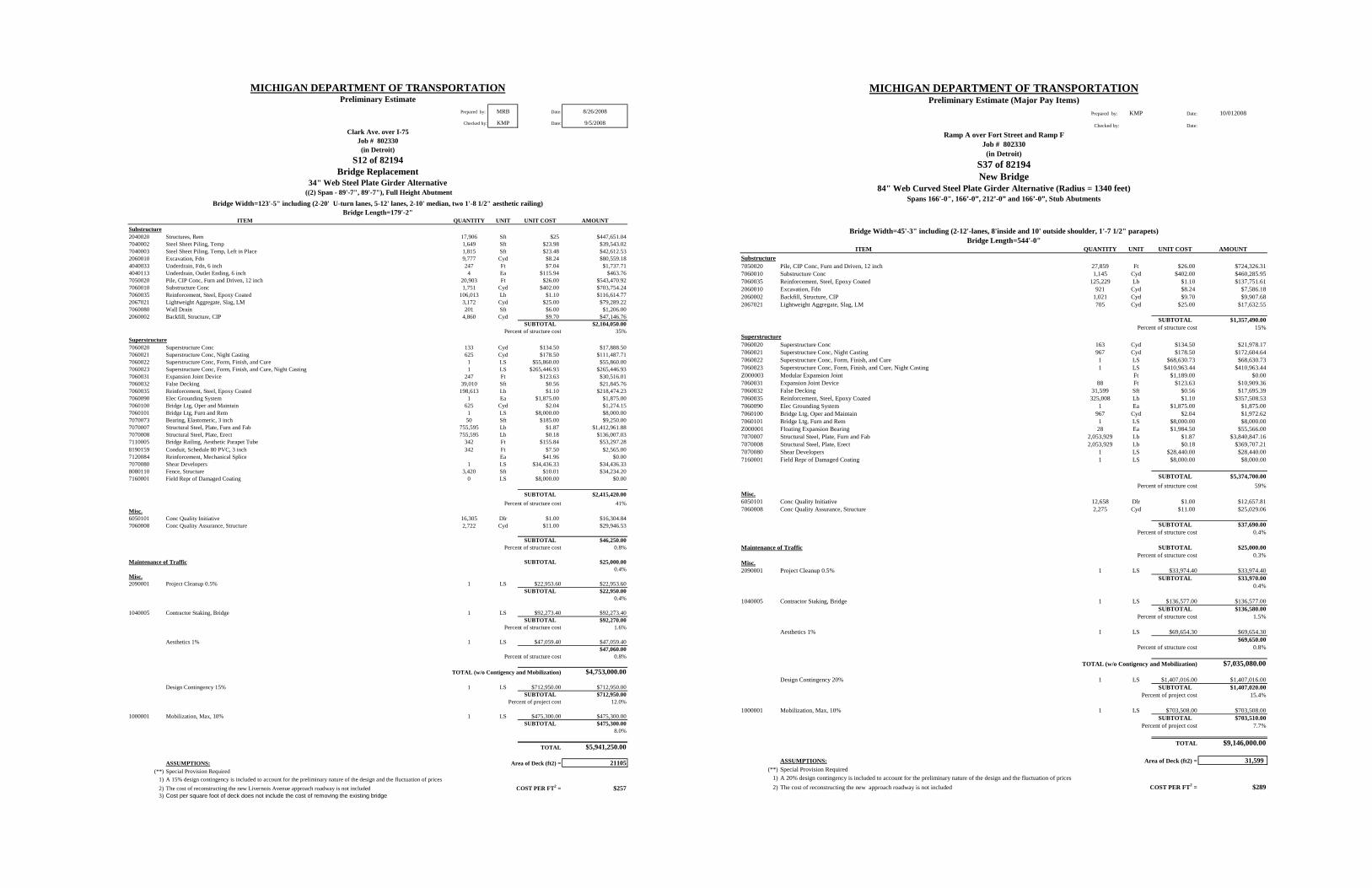
MICHIGAN DEPARTMENT OF TRANSPORTATIONPreliminary Estimate
Prepared by: MRB Date: 8/26/2008
Checked by: KMP Date: 9/5/2008Clark Ave. over I-75
Job # 802330(in Detroit)
S12 of 82194Bridge Replacement
34" Web Steel Plate Girder Alternative ((2) Span - 89'-7", 89'-7"), Full Height Abutment
Bridge Length=179'-2"ITEM QUANTITY UNIT UNIT COST AMOUNT
Substructure2040020 Structures, Rem 17,906 Sft $25 $447,651.047040002 Steel Sheet Piling, Temp 1,649 Sft $23.98 $39,543.027040003 Steel Sheet Piling, Temp, Left in Place 1,815 Sft $23.48 $42,612.532060010 Excavation, Fdn 9,777 Cyd $8.24 $80,559.184040033 Underdrain, Fdn, 6 inch 247 Ft $7.04 $1,737.714040113 Underdrain, Outlet Ending, 6 inch 4 Ea $115.94 $463.767050020 Pile, CIP Conc, Furn and Driven, 12 inch 20,903 Ft $26.00 $543,470.927060010 Substructure Conc 1,751 Cyd $402.00 $703,754.247060035 Reinforcement, Steel, Epoxy Coated 106,013 Lb $1.10 $116,614.772067021 Lightweight Aggregate, Slag, LM 3,172 Cyd $25.00 $79,289.227060080 Wall Drain 201 Sft $6.00 $1,206.002060002 Backfill, Structure, CIP 4,860 Cyd $9.70 $47,146.76
SUBTOTAL $2,104,050.00Percent of structure cost 35%
Superstructure7060020 Superstructure Conc 133 Cyd $134.50 $17,888.507060021 Superstructure Conc, Night Casting 625 Cyd $178.50 $111,487.717060022 Superstructure Conc, Form, Finish, and Cure 1 LS $55,860.00 $55,860.007060023 Superstructure Conc, Form, Finish, and Cure, Night Casting 1 LS $265,446.93 $265,446.937060031 Expansion Joint Device 247 Ft $123.63 $30,516.017060032 False Decking 39,010 Sft $0.56 $21,845.767060035 Reinforcement, Steel, Epoxy Coated 198,613 Lb $1.10 $218,474.237060090 Elec Grounding System 1 Ea $1,875.00 $1,875.007060100 Bridge Ltg, Oper and Maintain 625 Cyd $2.04 $1,274.157060101 Bridge Ltg, Furn and Rem 1 LS $8,000.00 $8,000.007070073 Bearing, Elastomeric, 3 inch 50 Sft $185.00 $9,250.007070007 Structural Steel, Plate, Furn and Fab 755,595 Lb $1.87 $1,412,961.887070008 Structural Steel, Plate, Erect 755,595 Lb $0.18 $136,007.037110005 Bridge Railing, Aesthetic Parapet Tube 342 Ft $155.84 $53,297.288190159 Conduit, Schedule 80 PVC, 3 inch 342 Ft $7.50 $2,565.007120084 Reinforcement, Mechanical Splice Ea $41.96 $0.007070080 Shear Developers 1 LS $34,436.33 $34,436.338080110 Fence, Structure 3,420 Sft $10.01 $34,234.207160001 Field Repr of Damaged Coating 0 LS $8,000.00 $0.00
SUBTOTAL $2,415,420.00Percent of structure cost 41%
Misc.6050101 Conc Quality Initiative 16,305 Dlr $1.00 $16,304.847060008 Conc Quality Assurance, Structure 2,722 Cyd $11.00 $29,946.53
SUBTOTAL $46,250.00Percent of structure cost 0.8%
Maintenance of Traffic SUBTOTAL $25,000.000.4%
Misc.2090001 Project Cleanup 0.5% 1 LS $22,953.60 $22,953.60
SUBTOTAL $22,950.000.4%
1040005 Contractor Staking, Bridge 1 LS $92,273.40 $92,273.40SUBTOTAL $92,270.00
Percent of structure cost 1.6%
Aesthetics 1% 1 LS $47,059.40 $47,059.40$47,060.00
Percent of structure cost 0.8%
TOTAL (w/o Contigency and Mobilization) $4,753,000.00
Design Contingency 15% 1 LS $712,950.00 $712,950.00SUBTOTAL $712,950.00
Percent of project cost 12.0%
1000001 Mobilization, Max, 10% 1 LS $475,300.00 $475,300.00SUBTOTAL $475,300.00
8.0%
TOTAL $5,941,250.00
ASSUMPTIONS: Area of Deck (ft2) = 21105(**) Special Provision Required
1) A 15% design contingency is included to account for the preliminary nature of the design and the fluctuation of prices2) The cost of reconstructing the new Livernois Avenue approach roadway is not included COST PER FT2 = $2573) Cost per square foot of deck does not include the cost of removing the existing bridge
Bridge Width=123'-5" including (2-20' U-turn lanes, 5-12' lanes, 2-10' median, two 1'-8 1/2" aesthetic railing)
MICHIGAN DEPARTMENT OF TRANSPORTATIONPreliminary Estimate (Major Pay Items)
Prepared by: KMP Date: 10/012008
Checked by: Date:
Ramp A over Fort Street and Ramp FJob # 802330
(in Detroit)S37 of 82194New Bridge
84" Web Curved Steel Plate Girder Alternative (Radius = 1340 feet)Spans 166'-0", 166’-0”, 212’-0” and 166’-0”, Stub Abutments
Bridge Length=544'-0"ITEM QUANTITY UNIT UNIT COST AMOUNT
Substructure7050020 Pile, CIP Conc, Furn and Driven, 12 inch 27,859 Ft $26.00 $724,326.317060010 Substructure Conc 1,145 Cyd $402.00 $460,285.957060035 Reinforcement, Steel, Epoxy Coated 125,229 Lb $1.10 $137,751.612060010 Excavation, Fdn 921 Cyd $8.24 $7,586.182060002 Backfill, Structure, CIP 1,021 Cyd $9.70 $9,907.682067021 Lightweight Aggregate, Slag, LM 705 Cyd $25.00 $17,632.55
SUBTOTAL $1,357,490.00Percent of structure cost 15%
Superstructure7060020 Superstructure Conc 163 Cyd $134.50 $21,978.177060021 Superstructure Conc, Night Casting 967 Cyd $178.50 $172,604.647060022 Superstructure Conc, Form, Finish, and Cure 1 LS $68,630.73 $68,630.737060023 Superstructure Conc, Form, Finish, and Cure, Night Casting 1 LS $410,963.44 $410,963.44Z000003 Modular Expansion Joint Ft $1,189.00 $0.007060031 Expansion Joint Device 88 Ft $123.63 $10,909.367060032 False Decking 31,599 Sft $0.56 $17,695.397060035 Reinforcement, Steel, Epoxy Coated 325,008 Lb $1.10 $357,508.537060090 Elec Grounding System 1 Ea $1,875.00 $1,875.007060100 Bridge Ltg, Oper and Maintain 967 Cyd $2.04 $1,972.627060101 Bridge Ltg, Furn and Rem 1 LS $8,000.00 $8,000.00Z000001 Floating Expansion Bearing 28 Ea $1,984.50 $55,566.007070007 Structural Steel, Plate, Furn and Fab 2,053,929 Lb $1.87 $3,840,847.167070008 Structural Steel, Plate, Erect 2,053,929 Lb $0.18 $369,707.217070080 Shear Developers 1 LS $28,440.00 $28,440.007160001 Field Repr of Damaged Coating 1 LS $8,000.00 $8,000.00
SUBTOTAL $5,374,700.00Percent of structure cost 59%
Misc.6050101 Conc Quality Initiative 12,658 Dlr $1.00 $12,657.817060008 Conc Quality Assurance, Structure 2,275 Cyd $11.00 $25,029.06
SUBTOTAL $37,690.00Percent of structure cost 0.4%
Maintenance of Traffic SUBTOTAL $25,000.00Percent of structure cost 0.3%
Misc.2090001 Project Cleanup 0.5% 1 LS $33,974.40 $33,974.40
SUBTOTAL $33,970.000.4%
1040005 Contractor Staking, Bridge 1 LS $136,577.00 $136,577.00SUBTOTAL $136,580.00
Percent of structure cost 1.5%
Aesthetics 1% 1 LS $69,654.30 $69,654.30$69,650.00
Percent of structure cost 0.8%
TOTAL (w/o Contigency and Mobilization) $7,035,080.00
Design Contingency 20% 1 LS $1,407,016.00 $1,407,016.00SUBTOTAL $1,407,020.00
Percent of project cost 15.4%
1000001 Mobilization, Max, 10% 1 LS $703,508.00 $703,508.00SUBTOTAL $703,510.00
Percent of project cost 7.7%
TOTAL $9,146,000.00
ASSUMPTIONS: Area of Deck (ft2) = 31,599 (**) Special Provision Required
1) A 20% design contingency is included to account for the preliminary nature of the design and the fluctuation of prices2) The cost of reconstructing the new approach roadway is not included COST PER FT2 = $289
Bridge Width=45'-3" including (2-12'-lanes, 8'inside and 10' outside shoulder, 1'-7 1/2" parapets)

MICHIGAN DEPARTMENT OF TRANSPORTATIONPreliminary Estimate (Major Pay Items)
Prepared by: KMP Date: 10//12008
Checked by: Date:
Ramp B over NB Service Drive, Livernois and Fort StreetJob # 802330
(in Detroit)S38 of 82194New Bridge
Unit 1 - 54" Web Curved Steel Plate Girder Alternative (Radius = 1500 feet)Spans 127'-6", 158’-9”, 150’-3” and 110’-0” with Stub Abutment
Unit 2 - 84" Web Curved Steel Plate Girder Alternative (Radius = 1500 feet)Spans 251'-6" and 151’-6” with Stub Abutment
Bridge Length=949'-6"ITEM QUANTITY UNIT UNIT COST AMOUNT
Substructure7050020 Pile, CIP Conc, Furn and Driven, 12 inch 27,620 Ft $26.00 $718,131.777060010 Substructure Conc 1,447 Cyd $402.00 $581,721.877060035 Reinforcement, Steel, Epoxy Coated 156,594 Lb $1.10 $172,253.35Z000004 Fill, Lightweight, EPS Block 983 Cyd $77.00 $75,691.342060010 Excavation, Fdn 921 Cyd $8.24 $7,586.182060002 Backfill, Structure, CIP 4,302 Cyd $9.70 $41,730.322067021 Lightweight Aggregate, Slag, LM 472 Cyd $25.00 $11,810.09
SUBTOTAL $1,608,920.00Percent of structure cost 12%
Superstructure7060020 Superstructure Conc 224 Cyd $134.50 $30,102.907060021 Superstructure Conc, Night Casting 1,313 Cyd $178.50 $234,284.027060022 Superstructure Conc, Form, Finish, and Cure 1 LS $94,001.63 $94,001.637060023 Superstructure Conc, Form, Finish, and Cure, Night Casting 1 LS $557,819.09 $557,819.09Z000003 Modular Expansion Joint 132 Ft $1,189.00 $157,379.617060031 Expansion Joint Device Ft $123.63 $0.007060032 False Decking 43,280 Sft $0.56 $24,236.897060035 Reinforcement, Steel, Epoxy Coated 441,578 Lb $1.10 $485,735.837060090 Elec Grounding System 1 Ea $1,875.00 $1,875.007060100 Bridge Ltg, Oper and Maintain 1,313 Cyd $2.04 $2,677.537060101 Bridge Ltg, Furn and Rem 1 LS $8,000.00 $8,000.00Z000001 Floating Expansion Bearing 56 Ea $1,984.50 $111,132.007070007 Structural Steel, Plate, Furn and Fab 3,183,276 Lb $1.87 $5,952,725.797070008 Structural Steel, Plate, Erect 3,183,276 Lb $0.18 $572,989.657070080 Shear Developers 1 LS $38,952.00 $38,952.007160001 Field Repr of Damaged Coating 1 LS $8,000.00 $8,000.00
SUBTOTAL $8,279,910.00Percent of structure cost 62%
Misc.6050101 Conc Quality Initiative 16,320 Dlr $1.00 $16,320.127060008 Conc Quality Assurance, Structure 2,983 Cyd $11.00 $32,817.38
SUBTOTAL $49,140.00Percent of structure cost 0.4%
Maintenance of Traffic SUBTOTAL $25,000.00Percent of structure cost 0.2%
Misc.2090001 Project Cleanup 0.5% 1 LS $49,814.85 $49,814.85
SUBTOTAL $49,810.000.4%
1040005 Contractor Staking, Bridge 1 LS $200,255.60 $200,255.60SUBTOTAL $200,260.00
Percent of structure cost 1.5%
Aesthetics 1% 1 LS $102,130.40 $102,130.40$102,130.00
Percent of structure cost 0.8%
TOTAL (w/o Contigency and Mobilization) $10,315,170.00
Design Contingency 20% 1 LS $2,063,034.00 $2,063,034.00SUBTOTAL $2,063,030.00
Percent of project cost 15.4%
1000001 Mobilization, Max, 10% 1 LS $1,031,517.00 $1,031,517.00SUBTOTAL $1,031,520.00
Percent of project cost 7.7%
TOTAL $13,410,000.00
ASSUMPTIONS: Area of Deck (ft2) = 43,280 (**) Special Provision Required
1) A 20% design contingency is included to account for the preliminary nature of the design and the fluctuation of prices2) The cost of reconstructing the new approach roadway is not included COST PER FT2 = $310
Bridge Width=45'-3" including (2-12'-lanes, 8'inside and 10' outside shoulder, 1'-7 1/2" parapets)
MICHIGAN DEPARTMENT OF TRANSPORTATIONPreliminary Estimate (Major Pay Items)
Prepared by: KMP Date: 9/26/2008
Checked by: Date:
Ramp C over I-75Job # 802330
(in Detroit)S39 of 82194 and S40 of 82194
New BridgesS39 of 82194 - 84" Web Curved Steel Plate Girder Alternative (Radius = 1641 feet)Spans 153’-0”, 257’-8”, 192’-6”, 159’-6”, 198’-6” and 142'-0", High Wall and Pile Bent AbutmentsS40 of 82194 - 54" Web Curved Steel Plate Girder Alternative (Radius = 818 feet)
Spans 86’-8”and 114’-8”, High Wall Abutments, Straddle Bent
Bridge Length=1103'-2" (Structure 1), 201'-4" (Structure 2)ITEM QUANTITY UNIT UNIT COST AMOUNT
Substructure7050020 Pile, CIP Conc, Furn and Driven, 12 inch 65,621 Ft $26.00 $1,706,139.557060010 Substructure Conc 3,385 Cyd $402.00 $1,360,589.487060035 Reinforcement, Steel, Epoxy Coated 430,278 Lb $1.10 $473,305.562067021 Lightweight Aggregate, Slag, LM 3,337 Cyd $25.00 $83,436.93Z000004 Fill, Lightweight, EPS Block 3,337 Cyd $77.00 $256,985.742060010 Excavation, Fdn 436 Cyd $8.24 $3,590.502060002 Backfill, Structure, CIP 3,426 Cyd $9.70 $33,235.40
SUBTOTAL $3,917,280.00Percent of structure cost 17%
Superstructure7060020 Superstructure Conc 367 Cyd $134.50 $49,320.787060021 Superstructure Conc, Night Casting 2,151 Cyd $178.50 $383,934.937060022 Superstructure Conc, Form, Finish, and Cure 1 LS $154,012.84 $154,012.847060023 Superstructure Conc, Form, Finish, and Cure, Night Casting 1 LS $914,130.78 $914,130.78Z000003 Modular Expansion Joint 88 Ft $1,189.00 $104,919.747060031 Expansion Joint Device 112 Ft $123.63 $13,876.487060032 False Decking 70,926 Sft $0.56 $39,718.297060035 Reinforcement, Steel, Epoxy Coated 723,623 Lb $1.10 $795,985.187060090 Elec Grounding System 1 Ea $1,875.00 $1,875.007060100 Bridge Ltg, Oper and Maintain 2,151 Cyd $2.04 $4,387.837060101 Bridge Ltg, Furn and Rem 1 LS $8,000.00 $8,000.00Z000001 Floating Expansion Bearing 56 Ea $1,984.50 $111,132.007070007 Structural Steel, Plate, Furn and Fab 4,875,231 Lb $1.87 $9,116,682.137070008 Structural Steel, Plate, Erect 4,875,231 Lb $0.18 $877,541.607070080 Shear Developers 1 LS $63,832.00 $63,832.007160001 Field Repr of Damaged Coating 1 LS $8,000.00 $8,000.00
SUBTOTAL $12,647,350.00Percent of structure cost 56%
Misc.6050101 Conc Quality Initiative 34,890 Dlr $1.00 $34,890.497060008 Conc Quality Assurance, Structure 5,902 Cyd $11.00 $64,923.59
SUBTOTAL $99,810.00Percent of structure cost 0.4%
Maintenance of Traffic SUBTOTAL $25,000.00Percent of structure cost 0.1%
Misc.2090001 Project Cleanup 0.5% 1 LS $83,447.20 $83,447.20
SUBTOTAL $83,450.000.4%
1040005 Contractor Staking, Bridge 1 LS $335,457.80 $335,457.80SUBTOTAL $335,460.00
Percent of structure cost 1.5%
Aesthetics 1% 1 LS $171,083.50 $171,083.50$171,080.00
Percent of structure cost 0.8%
TOTAL (w/o Contigency and Mobilization) $17,279,430.00
Design Contingency 20% 1 LS $3,455,886.00 $3,455,886.00SUBTOTAL $3,455,890.00
Percent of project cost 15.4%
1000001 Mobilization, Max, 10% 1 LS $1,727,943.00 $1,727,943.00SUBTOTAL $1,727,940.00
Percent of project cost 7.7%
TOTAL $22,463,000.00
ASSUMPTIONS: Area of Deck (ft2) = 70925(**) Special Provision Required
1) A 20% design contingency is included to account for the preliminary nature of the design and the fluctuation of prices2) The cost of reconstructing the new approach roadway is not included COST PER FT2 = $317
Bridge Width=45'-3" including (2-12'-lanes, 8'inside and 10' outside shoulder, 1'-7 1/2" parapets)

MICHIGAN DEPARTMENT OF TRANSPORTATIONPreliminary Estimate (Major Pay Items)
Prepared by: KMP Date: 9/24/2008
Checked by: Date:
Ramp D over I-75Job # 802330
(in Detroit)S41 of 82194New Bridge
114" and 84" Web Curved Steel Plate Girder Alternative (Radius = 1574 feet)Unit 1 Spans 181’-2”, 170’-10”, 170’-10”, 170’-10” and 149’-10”, Unit 2 Spans 241’-6”, 357’-6” and 241’-6”. Pile Bent Abutment
Bridge Length=1684'-0"ITEM QUANTITY UNIT UNIT COST AMOUNT
Substructure7050020 Pile, CIP Conc, Furn and Driven, 12 inch 53,548 Ft $26.00 $1,392,259.597060010 Substructure Conc 2,724 Cyd $402.00 $1,095,106.797060035 Reinforcement, Steel, Epoxy Coated 382,508 Lb $1.10 $420,758.992067021 Lightweight Aggregate, Slag, LM 816 Cyd $25.00 $20,404.402060010 Excavation, Fdn 461 Cyd $8.24 $3,797.652060002 Backfill, Structure, CIP 1,125 Cyd $9.70 $10,911.35
SUBTOTAL $2,943,240.00Percent of structure cost 13%
Superstructure7060020 Superstructure Conc 366 Cyd $134.50 $49,192.467060021 Superstructure Conc, Night Casting 2,295 Cyd $178.50 $409,585.547060022 Superstructure Conc, Form, Finish, and Cure 1 LS $153,612.13 $153,612.137060023 Superstructure Conc, Form, Finish, and Cure, Night Casting 1 LS $975,203.67 $975,203.67Z000003 Modular Expansion Joint 132 Ft $1,189.00 $157,379.617060032 False Decking 75,670 Sft $0.56 $42,375.047060035 Reinforcement, Steel, Epoxy Coated 664,585 Lb $1.10 $731,043.507060090 Elec Grounding System 1 Ea $1,875.00 $1,875.007060100 Bridge Ltg, Oper and Maintain 2,295 Cyd $2.04 $4,680.987060101 Bridge Ltg, Furn and Rem 1 LS $8,000.00 $8,000.00Z000001 Floating Expansion Bearing 56 Ea $1,984.50 $111,132.007070007 Structural Steel, Plate, Furn and Fab 6,824,765 Lb $1.50 $10,237,147.507070008 Structural Steel, Plate, Erect 6,824,765 Lb $0.18 $1,228,457.707070080 Shear Developers 1 LS $34,160.00 $34,160.007160001 Field Repr of Damaged Coating 1 LS $8,000.00 $8,000.00
SUBTOTAL $14,151,850.00Percent of structure cost 61%
Misc.6050101 Conc Quality Initiative 30,094 Dlr $1.00 $30,093.857060008 Conc Quality Assurance, Structure 5,384 Cyd $11.00 $59,229.35
SUBTOTAL $89,320.00Percent of structure cost 0.4%
Maintenance of Traffic SUBTOTAL $25,000.00Percent of structure cost 0.1%
Misc.2090001 Project Cleanup 0.5% 1 LS $86,047.05 $86,047.05
SUBTOTAL $86,050.000.4%
1040005 Contractor Staking, Bridge 2% 1 LS $345,909.20 $345,909.20SUBTOTAL $345,910.00
Percent of structure cost 1.5%
Aesthetics 1% 1 LS $176,413.70 $176,413.70$176,410.00
Percent of structure cost 0.8%
TOTAL (w/o Contigency and Mobilization) $17,817,780.00
Design Contingency 20% 1 LS $3,563,556.00 $3,563,556.00SUBTOTAL $3,563,560.00
Percent of project cost 15.4%
1000001 Mobilization, Max, 10% 1 LS $1,781,778.00 $1,781,778.00SUBTOTAL $1,781,780.00
Percent of project cost 7.7%
TOTAL $23,163,000.00
ASSUMPTIONS: Area of Deck (ft2) = 75670(**) Special Provision Required
1) A 20% design contingency is included to account for the preliminary nature of the design and the fluctuation of prices2) The cost of reconstructing the new approach roadway is not included COST PER FT2 = $306
Bridge Width=45'-3" including (2-12'-lanes, 8'inside and 10' outside shoulder, 1'-7 1/2" parapets)
MICHIGAN DEPARTMENT OF TRANSPORTATIONPreliminary Estimate
Prepared by: AJK Date: 10/30/2008
Checked by: KMP Date: 11/11/2008Ramp E over Ramp F
Job # 802330(in Detroit)
S42 of 82194
6 - 42" Spread PPC Box Beam AlternativeSingle Span - (112'-0"), Full Height Abutment
ITEM QUANTITY UNIT UNIT COST AMOUNTSubstructure7050020 Pile, CIP Conc, Furn and Driven, 12 inch 8,209 Ft $26.00 $213,444.427060010 Substructure Conc 985 Cyd $402.00 $395,951.397060035 Reinforcement, Steel, Epoxy Coated 49,248 Lb $1.10 $54,172.452067021 Lightweight Aggregate, Slag, LM 2,148 Cyd $25.00 $53,707.002060010 Excavation, Fdn 3,088 Cyd $8.24 $25,445.722060002 Backfill, Structure, CIP 496 Cyd $9.70 $4,809.48
SUBTOTAL $747,530.00Percent of structure cost 54%
Superstructure7060020 Superstructure Conc 27 Cyd $134.50 $3,603.667060021 Superstructure Conc, Night Casting 139 Cyd $178.50 $24,885.487060022 Superstructure Conc, Form, Finish, and Cure 1 LS $11,253.06 $11,253.067060023 Superstructure Conc, Form, Finish, and Cure, Night Casting 1 LS $59,251.14 $59,251.147060031 Expansion Joint Device 40 Ft $123.63 $4,945.207060035 Reinforcement, Steel, Epoxy Coated 39,149 Lb $1.10 $43,064.447060090 Elec Grounding System 1 Ea $1,875.00 $1,875.007060100 Bridge Ltg, Oper and Maintain 139 Cyd $2.04 $284.417060101 Bridge Ltg, Furn and Rem 1 LS $8,000.00 $8,000.007070073 Bearing, Elastomeric, 3 inch 23 Sft $185.00 $4,255.007080081 Prest Conc Box Beam, Furn, 42 inch 675 Ft $176.63 $119,225.257080082 Prest Conc Box Beam, Erect, 42 inch 675 Ft $12.00 $8,100.00
SUBTOTAL $288,740.00Percent of structure cost 21%
Maintenance of Traffic SUBTOTAL $0.00Percent of structure cost 0.0%
Misc.2090001 Project Cleanup 0.5% 1 LS $5,181.35 $5,181.35
SUBTOTAL $5,180.000.4%
1040005 Contractor Staking, Bridge 1 LS $20,829.00 $20,829.00SUBTOTAL $20,830.00
Percent of structure cost 1.5%
Aesthetics 1% 1 LS $10,622.80 $10,622.80$10,620.00
Percent of structure cost 0.8%
TOTAL (w/o Contigency and Mobilization) $1,072,900.00
Design Contingency 20% 1 LS $214,580.00 $214,580.00SUBTOTAL $214,580.00
Percent of project cost 15.4%
1000001 Mobilization, Max, 10% 1 LS $107,290.00 $107,290.00SUBTOTAL $107,290.00
Percent of project cost 7.7%
TOTAL $1,394,770.00
ASSUMPTIONS: Area of Deck (ft2) = 4313(**) Special Provision Required
1) A 20% design contingency is included to account for the preliminary nature of the design and the fluctuation of prices2) The cost of reconstructing the new Ramp E approach roadway is not included COST PER FT2 = $3233) Wing walls included in the Cost Estimate and the Square Foot Cost.
Bridge Width=37'-8" including (34'-0" of Roadway, two 1'-7 1/2" aesthetic railing, and 5" to accommodate tangent strucutre on curved alignemnt)

MICHIGAN DEPARTMENT OF TRANSPORTATIONPreliminary Estimate
Prepared by: MRB Date: 10/2/2008
Checked by: KMP Date: 11/12/2008Ramp E over Ramp F
Job # 802330(in Detroit)
Three-Sided Concrete Structure
ITEM QUANTITY UNIT UNIT COST AMOUNTSubstructure7050020 Pile, CIP Conc, Furn and Driven, 12 inch 8,103 Ft $26.00 $210,690.587060010 Substructure Conc 954 Cyd $402.00 $383,575.007060035 Reinforcement, Steel, Epoxy Coated 47,708 Lb $1.10 $52,479.17
SUBTOTAL $646,740.00Percent of structure cost 41%
SuperstructureThree-Sided Concrete Structure 126 LF $4,000.00 $504,000.00
SUBTOTAL $504,000.00Percent of structure cost 32%
Misc.6050101 Conc Quality Initiative 7,672 Dlr $1.00 $7,671.507060008 Conc Quality Assurance, Structure 954 Cyd $11.00 $10,495.83
SUBTOTAL $18,170.00Percent of structure cost 1.2%
Maintenance of Traffic SUBTOTAL $0.000.0%
Misc.2090001 Project Cleanup 0.5% 1 LS $5,844.55 $5,844.55
SUBTOTAL $5,840.000.4%
1040005 Contractor Staking, Bridge 1 LS $23,495.00 $23,495.00SUBTOTAL $23,500.00
Percent of structure cost 1.5%
Aesthetics 1 LS $11,982.50 $11,982.50$11,980.00
Percent of structure cost 0.8%
TOTAL (w/o Contigency and Mobilization) $1,210,230.00
Design Contingency 20% 1 LS $242,046.00 $242,046.00SUBTOTAL $242,050.00
Percent of project cost 15.4%
1000001 Mobilization, Max, 10% 1 LS $121,023.00 $121,023.00SUBTOTAL $121,020.00
Percent of project cost 7.7%
TOTAL $1,573,300.00
ASSUMPTIONS: Area of Deck (ft2) = 4313(**) Special Provision Required
1) A 20% design contingency is included to account for the preliminary nature of the design and the fluctuation of prices2) Area of Deck taken as Bridge Alternative. COST PER FT2 = $3653) Wing walls included in the Cost Estimate and the Square Foot Cost.4) Roadway not included in the cost.
Bridge Clear Width=42'-0"
MICHIGAN DEPARTMENT OF TRANSPORTATIONPreliminary Estimate (Major Pay Items)
Prepared by: KMP Date: 10/7/2008
Checked by: Date:
Ramps B & D over the Norfolk Southern RR and Plaza DriveJob # 802330
(in Detroit)R01-3 of 82194New Bridges
38" Web Steel Plate Girder AlternativeSpans 123'-6" Max. Span, Flared Girders High Wall Abutments
Bridge Length=117'-6" (+/-)ITEM QUANTITY UNIT UNIT COST AMOUNT
Substructure7050020 Pile, CIP Conc, Furn and Driven, 12 inch 32,122 Ft $26.00 $835,178.047060010 Substructure Conc 2,257 Cyd $402.00 $907,233.607060035 Reinforcement, Steel, Epoxy Coated 225,680 Lb $1.10 $248,248.00Z000004 Fill, Lightweight, EPS Block 6,495 Cyd $77.00 $500,115.912060010 Excavation, Fdn 1,265 Cyd $8.24 $10,424.362060002 Backfill, Structure, CIP 5,274 Cyd $9.70 $51,159.52
SUBTOTAL $2,552,360.00Percent of structure cost 48%
Superstructure7060020 Superstructure Conc 29 Cyd $134.50 $3,940.537060021 Superstructure Conc, Night Casting 354 Cyd $178.50 $63,115.257060022 Superstructure Conc, Form, Finish, and Cure 1 LS $12,305.00 $12,305.007060023 Superstructure Conc, Form, Finish, and Cure, Night Casting 1 LS $150,274.39 $150,274.39Z000003 Modular Expansion Joint Ft $1,189.00 $0.007060031 Expansion Joint Device 210 Ft $123.63 $25,987.037060032 False Decking 12,078 Sft $0.56 $6,763.687060035 Reinforcement, Steel, Epoxy Coated 112,211 Lb $1.10 $123,432.157060090 Elec Grounding System 1 Ea $1,875.00 $1,875.007060100 Bridge Ltg, Oper and Maintain 354 Cyd $2.04 $721.327060101 Bridge Ltg, Furn and Rem 1 LS $8,000.00 $8,000.007070073 Bearing, Elastomeric, 3 inch 26 Sft $185.00 $4,810.007070007 Structural Steel, Plate, Furn and Fab 514,386 Lb $1.87 $961,901.417070008 Structural Steel, Plate, Erect 514,386 Lb $0.18 $92,589.447070080 Shear Developers 1 LS $17,080.00 $17,080.007160001 Field Repr of Damaged Coating 1 LS $8,000.00 $8,000.00
SUBTOTAL $1,480,800.00Percent of structure cost 28%
Misc.6050101 Conc Quality Initiative 19,407 Dlr $1.00 $19,406.987060008 Conc Quality Assurance, Structure 2,640 Cyd $11.00 $29,036.53
SUBTOTAL $48,440.00Percent of structure cost 0.9%
Maintenance of Traffic SUBTOTAL $25,000.00Percent of structure cost 0.5%
Misc.2090001 Project Cleanup 0.5% 1 LS $20,533.00 $20,533.00
SUBTOTAL $20,530.000.4%
1040005 Contractor Staking, Bridge 1 LS $82,542.60 $82,542.60SUBTOTAL $82,540.00
Percent of structure cost 1.6%
Aesthetics 1% 1 LS $42,096.70 $42,096.70$42,100.00
Percent of structure cost 0.8%
TOTAL (w/o Contigency and Mobilization) $4,251,770.00
Design Contingency 15% 1 LS $637,765.50 $637,765.50SUBTOTAL $637,770.00
Percent of project cost 12.0%
1000001 Mobilization, Max, 10% 1 LS $425,177.00 $425,177.00SUBTOTAL $425,180.00
Percent of project cost 8.0%
TOTAL $5,315,000.00
ASSUMPTIONS: Area of Deck (ft2) = 12078(**) Special Provision Required
1) A 15% design contingency is included to account for the preliminary nature of the design and the fluctuation of prices2) The cost of reconstructing the new approach roadway is not included COST PER FT2 = $4403) Wing walls are included in the estimated cost and the cost per square foot.
Bridge Width varies 81'-2 1/4" to 125'-9 5/8" including (4-12'-lanes, 8' min. inside and 10' min. outside shoulder, 1'-6" parapets)

MICHIGAN DEPARTMENT OF TRANSPORTATIONPreliminary Estimate (Major Pay Items)
Prepared by: KMP Date: 10/14/2008
Checked by: Date:
Ramps A & C over the Norfolk Southern RR and Plaza DriveJob # 802330
(in Detroit)R01-4 of 82194New Bridges
38" Web Steel Plate Girder AlternativeSimple Span, Steel Girders, High Wall Abutments
Bridge Length=117'-6" (+/-)ITEM QUANTITY UNIT UNIT COST AMOUNT
Substructure7050020 Pile, CIP Conc, Furn and Driven, 12 inch 23,265 Ft $26.00 $604,880.627060010 Substructure Conc 1,751 Cyd $402.00 $703,861.807060035 Reinforcement, Steel, Epoxy Coated 175,090 Lb $1.10 $192,599.00Z000004 Fill, Lightweight, EPS Block 5,865 Cyd $77.00 $451,641.022060010 Excavation, Fdn 921 Cyd $8.24 $7,586.182060002 Backfill, Structure, CIP 4,302 Cyd $9.70 $41,730.32
SUBTOTAL $2,002,300.00Percent of structure cost 51%
Superstructure7060020 Superstructure Conc 28 Cyd $134.50 $3,728.927060021 Superstructure Conc, Night Casting 247 Cyd $178.50 $44,038.067060022 Superstructure Conc, Form, Finish, and Cure 1 LS $11,644.21 $11,644.217060023 Superstructure Conc, Form, Finish, and Cure, Night Casting 1 LS $104,852.52 $104,852.52Z000003 Modular Expansion Joint Ft $1,189.00 $0.007060031 Expansion Joint Device 141 Ft $123.63 $17,441.977060032 False Decking 8,462 Sft $0.56 $4,738.727060035 Reinforcement, Steel, Epoxy Coated 79,938 Lb $1.10 $87,931.307060090 Elec Grounding System 1 Ea $1,875.00 $1,875.007060100 Bridge Ltg, Oper and Maintain 247 Cyd $2.04 $503.297060101 Bridge Ltg, Furn and Rem 1 LS $8,000.00 $8,000.007070073 Bearing, Elastomeric, 3 inch 17 Sft $185.00 $3,145.007070007 Structural Steel, Plate, Furn and Fab 315,973 Lb $1.87 $590,870.397070008 Structural Steel, Plate, Erect 315,973 Lb $0.18 $56,875.227070080 Shear Developers 1 LS $10,980.00 $10,980.007160001 Field Repr of Damaged Coating 1 LS $8,000.00 $8,000.00
SUBTOTAL $954,620.00Percent of structure cost 24%
Misc.6050101 Conc Quality Initiative 14,958 Dlr $1.00 $14,958.007060008 Conc Quality Assurance, Structure 2,025 Cyd $11.00 $22,278.70
SUBTOTAL $37,240.00Percent of structure cost 1.0%
Maintenance of Traffic SUBTOTAL $25,000.00Percent of structure cost 0.6%
Misc.2090001 Project Cleanup 0.5% 1 LS $15,095.80 $15,095.80
SUBTOTAL $15,100.000.4%
1040005 Contractor Staking, Bridge 1 LS $60,685.20 $60,685.20SUBTOTAL $60,690.00
Percent of structure cost 1.6%
Aesthetics 1% 1 LS $30,949.50 $30,949.50$30,950.00
Percent of structure cost 0.8%
TOTAL (w/o Contigency and Mobilization) $3,125,900.00
Design Contingency 15% 1 LS $468,885.00 $468,885.00SUBTOTAL $468,890.00
Percent of project cost 12.0%
1000001 Mobilization, Max, 10% 1 LS $312,590.00 $312,590.00SUBTOTAL $312,590.00
Percent of project cost 8.0%
TOTAL $3,907,000.00
ASSUMPTIONS: Area of Deck (ft2) = 8462(**) Special Provision Required
1) A 15% design contingency is included to account for the preliminary nature of the design and the fluctuation of prices2) The cost of reconstructing the new approach roadway is not included COST PER FT2 = $4623) Wing walls are included in the estimated cost and the cost per square foot.
Bridge Width=71'-8" including (4-12'-lanes, 8' min. nside and 10' min. outside shoulder, 1'-7 1/2" parapets)
MICHIGAN DEPARTMENT OF TRANSPORTATIONPreliminary Estimate
Prepared by: MRB Date: 9/16/2008
Checked by: Date:
Solvay Ave. Pedestrian Bridge over I-75Job # 802330
(in Detroit)P01 of 82194
Pedestrian Bridge Replacement28" Steel Plate Girder
(2 Spans - 88'-0" & 101'-0" plus Ramps)
ITEM QUANTITY UNIT UNIT COST AMOUNTSubstructure2040020 Structures, Rem 3,848 Sft $25 $96,187.507060010 Substructure Conc 269 Cyd $402.00 $108,292.557060035 Reinforcement, Steel, Epoxy Coated 29,008 Lb $1.10 $31,908.38
SUBTOTAL $236,390.00Percent of structure cost 23%
Superstructure7060020 Superstructure Conc 258 Cyd $134.50 $34,669.877060022 Superstructure Conc, Form, Finish, and Cure 1 LS $108,262.78 $108,262.787060031 Expansion Joint Device 30 Ft $123.63 $3,708.907060032 False Decking 12,458 Sft $0.56 $6,976.207060035 Reinforcement, Steel, Epoxy Coated 95,428 Lb $1.10 $104,970.257070073 Bearing, Elastomeric, 3 inch 6 Sft $185.00 $1,110.007070007 Structural Steel, Plate, Furn and Fab 76,414 Lb $1.87 $142,895.087070008 Structural Steel, Plate, Erect 76,414 Lb $0.18 $13,754.617070080 Shear Developers 1 LS $2,304.00 $2,304.008080110 Fence, Structure 11,480 Sft $10.01 $114,914.80
SUBTOTAL $533,570.00Percent of structure cost 51%
Misc.6050101 Conc Quality Initiative 2,166 Dlr $1.00 $2,165.857060008 Conc Quality Assurance, Structure 527 Cyd $11.00 $5,798.68
SUBTOTAL $7,960.00Percent of structure cost 0.8%
Maintenance of Traffic SUBTOTAL $0.000.0%
Misc.2090001 Project Cleanup 0.5% 1 LS $3,889.60 $3,889.60
SUBTOTAL $3,890.000.4%
1040005 Contractor Staking, Bridge 1 LS $15,636.20 $15,636.20SUBTOTAL $15,640.00
Percent of structure cost 1.5%
Aesthetics 1 LS $7,974.50 $7,974.50$7,970.00
Percent of structure cost 0.8%
TOTAL (w/o Contingency and Mobilization) $805,420.00
Design Contingency 20% 1 LS $161,084.00 $161,084.00SUBTOTAL $161,080.00
Percent of project cost 15.4%
1000001 Mobilization, Max, 10% 1 LS $80,542.00 $80,542.00SUBTOTAL $80,540.00
Percent of project cost 7.7%
TOTAL $1,047,040.00
ASSUMPTIONS: Area of Deck (ft2) = 8610(**) Special Provision Required
1) A 20% design contingency is included to account for the preliminary nature of the design and the fluctuation of prices2) Cost per square foot of deck does not include the cost of removing the existing bridge COST PER FT2 = $108
Bridge Clear Width=14'-0"

MICHIGAN DEPARTMENT OF TRANSPORTATIONPreliminary Estimate
Prepared by: MRB Date: 9/16/2008
Checked by: Date:
Beard Ave. Pedestrian Bridge over I-75Job # 802330
(in Detroit)P02 of 82194
Pedestrian Bridge Replacement28" Plate Girder Steel Beam
(2 Spans - 89'-0" & 101'-0" plus Ramps)
ITEM QUANTITY UNIT UNIT COST AMOUNTSubstructure2040020 Structures, Rem 3,648 Sft $25 $91,200.007060010 Substructure Conc 309 Cyd $402.00 $124,336.757060035 Reinforcement, Steel, Epoxy Coated 33,797 Lb $1.10 $37,176.62
SUBTOTAL $252,710.00Percent of structure cost 22%
Superstructure7060020 Superstructure Conc 298 Cyd $134.50 $40,045.517060022 Superstructure Conc, Form, Finish, and Cure 1 LS $125,049.17 $125,049.177060031 Expansion Joint Device 30 Ft $123.63 $3,708.907060032 False Decking 13,593 Sft $0.56 $7,612.087060035 Reinforcement, Steel, Epoxy Coated 110,224 Lb $1.10 $121,246.137070073 Bearing, Elastomeric, 3 inch 6 Sft $185.00 $1,110.007070007 Structural Steel, Plate, Furn and Fab 76,414 Lb $1.87 $142,895.087070008 Structural Steel, Plate, Erect 76,414 Lb $0.18 $13,754.617070080 Shear Developers 1 LS $2,304.00 $2,304.008080110 Fence, Structure 13,260 Sft $10.01 $132,732.60
SUBTOTAL $590,460.00Percent of structure cost 51%
Misc.6050101 Conc Quality Initiative 2,487 Dlr $1.00 $2,486.737060008 Conc Quality Assurance, Structure 607 Cyd $11.00 $6,677.35
SUBTOTAL $9,160.00Percent of structure cost 0.8%
Maintenance of Traffic SUBTOTAL $0.000.0%
Misc.2090001 Project Cleanup 0.5% 1 LS $4,261.65 $4,261.65
SUBTOTAL $4,260.000.4%
1040005 Contractor Staking, Bridge 1 LS $17,131.80 $17,131.80SUBTOTAL $17,130.00
Percent of structure cost 1.5%
Aesthetics 1 LS $8,737.20 $8,737.20$8,740.00
Percent of structure cost 0.8%
TOTAL (w/o Contingency and Mobilization) $882,460.00
Design Contingency 20% 1 LS $176,492.00 $176,492.00SUBTOTAL $176,490.00
Percent of project cost 15.4%
1000001 Mobilization, Max, 10% 1 LS $88,246.00 $88,246.00SUBTOTAL $88,250.00
Percent of project cost 7.7%
TOTAL $1,147,200.00
ASSUMPTIONS: Area of Deck (ft2) = 9945(**) Special Provision Required
1) A 20% design contingency is included to account for the preliminary nature of the design and the fluctuation of prices2) Cost per square foot of deck does not include the cost of removing the existing bridge COST PER FT2 = $104
Bridge Clear Width=14'-0"
MICHIGAN DEPARTMENT OF TRANSPORTATIONPreliminary Estimate
Prepared by: MRB Date: 9/16/2008
Checked by: Date:
Waterman Ave. Pedestrian Bridge over I-75Job # 802330
(in Detroit)P10 of 82194
Pedestrian Bridge Replacement28" Steel Plate Girder
(2 Spans - 116'-0" & 112'-0" plus Ramps)
ITEM QUANTITY UNIT UNIT COST AMOUNTSubstructure2040020 Structures, Rem (included elsewhere) 0 Sft $25 $0.007060010 Substructure Conc 242 Cyd $402.00 $97,275.447060035 Reinforcement, Steel, Epoxy Coated 25,719 Lb $1.10 $28,290.82
SUBTOTAL $125,570.00Percent of structure cost 13%
Superstructure7060020 Superstructure Conc 242 Cyd $134.50 $32,604.537060022 Superstructure Conc, Form, Finish, and Cure 1 LS $101,813.40 $101,813.407060031 Expansion Joint Device 30 Ft $123.63 $3,708.907060032 False Decking 8,089 Sft $0.56 $4,529.707060035 Reinforcement, Steel, Epoxy Coated 89,650 Lb $1.10 $98,615.347070073 Bearing, Elastomeric, 3 inch 8 Sft $185.00 $1,480.007070007 Structural Steel, Plate, Furn and Fab 109,201 Lb $1.87 $204,205.577070008 Structural Steel, Plate, Erect 109,201 Lb $0.18 $19,656.157070080 Shear Developers 1 LS $2,760.00 $2,760.008080110 Fence, Structure 10,785 Sft $10.01 $107,957.85
SUBTOTAL $577,330.00Percent of structure cost 60%
Misc.6050101 Conc Quality Initiative 1,946 Dlr $1.00 $1,945.517060008 Conc Quality Assurance, Structure 484 Cyd $11.00 $5,328.31
SUBTOTAL $7,270.00Percent of structure cost 0.8%
Maintenance of Traffic SUBTOTAL $0.000.0%
Misc.2090001 Project Cleanup 0.5% 1 LS $3,550.85 $3,550.85
SUBTOTAL $3,550.000.4%
1040005 Contractor Staking, Bridge 1 LS $14,274.40 $14,274.40SUBTOTAL $14,270.00
Percent of structure cost 1.5%
Aesthetics 1 LS $7,279.90 $7,279.90$7,280.00
Percent of structure cost 0.8%
TOTAL (w/o Contingency and Mobilization) $735,270.00
Design Contingency 20% 1 LS $147,054.00 $147,054.00SUBTOTAL $147,050.00
Percent of project cost 15.4%
1000001 Mobilization, Max, 10% 1 LS $73,527.00 $73,527.00SUBTOTAL $73,530.00
Percent of project cost 7.7%
TOTAL $955,850.00
ASSUMPTIONS: Area of Deck (ft2) = 8089(**) Special Provision Required
1) A 20% design contingency is included to account for the preliminary nature of the design and the fluctuation of prices2) Cost of removing existing bridge is not included in this estimate COST PER FT2 = $118
Bridge Clear Width=14'-0"

MICHIGAN DEPARTMENT OF TRANSPORTATIONPreliminary Estimate
Prepared by: MRB Date: 9/16/2008
Checked by: Date:
Morrell Ave. Pedestrian Bridge over I-75Job # 802330
(in Detroit)P11 of 82194
Pedestrian Bridge Replacement30" Steel Plate Girder
(2 Spans - 100'-0" & 128'-0" plus Ramps)
ITEM QUANTITY UNIT UNIT COST AMOUNTSubstructure2040020 Structures, Rem 0 Sft $25 $0.007060010 Substructure Conc 122 Cyd $402.00 $48,875.517060035 Reinforcement, Steel, Epoxy Coated 12,516 Lb $1.10 $13,767.19
SUBTOTAL $62,640.00Percent of structure cost 11%
Superstructure7060020 Superstructure Conc 123 Cyd $134.50 $16,580.747060022 Superstructure Conc, Form, Finish, and Cure 1 LS $51,776.30 $51,776.307060031 Expansion Joint Device 18 Ft $123.63 $2,225.347060032 False Decking 4,005 Sft $0.56 $2,242.807060035 Reinforcement, Steel, Epoxy Coated 53,289 Lb $1.10 $58,617.637070073 Bearing, Elastomeric, 3 inch 5 Sft $185.00 $925.007070007 Structural Steel, Plate, Furn and Fab 73,756 Lb $1.87 $137,923.677070008 Structural Steel, Plate, Erect 73,756 Lb $0.18 $13,276.087070080 Shear Developers 1 LS $1,840.00 $1,840.008080110 Fence, Structure 8,900 Sft $10.01 $89,089.00
SUBTOTAL $374,500.00Percent of structure cost 63%
Misc.6050101 Conc Quality Initiative 978 Dlr $1.00 $977.517060008 Conc Quality Assurance, Structure 245 Cyd $11.00 $2,693.44
SUBTOTAL $3,670.00Percent of structure cost 0.6%
Maintenance of Traffic SUBTOTAL $0.000.0%
Misc.2090001 Project Cleanup 0.5% 1 LS $2,204.05 $2,204.05
SUBTOTAL $2,200.000.4%
1040005 Contractor Staking, Bridge 1 LS $8,860.20 $8,860.20SUBTOTAL $8,860.00
Percent of structure cost 1.5%
Aesthetics 1 LS $4,518.70 $4,518.70$4,520.00
Percent of structure cost 0.8%
TOTAL (w/o Contingency and Mobilization) $456,390.00
Design Contingency 20% 1 LS $91,278.00 $91,278.00SUBTOTAL $91,280.00
Percent of project cost 15.4%
1000001 Mobilization, Max, 10% 1 LS $45,639.00 $45,639.00SUBTOTAL $45,640.00
Percent of project cost 7.7%
TOTAL $593,310.00
ASSUMPTIONS: Area of Deck (ft2) = 4005(**) Special Provision Required
1) A 20% design contingency is included to account for the preliminary nature of the design and the fluctuation of pricesCOST PER FT2 = $148
Bridge Clear Width=8'-0"
MICHIGAN DEPARTMENT OF TRANSPORTATIONPreliminary Estimate
Prepared by: MRB Date: 9/16/2008
Checked by: Date:
McKinstry Ave. Pedestrian Bridge over I-75Job # 802330
(in Detroit)P12 of 82194
Pedestrian Bridge Replacement28" Steel Plate Girder
(2 Spans - 109'-0" & 100'-0" plus Ramps)
ITEM QUANTITY UNIT UNIT COST AMOUNTSubstructure2040020 Structures, Rem 0 Sft $25 $0.007060010 Substructure Conc 287 Cyd $402.00 $115,361.307060035 Reinforcement, Steel, Epoxy Coated 31,118 Lb $1.10 $34,229.46
SUBTOTAL $149,590.00Percent of structure cost 14%
Superstructure7060020 Superstructure Conc 291 Cyd $134.50 $39,199.907060022 Superstructure Conc, Form, Finish, and Cure 1 LS $122,408.61 $122,408.617060031 Expansion Joint Device 30 Ft $123.63 $3,708.907060032 False Decking 9,735 Sft $0.56 $5,451.607060035 Reinforcement, Steel, Epoxy Coated 107,896 Lb $1.10 $118,685.887070073 Bearing, Elastomeric, 3 inch 7 Sft $185.00 $1,295.007070007 Structural Steel, Plate, Furn and Fab 91,057 Lb $1.87 $170,277.177070008 Structural Steel, Plate, Erect 91,057 Lb $0.18 $16,390.327070080 Shear Developers 1 LS $2,544.00 $2,544.008080110 Fence, Structure 12,980 Sft $10.01 $129,929.80
SUBTOTAL $609,890.00Percent of structure cost 59%
Misc.6050101 Conc Quality Initiative 2,307 Dlr $1.00 $2,307.237060008 Conc Quality Assurance, Structure 578 Cyd $11.00 $6,362.59
SUBTOTAL $8,670.00Percent of structure cost 0.8%
Maintenance of Traffic SUBTOTAL $0.000.0%
Misc.2090001 Project Cleanup 0.5% 1 LS $3,840.75 $3,840.75
SUBTOTAL $3,840.000.4%
1040005 Contractor Staking, Bridge 1 LS $15,439.80 $15,439.80SUBTOTAL $15,440.00
Percent of structure cost 1.5%
Aesthetics 1 LS $7,874.30 $7,874.30$7,870.00
Percent of structure cost 0.8%
TOTAL (w/o Contingency and Mobilization) $795,300.00
Design Contingency 20% 1 LS $159,060.00 $159,060.00SUBTOTAL $159,060.00
Percent of project cost 15.4%
1000001 Mobilization, Max, 10% 1 LS $79,530.00 $79,530.00SUBTOTAL $79,530.00
Percent of project cost 7.7%
TOTAL $1,033,890.00
ASSUMPTIONS: Area of Deck (ft2) = 9735(**) Special Provision Required
1) A 20% design contingency is included to account for the preliminary nature of the design and the fluctuation of pricesCOST PER FT2 = $106
Bridge Clear Width=14'-0"

MICHIGAN DEPARTMENT OF TRANSPORTATION
Preliminary EstimateRetaining Walls
Job # 802330(in Detroit)
Retaining Wall Type cost
Cast-in-Place Cantilever Wall $ 45 /SFPrecast Cantilever Wall $ 35 /SFSteel Sheet Pile w/ Conc Face $ 29 /SFSoldier Pile & Lagging w/ Conc Face $ 65 /SF
MSE Wall:Furnish & Erect $ 30 /SFConcrete Level Pad $ 15 /LFCoping $ 175 /LFSelect Backfill $ 20 /CY
Backfill, Structure, CIP $ 7 /CYLightweight Aggregate, Slag, LM $ 24 /CYExacavation, fdn $ 8.5 /CYEPS Blocks $ 75 /CY
Contingency 30%
WALLLENGTH MIN WALL
HEIGHTMAX Wall HEIGHT
AVERAGE WALL
HEIGHTAREA CIP
CANTILEVERPRECAST
CANTILEVER MSE SHEET PILE W/ CONC FACE
SOLDIER PILE & LAG W/ CONC
FACE(ft) (ft) (ft) (ft) (ft2)
A 200 11.5 11.5 11.5 2300.0 $190,222 $160,322 $240,304 $86,710 $194,350B 80 10.5 10.5 10.5 840.0 $68,394 $57,474 $87,975 $31,668 $70,980C 345 10.0 16.5 11.5 3967.5 $319,519 $267,941 $393,879 N/A $335,254D 440 9.5 10.0 10.0 4400.0 $354,485 $297,285 $450,107 $165,880 $371,800E 1300 8.0 24.0 15.5 20150.0 $2,045,959 $1,784,009 $1,778,944 N/A N/AF 770 5.0 24.0 13.7 10549.0 $1,301,446 $1,164,309 $942,381 N/A N/AG 270 10.0 11.0 10.5 2835.0 $231,049 $194,194 $294,593 $106,880 $239,558H 1450 11.5 21.5 14.3 20735.0 $1,700,667 $1,431,112 $2,034,879 N/A N/AJ 260 12.0 16.0 14.0 3640.0 $293,981 $246,661 $350,059 N/A $307,580K 380 11.5 18.5 14.3 5434.0 $452,397 $381,755 $549,520 N/A N/AL 400 8.0 9.0 8.5 3400.0 $258,788 $214,588 $340,641 $128,180 $287,300M 715 7.0 20.0 13.5 9652.5 $714,755 $589,272 $829,699 N/A N/AN 880 7.0 24.0 15.0 13200.0 $1,070,702 $899,102 $1,203,093 N/A N/AP 2300 9.0 24.0 17.5 40250.0 $3,112,236 $2,588,986 $3,463,084 N/A N/AQ 275 10.0 16.0 12.0 3300.0 $269,639 $226,739 $329,416 N/A $278,850R 35 12.0 12.0 12.0 420.0 $38,661 $33,201 $48,829 $15,834 $35,490S 210 12.0 12.0 12.0 2520.0 $231,966 $199,206 $292,971 $95,004 $212,940T 1475 8.0 20.0 16.5 24337.5 $2,054,441 $1,738,054 $2,457,969 N/A N/AU 2200 5.5 22.0 16.0 35200.0 $2,636,010 $2,178,410 $3,000,517 N/A N/AV 380 5.0 14.0 8.8 3325.0 $267,323 $224,098 $340,721 N/A $280,963W 775 11.5 13.0 12.5 9687.5 $928,253 $802,315 $1,226,678 N/A $818,594X 270 16.0 22.0 19.5 5265.0 $358,053 $289,608 $415,025 N/A N/AY 360 18.0 26.0 23.3 8370.0 $663,171 $554,361 $664,181 N/A N/AZ 52 20.0 20.0 20.0 1040.0 $85,859 $72,339 $98,872 N/A N/A
AA 65 24.0 24.0 24.0 1560.0 $181,066 $160,786 $208,771 N/A N/ATOTAL 15887 236378
MICHIGAN DEPARTMENT OF TRANSPORTATION
Retaining WallsJob # 802330(in Detroit)
Summary of Options
WALL OPTIONS CONSTRUCTION COST WALL OPTIONS CONSTRUCTION
COSTA Option1: Steel Sheet Pile w/ Conc Face $86,710 N Option1: Precast Cantilever Wall $899,102
Option2: Precast Cantilever Wall $160,322 Option2: Cast-in-Place Cantilever Wall $1,070,702Option3: Cast-in-Place Cantilever Wall $190,222 Option3: MSE Wall $1,203,093Option4: Soldier Pile & Lagging w/ Conc Face $194,350 P Option1: Precast Cantilever Wall $2,588,986Option5: MSE Wall $240,304 Option2: Cast-in-Place Cantilever Wall $3,112,236
B Option1: Steel Sheet Pile w/ Conc Face $31,668 Option3: MSE Wall $3,463,084Option2: Precast Cantilever Wall $57,474 Q Option1: Precast Cantilever Wall $226,739Option3: Cast-in-Place Cantilever Wall $68,394 Option2: Cast-in-Place Cantilever Wall $269,639Option4: Soldier Pile & Lagging w/ Conc Face $70,980 Option3: Soldier Pile & Lagging w/ Conc Face $278,850Option5: MSE Wall $87,975 Option4: MSE Wall $329,416
C Option1: Precast Cantilever Wall $267,941 R Option1: Steel Sheet Pile w/ Conc Face $15,834Option2: Cast-in-Place Cantilever Wall $319,519 Option2: Precast Cantilever Wall $33,201Option3: Soldier Pile & Lagging w/ Conc Face $335,254 Option3: Cast-in-Place Cantilever Wall $38,661Option4: MSE Wall $393,879 Option4: Soldier Pile & Lagging w/ Conc Face $35,490
D Option1: Steel Sheet Pile w/ Conc Face $165,880 Option5: MSE Wall $48,829Option2: Precast Cantilever Wall $297,285 S Option1: Steel Sheet Pile w/ Conc Face $95,004Option3: Cast-in-Place Cantilever Wall $354,485 Option2: Precast Cantilever Wall $199,206Option4: Soldier Pile & Lagging w/ Conc Face $371,800 Option3: Cast-in-Place Cantilever Wall $231,966Option5: MSE Wall $450,107 Option4: Soldier Pile & Lagging w/ Conc Face $212,940
E Option1: Precast Cantilever Wall $1,784,009 Option5: MSE Wall $292,971Option2: Cast-in-Place Cantilever Wall $2,045,959 T Option1: Precast Cantilever Wall $1,738,054Option3: MSE Wall N/A* Option2: Cast-in-Place Cantilever Wall $2,054,441
F Option1: Precast Cantilever Wall $1,164,309 Option3: MSE Wall $2,457,969Option2: Cast-in-Place Cantilever Wall $1,301,446 U Option1: Precast Cantilever Wall $2,178,410Option3: MSE Wall N/A* Option2: Cast-in-Place Cantilever Wall $2,636,010
G Option1: Steel Sheet Pile w/ Conc Face $106,880 Option3: MSE Wall $3,000,517Option2: Precast Cantilever Wall $194,194 V Option1: Precast Cantilever Wall $224,098Option3: Cast-in-Place Cantilever Wall $231,049 Option2: Cast-in-Place Cantilever Wall $267,323Option4: Soldier Pile & Lagging w/ Conc Face $239,558 Option3: Soldier Pile & Lagging w/ Conc Face $280,963Option5: MSE Wall $294,593 Option4: MSE Wall $340,721
H Option1: Precast Cantilever Wall $1,431,112 W Option1: Precast Cantilever Wall $802,315Option2: Cast-in-Place Cantilever Wall $1,700,667 Option2: Cast-in-Place Cantilever Wall $928,253Option3: MSE Wall $2,034,879 Option3: Soldier Pile & Lagging w/ Conc Face $818,594
J Option1: Precast Cantilever Wall $246,661 Option4: MSE Wall $1,226,678Option2: Cast-in-Place Cantilever Wall $293,981 X Option1: Precast Cantilever Wall $289,608Option3: Soldier Pile & Lagging w/ Conc Face $307,580 Option2: Cast-in-Place Cantilever Wall $358,053Option4: MSE Wall $350,059 Option3: MSE Wall $415,025
K Option1: Precast Cantilever Wall $381,755 Y Option1: Precast Cantilever Wall $554,361Option2: Cast-in-Place Cantilever Wall $452,397 Option2: Cast-in-Place Cantilever Wall $663,171Option3: MSE Wall $549,520 Option3: MSE Wall $664,181
L Option1: Steel Sheet Pile w/ Conc Face $128,180 Z Option1: Precast Cantilever Wall $72,339Option2: Precast Cantilever Wall $214,588 Option2: Cast-in-Place Cantilever Wall $85,859Option3: Cast-in-Place Cantilever Wall $258,788 Option3: MSE Wall $98,872Option4: Soldier Pile & Lagging w/ Conc Face $287,300 AA Option1: Precast Cantilever Wall $160,786Option5: MSE Wall $340,641 Option2: MSE Wall $208,771
M Option1: Precast Cantilever Wall $589,272 Option3: Cast-in-Place Cantilever Wall $181,066Option2: Cast-in-Place Cantilever Wall $714,755Option3: MSE Wall $829,699
Note: preferred option in bold* MSE wall option is not applicable since EPS blocks should be used for this wall because of settlement issues

MICHIGAN DEPARTMENT OF TRANSPORTATIONPreliminary Estimate
Demolition Cost Estimate(for structures not being replaced)
Structure Area Unit Cost Cost(Sq.ft.)
Casgrain Street Pedestrain Bridge 3885.5 25$ 97,138$
Dragoon St. Bridge 16179.75 25$ 404,494$
Cavalry Street Pedestrain Bridge 5323.5 25$ 133,088$
Junction Street Bridge 10579 25$ 264,475$
Ferdinand Street Pedestrain Bridge 3638.5 25$ 90,963$
Waterman Street 21249 25$ 531,225$
Sub Total = 1,521,381$
20% Contingency = 304,276$
Total = 1,825,658$

Appendix C
Comparative Cost Estimate – Steel Girder vs. Tub Girder (Ramp D)

MICHIGAN DEPARTMENT OF TRANSPORTATIONComparative Cost Estimate Curved Steel Plate Girders vs. Curved Tub Girders
Prepared by: KMP Date: 9/20/2008
Checked by: Date:
Ramp D over I-75Job # 802330
(in Detroit)SXX of 82194New Bridge
Unit 2 Spans 241’-6”, 357’-6” and 241’-6”. Pile Bent Abutment
Unit Length=840'-6"
Curved Steel Plate Girder Alternative
Girder 1 558,920 lbsGirder 2 561,080 lbsGirder 3 563,640 lbsGirder 4 566,200 lbsGirder 5 658,930 lbsGirder 6 656,260 lbsGirder 7 666,640 lbsCross Frames 127,940 lbs
Total 4,359,610 lbs * $1.50/lb (fabricate) = 6,539,415$
Steel Curved Tub Girder Alternative
Tub Girder 1 1,493,800 lbsTub Girder 2 1,912,000 lbsCross Frames 274,690 lbsLongitudinal Bracing 132,980 lbsLongitudinal Flange Splice 128,800 lbs
Total 3,942,270 lbs * $2.10/lb (fabricate)* = 8,278,767$
* Units Costs are from Industrial Steel Corp. from a recent Michigan Bridge Project
Bridge Width=45'-3" including (2-12'-lanes, 8'inside and 10' outside shoulder, 1'-7 1/2" parapets)

Appendix D - Geotechnical Report (To come Nov. 30,2008)