engineering standard for fire water …hse.niordc.ir/uploads/86_26_e-sf-220.pdf · bases for a...
TRANSCRIPT
IPS-E-SF-220
This Standard is the property of Iranian Ministry of Petroleum. All rights are reserved to the owner. Neither whole nor any part of this document may be disclosed to any third party, reproduced, stored in any retrieval system or transmitted in any form or by any means without the prior written consent of the Iranian Ministry of Petroleum.
ENGINEERING STANDARD
FOR
FIRE WATER DISTRIBUTION
AND
STORAGE FACILITIES
ORIGINAL EDITION
NOV. 1993
This standard specification is reviewed and updated by the relevant technical committee on May 1998. The approved modifications are included in the present issue of IPS.

Nov. 1993
IPS-E-SF-220
1
CONTENTS : PAGE No.
0. INTRODUCTION ............................................................................................................................. 3 1. SCOPE ............................................................................................................................................ 4 2. REFERENCES ................................................................................................................................ 4 3. DEFINITIONS AND TERMINOLOGY ............................................................................................. 5 4. UNITS .............................................................................................................................................. 6 5. GENERAL ....................................................................................................................................... 6 6. WATER SUPPLIES......................................................................................................................... 6 7. BASES FOR A FIRE-FIGHTING WATER SYSTEM ...................................................................... 7
7.9 Fire-Water Ring Main System-General.................................................................................. 8 7.10 Fire-Water Ring Main/Network Design................................................................................ 8
8. FIRE-WATER PUMPING FACILITIES ......................................................................................... 10 9. PLANS .......................................................................................................................................... 11 10. GENERAL WINTERIZING .......................................................................................................... 11 11. WATER TANKS FOR FIRE PROTECTION ............................................................................... 12
11.1 Types of Tanks .................................................................................................................... 12 11.2 Capacity and Elevation....................................................................................................... 12 11.3 Location of Tanks ............................................................................................................... 13 11.4 Storage Facilities ................................................................................................................ 13 11.5 Steel Gravity and Suction Tanks ....................................................................................... 13 11.6 Pressure Tanks ................................................................................................................... 14 11.7 Housing ................................................................................................................................ 14 11.8 Buried Tanks ....................................................................................................................... 14 11.9 Low Pressure and High Pressure Storage Tanks............................................................ 15
12. FIRE HOSE REELS (WATER) FOR FIXED INSTALLATIONS ................................................. 15 12.1 Design .................................................................................................................................. 15 12.2 Reel Size .............................................................................................................................. 15 12.3 Range and Water Flow Rate............................................................................................... 16 12.4 General Considerations...................................................................................................... 16 12.5 Co-ordinating Spaces for Hose Reels............................................................................... 16 12.6 Water Supply for Hose Reels ............................................................................................. 17
13. WATER SPRAY FIXED SYSTEMS FOR FIRE PROTECTION ................................................. 19 13.1 Applicability......................................................................................................................... 19 13.2 Uses...................................................................................................................................... 19 13.3 Limitations ........................................................................................................................... 19 13.4 Alarms .................................................................................................................................. 19 13.5 Flushing Connections ........................................................................................................ 19 13.6 Water Supplies .................................................................................................................... 20 13.7 System Design and Installation......................................................................................... 20 13.8 Density and Application ..................................................................................................... 21 13.9 Fire and Explosion Prevention .......................................................................................... 26 13.10 Size of System................................................................................................................... 26 13.11 Separation of Fire Areas .................................................................................................. 26 13.12 Valves ................................................................................................................................. 27 13.13 Automatic Detection Equipment ..................................................................................... 27 13.14 Hydraulic Calculation ....................................................................................................... 27

Nov. 1993
IPS-E-SF-220
2
A APPENDIX A..................................................................................................................................... 28
PPENDICES
Nov. 1993
IPS-E-SF-220
3
0. INTRODUCTION
"Fire Fighting and Fire Protection Systems" are broad and contain variable subjects of paramount importance therefore, a group of engineering standards are prepared to cover the subject.
This group includes the following standards:
STANDARD CODE STANDARD TITLE
IPS-E-SF-120 "Off-Shore Fire Fighting Installations"
IPS-E-SF-140 "Foam Generating and Proportioning Systems"
IPS-E-SF-160 "CO2 Gas Fire Extinguishing Systems"
IPS-E-SF-180 "Dry Chemical Fire Extinguishing Systems"
IPS-E-SF-200 "Fire Fighting Sprinkler Systems"
IPS-E-SF-220 "Fire Water Distribution and Storage Facilities"
IPS-E-SF-240 "Fire Water Pump Systems"
IPS-E-SF-260 "Automatic Detectors and Fire Alarm Systems"
IPS-E-SF-280 "Telecommunication for Fire Fighting Operations"
IPS-E-SF-300 "Application of Breathing Apparatus in Safety and Fire Fighting"
IPS-E-SF-320 "Tugs, Fire-Fighting Off-Shore Vessels"
IPS-E-SF-340 "Fire Fighting Hose Box and/or Shelter"
This Standard covers:
FIRE WATER DISTRIBUTION
AND
STORAGE FACILITIES

Nov. 1993
IPS-E-SF-220
4
1. SCOPE
This Standard Specifies minimum requirements for water supply for fire-fighting purposes. It is important that all authorities concerned should work together to provide and maintain these minimum water supplies and discussions with municipality fire stations would include not only the water available from the hydrants but also help to assure the continuous and adequate flow of water for fire-fighting.
The following items are also included in this Standard:
a) Basic for a fire-fighting water system;
b) fire-water pumping facilities;
c) water tanks for fire protection;
d) fire hose reel (water) for fixed installation; and,
e) water spray fixed system.
Note:
This Standard is compiled on the bases of International Codes and practices. Requirements of passive defense are not included. Should this requirements be necessary in the design of new installations or existing facilities, decisions should be made by the NIOC executive board.
Note:
This standard specification is reviewed and updated by the relevant technical committee on May 1998. The approved modifications by T.C. were sent to IPS users as amendment No. 1 by circular No 76 on May 1998. These modifications are included in the present issue of IPS.
2. REFERENCES
Throughout this Standard the following dated and undated standards/codes are referred to. These referenced documents shall, to the extent specified herein, form a part of this standard. For dated references, the edition cited applies. The applicability of changes in dated references that occur after the cited date shall be mutually agreed upon by the Company and the Vendor. For undated references, the latest edition of the referenced documents (including any supplements and amendments) applies.
NIOC (NATIONAL IRANIAN OIL COMPANY)
EPM Section 15 "Outline Requirements for a Water Distribution System"
EPM Section 12 "For Major Installation"
PUSM Section 17 "Present Practice"
NIGC (NATIONAL IRANIAN GAS COMPANY)
703.3.7(a) "Water Supply and System"
703.10
NFC (NFPA) (NATIONAL FIRE CODES)
NFC Section 1231 "Water Supply"

Nov. 1993
IPS-E-SF-220
5
NFC Section 15 "Water Spray System"
NFC Section 22 "Water Tanks"
NFC Section 24 "Mains Water Supplies"
BSI (BRITISH STANDARDS INSTITUTION)
BS 5306 Part 1 "System Design Water Supply"
3. DEFINITIONS AND TERMINOLOGY
Coupling
A device for connecting lengths of hose so as to secure continuity from the source of a water supply to the delivery point.
Fire Hydrant (Underground Fire Hydrant)
An assembly contained in a pit or box below ground level and comprising a valve and outlet connection from a water supply main.
Fire Hydrant Pillar
A fire hydrant whose outlet connection is fitted to a vertical component projecting above ground level.
Foam Inlet
Fixed equipment consisting of an inlet connection, fixed piping and a discharge assembly, enabling firemen to introduce foam into an enclosed compartment.
Hose Reel
Fire-fighting equipment, consisting of a length of tubing fitted with a shut-off nozzle and attached to a reel, with a permanent connection to a pressurized water supply.
Hydrant Outlet
The component of fire hydrant to which the standpipe is connected.
Landing Valve
An assembly comprising a valve and outlet connection from a wet or dry riser.
Rising Main, Dry (Dry Riser)
A vertical pipe installed in a building for fire fighting purposes, fitted with inlet connections at fire brigade access level and landing valves at specified point, which is normally dry but is capable of being charged with water usually by pumping from fire service appliances.
Rising Main, Wet (Wet Riser)
A vertical pipe installed in a building for fire fighting purposes and permanently charged with water from a pressurized supply, and fitted with landing valves at specified points.
Nov. 1993
IPS-E-SF-220
6
Shut-off Nozzle
A device which is coupled to the outlet end of hose reel tubing and by means of which the jet of water or spray is controlled.
4. UNITS
International System of Units (SI) in accordance with IPS-E-GN-100 shall be used.
5. GENERAL
5.1 Water is the most commonly used agent for controlling and fighting a fire, by cooling adjacent equipment and for controlling and/or extinguishing the fire either by itself or combined as a foam. It can also provide protection for firefighters and other personnel in the event of fire. Water shall therefore be readily available at all the appropriate locations, at the correct pressure and in the required quantity.
5.2 Fire water should not be used for any other purpose.
5.3 Unless otherwise specified or agreed, the Company requirements are given for major installations such as refineries, petrochemical works, crude oil production areas where large facilities are provided, and for major storage areas.
5.4 In determining the quantity of fire water, i.e. "required fire water rate", protection of the following areas shall also be considered:
a) General process;
b) storage (low pressure), including pumpstations, manifolds and in line blenders, etc.;
c) pressure storage (LPG, etc.);
d) refrigerated storage (LNG etc.);
e) jetties;
f) loading.
5.5 Basically, the requirements consist of an independent fire grid main or ring main fed by permanently installed fire pumps taking suction from a suitable large capacity source of water such as storage tank, cooling tower basin, river, sea, etc. The actual source will depend on local conditions and is to be agreed with the Company.
The water will be used for direct application to fires and for the cooling of equipment. It will also be used for the production of foam.
6. WATER SUPPLIES
6.1 Nature of Supply
The choice of water supplies shall be made in cooperation with the relevant authorities.
6.2 Public Water Systems
(Applicable also to private supply systems.)
6.3 One or more connections from a reliable public water system of good pressure and adequate capacity furnishes a satisfactory supply. A high static water pressure shall not, however, be the criterion by which the efficiency of the supply is determined.
If this cannot be done, the post indicator valves shall be placed where they will be readily accessible

Nov. 1993
IPS-E-SF-220
7
in case of fire and not liable to injury. Where post indicator valves cannot readily be used, as in a city block, underground valves shall conform to these provisions and their locations and direction of turning to open shall be clearly marked.
6.4 Adequacy of water supply shall be determined by flow tests or other reliable means. Where flow tests are made, the flow in (L/min.) together with the static and residual pressures shall be indicated on the plan.
6.5 Public mains shall be of ample size, in no case smaller than 15 cm (6 in).
6.6 No pressure regulating valve shall be used in water supply except by special permission of the authority concerned. Where meters are used they shall be of an approved type.
6.7 Where connections are made from public waterworks systems, it may be necessary to guard against possible contamination of the public supply. The requirements of the public health authority shall be determined and followed.
6.8 Connections larger than 50.8 mm to public water systems shall be controlled by post indicator valves of a standard type and located not less than 12.2 m from the buildings and units protected.
7. BASES FOR A FIRE-FIGHTING WATER SYSTEM
7.1 A ring main system shall be laid around processing areas or parts thereof, utility areas, loading and filling facilities, tank farms and buildings whilst one single line shall be provided for jetties and a fire-fighting training ground, complete with block valves and hydrants.
7.2 The water supply shall be obtained from at least two centrifugal pumps of which one is electric motor-driven and one driven by a fully independent power source e.g. a diesel engine, the latter serving as a spare pump.
7.3 The water quantities required are based on the following considerations:
a) There will be only one major fire at a time.
b) In processing units the minimum water quantity is 200 dm3/s or air foam making and exposure protection. It is assumed that approximately 30% of this quantity is blown away and evaporates; the balance of this quantity, which is 140 dm3/s per processing unit, shall be drained via a drainage system.
1) The quantity of fire water required for a particular installation should be assessed in relation to fire incidents which could occur on that particular site, taking into account the fire hazard, the size, duties, and location of towers, vessels, etc. The fire water quantity for installations having a high potential fire hazard should normally be not less than 820 m3/h and no greater than 1360 m3/h.
c) For storage areas the quantity needed for making air foam for extinguishing the largest cone roof tank on fire and for exposure protection of adjacent tanks.
d) For pressure storage areas the quantity needed for exposure protection of spheres by means of sprinklers.
e) For jetties the quantity needed for fighting fires on jetty decks and ship manifolds with air foam as well as for exposure protection in these areas.
f) The policy for a single major fire or more to occur simultaneously shall be decided upon by the authorities concerned.
Note:
The above specification is based on one major fire only.
7.4 For new installations the quantities required for items (a) to (f) mentioned above shall be compared, and the largest figure shall be adhered to for the design of the fire-fighting system.

Nov. 1993
IPS-E-SF-220
8
The system pressure shall be such that at the most remote location a pressure of 10 bar can be maintained during a water take-off required at that location.
7.5 Fire-fighting water lines shall be provided with permanent hydrants.
Hydrants with 4 outlets shall be located around processing units, loading facilities, storage facilities for flammable liquids, and on jetty heads and berths.
Hydrants with two outlets shall be located around other areas, including jetty approaches.
7.6 Fire hose reels shall be located in each process unit, normally 31-47 m apart at certain strategic points.
7.7 The minimum fire water rate for various types of process units is given in Appendix A.
7.8 The water will be applied by means of hose and branch pipes using jet, spray or fog nozzles, or by fixed or portable monitors preferably with interchangeable nozzles for water or foam jets.
7.9 Fire-Water Ring Main System-General
7.9.1 Fire-water ring mains of the required capacity shall be laid to surround all processing units, storage facilities for flammable liquids, loading facilities for road vehicles and rail cars, bottle filling plants, warehouses, workshops, utilities, training centers, laboratories and offices. Normally, these units will also be bounded by service roads. Large areas shall be sub-divided into smaller sections, each enclosed by fire-water mains equipped with hydrants and block valves.
A single fire water pipeline is only acceptable for a fire-fighting training ground. Fire-water to jetties shall be supplied by a single pipeline provided that it is interconnected with a separate pipeline for water spray systems. The fire-water pipelines from the fire pumps to the jetty shall be provided with isolating valves, for closing in the event of serious damage to the jetty. These valves shall close without causing high surge pressures.
7.9.2 The fire-water mains shall be provided with full bore valved flushing connections so that all sections and dead ends can be properly flushed out. The flushing connections shall be sized for a fluid velocity in the relevant piping of not less than 80% of the velocity under normal design conditions but for not less than 2 m/s.
7.9.3 Fire-water mains shall normally be laid underground in order to provide a safe and secure system, and which will give in addition, protection against freezing for areas where the ambient temperature can drop below 0°C. When in exceptional circumstances, fire-water mains are installed above ground they shall be laid alongside roads and not in pipe tracks where they could be at risk from spill fires.
7.9.4 The basic requirements consist of an independent fire grid main or ring main fed by permanently installed fire pumps. The size of ring main and fire pumps shall be such as to provide a quantity of water sufficient for the largest single risk identified within the overall installation.
Suction will be from a suitable large capacity source of water such as storage tank, cooling tower basin, river, sea, etc. The actual source will depend on local conditions and is to be investigated. Pump suction lines shall be positioned in a safe and protected location and incorporate permanent, but easily cleanable strainers or screening equipment for the protection of fire pumps.
Advantage should be taken where available in obtaining additional emergency water supplies through a mutual aid scheme or by re-cycling but mandatory national or local authority requirements may modify these to a considerable extent.
7.10 Fire-Water Ring Main/Network Design
7.10.1 The fire-water mains network pipe sizes shall be calculated and based on design rates at a pressure of 10 bar gage at the takeoff points of each appropriate section, and a check calculation shall be made to prove that pressure drop is acceptable with a blocked section of piping in the

Nov. 1993
IPS-E-SF-220
9
network. The maximum allowable flow/velocity in the system should be 3.5 m/s.
Fire-water rates shall, however, be realistic quantities since they determine the size of fire water pumps, the fire-water ring main system and the drainage systems which have to cope with the discharged fire water. If the drainage system is too small or becomes blocked, major hazards such as burning hydrocarbons floating in flooded areas may occur to escalate the fire. Facilities for cleaning shall therefore be provided. For large areas such as pump floors, and in pipe tracks, fire stops shall be provided to minimize the spillage area. It is assumed that 30% of fire water evaporates or is blown away while extinguishing a fire. This figure shall be taken into account for the design of drainage systems.
7.10.2 Under non-fire conditions, the system shall be kept full of water and at a pressure of 2 to 3 bar gage by means of a jockey pump, by a connection to the cooling water supply system, or by static head from a water storage tank. If a jockey pump is used, it shall be ’spared’ and both pumps shall have a capacity of 15 m3/h to compensate for leakages.
7.10.3 The fire-water ring main systems shall be equipped with hydrants. A typical arrangement of a fire-water distribution system is shown in Sketch 1.
7.10.4 A single water line connected to the ring main system shall run along the jetty approach to the jetty deck. This line shall be fitted with a block valve located at a distance of about 50 m from the jetty deck.
7.10.5 For small chemical plants, depots, and minor production and treatment areas, etc., for which precise commensurate with the size of risk involved, requirements shall be as specified or agreed with N.I.O.C. Authorities.
TYPICAL SKETCH OF FIRE-FIGHTING WATER DISTRIBUTION SYSTEM
SKETCH 1
Nov. 1993
IPS-E-SF-220
10
8. FIRE-WATER PUMPING FACILITIES
8.1 General
8.1.1 Fire-water shall be provided by at least two identical pumps, each pump shall be able to supply the maximum required capacity for a fire water ring main system. Fire water pumps shall be of the submerged vertical type when taking suction from open water, and of the horizontal type when suction is taken from a storage tank.
8.1.2 The fire-water pumps shall be installed in a location which is considered to be safe from the effects of fire and clouds of combustible vapor, and from collision damage by vehicles and shipping. They should for example, be at least 100 m away from jetty loading points and from moored tankers or barges handling liquid hydrocarbons. They shall be accessible to facilitate maintenance, and be provided with hoisting facilities.
8.1.3 The main fire-water pump shall be driven by an electric motor and the second pump, of 100% stand-by capacity, by some other power source, preferably a diesel engine. Alternatively, three pumps, each capable of supplying 60% of the required capacity may be installed, with one pump driven by an electric motor and the other two by diesel engines.
Note:
Refinery with over 100,000 barrels a day capacity should have two electric and two diesel pumps.
8.1.4 When the required pump capacity should exceed 1000 m3, two or more smaller pumps shall be installed, together with an adequate number of spare pumps. The power of the drives, for both main and standby units shall be so rated, that it will be possible to start the pumps against an open discharge with pressure in the fire-water ring main system under non-fire conditions, normally at 2 to 3 bar gage unless otherwise agreed by the relevant authorities. The main firewater pump shall be provided with automatic starting facilities which will function immediately the fire alarm system becomes operational due to one of the following actions:
- When a fire call point is operated;
- when an automatic fire-detection system is operated;
- when the pressure in the fire-water ring main system drops below the minimum required static pressure which is normally 2 to 3 bar (ga).
8.1.5 The stand-by fire-water pumps shall be provided with automatic starting facilities which will function:
- If the main fire-water pumps do not start, or having started, fail to build up the required pressure in the firewater ring main system within 20 seconds.
8.1.6 Manual starting of each pump unit (without the fire alarms coming into operation) shall be possible at the pump, from the control center and, when necessary, from the gate house. Manual stopping of each pump unit shall only be possible at the pump.
8.1.7 For diesel engines the following additional requirements shall also apply:
- The capacity of the fuel tank shall be such that the engine can operate on full power for at least 24 hours.
- The tank shall be installed at a safe distance from the engine, with the bottom at least 0.2 m above the suction valve of the fuel injection pump.
- The tank shall be provided with a sump, an expansion dome, a level gage and a low level alarm which shall sound when the level of the fuel has reached the ’2-hour fuel remaining’ level.
Nov. 1993
IPS-E-SF-220
11
- The tank shall be provided with facilities and hose connections for refilling directly from drums.
- A clutch shall not be installed between diesel engine and pump.
8.1.8 The pumps should have stable characteristic curves exhibiting a decrease in head with increasing capacity from zero flow to maximum flow; a relatively flat curve is preferred with a shut off pressure not exceeding the design pressure by more than 15%.
8.1.9 Pumps shall take suction from static storage such as tanks, cooling tower basin, etc., the reserve for fire fighting is to be the equivalent of 10 hours use at the design figure. Credit may be taken for any incoming make-up water. This reserve for fire fighting should normally be additional to that required for any other user taking water from the same static storage and the piping arrangements at the storage, where possible, should be so arranged that other users cannot draw on this capacity. The integrity of the make-up water supply shall be assured.
9. PLANS
9.1 A layout plan shall be prepared and approved in every case where new private fire service main is contemplated.
9.2 The plan shall be drawn to scale and shall include all essential details such as:
a) Size and location of all water supplies.
b) Size and location of all piping, indicating, where possible, the class and type and depth of existing pipe, the class and type of new pipe to be installed and the depth to which it is to be buried.
c) Size, type, and location of valves indicate if located in pit or if operation is by post indication key wrench through a curb box. Indicate the size, type and location of meters, regulators, and check valves.
d) Size and location of hydrants, showing size and number of outlets and if outlets are to be equipped with independent gate valves. Indicate if hose boxes and equipment are to be provided and by whom.
e) Sprinkler and standpipe risers and monitor nozzles hose reels to be supplied by the system.
f) Location of fire department connections, if part of private fire service main system, including detail of connections.
g) Location, numbers and size of fire water pumps installed.
10. GENERAL WINTERIZING
10.1 Water Systems
10.1.1 When the lowest recorded ambient temperature is below 0°C, water mains shall be buried below the frost line, but not less than 0.6 m. below ground level. Branches to equipment which shall be shutdown while the remainder of the unit is in operation shall have the block valves protected by one of the following methods:
a) Provide a bypass, just under the block valves, from the supply back to the return. This bypass shall be 12.7 mm for lines 76.2 mm and smaller, 25.4 mm for lines 101.6 mm to 203 mm and 38 mm for lines larger than 203 mm. Provide a drain in the valve body just above the gate of the valve so that all water can be drained out of the line above the valve after it is closed, and another in the bonnet to drain the void around the gate and stem.
b) Located in a heated valve box.

Nov. 1993
IPS-E-SF-220
12
c) Steam trace the valve.
10.1.2 All portions of water lines above the frost line shall be provided with drains.
10.1.3 In freezing climate where water lines must be above ground, branch lines shall be taken from the top of horizontal main lines with the block valve in a horizontal position and drains shall be provided on the dead leg side.
10.1.4 In climates where freezing occurs, provisions shall be made to prevent stored water from freezing, e.g. by circulation or by heating; alternatively, storage capacity shall be increased to compensate for the ice layer. The quality of the water shall be monitored and treated to control the growth of algae and/or barnacles. The replenishment system shall also include easy-to-clean strainer facilities.
10.1.5 In locations where freezing can occur, the fire-water pumps shall be installed in a housing for protection; for other locations, a rain/sun cover only may be required. When the pump suction is taken from open water, a strainer system which is easy to clean, shall be provided. When the pump suction is taken from storage a strainer shall be included in the replenishment supply to the storage tank. The discharge line from each pump shall be fitted with a check valve, a test valve, a pressure gage and a block valve with a locking device; the test valves shall have a common return line with a flow metering unit. Each pump shall be connected separately to a common manifold.
The pump common discharge manifold shall normally be connected to the fire-water ring main system by two separate pipelines each with a block valve and of the same size as the ring main.
10.1.6 Fire hydrants shall be of The self-draining type
Lines to jetty heads will normally take the form of dry mains due to the problems of providing frost protection.
11. WATER TANKS FOR FIRE PROTECTION
11.1 Types of Tanks
This Standard covers elevated tanks on towers or building structures; grade or below grade water storage tanks and pressure tanks.
11.2 Capacity and Elevation
11.2.1 The size and elevation of the tank shall be determined by conditions at each individual property after due consideration of all factors involved. Where tanks are to supply sprinklers, see IPS-E-SF-200 clause 21.
11.2.2 Whenever possible, standard sizes of tanks and heights of towers shall be used as given in clauses 11.2.3 and 11.2.4.
11.2.3 The capacity of the tank is the number of cubic meters available above the outlet opening. The net capacity between the outlet opening of the discharge pipe and the inlet of the overflow shall be at least equal to the rated capacity. For gravity tanks with large plate risers, the net capacity shall be the number of cubic meters between the inlet of the overflow and the designated low-water level line. For suction tanks, the net capacity shall be the number of cubic meters between the inlet of the overflow and the level of the vortex plate.
The standard sizes of steel tanks are: 18.93, 37.85, 56.78, 75.70, 94.63, 113.55, 151.40, 189.25, 227.10, 283.88, 378.50, 567.75, 757.00, 1135.50 and 1892.50 cubic meters net capacity. Tanks of other sizes are built.
11.2.4 The capacity of pressure tanks shall be as approved by the authority concerned.

Nov. 1993
IPS-E-SF-220
13
The standard sizes of wooden tanks are 18.93, 37.85, 56.78, 75.70, 94.63, 113.55, 151.40, 189.25, 227.10, 283.88 and 378.50 cubic meters net capacity. Tanks of other sizes are built.
The standard capacities of rubberized-fabric tanks are in increments of 378.5 to 3785 m3.
11.3 Location of Tanks
11.3.1 The location chosen shall be such that the tank and structure will not be subject to fire exposure from adjacent units. If lack of yard room makes this impracticable, the exposed steel work shall be suitably fireproofed or protected by open sprinklers.
Fireproofing where necessary shall include steel work within 6.1 m of combustible buildings, windows, doors, and flammable liquid and gas from which fire might issue.
11.3.2 When steel or iron is used for supports inside the building near combustible construction or occupancy, it shall be fireproofed inside the building, 1.8 m above combustible roof coverings and within 6.1 m of windows and doors from which fire might issue. Steel beams or braces joining two building columns which support a tank structure shall also be suitably fireproofed when near combustible construction or occupancy. Interior timber shall not be used to support or brace tank structures.
11.3.3 Fireproofing, where required, shall have a fire resistance rating of not less than two hours.
11.3.4 Foundations or footings shall furnish adequate support and anchorage for the tower.
11.3.5 If the tank or supporting trestle is to be placed on a building, the building shall be designed and built to carry the maximum loads.
11.4 Storage Facilities
11.4.1 Fire-water taken from open water is preferred, but if water of acceptable quality for fire-fighting in the required quantity, cannot be supplied from open water, or if it is not economically justified because of distance to install firewater pumps at an open source, water storage facilities shall be provided.
Storage facilities may consist of an open tank of steel or concrete or a basin of sufficient capacity. The tank or basin should have two compartments to facilitate maintenance, each containing 60% of the total required capacity and there should be adequate replenishment facilities. A single compartment of 100% capacity is acceptable providing that an alternative source of water, e.g. from temporary storage will be available during maintenance periods. The replenishment rate shall normally not be less than 60% of the total required fire-water pumping capacity.
If a 100% replenishment rate is available, the stored fire-water capacity may be reduced if agreed by the N.I.O.C. Authorities that may be considered for replenishment are plant cooling water, open water or below-ground water, provided that it is available at an acceptable distance and in sufficient quantity for a minimum of 6 hours uninterrupted fire-fighting at the maximum required rate.
11.5 Steel Gravity and Suction Tanks
11.5.1 Form
Steel tanks may be of any form desired provided they conform to this Standard throughout.

Nov. 1993
IPS-E-SF-220
14
11.6 Pressure Tanks
11.6.1 General-service
Pressure tanks may be used for limited private fire protection services, such as those covered by the following standards:
IPS-E-SF-200, "Engineering Standard for Fire Fighting Sprinkler Systems"
IPS-E-SF-220, "Standard for Fire Water Distribution and Storage Facilities"
Pressure tanks shall not be used for any other purpose unless approved by the authority concerned.
11.6.2 Air pressure and water level
Unless otherwise approved by the relevant authority, the tank shall be kept two-thirds full of water, and an air pressure of at least 5.2 bars by the gage shall be maintained. As the last of the water leaves the pressure tank, the residual pressure shown on the gage shall not be less than zero, and shall be sufficient to give not less than 1.0 bars pressure at the highest sprinkler under the main roof of the building.
Exception:
Other pressures and water levels may be required for hydraulically designed systems.
11.6.3 Airlock
Methods used for prevention of airlock shall be as approved by the authority concerned in each particular case.
11.6.4 Location
Pressure tanks shall be located above the top level of sprinklers.
11.7 Housing
Where subject to freezing, the tank shall be located in a substantial noncombustible housing. The tank room shall be large enough to provide free access to all connections, fittings, and manhole, with at least 457 mm around the rest of the tank. The distance between the floor and any part of the tank shall be at least 0.91 m.
The floor of the tank room shall be watertight and arranged to drain outside of the enclosure. The tank room shall be adequately heated to maintain a minimum temperature of 4.4°C and shall be equipped with ample lighting facilities.
11.8 Buried Tanks
11.8.1 Where lack of space or other conditions require it, pressure tanks may be buried if the following requirements are satisfied.
11.8.2 For protection against freezing the tank shall be below frost line.
11.8.3 The end of the tank and at least 457 mm of its shell shall project into the building basement or a pit in the ground, with protection against freezing. There shall be adequate space for inspection and maintenance and use of the tank manhole for interior inspection.

Nov. 1993
IPS-E-SF-220
15
11.8.4 The exterior surface of the tank shall be fully coated as follows for protection against corrosion conditions indicated by a soil analysis:
a) An approved cathodic system of corrosion protection shall be provided.
b) At least 305 mm of sand shall be backfilled around the tank.
11.8.5 The tank shall be above the maximum ground water level so that buoyancy of the tank where empty will not force it upward. An alternative would be to provide a concrete base and anchor the tank to it.
11.8.6 The tank shall be designed with strength to resist the pressure of earth against it.
11.8.7 A manhole shall be located preferably on the vertical centerline of the tank end to clear the knuckle while remaining as close as possible to it.
11.9 Low Pressure and High Pressure Storage Tanks
Further details for storage tanks can be obtained from the following standards:
IPS-E-ME-110, "Large Welded Low Pressure Storage Tanks".
IPS-E-ME-130, "Pressure Storage Spheres (for LPG)".
12. FIRE HOSE REELS (WATER) FOR FIXED INSTALLATIONS
12.1 Design
12.1.1 Rotation
The hose reel shall rotate around a spindle so that the hose can be withdrawn freely.
12.1.2 Reel
The drum or hose support of the first coil of hose shall be not less than 150 mm diameter. The fitting by which the hose is attached to the reel shall be arranged in such a way that the hose is not restricted or flattened by additional layers of hose being placed upon it.
12.1.3 Manual inlet valve
The inlet valve of a manual reel shall be a screwdown above-ground stop valve or a gate valve.
Note:
To facilitate ease of installation and maintenance a union should be fitted between the valve and the reel.
12.1.4 The valve shall be closed by turning the handle in a clockwise direction. The direction of opening shall be permanently marked on the handle, preferably by an embossed arrow and the word OPEN.
12.2 Reel Size
Reels shall be of sufficient size to carry the length of hose fitted, excluding the nozzle, within the space defined by the end plates. The length of hose fitted shall be not more than 45 m for 19 mm internal diameter hose or 35 m for 25 mm internal diameter hose.

Nov. 1993
IPS-E-SF-220
16
12.3 Range and Water Flow Rate
The water flow rate shall be not less than 24 L/min. and the range of the jet shall be not less than 6 m. The output of the nozzle, whether plain jet or jet/spray, shall comply with the above flow rate except that the range of the spray shall be less than 6 m.
12.4 General Considerations
12.4.1 Limitation of hose in certain circumstances
Although standards permit up to 45 m of hose on hose reels, frequently there are circumstances in which there is a likelihood of the hose having to be handled by persons of only moderate physical strength.
In such cases, and also when the likely routes for the hose are tortuous, the length and size of hose on the reel should be limited, and the siting and provision of reels should be reviewed with these limitations in mind.
12.4.2 Provision and siting
12.4.2.1 Provision
One hose reel should be provided to cover every 800 m2 of floor space or part thereof.
12.4.2.2 Siting
a) Hose reels should be sited in prominent and accessible positions at each floor level adjacent to exits in such a way that the nozzle of the hose can be taken into every area and within 6 m of each part of an area, having regard to any obstruction.
Where heavy furniture or equipment is introduced into an area, the hose and nozzle should be capable additionally of directing a jet into the back of any recess formed.
b) In exceptional circumstances consideration shall also be needed as to the desirability of siting hose reels in such a way that if a fire prevents access to one hose reel site, the fire can be attacked from another hose reel in the vicinity.
12.5 Co-ordinating Spaces for Hose Reels
12.5.1 The spaces required for most types of hose reels and their location in relation to floor or ground level are indicated in Figs. 1 and 2. Spaces for ’horizontal’ hose reels are not given as these are considered to be special installations.
12.5.2 The Figures indicate the range of acceptable choices from the point of view of dimensional co-ordination. First preferences are indicated by a thick blob and second preferences are indicated by a smaller blob.
Notes:
1) The basic space accommodates:
a) the reel and valve;
b) the hanging loop of hose;

Nov. 1993
IPS-E-SF-220
17
c) the guide or necessary space for proper withdrawal of the hose;
d) the component case (if any).
2) The space sizes have been based on the normal arrangement where the water supply is fed upwards. Downwards or sideways feeds should be treated as special installations.
12.6 Water Supply for Hose Reels
12.6.1 Minimum requirement
As a minimum, the water supply to hose reels should be such that when the two topmost reels in a building or unit are in use simultaneously, each will provide a jet of approximately 6 m in length and will deliver not less than 0.4 liter/s (24 liters/min.). For example, when a length of 30 m of hose reel tubing is in use with a 6.5 mm nozzle, a minimum running pressure of 1.5 bar* will be required at the entry to each reel and similarly for a 4.5 mm nozzle where a minimum running pressure of 4 bar will be required.
* 1 bar = 105 N/m2 = 100 kPa

Nov. 1993
IPS-E-SF-220
18
CO-ORDINATING SPACES FOR SWINGING ARM OR RECESS TYPE HOSE REELS
Fig. 3

Nov. 1993
IPS-E-SF-220
19
13. WATER SPRAY FIXED SYSTEMS FOR FIRE PROTECTION
13.1 Applicability
13.1.1 Water spray is applicable for protection of specific hazards and equipment, and may be installed independently of or supplementary to other forms of fire protection systems or equipment.
13.1.2 Hazards
Water spray protection is acceptable for the protection of hazards involving:
a) Gaseous and liquid flammable materials;
b) electrical hazards such as transformers, oil switches, motors, cable trays and cable runs;
c) ordinary combustibles such as paper, wood, and textiles;
d) certain hazardous solids.
13.2 Uses
In general, water spray may be used effectively for any one or a combination of the following purposes:
a) Extinguishment of fire;
b) control of burning;
c) exposure protection;
d) prevention of fire.
13.3 Limitations
There are limitations to the use of water spray which shall be recognized. Such limitations involve the nature of the equipment to be protected, the physical and chemical properties of the materials involved and the environment of the hazard.
Other standards also consider limitations to the application of water (slopover, frothing, electrical clearances, etc.)
13.4 Alarms
13.4.1 The location, purpose, and type of system shall determine the alarm service to be provided.
13.4.2 An alarm, actuated independently of water flow, to indicate operation of the detection system shall be provided on each automatically controlled system.
13.4.3 Electrical fittings and devices designed for use in hazardous locations shall be used where required by IPS-E-EL-110 Standard.
13.5 Flushing Connections
A suitable flushing connection shall be incorporated in the design of the system to facilitate routine flushing as required.

Nov. 1993
IPS-E-SF-220
20
13.6 Water Supplies
13.6.1 General
It is of vital importance that water supplies be selected which provide water as free as possible from foreign materials.
13.6.2 Volume and pressure
13.6.2.1 The water supply flow rate and pressure shall be capable of maintaining water discharge at the design rate and duration for all systems designed to operated simultaneously.
13.6.2.2 For water supply distribution systems, an allowance for the flow rate of hose streams or other fire protection water requirements shall be made in determining the maximum demand.
Sectional control shutoff valves shall be located with particular care so that they will be accessible during an emergency.
13.6.2.3 When only a limited water source is available, sufficient water for a second operation shall be provided so that the protection can be re-established without waiting for the supply to be replenished.
13.6.3 Sources
13.6.3.1 The water supply for water spray systems shall be from reliable fire protection water supplies, such as:
a) Connections to waterworks systems;
b) gravity tanks (in special cases pressure tanks); or
c) fire pumps with adequate water supply.
13.6.3.2 Fire department connection
One or more fire department connections shall be provided in all cases where water supply is marginal and/or where auxiliary or primary water supplies may be augmented by the response of suitable pumper apparatus responding to the emergency. Fire department connections are valuable only when fire department pumping capacities can equal maximum demand flow rate.
Careful consideration shall be given to such factors as the purpose of the system, reliability, and capacity and pressure of the water system. The possibility of serious exposure fires and similar local conditions shall be considered. A pipeline strainer in the fire department connection shall be provided if indicated by 13.8.5. Where a fire department connection is required, suitable suction provisions for the responding pumper apparatus shall be provided.
13.7 System Design and Installation
13.7.1 Workmanship
Water spray system design, layout, and installation shall be entrusted to none but fully experienced and responsible parties. Water spray system installation is a specialized field of sprinkler system installation which is a trade in itself.
Nov. 1993
IPS-E-SF-220
21
13.7.2 Plans, specifications, and hydraulic calculations
Before a water spray system is installed or existing equipment remodeled, complete working plans, specifications and hydraulic calculations shall be prepared and made available to interested parties.
13.8 Density and Application
13.8.1 Extinguishment
13.8.1.1 Extinguishment of fires by water spray may be accomplished by surface cooling, by smothering from steam produced,by emulsification, by dilution, or by various combinations thereof. Systems shall be designed so that, within a reasonable period of time, extinguishment shall be accomplished and all surfaces shall be cooled sufficiently to prevent "flashback" occurring after the system is shut off.
13.8.1.2 The design density for extinguishment shall be based upon test data or knowledge concerning conditions similar to those that will apply in the actual installation.
A general range of water spray application rates that will apply to most ordinary combustible solids or flammable liquids is from 8.1 (L/min.)/m2 to 20.4 (L/min.)/m2 of protected surface.
Note:
There is some data available on water application rates needed for extinguishment of certain combustibles or flammables; however, much additional test work is needed before minimum rates can be established.
13.8.1.3 Each of the following methods or a combination of them shall be considered when designing a water spray system for extinguishment purposes:
a) Surface cooling;
b) smothering by steam produced;
c) emulsification;
d) dilution;
e) other factors.
13.8.1.4 Cable trays and cable runs
When insulated wire and cable or nonmetallic tubing is to be protected by an automatic water spray (open nozzle) system maintained for extinguishment of fire which originates within the cable or tube (i.e., the insulation or tubing is subject to ignition and propagation of fire), the system shall be hydraulically designed to impinge water directly on each tray or group of cables or tubes at the rate of 6.1 (L/min.)/m2 on the horizontal or vertical plane containing the cable or tubing tray or run.
Exception:
Other water spray densities and methods of application shall be used if verified by tests and acceptable to the authority of N.I.O.C.
Automatic detection devices shall be sufficiently sensitive to rapidly detect smoldering or slow-to-develop flames. When it is contemplated that spills of flammable liquids or molten materials will expose cables, nonmetallic tubing, and tray supports, design of protection systems shall be in accordance with that recommended for exposure protection.
When electrical cables or tubing in open trays or runs are to be protected by water spray from fire or

Nov. 1993
IPS-E-SF-220
22
spill exposure, a basic rate of 12.2 (L/min.)/m2 of projected horizontal or vertical plane area containing the cables or tubes shall be provided.
Water spray nozzles shall be arranged to supply water at this rate over and under or to the front and rear of cable or tubing runs and to the racks and supports.
Where flame shields equivalent to 1.6 mm thick steel plate are mounted below cable or tubing runs, the water density requirements may be reduced to 6.1 (L/min.)/m2 over the upper surface of the cable or rack. The steel plate or equivalent flame shield shall be wide enough to extend at least 152 mm beyond the siderails of the tray or rack in order to deflect flames or heat emanating from spills below cable or conduit runs.
Where other water spray nozzles are arranged to extinguish, control or cool exposing liquid surfaces, the water spray density may be reduced to 6.1 (L/min.)/m2 over the upper surface, front or back of the cable or tubing tray or run.
Fixed water spray systems designed for protecting cable or tubing and their supports from heat of exposure from flammable or molten liquid spills shall be automatically actuated.
13.8.2 Control of burning
13.8.2.1 A system for the control of burning shall function at full effectiveness until there has been time for the flammable materials to be consumed, for steps to be taken to shut off the flow of leaking material, for the assembly of repair forces, etc. System operation for hours may be required.
13.8.2.2 Nozzles shall be installed to impinge on the areas of the source of fire, and where spills may travel or accumulate. The water application rate on the probable surface of the spill shall be at the rate of not less than 20.4 (L/min.)/m2.
13.8.2.3 Pumps or other devices which handle flammable liquids or gases shall have the shafts, packing glands, connections, and other critical parts enveloped in directed water spray at a density of not less than 20.4 (L/min.)/m2 of projected surface area.
13.8.3 Exposure protections
13.8.3.1 General
a) The system shall be able to function effectively for the duration of the exposure fire which is estimated from a knowledge of the nature and quantities of the combustibles and the probable effect of fire fighting equipment and materials. System operation for hours shall be required.
b) Automatic water spray systems for exposure protection shall be designed to operate before the formation of carbon deposits on the surfaces to be protected and before the possible failure of any containers of flammable liquids or gases because of the temperature rise. The system and water supplies shall, therefore, be designed to discharge effective water spray from all nozzles within 30 seconds following operation of the detection system.
c) The densities specified for exposure protection contemplate minimal wastage of 2.0 (L/min.)/m2.
13.8.4 Spray nozzles
Care shall be taken in the application of nozzle types. Distance of "throw" or location of nozzle from surface shall be limited by the nozzle’s discharge characteristics.
Care shall also be taken in the selection of nozzles to obtain waterways, which are not easily obstructed by debris, sediment, sand, etc., in the water. Requirements for strainers and their placement are described in Clause 13.8.5.
Nov. 1993
IPS-E-SF-220
23
13.8.4.1 Selection
The selection of the type and size of spray nozzles shall be made with proper consideration given to such factors as physical character of the hazard involved, draft or wind conditions, material likely to be burning, and the general purpose of the system.
13.8.4.2 Position
Spray nozzles may be placed in any position necessary to obtain proper coverage of the protected area. Positioning of nozzles with respect to surfaces to be protected, or to fires to be controlled or extinguished, shall be guided by the particular nozzle design and the character of water spray produced.
The effect of wind and fire draft on very small drop sizes or on larger drop sizes with little initial nozzle velocity shall be considered, since these factors will limit the distance between nozzle and surface, and will limit the effectiveness of exposure protection, fire control or extinguishment. Care shall be taken in positioning nozzles that water spray does not miss the targeted surface and reduce the efficiency or calculated discharge rate (L/- min.)/m2. Care shall also be exercised in placement of spray nozzles protecting pipelines handling flammable liquids under pressure, where such protection is intended to extinguish or control fires resulting from leaks or ruptures.
13.8.5 Strainers
13.8.5.1 Main pipeline strainers shall be provided for all systems utilizing nozzles with waterways less than 9.5 mm and for any system where the water is likely to contain obstructive material.
13.8.5.2 Mainline pipeline strainers shall be installed so as to be accessible for flushing or cleaning during the emergency.
13.8.5.3 Individual strainers shall be provided at each nozzle where water passageways are smaller than 3.2 mm.
13.8.5.4 Care shall be taken in the selection of strainers, particularly where nozzle waterways are less than 6.5 mm in least dimension. Consideration shall be given to size of screen perforation, to volume available for accumulation without excessive friction loss and the facility for inspection and cleaning.
13.8.6 Vessels
13.8.6.1 These rules for exposure protection contemplate emergency relieving capacity for vessels, based upon a maximum allowable heat input of 18 930 W/m2 of exposed surface area. The density shall be increased to limit the heat absorption to a safe level in the event required emergency relieving capacity is not provided.
13.8.6.2 Water shall be applied to vertical or inclined vessel surfaces at a net rate of not less than 10.2 (L/min.)/m2 of exposed uninsulated surface.
13.8.6.3 Where run-down is contemplated for vertical or inclined surfaces the vertical distance between nozzles shall not exceed 3.7 m.
13.8.6.4 The horizontal extremities of spray patterns shall at least meet.
13.8.6.5 Spherical or horizontal cylindrical surfaces below the vessel equator cannot be considered wettable from rundown.
13.8.6.6 Where projections (manhole flanges, pipe flanges, support brackets, etc.) will obstruct water spray coverage, including run-down or slippage on vertical surfaces, additional nozzles shall be installed around the projections to maintain the wetting pattern which otherwise would be seriously interrupted.
Nov. 1993
IPS-E-SF-220
24
13.8.6.7 Bottom and top surfaces of vertical vessels shall be completely covered by directed water spray at an average rate of not less than 10.2 (L/min.)/m2 of exposed uninsulated surface. Consideration shall be given to slippage but on the bottom surfaces the horizontal extremities of spray patterns shall at least meet.
13.8.6.8 Special attention shall be given to distribution of water spray around relief valves and around supply piping and valve connection projections.
13.8.6.9 Uninsulated vessel skirts shall have water spray applied on one exposed (uninsulated) side, either inside or outside, at a net rate of not less than 4.1 (L/min.)/m2.
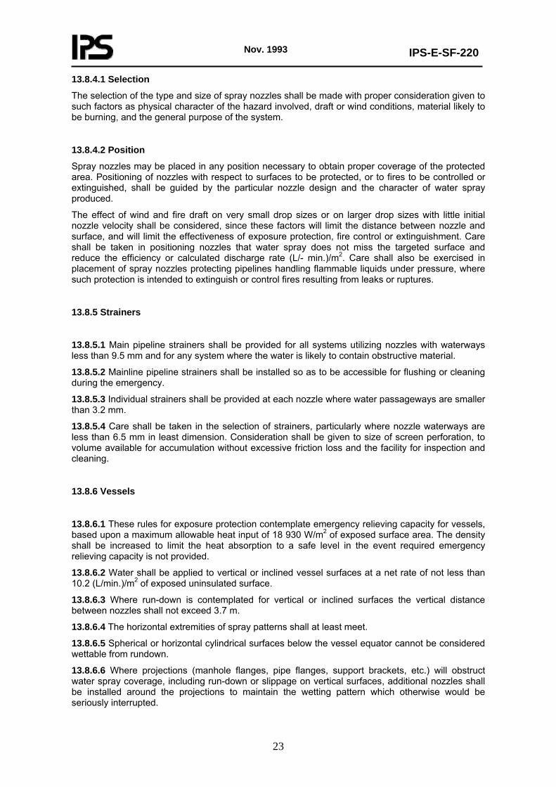
13.8.7 Structures and miscellaneous equipment
13.8.7.1 Horizontal, stressed (primary) structural steel members shall be protected by nozzles spaced not greater than 3 m on centers (preferably on alternate sides) and of such size and arrangement as to discharge not less than 4.1 (L/min.)/m2 over the wetted area. (See Fig. 1.)
Fig. 4
The wetted surface of structural member-beam or column is defined as one side of the web and the inside surface of one side of the flanges as shown above.
13.8.7.2 Vertical structural steel members shall be protected by nozzles spaced not greater than (3 m) on centers (preferably on alternate sides) and of such size and arrangement as to discharge not less than 10.2 (L/min.)/m2 over the wetted area. (See Fig. 4 above.)
13.8.7.3 Metal pipe, tubing and conduit runs shall be protected by water spray directed towards the horizontal plane surface projected by the bottom of the pipes or tubes.
Nozzles shall be selected to provide essentially total impingement on the entire horizontal surface area within which pipes or tubes are or could be located.
For single-level pipe racks, water spray nozzles shall discharge onto the underside of the pipe at a plan view density of 10.2(L/min.)/m2.
For two-level pipe racks, water spray nozzles shall discharge onto the underside of the lower level at a plan view density of 8.2 (L/min.)/m2 and additional spray nozzles shall discharge onto the underside of the upper level at a plan view density of 6.1(L/min.)/m2.
For three-, four-, and five-level pipe racks, water spray nozzles shall discharge onto the underside of the lowest level at a plan view density of 8.2 (L/min.)/m2 and additional spray nozzles shall discharge onto the underside of alternate levels at a plan view density of 6.1 (L/min.)/m2. Water spray shall be applied to the underside of the top level even if immediately above a protected level.
For pipe racks of six or more levels, water spray nozzles shall discharge onto the underside of the lowest level at a plan view density of 8.2 (L/min.)/m2 and additional spray nozzles shall discharge onto the underside of alternate levels at a plan view density of 4.1 (L/min.)/m2. Water spray shall be applied to the underside of the top level even if immediately above a protected level.
Water spray nozzles are to be selected and located such that extremities of water spray patterns shall at least meet and the discharge shall essentially be confined to the plan area of the pipe rack.
Spacing between nozzles shall not exceed 3 m and nozzles shall be no more than 0.8 m below the bottom of the pipe level being protected.
Consideration shall be given to obstruction to the spray patterns presented by pipe supporting steel.
Nov. 1993
IPS-E-SF-220
25
Where such interferences exist, nozzles shall be spaced within the bays.
Structural supports shall be protected in accordance with 13.8.7.1 and 13.8.7.2.
Exceptions:
1) Water spray protection with the same density as specified previously may be applied to the top of pipes on racks where water spray piping cannot be installed below the rack due to possibility of physical damage or space is inadequate for proper installation.
2) Vertically stacked piping may be protected by water spray directed at one side of the piping at a density of 6.1 (L/min.)/m2.
13.8.8 Transformers
13.8.8.1 Transformer protection shall contemplate essentially complete impingement on all exterior surfaces, except underneath surfaces which in lieu thereof may be protected by horizontal projection. The water shall be applied at a rate not less than 10.2 (L/min.)/m2 of projected area of rectangular prism envelope for the transformer and its appurtenances and not less than 6.1 (L/min.)/m2 on the expected nonabsorbing ground surface area of exposure. Additional application is needed for special configurations, conservator tanks, pumps, etc. Spaces greater than 305 mm in width between radiators, etc., shall be individually protected.
13.8.8.2 Water spray piping shall not be carried across the top of the transformer tank, unless impingement cannot be accomplished with any other configuration and provided the required distance from the live electrical components is maintained.
13.8.8.3 In order to prevent damage to energized bushings or lightning arrestors, water spray shall not envelop this equipment by direct impingement, unless so authorized by the manufacturer or manufacturer’s literature, and the N.I.O.C.
13.8.9 Belt conveyers
13.8.9.1 Drive unit
Water spray system shall be installed to protect the drive rolls, the take-up rolls, the power units and the hydraulic-oil unit. The rate of water application shall be 10.2 (L/min.)/m2 of roll and belt.
Nozzles shall be located to direct water spray onto the surfaces to extinguish fire in hydraulic oil, belt, or contents on the belt. Water spray impingement on structural elements shall be such as to provide protection against radiant heat or impinging flame.
13.8.9.2 Conveyer belt
Water spray system shall be installed to automatically wet the top belt, its contents, and the bottom return belt. Discharge patterns of water spray nozzles shall envelop, at a rate of [10.2 (L/min.)/m2] of top and bottom belt area, the structural parts and the idler-rolls supporting the belt. Water spray system protection shall be extended onto transfer belts, transfer equipment and transfer buildings beyond each transfer point.
Or, systems for the protection of adjacent belts or equipment shall be interlocked in such a manner that the feeding belt water spray system will automatically actuate the water spray system protecting the first segment of the downstream equipment.
Special consideration shall be given to the interior protection of the building, gallery, or tunnel housing the belt conveyer equipment.
Also, the exterior structural supports for galleries shall be protected from exposure such as fires in flammables located adjacent to the galleries.
Nov. 1993
IPS-E-SF-220
26
The effectiveness of belt conveyer protection is dependent upon rapid detection and appropriate interlocks between the detection system and the machinery.
13.9 Fire and Explosion Prevention
13.9.1 The system shall be able to function effectively for a sufficient time to dissolve, dilute, disperse, or cool flammable or hazardous materials. The possible duration of release of the materials shall be considered in the selection of duration times.
13.9.2 The rate of application shall be based upon experience with the product or upon test.
13.10 Size of System
Separate fire areas shall be protected by separate systems. Single systems shall be kept as small as practicable, giving consideration to the water supplies and other factors affecting reliability of the protection. The hydraulically designed discharge rate for a single system or multiple systems designed to operate simultaneously shall not exceed the available water supply.
13.11 Separation of Fire Areas
13.11.1 Separation of fire areas shall be by space, fire barriers, diking, special drainage, or by combination of these. In the separation of fire areas consideration shall be given to the possible flow of burning liquids before or during operation of the water spray systems.
13.11.2 Area drainage
a) Adequate provisions shall be made to promptly and effectively dispose of all liquids from the fire area during operation of all systems in the fire area. Such provisions shall be adequate for:
1) Water discharged from fixed fire protection systems at maximum flow conditions.
2) Water likely to be discharged by hose streams.
3) Surface water.
4) Cooling water normally discharged to the system.
b) There are four methods of disposal or containment:
1) Grading.
2) Diking.
3) Trenching.
4) Underground or enclosed drains.
c) The method used shall be determined by:
1) The extent of the hazard.
2) The clear space available.
3) The protection required.
Where the hazard is low, the clear space is adequate, and the degree of protection required is not great, grading is acceptable. Where these conditions are not present, consideration shall be given to dikes, trenching, or underground or enclosed drains.

Nov. 1993
IPS-E-SF-220
27
13.12 Valves
13.12.1 Shutoff valves
Each system shall be provided with a shutoff valve so located as to be readily accessible during a fire in the area the system protects or adjacent areas, or, for systems installed for fire prevention, during the existence of the contingency for which the system is installed.
13.12.1.1 Valves controlling water spray systems, except underground gate valves with roadway boxes, shall be supervised open by one of the following methods:
a) Central station, proprietary or remote station alarm service.
b) IocaI alarm service which will cause the sounding of an audible signal at a constantly attended point.
c) Locking valves open.
d) Sealing of valves and approved weekly recorded inspection when valves are located within fenced enclosures under the control of the owner.
13.12.2 Automatically controlled valves
13.12.2.1 Automatically controlled valves shall be as close to the hazard protected as accessibility during the emergency will permit, so that a minimum of piping is required between the automatic valve and the spray nozzles.
13.12.2.2 Remote manual tripping devices, where required, shall be conspicuously located where readily accessible during the emergency and adequately identified as to the system controlled.
13.13 Automatic Detection Equipment
The arrangement of automatic detection system for water spray shall be as defined in IPS-E-SF-260.
13.14 Hydraulic Calculation
Section 15 Appendix A of NFC gives details of hydraulic calculation and design of drainage for water spray system.

Nov. 1993
IPS-E-SF-220
28
APPENDIX A
TABLE 1 - PROCESS UNIT FIRE WATER REQUIREMENTS
TYPE OF PROCESS UNIT
MINIMUM FIRE WATER RATE M3/H US gpm
ATMOSPHERIC DISTILLATION, VACUUM, OR COMBINATION UNITS WITH UP TO 15,900 M3/d (100,000 bbl / d) THROUGHPUT; TREATING PLANTS; ASPHALT STILLS; OTHERS ATMOSPHERIC DISTILLATION, VACUUM, OR COMBINATION UNITS WITH 15,900 M3/d (100,000 bbl / d) OR HIGHER THROUGHPUT; CATALYTIC CRACKING UNITS LIGHT-END UNITS CONTAINING VOLATILE OILS AND HYDROGEN, SUCH AS REFORMERS, CATALYTIC DESULFUR- IZERS, AND ALKYLATION UNITS LUBE OIL UNITS AND BLENDING FACILITIES
٢٥٠٠ ٥٦٨ 900 4000 900 4000 454 2000
1.A Fixed Roof Tanks Containing High-Flash Liquids
1.A.1 When the stored product has a closed-cup flash point of 65°C (150°F) or higher, a fixed roof tank can be considered relatively safe. Then water for foam extinguishment is not required, provided the following conditions are met:
a) If the product is heated, there must be no possibility of the storage temperature exceeding either the flash point or 93°C (200°F).
b) There must be no possibility of hot oil streams entering the tank at temperatures above 93°C (200°F) or their flash point.
c) Cutter stock having a flash point below the storage temperature must never be pumped into the tank for blending purposes.
d) Sufficient fire water shall be available to cool exposed adjacent tankage in the event of ignition. Then the tank should be pumped out or allowed to burn out.
e) The product shall not be crude oil with boilover characteristics. If the product were crude, the fire would have to be extinguished before the heat wave reached water at the tank bottom.
f) Storage temperatures between 93°C (200°F) and 121°C (250°F) shall be avoided, as water lenses or water at the tank bottom may reach boiling temperature at any time, resulting in a serious frothover.
If the product is heated above 121°C (250°F) foam extinguishment cannot be accomplished and slopover will occur if foam is applied.
(to be continued)

Nov. 1993
IPS-E-SF-220
29
APPENDIX A (continued)
1.A.2 Floating roof tanks
1.A.2.1 Floating roof tanks are considered virtually ignitionproof, except for rim fires. Thus, there should be sufficient fire water to cool the shell and extinguish a rim fire.
1.A.3 Pressure storage
1.A.3.1 The water requirement for cooling pressure storage spheres or drums may exceed the maximum cone roof tank fire water requirement when spheres are of large diameter, or when a number of spheres or drums are closely spaced. See. However, when adjacent spheres are not over 15 m (50 ft.) in diameter and are at least 30m (100 ft.) apart, shell to shell, cooling of these spheres may be disregarded.
1.A.4 Low-pressure refrigerated storage
1.A.4.1 Water for monitor cooling streams should be available to cool the tank shell if it is exposed to fire. Water must not be applied directly to refrigerated LP-gas or cryogenic flammable liquid spills or spill fires, since much more rapid vapor evolution or increased fire intensity will result.
1.A.5 Cooling water for exposed tankage
1.A.5.1 During a tank or sphere fire, cooling streams may be needed for adjacent tankage. However, this does not apply to process units where flammable liquids are not contained in sufficient volume to generate enough heat to require cooling adjacent tankage. Allow at least two 57 m3/h (250 US gpm) cooling streams, or a total of 114 m3/h (500 US gpm), for each adjacent, unshielded fixed or floating roof tank within the following limits:
a) Within 15 m (50 ft.) of a burning tank or sphere of any size, regardless of wind direction.
b) Within one tank diameter and within a quadrant that will require the maximum amount of cooling water for tanks that fall within the quadrant.
c) Within 45 m (150 ft.) of a sphere and within the most congested quadrant.
1.A.6 Fire water capacity vs crude throughput
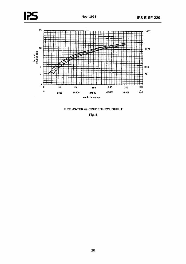
1.A.6.1 Fig. 5 shows fire water capacity, in cubic meters per hour (thousands of US gallons per minute), plotted against crude throughput, in cubic meters per day (thousands of barrels per calendar day). The curve represents an average of data collected from plants all over the world. This curve can be used as a guide to the required quantity when calculating refinery fire water capacity by the methoprescribed in this Section.
1.A.7 Fire water s9,lupply
1.A.7.1 Fire water should be obtained from an unlimited source, such as a natural body of water. When this is not possible, the supply should always be available in a storage tank or reservoir.
(to be continued)
Nov. 1993
IPS-E-SF-220
30
FIRE WATER vs CRUDE THROUGHPUT
Fig. 5