engineering test report number: …circuitco electronics 1380 presidential, suite 100 richardson,...
TRANSCRIPT
ENGINEERING TEST REPORT
NUMBER: 10216476EEU1
ON
Model Name:
BB-BONE-000
IN ACCORDANCE WITH: EN 61326-2-1: 2006
FOR CLASS B EQUIPMENT
TESTED FOR:
Circuitco Electronics 1380 Presidential, Suite 100 Richardson, Texas 75081
TESTED BY: Nemko USA, Inc.
802 N. Kealy Lewisville, Texas 75057-3136
Number of Pages: 45
TESTED BY: DATE: 02-Nov-2011 Brian, Boyea, EMC Engineer
APPROVED BY: DATE: 14-Nov-2011 Arturo Ruvalcaba, EMC Engineer
Nemko USA, Inc. authorizes the above named company to reproduce this report provided it is reproduced in its entirety, for use by the
company’s employees only.
This report must not be used to claim product certification, approval, or endorsement by NVLAP, NIST, or any agency of the Federal Government. Nemko USA, Inc. is a NVLAP accredited laboratory.
Any use which a third party makes of this report, or any reliance on or decisions to be made based on it, are the responsibility of such third parties. Nemko USA, Inc. accepts no responsibility for damages, if any, suffered by any third party as a result of decisions made or actions
based on this report. This report applies only to the items tested.

EN 61326-2-1: 2006 FOR CLASS B Nemko USA, Inc. REPORT NO.: 10216476EEU1
EQUIPMENT: Development Board ______________________________________________________________________________________
Page 2 of 45
Table of Contents Section 1. Summary of Test Results ............................................................. 3
Section 2. Equipment Under Test (E.U.T.) ..................................................... 5
Section 3. Equipment Configuration ............................................................. 7
Section 4. Conducted Emissions (Mains ports) ........................................... 8
Section 5. Radiated Emissions .................................................................... 13
Section 6. Harmonics .................................................................................... 18
Section 7. Flicker ........................................................................................... 19
Section 8. Electrostatic Discharge Immunity .............................................. 20
Section 9. Radiated Electromagnetic Immunity .......................................... 24
Section 10. Electrical Fast Transient / Burst ................................................. 28
Section 11. Surge Immunity ........................................................................... 29
Section 12. RF Common Mode (A.M.) ............................................................ 30
Section 13. Magnetic Immunity ...................................................................... 31
Section 14. Voltage Dips and Interruptions .................................................. 32
Section 15. Test Methods and Block Diagrams. ........................................... 33
Section 16. Performance Criteria. .................................................................. 45

EN 61326-2-1: 2006 FOR CLASS B Nemko USA, Inc. REPORT NO.: 10216476EEU1
EQUIPMENT: Development Board ______________________________________________________________________________________
Page 3 of 45
Section 1. Summary of Test Results
General: All measurements are traceable to national standards. These tests were conducted on a sample of the equipment for the purpose of demonstrating compliance with EN 61326-2-1: 2006, Electrical equipment for measurement control and laboratory use for Class B equipment using the following test standards as test methodologies: All tests were performed using measurement procedure CISPR 16. Frequencies were initially identified in a semi-anechoic chamber. Amplitude measurements were made in a semi-anechoic chamber.
Abstract: Emissions:
Name of Test Basic Standard Results Conducted Emissions (Mains port) EN 61326-2-1: 2006 Complies Radiated Emissions EN 61326-2-1: 2006 Complies Harmonics EN 61000-3-2: 2006 Not Tested Note 1Flicker EN 61000-3-3: 2008 Not Tested Note 1
Note 1: The EUT is powered by the host computer.

EN 61326-2-1: 2006 FOR CLASS B Nemko USA, Inc. REPORT NO.: 10216476EEU1
EQUIPMENT: Development Board ______________________________________________________________________________________
Page 4 of 45
Abstract: - Continued
Immunities:
Name of Test Basic Standard Test
Specification Performance Results
Electrostatic Discharge
EN61000-4-2: 2001 ±4kV Contact Discharge ±8kV Air Discharge
B Complies
Radiated Electro-magnetic Field
EN61000-4-3: 2006 80 to 1000 MHz 1.4GHz to 2.7GHz 80% AM @ 1 kHz 10V/m 2.0GHz to 2.7GHz 80% AM @ 1 kHz 3V/m
A Complies
Electrical Fast Transients / Burst
EN61000-4-4: 2004 ±0.5 kV on I/O Signal
and Control Lines ±1kV and ±2kV on Power Supply
B Not Tested
Note 1
Surge Immunity EN61000-4-5: 2006 Line to Earth ±2kV Line to Line ±1kV
B Not Tested Note 1
RF Conducted Immunity
EN61000-4-6: 2003 150 kHz to 80MHz 3 Vrms 80% Mod.
A Not Tested Note 1
Magnetic Immunity EN61000-4-8: 2000 3A/m @ 50Hz (For CRT 1A/M)
A Not Tested Note 2
Voltage Dips and Interruptions
EN61000-4-11: 2004 0% Reduction (1 cycle) 40% Reduction (10/12 cycles) 70% Reduction (25/30 cycles) 0% Reduction (250/300 cycles)
B
Not Tested Note 1
Note 1: The EUT is powered by the host computer. Note 2: The EUT does not have any components susceptible to Magnetic Immunity. THE FOLLOWING DEVIATIONS FROM, ADDITIONS TO, OR EXCLUSIONS FROM THE TEST SPECIFICATIONS HAVE BEEN MADE: None

EN 61326-2-1: 2006 FOR CLASS B Nemko USA, Inc. REPORT NO.: 10216476EEU1
EQUIPMENT: Development Board ______________________________________________________________________________________
Page 5 of 45
Section 2. Equipment Under Test (E.U.T.)
Manufacturer: Circuitco Electronics
Name: BeagleBone
Model Number: BB-BONE-000 Serial Number: 22 Part Number: BB-BONE-000
Production Status: Pre-Production
E.U.T. Arrival Date: 11/2/11
Description of E.U.T.
Development Board
Modifications Incorporated in E.U.T.: None
Justification: The E.U.T. was configured for testing as per typical installation. Position and bundling of cables were investigated to establish maximum amplitude of emissions.
Exercise Program: The E.U.T. exercise program used during radiated and conducted testing was designed to exercise the various system components in a manner similar to typical use. The EUT was in the following exercise mode: Powered on running
Clock, Oscillator, Highest Frequencies Utilized:
25MHz, 24MHz, 48MHz, 100MHz

EN 61326-2-1: 2006 FOR CLASS B Nemko USA, Inc. REPORT NO.: 10216476EEU1
EQUIPMENT: Development Board ______________________________________________________________________________________
Page 6 of 45
E.U.T. Photographs:

EN 61326-2-1: 2006 FOR CLASS B Nemko USA, Inc. REPORT NO.: 10216476EEU1
EQUIPMENT: Development Board ______________________________________________________________________________________
Page 7 of 45
Section 3. Equipment Configuration
Item Description(A) Laptop(B) Ethernet Cable(C) USB Cable(D) 2GB Thumbdrive(E) EUT(F) SD Card(G)(H)(I)(J)
Item Type Qtyi.ii. 5 1
Description
USB Cable to the PC
Kodak 2GBBeagleBone S/N 22 Rev BKingston 2GB
EUT Power and Interfaces:
Equipment Configuration List:Identification: (M/N #, S/N #, P/N #, Rev.)Dell Lattitude S/N E6410 15665268 601Fry's Qualtek 3021003-03

EN 61326-2-1: 2006 FOR CLASS B Nemko USA, Inc. REPORT NO.: 10216476EEU1
EQUIPMENT: Development Board ______________________________________________________________________________________
Page 8 of 45
Section 4. Conducted Emissions (Mains ports)
Purpose: The test is intended to demonstrate the compliance of the Equipment Under Test (E.U.T.) to the limits for conducted disturbance as defined by EN 61326-2-1: 2006, Class B. Specification Limits: Limits for conducted disturbance at the mains ports
Frequency Range (MHz) Quasi-peak Limits (dBuV)
Average Limits (dBuV)
0.15 to 0.50 66 - 56 56 - 46 0.50 to 5.00 56 46 5.00-30.0 60 50
Test Method: See Section 15.
EN 61326-2-1: 2006 FOR CLASS B Nemko USA, Inc. REPORT NO.: 10216476EEU1
EQUIPMENT: Development Board ______________________________________________________________________________________
Page 9 of 45
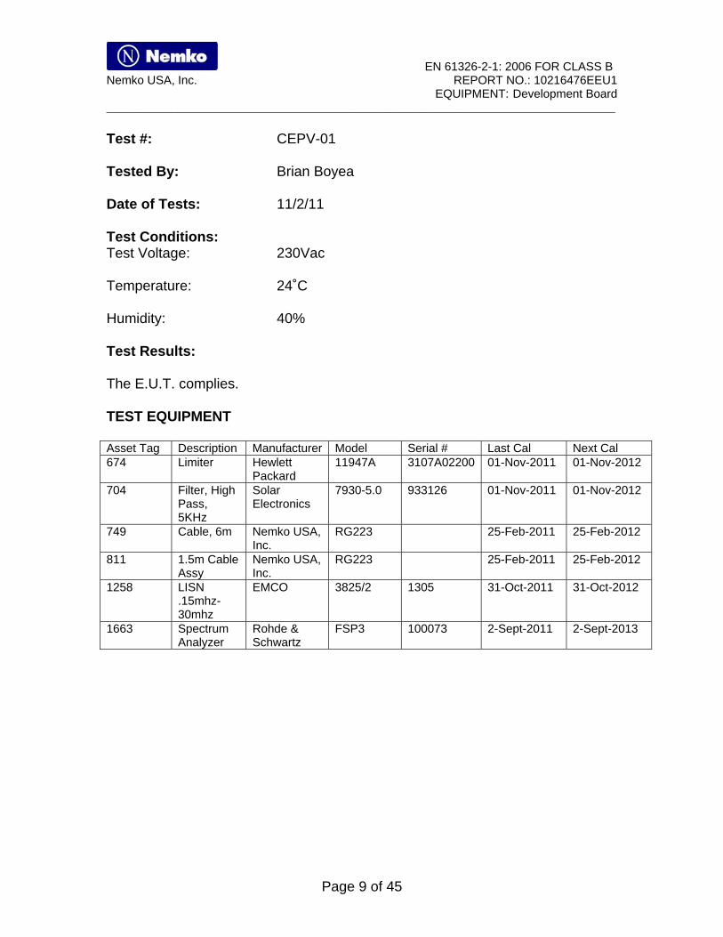
Test #: CEPV-01 Tested By: Brian Boyea Date of Tests: 11/2/11 Test Conditions: Test Voltage: 230Vac Temperature: 24˚C Humidity: 40% Test Results: The E.U.T. complies. TEST EQUIPMENT Asset Tag Description Manufacturer Model Serial # Last Cal Next Cal 674 Limiter Hewlett
Packard 11947A 3107A02200 01-Nov-2011 01-Nov-2012
704 Filter, High Pass, 5KHz
Solar Electronics
7930-5.0 933126 01-Nov-2011 01-Nov-2012
749 Cable, 6m Nemko USA, Inc.
RG223 25-Feb-2011 25-Feb-2012
811 1.5m Cable Assy
Nemko USA, Inc.
RG223 25-Feb-2011 25-Feb-2012
1258 LISN .15mhz-30mhz
EMCO 3825/2 1305 31-Oct-2011 31-Oct-2012
1663 Spectrum Analyzer
Rohde & Schwartz
FSP3 100073 2-Sept-2011 2-Sept-2013

EN 61326-2-1: 2006 FOR CLASS B Nemko USA, Inc. REPORT NO.: 10216476EEU1
EQUIPMENT: Development Board ______________________________________________________________________________________
Page 10 of 45
Test Data Conducted Emissions Line 1
Nemko Line 1 Final QP/AVG Operator: Brian Frequency FCCB FCCB AVG AVG QP QP
MHz QP LIMIT
AVG LIMIT
Meas Margin Meas Margin
3.37 56.00 46.00 29.70 -16.30 40.25 -15.75 3.66 56.00 46.00 29.33 -16.67 42.02 -13.98 3.72 56.00 46.00 29.82 -16.18 42.58 -13.42 3.66 56.00 46.00 29.33 -16.67 42.02 -13.98 3.37 56.00 46.00 29.70 -16.30 40.25 -15.75
Conducted Emissions Fully Operational

EN 61326-2-1: 2006 FOR CLASS B Nemko USA, Inc. REPORT NO.: 10216476EEU1
EQUIPMENT: Development Board ______________________________________________________________________________________
Page 11 of 45
Line 2
Nemko Line 2 Final QP/Avg Operator: Brian Frequency FCCB FCCB AVG AVG QP QP
MHz QP Limit
AVG Limit
Meas Margin Meas Margin
3.41 56.00 46.00 27.93 -18.07 42.39 -13.61 3.47 56.00 46.00 27.97 -18.03 41.54 -14.46 3.48 56.00 46.00 27.87 -18.14 42.00 -14.00 3.54 56.00 46.00 31.73 -14.27 45.24 -10.76 4.17 56.00 46.00 30.91 -15.10 34.92 -21.08
Conducted Emissions Fully Operational

EN 61326-2-1: 2006 FOR CLASS B Nemko USA, Inc. REPORT NO.: 10216476EEU1
EQUIPMENT: Development Board ______________________________________________________________________________________
Page 12 of 45
Test Photographs

EN 61326-2-1: 2006 FOR CLASS B Nemko USA, Inc. REPORT NO.: 10216476EEU1
EQUIPMENT: Development Board ______________________________________________________________________________________
Page 13 of 45
Section 5. Radiated Emissions
Purpose: The test is intended to demonstrate the compliance of the Equipment Under Test (E.U.T.) to the limits for radiated emissions as defined by EN 61326-2-1: 2006, Class B. Specification Limits: Limits for radiated disturbance of Class B
Frequency range Quasi-peak Limits dB (V/m) MHz @ 3 m @ 10 m
30 to 230 40 30.0 230 to 1000 47 37.0
Notes: 1. The lower limit shall apply at the transition frequency. 2. Additional provisions may be required for cases where interference occurs. 3. The 3m limits are calculated as follows: L3 = L10 * 10/3 where L10 is the limit at 10m specified in V/m
Test Method: See Section 15.

EN 61326-2-1: 2006 FOR CLASS B Nemko USA, Inc. REPORT NO.: 10216476EEU1
EQUIPMENT: Development Board ______________________________________________________________________________________
Page 14 of 45
Test #: REHE-01 Tested By: Brian Boyea Date of Tests: 11/2/11 Test Conditions: Test Voltage 230 Vac Temperature: 27˚C Humidity: 25% Test Results: The E.U.T. complies. TEST EQUIPMENT Asset Tag Description Manufacturer Model Serial # Last Cal Next Cal 1 3m Semi-
Anechoic Chamber
Nemko USA, Inc.
Chamber 1 26-Sept-2011 26-Sept-2012
1016 Preamplifier Hewlett Packard
8449A 2749A00159 20-July-2011 20-July-2012
1025 Preamplifier, 25dB
Nemko USA, Inc.
LNA25 399 23-Feb-2011 23-Feb-2012
1304 Antenna, Horn
Electro Metrics
RGA-60 6151 24-Nov-2010 24-Nov-2012
1480 Antenna, Bilog
Schaffner-Chase
CBL6111C 2572 19-Jan-2011 19-Jan-2012
1767 Receiver, EMI Test 20Hz - 26.5 GHz - 150 - +30 dBm LCD
Rohde & Schwartz
ESIB26 837491/0002 01-Dec-2010 01-Dec-2011
1783 Cable Assy, 3m Chamber
Nemko Chanmber 26-Sept-2011 26-Sept-2012

EN 61326-2-1: 2006 FOR CLASS B Nemko USA, Inc. REPORT NO.: 10216476EEU1
EQUIPMENT: Development Board ______________________________________________________________________________________
Page 15 of 45
Test Data –Radiated Emissions, Electric Field, Test#REHE-01
Horizontal
Nem ko
EN5 5 0 2 2 Cla s s B 3 0 M Hz -1 GHz
Horizontal Scan
3 0 .0 M 2 3 0 .0 M 4 3 0 .0 M 6 3 0 .0 M 8 3 0 .0 M
Frequency (Hz)
0
1 0 .0
2 0 .0
3 0 .0
4 0 .0
5 0 .0
6 0 .0
7 0 .0
8 0 .0
Lim
it L
evel
(d
Bu
V/m
)
Company: Ci rcui tco
Model Number:
08:28:14 AM, Wednesday, November 02, 2011
Operator: Bri an
Scan
EN55022 B Li mi t
Scan
Peaks
Peaks
Vertical
Nem ko
EN5 5 0 2 2 Cla s s B 3 0 M Hz -1 GHz
Verti cal Scan
3 0 .0 M 2 3 0 .0 M 4 3 0 .0 M 6 3 0 .0 M 8 3 0 .0 M
Frequency
0
1 0 .0
2 0 .0
3 0 .0
4 0 .0
5 0 .0
6 0 .0
7 0 .0
8 0 .0
Am
pli
tud
e (d
bu
V/m
)
Company: Ci rcui tco
Model Number:
08:32:09 AM, Wednesday, November 02, 2011
Operator: Bri an
Scan
EN55022 B Li mi t
Scan
Peaks
Peaks

EN 61326-2-1: 2006 FOR CLASS B Nemko USA, Inc. REPORT NO.: 10216476EEU1
EQUIPMENT: Development Board ______________________________________________________________________________________
Page 16 of 45
Nemko, Lewisville, TX FCC 3 Meter Chamber Final Quasi Peak Measurements Operator: Brian Frequency Limit Horizontal QP Vertical VerticalMHz QP Margin QP Margin
51.94 40.00 29.38 -10.6395.77 40.00 28.36 -11.64
108.82 40.00 31.05 -8.95 186.27 40.00 26.21 -13.79 250.01 47.00 44.81 -2.19 42.72 -4.28375.03 47.00 36.57 -10.43 455.75 47.00 28.43 -18.57499.99 47.00 44.44 -2.56 500.03 47.00 32.94 -14.06625.01 47.00 38.47 -8.53 750.01 47.00 34.36 -12.64999.98 47.00 43.17 -3.83 41.85 -5.15
30 MHz to 1GHz was the spectrum searched. RBW = 120kHz VBW = 120kHz RBW = 120kHz

EN 61326-2-1: 2006 FOR CLASS B Nemko USA, Inc. REPORT NO.: 10216476EEU1
EQUIPMENT: Development Board ______________________________________________________________________________________
Page 17 of 45
Test Photographs - Test # REHE-01

EN 61326-2-1: 2006 FOR CLASS B Nemko USA, Inc. REPORT NO.: 10216476EEU1
EQUIPMENT: Development Board ______________________________________________________________________________________
Page 18 of 45
Section 6. Harmonics Not Tested: The EUT is powered from the host computer. Purpose: The test is intended to demonstrate the compliance of the Equipment Under Test (E.U.T.) to the limits on the magnitude of harmonic currents created by the equipment, as specified in EN 61000-3-2: 2006. Specification Limits: For Class A equipment, the harmonics of the input current shall not exceed the maximum permissible values given in Table 1 multiplied by a factor of 1.5. Table 1 – Limits for Class A equipment.
Harmonic order n
Maximum permissible Harmonic current
A Odd harmonics
3 5 7 9 11 13
15 < n < 39
2.30 1.14 0.77 0.40 0.33 0.21
0.15 15/n Even harmonics
2 4 6
8 < n < 40
1.08 0.43 0.30
0.23 8/n Test Method:
Test Information: Test Conditions: Test #: HARM-01 Test Voltage: 230 Vac Tested By: Temperature: 23˚C Date of Tests: Humidity: 34%
Test Results:

EN 61326-2-1: 2006 FOR CLASS B Nemko USA, Inc. REPORT NO.: 10216476EEU1
EQUIPMENT: Development Board ______________________________________________________________________________________
Page 19 of 45
Section 7. Flicker Not Tested: The EUT is powered from the host computer. Purpose: The test is intended to demonstrate the compliance of the Equipment Under Test (E.U.T.) to the limits on the level of voltage fluctuations produced by the equipment, as specified in EN 61000-3-3: 2008.
Specification Limits: The limits shall be applicable to voltage fluctuations and flicker at the supply terminals of the equipment under test. The following limits apply: The value of Pst shall not be greater than 1.0. The value of PIt shall not be greater than 0.65. The relative steady-state voltage change, dc, shall not exceed 3%. The maximum relative voltage change, dmax’ shall not exceed 4%. The value of d(t) during a voltage change shall not exceed 3% for more than
200 ms. If voltage changes are caused by manual switching or occur less frequently than once per hour, the Pst and PIt requirements shall not be applicable. The three requirements related to voltage changes shall be applicable with the previously mentioned voltage values, multiplied by a factor of 1.33.
Test Information: Test Conditions: Test #: Flicker-01 Test Voltage: 230 Vac Tested By: Temperature: 23˚C Date of Tests: Humidity: 34%
Test Results:

EN 61326-2-1: 2006 FOR CLASS B Nemko USA, Inc. REPORT NO.: 10216476EEU1
EQUIPMENT: Development Board ______________________________________________________________________________________
Page 20 of 45
Section 8. Electrostatic Discharge Immunity Purpose: The test is intended to demonstrate the compliance of the Equipment Under Test (E.U.T.) to electrostatics discharges. Minimum Performance Criteria B
Performance Criteria: Criteria A: The apparatus shall continue to operate as intended. No degradation of performance or loss of function is allowed below a performance level specified by the manufacturer, when the apparatus is used as intended. The performance level may be replaced by permissible loss of performance. If the minimum performance level or the permissible performance loss is not specified by the manufacturer then either of these may be derived from the product description and documentation and what the user may reasonably expect from the apparatus if used as intended. Criteria B: The apparatus shall continue to operate as intended after the test. No degradation of performance or loss of function is allowed below a performance level specified by the manufacturer, when the apparatus is used as intended. The performance level may be replaced by a permissible loss of performance. During the test, degradation of performance is however allowed. No change of actual operating state or stored data is allowed. If the minimum performance level or the permissible performance loss is not specified by the manufacturer then either of these may be derived from the product description and documentation and what the user may reasonably expect from the apparatus if used as intended. Criteria C: Temporary loss of function is allowed, provided the function is self-recoverable or can be restored by the operation of the controls.

EN 61326-2-1: 2006 FOR CLASS B Nemko USA, Inc. REPORT NO.: 10216476EEU1
EQUIPMENT: Development Board ______________________________________________________________________________________
Page 21 of 45
Test #: ESDI-01 Tested By: Brian Boyea Date of Tests: 11/2/11 Test Conditions: Test Voltage: 230 Vac Temperature: 23˚C Humidity: 35% Test Results: The E.U.T. complies. The E.U.T. meets Performance Criteria A. TEST EQUIPMENT
Asset Number
Description Manufacturer Model Number
Serial Number
Last Cal Cal Due
1247 2 x 470k Ohm Ground Strap
Nemko USA, Inc. N/R
1738 All-In-One ESD3000 Gun EMC-PARTNER/HV Technologies
ESD3000 294 18-Oct-2011 18-Oct-2012
1752 All-In-One ESD DN1 Network, 150 pF, 330 ohm
EMC-PARTNER/HV Technologies
ESD3000DN1 80 18-Oct-2011 18-Oct-2012
1754 All-In-One Relay Module (Tip)
EMC-PARTNER/HV Technologies
ESD3000RM32 99 18-Oct-2011 18-Oct-2012

EN 61326-2-1: 2006 FOR CLASS B Nemko USA, Inc. REPORT NO.: 10216476EEU1
EQUIPMENT: Development Board ______________________________________________________________________________________
Page 22 of 45
Test Data –Electrostatic Discharge Test#ESDI-01
Electrostatic Discharge Data
Complete X Job # : 10216476 Test # : ESDI-01Preliminary Page 1 of 1
Client Name : Circuitco Electronics EUT Name : Beagle BoneEUT Model # : BB-BONE-000EUT Part # : BB-BONE-000EUT Serial # : 22 EUT Config. : Powered on
Specification : EN 61326-1 Temp. (deg. C) : 24 Reference : EN 61000-4-2ESD Generator# 1754 Humidity (%) : 35 Date : 11/02/11Cable#: 1247 EUT Voltage : 230 Vac Grnd Strap: 1025k ohms
EUT Freq: Staff : Brian Boyea1. HCP X Barometric Pressure 1014 Photo ID: ESDI-012. VCP X Phase: N/A Performance Criteria: B3 USB Cable Location: Lab 3 Table Top or Floor4. 7. 10.5. 8. 116. 9. 12.Does product have any type of insulated coating on exterior surfaces? Yes No X
If yes, indicate where:
Test ESD Polarity Contact Application Effect Effects Pass
Point Level or Quantity Qty Type or
(kV) Air Fail Comments1 2 +/- Contact 20 0 None Pass1 4 +/- Contact 20 0 None Pass2 2 +/- Contact 20 0 None Pass2 4 +/- Contact 20 0 None Pass3 2 +/- Air 20 0 None Pass3 4 +/- Air 20 0 None Pass3 8 +/- Air 20 0 None Pass
..\EMCShare\AUTOMATE\DATASHTS\ESD Rev C.xls Document Control #EMC DS IM ESD

EN 61326-2-1: 2006 FOR CLASS B Nemko USA, Inc. REPORT NO.: 10216476EEU1
EQUIPMENT: Development Board ______________________________________________________________________________________
Page 23 of 45
Test Photographs - Test # ESDI-01

EN 61326-2-1: 2006 FOR CLASS B Nemko USA, Inc. REPORT NO.: 10216476EEU1
EQUIPMENT: Development Board ______________________________________________________________________________________
Page 24 of 45
Section 9. Radiated Electromagnetic Immunity Purpose: The test is intended to demonstrate the compliance of the Equipment Under Test (E.U.T.) to radiated electromagnetic field energy. Minimum Performance Criteria A
Performance Criteria: Criteria A: The apparatus shall continue to operate as intended. No degradation of performance or loss of function is allowed below a performance level specified by the manufacturer, when the apparatus is used as intended. The performance level may be replaced by permissible loss of performance. If the minimum performance level or the permissible performance loss is not specified by the manufacturer then either of these may be derived from the product description and documentation and what the user may reasonably expect from the apparatus if used as intended. Criteria B: The apparatus shall continue to operate as intended after the test. No degradation of performance or loss of function is allowed below a performance level specified by the manufacturer, when the apparatus is used as intended. The performance level may be replaced by a permissible loss of performance. During the test, degradation of performance is however allowed. No change of actual operating state or stored data is allowed. If the minimum performance level or the permissible performance loss is not specified by the manufacturer then either of these may be derived from the product description and documentation and what the user may reasonably expect from the apparatus if used as intended. Criteria C: Temporary loss of function is allowed, provided the function is self-recoverable or can be restored by the operation of the controls. Test Method: See Section 15.

EN 61326-2-1: 2006 FOR CLASS B Nemko USA, Inc. REPORT NO.: 10216476EEU1
EQUIPMENT: Development Board ______________________________________________________________________________________
Page 25 of 45
Test #: RIHE-01 Tested By: Brian Boyea Date of Tests: 11/2/11 Test Conditions: Test Voltage: 230 Vac Temperature: 23˚C Humidity: 30% Test Results: The E.U.T. complies. The E.U.T. meets Performance Criteria A. TEST EQUIPMENT
Asset Number
Description Manufacturer Model Number Serial Number
Last Cal Cal Due
1724 Field Monitor ETS-Lindgren HI-6100 00069660 NR N/A 1765 Log Antenna AR AT1080 0325162 NR N/A 1770 Signal Generator R & S SMIQ 06L 1125.5555.36 NR N/A
412 RF AMPLIFIER Amplifier Research 100W1000M1A 21233 NR N/A
1836 Amp 300W AR 300T2G8 325204 NR N/A 1862 Amp 250W AR 250T1G3 330041 NR N/A 1793 Field probe ETS-Lindgren HI-6005 00090030 12/23/10 12/23/11 1483 Cable 4m Storm PR90-010-144 N/A NR N/A 1625 CABLE, 18 ft MEGAPHASE 10311 1GVT4 N/A NR N/A 1041 CABLE 3m Nemko Semi-Flex NR N/A 1066 CABLE 4m Storm PR90-010-144 NR N/A 1304 Horn Antenna Electro Metrics RGA-60 6151 11/24/10 11/24/11

EN 61326-2-1: 2006 FOR CLASS B Nemko USA, Inc. REPORT NO.: 10216476EEU1
EQUIPMENT: Development Board ______________________________________________________________________________________
Page 26 of 45
Test Data –Radiated Electromagnetic Field Test#RIHE-01
Radiated Immunity Electric Field Test Data
Complete X Job # : 10216476 Test # : RIHE-01Preliminary Page 1 of 1
Client Name : Circuitco Electronics EUT Name : Beagle BoneEUT Model # : BB-BONE-000EUT Part # : BB-BONE-000EUT Serial # : 22EUT Config. : Powered on
Specification : EN 61326-1 Reference : ETSI EN 61000-4-3Signal Gen.#: 1770 Temp. (deg. C) : 23 Date : 11/02/11Signal Gen.#: Humidity (%) : 30 Time :Cable#: 1483 EUT Voltage : 230 Vac Staff : Brian BoyeaCable#: 1989 EUT Frequency : Photo ID:Cable#: 1041 Barometric Pressure: 1017 Performance Criteria: AAmp#: 412 Location: ANC 3 Table Top or Floor:Amp#: 1836 Monitor#: 1724 Sweep rate: N/AAnalyzer #: 1862 Probe# 1757 Step Size: 1%Cable#: 1066 Cable#: 1625 Modulated: 80%Antenna#: 1765 Directional Cpler.:# Cable#:Antenna#: 1304 Cable#: Cable#:
Freq. Freq. Field Effect Effects Polarity Front PassStart Stop Strength Qty Type or or(MHz) (MHz) (V/m) (H or V) Back Fail Comments:
80 1000 10 0 N/A H Front Pass80 1000 10 0 N/A V Rear Pass
1400 2000 3 0 N/A H Front Pass1400 2000 3 0 N/A V Rear Pass2000 2700 3 0 N/A H Front Pass2000 2700 3 0 N/A V Rear Pass
..\EMCShare\AUTOMATE\DATASHTS\Radiated Immunity Electric Rev C.xls Document Control #EMC DS IM RAD ELEC
EN 61326-2-1: 2006 FOR CLASS B Nemko USA, Inc. REPORT NO.: 10216476EEU1
EQUIPMENT: Development Board ______________________________________________________________________________________
Page 27 of 45
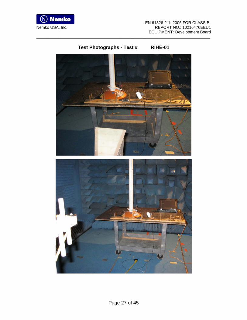
Test Photographs - Test # RIHE-01

EN 61326-2-1: 2006 FOR CLASS B Nemko USA, Inc. REPORT NO.: 10216476EEU1
EQUIPMENT: Development Board ______________________________________________________________________________________
Page 28 of 45
Section 10. Electrical Fast Transient / Burst Not tested: The EUT is powered by the host computer and no cable >3m. Purpose: The test is intended to demonstrate the compliance of the Equipment Under Test (E.U.T.) to repetitive electrical fast transients (bursts), on supply, signal, or control lines. Minimum Performance Criteria B
Performance Criteria: Criteria A: The apparatus shall continue to operate as intended. No degradation of performance or loss of function is allowed below a performance level specified by the manufacturer, when the apparatus is used as intended. The performance level may be replaced by permissible loss of performance. If the minimum performance level or the permissible performance loss is not specified by the manufacturer then either of these may be derived from the product description and documentation and what the user may reasonably expect from the apparatus if used as intended. Criteria B: The apparatus shall continue to operate as intended after the test. No degradation of performance or loss of function is allowed below a performance level specified by the manufacturer, when the apparatus is used as intended. The performance level may be replaced by a permissible loss of performance. During the test, degradation of performance is however allowed. No change of actual operating state or stored data is allowed. If the minimum performance level or the permissible performance loss is not specified by the manufacturer then either of these may be derived from the product description and documentation and what the user may reasonably expect from the apparatus if used as intended. Criteria C: Temporary loss of function is allowed, provided the function is self-recoverable or can be restored by the operation of the controls. Test Method: See Section 15.

EN 61326-2-1: 2006 FOR CLASS B Nemko USA, Inc. REPORT NO.: 10216476EEU1
EQUIPMENT: Development Board ______________________________________________________________________________________
Page 29 of 45
Section 11. Surge Immunity Not tested: The EUT is powered by the host computer. Purpose: The test is intended to demonstrate the compliance of the Equipment Under Test (E.U.T.) to electrical surge on supply lines and I/O lines. Minimum Performance Criteria B
Performance Criteria: Criteria A: The apparatus shall continue to operate as intended. No degradation of performance or loss of function is allowed below a performance level specified by the manufacturer, when the apparatus is used as intended. The performance level may be replaced by permissible loss of performance. If the minimum performance level or the permissible performance loss is not specified by the manufacturer then either of these may be derived from the product description and documentation and what the user may reasonably expect from the apparatus if used as intended. Criteria B: The apparatus shall continue to operate as intended after the test. No degradation of performance or loss of function is allowed below a performance level specified by the manufacturer, when the apparatus is used as intended. The performance level may be replaced by a permissible loss of performance. During the test, degradation of performance is however allowed. No change of actual operating state or stored data is allowed. If the minimum performance level or the permissible performance loss is not specified by the manufacturer then either of these may be derived from the product description and documentation and what the user may reasonably expect from the apparatus if used as intended. Criteria C: Temporary loss of function is allowed, provided the function is self-recoverable or can be restored by the operation of the controls.

EN 61326-2-1: 2006 FOR CLASS B Nemko USA, Inc. REPORT NO.: 10216476EEU1
EQUIPMENT: Development Board ______________________________________________________________________________________
Page 30 of 45
Section 12. RF Common Mode (A.M.) Not tested: The EUT is powered by the host computer and no cable >3m. Purpose: The test is intended to demonstrate the compliance of the Equipment Under Test (E.U.T.) to the electromagnetic fields generated from intentional radiators. Minimum Performance Criteria A
Performance Criteria: Criteria A: The apparatus shall continue to operate as intended. No degradation of performance or loss of function is allowed below a performance level specified by the manufacturer, when the apparatus is used as intended. The performance level may be replaced by permissible loss of performance. If the minimum performance level or the permissible performance loss is not specified by the manufacturer then either of these may be derived from the product description and documentation and what the user may reasonably expect from the apparatus if used as intended. Criteria B: The apparatus shall continue to operate as intended after the test. No degradation of performance or loss of function is allowed below a performance level specified by the manufacturer, when the apparatus is used as intended. The performance level may be replaced by a permissible loss of performance. During the test, degradation of performance is however allowed. No change of actual operating state or stored data is allowed. If the minimum performance level or the permissible performance loss is not specified by the manufacturer then either of these may be derived from the product description and documentation and what the user may reasonably expect from the apparatus if used as intended. Criteria C: Temporary loss of function is allowed, provided the function is self-recoverable or can be restored by the operation of the controls.

EN 61326-2-1: 2006 FOR CLASS B Nemko USA, Inc. REPORT NO.: 10216476EEU1
EQUIPMENT: Development Board ______________________________________________________________________________________
Page 31 of 45
Section 13. Magnetic Immunity Not tested: The EUT has no components susceptible to Magnetic Immunity. Purpose: The test is intended to demonstrate the compliance of the Equipment Under Test (E.U.T.) to magnetic disturbances at power frequency related to industrial installations and power plants. Minimum Performance Criteria A Test Method: See Section 16.
Test Information: Test Conditions: Test #: RILM-01 Test Voltage: 230 Vac Tested By: Temperature: 23˚C Date of Tests: Humidity: 33%
Test Results:
EN 61326-2-1: 2006 FOR CLASS B Nemko USA, Inc. REPORT NO.: 10216476EEU1
EQUIPMENT: Development Board ______________________________________________________________________________________
Page 32 of 45
Section 14. Voltage Dips and Interruptions Not tested: The EUT is powered by the host computer Purpose: The test is intended to demonstrate the compliance of the Equipment Under Test (E.U.T.) when subjected to voltage dips, short interruptions, and voltage variations.
Performance Criteria:
Criteria A: The apparatus shall continue to operate as intended. No degradation of performance or loss of function is allowed below a performance level specified by the manufacturer, when the apparatus is used as intended. The performance level may be replaced by permissible loss of performance. If the minimum performance level or the permissible performance loss is not specified by the manufacturer then either of these may be derived from the product description and documentation and what the user may reasonably expect from the apparatus if used as intended.
Criteria B: The apparatus shall continue to operate as intended after the test. No degradation of performance or loss of function is allowed below a performance level specified by the manufacturer, when the apparatus is used as intended. The performance level may be replaced by a permissible loss of performance. During the test, degradation of performance is however allowed. No change of actual operating state or stored data is allowed. If the minimum performance level or the permissible performance loss is not specified by the manufacturer then either of these may be derived from the product description and documentation and what the user may reasonably expect from the apparatus if used as intended. Criteria C: Temporary loss of function is allowed, provided the function is self-recoverable or can be restored by the operation of the controls.
Test Information: Test Conditions: Test #: VDIP-01 Test Voltage: 230 Vac Tested By: Temperature: 24˚C Date of Tests: Humidity: 34%
Test Results:
EN 61326-2-1: 2006 FOR CLASS B Nemko USA, Inc. REPORT NO.: 10216476EEU1
EQUIPMENT: Development Board ______________________________________________________________________________________
Page 33 of 45
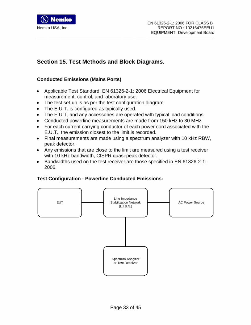
Section 15. Test Methods and Block Diagrams.
Conducted Emissions (Mains Ports) Applicable Test Standard: EN 61326-2-1: 2006 Electrical Equipment for
measurement, control, and laboratory use. The test set-up is as per the test configuration diagram. The E.U.T. is configured as typically used. The E.U.T. and any accessories are operated with typical load conditions. Conducted powerline measurements are made from 150 kHz to 30 MHz. For each current carrying conductor of each power cord associated with the
E.U.T., the emission closest to the limit is recorded. Final measurements are made using a spectrum analyzer with 10 kHz RBW,
peak detector. Any emissions that are close to the limit are measured using a test receiver
with 10 kHz bandwidth, CISPR quasi-peak detector. Bandwidths used on the test receiver are those specified in EN 61326-2-1:
2006. Test Configuration - Powerline Conducted Emissions:
EUTLine Impedance
Stabilization Network(L.I.S.N.)
Spectrum Analyzeror Test Receiver
AC Power Source

EN 61326-2-1: 2006 FOR CLASS B Nemko USA, Inc. REPORT NO.: 10216476EEU1
EQUIPMENT: Development Board ______________________________________________________________________________________
Page 34 of 45
Conducted Emissions (Telecommunication Ports) Test Method: Applicable Test Standard: EN 61326-2-1: 2006 Electrical Equipment for
measurement, control, and laboratory use. The test set-up is as per the test configuration diagram and as further defined
in EN61326: 2006. The E.U.T. is configured as typically used. The E.U.T. and any accessories are operated with typical load conditions.
LAN cable measurements may be taken with a LAN utilization in excess of 10%.
For each telecommunication port, conducted current and/or voltage measurements are made from 150 kHz to 30 MHz.
Measurements are taken with peak, quasi-peak, and/or average detectors. Quasi-peak and/or average detector measurements take precedence over peak detector measurements.
Detector bandwidths are those specified in EN 61326-2-1: 2006. Test Configuration:
EUT
Coupling/DecouplingNetwork(CDN)
orCapacitive Voltage Probe
or50 ohm resistor
Spectrum Analyzeror Test Receiver
Auxillary Equipment
Ferrites(If applicable)
Probe(If applicable)

EN 61326-2-1: 2006 FOR CLASS B Nemko USA, Inc. REPORT NO.: 10216476EEU1
EQUIPMENT: Development Board ______________________________________________________________________________________
Page 35 of 45
Radiated Emissions Test Method - Radiated Emissions: Applicable Test Standard: EN 61326-2-1: 2006 Electrical Equipment for
measurement, control, and laboratory use. The test set-up in the shielded room is as per the test configuration diagram. The E.U.T. is configured as typically used. The E.U.T. and any accessories are operated with typical load conditions. Radiated emissions measurements are made from 30 MHz to 1000 MHz.
Frequencies were initially identified in a semi-anechoic chamber. Amplitude measurements were made in a semi-anechoic chamber.
Variations in antenna height, antenna polarization, and E.U.T. azimuth are explored to produce the emission that has the highest amplitude relative to the limit.
If less than six emissions are better than 20 dB below limit, the noise level of the measuring instrument at representative frequencies is also reported.
Any emissions above 1 GHz are measured using a horn antenna and low noise pre-amplifier.

EN 61326-2-1: 2006 FOR CLASS B Nemko USA, Inc. REPORT NO.: 10216476EEU1
EQUIPMENT: Development Board ______________________________________________________________________________________
Page 36 of 45
Test Configuration - Radiated Emissions: Radiated Pre-scan:
SPECTRUM ANALYZERAND PLOTTER OR TEST
RECEIVER
COMPUTER
ANTENNA
E.U.T.
SHIELDED ROOM
Semi-Anechoic Chamber

EN 61326-2-1: 2006 FOR CLASS B Nemko USA, Inc. REPORT NO.: 10216476EEU1
EQUIPMENT: Development Board ______________________________________________________________________________________
Page 37 of 45
Electrostatic Discharge Test Method - Electrostatic Discharge: Applicable Test Method: EN61000-4-2: 2001. The test set-up is as per the test configuration diagram. The electrostatic discharge has been applied to all points and surfaces which
are accessible to personnel during normal usage of the E.U.T. (refer to test data table for a listing).
The generator is re-triggered for a new single discharge. This procedure is repeated ten times in each polarity for each point. The E.U.T. is exercised during testing. Test Configuration - Electrostatic Discharge:
ESD GUNINSULATINGSUPPORT
0.8m
VCP
470kohm
0.1m 0.5 x 0.5m1.6 x 0.8m
HCP
2m
The reference ground plane size projects beyond the horizontal coupling plane by at least 0.5 mon all sides.
0.1mperipheral equipment
E.U.T.
HCP - Horizontal Coupling Plane VCP - Vertical Coupling Plane
RGP
RGP - Reference Ground Plane

EN 61326-2-1: 2006 FOR CLASS B Nemko USA, Inc. REPORT NO.: 10216476EEU1
EQUIPMENT: Development Board ______________________________________________________________________________________
Page 38 of 45
Radiated Electromagnetic Field (Shielded Chamber) Test Method - Radiated Electromagnetic Field (Shielded Chamber): Applicable Test Method: EN61000-4-3: 2002. The E.U.T. is placed in the center of the Shielded Chamber and connected to
power and signal leads. The test set-up is as per the test configuration diagram. The frequency range is swept from 80 to 1000 MHz & 1400 to 2700MHz.. The modulation is 80% AM with a 1 kHz sinewave. The sweep rate is 1.5 x 10⁻³ decades second or slower. The step size is 1% of previous frequency (i.e. previous frequency * 1.01). The antenna is rotated in order to test both horizontal and vertical
polarization. The E.U.T is exercised during testing. Test Configuration - Radiated Electromagnetic Immunity (Shielded Chamber)
Signal Generator Video MonitorBroadband Amplifiers
(Optional)
E.U.T.
Test Distance
Biconilog Antenna 26 MHz - 1 GHz
Video Camera
240 VACvia L.I.S.N.
Shielded Enclosure
Fibre Optic Cable
Horn Antenna 1.4GHz to 2.7GHz
EUT Power
Shielded Chamber

EN 61326-2-1: 2006 FOR CLASS B Nemko USA, Inc. REPORT NO.: 10216476EEU1
EQUIPMENT: Development Board ______________________________________________________________________________________
Page 39 of 45
Electrical Fast Transient/Burst/Surge Test Method - Electrical Fast Transient/Burst/Surge: Applicable Test Method: EN61000-4-4: 2004 and EN61000-4-5: 2006. The E.U.T. is configured as shown in the test configuration diagram. The waveform is verified before testing commenced. Test Configuration – Electrical Fast Transient/Burst/Surge:

EN 61326-2-1: 2006 FOR CLASS B Nemko USA, Inc. REPORT NO.: 10216476EEU1
EQUIPMENT: Development Board ______________________________________________________________________________________
Page 40 of 45
R.F. Common Mode (A.M) Test Method - R.F. Common Mode (A.M.): Applicable Test Method: EN61000-4-6: 2003. The E.U.T. is configured as shown in the test configuration diagram. The frequency range is swept from 150 kHz to 80 MHz. The disturbance signal is 80% amplitude modulated with a 1 kHz sine wave. The rate of sweep is 1.5 x 10⁻³ decades per second or slower. The frequency is incremented at 1% of the start and thereafter 1 % of the
preceding frequency value. Test Configuration - R.F. Common Mode (A.M.): Setting Immunity Levels:

EN 61326-2-1: 2006 FOR CLASS B Nemko USA, Inc. REPORT NO.: 10216476EEU1
EQUIPMENT: Development Board ______________________________________________________________________________________
Page 41 of 45
Magnetic Immunity Test Method - Magnetic Immunity: Applicable Test Method: (EN 61000-4-8: 2000). The test set-up is as per the test configuration diagram. Power and other functional electrical quantities are applied to the E.U.T. Preliminary verification of equipment performance is carried out. The continuous magnetic field is applied at 50 Hz. Test Configuration - Magnetic Immunity:
AF Power Oscillator
Current Meter
Magnetic Loop
E.U.T.
Resistor
The current meter is used to calibrate the magnetic field
1.0 ohm
3 Foot Diameter

EN 61326-2-1: 2006 FOR CLASS B Nemko USA, Inc. REPORT NO.: 10216476EEU1
EQUIPMENT: Development Board ______________________________________________________________________________________
Page 42 of 45
Voltage Dips and Interruptions Test Method - Voltage Dips and Interruptions: Power to the E.U.T. is varied per the requirements specified in EN61000-4-
11: 2004. The E.U.T. is monitored for normal operation. Test Configuration – Voltage Dips and Interruptions Tests:
E.U.T.Universal
Power Supply500Iix
Computer
RS232
Power ToE.U.T.
North American3 Phase Power Input60 Hz

EN 61326-2-1: 2006 FOR CLASS B Nemko USA, Inc. REPORT NO.: 10216476EEU1
EQUIPMENT: Development Board ______________________________________________________________________________________
Page 43 of 45
Harmonics Test Method – Harmonics: Applicable Test Method: EN 61000-3-2:2006. The E.U.T. is configured as shown in the test configuration diagram. Test Configuration – Harmonics:
E.U.T.
Flicker / HarmonicsProcessorPACS-1
Universal Power Supply500Iix
Personal Computer
Printer
North American3 Phase Power Input60 Hz
240 VAC50 Hz
RS232
Data Bus

EN 61326-2-1: 2006 FOR CLASS B Nemko USA, Inc. REPORT NO.: 10216476EEU1
EQUIPMENT: Development Board ______________________________________________________________________________________
Page 44 of 45
Flicker Test Method – Flicker Applicable Test Method: EN 61000-3-3:2008 The E.U.T. is configured as shown in the test configuration diagram. The equipment is exercised for not less than 5 minutes and not more than 15
minutes. Test Configuration – Flicker:
E.U.T.
Flicker / HarmonicsProcessorPACS-1
Universal Power Supply500Iix
Personal Computer
Printer
North American3 Phase Power Input60 Hz
240 VAC50 Hz
RS232
Data Bus

EN 61326-2-1: 2006 FOR CLASS B Nemko USA, Inc. REPORT NO.: 10216476EEU1
EQUIPMENT: Development Board ______________________________________________________________________________________
Page 45 of 45
Section 16. Performance Criteria. Performance Criteria A: Normal operation of the EUT is expected. Please define:
Performance Criteria B: Degradation of product performance is allowed only during the application of the test. No change of stored data is alloPlease define:
Performance Criteria C: Temporary loss of function is allowed as long as the operator can restore proper operation after completion of the tesPlease define:
EUT operates normal.
EUT operates normal.
EUT has interuption in operation reset by the operator.