engineers’ guide to advancedtca microtca®2engineers’ guide to atca & microtca®...
TRANSCRIPT

www.eecatalog.com/atca
Engineers’ Guide to AdvancedTCA
®
& MicroTCA
®
Does Altera Have “Big Data” Communications on the Brain?
CompactPCI Serial is Ready to Go to Work
Intel Maintains its ATCA Foothold
Scan this QR code to subscribe
PICMG Picks Up Steam–All the Way to the Red Planet
Gold Sponsors

Make our expertise your solution - talk to us... we care.N.A.T. - Gesellschaft für Netzwerk- und Automatisierungs-Technologie mbHKonrad-Zuse-Platz 9 I 53227 Bonn I Germany I Fon: +49 228 965 864 0 I Fax: +49 228 965 864 [email protected] I www.nateurope.com I innovation in communication
Key features· 110-265VAC input (auto-range)
· protection circuit
· power factor correction
· on/off switch
· hold-up circuit
power conversion
· optical load indicator
· power management for 16 power channels
· backup power for other PMs (SMP)
· support for N+1 and 2+2
The NEW AC-Power Module – NAT-PM-AC600
The power of your MTCA system


Engineers’ Guide to ATCA® & MicroTCA® Technologies 20132
Welcome to the 2013 Engineers’ Guide to ATCA® & MicroTCA® Technologies
PICMG President Joe Pavlat summed up the theme for this issue when he recounted a presentation by Verizon’s CTO at the 2012 ATCA Summit, which stated that 60 percent of all telecom traffic is driven by video on smartphones—and this is expected to climb to a whopping 80 percent by 2015. Pavlat remarked, “They need a 60-fold increase in total network bandwidth within 10 years to hope to pull this off.” In an in-depth inter-view with Editor-in-Chief Chris Ciufo, Pavlat addresses the frenetic pace of PICMG standards evolutions over the last twelve months, driven by this insatiable need for bandwidth.
Ciufo also looks at Altera’s recent series of acquisitions, partnerships and announcements to explore the question: “Does Altera Have “Big Data” Communications on the Brain?” As counterpoint, Xilinx discusses how FPGAs support optical interconnects in next-gen 100G line cards in” Scaling 100G Wired Applications with Heterogeneous 3D FPGAs.”
And there’s more from our industry experts.
Kontron takes us deep into the two-year-old CompactPCI Serial specifi-cation for higher signal density and faster transmission frequencies in “CompactPCI Serial is Ready to Go to Work.” PMC addresses the ongoing customer demands for data center solutions that maximize I/O capa-bility in less space in “PCI Express Gen3 Enables Smaller, Faster Server Storage.” And Adax ties up the loose ends in a viewpoint on how the right security gateway technology can keep operators, customer devices and data secure, while opening up opportunities to relieve pressure on the core network in “The Weak Link in Mobile Security.”
Finally, our roundtable discussion pulls all of this together, with insights into the state of 40G and 100G Ethernet, Intel challengers in the data center and more. There’s even more great content on the web at www.eecatalog.com/atca, so come back often for news, in-depth technical articles, datasheets, white papers and videos. Hope to see you there.
Cheryl Berglund CoupéManaging Editor, EECatalog.com
Engineers’ Guide to ATCA® & MicroTCA® Technologies 2013www.eecatalog.com/atca
Vice President & PublisherClair Bright [email protected](415) 255-0390 ext. 15
EditorialEditor-in-ChiefChris A. Ciufo [email protected]
Managing EditorCheryl Coupé [email protected]
Vice President & Chief Content OfficerJohn Blyler [email protected](503) 614-1082
Creative/ProductionProduction Manager Spryte Heithecker
Graphic DesignersNicky Jacobson Senior DesignerJacob Ewing
Media Coordinator Jenn Burkhardt
Senior Web DeveloperMariam Moattari
Advertising/Reprint SalesVice President & Publisher Embedded Electronics Media GroupClair Bright [email protected](415) 255-0390 ext. 15
Sales ManagerMichael [email protected] (415) 255-0390 ext. 17
Marketing/CirculationJenna Johnson
To Subscribewww.eecatalog.com/subscribe
Extension Media, LLCCorporate OfficePresident and PublisherVince [email protected]
Vice President & Publisher Embedded Electronics Media GroupClair [email protected]
Vice President, Business DevelopmentMelissa [email protected]
Special Thanks to Our Sponsors
The Engineers’ Guide to ATCA® & MicroTCA® Technologies 2013 is published by Extension Media LLC. Extension Media makes no warranty for the use of its products and assumes no responsibility for any errors which may appear in this Catalog nor does it make a commitment to update the information contained herein. Engineers’ Guide to ATCA® & MicroTCA® 2013 is Copyright ®2013 Extension Media LLC. No information in this Catalog may be reproduced without expressed written permission from Extension Media @ 1786 18th Street, San Francisco, CA 94107-2343. All registered trademarks and trademarks included in this Catalog are held by their respective companies. Every attempt was made to include all trademarks and registered trademarks where indicated by their companies.


Engineers’ Guide to ATCA® & MicroTCA® Technologies 20134
ContentsPICMG Picks Up Steam—All the Way to the Red Planet
By Chris A. Ciufo, Editor-in-Chief ............................................................................................................................................................... 6
ATCA Reference Systems—The Netarium Series [Advertorial]By Advantech ........................................................................................................................................................................................... 10
Configurable ATCA Systems [Advertorial]By Advantech ........................................................................................................................................................................................... 11
Leading the Way with 40G ATCA Blade Innovation [Advertorial]By Advantech ........................................................................................................................................................................................... 12
Processor AMCs—Application Blades on a 40G Switch [Advertorial]By Advantech ........................................................................................................................................................................................... 13
FMMs Bring Unprecedented Flexibility [Advertorial]By Advantech ........................................................................................................................................................................................... 14
Enabling Superior ATCA System Throughput [Advertorial]By Advantech ........................................................................................................................................................................................... 15
Does Altera Have “Big Data” Communications on the Brain?By Chris A. Ciufo, Editor-in-Chief ............................................................................................................................................................. 16
CompactPCI Serial is Ready to Go to WorkBy Peter Ahne, Kontron ........................................................................................................................................................................... 17
Intel Maintains its ATCA FootholdBy Cheryl Coupe, Managing Editor .......................................................................................................................................................... 20
PCI Express Gen3 Enables Smaller, Faster Server StorageBy Juergen Frick, PMC ............................................................................................................................................................................. 22
Scaling 100G Wired Applications with Heterogeneous 3D FPGAsBy Ehab Mohsen, Xilinx ........................................................................................................................................................................... 25
The Weak Link in Mobile SecurityBy Drew Sproul, Adax ..............................................................................................................................................................................39
Product Services
Hardware
BladesAdax Inc.Adax PacketRunner Intelligent ATCA Carrier Blades ............................................ 29
Advantech Co., Ltd. ATCA-7310 Dual Cavium OCTEON CN6880 ATCA Blade with 40G Switch .......................................................................... 30DSPA-8901 AdvancedTCA DSP Blade .................................. 31 MIC-5333 Dual Intel® Xeon® E5 Series ATCA Blade with Dual-Dual 40G Fabric Support ............................................ 31
Emerson Network Power Centellis™ Series ATCA® Systems ...................................... 32 ATCA-7470 Dual Intel® Xeon® Processor-based 40G ATCA® packet processing blade ....................................................... 32
Scan Engineering Telecom GmbHSAMC-404 High-performance DSP board ............................. 33SAMC-514 Quad-core Processor AMC based on Core i7 ..... 34
Boards / Board Accessories Advantech Co., Ltd. AMC-4201/4202 Advanced Mezzanine Card Freescale QorIQ P4080 / P5020 AMC ............................................................. 35
Integrated PlatformsAdax Inc.Application Ready Platform Highly Integrated Platform Ready for Your Value-Add Application ............................................................................ 36
Scan Engineering Telecom GmbHSAMC-713 High Performance Virtex-6 AMC with FMC expansion site ....................................................................... 37
Test and AnalysisTeledyne LeCroyTeledyne LeCroy’s PCI Express® Protocol Analysis and Test Tools ...................................................................................... 38

REGISTERIT’S COMPLIMENTARY!
AND MORE AWESOME THAN WORK!
RTECC.COM
COME TORTECC
REAL-TIME AND EMBEDDEDCOMPUTING CONFERENCEWWW.RTECC.COM
TAKE A DAY TO LEARN ABOUT THE NEWEST IDEAS IN THE EMBEDDED INDUSTRY.CHECK OUT THE LATEST DEMOS.LISTEN TO TALKS FROM THE EXPERTS.
GET OUT OF YOUR OFFICE. RETURN WITH INSIGHT ABOUT THE FUTURE OF THE INDUSTRY.
BEDDENNN ABOUTIDEAS IN TDED IN
TAKE A DAAYYYYYYYYYY TO LEARRN AABBOTHE NEWESSSST IIDDDDDDDDDDDDDDEAEMBEDDED
W

Engineers’ Guide to ATCA® & MicroTCA® Technologies 20136
SPECIAL FEATURE
In the embedded space there are three primary
open standards organizations: PC/104 Con-
sortium, VITA and PICMG. Of the three,
PICMG has perhaps had the most activity
over the past twelve months since it’s so
closely tied to the commercial market’s tech-
nology whims and endless product introductions.
There have been updates to COM Express, CompactPCI,
AdvancedTCA (it’s now officially ok to call it “ATCA”)
and MicroTCA. An interview with PICMG’s president and
chairman—and my personal friend—Joe Pavlat reveals the
details going on in three major spec areas.
Going Back 20 YearsPICMG began in 1994 and continues to evolve with tech-
nology trends. In the last year alone, the IEEE has finished
off the 40G Ethernet spec, Intel has refreshed the Atom
product line to the Silvermont architecture and won SoC
smartphone designs, Cisco now forecasts M2M node growth
on the same charts as smartphones and tablets, the move to
serial interfaces like PCIe Gen 2/3 continues unabated, USB
3.0 is commonplace, and board vendors keep introducing
newer, faster, denser versions of AMD- , ARM-, Freescale-
and Intel-based single board computers (SBCs). Hundreds
of companies participate in PICMG to stay
abreast of and exert some control over all
this change.
Says Pavlat: “Our membership started to
decline a bit after the 2008 financial collapse,
but PICMG is still profitable and we’re picking
up new members again.” Membership now
stands at about 200 companies, with some
of the biggest names in the tech world listed
on the PICMG website (http://picmg.org/
v2internal/membership.htm#memberlists).
The organization focuses on three core
technology areas, which the membership
continues to develop (Table 1): the smallest
form factor is COM Express; the middle
size is CompactPCI and now CompactPCI
Serial; and the largest is ATCA, MicroTCA,
Advanced Mezzanine Card (AMC), or what
PICMG calls collectively “xTCA.” Of all the tech trends, says
Pavlat, the move to serial interfaces is providing the most
change in PICMG’s specs.
COM Express Version 2.1Pavlat believes COM Express is “probably the second most
popular small form factor behind PC/104,” having dozens to
hundreds of vendors offering COM Express versions. There
are over 700 products listed on the PICMG Product Listings
section of the website (http://members.picmg.org/kshow-
case/view). When first created, COM Express took a much
different tack from PC/104: it sought to abstract all of the
nuances of high-speed signaling from the user. By putting the
CPU and chipset on the mezzanine (computer-on-module)
card, the end user “didn’t need to worry about high-speed
interfaces, trace impedances, buried vias or any of those
details,” says Pavlat. The COM vendor worried about that; all
the user need to do was design the baseboard to interface to
relays, serial lines or other system-level I/O.
Because COM Express users are not willing to pay for fea-
tures they don’t need, the PICMG spec COM.0 defines seven
different pin-out types. Type 1 and Type 10 modules have a
single 220-pin connector (A-B), whereas Types 2 through 6
Table 1: PICMG’s three core form factor categories.
PICMG Picks Up Steam—All the Way to the Red Planet PICMG President and Chairman Joe Pavlat describes PICMG evolutions from small to large, including COM Express, CompactPCI, AdvancedTCA and MicroTCA.
By Chris A. Ciufo, Editor-in-Chief
In th
op
so
PI
ov
clos
nology
Th h b

www.eecatalog.com/atca 7
SPECIAL FEATURE
use a pair of 220 pin connectors (A-B, C-D) for a total of 440
pins. The details are shown in Table 2, taken from the COM.0
PICMG specification. For the sharp-eyed reader, Types 7-9 are
reserved for the future. COM Express boards can also come
in various sizes called Mini, Compact, Basic and Extended.
Table 2 also shows the market trend from parallel interfaces
to serial ones, and PICMG felt the need to revise the COM
Express specification COM.0 (1995) to Version 2.1 in May
2012. According to Pavlat: “There were about 15 compa-
nies actively participating in defining the serial interfaces
and modifications to COM Express. Of note were ADLINK,
Radisys, Kontron, Congatec, PFU Systems and GE Intelligent
Platforms, though there were others.” The changes made to
COM Express are too numerous to list here, but the design
trend towards rich multimedia and high-res video interfaces
played a strong role in the redesign. There’s now extensive
video port support for VGA, LVDS, SDVO, DP, eDP, DVI and
HDMI terminal drivers plus a x16 PCI Express Graphics
(PEG) port to carrier board graphics controller.
The changes include: migrating AC97 audio to high-definition
audio; the SDVO interface is no longer muxed with the PEG
port but available now via a digital display interface port in
Types 6 and 10; there are more PCIe lanes added throughout;
rarely used 12V pins were “reclaimed” for new serial func-
tions; IDE and PCI ports were dropped or diminished for
PCIe and SATA; and LVDS ports were added, some of which
share pins with optional CAN bus signals.
All in all, a comprehensive update of the original 1995 spec
was performed to evolve COM Express with the changes in
serial interfaces, IC vendor chipsets and end user require-
ments. It’s interesting to note what COM Express doesn’t
do. According to PICMG’s Pavlat: “Unlike VME, which inten-
tionally maintains backward compatibility because of its
customer base requirements, it doesn’t always make sense for
COM Express to be backward-compatible.” The market wants
forward momentum, and PICMG is delivering it with major
changes to the COM Express specification to Version 2.1.
As well, PICMG members are in the process of overhauling the
“COM Express Carrier Design Guide,” a textbook-like docu-
ment describing how best to build a baseboard. Released in
2009 as Revision1, a new version is due out soon to map the
I/O changes brought about in Version 2.1 of COM.0 (Figure 1).
CompactPCI Goes Serial and ExpressEthernet just goes faster and faster. From 10Mbps up to
40Gbps, we’ve been discussing the “serialization” of Ethernet
applied to COM Express. But it was on an open standard Com-
pactPCI variant called PICMG 2.16 that in 2000 facilitated the
first switched backplane using
plain vanilla Ethernet. It was
released during the so-called
“fabric wars” when, according
to Pavlat, “Ethernet was number
one then, it’s number one now,
and it just keeps getting faster
and faster.”
The original CompactPCI spec
is nearly twenty years old,
was released in 1995, used the
then-new parallel PCI bus,
and was based on the familiar
(and well-accepted) 3U/6U
Eurocard standard. Unlike its
quasi-competitor VME which
is also based on the Eurocard,
it wasn’t aimed at the military
market and was “much cheaper
than VME.” Successful in
commercial markets galore, “cPCI”—as it is sometimes
called—actually did find its way into mil/aero/defense/space
applications because the 3U size meshed perfectly in smaller
1/2 ATR( short) avionics boxes and had ample I/O on the
multi-row connector.
According to PICMG’s Pavlat, the newest Mars Rover Curi-
osity is controlled by CompactPCI (http://members.picmg.
org/apps/group_public/document.php?document_id=6418).
The two Rover Computational Element (RCE) cards are
radiation-hardened PowerPC 3U cPCI modules built by BAE.
Pavlat says that BAE claims that about 70 percent of satellite
missions today use CompactPCI.
Table 2: COM Express pin-out types. Type 1 is the least functional with the smallest amount of I/O. (Courtesy: PICMG COM.0 specification.)
Figure 1: PICMG’s COM Express Carrier Design Guide is due for a refresh soon because of all the changes in the COM Express spec that added higher speed serial interfaces. (Courtesy: PIGMG).(http://www.picmg.org/pdf/PICMG_COMDG_100b.pdfhttp:/www.picmg.org/pdf/PICMG_COMDG_100b.pdf)

Engineers’ Guide to ATCA® & MicroTCA® Technologies 20138
SPECIAL FEATURE
PCI Express was added to CompactPCI
in 2005, but driven by National Instru-
ments, a Revision 2 version of the
CompactPCI Express specification was
released in April 2013. The new spec
quadruples the bandwidth to 5 Gbps
transfer rate and 8 Gbps transfer on
PCIe. Interface- and product-level
interoperability was given careful
consideration because unlike the COM
Express market, instrumentation
customers do care about backward
compatibility and maintaining legacy
systems. Besides performance improve-
ments, Rev 2 clears the way for modern
revisions and I/O updates to the
(non-PICMG) complementary test and
instrumentation specification called
PXI. CompactPCI Express Rev 2 “has
parallel interfaces, like the old Com-
pactPCI, some serial interfaces like the newer CompactPCI
Serial, but extra pins and functions for instrumentation
users like clocks and triggers,” says Pavlat.
In Europe, MEN MikroElektronik pushed forward a new
specification called CompactPCI Serial in 2011 which
replaces parallel interfaces with high-speed serial: SATA,
PCI Express and Ethernet on the backplane. Driven by
MEN’s customers in the transportation and industrial con-
trol markets, “It really gives CompactPCI a mid-life kicker,”
says Pavlat, “and depending upon how you build the back-
plane, you can use old CompactPCI cards as peripherals if
you want, or build the system entirely out of CompactPCI
Serial cards.”
All totaled, says Pavlat and a press release (http://picmg.org/
officersadmin/NewsPDFs/CompactPCI%20Express%20Enhance-
ments%20-%20PICMG%20PR.pdf) issued by PICMG in April
2013, the market for all things CompactPCI “represents well
over $400 million in annual revenues,” making CompactPCI
one of PICMG’s most successful specifications.
AdvancedTCA: HA and Hot Swap Spawn MicroTCAPICMG’s third major specification series is xTCA which
includes AdvancedTCA (ATCA), Advanced Mezzanine Card
(AMC) and MicroTCA. The AdvancedTCA market, according
to Pavlat, is somewhere between $1.5B-2.5B per year, pri-
marily driven by the telcos in applications ranging from
central office switches to cellular base station back haul
equipment. Conceived in 2001 by a collection of telco compa-
nies looking to focus on their software IP instead of building
proprietary hardware that added no value, “ATCA is our most
successful specification to date,” says Pavlat, “because it had
the most direct customer input. It’s been a huge success.” The
requirements documents that drove ATCA came from com-
panies such as Alcatel, Lucent, Nortel, Motorola and more.
Technically, the most important feature of ATCA is the
high-availability, managed architecture that makes sure if
something fails, another entity takes over. In fact, the exten-
sive infrastructure—enabled by infrastructure standards
such as IPMI—monitors fan speeds, voltages, currents, tem-
peratures and is capable of predicting the failure of a fan, for
example, weeks before it fails. “With over 30 years of mostly
proprietary HA experience,” asserts Pavlat, “the telcos knew
what they wanted and needed...” Part of that architecture
required a bladed architecture that could evolve with changing
processor standards such as Intel Xeons and packet proces-
sors, but also included a hot-swappable, HA mezzanine card
with I/O tailored to each system requirement.
The result was the Advanced Mezzanine Card (AMC), which
spawned its own card standard called PICMG MicroTCA (or
μTCA for short).Ratified in 2006, the specification MTCA.0
is going on eight years old and has itself spawned four sub-
sidiary specifications (Table 3). Small and compact, AMC
cards plug into a backplane that forms an HA, hot-swappable
system “ that gets close to the two-level maintenance holy
grail in military and defense applications,” chuckles Pavlat.
Like the story in 3U CompactPCI, the military was searching
for a lower-cost alternative to the very rugged ANSI VITA 1
(VME) specification. The first version MTCA.1 in 2009 was a
“slightly rugged” air-cooled version. But driven by companies
such as BAE and Emerson Network Products, the hardened,
conduction-cooled MTCA.3 was released in 2011.”The con-
nectors, wedgelocks and other mechanicals were either
influenced by or taken directly from lessons learned on VME
and VPX,” says Pavlat. The multiyear effort was “extremely
well-thought-out, extremely well-tested and was followed by
an air-cooled version which was only ratified last month in
April 2013,” says PICMG’s Pavlat. [At the time of my inter-
view with Pavlat in May, MTCA.2 “Hardened Air-Cooled
MicroTCA” had not yet been announced. Ed.]
Figure 2: JPL’s Mars Rover Curiosity uses dual CompactPCI boards designed by BAE Systems. (Courtesy: PICMG, NASA, and JPL.)

www.eecatalog.com/atca 9
SPECIAL FEATURE
more remote management capabilities,
among other things.
Not content to rest on their heels, PICMG
members will later in 2013 be defining
ATCA extensions and enhancements that
will “describe how to build double-width
modules, increase power from 400W to
800W and eventually put hundreds of
gigabits of cheap DIMM memory in the
double-board sandwich,” asserts Pavlat.
In effect, this should make ATCA more
attractive to the high-end server market
by alleviating the need for more costly,
45-degree low profile DIMMS used in single
high (1.2-inch pitch) ATCA boards.
Bandwidth: It’s What’s for DinnerAs my time with Joe ran short, I asked him
to summarize the frenetic pace of PICMG
over the last twelve months. “It’s the
insatiable need for bandwidth in what I
believe is the largest, or one of the largest,
markets on earth. We’ve gotten to 40Gbps
on copper and I’m pretty confident we’ll
get to 100Gbps before long,” he muses. But
he sees the day coming when copper will “run out of gas” and
PICMG will need to add optical on the backplane. Reflecting
back on the plethora of specs PICMG has launched in the last
year, I wonder how many of those will eventually need to be
revised one more time...just to add fiber.
It’s certainly exciting. These high-end HA features found on
all of PICMC’s initiatives will eventually move down into
embedded and ultimately into consumer electronics, which is
perhaps the biggest global market of all. Summarizes PICMG’s
Pavlat: “I’m a convert towards cheap electronics running high
availability. It’s the new paradigm.”
Chris A. Ciufo is editor-in-chief for embedded content
at Extension Media, which includes the EECatalog
print and digital publications and website, Embed-
ded Intel Solutions, and other related blogs and
embedded channels. He has 29 years of embedded
technology experience, and has degrees in electrical
engineering, and in materials science, emphasizing solid state phys-
ics. He can be reached at [email protected].
Joe Pavlat has been president and chairman of the PCI Industrial
Computer Manufacturers Group (PICMG) since 1995 and was di-
rectly involved in the development of both the CompactPCI® and
AdvancedTCA® standards.
Rounding out the MicroTCA family is MTCA.4 aimed at the
niche market for high-energy physics data acquisition in
places such as CERN searching for the Higgs boson particle.
MicroTCA Enhancements for Rear I/O and Precision Timing
brings the high availability of MicroTCA to the thousands of
detectors used in particle physics experiments. When there’s
an uncertainty on the order of Avogadro’s number of creating
or detecting a particle, scientists want the electronics to work
reliably and keep on working should something fail, without
having to power down the accelerator. It turns out that the
original high-availability goal of ATCA is finding greater trac-
tion in many niche markets, from military to instrumentation
and control.
And what of ATCA itself? Pavlat recounts a presentation by
Verizon’s CTO at the 2012 ATCA Summit which stated 60
percent of all telecom traffic is video driven by smartphones,
expected to climb to a whopping 80 percent by 2015. “They
need a 60-fold increase in total network bandwidth within 10
years to hope to pull this off,” remarks Pavlat. ATCA reached
a major milestone in 2012 when the standard for 40Gbps Eth-
ernet was released.
“ATCA has been 10Gbps/channel Ethernet since the very
beginning,” says Pavlat. “PICMG 3.1 R2 quadruples the band-
width of a single chassis. A full mesh chassis can handle 10
Terabits/s of data across 256 channels!” This rate is exception-
ally important for the telecom industry given the constraints
of size, power and legacy rack space traded off against the
industry’s bandwidth forecast. Other updates during 2012
include the introduction of Hardware Platform Management
HPM.2 (LAN-Attached IPM Controller) and HPM.3 (DHCP-
Assigned Platform Management Parameters), which enable
Table 3: MicroTCA, a rugged offshoot of PICMG’s Advanced Mezzanine Cards, has multiple specifications. The appeal of MicroTCA is the high-availability, hot-swappable compact archi-tecture and backplane. (Courtesy: PICMG.)

ATCA Reference Systems -
The Netarium Series
Systems OverviewAdvantech’s Netarium™ series of ATCA reference systems
are specifically targeted to help network equipment providers
reach superior levels of performance over traditional rackmount
servers or appliances and extend their product range at the
high end. The series represents a new generation of systems
which offer superior performance, scalability and flexibility with
the latest 40 Gigabit Ethernet (40G) backplanes, switches and
application blades. We optimize the systems to achieve the
highest possible density at the rack level, with a maximum
number of payload blades, network ports and switching
capacity.
Each system is tailored for customers to rapidly deploy in data
communication markets for applications which require faster
and deeper packet processing such as policy and charging
enforcement, network security, real-time traffic monitoring, load
balancing, subscriber analytics and content optimization among
others. As ATCA was designed to meet the carrier-grade
constraints of the telecom industry, the systems integrate the
chassis, cooling, power distribution and shelf management into
an off-the-shelf platform solution capable of superior 5 NINES
availability and reliability.
High Performance SystemsRising volumes of data traffic, media-rich applications and
data center consolidation are driving the need for increased
bandwidth scalability and high-speed connections. To meet
these challenges, Advantech’s flagship Netarium-14 targets the
high-end market where equipment providers require superior
performance, scalability and deployment flexibility for their
large enterprise, managed security service provider or carrier
customers.
Mid Range RequirementsNetarium-6 focuses on the high performance needs of large
enterprise customers with a cost effective system loaded with
four MIC-5333 dual Intel® Xeon® E5-2600 blades and 40G
switches in a dual-star configuration. The system provides up
to 1.28 Tbps switching capacity and each MIC-5333 blade
with RTM can accommodate up to 4 FMMs for over 100Gbps
egress per blade with high-speed encryption using FMM-based
acceleration modules. The system is an ideal platform for cloud-
based security services in private or data center clouds.
Entry-Level FlexibilityNetarium-2 is the ultimate in entry level flexibility. This 2-slot
platform allows OEMs to redeploy common platform hardware
which scales when needed. Based on the MIC-5333 it packs
more processing power than previous generation 6-slot
systems. With an increase in miniaturization and performance
at the blade level it is accompanied by a new concept at the
mezzanine level to bring more I/O and acceleration closer to the
processing cores. With four FMM sites on each ATCA blade and
RTM, the MIC-5333 offers the broadest flexibility in entry level
system performance on ATCA.
Netarium™-14 14-SLOT, 19 ” wide 13U high
AdvancedTCA Shelf fully integrated
Up to 12 MIC-5333 or MIC-5332
Dual Intel® Xeon® blades
Dual-Star backplane with 40G
Switches for non- blocking base and
fabric switching
300W+ per slot power distribution
and cooling capability
Netarium™-6 6-SLOT 19” wide, 6U high,
AdvancedTCA Shelf fully integrated
4 MIC-5332 or MIC-5333 Dual
Intel® Xeon® blades
Dual-Star backplane with 40G
Switches for non-blocking base and
fabric switching
300W+ per slot power distribution
and cooling capability.
192 Intel® Xeon® E5-2600 Cores
1.28 Tbps Switching Capacity
64 Intel® Xeon® E5-2600 Cores
1.28 Tbps Switching Capacity
Up to 32 Intel® Xeon® E5-2600 Cores
Up to 20 10GbE Ports
ATCA Systems
Netarium™-2 2-SLOT, 19” wide, 3U high,
AdvancedTCA Shelf fully integrated
with 2 MIC-5333 Dual Intel® Xeon®
blade and RTM-5104
64 Intel® Xeon® E5-26
1.28 Tbps Switching C
N
Up to 32 Intel® Xeon®
http://www.advantech.com/nc

Configurable ATCA Systems
Configuration FlexibilityWe know that each of our OEM customers is different which is
why we built out ATCA Systems Integration Team (SIT) to create
customized ATCA platforms and meet the application-specific
needs of network solution providers. The team is geared to
building fully tested, cost-optimized platform solutions utilizing
blade and platform technology from Advantech and integrating
it with 3rd party hardware and software. Advantech’s proven
expertise in developing ATCA platforms is made available
to equipment providers who need to outsource hardware
integration in order to focus R&D investment on application
value-add – or simply look at ATCA as an integrated networking
platform like a high end appliance.
Advantech SIT delivers fully integrated and certified platforms
which not only reduce your development time, but allow you to
allocate a larger percentage of R&D budget to vertical market
System Configuration ExamplesIntegrating powerful, high performance ATCA systems has its constraints and can be a complex and lengthy process that’s
not as simple as plug and play. ATCA requires many levels of expertise from platform software and hardware engineering,
system, reliability and availability engineering, and from compliance and regulatory specialists. The ATCA standard and pre-
established rules from PICMG along with their interoperability test suites certainly help to shorten the integration process, but
functional teams have to ensure that software and hardware integration starts very early in the system design cycle to ensure
timely and solid product rollout. With a multitude of component level permutations possible, each hardware payload needs
to be carefully defined and tested to ensure it can meet final application software needs. Depending on the final operating
environments, AC or DC powered systems may be required and shelf management software may be different.
The table below shows several examples of payloads which can be integrated into systems and configured to address many
leading industry applications. These examples reveal what is possible with Advantech ATCA systems and serve as a basis for
defining more precise application-specific solutions.
ATC
A S
ystem
s
value-added development. We work closely with a strong
global ecosystem of hardware and software vendors, including
chipset, board, chassis, operating system and middleware in
addition to our own product development. Ecosystem partners
are selected based upon project, technology, logistic and
geographic requirements and managed by the SIT team to
provide highly optimized customer-specific solutions.
Our SIT Team offers the broadest choice of multi-core products
for networking applications. With the ability to deliver x86,
NPU, DSP and Switching technologies developed in-house,
Advantech has full control over all the major building blocks
for system level design. These services allow our customers to
successfully face the challenges of converging networks and
increasing bandwidth demand through improved time to market
and a reduction of total cost of ownership as result of reduced
maintenance and test efforts.
2-slots
Application Blades
Media Gateway1 x MIC-5332 dual Intel® Xeon® blade
1 x DSPA-8901 DSP blades
Packet Generation &
Test
1 x MIC-5332 dual Intel® Xeon® blade
2 x ATCA-7310 NPU blades
Single-box EPC1 or 2 x MIC-5333 dual Intel® Xeon®
blades
6-slots
Application Blades
LTE Network Test
1 x MIC-5332 dual Intel® Xeon® blade
1 x DSPA-8901 DSP blade
2 x Customer I/O blades
Lawful Intercept Probe
2 x MIC-5333 dual Intel® Xeon®
blades
2 x ATCA-7310 NPU blades
Media Server
2 x MIC-5333 dual Intel® Xeon®
blades
2 x DSPA-8901 DSP blades
100Gbs UTM4 x MIC-5333 dual Intel® Xeon®
blades
14-slots
Application Blades
Video Transcoding 2 x MIC-5332 dual Intel® Xeon® blades
Up to 10 DSPA-8901 DSP blades
QoS / Policy Control8 x MIC-5333 dual Inte® Xeon® blades
4 x ATCA-7310 NPU blades
http://www.advantech.com/nc

ATCA Blades
The cornerstones of our ATCA product line are the blades
designed in our own labs and manufactured on our own
production lines. That way we manage the entire life cycle and
control all our costs to give customers the best service at the
right price. Our X86, NPU, DSP and switch blades are designed
in unison with the leading silicon suppliers to give you early
access to the very latest technology to accelerate your next
generation product design and give you first mover advantage.
Application and Networking BladesOur Intel® Xeon® blades are the application powerhouses. With
10 blades in 14-slots connected to four 40 Gigabit Ethernet
switches across a dual dual-star backplane you can’t get
faster network traffic in and out of an x86 blade. Today only
Advantech can provide 160 Gigabits per second of aggregated
bandwidth spread over four 40 Gigabit ports from a dual Intel®
Xeon® blade. What’s more, our MIC-5333 with its modular FMM
concept adds flexibility to personalize the blade with more I/O
ports, acceleration and offload. You can configure it precisely for
your application workload – so you get what you want and you
pay only for what you need.
Network Processor BladesOur NPU blade based on Cavium’s Octeon II processor
integrates application acceleration engines for DPI,
compression/decompression and new security standards such
as SNOW 3G. This makes it ideally suited for enterprise apps
and 4G networks.
DSP For Media ProcessingOur DSPA-8901with twenty C6678 DSPs provides 160 cores
of processing power to reach performance densities for the
highest capacity media gateways. It reduces system cost
and frees up slots in gateway elements for extra subscriber
capacity and throughput. It adds outstanding image processing
performance to solutions in Mobile, Web and IP TV markets.
40G SwitchingFinally, our ATCA-9112 40 Gigabit switch is the backplane
orchestra leader. Complemented by the T-HUB4 switch from
Telco systems and their BiNOX™ load balancing and carrier
class switch management suite, we offer high speed, managed
solutions with up to 640 Gigabits-per-second of switching
capacity per switch blade.
DSPA-8901 20 Texas Instruments C6678 DSPs
512MB/1GB DDR3 memory per DSP
BCM56321 10GbE switch for both Fabric
Interface and Base Interface
Freescale QorIQ™ P2020 for Local Management
Processor (LMP)
IDT Tsi577 Serial RapidIO switches
Leading the Way with 40G ATCA Blade InnovationAdvantech’s ATCA blades are designed in unison with the leading silicon suppliers
enabling OEMs with the earliest possible access to new technology.
MIC-5333 Two 8-Core Intel® Xeon® E5 Series processors
Future Intel® chipset code name Cave Creek
Eight DDR3 VLP DIMMs up to 256 GB with ECC
support
Up to four 40GBaseKR4 ports on FI to support
Dual-Dual Star Topology
Other fabric configurations supported via two
Fabric Mezzanine sites (type I)
Two 10/100/1000BASE-T front panel ports
One FMM (type II) for front IO or acceleration
Hot swappable RTM with 36 PCIe gen.3 lanes
ATCA-7310 Dual Cavium Octeon II CN6880 1.0 GHz with 32
MIPS™ II processor cores
Up to 64 GB DDR3 1066 MHz DIMMs; 32 GB
for each CN6880
40 GbE (KR4) and four 10 GbE (KR) FI with Dual
Star routing support
Eight 10GbE SFP+ and four 1GbE SFP Rear I/O
support
Switch management support on L2, QoS,
Multicast (SW options)
ATCA-9112 & T-HUB4 40GbE switch blade provides 10/40GbE
switching for 16 slots and eight 10GE uplinks
Fabric interface bandwidth up to 640Gbps
Separate base and fabric interface switching for
enhanced security and protection
BiNOX™ switch management suite
ATCA-9112 Adds a mid-size AMC site for host application
processing, acceleration or offload functions
MIC-5332 Two Intel® Xeon® E5-2600 Processors and Intel®
C600 Series PCH server class chipset
Eight DDR3 VLP DIMMs up to 256 GB with ECC
support
Up to four XAUI ports on Fabric interface and two
1000BASE-T ports on Base interface
One Fabric Mezzanine Module (FMM) support
with front I/O support (type II)
Two CFast / one 2.5” SSD storage device
M
M
A
A
A
http://www.advantech.com/nc

40G
Sw
itch a
nd
AM
Cs
ATCA-9112The ATCA-9112 switch blade provides 10/40GbE switching for
up to 16 slots and 8 front panel uplinks with a 640Gbps non-
blocking fabric switch from Broadcom.
Designed for network security, LTE and DPI-centric applications,
the ATCA-9112 offers the highest aggregate switching
bandwidth within an ATCA chassis enabling support for up to
16-slot systems. A Broadcom BCM56846 ensures seamless
integration through open standard hardware supporting
Processor AMCs – Application Blades on a 40G Switch
MIC-5603Intel® Xeon® 3rd Generation
Core-i7 AMC
AMC-4201Freescale QorIQ
P4080 AMC
AMC-4202Freescale QorIQ
P5020 AMC
40GbE or 10GbE ATCA node blades. A Broadcom BCM56321
provides ATCA base interface connectivity.
The switch offers a flexible approach to hub blade functionality
via a mid-size AMC site to host control plane, application
processing, acceleration or offload functions. Advantech’s
Freescale QorIQ™ P5020-based AMC-4202, P4080-based
AMC-4201 or x86-based MIC-5603 PrAMC can be used to
consolidate processing requirements.
Main Features 40GbE switch blade provides
10/40GbE switching for up to slots
10/40GE fabric interface with eight
10GE uplinks
Fabric interface bandwidth up to
640Gbps
Separate base and fabric interface
switching for enhanced security and
protection
Mid-size AMC site for host
application processing,
acceleration or offload functions
http://www.advantech.com/nc

Fabric Mezzanine Modules
Designing with Fabric Mezzanine ModulesThe FMM concept is one of the key elements in Advantech’s
Customized COTS (C2OTS) strategy. FMMs are a new
denominator for personalizing a common platform at the blade
level and they scale extremely well for both I/O and acceleration
functions. The MIC-5333 ATCA blade based on Intel® next
generation communications platform codename Crystal Forest
houses three FMM sites on the front blade and between one
and four FMM sites on the rear transition module enabling a
wide variety of solutions.
FMMs also facilitate fabric interface flexibility allowing equipment
providers to deploy the MIC-5333 into 40G or 10G topologies:
A double-sized FMM carrying four i82599’s provides two
fabric interfaces with four 10GBaseKR ports each.
For designers requiring 40GBaseKR4 interfaces, a Mellanox
CX-3 FMM supports two 40G ports enabling dual dual-star
backplane architectures with two FMM modules for four times
40Gbps in and out of the blade.
Finally a single i82599 FMM makes it possible to adapt MIC-
5333 with 10GbE in order to upgrade legacy systems in the
field.
The FMM specification defines the high speed interfaces and
associated FRU management. In addition the specification
supports a zone 2 connector interface for custom fabric
connectivity like SRIO. Signal integrity between FMMs and
the Fabric Interface on ATCA blades is ensured via a re-driver
between the zone 2 connector and the FMM. A FRU EEPROM
on the FMM describes its thermal & power requirements
and zone 2 interface information, while all other aspects are
managed by a BMC on the ATCA blade.
FMMs are compact, just 6.4 x 7.5 cm2s and use FMC
compliant connectors for high speed differential I/O. In fact,
there is adequate space to fit 40mm BGA ASICs and FPGAs
and associated components with a thermal budget < 20W.
The I/O area provides overhang for connector support on front
panels or rear transition modules (RTM) making FMMs a good fit
for specialized processing close to the application I/O.
With a common platform for workload consolidation like the
MIC- 5333, up to 4 FMM sites provide a wide choice of PCIe
I/O and acceleration:
MIC-5332 1 FMM to Front Panel
MIC-5333 3 FMMs (2 Fabric, 1 Front Panel)
RTM-5104 1 FMM to Rear Panel
For example, there are sufficient FMMs to turn the MIC-
5333 common platform into a 100G line card with crypto
acceleration.
By adopting an FMM approach for standard and custom
designs, OEMs can effectively redeploy them across form
factors scaling from appliances to ATCA systems for functions
such as:
Proprietary acceleration hardware
Specialized coding and transcoding algorithms
Signal & image processing
Military & commercial cryptography
FMMs Bring Unprecedented Flexibility
FMM-5001BIntel® 82599EB with
2 x 10GBaseKX4 FI
FMM-5001QQuad Intel® 82599ES
8 x 10GBaseKR FI
FMM-5004MMellanox CX3 with 2
x 40GBaseKR4 FI
FMM-5001FIntel® 82599ES for 2 x
10GbE with dual SFP+
FMM-5002Server Graphics Controller
with VGA connector
FMM-5006Intel® QuickAssist Accelerator
FMM-5006
http://www.advantech.com/nc

Fab
ric M
ezza
nin
e M
od
ule
s
For customers that invest in the Intel path to workload
consolidation, the FMM enables a common platform capable
of unprecedented throughput. System platform solutions which
may have been deployed across several blades are rapidly
being consolidated onto just one. Today, there’s more packet
processing power on our latest MIC-5333 ATCA blade, based
on the Intel® Xeon® E5-2600, than in a fully-loaded 6-slot
system of 5-years ago. Advantech is enabling customers in this
miniaturization process by introducing a breakaway technology
at the small mezzanine level in order to bring more I/O and
acceleration closer to the processing core and enable flexible
fabric connectivity to match increasing interconnect bandwidth
demands.
ATCA System TopologiesMost standard ATCA systems incorporate two switch blades.
Each of the node blades connects to each of the switch
blades. This places the switch blades at the center of a star
network connected to each of the node blades. The two switch
blades form two stars, hence the name “dual star”. For many
applications the improved packet and processing performance
offered by Advantech’s MIC-5332 and MIC-5333 node blades
starts to create the opportunity to leverage a new performance
paradigm. In the past the ATCA system bottleneck was
attributed to the iA-based node blades but now it’s shifting to
the switch blades. Advantech’s Intel® Xeon® E5-2600 –based
node blades are able to handle 40Gbps of traffic and more.
With ten blades in a system, applications requiring 400Gbps
of system throughput are constrained by the lack of switching
capacity in a dual-star ATCA topology. As state-of-the-art
switching silicon saturates at around 600Gbps, the ATCA
system’s switching capacity is limited to 1.2Tbps. For a
400Gbps system that means that packets can hop through the
switches a maximum of three times. As two hops are typically
consumed for ingress and egress traffic, three hops total
presents an important performance challenge. Fortunately, the
ATCA specification provides for the ability to use four switch
blades to create four fabric networks known as a dual dual-
star topology. Four times 600Gbps yields 2.4Tbps switching
capacity which allows an average of 6 hops for a packet in
a 400Gbps system. The challenge, though, is that the node
blades are now required to connect four network ports, one to
each hub blade.
Many x86 blades available today have been designed for
telecom networks with lower throughput rates, but datacom
customers need this higher throughput enabled by dual-dual
star topologies right now. To satisfy their needs Advantech has
built dual-dual star capabilities in to its MIC-5332 and MIC-5333
blades to support four backplane network ports via FMMs. The
MIC-5322 has one dual 10GbE controller down on the blade
supporting two 10GE ports to the backplane. An FMM-5001B
can be used to drive two additional 10GbE backplane ports. On
the MIC-5333, the backplane ports are connected to two FMM
sites allowing the widest choice of 10GbE or 40GbE dual-dual
star fabric interfaces available today.
FMMs are a new denominator for
personalizing a common platform at
the blade level. They scale extremely
well for both I/O and acceleration
functions. When coupled with the
workload consolidation capabilities of
the MIC-5333, they provide customers
with a wider choice of flexible and
scalable solutions for their next
generation platform designs.
Enabling Superior ATCA System ThroughputThe FMM has become an essential element in ATCA system design flexibility, enabling node
blade connectivity for 20, 40, 80 and 160Gbps connectivity to the backplane.
+
F
p
t
w
f
w
t
w
s
g
Learn more about ATCA
Toll Free: 1-888-576-9668
Email: [email protected]
http://www.advantech.com/nc

Engineers’ Guide to ATCA® & MicroTCA® Technologies 201316
SPECIAL FEATURE
I caught up with an old friend at April’s DESIGN West 2013
conference in San Jose: Chris Balough, senior director, product
marketing for SoC products at Altera. I knew Chris from when
he was at Triscend (purchased by Xilinx). Chris is now in
charge of Altera’s SoC products which are Arria V, Stratix V and
Cyclone FPGAs with ARM cores in them which compete with
Xilinx’s Zynq devices. Chris shed some light on some of these
announcements, but remained mum on what they all might
mean taken collectively. I think they add up to something big
in “Big Data.”
X before A? We’ll SeeSubconsciously I think of Xilinx first when the word “FPGA” is
flashed in front of me, but Altera’s the company pushing more
boundaries of late. Their rat-a-tat machine gun announce-
ments this year got my attention.
In the summer of 2012, I did an interview with Altera’s
senior vice president of R&D Brad Howe and he spread out
as much of the roadmap on the table as he could. Things like
HSA, OpenCL, and better gigabit transceivers were all on the
horizon. Shortly thereafter, Altera extended their relation-
ship with TSMC to 20nm for Arria and Cyclone FPGAs. Then in
early 2013, they rocked the industry by locking up an exclusive
FPGA relationship with Intel for the industry’s only produc-
tion 14nm tri-gate FinFETs.
Spring Cleaning ; Altera’s Getting Ready For…?Now in Spring 2013, Altera is making headlines like these:
FPGA Design in the Cloud–Try It, You’ll Like It, Says Plunify.
(See our February 2013 article with Plunify at http://eecatalog.
com/fpga/2013/02/06/practical-applications-of-cloud-com-
puting-in-semiconductor-chip-design/).
Altera and AppliedMicro will Cooperate on Joint Solutions for High
Growth Data Center Market.
Altera Expands OTN Solution Capabilities with Acquisition of TPACK.
Altera Stratix V GX FPGAs Achieve PCIe Gen3 Compliance and
Listing on PCI-SIG Integrators List.
Altera to Deliver Breakthrough Power Solutions for FPGAs with
Acquisition of Power Technology Innovator Enpirion.
My Take: Altera’s Move in Big DataAnalysts estimate that nearly 50 percent of the revenue in
FPGAs comes from high end, high density, costly FPGAs like
the Xilinx Vertex 7 and Altera Stratix V. Segments like wireless
and wireline packet processing, plus financial or image pro-
cessing algorithm processors increasingly rely on these kinds
of FPGAs in lieu of ASICs, GPGPUs, or proprietary network
processors. So every advantage in IP, process technology, or
partnership that Altera has, gets the company one step closer
to more design wins. We’ll see what Altera does with all of
these recent announcements.
Chris A. Ciufo is editor-in-chief for embedded
content at Extension Media, which includes the EE-
Catalog print and digital publications and website,
Embedded Intel® Solutions, and other related blogs
and embedded channels. He has 29 years of em-
bedded technology experience, and has degrees in
electrical engineering, and in materials science, emphasizing solid
state physics. He can be reached at [email protected].
Does Altera Have “Big Data” Communications on the Brain?In wireless, wireline and financial big-data applications, moving all those packets needs prodigious FPGA resources, not all of which Altera had before its recent series of acquisitions, partnerships and otherwise wheeling-and-dealing.
By Chris A. Ciufo, Editor-in-Chief
The blue regions show places where FPGAs are used in wireless LTE basestations. (Courtesy: Altera.)

www.eecatalog.com/atca 17
SPECIAL FEATURE
The CompactPCI Serial specification was
adopted two years ago, and introduces a
completely new connector that enables
higher signal density and supports faster
transmission frequencies. CompactPCI
Serial also supports the latest point-to-
point connections such as PCIExpress,
SATA, Ethernet and USB that are used
in next-generation embedded systems
and are available directly on chipsets.
As the logical evolution to the successful
and accepted previous CompactPCI
specifications, CompactPCI Serial gives
developers a powerful new platform for
high-performance installations requiring
massive bandwidth, while also providing
a migration path to improve existing
CompactPCI deployment performance.
It uses a star topology instead of a bus-
based approach to deliver up to several
gigabytes-per-second performance com-
pared to the 0.264 GB/s data throughput
via a parallel 32-bit/66 MHz PCIbus in
previous versions of CompactPCI. This boost in performance
opens new possibilities to designers in terms of cutting-edge,
high-end system configurations so that even greater levels of
performance can be achieved.
One key reason that many embedded systems OEMs
delayed the switch to CompactPCI Serial was that it lacked
an established supporting infrastructure and ecosystem
that could provide standardized and modular embedded
computing resources. Today, a new series of CompactPCI
Serial-compliant boards equipped with the latest 3rd Gen-
eration Intel Core i7 processors have been introduced.
A History of AdvancementsIn 1995, the vendor-independent PCI Industrial Computer
Manufacturers Group (PICMG) defined the CompactPCI
industrial computer bus specification for high-end,
industrial-grade computer systems. The basic specifica-
tion PICMG 2.0 initially leveraged the parallel PCI bus to
connect the system slot for the processor board with up
to seven peripheral boards. It also defined the physics-
related requirements for building modular computer
systems, which included the boards and system sizes, the
connector and pin-outs as well as rear I/O capability. In
later versions, hot swap capabilities and system manage-
ment were adopted as additions to the specification. The
PICMG 2.0 specification provides features particularly
suited for modular high-end computer systems that need
to operate in harsh environmental conditions. For high
reliability and enhanced shock and vibration capabilities,
the cards are firmly held in position by a pin-and-socket
connector with card guides on both sides and by a face
plate which solidly screws into the card cage. In addition,
cards are mounted vertically, allowing for natural or forced
air f low for convection cooling. These features have made
CompactPCI well accepted and supported by hundreds of
suppliers covering thousands of products and services.
This broad support guarantees the availability of required
CompactPCI Serial is Ready to Go to WorkWith a support infrastructure of available building blocks, CompactPCI
Serial-based system configurations are only limited by OEM ingenuity
and market demand.
By Peter Ahne, Kontron
The basic configuration of the initial CompactPCI specification offered twice as many PCI slots (8 versus 4) compared to standard desktop PCI and delivered a packaging scheme that was optimized for industrial applications such as cards designed for front loading and removal from a card cage.

Engineers’ Guide to ATCA® & MicroTCA® Technologies 201318
SPECIAL FEATURE
parts, as the supply is assured due to the large number of
different manufacturers.
With the PICMG 2.16 specification adopted in 2001, the Com-
pactPCI standard was for the first time supplemented to support
serial backplane communication. Because of the proliferation of
IP/Ethernet-based communications and the ongoing need for
increased bandwidth, integrators needed platforms that would
allow them to keep pace with evolving and emerging networks.
The PICMG 2.16 specification, or CompactPCI Packet Switching
Backplane (cPSB) supports Ethernet communication on the
backplane and defines node slots (CPUslots), fabric slots (switch
slots) and the links that interconnect them in a star topology.
Each line that interconnects a CPU and a Switch represents a
link that is a 10/100/1000 Mbps full duplex Ethernet connec-
tion. This enables elements in a chassis to be considered as
network elements, as opposed to the master/slave structure in
the traditional CompactPCI architecture.
The PICMG 2.16 serial specification is still considered ideal for
6U CompactPCI designs used in military and telecom infra-
structures. However, it is limited exclusively to the 6U form
factor and cannot be applied to 3U applications.
Leveraging CompactPCI Serial BenefitsComputer chipset technologies have progressed replacing
the parallel PCI bus with faster serial point-to-point connec-
tions. The evolution from dedicated peripheral components
to a complex chipset with dedicated interfaces fundamentally
changes the structure of computers from bus-based systems
to systems that employ a star topology with serial communi-
cation. Because SATA, USB or Ethernet components use their
own dedicated communication line, users benefit from higher
data rates without the band width losses that can occur with a
parallel PCI protocol.
The new CompactPCI Serial specification developed by the
PICMG consortium leverages the benefits of the latest I/O
technology enhancements for
new high-performance instal-
lations that require massive
bandwidth and provides a
standards-based solution to
boost performance in existing
CompactPCI deployments.
Developers now have a plat-
form that takes advantage
of huge bandwidth improve-
ments with PCI Express (up
to 8 GT/s), SATA/SAS (up to
6 Gb/s), USB 2.0/3.0 and Eth-
ernet up to 10 Gigabit.
The CompactPCI Serial
specification includes
several other important
advancements: the con-
nector, a guide to the backplane and its backward-compatible
features. In addition, the specification combines the proven
modular approach, 19-inch mechanics and robustness of
the CompactPCI architecture with high-speed serial data
transmission. The specification defines the CPU slot as the
central star point for PCI Express, SATA and USB. Ethernet is
realized as single star or full mesh on the backplane. Because
all interfaces are available simultaneously, the performance
bandwidth is significantly increased. Now, data transmission
of several gigabytes per second is possible, which opens up a
wealth of new application opportunities.
Enhanced Design FlexibilityA major enabler in improving design flexibility is the new
CompactPCI Serial connector. The specification replaces the
2mm hard-metric connectors with higher-density connectors
capable of delivering transmission frequencies of more than
12 Gb/s and provides needed shielding and impedance control.
A single connector hosts from 72 up to 96 pins and a single
3U board can host up to six connectors that together deliver
600 pins or 184 differential pin pairs for building various com-
munication paths to the backplane.
A further advantage with the connector is the ability to scale dif-
ferential signals to 12 Gb/s, which gives the headroom required to
support future increases in data rates without the need to change
the connector interface. PICMG members understood that even
though these frequencies may not be needed today, the design of
the connector would guarantee its applicability for the future.
The CompactPCI Serial backplane is composed of a system
slot and up to eight peripheral slots. Even more complex back-
planes or less complex system configurations are possible. The
dedicated system slot provides the system with several central
infrastructure functions such as reset and clock supply. More-
over with CPCI-S.0, the system slot functions as a central star
point for PCI Express,SATA, and USB. The connection to the
peripheral slots is made by serial point-to-point connections
The move from dedicated peripheral components to a complex chipset with dedicated interfaces changed computer structures from a bus-based system to one with a star topology with dedicated serial commu-nication. The system structure of CompactPCI Serial features a backplane that offers increased flexibility with the CPU slot functioning as the central “starpoint” for PCI Express, SATAand USB. Ethernet can also be converted to single star or full mesh on the backplane.
www.eecatalog.com/atca 19
SPECIAL FEATURE
on the backplane. The Ethernet topology on the backplane is
either realized as star or full mesh.
A CPCI-S.0 system slot supports a total of six PCI Express links
with four lanes each, two links with eight lanes,eight SATA
interfaces, eight USB 2.0/3.0 ports and eight Ethernet interfaces.
Accordingly, there is one PCIExpress x4 link, one SATA and one
USB 2.0/3.0 on every peripheral slot,each supporting up to eight
Ethernet interfaces. CompactPCI Serial provides a precise speci-
fication for standard interfaces that result in interoperability
improvements between boards of different manufacturers. This
is coupled with an increase in connector pins that now have pre-
specified functions allowing even more interoperability.
New Point-to-Point Applications Now PossibleCompactPCI Serial supports a variety of expansion cards
that can be connected to any one of the supported interfaces.
This new standard helps developers realize a wider range of
high-end industrial system configurations including scalable
multiple CPU implementations, control room multi-display
monitoring systems, high-bandwidth wireless communication
that use WLAN, UMTS, LTE parallel working radio modules
or FPGA, data sampling card and graphics-based applications.
Using the multiprocessing implementation as a prime example,
CompactPCI Serial enables this solution to be designed with up
to eight slave CPU boards connected to the master board via 1G
or even 10G Ethernet in a star configuration. For instance this
configuration can use nine Intel Core i7 CPU boards to deliver
up to 36 high-performance cores and up to 144 GB of memory.
Furthermore, adding an additional external switch would allow
any of these processor cores to work on any task regardless of
where the data for that task is located in memory. Therefore,
this system example is able to easily move tasks between proces-
sors to efficiently balance
workloads.
CompactPCI Ser i a l
introduced a high-
performance Ethernet
network of up to 10G
on the backplane to
allow system designers
to stay ahead of rising
transaction and traffic
loads in many embedded
system designs and com-
munication networks.
Currently, CPU boards
are not equipped with
10G Ethernet control-
lers because the power
consumption of these
components is much
too high. To realize 10G
communication today,
CompactPCI Serial defines two slots that are connected to the
system slot via PCI Express x8 links. These “fat pipe” slots are
ideally suited for implementing 10G communication via 10G
network controller boards. The PCI Express x8 interface even
provides enough headroom to transfer the data coming from
two 10G Ethernet interfaces. This solution maximizes the
usage and longevity of systems and helps to reduce the end
customers’ total cost of ownership.
Ecosystem Eases Migration, ImplementationMigrating from CompactPCI to CompactPCI Serial is easily
possible by adding a second backplane—one backplane for
classic CompactPCI and the other backplane for CompactPCI
Serial. The only additional building block engineers need is
abridge from CompactPCI Serial to CompactPCI. This bridge
functionality can be realized in a simple way, e.g.,as A feature
of the processor board’s extension card.
Today, developers have access to a broad ecosystem of stan-
dards-compliant CompactPCI Serial board-level products and
also an array of standards-based building blocks. With a sup-
port infrastructure of available building blocks, CompactPCI
Serial-based system configurations are only limited by OEM
ingenuity and market demand.
Peter Ahne is product marketing manager with
Kontron responsible for the CompactPCI and
AMC/MicroTCA product lines. Peter has exten-
sive experience in electronics marketing working
as a product manager, marketing manager and
channel manger in the RFID and IT sector before
he joined Kontron.
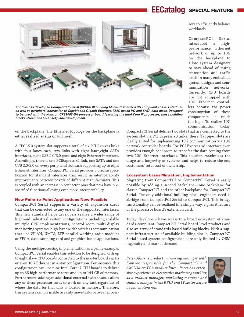
Kontron has developed CompactPCI Serial (CPCI-S.0) building blocks that offer a 3U compliant chassis platform as well as peripheral boards for 10 Gigabit and Gigabit Ethernet, XMC-based I/O and SATA hard disks. Designed to be used with the Kontron CPS3003-SA processor board featuring the Intel Core i7 processor, these building blocks streamline 10G backplane development.

Engineers’ Guide to ATCA® & MicroTCA® Technologies 201320
SPECIAL FEATURE
It’s clear that 40G ATCA products are hitting the mainstream,
especially in mobile infrastructure (especially LTE/4G) and data
center applications (cloud, anyone?). And while ARM and AMD
are making strong pushes into related markets, our experts say
they’re not taking much away from Intel’s foothold—at least,
not yet. We talked to Dr. Yong Luo, ADLINK Embedded Com-
puter Segment; Rob Pettigrew, marketing director, Embedded
Computing, Emerson Network Power; and David Hinkle, field
applications engineer, Systems Group, Elma Electronic Inc. to
get their input on these trends and more.
EECatalog: A year ago, the big move started to 40G Eth-
ernet in all kinds of applications, systems and silicon.
Where are we now?
Dr. Yong Luo, ADLINK Embedded Computer Segment: 40G is
gradually becoming mainstream for all new ATCA products
(blade, switch and chassis) both now and through the coming
year. We fully expect the volume of 40G products on the market
to ramp up over the course of 2014. Meanwhile, some 100G
prototypes may be expected from early industry adopters as
soon as late 2013. ADLINK and other vendors are running at
full speed to push our own 40G ATCA blades and chassis to the
market, but we do have some dependencies on our processor
partners to produce the required 40G NIC and switch silicon.
Emerson: We’ve been shipping 40G-ready systems for a lot
longer than a year! In fact, Emerson was the first major ATCA
company to ship 40G-ready platforms, and one of the first to
ship a working 40G switch blade and 40G payload blades. 40G
fabric bandwidth is enabling ATCA to address two particular
areas of focus—network intelligence applications with deep
packet inspection (DPI), and mobile data optimization.
David Hinkle, Elma Electronic Inc.: We are beginning to see
some boards showing up that support 40 Gig Ethernet, but the
number of available boards is still quite small. We are seeing
most of our customers building systems with 10 GigE boards
due to their more prevalent availability.
EECatalog: Intel Core iX processors are being supplemented
with other server-class initiatives such as DPDK, VPro and
more. What effect is Intel’s expanded ecosystem having on
ATCA, MicroTCA and the larger server and communications-
class markets?
Luo, ADLINK: DPDK and QAT have started gaining some
momentum in networking applications. We have seen some
cost/performance advantages of DPDK in some not-so-deep
DPI, Wi-Fi AC applications. However, QAT based on Intel
CaveCreek may still have a performance gap in the fight
against other multicore NPU solutions in the areas of security
encryption and intensive DPI/DFI.
Emerson: The most commonly deployed ATCA payload blades
are high-performance Intel Xeon processor blades, used tradi-
tionally for control plane applications, but increasingly used in
the packet data path. The telecom industry loves to talk about
the efficiencies and savings that can be gained by moving
services to the cloud. A fundamental requirement of moving
workloads to the cloud is to consolidate them on common,
general-purpose hardware. Intel calls this workload consolida-
tion. So Intel’s innovation in this area is helping enable ATCA
to address telecom cloud applications.
Hinkle, Elma: Intel has worked very hard to infiltrate and own
the server and telco markets.
EECatalog: As ARM-based processors, and to a lesser extent
AMD-based APUs, creep into this market, what are you seeing,
predicting or fearing?
Luo, ADLINK: ARM is certainly leading the way in the very
low-power space, such as in the IOT market. We have not
seen significant penetration of ARM or AMD APUs in the
infrastructure space yet.As power-saving is becoming more
and more critical, even in telecom infrastructure applica-
tions, ARM may gradually get a stronger foothold if Intel is
Left to Right: Dr. Yong Luo, ADLINK Embedded Computer Segment; Rob Pettigrew, Emerson Network Power and David Hinkle, Elma Electronic Inc
Intel Maintains its ATCA FootholdExperts discuss Intel challengers in high-performance, server-class processors, the move to 100G Ethernet and impact of new standards on ATCA-related markets.
By Cheryl Coupe, Managing Editor

www.eecatalog.com/atca 21
SPECIAL FEATURE
The main market for ATCA generally
requires high-performance, server-
class processors, which is still a
market that Intel dominates.
not aggressively promoting the application and adoption of its
advanced power management techniques.
Emerson: ARM-based processors are certainly penetrating
the market traditionally served by Intel, particularly for end-
user mobile devices. In the network datacenter, their use is
generally restricted to application delivery platforms or web
servers. The main market for ATCA generally requires high-
performance, server-class processors, which is still a market
that Intel dominates.
Hinkle, Elma: We are not
seeing ARM processors coming
into the ATCA and MicroTCA
space, although we are seeing
it in the smaller form factor
arenas.
EECatalog: What’s new in the
standards arena, either from
PICMG or other?
Luo, ADLINK: PICMG 3.7 Cloud extension to ATCA is certainly
a long-expected outcome from PICMG. Unfortunately, the
standardization process may be taking too long.
Emerson: New technologies have resulted in blades that have
pushed through the power and thermal envelope originally
written in the ATCA specification, so it is being evolved to
provide enough power and system airflow to accommodate
several technology insertion cycles.
For the ATCA fabric, a logical next step would be the evolution of
the current 40G Ethernet fabric to 100G. This step will require
first the standardization of 100G Ethernet over a copper back-
plane by the IEEE, followed by the adoption of a 100G backplane
standard by PICMG for ATCA. Such work is currently underway,
and will most likely be complete within a few years.
Hinkle, Elma: Recently completed is MicroTCA.2 and the
Physics Design Guide, while the COM Express Design Guide is
nearly finished. CompactPCI Express was recently updated to 10
Gb/s channels, following an extensive and comprehensive engi-
neering effort very comparable—and somewhat broader—than
the work done for PICMG 3.1r2. However, interest outside of the
PXIe community remains low at this point.
New work has begun on CompactPCI SO Extensions and
MicroTCA.3r2. The large effort on the ATCA Extensions con-
tinues, as well as the xTCA Physics Software working group.
EECatalog: What new capabilities will PCI Express Gen 3 bring about?
Luo, ADLINK: The best part of PCIe Gen3 implementation
that we’ve seen so far is the integration of many lanes of PCIe
Gen3 into the CPU core directly. This has largely reduced the
PCH bottleneck and brought huge improvements in terms of
latency performance.
Emerson: With PCI Express Gen 3, we see the PCI Express
bandwidth doubling from that which was available with
the previous generation Gen 2. So it fundamentally doubles
the available I/O bandwidth. Logical uses for this would be
high-performance 40G ATCA fabrics, and high-performance
storage interfaces.
Hinkle, Elma: It’s still early as
there is little board level prod-
ucts supporting PCIe Gen 3.
EECatalog: What effect will
InfiniBand have on the datacom/
telecom/fast-server market?
Luo, ADLINK: Traditionally,
people typically use InfiniBand
for their needs on low-latency and high-bandwidth applications,
if the cost is not their key concern, since it’s normally more
expensive. However, at the early stage of 40G Ethernet in 2011,
some customers/vendors have told us the total cost of a 50G+
InfiniBand solution may actually be less expensive than that
of 40G Ethernet, especially due to the scarce supply of the 40G
NIC (almost single source) and switch. This may have changed,
though, as 40G Ethernet is getting more mature and the supply
is ramping up.I guess there is a parallel situation in the gradual
shift to 100G+ scenario now. Again, Intel isn’t acting quickly
enough in this space with its InfiniBand acquisition.
Emerson: InfiniBand is typically used in datacenters as a high-
performance, low-latency storage network interface, and as
a high-performance fabric for connecting clusters of servers.
Although for many applications, InfiniBand may have superior
technical features than Ethernet, its use in the AdvancedTCA
market has largely been rejected by the market in favor of
Ethernet. This rejection was largely driven by the percep-
tion—and reality—that the much larger Ethernet market will
drive innovation and economies of scale that simply cannot be
matched by InfiniBand devices. I do not see this changing in
the future, as Ethernet speeds increase to 100G and beyond.
Hinkle, Elma: As interesting as InfiniBand is for its high-band-
width capabilities, we are not seeing it take hold in this market.
Cheryl Berglund Coupé is managing editor of EE-
Catalog.com. Her articles have appeared in EE
Times, Electronic Business, Microsoft Embedded
Review and Windows Developer’s Journal and she
has developed presentations for the Embedded
Systems Conference and ICSPAT. She has held a
variety of production, technical marketing and writing positions
within technology companies and agencies in the Northwest.

Engineers’ Guide to ATCA® & MicroTCA® Technologies 201322
SPECIAL FEATURE
Storage vendors are focusing on small form factor solutions
that will fit into smaller chassis while providing the high per-
formance that data centers require. Storage components, such
as hard disk drives, are getting physically smaller (though in-
creasing in capacity). 2.5-inch drives hold more capacity per
space occupied than the 3.5-inch drives they are replacing,
and SFF HDDs now boast storage capacities of 1 TB or more.
Choosing the right SFF configuration is an important consid-
eration for data centers because finding the right combination
of form, fit and function, allows them to deploy one SKU for
almost any configuration and simplify everything from the
purchase decision to installation to maintenance.
To match the system’s smaller footprint requirements, low-
profile storage adapters are becoming more common as well,
but delivering top I/O performance and low latency in such
a compact form factor requires changes in connection meth-
odology. Fortunately, PCI Express Gen3 doubles per-lane
bandwidth to low profile SAS and SATA drives, but requires
a minimum of 16 native 6 Gb/s ports to realize maximum
performance. This article examines the performance of PCIe
storage adapters and quantifies bandwidth as a function of
various adapter and driver parameters.
The New Generation of PCIePCI Express (PCIe) is a motherboard-mounted expansion bus
that, through a connected device such as a RAID adapter, con-
nects the host system processor to add-on peripherals, such
as storage systems. Introduced into servers and workstations
in 2012, the third generation of PCIe (PCIe Gen3) doubles
bandwidth to the host compared to its PCIe Gen2 predecessor,
increasing per-lane throughput from 250 MB/s to 500 MB/s.
With PCIe Gen2, eight 6 Gb/s SAS/SATA ports are sufficient to
achieve maximum performance. However, PCIe Gen3 requires
a minimum of 16 native 6 Gb/s SAS/SATA ports to double the
bandwidth through the storage connections.
A select group of storage adapters that claim to be designed for
PCIe Gen3 has appeared the market, but most of them max out
at eight ports and cannot take full advantage of PCIe Gen3’s
superior performance. As we will see, some SAS/SATA RAID
adapters, available with 16 or 24 native SAS/SATA ports, are
designed to fully exploit the high-performance characteristics
of PCIe Gen3 (Figure 1).
Significance of High Native Port CountIn recent years, the storage industry has been transitioning
from 3.5-inch storage drives to 2.5-inch small form factor (SSF)
drives as advancements in technology allow storage vendors to
By Juergen Frick, PMC
PCI Express Gen3 Enables Smaller, Faster Server StorageTaking advantage of PCIe Gen3 requires disk adapter silicon that’s up to the task.
Figure 1: PCIe Gen3 doubles bandwidth to storage devices; this performance can only be realized with a minimum of 16 6Gb/s adapter ports.

www.eecatalog.com/atca 23
SPECIAL FEATURE
address the aforementioned physical space challenges faced by
data centers. Not only do SFF drives offer the obvious advantage
of allowing more drives to fit into the same server rack space,
but 2.5-inch drives hold more capacity per space occupied than
the 3.5-inch drives they are replacing. Indeed, SFF HDDs now
boast storage capacities of 1 TB or more.
Additionally, the cost of 2.5-inch flash-based solid state drives
(SSDs) is finally coming more in line with HDDs in terms of the
traditional “cost per GB of capacity” metric. That—combined
with a higher read bandwidth,
higher input/output operations
per second (IOPs), better me-
chanical reliability, and higher
resistance to shock and vibra-
tions compared to HDDs—is
driving an industry-wide tran-
sition to SSDs. As the quantity
of drives in a server chassis
increases, the storage adapter
card’s port count requirements
also increase.
Expander is No OptionThe traditional method for increasing the storage adapter’s
port count has been through the use of an expander—a board
that enables the connection of additional attached SAS or
SATA devices when the adapter does not have enough ports
to accommodate them. However, expanders have a number of
limitations: not only do they add complexity, they also occa-
sionally face compatibility issues with other components in the
storage solution.
On top of that, expanders are notorious for causing latency
and limiting data transfer bandwidth. Both of these issues have
long been tolerated by data centers using HDDs, as they did not
cause a huge impact on the already slow read and write speeds
of HDDs. But as higher-performance SSDs gain traction in
storage solutions, the latency and bandwidth issues of expand-
ers have become more noticeable, and therefore less acceptable.
In a RAID 5 configuration using 24 SATA SSDs (Figure 2),
the use of expanders causes a roughly 60% performance drop
on random read IOPs, and a roughly 20% performance drop
on OLTP read/write IOPs, compared to a direct connection
through native ports.
Similarly, in a RAID 5 configuration with SATA SSDs (Fig-
ure 3), the use of expanders cause a roughly 70% performance
drop on sequential read MB/s, and a roughly 40% performance
drop on sequential write MB/s, compared to a direct connec-
tion through native ports.
This problem can be partially
overcome if SAS devices are
used, since they are dual-ported
and allow all eight SAS port
connections to be leveraged
through the expander. How-
ever, as illustrated in Figures 4
and 5, performance of the eight
6 Gb/s SAS ports f lattens out at
the peak data rate and compet-
ing products cannot match the performance of adapters with
16 or more ports, such as the Adaptec Series 7.
Another drawback of expanders is the additional cost they add to a
storage solution—about $200 for the expander itself plus the cost of
cables plus installation, increased power consumption, and main-
tenance costs. An ideal solution for data centers would be a 6 Gb/s
storage controller with a high native port count that can take advan-
tage of PCIe Gen3’s performance.
However, as mentioned, most 6 Gb/s storage adapters max out at
only eight ports.
Multiport Silicon SolutionAs shown above, higher port adapter silicon takes advantage of
the performance offered by PCIe Gen3. The Adaptec Series 7 SAS/
SATA RAID adapter family uses PMC’s 24 port PM8015 RAID-
on-Chip (ROC), which combines an x8 PCIe Gen3 interface with
6 Gb/s SAS ports to enable a new generation of high performance,
high native port count RAID adapters that are unmatched by any
other ROC in the industry.
T
o
u
a
c
t
e
a
6
t
PCIe Gen3 requires a minimum of 16 native 6Gb/s SAS/
SATA ports...to double the bandwidth.
Figure 2: RAID 5 Random Performance (24 SATA SSDs). Figure 3: RAID 5 Sequential Performance (24 SATA SSDs).

Engineers’ Guide to ATCA® & MicroTCA® Technologies 201324
SPECIAL FEATURE
Traditionally, RAID adapter performance has centered around read
and write throughput, measured in megabytes per second (MB/s).
Using this metric, our company’s adapters perform up to 83% better
than competing RAID adapters—6.6 GB/s on sequential reads and
up to 2.6 GB/s on sequential writes on parity RAID 5.
Moreover, with the popularity and growth of SSDs, input/
output operations per second (IOPs) is emerging as the new
“lead horse” in performance metrics, with the most common
configuration being the 4K random-read number. Using
4K I/O size in random scenarios is driven by the fact that
most operating systems use 4K cache sizes in the server
DRAM and, with that, 4K is typically the smallest I/O size
for random workloads. In a RAID 5 configuration with 16
direct-connected SSDs, these 16-port, PCIe Gen3 adapters
benchmark at 450K IOPs—nearly 10x the performance of
previous-generation RAID adapters, and more than double
that of the competition.
As noted earlier, RAID adapters with only eight native ports can-
not pass PCIe Gen3’s performance gains through from the bus to
the storage connections. These 16- and 24-port adapters are the
first on the market to take full advantage of PCIe Gen3 perfor-
mance gains by using HD mini-SAS connectors to offer options
with 16 or 24 native SAS/SATA ports (Figure 6)
ConclusionIn order to continue meeting customer demand for fast and reliable
access to data and content, data centers must employ efficient and
physically smaller storage solutions that maximize I/O capability
while fitting within budgetary and physical space requirements.
A new generation of PCIe Gen3 storage adapters seek to enhance
storage I/O performance by offering
16 ports required to maximize PCIe
Gen3 performance.
Series 7 adapters perform up to 83%
better than competing RAID adapt-
ers in read and write throughput—6.6
GB/s on sequential reads and up to
2.6 GB/s on sequential writes on par-
ity RAID 5—and lead the field with
450K IOPs—nearly 10x the perfor-
mance of previous-generation RAID
adapters, and more than double that
of the competition.
Juergen Frick is senior product manager of PMC-Sier-
ra’s Channel Storage Division. In this role, Mr. Frick is
responsible for Adaptec by PMC board level products
and the EMEA market. Prior to this appointment
he was the EMEA product marketing manager for
Adaptec’s RAID-Controller-products for Serial ATA
(SATA), Serial Attached SCSI (SAS) and SCSI. There he was respon-
sible for the Channel business with RAID components and for the
OEM-Business in Europe, Middle East and Africa (EMEA). Prior to
Adaptec, Mr. Frick held various positions in technical marketing at
ICP vortex and Intel.
Figure 4: RAID 5 Performance (24 SAS SSDs). Figure 5: RAID 5 Sequential Performance (24 SAS SSDs).
Figure 6: Configuration Complexities and Costs Expanders vs. Direct Connect.

www.eecatalog.com/atca 25
SPECIAL FEATURE
To address the insatiable demand for bandwidth, the
communications industry is accelerating development of
Nx100G line cards for networking systems. In order for
equipment manufacturers to scale infrastructure econom-
ically and effectively, they must leverage the latest optical
interconnect technologies such as CFP2, and in the future
CFP4, to increase bandwidth while lowering power and cost.
By working with network developers, Xilinx anticipated
this need and developed transceiver- rich, high-perfor-
mance, programmable devices comprised of heterogeneous
silicon die. The technology supports the required 28
gigabits per second (Gb/s) channels for CFP2 optics and
delivers optimal signal integrity due to its heterogeneous
architecture. With high logic capacity and specific IP
for communications applications, these devices provide
extensive levels of system integration to usher in the
migration to next-generation optics.
Demand for BandwidthLargely driven by streaming video, HD video, cloud com-
puting, and mobile networking, the consumer market’s
relentless demand for network bandwidth compels the com-
munications industry to double system capacity every three
years. Service providers supporting the Internet’s backbone
must lead the migration to 100G and 400G and stay at the
forefront of the latest technologies and standards.
Service providers not only demand more bandwidth but aim
to reduce capital and operating expenses. For equipment
manufacturers, this means rolling out solutions with leaps
in performance, area efficiency, and cost effectiveness over
previous generation products.
The Move to Next-Generation Optics for Nx100GMost of today’s network infrastructure is connected via
optical fiber, hence the bandwidth and cost of optical
modules are major development considerations. The type
of modules that can be used depends on the architecture
of the application’s line cards. Three well-known optical
module standards include SFP+, CFP, and CFP2—each with
varying throughput, cost per bit, power efficiency, and form factor:
10G optical links and are currently shipping in high volume.
support 100G optical links. Though they consume more
power per bit than SFP+, integration to a single 100G fiber
greatly reduces complexity and serviceability costs.
a CFP, but in half the space, at a reduced cost, and consumes
half to two-thirds less power.
Because of the 2X bandwidth-per-watt efficiency gained
from CFP2 modules over CFP, the industry is eager to
move to these optics. Without this technology, the cost
of migrating to 100G is prohibitive for many service
providers. The need for CFP2 is demonstrated in Figure
1, showing a comparison of optical interfaces as they
appear on the faceplate connector of a fixed-width line
card. Because service providers postpone upgrading
their chassis until economically feasible, network OEMs
must strive to provide more capabilities within the same
Scaling 100G Wired Applications with Heterogeneous 3D FPGAsNext-gen 100G line cards require optical interconnects which are efficiently supported by FPGAs like the Virtex-7.
By Ehab Mohsen, Xilinx
CFP2 CFP2 CFP2 CFP2 CFP2 CFP2 CFP2 CFP2
CAUICAUI CAUI
CAUI
CAUI
48 SFP+480 Gb/s48 Watts
4 CFPs400 Gb/s60 Watts
8 CFP2s800 Gb/s60 Watts
ASSP
MAC to
Inte
rlake
nBr
idge
MAC to
Inte
rlake
nBr
idge
MAC to
Inte
rlake
nBr
idge
ASSP
MAC to
Inte
rlake
n
Brid
ge
100GEMapper
100GEMapper
100GEMapper
100GEMapper
Interlaken Interlaken Interlaken Interlaken
CAUICAUICAUI
CFP CFP
48 SFP+
CFP CFP
ASSP
ASSP
Figure 1: Throughput and Power for Line Cards and Face Plate
Connectors of Fixed Width

Engineers’ Guide to ATCA® & MicroTCA® Technologies 201326
SPECIAL FEATURE
unit area and power envelope. Scaling bandwidth within
existing infrastructure is driven by throughput per watt
per unit area of optical ports.
When using SFP+ optical modules to connect 10G optical
links, the top faceplate connector shown in Figure 1 can
accommodate 48 fiber links. The arrangement in this
example provides 480 Gb/s of throughput.
Comparatively, four CFP ports can be designed in the same
footprint of 48 SFP+ modules. With each CFP accommodating
a single 100G fiber link, this provides a total of 400 Gb/s of
bandwidth. Though there is a slight increase in power, the
integration reduces complexity and serviceability.
A CFP2 module, by contrast, provides the same 100G
bandwidth of a CFP in half the width while consuming half
the power per 100G port. In this example, within the same
area, a module could accommodate eight CFP2 ports for
an aggregate 800 Gb/s bandwidth within the same 60W
power envelope. This is 33% higher bandwidth and power
efficiency compared to SFP+ and double the efficiency pro-
vided by CFP modules.
The Challenge of Redesigning the Line Card for Nx100GMigrating to CFP2 has its benefits, but the need for higher
density front plates poses challenges on the line card itself.
Effective integration is needed on the silicon side to sup-
port the incoming bandwidth so as not to nullify the power
and cost efficiencies promised by a CFP2 transition.
A typical 100G transponder is shown in Figure 2, with an
optical interface at one end and a backplane interface at the
other. Typically, there is a forward error correction (FEC)
block to minimize packet retransmission and framing and
mapping functions to handle data transport. Transceiver
interfaces such as CAUI are used for chip-to-chip commu-
nication, and Interlaken can be used for chip-to-chip or
backplane communication.
To redesign the line card for 2X bandwidth, the interface
to CPF2 must first be considered, given that it can support
4x25G channels versus the 10x10G channels supported
for CFP.
Using simple bit multiplexing, a functional block known
as a “gearbox” can convert a 100G interface comprised of
4x25G channels into 10x10G channels, allowing these
modules to interface with existing silicon infrastructure.
Consequently, the original devices (ASICs, ASSPs, or
FPGAs) that operate via 10x10G do not necessarily need
to be replaced to support CFP2. The gearbox maps data
between the ten and four serial lane interfaces, in both
ingress and egress directions. It converts data streams
of either four lanes of CAUI4 (4x 25.78G) or OTL4.4 (4x
27.95G) to CAUI (10x 10.3125G) or OTL4.10 (10x 11.18G).
Although the gearbox addresses optics connectivity, it still
does not address the 2X bandwidth requirement. If the
CFP is replaced by two CFP2 modules, the system either
has to support additional components of similar type
within the same area or support completely new silicon to
support 2x100G throughput. Migrating to new ASSP and
NPU architectures can be prohibitive in terms of cost and
schedule, and a new implementation using similar compo-
nents has its own challenges. A re-design of the line card
to support 2x100G using similar components and gearbox
ASSPs is shown in Figure 3. The increased number of
components requires more area on the PCB. Even if such a
layout is feasible, the increase in cost and power consump-
tion can nullify the advantages of a CFP2 migration.
28G Enabled FPGAs as a SolutionFPGAs play a critical role in networking equipment because
of their f lexibility and ability to rapidly implement the
latest networking standards, even as these standards
evolve. FPGAs have also evolved to meet next-generation
networking requirements by delivering greater capacity,
performance, and features, along with more robust trans-
ceivers supporting higher line rates.
To interface to CFP2 modules, FPGAs must provide 25G–
28G serial interfaces with support for advanced protocols
and interface specifications. These include 100GE, OTU4,
400GE, CAUI, CAUI4, OTL4.4, SFI-S and other standards.
A line card without 28G support simply cannot interface
to CFP2 optics.
Transceiver support is only half the challenge for successful
28G design. Signal integrity is another consideration at
this transmission rate. The CEI-28G specification guiding
the electrical specifications for 28G imposes very tight
transmit jitter budgets (0.30 UI) on system designers and
requires robust equalization techniques in the receiver to
build 28G chip-to-optics interfaces.
CFP CAUI100GFEC
OTU-4Framer
100GMapper
MACto
InterlakenBridge
10x11.1GOTL4.10
CAUI Interlaken
BackplaneInterface
Figure 2: Generic 100G Transponder Line Card.
Figure 3: Five Devices Required to Redesign Transponder to Support
CFP2 and 2x100G.
Gearbox CAUI100GFEC
OTU-4Framer
100GMapper FPGA
MACto
InterlakenBridge
CAUI
CAUI100GFEC
OTU-4Framer
100GMapper
10x11.1GOTL4.10
4x27.9GOTL4.4
CAUI
Interlaken
BackplaneInterface
ASSPASSP
ASSP
Gearbox
ASSP
CFP2
CFP2

www.eecatalog.com/atca 27
SPECIAL FEATURE
FPGA “Wired” for Communications ApplicationsXilinx Virtex-7HT FPGAs were designed to match these
unique requirements, addressing the bandwidth needs, signal
integrity challenges, and integration demands. As a single
chip solution enabling Nx100G applications, the Virtex-7 HT
FPGA ushers in the transition to CFP2 optical modules.
The Virtex-7 family is based on 3D stacked silicon inter-
connect (SSI) technology, which combines enhanced FPGA
die slices known as super logic regions (SLRs) and a passive
silicon interposer to create a three-dimensional die stack.
This interposer implements tens of thousands of die-to-
die connections to provide ultra-high inter-die bandwidth
with lower power consumption and one fifth the latency of
standard I/Os. The device shown in Figure 4 ties together
three SLRs fabricated on 28 nm. Next to these SLRs are
separate 28G transceiver die. This kind of 3D SSI tech-
nology outpaces Moore’s law in performance, capacity and
power efficiency.
Heterogeneous Silicon for Low Jitter and Noise IsolationThe combination of SSI technology with traditional FPGA
SLR slices and 28 Gb/s transceiver slices delivers the
world’s first heterogeneous device.
Xilinx employs a unique approach to isolate the digital logic
from the analog transceiver circuit on the same interposer,
as shown in Figure 5—in essence, placing heterogeneous
die side-by-side to operate as one integrated device. If this
were a monolithic device—the approach of competing
solutions—the digital logic region would create a noisy
environment that degrades transceiver performance. The
electrical isolation of the digital
and analog circuits in a hetero-
geneous device allows for low
noise and jitter. This simplifies
the job of PCB and layout engi-
neers, accelerates 28G design
closure, and reduces board cost.
In addition to noise isolation,
the transceiver’s jitter per-
formance is improved with a
narrowly tuned phase-locked
loop (PLL) based on an LC tank design. Unique clocking,
clock distribution, and PLL design minimizes jitter across
multiple transceivers. Additional design features minimize
lane-to-lane skew to support tough optical standards like
the Scalable SerDes Framer Interface (SFI-S), which limits
acceptable skew to 500 ps.
To compensate for channel loss and maintain signal integ-
rity, Xilinx 28G transceivers employ a programmable main
transmit driver, programmable transmit pre-emphasis,
and an auto adapting continuous time linear equalizer
(CTLE) in the receiver.
The eye diagram in Figure 6 demonstrates the low jitter
and high signal quality of the 28G FPGA transceiver on
the Virtex-7 XC7VH580T device. The 28G transceiver
presents an open eye without excessive over-equalization.
The heterogeneous architecture also enables ample trans-
ceivers of two types:
chip-to-chip, and backplane connectivity.
networking.
The Virtex-7 XC7VH870T device offers up to sixteen 28G
transceivers—4X the competition—making it uniquely
matched to interface to up to four CFP2 modules for
4x100G applications or 400 Gigabit Ethernet. With an
additional seventy-two 13.1 Gb/s GTH transceivers on the
same device, system designers have multiple options for
chip to chip connectivity, including Interlaken, Ethernet,
and OTN. With up to 88 transceivers overall, the Virtex-7
Figure 4: Xilinx Stacked Silicon Interconnect Technology (side view).
28 nm FPGA Slice 28 nm FPGA Slice 28 nm FPGA Slice
Silicon Interposer
Package Substrate
28G Transceiver
Side-by-Side Die Layout
Die-to-Die Interconnects
28G Transceiver
Figure 5: Heterogeneous 3D FPGA Enables Low Jitter 28G Transceiver
Design.
28GTransceivers
28GTransceivers
Passive Interposer
13G Transceivers
NoiseIsolation
Super Logic Region(Homogeneous Die)
Different Types of Silicon(Heterogeneous Die)
Figure 6: 28 Gb/s Eye Diagram of GTZ Transceiver on the Virtex-7 H580T
FPGA.

Engineers’ Guide to ATCA® & MicroTCA® Technologies 201328
SPECIAL FEATURE
HT device is the highest bandwidth FPGA available at
28nm, providing 2.87 terabits per second (Tb/s) of bidi-
rectional throughput.
Gearbox IP to Enable System IntegrationAs important as CFP2 connectivity is, the intellectual prop-
erty (IP) cores needed for the line cards are equally critical.
Xilinx provides gearbox IP that handles 4x25G to 10x10G
conversion. It also supports a 10x10G-to-10x10G pass-
through mode.
While a single Virtex-7 HT FPGA can provide up to 4x100G
throughput via its gearbox IP connecting to up to four CFP2
ports, competing FPGA or ASSP solutions can provide only
100G throughput on a single device. As already shown in
Figure 3, if an ASSP approach were taken to upgrade the
line card, separate gearbox chips would be needed, thereby
increasing cost, power consumption, and board complexity.
The other benefit of using an FPGA is flexibility when inte-
grating IP. With Virtex-7 HT devices, designers can take
integration to the next level by combining gearbox, Ethernet
MAC, OTN transponder, OTN muxponder, Interlaken, dif-
ferentiating IP, and standard or proprietary chip-to-chip or
backplane interfaces (e.g., XAUI, Interlaken) within the FPGA.
A Comparison of Two TranspondersA 2x100G line card is shown in Figure 7, where a Virtex-7
HT device is used to integrate the functionality of two
gearboxes, a MAC, and Interlaken bridge. The simplicity
of this architecture is in stark contrast to the 5-chip alter-
native in Figure 3. A designer can implement four of these
Virtex-7 HT devices, producing an 8x100G system that
can interface with eight CFP2 ports. An equivalent scaling
of the ASSP implementation would require 20 devices—
consuming excessive area, increasing PCB cost and power,
and likely lengthening the project schedule.
Based on Xilinx estimates of pricing and power consump-
tion of ASSPs advertised on the market, a power-and-cost
comparison of the two line card implementations is shown
in Table 1. The ASSP-based solution is comprised of five
devices, consumes at least 40% additional power and
costs 50% more than the FPGA implementation. Unac-
Gearbox 100GFEC
OTU-4Framer
100GMapper
13G
(GTH
) Tra
nsce
iver
s
28G
(GTZ
) Tra
nsce
iver
s
Interlaken
100GFEC
OTU-4Framer
100GMapper
Interlaken
BackplaneInterface
Virtex-7 HT FPGA
Gearbox
CFP2
CFP2
Figure 7: 2x100G Transponder Using a Single Virtex-7 FPGAs.
counted for is the productivity and time-to-market gain
from the simplified layout and integration of a single FPGA.
Enabling CFP2 Connectivity and BeyondThe market need for higher-bandwidth networking line
cards and next-generation optics is real. Xilinx is at the
forefront of this movement with a heterogeneous architec-
ture that provides the bandwidth and capacity for adopters
of 100G and 400G, based on CFP2 optics. Without an FPGA
solution of this caliber, the migration would not only be
sub-optimal, but costly. By leveraging FPGAs, designers
get a level of integration that is two-fold: optical connec-
tivity at the system level and IP integration at the silicon
level. By targeting Virtex-7 HT devices, designers achieve
the greatest possible port density, protect themselves
against evolving standards, and prepare themselves for
optics even beyond CFP2.
Ehab Mohsen is a product marketing manager in
the FPGA Platform Marketing Group at Xilinx.
Prior to Xilinx, Ehab held technical marketing po-
sitions at Mentor Graphics and Aptix Corporation.
With over 10 years experience in FPGA-related
industries, Ehab holds a BSEE from the University
of California, Berkeley.
ASSP Implementation Costs (vs. Xilinx HT FPGAs)
Power Consumption 40% or greater
BOM Cost 50% or greater
XC7VH580T XC7VH870T
Logic Cells 580,480 876,160
GTH Transceivers (13G) 48 72
GTZ Transceivers (28G) 8 16
Types of Applications 2x100G 400G
Table 1: Power/Cost of ASSP Implementation vs. FPGA-Based 8x100G
Line Card.
Table 2: Virtex-7 HT Family and Key Types of Applications.

CONTACT INFORMATION
Adax Inc.
Adax Inc.2900 Lakeshore AveOakland, CA 94610USA+1 510-548-7047 Telephone+1 510-548-5526 [email protected]
◆ Processor:
(option)◆ Ethernet Controller:
◆ Memory:
◆ Interfaces:
AVAILABILITY
Available Now
APPLICATION AREAS
Adax PacketRunner Intelligent ATCA Carrier Blades
Compatible Operating Systems: Linux
Specification Compliance:
Belcore GR-63-CORE
Cavium-based, 4-bay ATCA carrier blades for telecom applications. The on-board Cavium OCTEON 5650 multi-core processor with memory and cache gives developers
LTE, 4G, and all other demanding telecom network appli-cations. The APRs deliver the perfect ATCA subsystem for secure user and control plane applications.
The APRs uniquely offer I/O and processing scalability with access to the host Cavium. All at a viable price point for IP transport, packet processing and signaling on a single blade
is the industry’s most cost-effective, multi-purpose solution in one tightly coupled resource.
ATCA’s promise of horizontal expansion at a reduced cost. In a redundantly designed system, cards and blades may be added, removed, and reallocated with no loss of service and network operators are able to retain the value of their initial CAPEX investment well into the future.
FEATURES & BENEFITS
◆ Cavium OCTEON Plus CN5650, 12 cores at 750MHz - Option for CN5430, 4 cores at 700 MHz
◆
(LiS), SIGTRAN, HDC3 and ATM4 board drivers
◆ 4 AMC bays for Adax and/or 3rd party mid-size AMC cards◆ 2 GB of DDR2 Memory - Options for 4 GB and 8 GB
DDR2 Memory◆
- 1x 10GbE and 2x 1GbE to each AMC bay Common to
Base domain - 10 GbE from Cavium to switch
TECHNICAL SPECS
◆ Standards:
BladesB
lade
s

® ®
CONTACT INFORMATION
CONTACT INFORMATION
AdvantechNo. 1, Alley 20, Lane 26, Rueiguang Road, Neihu DistrictTaipei, Taiwan 11491Telephone 886-2-2792-7818Toll Free [email protected]/nc
FEATURES & BENEFITS
◆ Dual Cavium OCTEON II CN6880 1.0 GHz with 32 cnMIPS™ II proces¬sor cores
◆ Up to 64 GB DDR3 1066 MHz DIMMs; 32 GB for each CN6880
◆ 2*40 GbE (KR4) or 8*10 GbE (KR) FI support and Dual Star routing support
◆ Eight 10GbE SFP+ and four 1GbE SFP Rear I/O support
◆ Switch management support on L2, QoS, Multicast (SW options)
ATCA-7310 Dual Cavium OCTEON CN6880 ATCA Blade with 40G Switch
WindRiver Linux 4.2
Based on dual Cavium OCTEON® II CN6880 32-core MIPS64 processors and a Broadcom BCM56842 40G switch, the ATCA-7310 Packet Processing Engine is targeted at high-end control, service and dataplane applications in 4G/LTE networks, video/data applications in cloud computing, and security applications using Deep Packet Inspection (DPI). The blade supports up to 32GB of DDR3 1066MHz DIMMs per OCTEON II. 40GbE(KR4) FI connectivity is supported with 8x10GbE and 4x1GbE to the Zone3 RTM. Independent management and console servers are supported for each processor. The BSP offers flexible power throttling options for the OCTEON II’s. Software management is also sup-ported for firmware upgrade to the LMP.
Advantech Co., Ltd.
Blades B
lade
s
www.eecatalog.com/atcaATCA & MicroTCA Technologies ONLINE
Explore...➔ Directory of leading ATCA, MicroTCA and
AdvancedMC Solutions
➔ Top Stories and News
➔ White Papers
➔ Expert Opinions (Blogs)
➔ Exclusive Videos
➔ Valuable Articles
➔ Ask the Experts
Sign up for the quarterly AdvancedTCA & MicroTCA E-Product Alert

CONTACT INFORMATION
Advantech Co., Ltd.
FEATURES & BENEFITS
◆ 20 Texas Instruments TMS320C6678 DSPs 512MB-2GB DDR3 memory per DSP
◆ IDT Tsi577 Serial RapidIO switches BCM56321 10GbE switch for both Fabric Interface and Base Interface
◆ Freescale QorIQ™ P2020 for Local Management Processor (LMP)
◆ Pigeon Point Systems IPMI 2.0
DSPA-8901 AdvancedTCA DSP Blade Compatible Operating Systems: WindRiver Linux PNE-LE 4.0/Freescale SDK for P2020 support
With its 20 onboard TMS320C6678 DSPs at 1.0GHz core frequency, the DSPA-8901 provides 160 cores of processing power to reach the levels of performance density needed to build the highest capacity media gateways. The DSPA-8901 significantly reduces overall system power dissipation and system cost, and frees up valuable slots in gateway elements for additional subscriber capacity and throughput. It includes a high-performance Freescale QorIQ P2020 processor. A Broadcom BCM56321 switch terminates the 10 Gigabit Ethernet fabric connections and distributes traffic to the 20 DSPs. The DSPA-8901 offers unrivaled packet and media processing capabilities. For increasing demand in high-end video conferencing, broadcasting and tele-presence fields, the DSPA-8901 ATCA blade also offers unmatched image processing performance for compres¬sion and decompres-sion, image analysis, etc.
CONTACT INFORMATION
AdvantechNo. 1, Alley 20, Lane 26, Rueiguang Road, Neihu DistrictTaipei, Taiwan 11491Telephone 886-2-2792-7818Toll Free [email protected]/nc
Advantech Co., Ltd.
Blades B
lade
s
AdvantechNo. 1, Alley 20, Lane 26, Rueiguang Road, Neihu DistrictTaipei, Taiwan 11491Telephone 886-2-2792-7818Toll Free [email protected]/nc
FEATURES & BENEFITS
◆ Two Intel® Xeon® E5 Series processors with Intel® Communications Chipset 89xx Series
◆ 8 DDR3 VLP DIMMs with ECC
◆ Up to four 40GBaseKR4 ports on Fabric Interface to support Dual-Dual Star Topology
◆ Other fabrics supported via two Fabric Mezzanine Module (FMM) sites
◆ One FMM for optional front I/O or acceleration
MIC-5333 Dual Intel® Xeon® E5 Series ATCA Blade with Dual-Dual 40G Fabric Support Compatible Operating Systems: WindRiver Linux, RedHat Enter-prise, CentOS6.1, Windows Server 2008
The MIC-5333 enables the highest network and packet processing performance available on ATCA with up to 20 cores of processing power, scalable offload based on Intel® QuickAssist technology and support for up to four 40G fabric ports. PCIe gen. 3 running at 8Gbps per lane and best in class virtualization combined with superior thermal design make it ideal for high performance workload consolidation on Intel architecture. Two QPI interfaces between CPUs improve memory I/O access throughput and latencies when one processor needs to access resources hosted by the other socket. Four DDR3 DIMMs per socket in a quad channel design running up to 1600MT/s offers superior memory bandwidth over 3-channel designs, and supports memory densities up to 256GB using latest LR DIMMs. It outperforms previous generation designs while keeping similar thermal characteristics with balanced airflow resistance.
Engineers’ Guide to ATCA® & MicroTCA® Technologies 2013
CONTACT INFORMATION
CONTACT INFORMATION
Emerson Network Power
Emerson Network Power 2900 South Diablo Way, Suite 190Tempe, AZ 85282USA+1 602 438 5720 Toll Free+1 800 759 1107 Telephone +1 602 438 5825 [email protected]
Emerson.com/EmbeddedComputing
◆
◆ Designed for NEBS/ETSI or network datacenter
APPLICATION AREAS
Wireless infrastructure, mobile data optimization, net-work policy enforcement and access control, voice core elements, media gateways, session border controllers
Centellis™ Series ATCA® Systems
Emerson has been supplying integrated, application-ready ATCA® systems under the Centellis™ name for over 10 years. Our unrivalled experience and expertise is why new research reports that Emerson is number 1 in ATCA market share and installed base. Our Cen-tellis systems include 2-slot, 6-slot and 14-slot variants designed to meet the needs of telecom central office environments. As the only major ATCA systems vendor that designs and manufactures its own chassis, Emerson understands how to build systems that are capable of meeting your requirements. We also have the only 2-slot and 6-slot systems available with AC power options and front-to-rear cooling, meeting the needs of both central office and network data center deployments.
FEATURES
◆ 40G systems with 2-, 6- or 14-slots◆ Best-in-class cooling, exceeding CP-TA B.4 thermal
specification◆ AC or DC power input options
BladesB
lade
s
CONTACT INFORMATION
Emerson Network Power 2900 South Diablo Way, Suite 190Tempe, AZ 85282USA+1 602 438 5720 Toll Free+1 800 759 1107 Telephone +1 602 438 5825 [email protected]
Emerson.com/EmbeddedComputing
Emerson Network Power
◆ ◆ Redundant 40G active/active ATCA Fabric interfaces,
backward compatible with previous 10G systems◆ Optional hardware off load module for encryption and
compression acceleration with two Intel® Communica-tions Chipsets 8920 devices
◆ Multiple 1 and 10Gbps network and storage I/O connec-tivity options
ATCA-7470 Dual Intel® Xeon® Processor-based 40G ATCA® packet processing blade
Emerson’s ATCA-7470 is a 40G ATCA® packet processing blade that enables the highest packet processing perfor-mance and security features. You can consolidate packet, application and control processing functions in a single blade architecture and benefit from lower development costs and the use of common tool suites. This can get you to market faster and enable you to balance work-loads efficiently across available hardware resources.
-figured to provide a perfect fit to the needs of your application. Multiple available rear transition modules
options for high capacity redundant storage or up to 6x10G Ethernet interfaces.
FEATURES
◆ Two 8-core Intel® Xeon® processors E5-2648L, 1.8 GHz or E5-2658, 2.1 GHz
BladesB
lade
s

CONTACT INFORMATION
Scan Engineering Telecom GmbH
Scan Engineering Telecom GmbHElisabethstrasse, 91Munich, 80797Germany+49 89 5908 2347 Telephone+49 89 5908 1200 [email protected]
TECHNICAL SPECS
◆ Four high-performance TI TMS320C6457 DSPs, each running up to 1.20GHz
◆ Peak performance 38400MIPS◆ Integrated Viterbi and turbo-code processors ◆ Total DDRII memory capacity 512/1024MB◆ 2 x Gigabit Ethernet and 2 x Serial RapidIO x4 on
AMC edge connector
AVAILABILITY
Available now
APPLICATION AREAS
Gateways, Media servers, Security appliances, Broad-cast, Data Processing, Industrial Automation, Medical Imaging, Wired Communcations, Wireless Communica-tions, Wireless infrastructure
SAMC-404 High-performance DSP boardCompatible Operating Systems: Windows, Linux
Specification Compliance: AMC.0 R2.0, AMC.2, AMC.4
The SAMC-404 Single Mid-/Full-Size AMC board is a high performance computing module for use in AdvancedTCA® and MicroTCA™ systems. Designed around high-performance TI TMS320C6457 DSPs, com-bining a wide range of fabric interfaces and colossal amount of memory, it provides exceptional computing power and performance in the convenient and versatile AdvancedMC™ form factor.
The SAMC-404 complies with the most current PICMG® specifications for operation in ATCA and MicroTCA applications. This module supports sub-specifications to insure compatibility with the broad set of interface options presented by AMC carriers – including Ethernet and Serial RapidIO. SAMC-404 gives OEMs in a broad range of industries a high-performance and cost effec-tive solution for reducing size, complexity, risks and costs associated with leading-edge software-defined radio (SDR), networking, telecommunication, data pro-cessing, industrial and medical applications.
Scan Engineering Telecom can also provide custom-ization, turnkey integration and support to ensure that OEMs can focus where they prefer to add their own unique value.
FEATURES & BENEFITS
◆ High-performance AdvancedMC DSP board◆ 4 TI DSPs provides exeptional peak performance◆ A very cost-effective computing platform for
AdvancedTCA and MicroTCA solutions◆ For OEMs in telecom, datacom, industrial, medical
test & measurement and aerospace industries◆ Customization welcomed
BladesB
lade
s

® ®
CONTACT INFORMATION
Scan Engineering Telecom GmbH
Scan Engineering Telecom GmbHElisabethstrasse, 91Munich, 80797Germany+49 89 5908 2347 Telephone+49 89 5908 1200 [email protected]
TECHNICAL SPECS
◆ Intel 2nd Generaiton Quad-Core Core-i7 CPU operat-ing at 2.10GHz
◆ Up to 8GB soldered 1333MHz DDRIII memory with ECC support
◆ Up to 128GB SATAII SSD drive◆ 2 x PCI Express Gen2 x4/Serial RapidIO x4/XAUI
lanes, 2 x PCI Express Gen2 x4 lanes, 2 x Gigabit Ethernet, 2 x SATAIII on AMC edge connector
◆ Front panel interfaces – HDMI, 2 x Gigabit Ethernet, 2 x USB 2.0, 1 x Serial
AVAILABILITY
Q2’2011
APPLICATION AREAS
Telecom – Edge applications, next-generation convergent media gateways, media servers, messaging servers, ses-sion border controllers, WiMAX and LTE base stations Datacom/Enterprise computing – Routers/gateways, network security/firewall appliances, switches Industrial – Embedded controllers, co-processor applications Med-ical – Imaging, X-Ray, Ultrasound Instrumentation – Test & Measurement systems Aerospace – Avionics and ship-board platforms, Communication systems, Real-Time Intelligence systems, Simulators
SAMC-514 Quad-core Processor AMC based on Core i7
Windows, Linux
AMC.0 R2.0, AMC.1, AMC.2, AMC.4
The SAMC-514 Singe Full-Size Processor AMC board is the second generation of SET’s high-performance Quad-Core Processor AMC boards.
The SAMC-514 is intended for use in AdvancedTCA® and MicroTCA™ systems. Designed around 2nd Genera-tion Intel Core i7 CPU (Sandy Bridge), combining a great amount of soldered DDRIII memory and unsurpassed range of fabric interfaces, it provides exceptional com-puting power and performance in the convenient and versatile AdvancedMC™ form factor.
The SAMC-514 complies with the most current PICMG® specifications for operation in ATCA and MicroTCA applications. This module supports sub-specifications to insure compatibility with the broad set of interface options presented by AMC carriers – including SAS/SATA, Ethernet, PCI Express. It also features an onboard SATA SSD disk drive and option for Serial RapidIO/XAUI system interconnect for extend typical application areas.
SAMC-514 gives OEMs in a broad range of industries a higher performance and cost effective solution. Scan Engineering Telecom can also provide customization, turnkey integration and support to ensure that OEMs can focus where they prefer to add their own unique value.
FEATURES & BENEFITS
◆ High-performance AdvancedMC processor module with broad range of front and rear connection options
◆ Support options for system interconnect via PCI Express Gen2, SATAIII, Serial RapidIO Gen2 and XAUI
◆ A very cost-effective computing platform for AdvancedTCA and MicroTCA solutions
◆ For OEMs in telecom, datacom, industrial, medical test & measurement and aerospace industries
◆ Customization welcomed
BladesB
lade
s

CONTACT INFORMATION
Advantech Co., Ltd.
FEATURES & BENEFITS
◆ Freescale P4080 8-core e500-mc PowerPC, up to 1.5 GHz (AMC-4201)
◆ Freescale P5020 2-core 64bit e5500 PowerPC, up to 2.0 GHz (AMC-4202)
◆ Up to DDR3 1300 MHz 8 GB with ECC support ◆ 4 MB SPI Flash and 2 GB NAND Flash
AMC-4201/4202 Advanced Mezzanine Card Freescale QorIQ P4080 / P5020 AMC Compatible Operating Systems: WindRiver Linux 4.3, Freescale DPAA SDK1.0 (Optional)
Specification Compliance: PICMG AMC.0, AMC.1, AMC.2, AMC.3, AMC.4, IPMI v1.5, HPM.1, NEBS Level 3 (Design compliant)
The AMC-4201 and AMC-4202 are single-width, mid-size AMCs based on the Freescale P4080 and P5020 processors. AMC-4201 combines eight Power Architecture® e500-mc Cores at frequencies up to 1.5 GHz with high-performance, datapath acceleration logic, extensive networking I/O, and peripheral bus interfaces. AMC-4202 combines two 64-bit ISA Power Architecture™ e5500-mc cores with high-performance datapath acceleration logic and network and peripheral bus interfaces required for networking, telecom-munications, and wireless infrastructure. Both cards provide 2, 4 and 8 GB build options for onboard DDR3 memory at 1300 MHz with ECC support. One front-panel 10GbE SFP+ connector provides network access in addition to a front panel console and debug port. The unique SERDES design supports up to four different AMC port configurations for a mix of SRIO, PCIe, and SGMII channels.
Boards / B
oard Accessories B
oard
s / B
oard
Acc
esso
ries
CONTACT INFORMATION
AdvantechNo. 1, Alley 20, Lane 26, Rueiguang Road, Neihu DistrictTaipei, Taiwan 11491Telephone 886-2-2792-7818Toll Free [email protected]/nc
Browse the EECatalog White Paper Library
www.pt.com
Integrate up to 40GbE High Performance Networking into the Aggregation Layer
with Enhanced MicroTCA.4
By Tony RomeroSenior Product Manager
Bridge the Gap:AdvancedTCA – MicroTCA®
WHITE PAPER
White Paper
Make Your Tablets and Smart Phones Smarter – Add Serial Capability for Seriously Remote Data
To paraphrase Mark Twain, rumors about the demise of serial ports are greatly exaggerated. Serial ports are everywhere, in everything from industrial automation systems to scientific instrumentation. Too many people have too much invested in serial-equipped devices for the standard to disappear any time soon. But as data communications technology continues to evolve, the humble serial port is sometimes left behind. This article will review serial device server technology, its usefulness and drawbacks, and then demonstrate how to access serial data from locations that are either remote or restricted and therefore out of range of a Wi-Fi network.
Back when the first serial device servers were introduced they closed a connectivity gap between connected devices and remote networked PCs. The development of the serial-to-Ethernet device server in the late 90’s was another huge step forward. Later, the advent of USB made accessing serial data from desktops and laptop PCs easier than ever.
But as tablets and smart phones become more ubiquitous in the corporate and M2M business world, connecting to serial ports has become a bit more complicated. Tablets and smart phones don’t have serial ports. In fact they tend to have limited wired connectivity of any kind, largely relying upon wireless communications for their interaction with the rest of the world. They’re wonderful devices, but they’re not natively designed to interact with serial equipment.
Manufacturers, suppliers and integrators of M2M equipment – as well as their customers -- have a continuing need for serial communications. So what can they do about the communications gap?
How does it work now?Serial device servers can be wired or wireless. The most popular types are network or TCP/IP device servers. In either case -- wired or wireless -- the serial server translates the serial data into an Internet Protocol (IP) format that can be transmitted across a network.
Wired serial device servers use Ethernet cable to connect to the local area network (LAN).
Wireless device servers contain a Wi-Fi client similar to the one in your laptop and connect via Wi-Fi, or 802.11. (The most common standards are 802.11b/g and 802.11b/g/n.) Wireless servers can connect to either an infrastructure network or to an AdHoc network.
When the Serial Device Server (SDS) network interface is connected to a LAN it provides an IP address that all other network devices can use for sending and receiving information. This address is unique to the SDS. Since this address is the location for all interactions, a secondary reference is used to locate the information or resource required for the specific interaction. This is called a port number.
Introduction to Smarter SystemsThe global electronics industry is undergoing a transition to smarter systems. The drivers behind this change are all connected to
requirements involving efficiency, productivity, security, quality, and of course cost. The enemy is waste. Systems reduce waste
when they use only the required resources to deliver only the desired goods and services when and where they are needed. The
opportunity is intelligence. Systems that can make their own decisions can change the role of electronics in our businesses and
everyday lives. To achieve these goals, systems must be able to obtain, process, interpret, and make choices based on a wide
variety of information from remote and local databases, sensor data, and many other dispersed inputs.
What does this transition to smarter systems mean to system vendors? It means that there must be more decision-making
technology and intellectual property. The networks that convey essential information are being transformed from dumb pipes to
smart ones. Buildings are becoming smarter so that light and heat are delivered only where needed. Highly integrated networking
has come to the factory floor to ensure that every system has access to critical data needed to make decisions. Robots within
these factories combine information from databases with machine vision to become more efficient. Energy grids are becoming
smarter so that electricity infrastructures can handle the changing loads of complex societies. Automobiles are becoming smarter
through vision systems and wireless communications to increase drivers’ safety and to help drivers handle the increasing traffic
congestion in urban areas.
The Xilinx Zynq™-7000 All Programmable SoC is the ideal platform to infuse intelligence into today’s embedded systems. It is
All Programmable, meaning that not only can one add systems intelligence through software, but additional data processing and
decisions can be executed in real time with programmable
hardware and system interfaces can be optimized and evolved
through programmable I/O. All this intelligence can be added
with low design costs and tremendous flexibility to change
the design or upgrade in the field. It also enables a significant
level of programmable systems integration, including CPU,
DSP, ASSP, FPGA, and mixed signal functionality. This leads
to lower BOM cost, higher systems performance, and lower
system power. Systems based on the Zynq platform can
literally be shipped the same day if desired.
Xilinx Zynq-7000 All Programmable SoCs are the fastest,
smartest way to create smarter systems. These devices
fuse a fast processor system based on two 1GHz ARM®
Cortex™-A9 MPCore processors with the industry’s fastest
and most advanced 28nm FPGA fabric, multiple high-speed
serial transceivers, and an on-chip analog-processing block
that incorporates two 1Msamples/sec A/D converters.
Xilinx recently introduced a fifth member of the Zynq-7000
ZYNQ-7000 ALL PROGRAMMABLE SOCXILINX BACKGROUNDER
A GENERATION AHEAD FOR SMARTER SYSTEMS: 9 REASONS WHY THE XILINX ZYNQ-7000 ALL PROGRAMMABLE SOC PLATFORM IS THE SMARTEST SOLUTION
THREE PROGRAMMABLE ASPECTS OF THE ZYNQ-7000
ALL PROGRAMMABLE SOC PLATFORM DEVICES
www.EEC a t a l o g .com

Engineers’ Guide to ATCA® & MicroTCA® Technologies 2013
CONTACT INFORMATION
Adax Inc.
Adax Inc.2900 Lakeshore AveOakland, CA 94610USA+1 510-548-7047 Telephone+1 510-548-5526 [email protected]
◆ Availability and Serviceability These systems are designed to exceed the availability
and serviceability requirements specified in the ATCA standard. They have been tested by an external labora-tory and found to exceed the standard MTBF and MTTR measurements, proving their superior availability and serviceability and they are “NEBS Ready”.
TECHNICAL SPECS
◆ 2 Slot 3U ATCA AC/DC◆ 6 Slot 5U ATCA Platform DC◆ 6 Slot 6U ATCA AC/DC◆ 14 Slot 13U AC/DC ATCA
AVAILABILITY
Available Now
APPLICATION AREAS
Application Ready Platform Highly Integrated Platform Ready for Your Value-Add Application
Compatible Operating Systems: Linux
Specification Compliance: PICMG 3.x
The range of Application Ready Platforms from Adax pro-vides integrated hardware and software systems with High Availability and Scalability built in as standard. A full range of cost-effective 2, 6 and 14 slot solutions are available delivering the industry’s lowest cost per slot. By uniquely compressing the dual switch and shelf managers into a small combined module the 6 slot chassis offers 6 payload slots rather than the traditional 4. This means 50% more revenue generating slots than other comparable platforms. They are also greener, more energy efficient, and have a smaller footprint than comparable systems. These integrated platforms are truly ‘Application Ready’ allowing customers to concentrate on their core application development. These applications are the value-add that differentiate from the competition. Devel-oping and deploying on the same platform reduces both CAPEX and OPEX in the fastest time to market.
FEATURES & BENEFITS
◆ 2, 6 and 14 slot solutions Complete Scalability and Flexibility are what make Adax
ATCA offerings unique. The depth and breadth of the
options that meet individual customer requirements and scalability by adding products as required.
◆ Best of Breed Partner Eco-System Adax works with industry leading product and services
suppliers around the globe. World-class solutions from Aricent, Trillium, Vineyard Networks and others are supported out of the box or port your own.
◆ Ethernet Switch Management and OpenArchitect®sing familiar, industry-standard Linux interfaces, Znyx
field proven OpenArchitect® provides advanced perfor-
packet vectoring, and high-availability funtionality.◆ Load-Balancing Packet Processing at 10G-Per-Sec The ability to send packets port to port using any
information within the packet, enables load balancing, security monitoring, and many other applications that would otherwise not be possible. Because the silicon handles the real-time decision making, all packet vector-
the familiar Linux iptables control interface network technicians can configure packet vectoring subsystems that eliminate the need for expensive external systems.
Integrated Platform
sInte
grat
ed P
latf
orm
s

CONTACT INFORMATION
TECHNICAL SPECS
◆ Virtex-6 FPGA (from LX130T/195T/240T/365T to SX315T/475T), 20000-74400 Logic Slices, 9500-38300Kbit Block RAM, 480-2016 DSP48E1 Slices, up to 1000GMACS of processing power
◆ Four independent DDRIII SDRAM memory banks, total memory capacity 2GB
◆ 12 full-duplex lines provides Gigabit Ethernet and PCI Express x1..x8 or Serial Rapid IO x1..x4 interfaces
◆ VITA 57.1 (FMC) expansion site, supports air cooled and conduction cooled with region 1 form-factors with or w/o front panel
◆ Single Mid-Size or Single Full-Size AMC board
AVAILABILITY
Available now
APPLICATION AREAS
Aerospace/Defense, Broadcast, Data Processing and Storage, Industrial Automation, Medical Imaging, Wired Communcations, Wireless Communications
SAMC-713 High Performance Virtex-6 AMC with FMC expansion siteCompatible Operating Systems: Windows, Linux
Specification Compliance: AMC.0 R2.0, AMC.1, AMC.2, AMC.4, VITA57.1
The SAMC-713 Advanced Mezzanine Card (AMC) is designed around Virtex-6 FPGA LXT and SXT families, combining great fabric flexibility and a colossal external memory benefiting from multiple high-pin-count, mod-ular add-on FMC-based I/O cards.
The SAMC-713 is designed for applications requiring high performance, high bandwidth and low latency. The board takes full advantage of the Virtex-6 FPGAís power which makes the SAMC-713 perfect for reducing size, complexity and costs associated to leading-edge tele-communications, networking, data processing, industrial and medical applications. Moreover, FMC expansion site on the board offers almost unlimited I/O possibilities.
Combining Virtex-6 FPGAs LXT (up to VLX365T) or SXT (up to VSX475T) with four independent 2Gb DDRIII SDRAM memory banks and twelve high performance full-duplex GTX lines supporting Gigabit Ethernet, PCI express x1..x8 and Serial RapidIO x1..x4 The SAMC-713 gives OEMs an effective solution for wide range of applications. Scan Engineering Telecom also provides customization, turnkey integration and support to ensure that OEMs can focus where they prefer to add their own unique value.
FEATURES & BENEFITS
◆ High performance AMC FPGA board with FMC expansion site
◆ Combines great Xilinx Virtex-6 FPGAs power, colos-sal amount of memory and numerous interface lines
◆ Cost-effective platform for MicroTCA, ATCA and xTCA-based solutions
◆ For OEMs in telecom, datacom, industrial, medi-cal, test & measurement and defence & aerospace industries
Integrated Platform
sInte
grat
ed P
latf
orm
s
Scan Engineering Telecom GmbH
Scan Engineering Telecom GmbHElisabethstrasse, 91Munich, 80797Germany+49 89 5908 2347 Telephone+49 89 5908 1200 [email protected]

Engineers’ Guide to ATCA® & MicroTCA® Technologies 2013
CONTACT INFORMATION
Test and AnalysisTe
st a
nd A
naly
sis
◆ Config space can be displayed in its entirety so that driver registers can be verified.
TECHNICAL SPECS
◆ Analyzer Lanes supported: X1,x2,x4,x8,x16 Speeds: 2.5GT/s, 5GT/s and 8GTs Probes/Interposers: active and passive PCIe slot, XMC, AMC, VPX, Express card, Express Module,
Minicard, Mid-Bus, Multi-lead, External PCIe cable, CompactPCI Serial and othersForm factor: Card, Chassis
◆ Exerciser Lanes supported: X1,x2,x4,x8,x16 Speeds: 2.5GT/s, 5GT/s, 8GT/s Emulation: root complex and endpoint emulation◆ Protocol Test Card Speeds: 2.5GT/s and 5GT/s operation Tests: Add-in-card test BIOS Platform Test Single Root IO Virtualization Test
APPLICATION AREAS
Mezzanine Boards, Add-in Cards, Host Carrier Systems, System Boards, Chips
Teledyne LeCroy’s PCI Express® Protocol Analysis and Test ToolsCompatible Operating Systems: Windows XP/7/8
Specification Compliance: PCI Express Standards: 1.1, 2.0, and 3.0
Whether you are a test engineer or firmware developer, Teledyne LeCroy’s Protocol Analyzers will help you mea-sure perfor mance and quickly identify, troubleshoot and solve your protocol problems.
Teledyne LeCroy’s products include a wide range of probe connec tions to support XMC, AMC, VPX, ATCA, microTCA, Express Card, MiniCard, Express Module, CompactPCI
for PCIeR 1.0a, 1.1 (“Gen1” at 2.5GT/s), PCIe 2.0 (“Gen2” at 5 GT/s) and PCIe 3.0 (“Gen3” at 8 GT/s).
The high performance Summit™ Protocol Ana lyzers fea-ture the new PCIe virtualization extensions for SR-IOV and MR-IOV and in-band logic analysis. Decoding and test for SSD drive/devices that use NVM Express, SCSI Express and SATA Express are also supported.
Teledyne LeCroy offers a complete range of protocol test solutions, including analyzers, exercisers, protocol test cards, and physical layer testing tools that are certified by the PCI-SIG for ensuring compliance and compatibility with PCI Express specifications, including PCIe 2.0.
FEATURES & BENEFITS
◆ One button protocol error check. Lists all protocol errors found in a trace. Great starting point for beginning a debug session.
◆ Flow control screen that quickly shows credit balances for root complex and endpoint performance bottlenecks. Easily find out why your add-in card is underperforming on its benchmarks.
◆ LTSSM state view screen that accurately shows power state transitions with hyperlinks to drill down to more detail. Helps identify issues when endpoints go into and out of low power states.
◆ Full power management state tracking with Teledyne LeCroy’s Interposer technology. Prevents loosing the trace when the system goes into electrical idle.
◆ Teledyne LeCroy’s Data View shows only the necessary protocol handshaking ack/naks so you don’t have to be a protocol expert to understand if root complexes and endpoints are communicating properly.
◆ Real Time Statistics puts the analyzer into a monitoring mode showing rates for any user term chosen. Good for
◆ Zero Time Search provides a fast way to search large traces for specific protocol terms.
Teledyne LeCroy3385 Scott Blvd.Santa Clara, CA, 95054USA1 800 909-7211 Toll Free1 408 727-6622 Faxpsgsales @teledynelecroy.comwww.teledynelecroy.com
Teledyne LeCroy

www.eecatalog.com/atca 39
VIEWPOINT
Security is an ever-growing threat in
today’s technology-reliant, increasingly
mobile world. Malicious attacks are just
the starting point of potential threats to
consumers. Any weak link in the mobile
network could result in untold damage
wreaked by malicious attackers.
While end users are aware of the dangers, they do not always
have a full understanding of what the security threats are
and what it means for them if the network is not adequately
secured. Therefore, network service providers, along with
equipment manufacturers and application developers, have
a responsibility to ensure that the end user is protected. As
mobile technology continues to evolve and develop, so do the
security risks. Keeping on top of them needs to be a priority
for operators but with all the exciting opportunities offered
by the advances in mobile technology, it is important that
security concerns are not glossed over. In this article we will
look at the weak link in mobile security, why it exists and what
operators can do to ensure the security of the network.
Why Is the Security Risk Emerging?First, let’s look at why a security risk is emerging as demand
for bandwidth and improved connectivity grows. The deploy-
ment of long-term evolution (LTE) is a primary driver behind
the security risks as the LTE architecture is much flatter and
more IP-centric than 3G, meaning there are fewer steps to
access the core network.
One way to deliver LTE services is to utilise small-cell tech-
nology, for example femtocells, often used as the generic term
for all small cells, and the Home eNodeB, which is used when
delivering 4G services. Briefly, a small cell is a low-power,
cellular base station that connects to the service provider’s
network via broadband and therefore relieves the pressure on
the overloaded mobile network. Small cells are an alternative
way to deliver the benefits of fixed-mobile convergence (FMC).
However FMC architectures like Wi-Fi require a specific
handset that works with existing unlicensed spectrum home
or enterprise wireless access points. While a small cell-based
deployment will work with existing handsets, it requires
installation of a new access point that uses licensed spectrum.
According to analyst house Infonetics Research, the main
advantage of small-cell technology for operators is that it
promises to help them sustain continuous annual revenue and
unit growth through to at least 2017. It will also relieve the
data shortage and enable them to extend service coverage. For
end users, the advantages of this type of service is that they
will receive better quality service, increased coverage and a
longer battery life for their device.
However, the move to a flatter and more IP-centric LTE
architecture exposes new security risks. With 3G, the radio
network controller (RNC) controls all access to the base sta-
tions, meaning that no one can get close to the core network.
In LTE, IP backhaul is mandatory but the RNC node is elimi-
nated, giving a potential attacker a straighter path to the core
network. There are also more signalling and bearer paths
between network elements and the encryption of user traffic
terminates in the eNodeB, which is directly connected to end-
user handsets and controlled by the RNC, rather than the RNC
itself. All of this makes backhaul a risk, potentially exposing
user plane data.
What Will the Weak Link Result In?The flat architecture of LTE means there are fewer steps to
gain access to the core network, meaning it is more vulner-
able to attackers. As more information is sent over mobile
devices, the risks are numerous to end users, such as spam,
viruses, worms, data theft and identity theft. However,
enterprise customers are equally threatened and have the
additional possibility of suffering denial-of-service (DoS),
where an attacker shuts a website down, and distributed
Figure 1: Adax’s security gateway is a complete, carrier-grade security solution.
The Weak Link in Mobile SecurityThe right security gateway technology will keep operators, customer devices and data secure and will open up further opportunities to relieve pressure on the core network.
By Drew Sproul, Adax

40 Engineers’ Guide to ATCA® & MicroTCA® Technologies 2013
VIEWPOINT
the user will be blocked from
the network by the operator.
Operators are becoming more
like Internet service pro-
viders (ISPs) and as a result
the security threats will
emerge from application-layer
vulnerabilities to the risks
presented by smartphone app
developers and operating sys-
tems. Operators are therefore
demanding that most firewall
and router vendors add IPsec
termination to their carrier-
grade platforms to meet the
LTE security requirements.
Investing in the Right Security Solution
Operators now recognise that IPsec tunnels will be required
at most of the cell sites for authentication and encryption
with a security gateway terminating those tunnels deeper
in the network.
The ever-increasing range of security threats, especially con-
sidering that operators are quickly becoming ISPs in their
own right, means that more advanced and developed security
functions need to be established around the core network to
protect users and operators alike.
The flatter architecture of the LTE network further adds to
these impending security threats. However, a security gateway
will enable operators to cope with untrusted connection
attempts when using small-cell technology.
Investing in the right security gateway technology will keep
operators, customer devices and data secure and will open
up further opportunities for the industry to concentrate on
utilising and developing new technology to relieve pressure on
the core network. Ultimately, this will help operators provide
users with a better quality of service.
Andrew (Drew) Sproul is currently director of
marketing at Adax, Inc. During his 20+ year
career in telecom, Drew has held management
positions in sales and marketing at Adax, Tril-
lium, and ObjectStream. Drew has a BA in
human services from Western Washington Uni-
versity in Bellingham, WA.
denial-of-service (DDoS), eavesdropping, modifying data
and replaying data. All of this could have disastrous conse-
quences for a business’s corporate and customer information
security, not to mention its reputation.
Although there are many participants in the value chain that
share responsibility for security—including smartphone
vendors, app developers, businesses and even individual
customers—ultimately the buck stops with the operators.
Operators themselves face a marked increase in the number
and type of attacks. This represents a growing threat in terms
of the damage that any attack can cause to the operator’s
network infrastructure assets, their customers’ service avail-
ability, end user devices or private information. And all of
this of course will have a detrimental effect on the operator’s
reputation and brand.
What Can Operators Do to Secure the Network?The increasing security threats and the change in approach
from operators to deal with these threats mean that the term
“security gateway” has changed. A security gateway product
can now contain a number of functionalities, such as deep
packet inspection (DPI), policy management, firewall and
3GPP-defined security gateway (SEG).
Consumer small cells account for the bulk of the market
but in the core network, enterprises are more prominent
and this trend will only rise. ABI Research predicts that by
2016, half of all small-cell security gateway revenue will
come from the enterprise.
The way in which small-cell technology works, on a basic level,
is to distinguish between “trusted” and “untrusted” connec-
tions. A trusted connection is one where the connection has
been approved by the operator and the user is free to access
the network. Alternatively, if the connection is untrusted,
Figure 2: Embedded security functions protect against harmful access.


Tel: +1-408-360-0200
Introducing the aTCA-9300
Intel® Xeon® E3 Quad-Core 10 Gigabit Ethernet
AdvancedTCA® processor blade with support
for Intel® DPDK and Media SDK
Learn about the benefits of converging
network elements onto a common platform:
Cost savings
Reduced time-to-market
Flexibility of modularity—enabling customers to
independently upgrade system components when and
where needed.
Toll Free:+1-800-966-5200
Fax: +1-408-360-0222
Email: [email protected]
©2013 ADLINK Technology, Inc. All specifications are subject to change without further notice. All products and company names listed are trademarks or trade names of their respective companies.
Increasing the Video Transcoding
Performance of the ADLINK
aTCA-9300 Blade using the Intel®
Media SDK
Download White Paper