english)
TRANSCRIPT

UNITED STATES
ARIZONAPhoenixP.T. Component Sales2632 N. 37th Drive #6 Phoenix, AZ 85009Tel.: 602-278-7511Fax: 602-278-7507
CALIFORNIAHaywardGolden Gate Baldor21056 Forbes Street Hayward, CA 94545-1116Tel.: 510-785-9900Fax: 510-785-9910
CommercePower Reps, Inc.6480 Flotilla St. Commerce, CA 90040Tel.: 323-724-6771Fax: 323-721-5859
COLORADODenverRocky Mountain Baldor, Inc.3855 Forest Street Denver, CO 80207Tel.: 303-623-0127Fax: 303-595-3772
CONNECTICUTWallingfordEMS, Inc.65 S. Turnpike Road Wallingford, CT 06492Tel.: 203-269-1354Fax: 203-269-5485
FLORIDATampaJ.K. Kessler & Assoc. Inc.3906 East 11th Avenue Tampa, FL 33605Tel.: 813-248-5078Fax: 813-247-2984
GEORGIAAlpharettaSarka Sales Agency, Inc.62 Technology Drive Alpharetta, GA 30005Tel.: 770-772-7000Fax: 770-772-7200
ILLINOISBolingbrookWindy City Baldor, Inc.4 Sammons Court Bolingbrook, IL 60440Tel.: 630-296-1400Fax: 630-226-9420
INDIANAIndianapolisThe Scott Group, Inc.5525 W. Minnesota St. Indianapolis, IN 46241Tel.: 317-246-5100Fax: 317-246-5110
IOWADes MoinesBaldor Industrial Solutions1800 Dixon St., Suite CDes Moines, IA 50316Tel.: 515-263-6929Fax: 515-263-6515
MARYLANDElkridgeBaldor of Baltimore, LLC6660 Santa Barbara Road, Suite 22-24Elkridge, MD 21075Tel.: 410-579-2135Fax: 410-579-2677
MASSACHUSETTSWorcesterRedman & Associates6 Pullman Street Worcester, MA 01606Tel.: 508-854-0708Fax: 508-854-0291
MICHIGANSterling HeightsIndustrial Rotating Products5993 Progress Drive Sterling Heights, MI 48312Tel.: 586-978-9800Fax: 586-978-9969
MINNESOTARogersPerkins Power-Motion Products21080 134th Ave. North Rogers, MN 55374Tel.: 763-428-3633Fax: 763-428-4551
MISSOURIKansas CityRPM Solutions1501 Bedford Ave. Kansas City, MO 64116Tel.: 816-587-0272Fax: 816-587-3735
St. LouisAlderson Industrial Sales, Inc.10254 Page Industrial Drive St. Louis, MO 63132-1314Tel.: 314-426-0606Fax: 314-426-0607
NEW JERSEYPennsaukenChilds & Assoc., Inc.1035 Thomas Busch Hwy Pennsauken, NJ 08110Tel.: 856-661-1442Fax: 856-663-6363
NEW YORKAuburnBaldor NY - Penn Inc.One Ellis Drive Auburn, NY 13021Tel.: 315-255-3403Fax: 315-253-9923
NORTH CAROLINAGreensboroMotion Resources, Inc.1220 Rotherwood Road Greensboro, NC 27406Tel.: 336-272-6104Fax: 336-273-6628
OHIOWest ChesterBaldor Cincinnati, Inc.2929 Crescentville Road West Chester, OH 45069Tel.: 513-771-2600Fax: 513-772-2219
MacedoniaEngineered Sales, Inc.8929 Freeway Drive Macedonia, OH 44056Tel.: 330-468-4777Fax: 330-468-4778
OKLAHOMATulsaBaldor Oklahoma7170 S. Braden, Suite 140Tulsa, OK 74136Tel.: 918-366-9320Fax: 918-366-9338
OREGONTualatinD.L. Hermanson & Assoc.20393 SW Avery Court Tualatin, OR 97062Tel.: 503-691-9010Fax: 503-691-9012
PENNSYLVANIANew KensingtonBaldor Pittsburgh159 Prominence Drive New Kensington, PA 15068Tel.: 724-889-0092Fax: 724-889-0094
TENNESSEEMemphisMid-South Power Transmission, LLC3126 Norbrook Dr. Memphis, TN 38116Tel.: 901-346-4722Fax: 901 346-4725
TEXASDallasKilpatrick Sales3040 Quebec St. Dallas, TX 75247Tel.: 214-634-7271Fax: 214-634-8874
HoustonBaldor Electric of Southern Texas10355 W. Little York Road, Suite 300Houston, TX 77041Tel.: 281-977-6500Fax: 281-977-6510
UTAHSalt Lake CityRocky Mountain Baldor, Inc.2230 South Main St. Salt Lake City, UT 84115Tel.: 801-832-0127Fax: 801-832-8911
WISCONSINNew BerlinBaldor Power Solution, LLC2725 S. 163rd Street New Berlin, WI 53151Tel.: 262-784-5940Fax: 262-784-1215
CANADAALBERTAEdmontonDVB Power Inc.4603 91st Ave. Edmonton, AB T6B 2M7Tel.: 780-453-6030Fax: 780-451-4495
BRITISH COLUMBIAPort CoquitlamCanadian Electro Drive (1982), Ltd.1538 Kebet Way Port Coquitlam, BC V3C 5M5Tel.: 604-421-2822Fax: 604-421-3113
MANITOBAWinnipegIndustrial Agencies54 Princess Street Winnipeg, MB R3B 1K2Tel.: 204-942-5205Fax: 204-956-4251
ONTARIOTorontoBaldor Electric Ontario, Inc.2750 Coventry Road Oakville, ON L6H 6R1Tel.: 905-829-3301Fax: 905-829-3302
QUEBECMontrealBaldor Quebec Atlantique, inc.5155, rue J.A. Bombardier Saint-Hubert, QC J3Z 1G4Tel.: 514-933-2711Fax: 514-933-8639
MASKA - CANADA180 Gagnon Blvd.Sainte-Claire, QC G0R 2V0Tel.: 800-463-8928
418-883-3322Fax: 418-883-2020www.maskapulleys.com
LATIN AMERICA REPRESENTATIVEGeneral Products Group21546 Little Bear LaneBoca Raton, FL 33428Tel.: 561-477-0360Fax: 561-479-4771
DISTRICT SALES OFFICES
Catálogo tambiéndisponible en Español
BALDOR CORPORATE OFFICE - USAP.O. Box 2400 - Fort Smith, AR 72902-2400Tel.: (479) 646-4711 - Fax: (479) 648-5792
www.baldor.com
Couverts #26.qxp 2009-04-01 14:46 Page 1

Maska is proud to now be part of Baldor.
You could say it is "A Perfect Fit".
www.baldor.comwww.maskapulleys.com
0.1Intro_pages.8.qxp 2009-04-01 15:52 Page 1

Seeing as every MTO is unique,Maska does not have a pre-established evaluation scale.
We will rather give every request our personalized consideration.
INDUSTRIAL APPLICATIONS
SPECIAL APPLICATIONS& MTO (MADE-TO-ORDER) PRODUCTS
Oilfield Oilfield machinery, such asmud pumps, use tractionmotors that require aspecial hub for a shrink-fit.
Maska now has severalGE 752 Series sheaves in
stock, as well as the driven Off-Setseries, with W & S bushings.
Maska Products keep showing up EVERYWHERE.And Maska’s flexibility allows us to meet your needs in ductile or grey cast iron for your special or custom pulleys. See the inside back cover for more information on Maska’s capabilities for large parts.
Aggregate Specialized deep groove sheaves.
QD style available in ductileand/or dynamically balancedupon request.
Air HandlingComplete line of adjustable sheaves instock. Value-added “kitting” of V-Beltdrive components.
Mining Inertia wheels, deepgroove sheaves, and upto 80” available uponrequest.
Wood ProcessingHTD sprockets & ductilesheaves complement ourstandard product line.
Agriculture Hubs, cast sprockets & idlerpulleys are among our manyagri-MTO parts.
Air Compressors & PumpsFin type flywheelsheaves withtaper or otherbore styles.
0.1Intro_pages.8.qxp 2009-03-19 14:02 Page 2

WEB SITE FEATURES
Benefit from a host of time-saving services withmany on-line features.
1. The BaldorVIP On-line Tool for both OEMS & Distributors!Reliable real-time data that offers our valued customers effective solutions tobe more effective and productive.
3. CAD DRAWINGSConsult or download 2D & 3D drawings of Maska'sstandard product line without cost
4. e-CATALOGFind Cross References quickly & easily for ALL partnumbers.
5. PDF CATALOGConsult our print catalog in an easily readable format.
BaldorVIP ADVANTAGES:• Order Entry & Order Status• Inventory Check• Account Activity Reports• EDI Orders using your part numbers
2. MASKA DRIVE SELECTION PROGRAM
OEM:Welcome to a world where complicated formulas andengineering tables are a thing of the past, when itcomes to selecting the right V belt drive components.
DISTRIBUTORS:It isn’t always easy helping your customers determinetheir requirements for PT components. Now, selectingthe right drive has never been easier!
FEATURES:• Improved accuracy, quicker, easier & includes crossreferences•Direct access to Maska catalog•Print it, fax it or e-mail the results with just ONE click
Find at www.maskapulleys.com
0.1Intro_pages.8.qxp 2009-03-19 14:02 Page 3

FOR DEPENDABLE DRIVE COMPONENTS, BE SURE TO SPECIFY
MTO QUOTEQUOTE REQUEST
FOR MTO PRODUCTS1. Fill out our Quote Form.
2. Return with drawing, indicating quantities and any additional requirements.
Fax: (418) 883-2020 E-mail: [email protected]
Form available in PDF format at http://www.maskapulleys.com, tab “Products” - “MTO”
0.1Intro_pages.8.qxp 2009-03-19 14:03 Page 4

TS, BE SURE TO SPECIFY
DESIGN FACTORS FOR V-BELT DRIVES
0.1Intro_pages.8.qxp 2009-03-19 14:03 Page 5

INDEX
INDEX
Maska is ISO certified and is a certified partner of C-TPAT(U.S. Customs Trade Partnership Against Terrorism).
PROMOTIONAL ITEMSProduct Display Units
Four-sided Floor Model . . . . . . . . . . . . . . . . . . . . . . . . . . . . . . 3-4Wall Mount . . . . . . . . . . . . . . . . . . . . . . . . . . . . . . . . . . . . . 5-6
V-Belt Drive AccessoriesV-Belt Tension Meter . . . . . . . . . . . . . . . . . . . . . . . . . . . . . . . . 7Sheave & Belt Gage . . . . . . . . . . . . . . . . . . . . . . . . . . . . . . . . . 8
BUSHINGS & HUBSQD Bushings . . . . . . . . . . . . . . . . . . . . . . . . . . . . . . . . . . . . . . . . . 9-16Taper-lock Bushings . . . . . . . . . . . . . . . . . . . . . . . . . . . . . . . . . . 17-22“Short” QD Bushings . . . . . . . . . . . . . . . . . . . . . . . . . . . . . . . . . . 23-24QD Weld-on Hubs . . . . . . . . . . . . . . . . . . . . . . . . . . . . . . . . . . . . 25-26XT Bushings . . . . . . . . . . . . . . . . . . . . . . . . . . . . . . . . . . . . . . . 27-28XT Hubs . . . . . . . . . . . . . . . . . . . . . . . . . . . . . . . . . . . . . . . . . . 29-30
SHEAVESGeneral Sheaves Information . . . . . . . . . . . . . . . . . . . . . . . . . . . . 31-36
Light Duty: MA, MB, MAL, MBL . . . . . . . . . . . . . . . . . . . . . . . . . . . 37-46Fractional Fixed Bore: MFAL . . . . . . . . . . . . . . . . . . . . . . . . . . . . . 47-48Step Pulleys: MAS . . . . . . . . . . . . . . . . . . . . . . . . . . . . . . . . . . . 49-50Reducer Bushings . . . . . . . . . . . . . . . . . . . . . . . . . . . . . . . . . . . . . . 51Adjustable Pitch: MVL, 8000 Series, VP Series, MVS . . . . . . . . . . . 52-62Classical Sections: A/B Combination, C, D . . . . . . . . . . . . . . . . . . . 63-84Narrow Sections: 3V, 5V, 8V . . . . . . . . . . . . . . . . . . . . . . . . . . . . 85-104
Page #
NOTE: All dimensions are subject to change without prior notice.
0.1Intro_pages.8.qxp 2009-03-19 14:03 Page 6

INDEX
INDEX
SYNCHRONOUS DRIVESGeneral Synchronous Information . . . . . . . . . . . . . . . . . . . . . . . . .105
Timing Pulleys . . . . . . . . . . . . . . . . . . . . . . . . . . . . . . . . . . . . .106-114HTD Sprockets . . . . . . . . . . . . . . . . . . . . . . . . . . . . . . . . . . . .115-124
COUPLINGSGeneral Couplings Information . . . . . . . . . . . . . . . . . . . . . . . . .125-130
Maska Starflex: Elastomeric jaw type . . . . . . . . . . . . . . . . . . . . .131-1444-Flex: Elastomeric gear type . . . . . . . . . . . . . . . . . . . . . . . . . .145-155Maskaflex: Elastomeric tire type . . . . . . . . . . . . . . . . . . . . . . . .156-162
BELTSGeneral Belts Information . . . . . . . . . . . . . . . . . . . . . . . . . . . .163-167
Classical V-belts - A, B, C Section . . . . . . . . . . . . . . . . . . . . . . . .168-171Classical cogged, Narrow & Narrow cogged . . . . . . . . . . . . . . . . .172-176Link V-belts . . . . . . . . . . . . . . . . . . . . . . . . . . . . . . . . . . . . . . . . . . .175Synchronous: Curvilinear (H.T.B.) & Trapezoidal (Timing) . . . . . . . .177-182
CROSS REFERENCESListing . . . . . . . . . . . . . . . . . . . . . . . . . . . . . . . . . . . . . . . . . .183-186
TERMS & CONDITIONS are located on the Company’s web site at
www.baldor.com
Page #
NOTE: All dimensions are subject to change without prior notice.
0.1Intro_pages.8.qxp 2009-03-19 14:03 Page 7

PR
OM
OTIO
NA
L
FOR DEPENDABLE DRIVE COMPONENTS, BE SURE TO SPECIFY
3
PRODUCT DISPLAY UNITS
4-SIDED FLOOR MODEL
TOP 17” X 17”
HEIGHT 48”BOTTOM 22” X 22”
Attractive 4-sided floor model allows you to displayMaska’s popular sizes of single and double groovelight duty cast iron sheaves, and accompanying QDbushings. All hardware, mounting instructions andlabels are included.
DESCRIPTION PRODUCT #:
Display Stand only DIS-4S-STANDParts DIS-4S-ITEMSParts & Stand DIS-4S-COMPLETE
LIST PRICE
Display Stand only: $300.00Display Stand (bought with the parts): $150.00Parts: $2,427.50Combined Cost: $2,577.50
APPROX. WEIGHT:
Display Stand 93 lbs.Parts 242 lbs.
TOTAL 337 lbs.
ii-Promo.8.qxp 2009-03-19 14:04 Page 2
PR
OM
OTIO
NA
L
BE SURE TO SPECIFY
PRODUCT DISPLAY UNITS
4
PartNo.
Size/Qty ListPrice
Extension1/2 5/8 7/8
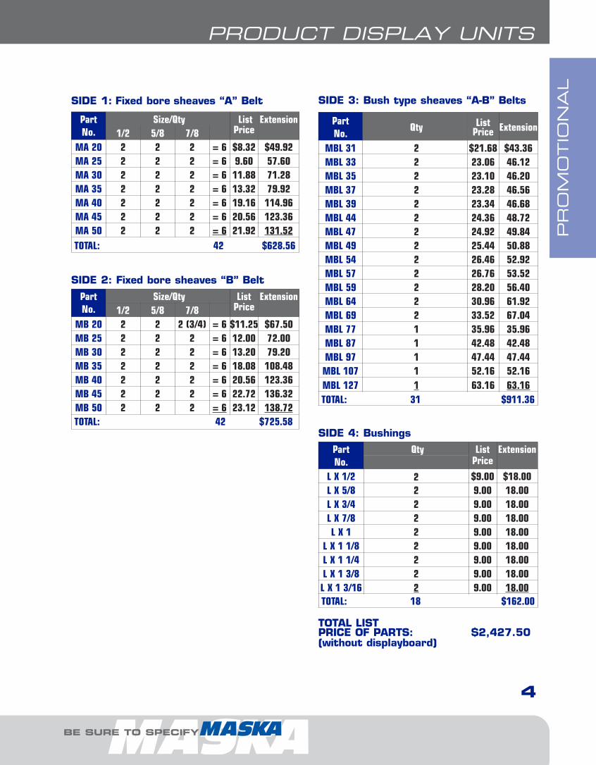
MA 20 2 2 2 = 6 $8.32 $49.92MA 25 2 2 2 = 6 9.60 57.60MA 30 2 2 2 = 6 11.88 71.28MA 35 2 2 2 = 6 13.32 79.92MA 40 2 2 2 = 6 19.16 114.96MA 45 2 2 2 = 6 20.56 123.36MA 50 2 2 2 = 6 21.92 131.52TOTAL: 42 $628.56
PartNo.
Size/Qty ListPrice
Extension1/2 5/8 7/8
MB 20 2 2 2 (3/4) = 6 $11.25 $67.50MB 25 2 2 2 = 6 12.00 72.00MB 30 2 2 2 = 6 13.20 79.20MB 35 2 2 2 = 6 18.08 108.48MB 40 2 2 2 = 6 20.56 123.36MB 45 2 2 2 = 6 22.72 136.32MB 50 2 2 2 = 6 23.12 138.72TOTAL: 42 $725.58
PartNo.
Qty ListPrice
Extension
L X 1/2 2 $9.00 $18.00L X 5/8 2 9.00 18.00L X 3/4 2 9.00 18.00L X 7/8 2 9.00 18.00L X 1 2 9.00 18.00
L X 1 1/8 2 9.00 18.00L X 1 1/4 2 9.00 18.00L X 1 3/8 2 9.00 18.00L X 1 3/16 2 9.00 18.00TOTAL: 18 $162.00
PartNo.
Qty ListPrice Extension
MBL 31 2 $21.68 $43.36MBL 33 2 23.06 46.12MBL 35 2 23.10 46.20MBL 37 2 23.28 46.56MBL 39 2 23.34 46.68MBL 44 2 24.36 48.72MBL 47 2 24.92 49.84MBL 49 2 25.44 50.88MBL 54 2 26.46 52.92MBL 57 2 26.76 53.52MBL 59 2 28.20 56.40MBL 64 2 30.96 61.92MBL 69 2 33.52 67.04MBL 77 1 35.96 35.96MBL 87 1 42.48 42.48MBL 97 1 47.44 47.44MBL 107 1 52.16 52.16MBL 127 1 63.16 63.16TOTAL: 31 $911.36
TOTAL LIST PRICE OF PARTS: $2,427.50(without displayboard)
SIDE 1: Fixed bore sheaves “A” Belt
SIDE 4: Bushings
SIDE 2: Fixed bore sheaves “B” Belt
SIDE 3: Bush type sheaves “A-B” Belts
ii-Promo.8.qxp 2009-03-19 14:04 Page 3
PR
OM
OTIO
NA
L WALL MODEL
5
PRODUCT DISPLAY UNITS
FOR DEPENDABLE DRIVE COMPONENTS, BE SURE TO SPECIFY
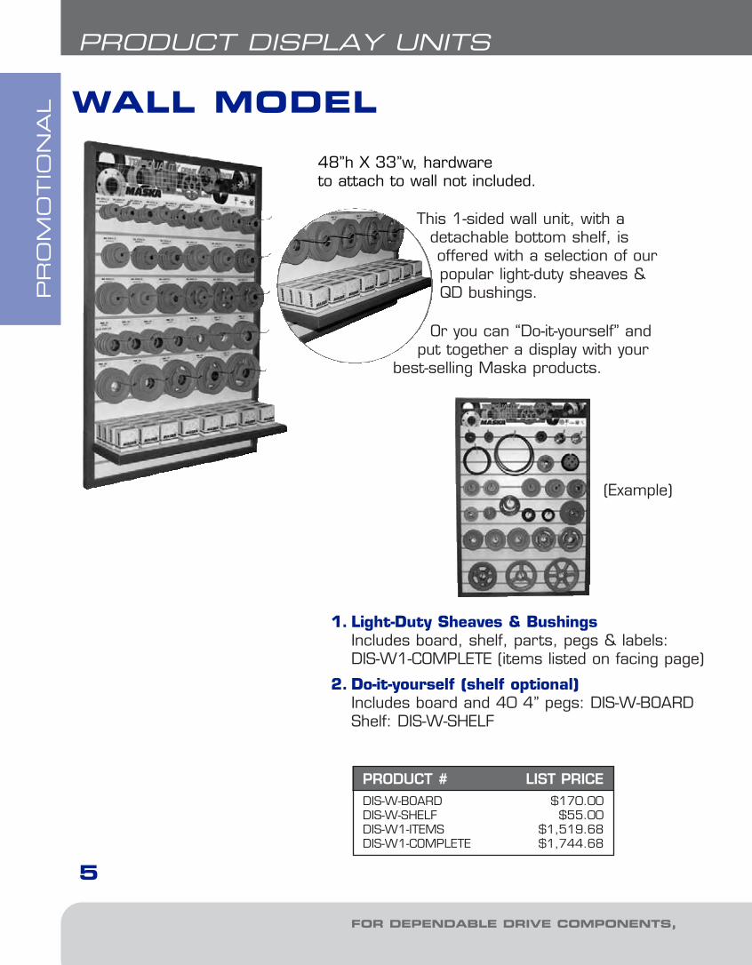
This 1-sided wall unit, with a detachable bottom shelf, isoffered with a selection of ourpopular light-duty sheaves &QD bushings.
Or you can “Do-it-yourself” andput together a display with your
best-selling Maska products.
1. Light-Duty Sheaves & BushingsIncludes board, shelf, parts, pegs & labels:DIS-W1-COMPLETE (items listed on facing page)
2. Do-it-yourself (shelf optional)Includes board and 40 4” pegs: DIS-W-BOARDShelf: DIS-W-SHELF
48”h X 33”w, hardware to attach to wall not included.
PRODUCT # LIST PRICEDIS-W-BOARD $170.00DIS-W-SHELF $55.00DIS-W1-ITEMS $1,519.68DIS-W1-COMPLETE $1,744.68
(Example)
ii-Promo.8.qxp 2009-03-19 14:04 Page 4

PR
OM
OTIO
NA
L
6
PRODUCT DISPLAY UNITS
BE SURE TO SPECIFY
age)
RD
Parts List
PartNo.
Size/Qty. ListPrice Total
11//22 55//88 77//88MA 20MA 25MA 30MA 35MA 40MA 45MA 50
2222222
2222222
2222222
= 6= 6= 6= 6= 6= 6= 6
42
$8.329.60
11.8813.3219.1620.5621.92
$49.9257.6071.2879.92
114.96123.36131.52
$628.56
FIXED BORE SHEAVES, “A” BELT
PartNo. Qty. List Price Total
MBL 31MBL 33MBL 35MBL 37MBL 39MBL 44MBL 47MBL 49MBL 54MBL 57MBL 59MBL 64
222222222222
24
$21.6823.0623.1023.2823.3424.3624.9225.4426.4626.7628.2030.96
$43.3646.1246.2046.5646.6848.7249.8450.8852.9253.5256.4061.92
$603.12
BUSH TYPE SHEAVES, “A-B” BELT
PartNo. Qty. List Price Total
L X 1/2L X 5/8L X 3/4L X 7/8L X 1
L X 1-1/8L X 1-1/4L X 1-3/8
44444444
32
$9.009.009.009.009.009.009.009.00
$36.0036.0036.0036.0036.0036.0036.0036.00
$288.00
QD BUSHINGS
TOTAL LIST PRICE OF WALL MODEL PARTS: $1,519.68
ii-Promo.8.qxp 2009-03-19 14:04 Page 5

PR
OM
OTIO
NA
L
FOR DEPENDABLE DRIVE COMPONENTS, BE SURE TO SPECIFY
V-BELT DRIVE ACCESSORIES
Indispensable tools for maintenance mechanics toensure efficient, cost-saving operations.
V-BELT TENSION METER
• Belts that are too loose will slip, causing excessive belt and sheave wear. • Sagging belts can snap during start-up or during peak loads.• Belts that are too tight can damage bearings.• Both situations reduce power transmission performance levels.
Proper tension and installation can lengthen belt life and lessen expensive downtime.
IMPORTANT REMINDER
• Improper belt tension, either too tight or tooloose, can result in belt drive problems. For critical drives, a manual verification is insufficient.
DID YOU KNOW THAT...Part No. 006347Call, or see your on-line price, for this item.
This indispensable maintenance tool is a handyway of checking belt tension on single strandbelts up to 1” wide within the ranges listed below.Scales are provided for checking the requiredforce and the belt deflection distance.
For use with all small V-belt and synchronousdrives.
Comes in a protective plastic tube with instruc-tions.
Force Range: 0-35 lbs. 0-15.9 kg.Tension Range: 0-560 lbs. 0-255 kg.
7
ii-Promo.8.qxp 2009-03-19 14:04 Page 6
PR
OM
OTIO
NA
L
BE SURE TO SPECIFY
V-BELT DRIVE ACCESSORIES
SHEAVE & BELT GAGE
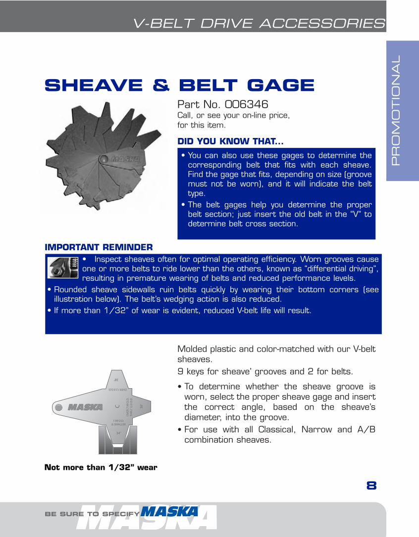
• Inspect sheaves often for optimal operating efficiency. Worn grooves causeone or more belts to ride lower than the others, known as “differential driving”,resulting in premature wearing of belts and reduced performance levels.
• Rounded sheave sidewalls ruin belts quickly by wearing their bottom corners (see illustration below). The belt’s wedging action is also reduced.
• If more than 1/32” of wear is evident, reduced V-belt life will result.
IMPORTANT REMINDER
• You can also use these gages to determine thecorresponding belt that fits with each sheave.Find the gage that fits, depending on size (groovemust not be worn), and it will indicate the belttype.
• The belt gages help you determine the properbelt section; just insert the old belt in the “V” todetermine belt cross section.
DID YOU KNOW THAT...
Part No. 006346Call, or see your on-line price, for this item.
Molded plastic and color-matched with our V-beltsheaves.9 keys for sheave’ grooves and 2 for belts.
• To determine whether the sheave groove isworn, select the proper sheave gage and insertthe correct angle, based on the sheave’s diameter, into the groove.
• For use with all Classical, Narrow and A/Bcombination sheaves.
Not more than 1/32” wear
8
ii-Promo.8.qxp 2009-03-19 14:04 Page 7
QD BUSHINGSB
USH
ING
S &
HU
BS
FOR DEPENDABLE DRIVE COMPONENTS, BE SURE TO SPECIFY
9
“QD” BUSHING
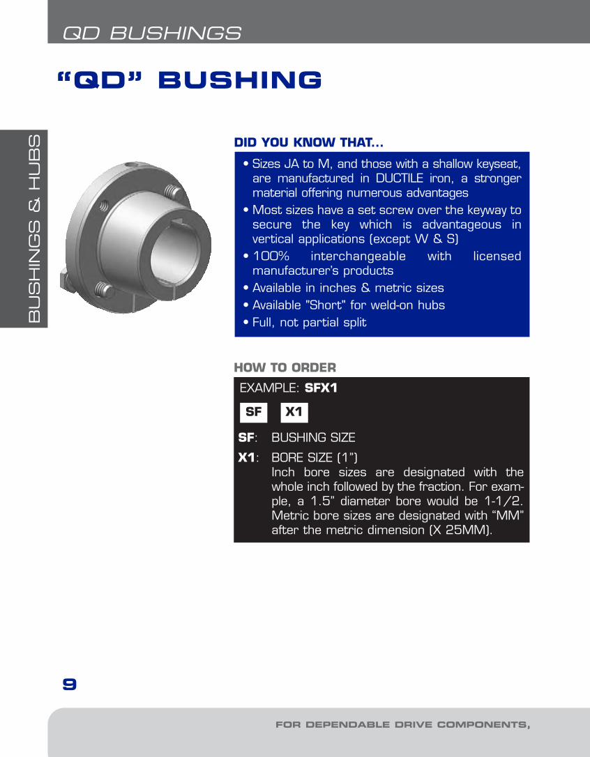
• Sizes JA to M, and those with a shallow keyseat,are manufactured in DUCTILE iron, a strongermaterial offering numerous advantages
• Most sizes have a set screw over the keyway tosecure the key which is advantageous in vertical applications (except W & S)
• 100% interchangeable with licensed manufacturer’s products
• Available in inches & metric sizes• Available "Short" for weld-on hubs• Full, not partial split
DID YOU KNOW THAT...
EXAMPLE: SFX1
SF X1
SF: BUSHING SIZE
X1: BORE SIZE (1”)Inch bore sizes are designated with thewhole inch followed by the fraction. For exam-ple, a 1.5” diameter bore would be 1-1/2.Metric bore sizes are designated with “MM”after the metric dimension (X 25MM).
HOW TO ORDER
1-Bushings1.10.qxp 2009-03-19 13:56 Page 2
BU
SH
ING
S &
HU
BS
BE SURE TO SPECIFY
BUSHINGSQD BUSHINGS
TAPERED, PRECISION FIT.
Precision machining of the tapered bore in the hub of the “QD” rim and the taperedmating surface of the bushing insures a snug, precision fit between rim and bushing. Tightening the cap screws draws the sheave up tight on the bushing -Maska “QD” Bushings and Sheaves are true running.
FULL - NOT PARTIAL SPLIT.
This feature, together with the tapered, precision fit of rim and bushing, enablesthe “QD” Bushing to compress evenly through the overall bushing length, thus gripping the shaft with tremendous pressure, the equivalent of a press fit on theshaft. And the full split makes it just as easy to install “QD” Sheaves on all standard size shafts as it is to install them on shafts which may be slightly oversized or slightly undersized.
EASY TO INSTALL, EASY TO REMOVE.
To install Maska “QD” Sheaves, the cap screws are used as pull-wrench only - noadditional leverage is necessary. To remove “QD” Sheaves, the cap screws aretaken out and used as jack screws. A few quick turns on each screw, and the tightgrip of the bushing on the shaft is easily broken.
SET SCREW OVER THE KEY.
Once the correct position of the “QD” Sheave on the shaft is determined, tighten-ing the set screw in the bushing flange down on the key will hold the bushing in thisposition while the pull-up bolts are tightened. This set screw holds the key in placeon the shaft during drive operation - an especially desirable feature on drives thathave vertical shafts facing down. Available on all “QD” bushings except W AND S.
FULLY INTERCHANGEABLE WITH OTHER “QD” BUSHINGS.
As in the case of Maska “QD” Sheaves, the “QD” Bushings also conform to standardized “QD” dimensions and sheave types. Because of this feature, any “QD”Stock Bushing may be interchanged with the same size bushing that other “QD”manufacturers produce.
10
“QD” bushings is a registred trademark and manufactured by Maska underlicense.
1-Bushings1.10.qxp 2009-03-19 13:56 Page 3
BU
SH
ING
S &
HU
BS
FOR DEPENDABLE DRIVE COMPONENTS, BE SURE TO SPECIFY
11
QD BUSHINGS
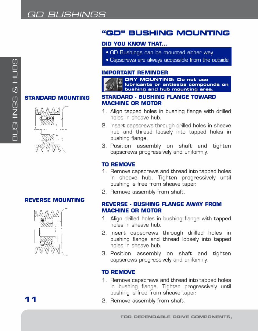
“QD” BUSHING MOUNTING
STANDARD - BUSHING FLANGE TOWARDMACHINE OR MOTOR1. Align tapped holes in bushing flange with drilled
holes in sheave hub.2. Insert capscrews through drilled holes in sheave
hub and thread loosely into tapped holes in bushing flange.
3. Position assembly on shaft and tighten capscrews progressively and uniformly.
TO REMOVE1. Remove capscrews and thread into tapped holes
in sheave hub. Tighten progressively until bushing is free from sheave taper.
2. Remove assembly from shaft.
REVERSE - BUSHING FLANGE AWAY FROMMACHINE OR MOTOR1. Align drilled holes in bushing flange with tapped
holes in sheave hub.2. Insert capscrews through drilled holes in
bushing flange and thread loosely into tappedholes in sheave hub.
3. Position assembly on shaft and tighten capscrews progressively and uniformly.
TO REMOVE1. Remove capscrews and thread into tapped holes
in bushing flange. Tighten progressively untilbushing is free from sheave taper.
2. Remove assembly from shaft.
STANDARD MOUNTING
REVERSE MOUNTING
• QD Bushings can be mounted either way• Capscrews are always accessible from the outside
DID YOU KNOW THAT...
DRY MOUNTING: Do not use lubricants or antiseize compounds onbushing and hub mounting area.
IMPORTANT REMINDER
1-Bushings1.10.qxp 2009-03-19 13:56 Page 4
BU
SH
ING
S &
HU
BS
BE SURE TO SPECIFY
BUSHINGS
12
QD BUSHINGS
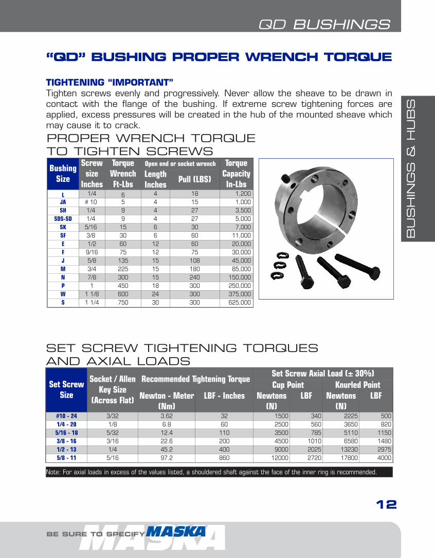
“QD” BUSHING PROPER WRENCH TORQUE
TIGHTENING “IMPORTANT”Tighten screws evenly and progressively. Never allow the sheave to be drawn incontact with the flange of the bushing. If extreme screw tightening forces areapplied, excess pressures will be created in the hub of the mounted sheave whichmay cause it to crack.
Set ScrewSize
Socket / AllenKey Size
(Across Flat)
Recommended Tightening TorqueSet Screw Axial Load (± 30%)Cup Point Knurled Point
Newton - Meter(Nm)
LBF - Inches Newtons(N)
LBF Newtons(N)
LBF
#10 - 24 3/32 3.62 32 1500 340 2225 5001/4 - 20 1/8 6.8 60 2500 560 3650 8205/16 - 18 5/32 12.4 110 3500 785 5110 11503/8 - 16 3/16 22.6 200 4500 1010 6580 14801/2 - 13 1/4 45.2 400 9000 2025 13230 29755/8 - 11 5/16 97.2 860 12000 2720 17800 4000
Note: For axial loads in excess of the values listed, a shouldered shaft against the face of the inner ring is recommended.
SET SCREW TIGHTENING TORQUES AND AXIAL LOADS
BushingSize
Screwsize
Inches
TorqueWrenchFt-Lbs
Open end or socket wrench TorqueCapacityIn-Lbs
LengthInches
Pull (LBS)
L 1/4 6 4 18 1,200JA # 10 5 4 15 1,000SH 1/4 9 4 27 3,500
SDS-SD 1/4 9 4 27 5,000SK 5/16 15 6 30 7,000SF 3/8 30 6 60 11,000E 1/2 60 12 60 20,000F 9/16 75 12 75 30,000J 5/8 135 15 108 45,000M 3/4 225 15 180 85,000N 7/8 300 15 240 150,000P 1 450 18 300 250,000W 1 1/8 600 24 300 375,000S 1 1/4 750 30 300 625,000
PROPER WRENCH TORQUETO TIGHTEN SCREWS
1-Bushings1.10.qxp 2009-03-19 13:56 Page 5

BU
SH
ING
S &
HU
BS
13
QD BUSHINGS
BushingSize
ListPrice
$
Dimensions - InchesCap Screws
RequiredNC Grade 5
SetScrew
Dimensions
Bore RangeApprox.WeightPoundsA B D E F G H L
BoltCircle
MMin. Max.
L* 9.00 11/32 1 5/8 2 1/2 1 29/32 3/16 3/32 1 11/32 2 2=1/4X7/8 10-24 UNC x 1/4” 3/8 1 1/2 0.7
JA* 10.90 5/16 1 3/8 2 11/16 5/8 13/64 9/64 1 1 21/32 3=10-24X1 10-24 UNC x 1/4” 1/2 1 1/4 0.4
SH* 14.90 3/8 1 7/8 2 11/16 7/8 3/4 1/4 1/8 1 1/4 2 1/4 3=1/4X1 3/8 1/4-20 UNC x 1/4” 1/2 1 11/16 0.9
SDS* 17.30 7/16 2 3/16 3 3/16 7/8 3/4 1/4 1/8 1 5/16 2 11/16 3=1/4X1 3/8 1/4-20 UNC x 1/4” 1/2 2 1.3
SD* 20.80 7/16 2 3/16 3 3/16 1 3/8 1 1/4 1/4 1/8 1 13/16 2 11/16 3=1/4X1 7/8 1/4-20 UNC x 1/4” 1/2 2 1.6
SK* 26.80 1/2 2 13/16 3 7/8 1 3/8 1 1/4 5/16 3/16 1 7/8 3 5/16 3=5/16X2 1/4-20 UNC x 1/4” 1/2 2 5/8 2.7
SF* 33.00 1/2 3 1/8 4 5/8 1 1/2 1 1/4 5/16 1/16 2 3 7/8 3=3/8X2 5/16-18 UNC x 3/8” 1/2 2 15/16 3.9
E* 69.20 3/4 3 27/32 6 1 7/8 1 5/8 5/16 1/16 2 5/8 5 3=1/2X2 3/4 3/8-16 UNC x 3/8” 7/8 3 1/2 8.5
F* 128.00 13/16 4 7/16 6 5/8 2 13/16 2 1/2 13/32 3/32 3 5/8 5 5/8 3=9/16X3 5/8 3/8-16 UNC x 3/8” 1 4 13.3
J* 160.00 1 5 5/32 7 1/4 3 1/2 3 3/16 13/32 3/32 4 1/2 6 1/4 3=5/8X4 1/2 3/8-16 UNC x 3/8” 1 7/16 4 1/2 20.8
M* 320.00 1 1/4 6 1/2 9 5 1/2 5 3/16 13/32 3/32 6 3/4 7 7/8 4=3/4X7 3/8-16 UNC x 1/2” 2 5 1/2 48.5
N* 560.00 1 1/2 7 10 6 5/8 6 1/4 9/16 3/16 8 1/8 8 1/2 4=7/8X8 1/2-13 UNC x 5/8” 2 3/4 6 62.1
P* 840.00 1 3/4 8 1/4 11 3/4 7 5/8 7 1/4 5/8 1/4 9 3/8 10 4=1X9 1/2 5/8-11 UNC x 1 1/4” 2 15/16 7 108.8
W 1480.00 2 10 7/16 15 9 3/8 9 5/8 1/4 11 3/8 12 3/4 4=1 1/8X11 1/2 None 4 1/4 8-1/2 218.9
S 3480.00 3 1/4 12 1/8 17 3/4 12 1/2 12 13/16 5/16 15 3/4 15 5=1 1/4X15 1/2 None 5 1/2 10 382.0
S-RB** 3132.00 3 1/4 12 1/8 17 3/4 12 1/2 12 13/16 5/16 15 3/4 15 5=1 1/4X15 1/2 None 5 1/2 10 382.0
* Standard with set screw over keyway. Refer to page 12 for Cap screw torque ratingsNote: Approx. weight in lbs. for an average size bore. ** RB = Rough bore
Bushing“L”
(“H” - CrossReference)
Bushing “JA to J”Inclusive
Bushing “M to W”Inclusive
Bushing “S” Taper 3/4”per FT on
Diameter - B -
“QD” BUSHINGS BORE AND KEYSEATDIMENSIONS
DIMENSIONS
FOR DEPENDABLE DRIVE COMPONENTS, BE SURE TO SPECIFY
1-Bushings1.10.qxp 2009-03-19 13:56 Page 6
BU
SH
ING
S &
HU
BS
14
QD BUSHINGS
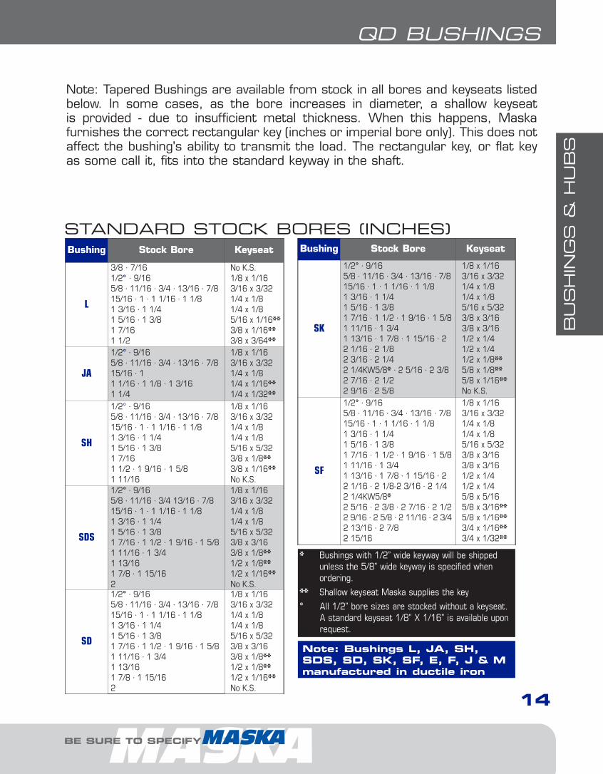
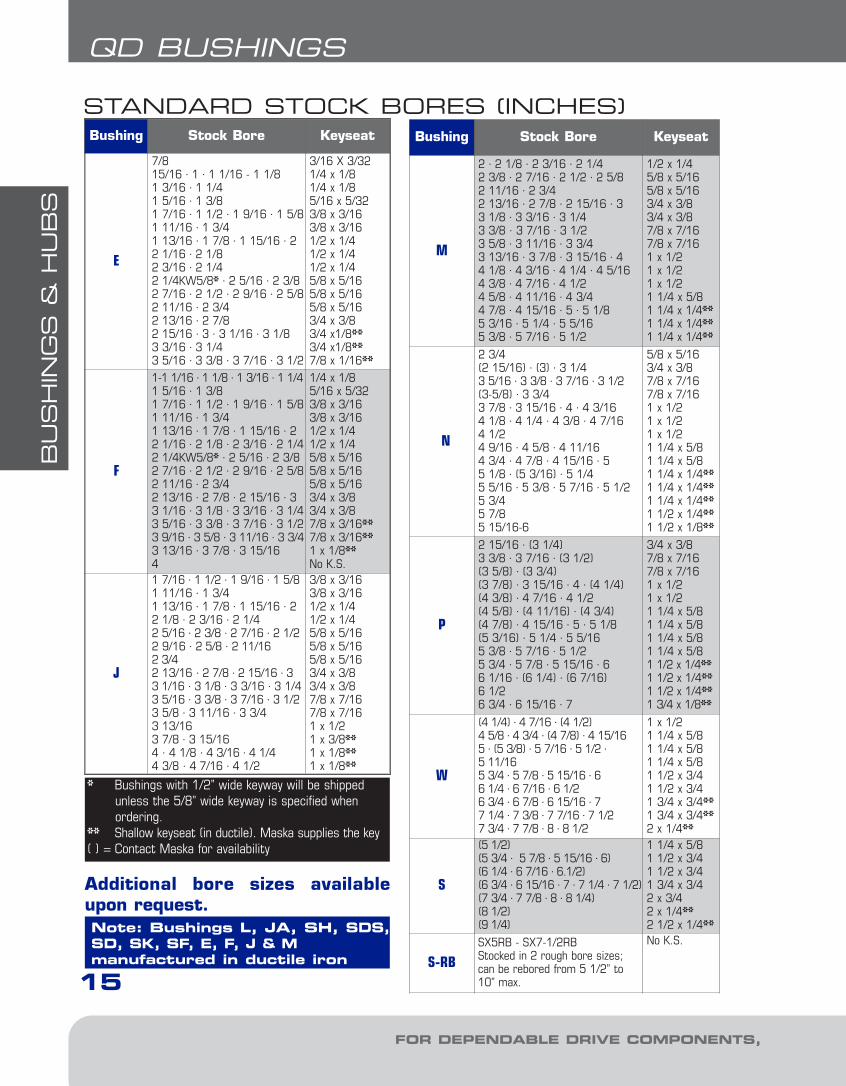
Note: Tapered Bushings are available from stock in all bores and keyseats listedbelow. In some cases, as the bore increases in diameter, a shallow keyseat is provided - due to insufficient metal thickness. When this happens, Maska furnishes the correct rectangular key (inches or imperial bore only). This does notaffect the bushing's ability to transmit the load. The rectangular key, or flat keyas some call it, fits into the standard keyway in the shaft.
Bushing Stock Bore Keyseat
SK
1/2° · 9/165/8 · 11/16 · 3/4 · 13/16 · 7/815/16 · 1 · 1 1/16 · 1 1/81 3/16 · 1 1/41 5/16 · 1 3/81 7/16 · 1 1/2 · 1 9/16 · 1 5/81 11/16 · 1 3/41 13/16 · 1 7/8 · 1 15/16 · 22 1/16 · 2 1/82 3/16 · 2 1/42 1/4KW5/8* · 2 5/16 · 2 3/82 7/16 · 2 1/22 9/16 · 2 5/8
1/8 x 1/163/16 x 3/321/4 x 1/81/4 x 1/85/16 x 5/323/8 x 3/163/8 x 3/161/2 x 1/41/2 x 1/41/2 x 1/8**5/8 x 1/8**5/8 x 1/16**No K.S.
SF
1/2° · 9/165/8 · 11/16 · 3/4 · 13/16 · 7/815/16 · 1 · 1 1/16 · 1 1/81 3/16 · 1 1/41 5/16 · 1 3/81 7/16 · 1 1/2 · 1 9/16 · 1 5/81 11/16 · 1 3/41 13/16 · 1 7/8 · 1 15/16 · 22 1/16 · 2 1/8-2 3/16 · 2 1/42 1/4KW5/8*2 5/16 · 2 3/8 · 2 7/16 · 2 1/22 9/16 · 2 5/8 · 2 11/16 · 2 3/42 13/16 · 2 7/82 15/16
1/8 x 1/163/16 x 3/321/4 x 1/81/4 x 1/85/16 x 5/323/8 x 3/163/8 x 3/161/2 x 1/41/2 x 1/45/8 x 5/165/8 x 3/16**5/8 x 1/16**3/4 x 1/16**3/4 x 1/32**
STANDARD STOCK BORES (INCHES)
* Bushings with 1/2” wide keyway will be shippedunless the 5/8” wide keyway is specified whenordering.
** Shallow keyseat Maska supplies the key
° All 1/2” bore sizes are stocked without a keyseat.A standard keyseat 1/8” X 1/16” is available uponrequest.
Bushing Stock Bore Keyseat
L
3/8 · 7/161/2° · 9/165/8 · 11/16 · 3/4 · 13/16 · 7/815/16 · 1 · 1 1/16 · 1 1/81 3/16 · 1 1/41 5/16 · 1 3/81 7/161 1/2
No K.S.1/8 x 1/163/16 x 3/321/4 x 1/81/4 x 1/85/16 x 1/16**3/8 x 1/16**3/8 x 3/64**
JA
1/2° · 9/165/8 · 11/16 · 3/4 · 13/16 · 7/815/16 · 11 1/16 · 1 1/8 · 1 3/161 1/4
1/8 x 1/163/16 x 3/321/4 x 1/81/4 x 1/16**1/4 x 1/32**
SH
1/2° · 9/165/8 · 11/16 · 3/4 · 13/16 · 7/815/16 · 1 · 1 1/16 · 1 1/81 3/16 · 1 1/41 5/16 · 1 3/81 7/161 1/2 · 1 9/16 · 1 5/81 11/16
1/8 x 1/163/16 x 3/321/4 x 1/81/4 x 1/85/16 x 5/323/8 x 1/8**3/8 x 1/16**No K.S.
SDS
1/2° · 9/165/8 · 11/16 · 3/4 13/16 · 7/815/16 · 1 · 1 1/16 · 1 1/81 3/16 · 1 1/41 5/16 · 1 3/81 7/16 · 1 1/2 · 1 9/16 · 1 5/81 11/16 · 1 3/41 13/161 7/8 · 1 15/162
1/8 x 1/163/16 x 3/321/4 x 1/81/4 x 1/85/16 x 5/323/8 x 3/163/8 x 1/8**1/2 x 1/8**1/2 x 1/16**No K.S.
SD
1/2° · 9/165/8 · 11/16 · 3/4 · 13/16 · 7/815/16 · 1 · 1 1/16 · 1 1/81 3/16 · 1 1/41 5/16 · 1 3/81 7/16 · 1 1/2 · 1 9/16 · 1 5/81 11/16 · 1 3/41 13/161 7/8 · 1 15/162
1/8 x 1/163/16 x 3/321/4 x 1/81/4 x 1/85/16 x 5/323/8 x 3/163/8 x 1/8**1/2 x 1/8**1/2 x 1/16**No K.S.
Note: Bushings L, JA, SH,SDS, SD, SK, SF, E, F, J & Mmanufactured in ductile iron
BE SURE TO SPECIFY
1-Bushings1.10.qxp 2009-03-19 13:56 Page 7
BU
SH
ING
S &
HU
BS
15
QD BUSHINGS
Bushing Stock Bore Keyseat
E
7/815/16 · 1 · 1 1/16 - 1 1/81 3/16 · 1 1/41 5/16 · 1 3/81 7/16 · 1 1/2 · 1 9/16 · 1 5/81 11/16 · 1 3/41 13/16 · 1 7/8 · 1 15/16 · 22 1/16 · 2 1/82 3/16 · 2 1/42 1/4KW5/8* · 2 5/16 · 2 3/82 7/16 · 2 1/2 · 2 9/16 · 2 5/82 11/16 · 2 3/42 13/16 · 2 7/82 15/16 · 3 · 3 1/16 · 3 1/83 3/16 · 3 1/43 5/16 · 3 3/8 · 3 7/16 · 3 1/2
3/16 X 3/321/4 x 1/81/4 x 1/85/16 x 5/323/8 x 3/163/8 x 3/161/2 x 1/41/2 x 1/41/2 x 1/45/8 x 5/165/8 x 5/165/8 x 5/163/4 x 3/83/4 x1/8**3/4 x1/8**7/8 x 1/16**
F
1-1 1/16 · 1 1/8 · 1 3/16 · 1 1/41 5/16 · 1 3/81 7/16 · 1 1/2 · 1 9/16 · 1 5/81 11/16 · 1 3/41 13/16 · 1 7/8 · 1 15/16 · 22 1/16 · 2 1/8 · 2 3/16 · 2 1/42 1/4KW5/8* · 2 5/16 · 2 3/82 7/16 · 2 1/2 · 2 9/16 · 2 5/82 11/16 · 2 3/42 13/16 · 2 7/8 · 2 15/16 · 33 1/16 · 3 1/8 · 3 3/16 · 3 1/43 5/16 · 3 3/8 · 3 7/16 · 3 1/23 9/16 · 3 5/8 · 3 11/16 · 3 3/43 13/16 · 3 7/8 · 3 15/164
1/4 x 1/85/16 x 5/323/8 x 3/163/8 x 3/161/2 x 1/41/2 x 1/45/8 x 5/165/8 x 5/165/8 x 5/163/4 x 3/83/4 x 3/87/8 x 3/16**7/8 x 3/16**1 x 1/8**No K.S.
J
1 7/16 · 1 1/2 · 1 9/16 · 1 5/81 11/16 · 1 3/41 13/16 · 1 7/8 · 1 15/16 · 22 1/8 · 2 3/16 · 2 1/42 5/16 · 2 3/8 · 2 7/16 · 2 1/22 9/16 · 2 5/8 · 2 11/162 3/42 13/16 · 2 7/8 · 2 15/16 · 33 1/16 · 3 1/8 · 3 3/16 · 3 1/43 5/16 · 3 3/8 · 3 7/16 · 3 1/23 5/8 · 3 11/16 · 3 3/43 13/163 7/8 · 3 15/164 · 4 1/8 · 4 3/16 · 4 1/44 3/8 · 4 7/16 · 4 1/2
3/8 x 3/163/8 x 3/161/2 x 1/41/2 x 1/45/8 x 5/165/8 x 5/165/8 x 5/163/4 x 3/83/4 x 3/87/8 x 7/167/8 x 7/161 x 1/21 x 3/8**1 x 1/8**1 x 1/8**
Bushing Stock Bore Keyseat
M
2 · 2 1/8 · 2 3/16 · 2 1/42 3/8 · 2 7/16 · 2 1/2 · 2 5/82 11/16 · 2 3/42 13/16 · 2 7/8 · 2 15/16 · 33 1/8 · 3 3/16 · 3 1/43 3/8 · 3 7/16 · 3 1/23 5/8 · 3 11/16 · 3 3/43 13/16 · 3 7/8 · 3 15/16 · 44 1/8 · 4 3/16 · 4 1/4 · 4 5/164 3/8 · 4 7/16 · 4 1/24 5/8 · 4 11/16 · 4 3/44 7/8 · 4 15/16 · 5 · 5 1/85 3/16 · 5 1/4 · 5 5/165 3/8 · 5 7/16 · 5 1/2
1/2 x 1/45/8 x 5/165/8 x 5/163/4 x 3/83/4 x 3/87/8 x 7/167/8 x 7/161 x 1/21 x 1/21 x 1/21 1/4 x 5/81 1/4 x 1/4**1 1/4 x 1/4**1 1/4 x 1/4**
N
2 3/4(2 15/16) · (3) · 3 1/43 5/16 · 3 3/8 · 3 7/16 · 3 1/2(3-5/8) · 3 3/43 7/8 · 3 15/16 · 4 · 4 3/164 1/8 · 4 1/4 · 4 3/8 · 4 7/164 1/24 9/16 · 4 5/8 · 4 11/164 3/4 · 4 7/8 · 4 15/16 · 55 1/8 · (5 3/16) · 5 1/45 5/16 · 5 3/8 · 5 7/16 · 5 1/25 3/45 7/85 15/16-6
5/8 x 5/163/4 x 3/87/8 x 7/167/8 x 7/161 x 1/21 x 1/21 x 1/21 1/4 x 5/81 1/4 x 5/81 1/4 x 1/4**1 1/4 x 1/4**1 1/4 x 1/4**1 1/2 x 1/4**1 1/2 x 1/8**
P
2 15/16 · (3 1/4)3 3/8 · 3 7/16 · (3 1/2)(3 5/8) · (3 3/4)(3 7/8) · 3 15/16 · 4 · (4 1/4)(4 3/8) · 4 7/16 · 4 1/2(4 5/8) · (4 11/16) · (4 3/4)(4 7/8) · 4 15/16 · 5 · 5 1/8(5 3/16) · 5 1/4 · 5 5/165 3/8 · 5 7/16 · 5 1/25 3/4 · 5 7/8 · 5 15/16 · 66 1/16 · (6 1/4) · (6 7/16)6 1/26 3/4 · 6 15/16 · 7
3/4 x 3/87/8 x 7/167/8 x 7/161 x 1/21 x 1/21 1/4 x 5/81 1/4 x 5/81 1/4 x 5/81 1/4 x 5/81 1/2 x 1/4**1 1/2 x 1/4**1 1/2 x 1/4**1 3/4 x 1/8**
W
(4 1/4) · 4 7/16 · (4 1/2)4 5/8 · 4 3/4 · (4 7/8) · 4 15/165 · (5 3/8) · 5 7/16 · 5 1/2 ·5 11/165 3/4 · 5 7/8 · 5 15/16 · 66 1/4 · 6 7/16 · 6 1/26 3/4 · 6 7/8 · 6 15/16 · 77 1/4 · 7 3/8 · 7 7/16 · 7 1/27 3/4 · 7 7/8 · 8 · 8 1/2
1 x 1/21 1/4 x 5/81 1/4 x 5/81 1/4 x 5/81 1/2 x 3/41 1/2 x 3/41 3/4 x 3/4**1 3/4 x 3/4**2 x 1/4**
S
(5 1/2)(5 3/4 · 5 7/8 · 5 15/16 · 6)(6 1/4 · 6 7/16 · 6.1/2)(6 3/4 · 6 15/16 · 7 · 7 1/4 · 7 1/2)(7 3/4 · 7 7/8 · 8 · 8 1/4)(8 1/2)(9 1/4)
1 1/4 x 5/81 1/2 x 3/41 1/2 x 3/41 3/4 x 3/42 x 3/42 x 1/4**2 1/2 x 1/4**
S-RBSX5RB - SX7-1/2RBStocked in 2 rough bore sizes; can be rebored from 5 1/2” to 10” max.
No K.S.
STANDARD STOCK BORES (INCHES)
Note: Bushings L, JA, SH, SDS,SD, SK, SF, E, F, J & Mmanufactured in ductile iron
Additional bore sizes availableupon request.
FOR DEPENDABLE DRIVE COMPONENTS, BE SURE TO SPECIFY
* Bushings with 1/2” wide keyway will be shippedunless the 5/8” wide keyway is specified whenordering.
** Shallow keyseat (in ductile). Maska supplies the key( ) = Contact Maska for availability
1-Bushings1.10.qxp 2009-03-19 13:56 Page 8

BU
SH
ING
S &
HU
BS
16
QD BUSHINGS
Bushing Stock Bore Key
L
14 · 15 · 1618 · 19 · 20 · 2224 · 25 · 28 · 303235 · (38)
5 x 56 x 68 x 710 x 810 X 6**
JA
14 · 15 · 1618 · 19 · 20 · 2224 · 2528
5 x 56 x 68 x 6**8 x 5**
SH
14 · 15 · 1618 · 19 · 20 · 2224 · 25 · 28 · 3032 · 353840
5 x 56 x 68 x 710 x 810 x 7**No K.S.
SDS
14 · 15 · 1618 · 19 · 20 · 2224 · 25 · 28 · 3032 · 35 · 3840 · 42
5 x 56 x 68 x 710 x 812 x 8
SD
14 · 15 · 1618 · 19 · 20 · 2224 · 25 · 28 · 3032 · 35 · 3840 · 42
5 x 56 x 68 x 710 x 812 x 8
SK
14 · 15 · 1618 · 19 · 20 · 2224 · 25 · 28 · 3032 · 35 · 3840 · 4245 · 48 · 505560
5 x 56 x 68 x 710 x 812 x 814 x 916 x 1018 x 9**
SF
25 · 28 · 3032 · 35 · 3840 · 4245 · 48 · 505560 · 65
8 x 710 x 812 x 814 x 916 x 1018 x 11
STANDARD STOCK BORES (MILLIMETERS)Bushing Stock Bore Key
E
35 · 3840 · 4245 · 48 · 505560 · 6570 · 7580
10 x 812 x 814 x 916 x 1018 x 1120 x 1222 x 14
F
45 · 48 · 505560 · 6570 · 7580 · 8590 · 95100
14 x 916 x 1018 x 1120 x 1222 x 1425 x 14No K.S.
J
505560 · 6570 · 7580 · 8590 · 95100(110)(115)
14 x 916 x 1018 x 1120 x 1222 x 1425 x 1428 x 1628 x 15**28 x 10.9**
M90100115 · 120
25 x 1428 x 1632 x 18
N90100 · 110120
25 x 1428 x 1632 x 18
P 130(150)
32 x 1836 x 20
Additional bore sizes availableupon request.
Note: Bushings L, JA, SH,SDS, SD, SK, SF, E, F, J & Mmanufactured in ductile iron
** Shallow keyseat (in ductile)( ) = Contact Maska for availability
BE SURE TO SPECIFY
Note: In metric bores, a key is not supplied for shallow keyway. The metric systemdoes not refer to keyseat or keyway dimensions as does the English system;instead, dimensions are given for the key itself. For nominal diameter up to 22 mm, the key is square in shape. For nominal diameter over 22 mm, the key isrectangular in shape. This meets ISO standards.
1-Bushings1.10.qxp 2009-03-19 13:56 Page 9

BU
SH
ING
S &
HU
BS
17
TAPER-LOCK BUSHINGS
FOR DEPENDABLE DRIVE COMPONENTS, BE SURE TO SPECIFY
TAPER-LOCK BUSHINGS
To Install:
1. Clean all parts of the bushing and bore of hubthus removing any oil, lacquer or dirt. Installbushing in hub and match half holes to makecomplete holes (each complete hole will bethreaded on one side only).
2. Oil thread and either the end of set screws orunder the head of the cap screws. Install screwsloosely in holes that are threaded on the hubside.
EXAMPLE: 2012X1-3/8
2012 X1-3/8
2012: BUSHING SIZE
The Taper-Lock bushing size is definedby 4 digits representing two numbers.The first two digits represent the maximum bore size and the secondtwo digits represent the bushinglength. For example, product number1008 has a max. bore of 1.0” and atotal length of 0.8”
X1-3/8: BORE SIZE (1-3/8”)
Bore s i ze : I nch bore s i zes aredesignated with the whole inch followedby the fraction. For example, a 1.5”diameter bore would be 1-1/2. Metricbore sizes are designated with “MM”after the metric dimension (X 25MM).
HOW TO ORDER
• Available in inches & millimeters• Flush mounting• Sizes 1008 – 5050
DID YOU KNOW THAT...
1-Bushings1.10.qxp 2009-03-19 13:56 Page 10

BU
SH
ING
S &
HU
BS
18
BE SURE TO SPECIFY
TAPER-LOCK BUSHINGS
Bushing No. SCREWSWrench torque(Pounds-Inches)
Wrench torque(Pounds-Feet)
1008, 1108 1/4” Set Screws 55 4.5
1210, 1215, 1310 3/8” Set Screws 175 14.5
1610, 1615 3/8” Set Screws 175 14.5
2012 7/16” Set Screws 280 23.0
2517, 2525 1/2” Set Screws 430 36.0
3020, 3030 5/8” Set Screws 800 67.0
3535 1/2” Cap Screws 1,000 83.0
4040 5/8” Cap Screws 1,700 142.0
4545 3/4” Cap Screws 2,450 204.0
5050 7/8” Cap Screws 3,100 258.0
PROPER WRENCH TORQUE TOTIGHTEN SCREWS
3. Make sure that the bushing is free in the hub. Slip assembly onto shaft andalign in the desired position.
4. Tighten screws evenly and alternately until the part has tightened. (See tablebelow for wrench torque)
5. Hammer with a block or sleeve the large end of the bushing. Re-tightenscrews using the correct torque. Repeat this procedure until the screws nolonger turn. Fill remaining holes with grease to prevent dirt buildup.
To Remove:
1. Remove all screws. Oil thread and either the end of set screws or under thehead of cap screws.
2. Insert screws in hole(s) that are threaded on the bushing side (see diagramon following page). Note that there will be one extra screw left over.
3. Tighten screws alternately until the bushing is loose in the hub. It may be necessary to tap on the hub to loosen the bushing.
1-Bushings1.10.qxp 2009-03-19 13:56 Page 11
BU
SH
ING
S &
HU
BS
19
TAPER-LOCK BUSHINGS
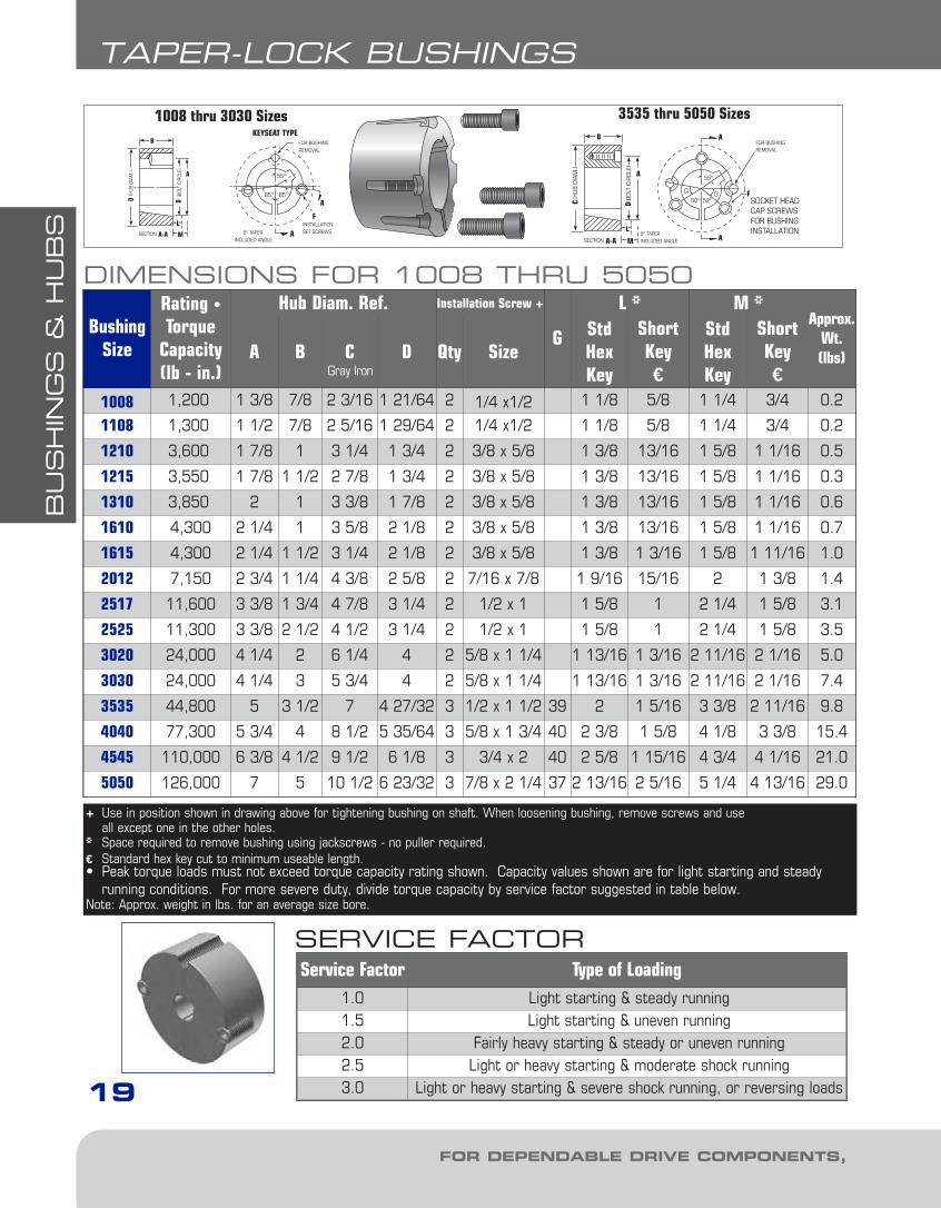
DIMENSIONS FOR 1008 THRU 5050
BushingSize
Rating •Torque
Capacity(lb - in.)
Hub Diam. Ref. Installation Screw +
G
L * M *Approx.
Wt.(lbs)A B C D Qty Size
StdHexKey
ShortKey€
StdHexKey
ShortKey€
1008 1,200 1 3/8 7/8 2 3/16 1 21/64 2 1/4 x1/2 1 1/8 5/8 1 1/4 3/4 0.2
1108 1,300 1 1/2 7/8 2 5/16 1 29/64 2 1/4 x1/2 1 1/8 5/8 1 1/4 3/4 0.2
1210 3,600 1 7/8 1 3 1/4 1 3/4 2 3/8 x 5/8 1 3/8 13/16 1 5/8 1 1/16 0.5
1215 3,550 1 7/8 1 1/2 2 7/8 1 3/4 2 3/8 x 5/8 1 3/8 13/16 1 5/8 1 1/16 0.3
1310 3,850 2 1 3 3/8 1 7/8 2 3/8 x 5/8 1 3/8 13/16 1 5/8 1 1/16 0.6
1610 4,300 2 1/4 1 3 5/8 2 1/8 2 3/8 x 5/8 1 3/8 13/16 1 5/8 1 1/16 0.7
1615 4,300 2 1/4 1 1/2 3 1/4 2 1/8 2 3/8 x 5/8 1 3/8 1 3/16 1 5/8 1 11/16 1.0
2012 7,150 2 3/4 1 1/4 4 3/8 2 5/8 2 7/16 x 7/8 1 9/16 15/16 2 1 3/8 1.4
2517 11,600 3 3/8 1 3/4 4 7/8 3 1/4 2 1/2 x 1 1 5/8 1 2 1/4 1 5/8 3.1
2525 11,300 3 3/8 2 1/2 4 1/2 3 1/4 2 1/2 x 1 1 5/8 1 2 1/4 1 5/8 3.5
3020 24,000 4 1/4 2 6 1/4 4 2 5/8 x 1 1/4 1 13/16 1 3/16 2 11/16 2 1/16 5.0
3030 24,000 4 1/4 3 5 3/4 4 2 5/8 x 1 1/4 1 13/16 1 3/16 2 11/16 2 1/16 7.4
3535 44,800 5 3 1/2 7 4 27/32 3 1/2 x 1 1/2 39 2 1 5/16 3 3/8 2 11/16 9.8
4040 77,300 5 3/4 4 8 1/2 5 35/64 3 5/8 x 1 3/4 40 2 3/8 1 5/8 4 1/8 3 3/8 15.4
4545 110,000 6 3/8 4 1/2 9 1/2 6 1/8 3 3/4 x 2 40 2 5/8 1 15/16 4 3/4 4 1/16 21.0
5050 126,000 7 5 10 1/2 6 23/32 3 7/8 x 2 1/4 37 2 13/16 2 5/16 5 1/4 4 13/16 29.0
+ Use in position shown in drawing above for tightening bushing on shaft. When loosening bushing, remove screws and useall except one in the other holes.
* Space required to remove bushing using jackscrews - no puller required.€ Standard hex key cut to minimum useable length.• Peak torque loads must not exceed torque capacity rating shown. Capacity values shown are for light starting and steady
running conditions. For more severe duty, divide torque capacity by service factor suggested in table below.Note: Approx. weight in lbs. for an average size bore.
Gray Iron
FOR DEPENDABLE DRIVE COMPONENTS, BE SURE TO SPECIFY
Service Factor Type of Loading1.0 Light starting & steady running1.5 Light starting & uneven running2.0 Fairly heavy starting & steady or uneven running2.5 Light or heavy starting & moderate shock running3.0 Light or heavy starting & severe shock running, or reversing loads
SERVICE FACTOR
1-Bushings1.10.qxp 2009-03-19 13:56 Page 12
BU
SH
ING
S &
HU
BS
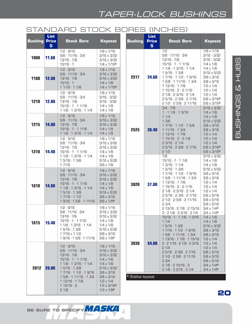
BushingListPrice
$Stock Bore Keyseat
1008 11.60
1/2 · 9/165/8 · 11/16 · 3/413/16 · 7/815/16 · 1
1/8 x 1/163/16 x 3/323/16 x 3/321/4 x 1/16*
1108 12.00
1/2 · 9/165/8 · 11/16 · 3/413/16 · 7/815/16 · 11 1/16 · 1 1/8
1/8 x 1/163/16 x 3/323/16 x 3/321/4 x 1/81/4 x 1/16*
1210 12.80
1/2 · 9/165/8 · 11/16 · 3/413/16 · 7/815/16 · 1 · 1 1/161 1/8 · 1 3/16 · 1 1/4
1/8 x 1/163/16 - 3/323/16 - 3/321/4 x 1/81/4 x 1/8
1215 14.00
1/2 · 9/165/8 · 11/16 · 3/413/16 · 7/815/16 · 1 · 1 1/161 1/8 · 1 3/16 · 1 1/4
1/8 x 1/163/16 x 3/323/16 x 3/321/4 x 1/81/4 x 1/8
1310 14.40
1/2 · 9/165/8 · 11/16 · 3/413/16 · 7/815/16 · 1 · 1 1/161 1/8 · 1 3/16 · 1 1/41 5/16 · 1 3/81 7/16
1/8 x 1/163/16 x 3/323/16 x 3/321/4 x 1/81/4 x 1/85/16 x 5/323/8 x 1/8
1610 14.80
1/2 · 9/165/8 · 11/16 · 3/413/16 · 7/815/16 · 1 · 1 1/161 1/8 · 1 3/16 · 1 1/41 5/16 · 1 3/81 7/16 · 1 1/21 9/16 · 1 5/8 · 1 11/16
1/8 x 1/163/16 x 3/323/16 x 3/321/4 x 1/81/4 x 1/85/16 x 5/323/8 x 3/163/8 x 1/8*
1615 15.40
1/2 · 9/165/8 · 11/16 · 3/413/16 · 7/815/16 · 1 · 1 1/161 1/8 · 1 3/16 · 1 1/41 5/16 · 1 3/81 7/16 x 1 1/21 9/16 · 1 5/8 · 1 11/16
1/8 x 1/163/16 x 3/323/16 x 3/321/4 x 1/81/4 x 1/85/16 x 5/323/8 x 3/163/8 x 1/8*
2012 20.00
1/2 · 9/165/8 · 11/16 · 3/413/16 · 7/815/16 · 1 · 1 1/161 1/8 · 1 3/16 · 1 1/41 5/16 · 1 3/81 7/16 · 1 1/2 · 1 9/161 5/8 · 1 11/16 · 1 3/41 13/16 · 1 7/8 1 15/16 · 22 1/8
1/8 x 1/163/16 x 3/323/16 x 3/321/4 x 1/81/4 x 1/85/16 x 5/323/8 x 3/163/8 x 3/161/2 x 1/41/2 x 3/16*1/2 x 1/8*
STANDARD STOCK BORES (INCHES)
BushingListPrice
$Stock Bore Keyseat
2517 24.60
1/25/8 · 11/16 · 3/413/16 · 7/815/16 · 1 · 1 1/161 1/8 · 1 3/16 · 1 1/41 5/16 · 1 3/81 7/16 · 1 1/2 · 1 9/161 5/8 · 1 11/16 · 1 3/41 13/16 · 1 7/81 15/16 · 2 · 2 1/162 1/8 · 2 3/16 · 2 1/42 5/16 · 2 3/8 · 2 7/162 1/2 · 2 5/8 · 2 11/16
1/8 x 1/163/16 - 3/323/16 - 3/321/4 x 1/81/4 x 1/85/16 x 5/323/8 x 3/163/8 x 3/161/2 x 1/41/2 x 1/41/2 x 1/45/8 x 3/16*5/8 x 3/16*
2525 36.40
3/4 · 7/81 · 1 1/8 · 1 3/161 1/41 3/81 7/16 · 1 1/2 · 1 5/81 11/16 · 1 3/41 13/16 · 1 7/81 15/16 · 2 · 2 1/82 3/16 · 2 1/42 5/16 · 2 3/8 · 2 7/162 1/2
3/16 x 3/321/4 x 1/81/4 x 1/85/16 x 5/323/8 x 3/163/8 x 3/161/2 x 1/41/2 x 1/41/2 x 1/45/8 x 3/16*5/8 x 3/16*
3020 37.00
7/815/16 · 1 · 1 1/81 3/16 · 1 1/41 5/16 · 1 3/81 7/16 · 1 1/2 · 1 9/161 5/8 · 1 11/16 · 1 3/41 13/16 · 1 7/81 15/16 · 2 · 2 1/162 1/8 · 2 3/16 · 2 1/42 5/16 · 2 3/8 · 2 7/162 1/2 · 2 5/8 · 2 11/162 3/42 13/16 · 2 7/8 · 2 15/163 · 3 1/8 · 3 3/16 · 3 1/4
3/16 x 3/321/4 x 1/81/4 x 1/85/16 x 5/323/8 x 3/163/8 x 3/161/2 x 1/41/2 x 1/41/2 x 1/45/8 x 5/165/8 x 5/165/8 x 5/163/4 x 1/4*3/4 x 1/4*
3030 54.00
15/16 · 1 · 1 1/8 · 1 3/161 1/41 5/16 · 1 3/81 7/16 · 1 1/2 · 1 9/161 5/8 · 1 11/16 · 1 3/41 13/16 · 1 7/8 · 1 15/162 · 2 1/16 · 2 1/8 · 2 3/162 1/42 5/16 · 2 3/8 · 2 7/162 1/2 · 2 5/8 · 2 11/162 3/42 7/8 · 2 15/16 · 33 1/8 · 3 3/16 · 3 1/4
1/4 x 1/81/4 x 1/85/16 x 3/323/8 x 3/163/8 x 3/161/2 x 1/41/2 x 1/41/2 x 1/45/8 x 5/165/8 x 5/165/8 x 5/163/4 x 1/4*3/4 x 1/4*
* Shallow keyseat
BE SURE TO SPECIFY
TAPER-LOCK BUSHINGS
20
1-Bushings1.10.qxp 2009-03-19 13:56 Page 13

BU
SH
ING
S &
HU
BS
21
TAPER-LOCK BUSHINGS
FOR DEPENDABLE DRIVE COMPONENTS, BE SURE TO SPECIFY
BushingListPrice
$Stock Bore Keyseat
3535 76.00
1 3/16 · 1 1/41 3/81 7/16 · 1 1/2 · 1 5/81 11/16 · 1 3/41 7/8 · 1 15/16 · 22 1/8 · 2 3/16 · 2 1/42 3/8 · 2 7/16 · 2 1/22 5/8 · 2 11/16 · 2 3/42 7/8 · 2 15/16 · 33 1/8 · 3 3/16 · 3 1/43 5/16 · 3 3/8 · 3 7/163 1/2 · 3 5/8 · 3 11/163 3/43 7/8 · 3 15/16
1/4 x 1/85/16 x 5/323/8 x 3/163/8 x 3/161/2 x 1/41/2 x 1/45/8 x 5/165/8 x 5/163/4 x 3/83/4 x 3/87/8 x 1/4*7/8 x 1/4*7/8 x 1/4*1 x 1/4*
4040 122.00
1 7/16 · 1 1/2 · 1 5/81 11/16 · 1 3/41 7/8 · 1 15/16 · 22 1/8 · 2 3/16 · 2 1/42 3/8 · 2 7/16 · 2 1/22 5/8 · 2 11/16 · 2 3/42 7/8 · 2 15/16 · 3 · 3 1/83 3/16 · 3 1/43 3/8 · 3 7/16 · 3 1/23 5/83 11/16 · 3 3/43 7/8 · 3 15/16 · 44 1/8 · 4 3/16 · 4 1/44 3/8 · 4 7/16
3/8 x 3/163/8 x 3/161/2 x 1/41/2 x 1/45/8 x 5/165/8 x 5/163/4 x 3/83/4 x 3/87/8 x 7/167/8 x 7/167/8 x 1/4*1 x 1/4*1 x 1/4*1 x 1/4*
4545 152.00
1 15/16 · 2 · 2 3/162 3/8 · 2 7/16 · 2 5/82 3/42 7/8 · 2 15/16 · 33 1/8 · 3 3/16 · 3 1/43 3/8 · 3 7/16 · 3 1/23 5/8 · 3 3/43 7/8 · 3 15/16 · 44 1/8 · 4 3/16 · 4 1/44 3/8 · 4 7/16 · 4 1/24 3/4 · 4 7/8 · 4 15/16
1/2 x 1/45/8 x 5/165/8 x 5/163/4 x 3/83/4 x 3/87/8 x 7/167/8 x 7/161 x 1/21 x 1/21 x 1/4*1 1/4 x 1/4*
5050 246.00
2 7/16 · 2 11/162 15/163 3/8 · 3 7/16 · 3 5/83 7/8 · 3 15/16 · 44 1/4 · 4 3/8 · 4 7/164 1/24 7/8 · 4 15/16 · 5
5/8 x 5/163/4 x 3/87/8 x 7/161 x 1/21 x 1/21 x 1/21 1/4 x 7/16*
STANDARD STOCK BORES (INCHES)
* Shallow keyseat
1-Bushings1.10.qxp 2009-03-19 13:56 Page 14

BU
SH
ING
S &
HU
BS
BE SURE TO SPECIFY
TAPER-LOCK BUSHINGS
Bushing ListPrice $ Stock Bore Key
1008 11.6014 · 1618 · 19 · 20 · 22(24)
5 x 56 x 68 x 7
1108 12.00
(12)14 · (15) · 1618 · 19 · 20 · 2224 · 25
4 x 45 x 56 x 68 x 7
1210 12.80
14 · (15) · 1618 · 19 · 20 · 2224 · 25 · 28 · 30(32)
5 x 56 x 68 x 7
10 x 8
1215 14.00
1619 · 2024 · 25 · 28 · 3032
5 x 56 x 68 x 7
10 x 8
1310 14.40
14 · 1618 · 19 · 20 · 2224 · 25 · 28 · 3032 · 35
5 x 56 x 68 x 7
10 x 8
1610 14.80
14 · 1618 · 19 · 20 · 2224 · 25 · 28 · 3032 · 35 · 3840
5 x 56 x 68 x 7
10 x 812 x 8
1615 15.40
1214 · 15 · 1618 · 19 · 20 · 2224 · 25 · 28 · 3032 · 35 · 36 · 3839 · 4042
4 x 45 x 56 x 68 x 7
10 x 812 x 8
12 x 7*
2012 20.00
14 · 1618 · 19 · 20 · 2224 · 25 · 28 · 3032 · 35 · 3840 · 4245 · 48
5 x 56 x 68 x 7
10 x 812 x 814 x 9
2517 24.60
14 · 1618 · 19 · 20 · 2224 · 25 · 28 · 3032 · 35 · 3840 · 4245 · 48 · 505560 · 65
5 x 56 x 68 x 7
10 x 812 x 814 x 9
16 x 1018 x 11
STANDARD STOCK BORES (MILLIMETERS)Bushing List
Price $ Stock Bore Key
2525 36.40
19 · 20 · 2224 · 25 · 28 · 3032 · 35 · 36 · 3839 · 40 · 4245 · 48 · 505560
6 x 68 x 7
10 x 812 x 814 x 9
16 x 1018 x 11
3020 37.00
24 · 25 · 28 · 3032 · 35 · 3840 · 4245 · 48 · 505560 · 6570 · 75
8 x 710 x 812 x 814 x 9
16 x 1018 x 1120 x 12
3030 54.00
2224 · 25 · 28 · 3032 · 35 · 36 · 3839 · 40 · 4245 · 48 · 505560 · 6570 · 75
6 x 68 x 7
10 x 812 x 814 x 9
16 x 1018 x 1120 x 12
3535 76.00
35 · 3840 · 4245 · 48 · 505560 · 6570 · 7580 · 8590
10 x 812 x 814 x 9
16 x 1018 x 1120 x 1222 x 1425 x 14
(4040) 122.00
485560 · 6570 · 7580 · 8590 · 95100 · 110
14 x 916 x 1018 x 1120 x 1222 x 1425 x 1428 x 16
(4545) 152.00
5560 · 6570 · 7580 · 8590 · 95100 · 105 · 110115 · 120
16 x 1018 x 1120 x 1222 x 1425 x 1428 x 1632 x 18
(5050) 246.00
5560 · 6570 · 7580 · 8590 · 95100 · 110115 · 120 · 125
16 x 1018 x 1120 x 1222 x 1425 x 1428 x 1632 x 18
( ) = Contact Maska for availability* Shallow keyseat 22
1-Bushings1.10.qxp 2009-03-19 13:56 Page 15

BU
SH
ING
S &
HU
BS
23
SHORT QD BUSHINGS
FOR DEPENDABLE DRIVE COMPONENTS, BE SURE TO SPECIFY
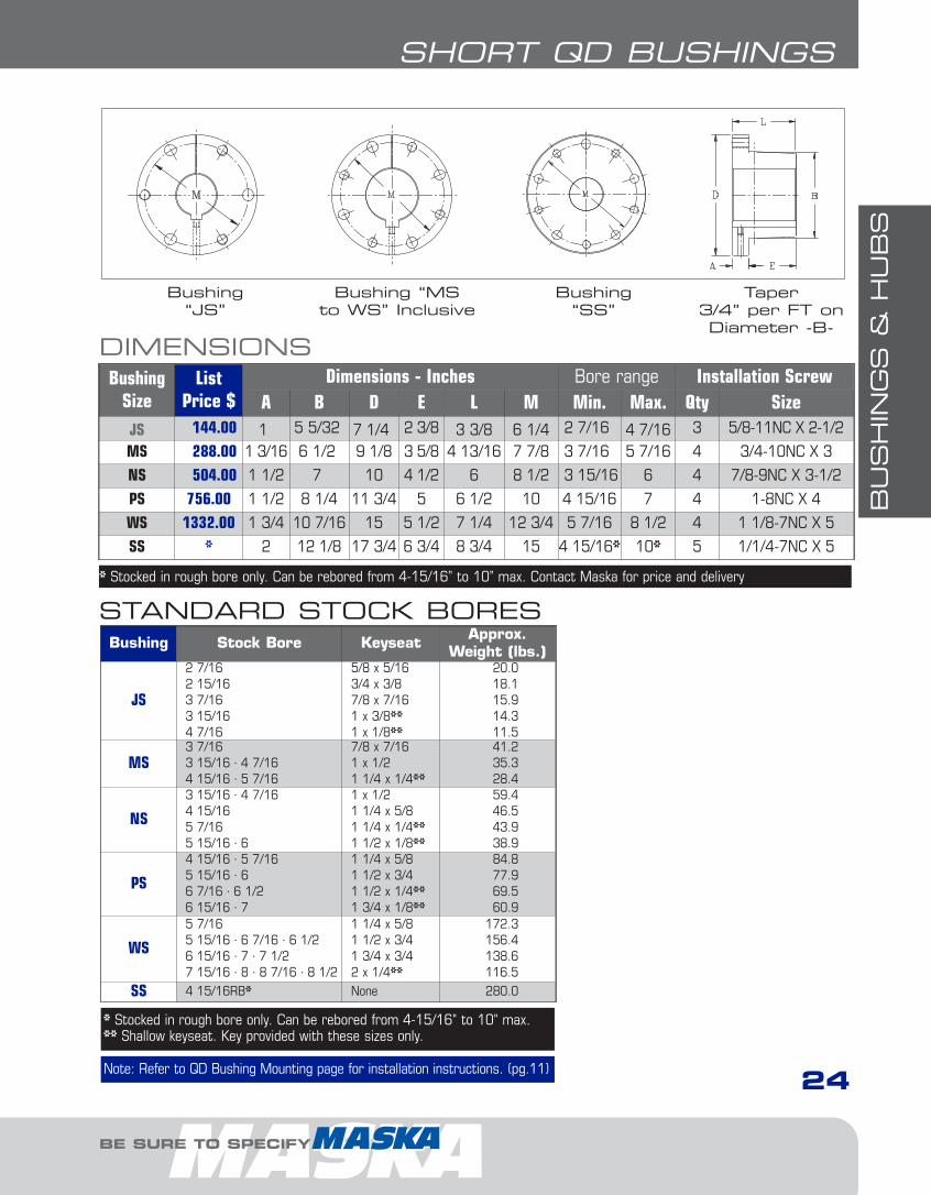
“SHORT” QD BUSHINGSUsage: For applications when the full bore length isnot needed, such as in conveyor applications or witha roller chain sprocket.
• All sizes with a shallow keyseat are in DUCTILEiron for greater strength
• Same features as the standard QD bushingwith the exception that the total length isreduced to adapt to a QD weld-on hub
• Full, not partial split• Sizes J, M, N, P, W (S is available in rough bore
only)
DID YOU KNOW THAT...
EXAMPLE: MSX4-7/16
MS X4-7/16
MS: BUSHING SIZE
X4-7/16: BORE SIZE (4-7/16")Inch bore sizes are designated with thewhole inch followed by the fraction. For example, a 1.5” diameter bore would be1-1/2.
HOW TO ORDER
1-Bushings1.10.qxp 2009-03-19 13:56 Page 16
BU
SH
ING
S &
HU
BS
24
BE SURE TO SPECIFY
SHORT QD BUSHINGS
Bushing Stock Bore Keyseat Approx.Weight (lbs.)
JS
2 7/162 15/163 7/163 15/164 7/16
5/8 x 5/163/4 x 3/87/8 x 7/161 x 3/8**1 x 1/8**
20.018.115.914.311.5
MS3 7/163 15/16 · 4 7/164 15/16 · 5 7/16
7/8 x 7/161 x 1/21 1/4 x 1/4**
41.235.328.4
NS
3 15/16 · 4 7/164 15/165 7/165 15/16 · 6
1 x 1/21 1/4 x 5/81 1/4 x 1/4**1 1/2 x 1/8**
59.446.543.938.9
PS
4 15/16 · 5 7/165 15/16 · 66 7/16 · 6 1/26 15/16 · 7
1 1/4 x 5/81 1/2 x 3/41 1/2 x 1/4**1 3/4 x 1/8**
84.877.969.560.9
WS
5 7/165 15/16 · 6 7/16 · 6 1/26 15/16 · 7 · 7 1/27 15/16 · 8 · 8 7/16 · 8 1/2
1 1/4 x 5/81 1/2 x 3/41 3/4 x 3/42 x 1/4**
172.3156.4138.6116.5
SS 4 15/16RB* None 280.0
STANDARD STOCK BORES
* Stocked in rough bore only. Can be rebored from 4-15/16" to 10" max.** Shallow keyseat. Key provided with these sizes only.
Bushing“JS”
Bushing “MS to WS” Inclusive
Bushing“SS”
Taper 3/4” per FT on Diameter -B-
DIMENSIONSBushing
SizeList
Price $Dimensions - Inches Bore range Installation Screw
A B D E L M Min. Max. Qty SizeJS 144.00 1 5 5/32 7 1/4 2 3/8 3 3/8 6 1/4 2 7/16 4 7/16 3 5/8-11NC X 2-1/2
MS 288.00 1 3/16 6 1/2 9 1/8 3 5/8 4 13/16 7 7/8 3 7/16 5 7/16 4 3/4-10NC X 3
NS 504.00 1 1/2 7 10 4 1/2 6 8 1/2 3 15/16 6 4 7/8-9NC X 3-1/2
PS 756.00 1 1/2 8 1/4 11 3/4 5 6 1/2 10 4 15/16 7 4 1-8NC X 4
WS 1332.00 1 3/4 10 7/16 15 5 1/2 7 1/4 12 3/4 5 7/16 8 1/2 4 1 1/8-7NC X 5
SS * 2 12 1/8 17 3/4 6 3/4 8 3/4 15 4 15/16* 10* 5 1/1/4-7NC X 5
* Stocked in rough bore only. Can be rebored from 4-15/16” to 10” max. Contact Maska for price and delivery
Note: Refer to QD Bushing Mounting page for installation instructions. (pg.11)
1-Bushings1.10.qxp 2009-03-19 13:56 Page 17
BU
SH
ING
S &
HU
BS
25
QD WELD-ON HUBS
FOR DEPENDABLE DRIVE COMPONENTS, BE SURE TO SPECIFY
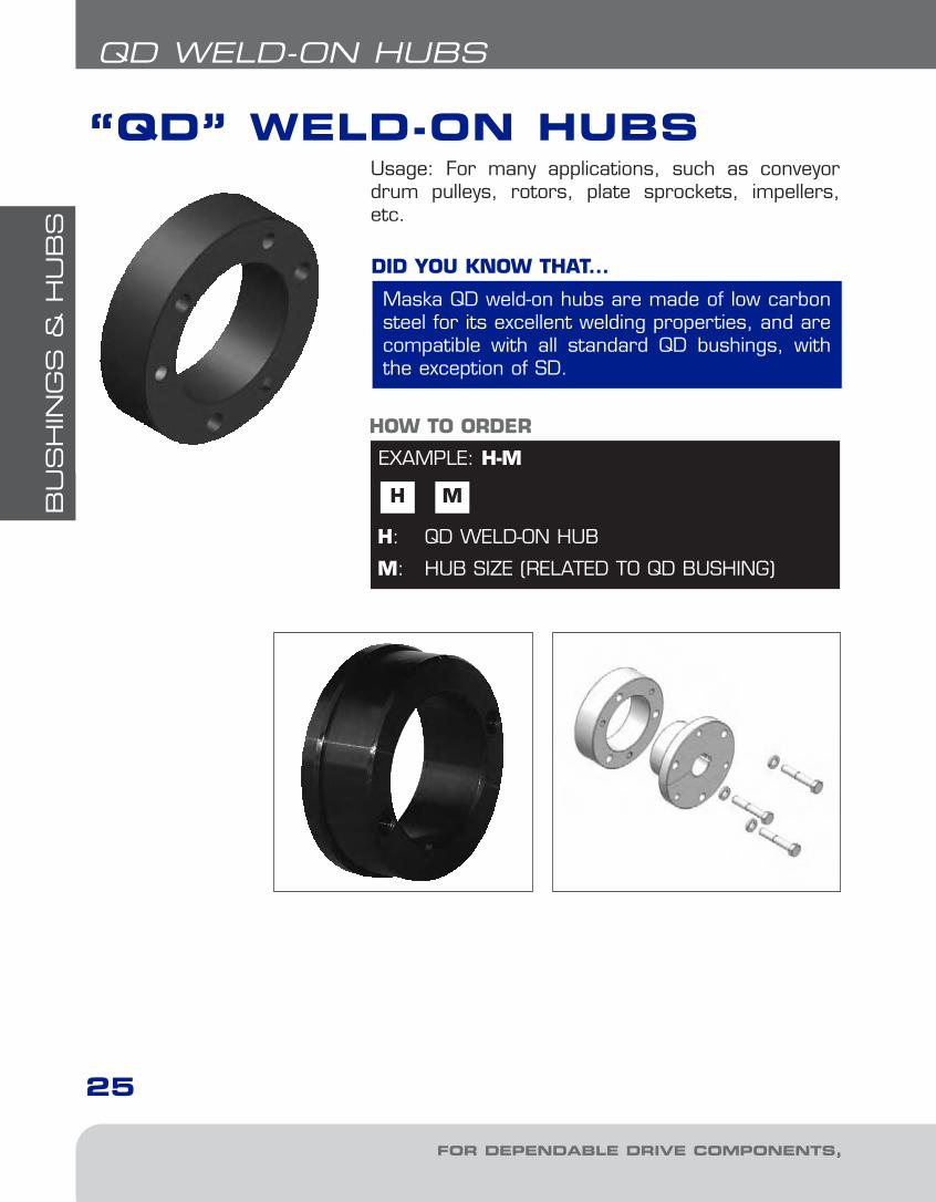
“QD” WELD-ON HUBSUsage: For many applications, such as conveyordrum pulleys, rotors, plate sprockets, impellers,etc.
Maska QD weld-on hubs are made of low carbonsteel for its excellent welding properties, and arecompatible with all standard QD bushings, withthe exception of SD.
DID YOU KNOW THAT...
EXAMPLE: H-M
H M
H: QD WELD-ON HUB
M: HUB SIZE (RELATED TO QD BUSHING)
HOW TO ORDER
1-Bushings1.10.qxp 2009-03-19 13:56 Page 18

BU
SH
ING
S &
HU
BS
26
BE SURE TO SPECIFY
QD WELD-ON HUBS
DIMENSIONSPartNo.
ListPrice $
FitsBushing
TypeDimensions - Inches Bore
RangeApprox.WeightD* L P L1 BC
H-L 9.00 L 1 2.375 0.88 2.50 0.17 2 3/8 to 1 1/2” 0.6
H-CL 9.00 L 1 2.375 0.88 2.50 0.63 2 3/8 to 1 1/2” 0.6
H-JA 9.00 JA 2 2.250 0.56 ... ... 1 21/32 1/2 to 1 1/4” 0.4
H-SH 15.00 SH 2 3.000 0.81 ... ... 2 1/4 1/2 to 1 11/16” 1
H-SDS 14.00 SDS 2 3.500 0.75 ... ... 2 11/16 1/2 to 2” 1.2
H-SK 27.00 SK 2 4.375 1.25 ... ... 3 5/16 1/2 to 2 5/8” 3
H-SF 35.00 SF 2 5.000 1.25 ... ... 3 7/8 1/2 to 2 15/16” 4
H-E 72.00 E 2 6.250 1.63 ... ... 5 7/8 to 3 1/2” 8.3
H-F 120.00 F 2 7.000 2.50 ... ... 5 5/8 1 to 4” 15.5
H-J 175.00 J 2 7.750 3.19 ... ... 6 1/4 1 7/16 to 4 1/2” 22.7
H-M 310.00 M 3 9.250 5.19 9.50 3.56 7 7/8 2 to 5 1/2” 50
H-N 460.00 N 3 10.250 6.25 10.50 4.50 8 1/2 2 3/4 to 6” 77
H-P ¬ 1460.00 P 2 13.000 7.25 ... ... 10 2 15/16 to 7” 155
H-W ¬ 2300.00 W 2 15.500 9.00 ... ... 12 3/4 4 1/4 to 8 1/2” 260
Mounting: Type 1: Reverse mount only Type 2 & 3: Standard and Reverse mount ¬: Standard mount only *Tolerance: H-L & H-CL = (+0.001”/-0.005”) H-JA thru H-J = (+0.000”/-0.002”) H-M thru H-W = (+0.000”/-0.003”)
45o
45o45o
30o
90o
75o
Type 3Type 2Type 1
1-Bushings1.10.qxp 2009-03-19 13:56 Page 19

BU
SH
ING
S &
HU
BS
27
XT BUSHINGS
FOR DEPENDABLE DRIVE COMPONENTS, BE SURE TO SPECIFY
XT BUSHINGS
• 2”/ft. taper for easy on, easy off• In steel & gray cast iron
DID YOU KNOW THAT...
EXAMPLE: XTB20X2
XTB 20
XTB: XT BUSHING
20: BUSHING SIZEMeans that the maximum bore for this bushing is 2.0”
X2: BORE SIZE (2”)Inch bore sizes are designated with thewhole inch following by fraction. For example,a 1.5” diameter bore would be 1-1/2.
HOW TO ORDER
For the first month of operation,inspect bushings and capscrews forproper seating at least once a weekand thereafter during periodic shutdown.
IMPORTANT REMINDER
XTB15 TO XTB80INCLUSIVE
XTB100 XTB120 SECTION A-ATaper 2” per ft.on diameter -B-
Usage: Bushing sizes 15-45 are made of steel. Thisproduct is specially designed for conveyor pulleyapplications.
X2
1-Bushings1.10.qxp 2009-03-19 13:56 Page 20
BU
SH
ING
S &
HU
BS
28
BE SURE TO SPECIFY
XT BUSHINGS
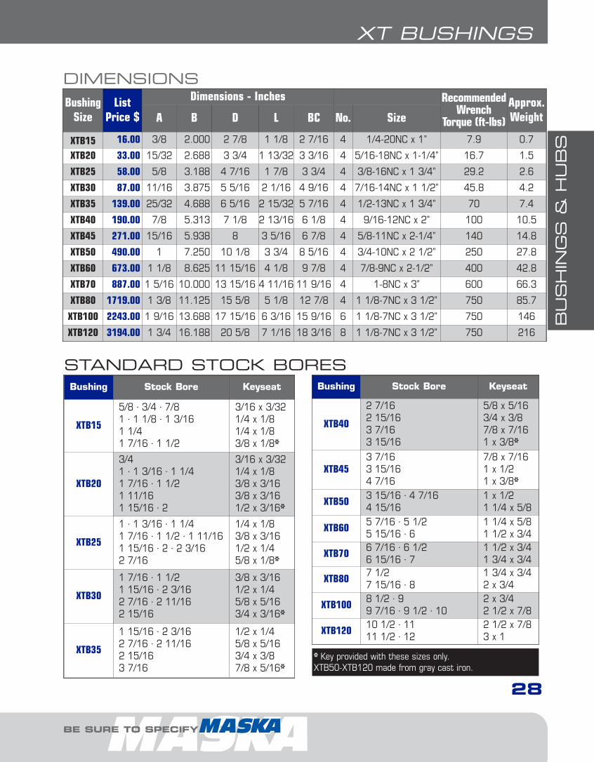
DIMENSIONSBushing
SizeList
Price $
Dimensions - Inches RecommendedWrench
Torque (ft-lbs)
Approx.WeightA B D L BC No. Size
XTB15 16.00 3/8 2.000 2 7/8 1 1/8 2 7/16 4 1/4-20NC x 1” 7.9 0.7
XTB20 33.00 15/32 2.688 3 3/4 1 13/32 3 3/16 4 5/16-18NC x 1-1/4” 16.7 1.5
XTB25 58.00 5/8 3.188 4 7/16 1 7/8 3 3/4 4 3/8-16NC x 1 3/4” 29.2 2.6
XTB30 87.00 11/16 3.875 5 5/16 2 1/16 4 9/16 4 7/16-14NC x 1 1/2” 45.8 4.2
XTB35 139.00 25/32 4.688 6 5/16 2 15/32 5 7/16 4 1/2-13NC x 1 3/4” 70 7.4
XTB40 190.00 7/8 5.313 7 1/8 2 13/16 6 1/8 4 9/16-12NC x 2” 100 10.5
XTB45 271.00 15/16 5.938 8 3 5/16 6 7/8 4 5/8-11NC x 2-1/4” 140 14.8
XTB50 490.00 1 7.250 10 1/8 3 3/4 8 5/16 4 3/4-10NC x 2 1/2” 250 27.8
XTB60 673.00 1 1/8 8.625 11 15/16 4 1/8 9 7/8 4 7/8-9NC x 2-1/2” 400 42.8
XTB70 887.00 1 5/16 10.000 13 15/16 4 11/16 11 9/16 4 1-8NC x 3” 600 66.3
XTB80 1719.00 1 3/8 11.125 15 5/8 5 1/8 12 7/8 4 1 1/8-7NC x 3 1/2” 750 85.7
XTB100 2243.00 1 9/16 13.688 17 15/16 6 3/16 15 9/16 6 1 1/8-7NC x 3 1/2” 750 146
XTB120 3194.00 1 3/4 16.188 20 5/8 7 1/16 18 3/16 8 1 1/8-7NC x 3 1/2” 750 216
STANDARD STOCK BORES
* Key provided with these sizes only.XTB50-XTB120 made from gray cast iron.
Bushing Stock Bore Keyseat
XTB15
5/8 · 3/4 · 7/81 · 1 1/8 · 1 3/161 1/41 7/16 · 1 1/2
3/16 x 3/321/4 x 1/81/4 x 1/83/8 x 1/8*
XTB20
3/41 · 1 3/16 · 1 1/41 7/16 · 1 1/21 11/161 15/16 · 2
3/16 x 3/321/4 x 1/83/8 x 3/163/8 x 3/161/2 x 3/16*
XTB25
1 · 1 3/16 · 1 1/41 7/16 · 1 1/2 · 1 11/161 15/16 · 2 · 2 3/162 7/16
1/4 x 1/83/8 x 3/161/2 x 1/45/8 x 1/8*
XTB30
1 7/16 · 1 1/21 15/16 · 2 3/162 7/16 · 2 11/162 15/16
3/8 x 3/161/2 x 1/45/8 x 5/163/4 x 3/16*
XTB35
1 15/16 · 2 3/162 7/16 · 2 11/162 15/163 7/16
1/2 x 1/45/8 x 5/163/4 x 3/87/8 x 5/16*
Bushing Stock Bore Keyseat
XTB40
2 7/162 15/163 7/163 15/16
5/8 x 5/163/4 x 3/87/8 x 7/161 x 3/8*
XTB453 7/163 15/164 7/16
7/8 x 7/161 x 1/21 x 3/8*
XTB50 3 15/16 · 4 7/164 15/16
1 x 1/21 1/4 x 5/8
XTB60 5 7/16 · 5 1/25 15/16 · 6
1 1/4 x 5/81 1/2 x 3/4
XTB70 6 7/16 · 6 1/26 15/16 · 7
1 1/2 x 3/41 3/4 x 3/4
XTB80 7 1/2 7 15/16 · 8
1 3/4 x 3/42 x 3/4
XTB100 8 1/2 · 99 7/16 · 9 1/2 · 10
2 x 3/42 1/2 x 7/8
XTB120 10 1/2 · 1111 1/2 · 12
2 1/2 x 7/83 x 1
1-Bushings1.10.qxp 2009-03-19 13:56 Page 21
BU
SH
ING
S &
HU
BS
29
XT HUBS
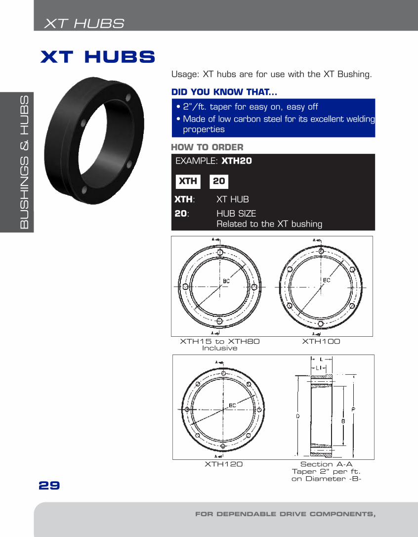
EXAMPLE: XTH20
XTH
HOW TO ORDER
XT HUBS
FOR DEPENDABLE DRIVE COMPONENTS, BE SURE TO SPECIFY
XTH120 Section A-ATaper 2” per ft.on Diameter -B-
XTH15 to XTH80Inclusive
XTH100
Usage: XT hubs are for use with the XT Bushing.
• 2”/ft. taper for easy on, easy off• Made of low carbon steel for its excellent welding
properties
DID YOU KNOW THAT...
20
XTH: XT HUB
20: HUB SIZERelated to the XT bushing
1-Bushings1.10.qxp 2009-03-19 13:56 Page 22
BU
SH
ING
S &
HU
BS
30
BE SURE TO SPECIFY
XT HUBS
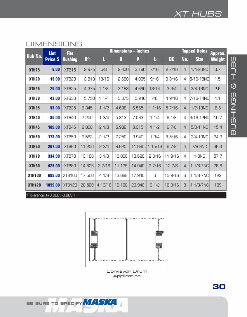
DIMENSIONS
Hub No.List
Price $Fits
Bushing
Dimensions - Inches Tapped Holes Approx.WeightD* L B P L BC No. Size
XTH15 8.00 XTB15 2.875 5/8 2.000 3.190 7/16 2 7/16 4 1/4-20NC 0.7
XTH20 15.00 XTB20 3.813 13/16 2.688 4.065 9/16 3 3/16 4 5/16-18NC 1.5
XTH25 25.00 XTB25 4.375 1 1/8 3.188 4.690 13/16 3 3/4 4 3/8-16NC 2.6
XTH30 43.00 XTB30 5.750 1 1/4 3.875 5.940 7/8 4 9/16 4 7/16-14NC 4.1
XTH35 55.00 XTB35 6.345 1 1/2 4.688 6.565 1 1/16 5 7/16 4 1/2-13NC 6.6
XTH40 85.00 XTB40 7.250 1 3/4 5.313 7.563 1 1/4 6 1/8 4 9/16-12NC 10.7
XTH45 109.00 XTB45 8.000 2 1/8 5.938 8.315 1 1/2 6 7/8 4 5/8-11NC 15.4
XTH50 173.00 XTB50 9.563 2 1/2 7.250 9.940 1 3/4 8 5/16 4 3/4-10NC 24.9
XTH60 267.00 XTB60 11.250 2 3/4 8.625 11.690 1 15/16 9 7/8 4 7/8-9NC 36.4
XTH70 334.00 XTB70 13.188 3 1/8 10.000 13.628 2 3/16 11 9/16 4 1-8NC 57.7
XTH80 425.00 XTB80 14.625 3 7/16 11.125 14.940 2 7/16 12 7/8 4 1 1/8-7NC 75.6
XTH100 699.00 XTB100 17.500 4 1/8 13.688 17.940 3 15 9/16 6 1 1/8-7NC 122
XTH120 1059.00 XTB120 20.500 4 13/16 16.188 20.940 3 1/2 18 3/16 8 1 1/8-7NC 189
* Tolerance: (+0.000”/-0.005”)
Conveyor DrumApplication
1
1-Bushings1.10.qxp 2009-03-19 13:56 Page 23
SH
EAVES
31
GENERAL SHEAVES INFORMATION
FOR DEPENDABLE DRIVE COMPONENTS, BE SURE TO SPECIFY
• Light Duty• Adjustable Pitch• Classical V-belt• Narrow V-belt
• Elasticity of belts helps shock load dampening• Good mechanical efficiency• Long-life expectancy when well designed• Quiet, smooth operation; no lubrification required• Easy and economical installation• Clean and low maintenance
DID YOU KNOW THAT...
GENERAL INFORMATIONV-BELT DRIVE SHEAVES
DO NOT use these gray cast iron sheaves with rim speeds inexcess of 6500 feet per minute. Note that the maximum RPMindicated on the sheave is based on the 6500 ft/min. limit and
doesn't take into consideration the need for dynamic balancing (twoplanes). Please refer to the chart on page 32 to verify the validity ofdynamic balancing in your application.All operational PT products when used in a drive are potentially danger-ous and must be guarded by the user as required by applicable laws, regulations, standards and good safety practice. (Refer to ANSIStandard B15.1)
IMPORTANT REMINDER
DYNAMIC BALANCINGWhen ordering a sheave to be dynamically balanced, you must specify the sheaveoperational speed. Maska recommends ordering the matching bushing with thesheave to ensure a balancing grade of G6.3. If the bushing is not ordered at thesame time, a disclaimer will be sent to the customer discharging Maska from possible vibration problems related to the drive.
2-FHP Sheaves1.13.qxp 2009-03-19 14:05 Page 2

SH
EAVES
32
GENERAL SHEAVES INFORMATION
BE SURE TO SPECIFY
BALANCING STANDARDS
Conventional Belt Sheaves, # of grooves
2
2
2
2
21 3 4 5 6 7 8 9 10 15 20 25 30
5 10 15 20
2015105
5 10 15 20
5 10 15 20D
C
B
A
BELTSECT.
4
5
6
7
8
9
10
15
20
25
30
40
50
60
3V
5V
8V
2
2
2
5
5
5
10
10
10
15
15
15
19
19
19
400
500
600
700
800
900
100011001200130014001500
1750
200022002400260028003000
3500
4000
45005000
6000
7000
8000
RPM (R
EVOL
UTION
S PER
MIN
UTE)
NORMAL FACE WIDTH IN INCHES
DIAM
ETER
S IN
INCH
ES
NOMOGRAPHThis nomograph shows the maximum speed limit (in RPM) for a gray cast iron standardstatically balanced pulley of a given diameter and face width. To exceed this speed limit,the pulley should also be dynamically balanced.
Example: If you have a 6-8V14.0 pulley (see 8V section) with a diameter of 14” and a facewidth of 7 1/8”, and it must turn at 1,800 RPM, what type of balancing is required?
Answer: As shown, the limit for this pulley would be 1,500 RPM, therefore it must bedynamically balanced.
NARROW V-BELT SHEAVES, # OF GROOVES
CONVENTIONAL BELT SHEAVES, # OF GROOVES
2-FHP Sheaves1.13.qxp 2009-03-19 14:05 Page 3
SH
EAVES
33
GENERAL SHEAVES INFORMATION
FOR DEPENDABLE DRIVE COMPONENTS, BE SURE TO SPECIFY
COMPLEMENTARY INFORMATION
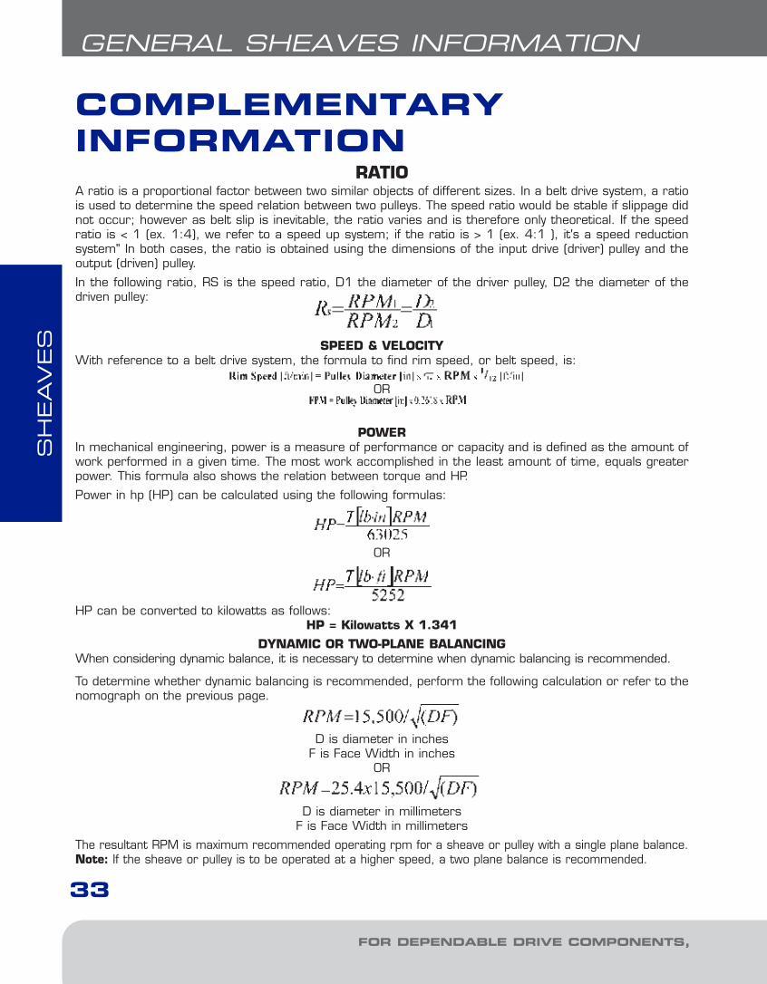
RATIOA ratio is a proportional factor between two similar objects of different sizes. In a belt drive system, a ratiois used to determine the speed relation between two pulleys. The speed ratio would be stable if slippage didnot occur; however as belt slip is inevitable, the ratio varies and is therefore only theoretical. If the speedratio is < 1 (ex. 1:4), we refer to a speed up system; if the ratio is > 1 (ex. 4:1 ), it's a speed reductionsystem" In both cases, the ratio is obtained using the dimensions of the input drive (driver) pulley and theoutput (driven) pulley.
In the following ratio, RS is the speed ratio, D1 the diameter of the driver pulley, D2 the diameter of thedriven pulley:
SPEED & VELOCITYWith reference to a belt drive system, the formula to find rim speed, or belt speed, is:
OR
POWERIn mechanical engineering, power is a measure of performance or capacity and is defined as the amount ofwork performed in a given time. The most work accomplished in the least amount of time, equals greaterpower. This formula also shows the relation between torque and HP.
Power in hp (HP) can be calculated using the following formulas:
OR
HP can be converted to kilowatts as follows:HP = Kilowatts X 1.341
DYNAMIC OR TWO-PLANE BALANCINGWhen considering dynamic balance, it is necessary to determine when dynamic balancing is recommended.
To determine whether dynamic balancing is recommended, perform the following calculation or refer to thenomograph on the previous page.
D is diameter in inchesF is Face Width in inches
OR
D is diameter in millimetersF is Face Width in millimeters
The resultant RPM is maximum recommended operating rpm for a sheave or pulley with a single plane balance.Note: If the sheave or pulley is to be operated at a higher speed, a two plane balance is recommended.
2-FHP Sheaves1.13.qxp 2009-03-19 14:05 Page 4
SH
EAVES
34
BE SURE TO SPECIFY
NOTES
GENERAL SHEAVES INFORMATION
2-FHP Sheaves1.13.qxp 2009-03-19 14:05 Page 5
SH
EAVES
35
GENERAL SHEAVES
FOR DEPENDABLE DRIVE COMPONENTS, BE SURE TO SPECIFY
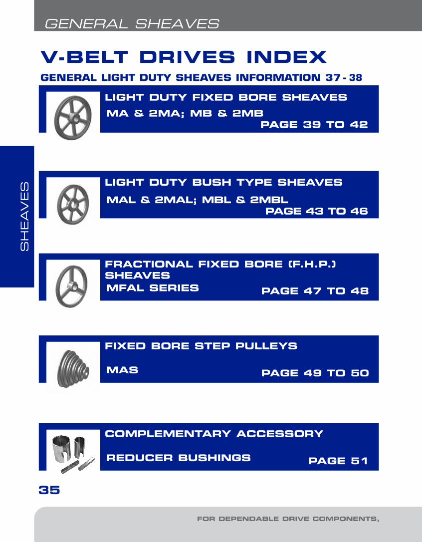
V-BELT DRIVES INDEX
LIGHT DUTY FIXED BORE SHEAVES
MA & 2MA; MB & 2MB PAGE 39 TO 42
MAL & 2MAL; MBL & 2MBL PAGE 43 TO 46
MFAL SERIES PAGE 47 TO 48
MAS PAGE 49 TO 50
REDUCER BUSHINGS PAGE 51
LIGHT DUTY BUSH TYPE SHEAVES
FRACTIONAL FIXED BORE (F.H.P.)SHEAVES
FIXED BORE STEP PULLEYS
COMPLEMENTARY ACCESSORY
GENERAL LIGHT DUTY SHEAVES INFORMATION 37 - 38
2-FHP Sheaves1.13.qxp 2009-03-19 14:05 Page 6
SH
EAVES
36
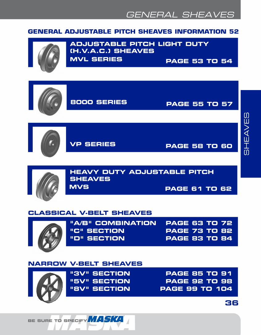
GENERAL SHEAVES
BE SURE TO SPECIFY
MVL SERIES PAGE 53 TO 54
8000 SERIES PAGE 55 TO 57
VP SERIES PAGE 58 TO 60
MVS PAGE 61 TO 62
CLASSICAL V-BELT SHEAVES
"D" SECTION PAGE 83 TO 84
NARROW V-BELT SHEAVES
"A/B" COMBINATION PAGE 63 TO 72"C" SECTION PAGE 73 TO 82
"8V" SECTION PAGE 99 TO 104
"3V" SECTION PAGE 85 TO 91"5V" SECTION PAGE 92 TO 98
ADJUSTABLE PITCH LIGHT DUTY(H.V.A.C.) SHEAVES
HEAVY DUTY ADJUSTABLE PITCHSHEAVES
GENERAL ADJUSTABLE PITCH SHEAVES INFORMATION 52
2-FHP Sheaves1.13.qxp 2009-03-19 14:05 Page 7
LIGHT DUTY SHEAVES
SH
EAVES
37
LIGHT DUTY SHEAVES
FOR DEPENDABLE DRIVE COMPONENTS, BE SURE TO SPECIFY
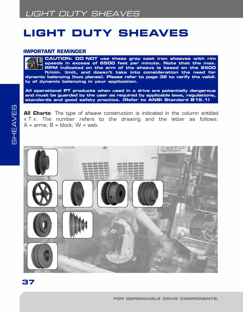
All Charts: The type of sheave construction is indicated in the column entitled« T ». The number refers to the drawing and the letter as follows: A = arms; B = block; W = web.
CAUTION: DO NOT use these gray cast iron sheaves with rimspeeds in excess of 6500 feet per minute. Note that the max.RPM indicated on the arm of the sheave is based on the 6500ft/min. limit, and doesn’t take into consideration the need for
dynamic balancing (two planes). Please refer to page 32 to verify the validi-ty of dynamic balancing in your application.
All operational PT products when used in a drive are potentially dangerousand must be guarded by the user as required by applicable laws, regulations,standards and good safety practice. (Refer to ANSI Standard B15.1)
IMPORTANT REMINDER
LIGHT DUTY SHEAVES
2-FHP Sheaves1.13.qxp 2009-03-19 14:05 Page 8
SH
EAVES
38
LIGHT DUTY FIXED BORE & BUSH TYPE
BE SURE TO SPECIFY
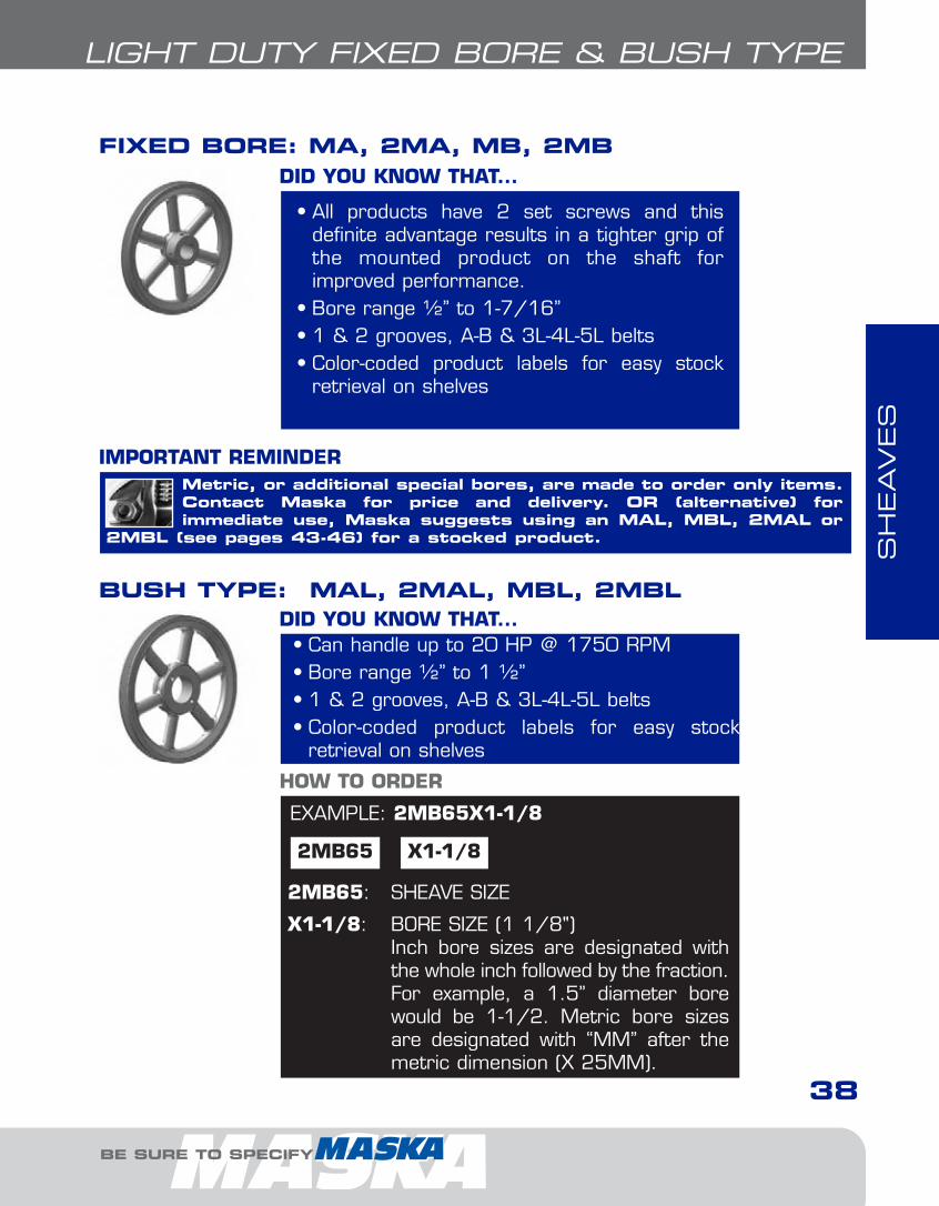
EXAMPLE: 2MB65X1-1/8
2MB65 X1-1/8
2MB65: SHEAVE SIZE
X1-1/8: BORE SIZE (1 1/8")Inch bore sizes are designated withthe whole inch followed by the fraction.For example, a 1.5” diameter borewould be 1-1/2. Metric bore sizesare designated with “MM” after themetric dimension (X 25MM).
HOW TO ORDER
• All products have 2 set screws and this definite advantage results in a tighter grip ofthe mounted product on the shaft forimproved performance.
• Bore range ½” to 1-7/16”• 1 & 2 grooves, A-B & 3L-4L-5L belts• Color-coded product labels for easy stock
retrieval on shelves
DID YOU KNOW THAT...
FIXED BORE: MA, 2MA, MB, 2MB
• Can handle up to 20 HP @ 1750 RPM• Bore range ½” to 1 ½”• 1 & 2 grooves, A-B & 3L-4L-5L belts• Color-coded product labels for easy stock
retrieval on shelves
DID YOU KNOW THAT...
Metric, or additional special bores, are made to order only items.Contact Maska for price and delivery. OR (alternative) for immediate use, Maska suggests using an MAL, MBL, 2MAL or
2MBL (see pages 43-46) for a stocked product.
IMPORTANT REMINDER
BUSH TYPE: MAL, 2MAL, MBL, 2MBL
2-FHP Sheaves1.13.qxp 2009-03-19 14:05 Page 9
SH
EAVES
SH
EAVES
MA (A & 3L-4L V-BELTS)
39
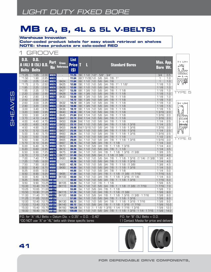
LIGHT DUTY FIXED BORE
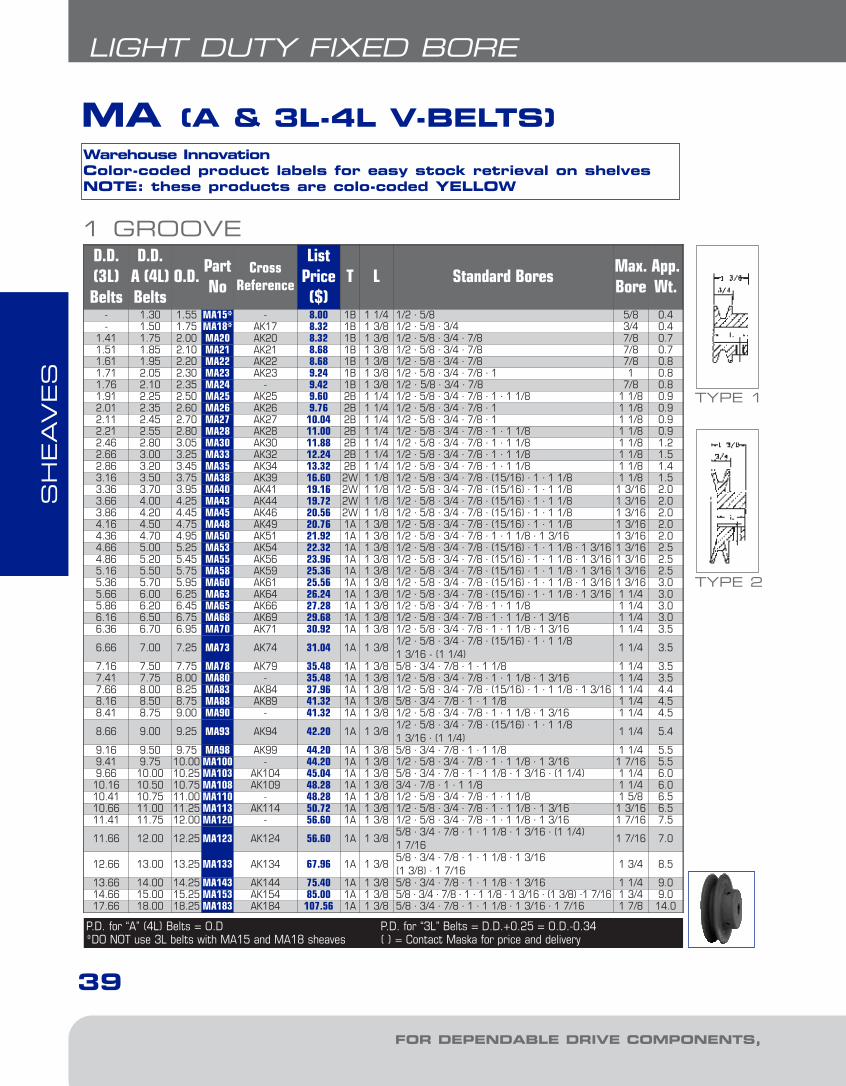
1 GROOVED.D. (3L)Belts
D.D. A (4L)Belts
O.D.PartNo
CrossReference
ListPrice($)
T L Standard BoresMax.Bore
App.Wt.
- 1.30 1.55 MA15* - 8.00 1B 1 1/4 1/2 · 5/8 5/8 0.4- 1.50 1.75 MA18* AK17 8.32 1B 1 3/8 1/2 · 5/8 · 3/4 3/4 0.4
1.41 1.75 2.00 MA20 AK20 8.32 1B 1 3/8 1/2 · 5/8 · 3/4 · 7/8 7/8 0.71.51 1.85 2.10 MA21 AK21 8.68 1B 1 3/8 1/2 · 5/8 · 3/4 · 7/8 7/8 0.71.61 1.95 2.20 MA22 AK22 8.68 1B 1 3/8 1/2 · 5/8 · 3/4 · 7/8 7/8 0.81.71 2.05 2.30 MA23 AK23 9.24 1B 1 3/8 1/2 · 5/8 · 3/4 · 7/8 · 1 1 0.81.76 2.10 2.35 MA24 - 9.42 1B 1 3/8 1/2 · 5/8 · 3/4 · 7/8 7/8 0.81.91 2.25 2.50 MA25 AK25 9.60 2B 1 1/4 1/2 · 5/8 · 3/4 · 7/8 · 1 · 1 1/8 1 1/8 0.92.01 2.35 2.60 MA26 AK26 9.76 2B 1 1/4 1/2 · 5/8 · 3/4 · 7/8 · 1 1 1/8 0.92.11 2.45 2.70 MA27 AK27 10.04 2B 1 1/4 1/2 · 5/8 · 3/4 · 7/8 · 1 1 1/8 0.92.21 2.55 2.80 MA28 AK28 11.00 2B 1 1/4 1/2 · 5/8 · 3/4 · 7/8 · 1 · 1 1/8 1 1/8 0.92.46 2.80 3.05 MA30 AK30 11.88 2B 1 1/4 1/2 · 5/8 · 3/4 · 7/8 · 1 · 1 1/8 1 1/8 1.22.66 3.00 3.25 MA33 AK32 12.24 2B 1 1/4 1/2 · 5/8 · 3/4 · 7/8 · 1 · 1 1/8 1 1/8 1.52.86 3.20 3.45 MA35 AK34 13.32 2B 1 1/4 1/2 · 5/8 · 3/4 · 7/8 · 1 · 1 1/8 1 1/8 1.43.16 3.50 3.75 MA38 AK39 16.60 2W 1 1/8 1/2 · 5/8 · 3/4 · 7/8 · (15/16) · 1 · 1 1/8 1 1/8 1.53.36 3.70 3.95 MA40 AK41 19.16 2W 1 1/8 1/2 · 5/8 · 3/4 · 7/8 · (15/16) · 1 · 1 1/8 1 3/16 2.03.66 4.00 4.25 MA43 AK44 19.72 2W 1 1/8 1/2 · 5/8 · 3/4 · 7/8 · (15/16) · 1 · 1 1/8 1 3/16 2.03.86 4.20 4.45 MA45 AK46 20.56 2W 1 1/8 1/2 · 5/8 · 3/4 · 7/8 · (15/16) · 1 · 1 1/8 1 3/16 2.04.16 4.50 4.75 MA48 AK49 20.76 1A 1 3/8 1/2 · 5/8 · 3/4 · 7/8 · (15/16) · 1 · 1 1/8 1 3/16 2.04.36 4.70 4.95 MA50 AK51 21.92 1A 1 3/8 1/2 · 5/8 · 3/4 · 7/8 · 1 · 1 1/8 · 1 3/16 1 3/16 2.04.66 5.00 5.25 MA53 AK54 22.32 1A 1 3/8 1/2 · 5/8 · 3/4 · 7/8 · (15/16) · 1 · 1 1/8 · 1 3/16 1 3/16 2.54.86 5.20 5.45 MA55 AK56 23.96 1A 1 3/8 1/2 · 5/8 · 3/4 · 7/8 · (15/16) · 1 · 1 1/8 · 1 3/16 1 3/16 2.55.16 5.50 5.75 MA58 AK59 25.36 1A 1 3/8 1/2 · 5/8 · 3/4 · 7/8 · (15/16) · 1 · 1 1/8 · 1 3/16 1 3/16 2.55.36 5.70 5.95 MA60 AK61 25.56 1A 1 3/8 1/2 · 5/8 · 3/4 · 7/8 · (15/16) · 1 · 1 1/8 · 1 3/16 1 3/16 3.05.66 6.00 6.25 MA63 AK64 26.24 1A 1 3/8 1/2 · 5/8 · 3/4 · 7/8 · (15/16) · 1 · 1 1/8 · 1 3/16 1 1/4 3.05.86 6.20 6.45 MA65 AK66 27.28 1A 1 3/8 1/2 · 5/8 · 3/4 · 7/8 · 1 · 1 1/8 1 1/4 3.06.16 6.50 6.75 MA68 AK69 29.68 1A 1 3/8 1/2 · 5/8 · 3/4 · 7/8 · 1 · 1 1/8 · 1 3/16 1 1/4 3.06.36 6.70 6.95 MA70 AK71 30.92 1A 1 3/8 1/2 · 5/8 · 3/4 · 7/8 · 1 · 1 1/8 · 1 3/16 1 1/4 3.5
6.66 7.00 7.25 MA73 AK74 31.04 1A 1 3/81/2 · 5/8 · 3/4 · 7/8 · (15/16) · 1 · 1 1/81 3/16 - (1 1/4)
1 1/4 3.5
7.16 7.50 7.75 MA78 AK79 35.48 1A 1 3/8 5/8 · 3/4 · 7/8 · 1 · 1 1/8 1 1/4 3.57.41 7.75 8.00 MA80 - 35.48 1A 1 3/8 1/2 · 5/8 · 3/4 · 7/8 · 1 · 1 1/8 · 1 3/16 1 1/4 3.57.66 8.00 8.25 MA83 AK84 37.96 1A 1 3/8 1/2 · 5/8 · 3/4 · 7/8 · (15/16) · 1 · 1 1/8 · 1 3/16 1 1/4 4.48.16 8.50 8.75 MA88 AK89 41.32 1A 1 3/8 5/8 · 3/4 · 7/8 · 1 · 1 1/8 1 1/4 4.58.41 8.75 9.00 MA90 - 41.32 1A 1 3/8 1/2 · 5/8 · 3/4 · 7/8 · 1 · 1 1/8 · 1 3/16 1 1/4 4.5
8.66 9.00 9.25 MA93 AK94 42.20 1A 1 3/81/2 · 5/8 · 3/4 · 7/8 · (15/16) · 1 · 1 1/81 3/16 · (1 1/4)
1 1/4 5.4
9.16 9.50 9.75 MA98 AK99 44.20 1A 1 3/8 5/8 · 3/4 · 7/8 · 1 · 1 1/8 1 1/4 5.59.41 9.75 10.00 MA100 - 44.20 1A 1 3/8 1/2 · 5/8 · 3/4 · 7/8 · 1 · 1 1/8 · 1 3/16 1 7/16 5.59.66 10.00 10.25 MA103 AK104 45.04 1A 1 3/8 5/8 · 3/4 · 7/8 · 1 · 1 1/8 · 1 3/16 · (1 1/4) 1 1/4 6.010.16 10.50 10.75 MA108 AK109 48.28 1A 1 3/8 3/4 · 7/8 · 1 · 1 1/8 1 1/4 6.010.41 10.75 11.00 MA110 - 48.28 1A 1 3/8 1/2 · 5/8 · 3/4 · 7/8 · 1 · 1 1/8 1 5/8 6.510.66 11.00 11.25 MA113 AK114 50.72 1A 1 3/8 1/2 · 5/8 · 3/4 · 7/8 · 1 · 1 1/8 · 1 3/16 1 3/16 6.511.41 11.75 12.00 MA120 - 56.60 1A 1 3/8 1/2 · 5/8 · 3/4 · 7/8 · 1 · 1 1/8 · 1 3/16 1 7/16 7.5
11.66 12.00 12.25 MA123 AK124 56.60 1A 1 3/85/8 · 3/4 · 7/8 · 1 · 1 1/8 · 1 3/16 · (1 1/4)1 7/16
1 7/16 7.0
12.66 13.00 13.25 MA133 AK134 67.96 1A 1 3/85/8 · 3/4 · 7/8 · 1 · 1 1/8 · 1 3/16(1 3/8) · 1 7/16
1 3/4 8.5
13.66 14.00 14.25 MA143 AK144 75.40 1A 1 3/8 5/8 · 3/4 · 7/8 · 1 · 1 1/8 · 1 3/16 1 1/4 9.014.66 15.00 15.25 MA153 AK154 85.00 1A 1 3/8 5/8 · 3/4 · 7/8 · 1 · 1 1/8 · 1 3/16 · (1 3/8) ·1 7/16 1 3/4 9.017.66 18.00 18.25 MA183 AK184 107.56 1A 1 3/8 5/8 · 3/4 · 7/8 · 1 · 1 1/8 · 1 3/16 · 1 7/16 1 7/8 14.0
P.D. for “A” (4L) Belts = O.D P.D. for “3L” Belts = D.D.+0.25 = O.D.-0.34*DO NOT use 3L belts with MA15 and MA18 sheaves ( ) = Contact Maska for price and delivery
Warehouse InnovationColor-coded product labels for easy stock retrieval on shelvesNOTE: these products are colo-coded YELLOW
TYPE 1
TYPE 2
FOR DEPENDABLE DRIVE COMPONENTS, BE SURE TO SPECIFY
2-FHP Sheaves1.13.qxp 2009-03-19 14:05 Page 10

SH
EAVES
40
LIGHT DUTY FIXED BORE
Bore Range Keyseat
1/2”5/8” - 7/8”
15/16” - 1 1/4”1 5/16” - 1 3/8”1 7/16” - 1 3/4”
None3/16” X 3/32”1/4” X 1/8”
5/16” X 5/32”3/8” X 3/16”
2 GROOVESD.D. A
BeltsO.D.
PartNo
CrossReference
ListPrice($)
T L Standard BoresMax.Bore
App.Wt.
1.75 2.00 2MA20 2AK20 20.64 3B 2 1/16 l1/2 · 5/8 - 3/4 3/4 1.01.90 2.15 2MA22 2AK21 20.64 3B 2 1/16 1/2 - 5/8 - 3/4 - (7/8) 7/8 1.02.00 2.25 2MA23 2AK22 22.72 3B 2 1/16 1/2 - 5/8 - 3/4 - 7/8 - 1 1 1.02.10 2.35 2MA24 2AK23 22.72 4B 1 7/8 1/2 - 5/8 - 3/4 - 7/8 - (1) 1 1/8 1.02.30 2.55 2MA25 2AK25 22.88 4B 1 11/16 1/2 - 5/8 - 3/4 - 7/8 - 1 - 1 1/8 1 1/8 1.52.40 2.65 2MA27 2AK26 25.12 4B 1 7/8 1/2 - 5/8 - 3/4 - 7/8 - 1 - 1 1/8 1 1/8 1.52.50 2.75 2MA28 2AK27 27.68 4B 1 11/16 1/2 - 5/8 - 3/4 - 7/8 - 1 - 1 1/8 1 1/8 1.52.60 2.85 2MA29 2AK28 27.68 4B 1 11/16 1/2 - 5/8 - 3/4 - 7/8 - 1 - 1 1/8 1 1/8 1.52.80 3.05 2MA30 2AK30 30.72 4B 1 11/16 1/2 - 5/8 - 3/4 - 7/8 - 1 - 1 1/8 1 1/8 2.03.00 3.25 2MA33 2AK32 34.56 4B 1 5/8 1/2 - 5/8 - 3/4 - 7/8 - 1 - 1 1/8 1 1/8 2.03.20 3.45 2MA35 2AK34 35.68 4B 1 5/8 1/2 - 5/8 - 3/4 - 7/8 - 1 - 1 1/8 1 1/8 2.53.50 3.75 2MA38 2AK39 36.32 4B 1 5/8 1/2 - 5/8 - 3/4 - 7/8 - 1 - 1 1/8 1 3/16 3.03.70 3.95 2MA40 2AK41 40.36 4W 1 9/16 1/2 - 5/8 - 3/4 - 7/8 - 1 - 1 1/8 1 3/16 3.04.00 4.25 2MA43 2AK44 41.60 4W 1 9/16 1/2 - 5/8 - 3/4 - 7/8 - 1 - 1 1/8 1 3/16 3.04.20 4.45 2MA45 2AK46 43.32 4W 1 11/16 1/2 - 5/8 - 3/4 - 7/8 - 1 - 1 1/8 1 3/16 4.04.50 4.75 2MA48 2AK49 44.40 4W 1 9/16 1/2 - 5/8 - 3/4 - 7/8 - 1 - 1 1/8 - 1 3/8 1 3/8 3.54.70 4.95 2MA50 2AK51 45.44 4W 1 9/16 1/2 - 5/8 - 3/4 - 7/8 - 1 - 1 1/8 1 3/16 4.05.00 5.25 2MA53 2AK54 45.92 4W 1 9/16 5/8 - 3/4 - 7/8 - 1 - 1 1/8 1 3/16 4.05.20 5.45 2MA55 2AK56 46.72 4W 1 9/16 5/8 · 3/4 · 7/8 · 1 · 1 1/8 1 3/16 5.05.50 5.75 2MA58 2AK59 50.52 4W 1 9/16 1/2 · 5/8 · 3/4 · 7/8 · 1 · 1 1/8 · 1 3/16 · 1 3/8 1 3/8 5.05.70 5.95 2MA60 2AK61 52.08 4W 1 11/16 1/2 · 5/8 · 3/4 · 7/8 · 1 · 1 1/8 · 1 3/8 1 3/8 6.06.00 6.25 2MA63 2AK64 54.48 4A 1 9/16 5/8 · 3/4 · 7/8 · 1 · 1 1/8 · 1 3/16 · (1 3/8) · (1 7/16) 1 11/16 5.56.75 7.00 2MA70 - 60.96 4A 1 9/16 1/2 · 5/8 · 3/4 · 7/8 · 1 · 1 1/8 1 11/16 6.07.00 7.25 2MA73 2AK74 61.96 4A 1 9/16 3/4 · 7/8 · 1 · 1 1/8 · 1 3/16 · (1 3/8) · (1 7/16) 1 11/16 6.07.75 8.00 2MA80 - 66.88 4A 1 9/16 1/2 · 5/8 · 3/4 · 7/8 · 1 · 1 1/8 1 11/16 7.08.00 8.25 2MA83 2AK84 67.88 4A 1 9/16 3/4 · 7/8 · 1 · 1 1/8 · 1 3/16 · (1 3/8) 1 7/16 8.08.75 9.00 2MA90 - 72.80 4A 1 9/16 5/8 · 3/4 · 7/8 · 1 · 1 1/8 1 7/16 8.59.00 9.25 2MA93 2AK94 73.80 4A 1 9/16 3/4 · 7/8 · 1 · 1 1/8 · 1 3/16 · (1 3/8) 1 11/16 9.09.75 10.00 2MA100 - 78.72 4A 1 9/16 5/8 · 3/4 · 7/8 · 1 · 1 1/8 1 11/16 9.010.00 10.25 2MA103 2AK104 79.32 4A 1 9/16 3/4 · 7/8 · 1 · 1 1/8 · 1 3/16 1 11/16 10.010.75 11.00 2MA110 - 85.08 4A 1 9/16 3/4 · 7/8 · 1 · 1 1/8 1 11/16 10.011.00 11.25 2MA113 2AK114 86.08 4A 1 9/16 3/4 · 7/8 · 1 · 1 1/8 · 1 3/16 · (1 3/8) · (1 7/16) 1 11/16 11.011.75 12.00 2MA120 - 94.28 4A 1 9/16 5/8 · 3/4 · 7/8 · 1 · 1 1/8 1 11/16 11.012.00 12.25 2MA123 2AK124 94.28 4A 1 19/32 3/4 · 7/8 · 1 · 1 1/8 · 1 3/16 · (1 7/16) 1 11/16 12.013.00 13.25 2MA133 2AK134 111.04 4A 1 19/32 5/8 · 7/8 · 1 · 1 1/8 · 1 3/16 · (1 7/16) 1 11/16 14.014.00 14.25 2MA143 2AK144 117.24 4A 1 9/16 5/8 · 3/4 · 7/8 · 1 · 1 1/8 · 1 3/16 · 1 7/16 1 11/16 15.015.00 15.25 2MA153 2AK154 135.28 4A 1 9/16 5/8 · 3/4 · 7/8 · 1 · 1 1/8 · 1 3/16 1 15/16 17.018.00 18.25 2MA183 2AK184 170.48 4A 1 17/32 5/8 · 7/8 · 1 · 1 1/8 · 1 3/16 · 1 7/16 1 7/16 19.0
P.D. for “A” Belts = O.D. ( ) = Contact Maska for price and delivery
TYPE 3
TYPE 4
Warehouse InnovationColor-coded product labels for easy stock retrieval on shelvesNOTE: these products are colo-coded GREEN
2MA (A V-BELTS)
BE SURE TO SPECIFY
2-FHP Sheaves1.13.qxp 2009-03-19 14:05 Page 11
QD BUSHINGS “SHORT”
SH
EAVES
41
LIGHT DUTY FIXED BORE
FOR DEPENDABLE DRIVE COMPONENTS, BE SURE TO SPECIFY
1 GROOVED.D.
A (4L)Belts
D.D. B (5L)Belts
O.D.PartNo
CrossReference
ListPrice($)
T L Standard BoresMax.Bore
App.Wt.
*1.25 1.65 2.00 MB20 - 11.25 5B 1 1/2 1/2* · 5/8* · 3/4* 3/4 0.5*1.50 1.90 2.25 MB23 - 11.64 6B 1 11/35 1/2 · 5/8 · 3/4 · 7/8 · 1* 1 1.01.65 2.05 2.40 MB24 BK24 11.64 6B 1 1/2 1/2 · 5/8 · 3/4 · 7/8 1 1.0*1.75 2.15 2.50 MB25 BK25 12.00 5B 1 1/2 1/2 · 5/8 · 3/4 · 7/8 · 1* · 1 1/8* 1 1/8 1.01.85 2.25 2.60 MB26 BK26 12.68 5B 1 1/2 1/2 · 5/8 · 3/4 · 7/8 · 1 1 1/8 1.01.95 2.35 2.70 MB28 BK27 13.20 6B 1 3/8 1/2 · 5/8 · 3/4 · 7/8 · 1 · 1 1/8 1 1/8 1.02.20 2.60 2.95 MB30 BK28 13.20 6B 1 3/8 1/2 · 5/8 · 3/4 · 7/8 · 1 · 1 1/8 1 1/8 1.02.40 2.80 3.15 MB31 BK30 13.56 6B 1 3/8 1/2 · 5/8 · 3/4 · 7/8 · 1 · 1 1/8 1 1/8 1.02.50 2.90 3.25 MB33 - 14.72 6B 1 3/8 1/2 · 5/8 · 3/4 · 7/8 · 1 · 1 1/8 1 1/8 1.02.60 3.00 3.35 MB34 BK32 14.72 6B 1 3/8 1/2 · 5/8 · 3/4 · 7/8 · 1 · 1 1/8 1 1/8 1.02.80 3.20 3.55 MB35 BK34 18.08 6B 1 3/8 1/2 · 5/8 · 3/4 · 7/8 · 1 · 1 1/8 1 1/8 1.53.00 3.40 3.75 MB38 BK36 19.72 6B 1 1/4 1/2 · 5/8 · 3/4 · 7/8 · 1 · 1 1/8 1 1/8 1.53.20 3.60 3.95 MB40 BK40 20.56 6B 1 1/4 1/2 · 5/8 · 3/4 · 7/8 · 1 · 1 1/8 1 3/16 2.03.50 3.90 4.25 MB43 BK45 21.04 6W 1 1/4 1/2 · 5/8 · 3/4 · 7/8 · 1 · 1 1/8 1 3/16 2.03.70 4.10 4.45 MB45 BK47 22.72 6W 1 1/4 1/2 · 5/8 · 3/4 · 7/8 · 1 · 1 1/8 1 3/16 2.04.00 4.40 4.75 MB48 BK50 23.04 5W 1 1/2 1/2 · 5/8 · 3/4 · 7/8 · 1 · 1 1/8 1 1/4 2.54.20 4.60 4.95 MB50 BK52 23.12 5W 1 1/2 1/2 · 5/8 · 3/4 · 7/8 · 1 · 1 1/8 · 1 3/16 1 1/4 2.54.50 4.90 5.25 MB53 BK55 24.48 6W 1 5/16 1/2 · 5/8 · 3/4 · 7/8 · 1 · 1 1/8 · 1 3/16 1 3/16 3.04.70 5.10 5.45 MB55 BK57 25.56 5A 1 1/2 1/2 · 5/8 · 3/4 · 7/8 · 1 · 1 1/8 · 1 3/16 1 1/4 2.55.00 5.40 5.75 MB58 BK60 26.24 5A 1 1/2 1/2 · 5/8 · 3/4 · 7/8 · 1 · 1 1/8 · 1 3/16 1 3/16 2.55.20 5.60 5.95 MB60 BK62 26.44 5A 1 1/2 1/2 · 5/8 · 3/4 · 7/8 · 1 · 1 1/8 1 1/2 2.55.50 5.90 6.25 MB63 BK65 29.64 5A 1 1/2 1/2 · 5/8 · 3/4 · 7/8 · 1 · 1 1/8 · 1 3/16 1 5/16 3.05.70 6.10 6.45 MB65 BK67 30.76 5A 1 1/2 5/8 · 3/4 · 7/8 · 1 · 1 1/8 1 1/4 3.06.00 6.40 6.75 MB68 BK70 34.24 5A 1 1/2 5/8 · 3/4 · 7/8 · 1 · 1 1/8 · 1 3/16 1 1/4 4.06.20 6.60 6.95 MB70 BK72 36.36 5A 1 1/2 1/2 · 5/8 · 3/4 · 7/8 · 1 · 1 1/8 1 1/4 3.56.50 6.90 7.25 MB73 BK75 37.08 5A 1 1/2 1/2 · 3/4 · 7/8 · 1 · 1 1/8 · 1 3/16 · (1 3/8) 1 3/8 3.56.70 7.10 7.45 MB75 BK77 37.40 5A 1 1/2 5/8 · 3/4 · 1 · 1 1/8 · (1 3/8) 1 1/2 4.07.00 7.40 7.75 MB78 BK80 37.96 5A 1 1/2 1/2 · 5/8 · 3/4 · 7/8 · 1 · 1 1/8 · 1 3/16 · (1 1/4) · (1 3/8) 1 3/8 4.07.25 7.65 8.00 MB80 - 40.26 5A 1 1/2 1/2 · 5/8 · 3/4 · 7/8 · 1 · 1 1/8 · 1 3/16 1 1/4 4.07.50 7.90 8.25 MB83 BK85 42.76 5A 1 1/2 1/2 · 5/8 · 3/4 · 7/8 · 1 · 1 1/8 · (1 3/8) 1 3/8 4.58.00 8.40 8.75 MB88 BK90 44.00 5A 1 1/2 1/2 · 5/8 · 3/4 · 7/8 · 1 · 1 1/8 · 1 3/16 1 1/4 5.08.25 8.65 9.00 MB90 - 44.88 5A 1 1/2 1/2 · 5/8 · 3/4 · 7/8 · 1 · 1 1/8 1 1/4 5.08.50 8.90 9.25 MB93 BK95 47.00 5A 1 1/2 1/2 · 3/4 · 7/8 · 1 · 1 1/8 · (1 3/8) · (1 7/16) 1 7/16 5.59.00 9.40 9.75 MB98 BK100 48.60 5A 1 1/2 1/2 · 3/4 · 7/8 · 1 · 1 1/8 · 1 3/16 · (1 1/4) 1 1/4 6.09.25 9.65 10.00 MB100 - 48.60 5A 1 1/2 1/2 · 5/8 · 3/4 · 7/8 · 1 · 1 1/8 · 1 3/16 1 7/16 6.09.50 9.90 10.25 MB103 BK105 53.20 5A 1 1/2 1/2 · 7/8 · 1 · 1 1/8 1 5/8 6.510.00 10.40 10.75 MB108 BK110 55.88 5A 1 1/2 1/2 · 5/8 · 3/4 · 7/8 · 1 · 1 1/8 · (1 3/8) · (1 7/16) 1 7/16 7.010.25 10.65 11.00 MB110 - 55.88 5A 1 1/2 5/8 · 3/4 · 7/8 · 1 · 1 1/8 1 5/8 7.010.50 10.90 11.25 MB113 BK115 57.28 5A 1 1/2 1/2 · 3/4 · 7/8 · 1 · 1 1/8 · (1 3/8) 1 5/8 8.011.00 11.40 11.75 MB118 BK120 59.68 5A 1 1/2 5/8 · 3/4 · 7/8 · 1 · 1 1/8 · 1 3/16 · (1 3/8) · 1 7/16 1 5/8 8.011.25 11.65 12.00 MB120 - 57.68 5A 1 1/2 1/2 · 5/8 · 3/4 · 7/8 · 1 · 1 1/8 · 1 3/16 1 5/8 8.012.00 12.40 12.75 MB128 BK130 66.72 5A 1 1/2 1/2 · 5/8 · 3/4 · 7/8 · 1 · 1 1/8 · 1 3/16 · 1 7/16 1 5/8 9.013.00 13.40 13.75 MB138 BK140 80.12 5A 1 1/2 5/8 · 3/4 · 7/8 · 1 · 1 1/8 · 1 3/16 · (1 7/16) 1 5/8 10.015.00 15.40 15.75 MB158 BK160 104.20 5A 1 1/2 1 · 1 1/8 · 1 3/16 · 1 1/4 · 1 7/16 · 1 3/16 1 5/8 12.018.00 18.40 18.75 MB188 BK190 120.00 5A 1 1/2 1/2 · 5/8 · 3/4 · 7/8 · 1 · 1 1/8 · 1 3/16 · 1 1/4 · 1 7/16 1 5/8 14.0
Warehouse InnovationColor-coded product labels for easy stock retrieval on shelvesNOTE: these products are colo-coded RED
P.D. for “A” (4L) Belts = Datum Dia. + 0.35” = O.D. - 0.40” P.D. for “B” (5L) Belts = O.D.*DO NOT use “A” or “4L” belts with these specific bores ( ) Contact Maska for price and delivery
MB (A, B, 4L & 5L V-BELTS)
TYPE 5
TYPE 6
2-FHP Sheaves1.13.qxp 2009-03-19 14:05 Page 12
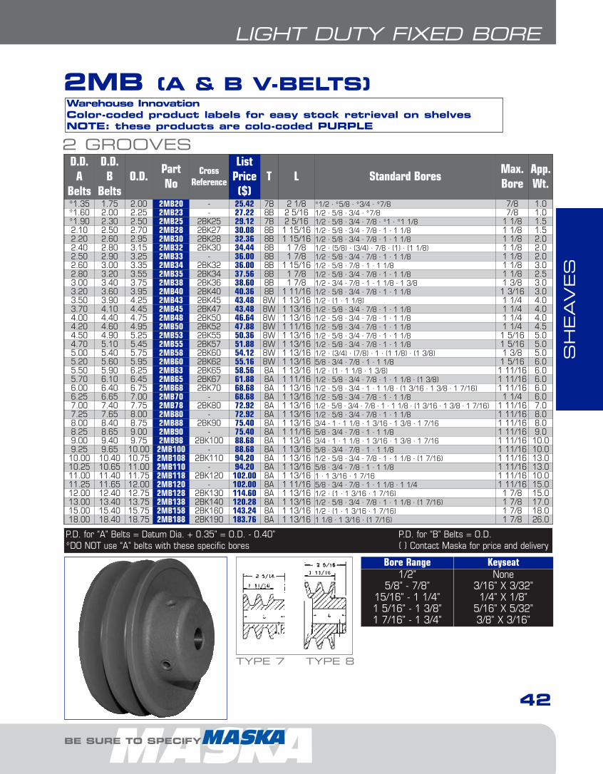
SH
EAVES
42
LIGHT DUTY FIXED BORE
BE SURE TO SPECIFY
Bore Range Keyseat1/2”
5/8” - 7/8”15/16” - 1 1/4”1 5/16” - 1 3/8”1 7/16” - 1 3/4”
None3/16” X 3/32”
1/4” X 1/8”5/16” X 5/32”3/8” X 3/16”
Warehouse InnovationColor-coded product labels for easy stock retrieval on shelvesNOTE: these products are colo-coded PURPLE
2 GROOVESD.D. A
Belts
D.D. B
BeltsO.D.
PartNo
CrossReference
ListPrice($)
T L Standard BoresMax.Bore
App.Wt.
*1.35 1.75 2.00 2MB20 - 25.42 7B 2 1/8 *1/2 · *5/8 · *3/4 · *7/8 7/8 1.0*1.60 2.00 2.25 2MB23 - 27.22 8B 2 5/16 1/2 · 5/8 · 3/4 · *7/8 7/8 1.0*1.90 2.30 2.50 2MB25 2BK25 29.12 7B 2 5/16 1/2 · 5/8 · 3/4 · 7/8 · *1 · *1 1/8 1 1/8 1.52.10 2.50 2.70 2MB28 2BK27 30.08 8B 1 15/16 1/2 · 5/8 · 3/4 · 7/8 · 1 · 1 1/8 1 1/8 1.52.20 2.60 2.95 2MB30 2BK28 32.36 8B 1 15/16 1/2 · 5/8 · 3/4 · 7/8 · 1 · 1 1/8 1 1/8 2.02.40 2.80 3.15 2MB32 2BK30 34.44 8B 1 7/8 1/2 · (5/8) · (3/4) · 7/8 · (1) · (1 1/8) 1 1/8 2.02.50 2.90 3.25 2MB33 - 36.00 8B 1 7/8 1/2 · 5/8 · 3/4 · 7/8 · 1 · 1 1/8 1 1/8 2.02.60 3.00 3.35 2MB34 2BK32 36.00 8B 1 15/16 1/2 · 5/8 · 7/8 · 1 · 1 1/8 1 1/8 3.02.80 3.20 3.55 2MB35 2BK34 37.56 8B 1 7/8 1/2 · 5/8 · 3/4 · 7/8 · 1 · 1 1/8 1 1/8 2.53.00 3.40 3.75 2MB38 2BK36 38.60 8B 1 7/8 1/2 · 3/4 · 7/8 · 1 · 1 1/8 · 1 3/8 1 3/8 3.03.20 3.60 3.95 2MB40 2BK40 40.36 8B 1 11/16 1/2 · 5/8 · 3/4 · 7/8 · 1 · 1 1/8 1 3/16 3.03.50 3.90 4.25 2MB43 2BK45 43.48 8W 1 13/16 1/2 · (1 · 1 1/8) 1 1/4 4.03.70 4.10 4.45 2MB45 2BK47 43.48 8W 1 13/16 1/2 · 5/8 · 3/4 · 7/8 · 1 · 1 1/8 1 1/4 4.04.00 4.40 4.75 2MB48 2BK50 46.64 8W 1 13/16 1/2 · 5/8 · 3/4 · 7/8 · 1 · 1 1/8 1 1/4 4.04.20 4.60 4.95 2MB50 2BK52 47.88 8W 1 11/16 1/2 · 5/8 · 3/4 · 7/8 · 1 · 1 1/8 1 1/4 4.54.50 4.90 5.25 2MB53 2BK55 50.36 8W 1 13/16 1/2 · 5/8 · 3/4 · 7/8 · 1 · 1 1/8 1 5/16 5.04.70 5.10 5.45 2MB55 2BK57 51.88 8W 1 13/16 1/2 · 5/8 · 3/4 · 7/8 · 1 · 1 1/8 1 5/16 5.05.00 5.40 5.75 2MB58 2BK60 54.12 8W 1 13/16 1/2 · (3/4) · (7/8) · 1 · (1 1/8) · (1 3/8) 1 3/8 5.05.20 5.60 5.95 2MB60 2BK62 55.16 8W 1 13/16 5/8 · 3/4 · 7/8 · 1 · 1 1/8 1 5/16 6.05.50 5.90 6.25 2MB63 2BK65 58.56 8A 1 13/16 1/2 · (1 · 1 1/8 · 1 3/8) 1 11/16 6.05.70 6.10 6.45 2MB65 2BK67 61.88 8A 1 11/16 1/2 · 5/8 · 3/4 · 7/8 · 1 · 1 1/8 · (1 3/8) 1 11/16 6.06.00 6.40 6.75 2MB68 2BK70 68.68 8A 1 13/16 1/2 · 5/8 · 3/4 · 1 · 1 1/8 · (1 3/16 · 1 3/8 · 1 7/16) 1 11/16 6.06.25 6.65 7.00 2MB70 - 68.68 8A 1 13/16 1/2 · 5/8 · 3/4 · 7/8 · 1 · 1 1/8 1 1/4 6.07.00 7.40 7.75 2MB78 2BK80 72.92 8A 1 13/16 1/2 · 5/8 · 3/4 · 7/8 · 1 · 1 1/8 · (1 3/16 · 1 3/8 · 1 7/16) 1 11/16 7.07.25 7.65 8.00 2MB80 - 72.92 8A 1 13/16 1/2 · 5/8 · 3/4 · 7/8 · 1 · 1 1/8 1 11/16 8.08.00 8.40 8.75 2MB88 2BK90 75.40 8A 1 13/16 3/4 · 1 · 1 1/8 · 1 3/16 · 1 3/8 · 1 7/16 1 11/16 8.08.25 8.65 9.00 2MB90 - 75.40 8A 1 11/16 5/8 · 3/4 · 7/8 · 1 · 1 1/8 1 11/16 9.09.00 9.40 9.75 2MB98 2BK100 88.68 8A 1 13/16 3/4 · 1 · 1 1/8 · 1 3/16 · 1 3/8 · 1 7/16 1 11/16 10.09.25 9.65 10.00 2MB100 - 88.68 8A 1 13/16 5/8 · 3/4 · 7/8 · 1 · 1 1/8 1 11/16 10.010.00 10.40 10.75 2MB108 2BK110 94.20 8A 1 13/16 1/2 · 5/8 · 3/4 · 7/8 · 1 · 1 1/8 · (1 7/16) 1 11/16 13.010.25 10.65 11.00 2MB110 - 94.20 8A 1 13/16 5/8 · 3/4 · 7/8 · 1 · 1 1/8 1 11/16 13.011.00 11.40 11.75 2MB118 2BK120 102.00 8A 1 13/16 1 · 1 3/16 · 1 7/16 1 11/16 10.011.25 11.65 12.00 2MB120 - 102.00 8A 1 11/16 5/8 · 3/4 · 7/8 · 1 · 1 1/8 · 1 1/4 1 11/16 15.012.00 12.40 12.75 2MB128 2BK130 114.60 8A 1 13/16 1/2 · (1 · 1 3/16 · 1 7/16) 1 7/8 15.013.00 13.40 13.75 2MB138 2BK140 120.28 8A 1 13/16 1/2 · 5/8 · 3/4 · 7/8 · 1 · 1 1/8 · (1 7/16) 1 7/8 17.015.00 15.40 15.75 2MB158 2BK160 143.24 8A 1 13/16 1/2 · (1 · 1 3/16 · 1 7/16) 1 7/8 18.018.00 18.40 18.75 2MB188 2BK190 183.76 8A 1 13/16 1 1/8 · 1 3/16 · (1 7/16) 1 7/8 26.0
P.D. for “A” Belts = Datum Dia. + 0.35” = O.D. - 0.40” P.D. for “B” Belts = O.D.*DO NOT use “A” belts with these specific bores ( ) Contact Maska for price and delivery
TYPE 7 TYPE 8
2MB (A & B V-BELTS)
2-FHP Sheaves1.13.qxp 2009-03-19 14:05 Page 13

SH
EAVES
MAL (A & 3L-4L V-BELTS)This entire product series uses the “L” Bushing
43
LIGHT DUTY BUSH TYPE
FOR DEPENDABLE DRIVE COMPONENTS, BE SURE TO SPECIFY
1 GROOVED.D
O.D.PartNo
CrossRefer.
ListPrice
$Type
Dimensions*Wt
(lbs)(3L)Belts
A(4L)Belts
E F L M
2.46 2.8 3.05 MAL30 AK30H 19.06 1B 3/8 3/4 1 11/32 31/32 1.152.66 3.0 3.25 MAL32 AK32H 19.36 1B 3/8 3/4 1 11/32 31/32 1.302.86 3.2 3.45 MAL34 AK34H 19.64 1B 3/32 3/4 1 11/32 11/16 1.203.16 3.5 3.75 MAL37 AK39H 20.78 1B 3/32 3/4 1 11/32 11/16 1.503.36 3.7 3.95 MAL39 AK41H 21.06 1B 3/32 3/4 1 11/32 11/16 1.753.66 4.0 4.25 MAL42 AK44H 21.34 1B 3/32 3/4 1 11/32 11/16 2.053.86 4.2 4.45 MAL44 AK46H 21.62 1B 3/32 3/4 1 11/32 11/16 2.254.16 4.5 4.75 MAL47 AK49H 21.92 3W 3/32 3/4 1 11/32 11/16 2.104.36 4.7 4.95 MAL49 AK51H 22.20 3W 3/32 3/4 1 11/32 11/16 2.354.66 5.0 5.25 MAL52 AK54H 22.48 3W 3/32 3/4 1 11/32 11/16 2.654.86 5.2 5.45 MAL54 AK56H 22.80 3W 3/32 3/4 1 11/32 11/16 2.755.16 5.5 5.75 MAL57 AK59H 23.24 5A 3/32 3/4 1 11/32 11/16 2.605.36 5.7 5.95 MAL59 AK61H 23.72 5A 3/32 3/4 1 11/32 11/16 2.505.66 6.0 6.25 MAL62 AK64H 24.32 5A 3/32 3/4 1 11/32 11/16 2.605.86 6.2 6.45 MAL64 AK66H 25.08 5A 3/32 3/4 1 11/32 11/16 2.706.16 6.5 6.75 MAL67 AK69H 27.48 5A 3/32 3/4 1 11/32 11/16 2.856.36 6.7 6.95 MAL69 AK71H 28.96 5A 3/32 3/4 1 11/32 11/16 2.906.66 7.0 7.25 MAL72 AK74H 30.36 5A 3/32 3/4 1 11/32 11/16 3.107.16 7.5 7.75 MAL77 AK79H 33.08 5A 3/32 3/4 1 11/32 11/16 3.357.66 8.0 8.25 MAL82 AK84H 35.20 5A 1/8 3/4 1 11/32 23/32 3.858.16 8.5 8.75 MAL87 AK89H 37.92 5A 3/32 3/4 1 11/32 11/16 4.108.66 9.0 9.25 MAL92 AK94H 40.96 5A 3/32 3/4 1 11/32 11/16 4.409.16 9.5 9.75 MAL97 AK99H 43.52 5A 3/32 3/4 1 11/32 11/16 4.609.66 10.0 10.25 MAL102 AK104H 44.12 5A 3/32 3/4 1 11/32 11/16 4.9010.16 10.5 10.75 MAL107 AK109H 46.36 5A 3/32 3/4 1 11/32 11/16 5.2010.66 11.0 11.25 MAL112 AK114H 47.84 5A 3/32 3/4 1 11/32 11/32 5.5511.66 12.0 12.25 MAL122 AK124H 52.28 5A 3/32 3/4 1 11/32 11/16 5.9012.66 13.0 13.25 MAL132 AK134H 60.28 5A 3/32 3/4 1 11/32 11/16 6.5513.66 14.0 14.25 MAL142 AK144H 67.72 5A 3/32 3/4 1 11/32 11/16 7.3014.66 15.0 15.25 MAL152 AK154H 74.52 5A 3/32 3/4 1 11/32 11/16 9.8017.66 18.0 18.25 MAL182 AK184H 88.00 5A 3/32 3/4 1 11/32 11/16 9.95
Warehouse InnovationColor-coded product labels for easy stock retrieval on shelvesNOTE: these products are colo-coded YELLOW
TYPE 1
TYPE 3
TYPE 5
P.D. for “A” (4L) Belts = O.D. P.D. for “3L” Belts = D.D.+0.25 = O.D.-0.34 * Dimensions to closest fractionLegend: “E” and “M” dimensions may vary according to shaft tolerance. With “L” bushing only reverse mounting ispossible, see page 11 for installation instructions.
2-FHP Sheaves1.13.qxp 2009-03-19 14:05 Page 14
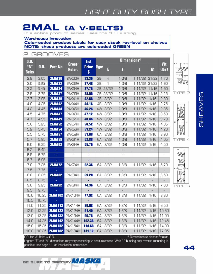
SH
EAVES
44
LIGHT DUTY BUSH TYPE
BE SURE TO SPECIFY
2 GROOVESD.D.“A”
BeltsO.D. Part No
CrossRefer.
ListPrice
$Type
Dimensions*Wt
(lbs)E F L M
2.8 3.05 2MAL30 2AK30H 33.36 2B 1 1 3/8 1 11/32 31/32 1.703.0 3.25 2MAL32 2AK32H 37.48 2B 1 1 3/8 1 11/32 31/32 1.903.2 3.45 2MAL34 2AK34H 37.76 2B 23/32 1 3/8 1 11/32 11/16 1.903.5 3.75 2MAL37 2AK39H 38.56 2B 23/32 1 3/8 1 11/32 11/16 2.153.7 3.95 2MAL39 2AK41H 42.68 4B 3/32 1 3/8 1 11/32 1/16 2.304.0 4.25 2MAL42 2AK44H 44.16 4B 3/32 1 3/8 1 11/32 1/16 2.754.2 4.45 2MAL44 2AK46H 46.24 4W 3/32 1 3/8 1 11/32 1/16 2.854.5 4.75 2MAL47 2AK49H 47.12 4W 3/32 1 3/8 1 11/32 1/16 3.504.7 4.95 2MAL49 2AK51H 48.44 4W 3/32 1 3/8 1 11/32 1/16 3.705.0 5.25 2MAL52 2AK54H 50.52 4W 3/32 1 3/8 1 11/32 1/16 4.055.2 5.45 2MAL54 2AK56H 51.24 4W 3/32 1 3/8 1 11/32 1/16 4.205.5 5.75 2MAL57 2AK59H 51.68 6A 3/32 1 3/8 1 11/32 1/16 3.905.7 5.95 2MAL59 2AK61H 52.88 6A 3/32 1 3/8 1 11/32 1/16 4.056.0 6.25 2MAL62 2AK64H 55.76 6A 3/32 1 3/8 1 11/32 1/16 4.506.2 6.45 - - - - - - - - -6.5 6.75 - - - - - - - - -6.7 6.95 - - - - - - - - -7.0 7.25 2MAL72 2AK74H 62.36 6A 3/32 1 3/8 1 11/32 1/16 5.707.5 7.75 - - - - - - - - -8.0 8.25 2MAL82 2AK84H 69.20 6A 3/32 1 3/8 1 11/32 1/16 6.508.5 8.75 - - - - - - - - -9.0 9.25 2MAL92 2AK94H 74.36 6A 3/32 1 3/8 1 11/32 1/16 7.809.5 9.75 - - - - - - - - -10.0 10.25 2MAL102 2AK104H 77.92 6A 3/32 1 3/8 1 11/32 1/16 8.8010.5 10.75 - - - - - - - - -11.0 11.25 2MAL112 2AK114H 86.68 6A 3/32 1 3/8 1 11/32 1/16 9.5012.0 12.25 2MAL122 2AK124H 91.40 6A 3/32 1 3/8 1 11/32 1/16 10.6013.0 13.25 2MAL132 2AK134H 96.76 6A 3/32 1 3/8 1 11/32 1/16 11.9014.0 14.25 2MAL142 2AK144H 102.36 6A 3/32 1 3/8 1 11/32 1/16 12.4515.0 15.25 2MAL152 2AK154H 114.68 6A 3/32 1 3/8 1 11/32 1/16 14.0018.0 18.25 2MAL182 2AK184H 151.12 6A 3/32 1 3/8 1 11/32 1/16 17.95
P.D. for “A” Belts = O.D. * Dimensions to closest fractionLegend: “E” and “M” dimensions may vary according to shaft tolerance. With “L” bushing only reverse mounting ispossible, see page 11 for installation instructions.
Warehouse InnovationColor-coded product labels for easy stock retrieval on shelvesNOTE: these products are colo-coded GREEN
2MAL (A V-BELTS)This entire product series uses the “L” Bushing
TYPE 2
TYPE 4
TYPE 6
2-FHP Sheaves1.13.qxp 2009-03-19 14:05 Page 15

SH
EAVES
45
LIGHT DUTY BUSH TYPE
FOR DEPENDABLE DRIVE COMPONENTS, BE SURE TO SPECIFY
1 GROOVED.D
O.D.PartNo
CrossRefer.
ListPrice
$Type
Dimensions*Wt
(lbs)A(4L)Belts
B(5L)Belts
E F L M
2.40 2.80 3.15 MBL31 BK30H 21.68 1B 17/32 29/32 1 11/32 63/64 1.252.60 3.00 3.35 MBL33 BK32H 23.06 1B 17/32 29/32 1 11/32 63/64 1.402.80 3.20 3.55 MBL35 BK34H 23.10 1B 17/32 29/32 1 11/32 63/64 1.653.00 3.40 3.75 MBL37 BK36H 23.28 3B 3/32 29/32 1 11/32 17/32 1.403.20 3.60 3.95 MBL39 BK40H 23.34 3B 3/32 29/32 1 11/32 17/32 1.703.50 3.90 4.25 MBL42 BK45H 23.84 3B 3/32 29/32 1 11/32 17/32 2.053.70 4.10 4.45 MBL44 BK47H 24.36 3B 3/32 29/32 1 11/32 17/32 2.354.00 4.40 4.75 MBL47 BK50H 24.92 3W 3/32 29/32 1 11/32 17/32 1.954.20 4.60 4.95 MBL49 BK52H 25.44 3W 3/32 29/32 1 11/32 17/32 2.404.50 4.90 5.25 MBL52 BK55H 25.96 3W 3/32 29/32 1 11/32 17/32 2.354.70 5.10 5.45 MBL54 BK57H 26.46 3W 3/32 29/32 1 11/32 17/32 2.905.00 5.40 5.75 MBL57 BK60H 26.76 5A 3/32 29/32 1 11/32 17/32 2.455.20 5.60 5.95 MBL59 BK62H 28.20 5A 3/32 29/32 1 11/32 17/32 2.805.50 5.90 6.25 MBL62 BK65H 30.08 5A 3/32 29/32 1 11/32 17/32 2.705.70 6.10 6.45 MBL64 BK67H 30.96 5A 3/32 29/32 1 11/32 17/32 2.806.00 6.40 6.75 MBL67 BK70H 32.04 5A 3/32 29/32 1 11/32 17/32 3.006.20 6.60 6.95 MBL69 BK72H 33.52 5A 3/32 29/32 1 11/32 17/32 3.606.50 6.90 7.25 MBL72 BK75H 34.92 5A 3/32 29/32 1 11/32 17/32 3.456.70 7.10 7.45 MBL74 BK77H 35.36 5A 3/32 29/32 1 11/32 17/32 3.657.00 7.40 7.75 MBL77 BK80H 35.96 5A 3/32 29/32 1 11/32 17/32 3.807.50 7.90 8.25 MBL82 BK85H 39.92 5A 3/32 29/32 1 11/32 17/32 4.558.00 8.40 8.75 MBL87 BK90H 42.48 5A 3/32 29/32 1 11/32 17/32 5.108.50 8.90 9.25 MBL92 BK95H 45.68 5A 3/32 29/32 1 11/32 17/32 5.309.00 9.40 9.75 MBL97 BK100H 47.44 5A 3/32 29/32 1 11/32 17/32 5.809.50 9.90 10.25 MBL102 BK105H 48.36 5A 3/32 29/32 1 11/32 17/32 5.5010.00 10.40 10.75 MBL107 BK110H 52.16 5A 3/32 29/32 1 11/32 17/32 5.8510.50 10.90 11.25 MBL112 BK115H 53.80 5A 3/32 29/32 1 11/32 17/32 7.2011.00 11.40 11.75 MBL117 BK120H 57.72 5A 3/32 29/32 1 11/32 17/32 6.5912.00 12.40 12.75 MBL127 BK130H 63.16 5A 3/32 29/32 1 11/32 17/32 7.9013.00 13.40 13.75 MBL137 BK140H 71.64 5A 3/32 29/32 1 11/32 17/32 10.1514.00 14.40 14.75 MBL147 BK150H 77.80 5A 3/32 29/32 1 11/32 17/32 13.2515.00 15.40 15.75 MBL157 BK160H 83.72 5A 3/32 29/32 1 11/32 17/32 16.0518.00 18.40 18.75 MBL187 BK190H 114.52 5A 3/32 29/32 1 11/32 17/32 12.45
Warehouse InnovationColor-coded product labels for easy stock retrieval on shelvesNOTE: these products are colo-coded RED
MBL (A-B & 4L-5L V-BELTS)This entire product series uses the “L” Bushing
TYPE 1
TYPE 3
TYPE 5
P.D. for “A” (4L) Belts = Datum.Dia. + 0.35” = O.D. - 0.40” P.D. for “B” (5L) Belts = O.D.* Dimensions to closest fractionLegend: “E” and “M” dimensions may vary according to shaft tolerance.With “L” bushing only reverse mounting is possible, see page 11.
2-FHP Sheaves1.13.qxp 2009-03-19 14:05 Page 16

SH
EAVES
46
LIGHT DUTY BUSH TYPE
BE SURE TO SPECIFY
2 GROOVESD.D
O.D. Part NoCrossRefer.
ListPrice
$Type
Dimensions*Wt
(lbs)“A”
Belts“B”
BeltsE F L M
2.40 2.80 3.15 - - - - - - - - -2.60 3.00 3.35 2MBL33 2BK32H 39.56 2B 1 3/8 1 3/4 1 11/32 31/32 2.352.80 3.20 3.55 2MBL35 2BK34H 39.84 2B 1 3/8 1 3/4 1 11/32 31/32 2.553.00 3.40 3.75 2MBL37 2BK36H 40.64 2B 1 3/8 1 3/4 1 11/32 31/32 3.003.20 3.60 3.95 2MBL39 2BK40H 41.04 2B 15/16 1 3/4 1 11/32 17/32 2.803.50 3.90 4.25 2MBL42 2BK45H 42.08 2B 15/16 1 3/4 1 11/32 17/32 3.253.70 4.10 4.45 2MBL44 2BK47H 46.36 2B 15/16 1 3/4 1 11/32 17/32 3.354.00 4.40 4.75 2MBL47 2BK50H 47.24 4W 3/32 1 3/4 1 11/32 5/16 3.854.20 4.60 4.95 2MBL49 2BK52H 48.44 4W 3/32 1 3/4 1 11/32 5/16 4.004.50 4.90 5.25 2MBL52 2BK55H 52.44 4W 3/32 1 3/4 1 11/32 5/16 4.404.70 5.10 5.45 2MBL54 2BK57H 53.32 4W 3/32 1 3/4 1 11/32 5/16 4.955.00 5.40 5.75 2MBL57 2BK60H 54.52 4W 3/32 1 3/4 1 11/32 5/16 5.305.20 5.60 5.95 2MBL59 2BK62H 55.24 4W 3/32 1 3/4 1 11/32 5/16 5.805.50 5.90 6.25 2MBL62 2BK65H 59.56 6A 1/16 1 3/4 1 11/32 11/32 5.405.70 6.10 6.45 2MBL64 2BK67H 60.60 6A 1/16 1 3/4 1 11/32 11/32 5.856.00 6.40 6.75 2MBL67 2BK70H 62.24 6A 1/16 1 3/4 1 11/32 11/32 5.556.20 6.60 6.95 2MBL69 - 64.60 6A 1/16 1 3/4 1 11/32 11/32 6.656.50 6.90 7.25 - - - - - - - - -6.70 7.10 7.45 - - - - - - - - -7.00 7.40 7.75 2MBL77 2BK80H 72.28 6A 1/16 1 3/4 1 11/32 11/32 6.857.50 7.90 8.25 - - - - - - - - -8.00 8.40 8.75 2MBL87 2BK90H 73.64 6A 1/16 1 3/4 1 11/32 11/32 9.658.50 8.90 9.25 - - - - - - - - -9.00 9.40 9.75 2MBL97 2BK100H 85.48 6A 1/16 1 3/4 1 11/32 11/32 9.209.50 9.90 10.25 - - - - - - - - -10.00 10.40 10.75 2MBL107 2BK110H 92.60 6A 1/16 1 3/4 1 11/32 11/32 12.8010.50 10.90 11.25 - - - - - - - - -11.00 11.40 11.75 2MBL117 2BK120H 105.76 6A 1/16 1 3/4 1 11/32 11/32 14.6512.00 12.40 12.75 2MBL127 2BK130H 113.64 6A 1/16 1 3/4 1 11/32 11/32 14.1513.00 13.40 13.75 2MBL137 2BK140H 128.60 6A 1/16 1 3/4 1 11/32 11/32 14.9515.00 15.40 15.75 2MBL157 2BK160H 134.92 6A 1/16 1 3/4 1 11/32 11/32 18.7018.00 18.40 18.75 2MBL187 2BK190H 151.40 6A 1/16 1 3/4 1 11/32 11/32 24.20
P.D. for “A” Belts = Datum.Dia. + 0.35” = O.D. - 0.40” P.D. for “B” Belts = O.D.* Dimensions to closest fractionLegend: “E” and “M” dimensions may vary according to shaft tolerance.With “L” bushing only reverse mounting is possible, see page 11.
Warehouse InnovationColor-coded product labels for easy stock retrieval on shelvesNOTE: these products are colo-coded PURPLE
2MBL (A-B V-BELTS)This entire product series uses the “L” Bushing
TYPE 2
TYPE 4
TYPE 6
2-FHP Sheaves1.13.qxp 2009-03-19 14:05 Page 17

SH
EAVES
FRACTIONAL HORSEPOWERSERIES (F.H.P.): MFAL (FIXED BORE A &
4L V-BELT SERIES)
47
FRACTIONAL HORSEPOWER SERIES (F.H.P.)
FOR DEPENDABLE DRIVE COMPONENTS, BE SURE TO SPECIFY
EXAMPLE: MFAL104X3/4
M FAL
M: MASKA LIGHT DUTY FAMILY
FAL: FRACTIONAL HORSEPOWER SERIE
104: OUTSIDE DIAMETER (10")* (REFER TOTHE DIMENSIONS TABLE FOR EXACTVALUE)
X3/4: BORE SIZE (3/4")
HOW TO ORDER
104 X3/4
• Stock items include one set screw with standard keyseat
• Bulk packaged 10 per carton
• MFAM 144 bulk packaged 5 per carton
DID YOU KNOW THAT...
CAUTlON: DO NOT use “A” gripnotch belts ratings with MFALand MFAM sheaves.
IMPORTANT REMINDER
2-FHP Sheaves1.13.qxp 2009-04-01 11:23 Page 18

SH
EAVES
BE SURE TO SPECIFY
48
FRACTIONAL HORSEPOWER SERIES (F.H.P.)
DIMENSIONS
Part No.List
Price $
Diameter Stock Bores Dimensions Wt(lbs)Outside
D.D.A (4L)
5/8’’ 3/4’’ 7/8’’ 1’’ F L P C
MFAL54 14.88 4.93 4.78 x x (x) x 19/32 1 1/16 15/32 - 1.1
MFAL64 15.56 5.93 5.78 x x (x) x 19/32 1 1/16 15/32 - 1.5
MFAL74 17.76 6.93 6.78 x x (x) x 19/32 1 1/16 15/32 - 1.75
MFAL84 20.24 7.93 7.78 x x (x) x 19/32 1 1/16 15/32 - 2.2
MFAL94 25.56 8.93 8.78 - x (x) x 19/32 1 1/16 15/32 - 3.0
MFAL104 28.20 9.93 9.78 - x (x) x 19/32 1 1/16 15/32 - 2.7
MFAL114 31.20 10.93 10.78 - x (x) x 19/32 1 1/16 15/32 - 3.1
MFAL124 37.40 11.93 11.78 - x (x) x 19/32 1 1/16 15/32 - 3.5
MFAM144* 61.20 14.16 14.00 - - - x 11/16 1 3/32 13/32 1/32 5.2
Pitch Dia. for “A” (4L) belts = Datum Dia. +.26” = O.D. +.11” ( ) = Contact Maska for price and delivery*Note: This item is packaged 5 per carton.
Bore Range Keyseat
1/2”5/8” - 7/8”
15/16” - 1 1/4”
None3/16” X 3/32”1/4” X 1/8”
2-FHP Sheaves1.13.qxp 2009-03-19 14:05 Page 19

SH
EAVES
49
STEP PULLEYS
FOR DEPENDABLE DRIVE COMPONENTS, BE SURE TO SPECIFY
STEP PULLEYS: MAS
EXAMPLE: MAS62X1/2
M AS
M: MASKA LIGHT DUTY FAMILY
AS: STEP PULLEY SERIE
62: OUTSIDE DIAMETERS
THE FIRST DIGIT REPRESENTS THELARGEST OUTSIDE DIAMETER (6”)
THE SECOND DIGIT REPRESENTS THESMALLEST OUTSIDE DIAMETER (2”)
X1/2: BORE SIZE (1/2")
HOW TO ORDER
62 X1/2
• Commonly used with drill presses & wood lathes• All bores come with 2 set screws• Designed for A, 4L & 3L V-Belts• Models of 3 to 5 steps• From 2”-6” diameter
DID YOU KNOW THAT...
2-FHP Sheaves1.13.qxp 2009-03-19 14:05 Page 20
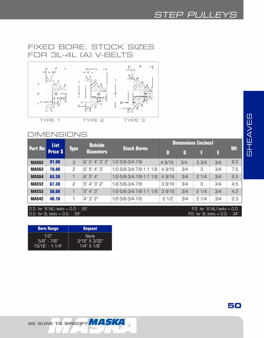
SH
EAVES
50
STEP PULLEYS
BE SURE TO SPECIFY
FIXED BORE, STOCK SIZESFOR 3L-4L (A) V-BELTS
TYPE 1 TYPE 2 TYPE 3
D.D. for “A”(4L) belts = O.D. - .25” P.D. for “A”(4L) belts = O.D.D.D. for 3L belts = O.D. - .59” P.D. for 3L belts = O.D. - .34”
Part NoList
Price $Type
OutsideDiameters
Stock BoresDimensions (inches)
WtD G F E
MAS62 91.80 3 6” 5” 4” 3” 2” 1/2-5/8-3/4-7/8 4 9/16 3/4 3 3/4 3/4 8.0
MAS63 78.80 2 6” 5” 4” 3” 1/2-5/8-3/4-7/8-1-1 1/8 4 9/16 3/4 3 3/4 7.5
MAS64 65.30 1 6” 5” 4” 1/2-5/8-3/4-7/8-1-1 1/8 4 9/16 3/4 2 1/4 3/4 6.5
MAS52 67.30 2 5” 4” 3” 2” 1/2-5/8-3/4-7/8 3 9/16 3/4 3 3/4 4.5
MAS53 56.60 1 5” 4” 3” 1/2-5/8-3/4-7/8-1-1 1/8 3 9/16 3/4 2 1/4 3/4 4.2
MAS42 46.10 1 4” 3” 2” 1/2-5/8-3/4-7/8 2 1/2 3/4 2 1/4 3/4 2.3
Bore Range Keyseat
1/2”5/8” - 7/8”
15/16” - 1-1/4”
None3/16” X 3/32”1/4” X 1/8”
DIMENSIONS
2-FHP Sheaves1.13.qxp 2009-03-19 14:05 Page 21

SH
EAVES
51
REDUCER BUSHINGS
FOR DEPENDABLE DRIVE COMPONENTS, BE SURE TO SPECIFY
REDUCER BUSHINGS
DIMENSIONS
I.D. O.D.Part No.
(Qty)List Price
Bag $Length
1/4 5/16 SB1 (10) 20.00 1
1/4 3/8 SB2 (10) 20.00 1 1/16
5/16 3/8 SB3 (10) 20.00 1 1/16
3/8 7/16 SB4 (10) 20.00 1 1/16
3/8 1/2 SB5 (10) 20.00 1
1/2 5/8 SB6 (10) 20.00 1 1/4
1/2 5/8 SB7 (10) 20.00 1 1/2
5/8 3/4 SB8 (10) 20.00 1 1/4
3/4 1 SB9 (10) 30.00 1 1/4
7/8 1 SB10 (10) 30.00 1 5/16
(Key) K10 (10) 20.00 1 1/4
Reducer bushings can be used to urgently accom-modate smaller shafts OR when you don't have therequired bore on hand.• Instantly adapt larger bores of various tools
(sheaves, gears, sprockets) to smaller diametershafts
• Keep these inexpensive items on hand for emer-gency situations to stay up and running
• Make local inventory more flexible at a very lowcost
• Split galvanized steel with 3/16” keyway slot• Sold poly-bagged in quantity of 10, no broken
package
DID YOU KNOW THAT...
EXAMPLE: SB1
SB1: PRODUCT NUMBER
HOW TO ORDER
SB1
2-FHP Sheaves1.13.qxp 2009-03-19 14:05 Page 22
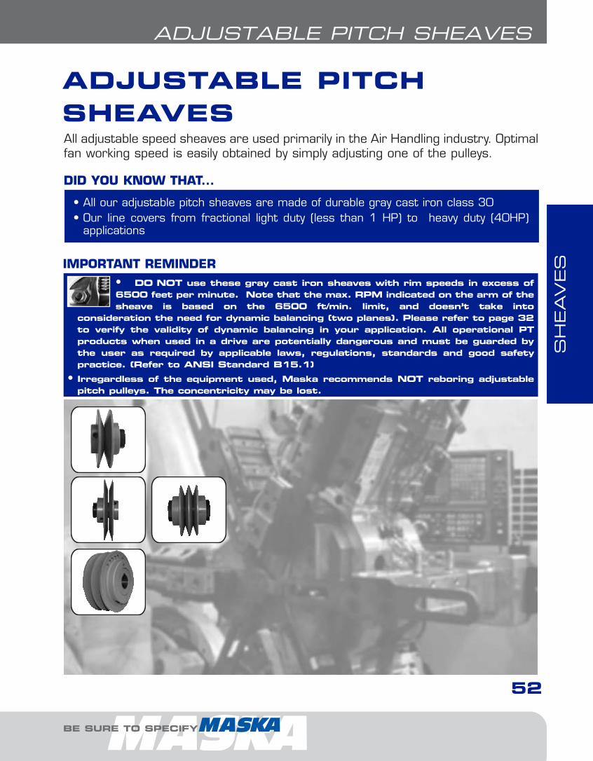
SH
EAVES
52
ADJUSTABLE PITCH SHEAVES
BE SURE TO SPECIFY
ADJUSTABLE PITCH SHEAVESAll adjustable speed sheaves are used primarily in the Air Handling industry. Optimalfan working speed is easily obtained by simply adjusting one of the pulleys.
• DO NOT use these gray cast iron sheaves with rim speeds in excess of6500 feet per minute. Note that the max. RPM indicated on the arm of thesheave is based on the 6500 ft/min. limit, and doesn’t take into
consideration the need for dynamic balancing (two planes). Please refer to page 32to verify the validity of dynamic balancing in your application. All operational PT products when used in a drive are potentially dangerous and must be guarded bythe user as required by applicable laws, regulations, standards and good safetypractice. (Refer to ANSI Standard B15.1)
• Irregardless of the equipment used, Maska recommends NOT reboring adjustablepitch pulleys. The concentricity may be lost.
IMPORTANT REMINDER
• All our adjustable pitch sheaves are made of durable gray cast iron class 30 • Our line covers from fractional light duty (less than 1 HP) to heavy duty (40HP)
applications
DID YOU KNOW THAT...
2-FHP Sheaves1.13.qxp 2009-03-19 14:05 Page 23
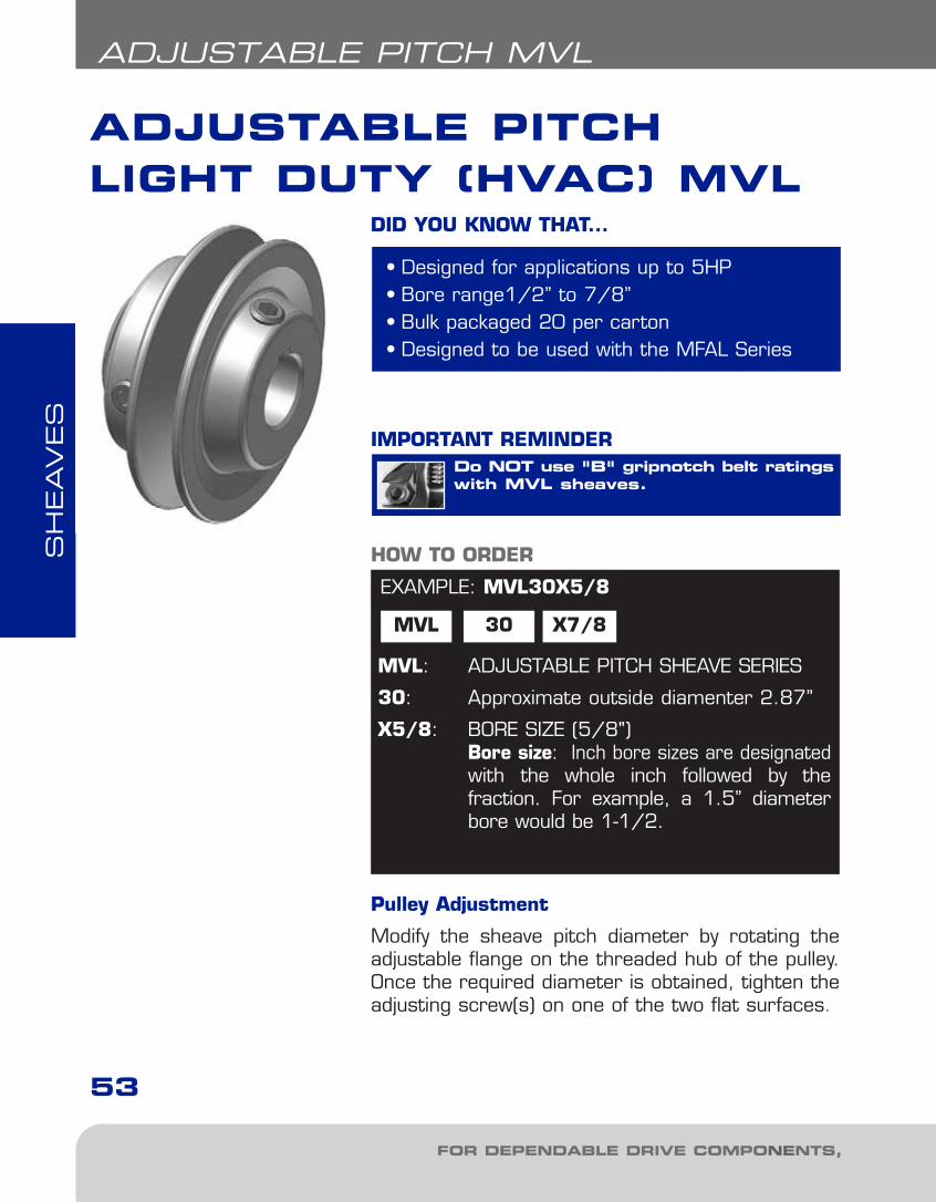
SH
EAVES
FOR DEPENDABLE DRIVE COMPONENTS, BE SURE TO SPECIFY
ADJUSTABLE PITCHLIGHT DUTY (HVAC) MVL
53
ADJUSTABLE PITCH MVL
Do NOT use "B" gripnotch belt ratingswith MVL sheaves.
IMPORTANT REMINDER
EXAMPLE: MVL30X5/8
MVL 30 X7/8
MVL: ADJUSTABLE PITCH SHEAVE SERIES
30: Approximate outside diamenter 2.87”
X5/8: BORE SIZE (5/8")Bore size: Inch bore sizes are designatedwith the whole inch followed by the fraction. For example, a 1.5” diameterbore would be 1-1/2.
HOW TO ORDER
• Designed for applications up to 5HP• Bore range1/2” to 7/8”• Bulk packaged 20 per carton• Designed to be used with the MFAL Series
DID YOU KNOW THAT...
Pulley Adjustment
Modify the sheave pitch diameter by rotating theadjustable flange on the threaded hub of the pulley.Once the required diameter is obtained, tighten theadjusting screw(s) on one of the two flat surfaces.
3-Adj1.7.qxp 2009-03-19 14:05 Page 2
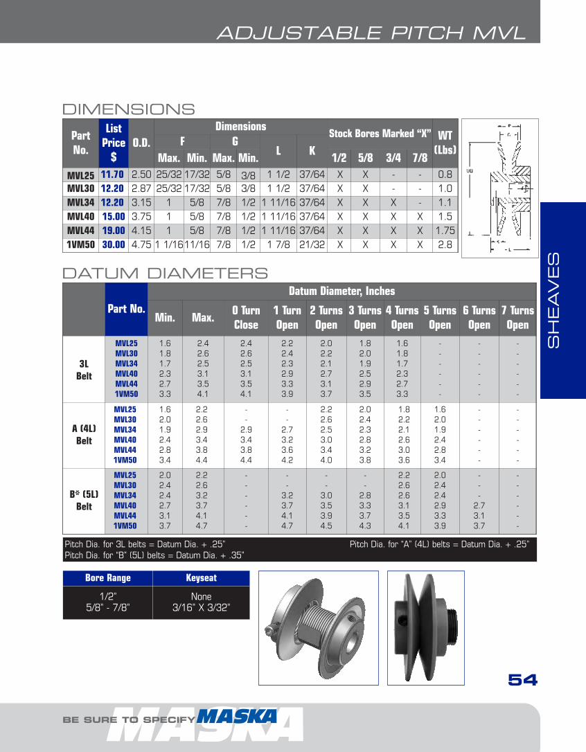
SH
EAVES
BE SURE TO SPECIFY
54
ADJUSTABLE PITCH MVL
Part No.Datum Diameter, Inches
Min. Max.0 TurnClose
1 TurnOpen
2 TurnsOpen
3 TurnsOpen
4 TurnsOpen
5 TurnsOpen
6 TurnsOpen
7 TurnsOpen
3LBelt
MVL25MVL30MVL34MVL40MVL441VM50
1.61.81.72.32.73.3
2.42.62.53.13.54.1
2.42.62.53.13.54.1
2.22.42.32.93.33.9
2.02.22.12.73.13.7
1.82.01.92.52.93.5
1.61.81.72.32.73.3
------
------
------
A (4L)Belt
MVL25MVL30MVL34MVL40MVL441VM50
1.62.01.92.42.83.4
2.22.62.93.43.84.4
--
2.93.43.84.4
--
2.73.23.64.2
2.22.62.53.03.44.0
2.02.42.32.83.23.8
1.82.22.12.63.03.6
1.62.01.92.42.83.4
------
------
B* (5L)Belt
MVL25MVL30MVL34MVL40MVL441VM50
2.02.42.42.73.13.7
2.22.63.23.74.14.7
------
--
3.23.74.14.7
--
3.03.53.94.5
--
2.83.33.74.3
2.22.62.63.13.54.1
2.02.42.42.93.33.9
---
2.73.13.7
------
Bore Range Keyseat
1/2”5/8” - 7/8”
None3/16” X 3/32”
DIMENSIONS
PartNo.
ListPrice
$O.D.
DimensionsStock Bores Marked “X” WT
(Lbs)F G
L KMax. Min. Max. Min. 1/2 5/8 3/4 7/8
MVL25 11.70 2.50 25/32 17/32 5/8 3/8 1 1/2 37/64 X X - - 0.8MVL30 12.20 2.87 25/32 17/32 5/8 3/8 1 1/2 37/64 X X - - 1.0MVL34 12.20 3.15 1 5/8 7/8 1/2 1 11/16 37/64 X X X - 1.1MVL40 15.00 3.75 1 5/8 7/8 1/2 1 11/16 37/64 X X X X 1.5MVL44 19.00 4.15 1 5/8 7/8 1/2 1 11/16 37/64 X X X X 1.751VM50 30.00 4.75 1 1/1611/16 7/8 1/2 1 7/8 21/32 X X X X 2.8
Pitch Dia. for 3L belts = Datum Dia. + .25” Pitch Dia. for “A” (4L) belts = Datum Dia. + .25”Pitch Dia. for “B” (5L) belts = Datum Dia. + .35”
DATUM DIAMETERS
3-Adj1.7.qxp 2009-03-19 14:05 Page 3

SH
EAVES
FOR DEPENDABLE DRIVE COMPONENTS, BE SURE TO SPECIFY
8000 SERIES
55
ADJUSTABLE PITCH 8000 SERIES
Applications with a speed superior to5000 ft./min. may require more accurate balancing.
Specify sheave and required bore diameterwhen ordering.
IMPORTANT REMINDER
Pulley Adjustment
Modify the sheave pitch diameter by rotating theadjustable flange on the threaded hub of the pulley.Once the required diameter is obtained, tighten theadjusting screw(s) on one of the two flat surfaces.
To obtain the same pitch diameter in both groovesof the D8000 series, tighten both movable flangesagainst the central flange, make trace marks onboth flanges, then rotate both flanges the samenumber of turns.
• Stock Sizes - 1 and 2 grooves up to 25 HP• Both 1 and 2 groove adjustable sheaves permit
variations of as much as 30% in speed whenused with a fixed diameter sheave
• Detailed Cross-Over Chart on pages 185-186• Available in metric bores• Larger sizes come with 2 set screws• Other special bores are available, call for
delivery terms
DID YOU KNOW THAT...
EXAMPLE: 8600X1-3/8
8600 X1-3/88600: ADJUSTABLE PITCH SHEAVE SIZE
The first digit stands for 8000 series. Lastthree digits represent the approximate outside diameter (6.00)
X1-3/8: BORE SIZE (1 3/8")Bore size: Metric bore sizes are designatedwith “MM” after the metric dimension (X 25MM). Inch bore sizes are designatedwith the whole inch followed by the fraction. For example, a 1.5” diameter borewould be 1-1/2.
HOW TO ORDER
3-Adj1.7.qxp 2009-03-19 14:05 Page 4
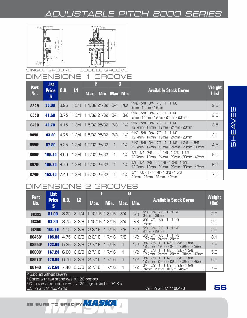
SH
EAVES
BE SURE TO SPECIFY
56
ADJUSTABLE PITCH 8000 SERIES
DIMENSIONS 1 GROOVEPartNo.
ListPrice
$O.D. L1
F GAvailable Stock Bores
Weight(lbs)Max. Min. Max. Min.
8325 33.80 3.25 1 3/4 1 1/32 21/32 3/4 3/8*1/2 · 5/8 · 3/4 · 7/8 · 1 · 1 1/89mm · 14mm · 19mm 2.0
8350 41.60 3.75 1 3/4 1 1/32 21/32 3/4 3/8 *1/2 · 5/8 · 3/4 · 7/8 · 1 · 1 1/89mm · 14mm · 19mm · 24mm · 28mm 2.0
8400 42.70 4.15 1 3/4 1 5/32 25/32 7/8 1/2 *1/2 · 5/8 · 3/4 · 7/8 · 1 · 1 1/812.7mm · 14mm · 19mm · 24mm · 28mm 2.5
84501 43.20 4.75 1 3/4 1 5/32 25/32 7/8 1/2 *1/2 · 5/8 · 3/4 · 7/8 · 1 · 1 1/812.7mm · 14mm · 19mm · 24mm · 28mm 3.1
85502 67.80 5.35 1 3/4 1 9/32 25/32 1 1/2 *1/2 · 5/8 · 3/4 · 7/8 · 1 · 1 1/8 · 1 3/8 · 1 5/812.7mm · 14mm · 19mm · 24mm · 28mm · 38mm 4.5
86002 105.40 6.00 1 3/4 1 9/32 25/32 1 1/2 5/8 · 3/4 · 7/8 · 1 · 1 1/8 · 1 3/8 · 1 5/812.7mm · 19mm · 24mm · 28mm · 38mm · 42mm 5.0
86702 106.80 6.70 1 3/4 1 9/32 25/32 1 1/2 5/8 · 3/4 · 7/8-1 · 1 1/8 · 1 3/8 · 1 5/812.7mm · 19mm · 24mm · 28mm · 38mm · 42mm 6.0
87402 153.40 7.40 1 3/4 1 9/32 25/32 1 1/2 3/4 · 7/8 · 1 · 1 1/8 · 1 3/8 · 1 5/824mm · 28mm · 38mm · 42mm 7.0
DIMENSIONS 2 GROOVESPartNo.
ListPrice
$O.D. L2
F GAvailable Stock Bores
Weight(lbs)Max. Min. Max. Min.
D8325 81.00 3.25 3 1/4 1 15/16 1 3/16 3/4 3/85/8 · 3/4 · 7/8 · 1 · 1 1/824mm · 28mm 2.0
D8350 93.20 3.75 3 3/8 1 15/16 1 3/16 3/4 3/8 5/8 · 3/4 · 7/8 · 1 · 1 1/828mm 2.0
D8400 100.30 4.15 3 3/8 2 3/16 1 7/16 7/8 1/2 5/8 · 3/4 · 7/8 · 1 · 1 1/824mm · 28mm 2.5
D84501 105.80 4.75 3 3/8 2 3/16 1 7/16 7/8 1/2 5/8 · 3/4 · 7/8 · 1 · 1 1/812.7mm · 24mm · 28mm 3.1
D85502 123.60 5.35 3 3/8 2 7/16 1 7/16 1 1/2 3/4 · 7/8 · 1 · 1 1/8 · 1 3/8 · 1 5/812.7mm · 19mm · 24mm · 28mm · 38mm 4.5
D86002 167.20 6.00 3 3/8 2 7/16 1 7/16 1 1/2 3/4 · 7/8 · 1 · 1 1/8 · 1 3/8 · 1 5/812.7mm · 24mm · 28mm · 38mm · 42mm 5.0
D86702 176.80 6.70 3 3/8 2 7/16 1 7/16 1 1/2 3/4 · 7/8 · 1 · 1 1/8 · 1 3/8 · 1 5/812.7mm · 24mm · 28mm · 38mm · 42mm 6.0
D87402 272.60 7.40 3 3/8 2 7/16 1 7/16 1 1/2 3/4 · 7/8 · 1 · 1 1/8 · 1 3/8 · 1 5/824mm · 28mm · 38mm · 42mm 7.0
* Supplied without keyway1 Comes with two set screws at 120 degrees² Comes with two set screws at 120 degrees and an ‘’H’’ KeyU.S. Patent Nº 450 4249 Can. Patent Nº 1160478
SINGLE GROOVE DOUBLE GROOVE
3-Adj1.7.qxp 2009-03-19 14:05 Page 5
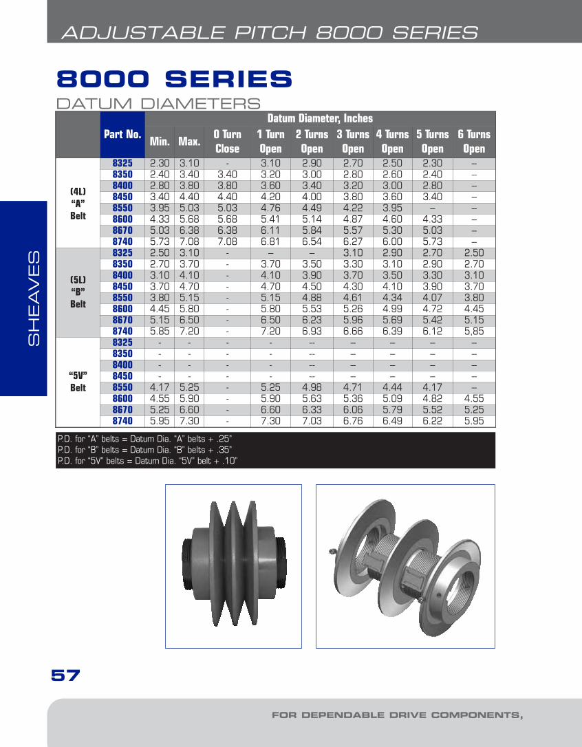
SH
EAVES
FOR DEPENDABLE DRIVE COMPONENTS, BE SURE TO SPECIFY
57
ADJUSTABLE PITCH 8000 SERIES
Part No.Datum Diameter, Inches
Min. Max.0 TurnClose
1 TurnOpen
2 TurnsOpen
3 TurnsOpen
4 TurnsOpen
5 TurnsOpen
6 TurnsOpen
(4L)“A”Belt
8325 2.30 3.10 - 3.10 2.90 2.70 2.50 2.30 –8350 2.40 3.40 3.40 3.20 3.00 2.80 2.60 2.40 –8400 2.80 3.80 3.80 3.60 3.40 3.20 3.00 2.80 –8450 3.40 4.40 4.40 4.20 4.00 3.80 3.60 3.40 –8550 3.95 5.03 5.03 4.76 4.49 4.22 3.95 – –8600 4.33 5.68 5.68 5.41 5.14 4.87 4.60 4.33 –8670 5.03 6.38 6.38 6.11 5.84 5.57 5.30 5.03 –8740 5.73 7.08 7.08 6.81 6.54 6.27 6.00 5.73 –
(5L)“B”Belt
8325 2.50 3.10 - – – 3.10 2.90 2.70 2.508350 2.70 3.70 - 3.70 3.50 3.30 3.10 2.90 2.708400 3.10 4.10 - 4.10 3.90 3.70 3.50 3.30 3.108450 3.70 4.70 - 4.70 4.50 4.30 4.10 3.90 3.708550 3.80 5.15 - 5.15 4.88 4.61 4.34 4.07 3.808600 4.45 5.80 - 5.80 5.53 5.26 4.99 4.72 4.458670 5.15 6.50 - 6.50 6.23 5.96 5.69 5.42 5.158740 5.85 7.20 - 7.20 6.93 6.66 6.39 6.12 5,85
“5V”Belt
8325 - - - - -- – – – –8350 - - - - -- – – – –8400 - - - - -- – – – –8450 - - - - -- – – – –8550 4.17 5.25 - 5.25 4.98 4.71 4.44 4.17 –8600 4.55 5.90 - 5.90 5.63 5.36 5.09 4.82 4.558670 5.25 6.60 - 6.60 6.33 6.06 5.79 5.52 5.258740 5.95 7.30 - 7.30 7.03 6.76 6.49 6.22 5.95
P.D. for “A” belts = Datum Dia. “A” belts + .25”P.D. for “B” belts = Datum Dia. “B” belts + .35”P.D. for “5V” belts = Datum Dia. “5V” belt + .10”
DATUM DIAMETERS8000 SERIES
3-Adj1.7.qxp 2009-03-19 14:05 Page 6
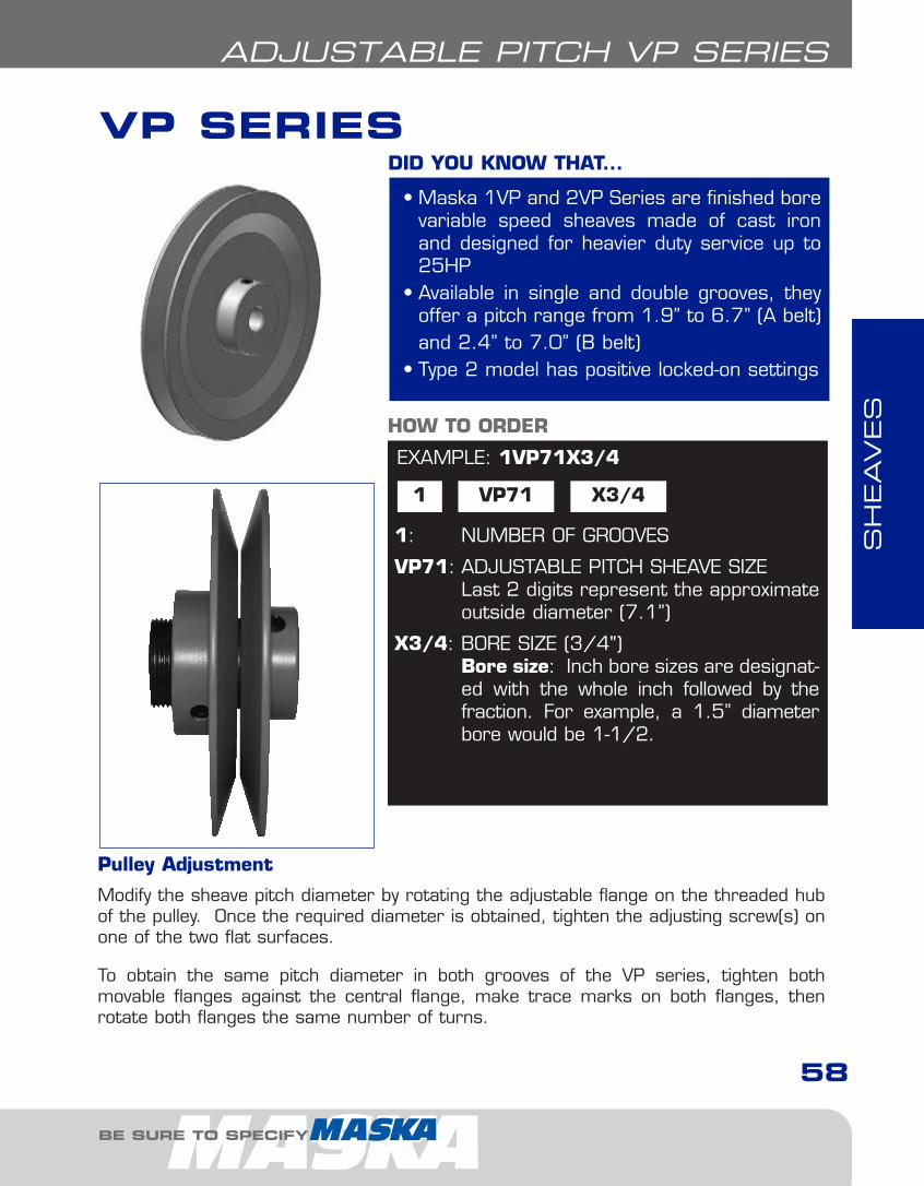
SH
EAVES
BE SURE TO SPECIFY
58
ADJUSTABLE PITCH VP SERIES
VP SERIES
• Maska 1VP and 2VP Series are finished borevariable speed sheaves made of cast ironand designed for heavier duty service up to25HP
• Available in single and double grooves, theyoffer a pitch range from 1.9” to 6.7” (A belt)and 2.4” to 7.0” (B belt)
• Type 2 model has positive locked-on settings
DID YOU KNOW THAT...
EXAMPLE: 1VP71X3/4
1 VP71
1: NUMBER OF GROOVES
VP71: ADJUSTABLE PITCH SHEAVE SIZELast 2 digits represent the approximateoutside diameter (7.1”)
X3/4: BORE SIZE (3/4")Bore size: Inch bore sizes are designat-ed with the whole inch followed by the fraction. For example, a 1.5” diameterbore would be 1-1/2.
HOW TO ORDER
X3/4
Pulley Adjustment
Modify the sheave pitch diameter by rotating the adjustable flange on the threaded hubof the pulley. Once the required diameter is obtained, tighten the adjusting screw(s) onone of the two flat surfaces.
To obtain the same pitch diameter in both grooves of the VP series, tighten both movable flanges against the central flange, make trace marks on both flanges, thenrotate both flanges the same number of turns.
3-Adj1.7.qxp 2009-03-19 14:05 Page 7
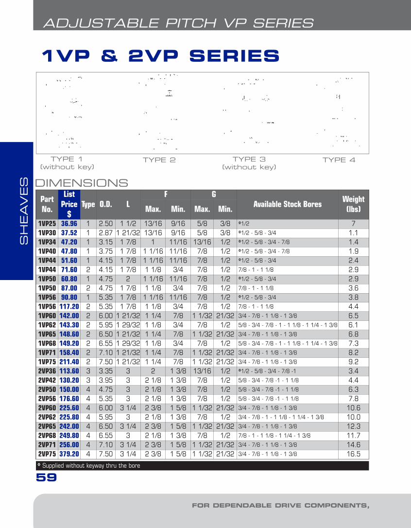
SH
EAVES
FOR DEPENDABLE DRIVE COMPONENTS, BE SURE TO SPECIFY
1VP & 2VP SERIES
59
ADJUSTABLE PITCH VP SERIES
DIMENSIONSPartNo.
ListPrice
$Type O.D. L
F GAvailable Stock Bores
Weight(lbs)Max. Min. Max. Min.
1VP25 36.96 1 2.50 1 1/2 13/16 9/16 5/8 3/8 *1/2 71VP30 37.52 1 2.87 1 21/32 13/16 9/16 5/8 3/8 *1/2 - 5/8 - 3/4 1.11VP34 47.20 1 3.15 1 7/8 1 11/16 13/16 1/2 *1/2 - 5/8 - 3/4 - 7/8 1.41VP40 47.80 1 3.75 1 7/8 1 1/16 11/16 7/8 1/2 *1/2 - 5/8 - 3/4 - 7/8 1.91VP44 51.60 1 4.15 1 7/8 1 1/16 11/16 7/8 1/2 *1/2 - 5/8 - 3/4 2.41VP44 71.60 2 4.15 1 7/8 1 1/8 3/4 7/8 1/2 7/8 - 1 - 1 1/8 2.91VP50 60.80 1 4.75 2 1 1/16 11/16 7/8 1/2 *1/2 - 5/8 - 3/4 2.91VP50 87.00 2 4.75 1 7/8 1 1/8 3/4 7/8 1/2 7/8 - 1 - 1 1/8 3.61VP56 90.80 1 5.35 1 7/8 1 1/16 11/16 7/8 1/2 *1/2 - 5/8 - 3/4 3.81VP56 117.20 2 5.35 1 7/8 1 1/8 3/4 7/8 1/2 7/8 - 1 - 1 1/8 4.41VP60 142.00 2 6.00 1 21/32 1 1/4 7/8 1 1/32 21/32 3/4 - 7/8 - 1 1/8 - 1 3/8 6.51VP62 143.30 2 5.95 1 29/32 1 1/8 3/4 7/8 1/2 5/8 - 3/4 - 7/8 - 1 - 1 1/8 - 1 1/4 - 1 3/8 6.11VP65 148.60 2 6.50 1 21/32 1 1/4 7/8 1 1/32 21/32 3/4 - 7/8 - 1 1/8 - 1 3/8 6.81VP68 149.20 2 6.55 1 29/32 1 1/8 3/4 7/8 1/2 5/8 - 3/4 - 7/8 - 1 - 1 1/8 - 1 1/4 - 1 3/8 7.31VP71 158.40 2 7.10 1 21/32 1 1/4 7/8 1 1/32 21/32 3/4 - 7/8 - 1 1/8 - 1 3/8 8.21VP75 211.40 2 7.50 1 21/32 1 1/4 7/8 1 1/32 21/32 3/4 - 7/8 - 1 1/8 - 1 3/8 9.22VP36 113.60 3 3.35 3 2 1 3/8 13/16 1/2 *1/2 - 5/8 - 3/4 - 7/8 -1 3.42VP42 130.20 3 3.95 3 2 1/8 1 3/8 7/8 1/2 5/8 - 3/4 - 7/8 -1 - 1 1/8 4.42VP50 150.00 4 4.75 3 2 1/8 1 3/8 7/8 1/2 5/8 - 3/4 - 7/8 -1 - 1 1/8 6.32VP56 176.60 4 5.35 3 2 1/8 1 3/8 7/8 1/2 5/8 - 3/4 - 7/8 -1 - 1 1/8 7.82VP60 225.60 4 6.00 3 1/4 2 3/8 1 5/8 1 1/32 21/32 3/4 - 7/8 - 1 1/8 - 1 3/8 10.62VP62 225.80 4 5.95 3 2 1/8 1 3/8 7/8 1/2 3/4 - 7/8 - 1 - 1 1/8 - 1 1/4 - 1 3/8 10.02VP65 242.00 4 6.50 3 1/4 2 3/8 1 5/8 1 1/32 21/32 3/4 - 7/8 - 1 1/8 - 1 3/8 12.32VP68 249.80 4 6.55 3 2 1/8 1 3/8 7/8 1/2 7/8 - 1 - 1 1/8 - 1 1/4 - 1 3/8 11.72VP71 256.00 4 7.10 3 1/4 2 3/8 1 5/8 1 1/32 21/32 3/4 - 7/8 - 1 1/8 - 1 3/8 14.62VP75 379.20 4 7.50 3 1/4 2 3/8 1 5/8 1 1/32 21/32 3/4 - 7/8 - 1 1/8 - 1 3/8 16.5
TYPE 1 (without key)
TYPE 3 (without key)
TYPE 4TYPE 2
* Supplied without keyway thru the bore
3-Adj1.7.qxp 2009-03-19 14:06 Page 8

SH
EAVES
BE SURE TO SPECIFY
ADJUSTABLE PITCH VP SERIES
DATUM DIAMETERS
Part No.Datum Diameter, Inches
Min. Max.0 TurnClose
1 TurnOpen
2 TurnsOpen
3 TurnsOpen
4 TurnsOpen
5 TurnsOpen
6 TurnsOpen
3LBelt
1VP251VP301VP342VP361VP402VP421VP441VP50 & 2VP501VP56 & 2VP561VP60 & 2VP601VP62 & 2VP621VP65 & 2VP651VP68 & 2VP681VP71 & 2VP711VP75 & 2VP75
1.61.81.71.92.32.52.73.33.9-
4.5-
5.1--
2.42.62.52.73.13.33.54.14.7-
5.3-
5.9--
2.42.62.52.73.13.33.54.14.7-
5.3-
5.9--
2.22.42.32.52.93.13.33.94.5-
5.1-
5.7--
2.02.22.12.32.72.93.13.74.3-
4.9-
5.5--
1.82.01.92.12.52.72.93.54.1-
4.7-
5.3--
1.61.81.71.92.32.52.73.33.9-
4.5-
5.1--
---------------
---------------
(4L) “A”Belt
1VP342VP361VP402VP421VP441VP50 & 2VP501VP56 & 2VP561VP60 & 2VP601VP62 & 2VP621VP65 & 2VP651VP68 & VP681VP71& 2VP711VP75 & 2VP75
1.92.02.42.62.83.44.04.24.64.75.25.35.7
2.93.03.43.63.84.45.05.25.65.76.26.36.7
2.93.03.43.63.84.45.05.25.65.76.26.36.7
2.72.83.23.43.64.24.85.05.45.56.06.16.5
2.52.63.03.23.44.04.64.85.25.35.85.96.3
2.32.42.83.03.23.84.44.65.05.15.65.76.1
2.12.22.62.83.03.64.24.44.84.95.45.55.9
1.92.02.42.62.83.44.04.24.64.75.25.35.7
-------------
(5L) “B”Belt
1VP342VP361VP402VP421VP441VP50 & 2VP501VP56 & 2VP561VP60 & 2VP601VP62 & 2VP621VP65 & 2VP651VP68 & 2VP681VP71 & 2VP711VP75 & 2VP75
2.42.52.72.93.13.74.34.34.94.85.55.45.8
3.23.33.73.94.14.75.35.55.96.06.56.67.0
-------
5.5-
6.0-
6.67.0
3.23.33.73.94.14.75.35.35.95.86.56.46.8
3.03.13.53.73.94.55.15.15.75.66.36.26.6
2.82.93.33.53.74.34.94.95.55.46.16.06.4
2.62.73.13.33.54.14.74.75.35.25.95.86.2
2.42.52.93.13.33.94.54.55.15.05.75.66.0
--
2.72.93.13.74.34.34.94.85.55.45.8
“5V”Belt
1VP342VP361VP402VP421VP441VP50 & 2VP501VP56 & 2VP561VP60 & 2VP601VP62 & 2VP621VP65 & 2VP651VP68 & 2VP681VP71 & 2VP711VP75 & 2VP75
--------
5.35.25.95.86.2
--------
6.36.46.97.07.4
---------
6.4-
7.07.4
--------
6.36.26.96.87.2
--------
6.16.06.76.67.0
--------
5.95.86.56.46.8
--------
5.75.66.36.26.6
--------
5.55.46.16.06.4
--------
5.35.25.95.86.2
P.D. for “3L” belts= Datum Dia. “3L” belts + .25”P.D. for “A” (4L) belts = Datum Dia. “A” belts + .25”
P.D. for “B” (5L) belts = Datum Dia. “B” belts + .35”P.D. for “5V” belts = Datum Dia. “5V” belts + .10”
60
3-Adj1.7.qxp 2009-03-19 14:06 Page 9
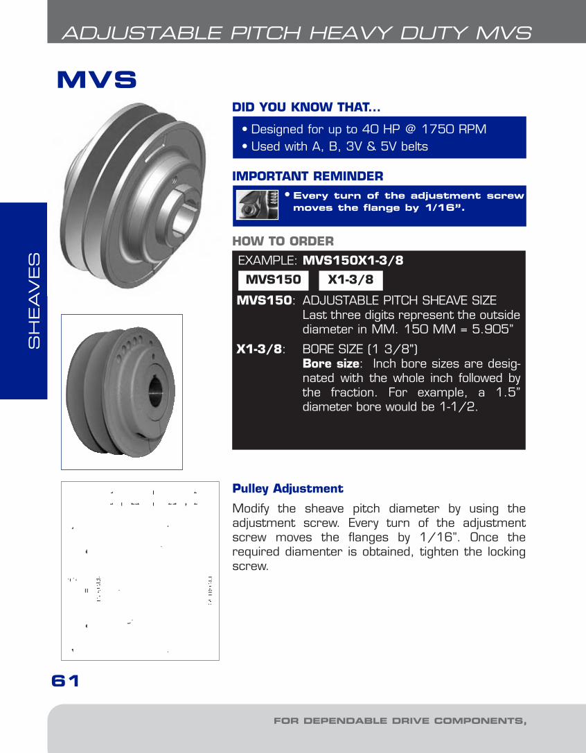
SH
EAVES
FOR DEPENDABLE DRIVE COMPONENTS, BE SURE TO SPECIFY
MVS
61
ADJUSTABLE PITCH HEAVY DUTY MVS
• Designed for up to 40 HP @ 1750 RPM• Used with A, B, 3V & 5V belts
DID YOU KNOW THAT...
EXAMPLE: MVS150X1-3/8
MVS150 X1-3/8
MVS150: ADJUSTABLE PITCH SHEAVE SIZELast three digits represent the outsidediameter in MM. 150 MM = 5.905”
X1-3/8: BORE SIZE (1 3/8")Bore size: Inch bore sizes are desig-nated with the whole inch followed bythe fraction. For example, a 1.5” diameter bore would be 1-1/2.
HOW TO ORDER
• Every turn of the adjustment screwmoves the flange by 1/16”.
IMPORTANT REMINDER
Pulley Adjustment
Modify the sheave pitch diameter by using theadjustment screw. Every turn of the adjustmentscrew moves the flanges by 1/16”. Once therequired diamenter is obtained, tighten the lockingscrew.
3-Adj1.7.qxp 2009-03-19 14:06 Page 10

SH
EAVES
BE SURE TO SPECIFY
62
ADJUSTABLE PITCH HEAVY DUTY MVS
Part No.List
Price$
O.D.Dimensions Stock Bores Marked “X”
WT(lbs)
F EL H 1 1/8 1 3/8 1 5/8 1 7/8 2 1/8
Min. Max. Min. Max.MVS130 228.00 5.118 1.73 2.27 0.75 1.02 3.77 3.15 X X - - - 8.5
MVS150 250.00 5.905 1.73 2.59 0.77 1.20 4.13 3.62 X X X - - 12.1
MVS170 272.00 6.692 1.73 2.59 0.77 1.20 4.13 3.62 X X X - - 14.8
MVS190 294.00 7.480 1.73 2.59 0.77 1.20 4.13 5.12 - X X X - 23.2
MVS210 316.00 8.268 1.73 2.59 0.77 1.20 4.13 5.12 - X X X X 27.0
MVS230 338.00 9.055 1.73 2.59 0.77 1.20 4.13 5.12 - X X X X 30.40
Part No.
Datum Diameter, Inches
Min. Max.0 TurnClose
1 TurnOpen
2 TurnsOpen
3 TurnsOpen
4 TurnsOpen
5 TurnsOpen
6 TurnsOpen
7 TurnsOpen
ABelt
MVS130MVS150MVS170MVS190MVS210MVS230
3.454.234.815.606.407.19
4.475.256.046.837.638.42
4.475.256.046.837.638.42
4.265.055.846.627.438.21
4.064.855.636.427.228.01
3.854.645.436.217.027.81
3.654.445.226.016.817.60
3.454.235.025.816.617.40
--
4.815.606.407.19
------
BBelt
MVS130MVS150MVS170MVS190MVS210MVS230
3.634.215.005.796.597.38
4.865.656.437.228.028.81
4.865.656.437.228.028.81
4.655.446.237.017.828.61
4.455.246.026.817.618.40
4.245.035.826.607.418.20
4.044.835.616.407.207.99
3.844.625.416.207.007.79
3.634.425.215.996.807.58
-4.215.005.796.597.38
3VBelt
MVS130MVS150MVS170MVS190MVS210MVS230
3.564.355.135.926.737.51
4.174.965.756.537.348.13
4.174.965.756.537.348.13
3.974.765.546.337.137.92
3.774.555.346.136.937.72
3.564.355.135.926.737.51
------
------
------
------
5VBelt
MVS130MVS150*MVS170*MVS190MVS210MVS230
-4.315.105.886.697.48
-5.746.537.328.128.91
-5.746.537.328.128.91
-5.546.337.117.928.70
-5.336.126.917.718.50
-5.135.926,707.518.29
-4.935.716.507.308.09
-4.725.516.297.107.89
-4.525.306.096.897.68
-4.315.105.886.697.48
* IMPORTANT: Recommended for use with narrow cog belts only.P.D. for “A” belt = Datum Dia. “A” belt + .25 P.D. for “B” belt= Datum Dia. “B” belt + .35P.D. for “3V” belts = Datum Dia. “3V” belts + .05 P.D. for “5V” belts = Datum Dia. “5V” belts + .10
DIMENSIONS
DATUM DIAMETERS
3-Adj1.7.qxp 2009-03-19 14:06 Page 11
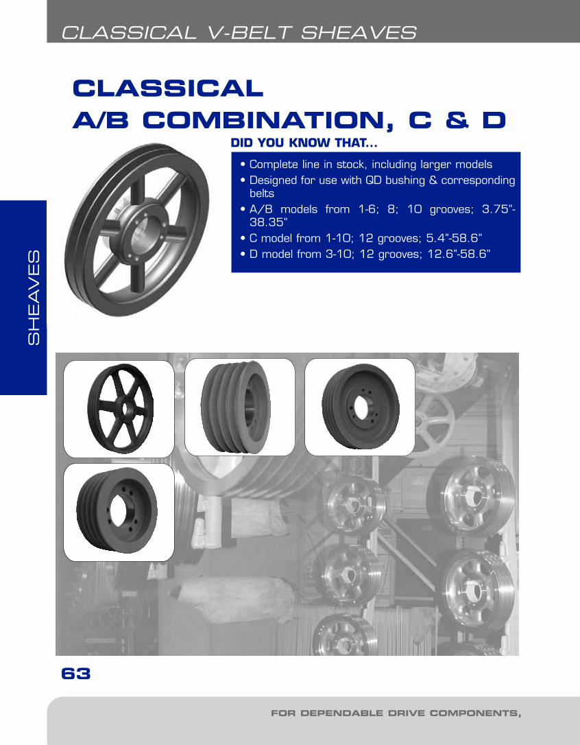
SH
EAVES
FOR DEPENDABLE DRIVE COMPONENTS, BE SURE TO SPECIFY
CLASSICAL A/B COMBINATION, C & D
63
CLASSICAL V-BELT SHEAVES
• Complete line in stock, including larger models• Designed for use with QD bushing & corresponding
belts• A/B models from 1-6; 8; 10 grooves; 3.75”-
38.35”• C model from 1-10; 12 grooves; 5.4”-58.6”• D model from 3-10; 12 grooves; 12.6”-58.6”
DID YOU KNOW THAT...
4-Class-narrow1.6.qxp 2009-03-19 14:07 Page 2

SH
EAVES
BE SURE TO SPECIFY
64
CLASSICAL V-BELT SHEAVES
EXAMPLE: 6B70
6 B
6: NUMBER OF GROOVESB: "A/B" COMBINATION SHEAVE SECTION70: DATUM DIAMETER FOR "B" BELTS (7.0")
HOW TO ORDER
70
• DO NOT use these gray cast iron sheaves with rimspeeds in excess of 6500 feet per minute. Note thatthe max. RPM indicated on the arm of the sheave is
based on the 6500 ft/min. limit, and doesn’t take into consideration the need for dynamic balancing (two planes).Please refer to the chart on page 32 to verify the validity ofdynamic balancing in your application.
All operational PT products when used in a drive are potentially dangerous and must be guarded by the user asrequired by applicable laws, regulations, standards and goodsafety practice. (Refer to ANSI Standard B15.1)
• When ordering a sheave to be dynamically balanced, youmust specify the sheave operational speed. Maska recom-mends ordering the matching bushing with the sheave toensure a balancing grade of 6.3. If the bushing is not orderedat the same time, a disclaimer will be sent to the customer discharging Maska from possible vibration problems relatedto the drive.
IMPORTANT REMINDER
NOTE:1 For mounting instructions with QD bushings, see page 11.2 All Charts: The type of sheave construction is indicated in the column entitled « T ». The
number refers to the drawing and the letter as follows: A = arms; B = block; W = web.3 "B" Column indicates the corresponding bushing size required.4 All dimensions are to the closest fraction.
4-Class-narrow1.6.qxp 2009-03-19 14:07 Page 3

SH
EAVES
FOR DEPENDABLE DRIVE COMPONENTS, BE SURE TO SPECIFY
“A/B” COMBINATION
65
CLASSICAL V-BELT SHEAVES
DIMENSIONS 1 GROOVEDatum dia.
O.D. Part NoList
Price$
F = 7/8 up to 7.15 O.D. & 1 inch thereafterA(4L)Belts
B(5L)Belts
H Type B L E Wt
3.0 3.4 3.75 1B341 26.00 5/8 11B SH 1 1/4 1/4 13.2 3.6 3.95 1B36 27.00 1/2 6B SH 1 1/4 1/8 13.4 3.8 4.15 1B38 28.00 1/2 6B SH 1 1/4 1/8 23.6 4.0 4.35 1B40 29.00 1/2 6B SH 1 1/4 1/8 23.8 4.2 4.55 1B42 30.00 1/2 6B SH 1 1/4 1/8 24.0 4.4 4.75 1B44 31.00 1/2 6B SH 1 1/4 1/8 24.2 4.6 4.95 1B46 32.00 7/16 7B SDS 1 5/16 0 24.4 4.8 5.15 1B48 33.00 7/16 7B SDS 1 5/16 0 34.6 5.0 5.35 1B50 34.00 7/16 7B SDS 1 5/16 0 34.8 5.2 5.55 1B52 35.00 7/16 7B SDS 1 5/16 0 35.0 5.4 5.75 1B54 36.00 7/16 7B SDS 1 5/16 0 45.2 5.6 5.95 1B56 37.00 7/16 7B SDS 1 5/16 0 45.4 5.8 6.15 1B58 38.00 7/16 7B SDS 1 5/16 0 45.6 6.0 6.35 1B60 40.00 7/16 7B SDS 1 5/16 0 55.8 6.2 6.55 1B62 42.00 7/16 7B SDS 1 5/16 0 56.0 6.4 6.75 1B64 44.00 7/16 7B SDS 1 5/16 0 66.2 6.6 6.95 1B66 48.00 7/16 7B SDS 1 5/16 0 66.4 6.8 7.15 1B68 50.00 7/16 7B SDS 1 5/16 0 66.6 7.0 7.35 1B70 52.00 9/16 6A SDS 1 5/16 1/4 67.0 7.4 7.75 1B74 56.00 9/16 6A SDS 1 5/16 1/4 67.6 8.0 8.35 1B80 58.00 9/16 6A SDS 1 5/16 1/4 78.2 8.6 8.95 1B86 62.00 9/16 6A SDS 1 5/16 1/4 88.6 9.0 9.35 1B90 63.00 9/16 6A SDS 1 5/16 1/4 99.0 9.4 9.75 1B94 64.00 9/16 6A SDS 1 5/16 1/4 910.6 11.0 11.35 1B110 76.00 9/16 6A SDS 1 5/16 1/4 1112.0 12.4 12.75 1B124 90.00 9/16 6A SDS 1 5/16 1/4 1213.2 13.6 13.95 1B136 96.00 9/16 6A SDS 1 5/16 1/4 1315.0 15.4 15.75 1B154 116.00 11/16 5A SK 1 7/8 3/16 2015.6 16.0 16.35 1B160 136.00 7/8 3A SK 1 7/8 0 2218.0 18.4 18.75 1B184 156.00 15/16 10A SK 1 7/8 1/16 2819.6 20.0 20.35 1B200 230.00 13/16 5A SK 1 7/8 1/16 3024.6 25.0 25.35 1B250 350.00 15/16 10A SK 1 7/8 1/16 40
TYPE 3
TYPE 10
P.D. for “A” (4L) Belts = Datum Dia. + .35” = O.D. - .40 P.D. for “B” (5L) Belts = O.D.1 Reverse mount only.
TYPE 5
TYPE 6
TYPE 7
4-Class-narrow1.6.qxp 2009-03-19 14:07 Page 4
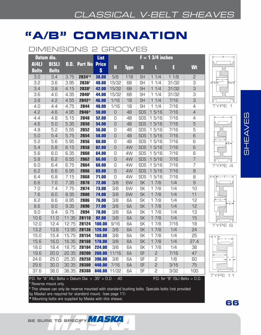
SH
EAVES
BE SURE TO SPECIFY
“A/B” COMBINATION
66
CLASSICAL V-BELT SHEAVES
DIMENSIONS 2 GROOVESDatum dia.
O.D. Part NoList
Price$
F = 1 3/4 inchesA(4L)Belts
B(5L)Belts
H Type B L E Wt
3.0 3.4 3.75 2B341* 38.00 5/8 11B SH 1 1/4 1 1/8 23.2 3.6 3.95 2B362 40.00 15/32 6B SH 1 1/4 31/32 33.4 3.8 4.15 2B382 42.00 15/32 6B SH 1 1/4 31/32 33.6 4.0 4.35 2B402 44.00 15/32 6B SH 1 1/4 31/32 33.8 4.2 4.55 2B42* 46.00 1/16 1B SH 1 1/4 7/16 34.0 4.4 4.75 2B44 48.00 1/16 1B SH 1 1/4 7/16 44.2 4.6 4.95 2B46* 50.00 0 4B SDS 1 5/16 7/16 44.4 4.8 5.15 2B48 52.00 0 4B SDS 1 5/16 7/16 44.6 5.0 5.35 2B50 54.00 0 4B SDS 1 5/16 7/16 54.8 5.2 5.55 2B52 56.00 0 4B SDS 1 5/16 7/16 55.0 5.4 5.75 2B54 58.00 0 4B SDS 1 5/16 7/16 65.2 5.6 5.95 2B56 60.00 0 4B SDS 1 5/16 7/16 65.4 5.8 6.15 2B58 62.00 0 4W SDS 1 5/16 7/16 65.6 6.0 6.35 2B60 64.00 0 4W SDS 1 5/16 7/16 65.8 6.2 6.55 2B62 66.00 0 4W SDS 1 5/16 7/16 76.0 6.4 6.75 2B64 68.00 0 4W SDS 1 5/16 7/16 76.2 6.6 6.95 2B66 69.00 0 4W SDS 1 5/16 7/16 86.4 6.8 7.15 2B68 71.00 0 4W SDS 1 5/16 7/16 86.6 7.0 7.35 2B70 72.00 3/8 6W SK 1 7/8 1/4 97.0 7.4 7.75 2B74 73.00 3/8 6W SK 1 7/8 1/4 107.6 8.0 8.35 2B80 74.00 3/8 6W SK 1 7/8 1/4 118.2 8.6 8.95 2B86 76.00 3/8 6A SK 1 7/8 1/4 128.6 9.0 9.35 2B90 77.00 3/8 6A SK 1 7/8 1/4 129.0 9.4 9.75 2B94 78.00 3/8 6A SK 1 7/8 1/4 1310.6 11.0 11.35 2B110 92.00 3/8 6A SK 1 7/8 1/4 1512.0 12.4 12.75 2B124 100.00 9/16 6A SK 1 7/8 7/16 1813.2 13.6 13.95 2B136 120.00 3/8 6A SK 1 7/8 1/4 2415.0 15.4 15.75 2B154 168.00 3/8 6A SK 1 7/8 1/4 2515.6 16.0 16.35 2B160 178.00 3/8 6A SK 1 7/8 1/4 27.418.0 18.4 18.75 2B184 224.00 3/8 6A SK 1 7/8 1/4 3819.6 20.0 20.35 2B200 260.00 11/16 6A SF 2 7/16 4724.6 25.0 25.35 2B250 396.00 3/8 6A SF 2 1/8 6029.6 30.0 30.35 2B300 440.00 7/16 6A SF 2 3/16 7537.6 38.0 38.35 2B380 840.00 11/32 6A SF 2 3/32 100
TYPE 1
TYPE 4
TYPE 11P.D. for “A” (4L) Belts = Datum Dia. + .35” = O.D. - .40 P.D. for “B” (5L) Belts = O.D.1 Reverse mount only.2 This sheave can only be reverse mounted with standard bushing bolts. Specials bolts (not providedby Maska) are required for standard mount. (see page 11)* Mounting bolts are supplied by Maska with this sheave.
TYPE 6
4-Class-narrow1.6.qxp 2009-03-19 14:07 Page 5
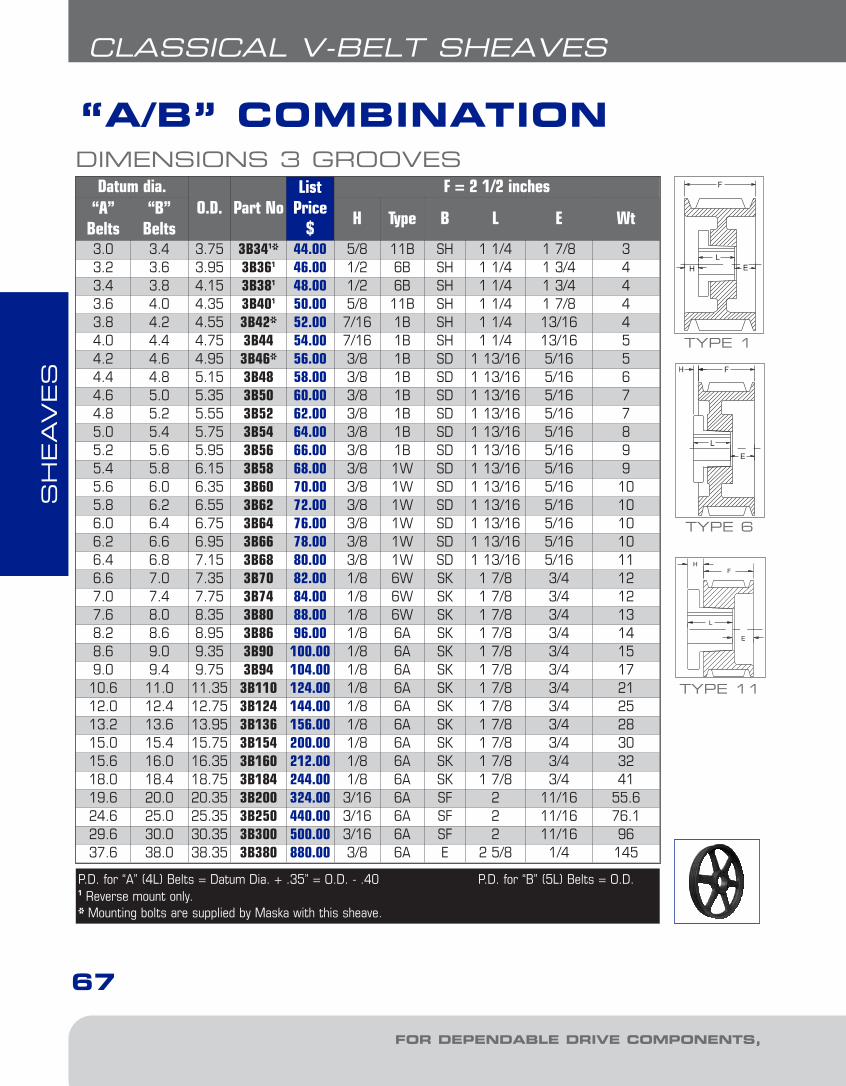
SH
EAVES
FOR DEPENDABLE DRIVE COMPONENTS, BE SURE TO SPECIFY
“A/B” COMBINATION
67
CLASSICAL V-BELT SHEAVES
DIMENSIONS 3 GROOVESDatum dia.
O.D. Part NoList
Price$
F = 2 1/2 inches“A”
Belts“B”
BeltsH Type B L E Wt
3.0 3.4 3.75 3B341* 44.00 5/8 11B SH 1 1/4 1 7/8 33.2 3.6 3.95 3B361 46.00 1/2 6B SH 1 1/4 1 3/4 43.4 3.8 4.15 3B381 48.00 1/2 6B SH 1 1/4 1 3/4 43.6 4.0 4.35 3B401 50.00 5/8 11B SH 1 1/4 1 7/8 43.8 4.2 4.55 3B42* 52.00 7/16 1B SH 1 1/4 13/16 44.0 4.4 4.75 3B44 54.00 7/16 1B SH 1 1/4 13/16 54.2 4.6 4.95 3B46* 56.00 3/8 1B SD 1 13/16 5/16 54.4 4.8 5.15 3B48 58.00 3/8 1B SD 1 13/16 5/16 64.6 5.0 5.35 3B50 60.00 3/8 1B SD 1 13/16 5/16 74.8 5.2 5.55 3B52 62.00 3/8 1B SD 1 13/16 5/16 75.0 5.4 5.75 3B54 64.00 3/8 1B SD 1 13/16 5/16 85.2 5.6 5.95 3B56 66.00 3/8 1B SD 1 13/16 5/16 95.4 5.8 6.15 3B58 68.00 3/8 1W SD 1 13/16 5/16 95.6 6.0 6.35 3B60 70.00 3/8 1W SD 1 13/16 5/16 105.8 6.2 6.55 3B62 72.00 3/8 1W SD 1 13/16 5/16 106.0 6.4 6.75 3B64 76.00 3/8 1W SD 1 13/16 5/16 106.2 6.6 6.95 3B66 78.00 3/8 1W SD 1 13/16 5/16 106.4 6.8 7.15 3B68 80.00 3/8 1W SD 1 13/16 5/16 116.6 7.0 7.35 3B70 82.00 1/8 6W SK 1 7/8 3/4 127.0 7.4 7.75 3B74 84.00 1/8 6W SK 1 7/8 3/4 127.6 8.0 8.35 3B80 88.00 1/8 6W SK 1 7/8 3/4 138.2 8.6 8.95 3B86 96.00 1/8 6A SK 1 7/8 3/4 148.6 9.0 9.35 3B90 100.00 1/8 6A SK 1 7/8 3/4 159.0 9.4 9.75 3B94 104.00 1/8 6A SK 1 7/8 3/4 1710.6 11.0 11.35 3B110 124.00 1/8 6A SK 1 7/8 3/4 2112.0 12.4 12.75 3B124 144.00 1/8 6A SK 1 7/8 3/4 2513.2 13.6 13.95 3B136 156.00 1/8 6A SK 1 7/8 3/4 2815.0 15.4 15.75 3B154 200.00 1/8 6A SK 1 7/8 3/4 3015.6 16.0 16.35 3B160 212.00 1/8 6A SK 1 7/8 3/4 3218.0 18.4 18.75 3B184 244.00 1/8 6A SK 1 7/8 3/4 4119.6 20.0 20.35 3B200 324.00 3/16 6A SF 2 11/16 55.624.6 25.0 25.35 3B250 440.00 3/16 6A SF 2 11/16 76.129.6 30.0 30.35 3B300 500.00 3/16 6A SF 2 11/16 9637.6 38.0 38.35 3B380 880.00 3/8 6A E 2 5/8 1/4 145
P.D. for “A” (4L) Belts = Datum Dia. + .35” = O.D. - .40 P.D. for “B” (5L) Belts = O.D.1 Reverse mount only.* Mounting bolts are supplied by Maska with this sheave.
TYPE 1
TYPE 11
TYPE 6
4-Class-narrow1.6.qxp 2009-03-19 14:07 Page 6

SH
EAVES
BE SURE TO SPECIFY
“A/B” COMBINATION
68
CLASSICAL V-BELT SHEAVES
DIMENSIONS 4 GROOVESDatum dia.
O.D. Part NoList
Price$
F = 3 1/4 inches“A”
Belts“B”
BeltsH Type B L E Wt
3.0 3.4 3.75 4B341* 64.00 1 10B SD 1 13/16 2 7/16 43.2 3.6 3.95 4B361* 66.00 1 10B SD 1 13/16 2 7/16 53.4 3.8 4.15 4B381* 68.00 1 10B SD 1 13/16 2 7/16 63.6 4.0 4.35 4B401* 70.00 11/16 11B SD 1 13/16 2 1/8 53.8 4.2 4.55 4B421* 72.00 11/16 11B SD 1 13/16 2 1/8 64.0 4.4 4.75 4B44* 74.00 11/16 11B SD 1 13/16 2 1/8 64.2 4.6 4.95 4B46* 76.00 5/8 1B SD 1 13/16 13/16 74.4 4.8 5.15 4B48 78.00 5/8 1B SD 1 13/16 13/16 84.6 5.0 5.35 4B50 80.00 5/8 1B SD 1 13/16 13/16 84.8 5.2 5.55 4B52 82.00 5/8 1B SD 1 13/16 13/16 95.0 5.4 5.75 4B54 84.00 5/8 1B SD 1 13/16 13/16 105.2 5.6 5.95 4B56 86.00 5/8 1B SD 1 13/16 13/16 105.4 5.8 6.15 4B58 88.00 5/8 1W SD 1 13/16 13/16 115.6 6.0 6.35 4B60 90.00 5/8 1W SD 1 13/16 13/16 115.8 6.2 6.55 4B62 92.00 5/8 1W SD 1 13/16 13/16 126.0 6.4 6.75 4B64 96.00 5/8 1W SD 1 13/16 13/16 116.2 6.6 6.95 4B66 100.00 5/8 1W SD 1 13/16 13/16 116.4 6.8 7.15 4B68 104.00 5/8 1W SD 1 13/16 13/16 126.6 7.0 7.35 4B70 108.00 3/16 1W SK 1 7/8 1 3/16 137.0 7.4 7.75 4B74 112.00 3/16 1W SK 1 7/8 1 3/16 157.6 8.0 8.35 4B80 116.00 3/16 1W SK 1 7/8 1 3/16 158.2 8.6 8.95 4B86 124.00 3/16 1A SK 1 7/8 1 3/16 178.6 9.0 9.35 4B90 131.00 3/16 1A SK 1 7/8 1 3/16 179.0 9.4 9.75 4B94 138.00 3/16 1A SK 1 7/8 1 3/16 1910.6 11.0 11.35 4B110 152.00 3/16 1A SK 1 7/8 1 3/16 2512.0 12.4 12.75 4B124 170.00 3/16 1A SK 1 7/8 1 3/16 2813.2 13.6 13.95 4B136 204.00 3/16 1A SK 1 7/8 1 3/16 3215.0 15.4 15.75 4B154 224.00 3/16 1A SF 2 1 1/16 3815.6 16.0 16.35 4B160 244.00 3/16 1A SF 2 1 1/16 4118.0 18.4 18.75 4B184 260.00 3/16 1A SF 2 1 1/16 4819.6 20.0 20.35 4B200 364.00 3/16 1A SF 2 1 1/16 6024.6 25.0 25.35 4B250 480.00 1/16 6A E 2 5/8 11/16 9329.6 30.0 30.35 4B300 560.00 1/16 6A E 2 5/8 11/16 12037.6 38.0 38.35 4B380 980.00 0 4A E 2 5/8 5/8 162
P.D. for “A” (4L) Belts = Datum Dia. + .35” = O.D. - .40 P.D. for “B” (5L) Belts = O.D.1 Reverse mount only.* Mounting bolts are supplied by Maska with this sheave.
TYPE 1
TYPE 4
TYPE 11
TYPE 6
TYPE 10
4-Class-narrow1.6.qxp 2009-03-19 14:07 Page 7

SH
EAVES
FOR DEPENDABLE DRIVE COMPONENTS, BE SURE TO SPECIFY
“A/B” COMBINATION
69
CLASSICAL V-BELT SHEAVES
DIMENSIONS 5 GROOVESDatum dia.
O.D. Part NoList
Price$
F = 4 inches“A”
Belts“B”
BeltsH Type B L E Wt
3.0 3.4 3.75 5B341* 74.00 1 10B SD 1 13/16 3 3/16 53.2 3.6 3.95 5B361* 76.00 1 10B SD 1 13/16 3 3/16 63.4 3.8 4.15 5B381* 78.00 1 10B SD 1 13/16 3 3/16 63.6 4.0 4.35 5B401* 80.00 11/16 11B SD 1 13/16 2 7/8 63.8 4.2 4.55 5B421* 82.00 11/16 11B SD 1 13/16 2 7/8 74.0 4.4 4.75 5B441* 84.00 11/16 11B SD 1 13/16 2 7/8 74.2 4.6 4.95 5B46* 86.00 5/8 1B SD 1 13/16 1 9/16 74.4 4.8 5.15 5B48 90.00 5/8 1B SD 1 13/16 1 9/16 94.6 5.0 5.35 5B50 92.00 5/8 1B SD 1 13/16 1 9/16 104.8 5.2 5.55 5B52 94.00 5/8 1B SD 1 13/16 1 9/16 105.0 5.4 5.75 5B54 96.00 1/2 1B SK 1 7/8 1 5/8 105.2 5.6 5.95 5B56 98.00 1/2 1B SK 1 7/8 1 5/8 115.4 5.8 6.15 5B58 100.00 1/2 1B SK 1 7/8 1 5/8 125.6 6.0 6.35 5B60 106.00 1/2 1B SK 1 7/8 1 5/8 125.8 6.2 6.55 5B62 110.00 1/2 1B SK 1 7/8 1 5/8 146.0 6.4 6.75 5B64 116.00 1/2 1B SK 1 7/8 1 5/8 146.2 6.6 6.95 5B66 120.00 1/2 1B SK 1 7/8 1 5/8 156.4 6.8 7.15 5B68 124.00 1/2 1B SK 1 7/8 1 5/8 166.6 7.0 7.35 5B70 132.00 1/2 1B SF 2 1 1/2 167.0 7.4 7.75 5B74 150.00 1/2 1B SF 2 1 1/2 187.6 8.0 8.35 5B80 154.00 1/2 1W SF 2 1 1/2 198.2 8.6 8.95 5B86 164.00 1/2 1W SF 2 1 1/2 218.6 9.0 9.35 5B90 168.00 1/2 1A SF 2 1 1/2 219.0 9.4 9.75 5B94 172.00 1/2 1A SF 2 1 1/2 2210.6 11.0 11.35 5B110 194.00 1/2 1A SF 2 1 1/2 2912.0 12.4 12.75 5B124 208.00 1/2 1A SF 2 1 1/2 3313.2 13.6 13.95 5B136 240.00 1/2 1A SF 2 1 1/2 3915.0 15.4 15.75 5B154 268.00 1/2 1A SF 2 1 1/2 4315.6 16.0 16.35 5B160 294.00 1/2 1A SF 2 1 1/2 4618.0 18.4 18.75 5B184 316.00 1/2 1A SF 2 1 1/2 5419.6 20.0 20.35 5B200 390.00 3/16 1A E 2 5/8 1 3/16 77.524.6 25.0 25.35 5B250 500.00 3/16 1A E 2 5/8 1 3/16 10829.6 30.0 30.35 5B300 696.00 3/16 1A E 2 5/8 1 3/16 13137.6 38.0 38.35 5B380 1080.00 3/16 1A E 2 5/8 1 3/16 169
P.D. for “A” (4L) Belts = Datum Dia. + .35” = O.D. - .40 P.D. for “B” (5L) Belts = O.D.1 Reverse mount only.* Mounting bolts are supplied by Maska with this sheave.
TYPE 1
TYPE 11
TYPE 10
4-Class-narrow1.6.qxp 2009-03-19 14:07 Page 8

SH
EAVES
BE SURE TO SPECIFY
“A/B” COMBINATION
70
CLASSICAL V-BELT SHEAVES
DIMENSIONS 6 GROOVESDatum dia.
O.D. Part NoList
Price$
F = 4 3/4 inches“A”
Belts“B”
BeltsH Type B L E Wt
3.0 3.4 3.75 6B341* 98.00 1 3/32 10B SD 1 13/16 4 1/32 63.2 3.6 3.95 6B361* 100.00 1 3/32 10B SD 1 13/16 4 1/32 73.4 3.8 4.15 6B381* 102.00 1 3/32 10B SD 1 13/16 4 1/32 73.6 4.0 4.35 6B401* 104.00 11/16 11B SD 1 13/16 3 5/8 73.8 4.2 4.55 6B421* 106.00 11/16 11B SD 1 13/16 3 5/8 84.0 4.4 4.75 6B441* 110.00 11/16 11B SD 1 13/16 3 5/8 94.2 4.6 4.95 6B46* 112.00 5/8 1B SD 1 13/16 2 5/16 94.4 4.8 5.15 6B48 114.00 5/8 1B SD 1 13/16 2 5/16 104.6 5.0 5.35 6B50 116.00 5/8 1B SD 1 13/16 2 5/16 114.8 5.2 5.55 6B52 118.00 5/8 1B SD 1 13/16 2 5/16 115.0 5.4 5.75 6B54 120.00 1/2 1B SK 1 7/8 2 3/8 115.2 5.6 5.95 6B56 122.00 1/2 1B SK 1 7/8 2 3/8 13.45.4 5.8 6.15 6B58 124.00 1/2 1B SK 1 7/8 2 3/8 15.55.6 6.0 6.35 6B60 126.00 1/2 1B SK 1 7/8 2 3/8 155.8 6.2 6.55 6B62 130.00 1/2 1B SK 1 7/8 2 3/8 156.0 6.4 6.75 6B64 134.00 1/2 1B SK 1 7/8 2 3/8 166.2 6.6 6.95 6B66 138.00 1/2 1B SK 1 7/8 2 3/8 176.4 6.8 7.15 6B68 142.00 1/2 1B SK 1 7/8 2 3/8 186.6 7.0 7.35 6B70 150.00 7/8 1B SF 2 1 7/8 197.0 7.4 7.75 6B74 204.00 7/8 1B SF 2 1 7/8 207.6 8.0 8.35 6B80 208.00 7/8 1W SF 2 1 7/8 248.2 8.6 8.95 6B86 220.00 7/8 1W SF 2 1 7/8 269.0 9.4 9.75 6B94 230.00 7/8 1W SF 2 1 7/8 3010.6 11.0 11.35 6B110 248.00 7/8 1A SF 2 1 7/8 3012.0 12.4 12.75 6B124 276.00 7/8 1A SF 2 1 7/8 3713.2 13.6 13.95 6B136 280.00 1 3/32 1A SF 2 1 21/32 3915.0 15.4 15.75 6B154 300.00 1 3/32 1A SF 2 1 21/32 51.415.6 16.0 16.35 6B160 328.00 7/8 1A SF 2 1 7/8 54.618.0 18.4 18.75 6B184 348.00 1 3/32 1A SF 2 1 21/32 5919.6 20.0 20.35 6B200 464.00 3/16 1A E 2 5/8 1 15/16 96.924.6 25.0 25.35 6B250 580.00 5/16 1A E 2 5/8 1 13/16 12029.6 30.0 30.35 6B300 780.00 5/16 1A E 2 5/8 1 13/16 15137.6 38.0 38.35 6B380 1120.00 5/16 1A E 2 5/8 1 13/16 157
P.D. for “A” (4L) Belts = Datum Dia. + .35” = O.D. - .40 P.D. for “B” (5L) Belts = O.D.1 Reverse mount only.* Mounting bolts are supplied by Maska with this sheave.
TYPE 1
TYPE 11
TYPE 10
4-Class-narrow1.6.qxp 2009-03-19 14:07 Page 9
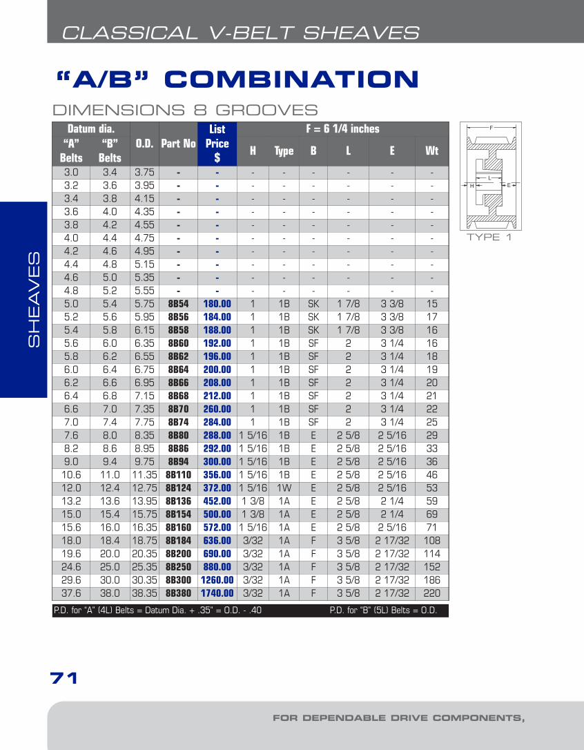
SH
EAVES
FOR DEPENDABLE DRIVE COMPONENTS, BE SURE TO SPECIFY
“A/B” COMBINATION
71
CLASSICAL V-BELT SHEAVES
DIMENSIONS 8 GROOVESDatum dia.
O.D. Part NoList
Price$
F = 6 1/4 inches“A”
Belts“B”
BeltsH Type B L E Wt
3.0 3.4 3.75 - - - - - - - -3.2 3.6 3.95 - - - - - - - -3.4 3.8 4.15 - - - - - - - -3.6 4.0 4.35 - - - - - - - -3.8 4.2 4.55 - - - - - - - -4.0 4.4 4.75 - - - - - - - -4.2 4.6 4.95 - - - - - - - -4.4 4.8 5.15 - - - - - - - -4.6 5.0 5.35 - - - - - - - -4.8 5.2 5.55 - - - - - - - -5.0 5.4 5.75 8B54 180.00 1 1B SK 1 7/8 3 3/8 155.2 5.6 5.95 8B56 184.00 1 1B SK 1 7/8 3 3/8 175.4 5.8 6.15 8B58 188.00 1 1B SK 1 7/8 3 3/8 165.6 6.0 6.35 8B60 192.00 1 1B SF 2 3 1/4 165.8 6.2 6.55 8B62 196.00 1 1B SF 2 3 1/4 186.0 6.4 6.75 8B64 200.00 1 1B SF 2 3 1/4 196.2 6.6 6.95 8B66 208.00 1 1B SF 2 3 1/4 206.4 6.8 7.15 8B68 212.00 1 1B SF 2 3 1/4 216.6 7.0 7.35 8B70 260.00 1 1B SF 2 3 1/4 227.0 7.4 7.75 8B74 284.00 1 1B SF 2 3 1/4 257.6 8.0 8.35 8B80 288.00 1 5/16 1B E 2 5/8 2 5/16 298.2 8.6 8.95 8B86 292.00 1 5/16 1B E 2 5/8 2 5/16 339.0 9.4 9.75 8B94 300.00 1 5/16 1B E 2 5/8 2 5/16 3610.6 11.0 11.35 8B110 356.00 1 5/16 1B E 2 5/8 2 5/16 4612.0 12.4 12.75 8B124 372.00 1 5/16 1W E 2 5/8 2 5/16 5313.2 13.6 13.95 8B136 452.00 1 3/8 1A E 2 5/8 2 1/4 5915.0 15.4 15.75 8B154 500.00 1 3/8 1A E 2 5/8 2 1/4 6915.6 16.0 16.35 8B160 572.00 1 5/16 1A E 2 5/8 2 5/16 7118.0 18.4 18.75 8B184 636.00 3/32 1A F 3 5/8 2 17/32 10819.6 20.0 20.35 8B200 690.00 3/32 1A F 3 5/8 2 17/32 11424.6 25.0 25.35 8B250 880.00 3/32 1A F 3 5/8 2 17/32 15229.6 30.0 30.35 8B300 1260.00 3/32 1A F 3 5/8 2 17/32 18637.6 38.0 38.35 8B380 1740.00 3/32 1A F 3 5/8 2 17/32 220
P.D. for “A” (4L) Belts = Datum Dia. + .35” = O.D. - .40 P.D. for “B” (5L) Belts = O.D.
TYPE 1
4-Class-narrow1.6.qxp 2009-03-19 14:07 Page 10
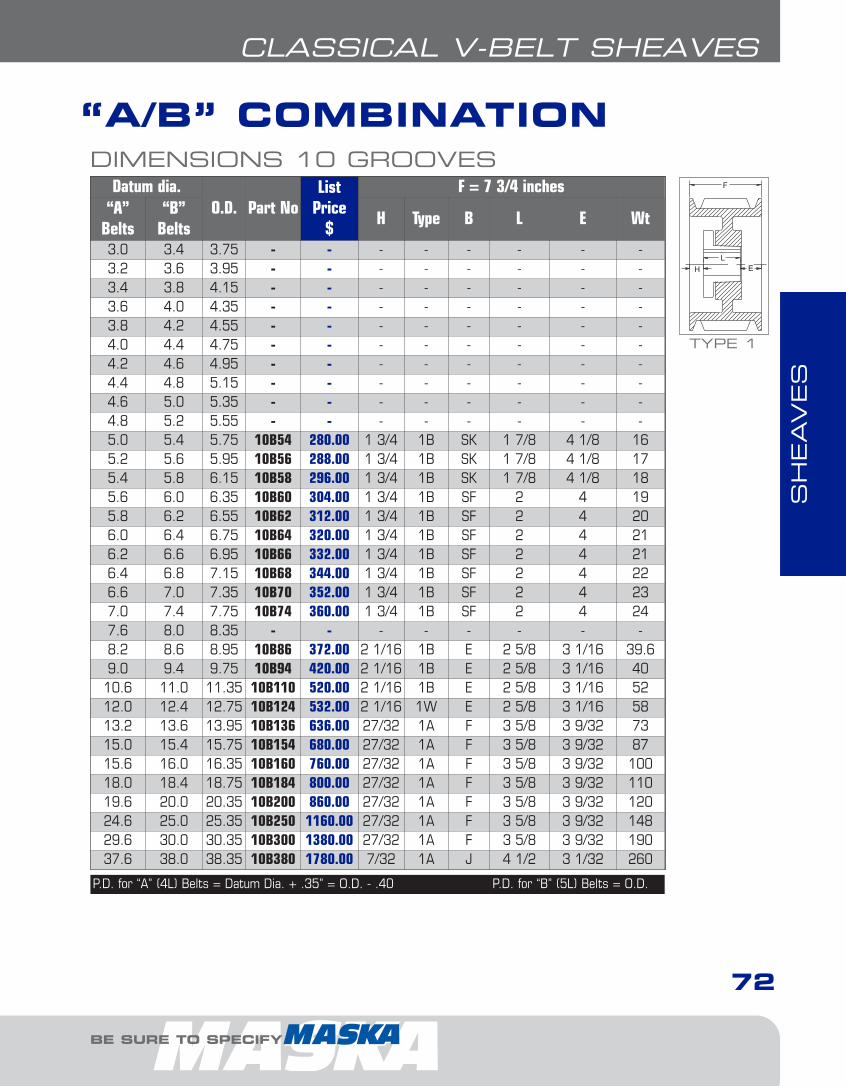
SH
EAVES
BE SURE TO SPECIFY
“A/B” COMBINATION
72
CLASSICAL V-BELT SHEAVES
DIMENSIONS 10 GROOVESDatum dia.
O.D. Part NoList
Price$
F = 7 3/4 inches“A”
Belts“B”
BeltsH Type B L E Wt
3.0 3.4 3.75 - - - - - - - -3.2 3.6 3.95 - - - - - - - -3.4 3.8 4.15 - - - - - - - -3.6 4.0 4.35 - - - - - - - -3.8 4.2 4.55 - - - - - - - -4.0 4.4 4.75 - - - - - - - -4.2 4.6 4.95 - - - - - - - -4.4 4.8 5.15 - - - - - - - -4.6 5.0 5.35 - - - - - - - -4.8 5.2 5.55 - - - - - - - -5.0 5.4 5.75 10B54 280.00 1 3/4 1B SK 1 7/8 4 1/8 165.2 5.6 5.95 10B56 288.00 1 3/4 1B SK 1 7/8 4 1/8 175.4 5.8 6.15 10B58 296.00 1 3/4 1B SK 1 7/8 4 1/8 185.6 6.0 6.35 10B60 304.00 1 3/4 1B SF 2 4 195.8 6.2 6.55 10B62 312.00 1 3/4 1B SF 2 4 206.0 6.4 6.75 10B64 320.00 1 3/4 1B SF 2 4 216.2 6.6 6.95 10B66 332.00 1 3/4 1B SF 2 4 216.4 6.8 7.15 10B68 344.00 1 3/4 1B SF 2 4 226.6 7.0 7.35 10B70 352.00 1 3/4 1B SF 2 4 237.0 7.4 7.75 10B74 360.00 1 3/4 1B SF 2 4 247.6 8.0 8.35 - - - - - - - -8.2 8.6 8.95 10B86 372.00 2 1/16 1B E 2 5/8 3 1/16 39.69.0 9.4 9.75 10B94 420.00 2 1/16 1B E 2 5/8 3 1/16 4010.6 11.0 11.35 10B110 520.00 2 1/16 1B E 2 5/8 3 1/16 5212.0 12.4 12.75 10B124 532.00 2 1/16 1W E 2 5/8 3 1/16 5813.2 13.6 13.95 10B136 636.00 27/32 1A F 3 5/8 3 9/32 7315.0 15.4 15.75 10B154 680.00 27/32 1A F 3 5/8 3 9/32 8715.6 16.0 16.35 10B160 760.00 27/32 1A F 3 5/8 3 9/32 10018.0 18.4 18.75 10B184 800.00 27/32 1A F 3 5/8 3 9/32 11019.6 20.0 20.35 10B200 860.00 27/32 1A F 3 5/8 3 9/32 12024.6 25.0 25.35 10B250 1160.00 27/32 1A F 3 5/8 3 9/32 14829.6 30.0 30.35 10B300 1380.00 27/32 1A F 3 5/8 3 9/32 19037.6 38.0 38.35 10B380 1780.00 7/32 1A J 4 1/2 3 1/32 260
P.D. for “A” (4L) Belts = Datum Dia. + .35” = O.D. - .40 P.D. for “B” (5L) Belts = O.D.
TYPE 1
4-Class-narrow1.6.qxp 2009-03-19 14:07 Page 11

SH
EAVES
FOR DEPENDABLE DRIVE COMPONENTS, BE SURE TO SPECIFY
“C” SECTION
73
CLASSICAL V-BELT SHEAVES
DIMENSIONS 1 GROOVE
Datumdia.
O.D. Part NoList
Price $
F = 1 3/8 inches
H Type B L E Wt
5.0 5.4 - - - - - - - -6.0 6.4 - - - - - - - -7.0 7.4 1C70 112.00 9/16 5B SF 2 1/16 107.5 7.9 1C75 120.00 9/16 5B SF 2 1/16 118.0 8.4 1C80 124.00 9/16 5B SF 2 1/16 13.28.5 8.9 1C85 128.00 9/16 5B SF 2 1/16 15.69.0 9.4 1C90 132.00 19/32 5W SF 2 1/32 139.5 9.9 1C95 136.00 19/32 5W SF 2 1/32 1810.0 10.4 1C100 140.00 11/16 6W SF 2 1/16 1410.5 10.9 1C105 152.00 11/16 6W SF 2 1/16 2011.0 11.4 1C110 172.00 17/32 5W SF 2 3/32 1512.0 12.4 1C120 184.00 11/16 6W SF 2 1/16 1613.0 13.4 1C130 240.00 11/16 6A SF 2 1/16 1814.0 14.4 1C140 260.00 11/16 6A SF 2 1/16 2016.0 16.4 1C160 280.00 11/16 6A SF 2 1/16 2418.0 18.4 1C180 300.00 11/16 6A SF 2 1/16 3220.0 20.4 1C200 320.00 11/16 6A SF 2 1/16 3524.0 24.4 1C240 360.00 11/16 6A SF 2 1/16 46.927.0 27.4 - - - - - - - -30.0 30.4 - - - - - - - -36.0 36.4 - - - - - - - -44.0 44.4 - - - - - - - -50.0 50.4 - - - - - - - -
P.D. for “C” Belts =O.D.
TYPE 5
TYPE 6
4-Class-narrow1.6.qxp 2009-03-19 14:07 Page 12

SH
EAVES
BE SURE TO SPECIFY
“C” SECTION
74
CLASSICAL V-BELT SHEAVES
DIMENSIONS 2 GROOVES
Datumdia.
O.D. Part NoList
Price $
F = 2 3/8 inches
H Type B L E Wt
5.0 5.4 - - - - - - - -6.0 6.4 2C60 126.00 1/16 1B SF 2 5/16 117.0 7.4 2C70 132.00 0 1B SF 2 3/8 137.5 7.9 2C75 136.00 0 1B SF 2 3/8 158.0 8.4 2C80 144.00 0 1B SF 2 3/8 178.5 8.9 2C85 148.00 0 1B SF 2 3/8 199.0 9.4 2C90 152.00 0 1W SF 2 3/8 219.5 9.9 2C95 160.00 0 1W SF 2 3/8 2210.0 10.4 2C100 176.00 0 1W SF 2 3/8 21.810.5 10.9 2C105 188.00 0 1W SF 2 3/8 2311.0 11.4 2C110 200.00 0 1W SF 2 3/8 2612.0 12.4 2C120 210.00 1/4 6W SF 2 5/8 3713.0 13.4 2C130 250.00 1/4 6A SF 2 5/8 3514.0 14.4 2C140 270.00 1/4 6A SF 2 5/8 4016.0 16.4 2C160 290.00 1/4 6A SF 2 5/8 4018.0 18.4 2C180 310.00 1/4 6A SF 2 5/8 5020.0 20.4 2C200 340.00 1/4 6A SF 2 5/8 5524.0 24.4 2C240 460.00 1/4 6A SF 2 5/8 73.127.0 27.4 2C270 550.00 29/32 5A F 3 5/8 11/32 9430.0 30.4 2C300 620.00 29/32 5A F 3 5/8 11/32 10436.0 36.4 - - - - - - - -44.0 44.4 - - - - - - - -50.0 50.4 - - - - - - - -
P.D. for “C” Belts = O.D.
TYPE 1
TYPE 6
TYPE 5
4-Class-narrow1.6.qxp 2009-03-19 14:07 Page 13

SH
EAVES
FOR DEPENDABLE DRIVE COMPONENTS, BE SURE TO SPECIFY
“C” SECTION
75
CLASSICAL V-BELT SHEAVES
DIMENSIONS 3 GROOVES
Datumdia.
O.D. Part NoList
Price $
F = 3 3/8 inches
H Type B L E Wt
5.0 5.4 3C50* 136.00 5/16 1B SD 1 13/16 1 1/4 95.0 5.4 3C50SK1 136.00 13/16 11B SK 1 7/8 2 5/16 10.55.6 6.0 3C56 138.00 5/8 1B SD 1 13/16 15/16 106.0 6.4 3C60 140.00 1/16 1B SF 2 1 5/16 11.37.0 7.4 3C70 144.00 1/2 1B SF 2 7/8 167.5 7.9 3C75 148.00 1/2 1B SF 2 7/8 188.0 8.4 3C80 156.00 11/16 1B E 2 5/8 1/16 218.5 8.9 3C85 176.00 11/16 1B E 2 5/8 1/16 249.0 9.4 3C90 188.00 11/16 1B E 2 5/8 1/16 269.5 9.9 3C95 200.00 11/16 1W E 2 5/8 1/16 29.810.0 10.4 3C100 220.00 11/16 1W E 2 5/8 1/16 3410.5 10.9 3C105 230.00 11/16 1W E 2 5/8 1/16 3711.0 11.4 3C110 240.00 11/16 1W E 2 5/8 1/16 3912.0 12.4 3C120 250.00 11/16 1W E 2 5/8 1/16 43.413.0 13.4 3C130 290.00 11/16 1A E 2 5/8 1/16 4514.0 14.4 3C140 320.00 11/16 1A E 2 5/8 1/16 5016.0 16.4 3C160 330.00 11/16 1A E 2 5/8 1/16 6018.0 18.4 3C180 350.00 11/16 1A E 2 5/8 1/16 6320.0 20.4 3C200 400.00 1/16 6A E 2 5/8 13/16 8124.0 24.4 3C240 480.00 1/16 6A E 2 5/8 13/16 94.727.0 27.4 3C270 580.00 13/32 6A F 3 5/8 5/32 11630.0 30.4 3C300 640.00 13/32 6A F 3 5/8 5/32 134.436.0 36.4 3C360 980.00 13/32 6A F 3 5/8 5/32 15944.0 44.4 3C440 1720.00 13/32 6A F 3 5/8 5/32 19050.0 50.4 3C500 1920.00 13/32 6A F 3 5/8 5/32 250
P.D. for “C” Belts = O.D.1 Reverse mount only.* Mounting bolts are supplied by Maska with this sheave.
TYPE 1
TYPE 6
TYPE 11
4-Class-narrow1.6.qxp 2009-03-19 14:07 Page 14

SH
EAVES
BE SURE TO SPECIFY
“C” SECTION
76
CLASSICAL V-BELT SHEAVES
DIMENSIONS 4 GROOVES
Datumdia.
O.D. Part NoList
Price $
F = 4 3/8 inches
H Type B L E Wt
5.0 5.4 4C50* 156.00 5/8 1B SD 1 13/16 1 15/16 10.25.0 5.4 4C50SK1 156.00 13/16 11B SK 1 7/8 3 5/16 12.05.6 6.0 4C56 158.00 7/8 1B SD 1 13/16 1 11/16 13.06.0 6.4 4C60 160.00 1/16 1B SF 2 2 5/16 15.07.0 7.4 4C70 164.00 3/4 1B SF 2 1 5/8 19.07.5 7.9 4C75 172.00 3/4 1B SF 2 1 5/8 22.08.0 8.4 4C80 196.00 15/16 1B E 2 5/8 13/16 24.08.5 8.9 4C85 208.00 15/16 1B E 2 5/8 13/16 28.09.0 9.4 4C90 224.00 15/16 1B E 2 5/8 13/16 31.09.5 9.9 4C95 228.00 15/16 1B E 2 5/8 13/16 34.810.0 10.4 4C100 240.00 15/16 1B E 2 5/8 13/16 40.010.5 10.9 4C105 260.00 15/16 1W E 2 5/8 13/16 43.011.0 11.4 4C110 272.00 15/16 1W E 2 5/8 13/16 44.012.0 12.4 4C120 300.00 15/16 1W E 2 5/8 13/16 50.013.0 13.4 4C130 336.00 15/16 1A E 2 5/8 13/16 52.014.0 14.4 4C140 364.00 15/16 1A E 2 5/8 13/16 57.016.0 16.4 4C160 420.00 15/16 1A E 2 5/8 13/16 67.018.0 18.4 4C180 430.00 15/16 1A E 2 5/8 13/16 72.020.0 20.4 4C200 450.00 7/16 1A E 2 5/8 1 5/16 86.024.0 24.4 4C240 560.00 3/32 1A F 3 5/8 21/32 113.027.0 27.4 4C270 660.00 3/32 1A F 3 5/8 21/32 140.030.0 30.4 4C300 760.00 3/32 1A F 3 5/8 21/32 149.036.0 36.4 4C360 1120.00 5/32 1A F 3 5/8 19/32 185.044.0 44.4 4C440 1800.00 7/32 2A J 4 1/2 11/32 225.050.0 50.4 4C500 2120.00 7/32 2A J 4 1/2 11/32 275.0
TYPE 2
P.D. for “C” Belts = O.D.1 Reverse mount only.* Mounting bolts are supplied by Maska with this sheave.
TYPE 1
TYPE 11
4-Class-narrow1.6.qxp 2009-03-19 14:07 Page 15

SH
EAVES
FOR DEPENDABLE DRIVE COMPONENTS, BE SURE TO SPECIFY
“C” SECTION
77
CLASSICAL V-BELT SHEAVES
DIMENSIONS 5 GROOVESDatum
dia.O.D. Part No
ListPrice $
F = 5 3/8 inches
H Type B L E Wt
5.0 5.4 - - - - - - - -6.0 6.4 5C60SF 172.00 1/16 1B SF 2 3 5/16 167.0 7.4 5C70 176.00 1 1/8 1B SF 2 2 1/4 237.5 7.9 5C75 224.00 1 1/8 1B SF 2 2 1/4 258.0 8.4 5C80 236.00 1 5/16 1B E 2 5/8 1 7/16 288.5 8.9 5C85 252.00 1 5/16 1B E 2 5/8 1 7/16 329.0 9.4 5C90 256.00 1 5/16 1B E 2 5/8 1 7/16 369.5 9.9 5C95 262.00 1 5/16 1B E 2 5/8 1 7/16 4010.0 10.4 5C100 276.00 1 5/16 1W E 2 5/8 1 7/16 4110.5 10.9 5C105 296.00 1 5/16 1W E 2 5/8 1 7/16 4411.0 11.4 5C110 332.00 1 5/16 1W E 2 5/8 1 7/16 4712.0 12.4 5C120 336.00 1 5/16 1W E 2 5/8 1 7/16 5513.0 13.4 5C130 376.00 1 5/16 1A E 2 5/8 1 7/16 5514.0 14.4 5C140 380.00 1 5/16 1A E 2 5/8 1 7/16 6216.0 16.4 5C160 430.00 1 5/16 1A E 2 5/8 1 7/16 7318.0 18.4 5C180 480.00 1 5/16 1A E 2 5/8 1 7/16 8320.0 20.4 5C200 600.00 3/32 1A F 3 5/8 1 21/32 10924.0 24.4 5C240 640.00 3/32 1A F 3 5/8 1 21/32 12927.0 27.4 5C270 760.00 3/32 1A F 3 5/8 1 21/32 14930.0 30.4 5C300 840.00 3/32 1A F 3 5/8 1 21/32 17236.0 36.4 5C360 1180.00 7/32 1A J 4 1/2 21/32 20544.0 44.4 5C440 1940.00 7/32 1A J 4 1/2 21/32 28550.0 50.4 5C500 2280.00 7/32 1A J 4 1/2 21/32 325
P.D. for “C” Belts = O.D.
TYPE 1
4-Class-narrow1.6.qxp 2009-03-19 14:07 Page 16

SH
EAVES
BE SURE TO SPECIFY
“C” SECTION
78
CLASSICAL V-BELT SHEAVES
DIMENSIONS 6 GROOVESDatum
dia.O.D. Part No
ListPrice $
F = 6 3/8 inches
H Type B L E Wt
5.0 5.4 - - - - - - - -6.0 6.4 6C60 244.00 1 1/16 1B SF 2 3 5/16 247.0 7.4 6C70 248.00 1 1/8 1B SF 2 3 1/4 267.5 7.9 6C75 264.00 1 1/8 1B SF 2 3 1/4 298.0 8.4 6C80 280.00 1 5/16 1B E 2 5/8 2 7/16 318.5 8.9 6C85 288.00 1 5/16 1B E 2 5/8 2 7/16 359.0 9.4 6C90 296.00 1 7/32 1B F 3 5/8 1 17/32 449.5 9.9 6C95 316.00 1 7/32 1B F 3 5/8 1 17/32 4910.0 10.4 6C100 328.00 1 7/32 1B F 3 5/8 1 17/32 5610.5 10.9 6C105 336.00 1 7/32 1B F 3 5/8 1 17/32 5611.0 11.4 6C110 356.00 1 7/32 1W F 3 5/8 1 17/32 5912.0 12.4 6C120 400.00 1 7/32 1W F 3 5/8 1 17/32 6613.0 13.4 6C130 444.00 1 7/32 1A F 3 5/8 1 17/32 6614.0 14.4 6C140 480.00 1 7/32 1A F 3 5/8 1 17/32 7516.0 16.4 6C160 520.00 1 7/32 1A F 3 5/8 1 17/32 8618.0 18.4 6C180 560.00 1 7/32 1A F 3 5/8 1 17/32 10020.0 20.4 6C200 620.00 23/32 1A F 3 5/8 2 1/32 11924.0 24.4 6C240 720.00 23/32 1A F 3 5/8 2 1/32 14127.0 27.4 6C270 880.00 5/32 1A J 4 1/2 1 23/32 17330.0 30.4 6C300 1040.00 5/32 1A J 4 1/2 1 23/32 18936.0 36.4 6C360 1300.00 7/32 1A J 4 1/2 1 21/32 24044.0 44.4 6C440 2040.00 7/32 1A J 4 1/2 1 21/32 29050.0 50.4 6C500 2680.00 11/32 2A M° 6 3/4 23/32 430
P.D. for “C” Belts same = O.D.°Note: M-N-P-W bushings are standard mounting only with these parts. See page 11 for installationinstructions.
TYPE 2
TYPE 1
4-Class-narrow1.6.qxp 2009-03-19 14:07 Page 17

SH
EAVES
FOR DEPENDABLE DRIVE COMPONENTS, BE SURE TO SPECIFY
“C” SECTION
79
CLASSICAL V-BELT SHEAVES
DIMENSIONS 8 GROOVESDatum
dia.O.D. Part No
ListPrice $
F = 8 3/8 inches
H Type B L E Wt
5.0 5.4 - - - - - - - -6.0 6.4 - - - - - - - -7.0 7.4 8C70 320.00 2 13/32 1B SF 2 3 31/32 347.5 7.9 - - - - - - - -8.0 8.4 8C80 390.00 2 3/16 1B E 2 5/8 3 9/16 38.78.5 8.9 8C85 400.00 2 3/16 1B E 2 5/8 3 9/16 449.0 9.4 8C90 410.00 2 3/32 1B F 3 5/8 2 21/32 52.79.5 9.9 8C95 420.00 2 3/32 1B F 3 5/8 2 21/32 5610.0 10.4 8C100 430.00 2 3/32 1B F 3 5/8 2 21/32 6210.5 10.9 8C105 450.00 2 3/32 1B F 3 5/8 2 21/32 7211.0 11.4 8C110 480.00 2 3/32 1B F 3 5/8 2 21/32 8012.0 12.4 8C120 520.00 2 3/32 1B F 3 5/8 2 21/32 9413.0 13.4 8C130 560.00 2 3/32 1W F 3 5/8 2 21/32 9714.0 14.4 8C140 650.00 2 3/32 1A F 3 5/8 2 21/32 9616.0 16.4 8C160 740.00 2 3/32 1A F 3 5/8 2 21/32 11118.0 18.4 8C180 860.00 2 3/32 1A F 3 5/8 2 21/32 12920.0 20.4 8C200 870.00 5/32 1A J 4 1/2 3 23/32 15824.0 24.4 8C240 1020.00 5/32 1A J 4 1/2 3 23/32 17327.0 27.4 8C270 1120.00 5/32 1A J 4 1/2 3 23/32 22630.0 30.4 8C300 1280.00 5/32 1A J 4 1/2 3 23/32 27236.0 36.4 8C360 1600.00 9/32 1A M° 6 3/4 1 11/32 37044.0 44.4 8C440 2560.00 9/32 1A M° 6 3/4 1 11/32 47950.0 50.4 8C500 3000.00 9/32 1A M° 6 3/4 1 11/32 570
P.D. for “C” Belts = O.D.°Note: M-N-P-W bushings are standard mounting only with these parts. See page 11 for installationinstructions.
TYPE 1
4-Class-narrow1.6.qxp 2009-03-19 14:07 Page 18

SH
EAVES
BE SURE TO SPECIFY
“C” SECTION
80
CLASSICAL V-BELT SHEAVES
DIMENSIONS 10 GROOVES
Datumdia.
O.D. Part NoList
Price $
F = 10 3/8 inches
H Type B L E Wt
8.0 8.4 10C80 460.00 2 3/16 1B E 2 5/8 5 9/16 46.38.5 8.9 10C85 480.00 2 3/16 1B E 2 5/8 5 9/16 529.0 9.4 10C90 500.00 2 5/32 1B J 4 1/2 3 23/32 549.5 9.9 10C95 510.00 2 5/32 1B J 4 1/2 3 23/32 67.410.0 10.4 10C100 520.00 2 5/32 1B J 4 1/2 3 23/32 7710.5 10.9 10C105 580.00 2 5/32 1B J 4 1/2 3 23/32 85.711.0 11.4 10C110 600.00 2 5/32 1B J 4 1/2 3 23/32 93.512.0 12.4 10C120 760.00 2 5/32 1B J 4 1/2 3 23/32 111.813.0 13.4 10C130 840.00 2 5/32 1W J 4 1/2 3 23/32 10514.0 14.4 10C140 900.00 2 5/32 1W J 4 1/2 3 23/32 11416.0 16.4 10C160 960.00 2 5/32 1A J 4 1/2 3 23/32 14018.0 18.4 10C180 1080.00 2 5/32 1A J 4 1/2 3 23/32 16020.0 20.4 10C200 1120.00 2 5/32 1A J 4 1/2 3 23/32 16524.0 24.4 10C240 1360.00 9/32 1A M° 6 3/4 3 11/32 22530.0 30.4 10C300 1760.00 9/32 1A M° 6 3/4 3 11/32 27536.0 36.4 10C360 2560.00 9/32 1A M° 6 3/4 3 11/32 34044.0 44.4 10C440 2800.00 9/32 1A M° 6 3/4 3 11/32 46050.0 50.4 10C500 3500.00 9/32 1A M° 6 3/4 3 11/32 550
DIMENSIONS 12 GROOVES
Datumdia.
O.D. Part NoList
Price $
F = 12 3/8 inches
H Type B L E Wt
9.0 9.4 12C90 700.00 2 21/32 1B J 4 1/2 5 7/32 689.5 9.9 12C95 720.00 2 21/32 1B J 4 1/2 5 7/32 7510.0 10.4 12C100 740.00 2 21/32 1B J 4 1/2 5 7/32 8610.5 10.9 12C105 760.00 2 21/32 1B J 4 1/2 5 7/32 9611.0 11.4 12C110 780.00 2 21/32 1B J 4 1/2 5 7/32 10412.0 12.4 12C120 800.00 2 21/32 1B J 4 1/2 5 7/32 118.713.0 13.4 12C130 920.00 2 21/32 1W J 4 1/2 5 7/32 13814.0 14.4 12C140 1180.00 2 21/32 1W J 4 1/2 5 7/32 15316.0 16.4 12C160 1360.00 2 21/32 1A J 4 1/2 5 7/32 17518.0 18.4 12C180 1400.00 2 21/32 1A J 4 1/2 5 7/32 19820.0 20.4 12C200 1480.00 9/32 1A M° 6 3/4 5 11/32 23724.0 24.4 12C240 1520.00 9/32 1A M° 6 3/4 5 11/32 27730.0 30.4 12C300 1780.00 9/32 1A M° 6 3/4 5 11/32 35736.0 36.4 12C360 2640.00 9/32 1A M° 6 3/4 5 11/32 43044.0 44.4 12C440 3200.00 9/32 1A M° 6 3/4 5 11/32 52050.0 50.4 12C500 3900.00 9/32 1A M° 6 3/4 5 11/32 595
TYPE 1
P.D. for “C” Belts = O.D.°Note: M-N-P-W bushings are standard mounting only with these parts. See page 11 for installationinstructions.
4-Class-narrow1.6.qxp 2009-03-19 14:07 Page 19

SH
EAVES
FOR DEPENDABLE DRIVE COMPONENTS, BE SURE TO SPECIFY
“D” SECTION
81
CLASSICAL V-BELT SHEAVES
DIMENSIONS 3 GROOVES
Datumdia.
O.D. Part NoList
Price $
F = 4 5/8 inches
H Type B L E Wt
12.0 12.6 3D120 560.00 9/32 1W F 3 5/8 23/32 6413.0 13.6 3D130 600.00 9/32 1W F 3 5/8 23/32 7213.5 14.1 3D135 620.00 9/32 1W F 3 5/8 23/32 7614.0 14.6 3D140 640.00 9/32 1W F 3 5/8 23/32 7914.5 15.1 3D145 680.00 9/32 1W F 3 5/8 23/32 8415.0 15.6 3D150 720.00 9/32 1W F 3 5/8 23/32 8915.5 16.1 3D155 740.00 9/32 1W F 3 5/8 23/32 9416.0 16.6 3D160 760.00 9/32 1A F 3 5/8 23/32 9517.0 17.6 - - - - - - - -18.0 18.6 3D180 800.00 7/32 6A J 4 1/2 11/32 11520.0 20.6 - - - - - - - -22.0 22.6 3D220 960.00 7/32 6A J 4 1/2 11/32 13527.0 27.6 3D270 1160.00 7/32 6A J 4 1/2 11/32 17033.0 33.6 3D330 1640.00 7/32 6A J 4 1/2 11/32 21540.0 40.6 3D400 2040.00 7/32 6A J 4 1/2 11/32 275
DIMENSIONS 4 GROOVES
Datumdia.
O.D. Part NoList
Price $
F = 6 1/16 inches
H Type B L E Wt
12.0 12.6 4D120 600.00 1 3/32 1W F 3 5/8 1 11/32 7713.0 13.6 4D130 640.00 1 3/32 1W F 3 5/8 1 11/32 8513.5 14.1 4D135 660.00 1 3/32 1W F 3 5/8 1 11/32 9014.0 14.6 4D140 680.00 1 3/32 1W F 3 5/8 1 11/32 9514.5 15.1 4D145 780.00 1 3/32 1W F 3 5/8 1 11/32 10015.0 15.6 4D150 800.00 1 3/32 1W F 3 5/8 1 11/32 10715.5 16.1 4D155 820.00 1 3/32 1W F 3 5/8 1 11/32 11216.0 16.6 4D160 840.00 1 3/32 1A F 3 5/8 1 11/32 11017.0 17.6 4D170 940.00 1 5/32 1A J 4 1/2 13/32 12718.0 18.6 4D180 960.00 1 5/32 1A J 4 1/2 13/32 13120.0 20.6 4D200 980.00 1 5/32 1A J 4 1/2 13/32 14522.0 22.6 4D220 1000.00 5/32 1A J 4 1/2 1 13/32 16027.0 27.6 4D270 1280.00 5/32 1A J 4 1/2 1 13/32 20033.0 33.6 4D330 2120.00 9/32 2A Mº 6 3/4 31/32 28540.0 40.6 4D400 2240.00 9/32 2A Mº 6 3/4 31/32 375
TYPE 6
TYPE 2
TYPE 1
P.D. for “D” Belts = O.D.°Note: M-N-P-W bushings are standard mounting only with these parts. See page 11 for installationinstructions.
4-Class-narrow1.6.qxp 2009-03-19 14:07 Page 20

SH
EAVES
BE SURE TO SPECIFY
“D” SECTION
82
CLASSICAL V-BELT SHEAVES
DIMENSIONS 5 GROOVES
Datumdia.
O.D. Part NoList
Price $
F = 7 1/2 inches
H Type B L E Wt
12.0 12.6 5D120 780.00 1 27/32 1W F 3 5/8 2 1/32 8913.0 13.6 5D130 800.00 1 27/32 1W F 3 5/8 2 1/32 10013.5 14.1 5D135 820.00 1 27/32 1W F 3 5/8 2 1/32 10514.0 14.6 5D140 860.00 1 27/32 1W F 3 5/8 2 1/32 11114.5 15.1 5D145 920.00 1 27/32 1W F 3 5/8 2 1/32 11815.0 15.6 5D150 940.00 1 27/32 1W F 3 5/8 2 1/32 12515.5 16.1 5D155 960.00 1 27/32 1W F 3 5/8 2 1/32 13116.0 16.6 5D160 980.00 1 27/32 1A F 3 5/8 2 1/32 11017.0 17.6 5D170 1000.00 1 29/32 1A J 4 1/2 1 3/32 14818.0 18.6 5D180 1020.00 1 29/32 1A J 4 1/2 1 3/32 13120.0 20.6 5D200 1220.00 5/32 1A J 4 1/2 2 27/32 14822.0 22.6 5D220 1420.00 5/32 1A J 4 1/2 2 27/32 15227.0 27.6 5D270 1740.00 9/32 1A Mº 6 3/4 15/32 25033.0 33.6 5D330 2180.00 9/32 1A Mº 6 3/4 15/32 32140.0 40.6 5D400 2700.00 9/32 1A Mº 6 3/4 15/32 42448.0 48.6 5D480 3080.00 9/32 1A Mº 6 3/4 15/32 55058.0 58.6 5D580 4280.00 9/32 1A Mº 6 3/4 15/32 600
DIMENSIONS 6 GROOVES
Datumdia.
O.D. Part NoList
Price $
F = 8 15/16 inches
H Type B L E Wt
12.0 12.6 6D120 960.00 1 29/32 1B J 4 1/2 2 17/32 11613.0 13.6 6D130 980.00 1 29/32 1B J 4 1/2 2 17/32 13713.5 14.1 6D135 1000.00 1 29/32 1B J 4 1/2 2 17/32 14714.0 14.6 6D140 1020.00 1 29/32 1B J 4 1/2 2 17/32 15814.5 15.1 6D145 1040.00 1 29/32 1B J 4 1/2 2 17/32 17015.0 15.6 6D150 1060.00 1 29/32 1W J 4 1/2 2 17/32 14715.5 16.1 6D155 1080.00 1 29/32 1W J 4 1/2 2 17/32 15316.0 16.6 6D160 1100.00 1 29/32 1A J 4 1/2 2 17/32 13717.0 17.6 6D170 1120.00 1 29/32 1A J 4 1/2 2 17/32 17518.0 18.6 6D180 1140.00 1 29/32 1A J 4 1/2 2 17/32 15920.0 20.6 6D200 1480.00 1 29/32 1A J 4 1/2 2 17/32 18522.0 22.6 6D220 1840.00 9/32 1A Mº 6 3/4 1 29/32 22527.0 27.6 6D270 1900.00 9/32 1A Mº 6 3/4 1 29/32 30033.0 33.6 6D330 2460.00 9/32 1A Mº 6 3/4 1 29/32 35040.0 40.6 6D400 2980.00 9/32 1A Mº 6 3/4 1 29/32 46048.0 48.6 6D480 3480.00 9/32 1A Mº 6 3/4 1 29/32 60058.0 58.6 6D580 4520.00 3/16 1A Nº 8 1/8 5/8 760
TYPE 1
P.D. for “D” Belts = O.D.°Note: M-N-P-W bushings are standard mounting only with these parts. See page 11 for installationinstructions.
4-Class-narrow1.6.qxp 2009-03-19 14:07 Page 21
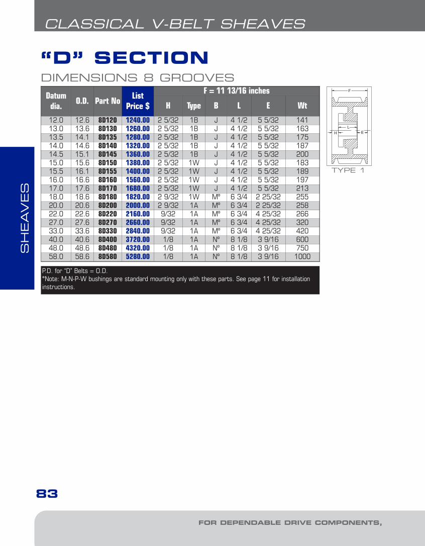
SH
EAVES
FOR DEPENDABLE DRIVE COMPONENTS, BE SURE TO SPECIFY
“D” SECTION
83
CLASSICAL V-BELT SHEAVES
DIMENSIONS 8 GROOVESDatum
dia.O.D. Part No
ListPrice $
F = 11 13/16 inches
H Type B L E Wt
12.0 12.6 8D120 1240.00 2 5/32 1B J 4 1/2 5 5/32 14113.0 13.6 8D130 1260.00 2 5/32 1B J 4 1/2 5 5/32 16313.5 14.1 8D135 1280.00 2 5/32 1B J 4 1/2 5 5/32 17514.0 14.6 8D140 1320.00 2 5/32 1B J 4 1/2 5 5/32 18714.5 15.1 8D145 1360.00 2 5/32 1B J 4 1/2 5 5/32 20015.0 15.6 8D150 1380.00 2 5/32 1W J 4 1/2 5 5/32 18315.5 16.1 8D155 1400.00 2 5/32 1W J 4 1/2 5 5/32 18916.0 16.6 8D160 1560.00 2 5/32 1W J 4 1/2 5 5/32 19717.0 17.6 8D170 1680.00 2 5/32 1W J 4 1/2 5 5/32 21318.0 18.6 8D180 1820.00 2 9/32 1W Mº 6 3/4 2 25/32 25520.0 20.6 8D200 2000.00 2 9/32 1A Mº 6 3/4 2 25/32 25822.0 22.6 8D220 2160.00 9/32 1A Mº 6 3/4 4 25/32 26627.0 27.6 8D270 2660.00 9/32 1A Mº 6 3/4 4 25/32 32033.0 33.6 8D330 2840.00 9/32 1A Mº 6 3/4 4 25/32 42040.0 40.6 8D400 3720.00 1/8 1A Nº 8 1/8 3 9/16 60048.0 48.6 8D480 4320.00 1/8 1A Nº 8 1/8 3 9/16 75058.0 58.6 8D580 5280.00 1/8 1A Nº 8 1/8 3 9/16 1000
TYPE 1
P.D. for “D” Belts = O.D.°Note: M-N-P-W bushings are standard mounting only with these parts. See page 11 for installationinstructions.
4-Class-narrow1.6.qxp 2009-03-19 14:07 Page 22
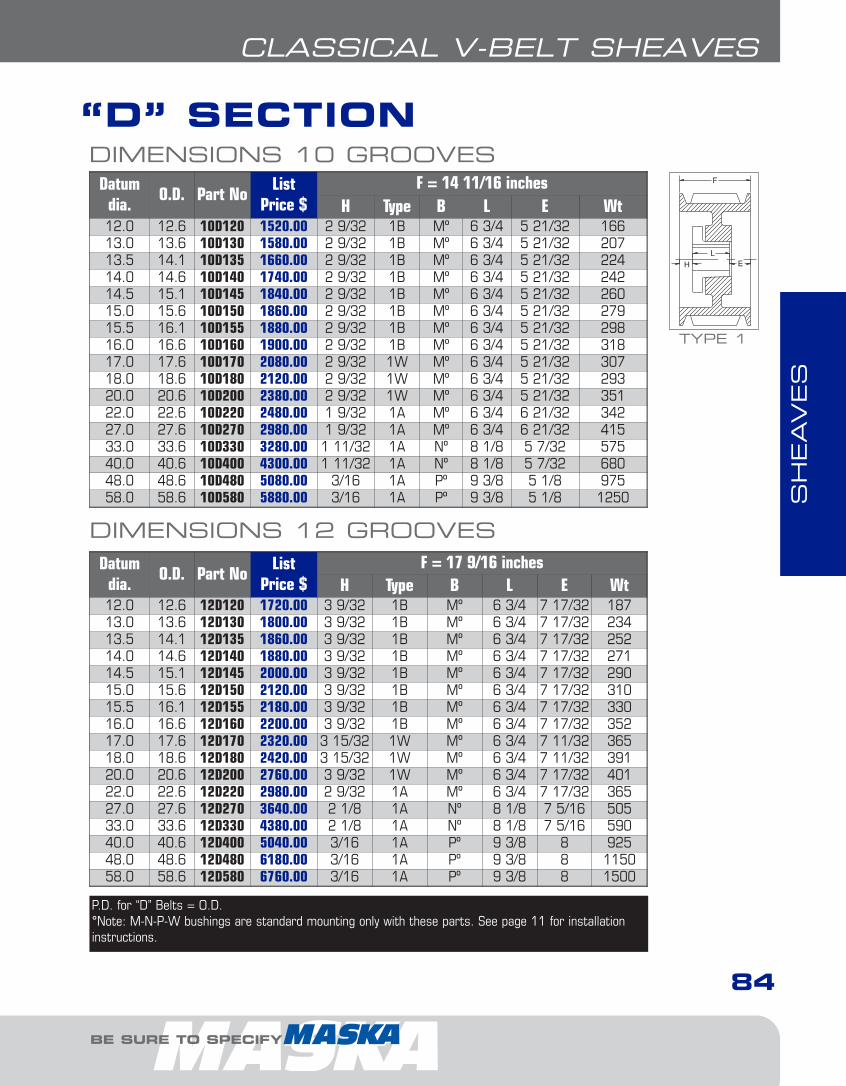
SH
EAVES
BE SURE TO SPECIFY
84
CLASSICAL V-BELT SHEAVES
DIMENSIONS 10 GROOVESDatum
dia.O.D. Part No
ListPrice $
F = 14 11/16 inchesH Type B L E Wt
12.0 12.6 10D120 1520.00 2 9/32 1B Mº 6 3/4 5 21/32 16613.0 13.6 10D130 1580.00 2 9/32 1B Mº 6 3/4 5 21/32 20713.5 14.1 10D135 1660.00 2 9/32 1B Mº 6 3/4 5 21/32 22414.0 14.6 10D140 1740.00 2 9/32 1B Mº 6 3/4 5 21/32 24214.5 15.1 10D145 1840.00 2 9/32 1B Mº 6 3/4 5 21/32 26015.0 15.6 10D150 1860.00 2 9/32 1B Mº 6 3/4 5 21/32 27915.5 16.1 10D155 1880.00 2 9/32 1B Mº 6 3/4 5 21/32 29816.0 16.6 10D160 1900.00 2 9/32 1B Mº 6 3/4 5 21/32 31817.0 17.6 10D170 2080.00 2 9/32 1W Mº 6 3/4 5 21/32 30718.0 18.6 10D180 2120.00 2 9/32 1W Mº 6 3/4 5 21/32 29320.0 20.6 10D200 2380.00 2 9/32 1W Mº 6 3/4 5 21/32 35122.0 22.6 10D220 2480.00 1 9/32 1A Mº 6 3/4 6 21/32 34227.0 27.6 10D270 2980.00 1 9/32 1A Mº 6 3/4 6 21/32 41533.0 33.6 10D330 3280.00 1 11/32 1A Nº 8 1/8 5 7/32 57540.0 40.6 10D400 4300.00 1 11/32 1A Nº 8 1/8 5 7/32 68048.0 48.6 10D480 5080.00 3/16 1A Pº 9 3/8 5 1/8 97558.0 58.6 10D580 5880.00 3/16 1A Pº 9 3/8 5 1/8 1250
DIMENSIONS 12 GROOVESDatum
dia.O.D. Part No
ListPrice $
F = 17 9/16 inchesH Type B L E Wt
12.0 12.6 12D120 1720.00 3 9/32 1B Mº 6 3/4 7 17/32 18713.0 13.6 12D130 1800.00 3 9/32 1B Mº 6 3/4 7 17/32 23413.5 14.1 12D135 1860.00 3 9/32 1B Mº 6 3/4 7 17/32 25214.0 14.6 12D140 1880.00 3 9/32 1B Mº 6 3/4 7 17/32 27114.5 15.1 12D145 2000.00 3 9/32 1B Mº 6 3/4 7 17/32 29015.0 15.6 12D150 2120.00 3 9/32 1B Mº 6 3/4 7 17/32 31015.5 16.1 12D155 2180.00 3 9/32 1B Mº 6 3/4 7 17/32 33016.0 16.6 12D160 2200.00 3 9/32 1B Mº 6 3/4 7 17/32 35217.0 17.6 12D170 2320.00 3 15/32 1W Mº 6 3/4 7 11/32 36518.0 18.6 12D180 2420.00 3 15/32 1W Mº 6 3/4 7 11/32 39120.0 20.6 12D200 2760.00 3 9/32 1W Mº 6 3/4 7 17/32 40122.0 22.6 12D220 2980.00 2 9/32 1A Mº 6 3/4 7 17/32 36527.0 27.6 12D270 3640.00 2 1/8 1A Nº 8 1/8 7 5/16 50533.0 33.6 12D330 4380.00 2 1/8 1A Nº 8 1/8 7 5/16 59040.0 40.6 12D400 5040.00 3/16 1A Pº 9 3/8 8 92548.0 48.6 12D480 6180.00 3/16 1A Pº 9 3/8 8 115058.0 58.6 12D580 6760.00 3/16 1A Pº 9 3/8 8 1500
TYPE 1
P.D. for “D” Belts = O.D.°Note: M-N-P-W bushings are standard mounting only with these parts. See page 11 for installationinstructions.
“D” SECTION
4-Class-narrow1.6.qxp 2009-03-19 14:07 Page 23

SH
EAVES
FOR DEPENDABLE DRIVE COMPONENTS, BE SURE TO SPECIFY
85
NARROW V-BELT SHEAVES
NARROW 3V, 5V & 8V
EXAMPLE: 5-5V11.3
5 5V
5: NUMBER OF GROOVES
5V: SHEAVE SECTION ("5V")
11.3: OUTSIDE DIAMETER (11.3")
HOW TO ORDER
11.3
• Complete line in stock, including larger models• Higher HP than classical model; compact,
light-weight drives• Designed for use with QD bushing • 3V model from 1-6;8;10 grooves, 2.2”-33.5” O.D.• 5V model from 2-6;8;10 grooves, 4.4”-50” O.D.• 8V model from 4-6;8;10;12 grooves, 12.5”- 71” O.D.
DID YOU KNOW THAT...
1 For mounting instructionswith QD bushings, see page11.
2 All Charts: The type ofsheave construction is indi-cated in the column entitled« T ». The number refers tothe drawing and the letter asfollows: A = arms; B = block;W = web.
3 "B" Column indicates thecorresponding bushing sizerequired.
4 All dimensions are to the closest fraction.
•DO NOT use these gray cast iron sheaveswith rim speeds in excess of 6500 feet perminute. Note that the max. RPM indicated
on the arm of the sheave is based on the 6500ft/min. limit, and doesn’t take into consideration theneed for dynamic balancing (two planes). Please referto the chart on page 32 to verify the validity ofdynamic balancing in your application. All operational PT products when used in a drive arepotentially dangerous and must be guarded by theuser as required by applicable laws, regulations,standards and good safety practice. (Refer to ANSIStandard B15.1)
• When ordering a sheave to be dynamically balanced,you must specify the sheave operational speed.Maska recommends ordering the matching bushingwith the sheave to ensure a balancing grade of 6.3.If the bushing is not ordered at the same time, a disclaimer will be sent to the customer dischargingMaska from possible vibration problems related tothe drive.
IMPORTANT REMINDER
4-Class-narrow1.6.qxp 2009-03-19 14:07 Page 24
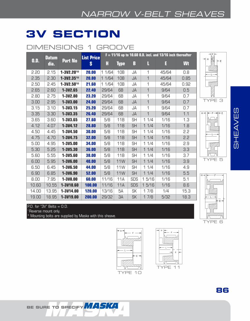
SH
EAVES
BE SURE TO SPECIFY
86
NARROW V-BELT SHEAVES
3V SECTIONDIMENSIONS 1 GROOVE
O.D.Datum
dia.Part No
List Price$
F = 11/16 up to 10.60 O.D. incl. and 13/16 inch thereafter
H Type B L E Wt
2.20 2.15 1-3V2.201* 20.00 1 1/64 10B JA 1 45/64 0.82.35 2.30 1-3V2.351* 20.80 1 1/64 10B JA 1 45/64 0.852.50 2.45 1-3V2.501* 21.60 1 1/64 10B JA 1 45/64 0.922.65 2.60 1-3V2.65 22.40 29/64 6B JA 1 9/64 0.52.80 2.75 1-3V2.80 23.20 29/64 6B JA 1 9/64 0.73.00 2.95 1-3V3.00 24.00 29/64 6B JA 1 9/64 0.73.15 3.10 1-3V3.15 25.20 29/64 6B JA 1 9/64 0.73.35 3.30 1-3V3.35 26.40 29/64 6B JA 1 9/64 1.13.65 3.60 1-3V3.65 27.60 5/8 11B SH 1 1/4 1/16 1.34.12 4.07 1-3V4.12 28.80 5/8 11B SH 1 1/4 1/16 1.84.50 4.45 1-3V4.50 30.00 5/8 11B SH 1 1/4 1/16 2.24.75 4.70 1-3V4.75 32.00 5/8 11B SH 1 1/4 1/16 2.25.00 4.95 1-3V5.00 34.00 5/8 11B SH 1 1/4 1/16 2.95.30 5.25 1-3V5.30 36.00 5/8 11B SH 1 1/4 1/16 3.35.60 5.55 1-3V5.60 38.00 5/8 11B SH 1 1/4 1/16 3.76.00 5.95 1-3V6.00 40.00 5/8 11W SH 1 1/4 1/16 3.96.50 6.45 1-3V6.50 44.00 5/8 11W SH 1 1/4 1/16 4.96.90 6.85 1-3V6.90 52.00 5/8 11W SH 1 1/4 1/16 5.58.00 7.95 1-3V8.00 60.00 11/16 11A SDS 1 5/16 1/16 5.110.60 10.55 1-3V10.60 100.00 11/16 11A SDS 1 5/16 1/16 8.614.00 13.95 1-3V14.00 120.00 13/16 5A SK 1 7/8 1/4 15.319.00 18.95 1-3V19.00 200.00 29/32 3A SK 1 7/8 5/32 18.3
P.D. for “3V” Belts = O.D.1 Reverse mount only.* Mounting bolts are supplied by Maska with this sheave.
TYPE 6
TYPE 11TYPE 10
TYPE 3
TYPE 5
4-Class-narrow1.6.qxp 2009-03-19 14:07 Page 25
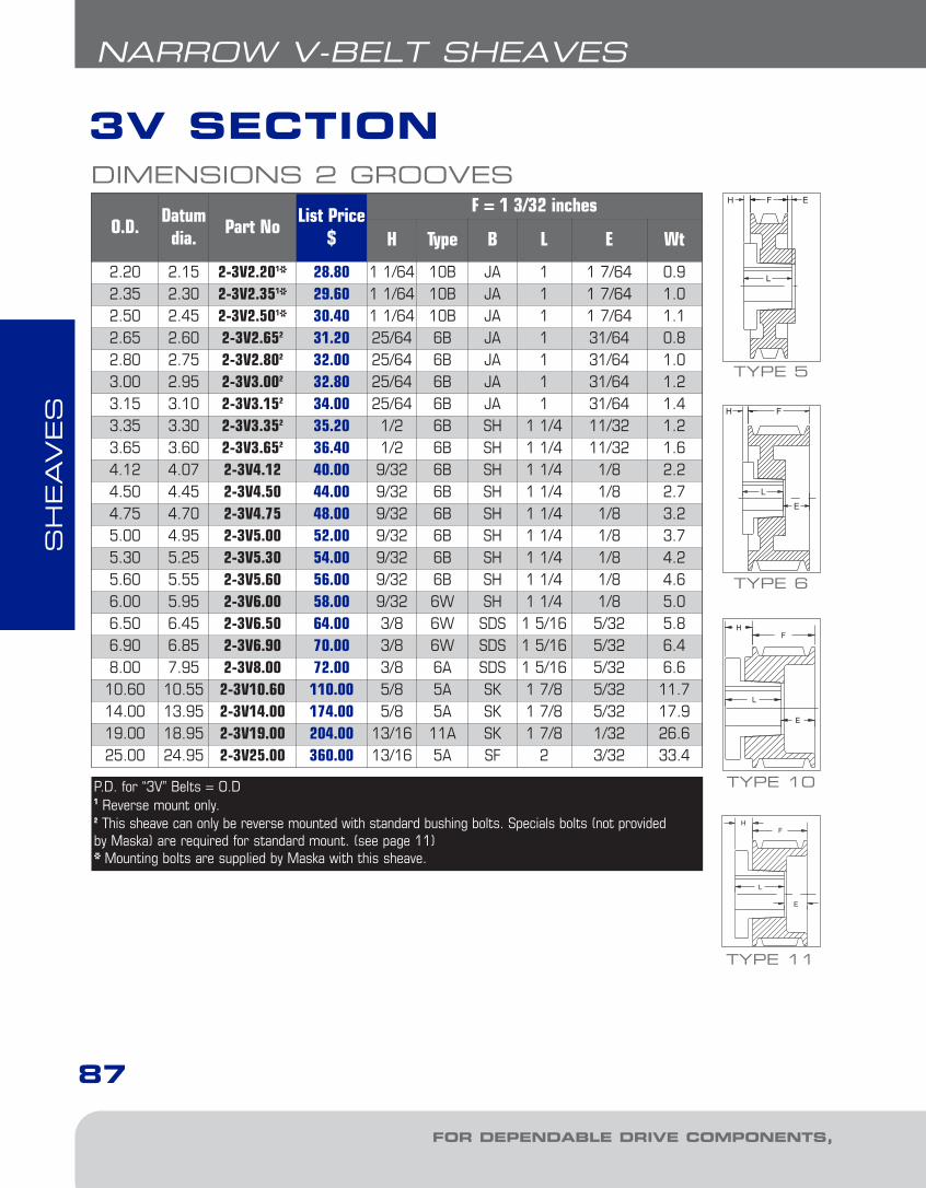
SH
EAVES
FOR DEPENDABLE DRIVE COMPONENTS, BE SURE TO SPECIFY
87
NARROW V-BELT SHEAVES
DIMENSIONS 2 GROOVES
O.D.Datum
dia.Part No
List Price$
F = 1 3/32 inches
H Type B L E Wt
2.20 2.15 2-3V2.201* 28.80 1 1/64 10B JA 1 1 7/64 0.92.35 2.30 2-3V2.351* 29.60 1 1/64 10B JA 1 1 7/64 1.02.50 2.45 2-3V2.501* 30.40 1 1/64 10B JA 1 1 7/64 1.12.65 2.60 2-3V2.652 31.20 25/64 6B JA 1 31/64 0.82.80 2.75 2-3V2.802 32.00 25/64 6B JA 1 31/64 1.03.00 2.95 2-3V3.002 32.80 25/64 6B JA 1 31/64 1.23.15 3.10 2-3V3.152 34.00 25/64 6B JA 1 31/64 1.43.35 3.30 2-3V3.352 35.20 1/2 6B SH 1 1/4 11/32 1.23.65 3.60 2-3V3.652 36.40 1/2 6B SH 1 1/4 11/32 1.64.12 4.07 2-3V4.12 40.00 9/32 6B SH 1 1/4 1/8 2.24.50 4.45 2-3V4.50 44.00 9/32 6B SH 1 1/4 1/8 2.74.75 4.70 2-3V4.75 48.00 9/32 6B SH 1 1/4 1/8 3.25.00 4.95 2-3V5.00 52.00 9/32 6B SH 1 1/4 1/8 3.75.30 5.25 2-3V5.30 54.00 9/32 6B SH 1 1/4 1/8 4.25.60 5.55 2-3V5.60 56.00 9/32 6B SH 1 1/4 1/8 4.66.00 5.95 2-3V6.00 58.00 9/32 6W SH 1 1/4 1/8 5.06.50 6.45 2-3V6.50 64.00 3/8 6W SDS 1 5/16 5/32 5.86.90 6.85 2-3V6.90 70.00 3/8 6W SDS 1 5/16 5/32 6.48.00 7.95 2-3V8.00 72.00 3/8 6A SDS 1 5/16 5/32 6.610.60 10.55 2-3V10.60 110.00 5/8 5A SK 1 7/8 5/32 11.714.00 13.95 2-3V14.00 174.00 5/8 5A SK 1 7/8 5/32 17.919.00 18.95 2-3V19.00 204.00 13/16 11A SK 1 7/8 1/32 26.625.00 24.95 2-3V25.00 360.00 13/16 5A SF 2 3/32 33.4
P.D. for “3V” Belts = O.D1 Reverse mount only.2 This sheave can only be reverse mounted with standard bushing bolts. Specials bolts (not providedby Maska) are required for standard mount. (see page 11)* Mounting bolts are supplied by Maska with this sheave.
3V SECTION
TYPE 6
TYPE 5
TYPE 11
TYPE 10
4-Class-narrow1.6.qxp 2009-03-19 14:07 Page 26

SH
EAVES
BE SURE TO SPECIFY
88
NARROW V-BELT SHEAVES
3V SECTIONDIMENSIONS 3 GROOVES
O.D.Datum
dia.Part No
List Price$
F = 1 1/2 inches
H Type B L E Wt
2.65 2.60 3-3V2.652 36.80 25/64 6B JA 1 57/64 1.12.80 2.75 3-3V2.802 37.60 25/64 6B JA 1 57/64 1.33.00 2.95 +3-3V3.001* 38.80 1 1/32 10B SH 1 1/4 1 9/32 1.63.15 3.10 +3-3V3.151* 40.00 1 10B SH 1 1/4 1 1/4 2.03.35 3.30 3-3V3.352 41.20 9/16 6B SH 1 1/4 13/16 1.83.65 3.60 3-3V3.652 42.40 9/16 6B SH 1 1/4 13/16 2.44.12 4.07 3-3V4.12 44.00 0 4B SH 1 1/4 1/4 2.74.50 4.45 3-3V4.50 50.00 0 4B SDS 1 5/16 3/16 3.04.75 4.70 3-3V4.75 54.00 0 4B SDS 1 5/16 3/16 3.75.00 4.95 3-3V5.00 58.00 0 4B SDS 1 5/16 3/16 4.25.30 5.25 3-3V5.30 60.00 0 4B SDS 1 5/16 3/16 4.75.60 5.55 3-3V5.60 62.00 0 4B SDS 1 5/16 3/16 5.26.00 5.95 3-3V6.00 66.00 0 4B SDS 1 5/16 3/16 6.26.50 6.45 3-3V6.50 68.00 0 4W SDS 1 5/16 3/16 6.76.90 6.85 3-3V6.90 80.00 0 4W SDS 1 5/16 3/16 7.58.00 7.95 3-3V8.00 86.00 5/8 6A SK 1 7/8 1/4 9.810.60 10.55 3-3V10.60 126.00 5/8 6A SK 1 7/8 1/4 14.014.00 13.95 3-3V14.00 184.00 5/8 6A SK 1 7/8 1/4 19.419.00 18.95 3-3V19.00 216.00 13/16 11A SF 2 5/16 32.125.00 24.95 3-3V25.00 400.00 13/16 11A SF 2 5/16 38.533.50 33.45 3-3V33.50 720.00 23/32 6A SF 2 7/32 79.3
P.D. for “3V” Belts = O.D. + For 3-3V3.00: F=1.912” + For 3-3V3.15: F=1 7/8”1 Reverse mount only.2 This sheave can only be reverse mounted with standard bushing bolts. Specials bolts (not providedby Maska) are required for standard mount. (see page 11)* Mounting bolts are supplied by Maska with this sheave.
TYPE 6
TYPE 11
TYPE 10
TYPE 4
4-Class-narrow1.6.qxp 2009-03-19 14:07 Page 27

SH
EAVES
FOR DEPENDABLE DRIVE COMPONENTS, BE SURE TO SPECIFY
3V SECTION
89
NARROW V-BELT SHEAVES
DIMENSIONS 4 GROOVES
O.D.Datum
dia.Part No
List Price$
F = 1 29/32 inches
H Type B L E Wt
2.65 2.60 4-3V2.652 42.40 25/64 6B JA 1 1 19/64 1.42.80 2.75 4-3V2.802 42.80 25/64 6B JA 1 1 19/64 1.63.00 2.95 4-3V3.001* 43.20 1 1/32 10B SH 1 1/4 1 11/16 2.33.15 3.10 4-3V3.151* 44.80 1 10B SH 1 1/4 1 21/32 2.73.35 3.30 4-3V3.352 46.40 1/2 6B SH 1 1/4 1 5/32 2.33.65 3.60 4-3V3.652 48.00 1/2 6B SH 1 1/4 1 5/32 3.14.12 4.07 4-3V4.12 50.00 3/16 1B SH 1 1/4 15/32 3.24.50 4.45 4-3V4.50 52.00 3/16 1B SDS 1 5/16 13/32 3.44.75 4.70 4-3V4.75 56.00 1/8 1B SDS 1 5/16 15/32 4.45.00 4.95 4-3V5.00 60.00 1/8 1B SDS 1 5/16 15/32 5.05.30 5.25 4-3V5.30 64.00 1/8 1B SDS 1 5/16 15/32 6.05.60 5.55 4-3V5.60 66.00 1/8 1B SDS 1 5/16 15/32 6.26.00 5.95 4-3V6.00 70.00 1/4 6B SK 1 7/8 9/32 7.86.50 6.45 4-3V6.50 72.00 1/4 6B SK 1 7/8 9/32 9.56.90 6.85 4-3V6.90 82.00 1/4 6B SK 1 7/8 9/32 11.18.00 7.95 4-3V8.00 88.00 1/4 6A SK 1 7/8 9/32 11.210.60 10.55 4-3V10.60 128.00 1/4 6A SK 1 7/8 9/32 16.014.00 13.95 4-3V14.00 196.00 1/4 6A SK 1 7/8 9/32 25.019.00 18.95 4-3V19.00 252.00 1/16 5A SF 2 1/32 39.825.00 24.95 4-3V25.00 412.00 7/16 6A SF 2 11/32 51.133.50 33.45 4-3V33.50 780.00 25/32 6A E 2 5/8 1/16 94.1
P.D. for “3V” Belts = O.D.1 Reverse mount only.2 This sheave can only be reverse mounted with standard bushing bolts. Specials bolts (not providedby Maska) are required for standard mount. (see page 11)* Mounting bolts are supplied by Maska with this sheave.
TYPE 6
TYPE 5
TYPE 10
TYPE 1
4-Class-narrow1.6.qxp 2009-03-19 14:07 Page 28

SH
EAVES
BE SURE TO SPECIFY
3V SECTION
90
NARROW V-BELT SHEAVES
DIMENSIONS 5 GROOVES
O.D.Datum
dia.Part No
List Price$
F = 2 5/16 inches
H Type B L E Wt
4.75 4.70 5-3V4.75 62.00 1/8 1B SDS 1 5/16 7/8 4.75.00 4.95 5-3V5.00 68.00 1/8 1B SDS 1 5/16 7/8 6.05.30 5.25 5-3V5.30 70.00 1/16 1B SK 1 7/8 3/8 6.25.60 5.55 5-3V5.60 76.00 1/32 1B SK 1 7/8 13/32 7.46.00 5.95 5-3V6.00 78.00 1/16 1B SK 1 7/8 3/8 8.86.50 6.45 5-3V6.50 80.00 1/16 1B SK 1 7/8 3/8 9.96.90 6.85 5-3V6.90 88.00 1/32 1B SK 1 7/8 13/32 11.58.00 7.95 5-3V8.00 94.00 1/16 1W SK 1 7/8 3/8 14.510.60 10.55 5-3V10.60 130.00 5/32 1A SK 1 7/8 9/32 19.314.00 13.95 5-3V14.00 232.00 3/32 6A SF 2 13/32 26.519.00 18.95 5-3V19.00 292.00 3/32 1A SF 2 7/32 33.925.00 24.95 5-3V25.00 436.00 7/16 6A E 2 5/8 1/8 60.733.50 33.45 5-3V33.50 850.00 3/8 6A E 2 5/8 1/16 107.0
O.D.Datum
dia.Part No
List Price$
F = 2 23/32 inches
H Type B L E Wt
4.75 4.70 6-3V4.751* 84.00 13/16 11B SK 1 7/8 1 21/32 5.85.00 4.95 6-3V5.001 86.00 13/16 11B SK 1 7/8 1 21/32 7.15.30 5.25 6-3V5.30 88.00 15/32 1B SK 1 7/8 3/8 6.85.60 5.55 6-3V5.60 90.00 7/16 1B SK 1 7/8 13/32 8.26.00 5.95 6-3V6.00 92.00 7/16 1B SK 1 7/8 13/32 9.76.50 6.45 6-3V6.50 94.00 1/16 1B SK 1 7/8 25/32 10.86.90 6.85 6-3V6.90 112.00 7/16 1B SK 1 7/8 13/32 12.28.00 7.95 6-3V8.00 124.00 1/16 1W SK 1 7/8 25/32 16.010.60 10.55 6-3V10.60 144.00 5/32 1A SF 2 9/16 18.714.00 13.95 6-3V14.00 248.00 3/32 1A SF 2 5/8 30.519.00 18.95 6-3V19.00 308.00 1/32 6A E 2 5/8 1/8 47.625.00 24.95 6-3V25.00 452.00 1/32 6A E 2 5/8 1/8 66.933.50 33.45 6-3V33.50 900.00 1/32 1A E 2 5/8 1/16 121.6
P.D. for “3V” Belts = O.D.1 Reverse mount only.* Mounting bolts are supplied by Maska with this sheave .
DIMENSIONS 6 GROOVES TYPE 6
TYPE 1
TYPE 11
4-Class-narrow1.6.qxp 2009-03-19 14:07 Page 29

SH
EAVES
FOR DEPENDABLE DRIVE COMPONENTS, BE SURE TO SPECIFY
91
NARROW V-BELT SHEAVES
DIMENSIONS 8 GROOVES
O.D.Datum
dia.Part No
List Price$
F = 3 17/32 inches
H Type B L E Wt
4.75 4.70 8-3V4.751 106.00 13/16 11B SK 1 7/8 2 15/32 7.25.00 4.95 8-3V5.001 110.00 13/16 11B SK 1 7/8 2 15/32 8.95.30 5.25 8-3V5.30 124.00 7/16 1B SK 1 7/8 1 7/32 8.35.60 5.55 8-3V5.60 126.00 7/16 1B SK 1 7/8 1 7/32 9.56.00 5.95 8-3V6.00 128.00 7/16 1B SK 1 7/8 1 7/32 11.76.50 6.45 8-3V6.50 130.00 7/16 1B SK 1 7/8 1 7/32 13.66.90 6.85 8-3V6.90 132.00 7/16 1B SK 1 7/8 1 7/32 15.48.00 7.95 8-3V8.00 148.00 5/16 1W SF 2 1 7/32 19.210.60 10.55 8-3V10.60 210.00 5/32 1A SF 2 1 3/8 22.514.00 13.95 8-3V14.00 284.00 1/8 6A E 2 5/8 1 1/32 42.919.00 18.95 8-3V19.00 444.00 1/8 6A E 2 5/8 1 1/32 66.625.00 24.95 8-3V25.00 520.00 3/16 6A E 2 5/8 1 3/32 92.233.50 33.45 8-3V33.50 980.00 15/32 6A F 3 5/8 3/8 153.0
DIMENSIONS 10 GROOVES
O.D.Datum
dia.Part No
List Price$
F = 4 11/32 inches
H Type B L E Wt
4.75 4.70 10-3V4.751 126.00 13/16 11B SK 1 7/8 3 9/32 8.65.00 4.95 10-3V5.001 128.00 13/16 11B SK 1 7/8 3 9/32 10.75.30 5.25 10-3V5.30 130.00 9/16 1B SK 1 7/8 1 29/32 9.65.60 5.55 10-3V5.60 132.00 9/16 1B SK 1 7/8 1 29/32 11.96.00 5.95 10-3V6.00 134.00 9/16 1B SK 1 7/8 1 29/32 13.456.50 6.45 10-3V6.50 144.00 9/16 1B SK 1 7/8 1 29/32 14.16.90 6.85 10-3V6.90 146.00 9/16 1B SK 1 7/8 1 29/32 17.58.00 7.95 10-3V8.00 194.00 11/16 1W SF 2 1 21/32 21.5510.60 10.55 10-3V10.60 250.00 0 4W E 2 5/8 1 23/32 31.614.00 13.95 10-3V14.00 320.00 0 4A E 2 5/8 1 23/32 41.619.00 18.95 10-3V19.00 472.00 0 4A E 2 5/8 1 23/32 74.025.00 24.95 10-3V25.00 596.00 1/16 6A F 3 5/8 25/32 105.033.50 33.45 10-3V33.50 1100.00 1/16 6A F 3 5/8 25/32 180.0
P.D. for “3V” Belts = O.D.1 Reverse mount only.
3V SECTION
TYPE 6
TYPE 1
TYPE 11
TYPE 4
4-Class-narrow1.6.qxp 2009-03-19 14:07 Page 30

SH
EAVES
BE SURE TO SPECIFY
92
NARROW V-BELT SHEAVES
5V SECTIONDIMENSIONS 2 GROOVES
O.D.Datum
dia.Part No
List Price$
F = 1 11/16 inches
H Type B L E Wt
4.40 4.30 2-5V4.402 73.00 15/32 6B SH 1 1/4 29/32 3.44.65 4.55 2-5V4.651* 79.00 11/16 11B SDS 1 5/16 1 1/16 3.64.90 4.80 2-5V4.90 85.00 7/32 4B SDS 1 5/16 3/8 3.95.20 5.10 2-5V5.20 91.00 7/32 6B SDS 1 5/16 19/32 4.85.50 5.40 2-5V5.50 97.00 7/32 6B SDS 1 5/16 19/32 5.55.90 5.80 2-5V5.90 103.00 7/32 6B SDS 1 5/16 19/32 6.56.30 6.20 2-5V6.30 109.00 7/16 6B SK 1 7/8 1/4 9.66.70 6.60 2-5V6.70 115.00 7/16 6B SK 1 7/8 1/4 9.37.10 7.00 2-5V7.10 120.00 3/8 6B SK 1 7/8 3/16 10.67.50 7.40 2-5V7.50 122.00 3/8 6B SK 1 7/8 3/16 12.18.00 7.90 2-5V8.00 124.00 3/8 6B SK 1 7/8 3/16 14.38.50 8.40 2-5V8.50 128.00 3/8 6B SK 1 7/8 3/16 16.29.00 8.90 2-5V9.00 136.00 3/8 6B SK 1 7/8 3/16 18.59.25 9.15 2-5V9.25 144.00 3/8 6W SK 1 7/8 3/16 17.09.75 9.65 2-5V9.75 148.00 3/8 6W SK 1 7/8 3/16 18.210.30 10.20 2-5V10.30 152.00 3/8 6W SK 1 7/8 3/16 18.010.90 10.80 2-5V10.90 156.00 3/8 6W SK 1 7/8 3/16 20.811.30 11.20 2-5V11.30 160.00 3/8 6A SK 1 7/8 3/16 16.911.80 11.70 2-5V11.80 162.00 3/8 6A SK 1 7/8 3/16 18.612.50 12.40 2-5V12.50 164.00 3/8 6A SF 2 1/16 20.813.20 13.10 2-5V13.20 176.00 3/8 6A SF 2 1/16 22.014.00 13.90 2-5V14.00 230.00 3/8 6A SF 2 1/16 24.815.00 14.90 2-5V15.00 234.00 3/8 6A SF 2 1/16 26.616.00 15.90 2-5V16.00 252.00 3/8 6A SF 2 1/16 34.918.70 18.60 2-5V18.70 300.00 3/8 6A SF 2 1/16 43.821.20 21.10 2-5V21.20 416.00 3/8 6A SF 2 1/16 43.823.60 23.50 2-5V23.60 480.00 5/16 5A E 2 5/8 5/8 61.728.00 27.90 2-5V28.00 520.00 5/16 5A E 2 5/8 5/8 73.0
P.D. for “5V” Belts = O.D.1 Reverse mount only.2 This sheave can only be reverse mounted with standard bushing bolts. Specials bolts (not providedby Maska) are required for standard mount. (see page 11)* Mounting bolts are supplied by Maska with this sheave.
TYPE 6
TYPE 11
TYPE 4
TYPE 5
4-Class-narrow1.6.qxp 2009-03-24 14:34 Page 31

SH
EAVES
FOR DEPENDABLE DRIVE COMPONENTS, BE SURE TO SPECIFY
5V SECTION
93
NARROW V-BELT SHEAVES
DIMENSIONS 3 GROOVES
O.D.Datum
dia.Part No
List Price$
F = 2 3/8 inches
H Type B L E Wt
4.40 4.30 3-5V4.401* 79.00 11/16 11B SD 1 5/16 1 3/4 4.34.65 4.55 3-5V4.651* 85.00 11/16 11B SD 1 5/16 1 3/4 5.24.90 4.80 3-5V4.90* 91.00 3/8 1B SD 1 5/16 11/16 4.95.20 5.10 3-5V5.20 97.00 3/8 1B SD 1 5/16 11/16 6.15.50 5.40 3-5V5.50 103.00 5/16 1B SD 1 5/16 3/4 6.45.90 5.80 3-5V5.90 109.00 5/16 1B SD 1 5/16 3/4 8.26.30 6.20 3-5V6.30 115.00 1/4 1B SK 1 7/8 1/4 9.06.70 6.60 3-5V6.70 121.00 1/4 1B SK 1 7/8 1/4 12.77.10 7.00 3-5V7.10 128.00 1/16 6B SF 2 7/16 12.37.50 7.40 3-5V7.50 134.00 1/16 6B SF 2 7/16 13.88.00 7.90 3-5V8.00 142.00 1/16 6B SF 2 7/16 16.28.50 8.40 3-5V8.50 146.00 1/16 6B SF 2 7/16 18.39.00 8.90 3-5V9.00 150.00 1/16 6B SF 2 7/16 20.69.25 9.15 3-5V9.25 156.00 1/16 6W SF 2 7/16 20.29.75 9.65 3-5V9.75 162.00 1/16 6W SF 2 7/16 20.810.30 10.20 3-5V10.30 172.00 1/16 6W SF 2 7/16 20.510.90 10.80 3-5V10.90 176.00 1/16 6W SF 2 7/16 23.411.30 11.20 3-5V11.30 180.00 1/16 6A SF 2 7/16 22.711.80 11.70 3-5V11.80 194.00 1/16 6A SF 2 7/16 24.412.50 12.40 3-5V12.50 202.00 11/16 6A E 2 5/8 7/16 31.113.20 13.10 3-5V13.20 212.00 11/16 6A E 2 5/8 7/16 32.214.00 13.90 3-5V14.00 258.00 11/16 6A E 2 5/8 7/16 35.515.00 14.90 3-5V15.00 274.00 11/16 6A E 2 5/8 7/16 38.316.00 15.90 3-5V16.00 282.00 11/16 6A E 2 5/8 7/16 40.118.70 18.60 3-5V18.70 328.00 5/16 6A E 2 5/8 1/16 46.621.20 21.10 3-5V21.20 440.00 11/16 6A E 2 5/8 7/16 57.223.60 23.50 3-5V23.60 500.00 11/32 6A E 2 5/8 3/32 73.028.00 27.90 3-5V28.00 540.00 5/16 6A E 2 5/8 1/16 97.031.50 31.40 3-5V31.50 920.00 31/32 5A F 3 5/8 9/32 128.037.50 37.40 3-5V37.50 1180.00 31/32 5A F 3 5/8 9/32 158.050.00 49.90 3-5V50.00 1780.00 31/32 5A F 3 5/8 9/32 218.0
P.D. for “5V” Belts = O.D.1 Reverse mount only.* Mounting bolts are supplied by Maska with this sheave
TYPE 6
TYPE 11
TYPE 5
TYPE 1
4-Class-narrow1.6.qxp 2009-03-24 14:34 Page 32

SH
EAVES
BE SURE TO SPECIFY
5V SECTION
94
NARROW V-BELT SHEAVES
DIMENSIONS 4 GROOVES
O.D.Datum
dia.Part No
List Price$
F = 3 1/16 inches
H Type B L E Wt
4.40 4.30 4-5V4.401* 92.00 11/16 11B SD 1 13/16 1 15/16 5.44.65 4.55 4-5V4.651* 98.00 11/16 11B SD 1 13/16 1 15/16 6.14.90 4.80 4-5V4.90* 104.00 5/8 1B SD 1 13/16 5/8 6.55.20 5.10 4-5V5.20 110.00 5/8 1B SD 1 13/16 5/8 8.25.50 5.40 4-5V5.50 116.00 5/8 1B SD 1 13/16 5/8 9.45.90 5.80 4-5V5.90 122.00 5/8 1B SD 1 13/16 5/8 10.06.30 6.20 4-5V6.30 128.00 1/2 1B SK 1 7/8 11/16 11.76.70 6.60 4-5V6.70 134.00 1/2 1B SK 1 7/8 11/16 13.47.10 7.00 4-5V7.10 140.00 0 4B SF 2 1 1/16 14.57.50 7.40 4-5V7.50 148.00 0 4B SF 2 1 1/16 16.38.00 7.90 4-5V8.00 156.00 0 4B E 2 5/8 7/16 17.98.50 8.40 4-5V8.50 162.00 0 4B E 2 5/8 7/16 21.79.00 8.90 4-5V9.00 164.00 0 4B E 2 5/8 7/16 24.49.25 9.15 4-5V9.25 168.00 0 4B E 2 5/8 7/16 26.29.75 9.65 4-5V9.75 196.00 3/8 1B E 2 5/8 1/16 29.410.30 10.20 4-5V10.30 200.00 0 4W E 2 5/8 7/16 28.610.90 10.80 4-5V10.90 206.00 0 4W E 2 5/8 7/16 30.311.30 11.20 4-5V11.30 224.00 3/8 1W E 2 5/8 1/16 30.911.80 11.70 4-5V11.80 226.00 0 4W E 2 5/8 7/16 32.512.50 12.40 4-5V12.50 234.00 3/8 1A E 2 5/8 1/16 35.013.20 13.10 4-5V13.20 256.00 0 4A E 2 5/8 7/16 37.414.00 13.90 4-5V14.00 290.00 0 4A E 2 5/8 7/16 41.115.00 14.90 4-5V15.00 320.00 0 4A E 2 5/8 7/16 43.716.00 15.90 4-5V16.00 340.00 0 4A E 2 5/8 7/16 46.918.70 18.60 4-5V18.70 380.00 3/16 1A E 2 5/8 1/4 58.521.20 21.10 4-5V21.20 512.00 3/16 1A E 2 5/8 1/4 77.023.60 23.50 4-5V23.60 546.00 21/32 6A F 3 5/8 3/32 98.028.00 27.90 4-5V28.00 620.00 21/32 6A F 3 5/8 3/32 118.031.50 31.40 4-5V31.50 970.00 11/32 5A F 3 5/8 7/32 141.037.50 37.40 4-5V37.50 1240.00 21/32 6A F 3 5/8 3/32 178.050.00 49.90 4-5V50.00 1880.00 15/16 5A J 4 1/2 1/2 269.0
P.D. for “5V” Belts = O.D.1 Reverse mount only.* Mounting bolts are supplied by Maska with this sheave
TYPE 6
TYPE 11
TYPE 4
TYPE 5
TYPE 1
4-Class-narrow1.6.qxp 2009-03-24 14:34 Page 33

SH
EAVES
FOR DEPENDABLE DRIVE COMPONENTS, BE SURE TO SPECIFY
5V SECTION
95
NARROW V-BELT SHEAVES
DIMENSIONS 5 GROOVES
O.D.Datum
dia.Part No
List Price$
F = 3 3/4 inches
H Type B L E Wt
4.40 4.30 5-5V4.401* 104.00 11/16 11B SD 1 13/16 2 5/8 6.34.65 4.55 5-5V4.651* 110.00 11/16 11B SD 1 13/16 2 5/8 7.04.90 4.80 5-5V4.90* 116.00 5/8 1B SD 1 13/16 1 5/16 7.95.20 5.10 5-5V5.20 122.00 5/8 1B SD 1 13/16 1 5/16 9.75.50 5.40 5-5V5.50 128.00 5/8 1B SD 1 13/16 1 5/16 10.95.90 5.80 5-5V5.90 134.00 1/2 1B SK 1 7/8 1 3/8 11.26.30 6.20 5-5V6.30 140.00 1/2 1B SK 1 7/8 1 3/8 12.26.70 6.60 5-5V6.70 146.00 1/2 1B SF 2 1 1/4 13.27.10 7.00 5-5V7.10 156.00 5/16 1B SF 2 1 7/16 16.77.50 7.40 5-5V7.50 174.00 5/16 1B SF 2 1 7/16 18.58.00 7.90 5-5V8.00 184.00 5/16 1B E 2 5/8 13/16 20.08.50 8.40 5-5V8.50 190.00 5/16 1B E 2 5/8 13/16 24.49.00 8.90 5-5V9.00 198.00 5/16 1B E 2 5/8 13/16 27.49.25 9.15 5-5V9.25 202.00 5/16 1B E 2 5/8 13/16 29.29.75 9.65 5-5V9.75 218.00 5/16 1B E 2 5/8 13/16 32.810.30 10.20 5-5V10.30 220.00 5/16 1W E 2 5/8 13/16 31.110.90 10.80 5-5V10.90 222.00 5/16 1W E 2 5/8 13/16 33.011.30 11.20 5-5V11.30 242.00 5/16 1W E 2 5/8 13/16 35.011.80 11.70 5-5V11.80 244.00 5/16 1W E 2 5/8 13/16 37.312.50 12.40 5-5V12.50 282.00 5/16 1W E 2 5/8 13/16 38.913.20 13.10 5-5V13.20 300.00 5/16 1W E 2 5/8 13/16 41.814.00 13.90 5-5V14.00 344.00 5/16 1A E 2 5/8 13/16 45.315.00 14.90 5-5V15.00 384.00 5/16 1A E 2 5/8 13/16 49.116.00 15.90 5-5V16.00 404.00 5/16 1A E 2 5/8 13/16 51.918.70 18.60 5-5V18.70 432.00 9/32 6A F 3 5/8 13/32 86.021.20 21.10 5-5V21.20 536.00 7/32 6A F 3 5/8 11/32 84.723.60 23.50 5-5V23.60 586.00 7/32 6A F 3 5/8 11/32 111.028.00 27.90 5-5V28.00 660.00 7/32 6A F 3 5/8 11/32 128.031.50 31.40 5-5V31.50 1080.00 19/64 6A J 4 1/2 25/64 174.037.50 37.40 5-5V37.50 1380.00 7/8 6A J 4 1/2 1/8 199.050.00 49.90 5-5V50.00 1920.00 7/8 6A J 4 1/2 1/8 319.0
P.D. for “5V” Belts = O.D.1 Reverse mount only.* Mounting bolts are supplied by Maska with this sheave.
TYPE 6
TYPE 11
TYPE 1
4-Class-narrow1.6.qxp 2009-03-24 14:34 Page 34
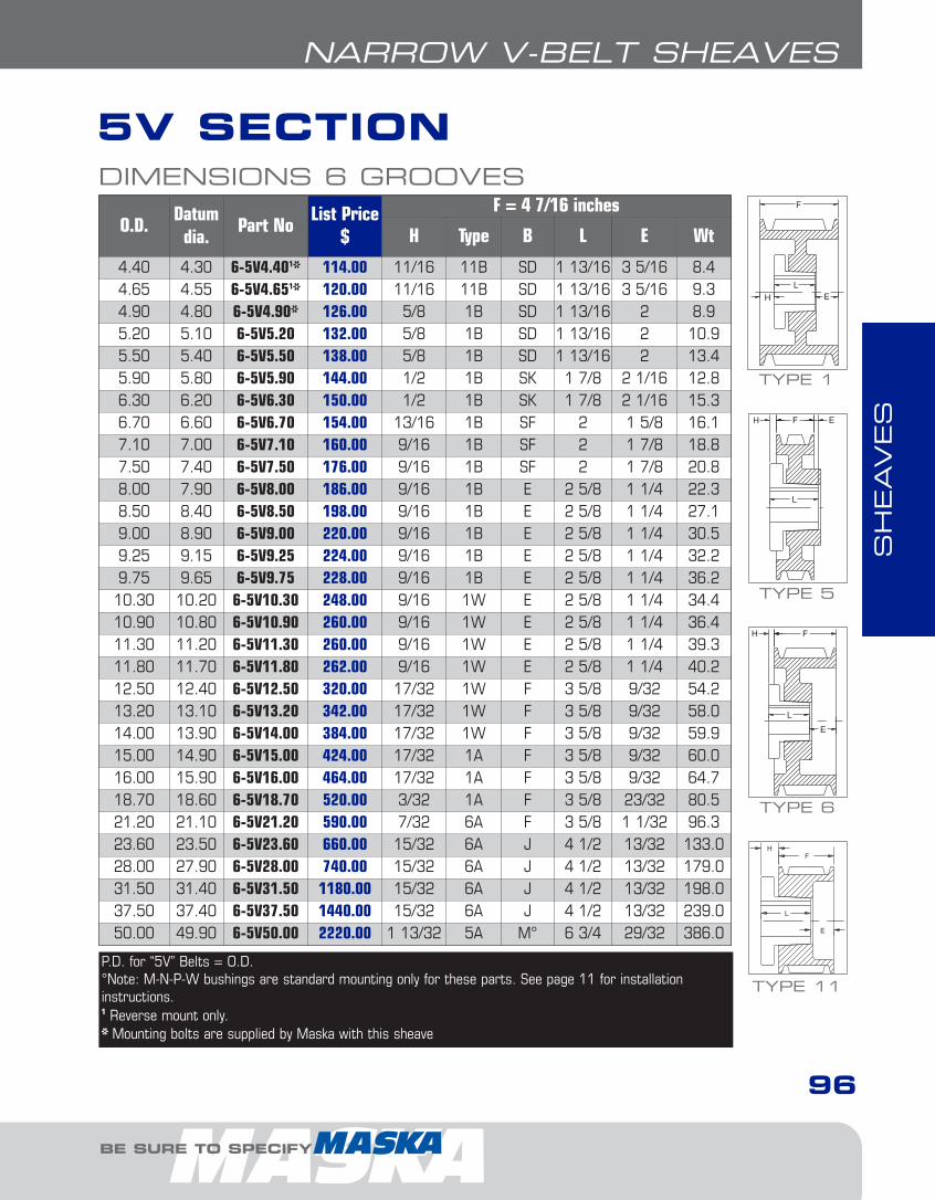
SH
EAVES
BE SURE TO SPECIFY
5V SECTION
96
NARROW V-BELT SHEAVES
DIMENSIONS 6 GROOVES
O.D.Datum
dia.Part No
List Price$
F = 4 7/16 inches
H Type B L E Wt
4.40 4.30 6-5V4.401* 114.00 11/16 11B SD 1 13/16 3 5/16 8.44.65 4.55 6-5V4.651* 120.00 11/16 11B SD 1 13/16 3 5/16 9.34.90 4.80 6-5V4.90* 126.00 5/8 1B SD 1 13/16 2 8.95.20 5.10 6-5V5.20 132.00 5/8 1B SD 1 13/16 2 10.95.50 5.40 6-5V5.50 138.00 5/8 1B SD 1 13/16 2 13.45.90 5.80 6-5V5.90 144.00 1/2 1B SK 1 7/8 2 1/16 12.86.30 6.20 6-5V6.30 150.00 1/2 1B SK 1 7/8 2 1/16 15.36.70 6.60 6-5V6.70 154.00 13/16 1B SF 2 1 5/8 16.17.10 7.00 6-5V7.10 160.00 9/16 1B SF 2 1 7/8 18.87.50 7.40 6-5V7.50 176.00 9/16 1B SF 2 1 7/8 20.88.00 7.90 6-5V8.00 186.00 9/16 1B E 2 5/8 1 1/4 22.38.50 8.40 6-5V8.50 198.00 9/16 1B E 2 5/8 1 1/4 27.19.00 8.90 6-5V9.00 220.00 9/16 1B E 2 5/8 1 1/4 30.59.25 9.15 6-5V9.25 224.00 9/16 1B E 2 5/8 1 1/4 32.29.75 9.65 6-5V9.75 228.00 9/16 1B E 2 5/8 1 1/4 36.210.30 10.20 6-5V10.30 248.00 9/16 1W E 2 5/8 1 1/4 34.410.90 10.80 6-5V10.90 260.00 9/16 1W E 2 5/8 1 1/4 36.411.30 11.20 6-5V11.30 260.00 9/16 1W E 2 5/8 1 1/4 39.311.80 11.70 6-5V11.80 262.00 9/16 1W E 2 5/8 1 1/4 40.212.50 12.40 6-5V12.50 320.00 17/32 1W F 3 5/8 9/32 54.213.20 13.10 6-5V13.20 342.00 17/32 1W F 3 5/8 9/32 58.014.00 13.90 6-5V14.00 384.00 17/32 1W F 3 5/8 9/32 59.915.00 14.90 6-5V15.00 424.00 17/32 1A F 3 5/8 9/32 60.016.00 15.90 6-5V16.00 464.00 17/32 1A F 3 5/8 9/32 64.718.70 18.60 6-5V18.70 520.00 3/32 1A F 3 5/8 23/32 80.521.20 21.10 6-5V21.20 590.00 7/32 6A F 3 5/8 1 1/32 96.323.60 23.50 6-5V23.60 660.00 15/32 6A J 4 1/2 13/32 133.028.00 27.90 6-5V28.00 740.00 15/32 6A J 4 1/2 13/32 179.031.50 31.40 6-5V31.50 1180.00 15/32 6A J 4 1/2 13/32 198.037.50 37.40 6-5V37.50 1440.00 15/32 6A J 4 1/2 13/32 239.050.00 49.90 6-5V50.00 2220.00 1 13/32 5A M° 6 3/4 29/32 386.0
P.D. for “5V” Belts = O.D.°Note: M-N-P-W bushings are standard mounting only for these parts. See page 11 for installationinstructions.1 Reverse mount only.* Mounting bolts are supplied by Maska with this sheave
TYPE 6
TYPE 11
TYPE 5
TYPE 1
4-Class-narrow1.6.qxp 2009-03-24 14:34 Page 35
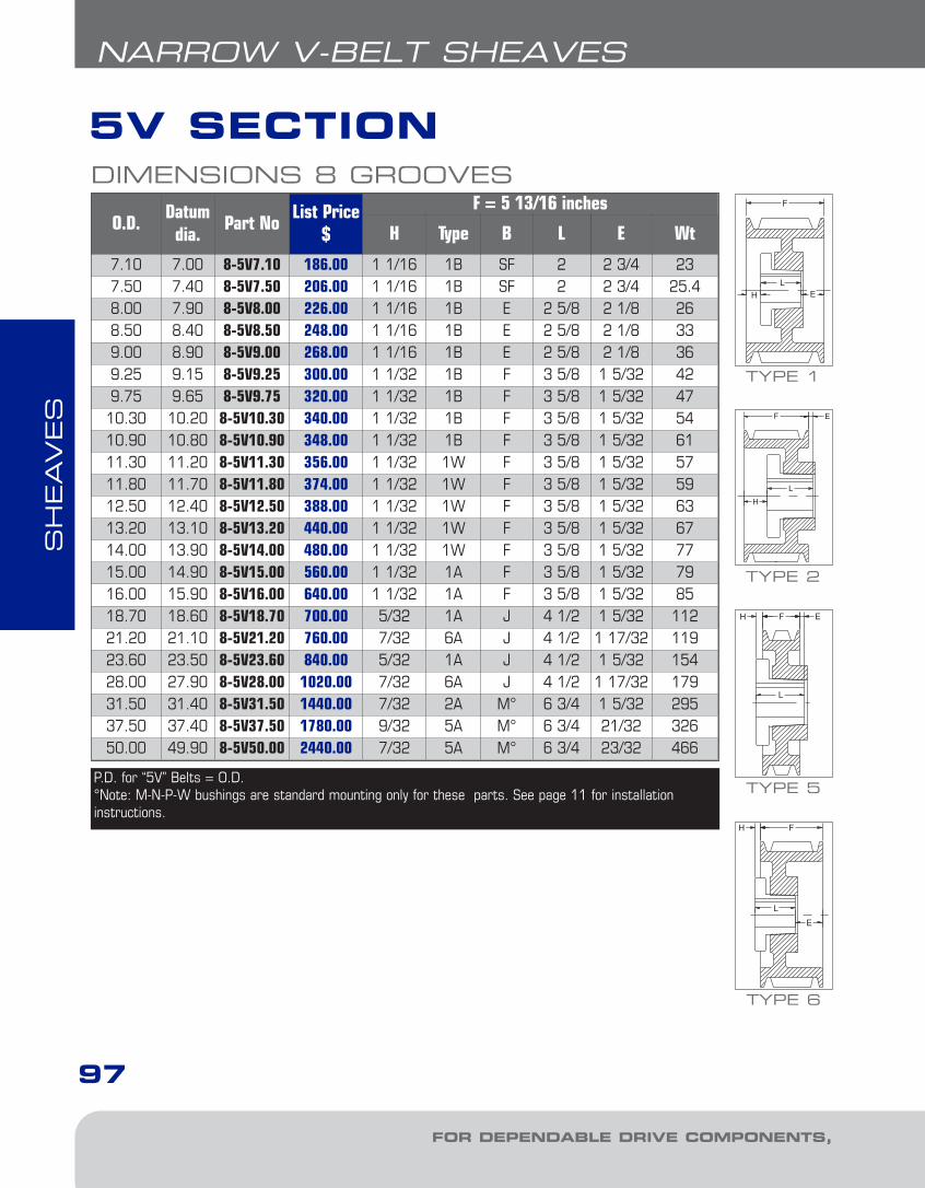
SH
EAVES
FOR DEPENDABLE DRIVE COMPONENTS, BE SURE TO SPECIFY
5V SECTION
97
NARROW V-BELT SHEAVES
DIMENSIONS 8 GROOVES
O.D.Datum
dia.Part No
List Price$
F = 5 13/16 inches
H Type B L E Wt
7.10 7.00 8-5V7.10 186.00 1 1/16 1B SF 2 2 3/4 237.50 7.40 8-5V7.50 206.00 1 1/16 1B SF 2 2 3/4 25.48.00 7.90 8-5V8.00 226.00 1 1/16 1B E 2 5/8 2 1/8 268.50 8.40 8-5V8.50 248.00 1 1/16 1B E 2 5/8 2 1/8 339.00 8.90 8-5V9.00 268.00 1 1/16 1B E 2 5/8 2 1/8 369.25 9.15 8-5V9.25 300.00 1 1/32 1B F 3 5/8 1 5/32 429.75 9.65 8-5V9.75 320.00 1 1/32 1B F 3 5/8 1 5/32 4710.30 10.20 8-5V10.30 340.00 1 1/32 1B F 3 5/8 1 5/32 5410.90 10.80 8-5V10.90 348.00 1 1/32 1B F 3 5/8 1 5/32 6111.30 11.20 8-5V11.30 356.00 1 1/32 1W F 3 5/8 1 5/32 5711.80 11.70 8-5V11.80 374.00 1 1/32 1W F 3 5/8 1 5/32 5912.50 12.40 8-5V12.50 388.00 1 1/32 1W F 3 5/8 1 5/32 6313.20 13.10 8-5V13.20 440.00 1 1/32 1W F 3 5/8 1 5/32 6714.00 13.90 8-5V14.00 480.00 1 1/32 1W F 3 5/8 1 5/32 7715.00 14.90 8-5V15.00 560.00 1 1/32 1A F 3 5/8 1 5/32 7916.00 15.90 8-5V16.00 640.00 1 1/32 1A F 3 5/8 1 5/32 8518.70 18.60 8-5V18.70 700.00 5/32 1A J 4 1/2 1 5/32 11221.20 21.10 8-5V21.20 760.00 7/32 6A J 4 1/2 1 17/32 11923.60 23.50 8-5V23.60 840.00 5/32 1A J 4 1/2 1 5/32 15428.00 27.90 8-5V28.00 1020.00 7/32 6A J 4 1/2 1 17/32 17931.50 31.40 8-5V31.50 1440.00 7/32 2A M° 6 3/4 1 5/32 29537.50 37.40 8-5V37.50 1780.00 9/32 5A M° 6 3/4 21/32 32650.00 49.90 8-5V50.00 2440.00 7/32 5A M° 6 3/4 23/32 466
P.D. for “5V” Belts = O.D.°Note: M-N-P-W bushings are standard mounting only for these parts. See page 11 for installationinstructions.
TYPE 6
TYPE 5
TYPE 1
TYPE 2
4-Class-narrow1.6.qxp 2009-03-24 14:34 Page 36
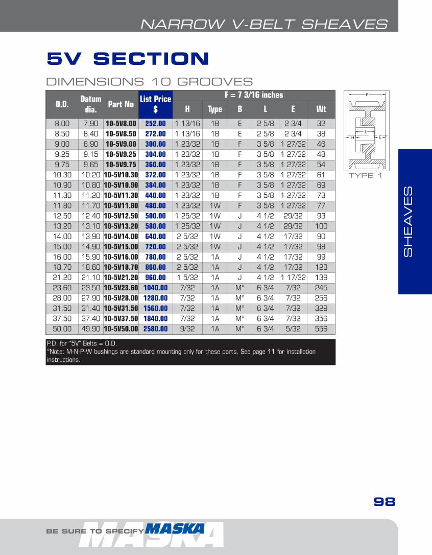
SH
EAVES
BE SURE TO SPECIFY
5V SECTION
98
NARROW V-BELT SHEAVES
DIMENSIONS 10 GROOVES
O.D.Datum
dia.Part No
List Price$
F = 7 3/16 inches
H Type B L E Wt
8.00 7.90 10-5V8.00 252.00 1 13/16 1B E 2 5/8 2 3/4 328.50 8.40 10-5V8.50 272.00 1 13/16 1B E 2 5/8 2 3/4 389.00 8.90 10-5V9.00 300.00 1 23/32 1B F 3 5/8 1 27/32 469.25 9.15 10-5V9.25 304.00 1 23/32 1B F 3 5/8 1 27/32 489.75 9.65 10-5V9.75 360.00 1 23/32 1B F 3 5/8 1 27/32 5410.30 10.20 10-5V10.30 372.00 1 23/32 1B F 3 5/8 1 27/32 6110.90 10.80 10-5V10.90 384.00 1 23/32 1B F 3 5/8 1 27/32 6911.30 11.20 10-5V11.30 440.00 1 23/32 1B F 3 5/8 1 27/32 7311.80 11.70 10-5V11.80 480.00 1 23/32 1W F 3 5/8 1 27/32 7712.50 12.40 10-5V12.50 500.00 1 25/32 1W J 4 1/2 29/32 9313.20 13.10 10-5V13.20 580.00 1 25/32 1W J 4 1/2 29/32 10014.00 13.90 10-5V14.00 640.00 2 5/32 1W J 4 1/2 17/32 9015.00 14.90 10-5V15.00 720.00 2 5/32 1W J 4 1/2 17/32 9816.00 15.90 10-5V16.00 780.00 2 5/32 1A J 4 1/2 17/32 9918.70 18.60 10-5V18.70 860.00 2 5/32 1A J 4 1/2 17/32 12321.20 21.10 10-5V21.20 960.00 1 5/32 1A J 4 1/2 1 17/32 13923.60 23.50 10-5V23.60 1040.00 7/32 1A M° 6 3/4 7/32 24528.00 27.90 10-5V28.00 1280.00 7/32 1A M° 6 3/4 7/32 25631.50 31.40 10-5V31.50 1560.00 7/32 1A M° 6 3/4 7/32 32937.50 37.40 10-5V37.50 1840.00 7/32 1A M° 6 3/4 7/32 35650.00 49.90 10-5V50.00 2580.00 9/32 1A M° 6 3/4 5/32 556
P.D. for “5V” Belts = O.D.°Note: M-N-P-W bushings are standard mounting only for these parts. See page 11 for installationinstructions.
TYPE 1
4-Class-narrow1.6.qxp 2009-03-24 14:35 Page 37

SH
EAVES
FOR DEPENDABLE DRIVE COMPONENTS, BE SURE TO SPECIFY
8V SECTION
99
NARROW V-BELT SHEAVES
DIMENSIONS 4 GROOVES
O.D.Datum
dia.Part No
List Price$
F = 4 7/8 inches
H Type B L E Wt
12.5 12.3 4-8V12.50 544.00 1/32 6W F 3 5/8 1 9/32 5613.2 13.0 4-8V13.20 552.00 1/32 6W F 3 5/8 1 9/32 6314.0 13.8 4-8V14.00 560.00 1/32 6W F 3 5/8 1 9/32 6515.0 14.8 4-8V15.00 596.00 1/32 6W F 3 5/8 1 9/32 7216.0 15.8 4-8V16.00 660.00 1/32 6A F 3 5/8 1 9/32 8017.0 16.8 4-8V17.00 720.00 1/32 1A F 3 5/8 1 7/32 9318.0 17.8 4-8V18.00 760.00 1/32 1A F 3 5/8 1 7/32 10519.0 18.8 4-8V19.00 790.00 1/32 6A F 3 5/8 1 9/32 11320.0 19.8 4-8V20.00 820.00 3/32 1A J 4 1/2 9/32 12521.2 21.0 4-8V21.20 840.00 3/32 1A J 4 1/2 9/32 13122.4 22.2 4-8V22.40 886.00 3/32 1A J 4 1/2 9/32 15024.8 24.6 4-8V24.80 1190.00 27/32 5A M° 6 3/4 1 1/32 24730.0 29.8 4-8V30.00 1350.00 27/32 5A M° 6 3/4 1 1/32 23035.5 35.3 4-8V35.50 1790.00 27/32 5A M° 6 3/4 1 1/32 32940.0 39.8 4-8V40.00 1970.00 27/32 5A M° 6 3/4 1 1/32 32544.5 44.3 4-8V44.50 2590.00 27/32 5A M° 6 3/4 1 1/32 43453.0 52.8 4-8V53.00 3240.00 27/32 5A M° 6 3/4 1 1/32 425
P.D. for “8V” Belts = O.D.°Note: M-N-P-W bushings are standard mounting only for these parts. See page 11 for installation instructions.
TYPE 6
TYPE 5
TYPE 1
4-Class-narrow1.6.qxp 2009-03-24 14:35 Page 38
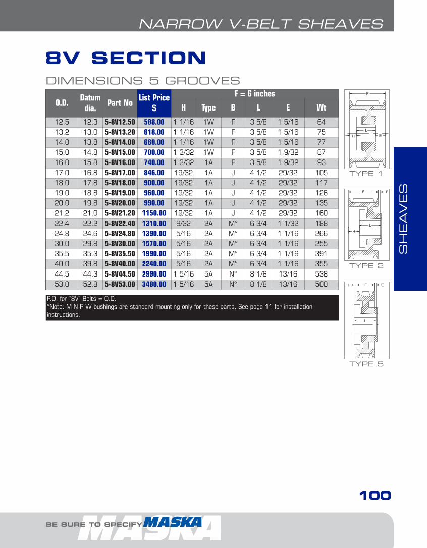
SH
EAVES
BE SURE TO SPECIFY
8V SECTION
100
NARROW V-BELT SHEAVES
DIMENSIONS 5 GROOVES
O.D.Datum
dia.Part No
List Price$
F = 6 inches
H Type B L E Wt
12.5 12.3 5-8V12.50 588.00 1 1/16 1W F 3 5/8 1 5/16 6413.2 13.0 5-8V13.20 618.00 1 1/16 1W F 3 5/8 1 5/16 7514.0 13.8 5-8V14.00 660.00 1 1/16 1W F 3 5/8 1 5/16 7715.0 14.8 5-8V15.00 700.00 1 3/32 1W F 3 5/8 1 9/32 8716.0 15.8 5-8V16.00 740.00 1 3/32 1A F 3 5/8 1 9/32 9317.0 16.8 5-8V17.00 846.00 19/32 1A J 4 1/2 29/32 10518.0 17.8 5-8V18.00 900.00 19/32 1A J 4 1/2 29/32 11719.0 18.8 5-8V19.00 960.00 19/32 1A J 4 1/2 29/32 12620.0 19.8 5-8V20.00 990.00 19/32 1A J 4 1/2 29/32 13521.2 21.0 5-8V21.20 1150.00 19/32 1A J 4 1/2 29/32 16022.4 22.2 5-8V22.40 1310.00 9/32 2A M° 6 3/4 1 1/32 18824.8 24.6 5-8V24.80 1390.00 5/16 2A M° 6 3/4 1 1/16 26630.0 29.8 5-8V30.00 1570.00 5/16 2A M° 6 3/4 1 1/16 25535.5 35.3 5-8V35.50 1990.00 5/16 2A M° 6 3/4 1 1/16 39140.0 39.8 5-8V40.00 2240.00 5/16 2A M° 6 3/4 1 1/16 35544.5 44.3 5-8V44.50 2990.00 1 5/16 5A N° 8 1/8 13/16 53853.0 52.8 5-8V53.00 3480.00 1 5/16 5A N° 8 1/8 13/16 500
P.D. for “8V” Belts = O.D.°Note: M-N-P-W bushings are standard mounting only for these parts. See page 11 for installation instructions.
TYPE 5
TYPE 1
TYPE 2
4-Class-narrow1.6.qxp 2009-03-24 14:35 Page 39

SH
EAVES
FOR DEPENDABLE DRIVE COMPONENTS, BE SURE TO SPECIFY
8V SECTION
101
NARROW V-BELT SHEAVES
DIMENSIONS 6 GROOVES
O.D.Datum
dia.Part No
List Price$
F = 7 1/8 inches
H Type B L E Wt
12.5 12.3 6-8V12.50 618.00 2 3/32 1B F 3 5/8 1 13/32 7913.2 13.0 6-8V13.20 660.00 1 1/16 1W F 3 5/8 2 7/16 8614.0 13.8 6-8V14.00 722.00 1 1/16 1W F 3 5/8 2 7/16 9215.0 14.8 6-8V15.00 774.00 1 5/32 1W J 4 1/2 1 15/32 9916.0 15.8 6-8V16.00 824.00 1 5/32 1W J 4 1/2 1 15/32 11917.0 16.8 6-8V17.00 928.00 1 5/32 1A J 4 1/2 1 15/32 12518.0 17.8 6-8V18.00 1000.00 1 5/32 1A J 4 1/2 1 15/32 13119.0 18.8 6-8V19.00 1040.00 1 5/32 1A J 4 1/2 1 15/32 14620.0 19.8 6-8V20.00 1190.00 1 9/32 2A M° 6 3/4 29/32 15321.2 21.0 6-8V21.20 1320.00 1 9/32 2W M° 6 3/4 29/32 17022.4 22.2 6-8V22.40 1560.00 1 9/32 2A M° 6 3/4 29/32 20524.8 24.6 6-8V24.80 1590.00 9/32 1A M° 6 3/4 3/32 28530.0 29.8 6-8V30.00 1610.00 9/32 1A M° 6 3/4 3/32 29135.5 35.3 6-8V35.50 2190.00 3/16 5A N° 8 1/8 13/16 46740.0 39.8 6-8V40.00 2440.00 3/16 2A N° 8 1/8 1 3/16 40144.5 44.3 6-8V44.50 3390.00 3/16 5A N° 8 1/8 13/16 57353.0 52.8 6-8V53.00 3720.00 3/16 5A N° 8 1/8 13/16 52058.0 57.8 - - - - - - - -63.0 62.8 6-8V63.00 6190.00 3/4 5A P° 9 3/8 1 1/2 89071.0 70.8 6-8V71.00 9000.00 3/4 5A P° 9 3/8 1 1/2 1131
P.D. for “8V” Belts = O.D.°Note: M-N-P-W bushings are standard mounting only for these parts. See page 11 for installationinstructions.
TYPE 1
TYPE 2
TYPE 5
4-Class-narrow1.6.qxp 2009-03-24 14:35 Page 40
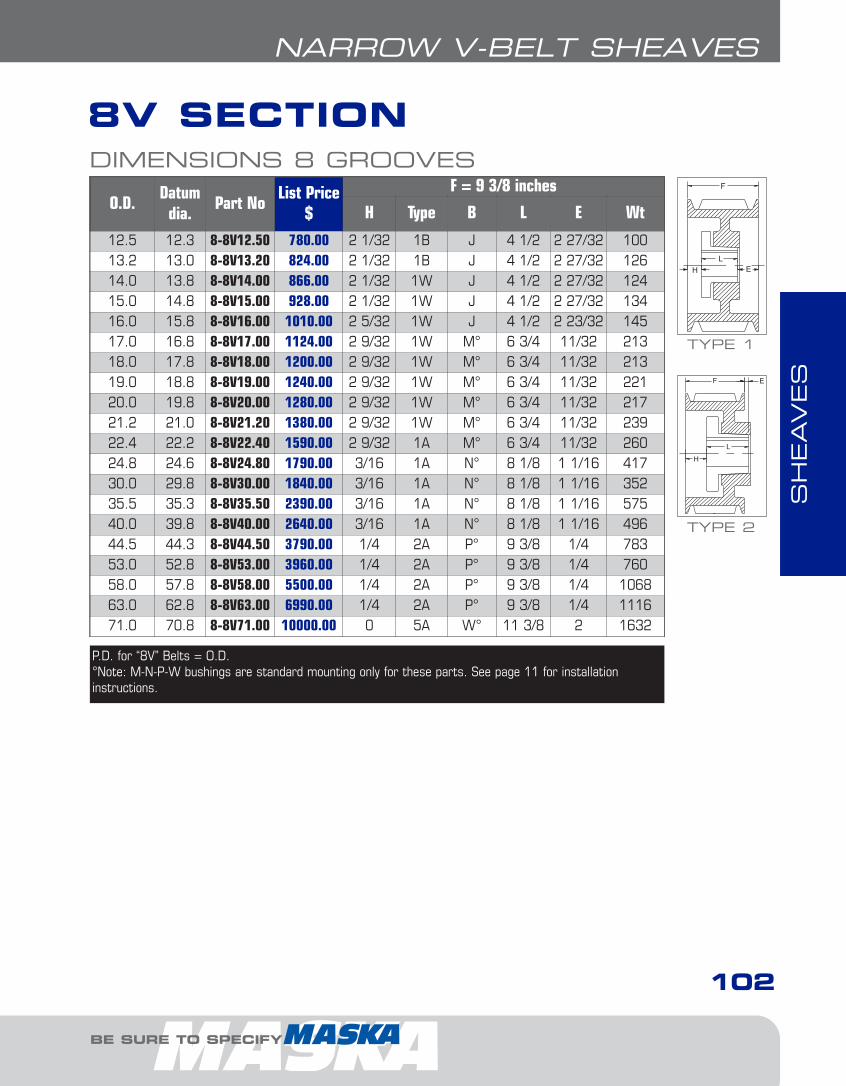
SH
EAVES
BE SURE TO SPECIFY
8V SECTION
102
NARROW V-BELT SHEAVES
DIMENSIONS 8 GROOVES
O.D.Datum
dia.Part No
List Price$
F = 9 3/8 inches
H Type B L E Wt
12.5 12.3 8-8V12.50 780.00 2 1/32 1B J 4 1/2 2 27/32 10013.2 13.0 8-8V13.20 824.00 2 1/32 1B J 4 1/2 2 27/32 12614.0 13.8 8-8V14.00 866.00 2 1/32 1W J 4 1/2 2 27/32 12415.0 14.8 8-8V15.00 928.00 2 1/32 1W J 4 1/2 2 27/32 13416.0 15.8 8-8V16.00 1010.00 2 5/32 1W J 4 1/2 2 23/32 14517.0 16.8 8-8V17.00 1124.00 2 9/32 1W M° 6 3/4 11/32 21318.0 17.8 8-8V18.00 1200.00 2 9/32 1W M° 6 3/4 11/32 21319.0 18.8 8-8V19.00 1240.00 2 9/32 1W M° 6 3/4 11/32 22120.0 19.8 8-8V20.00 1280.00 2 9/32 1W M° 6 3/4 11/32 21721.2 21.0 8-8V21.20 1380.00 2 9/32 1W M° 6 3/4 11/32 23922.4 22.2 8-8V22.40 1590.00 2 9/32 1A M° 6 3/4 11/32 26024.8 24.6 8-8V24.80 1790.00 3/16 1A N° 8 1/8 1 1/16 41730.0 29.8 8-8V30.00 1840.00 3/16 1A N° 8 1/8 1 1/16 35235.5 35.3 8-8V35.50 2390.00 3/16 1A N° 8 1/8 1 1/16 57540.0 39.8 8-8V40.00 2640.00 3/16 1A N° 8 1/8 1 1/16 49644.5 44.3 8-8V44.50 3790.00 1/4 2A P° 9 3/8 1/4 78353.0 52.8 8-8V53.00 3960.00 1/4 2A P° 9 3/8 1/4 76058.0 57.8 8-8V58.00 5500.00 1/4 2A P° 9 3/8 1/4 106863.0 62.8 8-8V63.00 6990.00 1/4 2A P° 9 3/8 1/4 111671.0 70.8 8-8V71.00 10000.00 0 5A W° 11 3/8 2 1632
TYPE 1
TYPE 2
P.D. for “8V” Belts = O.D.°Note: M-N-P-W bushings are standard mounting only for these parts. See page 11 for installationinstructions.
4-Class-narrow1.6.qxp 2009-03-24 14:35 Page 41

SH
EAVES
FOR DEPENDABLE DRIVE COMPONENTS, BE SURE TO SPECIFY
8V SECTION
103
NARROW V-BELT SHEAVES
DIMENSIONS 10 GROOVES
O.D.Datum
dia.Part No
List Price$
F = 11 5/8 inches
H Type B L E Wt
12.5 12.3 10-8V12.50 948.00 2 5/32 1B J 4 1/2 4 31/32 14813.2 13.0 10-8V13.20 1114.00 2 5/32 1B J 4 1/2 4 31/32 14814.0 13.8 10-8V14.00 1278.00 2 5/32 1B J 4 1/2 4 31/32 16015.0 14.8 10-8V15.00 1442.00 2 9/32 1B M° 6 3/4 2 19/32 25916.0 15.8 10-8V16.00 1608.00 2 9/32 1B M° 6 3/4 2 19/32 29617.0 16.8 10-8V17.00 1648.00 2 9/32 1W M° 6 3/4 2 19/32 26918.0 17.8 10-8V18.00 1720.00 2 9/32 1W M° 6 3/4 2 19/32 28219.0 18.8 10-8V19.00 1760.00 2 9/32 1W M° 6 3/4 2 19/32 30020.0 19.8 10-8V20.00 1860.00 2 9/32 1W M° 6 3/4 2 19/32 31821.2 21.0 10-8V21.20 2040.00 2 9/32 1W M° 6 3/4 2 19/32 34022.4 22.2 10-8V22.40 2246.00 3/16 1A N° 8 1/8 3 5/16 41024.8 24.6 10-8V24.80 2290.00 3/16 1A N° 8 1/8 3 5/16 46330.0 29.8 10-8V30.00 2350.00 3/16 1A N° 8 1/8 3 5/16 55735.5 35.3 10-8V35.50 2790.00 1/4 1A P° 9 3/8 2 70640.0 39.8 10-8V40.00 3350.00 1/4 1A P° 9 3/8 2 81744.5 44.3 10-8V44.50 4190.00 1/4 1A P° 9 3/8 2 85453.0 52.8 10-8V53.00 5000.00 1/4 1A P° 9 3/8 2 119858.0 57.8 10-8V58.00 7000.00 3/8 2A W° 11 3/8 1/8 130063.0 62.8 10-8V63.00 9000.00 3/8 2A W° 11 3/8 1/8 141271.0 70.8 10-8V71.00 11500.00 3/8 2A W° 11 3/8 1/8 1771
TYPE 1
TYPE 2
P.D. for “8V” Belts = O.D.°Note: M-N-P-W bushings are standard mounting only for these parts. See page 11 for installationinstructions.
4-Class-narrow1.6.qxp 2009-03-24 14:35 Page 42

SH
EAVES
BE SURE TO SPECIFY
8V SECTION
104
NARROW V-BELT SHEAVES
DIMENSIONS 12 GROOVES
O.D.Datum
dia.Part No
List Price$
F = 13 7/8 inches
H Type B L E Wt
12.5 12.3 12-8V12.50 2080.00 2 9/32 1B M° 6 3/4 4 27/32 19713.2 13.0 12-8V13.20 2120.00 2 9/32 1B M° 6 3/4 4 27/32 21914.0 13.8 12-8V14.00 2160.00 2 9/32 1B M° 6 3/4 4 27/32 24515.0 14.8 12-8V15.00 2200.00 2 9/32 1B M° 6 3/4 4 27/32 28016.0 15.8 12-8V16.00 2240.00 2 9/32 1B M° 6 3/4 4 27/32 31917.0 16.8 12-8V17.00 2280.00 2 9/32 1B M° 6 3/4 4 27/32 32118.0 17.8 12-8V18.00 2320.00 2 9/32 1B M° 6 3/4 4 27/32 33719.0 18.8 12-8V19.00 2400.00 3/16 1B N° 8 1/8 5 9/16 38020.0 19.8 12-8V20.00 2480.00 3/16 1W N° 8 1/8 5 9/16 40221.2 21.0 12-8V21.20 2560.00 3/16 1W N° 8 1/8 5 9/16 42022.4 22.2 12-8V22.40 2640.00 3/16 1A N° 8 1/8 5 9/16 45824.8 24.6 12-8V24.80 3000.00 3/16 1A N° 8 1/8 5 9/16 51630.0 29.8 12-8V30.00 3380.00 1/4 1A P° 9 3/8 4 1/4 67135.5 35.3 12-8V35.50 3660.00 1/4 1A P° 9 3/8 4 1/4 79840.0 39.8 12-8V40.00 5000.00 1/4 1A P° 9 3/8 4 1/4 90944.5 44.3 12-8V44.50 6500.00 1/4 1A P° 9 3/8 4 1/4 98253.0 52.8 12-8V53.00 8000.00 5/8 1A W° 11 3/8 1 7/8 145658.0 57.8 12-8V58.00 9000.00 5/8 1A W° 11 3/8 1 7/8 150063.0 62.8 12-8V63.00 10000.00 5/8 1A W° 11 3/8 1 7/8 154071.0 70.8 12-8V71.00 13000.00 5/8 1A W° 11 3/8 1 7/8 1912
TYPE 1
P.D. for “8V” Belts = O.D.°Note: M-N-P-W bushings are standard mounting only for these parts. See page 11 for installationinstructions.
4-Class-narrow1.6.qxp 2009-03-24 14:35 Page 43
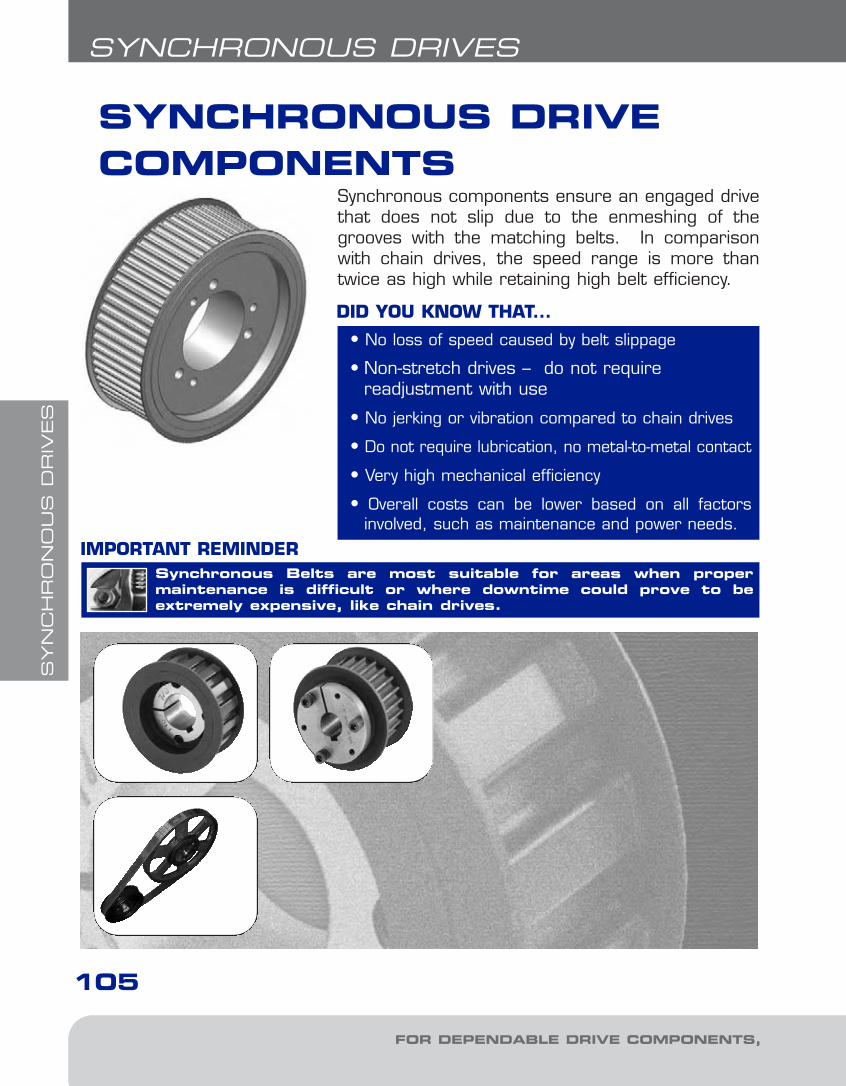
SYN
CH
RO
NO
US
DR
IVES
105
FOR DEPENDABLE DRIVE COMPONENTS, BE SURE TO SPECIFY
Synchronous Belts are most suitable for areas when proper maintenance is difficult or where downtime could prove to beextremely expensive, like chain drives.
IMPORTANT REMINDER
SYNCHRONOUS DRIVECOMPONENTS
• No loss of speed caused by belt slippage
• Non-stretch drives – do not require readjustment with use
• No jerking or vibration compared to chain drives
• Do not require lubrication, no metal-to-metal contact
• Very high mechanical efficiency
• Overall costs can be lower based on all factorsinvolved, such as maintenance and power needs.
DID YOU KNOW THAT...
Synchronous components ensure an engaged drivethat does not slip due to the enmeshing of thegrooves with the matching belts. In comparisonwith chain drives, the speed range is more thantwice as high while retaining high belt efficiency.
SYNCHRONOUS DRIVES
5-Synchronous1.8.qxp 2009-03-19 14:08 Page 2
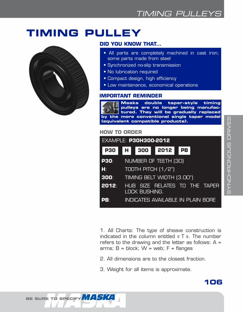
SYN
CH
RO
NO
US
DR
IVES
TIMING PULLEYS
106
BE SURE TO SPECIFY
TIMING PULLEY
EXAMPLE: P30H300-2012
P30 H
P30: NUMBER OF TEETH (30)
H: TOOTH PITCH (1/2’’)
300: TIMING BELT WIDTH (3.00’’)
2012: HUB SIZE RELATES TO THE TAPERLOCK BUSHING.
PB: INDICATES AVAILABLE IN PLAIN BORE
HOW TO ORDER
300 2012 PB
• All parts are completely machined in cast iron;some parts made from steel
• Synchronized no-slip transmission• No lubrication required• Compact design, high efficiency• Low maintenance, economical operations
DID YOU KNOW THAT...
Maska double taper-style timing pulleys are no longer being manufac-tured. They will be gradually replaced
by the more conventional single taper model(equivalent compatible products).
IMPORTANT REMINDER
1. All Charts: The type of sheave construction isindicated in the column entitled « T ». The numberrefers to the drawing and the letter as follows: A =arms; B = block; W = web; F = flanges
2. All dimensions are to the closest fraction.
3. Weight for all items is approximate.
5-Synchronous1.8.qxp 2009-03-19 14:08 Page 3
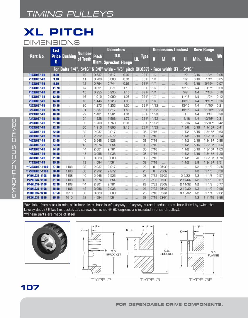
SYN
CH
RO
NO
US
DR
IVES
FOR DEPENDABLE DRIVE COMPONENTS, BE SURE TO SPECIFY
107
TIMING PULLEYS
XL PITCHDIMENSIONS
Part NoList
Price$
BushingNumberof Teeth
DiametersType
Dimensions (inches) Bore RangeWtPitch
Diam.O.D.
I.D. K M N H Min. Max.Sprocket Flange
For Belts 1/4”, 5/16” & 3/8” wide - 1/5” pitch (XL037) - Face width (F) = 9/16”P10XL037-PB 9.00 … 10 0.637 0.617 0.91 … 3B F 1/4 … … 1/2 3/16 1/4* 0.05P11XL037-PB 9.40 … 11 0.700 0.680 0.91 … 3B F 1/4 … … 1/2 3/16 1/4* 0.05P12XL037-PB 9.80 … 12 0.764 0.744 0.98 … 3B F 1/4 … … 1/2 3/16 5/16* 0.07P14XL037-PB 11.70 … 14 0.891 0.871 1.10 … 3B F 1/4 … … 9/16 1/4 3/8* 0.09P15XL037-PB 12.10 … 15 0.955 0.935 1.10 … 3B F 1/4 … … 5/8 1/4 7/16* 0.10P16XL037-PB 12.80 … 16 1.019 0.999 1.26 … 3B F 1/4 … … 11/16 1/4 1/2* 0.12P18XL037-PB 14.30 … 18 1.146 1.126 1.38 … 3B F 1/4 … … 13/16 1/4 9/16* 0.16P20XL037-PB 15.10 … 20 1.273 1.253 1.50 … 3B F 11/32 … … 15/16 1/4 11/16* 0.21P21XL037-PB 16.20 … 21 1.337 1.317 1.50 3B F 11/32 … … 15/16 1/4 11/16* 0.23P22XL037-PB 16.60 … 22 1.401 1.381 1.61 … 3B F 11/32 … … 1 1/4 3/4* 0.26P24XL037-PB 18.50 … 24 1.528 1.508 1.73 … 3B F 11/32 … … 1 1/16 1/4 13/16* 0.31P28XL037-PB 21.10 … 28 1.783 1.763 2.01 … 3B F 11/32 … … 1 3/16 1/4 15/16* 0.42P30XL037-PB 22.20 … 30 1.910 1.890 2.13 … 3B F 11/32 … … 1 3/8 5/16 1 1/16* 0.41P32XL037-PB 22.60 … 32 2.037 2.017 … … 3B 7/16 … … 1 1/2 5/16 1 3/16* 0.63P36XL037-PB 23.00 … 36 2.292 2.272 … … 3B 7/16 … … 1 1/2 5/16 1 3/16* 0.74P40XL037-PB 23.40 … 40 2.546 2.526 … … 3B 7/16 … … 1 1/2 5/16 1 3/16* 0.88P42XL037-PB 23.80 … 42 2.674 2.654 … … 3B 7/16 … … 1 1/2 5/16 1 3/16* 0.96P44XL037-PB 24.50 … 44 2.801 2.781 … … 3B 7/16 … … 1 1/2 5/16 1 3/16* 1.03P48XL037-PB 26.00 … 48 3.056 3.036 … … 3B 7/16 … … 1 1/2 5/16 1 3/16* 1.20P60XL037-PB 31.30 … 60 3.820 3.800 … … 3B 7/16 … … 1 1/2 3/8 1 3/16* 1.78P72XL037-PB 39.20 … 72 4.584 4.564 … … 3B 7/16 … … 1 1/2 3/8 1 3/16* 2.51
**P32XL037-1108 27.50 1108 32 2.037 2.017 … … 2B 0 25/32 … … 1/2 1 1/8 0.25**P36XL037-1108 28.40 1108 36 2.292 2.272 … … 2B 0 25/32 … … 1/2 1 1/8 0.38P40XL037-1108 29.50 1108 40 2.546 2.526 … … 2B 7/32 25/32 … 2 5/32 1/2 1 1/8 0.57P42XL037-1108 31.10 1108 42 2.674 2.654 … … 2B 7/32 25/32 … 2 17/64 1/2 1 1/8 0.67P44XL037-1108 32.50 1108 44 2.801 2.781 … … 2B 7/32 25/32 … 2 11/32 1/2 1 1/8 0.77P48XL037-1108 35.90 1108 48 3.056 3.036 … … 2B 7/32 25/32 … 2 19/32 1/2 1 1/8 0.99P60XL037-1210 37.50 1210 60 3.820 3.800 … … 2B 7/16 63/64 … 3 13/32 1/2 1 1/4 2.02P72XL037-1610 39.10 1610 72 4.584 4.564 … … 2B 7/16 63/64 … 4 1/2 1 11/16 2.86
*Available from stock in min. plain bore. Max. bore is w/o keyway. (If keyway is used, reduce max. bore listed by twice the keyway depth.) ((Two hex-socket set screws furnished @ 90 degrees are included in price of pulley.))**These parts are made of steel
TYPE 3 TYPE 3F
HO.D.
SROCKET HHM O.D.SPROCKET
TYPE 2
5-Synchronous1.8.qxp 2009-03-19 14:08 Page 4
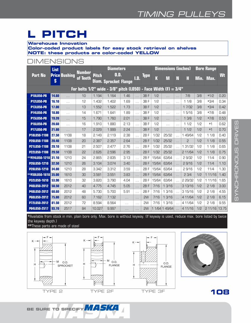
SYN
CH
RO
NO
US
DR
IVES
BE SURE TO SPECIFY
108
TIMING PULLEYS
DIMENSIONS
Part NoList
Price$
BushingNumberof Teeth
DiametersType
Dimensions (inches) Bore RangeWtPitch
Diam.O.D.
I.D. K M N H Min. Max.Sprocket Flange
For belts 1/2” wide - 3/8” pitch (L050) - Face Width (F) = 3/4”P10L050-PB 14.60 … 10 1.194 1.164 1.46 … 3B F 1/2 … … 7/8 3/8 *1/2 0.20
P12L050-PB 16.10 … 12 1.432 1.402 1.69 … 3B F 1/2 … … 1 1/8 3/8 *3/4 0.34
P13L050-PB 17.00 … 13 1.552 1.522 1.73 … 3B F 1/2 … … 1 7/32 3/8 *3/4 0.42
P14L050-PB 18.80 … 14 1.671 1.641 1.89 … 3B F 1/2 … … 1 5/16 3/8 *7/8 0.48
P15L050-PB 19.20 … 15 1.790 1.760 2.01 … 3B F 1/2 … … 1 3/8 1/2 *7/8 0.53
P16L050-PB 20.60 … 16 1.910 1.880 2.13 … 3B F 1/2 … … 1 1/2 1/2 *1 0.62
P17L050-PB 21.80 … 17 2.029 1.999 2.24 … 3B F 1/2 … … 1 1/2 1/2 *1 0.70
P18L050-1108 27.50 1108 18 2.149 2.119 2.38 … 2B F 1/32 25/32 … 1 49/64 1/2 1 1/8 0.40
P20L050-1108 28.40 1108 20 2.387 2.357 2.64 … 2B F 1/32 25/32 … 2 1/2 1 1/8 0.55
P21L050-1108 29.10 1108 21 2.507 2.477 2.76 … 2B F 1/32 25/32 … 1 31/32 1/2 1 1/8 0.65
P22L050-1108 29.50 1108 22 2.626 2.596 2.95 … 2B F 1/32 25/32 … 2 11/64 1/2 1 1/8 0.75
**P24L050-1210 31.10 1210 24 2.865 2.835 3.13 … 2B F 15/64 63/64 … 2 9/32 1/2 11/4 0.90
P26L050-1210 32.50 1210 26 3.104 3.074 3.40 … 2B F 15/64 63/64 … 2 9/16 1/2 11/4 1.10
P28L050-1210 34.80 1210 28 3.342 3.312 3.59 … 2B F 15/64 63/64 … 2 9/16 1/2 11/4 1.30
**P30L050-1610 35.00 1610 30 3.581 3.551 3.83 … 2B F 15/64 63/64 … 2 3/4 1/2 1 11/16 1.40
P32L050-1610 53.90 1610 32 3.820 3.790 4.04 … 2B F 15/64 63/64 … 2 29/32 1/2 1 11/16 1.65
P40L050-2012 58.50 2012 40 4.775 4.745 5.05 … 2B F 7/16 1 3/16 … 3 13/16 1/2 2 1/8 3.00
P48L050-2012 68.60 2012 48 5.730 5.700 5.91 … 2B F 7/16 1 3/16 … 3 15/16 1/2 2 1/8 4.55
P60L050-2012 75.80 2012 60 7.162 7.132 … … 2W 7/16 1 3/16 … 4 11/64 1/2 2 1/8 6.15
P72L050-2012 81.50 2012 72 8.594 8.564 … … 2W 7/16 1 3/16 … 4 11/64 1/2 2 1/8 9.55
P84L050-2517 93.70 2517 84 10.027 9.997 … … 2W 1 1/64 1 49/64 … 4 11/16 1/2 2 11/16 13.75
*Available from stock in min. plain bore only. Max. bore is without keyway. (If keyway is used, reduce max. bore listed by twicethe keyway depth.)**These parts are made of steel
Warehouse InnovationColor-coded product labels for easy stock retrieval on shelvesNOTE: these products are color-coded YELLOW
L PITCH
TYPE 2F TYPE 3F
HM
HHM O.D.SPROCKET
TYPE 2
5-Synchronous1.8.qxp 2009-03-19 14:08 Page 5

SYN
CH
RO
NO
US
DR
IVES
109
TIMING PULLEYS
FOR DEPENDABLE DRIVE COMPONENTS, BE SURE TO SPECIFY
L PITCH
DIMENSIONS
Part NoList
Price$
BushingNumberof Teeth
DiametersType
Dimensions (inches) Bore RangeWtPitch
Diam.O.D.
I.D. K M N H Min. Max.Sprocket Flange
For Belts 3/4” wide - 3/8” pitch (L075) - Face width (F) = 1”P12L075-PB 19.50 … 12 1.432 1.402 1.69 … 3B F 1/2 … … 1 1/8 3/8 *3/4 0.43
P13L075-PB 19.90 … 13 1.552 1.522 1.73 … 3B F 1/2 … … 1 7/32 3/8 *3/4 0.50
P14L075-PB 21.30 … 14 1.671 1.641 1.89 … 3B F 1/2 … … 1 5/16 3/8 *7/8 0.53
P15L075-PB 22.00 … 15 1.790 1.760 2.01 … 3B F 1/2 … … 1 3/8 1/2 *7/8 0.60
P16L075-PB 22.80 … 16 1.910 1.880 2.13 … 3B F 1/2 … … 1 1/2 1/2 *1 0.70
P17L075-PB 24.00 … 17 2.029 1.999 2.24 … 3B F 1/2 … … 1 1/2 1/2 *1 0.80
P18L075-1108 29.10 1108 18 2.149 2.119 2.38 1.60 1B F 13/64 25/32 0 … 1/2 1 1/8 0.45
P20L075-1108 30.50 1108 20 2.387 2.357 2.64 1.77 1B F 13/64 25/32 0 … 1/2 1 1/8 0.65
P22L075-1108 33.20 1108 22 2.626 2.596 2.95 1.89 1B F 13/64 25/32 0 … 1/2 1 1/8 0.90
P24L075-1210 34.80 1210 24 2.865 2.835 3.13 … 2B F 0 63/64 … … 1/2 1 1/4 0.90
P26L075-1210 36.80 1210 26 3.104 3.074 3.40 … 2B F 0 63/64 … … 1/2 1 1/4 1.25
P28L075-1610 39.50 1610 28 3.342 3.312 3.59 … 2B F 0 63/64 … … 1/2 1 11/16 1.20
P30L075-1610 42.50 1610 30 3.581 3.551 3.83 … 2B F 0 63/64 … … 1/2 1 11/16 1.85
P32L075-1610 45.20 1610 32 3.820 3.790 4.04 … 2B F 0 63/64 … … 1/2 1 11/16 1.85
P40L075-2012 62.50 2012 40 4.775 4.745 5.05 … 2B F 13/64 1 3/16 … 3 13/16 1/2 2 1/8 3.30
P48L075-2012 71.70 2012 48 5.730 5.700 5.91 … 2B F 13/64 1 3/16 … 3 15/16 1/2 2 1/8 5.35
P60L075-2012 82.20 2012 60 7.162 7.132 … … 2W 13/64 1 3/16 … 4 11/64 1/2 2 1/8 6.45
P72L075-2012 89.20 2012 72 8.594 8.564 … … 2W 13/64 1 3/16 … 4 11/64 1/2 2 1/8 9.70
P84L075-2517 109.60 2517 84 10.027 9.997 ... … 2W 25/32 1 49/64 … 4 11/16 1/2 2 11/16 14.55
*Available from stock in min. plain bore only. Max. bore is without keyway. (If keyway is used, reduce max. bore listed by twicethe keyway depth.)
Warehouse InnovationColor-coded product labels for easy stock retrieval on shelvesNOTE: these products are color-coded YELLOW
TYPE 2 TYPE 2F
HM O.D.SPROCKET H
MI.D.
M
N
TYPE 1F TYPE 3F
H
5-Synchronous1.8.qxp 2009-03-19 14:08 Page 6

SYN
CH
RO
NO
US
DR
IVES
110
TIMING PULLEYS
BE SURE TO SPECIFY
DIMENSIONS
Part NoList
Price$
BushingNumberof Teeth
DiametersType
Dimensions (inches) Bore RangeWtPitch
Diam.O.D.
I.D. K M N H Min. Max.Sprocket Flange
For Belts 1” wide - 3/8” pitch (L100) - Face width (F) = 1 1/4”P13L100-PB 22.50 … 13 1.552 1.522 1.73 … 3B F 1/2 … … 1 7/32 3/8 *3/4 0.60
P14L100-PB 23.30 … 14 1.671 1.641 1.89 … 3B F 1/2 … … 1 5/16 3/8 *7/8 0.65
P15L100-PB 24.00 … 15 1.790 1.760 2.01 … 3B F 1/2 … … 1 3/8 1/2 *7/8 0.74
P16L100-PB 24.80 … 16 1.910 1.880 2.13 … 3B F 1/2 … … 1 1/2 1/2 *1 0.80
P17L100-PB 26.30 … 17 2.029 1.999 2.24 … 3B F 1/2 … … 1 1/2 1/2 *1 1.00
P18L100-1108 32.00 1108 18 2.149 2.119 2.38 1.60 1B F 15/32 25/32 0 … 1/2 1 1/8 0.55
P20L100-1108 33.60 1108 20 2.387 2.357 2.64 1.77 1B F 15/32 25/32 0 … 1/2 1 1/8 0.80
P22L100-1108 36.40 1108 22 2.626 2.596 2.95 1.89 1B F 15/32 25/32 0 … 1/2 1 1/8 1.05
P24L100-1210 37.50 1210 24 2.865 2.835 3.13 2.24 1B F 9/32 63/64 0 … 1/2 1 1/4 1.25
P26L100-1210 40.00 1210 26 3.104 3.074 3.40 2.36 1B F 9/32 63/64 0 … 1/2 1 1/4 1.45
P28L100-1610 42.50 1610 28 3.342 3.312 3.59 2.54 1B F 9/32 63/64 0 … 1/2 1 11/16 1.45
P30L100-1610 46.10 1610 30 3.581 3.551 3.83 2.80 1B F 9/32 63/64 0 … 1/2 1 11/16 1.75
P32L100-1610 49.80 1610 32 3.820 3.790 4.04 2.95 1B F 9/32 63/64 0 … 1/2 1 11/16 2.15
P40L100-2012 67.90 2012 40 4.775 4.745 5.05 3.78 1B F 5/64 1 3/16 0 … 1/2 2 1/8 3.75
P48L100-2012 78.80 2012 48 5.730 5.700 5.91 4.72 1B F 5/64 1 3/16 0 … 1/2 2 1/8 6.10
P60L100-2012 92.70 2012 60 7.162 7.132 … 6.54 1W 5/64 1 3/16 0 … 1/2 2 1/8 6.95
P72L100-2012 112.20 2012 72 8.594 8.564 … 7.95 1W 5/64 1 3/16 0 … 1/2 2 1/8 10.60
P84L100-2517 128.70 2517 84 10.027 9.997 … … 2W 33/64 1 49/64 … 4 11/16 1/2 2 11/16 15.15
*Available from stock in min. plain bore. Max. bore is w/o keyway. (If keyway is used, reduce max. bore listed by twice the keyway depth.)
Warehouse InnovationColor-coded product labels for easy stock retrieval on shelvesNOTE: these products are color-coded YELLOW
TYPE 1F TYPE 2
I.D.
M
NH
M O.D.SPROCKETI.D.
M
N O.D.SPROCKET
TYPE 1 TYPE 3F
H
L PITCH
5-Synchronous1.8.qxp 2009-03-19 14:08 Page 7

SYN
CH
RO
NO
US
DR
IVES
111
TIMING PULLEYS
FOR DEPENDABLE DRIVE COMPONENTS, BE SURE TO SPECIFY
DIMENSIONS
Part NoList
Price$
BushingNumberof Teeth
DiametersType
Dimensions (inches) Bore RangeWtPitch
Diam.O.D.
I.D. K M N H Min. Max.Sprocket Flange
For Belts 1” wide - 1/2” pitch (H100) - Face width (F) = 1 1/4”
*P14H100-1108 32.50 1108 14 2.228 2.174 2.52 1.60 1B F 7/16 25/32 0 … 1/2 1 1/8 0.70
*P16H100-1108 35.50 1108 16 2.546 2.492 2.77 1.77 1B F 7/16 25/32 0 … 1/2 1 1/8 0.90
*P18H100-1210 37.50 1210 18 2.865 2.811 3.12 2.24 1B F 15/64 63/64 0 … 1/2 1 1/4 1.00
*P20H100-1210 41.10 1210 20 3.183 3.129 3.40 2.36 1B F 15/64 63/64 0 … 1/2 1 1/4 1.45
P22H100-1610 48.90 1610 22 3.501 3.447 3.70 2.64 1B F 9/32 63/64 0 … 1/2 1 11/16 1.60
P24H100-1610 54.30 1610 24 3.820 3.766 4.04 2.89 1B F 9/32 63/64 0 … 1/2 1 11/16 2.10
P26H100-2012 62.00 2012 26 4.138 4.084 4.41 3.23 1B F 5/64 1 3/16 0 … 1/2 2 1/8 2.25
P28H100-2012 66.10 2012 28 4.456 4.402 4.74 3.56 1B F 5/64 1 3/16 0 … 1/2 2 1/8 2.95
P30H100-2012 69.70 2012 30 4.775 4.721 5.04 3.86 1B F 5/64 1 3/16 0 … 1/2 2 1/8 3.60
P32H100-2517 69.70 2517 32 5.093 5.039 5.32 … 2B F 33/64 1 49/64 … 4 11/64 1/2 2 11/16 4.20
P40H100-2517 92.30 2517 40 6.366 6.312 6.63 … 2W F 33/64 1 49/64 … 4 11/16 1/2 2 11/16 7.40
P48H100-2517 119.70 2517 48 7.639 7.585 7.87 … 2W F 33/64 1 49/64 … 4 11/16 1/2 2 11/16 9.95
**P60H100-3020 163.40 3020 60 9.549 9.495 … … 2W 5/8 1 31/32 … 2 29/32 7/8 3 1/4 16.45
**P72H100-3020 166.60 3020 72 11.459 11.405 … … 2W 5/8 1 31/32 … 5 29/32 7/8 3 1/4 22.75
**P84H100-3020 205.60 3020 84 13.369 13.315 … … 2W 5/8 1 31/32 … 5 29/32 7/8 3 1/4 29.90
**P96H100-3020 256.60 3020 96 15.279 15.225 … … 2A 5/8 1 31/32 … 5 29/32 7/8 3 1/4 28.75
**P120H100-3020 411.60 3020 120 19.099 19.045 … … 2A 5/8 1 31/32 … 5 29/32 7/8 3 1/4 42.25
* Face width (F) = 1 7/32” ** Face width (F) = 1 11/32”
H PITCHWarehouse InnovationColor-coded product labels for easy stock retrieval on shelvesNOTE: these products are color-coded PURPLE
TYPE 2 TYPE 2F
HM O.D.SPROCKET H
MI.D.
M
N
TYPE 1F
5-Synchronous1.8.qxp 2009-03-19 14:08 Page 8

SYN
CH
RO
NO
US
DR
IVES
112
TIMING PULLEYS
BE SURE TO SPECIFY
DIMENSIONS
Part NoList
Price$
BushingNumberof Teeth
DiametersType
Dimensions (inches) Bore RangeWtPitch
Diam.O.D.
I.D. K M N H Min. Max.Sprocket Flange
For Belts 1 1/2” wide - 1/2” pitch (H150) - Face width (F) = 1 3/4”P14H150-1108 43.20 1108 14 2.228 2.174 2.52 1.60 1B F 63/64 25/32 0 … 1/2 1 1/8 0.80
P16H150-1108 47.30 1108 16 2.546 2.492 2.77 1.77 1B F 63/64 25/32 0 … 1/2 1 1/8 1.20
P18H150-1210 48.90 1210 18 2.865 2.811 3.12 2.24 1B F 25/32 63/64 0 … 1/2 1 1/4 1.30
P20H150-1210 54.50 1210 20 3.183 3.129 3.40 2.36 1B F 25/32 63/64 0 … 1/2 1 1/4 1.85
P22H150-1610 61.10 1610 22 3.501 3.447 3.70 2.64 1B F 25/32 63/64 0 … 1/2 1 11/16 2.10
P24H150-2012 66.10 2012 24 3.820 3.766 4.04 3.13 1B F 19/32 1 3/16 0 … 1/2 2 1/8 2.05
P26H150-2012 73.40 2012 26 4.138 4.084 4.41 3.23 1B F 19/32 1 3/16 0 … 1/2 2 1/8 2.80
P28H150-2012 77.50 2012 28 4.456 4.402 4.74 3.56 1B F 19/32 1 3/16 0 … 1/2 2 1/8 3.50
P30H150-2012 81.80 2012 30 4.775 4.721 5.04 3.86 1B F 19/32 1 3/16 0 … 1/2 2 1/8 4.30
P32H150-2517 82.90 2517 32 5.093 5.039 5.32 … 2B F 0 1 49/64 … … 1/2 2 11/16 4.90
P40H150-2517 107.70 2517 40 6.366 6.312 6.63 … 2W F 0 1 49/64 … … 1/2 2 11/16 8.20
P48H150-2517 138.90 2517 48 7.639 7.585 7.87 … 2W F 0 1 49/64 … … 1/2 2 11/16 11.25
P60H150-3020 153.40 3020 60 9.549 9.495 … … 2W 13/64 1 31/32 … 6 19/64 7/8 3 1/4 10.80
P72H150-3020 193.10 3020 72 11.459 11.405 … … 2W 13/64 1 31/32 … 6 19/64 7/8 3 1/4 25.20
P84H150-3020 240.50 3020 84 13.369 13.315 … … 2W 13/64 1 31/32 … 6 19/64 7/8 3 1/4 32.40
P96H150-3020 304.80 3020 96 15.279 15.225 … … 2A 13/64 1 31/32 … 6 19/64 7/8 3 1/4 31.52
P120H150-3020 499.80 3020 120 19.099 19.045 … … 2A 13/64 1 31/32 … 6 19/64 7/8 3 1/4 46.50
Warehouse InnovationColor-coded product labels for easy stock retrieval on shelvesNOTE: these products are color-coded PURPLE
TYPE 2 TYPE 2F
HM O.D.SPROCKET H
MI.D.
M
N
TYPE 1F
H PITCH
5-Synchronous1.8.qxp 2009-03-19 14:08 Page 9
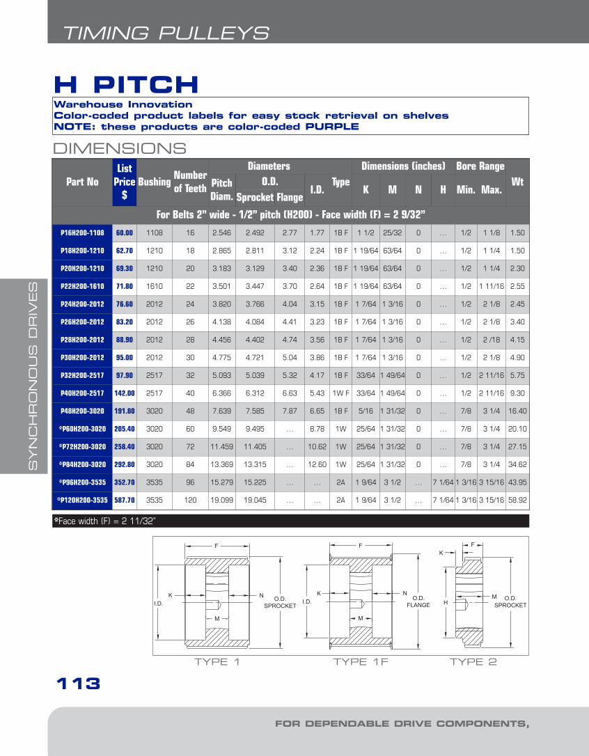
SYN
CH
RO
NO
US
DR
IVES
113
TIMING PULLEYS
FOR DEPENDABLE DRIVE COMPONENTS, BE SURE TO SPECIFY
H PITCH
DIMENSIONS
Part NoList
Price$
BushingNumberof Teeth
DiametersType
Dimensions (inches) Bore RangeWtPitch
Diam.O.D.
I.D. K M N H Min. Max.Sprocket Flange
For Belts 2” wide - 1/2” pitch (H200) - Face width (F) = 2 9/32”
P16H200-1108 60.00 1108 16 2.546 2.492 2.77 1.77 1B F 1 1/2 25/32 0 … 1/2 1 1/8 1.50
P18H200-1210 62.70 1210 18 2.865 2.811 3.12 2.24 1B F 1 19/64 63/64 0 … 1/2 1 1/4 1.50
P20H200-1210 69.30 1210 20 3.183 3.129 3.40 2.36 1B F 1 19/64 63/64 0 … 1/2 1 1/4 2.30
P22H200-1610 71.80 1610 22 3.501 3.447 3.70 2.64 1B F 1 19/64 63/64 0 … 1/2 1 11/16 2.55
P24H200-2012 76.60 2012 24 3.820 3.766 4.04 3.15 1B F 1 7/64 1 3/16 0 … 1/2 2 1/8 2.45
P26H200-2012 83.20 2012 26 4.138 4.084 4.41 3.23 1B F 1 7/64 1 3/16 0 … 1/2 2 1/8 3.40
P28H200-2012 88.90 2012 28 4.456 4.402 4.74 3.56 1B F 1 7/64 1 3/16 0 … 1/2 2 /18 4.15
P30H200-2012 95.00 2012 30 4.775 4.721 5.04 3.86 1B F 1 7/64 1 3/16 0 … 1/2 2 1/8 4.90
P32H200-2517 97.90 2517 32 5.093 5.039 5.32 4.17 1B F 33/64 1 49/64 0 … 1/2 2 11/16 5.75
P40H200-2517 142.00 2517 40 6.366 6.312 6.63 5.43 1W F 33/64 1 49/64 0 … 1/2 2 11/16 9.30
P48H200-3020 191.80 3020 48 7.639 7.585 7.87 6.65 1B F 5/16 1 31/32 0 … 7/8 3 1/4 16.40
*P60H200-3020 205.40 3020 60 9.549 9.495 … 8.78 1W 25/64 1 31/32 0 … 7/8 3 1/4 20.10
*P72H200-3020 258.40 3020 72 11.459 11.405 … 10.62 1W 25/64 1 31/32 0 … 7/8 3 1/4 27.15
*P84H200-3020 292.80 3020 84 13.369 13.315 … 12.60 1W 25/64 1 31/32 0 … 7/8 3 1/4 34.62
*P96H200-3535 352.70 3535 96 15.279 15.225 … … 2A 1 9/64 3 1/2 … 7 1/64 1 3/16 3 15/16 43.95
*P120H200-3535 587.70 3535 120 19.099 19.045 … … 2A 1 9/64 3 1/2 … 7 1/64 1 3/16 3 15/16 58.92
*Face width (F) = 2 11/32”
Warehouse InnovationColor-coded product labels for easy stock retrieval on shelvesNOTE: these products are color-coded PURPLE
TYPE 1F TYPE 2
I.D.
M
NH
M O.D.SPROCKETI.D.
M
N O.D.SPROCKET
TYPE 1
5-Synchronous1.8.qxp 2009-03-19 14:08 Page 10

SYN
CH
RO
NO
US
DR
IVES
114
TIMING PULLEYS
BE SURE TO SPECIFY
DIMENSIONS
Part NoList
Price$
BushingNumberof Teeth
DiametersType
Dimensions (inches) Bore RangeWtPitch
Diam.O.D.
I.D. K M N H Min. Max.Sprocket Flange
For Belts 3” wide - 1/2” pitch (H300) - Face width (F) = 3 5/16”P16H300-1108 79.70 1108 16 2.546 2.492 2.77 1.82 1B F 1 17/64 25/32 1 17/64 … 1/2 1 1/8 2.00
P18H300-1210 88.60 1210 18 2.865 2.811 3.12 2.24 1B F 1 5/32 63/64 1 5/32 … 1/2 1 1/4 2.05
P20H300-1210 107.70 1210 20 3.183 3.129 3.40 2.36 1B F 1 5/32 63/64 1 5/32 … 1/2 1 1/4 3.05
P22H300-1610 106.80 1610 22 3.501 3.447 3.70 2.64 1B F 1 5/32 63/64 1 5/32 … 1/2 1 11/16 3.50
P24H300-2012 114.30 2012 24 3.820 3.766 4.04 2.95 1B F 1 1/16 1 3/16 1 1/16 … 1/2 2 1/8 4.05
P26H300-2012 120.70 2012 26 4.138 4.084 4.41 3.23 1B F 1 1/16 1 3/16 1 1/16 … 1/2 2 1/8 4.60
P28H300-2012 127.30 2012 28 4.456 4.402 4.74 3.56 1B F 1 1/16 1 3/16 1 1/16 … 1/2 2 1/8 5.40
P30H300-2012 140.50 2012 30 4.775 4.721 5.04 3.86 1B F 1 1/16 1 3/16 1 1/16 … 1/2 2 1/8 6.45
P32H300-2517 148.80 2517 32 5.093 5.039 5.32 4.17 1B F 49/64 1 49/64 49/64 … 1/2 2 11/16 7.25
P40H300-2517 184.20 2517 40 6.366 6.312 6.63 5.43 1W F 1 17/32 1 49/64 0 … 1/2 2 11/16 11.40
**P48H300-3020 254.90 3020 48 7.639 7.585 7.87 6.65 1B F 1 27/64 1 31/32 0 … 7/8 3 1/4 19.25
**P60H300-3020 254.50 3020 60 9.549 9.495 … 8.78 1W 1 27/64 1 31/32 0 … 7/8 3 1/4 22.60
**P72H300-3020 332.00 3020 72 11.459 11.405 … 10.62 1W 1 27/64 1 31/32 0 … 7/8 3 1/4 30.70
**P84H300-3020 412.60 3020 84 13.369 13.315 … 12.60 1W 1 27/64 1 31/32 0 … 7/8 3 1/4 37.45
**P96H300-3535 494.20 3535 96 15.279 15.225 … … 2A 1/8 3 1/2 ... 7 1/64 1 3/16 3 15/16 51.84
**P120H300-3535 704.80 3535 120 19.099 19.045 … … 2A 1/8 3 1/2 ... 7 1/64 1 3/16 3 15/16 75.08
** Face width (F) = 3 3/8”
Warehouse InnovationColor-coded product labels for easy stock retrieval on shelvesNOTE: these products are color-coded PURPLE
TYPE 1F TYPE 2
I.D.
M
NH
M O.D.SPROCKETI.D.
M
N O.D.SPROCKET
TYPE 1
H PITCH
5-Synchronous1.8.qxp 2009-03-19 14:08 Page 11

SYN
CH
RO
NO
US
DR
IVES
115
HTD SPROCKETS
FOR DEPENDABLE DRIVE COMPONENTS, BE SURE TO SPECIFY
EXAMPLE: P64-8M-50-SKP64 8M
P64: NUMBER OF TEETH (64)8M: TOOTH PITCH (8mm)50: HIGH TORQUE BELT WIDTH (50mm)SK: HUB SIZE RELATED TO QD BUSHING
HOW TO ORDER
50 SK
HTD SPROCKET
• All parts are completely machined in cast iron;some parts made from steel
• Positive, non-slip drive• No lubrication necessary, non-stretch• Smooth operation: no chain drive that results in
vibration and speed variation• Clean operation, long-life expectancy, low
maintenance• Quiet; no metal-to-metal contact
DID YOU KNOW THAT...
HTD synchronous belt drives combine the positive timing action of gears with the flexibility, speed and low noise level of belts. Maska HTD sprockets are manufactured in various sizes, dimensions andcapacities to meet industry requirements -- fromspeeds as low as 10 RPM to speeds over 5,000 RPMand horsepower ratings from fractional to more than250 HP.
• Maska does not recommend usingHTD sprockets with QD bushings thatdo not have a keyseat.
• The synchronous sprockets detailed in thefollowing tables are all stock sizes. Alldimensions include the sprocket with the QDbushing in place and are in inches.
IMPORTANT REMINDER
1. All Charts: The type of sheave construction isindicated in the column entitled « T ». The numberrefers to the drawing and the letter as follows: A =arms; B = block; W = web; F = flanges
2. All dimensions are to the closest fraction.
3. Weight for all items is approximate.
5-Synchronous1.8.qxp 2009-03-19 14:08 Page 12
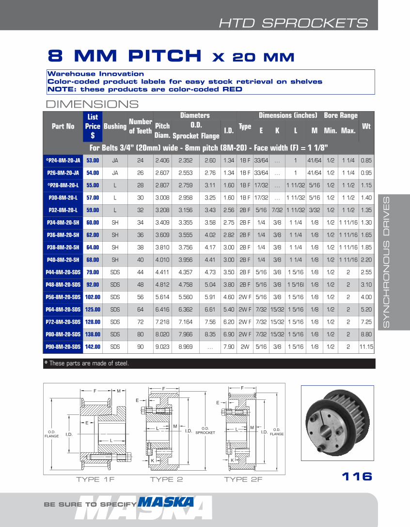
SYN
CH
RO
NO
US
DR
IVES
116
8 MM PITCH X 20 MM
DIMENSIONS
Part NoList
Price$
BushingNumberof Teeth
DiametersType
Dimensions (inches) Bore RangeWtPitch
Diam.O.D.
I.D. E K L M Min. Max.Sprocket Flange
For Belts 3/4” (20mm) wide - 8mm pitch (8M-20) - Face width (F) = 1 1/8” *P24-8M-20-JA 53.00 JA 24 2.406 2.352 2.60 1.34 1B F 33/64 … 1 41/64 1/2 1 1/4 0.85
P26-8M-20-JA 54.00 JA 26 2.607 2.553 2.76 1.34 1B F 33/64 … 1 41/64 1/2 1 1/4 0.95
*P28-8M-20-L 55.00 L 28 2.807 2.759 3.11 1.60 1B F 17/32 … 1 11/32 5/16 1/2 1 1/2 1.15
P30-8M-20-L 57.00 L 30 3.008 2.958 3.25 1.60 1B F 17/32 … 1 11/32 5/16 1/2 1 1/2 1.40
P32-8M-20-L 59.00 L 32 3.208 3.156 3.43 2.56 2B F 5/16 7/32 1 11/32 3/32 1/2 1 1/2 1.35
P34-8M-20-SH 60.00 SH 34 3.409 3.355 3.58 2.75 2B F 1/4 3/8 1 1/4 1/8 1/2 1 11/16 1.30
P36-8M-20-SH 62.00 SH 36 3.609 3.555 4.02 2.82 2B F 1/4 3/8 1 1/4 1/8 1/2 1 11/16 1.65
P38-8M-20-SH 64.00 SH 38 3.810 3.756 4.17 3.00 2B F 1/4 3/8 1 1/4 1/8 1/2 1 11/16 1.85
P40-8M-20-SH 68.00 SH 40 4.010 3.956 4.41 3.00 2B F 1/4 3/8 1 1/4 1/8 1/2 1 11/16 2.20
P44-8M-20-SDS 79.00 SDS 44 4.411 4.357 4.73 3.50 2B F 5/16 3/8 1 5/16 1/8 1/2 2 2.55
P48-8M-20-SDS 92.00 SDS 48 4.812 4.758 5.04 3.80 2B F 5/16 3/8 1 5/16| 1/8 1/2 2 3.10
P56-8M-20-SDS 102.00 SDS 56 5.614 5.560 5.91 4.60 2W F 5/16 3/8 1 5/16 1/8 1/2 2 4.00
P64-8M-20-SDS 125.00 SDS 64 6.416 6.362 6.61 5.40 2W F 7/32 15/32 1 5/16 1/8 1/2 2 5.20
P72-8M-20-SDS 128.00 SDS 72 7.218 7.164 7.56 6.20 2W F 7/32 15/32 1 5/16 1/8 1/2 2 7.25
P80-8M-20-SDS 138.00 SDS 80 8.020 7.966 8.35 6.90 2W F 7/32 15/32 1 5/16 1/8 1/2 2 8.80
P90-8M-20-SDS 142.00 SDS 90 9.023 8.969 … 7.90 2W 5/16 3/8 1 5/16 1/8 1/2 2 11.15
Warehouse InnovationColor-coded product labels for easy stock retrieval on shelvesNOTE: these products are color-coded RED
* These parts are made of steel.
TYPE 2 TYPE 2F
I.D. O.D.SPROCKET
ML
K
E
I.D.
K
E
O.D.FLANGE
L M
M
E
L
O.D.FLANGE I.D.
TYPE 1F
HTD SPROCKETS
BE SURE TO SPECIFY
5-Synchronous1.8.qxp 2009-03-19 14:08 Page 13

SYN
CH
RO
NO
US
DR
IVES
117
HTD SPROCKETS
FOR DEPENDABLE DRIVE COMPONENTS, BE SURE TO SPECIFY
8 MM PITCH X 30 MM
DIMENSIONS
Part NoList
Price$
BushingNumberof Teeth
DiametersType
Dimensions (inches) Bore RangeWtPitch
Diam.O.D.
I.D. E K L M Min. Max.Sprocket Flange
For Belts 1 3/16” (30mm) wide - 8mm pitch (8M-30) - Face width (F) = 1 1/2”*P24-8M-30-JA 54.00 JA 24 2.406 2.352 2.60 1.34 1B F 33/64 … 1 1 1/64 1/2 1 1/4 1.15
P26-8M-30-JA 56.00 JA 26 2.607 2.553 2.76 1.34 1B F 33/64 … 1 1 1/64 1/2 1 1/4 1.25
*P28-8M-30-L 59.00 L 28 2.807 2.759 3.11 1.60 1B F 17/32 … 1 11/32 11/16 1/2 1 1/2 1.40
P30-8M-30-L 60.00 L 30 3.008 2.958 3.25 1.60 1B F 17/32 … 1 11/32 11/16 1/2 1 1/2 1.70
P32-8M-30-L 62.00 L 32 3.208 3.156 3.43 2.56 3B F 1/16 19/32 1 11/32 3/32 1/2 1 1/2 1.60
P34-8M-30-SH 63.00 SH 34 3.409 3.355 3.58 2.75 3B F 1/8 3/4 1 1/4 1/8 1/2 1 11/16 1.55
P36-8M-30-SH 68.00 SH 36 3.609 3.555 4.02 2.82 3B F 1/8 3/4 1 1/4 1/8 1/2 1 11/16 2.00
P38-8M-30-SH 70.00 SH 38 3.810 3.756 4.17 3.00 3B F 1/8 3/4 1 1/4 1/8 1/2 1 11/16 2.15
P40-8M-30-SH 78.00 SH 40 4.010 3.956 4.41 3.00 3B F 1/8 3/4 1 1/4 1/8 1/2 1 11/16 2.65
P44-8M-30-SDS 86.00 SDS 44 4.411 4.357 4.73 3.50 3B F 1/16 3/4 1 5/16 1/8 1/2 2 2.90
P48-8M-30-SDS 93.00 SDS 48 4.812 4.758 5.04 3.80 3B F 1/16 3/4 1 5/16 1/8 1/2 2 3.55
P56-8M-30-SDS 104.00 SDS 56 5.614 5.560 5.91 4.60 3W F 1/16 3/4 1 5/16 1/8 1/2 2 4.65
P64-8M-30-SK 126.00 SK 64 6.416 6.362 6.61 5.40 2B F 15/32 11/32 1 7/8 3/16 1/2 2 5/8 8.45
P72-8M-30-SK 138.00 SK 72 7.218 7.164 7.56 6.20 2W F 15/32 11/32 1 7/8 3/16 1/2 2 5/8 8.75
P80-8M-30-SK 142.00 SK 80 8.020 7.966 8.35 6.90 2W F 15/32 11/32 1 7/8 3/16 1/2 2 5/8 10.80
P90-8M-30-SK 146.00 SK 90 9.023 8.969 … 7.90 2W 9/16 1/4 1 7/8 3/16 1/2 2 5/8 13.00
P112-8M-30-SK 186.00 SK 112 11.229 11.175 … 10.00 2A 9/16 1/4 1 7/8 3/16 1/2 2 5/8 14.25
Warehouse InnovationColor-coded product labels for easy stock retrieval on shelvesNOTE: these products are color-coded RED
TYPE 2 TYPE 2F
I.D. O.D.SPROCKET
ML
K
E
I.D.
K
E
O.D.FLANGE
L M
M
E
L
O.D.FLANGE I.D.
TYPE 1F TYPE 3F
O.D.FLANGE
I.D.
M
E
K
L
* These parts are made of steel.
5-Synchronous1.8.qxp 2009-03-19 14:08 Page 14

SYN
CH
RO
NO
US
DR
IVES
118
HTD SPROCKETS
BE SURE TO SPECIFY
DIMENSIONS
Part NoList
Price$
BushingNumberof Teeth
DiametersType
Dimensions (inches) Bore RangeWtPitch
Diam.O.D.
I.D. E K L M Min. Max.Sprocket Flange
For Belts 2” (50mm) wide - 8mm pitch (8M-50) - Face width (F) = 2 3/8” P28-8M-50-JA 80.00 JA 28 2.807 2.759 3.11 2.09 3B F 31/64 1 1 57/64 1/2 1 1/4 1.60
P30-8M-50-JA 82.00 JA 30 3.008 2.958 3.25 2.18 3B F 31/64 1 1 57/64 1/2 1 1/4 1.95
P32-8M-50-L 83.00 L 32 3.208 3.156 3.43 2.56 3B F 11/32 7/8 1 11/32 11/16 1/2 1 1/2 2.05
P34-8M-50-SH 84.00 SH 34 3.409 3.355 3.58 2.75 2B F 1/8 1/2 1 1/4 1 1/4 1/2 1 11/16 2.00
P36-8M-50-SH 85.00 SH 36 3.609 3.555 4.02 2.82 2B F 1/8 1/2 1 1/4 1 1/4 1/2 1 11/16 2.65
P38-8M-50-SH 86.00 SH 38 3.810 3.756 4.17 3.00 2B F 1/8 1/2 1 1/4 1 1/4 1/2 1 11/16 2.85
P40-8M-50-SH 88.00 SH 40 4.010 3.956 4.41 3.00 2B F 1/8 1/2 1 1/4 1 1/4 1/2 1 11/16 3.60
P44-8M-50-SD 94.00 SD 44 4.411 4.357 4.73 3.50 2B F 1/8 9/16 1 13/16 11/16 1/2 2 4.55
P48-8M-50-SD 98.00 SD 48 4.812 4.758 5.04 3.80 2B F 1/8 9/16 1 13/16 11/16 1/2 2 5.80
P56-8M-50-SK 115.00 SK 56 5.614 5.560 5.91 4.60 2B F 1/4 9/16 1 7/8 3/4 1/2 2 5/8 7.30
P64-8M-50-SK 130.00 SK 64 6.416 6.362 6.61 5.40 2W F 13/64 39/64 1 7/8 51/64 1/2 2 5/8 8.60
P72-8M-50-SK 144.00 SK 72 7.218 7.164 7.56 6.20 2W F 13/64 39/64 1 7/8 51/64 1/2 2 5/8 10.70
P80-8M-50-SF 155.00 SF 80 8.020 7.966 8.35 6.90 2W F 13/64 39/64 2 43/64 1/2 2 15/16 14.15
P90-8M-50-SF 186.00 SF 90 9.023 8.969 … 7.90 2W 1/4 9/16 2 5/8 1/2 2 15/16 16.70
P112-8M-50-SF 234.00 SF 112 11.229 11.175 … 10.00 2A 1/4 9/16 2 5/8 1/2 2 15/16 21.65
P144-8M-50-E 373.00 E 144 14.437 14.383 … 13.20 2A 11/16 3/8 2 5/8 7/16 7/8 3 1/2 31.75
P192-8M-50-E 432.00 E 192 19.249 19.195 … 18.00 2A 11/16 3/8 2 5/8 7/16 7/8 3 1/2 50.80
Warehouse InnovationColor-coded product labels for easy stock retrieval on shelvesNOTE: these products are color-coded RED
TYPE 2F TYPE 3F
I.D.
K
E
O.D.FLANGE
L MI.D. O.D.
SPROCKET
ML
K
E
TYPE 2
8 MM PITCH X 50 MM
5-Synchronous1.8.qxp 2009-03-19 14:08 Page 15
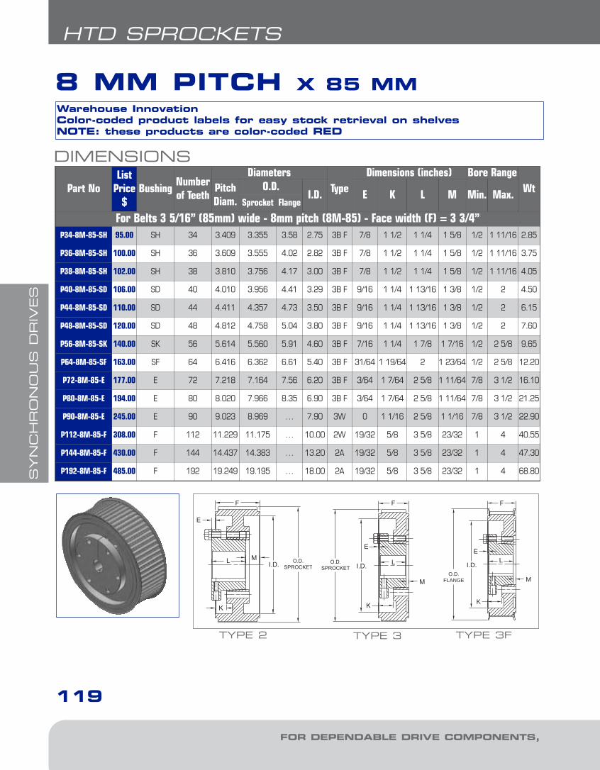
SYN
CH
RO
NO
US
DR
IVES
119
HTD SPROCKETS
FOR DEPENDABLE DRIVE COMPONENTS, BE SURE TO SPECIFY
8 MM PITCH X 85 MM
DIMENSIONS
Part NoList
Price$
BushingNumberof Teeth
DiametersType
Dimensions (inches) Bore RangeWtPitch
Diam.O.D.
I.D. E K L M Min. Max.Sprocket Flange
For Belts 3 5/16” (85mm) wide - 8mm pitch (8M-85) - Face width (F) = 3 3/4” P34-8M-85-SH 95.00 SH 34 3.409 3.355 3.58 2.75 3B F 7/8 1 1/2 1 1/4 1 5/8 1/2 1 11/16 2.85
P36-8M-85-SH 100.00 SH 36 3.609 3.555 4.02 2.82 3B F 7/8 1 1/2 1 1/4 1 5/8 1/2 1 11/16 3.75
P38-8M-85-SH 102.00 SH 38 3.810 3.756 4.17 3.00 3B F 7/8 1 1/2 1 1/4 1 5/8 1/2 1 11/16 4.05
P40-8M-85-SD 106.00 SD 40 4.010 3.956 4.41 3.29 3B F 9/16 1 1/4 1 13/16 1 3/8 1/2 2 4.50
P44-8M-85-SD 110.00 SD 44 4.411 4.357 4.73 3.50 3B F 9/16 1 1/4 1 13/16 1 3/8 1/2 2 6.15
P48-8M-85-SD 120.00 SD 48 4.812 4.758 5.04 3.80 3B F 9/16 1 1/4 1 13/16 1 3/8 1/2 2 7.60
P56-8M-85-SK 140.00 SK 56 5.614 5.560 5.91 4.60 3B F 7/16 1 1/4 1 7/8 1 7/16 1/2 2 5/8 9.65
P64-8M-85-SF 163.00 SF 64 6.416 6.362 6.61 5.40 3B F 31/64 1 19/64 2 1 23/64 1/2 2 5/8 12.20
P72-8M-85-E 177.00 E 72 7.218 7.164 7.56 6.20 3B F 3/64 1 7/64 2 5/8 1 11/64 7/8 3 1/2 16.10
P80-8M-85-E 194.00 E 80 8.020 7.966 8.35 6.90 3B F 3/64 1 7/64 2 5/8 1 11/64 7/8 3 1/2 21.25
P90-8M-85-E 245.00 E 90 9.023 8.969 … 7.90 3W 0 1 1/16 2 5/8 1 1/16 7/8 3 1/2 22.90
P112-8M-85-F 308.00 F 112 11.229 11.175 … 10.00 2W 19/32 5/8 3 5/8 23/32 1 4 40.55
P144-8M-85-F 430.00 F 144 14.437 14.383 … 13.20 2A 19/32 5/8 3 5/8 23/32 1 4 47.30
P192-8M-85-F 485.00 F 192 19.249 19.195 … 18.00 2A 19/32 5/8 3 5/8 23/32 1 4 68.80
Warehouse InnovationColor-coded product labels for easy stock retrieval on shelvesNOTE: these products are color-coded RED
TYPE 3 TYPE 3F
O.D.SPROCKET I.D.
M
E
K
L
O.D.FLANGE
I.D.
M
E
K
LI.D. O.D.SPROCKET
ML
K
E
TYPE 2
5-Synchronous1.8.qxp 2009-03-19 14:08 Page 16

SYN
CH
RO
NO
US
DR
IVES
120
HTD SPROCKETS
BE SURE TO SPECIFY
DIMENSIONS
Part NoList
Price$
BushingNb.
Teeth
DiametersType
Dimensions (inches) Bore RangeWtPitch
Diam.O.D.
I.D. E K L M Min. Max.Sprocket Flange
For Belts 2” (40mm) wide - 14mm pitch (14M-40) - Face width (F) = 2 1/8” P28-14M-40-SK 85.00 SK 28 4.912 4.802 5.04 3.13 1B F 13/16 0 1 7/8 1 1/16 1/2 2 5/8 5.30
P29-14M-40-SK 90.00 SK 29 5.088 4.978 5.43 3.13 1B F 13/16 0 1 7/8 1 1/16 1/2 2 5/8 6.00
P30-14M-40-SK 93.00 SK 30 5.263 5.153 5.43 4.12 2B F 3/8 7/16 1 7/8 5/8 1/2 2 5/8 5.85
P32-14M-40-SK 102.00 SK 32 5.614 5.504 6.06 4.12 2B F 3/8 7/16 1 7/8 5/8 1/2 2 5/8 7.10
P34-14M-40-SK 105.00 SK 34 5.965 5.855 6.30 4.12 2B F 3/8 7/16 1 7/8 5/8 1/2 2 5/8 8.55
P36-14M-40-SF 115.00 SF 36 6.316 6.206 6.61 4.75 2B F 3/8 7/16 2 1/2 1/2 2 15/16 8.50
P38-14M-40-SF 130.00 SF 38 6.667 6.557 7.21 4.94 2B F 3/8 7/16 2 1/2 1/2 2 15/16 10.20
P40-14M-40-SF 130.00 SF 40 7.018 6.908 7.40 5.06 2B F 3/8 7/16 2 1/2 1/2 2 15/16 11.75
P44-14M-40-E 155.00 E 44 7.720 7.610 8.31 6.12 2B F 13/16 1/4 2 5/8 5/16 7/8 3 1/2 14.80
P48-14M-40-E 165.00 E 48 8.421 8.311 8.90 6.50 2B F 13/16 1/4 2 5/8 5/16 7/8 3 1/2 18.65
P52-14M-40-E 172.00 E 52 9.123 9.013 9.37 7.18 2B F 13/16 1/4 2 5/8 5/16 7/8 3 1/2 22.70
P56-14M-40-E 175.00 E 56 9.825 9.715 10.08 7.88 2B F 13/16 1/4 2 5/8 5/16 7/8 3 1/2 27.25
P60-14M-40-E 227.00 E 60 10.527 10.417 10.79 8.50 2B F 13/16 1/4 2 5/8 5/16 7/8 3 1/2 32.10
P64-14M-40-E 260.00 E 64 11.229 11.119 11.65 9.25 2W F 13/16 1/4 2 5/8 5/16 7/8 3 1/2 29.20
P68-14M-40-E 265.00 E 68 11.930 11.820 12.21 10.00 2W F 13/16 1/4 2 5/8 5/16 7/8 3 1/2 31.55
P72-14M-40-E 272.00 E 72 12.632 12.522 12.91 10.69 2W F 13/16 1/4 2 5/8 5/16 7/8 3 1/2 35.25
P80-14M-40-E 280.00 E 80 14.036 13.926 14.29 12.13 2W F 13/16 1/4 2 5/8 5/16 7/8 3 1/2 14.40
P90-14M-40-E 288.00 E 90 15.790 15.680 … 14.00 2A 13/16 1/4 2 5/8 5/16 7/8 3 1/2 40.70
P112-14M-40-E 365.00 E 112 19.650 19.540 … 17.80 2A 13/16 1/4 2 5/8 5/16 7/8 3 1/2 56.40
P144-14M-40-E 480.00 E 144 25.264 25.154 … 23.38 2A 13/16 1/4 2 5/8 5/16 7/8 3 1/2 78.60
14 MM PITCH X 40 MMWarehouse InnovationColor-coded product labels for easy stock retrieval on shelvesNOTE: these products are color-coded GREEN
TYPE 2 TYPE 2F
I.D. O.D.SPROCKET
ML
K
E
I.D.
K
E
O.D.FLANGE
L M
M
E
L
O.D.FLANGE I.D.
TYPE 1F
5-Synchronous1.8.qxp 2009-03-19 14:08 Page 17
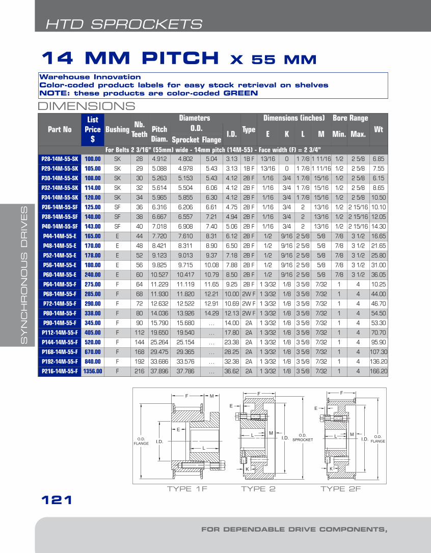
SYN
CH
RO
NO
US
DR
IVES
121
HTD SPROCKETS
FOR DEPENDABLE DRIVE COMPONENTS, BE SURE TO SPECIFY
14 MM PITCH X 55 MM
DIMENSIONS
Part NoList
Price$
BushingNb.
Teeth
DiametersType
Dimensions (inches) Bore RangeWtPitch
Diam.O.D.
I.D. E K L M Min. Max.Sprocket Flange
For Belts 2 3/16” (55mm) wide - 14mm pitch (14M-55) - Face width (F) = 2 3/4”P28-14M-55-SK 100.00 SK 28 4.912 4.802 5.04 3.13 1B F 13/16 0 1 7/8 1 11/16 1/2 2 5/8 6.85
P29-14M-55-SK 105.00 SK 29 5.088 4.978 5.43 3.13 1B F 13/16 0 1 7/8 1 11/16 1/2 2 5/8 7.55
P30-14M-55-SK 108.00 SK 30 5.263 5.153 5.43 4.12 2B F 1/16 3/4 1 7/8 15/16 1/2 2 5/8 6.15
P32-14M-55-SK 114.00 SK 32 5.614 5.504 6.06 4.12 2B F 1/16 3/4 1 7/8 15/16 1/2 2 5/8 8.65
P34-14M-55-SK 120.00 SK 34 5.965 5.855 6.30 4.12 2B F 1/16 3/4 1 7/8 15/16 1/2 2 5/8 10.50
P36-14M-55-SF 125.00 SF 36 6.316 6.206 6.61 4.75 2B F 1/16 3/4 2 13/16 1/2 2 15/16 10.10
P38-14M-55-SF 140.00 SF 38 6.667 6.557 7.21 4.94 2B F 1/16 3/4 2 13/16 1/2 2 15/16 12.05
P40-14M-55-SF 143.00 SF 40 7.018 6.908 7.40 5.06 2B F 1/16 3/4 2 13/16 1/2 2 15/16 14.30
P44-14M-55-E 165.00 E 44 7.720 7.610 8.31 6.12 2B F 1/2 9/16 2 5/8 5/8 7/8 3 1/2 16.65
P48-14M-55-E 170.00 E 48 8.421 8.311 8.90 6.50 2B F 1/2 9/16 2 5/8 5/8 7/8 3 1/2 21.65
P52-14M-55-E 178.00 E 52 9.123 9.013 9.37 7.18 2B F 1/2 9/16 2 5/8 5/8 7/8 3 1/2 25.80
P56-14M-55-E 180.00 E 56 9.825 9.715 10.08 7.88 2B F 1/2 9/16 2 5/8 5/8 7/8 3 1/2 31.00
P60-14M-55-E 240.00 E 60 10.527 10.417 10.79 8.50 2B F 1/2 9/16 2 5/8 5/8 7/8 3 1/2 36.05
P64-14M-55-F 275.00 F 64 11.229 11.119 11.65 9.25 2B F 1 3/32 1/8 3 5/8 7/32 1 4 10.25
P68-14M-55-F 285.00 F 68 11.930 11.820 12.21 10.00 2W F 1 3/32 1/8 3 5/8 7/32 1 4 44.00
P72-14M-55-F 290.00 F 72 12.632 12.522 12.91 10.69 2W F 1 3/32 1/8 3 5/8 7/32 1 4 46.70
P80-14M-55-F 338.00 F 80 14.036 13.926 14.29 12.13 2W F 1 3/32 1/8 3 5/8 7/32 1 4 54.50
P90-14M-55-F 345.00 F 90 15.790 15.680 … 14.00 2A 1 3/32 1/8 3 5/8 7/32 1 4 53.30
P112-14M-55-F 405.00 F 112 19.650 19.540 … 17.80 2A 1 3/32 1/8 3 5/8 7/32 1 4 70.70
P144-14M-55-F 520.00 F 144 25.264 25.154 … 23.38 2A 1 3/32 1/8 3 5/8 7/32 1 4 95.90
P168-14M-55-F 670.00 F 168 29.475 29.365 … 28.25 2A 1 3/32 1/8 3 5/8 7/32 1 4 107.30
P192-14M-55-F 840.00 F 192 33.686 33.576 … 32.38 2A 1 3/32 1/8 3 5/8 7/32 1 4 136.20
P216-14M-55-F 1356.00 F 216 37.896 37.786 … 36.62 2A 1 3/32 1/8 3 5/8 7/32 1 4 166.20
Warehouse InnovationColor-coded product labels for easy stock retrieval on shelvesNOTE: these products are color-coded GREEN
TYPE 2 TYPE 2F
I.D. O.D.SPROCKET
ML
K
E
I.D.
K
E
O.D.FLANGE
L M
M
E
L
O.D.FLANGE I.D.
TYPE 1F
5-Synchronous1.8.qxp 2009-03-19 14:08 Page 18
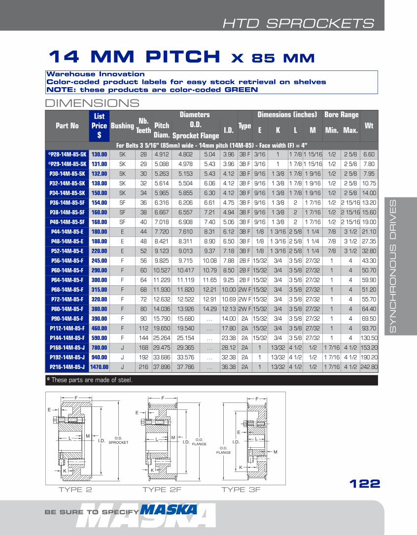
SYN
CH
RO
NO
US
DR
IVES
122
HTD SPROCKETS
BE SURE TO SPECIFY
DIMENSIONS
Part NoList
Price$
BushingNb.
Teeth
DiametersType
Dimensions (inches) Bore RangeWtPitch
Diam.O.D.
I.D. E K L M Min. Max.Sprocket Flange
For Belts 3 5/16” (85mm) wide - 14mm pitch (14M-85) - Face width (F) = 4”*P28-14M-85-SK 130.00 SK 28 4.912 4.802 5.04 3.96 3B F 3/16 1 1 7/8 1 15/16 1/2 2 5/8 6.60
*P29-14M-85-SK 131.00 SK 29 5.088 4.978 5.43 3.96 3B F 3/16 1 1 7/8 1 15/16 1/2 2 5/8 7.80
P30-14M-85-SK 132.00 SK 30 5.263 5.153 5.43 4.12 3B F 9/16 1 3/8 1 7/8 1 9/16 1/2 2 5/8 7.95
P32-14M-85-SK 138.00 SK 32 5.614 5.504 6.06 4.12 3B F 9/16 1 3/8 1 7/8 1 9/16 1/2 2 5/8 10.75
P34-14M-85-SK 150.00 SK 34 5.965 5.855 6.30 4.12 3B F 9/16 1 3/8 1 7/8 1 9/16 1/2 2 5/8 14.00
P36-14M-85-SF 154.00 SF 36 6.316 6.206 6.61 4.75 3B F 9/16 1 3/8 2 1 7/16 1/2 2 15/16 13.20
P38-14M-85-SF 160.00 SF 38 6.667 6.557 7.21 4.94 3B F 9/16 1 3/8 2 1 7/16 1/2 2 15/16 15.60
P40-14M-85-SF 168.00 SF 40 7.018 6.908 7.40 5.06 3B F 9/16 1 3/8 2 1 7/16 1/2 2 15/16 19.00
P44-14M-85-E 180.00 E 44 7.720 7.610 8.31 6.12 3B F 1/8 1 3/16 2 5/8 1 1/4 7/8 3 1/2 21.10
P48-14M-85-E 188.00 E 48 8.421 8.311 8.90 6.50 3B F 1/8 1 3/16 2 5/8 1 1/4 7/8 3 1/2 27.35
P52-14M-85-E 220.00 E 52 9.123 9.013 9.37 7.18 3B F 1/8 1 3/16 2 5/8 1 1/4 7/8 3 1/2 32.80
P56-14M-85-F 245.00 F 56 9.825 9.715 10.08 7.88 2B F 15/32 3/4 3 5/8 27/32 1 4 43.30
P60-14M-85-F 290.00 F 60 10.527 10.417 10.79 8.50 2B F 15/32 3/4 3 5/8 27/32 1 4 50.70
P64-14M-85-F 300.00 F 64 11.229 11.119 11.65 9.25 2B F 15/32 3/4 3 5/8 27/32 1 4 59.90
P68-14M-85-F 315.00 F 68 11.930 11.820 12.21 10.00 2W F 15/32 3/4 3 5/8 27/32 1 4 51.20
P72-14M-85-F 320.00 F 72 12.632 12.522 12.91 10.69 2W F 15/32 3/4 3 5/8 27/32 1 4 55.70
P80-14M-85-F 380.00 F 80 14.036 13.926 14.29 12.13 2W F 15/32 3/4 3 5/8 27/32 1 4 64.40
P90-14M-85-F 390.00 F 90 15.790 15.680 … 14.00 2A 15/32 3/4 3 5/8 27/32 1 4 69.50
P112-14M-85-F 460.00 F 112 19.650 19.540 … 17.80 2A 15/32 3/4 3 5/8 27/32 1 4 93.70
P144-14M-85-F 590.00 F 144 25.264 25.154 … 23.38 2A 15/32 3/4 3 5/8 27/32 1 4 130.50
P168-14M-85-J 780.00 J 168 29.475 29.365 … 28.12 2A 1 13/32 4 1/2 1/2 1 7/16 4 1/2 153.20
P192-14M-85-J 940.00 J 192 33.686 33.576 … 32.38 2A 1 13/32 4 1/2 1/2 1 7/16 4 1/2 190.20
P216-14M-85-J 1470.00 J 216 37.896 37.786 … 36.38 2A 1 13/32 4 1/2 1/2 1 7/16 4 1/2 242.80
* These parts are made of steel.
14 MM PITCH X 85 MMWarehouse InnovationColor-coded product labels for easy stock retrieval on shelvesNOTE: these products are color-coded GREEN
TYPE 2F TYPE 3F
I.D.
K
E
O.D.FLANGE
L M
O.D.FLANGE
I.D.
M
E
K
LI.D. O.D.SPROCKET
ML
K
E
TYPE 2
5-Synchronous1.8.qxp 2009-03-19 14:08 Page 19
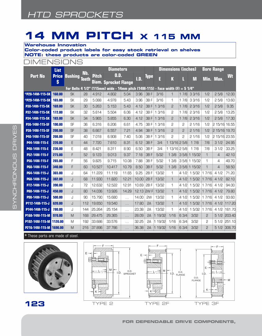
SYN
CH
RO
NO
US
DR
IVES
123
HTD SPROCKETS
FOR DEPENDABLE DRIVE COMPONENTS, BE SURE TO SPECIFY
DIMENSIONS
Part NoList
Price$
BushingNb.
Teeth
DiametersType
Dimensions (inches) Bore RangeWtPitch
Diam.O.D.
I.D. E K L M Min. Max.Sprocket Flange
For Belts 4 1/2” (115mm) wide - 14mm pitch (14M-115) - Face width (F) = 5 1/4”*P28-14M-115-SK 160.00 SK 28 4.912 4.802 5.04 3.96 3B F 3/16 1 1 7/8 3 3/16 1/2 2 5/8 12.00
*P29-14M-115-SK 165.00 SK 29 5.088 4.978 5.43 3.96 3B F 3/16 1 1 7/8 3 3/16 1/2 2 5/8 13.60
P30-14M-115-SK 169.00 SK 30 5.263 5.153 5.43 4.12 3B F 1 3/16 2 1 7/8 2 3/16 1/2 2 5/8 9.35
P32-14M-115-SK 172.00 SK 32 5.614 5.504 6.06 4.12 3B F 1 3/16 2 1 7/8 2 3/16 1/2 2 5/8 13.25
P34-14M-115-SK 183.00 SK 34 5.965 5.855 6.30 4.12 3B F 1 3/16 2 1 7/8 2 3/16 1/2 2 5/8 17.30
P36-14M-115-SF 190.00 SF 36 6.316 6.206 6.61 4.75 3B F 1 3/16 2 2 2 1/16 1/2 2 15/16 16.55
P38-14M-115-SF 200.00 SF 38 6.667 6.557 7.21 4.94 3B F 1 3/16 2 2 2 1/16 1/2 2 15/16 19.70
P40-14M-115-SF 208.00 SF 40 7.018 6.908 7.40 5.06 3B F 1 3/16 2 2 2 1/16 1/2 2 15/16 23.55
P44-14M-115-E 220.00 E 44 7.720 7.610 8.31 6.12 3B F 3/4 1 13/16 2 5/8 1 7/8 7/8 3 1/2 24.95
P48-14M-115-E 236.00 E 48 8.421 8.311 8.90 6.50 3B F 3/4 1 13/16 2 5/8 1 7/8 7/8 3 1/2 33.25
P52-14M-115-F 275.00 F 52 9.123 9.013 9.37 7.18 3B F 5/32 1 3/8 3 5/8 1 15/32 1 4 42.10
P56-14M-115-F 285.00 F 56 9.825 9.715 10.08 7.88 3B F 5/32 1 3/8 3 5/8 1 15/32 1 4 49.70
P60-14M-115-F 340.00 F 60 10.527 10.417 10.79 8.50 3B F 5/32 1 3/8 3 5/8 1 15/32 1 4 58.50
P64-14M-115-J 365.00 J 64 11.229 11.119 11.65 9.25 2B F 13/32 1 4 1/2 1 5/32 1 7/16 4 1/2 71.20
P68-14M-115-J 382.00 J 68 11.930 11.820 12.21 10.00 2B F 13/32 1 4 1/2 1 5/32 1 7/16 4 1/2 82.10
P72-14M-115-J 390.00 J 72 12.632 12.522 12.91 10.69 2B F 13/32 1 4 1/2 1 5/32 1 7/16 4 1/2 94.00
P80-14M-115-J 450.00 J 80 14.036 13.926 14.29 12.13 2W F 13/32 1 4 1/2 1 5/32 1 7/16 4 1/2 79.80
P90-14M-115-J 500.00 J 90 15.790 15.680 … 14.00 2W 13/32 1 4 1/2 1 5/32 1 7/16 4 1/2 93.60
P112-14M-115-J 620.00 J 112 19.650 19.540 … 17.80 2A 13/32 1 4 1/2 1 5/32 1 7/16 4 1/2 117.20
P144-14M-115-J 780.00 J 144 25.264 25.154 … 23.38 2A 13/32 1 4 1/2 1 5/32 1 7/16 4 1/2 161.70
P168-14M-115-M 970.00 M 168 29.475 29.365 … 28.09 2A 1 19/32 1/16 6 3/4 3/32 2 5 1/2 203.40
P192-14M-115-M 1120.00 M 192 33.686 33.576 … 32.25 2A 1 19/32 1/16 6 3/4 3/32 2 5 1/2 251.10
P216-14M-115-M 1690.00 M 216 37.896 37.786 … 36.38 2A 1 19/32 1/16 6 3/4 3/32 2 5 1/2 306.70
* These parts are made of steel.
14 MM PITCH X 115 MMWarehouse InnovationColor-coded product labels for easy stock retrieval on shelvesNOTE: these products are color-coded GREEN
TYPE 2F TYPE 3F
I.D.
K
E
O.D.FLANGE
L M
O.D.FLANGE
I.D.
M
E
K
LI.D. O.D.SPROCKET
ML
K
E
TYPE 2
5-Synchronous1.8.qxp 2009-03-19 14:09 Page 20

SYN
CH
RO
NO
US
DR
IVES
124
DIMENSIONS
Part NoList
Price$
BushingNb.
Teeth
DiametersType
Dimensions (inches) Bore RangeWtPitch
Diam.O.D.
I.D. E K L M Min. Max.Sprocket Flange
For Belts 6 11/16” (170mm) wide - 14mm pitch (14M-170) - Face width (F) = 7 3/8”
P36-14M-170-SF 270.00 SF 36 6.316 6.206 6.61 4.75 3B F 2 1/4 3 1/16 2 3 1/8 1/2 2 15/16 21.70
P38-14M-170-SF 280.00 SF 38 6.667 6.557 7.21 4.94 3B F 2 1/4 3 1/16 2 3 1/8 1/2 2 15/16 25.90
P40-14M-170-SF 290.00 SF 40 7.018 6.908 7.40 5.06 3B F 2 1/4 3 1/16 2 3 1/8 1/2 2 15/16 31.20
P44-14M-170-E 300.00 E 44 7.720 7.610 8.31 6.12 3B F 1 13/16 2 7/8 2 5/8 2 15/16 7/8 3 1/2 31.65
P48-14M-170-E 302.00 E 48 8.421 8.311 8.91 6.50 3B F 1 13/16 2 7/8 2 5/8 2 15/16 7/8 3 1/2 42.30
P52-14M-170-F 320.00 F 52 9.123 9.013 9.37 7.18 3B F 1 7/32 2 7/16 3 5/8 2 17/32 1 4 52.40
P56-14M-170-F 330.00 F 56 9.825 9.715 10.08 7.88 3B F 1 7/32 2 7/16 3 5/8 2 17/32 1 4 61.40
P60-14M-170-J 430.00 J 60 10.527 10.417 10.79 8.50 3B F 23/32 2 1/8 4 1/2 2 5/32 1 7/16 4 1/2 74.30
P64-14M-170-J 460.00 J 64 11.229 11.119 11.65 9.25 3B F 23/32 2 1/8 4 1/2 2 5/32 1 7/16 4 1/2 85.10
P68-14M-170-J 490.00 J 68 11.930 11.820 12.21 10.00 3B F 23/32 2 1/8 4 1/2 2 5/32 1 7/16 4 1/2 96.50
P72-14M-170-J 520.00 J 72 12.632 12.522 12.91 10.69 3B F 23/32 2 1/8 4 1/2 2 5/32 1 7/16 4 1/2 109.40
P80-14M-170-J 530.00 J 80 14.036 13.926 14.29 12.13 3W F 23/32 2 1/8 4 1/2 2 5/32 1 7/16 4 1/2 102.00
P90-14M-170-J 610.00 J 90 15.790 15.680 … 14.00 3W 23/32 2 1/8 4 1/2 2 5/32 1 7/16 4 1/2 114.70
P112-14M-170-M 850.00 M 112 19.650 19.540 … 17.80 2A 7/32 1 7/16 6 3/4 27/32 2 5 1/2 170.60
P144-14M-170-M 1050.00 M 144 25.264 25.154 … 23.38 2A 7/32 1 7/16 6 3/4 27/32 2 5 1/2 230.80
P168-14M-170-M 1360.00 M 168 29.475 29.365 … 28.09 2A 7/32 1 7/16 6 3/4 27/32 2 5 1/2 232.80
P192-14M-170-M 1460.00 M 192 33.686 33.576 … 32.25 2A 7/32 1 7/16 6 3/4 27/32 2 5 1/2 285.00
P216-14M-170-M 2080.00 M 216 37.896 37.786 … 36.38 2A 7/32 1 7/16 6 3/4 27/32 2 5 1/2 348.10
14 MM PITCH X 170 MMWarehouse InnovationColor-coded product labels for easy stock retrieval on shelvesNOTE: these products are color-coded GREEN
TYPE 3 TYPE 3F
O.D.SPROCKET I.D.
M
E
K
L
O.D.FLANGE
I.D.
M
E
K
LI.D. O.D.SPROCKET
ML
K
E
TYPE 2
HTD SPROCKETS
BE SURE TO SPECIFY
5-Synchronous1.8.qxp 2009-03-19 14:09 Page 21
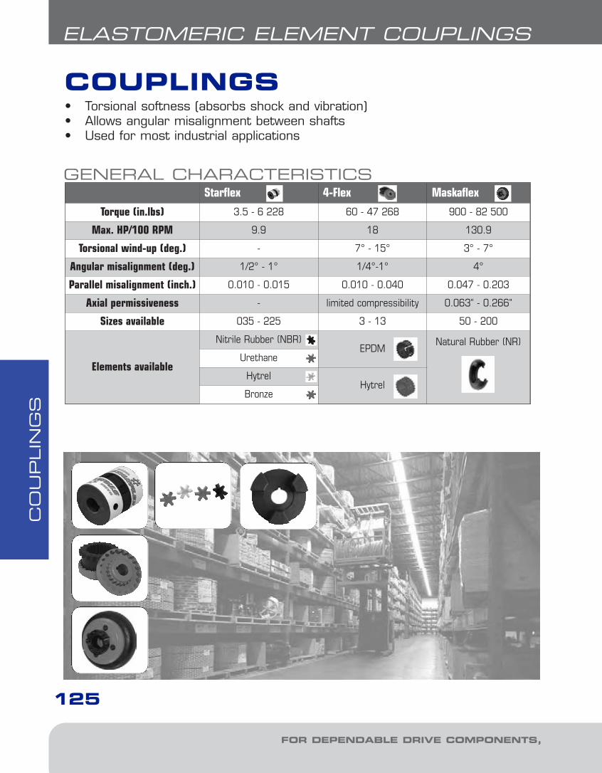
CO
UPLIN
GS
125
ELASTOMERIC ELEMENT COUPLINGS
COUPLINGS
GENERAL CHARACTERISTICSStarflex 4-Flex Maskaflex
Torque (in.lbs) 3.5 - 6 228 60 - 47 268 900 - 82 500
Max. HP/100 RPM 9.9 18 130.9
Torsional wind-up (deg.) - 7° - 15° 3° - 7°
Angular misalignment (deg.) 1/2° - 1° 1/4°-1° 4°
Parallel misalignment (inch.) 0.010 - 0.015 0.010 - 0.040 0.047 - 0.203
Axial permissiveness - limited compressibility 0.063" - 0.266"
Sizes available 035 - 225 3 - 13 50 - 200
Elements available
Nitrile Rubber (NBR)EPDM
Natural Rubber (NR)
Urethane
HytrelHytrel
Bronze
• Torsional softness (absorbs shock and vibration)• Allows angular misalignment between shafts• Used for most industrial applications
FOR DEPENDABLE DRIVE COMPONENTS, BE SURE TO SPECIFY
6-Couplings1.13.qxp 2009-03-19 14:29 Page 2

CO
UPLIN
GS
MASKA FLEXIBLE COUPLING SELECTIONFOR ALL MASKA COUPLING TYPESSelection Process:We will present two different ways of selecting the proper coupling -- namely, the torque designand the HP design.
1. Determine the appropriate Coupling Series and Element materialUsing the General Characteristics chart (pg. 125), determine which coupling series would bemore appropriate for your application. From this information, you may have to choose the proper element material according to the related Element Characteristics chart (Starflex pg. 132; 4-Flex pg. 151).
2. Determine the appropriate Service FactorUsing the Application Service Factors chart (pgs 129-130) and the Driver Service FactorAdders chart (pg. 128), determine the Service Factor that corresponds the closest to your application.
3. a) Determine the Torque Design
Torque Design = (HP x Service Factor x 63025)RPM
3 b) Determine the HP Design per 100 RPM
HP per 100 RPM = (HP x Service Factor x 100)RPM
4 Select the Coupling SizeUsing the Coupling Ratings & Misalignment charts, locate either the Torque or the HP per 100RPM columns. As the service factor has already been considered, use the chart with a servicefactor of 1. Skim this column to the first entry where the torque value or the HP per 100 RPMvalue is greater or equal to the value calculated in step 3. Once this value is located, refer to thecorresponding coupling size in the first column of the chart. Refer to the Maximum RPM andMisalignment values to validate that the application requirements are met. If the requirements arenot met at this point, another coupling type may be required for the application. Contact our technical support for assistance, if needed.
5. Verify the driver/driven shaft sizesUsing the proper coupling Dimensions chart, verify that your driver and driven shaft dimensionsare smaller or equal to the maximum bore size available on the coupling selected. If the couplingbore size is not large enough for the shaft diameter, select the next largest coupling that will fitthe driver/driven shaft diameter.
SELECTION EXAMPLE:A coupling is needed to join a 5 HP electric high torque motor operating at 1750 RPM to an outdoor agricultural belt conveyor. The shaft size of the motor is 1 1/8" and the conveyor is 1 3/16".
1. Determine the appropriate Coupling Series and Element materialAccording to the General Characteristics chart, the proper series to use would be the MASKASTARFLEX to get the smallest back lash. According to the Element Characteristics chart,Urethane would probably be the best choice for this application.
ELASTOMERIC ELEMENT COUPLINGS
126
BE SURE TO SPECIFY
6-Couplings1.13.qxp 2009-03-19 14:29 Page 3
CO
UPLIN
GS
FOR DEPENDABLE DRIVE COMPONENTS, BE SURE TO SPECIFY
127
ELASTOMERIC ELEMENT COUPLINGS
MASKA FLEXIBLE COUPLING SELECTIONCONTINUED2. Determine the appropriate Service FactorTo calculate the appropriate service factor to use with your coupling selection, refer to theApplication Service Factor chart (pgs 129-130) and the Driver Service Factor Adders chart(pg.128). To obtain the Service Factor, the Driver Service Factor adder has to be added (1) to theApplication Service Factor. To calculate the Service Factor for a MASKA STARFLEX used on a beltconveyor driven by a High Torque AC Motor, the application service factor is 1.20 and the driverservice factor adder is 0.25. So, the service factor will be 1.20 + 0.25 = 1.45.
3 a) Determine the Torque Design
Torque Design = HP x Service Factor x 63025 = .RPM
Torque Design = 5 x 1.45 x 63025 = 261.10 in-lbs1750
OR
3 b) Determine the HP Design per 100 RPM
HP per 100 RPM = HP x Service Factor x 100RPM
HP per 100 RPM = 5 x 1.45 x 100 = 0.414 HP per 100 RPM1750
4. Select the Coupling size
Using the Coupling Ratings & Misalignment charts for the MASKA STARFLEX UrethaneElement, locate either the Torque or the HP per 100 RPM columns with a service factor of 1.Skim down this column to the first item that is greater or equal to the Design Torque: 261.10 in-lbs. or to the HP per 100 RPM: 0.414 HP. For this application, the L095 coupling with aNominal Torque rating of 291 in-lbs. and a HP per 100 RPM of 0.462 HP is the proper coupling.
According to this chart, the maximum RPM of 1750 on the electric motor does not exceed the9000 RPM maximum allowed for the L095 sized coupling with a Urethane insert.
5. Verify the driver/driven shaft sizesThe electric motor has a shaft size of 1 1/8" and the conveyor has a shaft size of 1 3/16".Because the maximum bore of the L095 is less than the conveyor shaft size, the L095 couplingis insufficient for this application. Continuing down the maximum bore column in the chart, theL099 size has a maximum bore size of 1 3/16" which is able to accommodate the driver/drivenshaft sizes.
Therefore: The required coupling size for this application is a MASKA STARFLEX L099 witha Urethane Element.
6-Couplings1.13.qxp 2009-03-19 14:29 Page 4
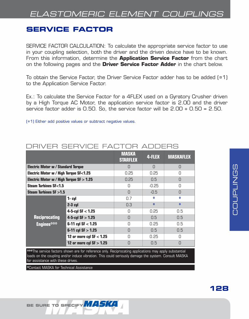
CO
UPLIN
GS
BE SURE TO SPECIFY
128
ELASTOMERIC ELEMENT COUPLINGS
MASKASTARFLEX
4-FLEX MASKAFLEX
Electric Motor w / Standard Torque 0 0 0
Electric Motor w / High Torque SF<1.25 0.25 0.25 0
Electric Motor w / High Torque SF > 1.25 0.25 0.5 0
Steam Turbines SF<1.5 0 -0.25 0
Steam Turbines SF >1.5 0 -0.5 0
ReciprocatingEngines***
1- cyl 0.7 * *2-3 cyl 0.3 * *4-5-cyl SF < 1.25 0 0.25 0.5
4-5-cyl SF > 1.25 0 0.5 0.5
6-11 cyl SF < 1.25 0 0.25 0.5
6-11 cyl SF > 1.25 0 0.5 0.5
12 or more cyl SF < 1.25 0 0.25 0
12 or more cyl SF > 1.25 0 0.5 0
*Contact MASKA for Technical Assistance
***The service factors shown are for reference only. Reciprocating applications may apply substantialloads on the coupling and/or induce vibration. This could seriously damage the system. Consult MASKAfor assistance with these drives.
SERVICE FACTOR
SERVICE FACTOR CALCULATION: To calculate the appropriate service factor to usein your coupling selection, both the driver and the driven device have to be known.From this information, determine the Application Service Factor from the charton the following pages and the Driver Service Factor Adder in the chart below.
To obtain the Service Factor, the Driver Service Factor adder has to be added (¤1)to the Application Service Factor.
Ex.: To calculate the Service Factor for a 4FLEX used on a Gyratory Crusher drivenby a High Torque AC Motor, the application service factor is 2.00 and the driverservice factor adder is 0.50. So, the service factor will be 2.00 + 0.50 = 2.50.
(¤1) Either add positive values or subtract negative values.
DRIVER SERVICE FACTOR ADDERS
6-Couplings1.13.qxp 2009-03-19 14:29 Page 5

CO
UPLIN
GS
129
ELASTOMERIC ELEMENT COUPLINGS
APPLICATION SERVICE FACTORS MASKA STARFLEX 4-FLEX MASKAFLEXAgitators 1.00 1.25 1.00BlowersCentrifugalLobeVane
1.001.251.25
1.251.501.25
1.001.501.00
Brewing & distillingBottling Machinery, Brew Kettles (distilling)Cookers
1.251.25
1.251.25
1.001.00
Car Dumpers 2.50 2.00 1.50Car Pullers 1.50 2.00 1.50Compressors **CentrifugalScrewLobeReciprocating1 cylinder - single acting1 cylinder - double acting2 cylinder- single acting2 cylinder - double acting3 cl, or more - single acting3 cl, or more - double acting
1.001.251.25
******
1.251.251.25
******
1.001.002.00
3.503.003.002.502.502.00
ConveyorsAssembly, Belt, Oven, Screw 1.2 1.25 1.00Cranes & HoistMain Hoist-Medium DutyMain Hoist-Heavy Duty
1.502.00
1.502.00
1.502.00
CrushersCaneGyratory
3.503.00
2.002.00
2.002.50
DredgesCable reelsCutter Head DrivesManeuvering and Utility Winch, Pumps
2.002.501.50
1.502.001.50
1.502.501.50
Dynamometer 1.50 1.25 1.00FansCentrifugalCooling TowersForced Draft Propeller
1.002.001.50
1.252.001.50
1.002.001.50
FeedersBeltScrewReciprocatingFilter, Press-oil
1.001.002.501.50
1.251.502.001.50
----
GeneratorsNot WeldingHoistWelding
1.001.502.00
1.251.502.00
1.001.502.00
Kilns 1.50 2.00 2.00Lumber MachineryBand ResawBarkers, Edger Feeder, LOG HAULPlaner, Slab ConveyorLive Roll - ReciprocatingSawdust Conveyor
1.502.002.002.001.25
1.502.001.50
-1.25
1.502.001.502.001.00
SERVICE FACTOR (continued)
FOR DEPENDABLE DRIVE COMPONENTS, BE SURE TO SPECIFY
6-Couplings1.13.qxp 2009-03-19 14:29 Page 6

CO
UPLIN
GS
130
ELASTOMERIC ELEMENT COUPLINGS
APPLICATION SERVICE FACTORS MASKA STARFLEX 4-FLEX MASKAFLEXMachine ToolsMain DrivePunch Press-gear Driven, Plate Planer
1.502.00
1.501.50
1.501.50
Metal Forming MachinesDraw Bench, Carriage & Main DriveExtruderWire Drawing
2.002.002.00
2.002.002.00
2.002.002.00
Mills, Rotary TypeBall, PebbleTubeRodDryers, CoolersTumbling, Tumbling Barrel, Rubber Tumbling
2.002.002.002.001.50
2.002.002.001.502.00
2.502.502.501.501.50
MixersConcrete, continuousMuller
1.751.50
1.501.50
1.501.50
Oil IndustryChiller (oil)
1.50 1.50 1.00
Paper MillsAgitator (mixers), Reel, WinderBarking DrumBeater, PulperJordansCalendersSuction Roll (paper)Winder
1.202.502.002.001.501.501.20
1.502.001.502.002.001.501.50
1.002.501.502.002.002.001.50
Printing Presses 1.50 1.50 1.50Barge Haul Puller 2.00 2.00 2.50PulverisersHammermill-Light DutyHammermill-Heavy Duty
2.002.00
1.502.00
1.502.00
Pug Mill 1.75 1.50 1.50PumpsCentrifugalGearReciprocating:1–Cyl, Single Acting1–Cyl, Double Acting2–Cyl, Single Acting2–Cyl, Double Acting3 or more Cyl
1.001.25
2.002.002.001.751.50
1.251.50
*****
1.001.50
2.502.002.001.501.50
Rubber MachineryBanbury MixersCalender
2.502.00
2.002.00
2.502.00
ScreensAir washing, WaterCoal and Sand RotaryVibratingGrizzly
1.001.502.502.00
1.251.502.002.00
1.001.502.502.00
Textile MachineryCard MachineMangelLoom, Spinner, Tenter framesTumbling Barrels
1.751.201.501.75
2.001.251.502.00
1.501.001.502.00
Windlass 2.00 1.50 1.50Woodworking Machines 1.00 1.25 1.00
*Contact MASKA for technical assistance** Add 0.5 to factor if without flywheel
BE SURE TO SPECIFY
6-Couplings1.13.qxp 2009-03-19 14:29 Page 7
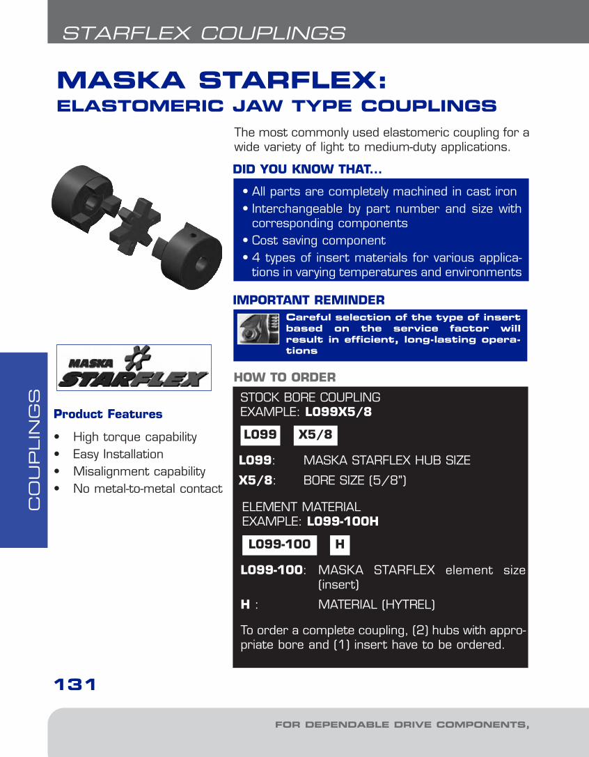
CO
UPLIN
GS
MASKA STARFLEX:ELASTOMERIC JAW TYPE COUPLINGS
131
STARFLEX COUPLINGS
STOCK BORE COUPLINGEXAMPLE: L099X5/8
L099 X5/8
L099: MASKA STARFLEX HUB SIZE
X5/8: BORE SIZE (5/8")
HOW TO ORDER
Careful selection of the type of insertbased on the service factor willresult in efficient, long-lasting opera-tions
IMPORTANT REMINDER
The most commonly used elastomeric coupling for awide variety of light to medium-duty applications.
• All parts are completely machined in cast iron• Interchangeable by part number and size with
corresponding components• Cost saving component• 4 types of insert materials for various applica-
tions in varying temperatures and environments
DID YOU KNOW THAT...
ELEMENT MATERIALEXAMPLE: L099-100H
L099-100 H
L099-100: MASKA STARFLEX element size(insert)
H : MATERIAL (HYTREL)
To order a complete coupling, (2) hubs with appro-priate bore and (1) insert have to be ordered.
Product Features
• High torque capability• Easy Installation• Misalignment capability• No metal-to-metal contact
FOR DEPENDABLE DRIVE COMPONENTS, BE SURE TO SPECIFY
6-Couplings1.13.qxp 2009-03-19 14:29 Page 8

CO
UPLIN
GS
132
STARFLEX COUPLINGS
ELEMENT CHARACTERISTICS
PropertiesTemperature
Range
MisalignmentShore
HardnessDampeningCapacity
ChemicalResistance
ColourAngularDegree
ParallelInch
NBR (Rubber) Nitrile Butadiene Rubberis an elastomeric element that is oilresistant with the resilience and elasticity of natural rubber.
Most economical and widely-usedelement.
-40° to +212° F
-40° to +100°C
1° .015 80A HIGH GOOD
BLACK
Urethane -- Urethane has 1.5 moretorque capability than NBR, providesless dampening effect and has good resistance to oil and chemicals.
Not recommended for cyclic or start-stop applications.
-30° to +160° F
-34° to +71° C1° .015
55DL050-L110
90-95AL150-L225
LOW VERY GOOD
ORANGE
Hytrel -- Hytrel is a pliant elastomer suited to high torque / temperatureoperations. Notable resistance to oil andchemincals
Not recommended for cyclic or start-stop applications.
-60° to +250° F
-51° to 121° C1/2° .015 55D LOW EXCELLENT
BEIGE
Bronze -- Bronze is a metal insertdesigned exclusively for slow speed )operations that require high torque.(Maximum 250 RPM)
Resistant to extreme environments (temperature, water, oil, dirt).
-40° to +450° F
-40° to +232°C
1/2° .010 -- NIL EXCELLENT
GOLD
Jaw Couplings AdvantagesJaw design is considered “fail-safe” - if theinsert element wears/breaks away, the coupling continues to operate until insert canbe conveniently replaced.
Simple design means easy installation, removaland visual inspection. Also offers lighter weightand lower cost vs. torque capacity.
Insert ChoiceThe choice of the insert element can make a significant difference in the couplings’s performance with regards to vibration, temperature, chemicals, misalignment, high rpm,space limitations and installation/removal.
Maintenance TipsThrough manual inspection, avoid allowing thejaw tips to come into contact; a noisy, grindingoperation will result. Do not hesitate to replacethe insert if signs of wear are evident.
Do not over-estimate service factors whenchoosing the coupling / insert. This increasescosts unnecessarily and can cause damageelsewhere in the drive. Due to the variety ofinserts available, careful selection will result inefficient, long-lasting operations.
Selecting the proper insert material is just as important asselecting the correct type and size of jaw coupling because of therole they play in the performance and maintenance of the product.
IMPORTANT REMINDER
BE SURE TO SPECIFY
6-Couplings1.13.qxp 2009-03-19 14:29 Page 9
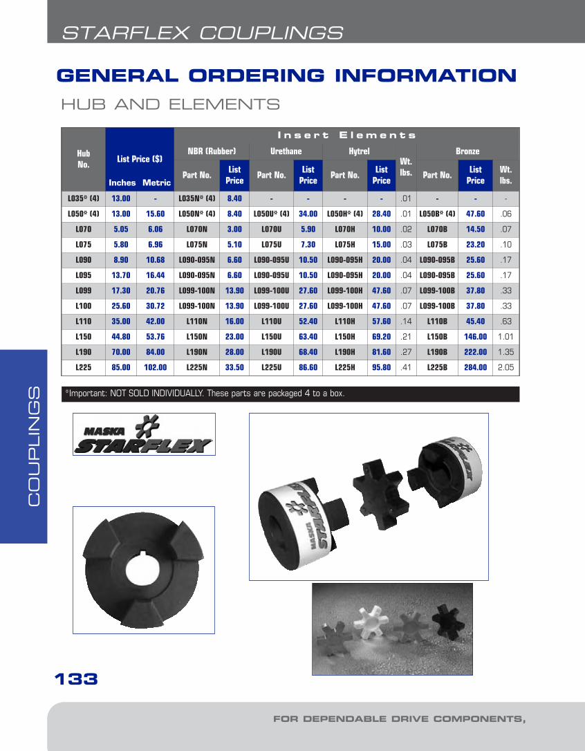
CO
UPLIN
GS
133
STARFLEX COUPLINGS
HUB AND ELEMENTS
GENERAL ORDERING INFORMATION
FOR DEPENDABLE DRIVE COMPONENTS, BE SURE TO SPECIFY
*Important: NOT SOLD INDIVIDUALLY. These parts are packaged 4 to a box.
HubNo.
List Price ($)
I n s e r t E l e m e n t s
NBR (Rubber) Urethane HytrelWt.lbs.
Bronze
Part No.List
PricePart No.
ListPrice
Part No.List
PricePart No.
ListPrice
Wt.lbs.
L035* (4) 13.00 - L035N* (4) 8.40 - - - - .01 - - -
L050* (4) 13.00 15.60 L050N* (4) 8.40 L050U* (4) 34.00 L050H* (4) 28.40 .01 L050B* (4) 47.60 .06
L070 5.05 6.06 L070N 3.00 L070U 5.90 L070H 10.00 .02 L070B 14.50 .07
L075 5.80 6.96 L075N 5.10 L075U 7.30 L075H 15.00 .03 L075B 23.20 .10
L090 8.90 10.68 L090-095N 6.60 L090-095U 10.50 L090-095H 20.00 .04 L090-095B 25.60 .17
L095 13.70 16.44 L090-095N 6.60 L090-095U 10.50 L090-095H 20.00 .04 L090-095B 25.60 .17
L099 17.30 20.76 L099-100N 13.90 L099-100U 27.60 L099-100H 47.60 .07 L099-100B 37.80 .33
L100 25.60 30.72 L099-100N 13.90 L099-100U 27.60 L099-100H 47.60 .07 L099-100B 37.80 .33
L110 35.00 42.00 L110N 16.00 L110U 52.40 L110H 57.60 .14 L110B 45.40 .63
L150 44.80 53.76 L150N 23.00 L150U 63.40 L150H 69.20 .21 L150B 146.00 1.01
L190 70.00 84.00 L190N 28.00 L190U 68.40 L190H 81.60 .27 L190B 222.00 1.35
L225 85.00 102.00 L225N 33.50 L225U 86.60 L225H 95.80 .41 L225B 284.00 2.05
Inches Metric
6-Couplings1.13.qxp 2009-03-19 14:29 Page 10
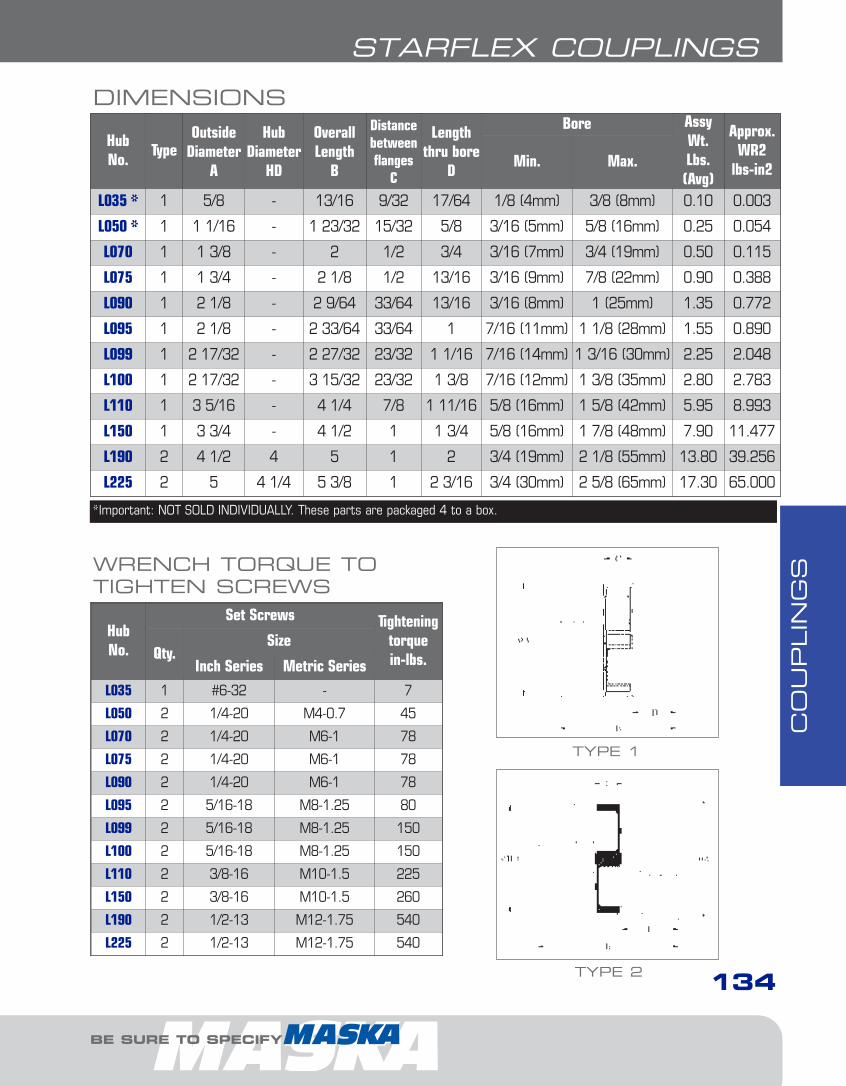
CO
UPLIN
GS
STARFLEX COUPLINGS
HubNo.
TypeOutside
DiameterA
HubDiameter
HD
OverallLength
B
Distancebetweenflanges
C
Lengththru bore
D
Bore AssyWt.Lbs.(Avg)
Approx.WR2
lbs-in2Min. Max.
L035 * 1 5/8 - 13/16 9/32 17/64 1/8 (4mm) 3/8 (8mm) 0.10 0.003
L050 * 1 1 1/16 - 1 23/32 15/32 5/8 3/16 (5mm) 5/8 (16mm) 0.25 0.054
L070 1 1 3/8 - 2 1/2 3/4 3/16 (7mm) 3/4 (19mm) 0.50 0.115
L075 1 1 3/4 - 2 1/8 1/2 13/16 3/16 (9mm) 7/8 (22mm) 0.90 0.388
L090 1 2 1/8 - 2 9/64 33/64 13/16 3/16 (8mm) 1 (25mm) 1.35 0.772
L095 1 2 1/8 - 2 33/64 33/64 1 7/16 (11mm) 1 1/8 (28mm) 1.55 0.890
L099 1 2 17/32 - 2 27/32 23/32 1 1/16 7/16 (14mm) 1 3/16 (30mm) 2.25 2.048
L100 1 2 17/32 - 3 15/32 23/32 1 3/8 7/16 (12mm) 1 3/8 (35mm) 2.80 2.783
L110 1 3 5/16 - 4 1/4 7/8 1 11/16 5/8 (16mm) 1 5/8 (42mm) 5.95 8.993
L150 1 3 3/4 - 4 1/2 1 1 3/4 5/8 (16mm) 1 7/8 (48mm) 7.90 11.477
L190 2 4 1/2 4 5 1 2 3/4 (19mm) 2 1/8 (55mm) 13.80 39.256
L225 2 5 4 1/4 5 3/8 1 2 3/16 3/4 (30mm) 2 5/8 (65mm) 17.30 65.000
HubNo.
Set Screws Tighteningtorque in-lbs.Qty.
Size
Inch Series Metric Series
L035 1 #6-32 - 7
L050 2 1/4-20 M4-0.7 45
L070 2 1/4-20 M6-1 78
L075 2 1/4-20 M6-1 78
L090 2 1/4-20 M6-1 78
L095 2 5/16-18 M8-1.25 80
L099 2 5/16-18 M8-1.25 150
L100 2 5/16-18 M8-1.25 150
L110 2 3/8-16 M10-1.5 225
L150 2 3/8-16 M10-1.5 260
L190 2 1/2-13 M12-1.75 540
L225 2 1/2-13 M12-1.75 540
DIMENSIONS
WRENCH TORQUE TO TIGHTEN SCREWS
*Important: NOT SOLD INDIVIDUALLY. These parts are packaged 4 to a box.
TYPE 2
TYPE 1
BE SURE TO SPECIFY
134
6-Couplings1.13.qxp 2009-03-19 14:29 Page 11
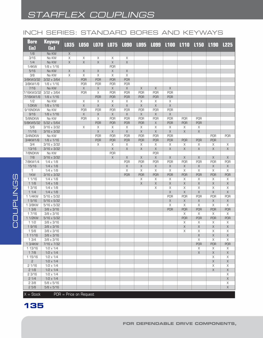
CO
UPLIN
GS
Bore(in)
Keyway(in)
L035 L050 L070 L075 L090 L095 L099 L100 L110 L150 L190 L225
1/8 No KW X3/16 No KW X X X X X1/4 No KW X X X X X
1/4KW 1/8 x 1/16 POR5/16 No KW X X X X X3/8 No KW X X X X X
3/8KW3/32 3/32 x 3/64 POR POR POR POR3/8KW1/8 1/8 x 1/16 POR POR POR POR
7/16 No KW X X X X X X X7/16KW3/32 3/32 x 3/64 POR X POR POR POR POR POR7/16KW1/8 1/8 x 1/16 POR POR POR POR POR POR
1/2 No KW X X X X X X X1/2KW 1/8 x 1/16 X X X X X X X
9/16NOKW No KW POR POR POR POR POR POR POR9/16 1/8 x 1/16 X X X X X X X
5/8NOKW No KW POR X POR POR POR POR POR POR POR5/8KW5/32 5/32 x 5/64 POR POR POR POR X POR POR POR
5/8 3/16 x 3/32 X X X X X X X X X11/16 3/16 x 3/32 X X X X X X X X
3/4NOKW No KW POR POR POR POR POR POR POR POR3/4KW1/8 1/8 x 1/16 POR POR POR POR POR POR POR POR POR
3/4 3/16 x 3/32 X X X X X X X X X X13/16 3/16 x 3/32 X X X X X X X X X
7/8NOKW No KW POR POR7/8 3/16 x 3/32 X X X X X X X X X
7/8KW1/4 1/4 x 1/8 POR POR POR POR POR POR POR POR15/16 1/4 x 1/8 X X X X X X X X
1 1/4 x 1/8 X X X X X X X X1KW 3/16 x 3/32 POR POR POR POR POR POR POR POR
1 1/16 1/4 x 1/8 X X X X X X X1 1/8 1/4 x 1/8 X X X X X X X1 3/16 1/4 x 1/8 X X X X X X1 1/4 1/4 x 1/8 X X X X X
1 1/4KW 5/16 x 5/32 POR POR POR POR POR1 5/16 5/16 x 5/32 X X X X X
1 3/8KW 5/16 x 5/32 X X X X X1 3/8 3/8 x 3/16 POR POR POR POR POR1 7/16 3/8 x 3/16 X X X X
1 1/2KW 5/16 x 5/32 POR POR POR POR1 1/2 3/8 x 3/16 X X X X1 9/16 3/8 x 3/16 X X X X1 5/8 3/8 x 3/16 X X X X
1 11/16 3/8 x 3/16 X X X1 3/4 3/8 x 3/16 X X X
1 3/4KW 7/16 x 7/32 POR POR POR1 13/16 1/2 x 1/4 X X X1 7/8 1/2 x 1/4 X X X
1 15/16 1/2 x 1/4 X X2 1/2 x 1/4 X X
2 1/16 1/2 x 1/4 X X2 1/8 1/2 x 1/4 X X2 3/16 1/2 x 1/4 X2 1/4 1/2 x 1/4 X2 3/8 5/8 x 5/16 X2 5/8 5/8 x 5/16 X
INCH SERIES: STANDARD BORES AND KEYWAYS
X = Stock POR = Price on Request
135
STARFLEX COUPLINGS
FOR DEPENDABLE DRIVE COMPONENTS, BE SURE TO SPECIFY
6-Couplings1.13.qxp 2009-03-19 14:29 Page 12
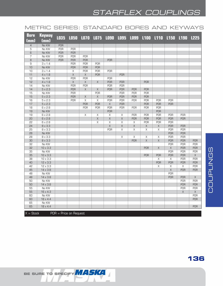
CO
UPLIN
GS
136
STARFLEX COUPLINGS
Bore(mm)
Keyway(mm)
L035 L050 L070 L075 L090 L095 L099 L100 L110 L150 L190 L225
4 No KW POR5 No KW POR POR6 No KW POR POR7 No KW POR POR POR8 No KW POR POR POR POR9 3 x 1.4 POR POR POR10 No KW POR POR POR10 3 x 1.4 X POR POR POR11 4 x 1.8 X X POR POR12 No KW POR POR POR12 4 x 1.8 X X X POR POR POR14 No KW POR POR POR POR14 5 x 2.3 POR X X POR POR POR POR15 No KW POR POR POR POR POR15 5 x 2.3 POR X X POR POR POR POR16 5 x 2.3 POR X X POR POR POR POR POR POR17 5 x 2.3 POR POR X POR POR POR POR18 6 x 2.8 POR POR POR POR POR POR POR19 No KW POR POR19 6 x 2.8 X X X X POR POR POR POR POR20 6 x 2.8 X X X POR POR POR POR POR22 6 x 2.8 X X X X POR POR POR24 8 x 3.3 X X X X X POR POR25 8 x 3.3 POR X X X X POR POR28 No KW POR POR28 8 x 3.3 X X X X POR POR30 8 x 3.3 POR X X POR POR POR32 No KW POR POR POR32 10 x 3.3 POR X X POR POR35 No KW POR POR POR35 10 x 3.3 POR POR POR POR X38 10 x 3.3 X X POR POR40 12 x 3.3 POR POR POR POR42 12 x 3.3 X X X POR45 14 x 3.8 X POR POR48 No KW POR48 14 x 3.8 POR POR X50 No KW POR POR50 14 x 3.8 POR POR55 No KW POR POR55 16 x 4.3 X X60 No KW POR60 18 x 4.4 POR65 No KW 65 18 x 4.4 POR
METRIC SERIES: STANDARD BORES AND KEYWAYS
X = Stock POR = Price on Request
STARFLEX COUPLINGS
BE SURE TO SPECIFY
6-Couplings1.13.qxp 2009-03-19 14:29 Page 13
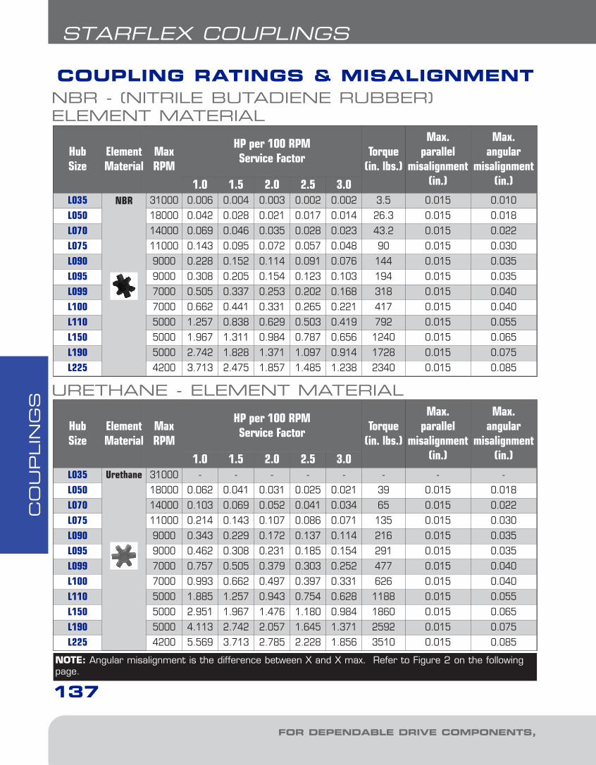
CO
UPLIN
GS
137
STARFLEX COUPLINGS
COUPLING RATINGS & MISALIGNMENT
Hub Size
ElementMaterial
MaxRPM
HP per 100 RPMService Factor Torque
(in. lbs.)
Max. parallel
misalignment(in.)
Max. angular
misalignment(in.)1.0 1.5 2.0 2.5 3.0
L035 NBR 31000 0.006 0.004 0.003 0.002 0.002 3.5 0.015 0.010
L050 18000 0.042 0.028 0.021 0.017 0.014 26.3 0.015 0.018
L070 14000 0.069 0.046 0.035 0.028 0.023 43.2 0.015 0.022
L075 11000 0.143 0.095 0.072 0.057 0.048 90 0.015 0.030
L090 9000 0.228 0.152 0.114 0.091 0.076 144 0.015 0.035
L095 9000 0.308 0.205 0.154 0.123 0.103 194 0.015 0.035
L099 7000 0.505 0.337 0.253 0.202 0.168 318 0.015 0.040
L100 7000 0.662 0.441 0.331 0.265 0.221 417 0.015 0.040
L110 5000 1.257 0.838 0.629 0.503 0.419 792 0.015 0.055
L150 5000 1.967 1.311 0.984 0.787 0.656 1240 0.015 0.065
L190 5000 2.742 1.828 1.371 1.097 0.914 1728 0.015 0.075
L225 4200 3.713 2.475 1.857 1.485 1.238 2340 0.015 0.085
NBR - (NITRILE BUTADIENE RUBBER) ELEMENT MATERIAL
Hub Size
ElementMaterial
MaxRPM
HP per 100 RPMService Factor Torque
(in. lbs.)
Max. parallel
misalignment(in.)
Max. angular
misalignment(in.)1.0 1.5 2.0 2.5 3.0
L035 Urethane 31000 - - - - - - - -
L050 18000 0.062 0.041 0.031 0.025 0.021 39 0.015 0.018
L070 14000 0.103 0.069 0.052 0.041 0.034 65 0.015 0.022
L075 11000 0.214 0.143 0.107 0.086 0.071 135 0.015 0.030
L090 9000 0.343 0.229 0.172 0.137 0.114 216 0.015 0.035
L095 9000 0.462 0.308 0.231 0.185 0.154 291 0.015 0.035
L099 7000 0.757 0.505 0.379 0.303 0.252 477 0.015 0.040
L100 7000 0.993 0.662 0.497 0.397 0.331 626 0.015 0.040
L110 5000 1.885 1.257 0.943 0.754 0.628 1188 0.015 0.055
L150 5000 2.951 1.967 1.476 1.180 0.984 1860 0.015 0.065
L190 5000 4.113 2.742 2.057 1.645 1.371 2592 0.015 0.075
L225 4200 5.569 3.713 2.785 2.228 1.856 3510 0.015 0.085
URETHANE - ELEMENT MATERIAL
NOTE: Angular misalignment is the difference between X and X max. Refer to Figure 2 on the followingpage.
FOR DEPENDABLE DRIVE COMPONENTS, BE SURE TO SPECIFY
6-Couplings1.13.qxp 2009-03-19 14:29 Page 14
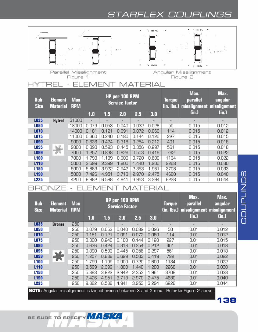
CO
UPLIN
GS
138
STARFLEX COUPLINGS
HubSize
ElementMaterial
MaxRPM
HP per 100 RPMService Factor Torque
(in. lbs.)
Max. parallel
misalignment(in.)
Max. angular
misalignment(in.)1.0 1.5 2.0 2.5 3.0
L035 Hytrel 31000 - - - - - - - -L050 18000 0.079 0.053 0.040 0.032 0.026 50 0.015 0.012L070 14000 0.181 0.121 0.091 0.072 0.060 114 0.015 0.012L075 11000 0.360 0.240 0.180 0.144 0.120 227 0.015 0.015L090 9000 0.636 0.424 0.318 0.254 0.212 401 0.015 0.018L095 9000 0.890 0.593 0.445 0.356 0.297 561 0.015 0.018L099 7000 1.257 0.838 0.629 0.503 0.419 792 0.015 0.022L100 7000 1.799 1.199 0.900 0.720 0.600 1134 0.015 0.022L110 5000 3.599 2.399 1.800 1.440 1.200 2268 0.015 0.030L150 5000 5.883 3.922 2.942 2.353 1.961 3708 0.015 0.033L190 5000 7.426 4.951 3.713 2.970 2.475 4680 0.015 0.040L225 4200 9.882 6.588 4.941 3.953 3.294 6228 0.015 0.044
HYTREL - ELEMENT MATERIAL
Hub Size
ElementMaterial
MaxRPM
HP per 100 RPMService Factor Torque
(in. lbs.)
Max. parallel
misalignment(in.)
Max. angular
misalignment(in.)1.0 1.5 2.0 2.5 3.0
L035 Bronze 250 - - - - - - - -L050 250 0.079 0.053 0.040 0.032 0.026 50 0.01 0.012L070 250 0.181 0.121 0.091 0.072 0.060 114 0.01 0.012L075 250 0.360 0.240 0.180 0.144 0.120 227 0.01 0.015L090 250 0.636 0.424 0.318 0.254 0.212 401 0.01 0.018L095 250 0.890 0.593 0.445 0.356 0.297 561 0.01 0.018L099 250 1.257 0.838 0.629 0.503 0.419 792 0.01 0.022L100 250 1.799 1.199 0.900 0.720 0.600 1134 0.01 0.022L110 250 3.599 2.399 1.800 1.440 1.200 2268 0.01 0.030L150 250 5.883 3.922 2.942 2.353 1.961 3708 0.01 0.033L190 250 7.426 4.951 3.713 2.970 2.475 4680 0.01 0.040L225 250 9.882 6.588 4.941 3.953 3.294 6228 0.01 0.044
BRONZE - ELEMENT MATERIAL
Parallel MisalignmentFigure 1
Angular MisalignmentFigure 2
NOTE: Angular misalignment is the difference between X and X max. Refer to Figure 2 above.
BE SURE TO SPECIFY
6-Couplings1.13.qxp 2009-03-19 14:30 Page 15

CO
UPLIN
GS
139
STARFLEX COUPLINGS
860 RPM MOTORS 1160 RPM MOTORS
HP Service Factors HP Service Factors1.0 1.25 1.5 2.0 2.5 1.0 1.25 1.5 2.0 2.5
1/8 L050 L050 L050 L050 L050 1/8 L050 L050 L050 L050 L050
1/4 L050 L050 L070 L070 L075 1/4 L050 L050 L050 L070 L070
1/3 L050 L070 L070 L075 L075 1/3 L050 L050 L070 L070 L075
1/2 L070 L075 L075 L075 L090 1/2 L070 L070 L070 L075 L075
3/4 L075 L075 L075 L090 L090 3/4 L070 L075 L075 L075 L090
1 L075 L090 L090 L095 L095 1 L075 L075 L075 L090 L090
1 1/2 L090 L090 L095 L099 L099 1 1/2 L075 L090 L090 L095 L099
2 L095 L095 L099 L099 L100 2 L090 L090 L095 L099 L099
3 L099 L099 L100 L110 L110 3 L095 L099 L099 L100 L100
5 L100 L110 L110 L110 L150 5 L099 L100 L100 L110 L110
7 1/2 L110 L110 L150 L150 L190 7 1/2 L100 L110 L110 L150 L150
10 L110 L150 L150 L190 L225 10 L110 L110 L150 L150 L190
15 L150 L190 L190 L225 - 15 L150 L150 L150 L190 L225
20 L190 L225 L225 - - 20 L150 L190 L190 L225 -
25 L225 L225 - - - 25 L190 L190 L225 - -
30 L225 - - - - 30 L190 L225 - - -
40 - - - - - 40 L225 - - - -
50 - - - - - 50 - - - - -
60 - - - - - 60 - - - - -
75 - - - - - 75 - - - - -
NBR - (NITRILE BUTADIENE RUBBER) ELEMENT MATERIAL
COUPLING SELECTION - SERVICE FACTORS FOR ELEMENT MATERIALS
FOR DEPENDABLE DRIVE COMPONENTS, BE SURE TO SPECIFY
6-Couplings1.13.qxp 2009-03-19 14:30 Page 16
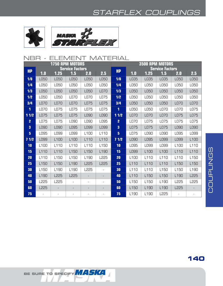
CO
UPLIN
GS
140
STARFLEX COUPLINGS
1750 RPM MOTORS 3500 RPM MOTORS
HP Service Factors HP Service Factors1.0 1.25 1.5 2.0 2.5 1.0 1.25 1.5 2.0 2.5
1/8 L050 L050 L050 L050 L050 1/8 L035 L035 L035 L050 L050
1/4 L050 L050 L050 L050 L050 1/4 L050 L050 L050 L050 L050
1/3 L050 L050 L050 L050 L070 1/3 L050 L050 L050 L050 L050
1/2 L050 L050 L070 L070 L075 1/2 L050 L050 L050 L050 L050
3/4 L070 L070 L070 L075 L075 3/4 L050 L050 L050 L070 L070
1 L070 L075 L075 L075 L075 1 L050 L050 L070 L070 L075
1 1/2 L075 L075 L075 L090 L090 1 1/2 L070 L070 L070 L075 L075
2 L075 L075 L090 L090 L095 2 L070 L075 L075 L075 L075
3 L090 L090 L095 L099 L099 3 L075 L075 L075 L090 L090
5 L095 L099 L099 L100 L110 5 L075 L090 L090 L095 L099
7 1/2 L099 L100 L100 L110 L110 7 1/2 L090 L095 L099 L099 L100
10 L100 L110 L110 L110 L150 10 L095 L099 L099 L100 L110
15 L110 L110 L150 L150 L190 15 L099 L100 L100 L110 L110
20 L110 L150 L150 L190 L225 20 L100 L110 L110 L110 L150
25 L150 L150 L190 L225 L225 25 L110 L110 L110 L150 L150
30 L150 L190 L190 L225 - 30 L110 L110 L150 L150 L190
40 L190 L225 L225 - - 40 L110 L150 L150 L190 L225
50 L225 L225 - - - 50 L150 L150 L190 L225 L225
60 L225 - - - - 60 L150 L190 L190 L225 -
75 - - - - - 75 L190 L190 L225 - -
NBR - ELEMENT MATERIAL
BE SURE TO SPECIFY
6-Couplings1.13.qxp 2009-03-19 14:30 Page 17

CO
UPLIN
GS
141
STARFLEX COUPLINGS
860 RPM MOTORS 1160 RPM MOTORS
HP Service Factors HP Service Factors1.0 1.25 1.5 2.0 2.5 1.0 1.25 1.5 2.0 2.5
1/8 L050 L050 L050 L050 L050 1/8 L050 L050 L050 L050 L050
1/4 L050 L050 L050 L050 L070 1/4 L050 L050 L050 L050 L050
1/3 L050 L050 L050 L070 L070 1/3 L050 L050 L050 L050 L070
1/2 L050 L070 L070 L075 L075 1/2 L050 L050 L070 L070 L075
3/4 L070 L075 L075 L075 L090 3/4 L070 L070 L070 L075 L075
1 L075 L075 L075 L090 L090 1 L070 L075 L075 L075 L075
1 1/2 L075 L090 L090 L095 L095 1 1/2 L075 L075 L075 L090 L090
2 L090 L090 L095 L095 L099 2 L075 L075 L090 L090 L095
3 L095 L095 L099 L099 L100 3 L090 L090 L095 L099 L099
5 L099 L099 L100 L110 L110 5 L095 L099 L099 L100 L110
7 1/2 L100 L110 L110 L110 L150 7 1/2 L099 L100 L100 L110 L110
10 L110 L110 L110 L150 L150 10 L100 L110 L110 L110 L150
15 L110 L150 L150 L190 L225 15 L110 L110 L150 L150 L190
20 L150 L150 L190 L225 - 20 L110 L150 L150 L190 L225
25 L150 L190 L225 - - 25 L150 L150 L190 L225 L225
30 L190 L225 L225 - - 30 L150 L190 L190 L225 -
40 L225 - - - - 40 L190 L225 L225 - -
50 - - - - - 50 L225 L225 - - -
60 - - - - - 60 L225 - - - -
75 - - - - - 75 - - - - -
100 - - - - - 100 - - - - -
125 - - - - - 125 - - - - -
150 - - - - - 150 - - - - -
URETHANE - ELEMENT MATERIAL
COUPLING SELECTION - SERVICEFACTORS FOR ELEMENT MATERIALSCONTINUED
FOR DEPENDABLE DRIVE COMPONENTS, BE SURE TO SPECIFY
6-Couplings1.13.qxp 2009-03-19 14:30 Page 18

CO
UPLIN
GS
142
STARFLEX COUPLINGS
1750 RPM MOTORS 3500 RPM MOTORS
HP Service Factors HP Service Factors1.0 1.25 1.5 2.0 2.5 1.0 1.25 1.5 2.0 2.5
1/8 L050 L050 L050 L050 L050 1/8 L050 L050 L050 L050 L050
1/4 L050 L050 L050 L050 L050 1/4 L050 L050 L050 L050 L050
1/3 L050 L050 L050 L050 L050 1/3 L050 L050 L050 L050 L050
1/2 L050 L050 L050 L050 L070 1/2 L050 L050 L050 L050 L050
3/4 L050 L050 L070 L070 L075 3/4 L050 L050 L050 L050 L050
1 L050 L070 L070 L075 L075 1 L050 L050 L050 L050 L070
1 1/2 L070 L075 L075 L075 L075 1 1/2 L050 L050 L070 L070 L075
2 L075 L075 L075 L090 L090 2 L050 L070 L070 L075 L075
3 L075 L075 L090 L090 L095 3 L070 L075 L075 L075 L075
5 L090 L095 L095 L099 L099 5 L075 L075 L075 L090 L095
7 1/2 L095 L099 L099 L100 L110 7 1/2 L075 L090 L090 L095 L099
10 L099 L099 L100 L110 L110 10 L090 L095 L095 L099 L099
15 L100 L110 L110 L110 L150 15 L095 L099 L099 L100 L110
20 L110 L110 L110 L150 L150 20 L099 L099 L100 L110 L110
25 L110 L110 L150 L150 L190 25 L099 L100 L110 L110 L110
30 L110 L150 L150 L190 L225 30 L100 L110 L110 L110 L150
40 L150 L150 L190 L225 - 40 L110 L110 L110 L150 L150
50 L150 L190 L225 - 50 L110 L110 L150 L150 L190
60 L190 L225 L225 - - 60 L110 L150 L150 L190 L225
75 L225 L225 - - - 75 L150 L150 L190 L225 L225
100 - - - 100 L150 L190 L225 - -
125 - - - 125 L190 L225 L225 - -
150 - - - 150 L225 L225 - - -
URETHANE - ELEMENT MATERIAL
BE SURE TO SPECIFY
6-Couplings1.13.qxp 2009-03-19 14:30 Page 19

CO
UPLIN
GS
143
STARFLEX COUPLINGS
860 RPM MOTORS 1160 RPM MOTORS
HP Service Factors HP Service Factors1.0 1.25 1.5 2.0 2.5 1.0 1.25 1.5 2.0 2.5
1/8 L050 L050 L050 L050 L050 1/8 L050 L050 L050 L050 L050
1/4 L050 L050 L050 L050 L050 1/4 L050 L050 L050 L050 L050
1/3 L050 L050 L050 L050 L070 1/3 L050 L050 L050 L050 L050
1/2 L050 L050 L070 L070 L070 1/2 L050 L050 L050 L070 L070
3/4 L070 L070 L070 L070 L075 3/4 L050 L070 L070 L070 L070
1 L070 L070 L070 L075 L075 1 L070 L070 L070 L070 L075
1 1/2 L070 L075 L075 L075 L090 1 1/2 L070 L070 L075 L075 L075
2 L075 L075 L075 L090 L090 2 L070 L075 L075 L075 L090
3 L075 L090 L090 L095 L095 3 L075 L075 L090 L090 L095
5 L090 L095 L095 L099 L100 5 L090 L090 L095 L095 L099
7 1/2 L095 L099 L100 L100 L110 7 1/2 L095 L095 L099 L100 L100
10 L099 L100 L100 L110 L110 10 L095 L099 L100 L100 L110
15 L100 L110 L110 L110 L150 15 L100 L100 L110 L110 L110
20 L110 L110 L110 L150 L150 20 L100 L110 L110 L110 L150
25 L110 L110 L150 L150 L190 25 L110 L110 L110 L150 L150
30 L110 L150 L150 L190 L225 30 L110 L110 L150 L150 L190
40 L150 L150 L190 L225 - 40 L110 L150 L150 L190 L225
50 L150 L190 L225 - - 50 L150 L150 L190 L225 -
60 L190 L225 - - - 60 L150 L190 L225 - -
75 L225 - - - - 75 L190 L225 L225 - -
100 - - - - - 100 L225 - - - -
125 - - - - - 125 - - - - -
150 - - - - - 150 - - - - -
200 - - - - - 200 - - - - -
250 - - - - - 250 - - - - -
300 - - - - - 300 - - - - -
HYTREL - ELEMENT MATERIAL
COUPLING SELECTION - SERVICEFACTORS FOR ELEMENT MATERIALSCONTINUED
FOR DEPENDABLE DRIVE COMPONENTS, BE SURE TO SPECIFY
6-Couplings1.13.qxp 2009-03-19 14:30 Page 20
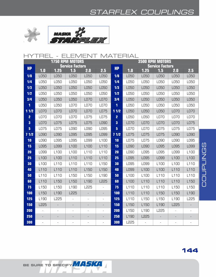
CO
UPLIN
GS
144
STARFLEX COUPLINGS
1750 RPM MOTORS 3500 RPM MOTORS
HP Service Factors HP Service Factors1.0 1.25 1.5 2.0 2.5 1.0 1.25 1.5 2.0 2.5
1/8 L050 L050 L050 L050 L050 1/8 L050 L050 L050 L050 L050
1/4 L050 L050 L050 L050 L050 1/4 L050 L050 L050 L050 L050
1/3 L050 L050 L050 L050 L050 1/3 L050 L050 L050 L050 L050
1/2 L050 L050 L050 L050 L050 1/2 L050 L050 L050 L050 L050
3/4 L050 L050 L050 L070 L070 3/4 L050 L050 L050 L050 L050
1 L050 L050 L070 L070 L070 1 L050 L050 L050 L050 L050
1 1/2 L070 L070 L070 L070 L075 1 1/2 L050 L050 L050 L070 L070
2 L070 L070 L070 L075 L075 2 L050 L050 L070 L070 L070
3 L070 L075 L075 L075 L090 3 L070 L070 L070 L070 L075
5 L075 L075 L090 L090 L095 5 L070 L070 L075 L075 L075
7 1/2 L090 L090 L095 L095 L099 7 1/2 L075 L075 L075 L090 L090
10 L090 L095 L095 L099 L100 10 L075 L075 L090 L090 L095
15 L095 L099 L100 L100 L110 15 L090 L090 L095 L095 L099
20 L099 L100 L100 L110 L110 20 L090 L095 L095 L099 L100
25 L100 L100 L110 L110 L110 25 L095 L095 L099 L100 L100
30 L100 L110 L110 L110 L150 30 L095 L099 L100 L100 L110
40 L110 L110 L110 L150 L150 40 L099 L100 L100 L110 L110
50 L110 L110 L150 L150 L190 50 L100 L100 L110 L110 L110
60 L110 L150 L150 L190 L225 60 L100 L110 L110 L110 L150
75 L150 L150 L190 L225 - 75 L110 L110 L110 L150 L150
100 L150 L190 L225 - - 100 L110 L110 L150 L150 L190
125 L190 L225 - - - 125 L110 L150 L150 L190 L225
150 L225 - - - - 150 L150 L150 L190 L225 -
200 - - - - - 200 L150 L190 L225 - -
250 - - - - - 250 L190 L225 - - -
300 - - - - - 300 L225 - - - -
HYTREL - ELEMENT MATERIAL
BE SURE TO SPECIFY
6-Couplings1.13.qxp 2009-03-19 14:30 Page 21

CO
UPLIN
GS
145
4-FLEX COUPLINGS
4-FLEX: ELASTOMERIC GEAR TYPE COUPLINGS
• Maska 4-Flex part # are based on industry recognized nomenclature
• 4-way flexing action• All types & sizes in cast iron• Precise concentrical product to avoid run-out
and unbalance• No lubrication; smooth, quiet power
transmission• Fast & easy installation; no special tools or
accessories required
DID YOU KNOW THAT...
FLANGEEXAMPLE: 9SX1-9/16
EXAMPLE: 8B-SH
9 X1-1/16
9: 4FLEX FLANGE SIZE
S: 4FLEX FLANGE TYPE
X1-1/16: BORE SIZE (1 1/16")
8: 4FLEX FLANGE SIZE
B: 4FLEX FLANGE TYPE
SH: QD HUB SIZE
HOW TO ORDER
S
8 SHB
ELEMENT MATERIALEXAMPLE: 9JES
9 JES
9: 4FLEX ELEMENT SIZE
JES: ELEMENT MATERIAL AND CONSTRUCTION(EPDM SPLIT - "S" STANDS FOR SPLIT)
NOTE: INSTRUCTIONS ON HOW TO INSTALL INCLUDED WITH EACH FLANGE.
FOR DEPENDABLE DRIVE COMPONENTS, BE SURE TO SPECIFY
6-Couplings1.13.qxp 2009-03-19 14:30 Page 22
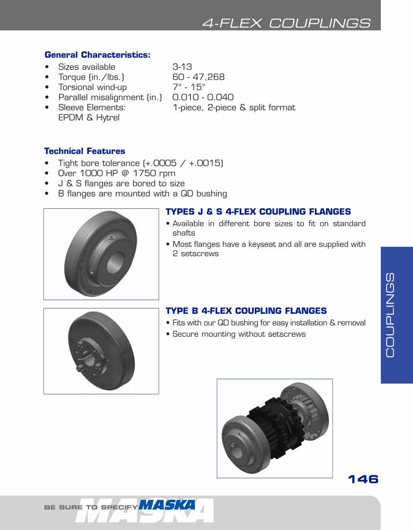
CO
UPLIN
GS
146
4-FLEX COUPLINGS
Technical Features• Tight bore tolerance (+.0005 / +.0015)• Over 1000 HP @ 1750 rpm• J & S flanges are bored to size• B flanges are mounted with a QD bushing
TYPES J & S 4-FLEX COUPLING FLANGES• Available in different bore sizes to fit on standard
shafts• Most flanges have a keyseat and all are supplied with
2 setscrews
TYPE B 4-FLEX COUPLING FLANGES• Fits with our QD bushing for easy installation & removal• Secure mounting without setscrews
General Characteristics:• Sizes available 3-13• Torque (in./lbs.) 60 - 47,268• Torsional wind-up 7° - 15°• Parallel misalignment (in.) 0.010 - 0.040• Sleeve Elements: 1-piece, 2-piece & split format
EPDM & Hytrel
BE SURE TO SPECIFY
6-Couplings1.13.qxp 2009-03-19 14:30 Page 23
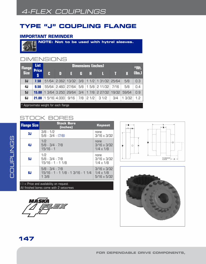
CO
UPLIN
GS
FOR DEPENDABLE DRIVE COMPONENTS, BE SURE TO SPECIFY
147
4-FLEX COUPLINGS
DIMENSIONS
TYPE “J” COUPLING FLANGE
NOTE: Not to be used with hytrel sleeves.IMPORTANT REMINDER
FlangeSize
ListPrice
$
Dimensions (inches) *Wt.(lbs.)C D E G H L T X
3J 7.50 51/64 2.062 13/32 3/8 1 1/2 1 31/32 25/64 5/8 0.3
4J 9.50 55/64 2.460 27/64 5/8 1 5/8 2 11/32 7/16 5/8 0.4
5J 15.00 1 3/64 3.250 29/64 3/4 1 7/8 2 27/32 19/32 59/64 0.9
6J 21.00 1 5/16 4.000 9/16 7/8 2 1/2 3 1/2 3/4 1 3/32 1.2
* Approximate weight for each flange
Flange Size Stock Bore(inches) Keyseat
3J 3/8 - 1/25/8 - 3/4 - (7/8)
none3/16 x 3/32
4J1/25/8 - 3/4 - 7/815/16 - 1
none3/16 x 3/321/4 x 1/8
5J1/25/8 - 3/4 - 7/815/16 - 1 - 1 1/8
none3/16 x 3/321/4 x 1/8
6J5/8 - 3/4 - 7/815/16 - 1 - 1 1/8 - 1 3/16 - 1 1/41 3/8
3/16 x 3/321/4 x 1/85/16 x 5/32
STOCK BORES
( ) = Price and availability on requestAll finished bores come with 2 setscrews
6-Couplings1.13.qxp 2009-03-19 14:30 Page 24

CO
UPLIN
GS
BE SURE TO SPECIFY
148
4-FLEX COUPLINGS
TYPE “S” COUPLING FLANGE
Flange SizeList
Price $Dimensions (inches) *Wt.
(lbs.)C D E G H L T X5S 20.00 1 11/32 3.250 29/64 23/32 1 7/8 2 13/16 19/32 31/32 1.1
6S TYPE16S TYPE26S TYPE3
26.00 1 5/8 4.000 17/32 7/8 2 1/2 3 1/2 25/32 1 3/32 1.9
26.00 1 5/16 4.000 17/32 7/8 2 1/2 3 1/2 25/32 1 3/32 1.8
26.00 1 9/16 4.000 25/32 7/8 2 13/16 4 25/32 1 3/32 1.8
7S 30.00 1 27/32 4.625 11/16 1 2 13/16 3 15/16 25/32 1 5/16 2.6
8S TYPE18S TYPE2
40.00 2 3/32 5.450 3/4 1 1/8 3 1/4 4 7/16 29/32 1 1/2 4.4
40.00 1 15/16 5.450 1 1/32 1 1/8 3 1/4 5 29/32 1 1/2 3.7
9S TYPE19S TYPE2
60.00 2 13/32 6.350 25/32 1 7/16 3 7/8 5 1/16 1 1/32 1 3/4 6.8
60.00 2 9/32 6.350 1 1/4 1 7/16 4 1/8 6 1 1/32 1 3/4 6.2
10S TYPE110S TYPE2
80.00 2 23/32 7.500 13/16 1 5/8 4 3/8 5 11/16 1 7/32 2 10.5
80.00 2 11/16 7.500 1 15/32 1 5/8 4 3/4 7 1 7/32 2 9.8
11S TYPE 111S TYPE 2
128.00 3 7/16 8.625 1 1/8 1 7/8 5 1/4 7 1/8 1 1/2 2 3/8 16.6
128.00 3 1/16 8.625 1 9/16 1 7/8 5 5/8 8 1 1/2 2 3/8 16.4
12S 156.00 4 10.000 1 9/32 2 5/16 5 3/4 8 1/4 1 11/16 2 11/16 26.6
13S 220.00 4 3/8 11.750 1 5/16 2 11/16 6 3/4 9 1/4 1 31/32 3 1/16 45.2
DIMENSIONS
* Approximate weight for each flangeAll finished bores come with 2 set screws.
Note: Can be used with both sleeve types.
6-Couplings1.13.qxp 2009-03-19 14:30 Page 25
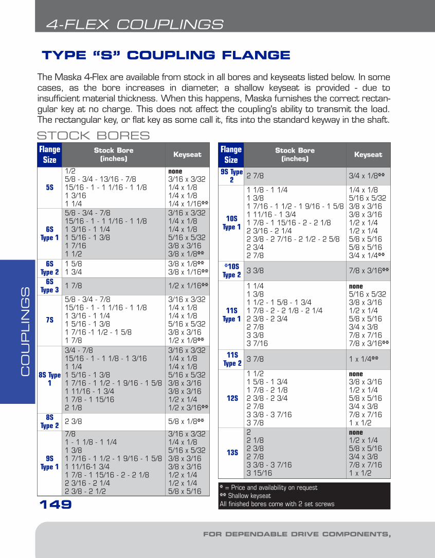
CO
UPLIN
GS
FOR DEPENDABLE DRIVE COMPONENTS, BE SURE TO SPECIFY
4-FLEX COUPLINGS
TYPE “S” COUPLING FLANGE
149
FlangeSize
Stock Bore(inches) Keyseat
5S
1/25/8 - 3/4 - 13/16 - 7/815/16 - 1 - 1 1/16 - 1 1/81 3/161 1/4
none3/16 x 3/321/4 x 1/81/4 x 1/81/4 x 1/16**
6S Type 1
5/8 - 3/4 - 7/8 15/16 - 1 - 1 1/16 - 1 1/81 3/16 - 1 1/41 5/16 - 1 3/8 1 7/16 1 1/2
3/16 x 3/321/4 x 1/81/4 x 1/85/16 x 5/323/8 x 3/163/8 x 1/8**
6S Type 2
1 5/81 3/4
3/8 x 1/8**3/8 x 1/16**
6S Type 3 1 7/8 1/2 x 1/16**
7S
5/8 - 3/4 - 7/8 15/16 - 1 - 1 1/16 - 1 1/81 3/16 - 1 1/41 5/16 - 1 3/8 1 7/16 -1 1/2 - 1 5/81 7/8
3/16 x 3/321/4 x 1/81/4 x 1/85/16 x 5/323/8 x 3/161/2 x 1/8**
8S Type1
3/4 - 7/815/16 - 1 - 1 1/8 - 1 3/161 1/41 5/16 - 1 3/81 7/16 - 1 1/2 - 1 9/16 - 1 5/81 11/16 - 1 3/41 7/8 - 1 15/162 1/8
3/16 x 3/321/4 x 1/81/4 x 1/85/16 x 5/323/8 x 3/163/8 x 3/161/2 x 1/41/2 x 3/16**
8S Type 2 2 3/8 5/8 x 1/8**
9S Type 1
7/81 - 1 1/8 - 1 1/41 3/81 7/16 - 1 1/2 - 1 9/16 - 1 5/81 11/16-1 3/4 1 7/8 - 1 15/16 - 2 - 2 1/82 3/16 - 2 1/42 3/8 - 2 1/2
3/16 x 3/321/4 x 1/85/16 x 5/323/8 x 3/163/8 x 3/161/2 x 1/41/2 x 1/45/8 x 5/16
STOCK BORESFlangeSize
Stock Bore(inches) Keyseat
9S Type2 2 7/8 3/4 x 1/8**
10SType 1
1 1/8 - 1 1/41 3/81 7/16 - 1 1/2 - 1 9/16 - 1 5/81 11/16 - 1 3/41 7/8 - 1 15/16 - 2 - 2 1/82 3/16 - 2 1/42 3/8 - 2 7/16 - 2 1/2 - 2 5/82 3/42 7/8
1/4 x 1/85/16 x 5/323/8 x 3/163/8 x 3/161/2 x 1/41/2 x 1/45/8 x 5/165/8 x 5/163/4 x 1/4**
*10SType 2 3 3/8 7/8 x 3/16**
11SType 1
1 1/41 3/81 1/2 - 1 5/8 - 1 3/41 7/8 - 2 - 2 1/8 - 2 1/4 2 3/8 - 2 3/4 2 7/83 3/83 7/16
none5/16 x 5/323/8 x 3/161/2 x 1/45/8 x 5/163/4 x 3/87/8 x 7/167/8 x 3/16**
11SType 2 3 7/8 1 x 1/4**
12S
1 1/21 5/8 - 1 3/41 7/8 - 2 1/8 2 3/8 - 2 3/4 2 7/83 3/8 - 3 7/163 7/8
none3/8 x 3/161/2 x 1/45/8 x 5/163/4 x 3/87/8 x 7/161 x 1/2
13S
22 1/82 3/82 7/83 3/8 - 3 7/163 15/16
none1/2 x 1/45/8 x 5/163/4 x 3/87/8 x 7/161 x 1/2
The Maska 4-Flex are available from stock in all bores and keyseats listed below. In somecases, as the bore increases in diameter, a shallow keyseat is provided - due to insufficient material thickness. When this happens, Maska furnishes the correct rectan-gular key at no charge. This does not affect the coupling's ability to transmit the load.The rectangular key, or flat key as some call it, fits into the standard keyway in the shaft.
* = Price and availability on request** Shallow keyseatAll finished bores come with 2 set screws
6-Couplings1.13.qxp 2009-03-19 14:30 Page 26

CO
UPLIN
GS
BE SURE TO SPECIFY
150
4-FLEX COUPLINGS
TYPE “B” COUPLING FLANGE
NOTE: Not to be used with hytrelsleeves.
IMPORTANT REMINDER
DIMENSIONSFlangeSize
ListPrice $
Bush.Size
Dimensions (inches) ¬Max.Bore
(inches)
*Wt. (lbs.)
C1 C2 D E F G L T X Flange Bush.
6B 38.00 JA 1 17/64 1 4.000 33/64 2 7/8 3 13/32 3/4 1 3/32 1 1/4 1.4 0.4
7B 44.00 JA 1 19/64 1 4.625 33/64 2 1 3 19/32 25/32 1 5/16 1 1/4 1.9 0.4
8B 50.00 SH 1 31/32 1 1/4 5.450 5/8 2 11/16 1 1/8 4 3/16 29/32 1 1/2 1 5/8 2.9 0.9
9B 62.00 SD 2 5/16 1 13/16 6.350 11/16 3 3/16 1 7/16 4 7/8 1 1/32 1 3/4 1 15/16 4.8 1.6
10B 84.00 SK 2 1/32 1 7/8 7.500 13/16 3 7/8 1 5/8 5 11/16 1 7/32 2 2 1/2 7.8 2.7
11B 120.00 SF 2 5/16 2 8.625 13/16 4 5/8 1 7/8 6 1/2 1 1/2 2 3/8 2 15/16 12.0 3.9
12B 146.00 E 2 29/32 2 5/8 10.000 1 1/8 6 2 5/16 7 15/16 1 11/16 2 11/16 3 1/2 18.0 8.5
13B 208.00 F 3 29/32 3 5/8 11.750 1 7/32 6 5/8 2 11/16 9 1/16 1 31/32 3 3 15/16 31.2 13.3
¬ Maximum bore with keyseat * Approximate weight for each flange
6-Couplings1.13.qxp 2009-03-19 14:30 Page 27
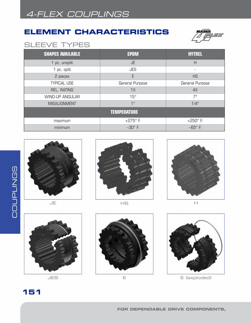
CO
UPLIN
GS
FOR DEPENDABLE DRIVE COMPONENTS, BE SURE TO SPECIFY
151
4-FLEX COUPLINGS
ELEMENT CHARACTERISTICS
JE HS H
JES E E (exploded)
SHAPES AVAILABLE EPDM HYTREL
1 pc, unsplit JE H
1 pc, split JES -
2 pieces E HS
TYPICAL USE General Purpose General Purpose
REL. RATING 1X 4X
WIND-UP ANGULAR 15° 7°
MISALIGNMENT 1° 1/4°
TEMPERATURE
maximum +275° F. +250° F.
minimum –30° F. –65° F.
SLEEVE TYPES
6-Couplings1.13.qxp 2009-03-19 14:30 Page 28

CO
UPLIN
GS
BE SURE TO SPECIFY
152
4-FLEX COUPLINGS
Part #List
Price $Part #
List Price $
CouplingSize
D(inches)
W(inches)
Wt.(lbs)
3JE 4.20 3JES 5.60 3 1 7/8 1 0.064JE 6.00 4JES 8.00 4 2 5/16 1 1/4 0.105JE 12.00 5JES 14.00 5 2 15/16 1 9/16 0.206JE 20.00 6JES 22.00 6 3 3/4 1 7/8 0.407JE 26.00 7JES 28.00 7 4 11/32 2 3/16 0.628JE 34.00 8JES 38.00 8 5 1/16 2 1/2 1.139JE 40.00 9JES 44.00 9 6 3 1.4610JE 56.00 10JES 60.00 10 7 1/16 3 7/16 2.3211E 164.00 --- 11 8 3/16 4 5.1012E 240.00 --- 12 9 9/16 4 11/16 8.1013E 420.00 --- 13 11 3/16 5 1/2 13.00
DIMENSIONS
“B” FLANGES “J”, “S” FLANGES
JE & JES
1. SLEEVE2. FLANGE3. BUSHING
EPDM ELEMENT - TYPES “JE”, “JES”, “E”
E
FlangeSize
EPDMElement
Max.RPM
HP PER 100 RPM
Torque(in. lbs.)
Stiffness(in.
lbs./rad)
E (inches)
Allow.Misalignment
(inches)Service Factor
1.0 1.5 2.0 2.5 3.0 Parallel Angular3 JE, JES 9200 0.1 0.07 0.05 0.04 0.03 60 229 1.188 0.010 0.0354 JE, JES 7600 0.2 0.13 0.10 0.08 0.07 120 458 1.500 0.010 0.0435 JE, JES 7600 0.4 0.27 0.20 0.16 0.13 240 916 1.938 0.015 0.0566 JE, JES 6000 0.7 0.47 0.35 0.28 0.23 450 1718 2.375 0.015 0.0707 JE, JES 5250 1.2 0.80 0.60 0.48 0.40 725 2769 2.563 0.020 0.0818 JE, JES 4500 1.8 1.20 0.90 0.72 0.60 1135 4335 2.938 0.020 0.0949 JE, JES 3750 2.9 1.93 1.45 1.16 0.97 1800 6875 3.500 0.025 0.10910 JE, JES 3600 4.6 3.07 2.30 1.84 1.53 2875 10980 4.063 0.025 0.12811 E 3600 7.2 4.80 3.60 2.88 2.40 4530 17300 4.875 0.032 0.15112 E 2800 11.4 7.60 5.70 4.56 3.80 7200 27500 5.688 0.032 0.17513 E 2400 18.0 12.00 9.00 7.20 6.00 11350 43350 6.625 0.040 0.195
COUPLING RATINGS & MISALIGNMENT
6-Couplings1.13.qxp 2009-03-19 14:30 Page 29
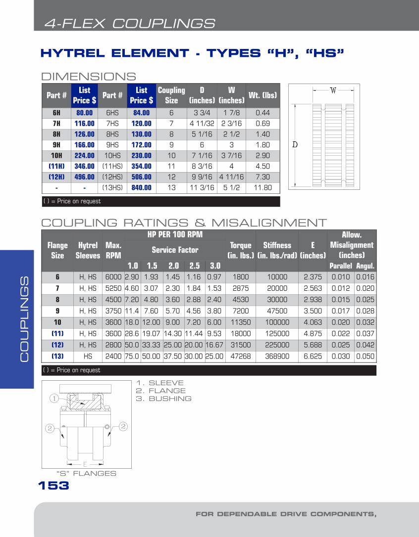
CO
UPLIN
GS
FOR DEPENDABLE DRIVE COMPONENTS, BE SURE TO SPECIFY
153
4-FLEX COUPLINGS
HYTREL ELEMENT - TYPES “H”, “HS”
Part #List
Price $Part #
List Price $
CouplingSize
D(inches)
W(inches)
Wt. (lbs)
6H 80.00 6HS 84.00 6 3 3/4 1 7/8 0.44
7H 116.00 7HS 120.00 7 4 11/32 2 3/16 0.69
8H 126.00 8HS 130.00 8 5 1/16 2 1/2 1.40
9H 166.00 9HS 172.00 9 6 3 1.80
10H 224.00 10HS 230.00 10 7 1/16 3 7/16 2.90
(11H) 346.00 (11HS) 354.00 11 8 3/16 4 4.50
(12H) 496.00 (12HS) 506.00 12 9 9/16 4 11/16 7.30
- - (13HS) 840.00 13 11 3/16 5 1/2 11.80
DIMENSIONS
( ) = Price on request
FlangeSize
HytrelSleeves
Max.RPM
HP PER 100 RPMTorque
(in. lbs.)Stiffness
(in. lbs./rad)E
(inches)
Allow.Misalignment
(inches)Service Factor
1.0 1.5 2.0 2.5 3.0 Parallel Angul.6 H, HS 6000 2.90 1.93 1.45 1.16 0.97 1800 10000 2.375 0.010 0.016
7 H, HS 5250 4.60 3.07 2.30 1.84 1.53 2875 20000 2.563 0.012 0.020
8 H, HS 4500 7.20 4.80 3.60 2.88 2.40 4530 30000 2.938 0.015 0.025
9 H, HS 3750 11.4 7.60 5.70 4.56 3.80 7200 47500 3.500 0.017 0.028
10 H, HS 3600 18.0 12.00 9.00 7.20 6.00 11350 100000 4.063 0.020 0.032
(11) H, HS 3600 28.6 19.07 14.30 11.44 9.53 18000 125000 4.875 0.022 0.037
(12) H, HS 2800 50.0 33.33 25.00 20.00 16.67 31500 225000 5.688 0.025 0.042
(13) HS 2400 75.0 50.00 37.50 30.00 25.00 47268 368900 6.625 0.030 0.050
COUPLING RATINGS & MISALIGNMENT
( ) = Price on request
“S” FLANGES
1. SLEEVE2. FLANGE3. BUSHING
6-Couplings1.13.qxp 2009-03-19 14:30 Page 30

CO
UPLIN
GS
BE SURE TO SPECIFY
154
4-FLEX COUPLINGS
860 RPM MOTORS 1160 RPM MOTORS 1750 RPM MOTORS 3500 RPM MOTORS
HPService Factors
HPService Factors
HPService Factors
HPService Factors
1.0 1.25 1.5 2.0 2.5 1.0 1.25 1.5 2.0 2.5 1.0 1.25 1.5 2.0 2.5 1.0 1.25 1.5 2.0 2.5
1/2 3 3 3 4 4 1/2 3 3 3 3 4 1/2 3 3 3 3 3 1/2 - - - - -
3/4 3 4 4 4 5 3/4 3 3 4 4 4 3/4 3 3 3 3 4 3/4 3 3 3 3 3
1 4 4 4 5 5 1 3 4 4 4 5 1 3 3 3 4 4 1 3 3 3 3 3
1 1/2 4 5 5 5 6 1 1/2 4 4 5 5 5 1 1/2 3 4 4 4 5 1 1/2 3 3 3 3 4
2 5 5 5 6 6 2 4 5 5 5 6 2 4 4 4 5 5 2 3 3 3 4 4
3 5 6 6 6 7 3 5 5 6 6 6 3 4 5 5 5 6 3 3 4 4 4 5
5 6 6 7 7 8 5 6 6 6 7 7 5 5 5 6 6 6 5 4 4 5 5 5
7 1/2 7 7 8 8 9 7 1/2 6 7 7 8 8 7 1/2 6 6 6 7 7 7 1/2 5 5 5 6 6
10 7 8 8 9 9 10 7 7 8 8 9 10 6 6 7 7 8 10 5 5 6 6 6
15 8 9 9 10 10 15 8 8 9 9 10 15 7 7 8 8 9 15 6 6 6 7 7
20 9 9 10 10 11 20 8 9 9 10 10 20 7 8 8 9 9 20 6 6 7 7 8
25 9 10 10 11 11 25 9 9 10 10 11 25 8 8 9 9 10 25 6 7 7 8 8
30 10 10 11 11 12 30 9 10 10 11 11 30 8 9 9 10 10 30 7 7 8 8 9
40 10 11 11 12 12 40 10 10 11 11 12 40 9 9 10 10 11 40 7 8 8 9 9
50 11 11 12 12 13 50 10 11 11 12 12 50 9 10 10 11 11 50 8 8 9 9 10
60 11 12 12 13 13 60 11 11 12 12 13 60 10 10 11 11 12 60 8 9 9 10 10
75 12 12 13 13 - 75 11 12 12 13 13 75 10 11 11 12 12 75 9 9 10 10 11
100 12 13 13 - - 100 12 12 13 13 - 100 11 11 12 12 13 100 9 10 10 11 11
125 13 13 - - - 125 12 13 13 - - 125 11 12 12 13 13 125 10 10 11 11 -
150 13 - - - - 150 13 13 - - - 150 12 12 13 13 - 150 10 11 11 - -
200 - - - - - 200 13 - - - - 200 12 13 13 - - 200 11 11 - - -
250 - - - - - 250 - - - - - 250 13 13 - - - 250 11 - - - -
300 - - - - - 300 - - - - - 300 13 - - - - 300 - - - - -
COUPLING SELECTION - SERVICEFACTORS FOR ELEMENT MATERIALSEPDM - “JE”, “JES”, “E”
6-Couplings1.13.qxp 2009-03-19 14:30 Page 31

CO
UPLIN
GS
FOR DEPENDABLE DRIVE COMPONENTS, BE SURE TO SPECIFY
155
4-FLEX COUPLINGS
860 RPM MOTORS 1160 RPM MOTORS 1750 RPM MOTORS 3500 RPM MOTORS
HPService Factors
HPService Factors
HPService Factors
HPService Factors
1.0 1.25 1.5 2.0 2.5 1.0 1.25 1.5 2.0 2.5 1.0 1.25 1.5 2.0 2.5 1.0 1.25 1.5 2.0 2.5
7 1/2 6 6 6 6 6 7 1/2 - - - - - 7 1/2 - - - - - 7 1/2 - - - - -
10 6 6 6 6 6 10 6 6 6 6 6 10 - - - - - 10 - - - - -
15 6 6 6 7 7 15 6 6 6 6 7 15 6 6 6 6 6 15 - - - - -
20 6 6 7 7 8 20 6 6 6 7 7 20 6 6 6 6 6 20 - - - - -
25 6 7 7 8 8 25 6 6 7 7 8 25 6 6 6 6 7 25 - - - - -
30 7 7 8 8 9 30 6 7 7 8 8 30 6 6 6 7 7 30 6 6 6 6 6
40 7 8 8 9 9 40 7 7 8 8 9 40 6 6 7 7 8 40 6 6 6 6 6
50 8 8 9 9 10 50 7 8 8 9 9 50 6 7 7 8 8 50 6 6 6 6 7
60 8 9 9 10 10 60 8 8 9 9 10 60 7 7 8 8 9 60 6 6 6 7 7
75 9 9 10 10 11 75 8 9 9 10 10 75 7 8 8 9 9 75 6 6 7 7 8
100 9 10 10 11 11 100 9 9 10 10 11 100 8 8 9 9 10 100 6 7 7 8 8
125 10 10 11 11 12 125 9 10 10 11 11 125 8 9 9 10 10 125 7 7 8 8 9
150 10 11 11 12 12 150 10 10 11 11 12 150 9 9 10 10 11 150 7 8 8 9 9
200 11 11 12 12 13 200 10 11 11 12 12 200 9 10 10 11 11 200 8 8 9 9 10
250 11 12 12 13 13 250 11 11 12 12 13 250 10 10 11 11 12 250 8 9 9 10 10
300 12 12 13 13 - 300 11 12 12 13 13 300 10 11 11 12 12 300 9 9 10 10 11
350 12 12 13 - - 350 12 12 12 13 - 350 11 11 12 12 12 350 9 10 10 11 11
400 12 13 13 - - 400 12 12 13 13 - 400 11 11 12 12 13 400 9 10 10 11 11
500 13 13 - - - 500 12 13 13 - - 500 11 12 12 13 13 500 10 10 11 11 -
600 13 - - - - 600 13 13 13 - - 600 12 12 13 13 - 600 10 11 11 - -
700 - - - - - 700 13 13 - - - 700 12 12 13 - - 700 11 11 - - -
800 - - - - - 800 13 - - - - 800 12 13 13 - - 800 11 11 - - -
900 - - - - - 900 - - - - - 900 13 13 - - - 900 11 - - - -
1000 - - - - - 1000 - - - - - 1000 13 13 - - - 1000 11 - - - -
COUPLING SELECTION - SERVICEFACTORS FOR ELEMENT MATERIALSHYTREL - “H”, “HS”
6-Couplings1.13.qxp 2009-03-19 14:30 Page 32

CO
UPLIN
GS
BE SURE TO SPECIFY
156
MASKAFLEX COUPLINGS
• Superior European designed and manufactured“X-Tork” tire
• Bonded and thermally stabilized rubber withdouble-woven textile cords & cord reinforcedbead for greater torque capacity
• Ridged extremity & inner sidewalls designed forenhance grip of the flanges
DID YOU KNOW THAT...
• Maska Flex couplings are balancedto meet general industrial applica-tions. Applications with a speed
superior to 5,000 fts./min. may require more accurate balancing.
• Shaft ends can project beyond the bushing.If this occurs, allow space between shaftends for endfloat & misalignment.
• The standard tire element in natural rubberis designed for temperatures between -42°Cand +82°C.
IMPORTANT REMINDER
MASKAFLEX ELASTOMERIC TIRE TYPE
Most suitable coupling for applications with shockloads, angular misalignment up to 4° and end floatup to ¼".
Fits with our QD bushing for easier installation anddismounting and has greater versatility than thefixed bore style without damaging the shaft.
Important: On-line Ordering Information forMaskaFlex Part Numbers - see page 160.
6-Couplings1.13.qxp 2009-03-19 14:30 Page 33

CO
UPLIN
GS
FOR DEPENDABLE DRIVE COMPONENTS, BE SURE TO SPECIFY
157
MASKAFLEX COUPLINGS
EXAMPLE: MX 120MX 120
MX 120: COMPLETE MASKAFLEX PART NUMBER
HOW TO ORDER
EXAMPLE: MXF 120MXF 120
MXF 120: MASKAFLEX FLANGE PART NUMBER
EXAMPLE: P120P120P120: MASKAFLEX ELEMENT PART NUMBER
(TIRE)A complete Maskaflex coupling corresponds to (2)flanges and (1) element. Specify the bore sizerequired to order the appropriate QD bushing with it.
COMPLETE COUPLING
FLANGE
ELEMENT MATERIAL
MASKAFLEX ELASTOMERIC TIRE TYPE
6-Couplings1.13.qxp 2009-03-19 14:30 Page 34

CO
UPLIN
GS
BE SURE TO SPECIFY
158
MASKAFLEX COUPLINGS
Easy to Assemble
Flexible elastomeric element
MASKA-FLEXMaska
HI-FLEXMaurey
*PARA-FLEXDodge
MARTIN-FLEXMartin
MX50 50JA PX50 F5 JA
MX60 60SH PX60 F6 JA
MX70 70SH PX70 F7 SH
MX80 80SDS PX80 F8 SDS
MX90 90SK PX90 F9 SK
MX100 100SF PX100 F10 SF
MX110 110SF PX110 F11 SF
MX120 120E PX120 F12 E
MX140 140E PX140 N/A
MX160 N/A PX160 N/A
MX200 N/A PX200 N/A
CROSS REFERENCES
* Paraflex Couplings are designed for use with taper-lock bushings.
Coupling No. CAPSCREW TORQUE
MX50 1/4-20UNC x 1 96 in-lbs
MX60 1/4-20UNC x 1-1/4 96 in-lbs
MX70 5/16-18UNC x 1-1/2 205 in-lbs
MX80 5/16-18UNC x 1-1/2 205 in-lbs
MX90 3/8-16 x 1-3/4 360 in-lbs
MX100 3/8-16 x 1-3/4 360 in-lbs
MX110 3/8-16 x 2 360 in-lbs
MX120 1/2-13UNC x 2-1/4 900 in-lbs
MX140 1/2-13UNC x 2-1/2 900 in-lbs
MX160 5/8-11UNC x 3 Grade 8 1800 in-lbs
MX200 5/8-11UNC x 4 Grade 8 1800 in-lbs
WRENCH TORQUE TOTIGHTEN SCREWS
6-Couplings1.13.qxp 2009-03-19 14:30 Page 35
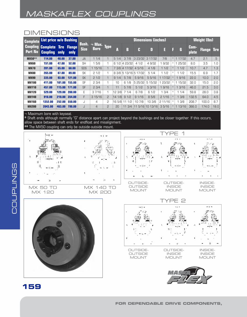
CO
UPLIN
GS
FOR DEPENDABLE DRIVE COMPONENTS, BE SURE TO SPECIFY
159
MASKAFLEX COUPLINGS
DIMENSIONSCompleteCouplingPart No
List price w/o BushingBush.Size
¬ Max.Bore Type
Dimensions (inches) Weight (lbs)
CompleteCoupling
Tireonly
Flangeonly
A B C D E F GCom-plete
Flange Tire
MX50** 114.00 40.00 37.00 JA 1 1/4 1 5 1/4 3 7/8 3 23/32 3 17/32 7/8 * 1 17/32 4.7 2.1 .5
MX60 151.00 47.00 52.00 SH 1 5/8 1 6 1/2 4 23/32 4 1/2 4 9/32 1 9/32 * 1 25/32 8.0 3.5 1.0
MX70 201.00 65.00 68.00 SDS 1 15/16 1 7 3/8 4 17/32 4 5/16 4 1/8 1 1/2 * 1 1/2 10.7 4.7 1.3
MX80 265.00 87.00 89.00 SK 2 1/2 1 8 3/8 5 13/16 5 17/32 5 1/4 1 1/2 * 1 1/2 15.5 6.9 1.7
MX90 335.00 93.00 121.00 SK 2 1/2 1 9 1/4 5 7/8 5 9/16 5 5/16 1 17/32 * 1 9/16 22.0 10.0 2.0
MX100 411.00 101.00 155.00 SF 2 3/4 1 10 6 1/8 5 25/32 5 15/32 1 23/32 * 1 15/32 32.0 15.0 2.0
MX110 457.00 115.00 171.00 SF 2 3/4 1 11 5 7/8 5 1/2 5 3/16 1 9/16 * 1 3/16 46.0 21.5 3.0
MX120 529.00 129.00 200.00 E 3 7/16 1 12 3/8 7 1/4 6 7/8 6 1/2 1 3/4 * 1 1/4 59.8 28.0 3.8
MX140 918.00 210.00 354.00 F 3 15/16 2 14 1/8 9 1/2 9 1/16 8 5/8 2 1/16 * 1 3/8 132.5 64.0 4.5
MX160 1352.00 252.00 550.00 J 4 2 16 5/8 11 1/2 10 7/8 10 3/8 2 11/16 * 1 3/8 208.7 100.0 8.7
MX200 2043.00 463.00 790.00 J 4 2 20 11 3/4 11 5/16 10 13/16 3 5/16 * 1 13/16 366.0 174.0 18.0
OUTSIDE-OUTSIDEMOUNT
TYPE 1
OUTSIDE-INSIDEMOUNT
INSIDE-INSIDEMOUNT
OUTSIDE-OUTSIDEMOUNT
TYPE 2
OUTSIDE-INSIDEMOUNT
INSIDE-INSIDEMOUNT
¬ Maximum bore with keyseat * Shaft ends although normally “G” distance apart can project beyond the bushings and be closer together. If this occurs,allow space between shaft ends for endfloat and misalignment.** The MX50 coupling can only be outside-outside mount.
MX 50 TOMX 120
MX 140 TOMX 200
6-Couplings1.13.qxp 2009-03-19 14:30 Page 36
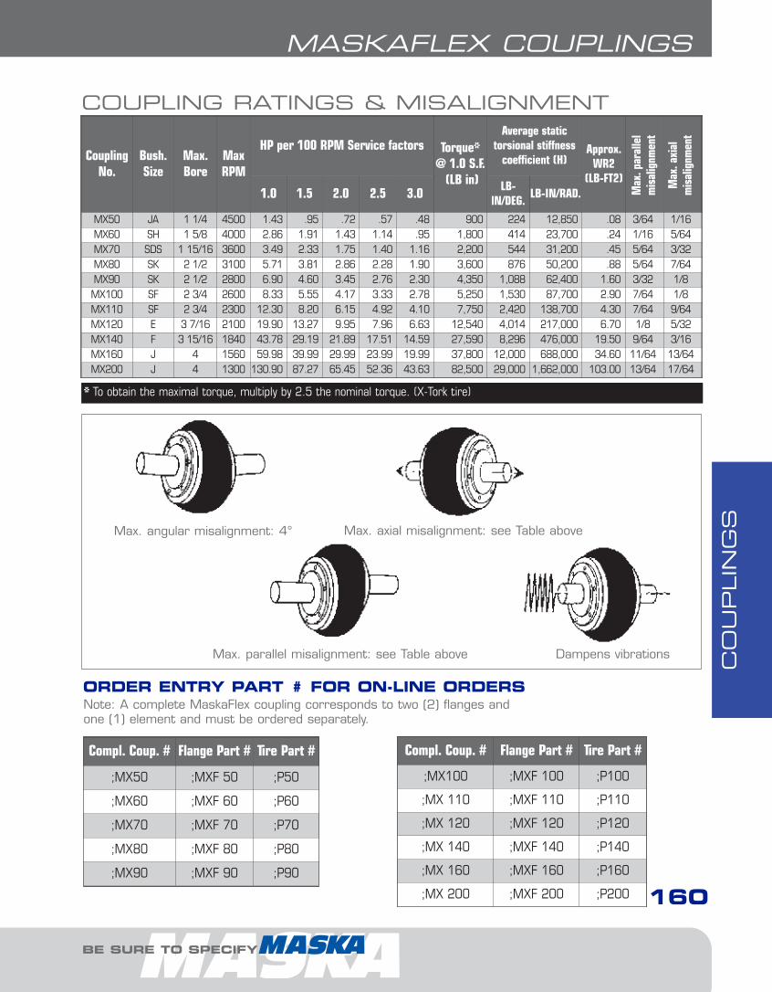
CO
UPLIN
GS
BE SURE TO SPECIFY
MASKAFLEX COUPLINGS
Compl. Coup. # Flange Part # Tire Part #
;MX50 ;MXF 50 ;P50
;MX60 ;MXF 60 ;P60
;MX70 ;MXF 70 ;P70
;MX80 ;MXF 80 ;P80
;MX90 ;MXF 90 ;P90
Compl. Coup. # Flange Part # Tire Part #
;MX100 ;MXF 100 ;P100
;MX 110 ;MXF 110 ;P110
;MX 120 ;MXF 120 ;P120
;MX 140 ;MXF 140 ;P140
;MX 160 ;MXF 160 ;P160
;MX 200 ;MXF 200 ;P200
ORDER ENTRY PART # FOR ON-LINE ORDERS
COUPLING RATINGS & MISALIGNMENT
CouplingNo.
Bush.Size
Max.Bore
MaxRPM
HP per 100 RPM Service factors Torque* @ 1.0 S.F.
(LB in)
Average static torsional stiffness
coefficient (H)Approx.
WR2(LB-FT2)
1.0 1.5 2.0 2.5 3.0 LB-lN/DEG.
LB-IN/RAD.
MX50 JA 1 1/4 4500 1.43 .95 .72 .57 .48 900 224 12,850 .08 3/64 1/16MX60 SH 1 5/8 4000 2.86 1.91 1.43 1.14 .95 1,800 414 23,700 .24 1/16 5/64MX70 SDS 1 15/16 3600 3.49 2.33 1.75 1.40 1.16 2,200 544 31,200 .45 5/64 3/32MX80 SK 2 1/2 3100 5.71 3.81 2.86 2.28 1.90 3,600 876 50,200 .88 5/64 7/64MX90 SK 2 1/2 2800 6.90 4.60 3.45 2.76 2.30 4,350 1,088 62,400 1.60 3/32 1/8MX100 SF 2 3/4 2600 8.33 5.55 4.17 3.33 2.78 5,250 1,530 87,700 2.90 7/64 1/8MX110 SF 2 3/4 2300 12.30 8.20 6.15 4.92 4.10 7,750 2,420 138,700 4.30 7/64 9/64MX120 E 3 7/16 2100 19.90 13.27 9.95 7.96 6.63 12,540 4,014 217,000 6.70 1/8 5/32MX140 F 3 15/16 1840 43.78 29.19 21.89 17.51 14.59 27,590 8,296 476,000 19.50 9/64 3/16MX160 J 4 1560 59.98 39.99 29.99 23.99 19.99 37,800 12,000 688,000 34.60 11/64 13/64MX200 J 4 1300 130.90 87.27 65.45 52.36 43.63 82,500 29,000 1,662,000 103.00 13/64 17/64
* To obtain the maximal torque, multiply by 2.5 the nominal torque. (X-Tork tire)
Max. angular misalignment: 4° Max. axial misalignment: see Table above
Max. parallel misalignment: see Table above Dampens vibrations
Max
. par
alle
l m
isal
ignm
ent
Max
. axi
alm
isal
ignm
ent
Note: A complete MaskaFlex coupling corresponds to two (2) flanges and one (1) element and must be ordered separately.
160
6-Couplings1.13.qxp 2009-03-19 14:30 Page 37
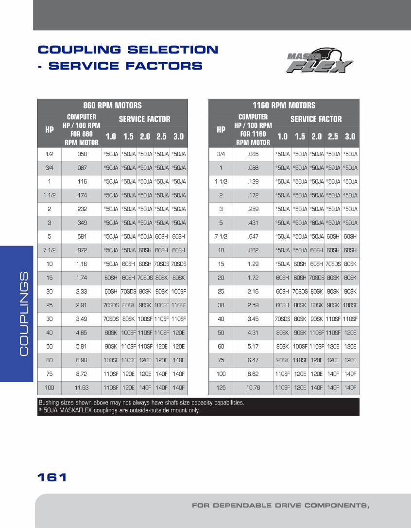
MASKAFLEX COUPLINGSC
OU
PLIN
GS
FOR DEPENDABLE DRIVE COMPONENTS, BE SURE TO SPECIFY
161
860 RPM MOTORS
HP
COMPUTERHP / 100 RPM
FOR 860RPM MOTOR
SERVICE FACTOR
1.0 1.5 2.0 2.5 3.0
1/2 .058 *50JA *50JA *50JA *50JA *50JA
3/4 .087 *50JA *50JA *50JA *50JA *50JA
1 .116 *50JA *50JA *50JA *50JA *50JA
1 1/2 .174 *50JA *50JA *50JA *50JA *50JA
2 .232 *50JA *50JA *50JA *50JA *50JA
3 .349 *50JA *50JA *50JA *50JA *50JA
5 .581 *50JA *50JA *50JA 60SH 60SH
7 1/2 .872 *50JA *50JA 60SH 60SH 60SH
10 1.16 *50JA 60SH 60SH 70SDS 70SDS
15 1.74 60SH 60SH 70SDS 80SK 80SK
20 2.33 60SH 70SDS 80SK 90SK 100SF
25 2.91 70SDS 80SK 90SK 100SF 110SF
30 3.49 70SDS 80SK 100SF 110SF 110SF
40 4.65 80SK 100SF 110SF 110SF 120E
50 5.81 90SK 110SF 110SF 120E 120E
60 6.98 100SF 110SF 120E 120E 140F
75 8.72 110SF 120E 120E 140F 140F
100 11.63 110SF 120E 140F 140F 140F
1160 RPM MOTORS
HP
COMPUTERHP / 100 RPM
FOR 1160RPM MOTOR
SERVICE FACTOR
1.0 1.5 2.0 2.5 3.0
3/4 .065 *50JA *50JA *50JA *50JA *50JA
1 .086 *50JA *50JA *50JA *50JA *50JA
1 1/2 .129 *50JA *50JA *50JA *50JA *50JA
2 .172 *50JA *50JA *50JA *50JA *50JA
3 .259 *50JA *50JA *50JA *50JA *50JA
5 .431 *50JA *50JA *60JA *50JA *50JA
7 1/2 .647 *50JA *50JA *50JA 60SH 60SH
10 .862 *50JA *50JA 60SH 60SH 60SH
15 1.29 *50JA 60SH 60SH 70SDS 80SK
20 1.72 60SH 60SH 70SDS 80SK 80SK
25 2.16 60SH 70SDS 80SK 80SK 90SK
30 2.59 60SH 80SK 80SK 90SK 100SF
40 3.45 70SDS 80SK 90SK 110SF 110SF
50 4.31 80SK 90SK 110SF 110SF 120E
60 5.17 80SK 100SF 110SF 120E 120E
75 6.47 90SK 110SF 120E 120E 120E
100 8.62 110SF 120E 120E 140F 140F
125 10.78 110SF 120E 140F 140F 140F
Bushing sizes shown above may not always have shaft size capacity capabilities.* 50JA MASKAFLEX couplings are outside-outside mount only.
COUPLING SELECTION - SERVICE FACTORS
6-Couplings1.13.qxp 2009-03-19 14:30 Page 38

CO
UPLIN
GS
MASKAFLEX COUPLINGS
BE SURE TO SPECIFY
162
1750 RPM MOTORS
HP
COMPUTERHP / 100 RPM
FOR 1750RPM MOTOR
SERVICE FACTOR
1.0 1.5 2.0 2.5 3.0
1 .057 *50JA *50JA *50JA *50JA *50JA
1 1/2 .086 *50JA *50JA *50JA *50JA *50JA
2 .114 *50JA *50JA *50JA *50JA *50JA
3 .171 *50JA *50JA *50JA *50JA *50JA
5 .286 *50JA *50JA *50JA *50JA *50JA
7 1/2 .429 *50JA *50JA *50JA *50JA *50JA
10 .571 *50JA *50JA *50JA *50JA *50JA
15 .857 *50JA *50JA 60SH 60SH 60SH
20 1.14 *50JA 60SH 60SH 60SH 70SDS
25 1.43 *50JA 60SH 60SH 80SK 80SK
30 1.71 60SH 60SH 70SDS 80SK 80SK
40 2.28 60SH 70SDS 80SK 80SK 90SK
50 2.86 60SH 80SK 80SK 100SF 110SF
60 3.43 70SDS 80SK 90SK 110SF 110SF
75 4.28 80SK 90SK 110SF 110SF 120E
100 5.71 80SK 110SF 110SF 120E 120E
125 7.14 100SF 110SF 120E 120E 140F
150 8.57 110SF 120E 120E 140F 140F
200 11.43 110SF 120E 140F 140F 140F
3500 RPM MOTORS
HP
COMPUTERHP / 100 RPM
FOR 3500RPM MOTOR
SERVICE FACTOR
1.0 1.5 2.0 2.5 3.0
1 1/2 .044 *50JA *50JA *50JA *50JA *50JA
2 .057 *50JA *50JA *50JA *50JA *50JA
3 .086 *50JA *50JA *50JA *50JA *50JA
5 .143 *50JA *50JA *50JA *50JA *50JA
7 1/2 .214 *50JA *50JA *50JA *50JA *50JA
10 .286 *50JA *50JA *50JA *50JA *50JA
15 .429 *50JA *50JA *50JA *50JA *50JA
20 .571 *50JA *50JA *50JA *50JA 60SH
25 .714 *50JA *50JA *50JA 60SH 60SH
30 .857 *50JA *50JA 60SH 60SH 60SH
40 1.14 *50JA 60SH 60SH 70SDS 70SDS
50 1.428 *50JA 60SH 60SH -- --
60 1.71 60SH 60SH 70SDS -- --
75 2.14 60SH 70SDS -- -- --
100 2.86 60SH -- -- -- --
125 -- -- -- -- --
150 -- -- -- -- --
200 -- -- -- -- --
250 -- -- -- -- --
Bushing sizes shown above may not always have shaft size capacity capabilities.* 50JA MASKAFLEX couplings are outside-outside mount only.
6-Couplings1.13.qxp 2009-03-19 14:30 Page 39
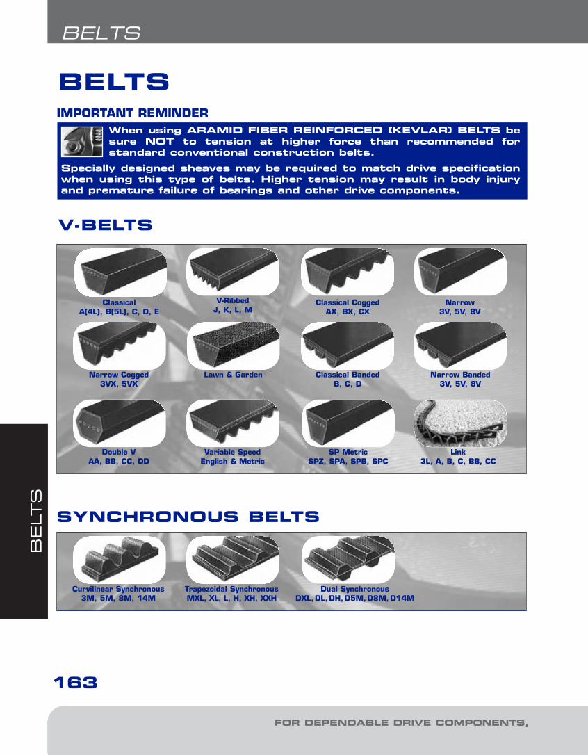
BELT
S
FOR DEPENDABLE DRIVE COMPONENTS, BE SURE TO SPECIFY
163
BELTS
V-BELTS
SYNCHRONOUS BELTS
ClassicalA(4L), B(5L), C, D, E
Classical CoggedAX, BX, CX
Narrow3V, 5V, 8V
Narrow Cogged3VX, 5VX
Lawn & Garden Classical BandedB, C, D
Narrow Banded3V, 5V, 8V
Double VAA, BB, CC, DD
Variable SpeedEnglish & Metric
SP MetricSPZ, SPA, SPB, SPC
V-RibbedJ, K, L, M
Curvilinear Synchronous3M, 5M, 8M, 14M
Trapezoidal SynchronousMXL, XL, L, H, XH, XXH
Dual SynchronousDXL,DL,DH,D5M,D8M,D14M
Link3L, A, B, C, BB, CC
When using ARAMID FIBER REINFORCED (KEVLAR) BELTS besure NOT to tension at higher force than recommended for standard conventional construction belts.
Specially designed sheaves may be required to match drive specificationwhen using this type of belts. Higher tension may result in body injuryand premature failure of bearings and other drive components.
IMPORTANT REMINDER
BELTS
7-Belts1.7.qxp 2009-03-19 14:34 Page 2

BELT
S
BE SURE TO SPECIFY
164
BELTS
BELT TENSIONINGINSTRUCTIONSV-Belts
V-belt tensioning adjustment can be made using a tensionmeter or other type spring scale,using the following procedure. After seating the belts in the groove and adjusting centerdistance so as to take up slack in the belts, further increase the tension until only a slightbow on the slack side is apparent while the drive is operating under load. Stop the drive,and using the meter, measure the force necessary to depress one of the center belts 1/64-inch for every inch of belt span (see sketch below). For example, adeflection for a 50-inch belt span is 50/64ths, or 25/32-inch. The amount of forcerequired to deflect the belt should compare with the deflection forces noted in the chartbelow. Also notice for V-belts that deflection forces vary from the initial “run-in” valueswhich are greater (reflecting higher run-in tensioning) to the “normal” values for after therun-in period.
Synchronous BeltsHign torque, Standard and Metric synchronous belts should be installed to fit pulleys snugly, neither too tight nor too loose. The belt’s positive grip eliminates the need for high initial tension. When a belt is installed with a snug but not overly tight fit, longer belt life,less bearing wear and more quiet operation will result. Overtight belts can cause earlyfailure and should be avoided. With high torque a loose belt may “jump teeth” upon startup. If such occurs, the tension should be increased gradually until satisfactory operation is achieved.
To properly tension a synchronous belt, place belt on pulleys and adjust takeup until thebelt teeth mesh securely with the pulley grooves. Measure belt span “T”. Then tightenbelt so that it deflects 1/64-inch for every inch of belt span when a force as specified inthe table below is applied to the top of the belt. For belts wider than two inches, a metalor wooden strip 3/4 to 1-inch wide should be placed across the belt between it and thetester to prevent distortion.
The following range of deflection forces are normally adequate for drive installation. Actualinstallation tension required depends on peak loads, system rigidity, number of teeth inmesh, etc.
MEASURE THE SPAN LENGTH "T"AS SHOWN IN THE SKETCH ABOVE.
7-Belts1.7.qxp 2009-03-19 14:34 Page 3
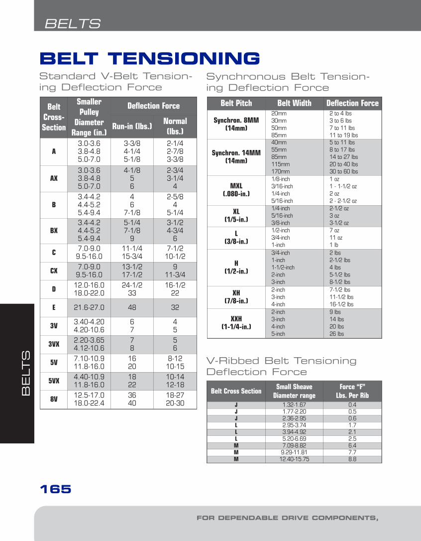
BELT
S
165
BELTS
FOR DEPENDABLE DRIVE COMPONENTS, BE SURE TO SPECIFY
BELT TENSIONING
Belt Pitch Belt Width Deflection Force
Synchron. 8MM(14mm)
20mm30mm50mm85mm
2 to 4 lbs3 to 6 lbs7 to 11 lbs11 to 19 lbs
Synchron. 14MM(14mm)
40mm55mm85mm115mm170mm
5 to 11 lbs8 to 17 lbs14 to 27 lbs20 to 40 lbs30 to 60 lbs
MXL(.080-in.)
1/8-inch3/16-inch1/4-inch5/16-inch
1 oz1 - 1-1/2 oz2 oz2 - 2-1/2 oz
XL(1/5-in.)
1/4-inch5/16-inch3/8-inch
2-1/2 oz3 oz3-1/2 oz
L(3/8-in.)
1/2-inch3/4-inch1-inch
7 oz11 oz1 lb
H(1/2-in.)
3/4-inch1-inch1-1/2-inch2-inch3-inch
2 lbs2-1/2 lbs4 lbs5-1/2 lbs8-1/2 lbs
XH(7/8-in.)
2-inch3-inch4-inch
7-1/2 lbs11-1/2 lbs16-1/2 lbs
XXH(1-1/4-in.)
2-inch3-inch4-inch5-inch
9 lbs14 lbs20 lbs26 lbs
Belt Cross SectionSmall Sheave
Diameter rangeForce “F”
Lbs. Per RibJ 1.32-1.67 0.4J 1.77-2.20 0.5J 2.36-2.95 0.6L 2.95-3.74 1.7L 3.94-4.92 2.1L 5.20-6.69 2.5M 7.09-8.82 6.4M 9.29-11.81 7.7M 12.40-15.75 8.8
BeltCross-Section
SmallerPulley
DiameterRange (in.)
Deflection Force
Run-in (lbs.)Normal(lbs.)
A3.0-3.63.8-4.85.0-7.0
3-3/84-1/45-1/8
2-1/42-7/83-3/8
AX3.0-3.63.8-4.85.0-7.0
4-1/856
2-3/43-1/4
4
B3.4-4.24.4-5.25.4-9.4
46
7-1/8
2-5/84
5-1/4
BX3.4-4.24.4-5.25.4-9.4
5-1/47-1/8
9
3-1/24-3/4
6
C 7.0-9.09.5-16.0
11-1/415-3/4
7-1/210-1/2
CX 7.0-9.09.5-16.0
13-1/217-1/2
911-3/4
D 12.0-16.018.0-22.0
24-1/233
16-1/222
E 21.6-27.0 48 32
3V 3.40-4.204.20-10.6
67
45
3VX 2.20-3.654.12-10.6
78
56
5V 7.10-10.911.8-16.0
1620
8-1210-15
5VX 4.40-10.911.8-16.0
1822
10-1412-18
8V 12.5-17.018.0-22.4
3640
18-2720-30
V-Ribbed Belt TensioningDeflection Force
Standard V-Belt Tension-ing Deflection Force
Synchronous Belt Tension-ing Deflection Force
7-Belts1.7.qxp 2009-03-19 14:34 Page 4

BELT
S
166
BELTS
BE SURE TO SPECIFY
V-BELT DIMENSIONS
7-Belts1.7.qxp 2009-03-19 14:34 Page 5

BELT
S
167
BELTS
FOR DEPENDABLE DRIVE COMPONENTS, BE SURE TO SPECIFY
EXAMPLE: VBB150 & VBB-LINK
VB B
VB: V-BELTB: BELT SECTION ("B" CLASSICAL)150: BELT NUMBER
HOW TO ORDER
150
V-BELTS
CLASSICAL BELTS: The belt number corresponds to the belt inside length. To determine the belt outside length for:
A-AX Sections: Up to belt number 210, add 2 to obtain outside length in inches.
B-BX Sections: Up to belt number 210, add 3 to obtain outside length in inches.
C-CX Sections: Up to belt number 210, add 4 to obtain outside length in inches.
D Section: Up to belt number 210, add 5 to obtain outside length in inches.
NARROW BELTS: Divide the belt number by 10 to obtain the belt outside length.
LINK: LINK BELTS
Sold in standard length of 25 feet.
- 4L & 5L FHP belts can be crossed over to “A” & “B” classicalV-belts. Refer to the following tables for cross references.
- Maska does not recommend the use of two (2) or more 4L or5L belts on the same drive as their length may not match perfectly.
IMPORTANT REMINDER
7-Belts1.7.qxp 2009-03-19 14:34 Page 6

BELT
S
168
CLASSICAL V-BELTS
BE SURE TO SPECIFY
BeltNo.
CrossRef.
ListPrice
$
Approx.Weight(lbs)
A63 4L650 17.60 .30A64 4L660 17.84 .30A65 4L670 18.00 .30A66 4L680 18.00 .40A67 4L690 18.24 .40A68 4L700 18.40 .40A69 4L710 19.20 .40A70 4L720 19.20 .40A71 4L730 19.28 .40A72 4L740 19.44 .40A73 4L750 19.60 .40A74 4L760 19.76 .40A75 4L770 20.00 .40A76 4L780 20.32 .40A77 4L790 20.48 .40A78 4L800 20.80 .40A79 4L810 21.20 .40A80 4L820 21.60 .40A81 4L830 22.00 .40A82 4L840 22.24 .40A83 4L850 22.56 .40A84 4L860 22.80 .40A85 4L870 23.20 .40A86 4L880 23.52 .40A87 4L890 23.84 .40A88 4L900 24.16 .40A89 4L910 24.24 .40A90 4L920 24.80 .40A91 4L930 25.12 .50A92 4L940 25.36 .50A93 4L950 25.60 .50A94 4L960 25.92 .50A95 4L970 26.16 .50A96 4L980 26.40 .50A97 4L990 26.72 .50A98 4L1000 27.04 .50A99 4L1010 27.28 .50A100 4L1020 27.52 .50A101 27.76 .50A102 28.00 .50A103 28.28 .50A104 28.56 .50A105 28.80 .50A106 29.60 .55A107 30.00 .60A108 30.40 .60
(A109) 30.80 .65
BeltNo.
CrossRef.
ListPrice
$
Approx.Weight(lbs)
A110 31.20 .70(A111) 31.60 .75A112 32.00 .80
(A113) 32.32 .80A114 32.64 .80A115 32.96 .80A116 33.28 .80A118 33.92 .80
(A119) 34.16 .80A120 34.40 .80A124 35.60 .80
(A125) 35.90 .80A128 36.80 .80A130 37.36 .80
(A132) 37.88 .80(A133) 38.14 .80A134 38.40 .80
(A135) 38.62 .90A136 38.88 .90
(A137) 39.16 .90(A140) 40.00 .95A144 41.12 1.00
(A148) 42.30 1.02(A152) 43.46 1.05A156 44.62 1.10
(A157) 44.90 1.10A158 45.20 1.10
(A160) 45.60 1.10(A162) 46.00 1.10(A167) 46.90 1.13A173 48.00 1.15A180 49.20 1.15
(A187) 50.00 1.22(A196) 51.00 1.31(A197) 53.00 1.31(A210) 53.80 1.32A221 59.46 1.40
(A256) 68.88 1.60(A258) 69.42 1.60
BeltNo.
CrossRef.
ListPrice
$
Approx.Weight(lbs)
A18 10.00 .10A19 4L210 10.00 .10A20 4L220 10.00 .10A21 4L230 10.16 .10A22 4L240 10.16 .15A23 4L250 10.24 .20A24 4L260 10.32 .20A25 4L270 10.40 .20A26 4L280 10.40 .20A27 4L290 10.56 .20A28 4L300 10.80 .20A29 4L310 10.96 .20A30 4L320 11.20 .20A31 4L330 11.20 .20A32 4L340 11.36 .20A33 4L350 11.60 .20A34 4L360 11.76 .20A35 4L370 12.00 .20A36 4L380 12.00 .20A37 4L390 12.00 .20A38 4L400 12.80 .20A39 4L410 13.28 .20A40 4L420 13.36 .20A41 4L430 13.44 .20A42 4L440 13.60 .20A43 4L450 14.00 .30A44 4L460 14.08 .30A45 4L470 14.24 .30A46 4L480 14.40 .30A47 4L490 14.64 .30A48 4L500 14.80 .30A49 4L510 14.96 .30A50 4L520 15.04 .30A51 4L530 15.20 .30A52 4L540 15.28 .30A53 4L550 15.60 .30A54 4L560 16.00 .30A55 4L570 16.00 .30A56 4L580 16.40 .30A57 4L590 16.48 .30A58 4L600 16.56 .30A59 4L610 16.64 .30A60 4L620 16.80 .30A61 4L630 17.04 .30A62 4L640 17.20 .30
“A” SECTION(1/2-INCH TOP WIDTH, 5/16-INCH THICK)
( ) = Not in stock. Contact Maska forprice and delivery.
CLASSICAL V-BELTS
7-Belts1.7.qxp 2009-03-19 14:34 Page 7

BELT
S
FOR DEPENDABLE DRIVE COMPONENTS, BE SURE TO SPECIFY
CLASSICAL V-BELTS
169
BeltNo.
CrossRef.
ListPrice
$
Approx.Weight(lbs)
B65 5L680 25.28 .70B66 5L690 25.92 .70B67 5L700 26.16 .70B68 5L710 26.40 .70B69 5L720 27.52 .70B70 5L730 28.00 .70B71 5L740 28.16 .70B72 5L750 28.40 .70B73 5L760 28.56 .70B74 5L770 28.72 .70B75 5L780 28.80 .70B76 5L790 29.44 .70B77 5L800 29.92 .80B78 5L810 30.00 .80B79 5L820 30.48 .80B80 5L830 30.96 .80B81 5L840 31.20 .80B82 5L850 31.60 .80B83 5L860 32.24 .80B84 5L870 32.40 .80B85 5L880 32.80 .80B86 5L890 33.12 .80B87 5L900 33.44 .80B88 5L910 33.76 .80B89 5L920 34.08 .80B90 5L930 34.40 .90B91 5L940 34.72 .90B92 5L950 35.04 .90B93 5L960 35.36 .90B94 5L970 35.76 .90B95 5L980 36.08 .90B96 5L990 36.40 .90B97 5L1000 37.60 .90B98 5L1010 37.84 .90B99 5L1020 38.32 1.00B100 38.32 1.00B101 38.56 1.00B102 38.80 1.00B103 38.96 1.00B104 39.20 1.00B105 40.00 1.00B106 40.80 1.00B107 41.20 1.00B108 41.36 1.00B109 41.84 1.10
BeltNo.
ListPrice
$
Approx.Weight(lbs)
B110 42.32 1.10B111 42.76 1.10B112 43.20 1.10B113 43.60 1.20B114 44.00 1.20B115 44.16 1.20B116 44.40 1.20
(B117) 44.72 1.20B118 45.04 1.20B119 45.32 1.20B120 45.60 1.20B122 46.40 1.20B124 47.20 1.20B125 47.60 1.20B126 48.00 1.20B127 48.40 1.20B128 48.80 1.30B130 49.28 1.30B131 49.52 1.30B132 49.76 1.30B133 50.00 1.30B134 50.16 1.30B135 50.40 1.30B136 51.20 1.30B138 52.20 1.30B140 53.20 1.40B141 53.70 1.40
(B142) 54.20 1.40(B143) 54.70 1.40B144 55.20 1.40B146 56.00 1.40B147 56.40 1.40B148 56.80 1.40
(B149) 57.04 1.50B150 57.28 1.50B151 57.64 1.50B152 58.00 1.50B153 58.32 1.50B154 58.64 1.50
(B155) 59.00 1.50B156 59.34 1.50B157 59.68 1.50B158 60.00 1.50B160 60.80 1.50
(B161) 61.20 1.50
BeltNo.
CrossRef.
ListPrice
$
Approx.Weight(lbs)
(B20) 14.00 .40(B21) 14.00 .40B22 5L250 14.00 .40B23 5L260 14.00 .40B24 5L270 14.40 .40B25 5L280 14.80 .40B26 5L290 15.04 .40B27 5L300 15.12 .40B28 5L310 15.20 .40B29 5L320 15.36 .40B30 5L330 15.44 .40B31 5L340 15.60 .40B32 5L350 15.68 .40B33 5L360 15.92 .40B34 5L370 15.92 .40B35 5L380 16.00 .40B36 5L390 16.40 .40B37 5L400 17.20 .40B38 5L410 17.60 .40B39 5L420 18.16 .40B40 5L430 18.32 .40B41 5L440 18.40 .40B42 5L450 19.20 .40B43 5L460 19.44 .40B44 5L470 19.44 .40B45 5L480 20.00 .40B46 5L490 20.80 .50B47 5L500 20.92 .50B48 5L510 21.60 .50B49 5L520 21.76 .50B50 5L530 22.00 .50B51 5L540 22.40 .50B52 5L550 22.48 .50B53 5L560 22.80 .50B54 5L570 23.04 .50B55 5L580 23.20 .60B56 5L590 23.36 .60B57 5L600 23.44 .60B58 5L610 23.52 .60B59 5L620 23.92 .60B60 5L630 24.00 .60B61 5L640 24.40 .70B62 5L650 24.80 .70B63 5L660 24.96 .70B64 5L670 25.12 .70
“B” SECTION(21/32-INCH TOP WIDTH, 13/32-INCH THICK)
( ) = Not in stock. Contact Maska for price and delivery.
7-Belts1.7.qxp 2009-03-19 14:34 Page 8
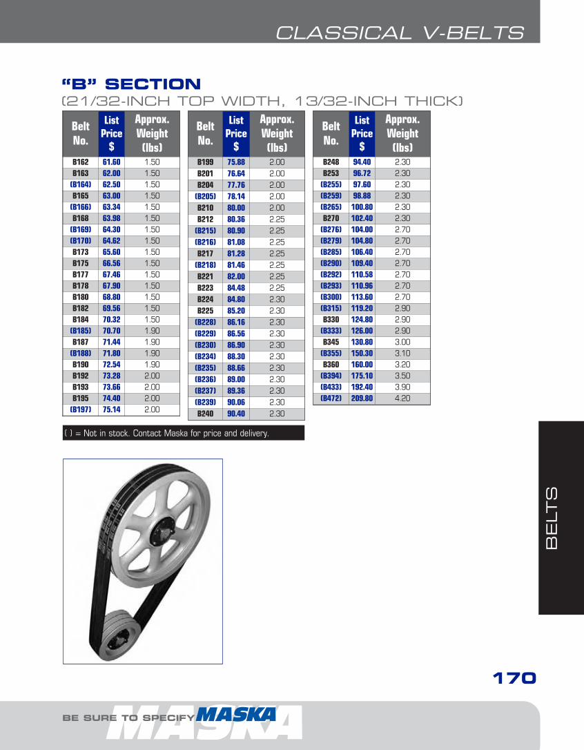
BELT
S
BE SURE TO SPECIFY
CLASSICAL V-BELTS
170
BeltNo.
ListPrice
$
Approx.Weight(lbs)
B162 61.60 1.50B163 62.00 1.50
(B164) 62.50 1.50B165 63.00 1.50
(B166) 63.34 1.50B168 63.98 1.50
(B169) 64.30 1.50(B170) 64.62 1.50B173 65.60 1.50B175 66.56 1.50B177 67.46 1.50B178 67.90 1.50B180 68.80 1.50B182 69.56 1.50B184 70.32 1.50
(B185) 70.70 1.90B187 71.44 1.90
(B188) 71.80 1.90B190 72.54 1.90B192 73.28 2.00B193 73.66 2.00B195 74.40 2.00
(B197) 75.14 2.00
“B” SECTION(21/32-INCH TOP WIDTH, 13/32-INCH THICK)
BeltNo.
ListPrice
$
Approx.Weight(lbs)
B248 94.40 2.30B253 96.72 2.30
(B255) 97.60 2.30(B259) 98.88 2.30(B265) 100.80 2.30B270 102.40 2.30
(B276) 104.00 2.70(B279) 104.80 2.70(B285) 106.40 2.70(B290) 109.40 2.70(B292) 110.58 2.70(B293) 110.96 2.70(B300) 113.60 2.70(B315) 119.20 2.90B330 124.80 2.90
(B333) 126.00 2.90B345 130.80 3.00
(B355) 150.30 3.10B360 160.00 3.20
(B394) 175.10 3.50(B433) 192.40 3.90(B472) 209.80 4.20
BeltNo.
ListPrice
$
Approx.Weight(lbs)
B199 75.88 2.00B201 76.64 2.00B204 77.76 2.00
(B205) 78.14 2.00B210 80.00 2.00B212 80.36 2.25
(B215) 80.90 2.25(B216) 81.08 2.25B217 81.28 2.25
(B218) 81.46 2.25B221 82.00 2.25B223 84.48 2.25B224 84.80 2.30B225 85.20 2.30
(B228) 86.16 2.30(B229) 86.56 2.30(B230) 86.90 2.30(B234) 88.30 2.30(B235) 88.66 2.30(B236) 89.00 2.30(B237) 89.36 2.30(B239) 90.06 2.30B240 90.40 2.30
( ) = Not in stock. Contact Maska for price and delivery.
7-Belts1.7.qxp 2009-03-19 14:34 Page 9
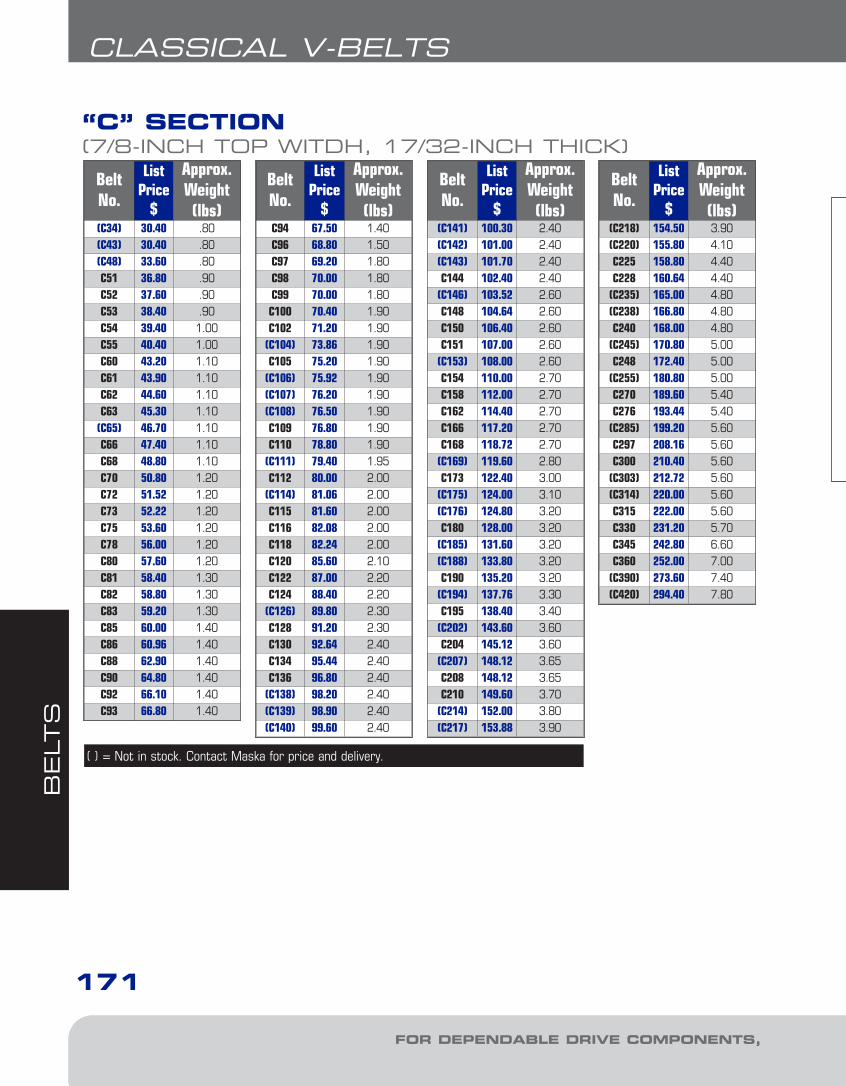
BELT
S
FOR DEPENDABLE DRIVE COMPONENTS, BE SURE TO SPECIFY
CLASSICAL V-BELTS
171
BeltNo.
ListPrice
$
Approx.Weight(lbs)
(C34) 30.40 .80(C43) 30.40 .80(C48) 33.60 .80C51 36.80 .90C52 37.60 .90C53 38.40 .90C54 39.40 1.00C55 40.40 1.00C60 43.20 1.10C61 43.90 1.10C62 44.60 1.10C63 45.30 1.10
(C65) 46.70 1.10C66 47.40 1.10C68 48.80 1.10C70 50.80 1.20C72 51.52 1.20C73 52.22 1.20C75 53.60 1.20C78 56.00 1.20C80 57.60 1.20C81 58.40 1.30C82 58.80 1.30C83 59.20 1.30C85 60.00 1.40C86 60.96 1.40C88 62.90 1.40C90 64.80 1.40C92 66.10 1.40C93 66.80 1.40
“C” SECTION(7/8-INCH TOP WITDH, 17/32-INCH THICK)
BeltNo.
ListPrice
$
Approx.Weight(lbs)
(C141) 100.30 2.40(C142) 101.00 2.40(C143) 101.70 2.40C144 102.40 2.40
(C146) 103.52 2.60C148 104.64 2.60C150 106.40 2.60C151 107.00 2.60
(C153) 108.00 2.60C154 110.00 2.70C158 112.00 2.70C162 114.40 2.70C166 117.20 2.70C168 118.72 2.70
(C169) 119.60 2.80C173 122.40 3.00
(C175) 124.00 3.10(C176) 124.80 3.20C180 128.00 3.20
(C185) 131.60 3.20(C188) 133.80 3.20C190 135.20 3.20
(C194) 137.76 3.30C195 138.40 3.40
(C202) 143.60 3.60C204 145.12 3.60
(C207) 148.12 3.65C208 148.12 3.65C210 149.60 3.70
(C214) 152.00 3.80(C217) 153.88 3.90
BeltNo.
ListPrice
$
Approx.Weight(lbs)
C94 67.50 1.40C96 68.80 1.50C97 69.20 1.80C98 70.00 1.80C99 70.00 1.80C100 70.40 1.90C102 71.20 1.90
(C104) 73.86 1.90C105 75.20 1.90
(C106) 75.92 1.90(C107) 76.20 1.90(C108) 76.50 1.90C109 76.80 1.90C110 78.80 1.90
(C111) 79.40 1.95C112 80.00 2.00
(C114) 81.06 2.00C115 81.60 2.00C116 82.08 2.00C118 82.24 2.00C120 85.60 2.10C122 87.00 2.20C124 88.40 2.20
(C126) 89.80 2.30C128 91.20 2.30C130 92.64 2.40C134 95.44 2.40C136 96.80 2.40
(C138) 98.20 2.40(C139) 98.90 2.40(C140) 99.60 2.40
( ) = Not in stock. Contact Maska for price and delivery.
BeltNo.
ListPrice
$
Approx.Weight(lbs)
(C218) 154.50 3.90(C220) 155.80 4.10C225 158.80 4.40C228 160.64 4.40
(C235) 165.00 4.80(C238) 166.80 4.80C240 168.00 4.80
(C245) 170.80 5.00C248 172.40 5.00
(C255) 180.80 5.00C270 189.60 5.40C276 193.44 5.40
(C285) 199.20 5.60C297 208.16 5.60C300 210.40 5.60
(C303) 212.72 5.60(C314) 220.00 5.60C315 222.00 5.60C330 231.20 5.70C345 242.80 6.60C360 252.00 7.00
(C390) 273.60 7.40(C420) 294.40 7.80
7-Belts1.7.qxp 2009-03-19 14:34 Page 10
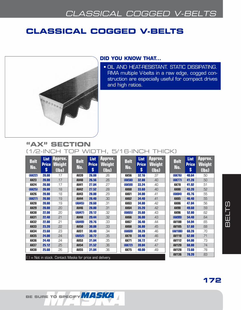
BELT
S
BE SURE TO SPECIFY
CLASSICAL COGGED V-BELTS
172
BeltNo.
ListPrice
$
Approx.Weight(lbs)
(AX22) 20.80 .17AX23 20.80 .17AX24 20.80 .17
(AX25) 20.80 .18AX26 20.80 .18
(AX27) 20.80 .19AX28 20.80 .19AX29 20.80 .20AX30 22.08 .20AX31 22.40 .21AX32 22.80 .21AX33 23.20 .22AX34 23.68 .23AX35 24.00 .24AX36 24.48 .24AX37 25.12 .25AX38 25.60 .26
“AX” SECTION(1/2-INCH TOP WIDTH, 5/16-INCH THICK)
BeltNo.
ListPrice
$
Approx.Weight(lbs)
AX39 26.08 .26AX40 26.56 .26AX41 27.04 .27AX42 27.52 .28AX43 28.00 .29AX44 28.40 .30
(AX45) 28.60 .31AX46 28.80 .31
(AX47) 29.12 .32AX48 29.44 .32
(AX49) 29.76 .33AX50 30.08 .33AX51 30.40 .34
(AX52) 30.72 .35AX53 31.04 .35AX54 31.52 .36AX55 31.84 .36
BeltNo.
ListPrice
$
Approx.Weight(lbs)
AX56 32.16 .37(AX58) 32.88 .40(AX59) 33.24 .40AX60 33.60 .40AX61 34.00 .41AX62 34.40 .41AX63 34.80 .42AX64 35.20 .42
(AX65) 35.60 .43AX66 36.00 .43AX67 36.40 .44AX68 36.80 .45
(AX69) 38.28 .46AX70 38.40 .46AX71 38.72 .47
(AX72) 39.04 .47AX75 40.00 .49
BeltNo.
ListPrice
$
Approx.Weight(lbs)
(AX76) 40.64 .50(AX77) 41.28 .50AX78 41.92 .51AX80 43.20 .52
(AX84) 45.76 .55AX85 46.40 .55AX86 47.04 .56AX90 49.60 .59AX96 52.80 .62
(AX99) 54.40 .64AX100 54.94 .65AX105 57.60 .68
(AX108) 60.28 .70AX110 62.08 .71AX112 64.00 .73AX120 68.80 .74AX128 73.60 .78AX136 78.20 .83
CLASSICAL COGGED V-BELTS
• OIL AND HEAT-RESISTANT. STATIC DISSIPATING.RMA multiple V-belts in a raw edge, cogged con-struction are especially useful for compact drivesand high ratios.
DID YOU KNOW THAT...
( ) = Not in stock. Contact Maska for price and delivery.
7-Belts1.7.qxp 2009-03-19 14:34 Page 11

BELT
S
FOR DEPENDABLE DRIVE COMPONENTS, BE SURE TO SPECIFY
CLASSICAL COGGED V-BELTS
173
BeltNo.
ListPrice
$
Approx.Weight(lbs)
BX31 32.00 .36BX32 32.00 .37
(BX33) 32.00 .39BX34 32.00 .39BX35 32.00 .40BX36 32.96 .42BX37 34.28 .43BX38 35.20 .43BX39 35.20 .45BX40 36.80 .46BX41 37.60 .47BX42 38.40 .48BX43 39.20 .49
(BX44) 40.00 .50BX45 40.80 .51BX46 41.60 .52BX47 42.24 .53BX48 42.88 .54BX49 43.52 .55BX50 44.16 .56BX51 44.80 .57BX52 45.28 .58
“BX” SECTION(21/32-INCH TOP WIDTH, 13/32-INCH THICK)
BeltNo.
ListPrice
$
Approx.Weight(lbs)
BX53 45.60 .59BX54 46.08 .60BX55 46.40 .61BX56 46.72 .62BX57 47.04 .63BX58 47.36 .64BX59 47.68 .66BX60 48.00 .67BX61 48.64 .68BX62 49.28 .69BX63 49.92 .70BX64 50.56 .71BX65 51.20 .72BX66 51.84 .73BX67 52.32 .74BX68 52.80 .75
(BX69) 53.52 .76BX70 54.24 .77BX71 54.88 .78BX73 57.60 .80
(BX74) 57.60 .81BX75 57.60 .82
BeltNo.
ListPrice
$
Approx.Weight(lbs)
(BX76) 58.40 Òw¢BX77 59.20 .85BX78 60.00 .86BX79 60.80 .87BX80 61.60 .88BX81 62.40 .89BX82 64.00 .90BX83 64.48 .91BX84 65.60 .92BX85 65.60 .93BX90 68.80 .98
(BX91) 69.90 .99(BX92) 71.00 1.00BX93 72.00 1.01BX95 73.60 1.03BX96 74.40 1.05BX97 75.20 1.06BX99 76.32 1.08BX100 76.80 1.09BX103 78.40 1.12BX105 80.00 1.14BX108 83.04 1.17
BeltNo.
ListPrice
$
Approx.Weight(lbs)
BX112 86.40 1.22(BX113) 87.04 1.22(BX115) 88.20 1.25BX116 88.80 1.26BX120 91.20 1.30BX124 94.40 1.30BX128 97.60 1.30BX133 102.40 1.34BX136 104.32 1.37BX144 110.40 1.45BX150 114.56 1.51BX158 120.00 1.59BX162 124.84 1.63BX173 131.20 1.74BX180 137.60 1.81BX195 148.80 1.96
(BX210) * 2.10(BX225) * 2.25(BX240) * 2.36(BX270) * 2.66(BX300) * 2.95
BeltNo.
ListPrice
$
Approx.Weight(lbs)
CX51 73.60 1.07CX60 86.40 1.24
(CX67) 96.20 1.37CX68 97.60 1.39
(CX72) 103.10 1.47CX75 107.20 1.53
(CX76) 108.80 1.55(CX78) 112.00 1.59(CX80) 115.20 1.62CX81 116.80 1.64
(CX82) 117.60 1.66(CX83) 118.40 1.68CX85 120.00 1.72
“CX” SECTION(7/8-INCH TOP WIDTH, 17/32-INCH THICK)
BeltNo.
ListPrice
$
Approx.Weight(lbs)
(CX88) 125.76 1.77CX90 129.60 1.81
(CX92) 132.26 1.85(CX94) 134.94 1.89(CX95) 136.26 1.91CX96 137.60 1.93
(CX98) 140.44 1.97(CX100) 143.28 2.01(CX103) 147.54 2.06CX105 150.40 2.10
(CX107) 153.12 2.14CX109 155.84 2.18
(CX110) 157.20 2.20
BeltNo.
ListPrice
$
Approx.Weight(lbs)
CX112 160.00 2.24CX115 164.16 2.29CX120 171.20 2.39
(CX123) 176.64 2.40CX128 182.40 2.42CX133 188.80 2.47CX136 192.64 2.49CX144 204.80 2.63CX150 212.16 2.75CX158 224.00 2.90CX162 228.80 2.95CX173 244.80 3.15
BeltNo.
ListPrice
$
Approx.Weight(lbs)
(CX180) 256.00 3.27(CX187) 266.64 3.39(CX190) 271.20 3.46CX195 276.80 3.55
(CX210) * 3.77(CX225) * 4.04(CX240) * 4.30(CX255) * 4.58(CX270) * 4.85(CX300) * 5.39(CX330) * 5.93(CX360) * 6.47
( ) = Not in stock. Contact Maska for price and delivery.
7-Belts1.7.qxp 2009-03-19 14:34 Page 12

BELT
S
BE SURE TO SPECIFY
NARROW V-BELTS
174
BeltNo.
ListPrice
$
Approx.Weight(lbs)
3V250 15.60 .103V265 16.00 .103V280 16.40 .103V300 16.80 .103V315 17.60 .103V335 18.00 .203V355 18.80 .203V375 19.20 .203V400 20.40 .20
“3V” SECTION(3/8-INCH TOP WIDTH, 5/16-INCH THICK)
BeltNo.
ListPrice
$
Approx.Weight(lbs)
3V425 21.20 .203V450 22.00 .203V475 22.80 .203V500 23.20 .203V530 24.00 .203V560 24.80 .203V600 26.00 .203V630 26.80 .30
(3V650) 27.40 .30
BeltNo.
ListPrice
$
Approx.Weight(lbs)
3V670 28.00 .303V710 29.60 .30
(3V730) 30.40 .303V750 31.20 .303V800 33.20 .303V830 35.60 .353V850 35.60 .403V900 38.40 .40
BeltNo.
ListPrice
$
Approx.Weight(lbs)
3V950 40.40 .403V1000 42.80 .403V1060 45.20 .403V1120 49.20 .503V1180 52.40 .503V1250 56.00 .603V1320 59.20 .603V1400 62.80 .70
BeltNo.
ListPrice
$
Approx.Weight(lbs)
5V500 49.20 .605V530 51.20 .705V560 53.60 .705V600 58.00 .70
(5V630) 60.80 .705V670 64.80 .805V710 68.80 .805V750 72.80 .805V800 77.60 .905V850 83.60 .90
“5V” SECTION(5/8-INCH TOP WIDTH, 17/32-INCH THICK)
BeltNo.
ListPrice
$
Approx.Weight(lbs)
5V900 86.80 .905V950 93.20 .90
(5V975) 95.80 1.005V1000 98.40 1.10
(5V1020) 100.40 1.105V1060 104.40 1.105V1120 110.40 1.205V1180 116.40 1.305V1250 123.60 1.305V1320 130.40 1.40
BeltNo.
ListPrice
$
Approx.Weight(lbs)
5V1400 137.60 1.505V1500 148.00 1.605V1600 158.00 1.70
(5V1630) 161.20 1.805V1700 168.00 1.80
(5V1710) 169.04 1.845V1800 178.40 2.205V1900 188.80 2.205V2000 199.20 2.205V2120 211.60 2.40
BeltNo.
ListPrice
$
Approx.Weight(lbs)
(5V2150) 214.70 2.485V2240 224.00 2.705V2360 235.20 2.805V2500 249.20 3.00
(5V2650) 264.80 3.105V2800 279.20 3.305V3000 298.80 3.50
(5V3150) 313.60 3.80(5V3350) 333.60 3.90(5V3550) 353.60 4.00
NARROW V-BELTS
• OIL AND HEAT-RESISTANT. STATIC DISSIPATING.A more narrow, deeper wedge shape withmore efficient load carrying characteristics andhigher power capability that results in smaller,more compact drives.
• These belts are conform to RMA EngineeringStandard IP-22. Stock Maska narrow V-belts arelisted below. In-between lengths and lengths over600 inches are available on special order.
DID YOU KNOW THAT...
( ) = Not in stock. Contact Maska for price and delivery.
7-Belts1.7.qxp 2009-03-19 14:34 Page 13

BELT
S
FOR DEPENDABLE DRIVE COMPONENTS, BE SURE TO SPECIFY
NARROW V-BELTS
175
BeltNo.
ListPrice
$
Approx.Weight(lbs)
(8V1000) 188.00 3.50(8V1060) 199.20 3.70(8V1120) 210.80 3.908V1180 222.40 4.208V1250 235.60 4.408V1320 248.80 4.708V1400 264.00 4.908V1500 283.20 5.208V1600 302.00 5.60
(8V1650) 313.00 5.75
“8V” SECTION(1-INCH TOP WIDTH, 7/8-INCH THICK)
BeltNo.
ListPrice
$
Approx.Weight(lbs)
8V1700 324.00 5.908V1800 340.16 6.308V1900 361.20 6.708V2000 380.80 7.008V2120 404.40 7.508V2240 426.40 7.90
(8V2300) 437.40 8.108V2360 448.40 8.308V2500 474.80 8.80
(8V2550) 484.40 8.97
BeltNo.
ListPrice
$
Approx.Weight(lbs)
8V2650 503.60 9.308V2800 533.20 9.808V3000 571.20 10.508V3150 600.40 11.10
(8V3300) 629.50 11.638V3350 639.20 11.808V3550 677.20 12.50
(8V3600) 686.74 12.90(8V3750) 716.00 13.30(8V4000) 765.60 14.00
BeltNo.
ListPrice
$
Approx.Weight(lbs)
(8V4250) 815.20 14.90(8V4500) 864.80 15.80(8V4750) 914.40 16.40(8V5000) 964.00 17.20(8V5600) 1083.20 19.00
( ) = Not in stock. Contact Maska for price and delivery.
LINK V-BELTSPart No. List Price* $
3L-LINK 726.00A-LINK 740.00B-LINK 862.00C-LINK 1302.00
Solve a V-Belt Drive breakdown quickly
Accu-Link3L, A, B, C, BB, CC
* List Price per standard length of 25 feet
• The ideal temporary replacement, orpermanent substitute, for convention-al rubber V-Belts (not cogged)
• Designed to fit any drive applicationand diverse operating environments
• Quick, easy assembly to keep equipment up and running at thesame HP ratings
DID YOU KNOW THAT...
LINK V-BELTS
7-Belts1.7.qxp 2009-03-19 14:34 Page 14

BELT
S
BE SURE TO SPECIFY
NARROW COGGED V-BELTS
176
BeltNo.
ListPrice
$
Approx.Weight(lbs)
3VX250 15.60 .103VX265 16.00 .103VX280 16.40 .10
(3VX290) 16.60 .103VX300 16.80 .103VX315 17.60 .103VX335 18.00 .203VX355 18.80 .203VX375 19.20 .20
“3VX” SECTION(3/8-INCH TOP WIDTH, 5/16-INCH THICK)
BeltNo.
ListPrice
$
Approx.Weight(lbs)
3VX390 20.00 .203VX400 20.40 .203VX425 21.20 .203VX450 22.00 .203VX475 22.80 .203VX500 23.20 .203VX520 23.70 .203VX530 24.00 .203VX560 24.80 .20
BeltNo.
ListPrice
$
Approx.Weight(lbs)
3VX600 26.00 .303VX630 26.80 .30
(3VX650) 27.40 .303VX670 28.00 .303VX710 29.60 .303VX750 31.20 .303VX800 33.20 .403VX850 35.60 .403VX900 38.40 .40
BeltNo.
ListPrice
$
Approx.Weight(lbs)
3VX950 40.40 .403VX1000 42.80 .403VX1060 45.20 .503VX1120 49.20 .503VX1180 52.40 .603VX1250 56.00 .603VX1320 59.20 .703VX1400 62.80 .70
BeltNo.
ListPrice
$
Approx.Weight(lbs)
(5VX470) 49.20 .605VX500 49.20 .605VX530 51.20 .705VX560 53.60 .70
(5VX570) 53.10 .705VX600 58.00 .705VX630 60.80 .705VX650 62.80 .805VX660 63.80 .805VX670 64.80 .80
“5VX” SECTION (5/8-INCH TOP WIDTH, 17/32-INCH THICK)
BeltNo.
ListPrice
$
Approx.Weight(lbs)
5VX680 65.80 .805VX690 66.80 .805VX710 68.80 .805VX730 70.80 .805VX750 72.80 .80
(5VX780) 75.70 .905VX800 77.60 .905VX850 83.60 .905VX900 86.80 1.005VX950 93.20 1.10
BeltNo.
ListPrice
$
Approx.Weight(lbs)
(5VX960) 94.20 1.105VX1000 98.40 1.20
(5VX1030) 101.40 1.205VX1060 104.40 1.20
(5VX1080) 110.40 1.205VX1120 110.40 1.30
(5VX1150) 113.40 1.405VX1180 116.40 1.405VX1230 121.50 1.50
BeltNo.
ListPrice
$
Approx.Weight(lbs)
5VX1250 123.60 1.505VX1320 130.40 1.605VX1400 137.60 1.705VX1500 148.00 1.805VX1600 158.00 1.905VX1700 168.00 2.005VX1800 178.40 2.105VX1900 188.80 2.305VX2000 199.20 2.40
NARROW COGGED V-BELTS
• A raw edge, cogged construction further increases the effective power transmission ofnarrow V-belts
DID YOU KNOW THAT...
( ) = Not in stock. Contact Maska for price and delivery.
7-Belts1.7.qxp 2009-03-19 14:34 Page 15
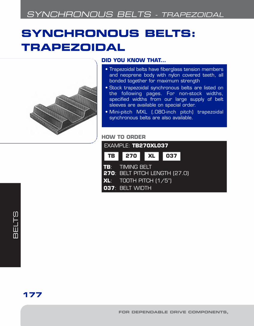
BELT
S
FOR DEPENDABLE DRIVE COMPONENTS, BE SURE TO SPECIFY
SYNCHRONOUS BELTS - TRAPEZOIDAL
177
SYNCHRONOUS BELTS:TRAPEZOIDAL
EXAMPLE: TB270XL037
TB 270
TB: TIMING BELT270: BELT PITCH LENGTH (27.0)XL: TOOTH PITCH (1/5’’)037: BELT WIDTH
HOW TO ORDER
XL 037
• Trapezoidal belts have fiberglass tension membersand neoprene body with nylon covered teeth, allbonded together for maximum strength
• Stock trapezoidal synchronous belts are listed onthe following pages. For non-stock widths, specified widths from our large supply of beltsleeves are available on special order.
• Mini-pitch MXL (.080-inch pitch) trapezoidal synchronous belts are also available.
DID YOU KNOW THAT...
7-Belts1.7.qxp 2009-03-19 14:34 Page 16

BELT
S
BE SURE TO SPECIFY
SYNCHRONOUS BELTS - TRAPEZOIDAL
178
BeltLength& PitchCode
No.of
Teeth
Width 037 (3/8”)
ListPrice
$
Approx.Weight(lbs.)
60XL 30 7.68 0.009
70XL 35 8.00 0.011
80XL 40 8.24 0.012
90XL 45 8.48 0.014
100XL 50 8.72 0.015
110XL 55 9.04 0.017
120XL 60 9.20 0.019
130XL 65 9.52 0.02
140XL 70 9.76 0.022
142XL 71 9.80 0.023
150XL 75 10.00 0.023
160XL 80 10.32 0.025
170XL 85 10.48 0.026
178XL 89 10.74 0.028
180XL 90 10.80 0.028
190XL 95 11.04 0.029
194XL 97 11.28 0.03
200XL 100 11.28 0.031
210XL 105 11.52 0.032
220XL 110 11.84 0.034
230XL 115 12.00 0.035
240XL 120 12.52 0.037
250XL 125 12.56 0.039
260XL 130 12.80 0.04
270XL 135 13.16 0.041
344XL 172 14.96 0.051
XL - EXTRA LIGHT 1/5" PITCH L- LIGHT 3/8" PITCH
BeltLength& PitchCode
No. ofTeeth
Width050 (1/2”) 075 (3/4”) 100 (1”)
ListPrice
$
Approx.Weight(lbs.)
ListPrice
$
Approx.Weight(lbs.)
ListPrice
$
Approx.Weight(lbs.)
124L 33 15.36 .02 21.84 .05 28.00 .07135L 36 POR .02 POR .05 POR .07150L 40 16.96 .03 24.24 .05 31.20 .07165L 44 17.44 .03 25.04 .06 32.28 .08173L 46 18.00 .03 25.84 .06 33.40 .08187L 50 18.48 .04 26.64 .07 34.48 .09202L 54 19.60 .04 28.24 .08 36.68 .09210L 56 20.08 .04 29.04 .08 37.68 .09225L 60 20.64 .05 29.84 .08 38.76 .10236L 63 21.42 .06 31.04 .08 40.42 .10240L 64 21.68 .06 31.44 .08 40.96 .12244L 65 21.80 .06 31.64 .08 41.24 .12255L 68 22.16 .06 32.24 .09 42.04 .12270L 72 23.20 .06 33.84 .10 44.16 .13285L 76 23.76 .07 34.72 .10 45.24 .14300L 80 24.80 .07 36.24 .11 47.44 .14320L 85 25.80 .07 37.80 .12 49.40 .15322L 86 25.84 .07 37.92 .12 49.60 .15345L 92 26.88 .08 39.52 .13 51.72 .16367L 98 27.84 .08 41.12 .13 53.88 .17390L 104 29.44 .09 43.52 .14 57.08 .18405L 108 POR .09 POR .14 POR .19412L 110 POR .10 POR .15 POR .20420L 112 30.96 .10 45.92 .15 60.36 .20424L 113 31.16 .11 46.24 .16 60.76 .22450L 120 32.56 .11 48.40 .16 63.56 .22454L 121 32.76 .11 48.70 .16 63.98 .22480L 128 34.16 .12 50.80 .17 66.84 .23510L 136 35.20 .12 52.40 .18 69.04 .24525L 140 POR .12 POR .19 POR .25540L 144 37.28 .13 55.60 .20 73.32 .26600L 160 40.40 .13 60.48 .21 79.80 .28660L 178 43.52 .14 66.52 .23 87.78 .29728L 194 POR .15 POR .25 POR .30817L 218 53.60 .18 80.40 .29 107.20 .36915L 244 POR .20 POR .32 POR .40
P.O.R. = Price on request
7-Belts1.7.qxp 2009-03-19 14:34 Page 17
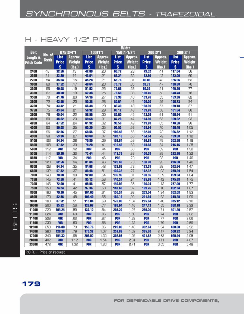
BELT
S
FOR DEPENDABLE DRIVE COMPONENTS, BE SURE TO SPECIFY
SYNCHRONOUS BELTS - TRAPEZOIDAL
179
H - HEAVY 1/2" PITCH
BeltLength &
Pitch Code
No. ofTeeth
Width075(3/4”) 100(1”) 150(1-1/2”) 200(2”) 300(3”)
ListPrice
$
Approx.Weight(lbs.)
ListPrice
$
Approx.Weight(lbs.)
ListPrice
$
Approx.Weight(lbs.)
ListPrice
$
Approx.Weight(lbs.)
ListPrice
$
Approx.Weight(lbs.)
240H 48 32.56 .13 42.00 .20 60.72 .28 79.52 .41 117.04 .56255H 51 33.80 .14 43.64 .21 63.24 .30 82.80 .42 122.00 .60270H 54 35.04 .15 45.28 .21 65.76 .31 86.08 .43 126.96 .63300H 60 37.52 .17 48.64 .23 70.72 .35 92.72 .47 136.88 .70330H 66 40.08 .19 51.92 .25 75.68 .38 99.36 .51 146.80 .77335H 67 40.50 .19 52.48 .25 76.50 .38 100.46 .52 148.44 .78350H 70 41.76 .20 54.16 .27 78.96 .40 103.76 .55 153.36 .82360H 72 42.56 .20 55.28 .28 80.64 .42 106.00 .56 156.72 .84370H 74 43.42 .21 56.38 .29 82.30 .43 108.20 .57 159.18 .87375H 75 43.84 .21 56.92 .29 83.12 .43 109.28 .58 161.64 .88390H 78 45.04 .22 58.56 .30 85.60 .45 112.56 .61 166.64 .91400H 80 45.92 .23 59.68 .31 87.28 .47 114.80 .63 169.92 .93420H 84 47.52 .24 61.92 .32 90.56 .49 119.20 .65 176.56 .98450H 90 50.08 .25 65.20 .35 95.52 .52 125.84 .70 186.40 1.05480H 96 52.56 .27 68.56 .37 100.48 .56 132.40 .72 196.32 1.12490H 98 53.36 .27 69.68 .37 102.16 .56 134.64 .72 199.68 1.12510H 102 54.24 .28 70.80 .39 103.84 .59 136.88 .79 202.96 1.18540H 108 57.52 .30 75.20 .41 110.48 .63 145.68 .84 216.16 1.25560H 112 POR .32 POR .44 POR .66 POR .89 POR 1.32570H 114 59.20 .32 77.44 .44 113.76 .66 150.08 .89 222.80 1.32585H 117 POR .34 POR .46 POR .70 POR .93 POR 1.40600H 120 62.56 .34 81.84 .46 120.40 .70 158.88 .93 236.00 1.40630H 126 64.24 .35 84.08 .48 123.68 .73 163.28 .98 242.64 1.47660H 132 67.52 .37 88.48 .51 130.32 .77 172.12 1.02 255.84 1.54700H 140 70.88 .39 92.88 .54 136.96 .81 180.96 1.09 269.04 1.64725H 145 72.56 .41 95.12 .56 140.24 .84 185.36 1.12 275.68 1.75730H 146 72.90 .41 95.56 .57 140.92 .85 186.24 1.13 277.00 1.77750H 150 74.24 .42 97.36 .58 143.60 .87 189.76 1.16 282.24 1.87800H 160 79.20 .45 104.00 .61 150.24 .93 203.04 1.24 302.08 1.93850H 170 82.56 .48 108.40 .65 160.16 .99 211.84 1.32 315.28 1.99900H 180 87.52 .51 115.04 .69 170.08 1.04 225.04 1.40 335.12 2.101000H 200 95.92 .56 126.08 .77 186.64 1.16 247.12 1.55 368.16 2.321100H 220 104.24 .59 137.12 .84 203.20 1.27 269.20 1.71 401.20 2.571120H 224 POR .60 POR .86 POR 1.30 POR 1.74 POR 2.621140H 228 POR .62 POR .87 POR 1.32 POR 1.77 POR 2.661150H 230 POR .63 POR .88 POR 1.33 POR 1.79 POR 2.691250H 250 116.80 .70 153.76 .96 228.08 1.46 302.24 1.94 450.80 2.921400H 280 129.28 .79 170.32 1.07 252.88 1.62 335.36 2.17 500.32 3.241700H 340 154.32 .95 203.52 1.30 302.56 1.95 401.52 2.63 599.44 3.952010H 402 POR 1.12 POR 1.54 POR 2.31 POR 3.11 POR 4.672360H 472 POR 1.32 POR 1.80 POR 2.71 POR 3.65 POR 5.48
P.O.R. = Price on request
7-Belts1.7.qxp 2009-03-19 14:34 Page 18

BELT
S
BE SURE TO SPECIFY
SYNCHRONOUS BELTS - CURVILINEAR
180
EXAMPLE: HTB13048M020
HTB 1304
HTB: HIGH TORQUE BELT1304: BELT PITCH LENGTH (1304mm)8M: TOOTH PITCH (8mm)020: BELT WIDTH (20mm)
HOW TO ORDER
8M 020
A. A high-modulus fiberglasscord is wound across theentire width of the belt pitchline insuring minimal stretchand resistance to repeatedflexing.
B. The body is a synthetic neoprene compounded toresist flex fatigue, heat, ozone, mineral lubricatingoils and aging.
C. A tough nylon fabric is bonded to the tooth surface for wear resistance.
• Our stock 8mm and 14mm curvilinear synchronousbelts are listed on the following pages. Non-standardlengths in these pitches are also available, as arebelts with 3mm and 5mm pitch.
• Higher torque transmission at low speeds• High power transmission over a wide speed range• Improved meshing to reduce tooth jump• Higher resistance to tooth shear• Less tooth wear due to friction
DID YOU KNOW THAT...
The standard trapezoidal tooth timing belt designperforms poorly in high torque applications andhigh power drives at lower speeds. To overcomethis disadvantage the curvilinear belt was devel-oped using a more efficient tooth profile.
SYNCHRONOUS BELTS:CURVILINEAR
7-Belts1.7.qxp 2009-03-19 14:34 Page 19
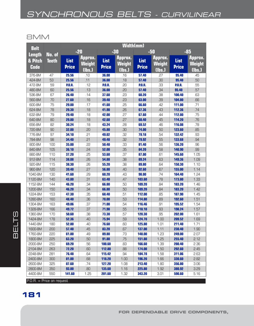
BELT
S
FOR DEPENDABLE DRIVE COMPONENTS, BE SURE TO SPECIFY
SYNCHRONOUS BELTS - CURVILINEAR
181
8MM
BeltLength& PitchCode
No. ofTeeth
Width(mm)-20 -30 -50 -85
ListPrice
Approx.Weight(lbs.)
ListPrice
Approx.Weight(lbs.)
ListPrice
Approx.Weight(lbs.)
ListPrice
Approx.Weight(lbs.)
376-8M 47 25.56 .10 36.00 .16 57.40 .27 95.40 .45424-8M 53 25.56 .11 36.00 .18 57.40 .30 95.40 .50472-8M 59 P.O.R. .12 P.O.R. .20 P.O.R. .33 P.O.R. .55480-8M 60 25.56 .13 36.00 .20 57.40 .34 95.40 .57536-8M 67 26.40 .14 37.60 .23 60.20 .38 100.40 .63560-8M 70 27.60 .16 39.40 .23 63.00 .39 104.80 .66600-8M 75 29.00 .17 41.60 .25 66.60 .42 111.00 .71624-8M 78 29.30 .18 41.90 .26 67.36 .43 112.36 .74632-8M 79 29.40 .18 42.00 .27 67.60 .44 112.80 .75640-8M 80 29.80 .18 42.60 .27 68.40 .45 114.20 .76656-8M 82 30.24 .18 43.24 .28 69.52 .46 116.08 .78720-8M 90 32.00 .20 45.80 .30 74.00 .50 123.60 .85776-8M 97 34.10 .21 49.02 .32 79.18 .54 132.42 .93784-8M 98 34.40 .21 49.48 .32 79.92 .55 133.68 .94800-8M 100 35.00 .22 50.40 .33 81.40 .56 136.20 .96840-8M 105 36.10 .24 52.00 .35 84.20 .58 140.90 .99880-8M 110 37.20 .25 53.60 .37 87.00 .61 145.60 1.05912-8M 114 38.08 .26 54.88 .38 89.24 .63 149.36 1.09920-8M 115 38.30 .26 55.20 .38 89.80 .64 150.30 1.10960-8M 120 39.40 .27 56.80 .40 92.60 .67 155.00 1.141040-8M 130 41.60 .29 60.20 .43 98.00 .74 164.40 1.241120-8M 140 43.80 .31 63.40 .47 103.60 .78 173.80 1.331152-8M 144 46.20 .34 66.80 .50 109.20 .84 183.20 1.461200-8M 150 46.20 .34 66.80 .50 109.20 .84 183.20 1.421224-8M 153 47.30 .35 68.40 .51 112.00 .85 187.90 1.451280-8M 160 48.40 .36 70.00 .53 114.80 .89 192.60 1.511304-8M 163 49.06 .37 71.00 .54 116.46 .91 195.52 1.541328-8M 166 49.72 .37 71.98 .55 118.10 .93 198.24 1.571360-8M 170 50.60 .38 73.30 .57 120.30 .95 202.00 1.611424-8M 178 52.36 .40 75.94 .59 124.70 1.00 209.52 1.691440-8M 180 52.80 .40 76.60 .60 125.80 1.01 211.40 1.711600-8M 200 57.40 .45 83.20 .67 137.00 1.11 230.40 1.901760-8M 220 61.80 .49 89.80 .73 148.00 1.23 249.00 2.071800-8M 225 63.20 .50 91.80 .75 151.80 1.25 255.40 2.122000-8M 250 69.20 .56 100.60 .83 166.60 1.39 280.40 2.362104-8M 263 72.20 .60 112.80 .88 174.00 1.50 292.60 2.452248-8M 281 76.48 .64 115.42 .94 184.78 1.58 311.06 2.632400-8M 300 81.00 .68 118.20 1.00 196.20 1.66 330.60 2.822600-8M 325 87.60 .74 127.20 1.08 213.40 1.80 356.80 3.062800-8M 350 93.00 .80 135.60 1.16 225.80 1.92 380.92 3.294400-8M 550 141.60 1.25 201.60 1.32 343.20 3.01 590.60 5.16
P.O.R. = Price on request
7-Belts1.7.qxp 2009-03-19 14:34 Page 20
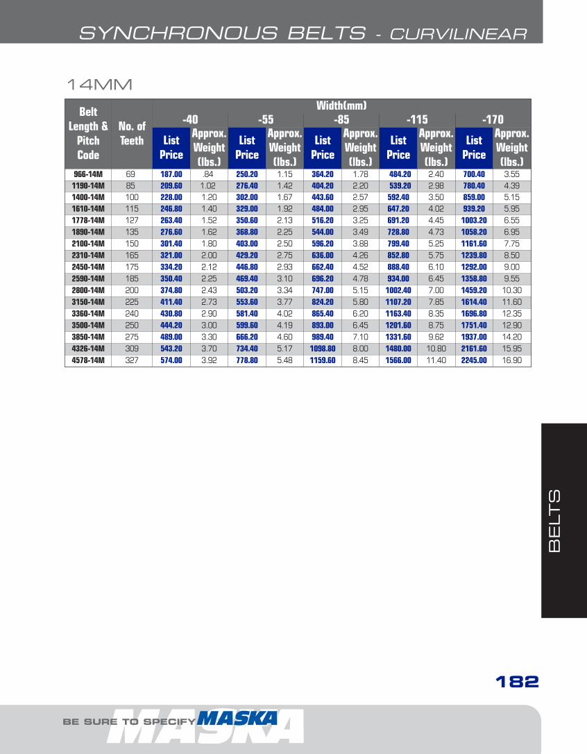
BELT
S
BE SURE TO SPECIFY
SYNCHRONOUS BELTS - CURVILINEAR
182
14MM
BeltLength &
PitchCode
No. ofTeeth
Width(mm)-40 -55 -85 -115 -170
ListPrice
Approx.Weight(lbs.)
ListPrice
Approx.Weight(lbs.)
ListPrice
Approx.Weight(lbs.)
ListPrice
Approx.Weight(lbs.)
ListPrice
Approx.Weight(lbs.)
966-14M 69 187.00 .84 250.20 1.15 364.20 1.78 484.20 2.40 700.40 3.551190-14M 85 209.60 1.02 276.40 1.42 404.20 2.20 539.20 2.98 780.40 4.391400-14M 100 228.00 1.20 302.00 1.67 443.60 2.57 592.40 3.50 859.00 5.151610-14M 115 246.80 1.40 329.00 1.92 484.00 2.95 647.20 4.02 939.20 5.951778-14M 127 263.40 1.52 350.60 2.13 516.20 3.25 691.20 4.45 1003.20 6.551890-14M 135 276.60 1.62 368.80 2.25 544.00 3.49 728.80 4.73 1058.20 6.952100-14M 150 301.40 1.80 403.00 2.50 596.20 3.88 799.40 5.25 1161.60 7.752310-14M 165 321.00 2.00 429.20 2.75 636.00 4.26 852.80 5.75 1239.80 8.502450-14M 175 334.20 2.12 446.80 2.93 662.40 4.52 888.40 6.10 1292.00 9.002590-14M 185 350.40 2.25 469.40 3.10 696.20 4.78 934.00 6.45 1358.80 9.552800-14M 200 374.80 2.43 503.20 3.34 747.00 5.15 1002.40 7.00 1459.20 10.303150-14M 225 411.40 2.73 553.60 3.77 824.20 5.80 1107.20 7.85 1614.40 11.603360-14M 240 430.80 2.90 581.40 4.02 865.40 6.20 1163.40 8.35 1696.80 12.353500-14M 250 444.20 3.00 599.60 4.19 893.00 6.45 1201.60 8.75 1751.40 12.903850-14M 275 489.00 3.30 666.20 4.60 989.40 7.10 1331.60 9.62 1937.00 14.204326-14M 309 543.20 3.70 734.40 5.17 1098.80 8.00 1480.00 10.80 2161.60 15.954578-14M 327 574.00 3.92 778.80 5.48 1159.60 8.45 1566.00 11.40 2245.00 16.90
7-Belts1.7.qxp 2009-03-19 14:34 Page 21
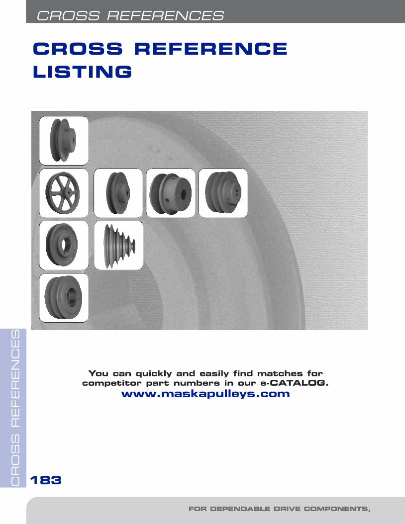
CR
OS
S R
EFER
EN
CES
FOR DEPENDABLE DRIVE COMPONENTS, BE SURE TO SPECIFY FOR DEPENDABLE DRIVE COMPONENTS, BE SUR
183
CROSS REFERENCES
CROSS REFERENCELISTING
You can quickly and easily find matches forcompetitor part numbers in our e-CATALOG.
www.maskapulleys.com
8-Cross Ref.4.qxp 2009-03-19 14:36 Page 2

CR
OS
S R
EFER
EN
CES
BE SURE TO SPECIFY BE SURE TO SPECIFY
184
CROSS REFERENCES
VL 25 MVL 25VL 30 MVL 30VL 34 MVL 34VL 40 MVL 40VL 44 MVL 44
AL 54 MFAL 54AL 64 MFAL 64AL 74 MFAL 74AL 84 MFAL 84AL 94 MFAL 94AL 104 MFAL 104AL 114 MFAL 114AL 124 MFAL 124AM 144 MFAM 144
VARIABLE LIGHT DUTYFRACTIONNAL FIXEDBORE A GROOVE
H.V.A.C. VARIABLE F.H.P.
VARIABLE PITCH INTEGRAL VP-2VP/8000 SERIES
1VP 34 83251VP 40 83501VP 44 84001VP 50 84501VP 56 8550
1VP 60/1VP62/1VP65 86001VP 68/1VP71 8670
1VP 75 8740
2VP 36 D83502VP 42 D84002VP 50 D84502VP 56 D8550
2VP 60/1VP62/1VP65 D86002VP 68/1VP71 D8670
2VP 75 D8740
V-BELT SHEAVESINGLE GROOVE
V-BELT SHEAVEDOUBLE GROOVE
MVS ADJUSTABLE SPEED
JVS 130 MVS 130JVS 150 MVS 150JVS 170 MVS 170JVS 190 MVS 190JVS 210 MVS 210JVS 230 MVS 230
Cross Ref. Cross Ref.
Cross Ref.
8-Cross Ref.4.qxp 2009-03-19 14:36 Page 3
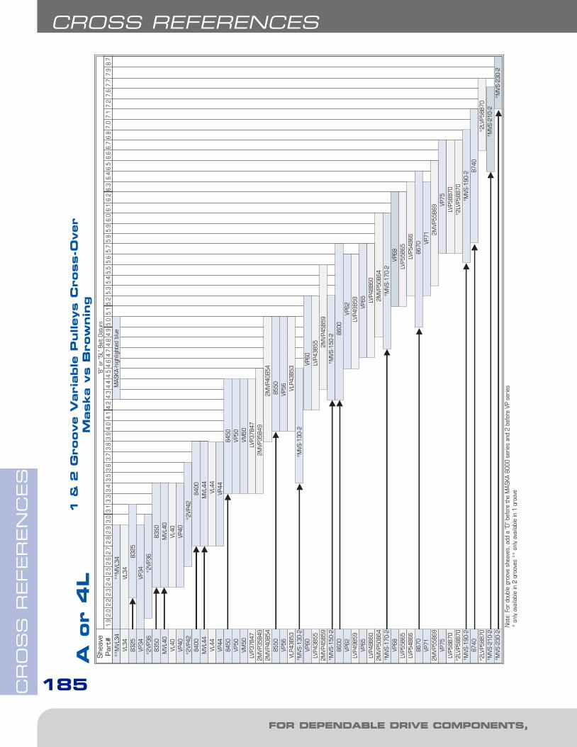
CR
OS
S R
EFER
EN
CES
FOR DEPENDABLE DRIVE COMPONENTS, BE SURE TO SPECIFY FOR DEPENDABLE DRIVE COMPONENTS, BE SUR
CROSS REFERENCES
185
8-Cross Ref.4.qxp 2009-03-19 14:36 Page 4

BE SURE TO SPECIFY BE SURE TO SPECIFY
CR
OS
S R
EFER
EN
CES
CROSS REFERENCES
186
8-Cross Ref.4.qxp 2009-03-19 14:36 Page 5
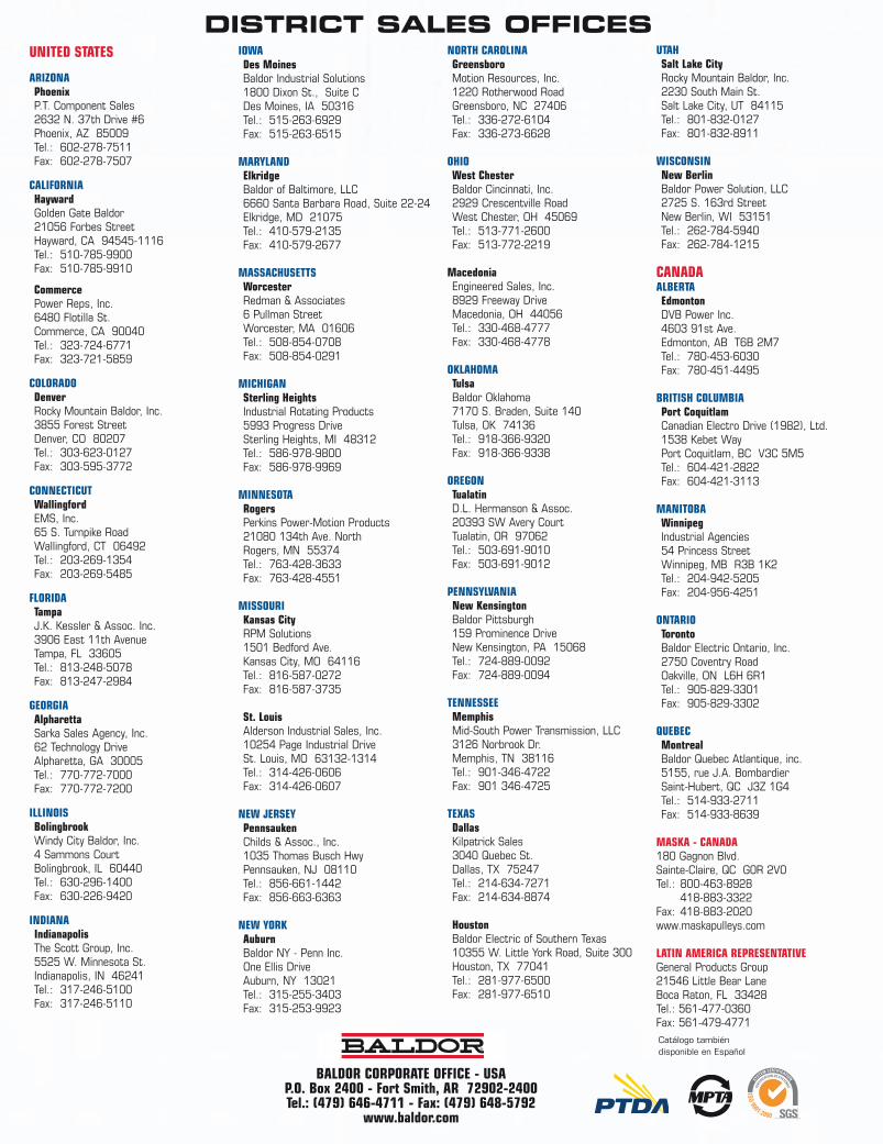
UNITED STATES
ARIZONAPhoenixP.T. Component Sales2632 N. 37th Drive #6 Phoenix, AZ 85009Tel.: 602-278-7511Fax: 602-278-7507
CALIFORNIAHaywardGolden Gate Baldor21056 Forbes Street Hayward, CA 94545-1116Tel.: 510-785-9900Fax: 510-785-9910
CommercePower Reps, Inc.6480 Flotilla St. Commerce, CA 90040Tel.: 323-724-6771Fax: 323-721-5859
COLORADODenverRocky Mountain Baldor, Inc.3855 Forest Street Denver, CO 80207Tel.: 303-623-0127Fax: 303-595-3772
CONNECTICUTWallingfordEMS, Inc.65 S. Turnpike Road Wallingford, CT 06492Tel.: 203-269-1354Fax: 203-269-5485
FLORIDATampaJ.K. Kessler & Assoc. Inc.3906 East 11th Avenue Tampa, FL 33605Tel.: 813-248-5078Fax: 813-247-2984
GEORGIAAlpharettaSarka Sales Agency, Inc.62 Technology Drive Alpharetta, GA 30005Tel.: 770-772-7000Fax: 770-772-7200
ILLINOISBolingbrookWindy City Baldor, Inc.4 Sammons Court Bolingbrook, IL 60440Tel.: 630-296-1400Fax: 630-226-9420
INDIANAIndianapolisThe Scott Group, Inc.5525 W. Minnesota St. Indianapolis, IN 46241Tel.: 317-246-5100Fax: 317-246-5110
IOWADes MoinesBaldor Industrial Solutions1800 Dixon St., Suite CDes Moines, IA 50316Tel.: 515-263-6929Fax: 515-263-6515
MARYLANDElkridgeBaldor of Baltimore, LLC6660 Santa Barbara Road, Suite 22-24Elkridge, MD 21075Tel.: 410-579-2135Fax: 410-579-2677
MASSACHUSETTSWorcesterRedman & Associates6 Pullman Street Worcester, MA 01606Tel.: 508-854-0708Fax: 508-854-0291
MICHIGANSterling HeightsIndustrial Rotating Products5993 Progress Drive Sterling Heights, MI 48312Tel.: 586-978-9800Fax: 586-978-9969
MINNESOTARogersPerkins Power-Motion Products21080 134th Ave. North Rogers, MN 55374Tel.: 763-428-3633Fax: 763-428-4551
MISSOURIKansas CityRPM Solutions1501 Bedford Ave. Kansas City, MO 64116Tel.: 816-587-0272Fax: 816-587-3735
St. LouisAlderson Industrial Sales, Inc.10254 Page Industrial Drive St. Louis, MO 63132-1314Tel.: 314-426-0606Fax: 314-426-0607
NEW JERSEYPennsaukenChilds & Assoc., Inc.1035 Thomas Busch Hwy Pennsauken, NJ 08110Tel.: 856-661-1442Fax: 856-663-6363
NEW YORKAuburnBaldor NY - Penn Inc.One Ellis Drive Auburn, NY 13021Tel.: 315-255-3403Fax: 315-253-9923
NORTH CAROLINAGreensboroMotion Resources, Inc.1220 Rotherwood Road Greensboro, NC 27406Tel.: 336-272-6104Fax: 336-273-6628
OHIOWest ChesterBaldor Cincinnati, Inc.2929 Crescentville Road West Chester, OH 45069Tel.: 513-771-2600Fax: 513-772-2219
MacedoniaEngineered Sales, Inc.8929 Freeway Drive Macedonia, OH 44056Tel.: 330-468-4777Fax: 330-468-4778
OKLAHOMATulsaBaldor Oklahoma7170 S. Braden, Suite 140Tulsa, OK 74136Tel.: 918-366-9320Fax: 918-366-9338
OREGONTualatinD.L. Hermanson & Assoc.20393 SW Avery Court Tualatin, OR 97062Tel.: 503-691-9010Fax: 503-691-9012
PENNSYLVANIANew KensingtonBaldor Pittsburgh159 Prominence Drive New Kensington, PA 15068Tel.: 724-889-0092Fax: 724-889-0094
TENNESSEEMemphisMid-South Power Transmission, LLC3126 Norbrook Dr. Memphis, TN 38116Tel.: 901-346-4722Fax: 901 346-4725
TEXASDallasKilpatrick Sales3040 Quebec St. Dallas, TX 75247Tel.: 214-634-7271Fax: 214-634-8874
HoustonBaldor Electric of Southern Texas10355 W. Little York Road, Suite 300Houston, TX 77041Tel.: 281-977-6500Fax: 281-977-6510
UTAHSalt Lake CityRocky Mountain Baldor, Inc.2230 South Main St. Salt Lake City, UT 84115Tel.: 801-832-0127Fax: 801-832-8911
WISCONSINNew BerlinBaldor Power Solution, LLC2725 S. 163rd Street New Berlin, WI 53151Tel.: 262-784-5940Fax: 262-784-1215
CANADAALBERTAEdmontonDVB Power Inc.4603 91st Ave. Edmonton, AB T6B 2M7Tel.: 780-453-6030Fax: 780-451-4495
BRITISH COLUMBIAPort CoquitlamCanadian Electro Drive (1982), Ltd.1538 Kebet Way Port Coquitlam, BC V3C 5M5Tel.: 604-421-2822Fax: 604-421-3113
MANITOBAWinnipegIndustrial Agencies54 Princess Street Winnipeg, MB R3B 1K2Tel.: 204-942-5205Fax: 204-956-4251
ONTARIOTorontoBaldor Electric Ontario, Inc.2750 Coventry Road Oakville, ON L6H 6R1Tel.: 905-829-3301Fax: 905-829-3302
QUEBECMontrealBaldor Quebec Atlantique, inc.5155, rue J.A. Bombardier Saint-Hubert, QC J3Z 1G4Tel.: 514-933-2711Fax: 514-933-8639
MASKA - CANADA180 Gagnon Blvd.Sainte-Claire, QC G0R 2V0Tel.: 800-463-8928
418-883-3322Fax: 418-883-2020www.maskapulleys.com
LATIN AMERICA REPRESENTATIVEGeneral Products Group21546 Little Bear LaneBoca Raton, FL 33428Tel.: 561-477-0360Fax: 561-479-4771
DISTRICT SALES OFFICES
Catálogo tambiéndisponible en Español
BALDOR CORPORATE OFFICE - USAP.O. Box 2400 - Fort Smith, AR 72902-2400Tel.: (479) 646-4711 - Fax: (479) 648-5792
www.baldor.com
Couverts #26.qxp 2009-04-01 14:46 Page 1