english avic-90dvd installation manual · installation manual ... • make sure that wires will not...
TRANSCRIPT

ENG/MASTER COVER 98 INST
MANUEL D’INSTALLATION
AVIC-90DVD
INST
ALLA
TION
MAN
UAL
EN
GLIS
HFR
AN
ÇA
ISD
EU
TS
CH
ITA
LIAN
ON
ED
ER
LAN
DS
This product conforms to CEMA cord colors.Le code de couleur des câbles utilisé pour ce produit estconforme à CEMA.
CRD3650A_inst_cover 4/15/02 2:22 PM Page 3

1
IMPORTANT INFORMATION
ABOUT YOUR NEW DVD NAVIGATION UNIT AND THIS MANUAL
• The Pioneer DVD Navigation Unit is intended solely as an aid to you in the oper-ation of your car. It is not a substitute for your attentiveness, judgment and carewhile driving.
• Do not use your navigation system to route you to emergency services such ashospitals or police stations. Not all emergency service facilities are contained inthe map data.
• Do not operate the DVD Navigation Unit if doing so will divert your attentionfrom the safe operation of your car. Always observe safe driving rules and followall existing traffic regulations.
• Certain state laws may restrict the placement and use of navigation systems inyour car. Please comply with all applicable laws and regulations in the installa-tion and operation of your navigation system.
• This manual explains how to install this DVD Navigation Unit in your car.Operation of this DVD Navigation Unit is explained in the separate “OperationManual” that also came with this unit.
ENG/MASTER 96 2
CRD3650A_inst_001_030_Eng 4/15/02 2:17 PM Page 2

3
IMPORTANT SAFEGUARDS .................... 3PLEASE READ ALL OF THESE
INSTRUCTIONS REGARDING YOUR DVD NAVIGATION UNIT AND RETAIN THEM FOR FUTURE REFERENCE .................... 3
Connecting the System ............................ 5CAUTION ........................................................ 5
- Before installing the unit- To prevent damage- Parts supplied
Connecting the system ...................................... 7- Connecting to the display with 26-pin
RGB input (AVH-P6400CD, AVH-P6400, etc.)
- Connecting to the display with 20-pin RGB input
Connecting the System (In case of a display sold in the market) .... 9
Connecting the power cord (1) ........................ 11Connecting the power cord (2) ........................ 13
Installation ................................................ 14CAUTION ...................................................... 14To guard against electromagnetic
interference ................................................15Before installing and fixing ............................ 15Before using the adhesive tape ........................ 15Installing the main unit .................................... 16
- Installation notes- Parts supplied- CAUTION- If you install with the left and right sides
of the DVD Navigation Unit parallel to your car’s forward / backward direction
- When installing the main unit inside thetrunk, on the floor under a seat, etc., usingtapping screws
- CAUTION- DIN Rear-mount: Installation using the screw
holes on the side of the unitInstalling the GPS antenna .............................. 22
- CAUTION- Installation notes- Parts supplied- When installing the antenna inside the
car (on the dashboard or rear shelf)- When installing the antenna outside the
car (on the body)Installing the Remote controller ...................... 25
- Parts supplied- Loading the batteries- CAUTION- Remote controller handling notes- When Installing with double-sided tape
Installing the microphone ................................ 27- Installation notes- Parts supplied- When installing the microphone on the
sun visor- When installing the microphone on the
steering column- CAUTION
After installing the unit .......................... 30
2
EN
GLIS
HES
PA
ÑO
LD
EU
TS
CH
FR
AN
ÇA
ISIT
ALIA
NO
NED
ER
LAN
DS
ENG/MASTER 96
Contents
CRD3650A_inst_001_030_Eng 4/15/02 2:17 PM Page 3

4ENG/MASTER 96
IMPORTANT SAFEGUARDS
3
PLEASE READ ALL OF THESE INSTRUCTIONS REGARDING YOUR DVDNAVIGATION UNIT AND RETAIN THEM FOR FUTURE REFERENCE
1. Read this manual fully and carefully before installing your DVD Navigation Unit.
2. Keep this manual handy for future reference.
3. Pay close attention to all warnings in this manual and follow the instructions care-fully.
4. This unit is intended solely as an aid to you in the operation of your car. It is not asubstitute for your attentiveness, judgment and care while driving. Do not operateyour DVD Navigation Unit if doing so will divert your attention from the safeoperation of your car. Always observe safe driving rules and follow all existingtraffic regulations.
5. Certain state laws may restrict the placement and use of this system in your car.Please comply with all applicable laws and regulations in the installation andoperation of your navigation system.
6. This DVD Navigation Unit may in certain circumstances display erroneous infor-mation regarding the position of your car, the distance of objects shown on thescreen, and compass directions. In addition, the system has certain limitations,including the inability to identify one-way streets, temporary traffic restrictionsand potentially unsafe driving areas. Please exercise your own judgment in lightof actual driving conditions.
CRD3650A_inst_001_030_Eng 4/15/02 2:17 PM Page 4

5
4
EN
GLIS
HES
PA
ÑO
LD
EU
TS
CH
FR
AN
ÇA
ISIT
ALIA
NO
NED
ER
LAN
DS
ENG/MASTER 96
7. As with any accessory in your car’s interior, the DVD Navigation Unit should notdivert your attention from the safe operation of your car. If you experience diffi-culty in operating the system or reading the display, please make adjustmentswhile safely parked.
8. Do not attempt to install or service your DVD Navigation Unit by yourself.Installation or servicing of the DVD Navigation Unit by persons without trainingand experience in electronic equipment and automotive accessories may be dan-gerous and could expose you to the risk of electric shock or other hazards.
9. Please remember to wear your seat belt at all times while operating your car. Ifyou are ever in an accident, your injuries can be considerably more severe if yourseat belt is not properly buckled.
CRD3650A_inst_001_030_Eng 4/15/02 2:17 PM Page 5

5
Connecting the System
CAUTION• Pioneer does not recommend that you install or service your DVD navigation
unit yourself. Installing or servicing of the product may expose you to risk ofelectric shock or other hazards. Refer all installation and servicing of yournavigation unit to authorized Pioneer service personnel.
• Secure all wiring with cable clamps or electrical tape. Do not allow any barewiring to remain exposed.
• Do not drill a hole into the engine compartment to connect the yellow lead ofthe unit to the car battery. Engine vibration may eventually cause the insula-tion to fail at the point where the wire passes from the passenger compart-ment into the engine compartment. Take extra care in securing the wire atthis point.
• It is extremely dangerous to allow the GPS antenna lead or microphone leadto become wound around the steering column or shift lever. Be sure to installthe unit in such a way that it will not obstruct driving.
• Make sure that wires will not interfere with moving parts of the car, such asthe shift lever, parking brake or seat sliding mechanism.
• Do not route wires where they will be exposed to high temperatures. If theinsulation heats up, wires may become damaged, resulting in a short circuitor malfunction.
• Do not cut the GPS antenna lead to shorten it or use an extension to make itlonger. Altering the antenna cable could result in a short circuit or malfunc-tion.
• Do not shorten any leads. If you do, the protection circuit may fail to workproperly.
• Never feed power to other electronic products by cutting the insulation of thepower supply lead of the DVD navigation unit and tapping into the lead. Thecurrent capacity of the lead will be exceeded, causing overheating.
ENG/MASTER 96 6
CRD3650A_inst_001_030_Eng 4/15/02 2:17 PM Page 6

7
6
EN
GLIS
HES
PA
ÑO
LD
EU
TS
CH
FR
AN
ÇA
ISIT
ALIA
NO
NED
ER
LAN
DS
ENG/MASTER 96
Before installing the unit• This unit is for cars with a 12-volt battery and negative grounding. Before installing it in
a recreational car, truck, or bus, check the battery voltage.
To prevent damage
Parts supplied
26 pin-RGB cableConnectorPower cord
No ACC positionACC position
ONS
TA
R
T
OFF
ACCON
STA
R
T
OFF
• When disconnecting a connector, pullthe connector itself. Do not pull thelead, as you may pull it out of the con-nector.
• If this unit is installed in a car that doesnot have an ACC (accessory) positionon the ignition switch, the red lead ofthe unit should be connected to a termi-nal coupled with ignition switchON/OFF operations. If this is not done,the car battery may be drained whenyou are away from the car for severalhours.
• To avoid short-circuiting, cover thedisconnected lead with insulating tape.
• To avoid shorts in the electrical sys-tem, be sure to disconnect the (-) bat-tery cable before beginning installa-tion.
CRD3650A_inst_001_030_Eng 4/15/02 2:17 PM Page 7

7
Connecting the System
Connecting the system
Connecting to the display with 26-pin RGB input (AVH-P6400CD, AVH-P6400, etc.)
ENG/MASTER 96 8
Power cord
Microphone
GPS antenna
☞ See page 22.
☞ See page 27.
(Ex. AVH-P6400CD, AVH-P6400)
Use this jack when connecting the CUE unit forobtaining traffic information.
26-pin RGB cable(supplied)
6m (19ft 8in.)
☞ See pages 11-13.
When resetting AV Head UnitWhen pressing the reset button of AV HeadUnit while Navigation System and AV HeadUnit (AVH-P6400CD, AVH-P6400) are com-bined, make sure that ACC is tuned OFF. Ifthe reset button is pressed while ACC is ON,it may not work properly.
CRD3650A_inst_001_030_Eng 4/15/02 2:17 PM Page 8
9
8
EN
GLIS
HES
PA
ÑO
LD
EU
TS
CH
FR
AN
ÇA
ISIT
ALIA
NO
NED
ER
LAN
DS
ENG/MASTER 96
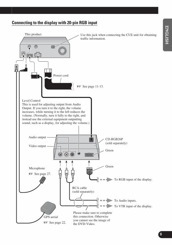
Use this jack when connecting the CUE unit for obtainingtraffic information.
Audio output
Video output
CD-RGB26P(sold separately)
Green
This product
Connecting to the display with 20-pin RGB input
Level ControlThis is used for adjusting output from AudioOutput. If you turn it to the right, the volumeincreases, while turning it to the left reduces thevolume. (Normally, turn it fully to the right, andinstead use the external equipment outputtingsound, such as a display, for adjusting the volume.)
Green
Please make sure to completethis connection. Otherwiseyou cannot see the image ofthe DVD-Video.
RCA cable(sold separately)
To RGB input of the display.
To Audio inputs.
To VTR input of the display.
Microphone
☞ See page 27.
GPS aerial
☞ See page 22.
☞ See page 11-13.
Power cord
CRD3650A_inst_001_030_Eng 4/15/02 2:17 PM Page 9

9
Connecting the System
ENG/MASTER 96 10
Connecting the System (In case of a display sold in the market)
Use this jack when connecting theCUE unit for obtaining traffic informa-tion.
Video output
Level ControlThis is used for adjusting output from Audio Output. Ifyou turn it to the right, the volume increases, while turningit to the left reduces the volume. (Normally, turn it fully tothe right, and instead use the external equipment out-putting sound, such as a display, for adjusting the vol-ume.)
Audio output
RCA cable (sold separately)
CD-RGB26P(Sold Separately)
Microphone
☞ See page 27.
GPS aerial
☞ See page 22.
Green
Green
Power cord
☞ See pages 11-13.
CRD3650A_inst_001_030_Eng 4/15/02 2:17 PM Page 10

10
EN
GLIS
HES
PA
ÑO
LD
EU
TS
CH
FR
AN
ÇA
ISIT
ALIA
NO
NED
ER
LAN
DS
ENG/MASTER 9611
Voice GuidanceSpeaker with infraredsensor < ex.CD-TS36 >(Sold Separately)
To Video inputTo Audio input
In order to output the image (RGB image) from RCA Video output (yellow)when performing navigation, switching the image output is required.
1. Park your car in a safe place, and pull the side brake.
2. Turn the power of the main unit off (cut off the engine).
3. While pressing (AUDIO) button on the bottom left of thenumeric keypad of the Remote Controller, turn the ACC on(start the engine). Keep pressing the (AUDIO) button untilthe image is displayed on the screen.
Image output is switched, as the image of the navigation (RGB image) is outputfrom RCA Video output, and the image is displayed on the screen.
Display with RCAinput jacks
CRD3650A_inst_001_030_Eng 4/15/02 2:17 PM Page 11

12
11
Connecting the System
ENG/MASTER 96
Connecting the power cord (1)
Connector
Speed detection circuit lead
Car injection computer
Connection method
Pass the extension cordand the lead for thespeed detection circuitthrough this hole.
Clamp firmly withneedle-nosed pliers.
Close the cover.
Note: The position of the speeddetection circuit depends on the carmodel. For details, consult the rele-vant documents from Pioneer.When making connections for amodel not listed in those docu-ments or for which connection tothe speed detection circuit is toodifficult, connect the separatelysold ND-PG1 speed pulse genera-tor to the pink lead.
Note: The position of the parkingbrake switch depends on the carmodel. For details, consult the carowner’s manual or dealer.
Connection method
Clamp the parking brakeswitch power supply sidelead.
Clamp firmly with needle-nosed pliers.
Power supply side
Ground side
Parking brake switch
Pink (CAR SPEED SIGNAL INPUT)The navigation system is connected here to detect the distance thecar travels. Always connect the car’s speed detection circuit or theND-PG1 speed pulse generator, sold separately. Failure to makethis connection will increase in the location display.
WARNING: IMPROPER CONNECTION MAY RESULT INSERIOUS DAMAGE OR INJURY INCLUDING ELE-CRICAL SHOCK, AND INTERFERENCE WITH THEOPERATION OF THE CAR’S ANTILOCK BRAKING SYS-TEM, AUTOMATIC TRANSMISSION AND SPEEDMETERINDICATION.
LightgreenUsed to detect the ON/OFF status of the parking brake. This leadmust be connected to the power supply side of the parking brakeswitch. If this connection is made incorrectly or omitted, cer-tain functions of your navigation system will be unusable.
CRD3650A_inst_001_030_Eng 4/15/02 2:17 PM Page 12

13
12
EN
GLIS
HES
PA
ÑO
LD
EU
TS
CH
FR
AN
ÇA
ISIT
ALIA
NO
NED
ER
LAN
DS
ENG/MASTER 96
Note:Cords for this product and those for otherproducts may be different colors even if theyhave the same function. When connecting thisproduct to another product, refer to the sup-plied Installation manuals of both productsand connect cords that have the same func-tion.
This product
Power cord
Black, Orange/white, Red, Yellow
☞ See Page 13.
Yellow/blackWhen combining this navigation unit with a Pioneer car stereo,if the car stereo has yellow/black leads, connect them to thoseleads. In this way, when the guidance audio is output and when you operate the system by voice, the car stereo is automatically muted to reduce the car stereo volume.
Connection method
Clamp the backup lamplead.
Clamp firmly with needle-nosed pliers.
Backup lamp lead.
Fuse resistor
Check the position of your car’s backuplamp (the one that lights up when theshift lever is in reverse [R]) and find thebackup lamp lead in the trunk.
Purple/white (REVERSEGEAR SIGNAL INPUT)This is connected so that the navigation system candetect whether the car is moving forwards or back-wards. Connect the purple/white lead to the leadwhose voltage changes when the shift lever is putin reverse. Unless connected, the sensor may notdetect your car traveling forward/backward proper-ly, and thus the position of your car detected by thesensor may be misaligned from the actual position.
Note: When you use the ND-PG1 speed pulse gen-erator (sold separately), please make sure to con-nect it.
CRD3650A_inst_001_030_Eng 4/15/02 2:17 PM Page 13

14
13
Connecting the System
ENG/MASTER 96
Connecting the power cord (2)
This product
YellowTo the terminal always supplied with power regardless ofignition switch position.
Fuse holder (7.5 A)
RedTo the electric terminal controlled by the ignition switch(12 V DC) ON/OFF.Do not connect this lead to power source terminals towhich power is continuously supplied. If the lead isconnected to such terminals, the battery may be drained.
Orange/whiteTo lighting switch terminal.
BlackTo car (metal) body. To keep electromagnetic noise from the car body out of the navigation system, attach this lead near the main unit.
Fuse resistor
Fuse resistor
Yellow/black, Purple/white, Pink, Lightgreen
Note: When replacing the fuse, besure to use only a fuse of the ratingprescribed on the fuse holder.
Power cord
See pages 11-12.
Note: The yellow, red, and orange/white leads should be connected to the opposite side of the fusebox terminals from the battery.
☞
Note:Cords for this product and those for other productsmay be different colors even if they have the samefunction. When connecting this product to anotherproduct, refer to the supplied Installation manualsof both products and connect cords that have thesame function.
CRD3650A_inst_001_030_Eng 4/15/02 2:17 PM Page 14

15
Installation
14
EN
GLIS
HES
PA
ÑO
LD
EU
TS
CH
FR
AN
ÇA
ISIT
ALIA
NO
NED
ER
LAN
DS
ENG/MASTER 96
CAUTION• Certain state laws may prohibit or restrict the placement and use of this sys-
tem in your car. Please comply with all applicable laws and regulationsregarding the use, installation, and operation of your navigation system.
• Pioneer does not recommend that you install or service your DVD navigationunit yourself. Installing or servicing the product may expose you to risk ofelectric shock or other hazards. Refer all installation and servicing of yournavigation unit to authorized Pioneer service personnel.
• Never install the unit in places where:* It could injure the driver or passengers if the car stops suddenly.* It may interfere with the driver’s operation of the car, such as on the floor
in front of the driver’s seat.
• Make sure there is nothing behind the dashboard or paneling when drillingholes in them. Be careful not to damage fuel lines, brake lines or powercables.
• When using screws, do not allow them to come into contact with any electri-cal lead. Vibration may damage wires, leading to a short circuit or otherdamage to the car.
• To ensure proper installation, use the supplied parts in the manner specified.If any parts other than the supplied ones are used, they may damage internalparts of the unit or they may work loose and the unit may come off.
• It is extremely dangerous to allow the GPS antenna lead or microphone leadto become wound around the steering column or shift lever. Be sure to installthe unit in such a way that it will not obstruct driving.
• Make sure that leads cannot get caught in a door or the sliding mechanism ofa seat, resulting in a short circuit.
• Please confirm the proper function of your car’s other equipment followinginstallation of the DVD navigation unit.
CRD3650A_inst_001_030_Eng 4/15/02 2:17 PM Page 15

16
To guard against electromagnetic interference• In order to prevent interference, set the following items as far as possible from the main
unit of this Navigation System, other cables or leads:- TV antenna and antenna lead - FM, AM antenna and its lead - GPS antenna and its lead
In addition you should lay each antenna lead as far as possible from other antenna leads.Do not bind them together, lay them together, or cross them. Such electromagnetic noise would increase the error for the location display.
Before installing and fixing• Consult with your nearest dealer if installation requires the drilling of holes or other mod-
ifications of the car.• Before finally installing the unit, connect the wiring temporarily, making sure it is all
connected up properly, and the unit and the system work properly.• For the installation and attachment of the Connection box, consult the shop where you
bought the product, or your dealer.
Before using the adhesive tape• Make sure the surface is free of moisture, dust, grime, oil, etc. before affixing the tape.
15
Installation
ENG/MASTER 96
CRD3650A_inst_001_030_Eng 4/15/02 2:17 PM Page 16

17
16
EN
GLIS
HES
PA
ÑO
LD
EU
TS
CH
FR
AN
ÇA
ISIT
ALIA
NO
NED
ER
LAN
DS
ENG/MASTER 96
Installing the main unit
Installation notes• Do not install the main unit in places where it may become subject to high temperatures
or humidity, such as:* Places close to a heater outlet.* Places exposed to direct sunlight, such as on top of the dashboard or the rear shelf.* Places that may be splashed by rain, for example close to the door.
• The installation strength will depend on the car model and the installation position.Choose a position where the main unit can be firmly installed, and install it securely.If the main unit is not securely fastened, the errors in location display will be greater.
• Do not install the main unit on the board covering the spare tire or other places whichare subject to vibration.
• When the main unit is installed under a front seat, ensure that it does not obstruct thesliding action of the seat.
• Do not install the main unit anywhere that cargo or the like will get on it. Strongmechanical shock to the main unit would increase the errors in location display.
• Avoid installing the main unit in places where it will interfere with loading and unload-ing of the spare tire, jack, tools, etc.
• Check that a disc or a PC card can be ejected with the main unit installed.• Install the main unit on a surface within +30 degrees to -15 degrees tolerance (within
five degrees to the left or right of your car’s direction of travel). A surface tilted morethan this would increase the errors in location display.
• Do not install the main unit vertically. Installing it this way can cause it to functionimproperly.
5°
5°
30°
15°
CRD3650A_inst_001_030_Eng 4/15/02 2:17 PM Page 17
18
17
Installation
ENG/MASTER 96
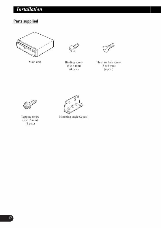
Parts supplied
Main unit Binding screw(5 × 6 mm)
(4 pcs.)
Flush surface screw(5 × 6 mm)
(4 pcs.)
Mounting angle (2 pcs.)Tapping screw(6 × 16 mm)
(4 pcs.)
CRD3650A_inst_001_030_Eng 4/15/02 2:17 PM Page 18
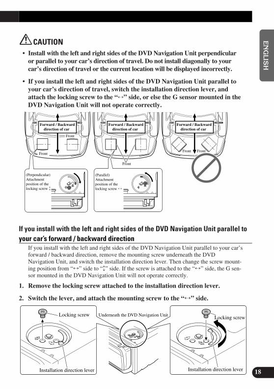
CAUTION• Install with the left and right sides of the DVD Navigation Unit perpendicular
or parallel to your car’s direction of travel. Do not install diagonally to yourcar’s direction of travel or the current location will be displayed incorrectly.
• If you install the left and right sides of the DVD Navigation Unit parallel toyour car’s direction of travel, switch the installation direction lever, andattach the locking screw to the “↔” side, or else the G sensor mounted in theDVD Navigation Unit will not operate correctly.
If you install with the left and right sides of the DVD Navigation Unit parallel toyour car’s forward / backward direction
If you install with the left and right sides of the DVD Navigation Unit parallel to your car’sforward / backward direction, remove the mounting screw underneath the DVDNavigation Unit, and switch the installation direction lever. Then change the screw mount-ing position from “↔” side to “↕” side. If the screw is attached to the “↔” side, the G sen-sor mounted in the DVD Navigation Unit will not operate correctly.
1. Remove the locking screw attached to the installation direction lever.
2. Switch the lever, and attach the mounting screw to the “↔” side.
Locking screw
Installation direction lever
Underneath the DVD Navigation Unit Locking screw
Installation direction lever
Front
Front Front
Front
Front
(Perpendicular)Attachment position of the locking screw ↕
(Parallel) Attachment position of the locking screw ↔
Forward / Backward direction of car
Forward / Backward direction of car
Forward / Backward direction of car
18
EN
GLIS
HES
PA
ÑO
LD
EU
TS
CH
FR
AN
ÇA
ISIT
ALIA
NO
NED
ER
LAN
DS
ENG/MASTER 9619
CRD3650A_inst_001_030_Eng 4/15/02 2:17 PM Page 19

20
19
Installation
ENG/MASTER 96
When installing the main unit inside the trunk, on the floor under a seat, etc.,using tapping screws
1. Fit mounting angles to the sides of the main unit.
Use the following holes onthe mounting angles.
Mounting angle
Binding screw or flush surface screw
CRD3650A_inst_001_030_Eng 4/15/02 2:17 PM Page 20

2. Fix to the floor with tapping screws.
CAUTION• Before drilling any mounting holes, confirm that the screws will not interfere
with any of the car’s operating systems (such as the fuel line, brake lines,electrical wiring, etc.).
20
EN
GLIS
HES
PA
ÑO
LD
EU
TS
CH
FR
AN
ÇA
ISIT
ALIA
NO
NED
ER
LAN
DS
ENG/MASTER 9621
Tapping screw
Drill 4 to 4.5 mm diameter holes.
Floor
CRD3650A_inst_001_030_Eng 4/15/02 2:17 PM Page 21

21
Installation
DIN Rear-mount: Installation using the screw holes on the side of the unit
• Fastening the unit to the factory radio mounting bracket.Select a position where the screw holes of the bracket andthe screw holes of the head unit become aligned (are fit-ted), and tighten the screws at 2 places on each side. Use either binding screws (5 × 6 mm) or flush surfacescrews (5 × 6 mm), depending on the shape of the screwholes in the bracket.
ENG/MASTER 96 22
Screw
Dashboard or Console
Mounting bracket
CRD3650A_inst_001_030_Eng 4/15/02 2:17 PM Page 22

Installing the GPS antenna
CAUTION• Do not cut the GPS antenna lead to shorten it or use an extension to make it
longer. Altering the antenna cable could result in a short circuit.
Installation notes
• When installing the GPS antenna inside the car, be sure to use the metal sheet providedwith your system. If this is not used, the reception sensitivity will be poor.
• Do not cut the accessory metal sheet. This would reduce the sensitivity of the GPSantenna.
• Take care not to pull the antenna lead when removing the GPS antenna. The magnetattached to the antenna is very powerful, and the lead may become detached.
• The GPS antenna is installed with a magnet. When installing the GPS antenna, be care-ful not to scratch the car body.
• When installing the GPS antenna on the outside of the car, always put it in the car whengoing through an automatic car wash. If it is left on the outside it may be knocked offand scratch the car body.
• Do not paint the GPS antenna, as this may affect its performance.
Dashboard
Roof Rear shelf
Trunk lid
• The antenna should be installed on alevel surface where radio waves willbe blocked as little as possible. Radiowaves cannot be received by the anten-na if reception from the satellite isblocked.Installation on the car roof or trunk lidis recommended to enable best recep-tion.
22
EN
GLIS
HES
PA
ÑO
LD
EU
TS
CH
FR
AN
ÇA
ISIT
ALIA
NO
NED
ER
LAN
DS
ENG/MASTER 9623
CRD3650A_inst_001_030_Eng 4/15/02 2:17 PM Page 23

23
Installation
Parts supplied
When installing the antenna inside the car (on the dashboard or rear shelf)Affix the metal sheet on as level a surface as possible where the GPS antenna faces outsidethe window. Place the GPS antenna on the metal sheet. (The GPS antenna is fastenedwith its magnet.)
Note:• When attaching the metal sheet, do not cut it into small pieces.• Some models use window glass that does not allow signals from GPS satellites to pass through. On
such models, install the GPS antenna on the outside of the car.
GPS antenna
Make sure the surface isfree of moisture, dust,grime, oil, etc., beforeaffixing the metal sheet.
Note: The metal sheetcontains a strong adhesiveand may leave a mark onthe dashboard if it isremoved.
ClampsUse clamps to secure thelead where necessary insidethe car.
Metal SheetPeel off the protective sheeton the rear.
Waterproof padClamp (5 pcs.)Metal sheetGPS antenna
ENG/MASTER 96 24
CRD3650A_inst_001_030_Eng 4/15/02 2:17 PM Page 24

When installing the antenna outside the car (on the body)Put the GPS antenna in a position as level as possible, such as on the roof or trunk lid. (TheGPS antenna is fastened with a magnet.)
ClampsUse clamps to securethe lead wherenecessary inside thecar.
ClampsUse clamps to secure thelead where necessary insidethe car.
GPS antenna
When routing the lead in from the top of thedoor
Make a U-shaped loop in the leadon the outside to prevent rainwaterfrom flowing along the lead into theinterior of the car.
When routing the lead in from inside the trunk
Waterproof padMake sure the waterproof padcontacts the top of the rubberpacking.
Rubber packing
Make a U-shaped loop in thelead outside the rubberpacking to prevent rainwaterfrom flowing along the leadinto the interior of the car.
24
EN
GLIS
HES
PA
ÑO
LD
EU
TS
CH
FR
AN
ÇA
ISIT
ALIA
NO
NED
ER
LAN
DS
ENG/MASTER 9625
CRD3650A_inst_001_030_Eng 4/15/02 2:17 PM Page 25

25
Installation
Installing the Remote controller
Parts supplied
Loading the batteriesRemove the battery cover, and insert two alkaline (UM-4, AAA, LR03, 1.5V) batteries.For details, see “Hardware Manual”.
CAUTION• Take care to insert the batteries the right way round as shown by the + and -
marks in the diagram.• Do not mix new batteries with old.• Do not mix different types of batteries. Even batteries of the same size may
have different voltages.• If the Remote Controller will be out of use for a long period, remove the bat-
teries.• If a battery leaks, completely clean any liquid or deposits from the battery
compartment before inserting new batteries.• The supplied batteries cannot be recharged.• We recommend using alkaline batteries as replacements.• When disposing of used batteries, please comply with governmental regula-
tions or environmental public institutional rules that apply in yourcountry/area.
Remote controller handling notes• Always keep the remote controller protected from direct sunlight or high temperatures.
Leaving the remote controller in places exposed to direct sunlight or high temperaturesfor long periods of time may cause deformation, discoloration or malfunction.
• Replace the batteries when the remote controller’s performance deteriorates.
Double-sided tape(large)
HolderAlkaline battery(UM-4, AAA, LR03 1.5 V) (2 pcs.)
Remote controller
ENG/MASTER 96 26
CRD3650A_inst_001_030_Eng 4/15/02 2:17 PM Page 26

When installing with double-sided tapeAttach the Holder using the double-sided tape (large) included in the set.
When attaching horizontally
When attaching with elevated position
26
EN
GLIS
HES
PA
ÑO
LD
EU
TS
CH
FR
AN
ÇA
ISIT
ALIA
NO
NED
ER
LAN
DS
ENG/MASTER 9627
Remote Controller
Remove(not to be used)
Double-sided tape (large)
Double-sided tape (large)
Holder
Remote Controller
Remove
Holder
CRD3650A_inst_001_030_Eng 4/15/02 2:17 PM Page 27

27
Installation
Installing the microphone
Installation notes• Install the microphone in a position and orientation that will enable it to pick up well the
voice of the person operating the system by voice.
Parts supplied
Clamp(5 pcs.)
Double-sided tape(small)
Microphone clipMicrophone
ENG/MASTER 96 28
CRD3650A_inst_001_030_Eng 4/15/02 2:17 PM Page 28

29
28
EN
GLIS
HES
PA
ÑO
LD
EU
TS
CH
FR
AN
ÇA
ISIT
ALIA
NO
NED
ER
LAN
DS
ENG/MASTER 96
When installing the microphone on the sun visor
1. Install the microphone on the microphone clip.
2. Install the microphone clip on the sun visor.With the sun visor up, install the microphone clip. (Lowering the sun visor reduces therecognition rate for voice operations.)
Microphone clip
ClampsUse clamps to secure thelead where necessary insidethe car.
Microphone
Microphone clip
CRD3650A_inst_001_030_Eng 4/15/02 2:17 PM Page 29

30
29
Installation
When installing the microphone on the steering column
1. Install the microphone on the microphone clip.
2. Install the microphone clip on the steering column.
CAUTION• It is extremely dangerous to allow the microphone lead to become wound
around the steering column or shift lever. Be sure to install the unit in such away that it will not obstruct driving.
ClampsUse clamps to secure thelead where necessary insidethe car.
Double-sided tape
Install the microphone clip onthe rear side of the steeringcolumn.
Fit the microphone lead intothe groove.
Microphone
Microphone clip
ENG/MASTER 96
CRD3650A_inst_001_030_Eng 4/15/02 2:17 PM Page 30

After installing the unit
1. Reconnecting the battery.First, double-check that all connections are correct and that the unit is installed correctly.Reassemble all car components that you previously removed. Then reconnect the negative(–) cable to the negative (–) terminal of the battery.
2. Start the engine.
3. Press the reset button on the main unit.Press the reset button on the main unit using a pointed object such as the point of a pen.
4. Set the navigation system.Set the navigation system as explained in the “Operation manual”.
30
EN
GLIS
HES
PA
ÑO
LD
EU
TS
CH
FR
AN
ÇA
ISIT
ALIA
NO
NED
ER
LAN
DS
ENG/MASTER 9631
Reset button
CRD3650A_inst_001_030_Eng 4/15/02 2:17 PM Page 31

1
INFORMATION IMPORTANTE
A PROPOS DE VOTRE UNITÉ DE NAVIGATION DVD ET DE CE MANUEL
• Cette unité de navigation DVD Pioneer est destinée uniquement à vous aider dansla conduite de votre véhicule. En aucun cas, elle n’autorise un relâchement devotre attention, de votre jugement et de votre vigilance pendant la conduite.
• N’utilisez pas cette unité de navigation DVD pour des services d’urgence commedes hôpitaux ou des postes de police. Toutes les installations de service d’urgencene se trouvent pas dans les données cartographiées.
• N’utilisez PAS le système de navigation automobile si son emploi détourne votreattention et empêche un maniement sûr de votre véhicule. Respectez toujours lesrègles du code de la route et conformez-vous à toutes les réglementationsroutières en vigueur.
• Les lois de certains états peuvent limiter l’installation et l’emploi des systèmes denavigation dans les voitures. Conformez-vous à toutes les lois et réglementationsen vigueur sur l’installation et le fonctionnement de votre système de navigation.
• Ce manuel vous explique comment installer cette unité de navigation DVD dansvotre voiture. L’utilisation proprement dite de l’unité de navigation DVD estexpliquée dans le “Manuel de fonctionnement” séparé, livré avec le système.
ENG/MASTER 96 32
CRD3650A_inst_032_061_FRE 4/15/02 2:18 PM Page 32

33
IMPORTANTES MESURES DESECURITE .............................................. 3
VEUILLEZ LIRE TOUTES LES EXPLICATIONS RELATIVES À VOTRE UNITÉ DE NAVIGATION DVDET LES CONSERVER POUR VOUS YRÉFÉRER ÉVENTUELLEMENT PAR LA SUITE .......................................... 3
Branchement du système ........................ 5ATTENTION .................................................... 5
- Avant de raccorder l’appareil- Pour éviter des dégâts- Pièces fournies
Branchement du système ....................................7- Branchement à l’écran à l’aide du
câble 26 broches RVB d’entrée (AVH-P6400CD, AVH-P6400, etc.)
- Branchement à l’écran à l’aide du câble 20 broches RVB d’entrée
Branchement du système (dans le cas d’un écran disponible sur le marché) .................. 9
Branchement du cordon d’alimentation (1) .... 11Branchement du cordon d’alimentation (2) .... 13
Installation ................................................ 14ATTENTION .................................................. 14Pour protéger le système de navigation
contre les parasites électromagnétiques .... 15Avant un branchement définitif ...................... 15Avant d’employer le ruban adhésif .................. 15Installation de l’unité principale ...................... 16
- Remarques sur l’installation- Pièces fournies- ATTENTION- Si vous installez avec les côtés gauche et
droit de l’unité de navigation DVD parallèlement au sens de déplacement de votre véhicule
- Installation dans le coffre, sur le tapis, sous un siège, etc. avec les vis taraudeuses
- ATTENTION- Montage DIN arrière : Installation en
utilisant les trous de vis sur les côtés de l’appareil
Installation de l’antenne GPS .......................... 22- ATTENTION- Remarques sur l’installation- Pièces fournies- Installation de l’antenne dans le véhicule
(sur planche de bord ou lunette arrière)- Installation de l’antenne à l’extérieur du
véhicule (sur la carrosserie)Installation de la télécommande ...................... 25
- Pièces fournies- Insertion des piles- ATTENTION- Remarques sur le maniement de la
télécommande- En cas d’installation avec bande adhésive
double faceInstallation du microphone .............................. 27
- Remarques sur l’installation- Pièces fournies- Installation du microphone sur le
pare-soleil- Installation du microphone sur la
colonne de direction- ATTENTION
Après installation de l’unité .................. 30
2
EN
GLIS
HFR
AN
ÇA
ISD
EU
TS
CH
FR
AN
ÇA
ISIT
ALIA
NO
NED
ER
LAN
DS
ENG/MASTER 96
Table des matières
CRD3650A_inst_032_061_FRE 4/15/02 2:18 PM Page 33

34ENG/MASTER 96
IMPORTANTES MESURES DE SECURITE
3
VEUILLEZ LIRE TOUTES LES EXPLICATIONS RELATIVES À VOTRE UNITÉ DE NAVIGATION DVD ET LES CONSERVER POUR VOUS Y RÉFÉRER ÉVENTUELLEMENT PAR LA SUITE
1. Lisez attentivement toute cette brochure avant d’installer votre unité de naviga-tion DVD.
2. Conservez ce manuel à portée de la main pour vous y référer ultérieurement.
3. Tenez compte de tous les avertissements formulés dans ce manuel et respectezsoigneusement les consignes.
4. Cette unité est destinée uniquement à vous aider dans la conduite de votrevéhicule. En aucun cas, elle n’autorise un relâchement de votre attention, de votrejugement et de votre vigilance pendant la conduite. N’utilisez PAS l’unité de nav-igation DVD si son emploi détourne votre attention et empêche un maniement sûrde votre véhicule. Respectez toujours les règles du code de la route et conformez-vous à toutes les réglementations routières en vigueur.
5. Les lois de certains états peuvent limiter l’installation et l’emploi des systèmes denavigation dans les voitures. Conformez-vous à toutes les lois et réglementationsen vigueur sur l’installation et le fonctionnement de votre système de navigation.
6. Dans certaines circonstances, cette unité de navigation DVD peut afficher desinformations erronées à propos de la position de votre véhicule, de la distance desobjets affichés sur l’écran et des directions de la boussole. En outre, le systèmecomporte certaines limitations, telles que l’incapacité de signaler les rues à sensunique, les restrictions temporaires à la circulation et les zones où la circulationpeut devenir dangereuse. Veuillez faire appel à votre propre jugement en fonctionde la situation réelle.
CRD3650A_inst_032_061_FRE 4/15/02 2:18 PM Page 34

35
4
EN
GLIS
HFR
AN
ÇA
ISD
EU
TS
CH
FR
AN
ÇA
ISIT
ALIA
NO
NED
ER
LAN
DS
ENG/MASTER 96
7. Comme tout autre accessoire de l’habitacle, l’unité de navigation DVD ne doitpas détourner votre attention et nuire à la sécurité de la conduite. Si vous éprou-vez des difficultés à utiliser le système ou à lire l’écran, effectuez les réglagesnécessaires après vous être garé dans un endroit sûr.
8. N’essayez pas d’installer ou d’entretenir vous-même votre unité de navigationDVD. L’installation et l’entretien effectués par un personnel non formé et noncompétent en équipements électroniques et accessoires pour automobiles peutêtre dangereux car il y a risque d’électrocution et d’autres accidents.
9. Veillez à attacher toujours votre ceinture de sécurité sur la route. En cas d’acci-dent, le port de la ceinture peut réduire considérablement la gravité des blessures.
CRD3650A_inst_032_061_FRE 4/15/02 2:18 PM Page 35

5
Branchement du système
ATTENTION• Pioneer déconseille d’installer ou d’entretenir vous-même votre unité de
navigation DVD. Ces travaux comportent des risques d’électrocution etd’autres dangers. Confiez l’installation et l’entretien à un personnel de ser-vice Pioneer qualifié.
• Immobilisez tous les fils avec des colliers ou des serre-câbles. Ne laissezaucun fil à nu.
• Ne forez pas un orifice vers le compartiment du moteur afin de raccorder lefil jaune de l’appareil sur la batterie du véhicule car les vibrations du moteurpourraient à la longue abîmer l’isolation du fil au point de passage entrel’habitable et le compartiment du moteur. Veillez tout particulièrement àbien immobiliser le fil à ce point.
• Une situation très dangereuse pourrait se présenter si le câble d’antenneGPS ou le fil du microphone devait s’enrouler autour de la colonne de direc-tion ou du levier de vitesses. Veillez à installer l’appareil de telle sorte querien ne fasse obstacle à la conduite.
• Assurez-vous qu’aucun fil ou conducteur ne fasse obstacle aux pièces mobilesdu véhicule, telles que le levier de vitesses, le frein à main ou le mécanisme deréglage de la position des sièges.
• Ne cheminez pas les fils à des endroits potentiellement très chauds car unéchauffement de leur isolant peut les endommager et entraîner un court-cir-cuit.
• Ne coupez pas le câble de l’antenne GPS et n’utilisez pas un prolongateurpour l’allonger car une telle modification pourrait provoquer un court-cir-cuit.
• Ne court-circuitez pas les fils car le circuit de protection ne fonctionneraitplus correctement.
• N’alimentez jamais d’autres appareils électroniques en coupant la gaineisolante du cordon d’alimentation de l’unité de navigation DVD et en y effec-tuant des raccords, car la capacité du cordon serait dépassée, ce qui provo-querait une surchauffe.
ENG/MASTER 96 36
CRD3650A_inst_032_061_FRE 4/15/02 2:18 PM Page 36

Avant de raccorder l’appareil• Cet appareil est destiné aux véhicules avec une batterie de 12 V, avec pôle négatif à la
masse. Avant de l’installer dans un véhicule de loisir, un camion ou un car, vérifiez latension de la batterie.
Pour éviter des dégâts
Pièces fournies
Câble 26 broches RVBConnecteurCordon d’alimentation
Pas de position ACCPosition ACC
ONS
TA
R
T
OFF
ACCON
STA
R
T
OFF
• Pour débrancher un connecteur, tirezsur le connecteur proprement dit et passur son fil, car il pourrait en êtrearraché.
• Si cette unité est installée dans unvéhicule dont le contacteur d’allumagen’a pas de position ACC (accessoire),le fil rouge de l’unité doit être connec-té à une borne couplée aux opérationsde marche/arrêt du contacteur d’al-lumage. Sinon, la batterie du véhiculepeut se décharger lorsque le véhiculen’est pas utilisé pendant plusieursheures.
• Pour éviter les courts-circuits, recou-vrez les fils déconnectés par du rubanisolant.
• Afin d’éviter tout risque de court-cir-cuit, débranchez le câble de la bornenégative (-) de la batterie avant decommencer la pose.
6
EN
GLIS
HFR
AN
ÇA
ISD
EU
TS
CH
FR
AN
ÇA
ISIT
ALIA
NO
NED
ER
LAN
DS
ENG/MASTER 9637
CRD3650A_inst_032_061_FRE 4/15/02 2:18 PM Page 37

38
Branchement du système
Branchement à l’écran à l’aide du câble 26 broches RVB d’entrée (AVH-P6400CD, AVH-P6400, etc.)
7
Branchement du système
ENG/MASTER 96
Utilisez cette prise pour connecter l’unité CUEafin d’obtenir les informations sur le trafic.
Cordon d’alimentation
Ce produit
☞ Cf. pages 11-13.
(Ex. AVH-P6400CD, AVH-P6400)
Microphone
☞ Cf. page 27.
Antenne GPS
☞ Cf. page 22.
Câble 26 broches RVB(fourni)
6m
Lors de la réinitialisation de unité principale central AVLorsque vous appuyez sur le bouton deréinitialisation de unité principale AV alorsque le système de navigation et unité principale AV (AVH-P6400CD, AVH-P6400) sont combinés, veillez à ceque la clé de contact ne soit pas sur ACC. Si le bouton de réinitialisation est enfoncéalors que la clé de contact est sur ACC, celarisque d’entraîner un dysfonctionnement.
CRD3650A_inst_032_061_FRE 4/15/02 2:18 PM Page 38

39
8
EN
GLIS
HFR
AN
ÇA
ISD
EU
TS
CH
FR
AN
ÇA
ISIT
ALIA
NO
NED
ER
LAN
DS
ENG/MASTER 96
Branchement à l’écran à l’aide du câble 20 broches RVB d’entrée
Veillez à établir cette connexion.Autrement, vous ne pourrez pasvoir l’image sur l’écran DVDvideo.
Sortie audio
Sortie vidéo
Microphone
☞ Cf. page 27.
Antenne GPS
☞ Cf. page 22.
Câble RCA(vendu séparément)
Vert
Utilisez cette prise pour connecter l’unité CUEafin d’obtenir les informations sur le trafic.
Ce produit
Cordon d’alimentation
☞ Cf. pages 11-13.
Commande de niveauCette commande est utilisée pour régler la sortieaudio. Tournez vers la droite pour augmenter, ourespectivement vers la gauche pour diminuer levolume. (Normalement, tournez-la complètementvers la droite et réglez plutôt directement le son desortie de l’équipement externe, tel que l’écran,pour régler le volume.)
CD-RGB26P(fourni avec l’écran)
Vert
A l’entrée RVB del’écran.
Vers les entrées audio.
Vers l’entrée VTR del’écran.
CRD3650A_inst_032_061_FRE 4/15/02 2:18 PM Page 39

9
Branchement du système
ENG/MASTER 96 40
Branchement du système (dans le cas d’un écran disponible sur le marché)
Utilisez cette prise pour connecter l’u-nité CUE afin d’obtenir les informa-tions sur le trafic.
Sortie vidéo
Commande de niveauCette commande est utilisée pour régler la sortie audio.Tournez vers la droite pour augmenter, ou respectivementvers la gauche pour diminuer le volume. (Normalement,tournez-la complètement vers la droite et réglez plutôtdirectement le son de sortie de l’équipement externe, telque l’écran, pour régler le volume.)
Sortie audio
Câble RCA (vendu séparément)
CD-RGB26P(fourni avec l’écran)
Microphone
☞ Cf. page 27.
Antenne GPS
☞ Cf. page 22.
Vert
Vert
Cordon d’alimentation
☞ Cf. pages 11-13.
CRD3650A_inst_032_061_FRE 4/15/02 2:18 PM Page 40

10
EN
GLIS
HFR
AN
ÇA
ISD
EU
TS
CH
FR
AN
ÇA
ISIT
ALIA
NO
NED
ER
LAN
DS
ENG/MASTER 9641
Haut parleur de guidagevocal avec capteurinfrarouge < ex. CD-TS36 >(Vendu séparément)
Vers l’entrée vidéoVers les entrées audio
Pour obtenir l’image (image RGB) sur la sortie vidéo RCA (jaune) lorsque lafonction de navigation est activée, il faut commuter la sortie d’image.
1. Garez votre véhicule en respectant les règles de sécurité et tirez lefrein de stationnement.
2. Coupez l’alimentation de l’unité principale (coupez le moteur).
3. Tout en appuyant sur la touche (AUDIO) en bas à gauche duclavier numérique de la télécommande de pilotage, activez l’ACC(démarrez le moteur). Appuyez sur la touche (AUDIO) jusqu’àl’image apparaît à l’écran.
La sortie de l’image est commutée, l’image du navigateur (image RVB) provientalors de la sortie vidéo RCA, et l’image apparaît à l’écran.
Écran muni de prisesd’entrée Cinch (RCA)
CRD3650A_inst_032_061_FRE 4/15/02 2:18 PM Page 41

11
Branchement du système
Branchement du cordon d’alimentation (1)
Conducteur de circuit de détection de vitesse
Ordinateur d’injection
Connecteur
Méthode de connexion
Remarque: La position du circuitde détection de vitesse dépend dumodèle du véhicule. Pour desdétails, consultez les do-cumentsappropriés de Pioneer. Poureffectuer les connexions sur unmodèle ne figurant pas dans cesdocuments ou sur lequel lebranchement au circuit de détec-tion de vitesse est trop difficile,raccordez un générateur d’impul-sions de vitesse ND-PG1 sur lecordon de connexion rose.
Remarque: La position du contac-teur de frein à main dépend dumodèle de véhicule. Pour lesdétails, consultez le manuel de l’u-tilisateur du véhicule ou un conces-sionnaire.
Passez le cordon-rallongeet le fil pour le circuit dedétection de vitesse parce trou.
Serrez fermementavec une pince àmâchoires pointues.
Fermez le couvercle.
Immobilisez le fil d’ali-mentation du contacteur defrein à main.
Serrez fermement avec unepince à mâchoires pointues.
Méthode de connexion
Côté alimentation
Côté masse
Contacteur de frein à main
Rose (Entrée du signal de vitesse de voiture)Le système de navigation est raccordé ici afin de détecter la dis-tance parcourue par la voiture. Raccordez toujours le circuit dedétection de vitesse de la voiture ou le générateur d’impulsions devitesse ND-PG1, vendu séparément. Sans cette connexion, le risqued’erreur d’affichage de la position augmente.
AVERTISSEMENT : UNE CONNEXION INAPPROPRIEERISQUE D'ENTRAINER DES DOMMAGES SERIEUX OUDES BLESSURES DUES A UN CHOC ELECTRIQUE, DESINTERFERENCES AVEC LE FONCTIONNEMENT DU SYS-TEME DE FREINAGE ANTIBLOCAGE DU VEHICULE,AVEC LA TRANSMISSION AUTOMATIQUE ET AVEC LESINDICATIONS DU COMPTEUR DE VITESSE.
Vert clairUtilisé pour détecter l’état ON/OFF du frein à main. Ce conducteurdoit être raccordé sur l’alimentation du contacteur de frein à main.Si cette connexion est omise ou mal faite, certaines fonctions dusystème de navigation ne seront pas utilisables.

43
12
EN
GLIS
HFR
AN
ÇA
ISD
EU
TS
CH
FR
AN
ÇA
ISIT
ALIA
NO
NED
ER
LAN
DS
ENG/MASTER 96
Ce produit
Cordon d’alimentation
Noir, Orange/blanc, Rouge, Jaune
☞ Cf. page 13.
Jaune/noirAu cas où l’unité de navigation automobile est combinée à uneauto-stéréo Pioneer, si celle-ci possède des fils jaune/noir,effectuez le branchement sur ces fils. De cette façon, quand leguidage sonore est en service et lors d’une commande vocale, leson de l’auto-stéréo est automatiquement atténué et le volumesonore est réduit.
Violet/blanc (Entrée de signal de marchearrière)Cette connexion est effectuée pour que le système denavigation puisse détecter si le véhicule avance ourecule. Raccordez le cordon violet/blanc sur le cor-don dont la tension change quand le levier de vitessesest mis en marche arrière [R]. Raccordez toujours auconducteur primaire du feu de recul. S’il n’est pascorrectement connecté, le capteur peut ne pas biendétecter les mouvements de marche avant/arrière devotre véhicule, la position de votre véhicule détectéepar le capteur risque par conséquent de différer de laposition effective.
Méthode de connexion
Immobilisez le conducteur dufeu de recul.
Serrez fermement avec unepince à mâchoires pointues.
Remarque : si vous utilisez le générateur d’impul-sions de vitesse ND-PG1 (vendu séparément), veillezà effectuer le branchement. Résistance de fusible
Vérifiez la position du feu de reculde votre véhicule (celle qui s’allumequand le levier de vitesses est mis enmarche arrière [R]) et localisez leconducteur du feu de recul dans lecoffre.
Conducteur dufeu de recul.
Remarque:Les câbles de ce produit et ceux d’autresproduits peuvent fort bien ne pas être de lamême couleur bien que remplissant lamême fonction. Pour relier ce produit à unautre produit, utilisez le manuel d’installa-tion de chacun et effectuez les raccorde-ments en ne tenant compte que de la fonc-tion de chaque câble.
CRD3650A_inst_032_061_FRE 4/15/02 2:18 PM Page 43

44
13
Branchement du système
ENG/MASTER 96
Branchement du cordon d’alimentation (2)
Ce produit
Cordon d’alimentation
NoirA la carrosserie (partie métallique) du véhicule. Pouréviter que le système de navigation ne soit perturbé pardes parasites électromagnétiques, raccordez le fil prèsde l’unité principale.
Remarque: Pour remplacer unfusible, utilisez-en un neuf ayantl’ampérage indiqué sur le porte-fusibles.
Remarque: Les conducteurs jaune, rouge etorange/blanc doivent être raccordés sur le côtéopposé des bornes du boîtier à fusibles provenant dela batterie.
Porte-fusible (7.5 A)
Résistance de fusible
Résistance de fusible
Jaune/noir, Violet/blanc, Rose, Vert clair
☞ Cf. pages 11-12.
JauneA la borne toujours sous tension, quelle que soit la posi-tion de la clé de contact.
RougeA la borne électrique, contrôlée par la position ON/OFFde la clé de contact (courant continu 12 V).Ne raccordez pas ce fil sur les bornes continuellementsous tension. S’il est branché sur ces bornes, la batterieva se décharger.
Orange/blancA la borne du commutateur d’éclairage.
Remarque:Les câbles de ce produit et ceux d’autres produitspeuvent fort bien ne pas être de la même couleur bienque remplissant la même fonction. Pour relier ce pro-duit à un autre produit, utilisez le manuel d’installa-tion de chacun et effectuez les raccordements en netenant compte que de la fonction de chaque câble.
CRD3650A_inst_032_061_FRE 4/15/02 2:18 PM Page 44

45
Installation
14
EN
GLIS
HFR
AN
ÇA
ISD
EU
TS
CH
FR
AN
ÇA
ISIT
ALIA
NO
NED
ER
LAN
DS
ENG/MASTER 96
ATTENTION• Les lois de certains états peuvent interdire ou limiter l’installation et l’emploi
de ce système dans les voitures. Conformez-vous à toutes les lois et réglemen-tations en vigueur sur l’installation, l’utilisation et le fonctionnement du sys-tème de navigation.
• Pioneer déconseille d’installer ou d’entretenir vous-même votre unité de nav-igation DVD car ces travaux comportent des risques d’électrocution etd’autres dangers. Confiez l’installation et l’entretien à un personnel de ser-vice Pioneer qualifié.
• N’installez jamais l’unité dans un endroit où:* elle pourrait blesser le conducteur ou les passagers en cas d’arrêt brusque;* elle pourrait gêner les mouvements du conducteur, comme sur le plancher
devant son siège.
• Avant d’y forer des trous, assurez-vous que rien ne se trouve derrière laplanche de bord ou une cloison. Veillez à ne pas endommager les canalisa-tions de carburant, circuits de freinage ou câbles d’alimentation.
• A l’emploi de vis, faites attention à un contact éventuel avec un conducteurélectrique. Des vibrations pourraient endommager les fils et provoquer uncourt-circuit ou d’autres dégâts sur le véhicule.
• Pour que l’installation soit correcte, utilisez les pièces fournies de la manièrespécifiée. L’emploi de pièces différentes peut endommager les composantsintérieurs de l’unité ou, en se détachant, elles peuvent provoquer la chute del’unité.
• Une situation très dangereuse pourrait se présenter si le câble d’antenneGPS ou le fil du microphone devait s’enrouler autour de la colonne de direc-tion ou du levier de vitesses. Veillez à installer l’appareil de telle sorte querien ne fasse obstacle à la conduite.
• Assurez-vous qu’aucun fil ou conducteur n’est coincé dans une porte ou lemécanisme de coulissement d’un siège, car ceci pourrait provoquer un court-circuit.
• Vérifiez le bon fonctionnement des autres équipements du véhicule aprèsl’installation de l’unité de navigation DVD.
CRD3650A_inst_032_061_FRE 4/15/02 2:18 PM Page 45

46
Pour protéger le système de navigation contre les parasites électromagnétiques
• Pour éviter tout parasite, placez les éléments suivants le plus loin possible de l’unitéprincipale de l’unité de navigation DVD, d’autres câbles ou cordons :- Antenne TV et cordon d’antenne - Antenne FM, AM et son cordon- Antenne GPS et son cordon
Placez également chaque cordon d’antenne le plus loin possible des autres cordons d’an-tenne. Ne les reliez pas ensemble, ne les assemblez pas ou ne les croisez pas. Ces parasitesaugmenteraient l’erreur d’affichage de la position du véhicule.
Avant un branchement définitif• Consultez le concessionnaire le plus proche si l’installation nécessite le percement de
trous ou toute autre modification du véhicule.• Avant de finaliser l’installation de l’appareil, connectez temporairement le câblage en
s’assurant que tout est correctement connecté et que l’appareil et le système fonction-nent correctement.
• Pour plus d’informations sur l’installation et le branchement du boîtier de connexion,consultez le point de vente où vous avez acheté le produit ou votre revendeur.
Avant d’employer le ruban adhésif• Afin de fixer le ruban adhésif, assurez-vous que l’endroit n’est ni humide ni souillé par
de la poussière ou de l’huile, etc.
15
Installation
ENG/MASTER 96
CRD3650A_inst_032_061_FRE 4/15/02 2:18 PM Page 46

47
16
EN
GLIS
HFR
AN
ÇA
ISD
EU
TS
CH
FR
AN
ÇA
ISIT
ALIA
NO
NED
ER
LAN
DS
ENG/MASTER 96
Installation de l’unité principale
Remarques sur l’installation• N’installez pas l’unité principale à un endroit où elle serait soumise à une forte tempéra-
ture ou à l’humidité, tel que:* Près d’une bouche du chauffage du véhicule.* En plein soleil, comme sur le dessus de la planche de bord ou de la lunette arrière.* Evitez un endroit où l’unité peut être mouillée par la pluie, comme près d’une porte.
• La résistance de l’installation dépend du modèle du véhicule et de la position de l’instal-lation. Choisissez un endroit où l’unité principale pourra être solidement fixée etinstallez-la convenablement. Si elle n’est pas fermement immobilisée, l’erreur d’af-fichage de la position du véhicule augmentera.
• N’installez pas l’unité principale sur le couvercle du pneu de rechange ou tout autreendroit soumis à des vibrations.
• Si l’unité principale est installée sous un siège avant, assurez-vous qu’elle ne fait pasobstacle au coulissement du siège, et qu’elle ne soit pas déplacée par les pieds des pas-sagers arrière.
• N’installez pas l’unité principale à un endroit où vous pourriez poser des bagages. Deschocs mécaniques puissants subis par l’unité principale augmenterait l’erreur d’af-fichage de la position du véhicule.
• Evitez d’installer l’unité principale à un endroit où elle gênerait l’accès au pneu derechange, au cric, à des outils, etc.
• Assurez-vous qu’un disque ou une carte PC puisse être augmenteraient de l’unité, unefois qu’elle est installée.
• L’inclinaison éventuelle de la surface d’installation de l’unité principale ne doit pasdépasser de +30 degrés à -15 degrés (à moins de cinq degrés vers la gauche ou vers ladroite du sens de déplacement de votre véhicule); faute de quoi l’erreur d’affichage de laposition du véhicule augmenterait.
• N’installez pas l’unité principale verticalement car elle ne fonctionnerait pas correcte-ment.
5°
5°
30°
15°
CRD3650A_inst_032_061_FRE 4/15/02 2:18 PM Page 47

48
Pièces fournies
17
Installation
ENG/MASTER 96
Unité principale Vis de serrage(5 × 6 mm)(4 pièces)
Vis à tête plate(5 × 6 mm)(4 pièces)
Applique de montage (2 pièces)
Vis taraudeuse(6 × 16 mm)
(4 pièces)
CRD3650A_inst_032_061_FRE 4/15/02 2:18 PM Page 48

49
18
EN
GLIS
HFR
AN
ÇA
ISD
EU
TS
CH
FR
AN
ÇA
ISIT
ALIA
NO
NED
ER
LAN
DS
ENG/MASTER 96
ATTENTION• Effectuez l’installation avec les côtés gauche et droit de l’unité de navigation
DVD perpendiculairement ou parallèlement au sens de déplacement duvéhicule. N’effectuez pas d’installation en diagonale par rapport au sens dedéplacement du véhicule sinon la position actuelle ne s’affichera pas cor-rectement.
• Si vous installez avec les côtés gauche et droit de l’unité de navigation DVDparallèlement au sens de déplacement du véhicule, basculez le levier du sensd’installation et fixez la vis de verrouillage sur le côté “↔”, sinon le capteurG monté dans l’unité de navigation DVD ne fonctionnera pas correctement.
Si vous installez avec les côtés gauche et droit de l’unité de navigation DVDparallèlement au sens de déplacement de votre véhicule
Si vous installez avec les côtés gauche et droit de l’unité de navigation DVD parallèlementau sens de déplacement de votre véhicule, retirez la vis de verrouillage située sous l’unitéde navigation DVD et basculez le levier du sens d’installation. Puis changez la position demontage de la vis du côté “↔” au côté “↕”. Si la vis est fixée au côté “↔”, le capteur Gmonté dans l’unité de navigation DVD ne fonctionnera pas correctement.
1. Retirez la vis de verrouillage fixée au levier du sens d’installation.
2. Basculez le levier et fixez la vis de verrouillage au côté “↔”.
Sens du véhicule Sens du véhicule Sens du véhicule
Avant
Avant
Avant Avant
(Perpendiculairement)Position de fixation de la vis de verrouillageCôté “↕”
(Parallèlement) Position de fixa-tion de la vis deverrouillageCôté “↔”
Vis de verrouillageVis de ver-rouillage
Sous l’unité de navigation DVD
Levier du sens d’installation Levier du sens d’installation
CRD3650A_inst_032_061_FRE 4/15/02 2:18 PM Page 49

19
Installation
Installation dans le coffre, sur le tapis, sous un siège, etc. avec les vistaraudeuses
1. Fixez les appliques de montage sur les deux côtés de l’unité principale.
ENG/MASTER 96 50
Appliques de montage
Vis de serrage ou vis à tête plate
Utilisez les trous indiquéssur les appliques de mon-tage.
CRD3650A_inst_032_061_FRE 4/15/02 2:18 PM Page 50

2. Fixez l’unité sur le plancher avec les vis taraudeuses.
ATTENTION• Avant de forer des trous, assurez-vous que les vis ne gêneront aucun organe
du véhicule (canalisations de carburant, circuits de freinage, câbles d’ali-mentation, etc.).
20
EN
GLIS
HFR
AN
ÇA
ISD
EU
TS
CH
FR
AN
ÇA
ISIT
ALIA
NO
NED
ER
LAN
DS
ENG/MASTER 9651
Plancher
Vis taraudeuse
Forez des trous de 4 à 4,5 mmde diamètre.
CRD3650A_inst_032_061_FRE 4/15/02 2:18 PM Page 51

52
21
Installation
ENG/MASTER 96
Montage DIN arrière : Installation en utilisant les trous de vis sur les côtés del’appareil
• Fixation de l’appareil au support de montage installée par le constructeur.
Choisir la position selon laquelle les orifices de vis dusupport et ceux des vis de l’appareil principal sont alignés(correspondent) et serrer les vis sur 2 endroits de chaquecôté. Utiliser l’une des vis de serrage (5 × 6 mm) ou lesvis à tête plate (5 × 6 mm), selon la forme des trous de vissur le support.
Vis
Tableau de bord ou console
Support pour le montage
CRD3650A_inst_032_061_FRE 4/15/02 2:18 PM Page 52

Installation de l’antenne GPS
ATTENTION• Ne coupez pas le câble de l’antenne GPS et n’utilisez pas un prolongateur
pour l’allonger car une telle modification pourrait provoquer un court-cir-cuit.
Remarques sur l’installation
• Si vous installez l’antenne GPS à l’intérieur du véhicule, utilisez la plaque métalliquefournie avec le système. La sensibilité de réception sera faible si elle n’est pas utilisée.
• Ne coupez pas la plaque métallique car la sensibilité de l’antenne GPS en serait réduite.• Ne tirez pas sur le câble lorsque vous déplacez l’antenne GPS, car il pourrait s’arracher
du fait qu’un aimant très puissant est fixé sur l’antenne. • L’antenne GPS s’installe grâce à un aimant. Veillez à ne pas griffer la carrosserie lors de
son installation.• Si l’antenne GPS est installée hors du véhicule, posez-la à l’intérieur lors d’un lavage
automatique; faute de quoi elle pourrait griffer la carrosserie.• Pour ne pas réduire ses performances, ne peignez pas l’antenne GPS.
• L’antenne doit être installée sur unesurface à niveau où les ondes radiosont bloquées le moins possible. Lesondes radio ne peuvent pas être cap-tées correctement par l’antenne si laréception des satellites est gênée.Une installation sur le toit ou sur lecapot du coffre est conseillée pourassurer une bonne réception.
22
EN
GLIS
HFR
AN
ÇA
ISD
EU
TS
CH
FR
AN
ÇA
ISIT
ALIA
NO
NED
ER
LAN
DS
ENG/MASTER 9653
Planche de bord
Toit Lunette arrière
Capot du coffre
CRD3650A_inst_032_061_FRE 4/15/02 2:18 PM Page 53

23
Installation
Pièces fournies
Installation de l’antenne dans le véhicule (sur planche de bord ou lunette arrière)
Fixez la plaque métallique sur une surface aussi plate que possible où l’antenne GPS seradirigée vers une vitre. Posez l’antenne GPS sur la plaque métallique. (L’antenne GPS estimmobilisée par son propre aimant.)
Remarque:• Lors de la fixation de la plaque métallique, ne la coupez pas en petits morceaux.• Certains modèles de voiture ont des vitres qui ne laissent pas passer les signaux des satellites GPS.
Dans ce cas, installez l’antenne GPS à l’extérieur du véhicule.
Coussin étancheSerre-fils (5 pièces)Plaque métalliqueAntenne GPS
ENG/MASTER 96 54
Antenne GPS
Plaque métalliqueDécollez la pellicule protectrice àl’arrière.
Afin de fixer la plaquemétallique, assurez-vous quel’endroit ne soit ni humide nisouillé par de la poussière ou del’huile, etc.
Remarque: La plaquemétallique est dotée d’unadhésif puissant qui pourraitlaisser une trace sur la plaque debord lorsqu’il est enlevé.
Serre-filsA utiliser pour fixer le fil conduc-teur aux endroits nécessaires dansle véhicule.
CRD3650A_inst_032_061_FRE 4/15/02 2:18 PM Page 54

Installation de l’antenne à l’extérieur du véhicule (sur la carrosserie)Posez l’antenne GPS sur une surface aussi plate que possible, telle que le toit ou le capotdu coffre. (L’antenne GPS est immobilisée par son propre aimant.)
24
EN
GLIS
HFR
AN
ÇA
ISD
EU
TS
CH
FR
AN
ÇA
ISIT
ALIA
NO
NED
ER
LAN
DS
ENG/MASTER 9655
Antenne GPS
Cheminement du câble sur le haut de la portière
Effectuez une boucle en U avec lecâble à l’extérieur pour éviter uneinfiltration d’eau dans l’habitacle.
Serre-filsA utiliser pour fixer lefil conducteur auxendroits nécessairesdans le véhicule.
Cheminement du fil par l’intérieur du coffre
Serre-filsA utiliser pour fixerle câble aux endroitsnécessaires dans levéhicule.
Joint caoutchouté
Coussin étancheAssurez-vous que le coussinétanche soit en contact avecle dessus du jointcaoutchouté.
Effectuez une boucle en Uavec le câble à l’extérieur dujoint caoutchouté pour éviterune infiltration d’eau dansl’habitacle.
CRD3650A_inst_032_061_FRE 4/15/02 2:18 PM Page 55

25
Installation
Installation de la télécommande
Pièces fournies
Insertion des pilesRetirez le capot du logement des piles et insérez deux piles alcalines (UM-4, AAA, LR03,1,5V). Pour plus de détail, voir “Manuel de fonctionnement ”.
ATTENTION• Veillez à insérer les piles dans la bonne position, comme illustré par les
signes + et - sur le schéma.• Ne mélangez pas des piles neuves et des piles anciennes.• Ne mélangez pas des piles de types différents. Attention : des piles de taille
identique peuvent avoir des tensions différentes.• Retirez les piles si vous n'utilisez pas le boîtier de télécommande pendant une
période prolongée.• En cas de suintement des piles, éliminez le liquide ou les dépôts dans le loge-
ment des piles avant d’en installer de nouvelles.• Les piles fournies ne sont pas rechargeables.• L’emploi de piles alcalines est recommandé.• Lorsque vous éliminez des piles usées, veuillez respecter les règles édictées
par les institutions publiques responsables de l’environnement applicablesdans votre pays ou votre région.
Remarques sur le maniement de la télécommande• Protégez toujours la télécommande contre les rayons directs du soleil et les fortes tem-
pératures. Si elle est laissée pendant longtemps en plein soleil ou dans un endroit trèschaud, elle risque d’être déformée, décolorée ou de mal fonctionner.
• Remplacez les piles quand les performances de la télécommande diminuent.
Bande adhésivedouble face(grande)
SupportPile alcaline (UM-4, AAA, LR03, 1,5 V)(2 pièces)
Télécommande
ENG/MASTER 96 56
CRD3650A_inst_032_061_FRE 4/15/02 2:18 PM Page 56

En cas d'installation avec bande adhésive double faceFixez le support à l'aide de la bande adhésive double face (large) incluse dans le néces-saire.
En cas d'installation horizontale
En cas d’installation en position élevée
26
EN
GLIS
HFR
AN
ÇA
ISD
EU
TS
CH
FR
AN
ÇA
ISIT
ALIA
NO
NED
ER
LAN
DS
ENG/MASTER 9657
Boîtier de télécommande
Support
Bande adhésive double face (large)
Boîtier de télécommande Support
Bande adhésive double face (large)
A retirer(ne doit pas être utilisée)
A retirer
CRD3650A_inst_032_061_FRE 4/15/02 2:18 PM Page 57

27
Installation
Installation du microphone
Remarques sur l’installation• Installez et orientez le microphone à un endroit où il pourra bien capter la voix de la per-
sonne qui commande le système par la voix.
Pièces fournies
Serre-fils (5 pièces)
Bande adhésive doubleface (petite)
Attache du microphoneMicrophone
ENG/MASTER 96 58
CRD3650A_inst_032_061_FRE 4/15/02 2:18 PM Page 58

Installation du microphone sur le pare-soleil
1. Fixez le microphone sur l’attache fournie.
2. Fixez l’attache du microphone sur le pare-soleil.Le pare-soleil étant relevé, fixez l’attache du microphone. (Le taux de reconnaissancevocale diminue quand le pare-soleil est abaissé.)
28
EN
GLIS
HFR
AN
ÇA
ISD
EU
TS
CH
FR
AN
ÇA
ISIT
ALIA
NO
NED
ER
LAN
DS
ENG/MASTER 9659
Microphone
Attache
Attache de microphone
Serre-filsA utiliser pour fixer le filconducteur aux endroitsnécessaires dans levéhicule.
CRD3650A_inst_032_061_FRE 4/15/02 2:18 PM Page 59

60
29
Installation
Installation du microphone sur la colonne de direction
1. Fixez le microphone sur l’attache fournie.
2. Fixez l’attache du microphone sur la colonne de direction.
ATTENTION• Une situation très dangereuse pourrait se présenter si le fil du microphone
devait s’enrouler autour de la colonne de direction ou du levier de vitesses.Veillez à cheminer le fil de manière qu’il ne fasse pas obstacle à la conduite.
ENG/MASTER 96
Microphone
Attache
Cheminez le fil du microphonedans la rainure.
Bande adhésive double face
Installez l’attache demicrophone sur l’arrièrede la colonne de direction.
Serre-filsA utiliser pour fixer le filconducteur aux endroitsnécessaires dans levéhicule.
CRD3650A_inst_032_061_FRE 4/15/02 2:18 PM Page 60
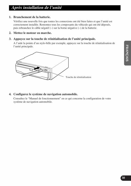
Après installation de l’unité
1. Branchement de la batterie.Vérifiez une nouvelle fois que toutes les connexions ont été bien faites et que l’unité estcorrectement installée. Remontez tous les composants du véhicule qui ont été déposés,puis rebranchez le câble négatif (–) sur la borne négative (–) de la batterie.
2. Mettez le moteur en marche.
3. Appuyez sur la touche de réinitialisation de l’unité principale.A l’aide la pointe d’un stylo-bille par exemple, appuyez sur la touche de réinitialisation del’unité principale.
4. Configurez le système de navigation automobile.Consultez le “Manuel de fonctionnement” en ce qui concerne la configuration de votresystème de navigation automobile.
30
EN
GLIS
HFR
AN
ÇA
ISD
EU
TS
CH
FR
AN
ÇA
ISIT
ALIA
NO
NED
ER
LAN
DS
ENG/MASTER 9661
Touche de réinitialisation
CRD3650A_inst_032_061_FRE 4/15/02 2:18 PM Page 61


ENG/MASTER COVER 98
PIONEER CORPORATION4-1, MEGURO 1-CHOME, MEGURO-KU, TOKYO 153-8654, JAPAN
PIONEER ELECTRONICS (USA) INC.P.O. Box 1760, Long Beach, California 90801, U.S.A.TEL: (800) 421-1404
PIONEER EUROPE NVHaven 1087, Keetberglaan 1, B-9120 Melsele, BelgiumTEL: (0) 3/570.05.11
PIONEER ELECTRONICS ASIACENTRE PTE. LTD.253 Alexandra Road, #04-01, Singapore 159936TEL: 65-472-1111
PIONEER ELECTRONICS AUSTRALIA PTY. LTD.178-184 Boundary Road, Braeside, Victoria 3195, AustraliaTEL: (03) 9586-6300
PIONEER ELECTRONICS OF CANADA, INC.300 Allstate Parkway, Markham, Ontario L3R OP2, CanadaTEL: (905) 479-4411
PIONEER ELECTRONICS DE MEXICO, S.A. de C.V.San Lorenzo 1009 3er. Piso Desp. 302Col. Del Valle Mexico, D.F. C.P. 03100TEL: 55-688-52-90
Published by Pioneer Corporation.Copyright © 2002 by Pioneer Corporation.All rights reserved.
Publication de Pioneer Corporation.Copyright © 2002 Pioneer Corporation.Tous droits de reproduction et de traductionréservés.
Printed in JapanImprimé au Japon
<CRD3650-A> UC<KKYHF/02D00001>
CRD3650A_inst_cover 4/15/02 2:22 PM Page 2