english deutsch español français sitranssitrans€¦ · · 2011-08-15english deutsch español...
TRANSCRIPT

Instruction Manual February 2009
LVS100/200sitranssitrans
English
Deutsch
Español
Français

© Siemens Milltronics Process Instruments Inc. 2009
Safety Guidelines: Warning notices must be observed to ensure personal safety as well as that of others, and to protect the product and the connected equipment. These warning notices are accompanied by a clarification of the level of caution to be observed.
Qualified Personnel: This device/system may only be set up and operated in conjunction with this manual. Qualified personnel are only authorized to install and operate this equipment in accordance with established safety practices and standards.
Unit Repair and Excluded Liability:
• The user is responsible for all changes and repairs made to the device by the user or the user’s agent.
• All new components are to be provided by Siemens Milltronics Process Instruments Inc. • Restrict repair to faulty components only. • Do not reuse faulty components.
Warning: Cardboard shipping package provides limited humidity and moisture protection. This product can only function properly and safely if it is correctly transported, stored, installed, set up, operated, and maintained. This product is intended for use in industrial areas. Operation of this equipment in a residential area may cause interference to several frequency based communications.
Note: Always use product in accordance with specifications.
Copyright Siemens Milltronics Process Instruments Inc. 2009. All Rights Reserved
Disclaimer of Liability
This document is available in bound version and in electronic version. We encourage users to purchase authorized bound manuals, or to view electronic versions as designed and authored by Siemens Milltronics Process Instruments Inc. Siemens Milltronics Process Instruments Inc. will not be responsible for the contents of partial or whole reproductions of either bound or electronic versions.
While we have verified the contents of this manual for agreement with the instrumentation described, variations remain possible. Thus we cannot guarantee full agreement. The contents of this manual are regularly reviewed and corrections are included in subsequent editions. We welcome all suggestions for improvement. Technical data subject to change.
MILLTRONICS®is a registered trademark of Siemens Milltronics Process Instruments Inc. Contact SMPI Technical Publications European Authorized Representative at the following address: Technical Publications Siemens AG Siemens Milltronics Process Instruments Inc. Industry Sector 1954 Technology Drive, P.O. Box 4225 76181 Karlsruhe Peterborough, Ontario, Canada, K9J 7B1 Deutschland Email: [email protected] • For a selection of Siemens Milltronics level measurement manuals, go to:
www. siemens.com/processautomation. Under Process Instrumentation, select Level Measurement and then go to the manual archive listed under the product family.
• For a selection of Siemens Milltronics weighing manuals, go to: www. siemens.com/processautomation. Under Weighing Technology, select Continuous Weighing Systems and then go to the manual archive listed under the product family.

7ML19985FT63 SITRANS LVS100/200 � INSTRUCTION MANUAL Page EN-1
mm
mm
m
English
Safety NotesSpecial attention must be paid to warnings and notes highlighted from the rest of the text by grey boxes.
Safety marking symbols
The Manual
This manual will help you set up your SITRANS LVS100/200 for optimum performance. We always welcome suggestions and comments about manual content, design, and accessibility.Please direct your comments to [email protected]. For the complete library of Siemens Milltronics manuals, go to www.siemens.com/processautomation.
WARNING: relates to a caution symbol on the product, and means that failure to observe the necessary precautions can result in death, serious injury, and/or considerable material damage.WARNING1: means that failure to observe the necessary precautions can result in death, serious injury, and/or considerable material damage.
CAUTION: means that failure to observe the necessary precautions can result in considerable material damage.Note: means important information about the product or that part of the operating manual.
1. This symbol is used when there is no corresponding caution symbol on the product.
In Manual
On Product Description
(Label on product: yellow background.)Caution: refer to accompanying documents (manual) for details.
Earth (ground) Terminal
Protective Conductor Terminal
Notes:� Please follow the installation and operating procedures for a quick, trouble-free
installation and to ensure the maximum accuracy and reliability of your SITRANS LVS100/200
� This manual applies to SITRANS LVS100 and SITRANS LVS200 only.� Product details and instructions in this manual relate to both SITRANS LVS100 and
SITRANS LVS200 unless otherwise stated.� This product is intended for use in industrial areas. Operation of this equipment in a
residential area may cause interference to several frequency based communications.

Page EN-2 SITRANS LVS100/200 � INSTRUCTION MANUAL 7ML19985FT63
mm
mm
m
Engl
ish
SITRANS LVS100 and LVS200 Introduction
The SITRANS LVS100 and SITRANS LVS200 are available in a standard version, with the SITRANS LVS200 offering two additional versions.
SITRANS LVS100, SITRANS LVS200 - Standard Version� SITRANS LVS100/200 standard version is a vibrating level switch that detects high
or low levels of dry bulk solids in bins, silos, or hoppers. It has a compact design that allows it to be top or side mounted and the vibrating fork ensures that the tines are kept clean.� SITRANS LVS100 is an entry level solids fork with a bulk density limit starting
at 60 g/l (3.8 lb/ft3). The LVS100 is available with rigid extension options to 4 000 mm (157").
� SITRANS LVS200 provides several output options for indication of point level with products such as lime, styrofoam, flour, and plastic granules, starting at 20 g/l (1.2 lb/ft3). It handles a broader range of applications and is able to measure bulk densities of less than 5g/l. In addition, the LVS200 has a wider range of process configurations. SITRANS LVS200 standard length fork is available with variable cable extension lengths to a maximum of 20 000 mm (787") (cable extensions for top mount applications only). An optional longer fork is available for increased sensitivity.
SITRANS LVS200 - Liquid/Solid Interface Version� The SITRANS LVS200, liquid/solid interface version, is a vibrating level switch that
can also detect settled solids within liquids, or solids within confined spaces such as feed pipes. This version is designed to ignore liquids in order to detect the interface between a solid and a liquid. The design incorporates a short fork, and is also available with variable cable extension lengths to a maximum of 20 000 mm (787"), for top mount applications only.
SITRANS LVS200 - Pipe Extension Version� The SITRANS LVS200, pipe extension version, is a vibrating level switch that
incorporates a customer supplied pipe extension [maximum length 3800 mm (150")] with the standard or liquid/solid (short) LVS200 fork and electronics. This allows for separation of the electronics and tuning fork for applications requiring a rigid extension. Please see SITRANS LVS200 Pipe Extended Version on page 22 for information on assembly.
Notes� Installation, maintenance, and commissioning must be performed by qualified
technical personnel.� SITRANS LVS100/200 must be used only in the manner outlined in this instruction
manual.

7ML19985FT63 SITRANS LVS100/200 � INSTRUCTION MANUAL Page EN-3
mm
mm
m
English
Product Features� High resistance to mechanical forces� Strong vibration resistance to high bulk material loads� Rotatable enclosure� LVS100: R 1½" (BSPT); 1¼" NPT (Taper) threaded connection� LVS200: Stainless steel 1½� NPT or R 1½� (BSPT) threaded connection, or R 2"
(BSPT) or NPT sliding sleeve. DN 100 and 2, 3, 4" ASME flange options available. � Suitable for high or low density material
LVS100 standard version: 60 g/l (3.8 lb/ft3) min.LVS200 standard version: 20 g/l (1.2 lb/ft3) min.LVS200 standard version with low density fork: 5 g/l (0.3 lb/ft3) min.LVS200 liquid/solid interface version: 50 g/l (3.0 lb/ft3) min.
Product Applications� Dry lime, styrofoam, flour, plastic granules� High or low density, dry bulk materials� Interface detection of a solid within a liquid (filter beds)� Flow or no flow detection in pipe using liquid/solid LVS200 version
Principle of OperationA signal from the electronic circuit excites a crystal in the probe, causing the fork to vibrate. If the fork is covered by material, the change in vibration is detected by electronic circuitry which causes the relay to change state after a one second delay. When the material no longer reaches the tines, full vibration resumes and the relay reverts to its normal state.
WARNINGS:
• This product is designed as a Pressure Accessory per Directive 97 / 23 / EC and is not intended for use as a safety device.
• Materials of construction are chosen based on their chemical compatibility (or inertness) for general purposes. For exposure to specific environments, check with chemical compatibility charts before installing.

Page EN-4 SITRANS LVS100/200 � INSTRUCTION MANUAL 7ML19985FT63
mm
mm
m
Engl
ish
Specifications
PowerLVS100
� 19 to 230 V AC, +10 %, 50 to 60 Hz, 8 VA / 19 to 50 V DC, +10 %, 2 W
LVS200
� 19 to 230 V AC, +10 %, 50 to 60 Hz, 8 VA / 19 to 55 V DC, +10 %, 1.5 W� 18 to 50 V DC 3-wire PNP� 7 to 9 V DC (requires NAMUR switch amplifier) NAMUR IEC 60947-506, 2-wire� 8/16 mA or 4 to 20 mA; 12.5 to 35 V DC, 2-wire
PerformanceMeasuring frequency
LVS100
� standard approx. 200 HzLVS200
� standard approx. 125 Hz� liquid/solid interface version approx. 350 Hz� enhanced sensitivity option approx. 90 Hz
Signal delay
� probe uncovered to covered approx. 1 second� probe covered to uncovered approx. 1 to 2 seconds
Relay delay (DPDT version) (LVS200)
� adjustable up to 30 seconds
Sensitivity
� high or low, switch selectable
Minimum material density
LVS100
� standard version approx. 60 g/l (3.8 lb/ft3)LVS200
� standard version approx. 20 g/l (1.2 lb/ft³)� standard version with low density fork approx. 5 g/l (0.3 lb/ft³)� liquid/solid interface version approx. 50 g/l (3 lb/ft³)
Note: Siemens Milltronics makes every attempt to ensure the accuracy of these specifications but reserves the right to change them at any time.
7ML19985FT63 SITRANS LVS100/200 � INSTRUCTION MANUAL Page EN-5
mm
mm
m
EnglishMaximum particle size
� LVS100 8 mm (0.32")� LVS200 10 mm (0.39")
Alarm OutputLVS100
� version with 2 relays DPDT relayrelay fail-safe: high or low,
switch selectablerelay 8 A at 250 V AC,
non-inductive / relay 5 A at 30 V DC,non-inductive
LVS200
� version with 1 relay SPDT relayrelay fail-safe: high or low,
switch selectablerelay 8 A at 250 V AC,
non-inductive / relay 5 A at 30 V DC, non-inductive
� version with 2 relays DPDT relayrelay fail-safe: high or low,
switch selectablerelay 8 A at 250 V AC,
non-inductive / relay 5 A at 30 V DC,non-inductive
� 3-wire PNP open collector: permanent load maximum 0.4 A, short circuit and overload protected;
turn-on voltage: max. 50 V (reverseprotection)
� mA output (build-up detection) 8/16 mA or 4 to 20 mA; resolution 4 to 20 mA, ±0.1 mA
Page EN-6 SITRANS LVS100/200 � INSTRUCTION MANUAL 7ML19985FT63
mm
mm
m
Engl
ish
MechanicalProcess Connection
LVS100
� thread R 1½" (BSPT); 1¼" NPT (Taper) ANSI B 1.20.1
� thread material stainless steel 316 Ti (1.4581) or 304 (1.4301) for specific configurations
LVS200
� thread 1½� NPT (Taper), R 1½� (BSPT)� thread material stainless steel 304 (1.4301) or
optional stainless steel 316 Ti (1.4571)� flanges DN 100 PN6, DN 100 PN16,
2", 3", 4" ASME 150 lb flanges� optional sliding bushing with R 2" (BSPT) or NPT (Taper) thread
Tines
� tine material stainless steel 316Ti (1.4571)
(PTFE1 coated tines are available upon special request. Contact your local Siemens representative for ordering information.)
Enclosure
� construction epoxy-coated aluminum� conduit entry 2 x M20x1.5, or 2 x ½� NPT� ingress protection Type 4X/NEMA 4X/IP66
Weight
� standard version, no extensions 2.0 kg (4.4 lb)� solids/liquids, no extensions 1.9 kg (4.2 lb)
Environmental� location indoor/outdoor� altitude max. 2000 m (6562 ft)� ambient temperature �40 to +60 °C (�40 to +140 °F)� relative humidity 0 to 100% (suitable for outdoor: ingress
protection: Type 4X/NEMA 4X/IP66)� installation category III� pollution degree 2
1. Polytetrafluoroethylene

7ML19985FT63 SITRANS LVS100/200 � INSTRUCTION MANUAL Page EN-7
mm
mm
m
English
ProcessTemperature
� All approvals except CSA Class II, Group G: �40 to +150 °C (�40 to +302 °F)
� CSA Class II, Group G: �40 to +140 °C (�40 to +284 °F), CSA temperature code T3B
� For applications with process temperature greater than +80 °C (+176 °F), the maximum threaded bushing surface temperature must not exceed +80 °C (+176 °F)
� Maximum enclosure surface temperature (Category 2D): +90 °C (+194 °F) (ATEX relevant)
� Maximum extension surface temperature (Category 1D): +150 °C (+302 °F) (ATEX relevant)
Pressure
� max 10 bar, gauge (145 psi, gauge)
ApprovalsLVS100
� CE� ATEX II 1/2D� CSA/FM Class II, III, Div. 1, Groups E, F, G� C-TICK
LVS200
� CSA/FM General Purpose� CE� CSA/FM Dust Ignition Proof� ATEX II 1/2D� CSA/FM IS Class I, II, III, Div. 1, Groups A to G, FM Class I, Aex ia IIC, CSA Class 1,
Ex ia IIC, available only with 7 to 9 V DC power supply with NAMUR switch amplifier
� ATEX II 1G and 1/2G Eex ia IIC; ATEX II 1D and 1/2D, available only with 7 to 9 V DC power supply with NAMUR switch amplifier
� C-TICK
Note: Pressure information for hazardous areasThe device construction allows over-pressure up to 10 bar. This pressure is allowed for test purposes. The ATEX approval applies to over-pressure between �0.2 and 0.1 bar in hazardous areas. For higher or lower pressures, the approval is not valid.

Page EN-8 SITRANS LVS100/200 � INSTRUCTION MANUAL 7ML19985FT63
mm
mm
m
Engl
ish
Installation
MountingNotes:� Installation shall be performed by qualified personnel and in accordance with local
governing regulations.� Do not bend, shorten or extend the tines.� Position the tines using a 50 mm open-end wrench when installing the process
connection (do not turn the housing). When side mounting SITRANS LVS100/200, position the tines vertically, with the tine orientation marking facing up or down.
� In pressure applications, use PTFE tape or other appropriate sealant to seal tapered threaded connections.
� After mounting, ensure the cable entries point downward to prevent water entering the housing.
� For the SITRANS LVS100/200 extended model, the torque due to material loading at the mounting point may not exceed 250 Nm.
� Mounting torque for the 1½" thread connection may not exceed 80 Nm.
WARNINGS: LVS100 and LVS200:• This product is designated as a Pressure Accessory per Directive
97 / 23 / EC and is not intended for use as a safety device.• Improper installation may result in loss of process pressure.• To install devices in hazardous locations, observe all valid installation
regulations.• For ATEX installations, observe the requirements of EN 50281-1-2
regarding dust deposits and temperatures. Before opening the device lid, ensure there are no deposits present.
• Do not remove lid while circuits are live.• Install the SITRANS LVS100/200 so mechanical friction or impact does
not cause sparks between the aluminium enclosure and steel vessel.LVS200:• Installation in Zone 0 (electronics: NAMUR): The intrinsic safe supply
circuit must have galvanic isolation to a non- intrinsically safe area. Otherwise, provide protection for the device against lightning strikes (see EN 60079-14).
• Power supply (electronics: NAMUR): Intrinsically safe protection is only valid when connected to a certified intrinsically safe power supply.
• For the LVS Pipe extended and cable extended models with Namur electronics for gas hazardous approvals: When mounting the units on a vessel lid that separates Zone 0 (Cat. 1G) from Zone 1 (Cat 2G), the units have no safe separation between Zone 0 and Zone 1. Gas can pass from Zone 0 through the unit to Zone 1.
7ML19985FT63 SITRANS LVS100/200 � INSTRUCTION MANUAL Page EN-9
mm
mm
m
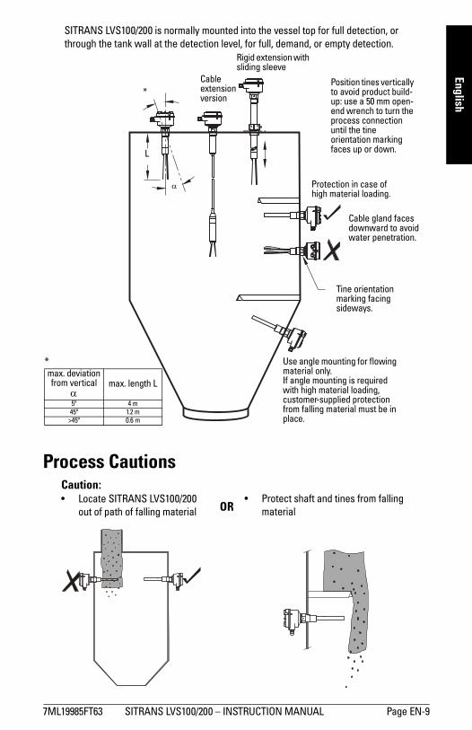
EnglishSITRANS LVS100/200 is normally mounted into the vessel top for full detection, or through the tank wall at the detection level, for full, demand, or empty detection.
Process Cautions
Cable gland faces downward to avoid water penetration.
Protection in case of high material loading.
Use angle mounting for flowing material only. If angle mounting is required with high material loading, customer-supplied protection from falling material must be in place.
*max. deviation from vertical
αmax. length L
5º 4 m45º 1.2 m
>45º 0.6 m
*
L
Tine orientation marking facing sideways.
α
Position tines vertically to avoid product build-up: use a 50 mm open-end wrench to turn the process connection until the tine orientation marking faces up or down.
Rigid extension with sliding sleeve
Cable extension version
Caution:� Locate SITRANS LVS100/200
out of path of falling material� Protect shaft and tines from falling
materialOR

Page EN-10 SITRANS LVS100/200 � INSTRUCTION MANUAL 7ML19985FT63
mm
mm
m
Engl
ish
Dimensions - SITRANS LVS100
120 mm (4.72")
150 mm (5.91")
customer supplied process flange
170 to 4000 mm (6.69 to 157"): customer-specified rigid
125 mm (4.92"): standard fork
60 mm (2.36")
60 mm (2.36") 75 mm
(2.95")
tine orientation marking
Zone 21(Cat. 2)
Zone 20(Cat. 1)
threaded bushing [max. temp. +80°C (+176°F)]
tine
7ML19985FT63 SITRANS LVS100/200 � INSTRUCTION MANUAL Page EN-11
mm
mm
m
English
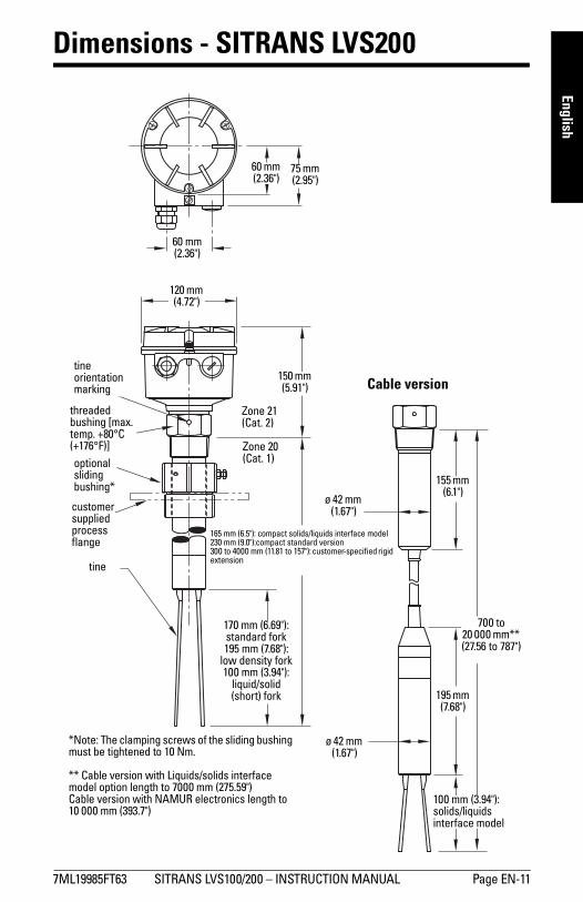
Dimensions - SITRANS LVS200
120 mm (4.72")
150 mm (5.91")
customer supplied process flange
165 mm (6.5"): compact solids/liquids interface model230 mm (9.0"):compact standard version300 to 4000 mm (11.81 to 157"): customer-specified rigid extension
170 mm (6.69"): standard fork195 mm (7.68"):
low density fork 100 mm (3.94"):
liquid/solid (short) fork
60 mm (2.36")
60 mm (2.36")
75 mm (2.95")
tine orientation marking
Zone 21(Cat. 2)
Zone 20(Cat. 1)
threaded bushing [max. temp. +80°C (+176°F)]optional sliding bushing*
*Note: The clamping screws of the sliding bushing must be tightened to 10 Nm.
** Cable version with Liquids/solids interface model option length to 7000 mm (275.59")Cable version with NAMUR electronics length to 10 000 mm (393.7")
tine
100 mm (3.94"): solids/liquids interface model
Cable version
195 mm (7.68")
700 to 20 000 mm** (27.56 to 787")
155 mm (6.1")
ø 42 mm (1.67")
ø 42 mm (1.67")

Page EN-12 SITRANS LVS100/200 � INSTRUCTION MANUAL 7ML19985FT63
mm
mm
m
Engl
ish
Wiring
Connection recommendations� Use a fuse for the signal output (max. 10 A).� Provide protection for relay contacts to protect the device against spikes if inductive
loads are connected.
Precautions� Before opening the lid, ensure there are no dust deposits around
SITRANS LVS100/200, and that the atmosphere around the instrument is settled.� Make sure the main voltage does not exceed the maximum voltage listed on the
product label.� Ensure that no more than 8 mm of each wire is stripped (to avoid danger of contact
with live parts).� Ensure the boots for protecting cable terminations are no longer than 8 mm (to avoid
danger of contact with live parts).
WARNINGS:• Open SITRANS LVS100/200 only when supply voltage is switched off.• All field wiring must have insulation suitable for at least 250 V AC. • A disconnect switch must be in close proximity to the equipment and
within easy reach of the operator.• Use appropriate conduit or cable glands in hazardous locations.
Unused cable conduit fittings must be locked with a closing element or plug.
• Observe all pertinent rules and regulations in the country of installation.
Notes:European requirements� When mounting SITRANS LVS100/200 in hazardous areas, make sure the customer
supplied cable glands and/or plugs are certified ATEX 100a flameproof. The certified temperature range must be at least -40 to +70 °C (-40 to +158 °F). The minimum ingress protection requirement of IP6x according to European Standard EN 60529 must be satisfied. Observe special conditions for safe use of the cable gland described in the gland�s approval documentation.
� The requirements of European Standard EN 50281-1-2 regarding dust deposits and temperature must be followed.

7ML19985FT63 SITRANS LVS100/200 � INSTRUCTION MANUAL Page EN-13
mm
mm
m
English
Universal voltage (DPDT relay)(LVS100)
Universal voltage (SPDT relay)(LVS200)
12345678
alarm output relays
FSH/FSL adjustment
sensitivity adjustmentB = factory setting, A = decreased
AC: terminal 1: Lterminal 2: N19 to 230 V AC, + 10 %, 50 to 60 Hz, 8 VA
DC: terminal 1: +terminal 2: -19 to 50 V DC, + 10 %, 2 W
AB
FSH
FSL
LED
alarm output relay
FSH/FSL adjustment
sensitivity adjustmentB = factory setting, A = decreased sensitivity
AC: terminal 1: Lterminal 2: N19 to 230 V AC, + 10 %, 50 to 60 Hz, 8 VA
DC: terminal 1: +terminal 2: -
19 to 55 V DC, + 10 %, 1.5 W
protective earth terminal
AB
FSH
FSL
LED

Page EN-14 SITRANS LVS100/200 � INSTRUCTION MANUAL 7ML19985FT63
mm
mm
m
Engl
ish
Universal voltage (DPDT relay) 3-wire PNP(LVS200) (LVS200)
2-wire NAMUR IEC 60947-5-6 8/16 mA or 4 to 20 mA(LVS200) (LVS200) (LVS200)
PE +L
-N
alarm output relaysPE + -
load
AC: terminal 1: Lterminal 2: N19 to 230 V AC, + 10 %, 50 to 60 Hz, 18 VA
DC: terminal 1: +terminal 2: -19 to 55 V DC, + 10 %, 2 W
DC: terminal 1: +terminal 2: -18 to 50 V DC, + 10 %, 1.5 W
PE +L
-N PE + - PE + -
AC: terminal 1: Lterminal 2: N19 to 230 V AC, + 10 %,
50 to 60 Hz, 1.5 VADC: terminal 1: +
terminal 2: -19 to 230 V DC, + 10 %, 1 W
ca. 7 to 9 V DC, intrinsically safe(IEC 60947-5-6)
DC: terminal 1: +terminal 2: -12.5 to 36 V DC, + 0 %
7ML19985FT63 SITRANS LVS100/200 � INSTRUCTION MANUAL Page EN-15
mm
mm
m
English
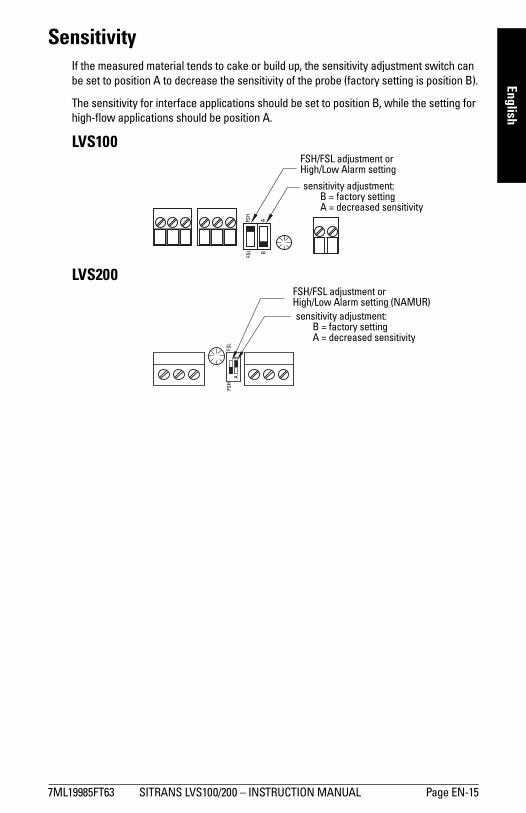
SensitivityIf the measured material tends to cake or build up, the sensitivity adjustment switch can be set to position A to decrease the sensitivity of the probe (factory setting is position B).
The sensitivity for interface applications should be set to position B, while the setting for high-flow applications should be position A.
LVS100
LVS200
FSH/FSL adjustment or High/Low Alarm setting
sensitivity adjustment:B = factory settingA = decreased sensitivity
FSH
FSL
AB
FSH/FSL adjustment or High/Low Alarm setting (NAMUR)sensitivity adjustment:
B = factory settingA = decreased sensitivity
FSH
FSL
AB
Page EN-16 SITRANS LVS100/200 � INSTRUCTION MANUAL 7ML19985FT63
mm
mm
m
Engl
ish
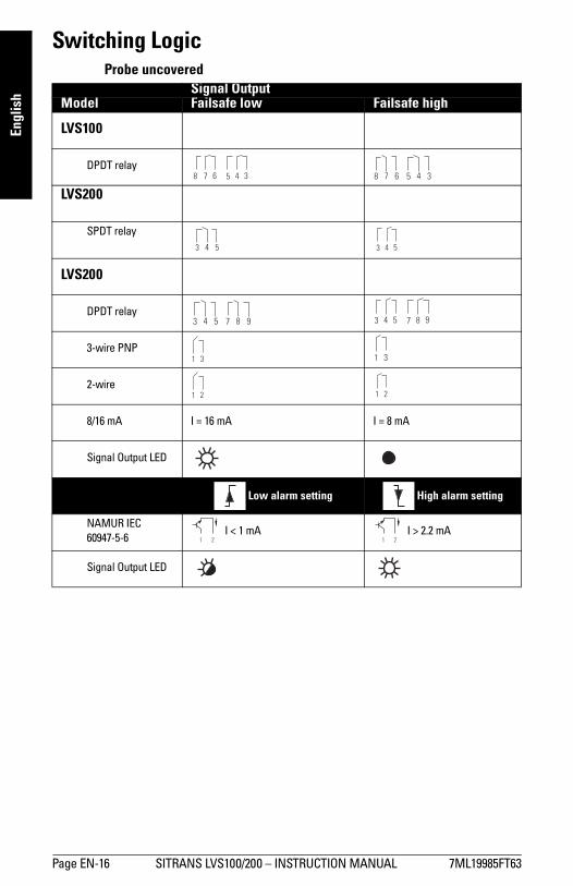
Switching LogicProbe uncovered
Signal OutputModel Failsafe low Failsafe high
LVS100
DPDT relay
LVS200
SPDT relay
LVS200
DPDT relay
3-wire PNP
2-wire
8/16 mA I = 16 mA I = 8 mA
Signal Output LED
Low alarm setting High alarm setting
NAMUR IEC 60947-5-6
I < 1 mA I > 2.2 mA
Signal Output LED
7 6 5 4 38 8 7 6 5 4 3
3 4 5 3 4 5

7ML19985FT63 SITRANS LVS100/200 � INSTRUCTION MANUAL Page EN-17
mm
mm
m
English
Probe covered
Signal OutputModel Failsafe low Failsafe high
LVS100
DPDT relay
LVS200
SPDT relay
LVS200
DPDT relay
3-wire PNP
2-wire
8/16 mA I = 8 mA I = 16 mA
Signal Output LED
Low alarm setting High alarm setting
NAMUR IEC 60947-5-6
I >2.2 mA I < 1 mA
Signal Output LED
8 7 6 5 4 3 7 6 5 4 38
3 4 5 3 4 5
Page EN-18 SITRANS LVS100/200 � INSTRUCTION MANUAL 7ML19985FT63
mm
mm
m
Engl
ish
Signal output and test options (LVS200)
Signal Output Delay
Universal voltage (DPDT) model
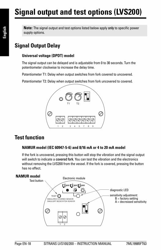
The signal output can be delayed and is adjustable from 0 to 30 seconds. Turn the potentiometer clockwise to increase the delay time.
Potentiometer T1: Delay when output switches from fork covered to uncovered.
Potentiometer T2: Delay when output switches from fork uncovered to covered.
Test function
NAMUR model (IEC 60947-5-6) and 8/16 mA or 4 to 20 mA model
If the fork is uncovered, pressing this button will stop the vibration and the signal output will switch to indicate a covered fork. You can test the vibration and the electronics without removing the LVS200 from the vessel. If the fork is covered, pressing the button has no effect.
Note: The signal output and test options listed below apply only to specific power supply options.
Test buttonElectronic module
diagnostic LED
NAMUR model
sensitivity adjustment:B = factory settingA = decreased sensitivity
AB
7ML19985FT63 SITRANS LVS100/200 � INSTRUCTION MANUAL Page EN-19
mm
mm
m
English
Vibration amplitude diagnosis
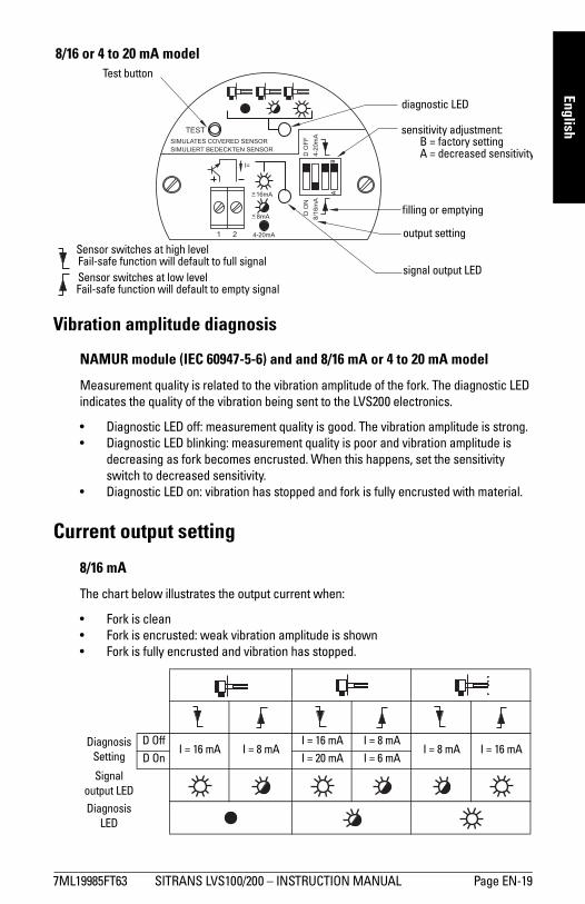
NAMUR module (IEC 60947-5-6) and and 8/16 mA or 4 to 20 mA model
Measurement quality is related to the vibration amplitude of the fork. The diagnostic LED indicates the quality of the vibration being sent to the LVS200 electronics.
� Diagnostic LED off: measurement quality is good. The vibration amplitude is strong.� Diagnostic LED blinking: measurement quality is poor and vibration amplitude is
decreasing as fork becomes encrusted. When this happens, set the sensitivity switch to decreased sensitivity.
� Diagnostic LED on: vibration has stopped and fork is fully encrusted with material.
Current output setting
8/16 mA
The chart below illustrates the output current when:
� Fork is clean� Fork is encrusted: weak vibration amplitude is shown� Fork is fully encrusted and vibration has stopped.
Diagnosis Setting
D OffI = 16 mA I = 8 mA
I = 16 mA I = 8 mAI = 8 mA I = 16 mA
D On I = 20 mA I = 6 mA
Signal output LED
Diagnosis LED
8/16 or 4 to 20 mA modelTest button
diagnostic LED
sensitivity adjustment:B = factory settingA = decreased sensitivity
BA
filling or emptying
output setting
signal output LED
Sensor switches at high levelFail-safe function will default to full signalSensor switches at low levelFail-safe function will default to empty signal

Page EN-20 SITRANS LVS100/200 � INSTRUCTION MANUAL 7ML19985FT63
mm
mm
m
Engl
ish
The output current can indicate weak vibration amplitude with the diagnosis setting D ON. If the diagnosis is set to D OFF, the output will be either 8 mA or 16 mA depending on high or low level settings.
If the diagnosis is set to D ON, the output will change from 16 to 20 mA and from 8 to 6 mA if the vibration is weak. This output can be passed to an external 4 to 20 mA output. There is an internal delay of 10 seconds before the change happens, so that the external output does not indicate a weak vibration when the vibration is stopped and started during normal measurement operation.
Buildup Detection (8/16 mA or 4 to 20 mA version)With the 4 to 20 mA setting, you can recognize material buildup on the fork using a PLC or data logger.
In this mode, the Diagnostic setting has no influence. The LED showing signal output is off.
20 mA: The fork is clean.
<20 mA and >12/12.5 mA: The vibration amplitude is decreased by the material buildup.
<12/12.5 mA and >7/8 mA: This range indicates a weak vibration. The internal LED showing diagnosis begins blinking to indicate a weak signal. If you are using a PLC to evaluate the echo, delay the response time to this indicator for approximately 10 seconds. A hysteresis of 0.5 mA (between 12 and 12.5 mA) is recommended.
7/8 mA: This point indicates that the fork is mostly encrusted.
6 mA: This point indicates that the fork is fully encrusted.
increasing material buildup
Amplitude is 100%
Amplitude is 0%
Amplitude is 100%
Amplitude is 0%
With standard sensitivity setting With decreased sensitivity setting
6 mA
7/8 mA
12/12.5 mA
20 mA
outp
ut c
urre
nt standard sensitivity
decreased sensitivity
Vibration damping by material
7ML19985FT63 SITRANS LVS100/200 � INSTRUCTION MANUAL Page EN-21
mm
mm
m
English
Maintenance
SITRANS LVS100/200 require no maintenance or cleaning under normal operating conditions. Under severe operating conditions, the tines may require periodic cleaning. Brush off any accumulated deposits, taking care not to bend the tines.
Unit Repair and Excluded LiabilityAll changes and repairs must be done by qualified personnel, and applicable safety regulations must be followed. Please note the following:
� The user is responsible for all changes and repairs made to the device.� All new components must be provided by Siemens Milltronics Process Instruments Inc.� Restrict repair to faulty components only.� Do not re-use faulty components.

Page EN-22 SITRANS LVS100/200 � INSTRUCTION MANUAL 7ML19985FT63
mm
mm
m
Engl
ish
SITRANS LVS200 Pipe Extended Version
AssemblySuggested tools:
1. Open the enclosure lid; remove electronics module.2. Lead the sensor cable through the customer supplied 1" tube and enclosure.3. Assemble the fork assembly, the pipe extension, and the enclosure using the 36 mm
open end wrench. Seal the pipe threads with an appropriate sealant.
4. Line up the fork and the tine orientation marking as shown in dimension drawing on page 12. (The tine orientation marking on the process connection is to identify the vertical orientation of the fork.)
5. Shorten sensor cable to a free length of 150 mm (5.9"). 6. Shorten earth cable to a free length of 220 mm (8.7"). 7. Prepare sensor cable as shown above, stripping a maximum of 8 mm from each
wire.
� medium Phillips or 6 to 8 mm (¼�) flat screwdriver � terminal crimper
� 3 mm (1/8�) flat screwdriver � 36 mm open end wrench
� wire cutters � pipe wrench
� wire strippers
Note: Do not turn fork assembly. Do not bend the fork during assembly.
enclosure customer supplied pipe extension
fork assembly
earth cable (green/yellow)220 mm
(8.7")
150 mm (5.9")
8 mm max.18 mm

7ML19985FT63 SITRANS LVS100/200 � INSTRUCTION MANUAL Page EN-23
mm
mm
m
English
8. Connect the sensor cable to the terminal connection board shown above.9. Secure the sensor cable with cable ties.10. Crimp the ring terminal 4 mm (0.19") to sensor earth cable.
11. Connect electronics module and terminal connection board. Be sure that all terminals are tight.
12. Insert the electronics module into the housing. The terminal connection board is used to guide the cable into the extension tube.
13. Fold cable as shown in diagram above. 14. Secure the electronics module as shown in diagram below.
electronics module, flat side up
4 = BLACK (T) 3 = SHIELD (M) 2 = RED (R-) 1 = WHITE (R+)
3 mm (1/8�) screw driver
cable ties
Connect protection earth of the enclosure to terminal of the electronics module.
Connect earth cable of the fork to the electronics earth terminal.

Page EN-24 SITRANS LVS100/200 � INSTRUCTION MANUAL 7ML19985FT63
mm
mm
m
Engl
ish
Assembly Overview Drawing
½” NPT
M20x1.5
1 ½” NPT
1 ½" BSPT
1" NPT
G 1"
lid
electronics module
terminal connectionboard
sensor cable
enclosureassembly
process connection
tine orientation marking
process thread 1 ½� NPT (taper) orR 1 ½� (BSPT)
thread G1� or 1" NPT(use appropriate
thread sealant)
fork
fork assembly
thread G1� or 1" NPT(use appropriate
thread sealant)
1" schedule 40 pipe(internal min.
dia. 25.4 mm (customersupplied and mounted)
X = L - 255 mm (10")
min. 18 mm (0.75")
min. 18 mm (0.75")
SW 36
Note: Threaded engagement to be a min. of 7 mm (0.27")
approx. 138 mm
(5.4")
L = 300 to 3800 mm (11.8 to 149.6")
170 mm(6.7")
process thread
cable entries
1" pipe thread
7ML19985FT63 SITRANS LVS100/200 � BETRIEBSANLEITUNG Seite DE-1
mm
mm
m
Deutsch
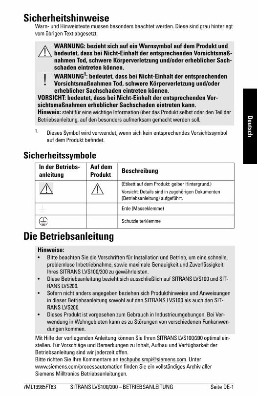
SicherheitshinweiseWarn- und Hinweistexte müssen besonders beachtet werden. Diese sind grau hinterlegt vom übrigen Text abgesetzt.
Sicherheitssymbole
Die Betriebsanleitung
Mit Hilfe der vorliegenden Anleitung können Sie Ihren SITRANS LVS100/200 optimal ein-stellen. Für Vorschläge und Bemerkungen zu Inhalt, Aufbau und Verfügbarkeit der Betriebsanleitung sind wir jederzeit offen.Bitte richten Sie Ihre Kommentare an [email protected]. Unter www.siemens.com/processautomation finden Sie ein vollständiges Archiv aller Siemens Milltronics Betriebsanleitungen.
WARNUNG: bezieht sich auf ein Warnsymbol auf dem Produkt und bedeutet, dass bei Nicht-Einhalt der entsprechenden Vorsichtsmaß-nahmen Tod, schwere Körperverletzung und/oder erheblicher Sach-schaden eintreten können.WARNUNG1: bedeutet, dass bei Nicht-Einhalt der entsprechenden Vorsichtsmaßnahmen Tod, schwere Körperverletzung und/oder erheblicher Sachschaden eintreten können.
VORSICHT: bedeutet, dass bei Nicht-Einhalt der entsprechenden Vor-sichtsmaßnahmen erheblicher Sachschaden eintreten kann.Hinweis: steht für eine wichtige Information über das Produkt selbst oder den Teil der Betriebsanleitung, auf den besonders aufmerksam gemacht werden soll.
1. Dieses Symbol wird verwendet, wenn sich kein entsprechendes Vorsichtssymbol auf dem Produkt befindet.
In der Betriebs-anleitung
Auf dem Produkt Beschreibung
(Etikett auf dem Produkt: gelber Hintergrund.)
Vorsicht: Details sind in zugehörigen Dokumenten (Betriebsanleitung) aufgeführt.
Erde (Masseklemme)
Schutzleiterklemme
Hinweise:� Bitte beachten Sie die Vorschriften für Installation und Betrieb, um eine schnelle,
problemlose Inbetriebnahme, sowie maximale Genauigkeit und Zuverlässigkeit Ihres SITRANS LVS100/200 zu gewährleisten.
� Diese Betriebsanleitung bezieht sich ausschließlich auf SITRANS LVS100 und SIT-RANS LVS200.
� Sofern nicht anders angegeben beziehen sich Produkthinweise und Anweisungen in dieser Betriebsanleitung sowohl auf den SITRANS LVS100 als auch den SIT-RANS LVS200.
� Dieses Produkt ist vorgesehen zum Gebrauch in Industrieumgebungen. Bei Ver-wendung in Wohngebieten kann es zu Störungen von verschiedenen Funkanwen-dungen kommen.

Seite DE-2 SITRANS LVS100/200� BETRIEBSANLEITUNG 7ML19985FT63
mm
mm
m
Deut
sch
SITRANS LVS100 und LVS200 Einführung
SITRANS LVS100 und SITRANS LVS200 sind in einer Standardausführung verfügbar. Der SITRANS LVS200 bietet noch zwei zusätzliche Ausführungen.
SITRANS LVS100, SITRANS LVS200 - Standardausführung� Der SITRANS LVS100/200, Standardausführung, ist ein Vibrations-Grenzstandschal-
ter, der die An- oder Abwesenheit rieselfähiger Schüttgüter in Behältern, Silos oder Trichtern erfasst. Er hat ein kompaktes Design, das einen senkrechten oder waag-rechten Einbau erlaubt. Die vibrierende Schwinggabel bewirkt eine gewisse Selbst-reinigung des Gerätes vom Messstoff.� SITRANS LVS100 ist eine einfache Schwinggabelsonde mit einer Schüttdichte
ab 60 g/l (3.8 lb/ft3). Der LVS100 ist mit Stabverlängerungsoptionen bis 4 000 mm (157") verfügbar.
� Der SITRANS LVS200 bietet mehrere Ausgangsoptionen zur Meldung des Grenzstandes bei Produkten wie Kalk, Styropor, Mehl und Kunststoffgranulat, ab 20 g/l (1.2 lb/ft3). Er ist in einem breiteren Anwendungsspektrum einsetzbar und kann Schüttdichten von weniger als 5 g/l messen. Darüberhinaus bietet der LVS200 eine größere Auswahl an Prozesskonfigurationen. Die Standard-Schwinggabelsonde des LVS200 ist mit verschiedenen Seilverlängerungen bis maximal 20 000 mm (787") verfügbar (Seilverlängerungen sind nur für einen Einbau von oben geeignet). Für eine erhöhte Empfindlichkeit steht optional eine längere Schwinggabelsonde zur Verfügung.
SITRANS LVS200 - Ausf. Trennschichtmessung Flüssig/Fest� Die Ausführung Trennschichtmessung Flüssigkeiten/Schüttgüter des SITRANS
LVS200 ist ein Vibrations-Grenzstandschalter, der auch abgesetzte Feststoffe in Flüs-sigkeiten oder Feststoffe in beengten Anlagen, wie z. B. Speiserohren, erfassen kann. Diese Ausführung ist so konzipiert, dass Flüssigkeiten ignoriert werden, um die Trenn-schicht zwischen einem Feststoff und einer Flüssigkeit zu erfassen. Die mit diesem Design verbundene kurze Schwinggabelsonde ist auch mit verschiedenen Seilverlän-gerungen bis maximal 20 000 mm (787"), nur für den Einbau von oben verfügbar.
SITRANS LVS200 - Ausführung mit Rohrverlängerung� Die Ausführung Rohrverlängerung des SITRANS LVS200 ist ein Vibrations-Grenz-
standschalter, bei dem ein kundenseitiges Verlängerungsrohr [max. Länge 3800 mm (150")] mit der Standard- oder Flüssigkeit/Feststoff-Ausführung (kurz) von LVS200 Schwinggabel und Elektronik verbunden wird. Dadurch kann die Elektronik für Appli-kationen, die eine Stabverlängerung erfordern, von der Schwinggabel abgesetzt werden. Angaben zum Aufbau finden Sie unter SITRANS LVS200 Ausführung mit Rohrverlängerung auf Seite 22.
Hinweise:� Installation, Wartung und Inbetriebnahme müssen durch qualifiziertes, technisches
Personal vorgenommen werden.� Der SITRANS LVS100/200 darf nur gemäß den Anweisungen in dieser Betriebsan-
leitung verwendet werden.

7ML19985FT63 SITRANS LVS100/200 � BETRIEBSANLEITUNG Seite DE-3
mm
mm
m
Deutsch
Wesentliche Merkmale� Hohe mechanische Beständigkeit� Starke Schwingung, auch für hohe Belastungen geeignet� Verdrehbares Gehäuse� LVS100: R 1½" (BSPT); 1¼" NPT (kegelig) Gewindeanschluss� LVS200: 1½� NPT oder R 1½� (BSPT) Edelstahl-Gewindeanschluss, oder R 2" (BSPT)
oder NPT Schiebemuffe. DN 100 und 2, 3, 4" ASME Flanschoptionen verfügbar. � Für Material mit hoher oder niedriger Schüttdichte geeignet
LVS100 Standardausführung: 60 g/l (3.8 lb/ft3)min.LVS200 Standardausführung: 20 g/l (1.2 lb/ft3)min.LVS200 Standardausführung mit Schwinggabel niedriges Schüttgewicht: 5 g/l (0.3 lb/ft3) min.LVS200 Ausführung Trennschichtmessung fest/flüssig: 50 g/l (3.0 lb/ft3) min.
Anwendungsbereiche� Trockenkalk, Styropor, Mehl, Kunststoffgranulat� Trockenes Schüttgut mit hoher oder geringer Schüttdichte� Trennschichterfassung von Feststoffen in einer Flüssigkeit (Filterbett)� Flüssigkeit/Feststoff-Ausführung des LVS200 unterscheidet die Zustände
Durchfluss/kein Durchfluss in Rohren
ArbeitsprinzipEin Signal vom elektrischen Schaltkreis bewirkt eine piezoelektrische Anregung der Sonde, die zum Schwingen gebracht wird. Wird die Sonde durch das Füllgut bedeckt, so wird die dadurch entstehende Dämpfung elektronisch registriert und ein entsprechender Schaltausgang nach einer Sekunde Ansprechverzögerung betätigt. Sobald die Schwings-onde frei vom Materialdruck ist, nimmt die Schwingung wieder auf und das Relais kehrt in seinen normalen Zustand zurück.
WARNUNGEN:
• Dieses Produkt wird als druckhaltendes Ausrüstungsteil im Sinne der Richtlinie 97 / 23 / EG bezeichnet und ist nicht für den Einsatz als Sicher-heitsvorrichtung bestimmt.
• Die Werkstoffe werden entsprechend ihrer chemischen Beständigkeit (oder Trägheit) für allgemeine Zwecke gewählt. Bei Einsatz in beson-deren Umgebungen prüfen Sie vor Installation die chemische Bestän-digkeit anhand einschlägiger Tabellen.

Seite DE-4 SITRANS LVS100/200� BETRIEBSANLEITUNG 7ML19985FT63
mm
mm
m
Deut
sch
Technische Daten
VersorgungsspannungLVS100
� AC 19 ... 230 V, +10 %, 50 ... 60 Hz, 8 VA / DC 19 ... 50 V, +10 %, 2 W
LVS200
� AC 19 ... 230 V, +10 %, 50 ... 60 Hz, 8 VA / DC 19 ... 55 V, +10 %, 1,5 W� DC 18 ... 50 V Dreileiter PNP� DC 7 ... 9 V (NAMUR Trennverstärker erforderlich) NAMUR IEC 60947-506,
Zweileiter� 8/16 mA oder 4 ... 20 mA; DC 12,5 ... 35 V, Zweileiter
FunktionMessfrequenz
LVS100
� Standard ca. 200 HzLVS200
� Standard ca. 125 Hz� Ausführung Trennschichtmessung ca. 350 Hz� Option erhöhte Empfindlichkeit ca. 90 Hz
Signalverzögerung
� Sonde frei / bedeckt ca. 1 Sekunde� Sonde bedeckt / frei ca. 1 bis 2 Sekunden
Relais Ansprechverzögerung (DPDT Ausführung) (LVS200)
� Einstellbar bis 30 Sekunden
Empfindlichkeit
� Max. oder Min., über Schalter wählbar
Min. Schüttgewicht
LVS100
� Standardausführung ca. 60 g/l (3.8 lb/ft3)LVS200
� Standardausführung ca. 20 g/l (1.2 lb/ft³)� Standardausführung mit Schwing-
gabel niedriges Schüttgewicht 5 g/l (0.3 lb/ft³)� Ausführung Trennschichtmessung ca. 50 g/l (3 lb/ft³)
Hinweis: Siemens Milltronics ist bestrebt, die Genauigkeit der technischen Daten zu gewährleisten, behält sich jedoch jederzeit das Recht auf Änderung vor.

7ML19985FT63 SITRANS LVS100/200 � BETRIEBSANLEITUNG Seite DE-5
mm
mm
m
DeutschMaximale Korngröße
� LVS100 8 mm (0.32")� LVS200 10 mm (0.39")
AlarmausgangLVS100
� Ausführung mit 2 Relais DPDT RelaisRelais Failsafe: Max oder Min,
über Schalter wählbarRelais 8 A bei AC 250 V,
ohmsche Last / Relais 5 A bei DC 30 V,ohmsche Last
LVS200
� Ausführung mit 1 Relais SPDT RelaisRelais Failsafe: Max oder Min,
über Schalter wählbarRelais 8 A bei AC 250 V,
ohmsche Last / Relais 5 A bei DC 30 V, ohmsche Last
� Ausführung mit 2 Relais DPDT RelaisRelais Failsafe: Max oder Min,
über Schalter wählbarRelais 8 A bei AC 250 V,
ohmsche Last / Relais 5 A bei DC 30 V,ohmsche Last
� Dreileiter PNP Open Collector: Max. 0,4 A Dauerlast, kurzschluss- und überlastfest; Schaltspannung: max. 50 V (Verpolungsschutz)
� mA Ausgang (Erfassung von Ablagerungen) 8/16 mA oder 4 ... 20 mA;
Auflösung 4 ... 20 mA, ±0,1 mA

Seite DE-6 SITRANS LVS100/200� BETRIEBSANLEITUNG 7ML19985FT63
mm
mm
m
Deut
sch
MechanikProzessanschluss
LVS100
� Gewinde R 1½" (BSPT); 1¼" NPT (kegelig) ANSI B 1.20.1
� Gewindewerkstoff Edelstahl W.-Nr. 1.4581 (316 Ti) oder 1.4301 (304) für spezifische Konfigurationen
LVS200
� Gewinde 1½� NPT (kegelig), R 1½� (BSPT)� Gewindewerkstoff Edelstahl W.-Nr. 1.4301 (304) oder
optional Edelstahl W.-Nr. 1.4571 (316 Ti)� Flansche DN 100 PN6, DN 100 PN16,
2", 3", 4" ASME 150 lb Flansche� optionale Schiebemuffe mit R 2" (BSPT) oder NPT (kegelig)
Gewinde
Schwinger
� Werkstoff der Schwinger Edelstahl W.-Nr. 1.4571 (316Ti)
(Schwinger mit PTFE1 Beschichtung auf Anfrage erhältlich. Bestellinformationen erhalten Sie von Ihrer örtlichen Siemens Geschäftsstelle.)
Gehäuse
� Bauweise Aluminium, epoxidbeschichtet� Kabeleinführung 2 x M20x1,5 oder 2 x ½" NPT� Schutzart IP66/Type 4X/NEMA 4X
Gewicht
� Standardausf., ohne Verlängerung 2,0 kg (4.4 lb)� Feststoff/Flüssigkeit, ohne Verlängerung 1,9 kg (4.2 lb)
Umgebungsbedingungen� Montage innen / im Freien� Höhe max. 2000 m (6562 ft)� Umgebungstemperatur �40 ... +60 °C (�40 ... +140 °F)� relative Feuchtigkeit 0 ... 100% (für Montage im Freien geeignet;
Schutzart: IP66/Type 4X/NEMA 4X)� Installationskategorie III� Verschmutzungsgrad 2
1. Polytetrafluorethylen

7ML19985FT63 SITRANS LVS100/200 � BETRIEBSANLEITUNG Seite DE-7
mm
mm
m
Deutsch
ProzessdatenTemperatur
� Für alle Zulassungen mit Ausnahme von CSA Class II, Gruppe G: �40 ... +150 °C (�40 ... +302 °F)
� CSA Class II, Gruppe G: �40 ... +140 °C (�40 ... +284 °F), CSA Temperaturcode T3B
� Für Applikationen, in denen die Prozesstemperatur +80 °C (+176 °F) übersteigt, darf die maximale Oberflächentemperatur am Gewindeeinsatz maximal +80 °C (+176 °F) betragen.
� Max. Oberflächentemperatur des Gehäuses (Kategorie 2D): +90 °C (+194 °F) (ATEX-relevant)
� Max. Oberflächentemperatur an der Verlängerung (Kategorie 1D): +150 °C (+302 °F) (ATEX-relevant)
Druck
� max. 10 bar, Manometer (145 psi, Manometer)
ZulassungenLVS100
� CE� ATEX II 1/2D� CSA/FM Class II, III, Div. 1, Gruppen E, F, G� C-TICK
LVS200
� CSA/FM Allgemeine Verwendung� CE� CSA/FM Staub-Ex-Sicherheit� ATEX II 1/2D� CSA/FM IS Class I, II, III Div. 1, Gruppen A ... G, FM Class I, Aex ia IIC, CSA Class 1,
Ex ia IIC, nur verfügbar mit DC 7 ... 9 V Hilfsenergie mit NAMUR Trennverstärker� ATEX II 1G und 1/2G Eex ia IIC; ATEX II 1D und 1/2D, nur verfügbar mit DC 7 ... 9 V
Hilfsenergie mit NAMUR Trennverstärker� C-TICK
Hinweis: Angaben zum Druck in explosionsgefährdeten BereichenDie Bauart des Gerätes erlaubt einen Überdruck von max. 10 bar. Dieser Druck ist für Testzwecke zugelassen. Die ATEX Zulassung bezieht sich auf Überdruckwerte zwi-schen -0,2 und 0,1 bar in explosionsgefährdeten Bereichen. Für höhere oder niedrigere Druckwerte ist die Zulassung ungültig.
Seite DE-8 SITRANS LVS100/200� BETRIEBSANLEITUNG 7ML19985FT63
mm
mm
m
Deut
sch
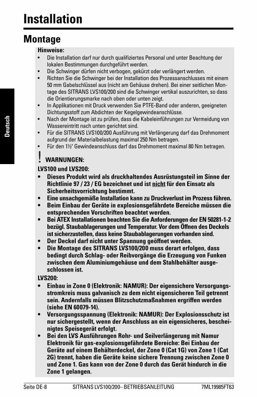
InstallationMontage
Hinweise:� Die Installation darf nur durch qualifiziertes Personal und unter Beachtung der
lokalen Bestimmungen durchgeführt werden.� Die Schwinger dürfen nicht verbogen, gekürzt oder verlängert werden.� Richten Sie die Schwinger bei der Installation des Prozessanschlusses mit einem
50 mm Gabelschlüssel aus (nicht am Gehäuse drehen). Bei einer seitlichen Mon-tage des SITRANS LVS100/200 sind die Schwinger vertikal auszurichten, so dass die Orientierungsmarke nach oben oder unten zeigt.
� In Applikationen mit Druck verwenden Sie PTFE-Band oder anderen, geeigneten Dichtungsstoff zum Abdichten der Kegelgewindeanschlüsse.
� Nach der Montage ist zu prüfen, dass die Kabeleinführungen zur Vermeidung von Wassereintritt nach unten gerichtet sind.
� Für die SITRANS LVS100/200 Ausführung mit Verlängerung darf das Drehmoment aufgrund der Materialbelastung maximal 250 Nm betragen.
� Für den 1½" Gewindeanschluss darf das Drehmoment maximal 80 Nm betragen.
WARNUNGEN: LVS100 und LVS200:• Dieses Produkt wird als druckhaltendes Ausrüstungsteil im Sinne der
Richtlinie 97 / 23 / EG bezeichnet und ist nicht für den Einsatz als Sicherheitsvorrichtung bestimmt.
• Eine unsachgemäße Installation kann zu Druckverlust im Prozess führen.• Beim Einbau der Geräte in explosionsgefährdete Bereiche müssen die
entsprechenden Vorschriften beachtet werden.• Bei ATEX Installationen beachten Sie die Anforderungen der EN 50281-1-2
bezügl. Staubablagerungen und Temperatur. Vor dem Öffnen des Deckels ist sicherzustellen, dass keine Staubablagerungen vorhanden sind.
• Der Deckel darf nicht unter Spannung geöffnet werden.• Die Montage des SITRANS LVS100/200 muss derart erfolgen, dass
bedingt durch Schlag- oder Reibvorgänge die Erzeugung von Funken zwischen dem Aluminiumgehäuse und dem Stahlbehälter ausge-schlossen ist.
LVS200:• Einbau in Zone 0 (Elektronik: NAMUR): Der eigensichere Versorgungs-
stromkreis muss galvanisch zu dem nicht eigensicheren Teil getrennt sein. Andernfalls müssen Blitzschutzmaßnahmen ergriffen werden (siehe EN 60079-14).
• Versorgungsspannung (Elektronik: NAMUR): Der Explosionsschutz ist nur sichergestellt, wenn der Anschluss an ein eigensicheres, beschei-nigtes Speisegerät erfolgt.
• Bei den LVS Ausführungen Rohr- und Seilverlängerung mit Namur Elektronik für gas-explosionsgefährdete Bereiche: Bei Einbau der Geräte auf einem Behälterdeckel, der Zone 0 (Cat 1G) von Zone 1 (Cat 2G) trennt, haben die Geräte keine sichere Trennung zwischen Zone 0 und Zone 1. Gas kann von der Zone 0 durch das Gerät hindurch in die Zone 1 gelangen.

7ML19985FT63 SITRANS LVS100/200 � BETRIEBSANLEITUNG Seite DE-9
mm
mm
m
DeutschDer SITRANS LVS100/200 wird üblicherweise von oben als Vollmelder oder seitlich in Höhe des zu erfassenden Füllstandes als Voll-, Leer- oder Bedarfsmelder in den Behälter eingeschraubt.
Prozessbedingungen
Kabelverschraubung zeigt nach unten zur Vermeidung von Wassereintritt.
Stahlwinkel bei hoher Materialbelastung.
Ein schräger Einbau empfiehlt sich nur bei rieselfähigem Material. Bei starker Materialbelastung wird in diesem Fall ein kundenseitiger Stahlwinkel zum Schutz vor herab-fallendem Material empfohlen.
*max. Abweichung von der Vertikalen
αmax. Länge
L
5º 4 m45º 1,2 m
>45º 0,6 m
*
L
Orientierungs-marke ist seitlich ausgerichtet.
α
Schwinger vertikal ausrich-ten, um Materialablagerun-gen zu vemeiden: Gabelschlüssel 50 mm ver-wenden, um den Prozess-anschluss zu drehen, bis die Orientierungsmarke nach oben oder unten zeigt.
Rohrverlängerung mit Schiebemuffe
Ausführung Seilverlän-gerung
Vorsicht:� Den SITRANS LVS100/200 nicht
unterhalb der Befüllung anbringen� Schützen Sie die Welle und die Schwin-
ger vor herabfallendem MaterialODER

Seite DE-10 SITRANS LVS100/200� BETRIEBSANLEITUNG 7ML19985FT63
mm
mm
m
Deut
sch
Abmessungen - SITRANS LVS100
120 mm (4.72")
150 mm (5.91")
kunden-seitiger Prozess-flansch
170 ... 4000 mm (6.69 ... 157"): Rohrverlängerung nach Kundenmaß
125 mm (4.92"): Standard Schwinggabel
60 mm (2.36")
60 mm (2.36") 75 mm
(2.95")
Orientierungs-markierung
Zone 21(Kat. 2)
Zone 20(Kat. 1)
Gewinde-buchse [max. Temp. +80°C (+176°F)]
Schwinger
7ML19985FT63 SITRANS LVS100/200 � BETRIEBSANLEITUNG Seite DE-11
mm
mm
m
Deutsch
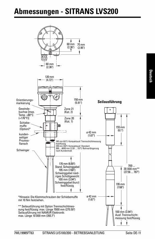
Abmessungen - SITRANS LVS200
120 mm (4.72")
150 mm (5.91")
kunden-seitiger Prozess-flansch
165 mm (6.5"): Kompaktausf. Trennschichtmessung fest/flüssig230 mm (9,0"): Kompaktausf. Standard300 ... 4000 mm (11.81 ... 157"): Rohrverlängerung nach Kundenmaß
170 mm (6.69"): Stand. Schwinggabel
195 mm (7.68"):Schwinggabel nied-riges Schüttgewicht
100 mm (3.94"): Schwinggabel (kurz)
fest/flüssig
60 mm (2.36")
60 mm (2.36")
75 mm (2.95")
Orientierungs-markierung
Zone 21(Kat. 2)
Zone 20(Kat. 1)
Gewinde-buchse [max. Temp. +80°C (+176°F)]Schiebe-muffe (Option)*
*Hinweis: Die Klemmschrauben der Schiebemuffe mit 10 Nm festziehen.
** Seilausführung mit Option Trennschichtmes-sung fest/flüssig: max. Länge 7000 mm (275.59")Seilausführung mit NAMUR Elektronik: max. Länge 10 000 mm (393.7")
Schwinger
100 mm (3.94"): Ausf. Trennschicht-messung fest/flüssig
Seilausführung
195 mm (7.68")
700 ... 20 000 mm** (27.56 ... 787")
155 mm (6.1")
ø 42 mm (1.67")
ø 42 mm (1.67")
Seite DE-12 SITRANS LVS100/200� BETRIEBSANLEITUNG 7ML19985FT63
mm
mm
m
Deut
sch
Anschluss
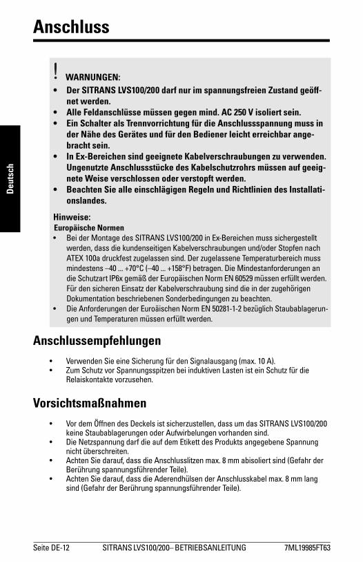
Anschlussempfehlungen� Verwenden Sie eine Sicherung für den Signalausgang (max. 10 A).� Zum Schutz vor Spannungsspitzen bei induktiven Lasten ist ein Schutz für die
Relaiskontakte vorzusehen.
Vorsichtsmaßnahmen� Vor dem Öffnen des Deckels ist sicherzustellen, dass um das SITRANS LVS100/200
keine Staubablagerungen oder Aufwirbelungen vorhanden sind.� Die Netzspannung darf die auf dem Etikett des Produkts angegebene Spannung
nicht überschreiten.� Achten Sie darauf, dass die Anschlusslitzen max. 8 mm abisoliert sind (Gefahr der
Berührung spannungsführender Teile).� Achten Sie darauf, dass die Aderendhülsen der Anschlusskabel max. 8 mm lang
sind (Gefahr der Berührung spannungsführender Teile).
WARNUNGEN:• Der SITRANS LVS100/200 darf nur im spannungsfreien Zustand geöff-
net werden.• Alle Feldanschlüsse müssen gegen mind. AC 250 V isoliert sein. • Ein Schalter als Trennvorrichtung für die Anschlussspannung muss in
der Nähe des Gerätes und für den Bediener leicht erreichbar ange-bracht sein.
• In Ex-Bereichen sind geeignete Kabelverschraubungen zu verwenden. Ungenutzte Anschlussstücke des Kabelschutzrohrs müssen auf geeig-nete Weise verschlossen oder verstopft werden.
• Beachten Sie alle einschlägigen Regeln und Richtlinien des Installati-onslandes.
Hinweise:Europäische Normen� Bei der Montage des SITRANS LVS100/200 in Ex-Bereichen muss sichergestellt
werden, dass die kundenseitigen Kabelverschraubungen und/oder Stopfen nach ATEX 100a druckfest zugelassen sind. Der zugelassene Temperaturbereich muss mindestens �40 ... +70°C (�40 ... +158°F) betragen. Die Mindestanforderungen an die Schutzart IP6x gemäß der Europäischen Norm EN 60529 müssen erfüllt werden. Für den sicheren Einsatz der Kabelverschraubung sind die in der zugehörigen Dokumentation beschriebenen Sonderbedingungen zu beachten.
� Die Anforderungen der Euroäischen Norm EN 50281-1-2 bezüglich Staubablagerun-gen und Temperaturen müssen erfüllt werden.

7ML19985FT63 SITRANS LVS100/200 � BETRIEBSANLEITUNG Seite DE-13
mm
mm
m
Deutsch
Allspannung (DPDT Relais)(LVS100)
Allspannung (SPDT Relais)(LVS200)
12345678
Alarmausgangs-relais
Einstellschalter FSH/FSLEinstellg. Empfindlichkeit
B = Werkseinstellung, A = verminderte
Empfindlichkeit
AC: Klemme 1: LKlemme 2: NAC 19 ... 230 V, + 10 %, 50 ... 60 Hz, 8 VA
DC: Klemme 1: +Klemme 2: -DC 19 ... 50 V, + 10 %, 2 W
AB
FSH
FSL
LED
Alarmausgangsrelais
Einstellschalter FSH/FSL
Einstellung der EmpfindlichkeitB = Werkseinstellung, A = verminderte Empfindlichkeit
AC: Klemme 1: LKlemme 2: NAC 19 ... 230 V, + 10 %, 50 ... 60 Hz, 8 VA
DC: Klemme 1: +Klemme 2: -
DC 19 ... 55 V, + 10 %, 1,5 W
Schutzleiterklemme
AB
FSH
FSL
LED
Seite DE-14 SITRANS LVS100/200� BETRIEBSANLEITUNG 7ML19985FT63
mm
mm
m
Deut
sch
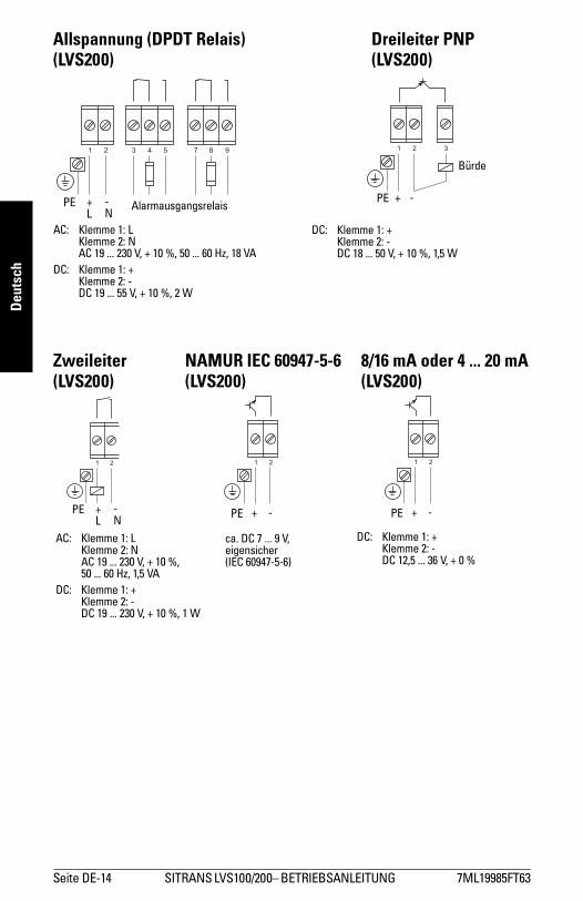
Allspannung (DPDT Relais) Dreileiter PNP(LVS200) (LVS200)
Zweileiter NAMUR IEC 60947-5-6 8/16 mA oder 4 ... 20 mA(LVS200) (LVS200) (LVS200)
PE +L
-N
AlarmausgangsrelaisPE + -
Bürde
AC: Klemme 1: LKlemme 2: NAC 19 ... 230 V, + 10 %, 50 ... 60 Hz, 18 VA
DC: Klemme 1: +Klemme 2: -DC 19 ... 55 V, + 10 %, 2 W
DC: Klemme 1: +Klemme 2: -DC 18 ... 50 V, + 10 %, 1,5 W
PE +L
-N PE + - PE + -
AC: Klemme 1: LKlemme 2: NAC 19 ... 230 V, + 10 %, 50 ... 60 Hz, 1,5 VA
DC: Klemme 1: +Klemme 2: -DC 19 ... 230 V, + 10 %, 1 W
ca. DC 7 ... 9 V, eigensicher(IEC 60947-5-6)
DC: Klemme 1: +Klemme 2: -DC 12,5 ... 36 V, + 0 %

7ML19985FT63 SITRANS LVS100/200 � BETRIEBSANLEITUNG Seite DE-15
mm
mm
m
Deutsch
EmpfindlichkeitWenn das zu messende Material zur Ansatzbildung neigt, besteht die Möglichkeit, den Einstellschalter auf Stellung "A" umzulegen, um die Sonde unempfindlicher zu machen (Werkseinstellung = B).
In Applikationen zur Trennschichtmessung ist die Empfindlichkeit auf B zu stellen, während zur Messung hoher Materialvolumen die Stellung A gewählt werden sollte.
LVS100
LVS200
Einstellschalter FSH/FSL oder Max/Min. Alarm Einstellung
Einstellung der Empfindlichkeit:B = WerkseinstellungA = verminderte Empfindlichkeit
FSH
FSL
AB
Einstellschalter FSH/FSL oder Max/Min. Alarm Einstellung (NAMUR)Einstellung der Empfindlichkeit:
B = WerkseinstellungA = verminderte Empfindlichkeit
FSH
FSL
AB

Seite DE-16 SITRANS LVS100/200� BETRIEBSANLEITUNG 7ML19985FT63
mm
mm
m
Deut
sch
SchaltlogikSonde nicht bedeckt
SignalausgangAusführung FSL (Failsafe Min) FSH (Failsafe Max)
LVS100
Relais DPDT
LVS200
Relais SPDT
LVS200
Relais DPDT
Dreileiter PNP
Zweileiter
8/16 mA I = 16 mA I = 8 mA
LED Signalaus-gang
Min. Alarm Einstellung Max. Alarm Einstellung
NAMUR IEC 60947-5-6
I < 1 mA I > 2,2 mA
LED Signalaus-gang
7 6 5 4 38 8 7 6 5 4 3
3 4 5 3 4 5
3 4 5 7 8 9 3 4 5 7 8 9
7ML19985FT63 SITRANS LVS100/200 � BETRIEBSANLEITUNG Seite DE-17
mm
mm
m
Deutsch
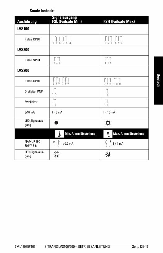
Sonde bedeckt
SignalausgangAusführung FSL (Failsafe Min) FSH (Failsafe Max)
LVS100
Relais DPDT
LVS200
Relais SPDT
LVS200
Relais DPDT
Dreileiter PNP
Zweileiter
8/16 mA I = 8 mA I = 16 mA
LED Signalaus-gang
Min. Alarm Einstellung Max. Alarm Einstellung
NAMUR IEC 60947-5-6
I >2,2 mA I < 1 mA
LED Signalaus-gang
8 7 6 5 4 3 7 6 5 4 38
3 4 5 3 4 5

Seite DE-18 SITRANS LVS100/200� BETRIEBSANLEITUNG 7ML19985FT63
mm
mm
m
Deut
sch
Optionen Signalausgang und Test (LVS200)
Signalausgang Verzögerung
Ausführung Allspannung (DPDT)
Für den Signalausgang kann eine Verzögerung von 0 bis 30 Sekunden eingestellt werden. Eine Drehung des Potentiometers im Uhrzeigersinn erhöht die Verzögerungszeit.Potentiometer T1: Verzögerung beim Umschalten von Sonde bedeckt - frei.Potentiometer T2: Verzögerung beim Umschalten von Sonde frei - bedeckt.
Testfunktion
NAMUR Ausführung (IEC 60947-5-6) und 8/16 mA oder 4 ... 20 mA Ausführung
Wenn die Sonde nicht bedeckt ist, wird durch Drücken der Taste die Schwingung gestoppt und das Ausgangssignal umgeschaltet, so dass Sonde bedeckt gemeldet wird. Dies erlaubt eine Prüfung der Schwingung und der Elektronik, ohne den LVS200 aus dem Behälter ausbauen zu müssen. Wenn die Sonde bedeckt ist, hat das Drücken der Taste keine Auswirkung.
Hinweis: Die unten aufgeführten Signalausgangs- und Testoptionen beziehen sich nur auf bestimmte Optionen der Spannungsversorgung.
Test-TasteElektronikmodul
LED Diagnose
NAMUR Ausführung
Einstellung der Empfindlichkeit:
B = WerkseinstellungA = verminderte
Empfindlichkeit
AB
7ML19985FT63 SITRANS LVS100/200 � BETRIEBSANLEITUNG Seite DE-19
mm
mm
m
Deutsch
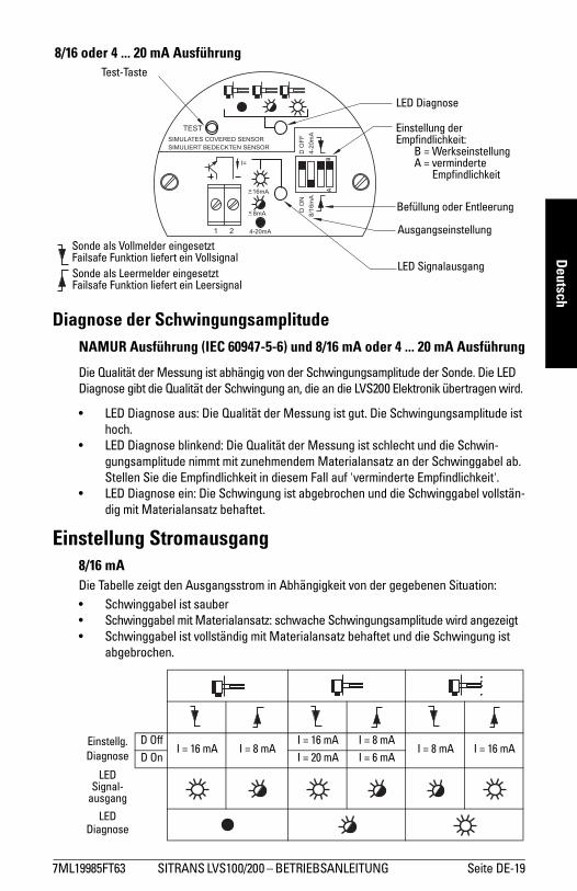
Diagnose der SchwingungsamplitudeNAMUR Ausführung (IEC 60947-5-6) und 8/16 mA oder 4 ... 20 mA Ausführung
Die Qualität der Messung ist abhängig von der Schwingungsamplitude der Sonde. Die LED Diagnose gibt die Qualität der Schwingung an, die an die LVS200 Elektronik übertragen wird.
� LED Diagnose aus: Die Qualität der Messung ist gut. Die Schwingungsamplitude ist hoch.
� LED Diagnose blinkend: Die Qualität der Messung ist schlecht und die Schwin-gungsamplitude nimmt mit zunehmendem Materialansatz an der Schwinggabel ab. Stellen Sie die Empfindlichkeit in diesem Fall auf 'verminderte Empfindlichkeit'.
� LED Diagnose ein: Die Schwingung ist abgebrochen und die Schwinggabel vollstän-dig mit Materialansatz behaftet.
Einstellung Stromausgang8/16 mADie Tabelle zeigt den Ausgangsstrom in Abhängigkeit von der gegebenen Situation:� Schwinggabel ist sauber� Schwinggabel mit Materialansatz: schwache Schwingungsamplitude wird angezeigt� Schwinggabel ist vollständig mit Materialansatz behaftet und die Schwingung ist
abgebrochen.
Einstellg. Diagnose
D OffI = 16 mA I = 8 mA
I = 16 mA I = 8 mAI = 8 mA I = 16 mA
D On I = 20 mA I = 6 mA
LED Signal-
ausgang
LED Diagnose
8/16 oder 4 ... 20 mA AusführungTest-Taste
LED Diagnose
Einstellung der Empfindlichkeit:
B = WerkseinstellungA = verminderte
Empfindlichkeit
BA
Befüllung oder Entleerung
Ausgangseinstellung
LED Signalausgang
Sonde als Vollmelder eingesetztFailsafe Funktion liefert ein VollsignalSonde als Leermelder eingesetztFailsafe Funktion liefert ein Leersignal

Seite DE-20 SITRANS LVS100/200� BETRIEBSANLEITUNG 7ML19985FT63
mm
mm
m
Deut
sch
Über den Ausgangsstrom kann eine schwache Schwingungsamplitude angezeigt werden (mit Diagnose Einstellung D ON). Bei der Diagnose Einstellung D OFF schaltet der Ausgang je nach Füllstandeinstellung (Min. oder Max.) zwischen 8 mA und 16 mA. Bei der Einstellung D ON schaltet der Ausgang bei schwacher Schwingungsamplitude von 16 auf 20 mA und von 8 auf 6 mA. Dies ermöglicht eine Auswertung an einem externen 4 ... 20 mA Ausgang. Der Übergang ist intern um 10 Sekunden verzögert. Dies verhindert, dass der externe Ausgang eine schwache Schwingung anzeigt, wenn die Schwingung während dem normalen Messvorgang gestoppt und wieder gestartet wird.
Erfassung von Materialansatz (8/16 mA oder 4 ... 20 mA Ausführung)
Bei der Einstellung 4 ... 20 mA ist es möglich, Materialansatz auf der Gabel durch eine SPS oder einen Datenlogger auszuwerten.
In diesem Modus ist die Diagnose-Einstellung ohne Bedeutung. Die LED für den Signal-ausgang ist aus.
20 mA: Die Schwinggabel ist sauber.
<20 mA und >12/12,5 mA: Die Schwingungsamplitude wird durch den Materialansatz ver-ringert.
<12/12,5 mA und >7/8 mA: Dieser Bereich zeigt eine schwache Schwingung an. Die interne LED für die Diagnose fängt zu blinken an, um ein schwaches Signal anzuzeigen. Bei Einsatz einer SPS zur Auswertung des Echos ist die Reaktionszeit dieses Anzeigers ca. 10 Sekunden zu verzögern. Eine Hysterese von 0,5 mA (zwischen 12 und 12,5 mA) wird empfohlen.
7/8 mA: Dieser Punkt zeigt an, dass die Schwinggabel großteils verkrustet ist.
6 mA: Dieser Punkt zeigt an, dass die Schwinggabel vollständig verkrustet ist.
Zunehmender Materialansatz
Amplitude: 100%
Amplitude: 0%
Amplitude: 100%
Amplitude: 0%
Bei normaler Empfindlichkeit Bei verminderter Empfindlichkeit
6 mA
7/8 mA
12/12,5 mA
20 mA
Ausg
angs
stro
m
normale Empfindlichkeit
verminderte Empfindlichkeit
Dämpfung der Schwingung durch Material
7ML19985FT63 SITRANS LVS100/200 � BETRIEBSANLEITUNG Seite DE-21
mm
mm
m
Deutsch
Wartung
Unter normalen Betriebsbedingungen erfordern die SITRANS LVS100/200 Sonden keine Wartung oder Reinigung. Unter schwierigen Betriebsbedingungen kann eine regelmä-ßige Reinigung der Schwinger erforderlich sein. Bürsten Sie eventuelle Materialablage-rungen ab und achten Sie dabei darauf, die Schwinger nicht zu verbiegen.
Gerätereparatur und HaftungsausschlussAlle Änderungen und Reparaturen müssen von qualifiziertem Personal unter Beachtung der jeweiligen Sicherheitsbestimmungen vorgenommen werden. Bitte beachten Sie:
� Der Benutzer ist für alle Änderungen und Reparaturen am Gerät verantwortlich.� Alle neuen Bauteile sind von Siemens Milltronics Process Instruments Inc. bereit zu
stellen.� Reparieren Sie lediglich defekte Bauteile.� Defekte Bauteile dürfen nicht wiederverwendet werden.

Seite DE-22 SITRANS LVS100/200� BETRIEBSANLEITUNG 7ML19985FT63
mm
mm
m
Deut
sch
SITRANS LVS200 Ausführung mit Rohrverlängerung
AufbauBenötigtes Werkzeug:
1. Öffnen Sie den Deckel des Gehäuses; entnehmen Sie das Elektronikmodul.2. Führen Sie das Sensorkabel durch das kundenseitige 1" Rohr und Gehäuse.3. Fügen Sie Schwinggabelteil, Verlängerungsrohr und Gehäuse mit dem 36 mm Gabel-
schlüssel zusammen. Die Rohrgewinde sind mit geeignetem Dichtungsstoff abzu-dichten.
4. Richten Sie die Gabel und die Orientierungsmarke so aus, wie es in der Maßzeich-nung auf Seite 12 gezeigt wird. (Die Orientierungsmarkierung auf dem Prozessan-schluss erlaubt, die Gabel vertikal auszurichten.)
5. Kürzen Sie das Sensorkabel auf eine freie Länge von 150 mm (5,9"). 6. Kürzen Sie das Erdungskabel auf eine freie Länge von 220 mm (8.7"). 7. Bereiten Sie das Sensorkabel wie oben abgebildet vor, indem Sie maximal 8 mm von
jeder Ader abisolieren.
� mittlerer Kreuzschraubenzieher oder 6 bis 8 mm (¼�) Schlitz-Schraubenzieher
� Quetschzange
� 3 mm (1/8") Schlitz-Schraubenzieher � 36 mm Gabelschlüssel
� Zangen � Rohrschlüssel
� Abstreifzangen
Hinweis: Nicht am Schwinggabelteil drehen. Die Gabel darf beim Zusammenbau nicht verbogen werden.
Gehäuse kundenseitiges Verlängerungsrohr
Schwinggabelteil
Erdungskabel (grün/gelb)220 mm
(8.7")
150 mm (5.9")
8 mm max.18 mm
7ML19985FT63 SITRANS LVS100/200 � BETRIEBSANLEITUNG Seite DE-23
mm
mm
m
Deutsch
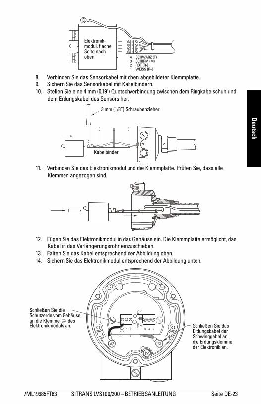
8. Verbinden Sie das Sensorkabel mit oben abgebildeter Klemmplatte.9. Sichern Sie das Sensorkabel mit Kabelbindern.10. Stellen Sie eine 4 mm (0,19") Quetschverbindung zwischen dem Ringkabelschuh und
dem Erdungskabel des Sensors her.
11. Verbinden Sie das Elektronikmodul und die Klemmplatte. Prüfen Sie, dass alle Klemmen angezogen sind.
12. Fügen Sie das Elektronikmodul in das Gehäuse ein. Die Klemmplatte ermöglicht, das Kabel in das Verlängerungsrohr einzuschieben.
13. Falten Sie das Kabel entsprechend der Abbildung oben. 14. Sichern Sie das Elektronikmodul entsprechend der Abbildung unten.
Elektronik-modul, flache Seite nach oben 4 = SCHWARZ (T)
3 = SCHIRM (M) 2 = ROT (R-) 1 = WEISS (R+)
3 mm (1/8�) Schraubenzieher
Kabelbinder
Schließen Sie die Schutzerde vom Gehäuse an die Klemme des Elektronikmoduls an. Schließen Sie das
Erdungskabel der Schwinggabel an die Erdungsklemme der Elektronik an.
Seite DE-24 SITRANS LVS100/200� BETRIEBSANLEITUNG 7ML19985FT63
mm
mm
m
Deut
sch
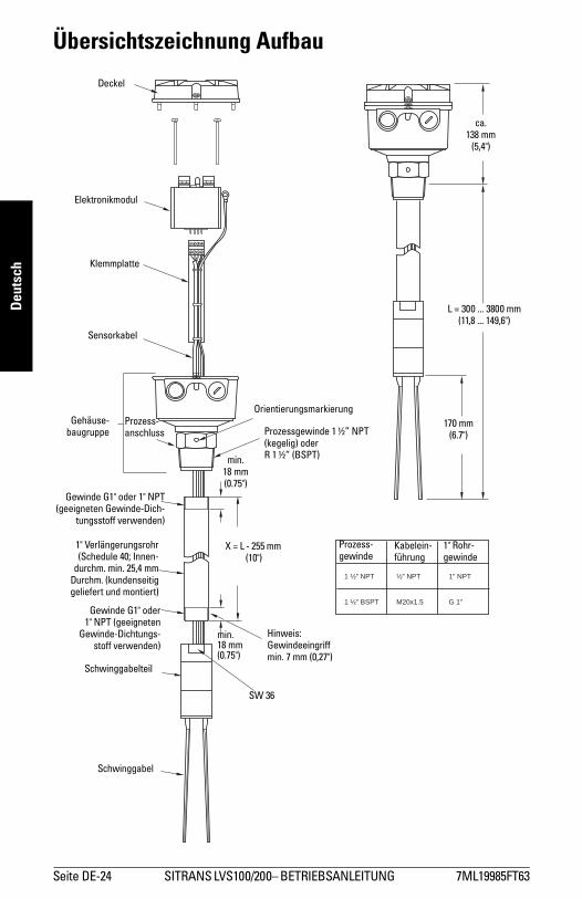
Übersichtszeichnung Aufbau
½” NPT
M20x1.5
1 ½” NPT
1 ½" BSPT
1" NPT
G 1"
Deckel
Elektronikmodul
Klemmplatte
Sensorkabel
Gehäuse-baugruppe
Prozess-anschluss
Orientierungsmarkierung
Prozessgewinde 1 ½� NPT (kegelig) oderR 1 ½� (BSPT)
Gewinde G1" oder 1" NPT(geeigneten Gewinde-Dich-
tungsstoff verwenden)
Schwinggabel
Schwinggabelteil
Gewinde G1" oder1" NPT (geeigneten
Gewinde-Dichtungs-stoff verwenden)
1" Verlängerungsrohr(Schedule 40; Innen-
durchm. min. 25,4 mmDurchm. (kundenseitiggeliefert und montiert)
X = L - 255 mm (10")
min. 18 mm (0.75")
min. 18 mm (0.75")
SW 36
Hinweis: Gewindeeingriff min. 7 mm (0,27")
ca. 138 mm
(5,4")
L = 300 ... 3800 mm (11,8 ... 149,6")
170 mm(6.7")
Prozess-gewinde
Kabelein-führung
1" Rohr-gewinde

7ML19985FT63 SITRANS LVS100/200 � MANUAL DE INSTRUCCIONES Página ES-1
mm
mm
m
Español
Indicaciones de seguridadEs imprescindible respetar las indicaciones de seguridad y advertencias indicadas en gris..
Indicaciones de seguridad
Acerca del manual
El presente manual contiene las informaciones necesarias para obtener el máximo rendimiento del SITRANS LVS100/LVS200. No dude en enviarnos sus sugerencias y comentarios acerca del contenido y diseño de este manual.Por favor dirija sus comentarios a [email protected]. Para más información acerca de la biblioteca de manuales Siemens Milltronics, consulte el sitio www.siemens.com/processautomation.
ADVERTENCIA: información que se refiere a un marcado colocado en el producto. Significa que al no observar las precauciones de seguridad se puede producir la muerte, lesiones corporales graves o daños materiales considerables.
ADVERTENCIA1: significa que al no observar las precauciones de seguridad se puede producir la muerte, lesiones corporales graves o daños materiales considerables.
PRECAUCIÓN: significa que al no observar las precauciones de seguridad se pueden producir daños materiales considerables.Importante: es una información importante acerca del producto mismo o de la parte respectiva del manual, al cual se debe atender especialmente.
1. Símbolo utilizado cuando el producto no lleva marcado de seguridad.
En el manual
En el producto Descripción
(Etiqueta del producto: fondo amarillo).Precaución: véase la documentación adjunta (manual del usuario).
Borne de tierra
Borne de conexión del conductor de protección
Indicaciones:� Para lograr una instalación correcta y optimizar el rendimiento del aparato deben tenerse
en cuenta las instrucciones de instalación y funcionamiento. SITRANS LVS100/200
� Este manual contiene instrucciones relativas a los aparatos SITRANS LVS100 y SITRANS LVS200.
� El contenido de este manual (detalles, instrucciones, ...) se refiere a los aparatos SITRANS LVS100 y SITRANS LVS200, salvo otra indicación.
� Este aparato se ha diseñado para el uso en ámbito industrial. El uso de este aparato en instalaciones residenciales puede causar interferencias a las comunicaciones por radio.
Página ES-2 SITRANS LVS100/200 � MANUAL DE INSTRUCCIONES 7ML19985FT63
mm
mm
m
Espa
ñol
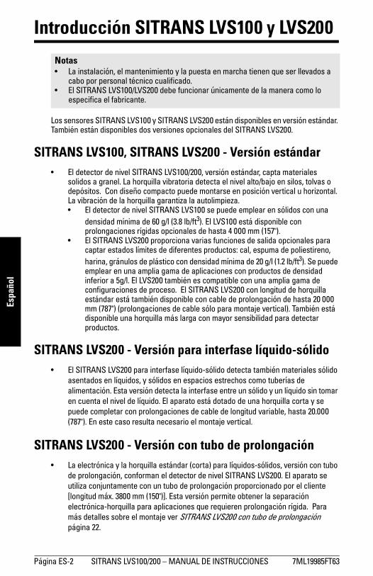
Introducción SITRANS LVS100 y LVS200
Los sensores SITRANS LVS100 y SITRANS LVS200 están disponibles en versión estándar. También están disponibles dos versiones opcionales del SITRANS LVS200.
SITRANS LVS100, SITRANS LVS200 - Versión estándar� El detector de nivel SITRANS LVS100/200, versión estándar, capta materiales
solidos a granel. La horquilla vibratoria detecta el nivel alto/bajo en silos, tolvas o depósitos. Con diseño compacto puede montarse en posición vertical u horizontal. La vibración de la horquilla garantiza la autolimpieza.� El detector de nivel SITRANS LVS100 se puede emplear en sólidos con una
densidad mínima de 60 g/l (3.8 lb/ft3). El LVS100 está disponible con prolongaciones rígidas opcionales de hasta 4 000 mm (157").
� El SITRANS LVS200 proporciona varias funciones de salida opcionales para captar estados límites de diferentes productos: cal, espuma de poliestireno, harina, gránulos de plástico con densidad mínima de 20 g/l (1.2 lb/ft3). Se puede emplear en una amplia gama de aplicaciones con productos de densidad inferior a 5g/l. El LVS200 también es compatible con una amplia gama de configuraciones de proceso. El SITRANS LVS200 con longitud de horquilla estándar está también disponible con cable de prolongación de hasta 20 000 mm (787") (prolongaciones de cable sólo para montaje vertical). También está disponible una horquilla más larga con mayor sensibilidad para detectar productos.
SITRANS LVS200 - Versión para interfase líquido-sólido� El SITRANS LVS200 para interfase líquido-sólido detecta también materiales sólido
asentados en líquidos, y sólidos en espacios estrechos como tuberías de alimentación. Esta versión detecta la interfase entre un sólido y un líquido sin tomar en cuenta el nivel de líquido. El aparato está dotado de una horquilla corta y se puede completar con prolongaciones de cable de longitud variable, hasta 20.000 (787"). En este caso resulta necesario el montaje vertical.
SITRANS LVS200 - Versión con tubo de prolongación� La electrónica y la horquilla estándar (corta) para líquidos-sólidos, versión con tubo
de prolongación, conforman el detector de nivel SITRANS LVS200. El aparato se utiliza conjuntamente con un tubo de prolongación proporcionado por el cliente [longitud máx. 3800 mm (150")]. Esta versión permite obtener la separación electrónica-horquilla para aplicaciones que requieren prolongación rígida. Para más detalles sobre el montaje ver SITRANS LVS200 con tubo de prolongación página 22.
Notas� La instalación, el mantenimiento y la puesta en marcha tienen que ser llevados a
cabo por personal técnico cualificado. � El SITRANS LVS100/LVS200 debe funcionar únicamente de la manera como lo
especifica el fabricante.
7ML19985FT63 SITRANS LVS100/200 � MANUAL DE INSTRUCCIONES Página ES-3
mm
mm
m
Español
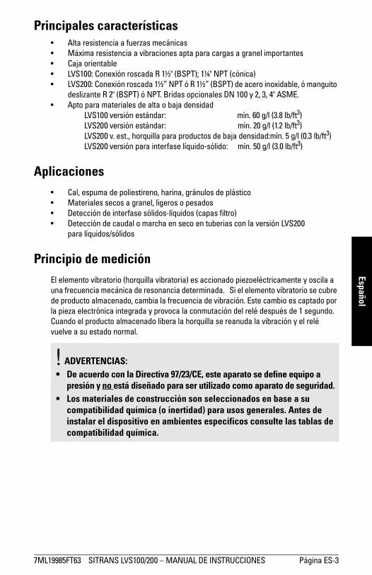
Principales características� Alta resistencia a fuerzas mecánicas� Máxima resistencia a vibraciones apta para cargas a granel importantes� Caja orientable� LVS100: Conexión roscada R 1½" (BSPT); 1¼" NPT (cónica)� LVS200: Conexión roscada 1½� NPT ó R 1½� (BSPT) de acero inoxidable, ó manguito
deslizante R 2" (BSPT) ó NPT. Bridas opcionales DN 100 y 2, 3, 4" ASME. � Apto para materiales de alta o baja densidad
LVS100 versión estándar: mín. 60 g/l (3.8 lb/ft3)LVS200 versión estándar: mín. 20 g/l (1.2 lb/ft3)LVS200 v. est., horquilla para productos de baja densidad:mín. 5 g/l (0.3 lb/ft3)LVS200 versión para interfase líquido-sólido: mín. 50 g/l (3.0 lb/ft3)
Aplicaciones� Cal, espuma de poliestireno, harina, gránulos de plástico� Materiales secos a granel, ligeros o pesados� Detección de interfase sólidos-líquidos (capas filtro)� Detección de caudal o marcha en seco en tuberias con la versión LVS200
para líquidos/sólidos
Principio de mediciónEl elemento vibratorio (horquilla vibratoria) es accionado piezoeléctricamente y oscila a una frecuencia mecánica de resonancia determinada. Si el elemento vibratorio se cubre de producto almacenado, cambia la frecuencia de vibración. Este cambio es captado por la pieza electrónica integrada y provoca la conmutación del relé después de 1 segundo. Cuando el producto almacenado libera la horquilla se reanuda la vibración y el relé vuelve a su estado normal.
ADVERTENCIAS:
• De acuerdo con la Directiva 97/23/CE, este aparato se define equipo a presión y no está diseñado para ser utilizado como aparato de seguridad.
• Los materiales de construcción son seleccionados en base a su compatibilidad química (o inertidad) para usos generales. Antes de instalar el dispositivo en ambientes específicos consulte las tablas de compatibilidad química.

Página ES-4 SITRANS LVS100/200 � MANUAL DE INSTRUCCIONES 7ML19985FT63
mm
mm
m
Espa
ñol
Datos técnicos
AlimentaciónLVS100
� 19 ... 230 V AC, +10 %, 50 ... 60 Hz, 8 VA / 19 ... 50 V DC, +10 %, 2 W
LVS200
� 19 ... 230 V AC, +10 %, 50 ... 60 Hz, 8 VA / 19 ... 55 V DC, +10 %, 1.5 W� 18 ... 50 V DC 3 hilos, PNP� 7 ... 9 V DC (requiere amplificador NAMUR) NAMUR IEC 60947-506-6, 2 hilos� 8/16 mA ó 4 ... 20 mA; 12.5 ... 35 V DC, 2 hilos
RendimientoFrecuencia de medición
LVS100
� estándar apróx. 200 HzLVS200
� estándar apróx. 125 Hz� versión para interfases líquidos-sólidosapróx. 350 Hz� opción sensibilidad aumentada apróx. 90 Hz
Tiempo de retardo
� en caso de cobertura de la horquilla apróx. 1 s� en caso de liberación de la horquilla apróx. 1 a 2 s
Tiempo de retardo (salida de relé DPDT) (LVS200)
� ajustable hasta 30 s
Sensibilidad
� alta o baja, selección por interruptor
Densidad mínima del producto
LVS100
� versión estándar apróx. 60 g/l (3.8 lb/ft3)LVS200
� versión estándar apróx. 20 g/l (1,2 lb/ft³)� versión est. para productos de baja densidad apróx. 5 g/l (0,3 lb/ft³)� versión para interfase líquido-sólido apróx. 50 g/l (3 lb/ft³)
Importante: Siemens Milltronics hace todo lo necesario para garantizar la exactitud de las especificaciones que figuran en este manual. Sin embargo, estas informaciones quedan sujetas a cambios sin preaviso.

7ML19985FT63 SITRANS LVS100/200 � MANUAL DE INSTRUCCIONES Página ES-5
mm
mm
m
EspañolMáximo tamaño de partícula
� LVS100 8 mm (0.32")� LVS200 10 mm (0.39")
Salida de alarmaLVS100
� versión doble relé, DPDTfail safe relé: alto/bajo, selección por interruptor. Relé 8 A a 250 V AC, cargaóhmica / relé 5 A a 30 V DC carga óhmica
LVS200
� versión relé sencillo, SPDTfail safe relé: alto/bajo, selección porinterruptor. Relé 8 A a 250 V AC, cargaóhmica / relé 5 A a 30 V DC, carga óhmica
� versión doble relé, DPDTfail safe relé: alto/bajo, selección por interruptor. Relé 8 A a 250 V AC, cargaóhmica / relé 5 A a 30 V DC carga óhmica
� 3 hilos, colector abierto PNP: carga contínua;máx. 0.4 A, prot.cortocircuito y sobrecarga; tensión de accionamiento: máx. 50 V (protección reversible)
� Salida mA (detección de incrustaciones) 8/16 mA ó 4 ... 20 mA; sensibilidad 4 - 20 mA, ±0,1 mA
Página ES-6 SITRANS LVS100/200 � MANUAL DE INSTRUCCIONES 7ML19985FT63
mm
mm
m
Espa
ñol
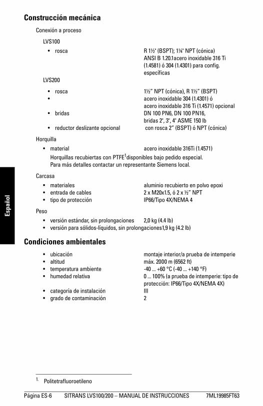
Construcción mecánicaConexión a proceso
LVS100
� rosca R 1½" (BSPT); 1¼" NPT (cónica) ANSI B 1.20.1acero inoxidable 316 Ti (1.4581) ó 304 (1.4301) para config. específicas
LVS200
� rosca 1½� NPT (cónica), R 1½� (BSPT)� acero inoxidable 304 (1.4301) ó
acero inoxidable 316 Ti (1.4571) opcional� bridas DN 100 PN6, DN 100 PN16,
bridas 2", 3", 4" ASME 150 lb� reductor deslizante opcional con rosca 2� (BSPT) ó NPT (cónica)
Horquilla
� material acero inoxidable 316Ti (1.4571)Horquillas recubiertas con PTFE1disponibles bajo pedido especial. Para más detalles contactar un representante Siemens local.
Carcasa
� materiales aluminio recubierto en polvo epoxi� entrada de cables 2 x M20x1.5, ó 2 x ½� NPT� tipo de protección IP66/Tipo 4X/NEMA 4
Peso
� versión estándar, sin prolongaciones 2,0 kg (4.4 lb)� versión para sólidos-líquidos, sin prolongaciones1,9 kg (4.2 lb)
Condiciones ambientales� ubicación montaje interior/a prueba de intemperie� altitud máx. 2000 m (6562 ft)� temperatura ambiente -40 ... +60 °C (-40 ... +140 °F)� humedad relativa 0 ... 100% (a prueba de intemperie: tipo de
protección: IP66/Tipo 4X/NEMA 4X)� categoría de instalación III� grado de contaminación 2
1. Politetrafluoroetileno

7ML19985FT63 SITRANS LVS100/200 � MANUAL DE INSTRUCCIONES Página ES-7
mm
mm
m
Español
Condiciones de servicioTemperatura
� Todas las homologaciones excepto CSA Clase II, Grupo G: �40 ... +150 °C (�40 ... +302 °F)
� CSA Clase II, Grupo G: �40 ... +140 °C (�40 ... +284 °F), código de temperatura CSA T3B
� Si la temperatura de proceso excede +80 °C (+176 °F), la temperatura en la superficie del reductor roscado no debe exceder +80 °C (+176 °F)
� Máx. temperatura en la superficie de la carcasa (Cat. 2D): +90 °C (+194 °F) (ATEX)� Máx. temp. en la superficie de la prolongación (Cat. 1D): +150 °C (+302 °F) (ATEX)
Presión
� máx. 10 bar (145 psi), presión efectiva
HomologacionesLVS100
� CE� ATEX II 1/2D� CSA/FM Clase II, III, Div. 1, Grupos E, F, G� C-TICK
LVS200
� CSA/FM uso general� CE� CSA/FM a prueba de explosión de polvo� ATEX II 1/2D� CSA/FM IS Clase I, II, III, Div. 1, Grupos A - G, FM Clase I, Aex ia IIC, CSA Clase 1,
Ex ia IIC, disponible sólo con alimentación 7 - 9 V DC y amplificador de conmutación NAMUR
� ATEX II 1G y 1/2G Eex ia IIC; ATEX II 1D y 1/2D, disponible sólo con alimentación 7 - 9 V DC y amplificador de conmutación NAMUR
� C-TICK
Importante: Presión en zonas con peligro de explosiónEl aparato está diseñado para soportar una sobrepresión máxima de 10 bar. Presión autorizada durante pruebas de funcionamiento. La certificación ATEX se aplica a una sobrepresión de �0,2 a 0,1 bar en zonas con peligro de explosión. La certificación sólo será valida para los valores indicados.

Página ES-8 SITRANS LVS100/200 � MANUAL DE INSTRUCCIONES 7ML19985FT63
mm
mm
m
Espa
ñol
Instalación
MontajeIndicaciones:� La instalación del aparato tiene que ser realizada sólo por personal especializado,
respetando las normas locales en vigor.� Es imprescindible no doblar, cortar o extender la horquilla.� La horquilla puede orientarse con una llave abierta de 50 mm durante la instalación
de la conexión a proceso. No girar la carcasa. En caso de montaje vertical del detector SITRANS LVS200 gire la horquilla vibratoria verticalmente y atienda que las marcas se encuentren orientadas hacia arriba/abajo.
� En el caso de presión excesiva o vacío en el depósito, envolver las roscas de conexión (tubuladuras) con cinta de PTFE (o similar).
� Girar hacia abajo los racores atornillados para cables de los aparatos montados horizontalmente para evitar la penetración de humedad en la caja.
� Prestar atención a no aplicar un par de apriete superior a 250 Nm a los detectores SITRANS LVS100/LVS200 con prolongación (fuerza relacionada con la carga de producto en el punto de montaje).
� La conexión roscada 1½" puede soportar un par máximo de montaje de 80 Nm.
ADVERTENCIAS, LVS100 y LVS200:• De acuerdo con la Directiva 97/23/CE, este aparato se define como
equipo a presión y no está diseñado para ser utilizado como aparato de seguridad.
• La instalación incorrecta puede provocar una caída de presión del proceso.
• En áreas con peligro de explosión hay que atender las prescripciones y las instrucciones específicas de seguridad.
• En el caso de aplicaciones ATEX la instalación se efectuará de acuerdo a lo especificado en la norma EN 50281-1-2 relativo a adherencias de polvo y temperaturas. Antes de abrir la caja, prestar atención a posibles incrustaciones en el aparato.
• No abrir la caja del aparato mientras los circuitos estén bajo tensión.• Instalar el SITRANS LVS100/200 de forma tal que la fricción mecánica
o el impacto entre la caja de aluminio y el depósito de acero no produzcan chispas.
LVS200:• Instalación en Zona 0 (electrónica: NAMUR): al utilizar un circuito de
seguridad intrínseca debe prestarse atención a garantizar el aislamiento galvánico hacía una zona no intrínsecamente segura. De lo contrario, proteger el aparato de las descargas eléctricas (ver EN 60079-14).
• Alimentación eléctrica (electrónica: NAMUR): Para garantizar la seguridad intrínseca sólo puede conectarse a una fuente intrínsecamente segura certificada.
• SITRANS LVS, modelos con tubo y cable de prolongación, electrónica NAMUR para atmósferas explosivas con gases: Al instalar el aparato en la tapa del depósito que separa la Zona 0 (Cat. 1G) de la Zona 1 (Cat 2G), no podrá garantizarse la separación segura entre la Zona 0 y la Zona 1. El gas se puede extender de la Zona 0 a la Zona 1 pasando por la caja del aparato.

7ML19985FT63 SITRANS LVS100/200 � MANUAL DE INSTRUCCIONES Página ES-9
mm
mm
m
EspañolEl SITRANS LVS100/200 está diseñado para el montaje vertical (captación de nivel límite máx.) u horizontal (captación de nivel límite máx. o mín. o de nivel de llenado deseado).
Observaciones relativas al proceso
Girar hacia abajo el racor atornillado para cables de los aparatos montados horizontalmente para evitar la penetración de agua.
Protección contra eventuales fuerzas intensas.
El montaje inclinado solo es aconsejable para materiales poco densos. Si se requiere el montaje inclinado en aplicaciones con fuerzas laterales intensas, instalar la protección provista por el cliente.
*máxima
inclinaciónα
máx. longitud L
5º 4 m45º 1,2 m
>45º 0,6 m
*
L
Marcas laterales de orientación de la horquilla.
α
Colocar el detector verticalmente para mantener al mínimo las incrustaciones sobre la horquilla vibratoria: gire la conexión a proceso con una llave abierta (50 mm) y atienda que las marcas se encuentren orientadas hacia arriba/abajo.
Prolongación rígida con manguito deslizante
Versión con cable de prolongación
Precaución:� Instalar el SITRANS LVS100/LVS200
lejos de la caída de material.� Proteger el eje y la horquilla de la caída
de materialo

Página ES-10 SITRANS LVS100/200 � MANUAL DE INSTRUCCIONES 7ML19985FT63
mm
mm
m
Espa
ñol
Dimensiones - SITRANS LVS100
120 mm (4.72")
150 mm (5.91")
brida (proceso) provista por el cliente
170 ... 4000 mm (6.69 ... 157"): prolongación rigida según las especificaciones del cliente
125 mm (4.92"): horquilla estándar
60 mm (2.36")
60 mm (2.36") 75 mm
(2.95")
marca de orientación de la horquilla
Zona 21(Cat. 2)
Zona 20(Cat. 1)
reductor roscado [máx. temp. +80°C (+176°F)]
horquilla

7ML19985FT63 SITRANS LVS100/200 � MANUAL DE INSTRUCCIONES Página ES-11
mm
mm
m
Español
Dimensiones - SITRANS LVS200
120 mm (4.72")
150 mm (5.91")
brida (proceso) provista por el cliente
165 mm (6.5"): versión compacta para interfases sólidos-líquidos230 mm (9,0"):versión compacta estándar300 ... 4000 mm (11,81 ... 157"): prolongación rigida según las especificaciones del cliente
170 mm (6.69"): horquilla estándar
195 mm (7.68"):horquilla para
productos de baja densidad
100 mm (3.94"): líquido/sólido
horquilla (pequeña)
60 mm (2.36")
60 mm (2.36")
75 mm (2.95")
marca de orientación de la horquilla
Zona 21(Cat. 2)
Zona 20(Cat. 1)
reductor roscado [máx. temp. +80°C (+176°F)]
reductor deslizante opcional*
*Nota: Máximo apriete de los tornillos de fijación del reductor: 10 Nm.
** Versión de cable, interfase líquido-sólido con longitud opcional hasta 7000 mm (275.59")Versión de cable con electrónica NAMUR, máx. longitud 10.000 mm (393.7'')
horquilla
100 mm (3,94"): versión para interfases sólidos-líquidos
Versión de cable
195 mm (7.68")
700 ... 20 000 mm** (27.56 ... 787")
155 mm (6.1")
ø 42 mm (1,67")
ø 42 mm (1,67")

Página ES-12 SITRANS LVS100/200 � MANUAL DE INSTRUCCIONES 7ML19985FT63
mm
mm
m
Espa
ñol
Cableado
Recomendaciones para la conexión� Proteger la señal de salida con un fusible (máximo 10 A).� Al utilizar cargas inductivas es imprescindible proteger los contactos de relés para
proteger el sistema de picos.
Precauciones� Antes de abrir la tapa compruebe que no hay depósitos o incrustaciones de polvo a
proximidad del SITRANS LVS100/200. Espere que la atmósfera alrededor del sensor se estabilice.
� La tensión de suministro no deberá exceder la máxima tensión indicada en la etiqueta del producto.
� Para evitar el contacto con componentes bajo tensión sólo deberá descubrirse una sección (8 mm) de los conductores.
� Proteger las terminaciones de los cables con manguitos que no excedan 8 mm para evitar el contacto con componentes bajo tensión.
ADVERTENCIAS:• Antes de abrir el SITRANS LVS100/200, comprobar que la alimentación
eléctrica esté desconectada.• Todos los cableados deben ser protegidos para 250 V AC. • Deberá proveerse un interruptor de desconexión fácilmente
accessible a proximidad del detector.• Utilizar prensaestopas para cables o conductos especiales en zonas
clasificadas. Cerrar los conductos inutilizados con elementos o tapones apropiados.
• Observar las normas y disposiciones pertinentes en el país donde se va a utilizar el aparato.
Indicaciones:Estándares europeos� En caso de aplicaciones Ex instalar prensaestopas y racores atornillados para
cables conformes ATEX 100a (protección antideflagrante). El rango de temperatura mínima debe ser -40 ... +70°C (-40 ... +158°F). Deberán satisfacerse los requisitos mínimos de protección (IP6x) definidos por la norma europea EN 60529. La utilización de prensaestopas está sometida a las condiciones especiales definidas en la documentación de certificación.
� La instalación cumplirá con los requisitos de la norma europea EN 50281-1-2 en cuanto a depósitos de polvo y temperaturas.
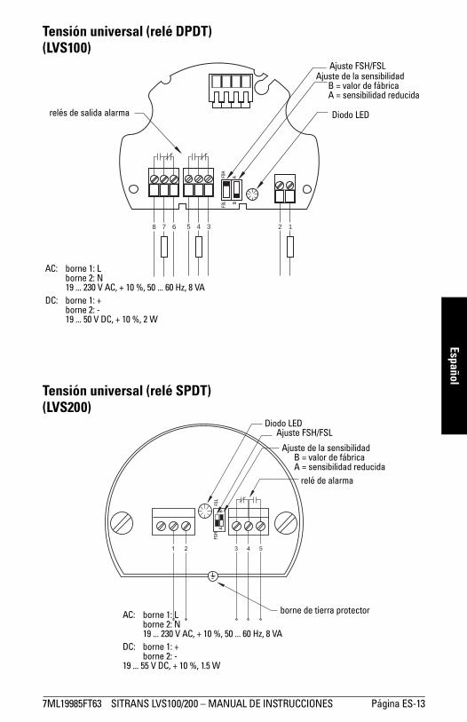
7ML19985FT63 SITRANS LVS100/200 � MANUAL DE INSTRUCCIONES Página ES-13
mm
mm
m
Español
Tensión universal (relé DPDT)(LVS100)
Tensión universal (relé SPDT)(LVS200)
12345678
relés de salida alarma
Ajuste FSH/FSLAjuste de la sensibilidad
B = valor de fábrica A = sensibilidad reducida
AC: borne 1: Lborne 2: N19 ... 230 V AC, + 10 %, 50 ... 60 Hz, 8 VA
DC: borne 1: +borne 2: -19 ... 50 V DC, + 10 %, 2 W
AB
FSH
FSL
Diodo LED
relé de alarma
Ajuste FSH/FSL
Ajuste de la sensibilidadB = valor de fábrica A = sensibilidad reducida
AC: borne 1: Lborne 2: N19 ... 230 V AC, + 10 %, 50 ... 60 Hz, 8 VA
DC: borne 1: +borne 2: -
19 ... 55 V DC, + 10 %, 1.5 W
borne de tierra protector
AB
FSH
FSL
Diodo LED

Página ES-14 SITRANS LVS100/200 � MANUAL DE INSTRUCCIONES 7ML19985FT63
mm
mm
m
Espa
ñol
Tensión universal (relé DPDT) 3 hilos PNP(LVS200) (LVS200)
2 hilos NAMUR IEC 60947-5-6 8/16 mA ó 4 ... 20 mA(LVS200) (LVS200) (LVS200)
PE +L
-N
relés de salida alarmaPE + -
carga
AC: borne 1: Lborne 2: N19 ... 230 V AC, + 10 %, 50 ... 60 Hz, 18 VA
DC: borne 1: +borne 2: -19 ... 55 V DC, + 10 %, 2 W
DC: borne 1: +borne 2: -18 ... 50 V DC, + 10 %, 1.5 W
PE +L
-N PE + - PE + -
AC: borne 1: Lborne 2: N19 ... 230 V AC, + 10 %,
50 ... 60 Hz, 1.5 VADC: borne 1: +
borne 2: -19 ... 230 V DC, + 10 %, 1 W
aprox. 7 ... 9 V DC, intrínsecamente seguro(IEC 60947-5-6)
DC: borne 1: +borne 2: -12,5 ... 36 V DC, + 0 %
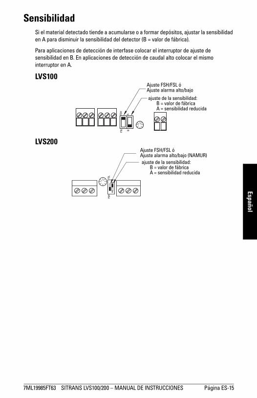
7ML19985FT63 SITRANS LVS100/200 � MANUAL DE INSTRUCCIONES Página ES-15
mm
mm
m
Español
SensibilidadSi el material detectado tiende a acumularse o a formar depósitos, ajustar la sensibilidad en A para disminuir la sensibilidad del detector (B = valor de fábrica).
Para aplicaciones de detección de interfase colocar el interruptor de ajuste de sensibilidad en B. En aplicaciones de detección de caudal alto colocar el mismo interruptor en A.
LVS100
LVS200
Ajuste FSH/FSL ó Ajuste alarma alto/bajo
ajuste de la sensibilidad:B = valor de fábricaA = sensibilidad reducida
FSH
FSL
AB
Ajuste FSH/FSL ó Ajuste alarma alto/bajo (NAMUR)ajuste de la sensibilidad:
B = valor de fábricaA = sensibilidad reducida
FSH
FSL
AB

Página ES-16 SITRANS LVS100/200 � MANUAL DE INSTRUCCIONES 7ML19985FT63
mm
mm
m
Espa
ñol
Lógica de conmutaciónHorquilla destapada
Señal de salida Versión/Modelo Fail-safe bajo (FSL) Fail-safe alto (FSH)
LVS100
Relé DPDT
LVS200
Relé SPDT
LVS200
Relé DPDT
3 hilos PNP
2 hilos
8/16 mA I = 16 mA I = 8 mA
Diodo LED señal de salida
Ajuste alarma baja Ajuste alarma alta
NAMUR IEC 60947-5-6
I < 1 mA I > 2,2 mA
Diodo LED señal de salida
7 6 5 4 38 8 7 6 5 4 3
3 4 5 3 4 5
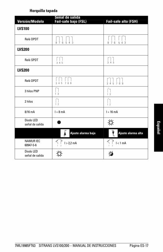
7ML19985FT63 SITRANS LVS100/200 � MANUAL DE INSTRUCCIONES Página ES-17
mm
mm
m
Español
Horquilla tapada
Señal de salidaVersión/Modelo Fail-safe bajo (FSL) Fail-safe alto (FSH)
LVS100
Relé DPDT
LVS200
Relé SPDT
LVS200
Relé DPDT
3 hilos PNP
2 hilos
8/16 mA I = 8 mA I = 16 mA
Diodo LED señal de salida
Ajuste alarma baja Ajuste alarma alta
NAMUR IEC 60947-5-6
I > 2,2 mA I < 1 mA
Diodo LED señal de salida
8 7 6 5 4 3 7 6 5 4 38
3 4 5 3 4 5

Página ES-18 SITRANS LVS100/200 � MANUAL DE INSTRUCCIONES 7ML19985FT63
mm
mm
m
Espa
ñol
Señal de salida y opciones de verificación (LVS200)
Retardo de señal de salidaVersion de alimentación universal (DPDT)
El usuario puede ajustar la señal de salida de 0 a 30 segudos. Girar el potenciómetro en sentido horario para aumentar el tiempo de retardo.
Potenciómetro T1: Tiempo de retardo en caso de conmutación de la salida (cobertura/liberación de la horquilla).
Potenciómetro T2: Tiempo de retardo en caso de conmutación de la salida (liberación/cobertura de la horquilla).
Control de funcionamientoVersión NAMUR (IEC 60947-5-6) y versión 8/16 mA ó 4 ... 20 mA
En caso de liberación de la horquilla, esta tecla permite parar la vibración y provocar la conmutación de la señal de salida para indicar la cobertura de la horquilla. El usuario puede realizar pruebas para comprobar el funcionamiento (vibración, electrónica) sin desmontar el LVS200. Esta tecla no se puede utilizar si la horquilla se cubre de producto almacenado.
Importante: El señal de salida y las opciones de verificación indicadas a continuación sólo se refieren a opciones específicas de alimentación eléctrica.
Tecla de control
Electrónica
Diodo LED
Versión NAMUR
ajuste de la sensibilidad:B = valor de fábricaA = sensibilidad reducida
AB
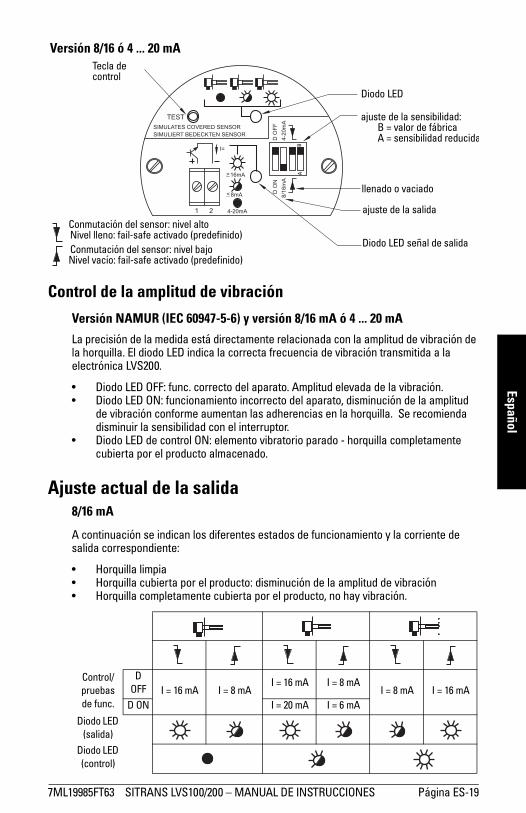
7ML19985FT63 SITRANS LVS100/200 � MANUAL DE INSTRUCCIONES Página ES-19
mm
mm
m
Español
Control de la amplitud de vibración
Versión NAMUR (IEC 60947-5-6) y versión 8/16 mA ó 4 ... 20 mA
La precisión de la medida está directamente relacionada con la amplitud de vibración de la horquilla. El diodo LED indica la correcta frecuencia de vibración transmitida a la electrónica LVS200.
� Diodo LED OFF: func. correcto del aparato. Amplitud elevada de la vibración.� Diodo LED ON: funcionamiento incorrecto del aparato, disminución de la amplitud
de vibración conforme aumentan las adherencias en la horquilla. Se recomienda disminuir la sensibilidad con el interruptor.
� Diodo LED de control ON: elemento vibratorio parado - horquilla completamente cubierta por el producto almacenado.
Ajuste actual de la salida8/16 mA
A continuación se indican los diferentes estados de funcionamiento y la corriente de salida correspondiente:
� Horquilla limpia� Horquilla cubierta por el producto: disminución de la amplitud de vibración� Horquilla completamente cubierta por el producto, no hay vibración.
Control/pruebas de func.
D OFF I = 16 mA I = 8 mA
I = 16 mA I = 8 mAI = 8 mA I = 16 mA
D ON I = 20 mA I = 6 mA
Diodo LED (salida)
Diodo LED (control)
Versión 8/16 ó 4 ... 20 mATecla de control
Diodo LED
ajuste de la sensibilidad:B = valor de fábricaA = sensibilidad reducida
BA
llenado o vaciado
ajuste de la salida
Diodo LED señal de salida
Conmutación del sensor: nivel altoNivel lleno: fail-safe activado (predefinido)Conmutación del sensor: nivel bajoNivel vacío: fail-safe activado (predefinido)

Página ES-20 SITRANS LVS100/200 � MANUAL DE INSTRUCCIONES 7ML19985FT63
mm
mm
m
Espa
ñol
La corriente de salida puede indicar una disminución de la amplitud de vibración con D ON (activado). Con el control D OFF (desactivado) se obtiene una salida 8 mA ó 16 mA en función de los ajustes de nivel alto/bajo.
Con el control D ON, la salida cambia de 16 a 20 mA y de 8 a 6 mA si la vibración disminuye. Esta salida se puede transmitir hacia una salida 4 ... 20 mA externa. Un tiempo de retardo de 10 segundos (ajustado de fábrica) impide la activación inmediata de la salida externa y la indicación de una frecuencia incorrecta de vibración en caso de accionamiento/paro del elemento vibratorio (horquilla) durante el funcionamiento normal.
Detección de incrustaciones de producto (versión 8/16 mA ó 4 ... 20 mA)
Con los valores 4 ... 20 mA pueden detectarse incrustaciones de producto en la horquilla directamente à través de un PLC o de un registrador de datos.
Este modo de operación es completamente independiente de las funciones de control. El diodo LED señal de salida está desactivado.
20 mA: horquilla limpia.
<20 mA y >12/12,5 mA: Disminución de la amplitud de vibración provocada por incrustaciones de producto.
<12/12,5 mA y >7/8 mA: Valores relacionados con una disminución de la amplitud de vibración. Activación del diodo LED interno (control) indica una señal insuficiente. Para evaluar señales con un PLC, aumentar el tiempo de reacción indicador (+ apróx. 10 segundos). Histérésis recomendada: 0,5 mA (entre 12 y 12,5 mA).
7/8 mA: Este punto indica que la horquilla está casi completamente cubierta por el producto almacenado.
6 mA: Este punto indica que la horquilla está completamente cubierta por el producto.aumento de las incrustaciones de producto
Amplitud 100%
Amplitud 0%
Amplitud 100%
Amplitud 0%
Sensibilidad estándar Sensibilidad disminuida
6 mA
7/8 mA
12/12,5 mA
20 mA
corr
ient
e de
sal
ida sensibilidad estándar
disminución de la sensibilidad
Amortiguamiento de vibraciones (producto)

7ML19985FT63 SITRANS LVS100/200 � MANUAL DE INSTRUCCIONES Página ES-21
mm
mm
m
Español
Mantenimiento
Al funcionar en condiciones normales, el SITRANS LVS100/200 no necesita mantenimiento o limpieza. En condiciones extremas, es recomendable la limpieza periódica de la horquilla. Utilizar un cepillo apropiado para eliminar los depósitos de producto sin doblar las láminas.
Reparaciones y límite de responsabilidadSólo el personal cualificado está autorizado a intervenir en este equipo. Las modificaciones y reparaciones deberán efectuarse respetando los códigos de práctica aplicables. Nota importante:
� El usuario es el único responsable de las modificaciones y reparaciones efectuadas en el dispositivo.
� Recomendamos utilizar sólo recambios originales Siemens Milltronics Process Instruments Inc.
� Reparar sólo los componentes defectuosos.� No reutilizar los componentes defectuosos.

Página ES-22 SITRANS LVS100/200 � MANUAL DE INSTRUCCIONES 7ML19985FT63
mm
mm
m
Espa
ñol
SITRANS LVS200 con tubo de prolongación
MontajeHerramientas recomendadas:
1. Abrir la tapa de la caja y retirar la electrónica.2. Insertar el cable del sensor en el tubo de 1" proporcionado por el cliente y en la caja.3. Utilizar la llave fija de 36 mm para montar el conjunto horquilla-tubo de
prolongación-caja. Hermetizar las roscas de las tubuladuras aplicando una cinta adecuada.
4. Atienda que la horquilla esté alineada con las marcas como se ilustra en la página página 12. (Las marcas en la horquilla caracterizan el punto de conexión en montaje vertical.)
5. Cortar el cable del sensor a la longitud deseada [150 mm (5,9"] 6. Cortar el cable de tierra a la longitud deseada [220 mm (8,7"] 7. Preparar el cable del sensor como se illustra arriba, pelando hasta 8 mm (máx.) de
cada conductor.
� destornillador plano mediano Phillips ó 6 - 8 mm (¼�) � pinza para terminales
� destornillador plano 3 mm (1/8�) � llave fija 36 mm
� cortacables � llave de cadena
� peladores de cable
Importante: Es imprescindible no girar el conjunto horquilla. No doblar la horquilla durante el montaje.
caja provisto por el cliente tubo de prolongación
horquilla
cable de tierra (verde/amarillo)220 mm
(8.7")
150 mm (5.9")
máx. 8 mm18 mm

7ML19985FT63 SITRANS LVS100/200 � MANUAL DE INSTRUCCIONES Página ES-23
mm
mm
m
Español
8. Conectar el cable del sensor en la placa de bornes como se ilustra arriba.9. Fijar el cable del sensor con retenedores adecuados.10. Pinzar el terminal 4 mm (0,19") en el cable de tierra del sensor.
11. Conectar la electrónica y la placa de bornes. Comprobar el apriete adecuado de los terminales.
12. Insertar la electrónica en la caja. La placa de bornes sirve también para guiar el cable e insertarlo en el tubo de extensión.
13. Doblar el cable como se ilustra en la figura precedente. 14. Sujetar la electrónica como se ilustra en la figura a continuación.
electrónica, lado plano hacia arriba
4 = NEGRO (T) 3 = BLINDAJE (M) 2 = ROJO (R-) 1 = BLANCO (R+)
destornillador 3 mm (1/8�)
retenedores
Conectar la tierra de protección de la caja en el terminal correspondiente de la electrónica. Conectar el cable
de tierra de la horquilla en el terminal de tierra correspondiente de la electrónica.

Página ES-24 SITRANS LVS100/200 � MANUAL DE INSTRUCCIONES 7ML19985FT63
mm
mm
m
Espa
ñol
Diagrama de conjunto
½” NPT
M20x1.5
1 ½” NPT
1 ½" BSPT
1" NPT
G 1"
tapa
electrónica
placa de bornes
cable del sensor
conjuntocaja
conexión al proceso
marca de orientación de la horquilla
conexión de proceso roscada 1 ½� NPT (cónica) óR 1 ½� (BSPT)
rosca G1� ó 1" NPT(utilizar un sellador
adecuado para roscas)
horquilla
horquilla
rosca G1� ó 1" NPT(utilizar un sellador
adecuado pararoscas)
Tubo 1" (SCH. 40)(diámetro interior
mínimo 25,4 mm(proporcionado y
montado por el cliente)
X = L - 255 mm (10")
mín. 18 mm (0.75")
mín. 18 mm (0.75")
SW 36
Importante: Sección enroscada 7 mm mínimo (0,27")
138 mm (5,4") aproxima-damente
L = 300 ... 3800 mm (11,8 ... 149,6")
170 mm(6.7")
conexión de proceso roscada
entradas de cables
roscado 1" NPT (tubo)

7ML19985FT63 SITRANS LVS100/200 � MANUEL D'UTILISATION Page FR-1
mm
mm
m
Français
Remarques concernant la sécuritéUne attention particulière doit être accordée aux avertissements et aux notes mis en évidence en gris..
Symboles de sécurité
Le manuel d'utilisation
Ce document vous permettra de paramétrer le SITRANS LVS100/200 pour obtenir des résultats optimaux. N�hésitez pas à nous faire part de vos commentaires et suggestions sur le contenu, la présentation et l�utilisation de ce manuel.
Veuillez transmettre tout commentaire à [email protected]. Pour une liste exhaustive des manuels Siemens Milltronics disponibles, consulter www.siemens.com/processautomation.
AVERTISSEMENT : fait référence à une mention sur le produit. Signifie que la mort, des blessures corporelles graves et/ou des dommages matériels conséquents peuvent se produire si les dispositions de sécurité correspondantes ne sont pas respectées.AVERTISSEMENT 1: signifie que la mort, des blessures corporelles graves et/ou des dommages matériels conséquents peuvent se produire si les dispositions de sécurité correspondantes ne sont pas respectées.PRECAUTION : signifie que des dommages matériels conséquents
peuvent se produire si les dispositions de sécurité correspondantes ne sont pas respectées.N.B. : information importante concernant le produit ou une section particulière de la notice d�utilisation.
1. Ce symbole est utilisé lorsque le produit ne comporte pas un marquage de sécurité.
Dans le manuel
Marquage sur le produit
Description
(Etiquette sur le produit ; fond jaune).Précaution : pour plus de détails consulter le manuel d�utilisation fourni.
Borne de mise à la terre
Borne de raccordement conducteur de protection
� Pour garantir la précision, la fiabilité et l�installation optimale de votre système SITRANS LVS100/200 il est impératif de respecter les instructions relatives à l�installation et au fonctionnement.
� Ce manuel décrit les détecteurs SITRANS LVS100 et SITRANS LVS200.� Sauf indication contraire, les détails et instructions s'appliquent aux détecteurs
SITRANS LVS100 et SITRANS LVS200.� Cet instrument est conçu pour une utilisation en milieu industriel. Utilisé en zone
résidentielle, cet appareil peut provoquer des perturbations des communications radio.

Page FR-2 SITRANS LVS100/200 � MANUEL D'UTILISATION 7ML19985FT63
mm
mm
m
Fran
çais
Introduction aux détecteurs SITRANS LVS100 et LVS200
Les détecteurs SITRANS LVS100 et SITRANS LVS200 sont disponibles en version standard mais aussi en deux versions complémentaires.
SITRANS LVS100, SITRANS LVS200 - Version standard� Les détecteurs à lames vibrantes SITRANS LVS100/200 standard sont destinés à la
détection de niveau haut/bas de matériaux solides dans les réservoirs, les silos ou les trémies. Petits, compacts, des détecteurs supportent le montage horizontal ou vertical. L'oscillation de la fourche maintient les lames libres de toute accumulation de produit.� Le SITRANS LVS100 est un détecteur à lames vibrantes pour matériau solides
ayant une densité min. de 60 g/l (3.8 lb/ft3). Le LVS100 est disponible avec une rallonge rigide, longueur max. 4 000 mm (157").
� SITRANS LVS200 est doté de plusieurs sorties permettant la détection de niveau de différents produits : chaux, mousse de polystyrène, farine et granulés plastique, ayant une densité min. de 20 g/l (1.2 lb/ft3). Ce détecteur s'adapte à une plus large gamme d'applications et convient aux produits ayant une densité inférieure à 5 g/l. Ceci est valable aussi pour les raccords process, le LVS200 offre plus de choix. Le détecteur SITRANS LVS200 standard peut être équipé d'une rallonge câble jusqu'à 20 000 mm (787") (rallonges câble pour montage vertical uniquement). Une fourche étendue disponible en option offre plus de fiabilité.
SITRANS LVS200 - pour interface liquide/solide� Le SITRANS LVS200 pour interfaces liquides/solides détecte les solides tassés dans
les liquides, ou les solides dans les ambiances confinées telles que les conduites d�alimentation. Cette version est conçue pour détecter la surface de séparation (interface) entre un solide et un liquide, sans tenir compte du liquide. Le détecteur est équipé d'une fourche courte, avec des rallonges câble en option, longueurs jusqu'à 20 000 mm (787") (montage vertical uniquement).
SITRANS LVS200 - Version avec tube prolongateur� Le SITRANS LVS200 doté d'un tube prolongateur comporte une fourche et une
électronique LVS200 standard (courte) pour liquides/solides. Il est doté d'une rallonge fournie par le client [longueur max. 3800 mm (150'')]. On obtient ainsi la séparation électronique/fourche là où la sonde doit être équipée d'une rallonge rigide. Pour plus de détails sur l'assemblage consulter la section SITRANS LVS200 version avec tube prolongateur page 22.
N.B. :� L�installation, la mise en service et la maintenance doivent être effectuées par un
personnel qualifié.� Les SITRANS LVS100/200 doivent être utilisés suivant les instructions fournies
dans ce manuel.
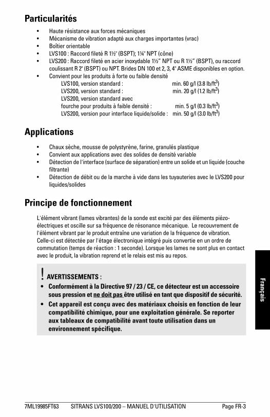
7ML19985FT63 SITRANS LVS100/200 � MANUEL D'UTILISATION Page FR-3
mm
mm
m
Français
Particularités� Haute résistance aux forces mécaniques� Mécanisme de vibration adapté aux charges importantes (vrac)� Boîtier orientable� LVS100 : Raccord fileté R 1½" (BSPT); 1¼" NPT (cône)� LVS200 : Raccord fileté en acier inoxydable 1½� NPT ou R 1½� (BSPT), ou raccord
coulissant R 2" (BSPT) ou NPT. Brides DN 100 et 2, 3, 4" ASME disponibles en option. � Convient pour les produits à forte ou faible densité
LVS100, version standard : min. 60 g/l (3.8 lb/ft3)LVS200, version standard : min. 20 g/l (1.2 lb/ft3)LVS200, version standard avec fourche pour produits à faible densité : min. 5 g/l (0.3 lb/ft3)LVS200, version pour interface liquide/solide : min. 50 g/l (3.0 lb/ft3)
Applications� Chaux sèche, mousse de polystyrène, farine, granulés plastique� Convient aux applications avec des solides de densité variable� Détection de l'interface (surface de séparation) entre un solide et un liquide (couche
filtrante)� Détection de débit ou de la marche à vide dans les tuyauteries avec le LVS200 pour
liquides/solides
Principe de fonctionnementL'élément vibrant (lames vibrantes) de la sonde est excité par des éléments piézo-électriques et oscille sur sa fréquence de résonance mécanique. Le recouvrement de l'élément vibrant par le produit entraîne une variation de la fréquence de vibration. Celle-ci est détectée par l'étage électronique intégré puis convertie en un ordre de commutation (temps de réaction : 1 seconde). Lorsque les lames ne sont plus en contact avec le produit, la vibration reprend et le relais est mis au repos.
AVERTISSEMENTS :
• Conformément à la Directive 97 / 23 / CE, ce détecteur est un accessoire sous pression et ne doit pas être utilisé en tant que dispositif de sécurité.
• Cet appareil est conçu avec des matériaux choisis en fonction de leur compatibilité chimique, pour une exploitation générale. Se reporter aux tableaux de compatibilité avant toute utilisation dans un environnement spécifique.
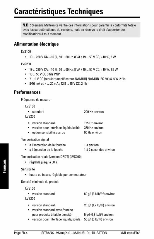
Page FR-4 SITRANS LVS100/200 � MANUEL D'UTILISATION 7ML19985FT63
mm
mm
m
Fran
çais
Caractéristiques Techniques
Alimentation électriqueLVS100
� 19 ... 230 V CA, +10 %, 50 ... 60 Hz, 8 VA / 19 ... 50 V CC, +10 %, 2 W
LVS200
� 19 ... 230 V CA, +10 %, 50 ... 60 Hz, 8 VA / 19 ... 55 V CC, +10 %, 1.5 W� 18 ... 50 V CC 3 fils PNP� 7 ... 9 V CC (requiert amplificateur NAMUR) NAMUR IEC 60947-506, 2 fils� 8/16 mA ou 4 ... 20 mA ; 12,5 ... 35 V CC, 2 fils
PerformancesFréquence de mesure
LVS100
� standard 200 Hz environLVS200
� version standard 125 Hz environ� version pour interface liquide/solide 350 Hz environ� option sensibilité accrue 90 Hz environ
Temporisation signal
� a l'immersion de la fourche 1 s environ� a l'émersion de la fouche 1 à 2 secondes environ
Temporisation relais (version DPDT) (LVS200)
� réglable jusqu'à 30 s
Sensibilité
� haute ou basse, réglable par commutateur
Densité minimale du produit
LVS100
� version standard 60 g/l (3.8 lb/ft3) environLVS200
� version standard 20 g/l (1.2 lb/ft³) environ� version standard avec fourche
pour produits à faible densité 5 g/l (0.3 lb/ft³) environ� version pour interface liquide/solide 50 g/l (3 lb/ft³) environ
N.B. : Siemens Milltronics vérifie ces informations pour garantir la conformité totale avec les caractéristiques du système, mais se réserve le droit d�apporter des modifications à tout moment.

7ML19985FT63 SITRANS LVS100/200 � MANUEL D'UTILISATION Page FR-5
mm
mm
m
FrançaisGranulométrie max.
� LVS100 8 mm (0.32")� LVS200 10 mm (0.39")
Sortie alarmeLVS100
� version avec 2 relais DPDTsûreté intégrée : mode haut ou bas,
sélection par commutateurrelais 8 A à 250 V CA,
non inductif / relais 5 A à 30 V CC,non inductif
LVS200
� version avec 1 relais SPDTsûreté intégrée : mode haut ou bas,
sélection par commutateurrelais 8 A à 250 V CA,
non inductif / relais 5 A à 30 V CC, non inductif
� version avec 2 relais DPDTsûreté intégrée : mode haut ou bas,
sélection par commutateurrelais 8 A à 250 V CA,
non inductif / relais 5 A à 30 V CC,non inductif
� collecteur ouvert 3 fils PNP charge permanente 0,4 A maximum, protection court-circuit
et surcharge ; tension d'enclenchement : 50 V max. (protection inverse)
� Sortie mA (détection de colmatages ou dépôts)8/16 mA ou 4 ... 20 mA ; résolution 4 ... 20 mA ±0,1 mA

Page FR-6 SITRANS LVS100/200 � MANUEL D'UTILISATION 7ML19985FT63
mm
mm
m
Fran
çais
Caractéristiques mécaniques Raccord process
LVS100
� raccord fileté R 1½" (BSPT); 1¼" NPT (cône) ANSI B 1.20.1
� matériaux filetage acier inoxydable 316 Ti (1.4581) ou 304 (1.4301), configurations spécifiques
LVS200
� filetage 1½� NPT (cône), R 1½� (BSPT)� matériaux filetage acier inoxydable 304 (1.4301) ou
acier inoxydable 316 Ti (1.4571) en option� brides DN 100 PN6, DN 100 PN16,
brides 2", 3", 4" ASME 150 lb� réduction coulissante en option avec filetage R 2" (BSPT) ou NPT (cône)
Lames
� acier inoxydable 316Ti (1.4571)
(lames avec revêtement PTFE1sur demande). Pour plus de détails, veuillez contacter votre représentant Siemens.)
Boîtier
� construction aluminium, revêtement époxy� entrée de câble/connecteur 2 x M20x1.5, ou 2 x ½� NPT� indice de protection Type 4X/NEMA 4X/IP66
Poids
� version standard, sans extension 2,0 kg (4.4 lb)� version pour interface liquide/solide, sans rallonge1,9 kg (4.2 lb)
Caractéristiques environnementales� montage en intérieur / extérieur� altitude max. 2000 m (6562 ft)� température ambiante �40 ... +60 °C (�40 ... +140 °F)� humidité relative 0 à 100% (utilisable en extérieur: indice de
protection : Type 4X/NEMA 4X/IP66)� catégorie d�installation III� degré de pollution 2
1. Polytétrafluoroéthylène
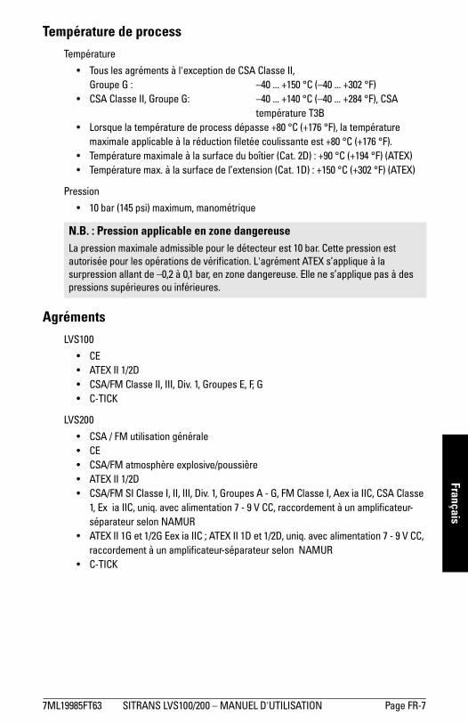
7ML19985FT63 SITRANS LVS100/200 � MANUEL D'UTILISATION Page FR-7
mm
mm
m
Français
Température de processTempérature
� Tous les agréments à l'exception de CSA Classe II, Groupe G : �40 ... +150 °C (�40 ... +302 °F)
� CSA Classe II, Groupe G: �40 ... +140 °C (�40 ... +284 °F), CSA température T3B
� Lorsque la température de process dépasse +80 °C (+176 °F), la température maximale applicable à la réduction filetée coulissante est +80 °C (+176 °F).
� Température maximale à la surface du boîtier (Cat. 2D) : +90 °C (+194 °F) (ATEX)� Température max. à la surface de l�extension (Cat. 1D) : +150 °C (+302 °F) (ATEX)
Pression
� 10 bar (145 psi) maximum, manométrique
AgrémentsLVS100
� CE� ATEX II 1/2D� CSA/FM Classe II, III, Div. 1, Groupes E, F, G� C-TICK
LVS200
� CSA / FM utilisation générale� CE� CSA/FM atmosphère explosive/poussière� ATEX II 1/2D� CSA/FM SI Classe I, II, III, Div. 1, Groupes A - G, FM Classe I, Aex ia IIC, CSA Classe
1, Ex ia IIC, uniq. avec alimentation 7 - 9 V CC, raccordement à un amplificateur-séparateur selon NAMUR
� ATEX II 1G et 1/2G Eex ia IIC ; ATEX II 1D et 1/2D, uniq. avec alimentation 7 - 9 V CC, raccordement à un amplificateur-séparateur selon NAMUR
� C-TICK
N.B. : Pression applicable en zone dangereuseLa pression maximale admissible pour le détecteur est 10 bar. Cette pression est autorisée pour les opérations de vérification. L'agrément ATEX s�applique à la surpression allant de �0,2 à 0,1 bar, en zone dangereuse. Elle ne s�applique pas à des pressions supérieures ou inférieures.

Page FR-8 SITRANS LVS100/200 � MANUEL D'UTILISATION 7ML19985FT63
mm
mm
m
Fran
çais
Installation
MontageN.B. :� L'installation doit être effectuée par un personnel qualifié et en accord avec les
dispositions réglementaires applicables.� Ne pas tordre, raccourcir ou rallonger les lames.� Lors de l'installation du raccord process, orienter les lames avec une clé plate de
50 mm (sans tourner le boîtier). Les lames vibrantes SITRANS LVS100/200 possèdent des marquages qui indiquent le point de commutation en montage vertical. L�'élément vibrant doit se trouver à la hauteur du point de commutation.
� En cas de pression, prévoir du ruban PTFE ou un produit d�étanchéité équivalent pour garantir le serrage approprié des raccords filetés coniques.
� Après le montage, veiller à ce que les entrées de câble soient orientées vers le bas pour éviter toute infiltration d�eau.
� Pour les détecteurs SITRANS LVS100/200 équipés de rallonge, prévoir un couple de serrage max. de 250 Nm au point de montage.
� Le couple de montage applicable au raccord fileté 1½" ne doit pas dépasser 80 Nm.
AVERTISSEMENTS : LVS100 et LVS200 :• Conformément à la Directive 97/ 23 / CE, ce produit est un
accessoire sous pression et ne doit pas être utilisé en tant que dispositif de sécurité.
• Une installation incorrecte peut provoquer une chute de pression dans le process.
• Pour installer les détecteurs en zone dangereuse veiller à respecter l'ensemble des réglementations applicables.
• Pour les installations ATEX, respecter la norme EN 50281-1-2 relative à l'utilisation en présence de poussières combustibles et températures. Avant d'ouvrir le couvercle de l'appareil veiller à ce qu'il ne présente pas de dépôts.
• Ne pas retirer le couvercle lorsque les circuits sont sous tension.• Installer le détecteur SITRANS LVS100/200 et veiller à ce les
frottements mécaniques ou les impacts n'engendrent pas d'étincelles entre le boîtier en aluminium et la cuve en acier.
LVS200 :• Installation en Zone 0 (électronique : NAMUR) : Le circuit courant
d'alimentation de sécurité intrinsèque doit être pourvu d'une isolation galvanique vers une zone NSI (non sécurité intrinsèque). Autrement, protéger l'appareil de la foudre (cf. norme EN 60079-14).
• Alimentation auxiliaire (électronique : NAMUR) : Le mode de protection par sécurité intrinsèque requiert la connexion à une alimentation certifiée de sécurité intrinsèque.
• Détecteurs LVS, versions tube/cable prolongateur avec électronique NAMUR, agréments pour zones dangereuses (gaz) : Le montage des détecteurs sur le couvercle de la cuve servant de séparation entre la Zone 0 (Cat. 1G) et la Zone 1 (Cat 2G), n'assure pas la protection efficace des détecteurs entre la Zone 0 et la Zone 1. Ce qui permet l'infiltration du gaz à travers le détecteur, de la Zone 0 à la Zone 1.
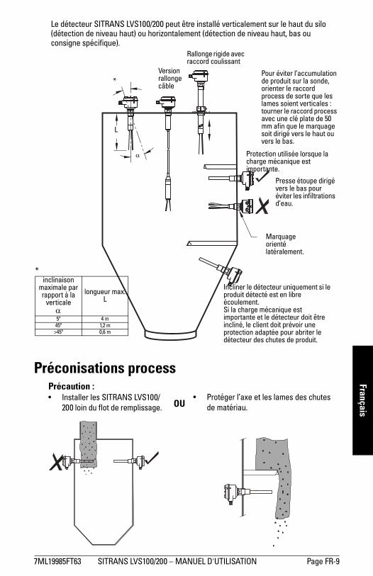
7ML19985FT63 SITRANS LVS100/200 � MANUEL D'UTILISATION Page FR-9
mm
mm
m
FrançaisLe détecteur SITRANS LVS100/200 peut être installé verticalement sur le haut du silo (détection de niveau haut) ou horizontalement (détection de niveau haut, bas ou consigne spécifique).
Préconisations process
Presse étoupe dirigé vers le bas pour éviter les infiltrations d�eau.
Protection utilisée lorsque la charge mécanique est importante.
Incliner le détecteur uniquement si le produit détecté est en libre écoulement. Si la charge mécanique est importante et le détecteur doit être incliné, le client doit prévoir une protection adaptée pour abriter le détecteur des chutes de produit.
*inclinaison
maximale par rapport à la
verticaleα
longueur max. L
5º 4 m45º 1,2 m
>45º 0,6 m
*
L
Marquage orienté latéralement.
α
Pour éviter l�accumulation de produit sur la sonde, orienter le raccord process de sorte que les lames soient verticales : tourner le raccord process avec une clé plate de 50 mm afin que le marquage soit dirigé vers le haut ou vers le bas.
Rallonge rigide avec raccord coulissant
Version rallonge câble
Précaution :� Installer les SITRANS LVS100/
200 loin du flot de remplissage.� Protéger l�axe et les lames des chutes
de matériau.OU

Page FR-10 SITRANS LVS100/200 � MANUEL D'UTILISATION 7ML19985FT63
mm
mm
m
Fran
çais
Dimensions - SITRANS LVS100
120 mm (4.72")
150 mm (5.91")
bride process fournie par le client
170 ... 4000 mm (6.69 ... 157") : rallonge rigide suivant spécifications du client
125 mm (4.92") : fourche standard
60 mm (2.36")
60 mm (2.36") 75 mm
(2.95")
marquage pour l�orientation des lames
Zone 21(Cat. 2)
Zone 20(Cat. 1)
réduction filetée [température max. +80°C (+176°F)]
fourche
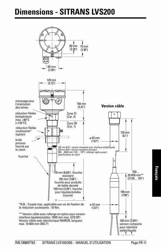
7ML19985FT63 SITRANS LVS100/200 � MANUEL D'UTILISATION Page FR-11
mm
mm
m
Français
Dimensions - SITRANS LVS200
120 mm (4.72")
150 mm (5.91")
bride process fournie par le client
165 mm (6.5") : version compacte pour interface solide/liquide230 mm (9.0") :version compacte standard300 ... 4000 mm (11.81 ... 157") : rallonge rigide suivant spécifications du client
170 mm (6,69") : fourche standard
195 mm (7.68") :fourche pour produits
de faible densité 100 mm (3.94") : fourche
pour liquides/solides (courte)
60 mm (2.36")
60 mm (2.36")
75 mm (2.95")
marquage pour l�orientation des lames
Zone 21(Cat. 2)
Zone 20(Cat. 1)
réduction filetée [température max. +80°C (+176°F)]réduction filetée coulissante* (option)
*N.B. : Couple max. applicable aux vis de fixation de la réduction coulissante : 10 Nm.
** Version câble avec rallonge en option pour version interface liquides/solides, 7000 mm max. (275.59")Version câble avec électronique NAMUR, longueur max. 10 000 mm (393.7")
fourche
100 mm (3.94") : version compacte pour interface solide/liquide
Version câble
195 mm (7.68")
700 ... 20 000 mm** (27.56 ... 787")
155 mm (6.1")
ø 42 mm (1.67")
ø 42 mm (1.67")

Page FR-12 SITRANS LVS100/200 � MANUEL D'UTILISATION 7ML19985FT63
mm
mm
m
Fran
çais
Câblage
Recommandations pour la connexion� Utiliser un fusible pour la sortie de signal (10 A max.).� Lorsque des charges inductives sont utilisées, protéger les contacts relais afin de
protéger le détecteur des pointes.
Précautions� Avant d'ouvrir le couvercle vérifier l'absence de dépôts de poussière sur le
SITRANS LVS100/200 et attendre que l'atmosphère environnante se stabilise.� La tension de secteur ne doit pas être supérieure à la tension maximale reportée
sur l�étiquette de l'instrument.� Pour éviter tout contact avec les pièces sous tension, chaque câble ne doit pas
comporter une section dénudée de plus de 8 mm.� Pour la même raison, la longueur des protections des têtes de câble ne doit pas
dépasser 8 mm.
AVERTISSEMENTS :• Avant d'ouvrir le détecteur SITRANS LVS100/200 couper l'alimentation.• Tous les câblages doivent être isolés pour 250 V CA minimum. • Un disjoncteur facilement accessible, servant de commutateur de
mise hors service doit se trouver à proximité de l’appareil.• Utiliser des conduits et des presse-étoupes adaptés aux zones
dangereuses. Utiliser un bouchon approprié pour fermer les raccords de conduit non utilisés.
• Respecter les normes et les dispositions réglementaires applicables localement.
N.B. :Exigences européennes� L'installation des détecteurs SITRANS LVS100/200 en zone dangereuse requiert
l'utilisation de presse-étoupes et/ou bouchons (fourniture client) certifiés ATEX 100a ; antidéflagrants. Respecter la plage de température minimale applicable : -40 ... +70°C (-40 ... +158°F). Respecter l�indice de protection minimal IP6x applicable suivant la norme européenne EN 60529. Respecter les consignes et les recommandations d�utilisation fournies dans la documentation du presse-étoupe.
� Respecter les recommandations stipulées dans la norme européenne EN 50281-1-2 concernant l�accumulation de poussière et la température.

7ML19985FT63 SITRANS LVS100/200 � MANUEL D'UTILISATION Page FR-13
mm
mm
m
Français
Tension universelle (relais DPDT)(LVS100)
Tension universelle (relais SPDT)(LVS200)
12345678
relais de sortie alarme
Réglage FSH/FSLréglage de la sensibilité
B = réglage usine, A = sensibilité réduite
CA : borne 1 : Lborne 2 : N19 ... 230 V CA, + 10 %, 50 ... 60 Hz, 8 VA
CC : borne 1 : +borne 2 : -19 ... 50 V CC, + 10 %, 2 W
AB
FSH
FSL
DEL
relais sortie alarme
Réglage FSH/FSL
réglage de la sensibilitéB = réglage usine, A = sensibilité réduite
CA : borne 1 : Lborne 2 : N19 ... 230 V CA, + 10 %, 50 ... 60 Hz, 8 VA
CC : borne 1 : +borne 2 : -
19 ... 55 V CC, + 10 %, 1.5 W
borne de mise à la terre (protection)
AB
FSH
FSL
DEL

Page FR-14 SITRANS LVS100/200 � MANUEL D'UTILISATION 7ML19985FT63
mm
mm
m
Fran
çais
Tension universelle (relais DPDT) 3 fils PNP(LVS200) (LVS200)
2 fils NAMUR IEC 60947-5-6 8/16 mA ou 4 - 20 mA(LVS200) (LVS200) (LVS200)
PE +L
-N
relais de sortie alarmePE + -
charge
CA : borne 1 : Lborne 2 : N19 ... 230 V CA, + 10 %, 50 ... 60 Hz, 18 VA
CC : borne 1 : +borne 2 : -19 ... 55 V CC, + 10 %, 2 W
CC : borne 1 : +borne 2 : -18 ... 50 V CC, + 10 %, 1.5 W
PE +L
-N PE + - PE + -
CA : borne 1 : Lborne 2 : N19 ... 230 V CA, + 10 %,
50 ... 60 Hz, 1.5 VACC : borne 1 : +
borne 2 : -19 ... 230 V CC, + 10 %, 1 W
environ 7 ... 9 V CC, sécurité intrinsèque(IEC 60947-5-6)
CC : borne 1 : +borne 2 : -12,5 ... 36 V CC, + 0 %

7ML19985FT63 SITRANS LVS100/200 � MANUEL D'UTILISATION Page FR-15
mm
mm
m
Français
SensibilitéLe réglage de la sensibilité intervient lorsque le produit détecté tend à former des dépôts. Le commutateur de sélection se positionne sur A pour diminuer la sensibilité de détection (réglage usine : position B).
Pour détecter une interface liquide/solide placer le commutateur en position B. Pour détecter un niveau haut, placer le commutateur en position A.
LVS100
LVS200
Réglage FSH/FSL ou réglage alarme haute/basse
réglage de la sensibilité :B = réglage usine A = sensibilité réduite
FSH
FSL
AB
Réglage FSH/FSL ou réglage alarme haute/basse (NAMUR)
réglage de la sensibilité :B = réglage usine A = sensibilité réduite
FSH
FSL
AB

Page FR-16 SITRANS LVS100/200 � MANUEL D'UTILISATION 7ML19985FT63
mm
mm
m
Fran
çais
Logique de commutationSonde découverte
Sortie signalModèle Sécurité-défaut bas Sécurité-défaut haut
LVS100
Relais DPDT
LVS200
Relais SPDT
LVS200
Relais DPDT
3 fils PNP
2 fils
8/16 mA I = 16 mA I = 8 mA
Témoin DEL sortie signal
Réglage alarme basse Réglage alarme haute
NAMUR IEC 60947-5-6
I < 1 mA I > 2,2 mA
Témoin DEL sortie signal
7 6 5 4 38 8 7 6 5 4 3
3 4 5 3 4 5
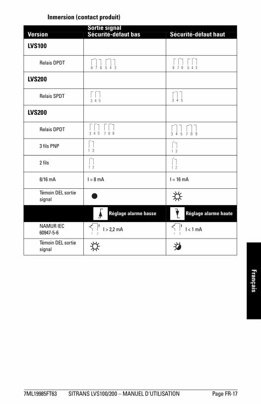
7ML19985FT63 SITRANS LVS100/200 � MANUEL D'UTILISATION Page FR-17
mm
mm
m
Français
Inmersion (contact produit)
Sortie signalVersion Sécurité-défaut bas Sécurité-défaut haut
LVS100
Relais DPDT
LVS200
Relais SPDT
LVS200
Relais DPDT
3 fils PNP
2 fils
8/16 mA I = 8 mA I = 16 mA
Témoin DEL sortie signal
Réglage alarme basse Réglage alarme haute
NAMUR IEC 60947-5-6
I > 2,2 mA I < 1 mA
Témoin DEL sortie signal
8 7 6 5 4 3 7 6 5 4 38
3 4 5 3 4 5
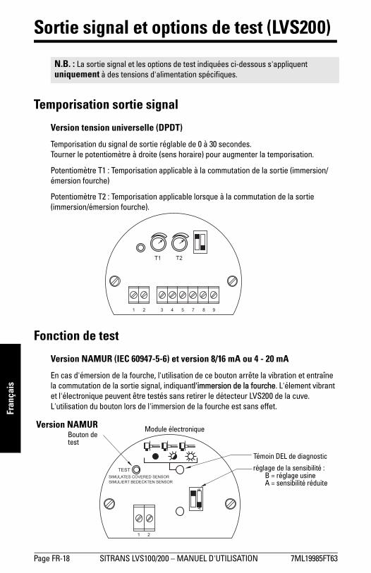
Page FR-18 SITRANS LVS100/200 � MANUEL D'UTILISATION 7ML19985FT63
mm
mm
m
Fran
çais
Sortie signal et options de test (LVS200)
Temporisation sortie signal
Version tension universelle (DPDT)
Temporisation du signal de sortie réglable de 0 à 30 secondes. Tourner le potentiomètre à droite (sens horaire) pour augmenter la temporisation.
Potentiomètre T1 : Temporisation applicable à la commutation de la sortie (immersion/émersion fourche)
Potentiomètre T2 : Temporisation applicable lorsque à la commutation de la sortie (immersion/émersion fourche).
Fonction de test
Version NAMUR (IEC 60947-5-6) et version 8/16 mA ou 4 - 20 mA
En cas d'émersion de la fourche, l'utilisation de ce bouton arrête la vibration et entraîne la commutation de la sortie signal, indiquantl'immersion de la fourche. L'élement vibrant et l'électronique peuvent être testés sans retirer le détecteur LVS200 de la cuve. L'utilisation du bouton lors de l'immersion de la fourche est sans effet.
N.B. : La sortie signal et les options de test indiquées ci-dessous s'appliquent uniquement à des tensions d'alimentation spécifiques.
Bouton de test
Module électronique
Témoin DEL de diagnostic
Version NAMUR
réglage de la sensibilité :B = réglage usine A = sensibilité réduite
AB
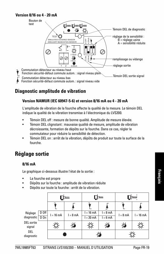
7ML19985FT63 SITRANS LVS100/200 � MANUEL D'UTILISATION Page FR-19
mm
mm
m
Français
Diagnostic amplitude de vibration
Version NAMUR (IEC 60947-5-6) et version 8/16 mA ou 4 - 20 mA
L'amplitude de vibration de la fourche affecte la qualité de la mesure. Le témoin DEL indique la qualité de la vibration transmise à l'électronique du LVS200.
� Témoin DEL off : mesure de bonne qualité. Amplitude de mesure élevée.� Témoin DEL clignotant : mauvaise qualité de mesure, amplitude de vibration
décroissante, formation de dépôts sur la fourche. Dans ce cas, régler le commutateur pour réduire la sensibilité de détection.
� Témoin DEL on : arrêt de la vibration, dépôts de produit sur toute la surface de la fourche.
Réglage sortie
8/16 mA
Le graphique ci-dessous illustre l'état de la sortie :
� La fourche est propre� Dépôts sur la fourche : amplitude de vibration réduite� Dépôts sur toute la fourche : arrêt de la vibration.
Réglage diagnostic
D OffI = 16 mA I = 8 mA
I = 16 mA I = 8 mAI = 8 mA I = 16 mA
D On I = 20 mA I = 6 mA
DEL sortie signal
DEL diagnostic
Version 8/16 ou 4 - 20 mABouton de test
Témoin DEL de diagnostic
réglage de la sensibilité :B = réglage usine A = sensibilité réduite
BA
remplissage ou vidange
réglage sortie
Témoin DEL sortie signal
Commutation détecteur au niveau hautFonction sécurité-défaut commute autom. : signal niveau pleinCommutation détecteur au niveau basFonction sécurité-défaut commute autom. : signal niveau vide
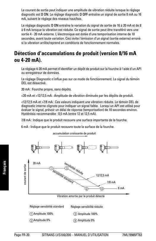
Page FR-20 SITRANS LVS100/200 � MANUEL D'UTILISATION 7ML19985FT63
mm
mm
m
Fran
çais
Le courant de sortie peut indiquer une amplitude de vibration réduite lorsque le réglage diagnostic est D ON. Le réglage diagnostic D OFF entraîne un signal de sortie 8 mA ou 16 mA, suivant le réglage des niveaux haut/bas.
Le réglage diagnostic D ON entraîne la variation du signal de sortie de 16 à 20 mA et de 8 à 6 mA lorsque la vibration est réduite. Ce signal de sortie peut être transféré vers une sortie 4 - 20 mA externe. L'électronique est dotée d'une temporisation interne de 10 secondes, avant toute variation. Ceci évite l'émission d'un signal (sortie externe) erroné si la vibration arrête/reprend en conditions de fonctionnement normales.
Détection d'accumulations de produit (version 8/16 mA ou 4-20 mA).
Le réglage 4-20 mA permet d'identifier un dépôt de produit sur la fourche à l'aide d'un API ou enregistreur de données.
Le réglage Diagnostic n'influe pas sur ce mode de fonctionnement. Le signal du témoin DEL est désactivé.
20 mA : Fourche propre, sans dépôts.
<20 mA et >12/12,5 mA : Amplitude de vibration diminuée par les dépôts de produit.
<12/12,5 mA et >7/8 mA : Ces valeurs indiquent une vibration réduite. Le témoin DEL de diagnostic interne clignote pour indiquer un signal faible. Lorsqu'un API est utilisé pour évaluer le signal, prévoir un délai de réponse (temporisation) de 10 secondes environ. Hystérésis recommandée : 0,5 mA (entre 12 et 12,5 mA).
7/8 mA : Indique que le produit recouvre une surface importante de la fourche.
6 mA : Indique que le produit recouvre toute la surface de la fourche.
accumulation croissante de produit
Amplitude 100%
Amplitude 0%
Amplitude 100%
Amplitude 0%
Réglage sensibilité standard Réglage sensibilité réduite
6 mA
7/8 mA
12/12,5 mA
20 mA
cour
ant d
e so
rtie
sensibilité standard
sensibilité réduite
Vibration amortie par le produit détecté

7ML19985FT63 SITRANS LVS100/200 � MANUEL D'UTILISATION Page FR-21
mm
mm
m
Français
Maintenance
Utilisés en conditions de fonctionnement normales, les SITRANS LVS100/200 ne requierent pas de maintenance ou de nettoyage. En conditions de fonctionnement extrêmes il peut être nécessaire de nettoyer les lames régulièrement. Utiliser une brosse pour éliminer toute accumulation de produit. Veiller à ne pas tordre les lames.
Réparation de l'appareil et limite de responsabilitéToute modification ou réparation doit être effectuée par un personnel qualifié. Respecter les consignes de sécurité. Remarques importantes :
� Toute modification ou réparation de l'instrument sera effectuée sous la responsabilité de l'utilisateur.
� Tous les composants doivent être fournis par Siemens Milltronics Process Instruments Inc.
� Réparer uniquement les composants défectueux.� Ne pas reutiliser des composants défectueux.

Page FR-22 SITRANS LVS100/200 � MANUEL D'UTILISATION 7ML19985FT63
mm
mm
m
Fran
çais
SITRANS LVS200 version avec tube prolongateur
MontageOutils conseillés :
1. Ouvrir le couvercle et retirer l'électronique.2. Insérer le câble du détecteur dans le tube de 1" fourni par le client et le boîtier.3. Monter l'ensemble fourche, tube prolongateur et boîtier avec la clé plate 36 mm.
Appliquer une pâte adaptée sur les filetages du tube prolongateur pour assurer l'étanchéité.
4. Aligner les marquages sur la fourche et sur les lames tel qu'illustré dans le schéma page page 12. (Le raccord process comporte un marquage permettant d'orienter les lames et de positionner la fourche verticalement.)
5. Raccourcir le câble du détecteur pour obtenir une longueur libre de 150 mm (5,9"). 6. Raccourcir le câble de prise de terre pour obtenir une longueur libre de 220 mm
(8,7"). 7. Préparer le câble du détecteur tel qu'illustré ci-dessus. Retirer 8 mm (max.) de
chaque câble.
� tournevis plat moyen Phillips ou 6 à 8 mm (¼�) � pince à sertir
� tournevis plat 3 mm (1/8�) � clé plate 36 mm
� coupe-câbles � clé à tubes
� pinces à dénuder
N.B. : Ne pas tourner l'ensemble fourche. Veiller à ne pas tordre l'ensemble fourche durant le montage.
boîtier fourniture client tube prolongateur
ensemble fourche
câble de prise de terre (vert/jaune)220 mm
(8.7")
150 mm (5.9")
8 mm max.18 mm
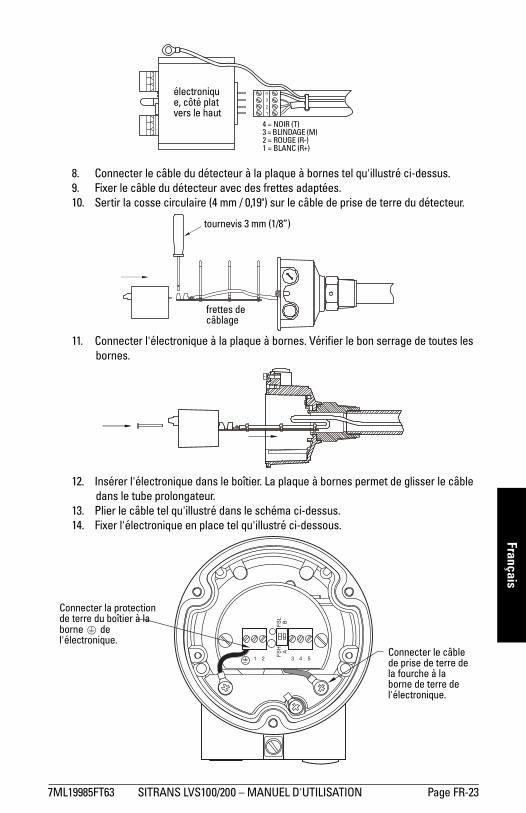
7ML19985FT63 SITRANS LVS100/200 � MANUEL D'UTILISATION Page FR-23
mm
mm
m
Français
8. Connecter le câble du détecteur à la plaque à bornes tel qu'illustré ci-dessus. 9. Fixer le câble du détecteur avec des frettes adaptées.10. Sertir la cosse circulaire (4 mm / 0,19") sur le câble de prise de terre du détecteur.
11. Connecter l'électronique à la plaque à bornes. Vérifier le bon serrage de toutes les bornes.
12. Insérer l'électronique dans le boîtier. La plaque à bornes permet de glisser le câble dans le tube prolongateur.
13. Plier le câble tel qu'illustré dans le schéma ci-dessus. 14. Fixer l'électronique en place tel qu'illustré ci-dessous.
électronique, côté plat vers le haut
4 = NOIR (T) 3 = BLINDAGE (M) 2 = ROUGE (R-) 1 = BLANC (R+)
tournevis 3 mm (1/8�)
frettes de câblage
Connecter la protection de terre du boîtier à la borne de l'électronique.
Connecter le câble de prise de terre de la fourche à la borne de terre de l'électronique.

Page FR-24 SITRANS LVS100/200 � MANUEL D'UTILISATION 7ML19985FT63
mm
mm
m
Fran
çais
Schéma d'assemblage
½” NPT
M20x1.5
1 ½” NPT
1 ½" BSPT
1" NPT
G 1"
co
module électronique
plaque à bornes
câble du détecteur
ensembleboîtier
raccord process
marquage pour l�orientation des lames
raccord process fileté 1 ½� NPT (cône) ouR 1 ½� (BSPT)
filetage G1� ou 1" NPT(appliquer un produitd'étanchéité adapté)
fourche
ensemble fourche
filetage G1� ou 1" NPT(appliquer un produitd'étanchéité adapté)
Tube 1", épaisseur 40mm (diamètre intérieurmin. 25,4 mm (fourni et
installé par le client)
X = Long. 255 mm (10")
min. 18 mm (0.75")
min. 18 mm (0.75")
SW 36
N.B. : Longueur minimale en prise du filetage : 7 mm (0,27")
138 mm environ
(5,4")
L = 300 à 3800 mm (11,8 à 149,6")
170 mm(6.7")
raccord process fileté
entrées de câble
Filetage tube, 1" NPT

IQ300IX.fm Page 5 Tuesday, October 2, 2001 1:43 PM
*7ml19985FT63*Rev. 3.0
www.siemens.com/processautomation
Siemens Milltronics Process Instruments Inc.1954Technology Drive, P.O. Box 4225Peterborough, ON, Canada K9J 7B1Tel: (705) 745-2431 Fax: (705) 741-0466Email: [email protected]
Siemens Milltronics Process Instruments Inc. 2009Subject to change without prior notice
Printed in Canada