english owner’s manual
TRANSCRIPT

P3200IE
ENGlish
OWNER’SMANUAL
For MAINTENANCE AND SAFETY

WARNINGOperating, servicing and maintaining this equipment can expose you to chemicals including engine exhaust, carbon monoxides, soots, mineral
oils, and lead which are known to cause cancer and birth defects or other reproductive harm. To minimize exposure, avoid breathing exhaust, do not idle the engine except as necessary. Service and operate your equipment in a well-ventilated area and wear gloves or wash hands frequently when
servicing your equipment.
For more information go to www.P65Warnings.ca.gov.
! WARNINGRead, understand, and follow all of the instructions and safety
precautions in this manual and on all product labels.
Failure to follow the safety precautionscould result in serious injury or death.
!

POLARIS® and POLARIS POWER® are trademarks of POLARIS IndustriesInc.
Copyright 2019 Polaris Industries Inc. All information contained within thispublication is based on the latest product information at the time ofpublication. Due to constant improvements in the design and quality ofproduction components, some minor discrepancies may result between theactual product and the information presented in this publication. Depictionsand/or procedures in this publication are intended for reference use only. Noliability can be accepted for omissions or inaccuracies. Any reprinting orreuse of the depictions and/or procedures contained within, whether whole orin part, is expressly prohibited.
The original instructions for this product are in English. Other languages areprovided as translations of the original instructions.
Printed in China9931063 Rev 03

Designed in our labs, put to the test in yours.
Power for everything, for everyone. We've designed Polaris Power® with thatsimple principle in mind. From long weekend camping trips and tailgating toconstruction sites and power while you wait out the storm, we've got youcovered.
Our line of generators are built for it all. No detail too small, no spec overlooked.We've redefined the definition of limits, so you can keep redefining yours.
• P2000i Inverter Generator• P3200iE Inverter Generator• P5500 Open Frame Generator• P6500 Open Frame Generator
Your owner’s manual contains instructions for minor maintenance, butinformation about major repairs is outlined in the POLARIS Service Manual andcan be performed by a factory certified Master Service Dealer® (MSD)Technician.
Your POLARIS dealer knows your generator best and is interested in your totalsatisfaction. Your POLARIS dealership can perform all of your service needsduring, and after, the warranty period.
3
WELCOME

4
WELCOME

Introduction . . . . . . . . . . . . . . . . . . . . 7Safety . . . . . . . . . . . . . . . . . . . . . . 11Features and Controls . . . . . . . . . . . . . . 27Assembly . . . . . . . . . . . . . . . . . . . . 37First Use Instructions . . . . . . . . . . . . . . . 43Operation . . . . . . . . . . . . . . . . . . . . 49Emission Control Systems . . . . . . . . . . . . . 63Maintenance . . . . . . . . . . . . . . . . . . 65Specifications . . . . . . . . . . . . . . . . . . 93POLARIS Products . . . . . . . . . . . . . . . . 95Troubleshooting . . . . . . . . . . . . . . . . . 97Warranty . . . . . . . . . . . . . . . . . . . . 101Maintenance Log . . . . . . . . . . . . . . . . 111
5

6

INTRODUCTIONOVERVIEWFor a safe and enjoyable operation of your new generator, please read theentirety of this owner’s manual. If you should need additional assistance withgenerator operation or maintenance, please see your POLARIS dealer or othercertified service technician.
After reading this manual in its entirety, store in a convenient location for futurereference.
NOTICEYou must complete the Warranty Registration Form included with your
generator and forward it to POLARIS within 10 days of purchase. Warrantycoverage will not be active unless your generator is registered.
INTENDED USEThe Polaris Power® Generator is intended to supply power. Such items include,but are not limited to:
• Furnace fans• Sump pumps• Dishwashers• Hotplates / stoves• Washing machines• Garage door openers• Water heaters• Refrigerators• Campers / RVs• Circular saws
Items that use more than the recommended amount of combined powerconsumption should not be connected to this generator.
7
INTRODUCTION

SAFETY SYMBOLS AND SIGNALWORDSThe following signal words and symbols appear throughout this manual and onyour generator. Your safety is involved when these words and symbols are used.Become familiar with their meanings before reading the manual.
DANGERDANGER indicates a hazardous situation which, if not avoided, WILL result in
death or serious injury.
WARNINGWARNING indicates a hazardous situation which, if not avoided, COULD result
in death or serious injury.
CAUTIONCAUTION indicates a hazardous situation which, if not avoided, COULD result
in minor to moderate injury.
NOTICE
NOTICE provides key information by clarifying instructions.
IMPORTANTIMPORTANT provides key reminders during disassembly, assembly, and
inspection of components.
The Prohibition Safety Sign indicates an action NOT to take inorder to avoid a hazard.
The Mandatory Action Sign indicates an action that NEEDS tobe taken to avoid a hazard.
8
INTRODUCTION

GENERATOR IDENTIFICATION NUMBERSThe generator serial numberq and engine serial numberw can be foundstamped inside the maintenance cover beside the air box.
Record your generator’s serial numbers and purchase date in the spacesprovided.
Model Number P3200iE
Generator Serial Number
Engine Serial Number
Purchase Date
9
INTRODUCTION

10

SAFETYSAFETY WARNINGS
WARNINGFailure to follow recommended precautions and procedures could result insevere injury or death. Always follow all safety warnings on the product, andfollow all operation, inspection, and maintenance procedures outlined in this
manual.
Understand and follow all inspection and maintenance procedures outlined inthis manual. Following these procedures is essential for the generator to remainin safe operating condition.
If the generator is not in use for an extended period of time, turn the ignitionswitch and fuel valve switch to the OFF position.
WARNINGIt is the responsibility of the owner to ensure that all users of this generator are
fully informed of the safety and operating information prior to use.
OPERATOR SAFETYWARNING
Operating the generator with worn, damaged, or malfunctioning componentscould result in serious injury or death. Never start the engine without checking
all of the generator components to be sure of proper operation.
Please take the following precautions, which are essential for proper and safeoperation:
• Read and understand all of the safety and operating information in thismanual and on all warning and instruction labels before using the generator.Use the generator only as described in this manual and on the product.
• Know how to stop the generator quickly in case of emergency, see page 19for information on stopping the unit quickly.
• Keep children, pets, and bystanders at a safe distance from the generator.• Review and understand the use of all generator controls, output receptacles,and connections.
• Be sure that anyone who operates the generator receives proper instructionand reads this manual completely. Do not let children operate the generator.
• Use the generator only for intended purposes.
11
SAFETY
• Turn off the generator immediately if the unit begins to operate abnormally.After the generator has cooled, disconnect the generator and take to yourauthorized Polaris dealer.
• While operating the generator, if you experience a headache, fatigue, nausea/ vomiting, confusion, or seizures, immediately get to fresh air. Do not delayand do not attempt to shut down the unit.
OPERATING WITHOUT INSTRUCTIONWARNING
Operating this generator without proper instruction increases the risk of severeinjury or death.
The operator must understand how to operate thegenerator safely in proper conditions andenvironments.
All operators must read and understand the owner'smanual and all warning and instruction labels beforeoperating the generator.
FAILURE TO INSPECT BEFORE OPERATINGWARNING
Failure to inspect and verify that the generator is in safe operating conditionbefore operating increases the risk of an accident resulting in severe injury ordeath.Always perform the pre-operation inspection before each use of your generatorto make sure it's in safe operating condition.Always follow the inspection and maintenance procedures and schedulesdescribed in this owner’s manual.
12
SAFETY

USING ALCOHOL OR DRUGS
WARNINGNever consume alcohol or drugs before or while
operating this generator.Operating this generator after consuming alcohol ordrugs could adversely affect operator judgment.
CARBON MONOXIDE SAFETYWARNING
Generator exhaust contains Carbon Monoxide (CO) vapors. Exposure toCarbon Monoxide by people or pets can result in SEVERE INJURYor DEATH.ALWAYS operate generator according to all warning and instruction labels and
this manual.
• This portable generator runs on gasoline. The generator exhaust vaporcontains carbon monoxide (CO).
• Carbon monoxide is odorless. You cannot smell it.• Carbon monoxide is colorless. You cannot see it.• The generator is for outdoor use only. Never run the generator in an enclosedarea. Exhaust contains poisonous carbon monoxide vapor that can causeloss of consciousness or death. Operate the generator in an open, and wellventilated area.
• Do not use the generator indoors in garages, basements, crawl spaces,sheds, portable buildings, or similar areas even if doors and windows areopen or if ventilating fans are used to circulate air.
• Do not use the generator near windows, doors, vents or any other buildingopenings even if they are closed. Poor seals on a door, as one example,could still permit high levels of carbon monoxide to infiltrate the living area of ahome.
• Be sure to install approved carbon monoxide detectors in your home thathave battery back-up systems that will continue to detect the presence ofcarbon monoxide during electric-power outages. Test these devices andreplace batteries as recommended by their respective manufacturers.
IMPORTANTIf you experience a headache, fatigue, nausea / vomiting, confusion, or
seizures, immediately get to fresh air and away from the unit. Do not delay forany reason.
13
SAFETY

ELECTRICAL SAFETYDANGER
This generator produces high voltage electricity sufficient to cause death byelectrocution.
• The generator produces enough electric power to cause serious shock orelectrocution if misused.
• Always connect the generator to a suitable ground circuit.• When servicing the generator, disconnect the spark plug wire and place itwhere it cannot contact the plug. Turn the engine switch to the OFF position.
• Do not check for a spark with the plug removed. Use only approved sparkplug testers.
• Using a generator or electrical appliance in wet conditions, such as rain orsnow, or near a pool or sprinkler system, or when your hands are wet, couldresult in severe shock or electrocution. Keep the generator dry and away fromall sources of moisture.
• If the generator is stored outdoors, unprotected from the weather, check allelectrical components on the control panel before each use. Moisture or icecan cause a malfunction or short circuit in electrical components that couldresult in electrocution.
• Do not connect the generator to a building’s electrical system unless anisolation switch has been installed that meets applicable electrical codes andregulations.
• To avoid overloading the generator, ensure load is kept within the rated powerrange stated on the generator. Overloading will damage the unit and / orshorten its operating lifespan.
14
SAFETY

EXTENSION CORD USERead the manufacturer starting and running wattage details and operatinginstructions for the device(s) and appliance(s) that will be used. Often thisinformation can be found in the owner's manual or on specification decals on thedevice or appliance.
CHOOSING A PROPER EXTENSION CORDPolaris recommends using only U.L. (Underwriters Laboratories, Inc.) approvedextension cords labeled with the use, size, and wattage rating.
Only use heavy-duty extension cords with a three-prong (grounded) plug foryour safety.
Decide on what length extension cord is required as cord length determines theextension cord gauge. Remember, as the cord gets longer, the current capacityof the cord decreases.
Never use an extension cord outdoors that is designated as “indoor use only”.
EXTENSION CORD SAFETYYour generator is equipped with optional cord holder hooksq for storage of anextension cord. See for assembly instructions.
Store all extension cords indoors whennot in use. Outdoor conditions candeteriorate a cord over time.
Before plugging an extension cord orpower cord into the generator, checkthe cord for signs of damage.
CAUTIONDo not store an extension cord on the generator while the generator is in use.Hot surfaces from the engine could result in damage to the cord. Wait until
generator has been turned off and cooled before storing an extension cord onthe hooks.
IMPORTANTThe cord will still conduct electricity until it is unplugged from the outlet.
15
SAFETY

FIRE SAFETYWARNING
Gasoline is extremely flammable and is explosive under certain conditions. Donot smoke or allow flames or sparks where generator is refueled or wheregasoline is stored. Refuel in a well-ventilated area with the engine OFF.
CAUTIONGenerator exhaust system gets hot enough to ignite some materials and burn
skin if touched.
• Keep the generator at least 3 feet (1 m) away from buildings, otherequipment, and combustible materials during operation.
• Do not enclose the generator in any structure.• Keep children and pets away from generator.• Exhaust system components are very hot during and after use. Hotcomponents can cause burns and fire. Do not touch the hot exhaust systemcomponents. Always keep combustible materials away from the exhaustsystem.
• Ensure that any spilled fuel is properly wiped up prior to using the generatoras fuel vapors are flammable.
EXPOSURE TO EXHAUSTWARNING
Exhaust fumes from your generator are poisonous and can cause loss ofconsciousness or death in a short time. Never start the generator or let it run in
an enclosed area. Only operate this generator while outdoors.
16
SAFETY

HOT EXHAUST SYSTEMSWARNING
Exhaust system components are very hot during and after use of the machine.Hot components can cause burns and fire. Do not touch hot exhaust systemcomponents. Always keep combustible materials away from the exhaust
system.Use caution when operating near tall grass, especially dry grass. Always
inspect the exterior of the generator and areas near the exhaust system beforeand after use. Promptly remove any grass, debris, or foreign matter clinging to
the generator. Pay particular attention to the exhaust system area.
NOTICEDo not apply the storage cover to the generator while the engine components
are still hot. Wait until generator has sufficiently cooled before covering.
17
SAFETY

RUNNING GENERATORS IN PARALLELWARNING
Only connect in parallel with a Polaris Power P3200iE or P2000i generator withan approved parallel cable (sold separately). Attempting to connect otherbrands or models will void your warranty and could cause severe injury.
EQUIPMENT MODIFICATIONSYour POLARIS generator is designed to provide safe operation when used asdirected. Modifications to your generator may negatively impact generatorstability. Failure of critical machine components may result from operation withany modifications, especially those that increase power.
Do not install any non-POLARIS-approved accessory or modify the generatorfor the purpose of increasing power output. Any modifications or installation ofnon-POLARIS-approved accessories could create a substantial safety hazardand increase the risk of bodily injury.
Modifying the generator by adding or removing any parts, components, or anymodifications not approved by Polaris may void the warranty. Such modificationsmay make the generator unsafe to operate and could result in severe injury tooperators and bystanders, as well as damage to the generator. Somemodifications may not be legal in your area. If in doubt, contact your authorizedPOLARIS dealer.
NOTICEFor more information about safety, call POLARIS at 1-800-342-3764.
18
SAFETY

HANDLING GASOLINEWARNING
Gasoline is highly flammable and gasoline vapor is explosive under certainconditions. Always use caution when handling gasoline.
• If the generator has been in operation, allow engine to cool completely beforerefueling.
• Always store gasoline in an approved container.• Always refuel outdoors or in a well-ventilated area away from any combustiblematerials.
• Do not smoke or allow open flames or sparks in or near the area whererefueling is performed or where gasoline is stored.
• Never permit children to handle gasoline.• Never refuel around bystanders, pets, and flammable objects.• Loosen the fuel cap slowly to relieve pressure in the tank.• Take care not to overfull or spill any fuel on the generator or muffler whenrefueling.
• If gasoline spills on skin or clothing, immediately wash it off with soap andwater and change clothing.
• Do not use the generator if you observe leaking gasoline. Have the generatorserviced immediately and before using it again.
• When operating or transporting the generator, be sure it is kept upright. If ittilts, fuel may leak. Be sure the fuel tank cap is tightened when transportingthe generator.
• Do not refuel using gas station pumps.• Remove fuel from the generator before transporting in a vehicle.
WARNINGAlways operate generator on level surface. If the generator is tilted, fuel mayspill or the generator may tip over, causing hazardous conditions. Do notswallow gasoline, inhale gasoline vapors, or spill gasoline. If you swallow
gasoline, inhale more than a few breaths of gasoline vapor, or splash gasolinein your eyes, see a physician immediately. If gasoline spills on skin or clothing,
immediately wash it off with soap and water and change clothing.
19
SAFETY
OPERATION RULES• Perform all Pre-Operation Inspection activities as shown on page 47 of thismanual. Inspect and tighten all parts before each use. Ensure the generatordoes not have any damaged, loose, or missing parts before use. All defectsshould be corrected before use. Do not operate the generator if it has beendropped or damaged until all defective parts have been repaired.
• Do not place any flammable materials near the generator.• Never start the generator or let it run in an enclosed area. Exhaust vapors arepoisonous and can cause loss of consciousness or death in a short time.Keep the generator away from buildings and other equipment duringoperation.
• Do not operate the generator in exposed locations where it will be subjectedto wet conditions.
• Do not touch the generator with wet hands, as this may cause severe electricshocks.
• Do not pour water directly over the generator or wash it.• Do not use or store the generator in the rain or snow.• Do not cover the generator when in use.• Always operate the generator on a firm, flat, and level surface, as thegenerator will vibrate on an irregular surface.
• If the generator is tilted, fuel may spill or the generator may tip over, causing ahazardous situation. Lock the wheels before using.
• Do not connect the generator to another power supply source.• The engine becomes extremely hot during and immediately after it has beenin use. Be careful not to touch any parts of the hot engine, especially themuffler or muffler cover, or serious burns may result.
• Do not connect external equipment to the generator before starting theengine.
• Do not use for life support, or life sustaining systems.
20
SAFETY

NOISE LEVELThe following noise chart lists average decibel levels for everyday sounds andappliances.
DANGERLEVEL
SOUND DECIBELLEVEL
PERMISSIBLEEXPOSURE TIME
SAFETYRECOMMENDA-TION
PainfulImpulseNoise
Fireworks (3 ft) /Shotgun Blast
150 dBP Not safe for anyperiod of time.
Avoid exposure. Notsafe for any period oftime.
Firearms 140 dBP Not safe for anyperiod of time.
PainfulSteady Noise
Jackhammer 130 dB(A) Not safe for anyperiod of time.
Jet Plane Takeoff/ Siren
120 dB(A) Not safe for anyperiod of time.
ExtremelyLoud
MP3 Player MaxOutput / RockConcert
112 dB(A) ~ 1 minute Wear earplugs orearmuffs.
Leaf Blower /Snow Blower
106 dB(A) > 4 minutes
Hair Dryer /Blender
94 dB(A) 1 hour
Very Loud Passingmotorcycle / GasLawn Mower
91 dB(A) 2 hours
Loud Busy Traffic /Vacuum Cleaner
85 dB(A) 8 hours No protectionrequired.
Moderate Generator /GroupConversation
70 dB(A) Unlimited
Dishwasher /Clothes Dryer
60 dB(A) Unlimited
Moderate Rainfall 50 dB(A) Unlimited
Raindrop / QuietRoom
40 dB(A) Unlimited
Faint Whispering 30 dB(A) Unlimited
21
SAFETY

HEARING PROTECTIONEarmuffs are worn over the ears. They must completely surround the ear and fitsnugly to reduce sound. Quality earmuffs, worn properly, can block up to 30decibels of noise.
Earplugs are inserted into the ear to completely block the ear canal. Qualityearplugs can reduce noise by up to 30 decibels.
22
SAFETY

SAFETY LABELS AND LOCATIONSWarning labels have been placed on the generator for your protection. Read andfollow the instructions on each label carefully. If any of the labels shown in thismanual differ from the labels on your generator, always read and follow theinstructions of the labels on the generator.
If an informational or graphic label becomes illegible or comes off, contact yourPOLARIS dealer to purchase a replacement. Replacement safety labels areprovided by POLARIS at no charge. The part number is printed on the label.
q General Warningw Carbon Monoxide Danger
e Hot Exhaust Caution
23
SAFETY

GENERALWARNINGThe general warning is located on the top side of the generator near the fuelvolume indicator.
WARNING
Improper generator use can result in SEVERE INJURYor DEATH. Read theowner’s manual. Follow all instructions and warnings.
Gasoline is flammable and explosive. Severe burnscan result.ALWAYS stop the engine and let cool down beforerefueling.ALWAYS check for fuel leaks and wipe up any spills.ALWAYS turn the fuel to OFF when not in use.NEVER handle gasoline indoors. NEVER overfill thefuel tank.
Generator exhaust contains poisonous CarbonMonoxide (CO) vapors.ALWAYS operate in a well-ventilated area.NEVER operate in a home, garage, enclosed area ornear windows, doors, or people.NEVER operate near flammable objects.
Electrocution can result from using generator in rain,snow, near water, with wet hands, or with improperconnections.ALWAYS keep generator and surrounding area dry.NEVER connect generator to any building withoutelectrical-isolation protection that meets applicablecodes and regulations.
24
SAFETY

CARBON MONOXIDE WARNINGThe carbon monoxide warning label is located on the top side of the generatornear the fuel level indicator.
DANGERUsing a generator indoors CAN KILL YOU IN MINUTES.
Generator exhaust contains carbon monoxide. This is a poison you cannot seeor smell.
NEVER use inside a home or garage. EVEN IFdoors and windows are open.
Only use OUTSIDE and far away from windows,doors, and vents.
HOT EXHAUST CAUTIONThe hot exhaust caution is located on the top side of the gas tank near the fuelvolume indicator.
CAUTION
Contacting a hot exhaust system can cause seriousburns. Do not touch if generator is or has been
running.
25
SAFETY

26

FEATURES AND CONTROLSOVERVIEW
27
FEATURES AND CONTROLS

COMPONENT DESCRIPTION
q Fuel Gauge Provides indication of fuel level.
w Control Panel Contains the switches, buttons, indicator panel,and receptacles for proper operation of thegenerator.
e Air Intake Provides air to cool the engine.
r Fuel Tank Cap Provides access to the fuel tank.
t Starter Grip Causes the recoil starter to crank the enginewhen pulled.
y Engine Oil ServiceDoor
Provides access to oil tank and dipstick.
u Folding Handle Allows for easier carrying and transport.
i Rear Handle Used combination with wheels to pull generatoracross flat surface.
o Air Exhaust Dispels exhaust air from cooling the engine.
a Muffler Reduces noise and emissions from enginecombustion.
s Cord Hooks Allows for storage of extension cords whengenerator is not in use.
d Maintenance Cover Provides access to inner components for routinemaintenance and repair.
fWheels Used in combination with folding handle to rollgenerator across flat surface.
28
FEATURES AND CONTROLS

CONTROL PANELSWITCHES AND BUTTONS
q Engine Switchw Choke Lever (if equipped)e SMART Throttle Switchr Fuel Valve Switch
t Parallel Sockety Overload Reset Buttonu Indicator Panel
29
FEATURES AND CONTROLS
RECEPTACLES
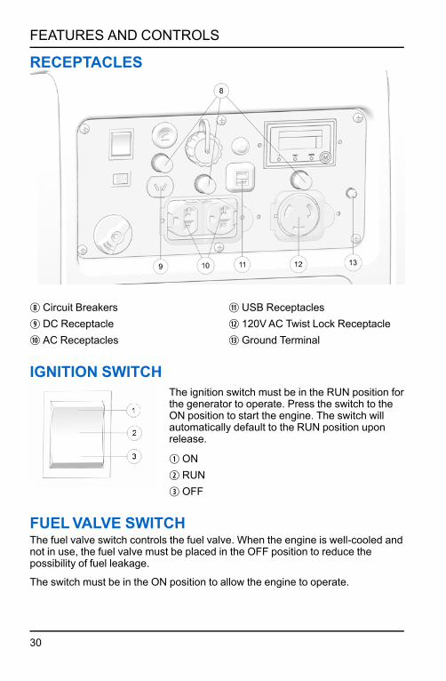
i Circuit Breakerso DC Receptaclea AC Receptacles
s USB Receptaclesd 120VAC Twist Lock Receptaclef Ground Terminal
IGNITION SWITCHThe ignition switch must be in the RUN position forthe generator to operate. Press the switch to theON position to start the engine. The switch willautomatically default to the RUN position uponrelease.
q ONw RUNe OFF
FUELVALVE SWITCHThe fuel valve switch controls the fuel valve. When the engine is well-cooled andnot in use, the fuel valve must be placed in the OFF position to reduce thepossibility of fuel leakage.
The switch must be in the ON position to allow the engine to operate.
30
FEATURES AND CONTROLS

q ON: opens the fuel valve.
w OFF: closes the fuel valve.
SMART THROTTLE SWITCHPress SMART throttle switch to ONposition to automatically reducesengine speed when loads are shut off ordisconnected. The engine will return tothe proper speed when appliances arein use or reconnected.
Press the SMART throttle switch to the OFF position to reduce voltage changeswhen high electrical loads are simultaneously connected or when using the DCoutput.
OVERLOAD RESET BUTTONThe overload reset buttonq is used in the case of sudden engine shutdownresulting from prolonged engine overload. Should the generator overload, ACpower will be cut off but the engine will stay running. Correct the overloadcondition and then press the overload reset switch on the front panel. AC powerwill be restored immediately.
31
FEATURES AND CONTROLS

In the case of engine overload:
1. Disconnect all electrical appliances.
2. Hold reset button for 1 second toreset the engine.
3. If overload indicator light has turnedoff and output light has re-illuminated, reconnect electricalappliances.
4. If overload indicator light is stillilluminated, set power switch to OFFand check generator.
IMPORTANTThe overload reset button is available for a maximum of 5 times for each fullstart of the generator. Shut down the generator and restart using power switch
in order to refresh number of resets.
CHOKE LEVER (IF EQUIPPED)Pulling the choke leverq providesproper fuel-starting mixture when theengine is cold. When attempting to starta cold engine, pull the choke leveroutward to close. Slowly return thechoke to the open position as theengine warms.
FUELVOLUME INDICATORThe Fuel Volume Indicatorq providesan indication of fuel quantity.
32
FEATURES AND CONTROLS

STARTER RECOIL GRIPNOTE
Do not allow starter grip to snap back against the generator. Return it gently toprevent damage to the starter. The starter recoil gripq causes the recoil
starter to crank the engine when pulled.
The recoil starterq is used as asecondary engine starter if the batterydoes not contain adequate charge tooperate the starter motor.
GROUND TERMINALNOTE
Consult a qualified electrician, electrical inspector, or local agency havingjurisdiction for local codes or ordinances for the intended use of the generator
before using the ground terminal.
The ground terminal connects to theframe of the generator, metal parts thatdo not conduct current, and groundterminals of each receptacle.
AC RECEPTACLESThe AC receptacles provide twoconnections for properly rated ACappliances.
33
FEATURES AND CONTROLS
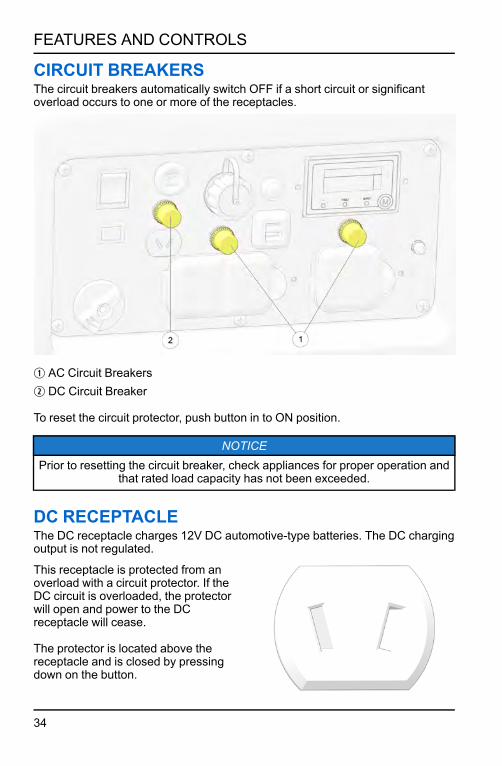
CIRCUIT BREAKERSThe circuit breakers automatically switch OFF if a short circuit or significantoverload occurs to one or more of the receptacles.
q AC Circuit Breakersw DC Circuit Breaker
To reset the circuit protector, push button in to ON position.
NOTICEPrior to resetting the circuit breaker, check appliances for proper operation and
that rated load capacity has not been exceeded.
DC RECEPTACLEThe DC receptacle charges 12V DC automotive-type batteries. The DC chargingoutput is not regulated.
This receptacle is protected from anoverload with a circuit protector. If theDC circuit is overloaded, the protectorwill open and power to the DCreceptacle will cease.
The protector is located above thereceptacle and is closed by pressingdown on the button.
34
FEATURES AND CONTROLS

120VAC TWIST LOCK RECEPTACLE120VAC receptacleq providesconnection for properly rated, 120VACappliances.
120V / 30 Amp
INDICATOR PANELINDICATOR LIGHT DESCRIPTION
Low Oil Indicator The low oil alarm system is designedto prevent engine damage caused byan insufficient amount of oil in thecrankcase. Before the oil level in thecrankcase falls below a safe limit, thelow oil alarm system will automaticallyshut down the engine (the engineswitch will remain in the ON position).
If the low oil alarm system shuts downthe engine the red low oil alarmindicator light will come on when youoperate the starter, and the engine willnot run. If this occurs, search for anyoil leaks. Add engine oil to resumenormal operation. See page 72 for oilrecommendation.
Fault / OverloadIndicator
If a short circuit occurs in a connectedappliance(s), or if the generator isoverloaded (produces more than 2800W), current to the connectedappliance will cease, the outputindicator (GREEN) will extinguish, andthe overload indicator will illuminateRED.
Output Indicator The output indicator illuminatesGREEN when the generator is innormal operation and producingelectrical power at the receptacles.
35
FEATURES AND CONTROLS

PARALLEL SOCKETTwo Polaris parallel-ready generators can be connected together to increase thetotal power available to a load, using the parallel socketq.
The system seamlessly matchesfrequency and automatically distributesthe load to each generator evenly soneither is overloaded.
Contact your dealer to purchase aPOLARIS parallel kit.
USB PORTSThis generator is equipped with twoUSB portsq. A total of 3.1A datatransfer speed is available at 5 volts.
Each single port can draw the full3.1A or will be distributed as needed.
36
FEATURES AND CONTROLS

ASSEMBLYIMPORTANCE OF PROPER ASSEMBLY
WARNINGImproper assembly can cause an unsafe condition that can lead to seriousinjury or death. Follow the assembly procedures and precautions in this
manual carefully.
Proper assembly is essential to operator safety and the reliability of yourgenerator. Errors and oversight made during unit assembly or service couldresult in faulty operation, damage to the machine, or operator injury.
UNBOXING1. Remove generator and loose parts from the box.
2. Compare loose parts to the inventory list below.
NOTICEContact your dealer if any of the loose parts listed below are not included with
your generator.
REF. NO. DESCRIPTION QUANTITY
q Left Cord Hook 1
w Left Hook Base 1
e Right Cord Hook 1
r Hex Nut 1
t Right Hook Base 1
37
ASSEMBLY

OTHER INCLUDED ITEMSInside your generator box, there should be the following items:
• Owner’s manual• Tool Kit• Warranty registration form
38
ASSEMBLY

EXTENSION CORD HOOKS
NOTICEA socket wrench and Allen wrench will be needed for assembly.
PARTSREF. NO. DESCRIPTION QUANTITY
q Left Cord Hook 1
w Hex Screw 1
e Left Hook Base 1
r Right Cord Hook 1
t Hex Nut 1
y Right Hook Base 1
u Handle Cap 1
39
ASSEMBLY

LEFT HOOK ASSEMBLY1. In the left rear corner of the generator, remove inner hex screww using an
Allen wrench.
2. Insert hook basee into opening on the frame.
3. Insert screww and tighten with an Allen wrench.
4. Twist the hookq into the base and tighten. The hook end should faceoutward.
40
ASSEMBLY

RIGHT HOOK ASSEMBLY1. In left front corner of the generator, remove capu from the generator’s
handle.
2. Remove hex nutt from screw.
3. Slip hook baser onto exposed screw.
4. Secure base with hex nutt using a socket wrench.
5. Twist the hooky into the base and tighten. Hook end should face outward.
41
ASSEMBLY

42
FIRST USE INSTRUCTIONSADDING ENGINE OIL
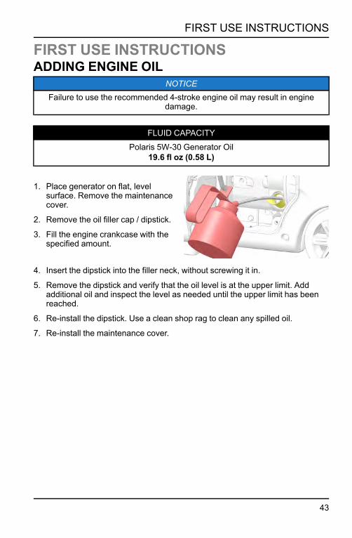
NOTICEFailure to use the recommended 4-stroke engine oil may result in engine
damage.
FLUID CAPACITYPolaris 5W-30 Generator Oil
19.6 fl oz (0.58 L)
1. Place generator on flat, levelsurface. Remove the maintenancecover.
2. Remove the oil filler cap / dipstick.
3. Fill the engine crankcase with thespecified amount.
4. Insert the dipstick into the filler neck, without screwing it in.
5. Remove the dipstick and verify that the oil level is at the upper limit. Addadditional oil and inspect the level as needed until the upper limit has beenreached.
6. Re-install the dipstick. Use a clean shop rag to clean any spilled oil.
7. Re-install the maintenance cover.
43
FIRST USE INSTRUCTIONS
FUELFUEL RECOMMENDATIONPolaris recommends the use of 87 octane fuel or higher.
WARNINGGasoline is highly flammable and explosive and can cause serious injury ordeath. Stop the engine and keep heat, sparks, and flame away. Handle fuel
only outdoors. Wipe up spills immediately.
CAUTION
Never use stale or contaminated gasoline or an oil /gasoline mixture. Avoidgetting dirt or water in the fuel tank.Do not spill fuel when filling the fuel tank. Damage caused by spilled fuel is notcovered under warranty. Spilled fuel is a fire hazard, causes environmentaldamage, and can damage paint and plastic. Wipe up spills immediately. Do notfill above bottom of strainer.Refuel in a well ventilated area before starting the engine. If the engine hasbeen running, allow it to cool.Never refuel the engine inside a building where vapors may reach flames orsparks. Keep fuel vapors away from electrical appliances.
CAUTIONDo not use fuel containing more than 10% ethanol. If the content of ethanol
exceeds the specified limits, it may cause starting or performance problems. Itmay also damage metal, rubber, and plastic parts of the fuel system. Do notuse gasoline containing methanol. Damage due to ethanol or methanol is not
covered under warranty.
IMPORTANT
Operating the generator with an obstructed fuel system will result in seriousengine damage. Perform maintenance as recommended.Thoroughly read “Safety” section and all safety information when handling fuel.In order to insure the optimum output and the maximum service life of thegenerator, the generator should run at a 50% load for the first 20 hours.
44
FIRST USE INSTRUCTIONS

ADDING FUELWARNING
Gasoline is highly flammable and gasoline vapor is explosive under certainconditions. Improper gasoline handling could result in severe injury or death.
Always use caution when handling gasoline.
To safely add fuel to the gas tank, perform the following steps.
1. Ensure fuel valve switch is OFF.
2. Remove the fuel tank capq.
3. Fill carefully to avoid spilling fuel on the fuel tank strainer. Do not overfill thefuel tank (there should be no fuel above the upper limit mark).
WARNINGDo not overfill. Fuel overflow may spill onto a hot engine and result in fire or
explosion.
4. Tighten fuel tank cap securely.
45
FIRST USE INSTRUCTIONS

5. Position fuel switch to OFF for storage or ON to operate the generator.
6. Move generator away from fueling source and site before starting engine.
46
FIRST USE INSTRUCTIONS

PRE-OPERATION INSPECTIONWARNING
Gasoline is highly flammable and explosive and can cause serious injury ordeath. Stop the engine and keep heat, sparks, and flame away. Handle fuel
only outdoors. Wipe up spills immediately.
CAUTIONFailure to perform the recommended pre-operation inspections could result inminor or moderate injury or property damage. When inspection reveals theneed for adjustment, replacement, or repair, perform service promptly or visit
your authorized Polaris dealer for assistance.
CAUTIONIf the engine has been running, the muffler will be very hot. Allow the muffler to
cool before servicing.
IMPORTANTAlways perform the recommended pre-operation inspections before each use
and when removing the generator from storage.
ITEM REMARKS PAGE
Engine Oil Check and add oil, as needed. See page 43and page 73.
Fuel Level Check the fuel level and refuel, asneeded. See page 49.
ExhaustSystem
Inspect the exhaust system for leakage.Tighten or replace gasket, as needed. See page 81.
Carburetor Inspect choke knob operation (ifequipped). See page 32.
Level Ground Ensure the generator is resting on alevel surface to prevent spills or tip-over.
–
Grass andLeaves
Remove grass, leaves, and otherflammable material or debris, especiallynear the HOTexhaust system.
See page 17.
47
FIRST USE INSTRUCTIONS

48

OPERATIONSAFE OPERATING PRECAUTIONSREFUELING
WARNINGGasoline is highly flammable and explosive and can cause serious injury ordeath. Stop the engine and keep heat, sparks, and flame away. Handle fuelonly outdoors. Wipe up spills immediately.Thoroughly read the Safety chapter
of this manual before handling fuel.
CAUTION
Do not spill fuel when filling the fuel tank. Damage caused by spilled fuel is notcovered under warranty. Spilled fuel is a fire hazard, caused environmentaldamage, and can damage paint and plastic. Wipe up spills immediately. Do notfill above bottom of strainer.Refuel in a well ventilated area before starting the engine. If the engine hasbeen running, allow to cool before refueling.Never refuel the engine inside a building where vapors may reach flames orsparks. Keep fuel vapors away from electrical appliances.Do not overfill the fuel tank (there should be no fuel in the filler neck). Afterrefueling, make sure the fuel filler cap is closed properly and securely.
To safely refuel the gas tank, perform the following steps.
1. Ensure fuel valve switch is OFF.
2. Remove fuel tank cap.
3. Fill carefully to avoid spilling fuel on the fuel tank strainer. Do not overfill thefuel tank (there should be no fuel above the upper limit mark).
WARNINGDo not overfill. Fuel overflow may spill onto a hot engine and result in fire or
explosion.
4. Tighten fuel tank cap securely.
5. Position fuel valve switch to OFF for storage or ON to operate the generator.
6. Move generator away from the fueling site and fuel source before starting theengine.
49
OPERATION

STARTING THE ENGINEDANGER
Never operate a generator indoors. Engine exhaust contains carbonmonoxide, an odorless, colorless gas that can kill you within minutes. Always
use this generator outdoors in a well-ventilated area.
WARNING
Before starting the engine, take the following precautions:• Ensure the generator is away from the fueling source.• The generator will vibrate during operation. Place the generator in a drylocation and on a flat, level surface.
• Unplug all power cords and extension cords from the generator.• Engage the wheel locks (if installed).• Perform an oil, fuel, and air filter check.
ELECTRIC START1. Ensure the generator is away from
the fueling source.
2. Unplug all power cords andextension cords from the generator.
3. Turn the fuel valve switch to ON.
4. For a cold engine start, position thechoke lever (if equipped) to CLOSE.To restart a warm engine, leave thechoke lever in OPEN.
NOTICEIf your generator is not equipped with a manual choke, the internal battery
must be at full charge to operate the electric choke.
5. To start the generator using electric start, momentarily press down on the topof the ignition switch to the STARTq position. The switch will default back tothe RUNw position. To stop the engine, press the bottom of the switch to theOFFe position.
50
OPERATION

NOTICEIf the electric starter fails, the battery is likely drained. Charge the battery
before attempting to restart.
REMOTE STARTThe remote fob requires a CR1632 lithium cell battery.
The life expectancy for this battery is two years. To replace battery, unscrewand remove the back panel of the remote fob.
1. Set Ignition Switch to RUN position.
2. Open the fuel valve by turning fuelswitch to OPEN position.
3. Press the ON button firmly on theremote fob to start the engine.
NOTICERemote start does not have a run limit.The engine will continue to run until
fuel is depleted.
4. Press the OFF button on the fob toshut down the engine.
IMPORTANTIf engine does not turn over, wait five seconds and press ON button again. If
remote start continues to fail, see page 97.
51
OPERATION

RECOIL START1. To start the generator using the
recoil, lightly pull the starter recoilgripq until resistance is felt. Then,firmly pull straight out.
NOTICEDo not allow starter grip to snap backagainst the generator. Return it gentlyto prevent damage to the starter.
2. For a cold engine start, pull out the choke lever (if equipped) to CLOSEDposition.
3. If the choke lever was positioned to CLOSED to start the engine, move it toOPEN as the engine warms up.
NOTICEIf your model is not equipped with a manual choke, the battery must be
charged to operate the electric choke.
STOPPING THE ENGINENOTICE
Continually stopping the generator with a load applied can lead to damage ofthe control module.
In case of emergency, turn ignition switch to OFF position to stop the engine.Under normal conditions, perform the following procedure:
1. Shut off or disconnect all appliances connected to the generator.
2. Turn ignition switch to OFF.
3. Turn fuel valve switch to OFF.
52
OPERATION

PARALLEL OPERATIONWARNING
Only connect a parallel capable Polaris inverter generator with the approvedparallel cable. Attempting to connect a different generator brand in parallel with
your generator will void your warranty and could cause severe injury.Do not start the generators before connecting the parallel cable. Running onegenerator with the cable connected will cause an overload and require an
engine reset.If the overload indicator light remains on after resetting the generator, stop the
engine and wait five minutes before restarting.
NOTICE
• For continuous operation, do not exceed the combined rated power of theparalleled generators.
• Do not run the generators longer than 30 minutes at max output.• Always stop both engines before connecting or removing the parallel cable.• Always remove the parallel cable completely if operating a single unit.
To run generators in parallel, complete the following steps:
1. Ensure both generators are off andfuel valves are closed.
2. Connect the AC parallel cable to theparallel socketq on each generator.
3. Ensure all appliances are off anddisconnected.
4. Start each generator and thenconnect the appliance to the parallelcable.
5. Turn on appliance.
53
OPERATION

AC OPERATIONWARNING
Before connecting a device or power cord to the generator, ensure it is in goodcondition. Faulty appliances or power cords can create a potential for electrical
shock.If an appliance begins to operate abnormally, becomes sluggish, or suddenlystops, immediately shut it off. Disconnect the appliance and determine whetherthe problem is the appliance or if the rated load capacity of the generator hasbeen exceeded.Ensure the combined electrical rating of the device or appliance does notexceed the maximum allowed by the generator. Never exceed the maximumpower rating of the generator. Do not exceed the current limit specified for anyone receptacle. Power levels between rated and maximum may be used for nomore than 30 minutes.
IMPORTANT: Before connecting a device or power cord to the generator,ensure the device or cord is in good condition and electrical rating does not
exceed the maximum amount allowed by the generator.
1. Start engine. See page 50 for additional instruction.
2. Confirm the desired appliance is switched off. Then plug the appliance orextension cord into one of the AC receptacles.
3. Turn on the appliance.
54
OPERATION

NOTICEShould the generator's maximum load of 25 amps be exceeded, the circuit
protection device will trip and cut all current to the receptacles. The engine willcontinue to run.Correct the load by unplugging all appliances from the
receptacles and press-in the circuit protector button to reset, followed by theOverload Reset button. AC power will be restored immediately.
AC CAPACITYMODEL MAX POWER RATED POWER
P3200iE 2800 W 3200 W
NOTICE
In case of substantial overloading, the electronic circuit protector will activate.Slightly overloading the generator or running at maximum power operation (30minutes) may not switch the circuit ON, but will shorten the service life of the
generator.
Consider total power requirements of all connected devices. Appliance andpower-tool manufacturers typically list rating information near the model or serialnumber. After plugging in a device, allow the generator to stabilize beforeplugging in additional items. Always consider generator capacity before pluggingin any device.
Typical wattages are listed in the table below. Before plugging any device intothe generator, verify the manufacturer-listed wattage on the device.
55
OPERATION

WATTAGE REFERENCE TABLEDEVICE RUNNING (RATED) WATTS ADDITIONAL STARTING
(SURGE) WATTS
Table Saw / Radial Arm Saw -10”
2000 2000
Space / Wall Heater 1800 0
Central Air Conditioning 1500 4500
Circular Saw - 7 1/4” 1400 2300
Hair Dryer 300 - 1200 0
Sump Pump - 1/2 HP 1050 2200
Microwave Oven - 100 Watt 1000 1400
Coffee Maker 1000 0
Garage Door Opener 1/2 HP 875 2350
Personal Computer w/ 17”Monitor
800 0
Refrigerator 400 - 800 2200
Dehumidifier 650 800
Color Television - 27” 500 0
Electric Drill - 3/8”, 4 amps 440 600
Paint Sprayer 360 1080
Radio 300 300
Oven 60 7500
Light Bulb - 75 Watt 75 0
POWER MANAGEMENT EXAMPLEDEVICE RUNNING (RATED) WATTS ADDITIONAL STARTING
(SURGE) WATTS
Radio 300 W 300 W
Space Heater 1800 W 0
2100 = Total Running (Rated) Watts300 = Additional Starting (Surge) Watts2400 = Total Generator Output Required
56
OPERATION

CAUTIONEnsure the combined electrical rating of the powered device(s) do not exceedthe maximum output allowed by the generator. Never exceed the maximumpower rating of the generator. Power levels between rated and maximum may
be used for no more than 30 minutes.
DC OPERATIONThe DC Receptacle on this generator is designed to charge 12V DC batteries. Itis not designed to operate DC motors.
CAUTIONThis generator is not designed to operate DC motors. The DC charging outputis not regulated. The DC receptacle should only be used for charging 12V DC
batteries. Output voltage is 15-30V.The DC output is to be used to charge batteries only. Serious damage to the
stator windings can occur if connected to a DC motor or transformer.
BATTERY CHARGINGWARNING
The battery emits explosive hydrogen gas during normal operation. A spark orflame can cause the battery to explode with enough force to kill or cause
serious injury. Wear protective clothing and eye protection when charging abattery. Failure to adhere to these safety precautions could lead to severe
injury or death.Battery posts, terminals, and related accessories contain lead and lead
components. Wash hands after handling.To prevent the possibility of creating sparks near the battery, connect the
charging cable first to the generator then to the battery. Disconnect the cablefirst at the battery.
The battery contains sulfuric acid (electrolyte). Contact with skin or eyes maycause severe burns. Wear protective clothing and a face shield. If electrolytegets on your skin, flush with water. If electrolytes get in your eyes, flush with
water for at least 15 minutes and call a physician.Electrolyte is poisonous. If swallowed, drink large quantities of water or milk
and follow with milk of magnesia or vegetable oil and call a physician. Keep outof reach of children.
57
OPERATION

CONNECTING THE BATTERY CHARGING CABLECAUTION
Do not start the vehicle while the battery charging cable is connected and thegenerator is running. The vehicle’s charging system or the generator may be
damaged.
1. Disconnect the ground cable fromthe negative (-) battery terminal,followed by the positive (+) cable.
2. Plug the battery charging cable intothe DC receptacle.
3. Connect the red lead of the batterycharging cable to the positive (+)battery terminal and then the blacklead to negative (-) battery terminal.Do not reverse the charging cablesor serious damage to the generatorand/or battery may occur.
4. Ensure the SMART throttle switch isOFF.
5. Start the generator.
DC CIRCUIT OVERLOADThe DC receptacle is protected from an overload with a circuit protector. If theDC circuit is overloaded, the protector will trip and power to the DC receptaclewill cease.
If the circuit protector keeps tripping, discontinue charging and see yourauthorized Polaris generator dealer.
NOTICE
The circuit protector does not prevent overcharging of the battery.
DISCONNECTING THE BATTERY CHARGING CABLE1. Stop the generator.
2. Disconnect the black lead of the battery charging cable from the negative (-)battery terminal and then the lead from the positive (+) battery terminal.
3. Unplug the battery charging cable from the DC receptacle.
58
OPERATION
4. Connect the vehicle battery ground cable to the positive (+) battery terminal.
5. Connect the vehicle battery ground cable to the negative (-) battery terminal.
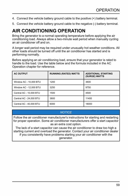
AIR CONDITIONING OPERATIONBring the generator to a normal operating temperature before applying the airconditioning load. Always allow a two-minute wait period when manually cyclingan air conditioner off and on.
A longer wait period may be required under unusually hot weather conditions. Allother loads should be turned off until the air conditioner has started and isperforming normally.
Before applying an air conditioning load, ensure that your generator is rated tohandle to the load. Use the table below and the formula included in the ACOperation chapter for reference.
AC OUTPUT RUNNING (RATED) WATTS ADDITIONAL STARTING(SURGE) WATTS
Window AC - 10,000 BTU 1200 3600
Window AC - 12,000 BTU 3250 9750
Central AC - 10,000 BTU 1500 4500
Central AC - 24,000 BTU 3800 11400
Central AC - 40,000 BTU 6000 18000
NOTICE
Follow the air conditioner manufacturer's instructions for starting and restartingfor proper operation. Some air conditioner manufacturers offer a start capacitor
as an extra cost option.The lack of a start capacitor can cause the air conditioner to draw too high a
starting current and overload the generator. Contact your air conditioner dealerif you consistently have problems starting your air conditioner with the
generator.
59
OPERATION

STANDBY POWERCONNECTIONS TO A BUILDING ELECTRICALSYSTEM
WARNINGImproper connection to a building electrical system can allow current from thegenerator to back feed into the utility lines. Such back feed may electrocute
utility company workers or others who contact the lines during a power outage.Additionally, the generator may explode, burn, or cause fires when utility poweris restored. Consult the utility company or a qualified electrician prior to making
any power connections.
Connections for standby power to a building's electrical system must be madeby a qualified electrician and must comply with all applicable laws and electricalcodes. Improper connections can allow electrical current from the generator toback feed into the utility lines.
Such back feed may electrocute utility company workers or others who contactthe lines during a power outage; when utility power is restored, the generatormay explode, burn, or cause fires in the building's electrical system. Do notconnect this generator to an automatic transfer switch. Serious damage to theengine and inverter module may result.
In some areas, generators are lawfully required to be registered with local utilitycompanies. Check local regulations for proper registration and usageprocedures.
60
OPERATION

GROUND SYSTEMThis generator is equipped with a system ground to prevent electrical shockfrom faulty appliances.
To ground this generator, perform the following steps:
1. Ensure engine is OFF and fuel valve switch is OFF.
2. Using a mallet, drive a grounding rod 4 ft. into the ground.
3. Wrap a length of bare copper grounding wire tightly around the groundingrod or use a grounding clamp.
4. Slightly loosen bolt on groundterminal. Allow enough space towrap copper wire.
5. Using the other end of the copperwire, tightly wrap the wire aroundthe terminal.
SYSTEM REQUIREMENTSThere may be federal or state Occupational Safety and Health Administration(OSHA) regulations, local codes, or ordinances that apply to the intended use ofthe generator. Please consult a qualified electrician, electrical inspector, or thelocal agency having jurisdiction.
If the generator is used at a construction site, there may be additional regulatoryrequirements.
61
OPERATION

HIGH ALTITUDE USECARBURETOR MODIFICATION
NOTICE
When carburetor has been modified for high altitude operation, the air-fuelmixture will be too lean for low altitude use and may cause engine damage.At high altitude, the standard carburetor air-fuel mixture will be excessively
rich. Performance will decrease and fuel consumption will increase. A very richmixture will also foul the spark plug and cause hard starting. Operation at analtitude different than that which this engine was certified, for extended periods
of time, may increase emissions.
High altitude operation can be improved by specific modifications to thecarburetor. If always operating the generator at altitudes above 3000 feet (915meters), have an authorized Polaris servicing dealer perform the carburetormodification. The engine will meet each emission standard throughout its lifewhen operated at high altitude with the carburetor modifications for high altitudeoperation.
With the carburetor modification, engine horsepower will decrease by about3.5% for every 1000 feet (300 meters) increase in altitude. The effect of altitudeon horsepower will be greater if no carburetor modification is made.
CAUTIONOperation of the generator at an altitude lower than the carburetor is jetted formay result in reduced performance, overheating, and serious engine damage
caused by an excessively lean air/fuel mixture. Be sure to have anymodification reversed at lower altitudes.
ALTITUDE KITSFor added convenience, POLARIS offers high altitude kits which optimizeperformance and fuel consumption at various altitude ranges. For installationinstruction, see page 75.
MODEL PART NUMBER DESCRIPTION
P2000i 2884865 K-HIGH,ALT,3-8K,P2000I
P3200iE 2884866 K-HIGH,ALT,3-8K,P3200IE
P5500 / P6500 2884867 K-HIGH,ALT,3-8K,P5500/6500
62
OPERATION

EMISSION CONTROL SYSTEMSSOURCE OF EMISSIONSExhaust gas contains carbon monoxide, nitrous oxide (NOx), and hydrocarbons.It is very important to control the emissions of NOx and hydrocarbons as theyare a major contributor to air pollution. Carbon monoxide is a poisonous gas.The emission of fuel vapors is a source of pollution as well. The generatorengine utilizes a precise air-fuel ratio and emission control system to reduce theemissions of carbon monoxide, NOx, hydrocarbons, and evaporative fuelemissions.
Polaris utilizes appropriate air-fuel ratios and other emissions control systems toreduce the emissions of carbon monoxide, oxides of nitrogen, andhydrocarbons. In addition, Polaris fuel systems utilize components and controltechnologies to reduce evaporative emissions.
U.S. AND CALIFORNIA CLEAN AIR ACTSYour engine has been designed to meet current Environmental ProtectionAgency (EPA) and the California Air Resources Board (CARB) clean airstandards. The regulations dictate that the manufacturers provide operation andmaintenance standards regarding the emission control system. Tune upspecifications are provided in the Maintenance section. Adherence to thespecified maintenance instructions is essential for your engine to meet theemission control standards.
ALTERATIONSAltering the emission control system may increase emissions beyond the legallimit. Some possible alterations are removal or alteration of any part of theintake, fuel, or exhaust systems.
PROBLEMS AFFECTING EMISSIONSIf aware of any of the following, have the engine inspected and repaired by anauthorized Polaris dealer:
• Hard starting or stalling after starting• Rough idle• Shut down or backfire after applying an electrical load• Afterburning (backfiring)• Black exhaust smoke or high fuel consumption
63
EMISSION CONTROL SYSTEMS

REPLACEMENT PARTSThe emission control system on the engine was designed, built, and certified toconform to applicable emission regulations. We recommend the use of PolarisGenuine parts whenever maintenance is performed. These original-designreplacement parts are manufactured to the same standards as the original parts.The use of replacement parts that are not of the original design and quality mayimpair the effectiveness of the emission control system.
Aftermarket part manufacturers assume the responsibility that the part will notadversely affect emission performance. The manufacturer or re-builder of thepart must certify that use of the part will not result in a failure of the engine tocomply with emission regulations.
64
EMISSION CONTROL SYSTEMS

MAINTENANCEIMPORTANCE OF MAINTENANCEGood maintenance is essential for safe and economical operation. Propermaintenance will also help reduce air pollution. Always follow therecommendations for inspection and maintenance as specified in this manual.
WARNINGImproper maintenance, or failure to fix problems prior to operation, could lead
to generator malfunction resulting in serious injury or death.
The following chapter includes a periodic maintenance schedule, includingproper inspection and maintenance procedure. The maintenance scheduleapplies to normal operating conditions. This maintenance is essential to thelongevity of your generator.
Any qualified repair shop or person may maintain, replace or repair the emissioncontrol devices or systems on your generator. POLARIS also recommendsPOLARIS parts for emissions-related service, however equivalent parts can beused.
IMPORTANTIt is a potential violation of the Clean Air Act if a part, supplied by an
aftermarket parts manufacturer, reduces the effectiveness of the generator’semission controls. Tampering with emission controls is prohibited by federal
law.
Owners are responsible for performing the scheduled maintenance identified inthis owner’s manual. Careful periodic maintenance will help keep your generatorin safe, reliable condition. Inspect, clean, lubricate, adjust and replace parts asnecessary. Other, more difficult tasks, require special tools and expertiseprovided by an authorized Polaris technician or other qualified mechanic.
If the generator is operated under unusual conditions, such as sustained highload or high temperature, or dusty conditions, consult the servicing dealer forapplicable recommendations.
All necessary replacement parts and labor incurred, with the exception ofauthorized warranty repairs, become the responsibility of the registered owner.If, during the course of the warranty period, part failures occur as a result ofowner neglect in performing recommended regular maintenance, the cost ofrepairs are the responsibility of the owner.
65
MAINTENANCE

TOOL KITThis generator is packaged witha tool kit to help with basicrepair and maintenance.
REF.NO.
TOOL DESCRIPTION QUANTITY
q Oil Fill Funnel 1
w 12V DC Cable 1
e Spark Plug Wrench Handle 1
r Spark Plug Wrench 1
t Screwdriver 1
y Key Fob 2
66
MAINTENANCE

MAINTENANCE SAFETYCAUTION
After any maintenance is performed, wash skin immediately using soap andclean water as exposure to lubricant may cause skin irritation.
WARNINGPersonal safety is critical when attempting to service the generator. Improperly
installed or adjusted components can make the generator unstable ordangerous. Improperly installed electrical components can cause engine or
electrical systems failure. In either event, damage or serious injury could result.If you do not have the time, tools, and/or expertise necessary to complete a
procedure properly, please see your Polaris dealer or other certified technicianfor service.
Failure to correct a problem before operation and improper maintenance cancause a malfunction resulting in injury or death. Always follow the inspection
and maintenance schedules and requirements in this manual.
The following important safety precautions cannot warn of every possible hazardfrom maintenance. The decision to perform a given task must be evaluated bythe individual performing it.
SAFETY PRECAUTIONSRead the safety section of this manual.
Ensure the engine is off before performing any maintenance or repairs tominimize the potential for exposure to the following hazards:
• Fuel and fire - Avoid flames, sparks, and smoking during service.• Carbon monoxide poisoning - Do not operate engine indoors. Whenoperating outdoors, avoid open windows and doors.
• Burns - Allow the engine and exhaust system to cool before touching.Exercise caution when working around hazardous materials.
• Injury from moving parts - Avoid running the engine unless specificallyinstructed.
Follow the instructions and ensure the required tools are used.
Exercise caution when working around gasoline to reduce the possibility of fireor explosion. Use only non-flammable solvents to clean parts. Keep cigarettes,sparks, and flames away from all fuel-related components.
67
MAINTENANCE

PERIODIC MAINTENANCEPrior to performing any maintenance on your generator,
• Always stop the engine before servicing. Disconnect all devices andextension cords to avoid receiving an electrical shock.
• Periodic checks and maintenance are very important for keeping thegenerator in good condition.
• Inspect, clean, lubricate, adjust, and replace parts as necessary. Wheninspection reveals the need for replacement parts, use Polaris Genuine partsavailable from your Polaris dealer.
• Before beginning any maintenance procedure, read the instructions for theentire procedure. During some procedures, potentially hazardous productsmay be used. Always follow the instructions and warnings on the productpackaging.
68
MAINTENANCE

PERIODIC MAINTENANCE CHARTITEM REMARKS PRE-
OPERA-TIONCHECK(DAILY)
INITIAL 1MONTHOR 20HOURS
EVERY 3MONTHSOR 50HOURS
EVERY 6MONTHSOR 100HOURS
EVERY 12MONTHSOR 300HOURS
Spark Plug
Checkcondition.Adjust gapand clean.Replace asneeded.
X
SparkArrester
Clean thecarbondeposits.
X
Engine Oil
Check theoil level. X
Replaceoil. X X
Air Filter
Checkfilter. X
Clean.Replace asneeded.
X₂
FuelSedimentCup
Clean.X
Fuel TankandStrainer
Clean.X₃
ValveClearance
Check andadjustwhenengine iscold.
X₃
Fuel Line
Check fuelline fortwists,cracks, ordamage.Replace asneeded.
Every 2 years (Replace as necessary)₃
1. Log hours of operation to determine proper maintenance.
2. Service more frequently when used in dusty conditions.
3. These items should be serviced by an authorized Polaris dealer unless the owner has the propertools and is mechanically proficient. Refer to the Polaris Service manuals.
69
MAINTENANCE

REMOVING THE MAINTENANCE COVERUse the following steps to remove the generator maintenance cover and gainaccess to the inner components. Before performing any maintenance, theignition switch should be positioned to OFF.
1. Position the ignition switch and fuel valve lever to OFF.
2. Remove the two screwsq from the maintenance cover.
3. Pull down on the lip of the coverw to expose the inner components of thegenerator.
4. Perform maintenance as needed.
5. Upon completion of maintenance, replace cover by inserting the bottom edgeinto the grooves and replacing the two screws.
70
MAINTENANCE

FUEL SYSTEMWARNING
Gasoline is highly flammable and explosive, and can cause serious injury ordeath. Stop the engine and keep heat, sparks, and flame away. Handle fuel
only outdoors. Wipe up spills immediately.
FUEL LINE INSPECTIONInspect the fuel line to ensure absence of twists, cracks, and / or damage.Replace as needed.
GAS TANK STRAINER1. Remove the fuel tank cap.
2. Remove the fuel tank strainer from the fuel tank.
3. Remove any foreign objects or debris from the fuel tank strainer.
4. Inspect the fuel tank strainer for damage. Replace as needed.
5. Install the fuel tank strainer into the fuel tank.
6. Securely tighten the fuel tank cap.
7. Position the fuel valve switch OFF for storage or transport, or ON to run thegenerator.
FUEL LINEInspect the fuel hose for cracks or damage. Replace as needed. See page 71for more information about the fuel system.
71
MAINTENANCE

ENGINE OILOIL RECOMMENDATION
Oil RecommendationPOLARIS 5W-30 Generator Oil
Oil directly affects performance and service life. Use a 4-stroke automotivedetergent oil, see page 95 for recommended oil. Other viscosities may be usedwhen the applicable average temperature is within the recommended range.
The SAE oil viscosity and service category are in the API label on the oilcontainer. Polaris recommends the use of API service category “SJ” or later,equivalent oil.
OIL LEVEL INSPECTIONCAUTION
Failure to use the proper 4-stroke engine oil may result in engine damage.Using non-recommended oil may cause serious engine damage. Neversubstitute or mix oil brands.Inspect the oil level before each use with the engine stopped and the generatoron a level surface.
1. Remove the oil filler cap / dipstick and wipe it clean.
2. Insert the dipstick into filler neck, without screwing it in, to inspect the oillevel.
3. Remove the dipstick and verify that the oil is at the upper limit. Add additionaloil and inspect the level as needed until the upper limit has been reached.
4. Re-install the dipstick. Use a clean shop rag to clean any spilled oil.
72
MAINTENANCE

NOTICE
• Do not tilt generator when adding engine oil. This could result in overfillingand damage to the engine.
• Use high quality 4-stroke engine oil, certified to meet or exceed APIstandard SG, SF, SAE ratings with strong detergents. Using non-detergentor 2-stroke oil could shorten the engine’s working life.
• Do not mix different engine oils.• Handle and store the engine oil with care, avoid getting dirt or dust into theengine oil.
• Before the engine oil falls below the safety margin, the low oil alert system illautomatically shut off the engine. The low oil light (RED) will illuminate.
• To avoid the inconvenience of unexpected engine shutdown, check oil levelbefore each use.
OIL CHANGEWARNING
Oil may be hot. Do not allow hot oil to come into contact with skin, as seriousburns may result.
NOTICEDrain the oil while the engine is warm to assure rapid and complete draining.
IMPORTANTImproper disposal of engine oil can be harmful to the environment and is
unlawful. Properly dispose of used oil.
1. Start the engine and allow it to runfor a few minutes. Stop the engine.
2. Position the fuel valve switch toOFF.
3. Elevate the generator severalinches above the ground.
4. Open the oil access door toexpose oil drainq.
5. Remove the oil filler cap / dipstick.
6. Place a drain pan under the generator.
73
MAINTENANCE

7. Remove the drain boltw andsealing washere from the bottomof the generator.
8. Drain the used oil into a sealedcontainer and take it to a recyclingcenter. Do not discard the oil in atrash can, dump it on theground, or pour it down thedrain.
9. Re-install the washer and drainbolt.
10.Place provided funnel into fill valve.
11. Fill oil to the high limit mark on the dipstick. Ensure that the oil level does notrise past the threading of the cap.
FLUID CAPACITYPolaris 5W-30 Generator Oil
19.6 fl oz (0.58 L)
12.Remove funnel and re-install the dipstick. Do not screw in.
13.Start the engine and let run for 1 or 2 minutes. Stop the engine and check forleaks.
14.Re-check the oil level on the dipstick and add oil as needed to bring the levelto the upper mark on the dipstick.
15.Re-install the dipstick.
16.Re-install oil access door securely.
17.Wash hands with soap and water after handling used oil.
74
MAINTENANCE

HIGH ALTITUDE JETSWARNING
Gasoline is highly flammable and is explosive. You can be burned or seriouslyinjured when handling fuel. Keep heat, sparks, and flame away. Wipe up spills
immediately.
NOTICEUsing the wrong carburetor main jet may cause poor engine performance. If
too lean of a main jet is used, severe engine damage may result.
ALTITUDE KITSMODEL PART
NUMBERDESCRIPTION
P2000i 2884865 K-HIGH,ALT,3-8K,P2000I
P3200iE 2884866 K-HIGH,ALT,3-8K,P3200IE
P5500 / P6500 2884867 K-HIGH,ALT,3-8K,P5500/6500
ALTITUDE JET SPECIFICATIONSMODEL ENGINE ALTITUDE ALTITUDE JET MARK
P2000i 79cc3000-6000 ft 68
6000-8000 ft 67
P3200iE 208cc3000-6000 ft 74
6000-8000 ft 73
P5500 389cc3000-6000 ft 103
6000-8000 ft 101
P6500 420cc3000-6000 ft 107
6000-8000 ft 105
JET INSTALLATIONTo change the carburetor main jet, follow this procedure:
75
MAINTENANCE

NOTICEThe air box may need to be removed in order to gain enough clearance to
remove the main jet.
1. Turn off the fuel supply.
2. Remove the maintenance cover.
3. Access the carburetor drain screw. Drain the fuel from the carburetor into asuitable container.
4. Remove the float bowl and chamber bolt.
5. Remove the main jet from the carburetor.
6. Install the correct main jet for the altitude in which the generator is operating.Do not over-tighten the jet.
7. Re-install the float bowl and chamber bolt.
8. Close carburetor drain screw.
9. Re-install the maintenance cover.
10.Turn on fuel supply. Start generator and let engine run for several minutes.
11. Turn off generator. Verify there are no fuel leaks.
76
MAINTENANCE

AIR FILTERWARNING
Do not use gasoline or low flash point solvents for cleaning. They areflammable and explosive under certain conditions.
NOTICEAn obstructed air filter restricts air flow to the carburetor. To prevent carburetor
malfunction, regularly service the air filter. Service more frequently whenoperating generator in extremely dusty conditions.
1. Detach maintenance cover.
2. If necessary, move fuel hoses out of the way to expose air box.
3. Remove two screwsq to open the air box.
4. Extract air filter from box.
4. If filter is dirty or torn, replace it with a new one.
5. Re-install air box cover and secure with screws.
6. Move fuel hoses back into position.
7. Re-install the maintenance cover.
77
MAINTENANCE

IMPORTANTWhen replacing the filter, check that the filter is not pinched between the air
box covers to ensure a proper seal.
FOAM FILTERSIf using a foam air filter, follow the steps below to clean the filter before replacingit in the air box.
1. Submerge the filter in a solution of warm water and household detergent.
2. Let the filter soak in the solution for a few minutes and then squeeze out theexcess water.
3. Repeat step 2 several times to ensure the water coming from the filter isclean. Then let the filter dry completely.
4. Once dry, pour air filter oil onto the filter and distribute evenly. Be sure to ridthe filter of excess oil.
NOTICEThe use of air filter oil allows the filter to catch even the smallest particles of dirt
and dust.
5. If at any point during the cleaning process the filter becomes damaged, thenit must be replaced prior to operating your generator.
SPARK PLUGSPARK PLUG INSPECTIONUsing a non-recommended spark plug can result in serious engine damage.Always use recommended spark plugs. Refer to the Specification section for therecommended spark plug type. Always torque spark plugs to the specification.
In order to service the spark plug, the provided spark plug wrench is required.
CAUTIONA hot exhaust system and engine can cause burns. Wear protective gloves
when removing a spark plug for inspection.
IMPORTANTTo ensure proper engine operation, the spark plug must be free of depositsand properly gapped. If the engine has been running, allow it to cool before
servicing.
78
MAINTENANCE

1. Open the maintenance cover.
2. Remove the spark plug capq.
3. Clean any dirt from around the baseof the spark plug.
4. Using the provided park plugwrench, remove the spark plug.
5. Inspect the electrode for wear andcarbon buildup. Look for a sharpouter edge with no rounding orerosion of the electrode.
6. Inspect spark plug. Replace if electrodes are worn or if insulator is cracked,chipped, or fouled.
7. Clean the spark plug with a wire brush if it is to be reused.
NORMAL PLUGThe normal insulator tip is gray, tan or light brown. There will be few combustiondeposits. The electrodes are not burned or eroded.
This indicates the proper type and heat range for the engine and the service.
WET FOULED PLUGThe wet fouled insulator tip is black. A damp oil film covers the firing end. Theremay be a carbon layer over the entire nose. Generally, the electrodes are notworn. Fouling may be caused by excessive oil or by frequent short trips,especially in cold weather.
SPARK PLUG REPLACEMENTIMPORTANT
Prior to replacing the spark plug, complete the inspection steps outlined onpage 78.
1. Open the maintenance cover.
2. Remove the spark plug cap.
3. Clean any dirt from around the base of the spark plug.
4. Using the provided park plug wrench, remove the spark plug.
79
MAINTENANCE

5. Using a wire-type feeler gauge, measure the spark plug electrode gap. Ifnecessary, correct the gap by carefully bending the side electrode.
MEASUREMENTSpark Plug Gap
0.024- 0.028 in (0.6-0.7 mm)
6. Ensure the spark plug sealing washer is in good condition and thread thespark plug in by hand to prevent cross-threading.
7. After a new spark plug has been seated by hand, it should be tightened 1/2turn with a wrench to compress the sealing washer. If a used plug is beingreinstalled, it should only require 1/8 to 1/4 turn after being seated.
8. Re-install the spark plug cap and close the maintenance cover.
NOTICE
A loose spark plug can overheat and damage the engine. Over tightening thespark plug can damage the plug threads.
Never use a spark plug with an improper heat range.
80
MAINTENANCE

SPARK ARRESTERThe spark arrester is located on the end of the muffler.
WARNINGGenerator exhaust system gets hot enough to ignite some materials and burn
skin if touched.Allow generator and exhaust to cool before performing spark arrestor
maintenance.
CAUTIONThe spark arrester must be serviced every 100 hours to maintain its efficiency.
Before performing any inspection or maintenance on the battery, ignition switchshould be positioned to OFF.
REMOVING THE BACK PANELThe back panel and rear handle of the generator must be removed in order toaccess the muffler and the spark arrester. Allow the generator to fully cool beforetouching internal components.
81
MAINTENANCE

1. Remove the left handle screww.
2. Detach the rear cord hooke and right handle screwr.
3. Detach rear panel by removing the four screwst.
REMOVING THE SPARK ARRESTER
1. Remove screwy holding the spark arrester to the muffler.
2. Pull the end cap off to remove the arrester screen.
3. Clean the spark arrestor with a stiff wire brush.
4. Replace if the wire mesh is perforated or torn.
5. Reinstall screen and cap. Secure cap to the muffler with the screw.
82
MAINTENANCE

BATTERYWARNING
Always disconnect the negative (black) cable first when removing the battery.Always connect the negative (black) cable last during installation. Failure toproperly connect/disconnect battery cables may result in an explosion and
cause serious injury or death.Battery electrolyte contains sulfuric acid which is poisonous and can causeserious burns. Avoid contact with eyes, skin, and clothing. Ensure proper
protective gloves, goggles, and clothing are worn. If eyes are exposed, flushwith water for 15 minutes and seek medical attention. If external contact, flushwith water. If ingested, drink large quantities of water or milk. Follow with milk
of magnesia, beaten egg, or vegetable oil. Seek immediate attention.Overheating of battery may cause an explosion, and severe injury or death.Stop charging if the battery becomes very warm to the touch. Allow battery to
completely cool before resuming charging.
IMPORTANTAlways keep battery terminals and connections free of corrosion. Avoid spilling
of electrolyte. Damage to equipment may result.Immediately wash off any electrolyte spills with a solution of one tablespoon
baking soda and one cup water.If cleaning is necessary, remove corrosion witha stiff wire brush. Wash with a solution of one tablespoon baking soda and onecup water. Rinse well with tap water and dry off with clean shop towels. Coat
the terminals with dielectric grease or petroleum jelly.
BATTERY REMOVAL1. The battery is located at the front of
the generator, just below the controlpanel.
2. To expose the battery, detach thebattery access panel by removingthe two screws.
3. Disconnect the battery hold-downstrap.
4. Lift the batteryq out of the generator.
83
MAINTENANCE

5. Disconnect the black (negative) battery cable first by removing the M5 screww.
6. Disconnect the red (positive) battery cable last by removing the M5 screww.
BATTERY INSTALLATIONUsing a new battery that has not been fully charged can damage the battery andresult in a shorter life. It can also hinder generator performance. Follow theinstructions in the Battery Charging section before installing the battery.
1. Ensure that the battery is fully charged.
2. Place the battery in the battery holder.
3. Coat the terminals with dielectric grease or petroleum jelly.
4. Secure the battery hold-down strap.
5. Connect and tighten the red (positive) cable first.
6. Connect and tighten the black (negative) cable last.
7. Verify that cables are properly routed. Cables should be safely tucked awayat the front and rear of the battery.
8. Re-install the battery access panel.
84
MAINTENANCE
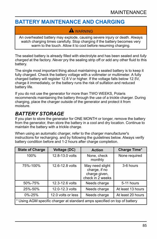
BATTERY MAINTENANCE AND CHARGINGWARNING
An overheated battery may explode, causing severe injury or death. Alwayswatch charging times carefully. Stop charging if the battery becomes very
warm to the touch. Allow it to cool before resuming charging.
The sealed battery is already filled with electrolyte and has been sealed and fullycharged at the factory. Never pry the sealing strip off or add any other fluid to thisbattery.
The single most important thing about maintaining a sealed battery is to keep itfully charged. Check the battery voltage with a voltmeter or multimeter. A fullycharged battery will register 12.8 V or higher. If the voltage falls below 12.5V,charge it immediately, or the battery runs the risk of sulfation and reducedbattery life.
If you do not use the generator for more than TWOWEEKS, Polarisrecommends maintaining the battery through the use of a trickle charger. Duringcharging, place the charger outside of the generator and protect it frommoisture.
BATTERY STORAGEIf you plan to store the generator for ONE MONTH or longer, remove the batteryfrom the generator, then store the battery in a cool and dry location. Continue tomaintain the battery with a trickle charge.
When using an automatic charger, refer to the charger manufacturer'sinstructions for recharging. and by following the guidelines below. Always verifybattery condition before and 1-2 hours after charge completion.
State of Charge Voltage (DC) Action Charge Time*100% 12.8-13.0 volts None, check
monthlyNone required
75%-100% 12.6-12.8 volts May need slightcharge, if nocharge given,
check in 2 weeks
3-6 hours
50%-75% 12.3-12.6 volts Needs charge 5-11 hours25%-50% 12.0-12.3 volts Needs charge At least 13 hours0%-25% 12.0 volts or less Needs charge At least 20 hours
* Using AGM specific charger at standard amps specified on top of battery
85
MAINTENANCE

SYNCING THE REMOTE FOBNOTICE
The steps below should used after first attempting all other troubleshootingoptions. See page 97.
Have both fobs on-hand when startingthe sync process.
1. Remove battery access panel byremoving the two screws.
2. Press the ignition switch to the RUNposition.
3. Press buttonq inside the batterycompartment.
4. Turn the fuel valve switch ON.
5. On the remote fob, quickly press theON buttonw of each fob. Ensurethe green light flashes at the top ofthe fob.
6. Press OFF buttone on each fob.
7. Press buttonq inside the batterycompartment again.
NOTICEIf the fob does not successfully
connect, turn fuel valve switch andignition switch to OFF and restart the
process.
86
MAINTENANCE

CLEANING AND STORAGECLEANING THE GENERATOR
WARNINGNever pour water directly onto the generator or wash it with water. Contact withwater could result in severe shock or electrocution. Keep generator dry and
away from all sources of moisture.
To clean the generator, wipe down with a dry shop rag. Always use clean clothsand pads for cleaning and polishing.
If an informational or graphic label becomes illegible or comes off, contact yourPOLARIS dealer to procure a replacement. Replacement safety labels areprovided by POLARIS at no charge.
STORAGE PREPARATIONWARNING
Gasoline is highly flammable and explosive and can cause serious injury. Stopthe engine and keep heat, sparks, and flame away. Only handle fuel outdoors.
Wipe up spills immediately.
Long-term storage of the generator will require some additional preventativemeasures to guard against deterioration. If fuel is kept in the generator, run theengine for at least 30 minutes each month to ensure an easy start during thenext operation. Be sure the storage area is free of excessive humidity and dust.
1. If the generator will be stored with fuel, add fuel stabilizer. See page 88.
2. If the generator will be stored dry of fuel, drain all fuel and fog the engineprior to storage. See page 89 and page 90.
3. Change engine oil. See page 73.
4. Remove battery and store in cool, dry location. Use a battery trickle chargerto maintain battery charge.
5. Clean exterior of the generator with a clean, dry cloth.
WARNINGDo not pour water directly on to the generator or wash it with water.
6. Turn fuel valve lever to OFF.
87
MAINTENANCE

ACCESSING THE FUELTANK1. Remove the fuel tank capq.
2. Remove debris as needed.
3. When maintenance is complete,re-install the fuel tank strainer intothe fuel tank.
4. Securely tighten the fuel tank cap.
STABILIZING THE FUEL
WARNINGA hot engine or exhaust system can cause severe burns and ignite flammablematerial. Ensure adequate time for cooling before storage or transportation.
This procedure applies if keeping gasoline in fuel tank during storage. Drain thecarburetor bowl prior to any storage period longer than 30 days. See page 103for suitable fuel stabilizer.
1. Access the fuel tank.
2. Add a suitable fuel stabilizer.
88
MAINTENANCE

DRAINING THE FUEL
WARNINGGasoline is highly flammable and explosive and can cause serious injury ordeath. Stop the engine and keep heat, sparks, and flame away. Handle fuelonly outdoors. Wipe up spills immediately. Do not spill fuel when draining thefuel tank. Spilled fuel is a fire hazard, causes environmental damage, and can
cause damage to paint and plastic. Wipe up spills immediately.
Perform this procedure if fuel will NOT be kept in the fuel tank during storage orbefore transportation.
1. Access the fuel tank and remove the gas cap.
2. Empty fuel tank into an approved gasoline container. Polaris recommendsusing a commercially available gasoline hand pump to empty the tank. Donot use an electric pump.
3. Re-install gas cap onto the tank and securely tighten.
4. Remove the maintenance cover.
5. Place drain pan outside generator.
6. Pull the fuel hose out of the enclosure and into the drain pan.
7. Loosen carburetor drain screwq.
8. Turn fuel valve switch to ON and drain gasoline into pan.
9. Pour gasoline from pan into a suitable container.
89
MAINTENANCE

FOGGING THE ENGINE1. Turn the ignition key to the OFF
position.
2. Remove the spark plug capq.
3. Using the provided park plugwrench, remove the spark plug.
4. Spray fogging oil into the cylinder.Crank the engine several revolutionsto distribute the oil and then reinstallthe spark plug.
5. Ensure that the spark plug sealing washer is in good condition and hand-tighten the spark plug to prevent cross-threading.
6. Using a spark plug wrench, carefully tighten the spark plug. Torque the sparkplug to specification, see page 78.
7. Slowly pull the starter grip until resistance is felt. At this point, the piston iscoming up on its compression stroke and both the intake and exhaust valvesare closed. Storing the engine in this position will help protect it from internalcorrosion.
90
MAINTENANCE

8. Re-install the spark plug capq.
9. Cover the generator and store indoors, in a dry, well-ventilated area.
Polaris Fogging Oil(12 oz aerosol can)
Part Number: 2870791
BATTERY STORAGERecharge the battery once a month or use a trickle charger to maintain batterycharge. See page 91 for additional instruction.
STORAGE PRECAUTIONSNOTICE
Do not store the generator outdoors in the cold weather when not in use.
• Select a well-ventilated storage area away from any flame-operated appliance(i.e., furnace, water heater, or clothes dryer). Avoid areas containing a spark-producing electric motor, or where power tools are operated.
• Be sure storage area is free of excessive humidity and dust.• Place generator on a level surface. Tilting can cause fuel or oil leakage.• With the engine and exhaust system cooled, cover the generator to preventdust contamination. Do not use a plastic sheet as a dust cover. Nonporouscovers trap moisture around the generator, promoting rust and corrosion.
• Position fuel tank cap vent lever to OFF to reduce leakage possibilities.
REMOVAL FROM STORAGENOTICE
If the cylinder was coated with oil during storage preparation, the engine maysmoke briefly at startup. This is normal.
1. Re-install battery. See page 84.
2. Perform Pre-Operation Inspection on page 47.
3. If fuel was drained during storage preparation, fill tank with fresh gasoline.See page 49. If gasoline is stored in a container, ensure the gasoline is fresh.Gasoline oxidizes and deteriorates over time, causing hard starting.
91
MAINTENANCE
TRANSPORTING THE GENERATORWARNING
Transporting the generator with gasoline in the fuel tank is prohibited.Transporting the generator with fuel in the tank could result in severe generatordamage as well as serious injury or death. Be sure the fuel tank cap is tight
and the generator is sitting upright during transportation.
WARNINGA hot engine or exhaust system can cause severe burns and ignite flammablematerial. Ensure adequate time for cooling before storage or transportation.
IMPORTANTTake care not to drop or strike the generator when transporting. Do not placeheavy objects on the generator. When transporting, firmly secure the generator
to the transport vehicle.
1. If the generator has been used, allow it to cool for at least 15 minutes beforeloading it on the transport vehicle.
2. Drain the fuel from tank and carburetor. See page 89.
3. Position the ignition switch to OFF.
4. Position the fuel valve switch to OFF.
5. Keep generator level and upright during transport.
92
MAINTENANCE

SPECIFICATIONSP3200IE
SPECIFICATIONS
ALTERNATOR
Model P3200iE
AC Output Voltage 120V
DC Output Voltage 12V (5A)
Rated Output 2800 W
Maximum Output 3200 W
Frequency 60 Hz
Type Inverter
ENGINE
Type 4-stroke, OHVAir-cooled, Single Cylinder
Displacement 208cc
Engine Speed 2800-3600 rpm
Cooling System Forced Air
Fuel Type Unleaded Gasoline
Fuel Tank Capacity 1.95 gal (7.4 L)
Engine Oil Polaris 5W-30 Generator Oil
Engine Oil Capacity 19.6 fl oz (0.58 L)
Intake Valve Clearance-Cold Refer to Service Manual
Exhaust Valve Clearance-Cold Refer to Service Manual
Spark Plug Gap WR7DC .024 - .028in. (0.6 - 0.7mm)
GENERATOR
Fuel 87 Octane (Up to 10% Oxygenated)
Fuel Tank Capacity 1.95 gal (7.4 L)
Noise Level dB(A) range* 67 - 72 dB(A) *dB(A) measured outdoors at 23 feet (7meters) from control panel side
Starting System Remote, Electric, and Recoil Backup
93
SPECIFICATIONS

SPECIFICATIONS
Dimensions (L x W x H) 25.2 in (640.08 mm)19.3 in (490.22 mm)19.7 in (500.38 mm)
Weight 96 lbs (43.5 kg)
Full Tank Run Time Hours @ 100%Load
3.5 hrs
Max. Altitude (Unmodified) 3280 ft (1000 m)
AC/DC Simultaneously Usage Yes
Parallel Function Yes
94
SPECIFICATIONS

POLARIS PRODUCTSOIL AND LUBRICANTS
POLARIS PRODUCTS
PART NUMBER DESCRIPTION
ENGINE OIL
2879383 Polaris 5W-30 Generator Oil (1 Quart) (32 oz.)
ADDITIVES
2881413 Premium Carbon Clean / Fuel Stabilizer (12 oz.) (12 count)
2870791 Polaris Fogging Oil (12 oz. Aerosol Can)
95
POLARIS PRODUCTS

96

TROUBLESHOOTINGENGINE WILL NOT TURN OVERPOSSIBLE CAUSE SOLUTION
Starter recoil damage Take the generator to an authorized Polarisservicing dealer or refer to the service manual.
Low battery voltage Recharge the battery to 12.8V DC.
Starter motor damaged Take the generator to an authorized Polarisservicing dealer or refer to the service manual.
Internal engine damage Take the generator to an authorized Polarisservicing dealer or refer to the service manual.
ENGINE TURNS OVER, BUT WILL NOT STARTPOSSIBLE CAUSE SOLUTION
Engine is flooded Wait 15 minutes before restarting. Use recoil.
Out of fuel Refuel.
Low Oil Repeat Pre-operation Inspection.
Water is present in fuel Drain fuel system and refuel.
Old or non-recommended fuel Drain fuel system and refuel.
Fouled or defective spark plug Inspect spark plug and replace, if needed.
No spark to spark plug Inspect spark plug. Verify engine switch is ON.
Water or fuel in crankcase Take the generator to an authorized Polarisservicing dealer or refer to service manual.
Low battery voltage Recharge the battery to 12.8V DC.
Mechanical failure Take the generator to an authorized Polarisservicing dealer or refer to service manual.
Fuel valve is OFF Turn fuel valve ON.
REMOTE START FAILSPOSSIBLE CAUSE SOLUTION
Battery dead in fob Replace with new CR1632 lithium cell battery.
Fob not synced properly See page 86.
Obstacle blocking signal Re-position fob with clear view of generator.
97
TROUBLESHOOTING

POSSIBLE CAUSE SOLUTION
Engine is cold Turn fuel valve switch ON and re-attemptremote start.
Engine is flooded See page 97.
ENGINE LACKS POWERPOSSIBLE CAUSE SOLUTION
Air filter restricted Clean or replace air filter.
Bad fuel; generator stored without treating ordraining gasoline, or refueled with bad gasoline
Drain the fuel system and refuel.
Mechanical failure Take the generator to an authorized Polarisservicing dealer or refer to the service manual.
ENGINE BACKFIRESPOSSIBLE CAUSES SOLUTION
Weak spark from spark plug Inspect, clean, and / or replace spark plug.
Incorrect spark plug gap or heat range Set gap to specification or replace spark plug.
Old or non-recommended fuel Drain the fuel system and refuel.
Incorrectly installed spark plug wires Take the generator to an authorized Polarisservicing dealer or refer to the service manual.
Incorrect ignition timing Take the generator to an authorized Polarisservicing dealer or refer to the service manual.
Mechanical failure Take the generator to an authorized Polarisservicing dealer or refer to the service manual.
Loose ignition connections Check all connections and tighten.
Water present in fuel Drain the fuel system and refuel.
ENGINE PINGS OR KNOCKSPOSSIBLE CAUSE SOLUTION
Poor quality or low octane fuel Drain the fuel system and refuel.
Incorrect ignition timing Take the generator to an authorized Polarisservicing dealer or refer to the service manual.
Incorrect spark plug gap or heat range Set gap to specification or replace spark plugs.
98
TROUBLESHOOTING

ENGINE RUNS IRREGULARLY, STALLS ORMISFIRES
POSSIBLE CAUSE SOLUTIONS
Fouled or defective spark plug Inspect, clean, and / or replace spark plug.
Worn or defective spark plug Take the generator to an authorized Polarisservicing dealer or refer to the service manual.
Incorrect spark plug gap or heat range Set gap to specification or replace spark plug.
Loose ignition connections Check all connections and tighten.
Water present in fuel Drain the fuel system and refuel.
Low battery voltage Recharge battery to 12.8 Vdc.
Kinked or plugged fuel tank vent line Inspect and replace.
Incorrect fuel Drain the fuel system and refuel.
Economy throttle control malfunction Take the generator to an authorized Polarisservicing dealer or refer to the service manual.
Other mechanical failure Take the generator to an authorized Polarisservicing dealer or refer to the service manual.
LEAN FUELPOSSIBLE LEAN FUEL CAUSE SOLUTION
Low or contaminated fuel Add fuel, or drain fuel system and refuel.
Kinked or plugged fuel tank vent Inspect and replace.
Low octane fuel Drain fuel system and refuel.
Carburetor jetting incorrectly Take generator to an authorized Polarisservicing dealer or refer to service manual.
RICH FUELPOSSIBLE RICH FUEL CAUSE SOLUTION
Incorrect fuel Drain fuel system and refuel.
Stopping / starting without adequate warm-up Allow engine to warm up before operating and /or stopping.
Incorrect spark plug Inspect and replace with correct plug.
Clogged air filter Inspect and clean or replace.
99
TROUBLESHOOTING

ENGINE STOPS OR LOSES POWERPOSSIBLE CAUSE SOLUTION
Out of fuel Refuel.
Fouled, worn, incorrect, or defective spark plug;incorrect spark plug gap or heat range
Inspect, clean, and / or replace the spark plug /set the spark plug gap to specification.
Loose ignition connections Check all connections and tighten.
Water present in fuel / incorrect fuel Drain the fuel system and refuel.
Kinked or plugged fuel tank vent line Inspect and replace.
Economy throttle control malfunction Take the generator to an authorized Polarisservicing dealer or refer to the service manual.
No / low oil in the engine Check / replace oil.
Clogged air filter Clean or replace the air filter.
Mechanical failure Take the generator to an authorized Polarisservicing dealer or refer to the service manual.
NO POWER ATAC RECEPTACLESPOSSIBLE CAUSE SOLUTION
Output indicator is OFF, and overload indicatoris ON
Take the generator to a Polaris servicing dealeror refer to the service manual.
AC circuit protector tripped Check AC load and reset circuit protector.
Overload protector tripped Push the Overload Restart switch.
Faulty power tool or appliance Replace or repair power tool or appliance; stopand restart the engine.
Faulty generator Take the generator to an authorized Polarisservicing dealer or refer to the service manual.
NO POWER AT DC RECEPTACLESPOSSIBLE CAUSE SOLUTION
Blown fuse Replace the fuse.
Faulty generator Take the generator to an authorized Polarisservicing dealer or refer to the service manual.
100
TROUBLESHOOTING

WARRANTYLIMITED WARRANTYPOLARIS Sales Inc., 2100 Highway 55, Medina, MN 55340 gives a THREEYEAR LIMITED WARRANTY for consumer use and a ONE YEAR LIMITEDWARRANTY for commercial use on all components of your POLARIS generatoragainst defects in material or workmanship. This warranty covers parts andlabor charges for repair or replacement of defective parts and begins on the dateof purchase.
This warranty is transferable to another owner during the warranty periodthrough a POLARIS dealer, but any such transfer will not extend the originalterm of the warranty.
REGISTRATIONThe Warranty Registration Form must be completed by the purchaser andsubmitted to POLARIS within ten days of purchase. Upon receipt of thisregistration, POLARIS will record the registration information for warranty. Noverification of registration will be sent to the purchaser. Registration cards canbe found in the original box of the product and can be mailed into POLARIS atthe address listed on the card, or completed at www.polarispower.com/warranty.NO WARRANTY COVERAGE WILL BE ALLOWED UNLESS YOURGENERATOR IS REGISTERED WITH POLARIS.
101
WARRANTY

WARRANTY COVERAGE AND EXCLUSIONSLIMITATION OF WARRANTIES AND REMEDIESThis POLARIS limited warranty excludes any failures that are not caused by adefect in material or workmanship. This warranty does not cover claims ofdefective design. This warranty also does not cover accidental damage,normal wear and tear, abuse or improper handling. This warranty also does notcover any unit that has been altered structurally, modified, neglected, improperlymaintained, or used for purposes other than for which it was designed.
This warranty excludes damages or failures resulting from improper lubrication;improper engine timing; improper fuel; surface imperfections caused by externalstress, heat, cold or contamination; operator error or abuse; impropercomponent alignment, tension, adjustment or altitude compensation; failure dueto snow, water, dirt or other foreign substance ingestion/contamination; impropermaintenance; modified components; use of aftermarket components resulting infailure; unauthorized repairs; repairs made after the warranty period expires orby an unauthorized repair center. This warranty will not apply to any productwhich has been damaged by abuse, accident, fire, or any other casualty notdetermined to be a defect or materials or workmanship.
102
WARRANTY

LUBRICANTS AND FLUIDS1. Mixing oil brands or using non-recommended oil may cause engine damage.
We recommend the use of POLARIS engine oil.
2. Damage or failure resulting from the use of non-recommended lubricants orfluids is not covered by this warranty.
Some items are considered “consumable” meaning they are considered part ofnormal maintenance or part of completing an effective repair. The followingitems are excluded from warranty coverage in the event of a warranty claim:spark plugs, filters, sealants, and lubricants.
This warranty does not allow for coverage of personal loss and provides nocoverage for mileage, transportation costs, shipping or handling fees, productpick-up or delivery, replacement rentals, loss of product use or profits, or loss ofvacation or personal time.
THE EXCLUSIVE REMEDY FOR BREACH OF THIS WARRANTY SHALL BE,AT POLARIS' OPTION, REPAIR OR REPLACEMENT OFANY DEFECTIVEMATERIALS, COMPONENTS, OR PRODUCTS. THE REMEDIES SET FORTHIN THIS WARRANTYARE THE ONLY REMEDIES AVAILABLE TO ANYPERSON FOR BREACH OF THIS WARRANTY. POLARIS SHALL HAVE NOLIABILITY TO ANY PERSON FOR INCIDENTAL, CONSEQUENTIAL ORSPECIAL DAMAGES OFANY DESCRIPTION, WHETHER ARISING OUT OFEXPRESS OR IMPLIED WARRANTY OR ANY OTHER CONTRACT,NEGLIGENCE, OR OTHER TORT OR OTHERWISE. THIS EXCLUSION OFCONSEQUENTIAL, INCIDENTAL, AND SPECIAL DAMAGES ISINDEPENDENT FROM AND SHALL SURVIVE ANY FINDING THAT THEEXCLUSIVE REMEDY FAILED OF ITS ESSENTIAL PURPOSE.
THE IMPLIED WARRANTY OF FITNESS FOR A PARTICULAR PURPOSE ISEXCLUDED FROM THIS LIMITED WARRANTY. ALL OTHER IMPLIEDWARRANTIES (INCLUDING BUT NOT LIMITED TO THE IMPLIEDWARRANTY OF MERCHANTABILITY) ARE LIMITED IN DURATION TO THEABOVE SIX MONTH WARRANTY PERIOD. POLARIS DISCLAIMS ALLEXPRESS WARRANTIES NOT STATED IN THIS WARRANTY. SOME STATESDO NOT PERMIT THE EXCLUSION OR LIMITATION OF INCIDENTAL ORCONSEQUENTIAL DAMAGES OR ALLOW LIMITATIONS ON THE DURATIONOF IMPLIED WARRANTIES, SO THE ABOVE LIMITATIONS MAY NOTAPPLYTO YOU IF INCONSISTENT WITH CONTROLLING STATE LAW.
HOW TO OBTAIN WARRANTY SERVICEIf your generator requires warranty service, you must take it to a POLARISServicing Dealer. When requesting warranty service you must present your copyof the Warranty Registration from the dealer. (THE COST OFTRANSPORTATION TO AND FROM THE DEALER IS YOURRESPONSIBILITY). POLARIS suggests that you use your original sellingdealer; however, you may use any POLARIS Servicing Dealer to performwarranty service.
103
WARRANTY

IN THE COUNTRY WHERE YOUR PRODUCT WASPURCHASED:Warranty or Service Bulletin repairs must be done by an authorized POLARISdealer, or other qualified person. If you move or are traveling within the countrywhere your product was purchased, Warranty and Service Bulletin repairs maybe requested from any authorized POLARIS dealer, or other qualified person,that sells the same line as your product.
OUTSIDE THE COUNTRY WHERE YOUR PRODUCTWAS PURCHASED:If you are traveling temporarily outside the country where your product waspurchased, you should take your product to an authorized POLARIS dealer, orother qualified person. You must show the dealer photo identification from thecountry of the selling dealer's authorized location as proof of residence. Uponresidence verification, the servicing dealer will be authorized to perform thewarranty repair.
IF YOU MOVE:If you move to another country, be sure to contact POLARIS CustomerAssistance and the customs department of the destination country before youmove. Product importation rules vary considerably from country to country. Youmay be required to present documentation of your move to POLARIS in order tocontinue your warranty coverage. You may also be required to obtaindocumentation from POLARIS in order to register your product in your newcountry. You should warranty register your product at a local POLARIS dealer inyour new country immediately after you move to continue your warrantycoverage and to ensure that you receive information and notices regarding yourproduct.
IF YOU PURCHASE FROM A PRIVATE PARTY:If you purchase a POLARIS product from a private party, to be kept and usedoutside of the country in which the product was originally purchased, all warrantycoverage will be denied. You must nonetheless register your product under yourname and address with a local POLARIS dealer in your country to ensure thatyou receive safety information and notices regarding your product.
104
WARRANTY

EXPORTED PRODUCTSEXCEPT WHERE SPECIFICALLY REQUIRED BY LAW, THERE IS NOWARRANTY OR SERVICE BULLETIN COVERAGE ON THIS PRODUCT IF ITIS SOLD OUTSIDE THE COUNTRY OF THE SELLING DEALER'SAUTHORIZED LOCATION. This policy does not apply to products that havereceived authorization for export from POLARIS. Dealers may not giveauthorization for export. You should consult an authorized dealer to determinethis product's warranty or service coverage if you have any questions. Thispolicy does not apply to products registered to government officials or militarypersonnel on assignment outside the country of the selling dealer's authorizedlocation. This policy does not apply to Safety Bulletins.
NOTICEIf your product is registered outside of the country where it was purchased andyou have not followed the procedure set above, your product will no longer beeligible for warranty or service bulletin coverage of any kind, other than safetybulletins. Products registered to government officials or military personnel onassignment outside of the country where the product was purchased willcontinue to be covered by the Limited Warranty.
Please work with your dealer to resolve any warranty issues. Dealershipcontacts can be found via this website, if needed:
www.polaris.com/en-us/contactShould your dealer require any additional assistance, they will contact theappropriate person at POLARIS.
This warranty gives you specific legal rights, and you may also have other rightswhich vary from state to state or in different countries. If any of the above termsare void because of federal, state, local law, all other warranty terms will remainin effect.
For questions call POLARIS Customer Assistance:
United States & Canada: 1-800-POLARIS (1-800-765-2747)
French: 1-800-268-6334
105
WARRANTY

EMISSION CONTROL SYSTEM LIMITEDWARRANTYThis emissions limited warranty is in addition to the POLARIS standard limitedwarranty for your product.
YOURWARRANTY RIGHTS AND OBLIGATIONSUNITED STATES & CANADAPOLARIS must warrant the emission control system on your generator for theperiods of time listed in the Warranty Coverage section below provided therehas been no abuse, neglect or improper maintenance of your small off-roadengine. POLARIS Industries Inc. warrants that at the time it is first purchased,this emissions-certified product is designed, built and equipped to conform withthe requirements of the U.S. Environmental Protection Agency and theEnvironment and Climate Change Canada regulations. POLARIS warrants thatthe product is free from defects in materials or workmanship that would cause itto fail to meet these regulations. Where a warrantable condition exists,POLARIS will repair your generator engine at no cost to you including diagnosis,parts and labor.
Your emission control system may include parts such as the carburetor or fuel-injection system, the ignition system, and catalytic converter. Also included maybe hoses, belts, connectors and other emission-related assemblies. Additionalcovered parts are listed in the Warranty Coverage section below.
CALIFORNIA RESIDENTSThe California Air Resources Board and POLARIS are pleased to explain theemission control system’s warranty on your model year 2020 and later generatorengine. In California, new small off-road engines must be designed, built, andequipped to meet the State’s stringent anti-smog standards. POLARISIndustries Inc. warrants that at the time it is first purchased, this emissions-certified product is designed, built, and equipped so as to conform with allapplicable regulations adopted by the Air Resources Board pursuant to itsauthority in Chapters 1 and 2, Part 5, Division 26 of the Health and Safety Code.POLARIS warrants that the engine is free from defects in materials andworkmanship that cause the failure of a warranted part to be identical in allmaterial respects to the part as described in the engine manufacturer'sapplication for certification for a minimum period of time as listed in the WarrantyCoverage section below.
OWNER’S WARRANTY RESPONSIBILITIESAs the generator engine owner, you are responsible for performance of therequired maintenance listed in your owner’s manual. POLARIS recommendsthat you retain all receipts covering maintenance on your generator engine, butPOLARIS cannot deny warranty coverage solely for the lack of receipts or foryour failure to ensure the performance of all scheduled maintenance.
106
WARRANTY

As the generator engine owner, you should be aware that POLARIS may denyyou warranty coverage if your engine or a part has failed due to abuse, neglect,or improper maintenance or unapproved modifications.
You are responsible for presenting your generator engine to a POLARIS dealeror service center as soon as the problem exists. The warranty repairs shall becompleted in a reasonable amount of time, not to exceed 30 days.
WARRANTY COVERAGEThe warranty period for this emission-certified product sold in the United Statesand Canada starts on the date the equipment is delivered to the original retailpurchaser and continues for a period of 24 calendar months. This warranty istransferable to each subsequent purchaser for the duration of the warrantyperiod.
This emissions limited warranty covers components whose failure increasesemissions, and it covers components of systems whose only purpose is tocontrol emissions. Repairing or replacing other components not covered by thiswarranty is the responsibility of the product owner. This emissions limitedwarranty does not cover components whose failure does not increase theproduct’s regulated emissions.
For exhaust emissions, emission-related components include any engine partsrelated to the following systems:
• Air-induction system• Fuel system• Ignition system• Exhaust gas recirculation system
The following parts are also considered emission-related components forexhaust emissions:
• Aftertreatment devices• Crankcase ventilation valves• Sensors• Electronic control units
The following parts are considered emission-related components forevaporation emissions:
107
WARRANTY

• Fuel Tank• Fuel Cap• Fuel Line• Fuel Line Fittings• Clamps*• Pressure Relief Valves*• Control Valves*• Control Solenoids*• Electronic Controls*
• Vacuum Control Diaphragms*• Control Cables*• Control Linkages*• Purge Valves• Vapor Hoses• Liquid/Vapor Separator• Carbon Canister• Canister Mounting Brackets• Carburetor Purge Port Connector
*As related to the evaporative emission control system
Emission-related components also include any other part whose only purpose isto reduce emissions or whose failure will increase emissions without significantlydegrading engine/equipment performance.
If any emissions related component on your engine is defective, POLARIS willrepair or replace the defective component without any charge for diagnosis,parts, or labor. All defective parts replaced under this warranty become theproperty of POLARIS.
EXCLUSIONSThis limited warranty excludes failures not caused by a defect in material orworkmanship. This limited warranty does not cover damage due to accidents,abuse or improper handling, maintenance or use. This limited warranty alsodoes not cover any engine that has been structurally altered. This limitedwarranty also does not cover physical damage, corrosion or defects caused byfire, explosions or other similar causes beyond the control of POLARIS. Ownersare responsible for performing the scheduled maintenance identified in theowner's manual. POLARIS may deny warranty claims for failures that have beencaused by the owner's or operator’s improper maintenance or use, by accidentsfor which POLARIS has no responsibility, or by acts of God.
TO OBTAIN WARRANTY SERVICEThe generator engine owner must, at their own expense, take the small off-roadengine, or the product on which it is installed, along with the sales registrationcard or other proof of original purchase date, to any qualified repair shop orqualified person. Any qualified repair shop or person may maintain, replace, orrepair the emission control devices or systems on your product. An authorizedPOLARIS dealer can perform any service that may be necessary for yourproduct. POLARIS also recommends POLARIS parts, however equivalent partsmay be used for such service. It is a potential violation of the Clean Air act if apart supplied by an aftermarket parts manufacturer reduces the effectiveness ofthe product’s emission controls. Tampering with emission controls is prohibitedby federal law.
108
WARRANTY

DISCLAIMERThe exclusive remedy for breach of this limited warranty shall be, at theexclusive option of POLARIS, repair or replacement of any defective materials,components or products. THE REMEDIES SET FORTH IN THIS LIMITEDWARRANTYARE THE ONLY REMEDIES AVAILABLE TO ANY PERSON FORBREACH OF THIS WARRANTY. POLARIS SHALL HAVE NO LIABILITY TOANY PERSON FOR INCIDENTAL, CONSEQUENTIAL OR SPECIALDAMAGES OFANY DESCRIPTION, WHETHER ARISING OUT OF EXPRESSOR IMPLIED WARRANTY OR ANY OTHER CONTRACT, NEGLIGENCE OROTHER TORT OR OTHERWISE. THIS EXCLUSION OF CONSEQUENTIAL,INCIDENTAL, AND SPECIAL DAMAGES IS INDEPENDENT FROM ANDSHALL SURVIVE ANY FINDING THAT THE EXCLUSIVE REMEDY FAILED OFITS ESSENTIAL PURPOSE.
ALL IMPLIED WARRANTIES (INCLUDING BUT NOT LIMITED TO ANY
IMPLIED WARRANTIES OF MERCHANTABILITYAND FITNESS FOR A
PARTICULAR PURPOSE) ARE LIMITED IN DURATION TO THE WARRANTY
PERIOD DESCRIBED HEREIN. POLARIS DISCLAIMS ALL EXPRESS
WARRANTIES NOT STATED IN THIS WARRANTY. Some states do not allow
limitations on how long an implied warranty lasts, so the above limitation may
not apply if it is inconsistent with the controlling state law.
SPARK ARRESTOR LIMITED WARRANTYPOLARIS warrants that the spark arrestor in this product will meet the efficiencyrequirements of USFS standard 5100-1C for at least 1000 hours when subjectedto normal use and when maintenance and installation are in accordance withPOLARIS recommendations.
CONTACT INFORMATIONIf you have any questions regarding your warranty rights and responsibilities,please contact POLARIS Customer Assistance at 1-800-POLARIS (1-800-765-2747). If your questions regard the emissions warranty in California, you mayalso contact the California Air Resources Board at 9528 Telstar Avenue, ElMonte, CA 91731.
United States & Canada: 1-800-POLARIS (1-800-765-2747)
French: 1-800-268-6334
109
WARRANTY

110

MAINTENANCE LOGMAINTENANCE LOGUse the following chart to record periodic maintenance.
DATE HOURS TECHNICIAN SERVICE PERFORMED /COMMENTS
111
MAINTENANCE LOG

112

120VAC Twist Lock Receptacle.... 35
AAC Operation............................ 54AC Receptacles ........................ 33Adding Fuel.............................. 45Air Conditioning Operation........... 59Air Filter................................... 77Alterations ............................... 63AssemblyCord Hooks ........................... 39Importance............................ 37
BBattery .................................... 83Charging .............................. 85Installation ............................ 84Maintenance ......................... 85Removal ............................... 83Storage ................................ 91
BatteryMINDer®........................ 85
CCarbon Monoxide ...................... 13Carbon Monoxide Warning .......... 25Carburetor Modification............... 62Choke Lever............................. 32Circuit Breakers ........................ 34Cleaning.................................. 87Connection to BuildingElectrical System ..................... 60Control Panel............................ 29
DDC Operation ........................... 57Battery Charging .................... 57
DC Receptacle.......................... 34
EEar Protection........................... 22Emission Control SystemLimited Warranty.................... 106Engine Oil ................................ 43Exported Products ................... 105Exposure to Exhaust .................. 16Extension Cord ......................... 15
FFailure to Inspect BeforeOperating ............................... 12Features and Controls ................ 27Fire Safety ............................... 16Fogging the Engine.................... 90FuelDrain Fuel ............................. 89
Fuel System ............................. 71Fuel TankAccess ................................. 88
Fuel Valve Switch ...................... 30Fuel Volume Indicator ................. 32
GGround System......................... 61Ground Terminal........................ 33
HHandling Gasoline ..................... 19High Altitude Jets ...................... 75Hot Exhaust Caution .................. 25How To Obtain WarrantyService .......................... 103-104
IIgnition Switch .......................... 30Indicator Panel.......................... 35Introduction ................................7
113
LLoose Parts.............................. 37Lubricants................................ 95
MMaintenance ............................ 65Fuel Line .............................. 71Periodic Maintenance Chart ...... 69Safety .................................. 67
Maintenance Cover.................... 70Maintenance Log...................... 111Modifications ............................ 18
NNoise ...................................... 21Normal Spark Plug..................... 79
OOil .......................................... 95Oil Change............................... 73Oil Level Inspection.................... 72Oil Recommendation.................. 72OperationRemote Start ......................... 51
Operation Rules ........................ 20Operator Safety......................... 11Overload Reset Button ............... 31
PParallel Operation...................... 53Parallel Socket.......................... 36Periodic Maintenance ................. 68Pre-Operation Inspection ............ 47Problems Affecting Emissions ...... 63
RRecommended Fuel................... 44Refueling ................................. 49
Remote FobSync .................................... 86
Replacement Parts .................... 64
SSafety ..................................... 11Electrical .............................. 14Hot Exhaust Systems .............. 17Operating Without Instruction .... 12Parallel Use........................... 18Precautions........................... 67
Safety LabelsGeneral Warning .................... 24
Safety Labels and Locations ........ 23Safety Symbols ...........................8Signal Words ..............................8SMART Throttle Switch............... 31Source of Emissions .................. 63Spark Arrester .......................... 81Spark Plug Inspection................. 78Spark Plug Replacement............. 79Specifications ........................... 93Starter Recoil Grip ..................... 33Starting the Engine .................... 50Electric ................................. 50Recoil .................................. 52
Stopping the Engine................... 52StorageDrain Fuel ............................. 89Removal ............................... 91Stabilize Fuel......................... 88
Storage Precautions................... 91Storage Preparation ................... 87System RequirementsStandby Power ...................... 61
TTool Kit .................................... 66Trademarks................................2Transporting ............................. 92TroubleshootingEngine Backfires .................... 98Engine Lacks Power ............... 98Engine Loses Power ............. 100
114

Engine Misfires ...................... 99Engine Pings or Knocks ........... 98Engine Runs Irregularly ........... 99Engine Stalls ......................... 99Engine Stops ....................... 100Engine Turns Over But Will NotStart ................................... 97Engine Will Not Turn Over ........ 97Lean Fuel ............................. 99No Power at AC Receptacles .. 100No Power at DCReceptacles....................... 100Remote Start Fails .................. 97Rich Fuel .............................. 99
UU.S. and California Clean AirActs ...................................... 63Unboxing ................................. 37USB Ports................................ 36
VVehicle Identification Numbers .......9
WWarning Symbols ........................8WarrantyFluids................................. 103Limitations .......................... 102Limited Warranty .................. 101Lubricants ........................... 103Registration......................... 101Remedies ........................... 102
Wet Fouled Plug........................ 79
115

Polaris Industries Inc.2100 Highway 55Medina, MN 55340
Part No. 9931063 Rev 03, No DE PIÈCE 9931063 RÉV 03 Printed in China, Imprimé EN Chine
For your nearest Polaris dealer, call 1-800-POLARIS (765-2747)or visit www.polaris.com
Pour connaître le concessionnaire Polaris le plus près, composer le 1-800-POLARIS (765-2747) ou visiter www.polaris.com