english - tecno-gaz · pdf fileenglish warranty condition 1 ... repair or replacement of...
TRANSCRIPT

1
ENGLISH
Declaration of conformity 2
Warranty condition 3
Loss of warranty 4
Delivery terms 5
General warnings and safety rules 6
Useful contacts and addresses 6
Symbols 6
Product description 9
Constructive specifications 10
Positioning 11
Installation 12
Description of machine operation 15
Instructions for the user 19
Demolition and dismantling 20
Maintenance and troubleshooting 21
Commercial components, spare parts and relevant documentation 25
2
ENGLISH
DECLARATION OF CONFORMITY This device compliance to Directive 93/42/CE.
The original declaration of confirmity is provided in attached to the manual.

3
ENGLISH
WARRANTY CONDITION
1) DURATION: the product is covered by a 12‐month (twelve) guarantee. 2) EXCLUSION: the guarantee excludes:
a) faults originating from non‐performance of scheduled maintenance and due to negligence or improper use of the product by the User;
b) periodic checks and maintenance; c) repair or replacement of parts subject to wear that are fragile or have an
unpredictable life, unless they prove faulty at the time of their delivery; d) faults caused by personnel or originating from technical personnel transfer and
transportation; e) faults or damage originating from improper use or operating errors; f) faults or damage originating from contamination in the water and air infeed
systems, extraordinary chemical agents or electrical events; g) faults or damage originating from the use of detergents, disinfecting agents,
sterilizing fluids or processes that are not described explicitly in the instruction manual for operation and maintenance;
h) natural color change of plastic components. 3) INSTALLATION AND TESTING REPORT: an essential prerequisite for guarantee validity is the return of the installation and testing report after all its sections have been filled in by the User and the Fitter. The report must be returned within 15 days after installation, otherwise the guarantee becomes null and void. 4) LIMITS: the guarantee entitles its holder to repairs or replacement of faulty components free of charge. The right to replace the entire machine is excluded. As for components either applied or added to TECNO‐GAZ products or by third parties, having their own guarantee certificate, the conditions, limits and exclusions indicated in the relevant certificates apply. Under no circumstances shall carrying out of one or more than one repair during the guarantee term change the guarantee expiry date. 5) CLAIMS: in the event of the Purchaser making a claim relating to the application of the guarantee and the quality or conditions of the delivered equipment, the said Purchaser shall in no way suspend and/or delay payments. 6) DISPUTES: if a dispute arises on the application and interpretation of this Certificate of guarantee, the Court of Parma (Italy) shall be the court of jurisdiction, regardless of the location in which the purchase agreement was stipulated. 7) DEROGATIONS: any special derogations from the guarantee terms described in this section shall not imply the granting to the Purchaser of any right and shall be considered as granted for a specific case only. 8) MISCELLANEOUS: for any other issue, which is not covered by this Certificate of Guarantee, the rules described in the Civil Code and existing relevant Laws in the Republic of Italy apply.
4
ENGLISH
LOSS OF WARRANTY
The guarantee becomes null and void in the event that: a) the equipment presents damage caused by a fall, exposure to flames, liquid spillage, natural events, bad weather conditions or by any other cause that is not due to manufacturing defects; b) installation has not been performed in line with TECNO‐GAZ instructions and by authorized personnel; c) the equipment is repaired, modified or tampered with by the Purchaser or by non‐authorized third parties; d) when asking for an intervention under guarantee, the product serial number has been removed, deleted, counterfeited, etc.; e) the installation and testing report is not returned suitably filled in and signed within 15 days from installation; f) the Purchaser suspends and/or delays payment of amounts due, for any reason whatsoever, relating to the purchase and/or maintenance of the equipment; g) scheduled periodic maintenance or any other instruction envisaged in the manual for operation and maintenance is not carried out.

5
ENGLISH
DELIVERY TERMS
1. All goods delivered must be packaged in their original packaging. If the goods are
delivered in a non‐genuine packaging, a charge will be applied to restore the
original packaging.
2. All goods must be delivered CARRIAGE PAID.
3. The client shall ask a written authorization to manufacturer sales dept. before
returning the goods by means of the "Form for Client's Returned Goods
Management" in compliance with the requirements of manufacturer Quality
Management System.
4. The document accompanying the returned goods shall show:
the product ode/item no.;
the number of the purchase invoice or shipment document;
the product serial number and batch number;
a description of the goods returned;
the number of the Form for Client's Returned Goods Management"
or a copy of the same attached.
5. Returned goods are considered as accepted only after they have been examined. If
they prove non‐conforming, they may be sent back to the consignor at
manufacturer full discretion.
6. Charges will be applied to restore and test the returned product.
7. Parts replaced under guarantee must be returned, carriage paid.
8. If the parts are not returned, their cost will automatically be debited to the
recipient.
9. manufacturer does not accept goods returns from end users.
10. Goods sent to for repair are managed as returned goods.
6
ENGLISH
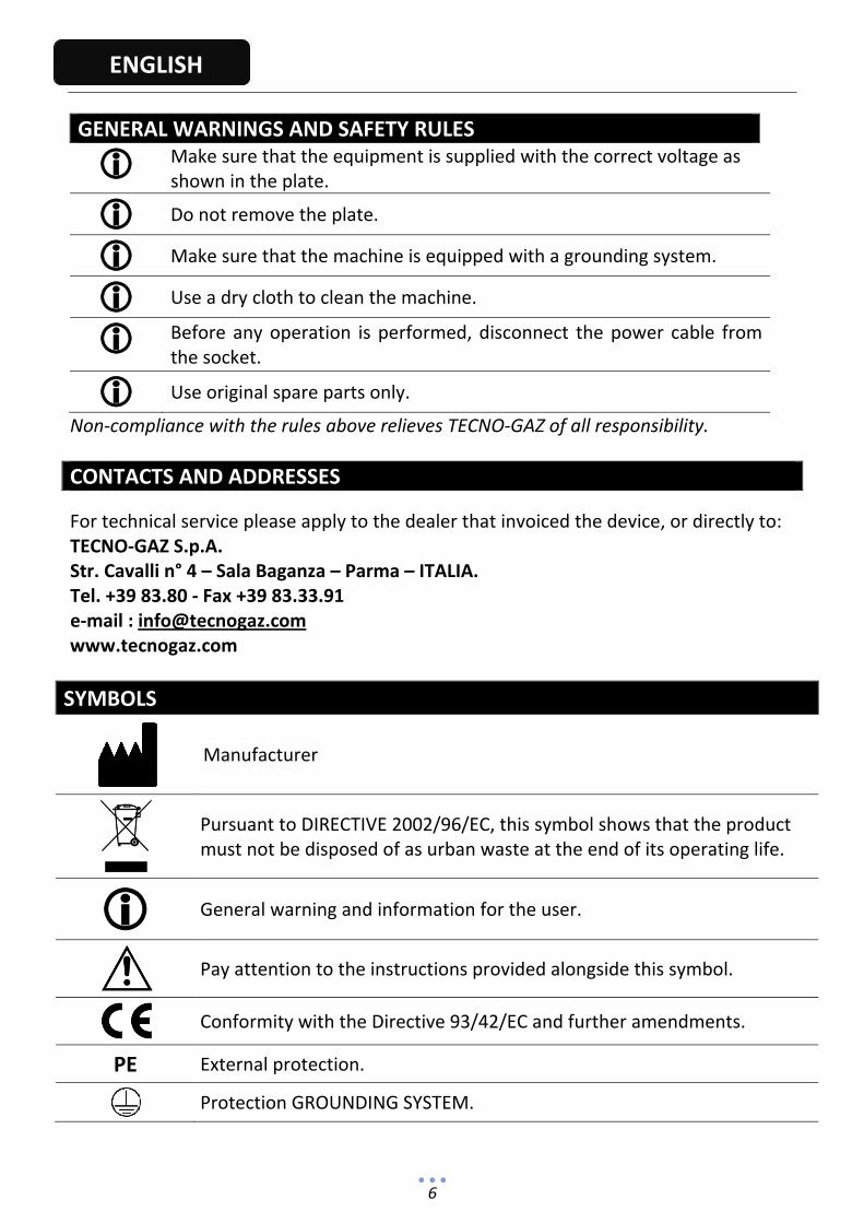
GENERAL WARNINGS AND SAFETY RULES
Make sure that the equipment is supplied with the correct voltage as shown in the plate.
Do not remove the plate.
Make sure that the machine is equipped with a grounding system.
Use a dry cloth to clean the machine.
Before any operation is performed, disconnect the power cable from the socket.
Use original spare parts only.
Non‐compliance with the rules above relieves TECNO‐GAZ of all responsibility. CONTACTS AND ADDRESSES
For technical service please apply to the dealer that invoiced the device, or directly to: TECNO‐GAZ S.p.A. Str. Cavalli n° 4 – Sala Baganza – Parma – ITALIA. Tel. +39 83.80 ‐ Fax +39 83.33.91 e‐mail : [email protected] www.tecnogaz.com
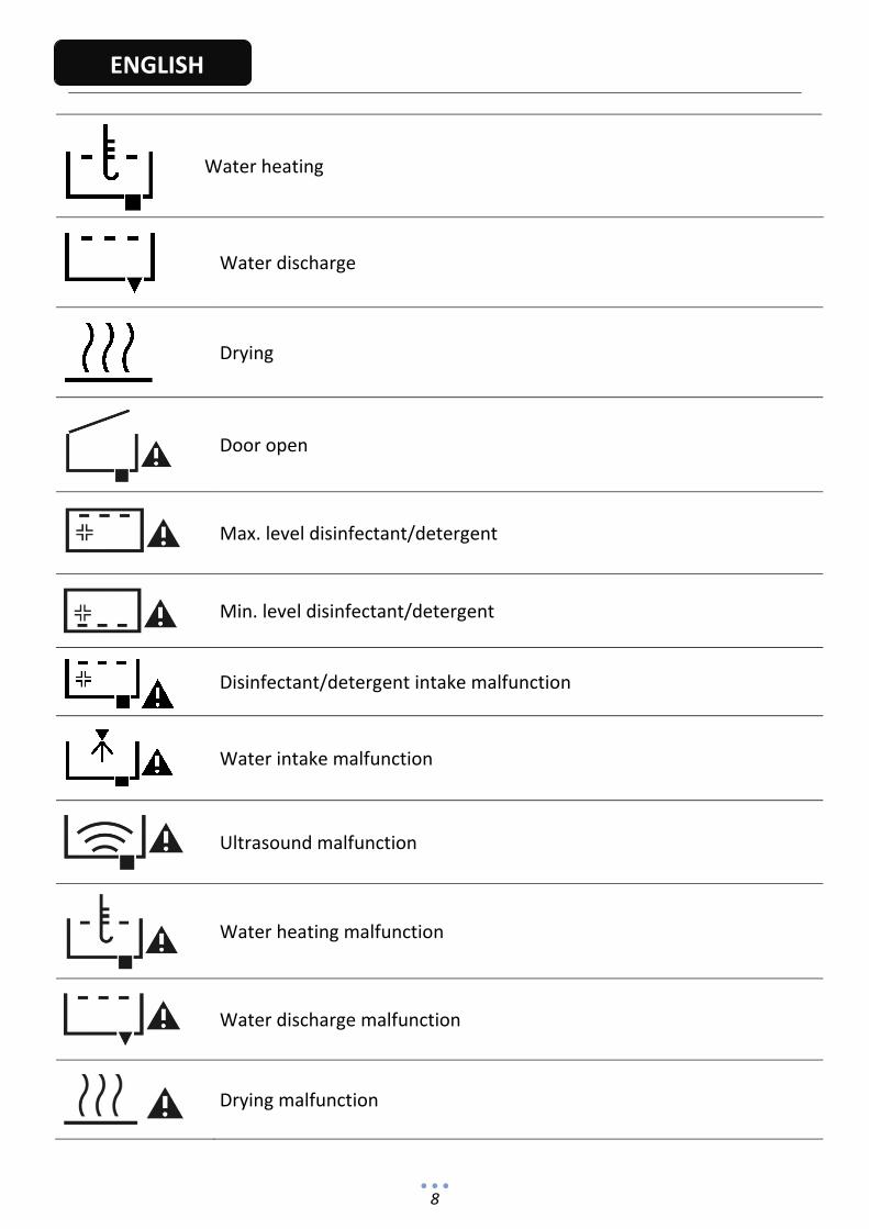
SYMBOLS
Manufacturer
Pursuant to DIRECTIVE 2002/96/EC, this symbol shows that the product must not be disposed of as urban waste at the end of its operating life.
General warning and information for the user.
Pay attention to the instructions provided alongside this symbol.
Conformity with the Directive 93/42/EC and further amendments.
PE External protection.
Protection GROUNDING SYSTEM.
7
ENGLISH
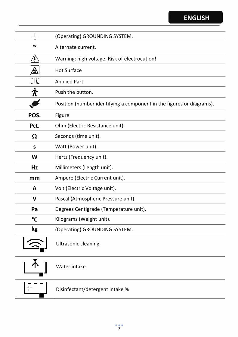
(Operating) GROUNDING SYSTEM.
~ Alternate current.
Warning: high voltage. Risk of electrocution!
Hot Surface
Applied Part
Push the button.
Position (number identifying a component in the figures or diagrams).
POS. Figure
Pct. Ohm (Electric Resistance unit).
Seconds (time unit).
s Watt (Power unit).
W Hertz (Frequency unit).
Hz Millimeters (Length unit).
mm Ampere (Electric Current unit).
A Volt (Electric Voltage unit).
V Pascal (Atmospheric Pressure unit).
Pa Degrees Centigrade (Temperature unit).
°C Kilograms (Weight unit).
kg (Operating) GROUNDING SYSTEM.
Ultrasonic cleaning
Water intake
Disinfectant/detergent intake %
8
ENGLISH
Water heating
Water discharge
Drying
Door open
Max. level disinfectant/detergent
Min. level disinfectant/detergent
Disinfectant/detergent intake malfunction
Water intake malfunction
Ultrasound malfunction
Water heating malfunction
Water discharge malfunction
Drying malfunction
9
ENGLISH
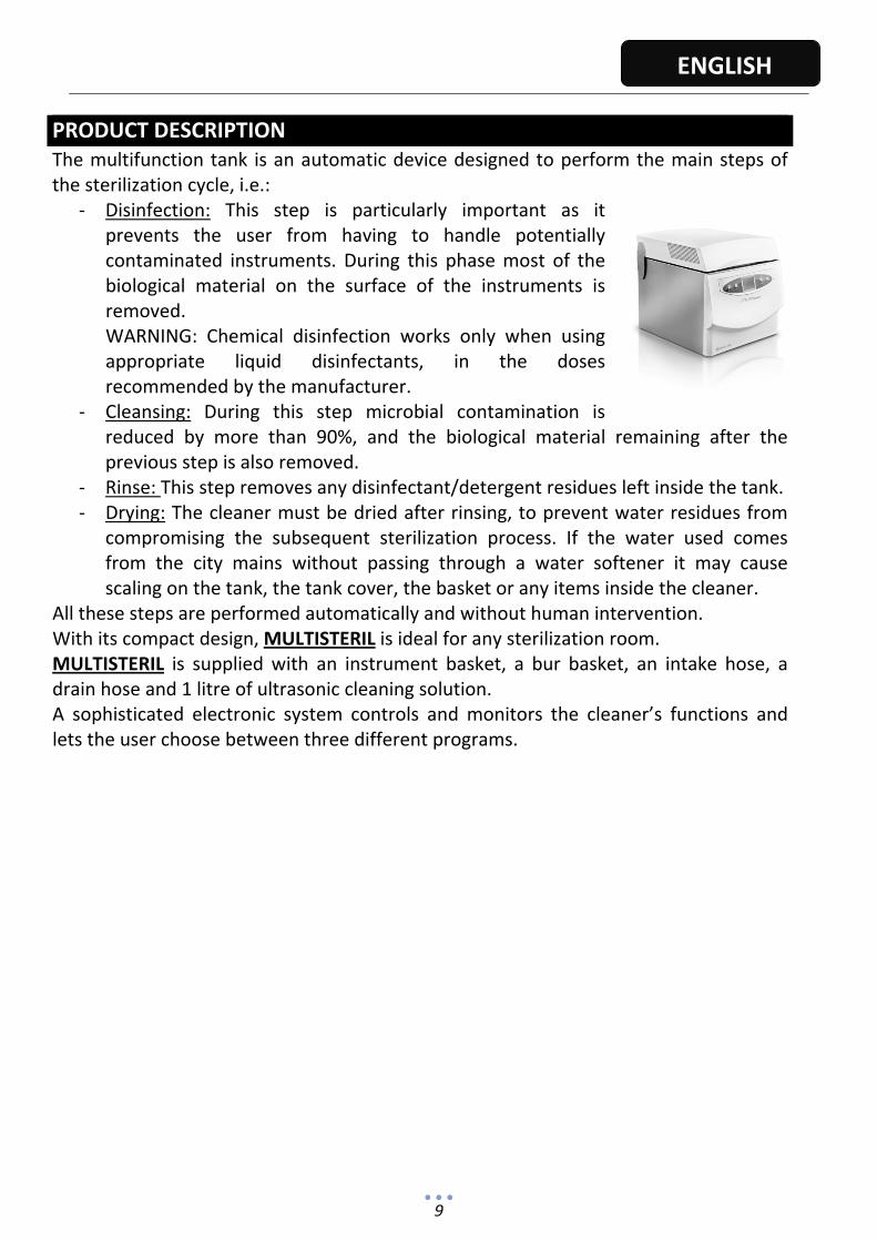
PRODUCT DESCRIPTION The multifunction tank is an automatic device designed to perform the main steps of the sterilization cycle, i.e.:
‐ Disinfection: This step is particularly important as it prevents the user from having to handle potentially contaminated instruments. During this phase most of the biological material on the surface of the instruments is removed. WARNING: Chemical disinfection works only when using appropriate liquid disinfectants, in the doses recommended by the manufacturer.
‐ Cleansing: During this step microbial contamination is reduced by more than 90%, and the biological material remaining after the previous step is also removed.
‐ Rinse: This step removes any disinfectant/detergent residues left inside the tank.‐ Drying: The cleaner must be dried after rinsing, to prevent water residues from
compromising the subsequent sterilization process. If the water used comes from the city mains without passing through a water softener it may cause scaling on the tank, the tank cover, the basket or any items inside the cleaner.
All these steps are performed automatically and without human intervention. With its compact design, MULTISTERIL is ideal for any sterilization room. MULTISTERIL is supplied with an instrument basket, a bur basket, an intake hose, a drain hose and 1 litre of ultrasonic cleaning solution. A sophisticated electronic system controls and monitors the cleaner’s functions and lets the user choose between three different programs.

10
ENGLISH
CONSTRUCTIVE SPECIFICATIONS
Dimensions (H, L, D) 415 x 415 x 450 mm
Dimensions with tank open (H, L, D) 750 x 415 x 530 mm
Weight 20 kg
Dimensions of packing (H, L, D) 520 x 545 x 590 mm
Power supply voltage 230VAC
Electric phases 1
Power supply frequency 50Hz
Max. absorbed power 1000W
Fuse 6A
Tank capacity 6 l
Transducers 4
Tank dimensions (H, L, D) 332 x 227 x 120 mm
Material ABS, Stainless Steel
Pct. 1
11
ENGLISH
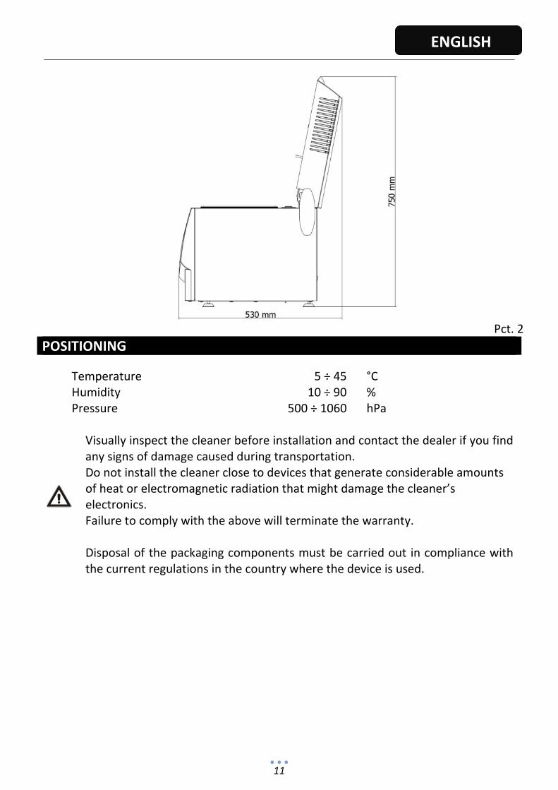
Pct. 2
POSITIONING
Temperature 5 ÷ 45 °CHumidity 10 ÷ 90 %Pressure 500 ÷ 1060 hPa
Visually inspect the cleaner before installation and contact the dealer if you find any signs of damage caused during transportation. Do not install the cleaner close to devices that generate considerable amounts of heat or electromagnetic radiation that might damage the cleaner’s electronics. Failure to comply with the above will terminate the warranty. Disposal of the packaging components must be carried out in compliance with the current regulations in the country where the device is used.

12
ENGLISH
INSTALLATION
Remove the packing and inspect the cleaner.
If you notice any signs of damage, contact the manufacturer.
Keep the packing material available for the entire duration of the warranty period. The manufacturer will not accept goods returned without the original packing.
Place the cleaner on a flat, stable surface.When drying, the cleaner releases hot air from the sides and intakes air from the back, so leave at least 5 cm of free space on the sides and the back of the cleaner during installation.
Do not install the cleaner in potentially explosive atmospheres.
Install the cleaner far from sources of heat (e.g., bunsen burners, steamers, ovens, etc.).
Install the cleaner so that the control panel and the screen can be clearly seen by the user.
Make sure the power cable is not damaged.
Transportation and handling should be carried out applying the precautions normally used for fragile goods.
Positioning the tank:
The adjustable feet make it possible to tilt the cleaner to facilitate draining the tank.
When first installed, put some water in the tank and make sure it drains rapidly.
DO NOT TILT THE TANK TOO MUCH
Connecting and commissioning the cleaner:
Electrical connections
Connect the power cable to the socket on the back of the cleaner (Pct. 3).
Make sure the supply voltage corresponds to the voltage shown on the nameplate.
Make sure the electrical system is provided with an efficient .
The machine is switched on and off by a double‐pole switch located above the power socket.

13
ENGLISH
Hydraulic connections
Remove the caps from the rear hydraulic connections (water inlet, vent and drain water tank
Intake (Pct. 3):
Connect the water intake hose (ref. CM61031, length 3 metres) to a ¾ G male valve.
Connect the other end of the hose to the ¾ G connection on the back of the cleaner.
Use the washers supplied (ref. CM50034) to make sure the connections are tight.
Pct. 3
A Filter B Discharge outlet (diameter 22 mm) C Detergent/disinfectant tank vent/discharge outlet
D Inlet connection (¾ G) E I/0 switch and power socket with fuses
Discharge (Pct. 3):
Connect the drain hose (ref. CM61032, length 0.8 ‐ 2.7 metres).
FOR THE WATER TO DRAIN PROPERLY THE HOSE MUST DROP BELOW THE CLEANER’S LEVEL.
Since the tank is emptied by gravity, the drain hose should not bend upwards to prevent pressure drops that would considerably slow down draining and increase the overall processing time. Upstream from the outlet is a filter that preserves the operation of the drain solenoid valve. Clean the filter regularly to keep the cleaner fully efficient at all times.
CLOSE THE VALVE UPSTREAM EVERY NIGHT OR WHENEVER THE CLEANER REMAINS UNUSED FOR A NUMBER OF DAYS.

14
ENGLISH
A: Schuko socket 230VAC ±10%
B: ¾ G connection
C: ref. CM61031, length 3 metres with ¾ G connection
D: Gravity discharge ref. CM61032, length 0.8 ‐ 2.7 metres
E: Power cable L = 2.5 m Ref. CE06006
Pct. 4
Filling the disinfectant/detergent tank: The disinfectant/detergent tank has a capacity of about 2 litres. Open the tank cover and remove the plug on the top of the tank (Pct. 5). Pour the liquid disinfectant/detergent into the tank (preferably using a funnel) until an acoustic/visual signal (visible on the display) indicates that the tank is full.
Use only products recommended by the manufacturer. Do not use acid solutions or strong alkaline solutions such as sodium hypochlorite.
IT'S NECESSARY TO EMPTY THE TANK BEFORE INSERT ANOTHER TYPE OF LIQUID.
IT IS ABSOLUTELY FORBIDDEN MIX THE DIFFERENT LIQUID IN THE TANK
Emptying the tank:
When the device is not doing the cycle, press and hold the button and then
subsequently push and keep pushed the button . After 5 seconds will start the peristaltic pump, and an intermittent beep will confirm that it is running. When the tank is empty the pump will turn off automatically.
At anytime you can interrupt the process by pushing the button
Pct. 5
A
B
C D
E
15
ENGLISH
DESCRIPTION OF MACHINE OPERATION
Intended use:
The multifunction tank has been designed to clean, disinfect (using suitable products) and dry instruments used in medicine, dentistry, beauty care and veterinary medicine, following the instructions provided by the manufacturer.
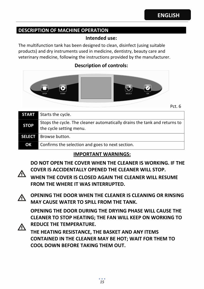
Description of controls:
Pct. 6
START Starts the cycle.
STOP Stops the cycle. The cleaner automatically drains the tank and returns to the cycle setting menu.
SELECT Browse button.
OK Confirms the selection and goes to next section.
IMPORTANT WARNINGS:
DO NOT OPEN THE COVER WHEN THE CLEANER IS WORKING. IF THE COVER IS ACCIDENTALLY OPENED THE CLEANER WILL STOP.
WHEN THE COVER IS CLOSED AGAIN THE CLEANER WILL RESUME FROM THE WHERE IT WAS INTERRUPTED.
OPENING THE DOOR WHEN THE CLEANER IS CLEANING OR RINSING MAY CAUSE WATER TO SPILL FROM THE TANK.
OPENING THE DOOR DURING THE DRYING PHASE WILL CAUSE THE CLEANER TO STOP HEATING; THE FAN WILL KEEP ON WORKING TO REDUCE THE TEMPERATURE.
THE HEATING RESISTANCE, THE BASKET AND ANY ITEMS CONTAINED IN THE CLEANER MAY BE HOT; WAIT FOR THEM TO COOL DOWN BEFORE TAKING THEM OUT.
16
ENGLISH
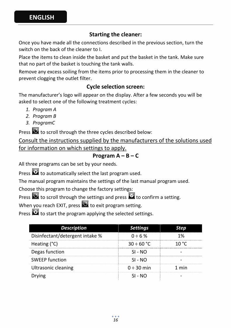
Starting the cleaner:
Once you have made all the connections described in the previous section, turn the switch on the back of the cleaner to I.
Place the items to clean inside the basket and put the basket in the tank. Make sure that no part of the basket is touching the tank walls.
Remove any excess soiling from the items prior to processing them in the cleaner to prevent clogging the outlet filter.
Cycle selection screen:
The manufacturer’s logo will appear on the display. After a few seconds you will be asked to select one of the following treatment cycles:
1. Program A 2. Program B 3. ProgramC
Press to scroll through the three cycles described below:
Consult the instructions supplied by the manufacturers of the solutions used for information on which settings to apply.
Program A – B – C
All three programs can be set by your needs.
Press to automatically select the last program used.
The manual program maintains the settings of the last manual program used.
Choose this program to change the factory settings:
Press to scroll through the settings and press to confirm a setting.
When you reach EXIT, press to exit program setting.
Press to start the program applying the selected settings.
Description Settings Step
Disinfectant/detergent intake % 0 ÷ 6 % 1%
Heating (°C) 30 ÷ 60 °C 10 °C
Degas function SI ‐ NO ‐
SWEEP function SI ‐ NO ‐
Ultrasonic cleaning 0 ÷ 30 min 1 min
Drying SI ‐ NO ‐

17
ENGLISH
The following processes are started automatically:
Water intake:
The tank takes in water through the nozzles (approx. 6 litres)
Heating:
The cleaner heats the water and performs an initial decontamination of the instruments for 5 minutes.
If the preset temperature is not reached, heating will continue during cleaning.
Disinfectant/detergent intake % and mixing the solution:
The pump inside the cleaner lets in 0.12 litres of disinfectant/detergent.
Disinfectant loading / manually detergent: *
Select "No" in the program ”Disinfectant entrance/ cleaner. Choose the
other parameters and press to start the cycle. Once the process of water loading ends the device beeps: open the door and put the disinfectant in the tank. Opening the door puts in pause the cycle until the closing.
In case of non‐opening door within 60 seconds, the device will continue the cycle with the next step.
* Procedure to be followed when you are using a liquid different from the one entered in the tank
BLINKING
Degassing:
This process removes the gases dissolved in the water.
Ultrasonic cleaning:
Cleaning by cavitation.
Discharge:
The water is discharged.
Rinse:
The cleaner rinses the instruments for few minutes to remove any trace of disinfectant/detergent.

18
ENGLISH
Drying:
The cleaner dries the instruments by blowing hot air over them to take away the humidity in the form of water vapour.
When all the above processes have been completed the cleaner emits a sound signal to inform the user.
INSTRUCTIONS FOR THE USER
DO NOT TURN OUT THE DEVICE DURING THE DRYING PHASE OR DURING THE VENTILATION. IF THE DEVICE TURN OUT DUE TO A BLACKOUT OR AN EMERGENCY CASE OPEN IMMEDIATELY THE CAP. IF THIS ADVISE IS NOT RESPECTED, THIS WILL DAMAGE THE VENTILATOR AND TO CAP OF THE DEVICE.
CLOSE THE VALVE UPSTREAM EVERY NIGHT OR WHENEVER THE CLEANER REMAINS UNUSED FOR A NUMBER OF DAYS.
DO NOT EXPOSE THE CLEANER TO FREEZING TEMPERATURES.
DO NOT INSTALL THE CLEANER CLOSE TO SOURCES OF HEAT.
DO NOT INSTALL BELOW WATER TAPS.
KEEP THE TANK AND THE COVER GASKET CLEAN.
USE DETERGENTS THAT ARE SUITABLE FOR STAINLESS STEEL.
DO NOT PERFORM MORE THAN TWO DRYING CYCLES IN A ROW.
This cleaner is intended for professional use and for the purposes described in this manual.
Setting the language:
Press for 5 seconds, then press to scroll through the available languages.
Press to confirm the selected language.
Delayed starting:
Press for 5 seconds to select the starting delay (from 0 to 12 hours). Press to go
from one value to the next, and press Start to start the treatment cycle.
During the starting delay the display will show the time remaining for the cycle to start.
WARNING: In case of power failures, delayed starting is cancelled.

19
ENGLISH
DEMOLITION AND ELIMINATION
Implementation of Directives 2002/95/EC, 2002/96/EC and 2003/108/EC on the reduced use of hazardous substances in electrical and electronic equipment, and disposal of waste
Directive on waste from electrical and electronic equipment (WEEE) Pursuant to DIRECTIVE 2002/96/EC, this symbol shows that the product must not be disposed of as urban waste at the end of its operating life. The product must be taken to centers specialized in separate collection of electric and electronic equipment or to a dealer, when a similar product is purchased. The machine holder shall be responsible for bringing it to collection centers. For further information about collection systems, address the local waste disposal service. Correct disposal of the equipment, which is no longer used, prevents negative consequences for the environment and human health. Abuses will be prosecuted by law.

20
ENGLISH
MAINTENANCE AND TROUBLESHOOTING
Cleaning: Wait for the cleaner to cool down and unplug the power cable before cleaning. To clean the device simply follow the basic sanitary rules applied when cleaning similar equipment. USE DETERGENTS THAT ARE SUITABLE FOR STAINLESS STEEL. Cleaning the inlet filter (Pct. 3): The water inlet (solenoid valve) is provided with a filter. Periodically disconnect the water intake hose and clean the filter with a cloth. Cleaning the outlet filter (Pct. 3): The filter may contain water — place a basin or a sponge beneath the filter before you take it out. Clean the filter by blowing air on it or by adding water from the inside to remove the residues on the outside. Clean the filter holder with a cloth.
A clogged filter will obstruct draining the water in the tank . If this happens,
unscrew the filter without removing it, press for 5 seconds to cancel the error message and wait for the tank to empty. Then clean the filter as described above.
Maintenance:
Changing the pump hose:
The pump hose needs to be changed periodically, at intervals depending on:
‐ Frequency of use
‐ Type of solutions used
We recommend having the hose replaced every year by qualified personnel.
Carefully follow the instructions below:
‐ Close the valve upstream every night or whenever the cleaner remains unused for
a number of days.
‐ Do not perform maintenance or repairs inside the cleaner. Disassembling the
cleaner constitutes tampering.
‐ Maintenance and repairs must be carried out only after disconnecting the
cleaner from the power and water mains.
‐ All servicing must be carried out by qualified personnel only.
21
ENGLISH
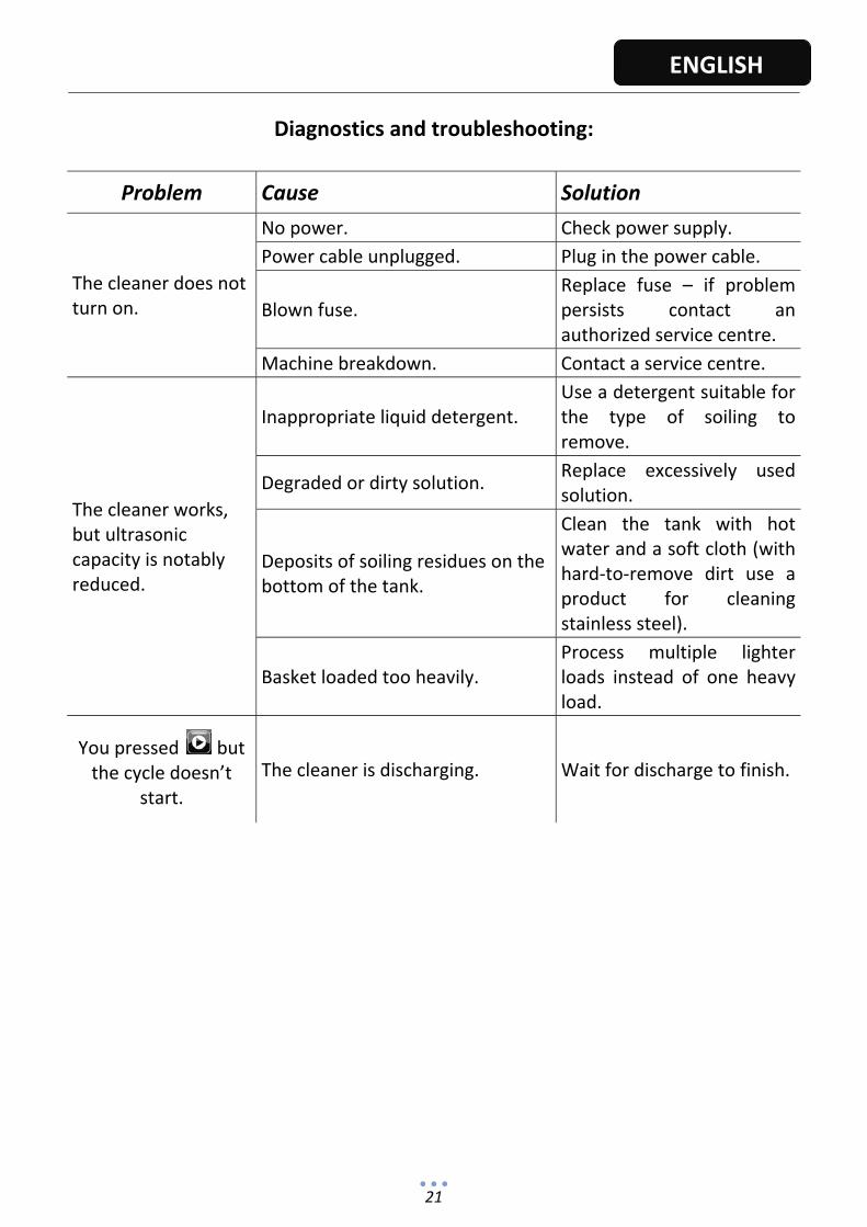
Diagnostics and troubleshooting:
Problem Cause Solution
The cleaner does not turn on.
No power. Check power supply.
Power cable unplugged. Plug in the power cable.
Blown fuse. Replace fuse – if problem persists contact an authorized service centre.
Machine breakdown. Contact a service centre.
The cleaner works, but ultrasonic capacity is notably reduced.
Inappropriate liquid detergent. Use a detergent suitable for the type of soiling to remove.
Degraded or dirty solution. Replace excessively used solution.
Deposits of soiling residues on the bottom of the tank.
Clean the tank with hot water and a soft cloth (with hard‐to‐remove dirt use a product for cleaning stainless steel).
Basket loaded too heavily. Process multiple lighter loads instead of one heavy load.
You pressed but the cycle doesn’t
start.
The cleaner is discharging. Wait for discharge to finish.

22
ENGLISH
The display shows the following symbol:
1
DOOR OPEN:
Opening the door when the cleaner is running will automatically stop the process under way.
Close the door.
2
NO DISINFECTANT/DETERGENT:
No liquid inside del tank. Fill the tank.
3
FILLING THE DISINFECTANT/DETERGENT TANK:
Add detergent/disinfectant.
4
DISINFECTANT/DETERGENT INTAKE MALFUNCTION:
Repeat the cycle after having refilled the reservoir level disinfectant.
Contact a service centre.
5
WATER INTAKE MALFUNCTION:
Check the water supply.
Check the filter on the inlet solenoid valve (see MAINTENANCE).
Contact a service centre.
6
ULTRASOUND MALFUNCTION:
Transducers malfunctioning. Contact a service centre.
23
ENGLISH
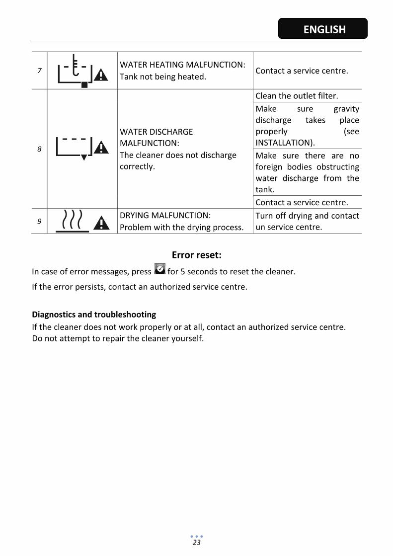
7
WATER HEATING MALFUNCTION:
Tank not being heated. Contact a service centre.
8
WATER DISCHARGE MALFUNCTION:
The cleaner does not discharge correctly.
Clean the outlet filter.
Make sure gravity discharge takes place properly (see INSTALLATION).
Make sure there are no foreign bodies obstructing water discharge from the tank.
Contact a service centre.
9
DRYING MALFUNCTION:
Problem with the drying process.
Turn off drying and contact un service centre.
Error reset:
In case of error messages, press for 5 seconds to reset the cleaner.
If the error persists, contact an authorized service centre.
Diagnostics and troubleshooting
If the cleaner does not work properly or at all, contact an authorized service centre. Do not attempt to repair the cleaner yourself.
24
ENGLISH
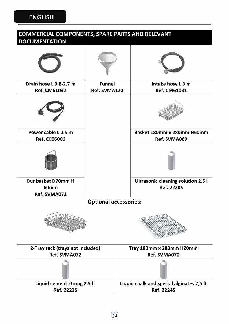
COMMERCIAL COMPONENTS, SPARE PARTS AND RELEVANT DOCUMENTATION
Drain hose L 0.8‐2.7 m Ref. CM61032
FunnelRef. SVMA120
Intake hose L 3 mRef. CM61031
Power cable L 2.5 m Ref. CE06006
Basket 180mm x 280mm H60mmRef. SVMA069
Bur basket D70mm H 60mm
Ref. SVMA072
Ultrasonic cleaning solution 2.5 lRef. 2220S
Optional accessories:
2‐Tray rack (trays not included)Ref. SVMA072
Tray 180mm x 280mm H20mmRef. SVMA070
Liquid cement strong 2,5 lt
Ref. 2222S Liquid chalk and special alginates 2,5 lt
Ref. 2224S