english videokit vk4k/3656 series - videx security · 66250454-en - v 3.4.1 - 15/09/16 2 vk4k/3656...
TRANSCRIPT
66250454-ENV 3.4.115/09/16
VIDEOKITVK4K/3656 SERIES“6 Wire” bus one way, two way videokit
Installation handbook
VK4KVK4KC
We recommendThis equipment is installed by a Competent Electrician, Security or Communications Engineer.
3656
English
66250454-EN - V 3.4.1 - 15/09/162
VK4K/3656 Series “6 wire Bus” videokit
VK4K/3656 Series - Installation handbook
Index
IntroductionThe VK4K Series is a new range of videokits that use the 4000 Series external door station and the Art. 3656 videophone.The camera / audio unit is the size of a single 4000 Series module and is available in either flush (VK4K) or surface (VK4K-S) mounting versions.As a result of using microprocessor technology in the door panel and videophone, a number of additional features have been add-ed to enhance the operation of the videokits and give greater feedback to the visitor and user.• Disability friendly, visual and acoustic signals from the door panel to inform the visitor of call status (call made, ringing, speak,
door open). • Programmable door open and conversation time.• Expandable to 4 entrance panels (requires an additional relay Art. 506N for each entrance panel).• Connections for a push to exit button.• Two methods of operating the electric lock:- 1) Dry contact relay, 2) capacitor discharge 12Vdc output.• Facility for the connection of a codelock Art. 4800M, display module Art. 4820, stand-alone proximity reader Art. 4850 or stand-
alone biometric reader Art. 4821 etc. • Programmable number of call tone rings from 2 to a maximum of 8.• Input for local door bell push button.• Programmable timed privacy function from 15 minutes to a maximum of 8 hours.• Door open status LED (additional wire required from the door to the videophone)• Up to 4 videophones can be connected in parallel, all with intercommunication facility.• Videophones can have a maximum of two additional audio telephone handsets connected in parallel.• Camera recall on all systems, with selective recall on systems with multiple entrances.• Door panel camera can be adjusted horizontally and vertically (10 degrees).
Introduction .................................................................................................................................................................................... 2System components and available versions ................................................................................................................................ 3General directions for installation ................................................................................................................................................ 5Troubleshooting guide .................................................................................................................................................................. 6Art. 4833 Speaker unit ................................................................................................................................................................... 7Art. 4800 - 4800M Digital codelock module ............................................................................................................................... 104000 Series surface and flush mounting door station installation .......................................................................................... 13Art. 3656 3.5" colour display videophone ................................................................................................................................. 153600 Series Videophone wall mounting instructions ............................................................................................................... 17Installation diagrams ................................................................................................................................................................... 18
66250454-EN - V 3.4.1 - 15/09/163
VK4K/3656 Series “6 wire Bus” videokit
VK4K/3656 Series - Installation handbook
System components and available versionsVK4K/3656 Colour videokit.
49,8
43,8
135,0
160,
0
45,0 22,5
15,7
143,
0
120,0
45,0
INDOORSTATIONVideophoneArt. 3656pag. 15
ACCESSORIESPower supplyArt. 850Kpag. 5
OUTDOORSTATION
Camera unitArt. 4833pag. 7
FlushMounting
SurfaceMounting
Fig. 1 - VK4K/3656 components
ON
E W
AY V
ERSI
ON
S
VK4K-1/3656 - flush mounting1 Outdoor stationcomposed of:1 Art. 4833-1/C: 1 button camera unit1 Art. 4851: Flush mounting box
1 Colour videophoneArt. 3656
1 Power supplyArt. 850K
VK4K-1S/3656 - surface mounting1 Outdoor stationcomposed of:1 Art. 4833-1/C: 1 button camera unit1 Art. 4881: Surface mounting box
1 Colour videophoneArt. 3656
1 Power supplyArt. 850K
TWO
WAY
VER
SIO
NS
VK4K-2/3656 - flush mounting1 Outdoor stationcomposed of:1 Art. 4833-2/C: 2 buttons camera unit1 Art. 4851: Flush mounting box
2 Colour videophonesArt. 3656
2 Power suppliesArt. 850K
VK4K-2S/3656 - surface mounting1 Outdoor stationcomposed of:1 Art. 4833-2/C: 2 buttons camera unit1 Art. 4881: Surface mounting box
2 Colour videophonesArt. 3656
2 Power suppliesArt. 850K
66250454-EN - V 3.4.1 - 15/09/164
VK4K/3656 Series “6 wire Bus” videokit
VK4K/3656 Series - Installation handbook
VK4KC/3656 Colour videokit plus a codelock module.
51,0135,0
280,
0
45,0 24,0
263,
0
INDOORSTATIONVideophoneArt. 3656pag. 15
ACCESSORIESPower supplyArt. 850Kpag. 5
OUTDOORSTATION
FlushMounting
SurfaceMounting
Camera unitArt. 4833pag. 7
CodelockunitArt. 4800Mpag. 10
Fig. 2 - VK4KC/3656 components
ON
E W
AY V
ERSI
ON
S
VK4KC-1/3656 - flush mounting1 Outdoor stationcomposed of:1 Art. 4833-1/C: 1 button camera unit1 Art. 4800M: Codelock module1 Art. 4852: Flush mounting box
1 Colour videophoneArt. 3656
1 Power supplyArt. 850K
VK4KC-1S/3656 - surface mounting1 Outdoor stationcomposed of:1 Art. 4833-1/C: 1 button camera unit1 Art. 4800M: Codelock module1 Art. 4882: Surface mounting box
1 Colour videophoneArt. 3656
1 Power supplyArt. 850K
TWO
WAY
VER
SIO
NS
VK4KC-2/3656 - flush mounting1 Outdoor stationcomposed of:1 Art. 4833-2/C: 2 buttons camera unit1 Art. 4800M: Codelock module1 Art. 4852: Flush mounting box
2 Colour videophonesArt. 3656
2 Power suppliesArt. 850K
VK4KC-2S/3656 - surface mounting1 Outdoor stationcomposed of:1 Art. 4833-2/C: 2 buttons camera unit1 Art. 4800M: Codelock module1 Art. 4882: Surface mounting box
2 Colour videophonesArt. 3656
2 Power suppliesArt. 850K
System components and available versions
66250454-EN - V 3.4.1 - 15/09/165
VK4K/3656 Series “6 wire Bus” videokit
VK4K/3656 Series - Installation handbook
General directions for installationCONNECTION TO MAINSThe system must be installed according to national rules in force, in particular we recommend to:• Connect the system to the mains through an all-pole circuit breaker which shall have contact separation of at least 3mm in each
pole and shall disconnect all poles simultaneously;• The all-pole circuit breaker shall be placed for easy access and the switch shall remain readily operable.
POWER SUPPLY INSTALLATION• Remove the terminal side covers by unscrewing the retaining screws;• Fix the power supply to a DIN bar or directly to the wall using two expansion type screws;• Switch off the mains using the circuit breaker mentioned above and then make the connections as shown on the installation diagrams;• Check the connections and secure the wires into the terminals;• Replace the terminal covers and fix them using the relevant screws;• When all connections are made, restore the mains.
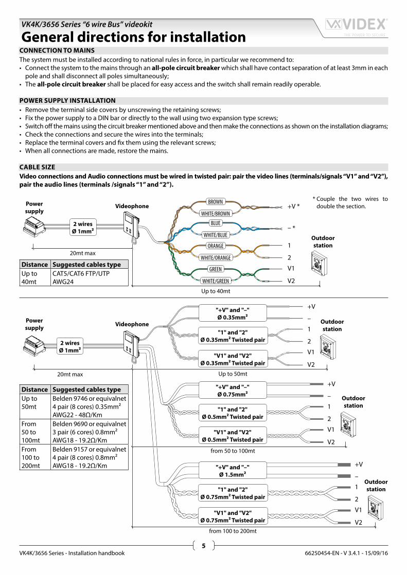
CABLE SIZEVideo connections and Audio connections must be wired in twisted pair: pair the video lines (terminals/signals “V1” and “V2”), pair the audio lines (terminals /signals “1” and “2”).
+V *
– *
1
V1
V2
2
Power supply
Videophone
Up to 40mt
2 wiresØ 1mm2
20mt max
Outdoor station
BROWN
ORANGE
BLUE
GREEN
WHITE/BROWN
WHITE/ORANGE
WHITE/BLUE
WHITE/GREEN
Distance Suggested cables typeUp to40mt
CAT5/CAT6 FTP/UTPAWG24
* Couple the two wires to double the section.
1
V1
V2
+V
–
2
1
V1
V2
+V
–
2
1
V1
V2
+V
–
2
Power supply Videophone
Up to 50mt
Outdoor station
Outdoor station
Outdoor station
"+V" and "–"Ø 0.35mm2
"V1" and "V2"Ø 0.35mm2 Twisted pair
"1" and "2"Ø 0.35mm2 Twisted pair
20mt max
2 wiresØ 1mm2
from 50 to 100mt
"+V" and "–"Ø 0.75mm2
"1" and "2"Ø 0.5mm2 Twisted pair
"V1" and "V2"Ø 0.5mm2 Twisted pair
from 100 to 200mt
"+V" and "–"Ø 1.5mm2
"V1" and "V2"Ø 0.75mm2 Twisted pair
"1" and "2"Ø 0.75mm2 Twisted pair
Distance Suggested cables typeUp to50mt
Belden 9746 or equivalnet4 pair (8 cores) 0.35mm2AWG22 - 48Ω/Km
From50 to 100mt
Belden 9690 or equivalnet3 pair (6 cores) 0.8mm2AWG18 - 19.2Ω/Km
From100 to 200mt
Belden 9157 or equivalnet4 pair (8 cores) 0.8mm2AWG18 - 19.2Ω/Km
66250454-EN - V 3.4.1 - 15/09/166
VK4K/3656 Series “6 wire Bus” videokit
VK4K/3656 Series - Installation handbook
In case of system failure, try the following preliminary checks:• Check that the cables are connected as shown in the installation diagram and that the cables are firmly fixed into the relevant terminals;• Check that the mains voltage is available on terminals 230Vac (or 127Vac) and 0 of the power transformer Art. 850K;• Check the 24Vac voltage output of the power transformer Art. 850K. If this voltage is not available it could be the 1,6A fuse, in this case
remove the mains voltage, remove possible short-circuits or overload sources then replace the fuse with an equal or equivalent one.• Check that the voltage between the terminals “+” and “-” of the speaker unit is between 16 and 20Vdc.If the problem persists try the tests in the following table or contact technical support.
SYMPTOM CAUSE SOLUTIONThe door station is not able to call the ex-tension (the bell LED is switched on for 2 seconds):
• Wrong connection between door sta-tion and the videophone
• Cable size too small.• Programmed videophone address in-
correct.• You have changed the videophone ad-
dress without power down the system.
• Check the 6 common wire connections especially wire “1” (speech line/data).
• Increase cable size or double up using two wires for each connection.
• Check videophone address on dip-swi-tches.
• Power down the system then power up again to detect the new videophone ad-dress.
External call works but when answered the communication fails:
• Cable size too small. • Increase cable size or double up using two wires for each signal.
During the conversation it is not possible to open the door:
• Cable size too small. • Increase cable size or double up using two wires for each signal.
During the conversation it is not possible to open the door but the key LED on the door station switches on for the program-med time:
• Incorrect position of J2 jumper.• Electric lock wires unconnected or in short.• Wrong electric lock type.
• Check J2 position on the door station.• Check connection.• Check that the electric lock type (ac or dc)
is suitable for the J2 position chosen.Speech only from outside to inside: • Wire “2” broken or in short. • Check connection of wire “2”.Low volume of speech: • Volume trimmers of door station require
adjustment.• Adjust the trimmers until the required
volume is reached.Noise over the speech line during the con-versation:
• The 6 common wires are cabled to-gether with 230 or 380Vac power lines.
• The 6 common wires are cabled to-gether with 24Vac videophone power supply wires.
• Separate the 6 common wires from the high voltages cables.
• Separate the 6 common wires from the two 24Vac wires or cable them together only for a short distance.
Camera recall service does not work: • Camera recall button pressed for a num-ber of times different from the ID of the door station to be switched on.
• Check the ID (1..4) of the door station to be recalled and press the camera recall but-ton as many time as the ID value.
Intercommunicating call does not work: • ”Key” button pressed for a number of times different from the videophone ad-dress value.
• Check the address of the videophone you are calling and try again.
The video shown on the monitor is of a bad quality and the image is distorted or double
• V1,V2 signals unconnected, reversed or shorted.
• The switches of the two way dip-switch are not both in ON position.
• V1,V2 of the last Art. 316N (if present) not closed with 75 Ohm resistor.
• Check that the wires are not broken or shorted.
• Set both switches to the ON position.• Use 2x 75 Ohm resistors to connect V1
& V2 to 0V.
Local call does not work: • Wrong connection or call button broken. • Check connection or replace the button.
Troubleshooting guide
66250454-EN - V 3.4.1 - 15/09/167
VK4K/3656 Series “6 wire Bus” videokit
VK4K/3656 Series - Installation handbook
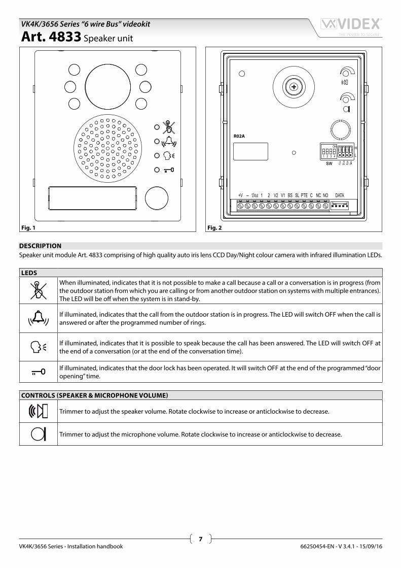
Art. 4833 Speaker unit
Fig. 1
sw
NONCCPTESLBSV1V22112Vout-+V
J1 J2 J3 J41 2 3 4
ON
DATA
HL
R02A
Fig. 2
DESCRIPTIONSpeaker unit module Art. 4833 comprising of high quality auto iris lens CCD Day/Night colour camera with infrared illumination LEDs.
LEDSWhen illuminated, indicates that it is not possible to make a call because a call or a conversation is in progress (from the outdoor station from which you are calling or from another outdoor station on systems with multiple entrances). The LED will be off when the system is in stand-by.
If illuminated, indicates that the call from the outdoor station is in progress. The LED will switch OFF when the call is answered or after the programmed number of rings.
If illuminated, indicates that it is possible to speak because the call has been answered. The LED will switch OFF at the end of a conversation (or at the end of the conversation time).
If illuminated, indicates that the door lock has been operated. It will switch OFF at the end of the programmed “door opening” time.
CONTROLS (SPEAKER & MICROPHONE VOLUME)
Trimmer to adjust the speaker volume. Rotate clockwise to increase or anticlockwise to decrease.
Trimmer to adjust the microphone volume. Rotate clockwise to increase or anticlockwise to decrease.
66250454-EN - V 3.4.1 - 15/09/168
VK4K/3656 Series “6 wire Bus” videokit
VK4K/3656 Series - Installation handbook
Art. 4833 Speaker unit
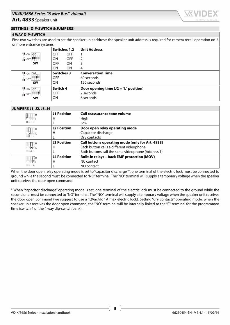
SETTINGS (DIP-SWITCH & JUMPERS)
4 WAY DIP-SWITCHFirst two switches are used to set the speaker unit address: the speaker unit address is required for camera recall operation on 2 or more entrance systems.
SW
Switches 1,2 Unit AddressOFF OFF 1ON OFF 2OFF ON 3ON ON 4
SW
Switches 3 Conversation TimeOFF 60 secondsON 120 seconds
SW
Switch 4 Door opening time (J2 = “L” position)OFF 2 secondsON 6 seconds
JUMPERS J1, J2, J3, J4H
LJ2 J3 J4J1
J1 Position Call reassurance tone volumeH HighL Low
H
LJ1 J2 J3 J4
J2 Position Door open relay operating modeH Capacitor dischargeL Dry contacts
H
LJ1 J2 J3 J4
J3 Position Call buttons operating mode (only for Art. 4833)H Each button calls a different videophoneL Both buttons call the same videophone (Address 1)
H
LJ1 J2 J3 J4
J4 Position Built-in relays – back EMF protection (MOV)H NC contactL NO contact
When the door open relay operating mode is set to “capacitor discharge”*, one terminal of the electric lock must be connected to ground while the second must be connected to “NO” terminal. The “NO” terminal will supply a temporary voltage when the speaker unit receives the door open command.
* When “capacitor discharge” operating mode is set, one terminal of the electric lock must be connected to the ground while the second one must be connected to “NO” terminal. The “NO” terminal will supply a temporary voltage when the speaker unit receives the door open command (we suggest to use a 12Vac/dc 1A max electric lock). Setting “dry contacts” operating mode, when the speaker unit receives the door open command, the “NO” terminal will be internally linked to the “C” terminal for the programmed time (switch 4 of the 4 way dip-switch bank).
66250454-EN - V 3.4.1 - 15/09/169
VK4K/3656 Series “6 wire Bus” videokit
VK4K/3656 Series - Installation handbook
Art. 4833 Speaker unit
BUILT-IN RELAYS – BACK EMF PROTECTIONThe Art. 4833 includes selectable back EMF protection on the relays. The jumpers marked J4 (One jumper for each relay) are used to select the protection type. When using a fail secure lock with connections C & NO the jumper should be in the NO position. When using a fail open lock with connections C & NC the jumper should be in the NC position and when using the codelock to trigger a gate con-troller or another third party controller the jumper should be removed completely (This disables the protection on the relay).
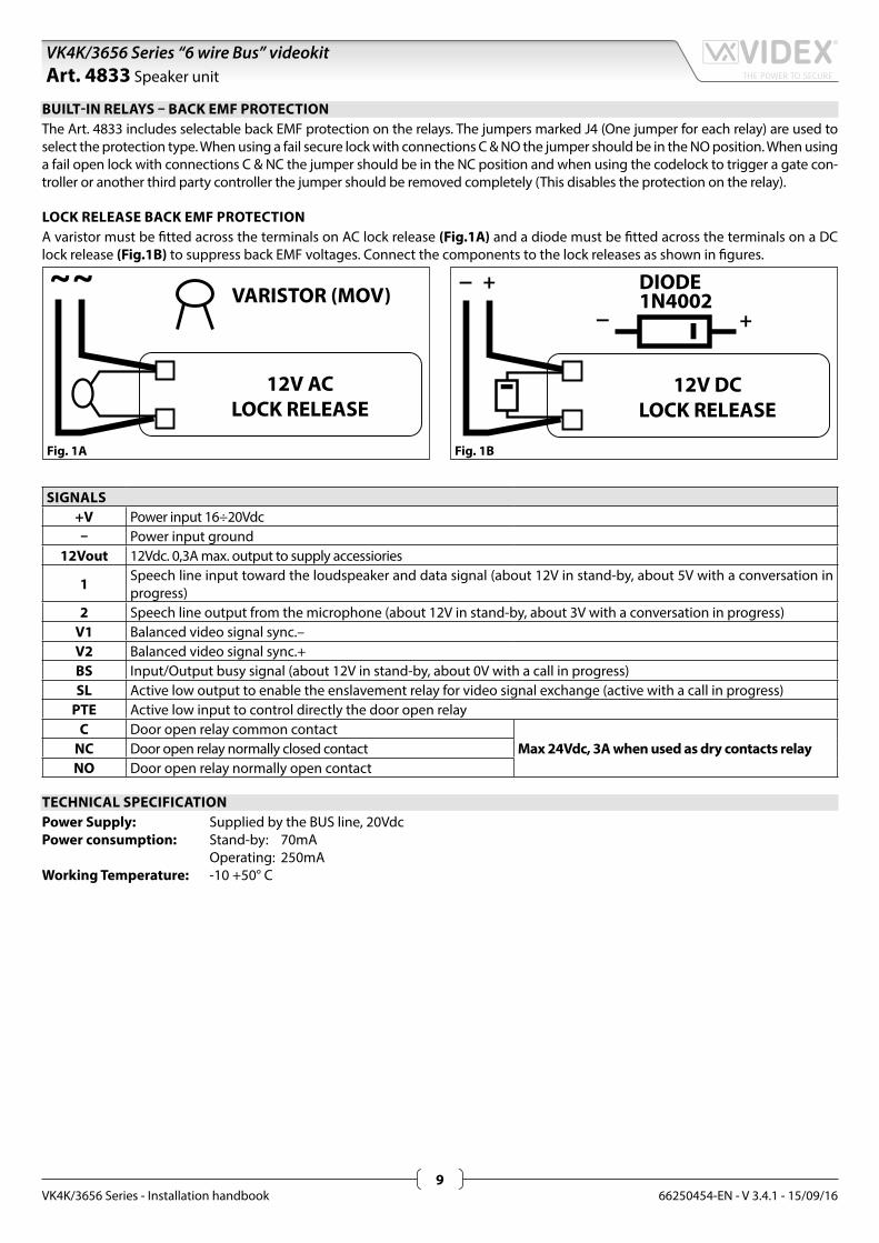
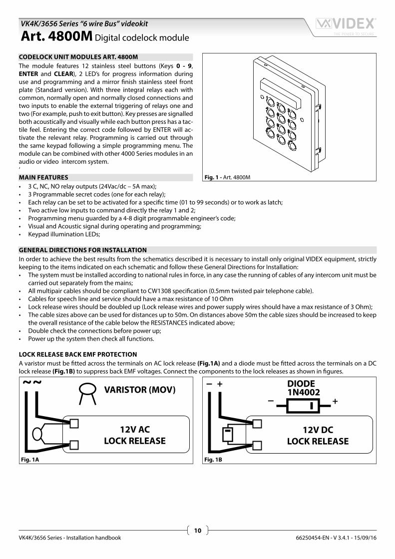
LOCK RELEASE BACK EMF PROTECTIONA varistor must be fi tted across the terminals on AC lock release (Fig.1A) and a diode must be fi tted across the terminals on a DC lock release (Fig.1B) to suppress back EMF voltages. Connect the components to the lock releases as shown in fi gures.
VARISTOR (MOV)
12V ACLOCK RELEASE
Fig. 1A
DIODE1N4002
12V DCLOCK RELEASE
Fig. 1B
SIGNALS+V Power input 16÷20Vdc– Power input ground
12Vout 12Vdc. 0,3A max. output to supply accessiories
1 Speech line input toward the loudspeaker and data signal (about 12V in stand-by, about 5V with a conversation in progress)
2 Speech line output from the microphone (about 12V in stand-by, about 3V with a conversation in progress)V1 Balanced video signal sync.–V2 Balanced video signal sync.+BS Input/Output busy signal (about 12V in stand-by, about 0V with a call in progress)SL Active low output to enable the enslavement relay for video signal exchange (active with a call in progress)
PTE Active low input to control directly the door open relayC Door open relay common contact
Max 24Vdc, 3A when used as dry contacts relayNC Door open relay normally closed contactNO Door open relay normally open contact
TECHNICAL SPECIFICATIONPower Supply: Supplied by the BUS line, 20VdcPower consumption: Stand-by: 70mA Operating: 250mAWorking Temperature: -10 +50° C
66250454-EN - V 3.4.1 - 15/09/1610
VK4K/3656 Series “6 wire Bus” videokit
VK4K/3656 Series - Installation handbook
Art. 4800M Digital codelock module
CODELOCK UNIT MODULES ART. 4800MThe module features 12 stainless steel buttons (Keys 0 - 9, ENTER and CLEAR), 2 LED’s for progress information during use and programming and a mirror finish stainless steel front plate (Standard version). With three integral relays each with common, normally open and normally closed connections and two inputs to enable the external triggering of relays one and two (For example, push to exit button). Key presses are signalled both acoustically and visually while each button press has a tac-tile feel. Entering the correct code followed by ENTER will ac-tivate the relevant relay. Programming is carried out through the same keypad following a simple programming menu. The module can be combined with other 4000 Series modules in an audio or video intercom system.‘MAIN FEATURES• 3 C, NC, NO relay outputs (24Vac/dc – 5A max);• 3 Programmable secret codes (one for each relay);• Each relay can be set to be activated for a specific time (01 to 99 seconds) or to work as latch;• Two active low inputs to command directly the relay 1 and 2;• Programming menu guarded by a 4-8 digit programmable engineer’s code;• Visual and Acoustic signal during operating and programming;• Keypad illumination LEDs;
GENERAL DIRECTIONS FOR INSTALLATIONIn order to achieve the best results from the schematics described it is necessary to install only original VIDEX equipment, strictly keeping to the items indicated on each schematic and follow these General Directions for Installation:• The system must be installed according to national rules in force, in any case the running of cables of any intercom unit must be
carried out separately from the mains;• All multipair cables should be compliant to CW1308 specification (0.5mm twisted pair telephone cable).• Cables for speech line and service should have a max resistance of 10 Ohm• Lock release wires should be doubled up (Lock release wires and power supply wires should have a max resistance of 3 Ohm);• The cable sizes above can be used for distances up to 50m. On distances above 50m the cable sizes should be increased to keep
the overall resistance of the cable below the RESISTANCES indicated above;• Double check the connections before power up;• Power up the system then check all functions.
LOCK RELEASE BACK EMF PROTECTIONA varistor must be fi tted across the terminals on AC lock release (Fig.1A) and a diode must be fi tted across the terminals on a DC lock release (Fig.1B) to suppress back EMF voltages. Connect the components to the lock releases as shown in fi gures.
VARISTOR (MOV)
12V ACLOCK RELEASE
Fig. 1A
DIODE1N4002
12V DCLOCK RELEASE
Fig. 1B
Fig. 1 - Art. 4800M

66250454-EN - V 3.4.1 - 15/09/1611
VK4K/3656 Series “6 wire Bus” videokit
VK4K/3656 Series - Installation handbook
BUZZER BACK EMFWhen using intercoms with buzzer call (Art.924/926, SMART1/2, 3101/2, 3001/2 and 3021/2) add one 0.1uF (100nF) capacitor be-tween terminals 3 and 6 on the telephone.
BUILT-IN RELAYS – BACK EMF PROTECTIONThe Art. 4800M includes selectable back EMF protection on the relays. The jumpers marked MOV (One jumper for each relay) are used to select the protection type. When using a fail secure lock with connections C & NO the jumper should be in the NO position. When using a fail open lock with connections C & NC the jumper should be in the NC position and when using the codelock to trigger a gate controller or another third party controller the jumper should be removed completely (This disables the protection on the relay).
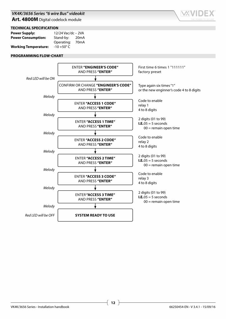
PROGRAMMING (SEE ALSO THE RELEVANT FLOW CHART)• Enter the “ENGINEER’S CODE”: first time type six times “1” (111111 factory preset) and press “ENTER” (The red LED will illuminate);• Confirm “ENGINEER’S CODE” (typing again the same) or type the new code (4 to 8 digits) then press “ENTER” (Melody). Pressing
twice the “ENTER” button without changing the “ENGINEER’S CODE”, will exit from the programming;• Enter the code (4 to 8 digits) to enable “RELAY 1” or re-enter the existing code then press “ENTER” (Melody);• Enter the “RELAY 1” operation time (2 digits 01 to 99 I.E. 05=5 seconds, 00= remain open time) or re-enter the existing time then
press “ENTER” (Melody);• Enter the code (4 to 8 digits) to enable “RELAY 2” or re-enter the existing code then press “ENTER” (Melody);• Enter the “RELAY 2” operation time (2 digits 01 to 99 I.E. 05=5 seconds, 00= remain open time) or re-enter the existing time then
press “ENTER” (Melody);• Enter the code (4 to 8 digits) to enable “RELAY 3” or re-enter the existing code then press “ENTER” (Melody);• Enter the “RELAY 3” operation time (2 digits 01 to 99 I.E. 05=5 seconds, 00= remain open time) or re-enter the existing time then
press “ENTER” (Melody);• The system is ready to use (the red LED will be off).
PROGRAMMING NOTES• After pressing enter following a command, press “ENTER” a further twice to exit the programming menu.
RETURN SYSTEM TO PRESET ENGINEER’S FACTORY CODE• Turn off power to code lock;• Keep “ENTER” button pressed while turning the power back on;• Release “ENTER” button;• The engineer’s code is now set to “111111” (six times one).
OPERATION• Type in the programmed code and press “ENTER”;• If the code is correct, the green LED will illuminate for ap-
prox. 2 seconds and the relay relevant to the code will oper-ate for the programmed time;
• If a wrong code is entered, a continuous melody will sound for 4 or more seconds, according to the number of mistakes;
• To switch off any relay while operating, type in the relevant code then press the “CLEAR” button;
OPERATION NOTES• To operate relays together, set the same code for each relay;• If a wrong code is entered, the system will lock out for 5 sec-
onds which will increase each time a wrong code is entered. The system will operate only when the correct code is entered.
TERMINALS:SW2 Relay 2 command signal (active low)SW1 Relay 1 command signal (active low)NC3 Relay 3 normally closed contact
Max24Vac/dc
3A
NO3 Relay 3 normally open contact C3 Relay 3 common contactNC2 Relay 2 normally closed contact NO2 Relay 2 normally open contact C2 Relay 2 common contactNC1 Relay 1 normally closed contact NO1 Relay 1 normally open contact C1 Relay 1 common contact–
12/24Vac/dc power input+
Art. 4800M Digital codelock module
66250454-EN - V 3.4.1 - 15/09/1612
VK4K/3656 Series “6 wire Bus” videokit
VK4K/3656 Series - Installation handbook
TECHNICAL SPECIFICATIONPower Supply: 12/24 Vac/dc – 2VAPower Consumption: Stand-by: 20mA Operating: 70mAWorking Temperature: -10 +50° C
PROGRAMMING FLOW-CHART
ENTER “ENGINEER’S CODE“AND PRESS “ENTER“
CONFIRM OR CHANGE “ENGINEER’S CODE“AND PRESS “ENTER“
ENTER “ACCESS 1 CODE“AND PRESS “ENTER“
ENTER “ACCESS 1 TIME“AND PRESS “ENTER“
ENTER “ACCESS 2 CODE“AND PRESS “ENTER“
ENTER “ACCESS 2 TIME“AND PRESS “ENTER“
ENTER “ACCESS 3 CODE“AND PRESS “ENTER“
ENTER “ACCESS 3 TIME“AND PRESS “ENTER“
SYSTEM READY TO USE
First time 6 times 1 "111111"factory preset
Type again six times “1”or the new enginner’s code 4 to 8 digits
Code to enablerelay 14 to 8 digits
Code to enablerelay 24 to 8 digits
2 digits (01 to 99)I.E. 05 = 5 seconds 00 = remain open time
2 digits (01 to 99)I.E. 05 = 5 seconds 00 = remain open time
Code to enablerelay 34 to 8 digits
2 digits (01 to 99)I.E. 05 = 5 seconds 00 = remain open time
Red LED will be ON
Red LED will be OFF
Melody
Melody
Melody
Melody
Melody
Melody
Melody
Art. 4800M Digital codelock module

66250454-EN - V 3.4.1 - 15/09/1613
VK4K/3656 Series “6 wire Bus” videokit
VK4K/3656 Series - Installation handbook
4000 Series Surface and flush mounting door station installation
H
G
H
Y
G
C
F
ED
BA
C L
H
L
P O
N
MH
M
M
C
Q
P
C
D
W
N
N
C
H
fig. 1
fig. 8
fig. 4 fig. 5 fig. 6 fig. 7
fig. 3
fig. 10
fig. 11
fig. 15
fig. 12
fig. 16
fig. 13
fig. 17
fig. 14
fig. 18
fig. 2
fig. 9
EXAMPLE: INSTALLING A FOUR MODULE OUTDOOR STATION
66250454-EN - V 3.4.1 - 15/09/1614
VK4K/3656 Series “6 wire Bus” videokit
VK4K/3656 Series - Installation handbook
4000 Series Surface and flush mounting door station installation
INSTALLING A SURFACE MOUNT DOOR STATION1. Place the surface box against the wall (165-170cm between the top of the box and the floor level as shown in Fig. 1) and mark the
fixing holes for the wall plugs and the hole for the cables E (fig. 2). Observe the orientation of the box with the hinge on the left;
In order to prevent water ingress we highly recommend using a silicon sealant between the wall and the back box C (Fig.3) and around all holes D (Fig.3);
2. As shown on Fig. 2, drill the fixing holes A, insert the wall plugs B and feed the cables E through the surface box opening D, fix surface box C to the wall using the screws F;
3. Apply the Y silicon sealant on top of each module as shown in Fig. 4;4. Before installation of the module support frame, hook the modules G to the support frame H as shown in Fig. 5 then, as shown
in Fig. 6, fit the two anti-tampering locks W for each module (do the same for the second module support frame);5. When you have more than one support frame, hook the support frame to the surface box starting from the left. For convenience we
will described how to attach the left frame but the same must be carried out for the right frame. As shown in Fig. 7, hook the module support frame H (complete with modules) to the surface box C moving the frame as suggested from pointers. Ensure that the pivots L (Fig. 7) go inside the relevant housing M as shown in Fig. 8;
6. As shown on Fig. 9, pull back the module support frame H while moving it slightly to the left as suggested by the pointers;7. As shown in Fig. 10, open the module support frame H as suggested by the pointer, hook the hinge locks N to the hinges M,
make the required connections using the screwdriver provided P (flat blade end) and make the required adjustment by adjust-ing the settings (through openings O) and adjust trimmers;
8. Repeat the same operations described above for the second module support frame (or for the third if available);9. When the system has been tested and is working correctly, move back the module support frames carefully, fix them to the surface
box using the screwdriver provided P (torx end) and the pin machine torx screws Q (Fig. 11). Note: do not over tighten the screws more than is necessary.
INSTALLING A FLUSH MOUNTING DOOR STATIONWhen flush mounting and the number of modules is greater than 3, the required back boxes need to be linked together (before embedding them in the wall) as shown on Fig. 14, 15 and 16:• Arrange the back boxes and remove knockouts to allow cables to be fed from one back box to the other;• Hook the spacers to first back box then hook the second back box to obtain the result shown on Fig. 16;1. Protect the module support frame fixing holes from dust then embed the back box into the wall (165-170cm between the top
of the box and the floor level as shown on the Fig. 1) feeding the cables E (Fig. 2) through a previously opened hole in the box. Observe the direction of the box ensuring the hinge is on the left and take care that the box profile is in line with the finished wall profile;
In order to prevent water ingress we highly recommend using a silicon sealant between the wall and the back box H (Fig.12);
2. Continue from step 4 of surface mounting instructions , but at step 7 hook the hinge locks N as shown on Fig. 13.
Note: if additional holes are made in the surface box, oxidation problems may appear unless the unprotected metal is coated with a protective paint.
NOTES• The screwdriver’s blade has two sides, one flat and one torx, to select one of them unplug the blade from the screwdriver body
and plug it into the required side.• The example shows the use of only one back box bottom hole for wires, this is done to keep file drawings clear. Naturally the
installer can use the left hole or the right or both if required.
HOW TO REMOVE THE CARD NAME HOLDER• To avoid damage to the module front plate, tape the side that will be in contact with the screwdriver blade;• lnsert the screwdriver (flat side) into the card-holder hole as shown in Fig. 17;• Move the screwdriver to the left as shown in Fig. 18 to extract the card name holder;• Edit the card name then replace it inside the holder and refit: insert the holder inside its housing from the left or right side then
push the other side until it clips into place.
66250454-EN - V 3.4.1 - 15/09/1615
VK4K/3656 Series “6 wire Bus” videokit
VK4K/3656 Series - Installation handbook
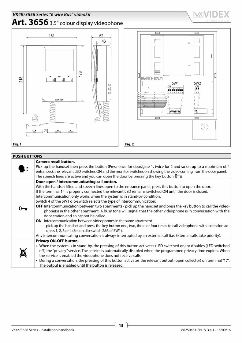
161
178
218
6246
Fig. 1
1 2
ONSW2
6 7 81 2 3 54
ONSW1
Fig. 2
PUSH BUTTONSCamera recall button.Pick up the handset then press the button (Press once for door/gate 1, twice for 2 and so on up to a maximum of 4 entrances): the relevant LED switches ON and the monitor switches on showing the video coming from the door panel.The speech lines are active and you can open the door by pressing the key button .Door-open / intercommunicating call button.With the handset lifted and speech lines open to the entrance panel, press this button to open the door.If the terminal 14 is properly connected the relevant LED remains switched ON until the door is closed.Intercommunication only works when the system is in stand-by condition.Switch 4 of the SW1 dip-switch selects the type of intercommunication:OFF Intercommunication between two apartments - pick up the handset and press the key button to call the video-
phone(s) in the other apartment. A busy tone will signal that the other videophone is in conversation with the door station and so cannot be called.
ON Intercommunication between videophones in the same apartment- pick up the handset and press the key button one, two, three or four times to call videophone with extension ad-
dress 1, 2, 3 or 4 (Set on dip-switch 2&3 of SW1).Any intercommunicating conversation is always interrupted by an external call (i.e. External calls take priority).Privacy ON-OFF button.• When the system is in stand-by, the pressing of this button activates (LED switched on) or disables (LED switched
off) the “privacy” service. The service is automatically disabled when the programmed privacy time expires. When the service is enabled the videophone does not receive calls.
• During a conversation, the pressing of this button activates the relevant output (open collector) on terminal “17”. The output is enabled until the button is released.
Art. 3656 3.5" colour display videophone

66250454-EN - V 3.4.1 - 15/09/1616
VK4K/3656 Series “6 wire Bus” videokit
VK4K/3656 Series - Installation handbook
LEDSON LED.Switched ON when the videophone is operating.Door open LED.Can be used to indicate the status of a door or gate. It requires a switched 12Vdc connection to terminal 14.Privacy ON/OFF LED.• When the videophone is in stand-by, this LED signals
the privacy service status (ON = service enabled, OFF = service disabled);
• When the videophone is active, this LED indicates the activation of the output on terminal 17.
CONTROLSCall tone volume control (3 levels).
Hue control.
Brightness control.
SETTINGS (DIP-SWITCH)The videophone setup is carried out by the 2 dip-switches ac-cessible from the rear of the videophone.
Switches 1 Apartment AddressOFF 1ON 2Switches 2,3 Extension AddressOFF OFF 1ON OFF 2OFF ON 3ON ON 4Switch 4 IntercommunicationOFF Between videophones of
the two apartmentON Between videophones in
the same apartmentSwitches 5,6 Number of ringsOFF OFF 2ON OFF 4OFF ON 6ON ON 8Switches 7,8 Privacy duration timeOFF OFF 15 minutesON OFF 1 hoursOFF ON 4 hoursON ON 8 hours
2 WAY DIP-SWITCH (SW2)The two way dip-switch adjusts the imped-ance of the video signal. The default setting is “ON” for both switches (75 Ohm): when
there are more videophones in parallel connection (without video distributor) both switches must be “ON” only on the last videophone (looking at the connection order) while for all other videophones both switches must be set to “OFF”.
3600-5000 SERIES COMPATIBILITYThe Art. 3656 videophone is fully compatible with the Art. 3356, Art. 3456 and the Art. SL5456. All primary connections are the same but spare buttons and LED connections are different de-pending on the availability of these services on that model of videophone.
TECHNICAL SPECIFICATIONPower Supply: Supplied by the BUS line, 20VdcWorking Temperature: -10 +50 °C
SIGNALS ON CONNECTION BOARD1 Speech line output from handset’s microphone and data signal (About 12V in stand-by, about 5V in conversation)2 Speech line input toward the handset’s loudspeaker (About 12V in stand-by, about 3V in conversation)3 Speech line input toward the loudspeaker of the parallel telephone (About 12V in stand-by, about 3V in conversation)4 Balanced video signal 1 sync. –5 Balanced video signal 2 sync. +6 Ground78 20Vdc Input/Output (As input 16÷20Vdc 0,5A – as output 20Vdc 0,5A max)9 24Vac 1A max power input
10 0Vac power input11 Output ground for parallel telephone12 Output call tone for parallel telephone13 Input for door-open command from parallel telephone14 12Vdc input for door-open LED15 Local call input (5V in standby, 0V to trigger)1617 Service button (open collector) active low output. The button goes active when the button is pressed during a conversation
Art. 3656 3.5" colour display videophone
66250454-EN - V 3.4.1 - 15/09/1617
VK4K/3656 Series “6 wire Bus” videokit
VK4K/3656 Series - Installation handbook
B
E
C
D
C
A
G
FFig. 2
3600 Series Videophone wall mounting instructions
135c
m
Fig. 1
B
E
C
D
C
A
G
F
Fig. 3
CML
H
I
M
Fig. 4
N
N
Fig. 5
1. Cables must be fed through the opening E (Fig. 2) of the mounting plate C, which should be fitted approximately 135cm from finished floor level as shown in Fig. 1;
2. Place the mounting plate C against the wall feeding the wire group D through opening E of the mounting plate and mark the fixing holes A (Fig. 2);
3. Drill the fixing holes A, insert the wall plugs B then with the cables threaded through opening E fix the mounting plate C to the wall with the 4 screws provided F (Fig. 2);
4. Hook the PBC connection board G to the mounting plate C as shown in Fig. 3 and connect the wires (using the screwdriver provided) to the terminals as shown in the diagram provided;
5. Once the wires are connected, hook the videophone H to the mounting plate C as shown in Fig. 3;6. Connect the Plug I on the ribbon cable from the videophone to the plug L on the PCB connection board G;7. Place the videophone H against the 4 hooks M on the mounting plate C (in line with the 4 openings N on the rear side of the
videophone Fig. 5) and push down as suggested by the pointers in Fig. 4, the videophone will lock into place;8. To remove the videophone, hold it firmly and push the unit in an upward direction until the videophone H unlocks from the
mounting plate C.
66250454-EN - V 3.4.1 - 15/09/1618
VK4K/3656 Series “6 wire Bus” videokit
VK4K/3656 Series - Installation handbook
Installation diagramsNOTES AND SUGGESTIONS• All diagrams refer to all kits versions: flush or surface, colour or black & white.• Dashed connections refer to optional connections (“Local bell”, “Push to exit” & “Door monitor”).• Some diagrams show how to connect a 12Vdc electric lock: these directions are suitable for all diagrams in this manual.• Each time a setting is changed on a videophone (address, extension, number of rings etc.), the videophone must be disconnected
from the relevant connection board then after a few seconds reconnected again to allow the recognizing of the new setting.• All diagrams shown are valid for B&W or colour systems with surface or flush mount door station.
DECLETION OF RESPONSIBILITYThis manual has been written and revised carefully. The instructions and the descriptions which are included in it are referred to VIDEX parts and are correct at the time of print. However, subsequent VIDEX parts and manuals, can be subject to changes without notice. VIDEX Electronics S.p.A. cannot be held responsible for damages caused directly or indirectly by errors, omissions or discrep-ancies between the VIDEX parts and the Manual.
WE RECOMMENDThis equipment is installed by a Competent Electrician, Security on Communications Engineer
66250454-EN - V 3.4.1 - 15/09/1619
VK4K/3656 Series “6 wire Bus” videokit
VK4K/3656 Series - Installation handbook
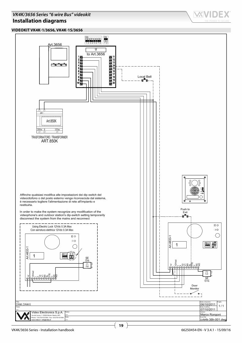
Installation diagramsVIDEOKIT VK4K-1/3656, VK4K-1S/3656
66250454-EN - V 3.4.1 - 15/09/1620
VK4K/3656 Series “6 wire Bus” videokit
VK4K/3656 Series - Installation handbook
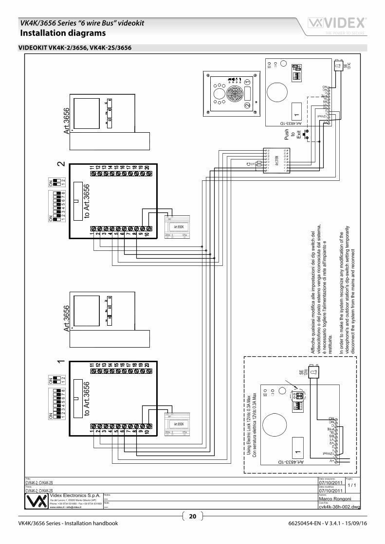
Installation diagramsVIDEOKIT VK4K-2/3656, VK4K-2S/3656
66250454-EN - V 3.4.1 - 15/09/1621
VK4K/3656 Series “6 wire Bus” videokit
VK4K/3656 Series - Installation handbook
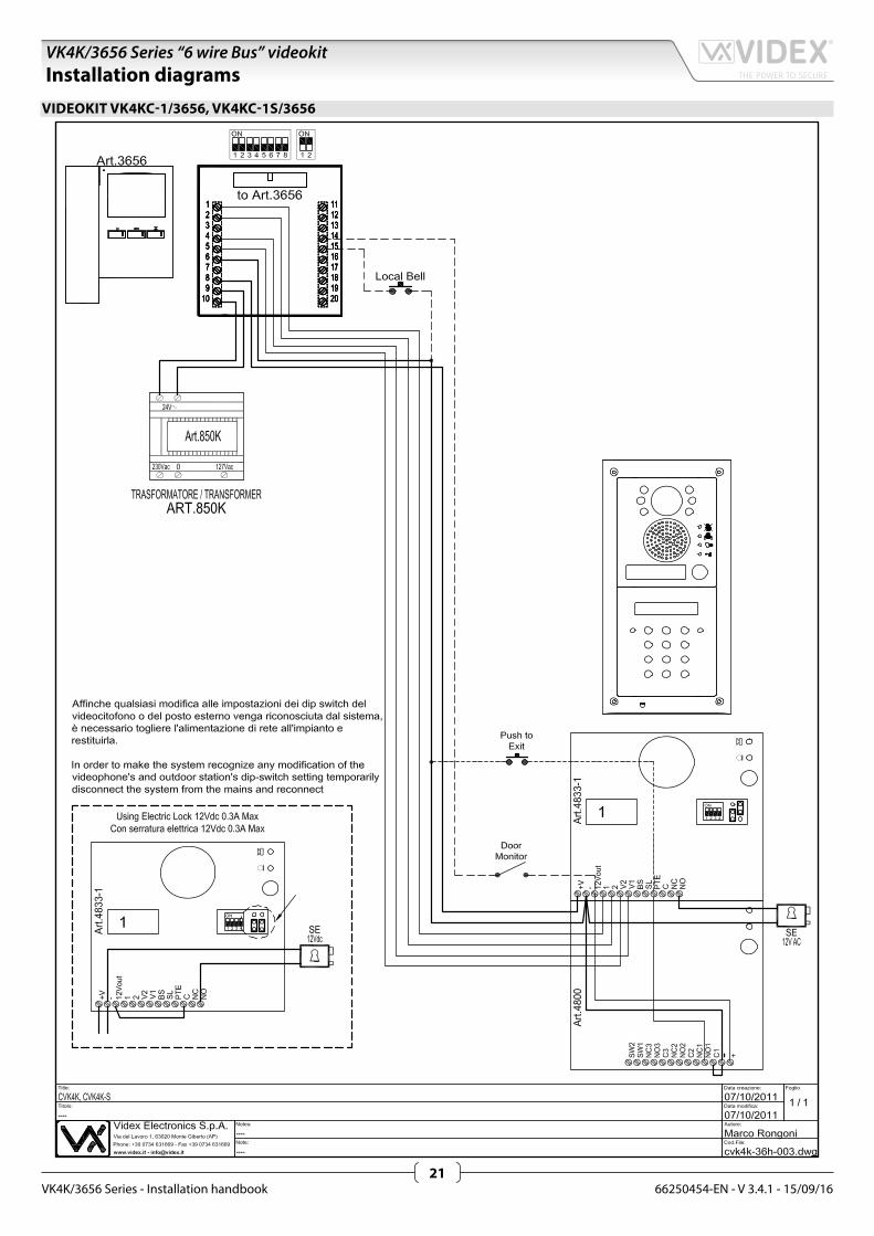
Installation diagramsVIDEOKIT VK4KC-1/3656, VK4KC-1S/3656
66250454-EN - V 3.4.1 - 15/09/1622
VK4K/3656 Series “6 wire Bus” videokit
VK4K/3656 Series - Installation handbook
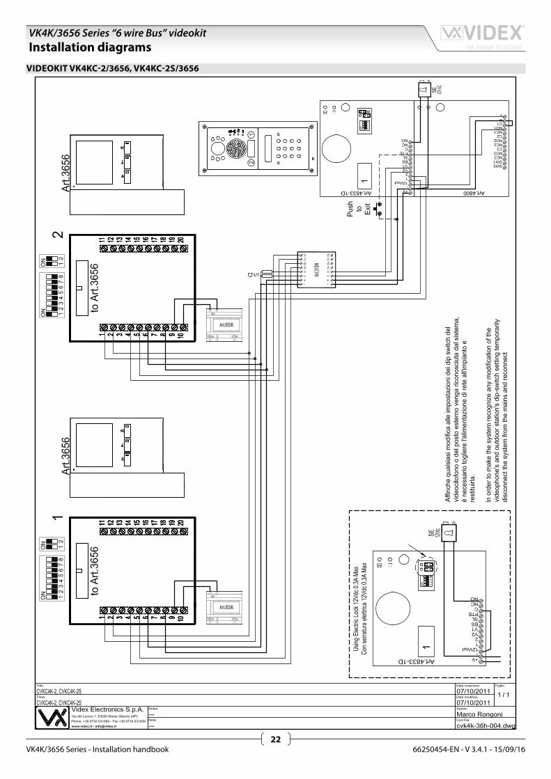
Installation diagramsVIDEOKIT VK4KC-2/3656, VK4KC-2S/3656

66250454-EN - V 3.4.1 - 15/09/1623
VK4K/3656 Series “6 wire Bus” videokit
VK4K/3656 Series - Installation handbook
Installation diagramsVIDEOKIT VK4K-1/3656, VK4K-1S/3656 WITH ADDITIONAL INTERCOM AND EXTENSION SOUNDER
66250454-EN - V 3.4.1 - 15/09/1624
VK4K/3656 Series “6 wire Bus” videokit
VK4K/3656 Series - Installation handbook
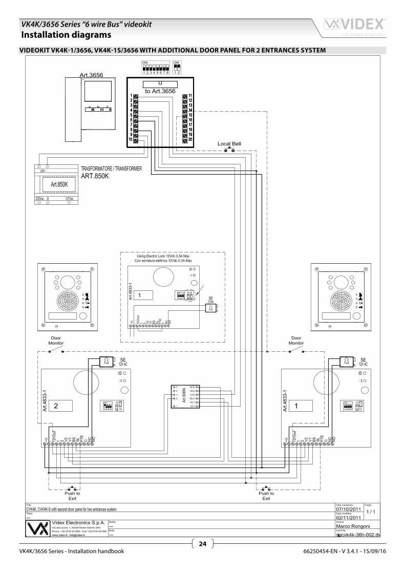
Installation diagramsVIDEOKIT VK4K-1/3656, VK4K-1S/3656 WITH ADDITIONAL DOOR PANEL FOR 2 ENTRANCES SYSTEM
66250454-EN - V 3.4.1 - 15/09/1625
VK4K/3656 Series “6 wire Bus” videokit
VK4K/3656 Series - Installation handbook
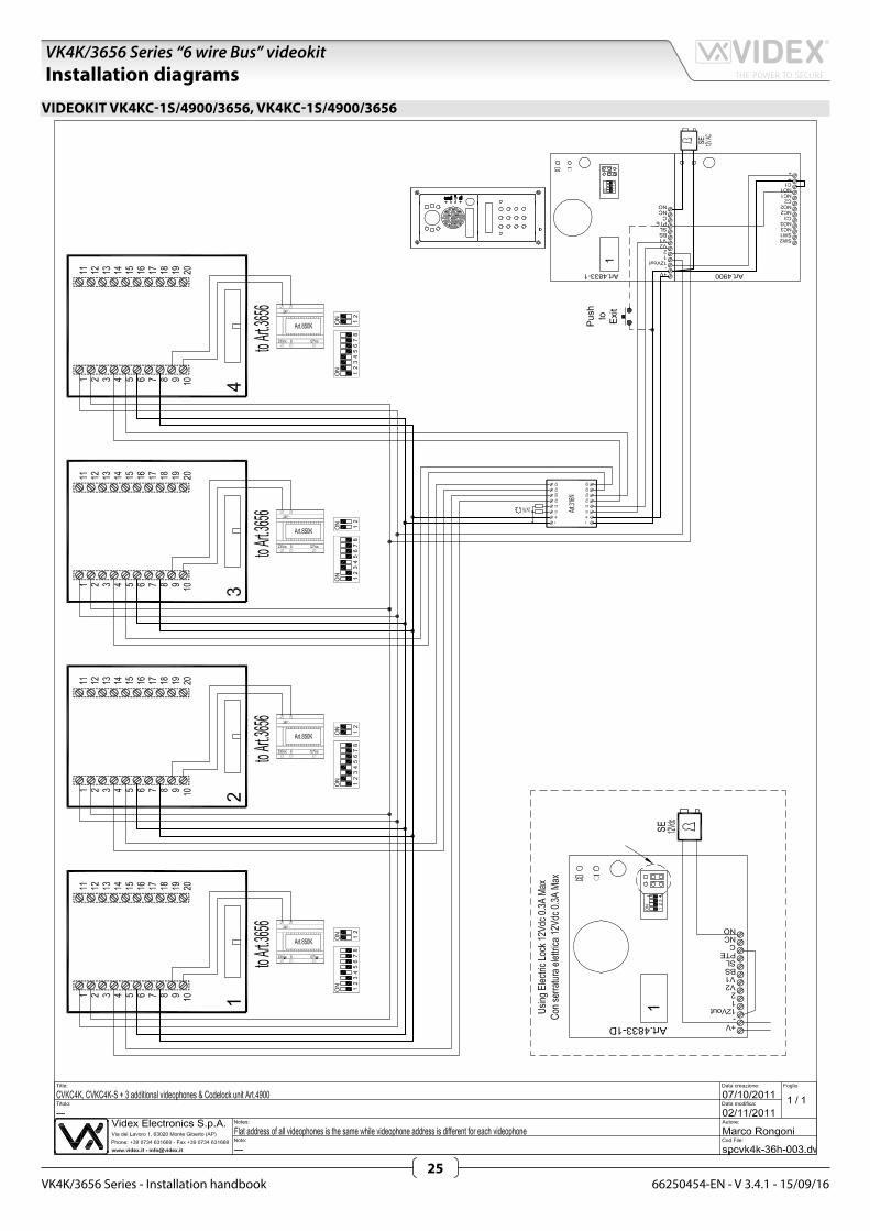
Installation diagramsVIDEOKIT VK4KC-1S/4900/3656, VK4KC-1S/4900/3656
66250454-EN - V 3.4.1 - 15/09/1626
VK4K/3656 Series “6 wire Bus” videokit
VK4K/3656 Series - Installation handbook
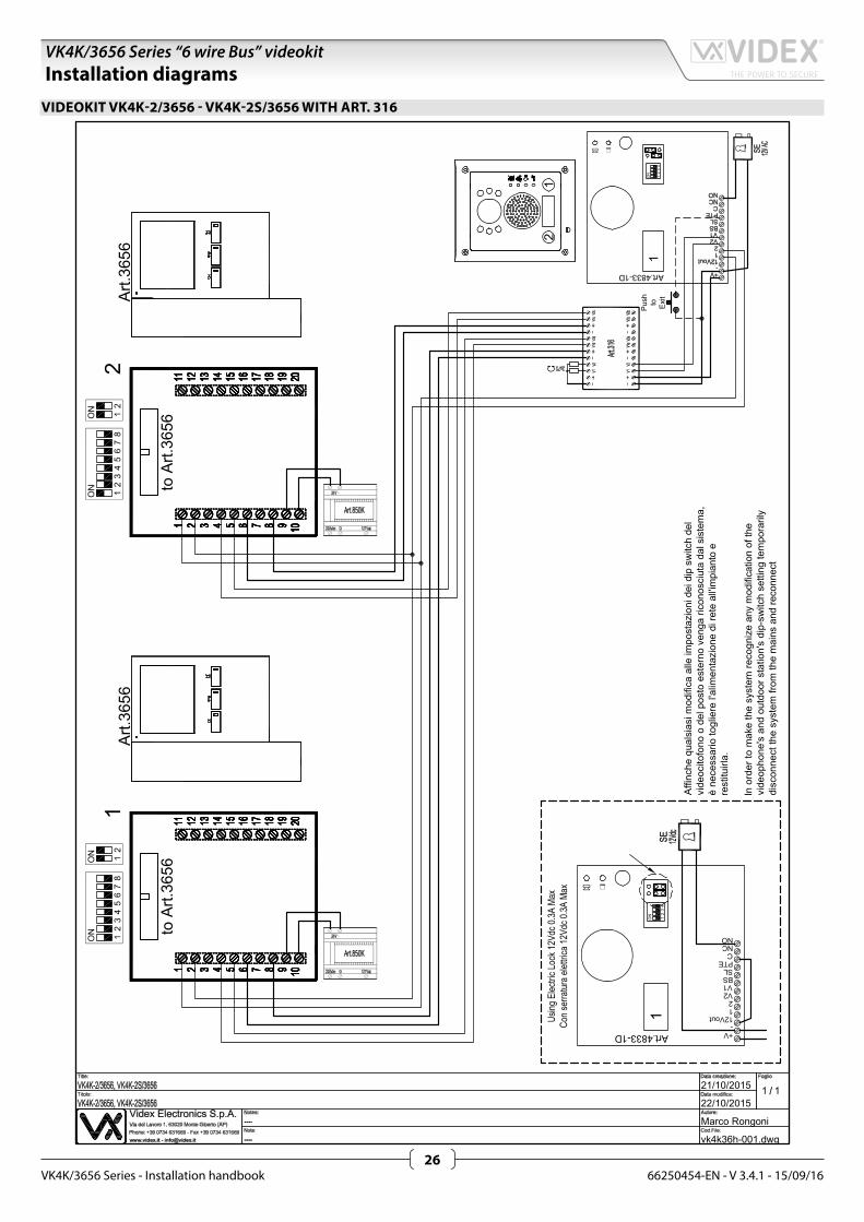
Installation diagramsVIDEOKIT VK4K-2/3656 - VK4K-2S/3656 WITH ART. 316
11
Marco Rongoni
vk4k36h-001.dwg
21/10/2015
22/10/2015
43
21ON
1
Art.4833-1D
Using
Elec
tric Lo
ck 12
Vdc 0
.3A M
axCo
n ser
ratur
a elet
trica 1
2Vdc
0.3A
Max
NC
V2
BS
PTESL
V1
2
-
112Vout
+V
C
NO
43
21O
N
1
Art.4833-1D
Pus
hto Exi
t
21
12
to A
rt.36
56
67
81
23
54
ON
12
ON
Art.
3656
to A
rt.36
56
67
81
23
54
ON
12
ON
Art.
3656
Affi
nche
qua
lsia
si m
odifi
ca a
lle im
post
azio
ni d
ei d
ip s
witc
h de
lvi
deoc
itofo
no o
del
pos
to e
ster
no v
enga
rico
nosc
iuta
dal
sis
tem
a,è
nece
ssar
io to
glie
re l'
alim
enta
zion
e di
rete
all'i
mpi
anto
ere
stitu
irla.
In o
rder
to m
ake
the
syst
em re
cogn
ize
any
mod
ifica
tion
of th
evi
deop
hone
's a
nd o
utdo
or s
tatio
n's
dip-
switc
h se
tting
tem
pora
rily
disc
onne
ct th
e sy
stem
from
the
mai
ns a
nd re
conn
ect
66250454-EN - V 3.4.1 - 15/09/1627
VK4K/3656 Series “6 wire Bus” videokit
VK4K/3656 Series - Installation handbook
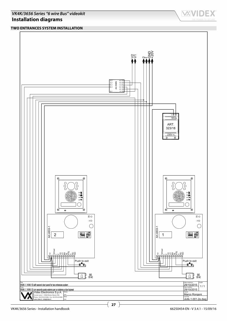
TWO ENTRANCES SYSTEM INSTALLATION
NC
V2 BS PTESLV12- 112V
out
+V C NO
4321
ON
2
Art.4
833-
1
NC
V2 BS PTESLV12- 112V
out
+V C NO
4321
ON
1
Art.4
833-
1
Art.
506N
1
4
2
3
5
NC1
C01
NC2
NO1
CO2
NO2
Push to exitPush to exit
+20V
GN
D12V1V2
18Vdc
230V
+ -
ART.323/18
Videx Electronics S.p.A.Via del Lavoro 1, 63846 Monte Giberto (FM)Phone: +39 0734 631669 - Fax +39 0734 631669www.videx.it - [email protected]
Autore:
Data modifica:
Data creazione:Title:
Notes:
Titolo:
Note: Cod.File:
Foglio
/ 11
Marco Rongoni
vk4k-1-001-2e.dwg
29/10/2015
29/10/2015
Installation diagrams

MANUFACTURERVIDEX ELECTRONICS S.P.A.Via del Lavoro, 1 - 63846 Monte Giberto (FM) ItalyTel (+39) 0734 631669 - Fax (+39) 0734 632475www.videx.it - [email protected]
CUSTOMER SUPPORTAll Countries:VIDEX ELECTRONICS S.P.A.www.videx.it - [email protected]: +39 0734-631669 - Fax: +39 0734-632475
UK Customers:VIDEX SECURITY LTDwww.videx-security.comTech Line: 0191 224 3174 - Fax: 0191 224 1559
The product is CE marked demonstrating its conformity and is for distribution within all member states of the EU with no restrictions. This product follows the provisions of the European Directives 2014/30/EU (EMC); 2014/35/EU (LVD); 2011/65/EU (RoHS): CE marking 93/68/EEC.
Main UK office:VIDEX SECURITY LTD1 Osprey Trinity ParkTrinity WayLONDON E4 8TDPhone: (+44) 0870 300 1240Fax: (+44) 020 8523 [email protected]
Northern UK office:VIDEX SECURITY LTDUnit 4-7Chillingham Industrial EstateChapman StreetNEWCASTLE UPON TYNE - NE6 2XXTech Line: (+44) 0191 224 3174Phone: (+44) 0870 300 1240Fax: (+44) 0191 224 1559
Greece office:VIDEX HELLAS Electronics48 Filolaou Str.11633 ATHENSPhone: (+30) 210 7521028 (+30) 210 7521998 Fax: (+30) 210 [email protected]
Danish office:VIDEX DANMARKHammershusgade 15DK-2100 COPENHAGENPhone: (+45) 39 29 80 00Fax: (+45) 39 27 77 [email protected]
Benelux office:NESTOR COMPANY NVE3 laan, 93B-9800 DeinzePhone: (+32) 9 380 40 20Fax: (+32) 9 380 40 [email protected]
Dutch office:NESTOR COMPANY BVBusiness Center Twente (BCT)Grotestraat, 64NL-7622 GM [email protected]