enhanced aluminum properties by means of precise droplet
TRANSCRIPT

Enhanced Aluminum Properties by Means of Precise Droplet Deposition
Melissa Orme and Robert F. Smith
Department of Mechanical and Aerospace Engineering University of California, Irvine CA 92697-3975
Accepted for Publication in
ASME Journal of Manufacturing Science and Engineering
Abstract
The use of molten aluminum droplets is investigated for potential application to Precision Droplet-Based
Net-Form Manufacturing (PDM). In the proposed application, final structural components are made
from the raw stock in one integrated operation by depositing molten metal droplets, layer after layer, via
computer information. This work investigates the feasibility of the proposed technology by investigating
the issues associated with generating molten aluminum droplets from capillary stream break-up, and
examining the mechanical characteristics of the fabricated aluminum components. New results are
presented which illustrate the generation of stable streams of molten aluminum droplets at rates of
24,000 droplets/second for a droplet stream speed of 10.9 m/s, corresponding to throughput rates of
2.3×10⁻⁴ kg/s (1.85 lb./hour). The droplets travel 2,500 droplet diameters in an inert environment
before impingement with the substrate. Microstructural images are completely devoid of splat
boundaries, which have been removed by remelting, and the grain size is approximately uniform
throughout the field of view of the image that, in most cases presented, contains easily upwards of 30
splats. Also, it has been found that the presence of aluminum oxide in the melt does not influence the

2
average grain size of the component. An oxide barrier however will encapsulate each grain if the oxides
are not removed by filtration in the pre-jetting stage. The presence of aluminum oxide in the melt does
not prohibit the removal of the splat boundaries. Mechanical analysis shows that fabrication with molten
aluminum droplet deposition results in a 30% increase in ultimate tensile strength compared to the raw
ingot stock.
1. INTRODUCTION
Rapid prototyping is now an established Time Compression Technology which leads to significant
competitive advantages in the manufacturing sector (Atkinson, 1997). Typical rapid prototyping
technologies such as Stereolithography (Jacobs, 1992) create prototypes necessarily made of
photopolymer resins or thermoplastic materials limiting the prototype to applications which do not
require the strength a fully functional part (e.g., used for applications of geometry and configuration
validation). Structural ceramic components are fabricated by the process of Fused Deposition Ceramics
(FDC) (Argarwala et al., 1995) which is based on the technology of Fused Deposition Modeling
(FDM) to make ceramic components from powder/binder filaments. Selective Laser Sintering (SLS) is
the Rapid Prototyping technology in which prototypes are constructed layer by layer from CAD
information where each layer of thermoplastic, metallic, or ceramic powder is locally heated with a laser
to fuse particles (Klock et al., 1995; Griffin et al., 1995; Pintat et al., 1995). Until recently, all SLS
green prototypes required post-treatment to reduce the large degree of porosity which would otherwise
severely limit their mechanical usefulness. SLS/HIP is a new process under development in which the
SLS processed part is post-processed by containerless Hot Isostatic Pressing to full density (Das et al.
1997).

3
Net-form manufacturing technologies are commonly viewed as a subset of Rapid Prototyping
technologies since the final component is manufactured directly from computer information in one
integrated operation. However, in net-form manufacturing, structural metallic components can be
made without any post-treatment.
This paper describes the generation and deposition of molten aluminum droplets from capillary stream
break-up for application to the emerging technology of Precision Droplet-Based Net-Form
Manufacturing (PDM) (Orme and Muntz, 1992; Orme, 1993), and examines the microstructure and
mechanical properties of the preliminary fabricated components. The technique of PDM could
theoretically employ any metal that can be contained in a crucible in its molten state. However, the work
presented in this paper, which examines the feasibility of the technology, is restricted to the generation
and deposition of pure molten aluminum droplets.
The technique of PDM, which is still under development, uses precisely controlled streams of molten
metal droplets as the deposition element that are characterized by speed dispersions ≤1×10⁻⁶ times the
average droplet speed and angular dispersions on the order of one micro-radian (Orme, 1991).
Droplets will be electrostaticly charged and deflected onto a substrate. The 3-D part is fabricated layer
by layer with conditions carefully controlled such that the thermal energy of the incoming droplets is
sufficient to locally remelt the previously delivered and solidified material (substrate), thereby maintaining
a high strength component by removing via phase change the boundaries between neighboring splats
(Orme et al., 1996, 1997; Amon et al. 1996, 1998). Microstructures of the fabricated components are
refined over their conventionally fabricated components (e.g., cast) due to rapid solidification of the

4
droplets. It is well known that rapid solidification leads to refined microstructures, which in turn leads to
enhanced mechanical properties.
Microstructural refinement from droplet deposition has been the subject of interest since at least the
early 1980’s. The literature is abundant with studies focused on the microstructural refinement of
components due to rapid solidification resulting from droplet deposition. A sample of these studies
include that due to Singer (1983), who evaluated a generation of new material characteristics including
refined microstructures with the technology of Spray Forming; Fielder et al. (1987), who examined the
microstructural refinement due to spray forming René 95 components; Lavernia et al. (1992), who
studied the microstructural refinement due to rapid solidification in aluminum alloys fabricated with
droplet spray deposition; Orme (1993), who studied the microstructural refinement of Rose’s metal
components that were fabricated with controlled droplet deposition; Orme et al., (1996), who studied
the microstructural characteristics of aluminum components fabricated with rapidly solidified molten
aluminum droplets; and Amon et al. (1996) who investigated the microstructural characteristics of
stainless steel and carbon steel droplets in their study that was primarily focused on substrate remelting.
Figure 1 is a conceptual schematic of the Precision Droplet-Based Net-Form Manufacturing (PDM)
technique. In this work, molten metal droplets are formed from capillary stream break-up at rates of
24,000 drops per second for a 50 micron radius orifice and for droplets travelling at 10.9 m/s
corresponding to a driving pressure of 20 PSI. Droplet deposition frequency is inversely proportional to
orifice radius so that droplets emanating from a 25 micron radius orifice would be generated at a rate of
48,000 droplets/second. The droplets are ejected into an inert environment and are targeted by means
of electrostatic deflection onto a substrate. Upon arrival at the substrate, they undergo a “splatting”

5
action that, under carefully controlled thermal conditions, entails simultaneous spreading, remelting of the
previously deposited and solidified material, followed by solidification. Movement of the x-y table in
accordance to CAD information coupled with electrostatic charging and deflection allows subsequent
droplet deliveries to build the 3-D part micro-layer by micro-layer without any mold. Since the droplets
rapidly solidify, detailed structures can be fabricated in the absence of macroscopic fluid flow.
PDM bears similarities with other emerging technologies of net-form manufacturing such as Shape
Deposition Manufacturing, SDM, (Prinz et al., 1995; Amon et al., 1996; Amon et al., 1998, Chin et al.,
1995) and 3-D printing (Sachs et al., 1992). In SDM, a feedstock wire located directly over the
substrate is melted using a plasma-welding torch. A discrete droplet of typical dimension 1-10 mm
(depending on plasma conditions) falls off the wire and onto the substrate thereby building the material
component. In 3-D Printing, a green part is created by printing a stream of binder droplets onto a metal
powder bed according to CAD information. However in that process, several post-treatment steps are
necessary to insure a mechanically sound component.
The aim of this paper is not to demonstrate PDM, which is still an immature technology. Rather, this
paper is focused on substantiating the feasibility of the technology by providing new engineering details
of molten aluminum droplet formation and the requisite apparatus, as well as microstructural and
metallurgical analysis of preliminary structures fabricated with the technology.
2. BACKGROUND
The crux of the PDM technique lies in the ability to generate continuous streams of precisely controlled
droplets. Previous research has illustrated the intrinsic lateral stability on the order of a micro-radian for

6
droplet streams composed of oil or molten solder (Orme and Muntz, 1990). It has been shown that the
vertical stability, which is characterized by the speed dispersions of the droplets, can be controlled to a
high degree of accuracy (e.g., ≤ 1 part in 106) when imposing carefully controlled frequency
perturbations on the stream which initiates droplet formation (Orme, 1991). In order to achieve
accurate electrostatic charging and subsequent deflection, the charging waveform must be perfectly
synchronized with the frequency disturbance that drives droplet formation. A droplet stream
characterized by large speed dispersions would result in gross targeting errors since speed dispersions
directly translate to errors in droplet charge acquired. Hence, the droplet generator must be one that
does not introduce additional unwanted harmonics on the capillary stream that would otherwise cause
velocity dispersions or jitter.
Figure 2 illustrates the general phenomenon of droplet generation from capillary stream break-up. An
axisymmetric jet of radius ro issues from an orifice as shown. A periodic disturbance of wavelength λ
resulting from motion of a vibrating rod initiates a radial disturbance on the circumference of the jet. The
motion of the rod is due to that of a piezoelectric crystal that is bonded to the upper end of the rod. If
the disturbance is chosen such that ko*<1.0, where ko
*=2πro/λ, then the disturbance will grow until
droplets of radius rd are pinched from the stream. The droplet radius is related to the undisturbed stream
radius, ro, by conservation of mass:
31
20
31
*0 4
323
=
=
fVr
krr od
π
7
In the above, V is the stream speed and f is the disturbance frequency. Previous work (Orme, 1991)
has shown that a droplet stream is most uniform (i.e., is characterized by the most uniformly separated
and sized droplets) when the capillary stream is perturbed with the ko* which corresponds to the
maximum disturbance growth rate, β, on the capillary stream. For fluids that are nearly inviscid such as
water and most molten metals, this ko*=0.697. Hence, for the conditions employed in this work (initial
stream radius, or , of 50 µm, and a stream speed, V, of 10.9 m/s), the driving frequency used is that
which generates a highly uniform droplet stream which is given by the relation
)2/()( *oo rVkf π= =24,000 Hz, where ko
*=0.692 is used.
The droplets are charged by surrounding the capillary stream with a charge electrode at the location that
includes the droplet formation point. By carefully synchronizing the periodic disturbance initiating
droplet formation with the charging waveform, drops can be charged on a drop-to-drop basis. This
paper is focused on details of molten aluminum droplet formation, and not on droplet charging and
deflection. Previous studies have detailed results from droplet charging and deflection of molten metal
(Orme et al., 1996).
3. EXPERIMENTAL APPARATUS
Previous work has illustrated the stable generation of oil or molten solder droplets from capillary stream
break-up (Orme, 1993; Orme and Muntz, 1990; Orme, 1991; Orme et al., 1996). Although it is a
straightforward extension in droplet formation theory, the generation of molten aluminum droplets from a
100 µm diameter orifice is not a straightforward extension in technology due to its higher melting point
and its corrosive nature in the molten state. These two issues are addressed in the design and

8
fabrication of a state-of-the-art apparatus for molten aluminum droplet generation that is described in
this section.
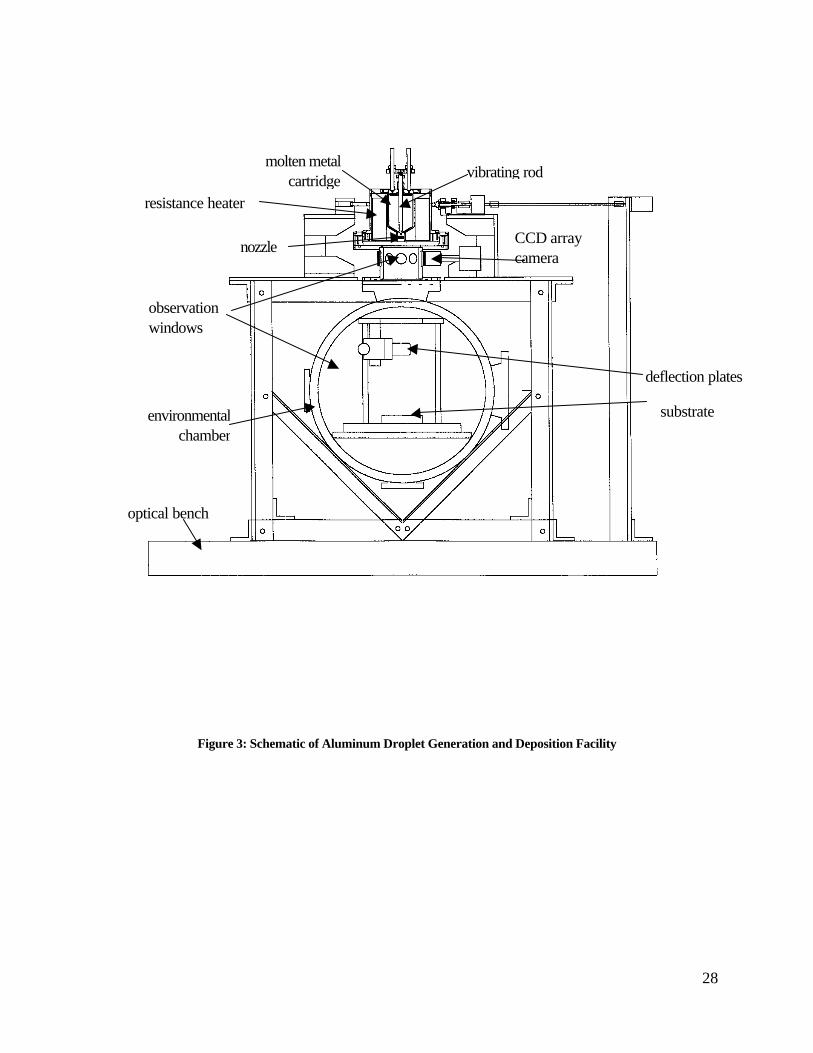
Figure 3 is a schematic of the existing facility. The main component is an environmental chamber that
sits upon a vibrationally isolated optical bench. An observation cylinder equipped with eight optical
quality glass windows couples the environmental chamber to the droplet generator. Two CCD array
cameras and two light sources aid in monitoring the droplet stream’s position as it flies through the
observation cylinder. The droplet generator is housed in a socket assembly that allows angular
positioning of the droplet stream. The distance between the exit face of the orifice and the copper
substrate is 50 cm. In operation, ambient air is evacuated from each component of the facility, as
oxygen has been found to have a detrimental effect on both droplet formation and the integrity of the
resulting deposit, and an inert gas such as argon or nitrogen is bled into the system. The purity of the
bottled gas is specified at 99.998%, and the oxygen level of gas in the environmental chamber is
monitored to insure that the O2 level does not exceed 25 PPM. A background pressure of 14.7 psi is
used in this work.
Aluminum is severely corrosive in the molten state, and was found to dissolve high grade stainless steel,
steel alloys such as Inconel, and some refractory materials such as molybdenum. It was found that
titanium corroded the least when in contact with the melt. Hence, the main component of the droplet
generator, which consists of a cylindrical cartridge fitted with an orifice on the lower end and a cap on
the upper end, was machined from titanium and coated with boron nitride. Figure 4 illustrates a
conceptual schematic of the titanium cartridge, resistance heater, and plunger rod. Not shown is the
restraining hardware of the piezoelectric crystal. While ceramics such as alumina would also be resistant

9
to corrosion and suitable for use in certain design configurations, the hardware design employed in this
work requires a material to be used which can bear a load in compression, deeming titanium a more
suitable choice.
The vibration that initiates the stream’s radial instability and subsequently produces droplets is
introduced with motion from a piezoelectric crystal (PZT5-H). When jetting low temperature fluids
such as oil, water, or molten solder, the PZT can be immersed directly in the fluid thereby reducing
structural vibrations. However the PZT must be shielded from extreme temperatures such as those
associated with the jetting of molten aluminum. We have therefore designed a vibrating rod system that
is machined from titanium and coated with boron nitride that restricts the transfer of thermal energy to
the PZT (by employing water cooling lines near the PZT) but provides the necessary pressure
fluctuation to the molten metal directly above the orifice. Care has been taken to decouple the motion
of the PZT from the rest of the apparatus thereby reducing the application of unwanted disturbances
such as apparatus resonances.
Natural diamond was chosen as the orifice material since it was assumed to be most resilient to
corrosion. Usage of the diamond orifice results in a stable and uniform droplet stream. However,
examination of the orifice with the use of a Scanning Electron Microscope illustrates that the diamond
was eroded by the molten aluminum. Further energy dispersed X-ray analysis (EDXA) of the diamond
orifice indicated peaks at carbon, aluminum, and oxygen. It is emphasized that the aluminum eroded
away the diamond as aluminum was found within the diamond and not on the outer surface. No traces
of AlC were found. Figure 5a is a SEM photograph illustrating the surface of the diamond orifice that
had been jetted for a two-hour period. The originally smooth circular entrance had become notched at
10
several locations. A different view with increased magnification is illustrated in figure 5b. The region on
the right half of the figure has been exposed to molten aluminum for a two-hour period, while the region
to the left has been exposed for only one hour with the use of a gasket. Clearly, the region that was
exposed for two hours has been significantly eroded on the surface. This is an interesting finding in its
own right since the diamond is contained in an inert environment and maintained at temperatures much
less than that which is known to cause diamond erosion.
4. RESULTS
Droplet streams were generated with pure aluminum, which has a melting temperature of 933K, a liquid
density of 2380 kg/m3, a solid density of 2707 kg/m3, and a latent heat of 402 J/kg. The jetting
temperature is held at 30C above its melting temperature, and the background environment gas is argon
held at a constant 14.7 psi.
4.1 Droplet Generation
In order to achieve a stable droplet stream (characterized by minimal angular and speed dispersions), it
was found necessary to filter the molten aluminum. While it is true that molten aluminum is a highly
corrosive fluid, and therefore dissolves many of its own contaminants thereby acting as a self-filtering
fluid, it was found that aluminum oxides were immune to its self-filtering nature. Hence, even though the
raw stock was advertised to be of highly pure quality (99.99% from Accumet Materials Co of Ossining,
NY), it was found that there was inevitably a significant amount of aluminum oxides in the melt which

11
have proven to have a deleterious effect on stream stability. Our approach was to filter the melt with
custom fabricated graphite filter plates.
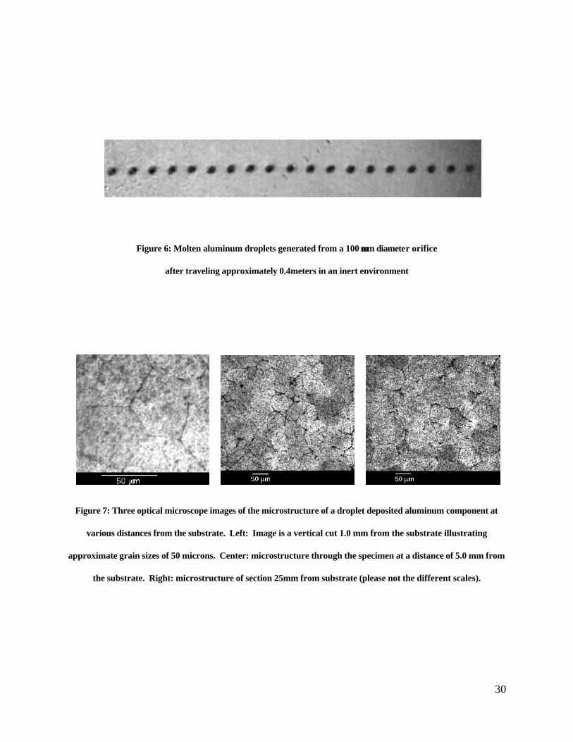
Figure 6 illustrates a molten aluminum droplet stream after having traveled a distance of approximately
0.4 meters in an inert environment, which corresponds to approximately 2,500 droplet diameters. The
droplets were driven with a stagnation pressure of 20-psi (137.8 kPa) above ambient which
corresponds to a stream speed of 10.9 m/s. It is the author’s understanding that this is the first report of
the generation of molten aluminum droplet streams from capillary stream break-up and the subsequent
stable propagation to significant distances in an inert environment. Hence, with proper care to insure
that the obstacles of oxidation and materials corrosion are overcome, molten aluminum droplet
generation from capillary stream break-up is achievable and therefore appears to be feasible for the
emerging PDM technology.
4.2 Droplet Deposition
Droplet deposits were made by allowing the droplets to impinge upon a substrate where they solidify.
In this phase of PDM development, droplet charging is not employed so that consecutive droplet
depositions to one location on the substrate build a solid circular cylinder. Cylinders as high as 0.15
meters have been deposited and analyzed as discussed below. Since the droplets are deposited onto
the same location of the substrate every 42 microseconds (1/24,000 Hz), the previously deposited
material has had insufficient time to cool to the original substrate temperature (initially 293K), causing
the temperature of the deposit to increase with time (i.e., with successive splat depositions). This
warming trend of the previously deposited and solidified material causes the solidification time to

12
increase, which has two effects. First, the grain size is expected to be larger than that which would
occur in a rapid solidification process (e.g., the final realization of the PDM process that includes droplet
charging and deflection), and hence the metallurgical properties that vary with grain size will be of a
lower quality. Second, during the initial droplet depositions, the diameter of the circular cylinder
increases as the number of splats increases to a size which is larger than a single splat diameter. Hence,
the diameters of the circular cylinders deposited were found typically to increase from a few millimeters
at the lower end (i.e., at the interface of the first splat with the initial substrate) to approximately 1.0 cm
at a distance from the initial substrate which varies with jetting conditions (such as deposition frequency
and impact temperature), but is typically on the order of 1.0 cm. At heights above 1.0 cm the diameter
is relatively constant. The reason why the cylinder diameter becomes wider than the splat diameter is
due to the fact that as the droplets are deposited onto the same location at high deposition rates, the top
surface of the cylinder has insufficient time to cool before the next droplet is delivered. Hence, the
temperature of the top surface of the cylinder increases with distance away from the substrate (or
number of splat delivered), causing the remelt zone to increase with increasing distance from the
substrate. The relatively thick molten cylinder tip causes the fluid to flow prior to solidification, which in
turn causes cylinder widening. The issue of cylinder widening has no practical consequence for the
development of the PDM technology since in the final realization, the droplets would be electrostaticly
deflected onto the substrate in order to create complicated 3-D geometries, thereby permitting the
droplets to rapidly solidify prior to the arrival of a new splat.
4.3 Deposit Characterization
13
Microstructures
Micrographs of sections of the deposited cylinders are shown in Figures 7-9. Figure 7 is included to
illustrate the variation in grain size at different locations in the cylinder, and figures 8 and 9 are included
to illustrate the effect of melt filtration. All micrographs are taken from vertical sections of various
deposited cylinders so that they are cut through many splat layers. The samples in Figure 7 were etched
at UCI with a modified version of Keller’s Reagent, which consists of 31% H20, 31% HCl, 31% HNO3
and 7% HF. Before applying the etchant, the surfaces were manually polished to a reflecting shine. The
samples were initially polished with a synthetic sapphire polish that had a grain size of 1 µm, and
subsequently polished with Buehler micropolish compound of 0.5 and 0.3µm grain respectively.
Figure 7 illustrates the microstructure of the same component at three locations from the substrate. The
component was fabricated with coarsely filtered molten aluminum. The left image illustrates the
microstructure 1.0 mm from the substrate surface. It can be seen that the grains are on the order of 50
µm. The center photograph is a section of the microstructure at a distance 5.0mm from the substrate,
and the photograph on the right illustrates the microstructure at a distance of 25mm from the substrate.
In these optical photographs, as well as in all observations, no splat boundaries were found at any
location. The retention of individual splat boundaries would lead to a component with poor mechanical
qualities. In the photographs illustrated in Figure 7, the average grain size appears to be on the order of
50 µm for the samples evaluated at 1.0 and 5.0 mm from the substrate. It is seen that the grain size is
somewhat larger at a distance of 25.0 mm from the substrate, though not appreciably. It is worth noting
that the grain size of the cast ingot was on the order of millimeters.
14
The micrographs in Figure 8 provide a dramatic presentation of the effect of filtering the jetting melt.
Both images are at the same magnification, and the total field of view is 160x190µm. The image on the
left is taken from a vertical section of a cylinder that was fabricated with unfiltered molten aluminum, and
that on the right corresponds to a deposited cylinder that was fabricated with filtered molten aluminum.
The structure that was fabricated with unfiltered molten aluminum has identifiable pores and oxide grain
boundary encapsulation. The microstructure of the component that was fabricated with filtered molten
metal is free of visible oxide grain boundaries and pores. The observable speckle on both figures
(which is more prominent in the figure on the right) is believed to be an artifact of etching and are not
pores (as attested by density measurements discussed later).
The images in Figure 9 illustrate expanded views of the images in Figure 8, each with a total view of
800x970µm. Again, individual splat boundaries are not present, and the grain size is approximately
uniform throughout the entire field of view. Pores and oxide grain boundaries are visible in the image
that was fabricated with unfiltered molten aluminum, and are invisible in the image corresponding to the
component fabricated with filtered molten aluminum.
Mechanical Characteristics
Three test coupons were machined from three separate droplet deposited circular cylinders fabricated
with filtered molten aluminum (specimen 1, 2, and 3). An additional coupon was machined from a
circular cylinder that was fabricated with unfiltered molten aluminum (specimen 4). The asterisk (*)
indicates that the measurement was made six months after fabrication. Specimens 1 and 2 were sent to
the Boeing Commercial Airplane Group for evaluation, and specimens 3 and 4 evaluated by Anaheim
15
Test Laboratory. Table 1 below provides a summary of the results of the three specimens in addition to
the results from the raw ingot that was used as the jetting material for comparison purposes.
The average ultimate tensile strength of the droplet-deposited specimens 1, 2 and 3 (all filtered) is 8,900
where the corresponding measured value for the raw stock is 6,816 PSI. Hence, even in the current
immature stage of the PDM technology, a gain of 30% in ultimate strength is achieved. Measurements
of the 0.2% offset yield strength for the same three specimens showed a modest increase over the raw
stock with values of 4,500, 4,900, and 6,415 PSI, compared to a value of 4,010 PSI for the raw
stock. No appreciable change in elongation was observed in the specimens fabricated with filtered
aluminum (specimens 1, 2 and 3), and the raw stock as the average elongation for specimens 1, 2 and 3
is 38.3%, and that for the raw stock is 37%. The density of the droplet deposited specimens (fabricated
from filtered melt, i.e., specimens 1, 2, and 3) and the raw stock had no measurable difference,
indicating very low porosity as attested visually by the photographs in Figures 7, 8, and 9 of the
specimens fabricated with filtered molten aluminum.
Additionally, a sample that was fabricated with unfiltered molten aluminum was evaluated. This sample
was fabricated early in this research endeavor before the importance of filtering with respect to stream
stability was recognized. Using unfiltered molten metal results in orifice plugging in approximately 80%
of the experimental attempts. Then, when a stream is ultimately established, its trajectory is often erratic
with time due to the passage of micro-contamination (which is believed to be aluminum oxide) through
the orifice, thereby reducing the probability of fabricating a constant diameter cylinder suitable for tensile
strength evaluation. Hence, investigation of the effects of filtration on mechanical properties is not a
straightforward task. We have, however, fabricated one sample that was made with unfiltered molten

16
aluminum from which a test coupon was machined for tensile strength evaluation. This sample is listed
as specimen 4 in the table below. The asterisk indicates that the mechanical testing was performed 6
months after the sample was fabricated, whereas the other specimens without asterisks were analyzed
within one week of fabrication, hence a comparison may not be entirely valid since the mechanical
properties may have varied over time. With this in mind, it can be seen that the ultimate tensile strength is
9,461 PSI, the 2% offset yield strength is a comparatively high value of 8,734 PSI, the elongation and
density are measured to be 41% and 2,670 kg/m3 respectively indicating the presence porosity as
attested visually by the photographs in Figures 8 and 9. In order to ascertain if the unexpected increase
in strength for the unfiltered specimen is due to age hardening, we reevaluated one of the filtered
specimens (specimen 2) for strength after a six month waiting period. The results of this test are
included in the table with as entry 2*. It can be seen that there is a modest increase in tensile strength,
and significant increases in 2% offset yield strength and elongation. The density is unchanged as
expected. Hence, one can only conclude that the values of the aforementioned properties tend to
increase with time, and therefore, the cause of the increase in the said mechanical properties in the
sample fabricated with unfiltered metal is due to age hardening rather than the fact that it was made with
unfiltered molten aluminum. A direct comparison between un-aged filtered and unfiltered components is
not possible due to the difficulty in acquiring unfiltered cylinders as discussed above.
Sample Ultimate Tensile Strength
0.2% Offset Yield Strength
Elongation Density
1: filtered 8,800 PSI 4,900 PSI 48% Not available
2: filtered 9,000 PSI 4,500 PSI 34% not available
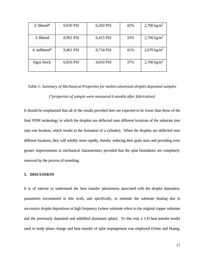
17
2: filtered* 9,030 PSI 6,260 PSI 42% 2,700 kg/m3
3: filtered 8,901 PSI 6,415 PSI 33% 2,700 kg/m3
4: unfiltered* 9,461 PSI 8,734 PSI 41% 2,670 kg/m3
Ingot Stock 6,816 PSI 4,010 PSI 37% 2,700 kg/m3
Table 1: Summary of Mechanical Properties for molten aluminum droplet deposited samples
(*properties of sample were measured 6 months after fabrication)
It should be emphasized that all of the results provided here are expected to be lower than those of the
final PDM technology in which the droplets are deflected onto different locations of the substrate (not
onto one location, which results in the formation of a cylinder). When the droplets are deflected onto
different locations, they will solidify more rapidly, thereby reducing their grain sizes and providing even
greater improvements in mechanical characteristics provided that the splat boundaries are completely
removed by the process of remelting.
5. DISCUSSION
It is of interest to understand the heat transfer phenomena associated with the droplet deposition
parameters encountered in this work, and specifically, to estimate the substrate heating due to
successive droplet depositions at high frequency (where substrate refers to the original copper substrate
and the previously deposited and solidified aluminum splats). To this end, a 1-D heat transfer model
used to study phase change and heat transfer of splat impingement was employed (Orme and Huang,
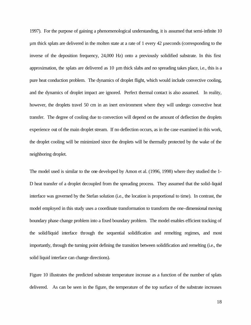
18
1997). For the purpose of gaining a phenomenological understanding, it is assumed that semi-infinite 10
µm thick splats are delivered in the molten state at a rate of 1 every 42 µseconds (corresponding to the
inverse of the deposition frequency, 24,000 Hz) onto a previously solidified substrate. In this first
approximation, the splats are delivered as 10 µm thick slabs and no spreading takes place, i.e., this is a
pure heat conduction problem. The dynamics of droplet flight, which would include convective cooling,
and the dynamics of droplet impact are ignored. Perfect thermal contact is also assumed. In reality,
however, the droplets travel 50 cm in an inert environment where they will undergo convective heat
transfer. The degree of cooling due to convection will depend on the amount of deflection the droplets
experience out of the main droplet stream. If no deflection occurs, as in the case examined in this work,
the droplet cooling will be minimized since the droplets will be thermally protected by the wake of the
neighboring droplet.
The model used is similar to the one developed by Amon et al. (1996, 1998) where they studied the 1-
D heat transfer of a droplet decoupled from the spreading process. They assumed that the solid-liquid
interface was governed by the Stefan solution (i.e., the location is proportional to time). In contrast, the
model employed in this study uses a coordinate transformation to transform the one-dimensional moving
boundary phase change problem into a fixed boundary problem. The model enables efficient tracking of
the solid/liquid interface through the sequential solidification and remelting regimes, and most
importantly, through the turning point defining the transition between solidification and remelting (i.e., the
solid liquid interface can change directions).
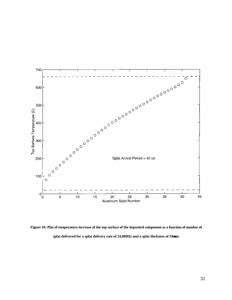
Figure 10 illustrates the predicted substrate temperature increase as a function of the number of splats
delivered. As can be seen in the figure, the temperature of the top surface of the substrate increases

19
with the number of splat delivered due to the rapid rate of droplet deposition which provides insufficient
time for complete splat cooling to occur between successive droplet deliveries.
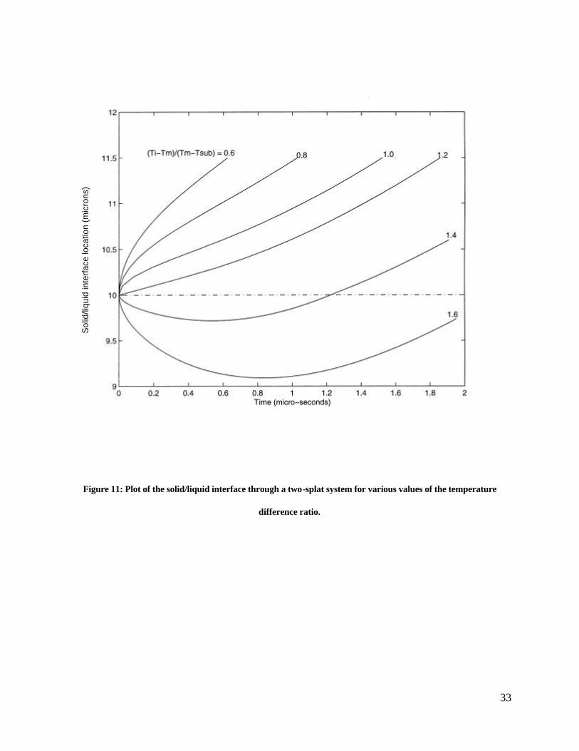
Figure 11 illustrates the numerically determined criterion used to estimate the substrate temperature,
Tsub, and the incoming droplet temperature, Ti, required to initiate the remelting of the previously
deposited and solidified splats for the purpose of removing splat boundaries. Shown is the solid/liquid
interface through a two-splat system, where each splat is 10 µm thick. It can be seen from the figure
that the solid liquid interface penetrates down into the previously solidified material for temperature
difference ratios, (Ti-Tm)/(Tm-Tsub), equal or greater than 1.4, where Tm is the melting temperature, Tsub
is the substrate temperature, and Ti is the incoming droplet temperature. For increasing values of the
ratio of temperature differences, the remelt depth through the previously deposited and solidified splat
increases. Values of the ratio much less than 1.4 prohibits the downward motion of the solid/liquid
interface. In these cases, the material impinges on the previously delivered and solidified splat and
solidifies without remelting the previous splat. Hence the slope of the solid liquid interface is always
positive for these cases. The model provides a first estimate of the substrate temperature necessary to
initiate the onset of remelting and the remelt depth. As the temperature ratio increases (e.g., as the
substrate temperature increases), the depth of the remelt zone increases as can seen in Figure 11 by the
downward extent of the solid-liquid interface into the previously deposited material.
For the conditions employed in this work, in which the incoming droplet temperature is held constant at
30C above the melting point, it is estimated that a substrate temperature of 911K is required to achieve
substrate remelting. Examination of Figure 10 indicates that this temperature is achieved after a
deposition of approximately 40 splats, which corresponds to a vertical distance of approximately 400

20
µm from the initial substrate surface (within the approximations of this model). Hence, at deposit heights
greater than 400 µm, it is expected that substrate remelting will occur and therefore all splat boundaries
at will be obliterated by the mode of phase change. This is attested by our experimental observations
shown in figures 7 (frames center and right), and figures 8 and 9, the later two were taken at distances
greater than 1.0cm from the substrate. The splats in the component at vertical positions less than 400
µm can also be removed by remelting due to increased remelt depths caused by increased substrate
heating resulting from droplets delivered at higher distances. Hence the criterion for the onset of
remelting is estimated to be when the temperature ratio (Ti-Tm)/(Tm-Tsub) = 1.4, and the remelt depth is
minimal. However for higher substrate temperatures, the temperature ratio will have higher values
thereby causing the solid-liquid interface to penetrate deeper into the previously solidified material,
remelting larger vertical zones of material. This phenomenon is observed in experiment, where thick red
zones (on the order of 10.0 mm) can be seen visually during the droplet deposition process. Hence it is
felt that the splat boundary removal at the 1.0mm distance is due to the deposition of droplets far from
the 1.0mm distance which, at the time of their delivery, have caused considerable substrate heating
which subsequently causes the solid-liquid interface to penetrate deep into the previously solidified
material removing the splat boundaries.
In order to facilitate splat boundary remelting throughout the entire component, either the substrate
could be heated, or the incoming droplet temperature can be increased to compensate for a cooler
substrate as illustrated in Figure 11. Either solution will necessarily be employed in the final realization of
the PDM technology.

21
6. SUMMARY
This work describes the early phase of development of the PDM net-form manufacturing technology.
Though the technology is still immature, several new and significant findings have been presented in this
work and are summarized here.
It has been shown that streams of stable, uniformly sized molten aluminum droplets can be formed from
capillary stream break-up and travel distances up to 2,500 droplet diameters in an inert environment.
The main issues that have been found to have a profound affect on stream stability are aluminum oxides
in the pre-jetted melt, and corrosion of the nozzle due to the solvent nature of the molten aluminum. The
latter issue is a problem not only due to degradation of the nozzle, but also because of the introduction
of contaminants into the pre-jetted melt.
It was found that molten aluminum corroded a natural diamond orifice, even though it was in an inert
environment and held at a temperature lower that that known to cause diamond corrosion. No
formation of AlC was found from the analysis of the nozzle. It is believed that this is the first time such
an aluminum/diamond reaction has been reported.
Circular cylinders (towers) were fabricated up to 0.15m high by depositing the molten aluminum
droplets onto the same location on the substrate. Microstructures of vertical sections revealed no splat
boundaries in the component, and approximately uniform microstructures throughout the field of view of
the images. A small increase in grain size was observed in a sample that was 25mm from the substrate
compared to samples at 1.0 mm and 5.0 mm from the substrate.
The presence of oxide grain boundaries and pores in cylinders fabricated with unfiltered molten
aluminum was reported. Cylinders fabricated with filtered molten aluminum were devoid of visible

22
oxide grain boundaries and voids. The grain size of the components fabricated with unfiltered and
filtered molten aluminum was approximately equal.
Mechanical testing revealed that the droplet deposited components had a 30% increase in ultimate
tensile strength (filtered or unfiltered). The components made from filtered molten aluminum showed no
decrease in density over the raw stock, indicating minimal, if any, porosity. The samples fabricated with
unfiltered molten aluminum showed a 1.1% decrease in density.
Hence, this work illustrates that fabrication of components from molten aluminum droplet deposition
leads to significant microstructural refinement and mechanical property enhancements when care has
been taken to filter the molten metal prior to jetting. It is believed that the results presented here are an
underestimate of the microstructural refinement and mechanical quality enhancements of the final PDM
technology. This is because the droplets did not solidify as rapidly as they will in the final PDM
technology since electrostatic charging and deflection was not employed. In the final realization of
PDM, the droplets will be deflected to different locations on the substrate, allowing the splats to cool
prior to the next splats arrival. In this manner, the temperature of the previously deposited and solidified
material will not increase with time, allowing the droplets to rapidly solidify which leads to refined
microstructures and enhanced mechanical properties.
ACKNOWLEDGMENTS
This work was made possible with the generous grants from Boeing Commercial Airplane Group
(BCA-23483), Lawrence Livermore National Laboratories (B345710), and the National Science

23
Foundation (DMI-9457205, DMI-9622400). Additional thanks is extended to the Boeing Commercial
Airplane Group for taking the micrographs shown in Figures 8 and 9, to Mr. Charles Huang for
preparing the sample shown in Figure 7, and to Mr. Changzheng Huang for providing the simulations
shown in Figures 10 and 11.
24
REFERENCES
Atkinson, D. 1997, Rapid Prototyping and Tooling, A practical Guide, Strategy Publications, Weltech
Centre, Ridgeway, Welwyn Garden City, Herts AAL72AA, UK
Amon, C.H., Schmaltz, K.S., Merz, R., Prinz, F.B., 1996 “Numerical and Experimental Investigation
of Interface Bonding Via Substrate Remelting of an Impinging Molten Metal Droplet” ASME J. of Heat
Transfer, 118, 164-172
Amon, C.H., Beuth, J.L., Merz, R., Prinz, F.B., and Weiss. L.E., 1998, “Shape Deposition
Manufacturing with Microcasting: Processing, Thermal and Mechanical Issues, ASME J. Manufacturing
Science and Engineering, Vol. 120, pp 656-667
Argarwala M.K., Van Werren R, Jamalabad V., Langrana N., Whalen P., Danforth S.C., and Ballard
C. 1995, “Quality of Parts Processed by Fused Deposition” Proceedings to the Solid Freeform
Fabrication Symposium, University of Texas at Austin
Chin, R.K., Beuth, J.L., and Amon, C.H., 1996 “Thermomechanical Modeling of Molten Metal
Droplet Solidification Applied to Layered Manufacturing,” Mechanics of Materials, Vol. 24, pp 257-
271
Das, S., Wohlert, M., Beaman, J., Bourell, D., 1997 “Direct Selective Laser Sintering and
Containerless Hot Isostatic Pressing for High Performance Metal Components” Proceedings to the
Solid Freeform Fabrication Symposium, University of Texas at Austin

25
Fielder, H.C., Sawyer, T.F., Kopp, R.W., and Leatham, A.G. (1987), “The Spray Forming of
Superalloys,” Journal of Metals, 28-33
Griffin E.A., McMillan S., Griffin C. 1995, Proceedings to the Solid Freeform Fabrication Symposium,
Univ. of Texas at Austin
Jacobs, P. 1992,“Rapid Prototyping and Manufacturing – Fundamentals of StereoLithography”
Published by the Society of Manufacturing Engineers, Dearborn, MI
Klocke F., Celiker T., Song Y.A. 1995, Proc of the 4th European Conference on Rapid Prototyping
and Manufacturing, Belgirate, Italy
Lavernia, E.J., Ayers, J.D., and Srivatsan, T.S. 1992, “Rapid Solidification Processing With Specific
Application To Aluminum Alloys,” International Materials Reviews, vol. 37
Orme M & Muntz E.P., 1990, “The Manipulation of Capillary Stream Breakup Using Amplitude
Modulated Disturbances: A Pictorial and Quantitative Representation,” Phys. Of Fluids, 2, (7)
Orme M, 1991, “On the Genesis of Droplet Stream Microspeed Dispersions,” Physics of Fluids, 3,
(12)
Orme M., Muntz E.P. 1992, United States patent Number 5,171,360, December 15
Orme M., 1993, “A Novel Technique of Rapid Solidification Net-Form Materials Synthesis,” Journal
of Materials Engineering and Performance, 2, (3)

26
Orme M, Huang C and Courter J, 1996, “Precision Droplet Based Manufacturing and Material
Synthesis: Fluid Dynamic and Thermal Control Issues”, ILASS Journal of Atomization and Sprays
vol. 6,
Orme, M.E., Huang, C. 1997, “Phase Change Manipulation for Droplet-Based Solid Freeform
Fabrication”, ASME Journal of Heat Transfer, 119, 818 – 823,
Pintat T., Greul M., Greulich M., Wilkening C. 1995, Proceedings to the Solid Freeform Fabrication
Symposium, University of Texas at Austin
Prinz, F.B., Weiss, L.E., Amon, C.H. and Beuth, J.L., 1995, “Processing, Thermal and Mechanical
Issues in Shape Deposition Manufacturing” Solid Freeform Fabrication Symposium, Austin, Texas,
118-129
Singer, A.R.E. (1983) “A New Generation of Engineering Materials Produced by Spray Forming”
Materials & Design, Vol. 4, 1983
Sachs E., Cima M., Williams P., Brancazio D., Cornie J., 1992, J. of Eng. For Ind., 114, 4, 481-488

27
1. FIGURES
RapidPrototypedartifact
ball placementaccuracy to12.5 microns
computer control ofdroplet charge &substrate motion
x-y table
environmentalchamber
droplet generator
dropletstream
deflectionelectrodes
Figure 1: Conceptual schematic Precision Droplet-Based Net-Form Manufacturing
Figure 2: Illustration of droplet formation from capillary streams
λ λ
2rd
Charge electrode
2ro
orifice Vibrating
rod
Molten metal
28
Figure 3: Schematic of Aluminum Droplet Generation and Deposition Facility
optical bench
environmental chamber
deflection plates
CCD array camera
vibrating rod molten metal
cartridgeresistance heater
observation windows
substrate
nozzle

29
Figure 4: Schematic of cartridge, heater, and plunger assembly
Figure 5: (a) SEM photograph of a 100 µµm diameter natural diamond orifice which was jetted for two hours; (b)
enlarged view which illustrates the rough region on the right which was exposed for two hours, and the smoother
region on the left which was exposed for one hour.
(a)
(a) (b)
30
Figure 6: Molten aluminum droplets generated from a 100 µµm diameter orifice
after traveling approximately 0.4meters in an inert environment
Figure 7: Three optical microscope images of the microstructure of a droplet deposited aluminum component at
various distances from the substrate. Left: Image is a vertical cut 1.0 mm from the substrate illustrating
approximate grain sizes of 50 microns. Center: microstructure through the specimen at a distance of 5.0 mm from
the substrate. Right: microstructure of section 25mm from substrate (please not the different scales).

31
Figure 8: Micrographs of droplet deposited aluminum cylinders. Field of view in both images is 160x190µµm. Splat
boundaries are not evident in either image. Left: melt was unfiltered. Oxidation and pores are evident around the
grains; Right: melt was filtered. Grain boundaries are not encapsulated with an oxide film.
Figure 9: Zoomed out micrographs of droplet deposited aluminum structures. Field of view in both images is
800x970µµm. Splat boundaries do not exist in either image. Left: melt was unfiltered. Oxidation and pores are
evident around the grains; Right: melt was filtered. Oxide grain boundaries are not present.
32
Figure 10: Plot of temperature increase of the top surface of the deposited component as a function of number of
splat delivered for a splat delivery rate of 24,000Hz and a splat thickness of 10µµm.
33
Figure 11: Plot of the solid/liquid interface through a two-splat system for various values of the temperature
difference ratio.
Sol
id/li
quid
inte
rfac
e lo
catio
n (m
icro
ns)