enhanced fast handover for network mobility in … · mobility basic support (nemo bs) ... the...
TRANSCRIPT

IEEE TRANSACTIONS ON VEHICULAR TECHNOLOGY, VOL. 63, NO. 1, JANUARY 2014 357
Enhanced Fast Handover for Network Mobility inIntelligent Transportation Systems
Seonggeun Ryu, Kyung-Joon Park, Member, IEEE, and Ji-Woong Choi, Senior Member, IEEE
Abstract—To maintain the Internet connectivity of a group ofnodes in intelligent transportation systems (ITSs), the networkmobility basic support (NEMO BS) protocol was standardized.The NEMO BS provides mobility for mobile network nodes(MNNs) in a moving network through a mobile router (MR). Sincepacket loss in NEMO dramatically increases during a handoveras the number of MNNs increases, Mobile IPv6 fast handovers(FMIPv6) was adopted to reduce packet loss and handover latency.However, since FMIPv6 was originally designed for a single mobilenode (MN), FMIPv6 based on NEMO (fNEMO) incurs a hightunneling burden on the link between the previous and new accessrouters (PAR and NAR, respectively). In this paper, we propose anenhanced fNEMO (EfNEMO) as an efficient fast handover schemethat significantly mitigates the tunneling burden and handover la-tency. In particular, EfNEMO performs a tentative binding update(BU) procedure to register a new care-of address (NCoA) for theMR with the MR’s home agent (HA) before the layer-2 handover.Consequently, EfNEMO delivers packets destined for MNNs viavarious paths between the HA and the NAR without any tunnel-ing. Furthermore, EfNEMO reduces handover latency because itperforms the registration to the HA in advance. By establishingan analytical model for the proposed EfNEMO, we investigatethe handover performance of NEMO, fNEMO, and EfNEMO.In addition, we compare EfNEMO with NEMO and fNEMO interms of the overall cost and the handover latency. Simulation isalso performed to compare in a more realistic environment. Theresults of analysis and simulation show that EfNEMO significantlyoutperforms fNEMO and NEMO.
Index Terms—Fast handover (FMIPv6), Mobile IPv6 intelligenttransportation systems (ITS), mobility management, network mo-bility (NEMO), performance analysis.
I. INTRODUCTION
R ECENTLY, there has been significant interest andprogress in the field of intelligent transportation systems
(ITSs) from both industry and academia. The main contributionof ITSs is to significantly increase road safety. However, therole of infotainment has rapidly taken an important place [1].The new emerging infotainment applications or safety-related
Manuscript received May 1, 2012; revised October 9, 2012, January 13,2013, and April 25, 2013; accepted June 6, 2013. Date of publication July 3,2013; date of current version January 13, 2014. This work was supportedin part by the National Research Foundation of Korea under Grant 2010-0022076 and Grant 2012R1A1A1009742 and in part by the Daegu GyeongbukInstitute of Science and Technology through their Research and DevelopmentProgram under Grant 13-DB-04. The review of this paper was coordinated byProf. Y.-B. Lin. (Corresponding author: J.-W. Choi.)
S. Ryu was with the Department of Information and Communication Engi-neering, Daegu Gyeongbuk Institute of Science and Technology, Daegu 711-873, Korea. He is now with LG Electronics, Seoul 137-130, Korea (e-mail:[email protected]).
K.-J. Park and J.-W. Choi are with the Department of Information andCommunication Engineering, Daegu Gyeongbuk Institute of Science and Tech-nology, Daegu 711-873, Korea (e-mail: [email protected]; [email protected]).
Digital Object Identifier 10.1109/TVT.2013.2272059
mobile applications call for vehicular communication networksto support seamless wireless Internet services in fast-movingvehicles [2]. Internet access in automotive scenarios is a par-ticularly relevant case, particularly because people in moderncities spend much time in transportation and vehicles. Publictransportation systems, such as subways, suburb trains, and citybuses, represent one relevant scenario because of a group ofusers and the time spent by these users in transportation andvehicles [3]. To maintain a vehicle’s Internet connectivity fora group of nodes that are moving together, network mobilitybasic support (NEMO BS) [4] was developed by the InternetEngineering Task Force. NEMO BS is considered in ITS stan-dards because it is a protocol that is able to provide networkmobility [5]. NEMO BS, a mobility support protocol speciallydesigned to manage mobility of a moving network, ensuressession continuity for all the nodes in a mobile network [4]. InNEMO, a special device called a mobile router (MR) is definedto extend the mobile node (MN) of mobile IPv6 (MIPv6) [6] byadding capability routing between its point of attachment anda subnet that moves with the MR. The International Organi-zation for Standardization (ISO) TC204 WG16 has developedCommunications Access for Land Mobiles (CALM), whichadopts NEMO BS referred to as the ITS station referencearchitecture [7]. The European Telecommunications StandardsInstitute (ETSI) has standardized geographic addressing androuting (GeoNetworking) initially specified by the GeoNetEuropean project [8], and NEMO BS has been combined withGeoNetworking [9], [10].
Although NEMO BS seems to fit well in the context of ITSsby providing connectivity for mobile network nodes (MNNs)attached to the MR, it has several problems. One of the prob-lems is that packet loss and long handover latency during thehandover were inherited from MIPv6. This issue is more criticalin NEMO as MNNs in a mobile network move at the same time.Several studies have attempted to solve these problems [11]–[16]. The main idea behind these solutions is to incorporate afast handover scheme (FMIPv6) [17] with NEMO BS. This isbecause FMIPv6 reduces packet loss by using tunneling andbuffering, and it shortens the handover latency by performingseveral parts of the handover process in advance. In this pa-per, we call these solutions fNEMO and focus on enhancingfNEMO. The other problem of NEMO is that NEMO BSdoes not incorporate route optimization (RO) by which MNNscan directly communicate with correspondent nodes (CNs).There have been many proposals to carry out RO in variousNEMO environments [18]–[24]. These proposals enable MNNsto communicate with their CNs directly in various scenarios. Inthis paper, we do not consider RO for NEMO.
0018-9545 © 2013 IEEE. Personal use is permitted, but republication/redistribution requires IEEE permission.See http://www.ieee.org/publications_standards/publications/rights/index.html for more information.

358 IEEE TRANSACTIONS ON VEHICULAR TECHNOLOGY, VOL. 63, NO. 1, JANUARY 2014
Since fNEMO combines NEMO BS with FMIPv6 withoutconsidering the properties of NEMO where many MMNs moveat the same time, it is not suitable for NEMO. In fNEMO, atunnel between a previous access router (PAR) and a new ac-cess router (NAR) may be occasionally overloaded with trafficdestined for MNNs. This is because the tunnel established infNEMO is for just one MN as in FMIPv6. For example, ifthere are many MNNs, the traffic of the MNNs converges in thetunnel, which then may become overloaded. In particular, if thetraffic density of MNNs is high, the tunnel is more overloadedand may suffer from congestion. Thus, the tunneling burdenmay incur packet loss during the handover.
In this paper, we propose a scheme for enhancing fNEMO(EfNEMO), which eliminates the tunneling burden of fNEMO.EfNEMO adopts the tentative binding update (BU) schemeproposed in [25] and [26] to early register a new care-of ad-dress (NCoA) with the MR’s home agent (HA). Then, packetsdestined for MNNs are delivered not via the tunnel between thePAR and the NAR but via various paths between the HA and theNAR. Thus, tunneling is not used in EfNEMO. The handoverlatency is reduced as well because the registration to the HA isperformed in advance.
Accordingly, the main contributions of this paper are givenas follows. First, we propose an enhanced fast handoverscheme (EfNEMO), which is an effective scheme for NEMO inITSs. We first point out the significant tunneling burden offNEMO, which has not been properly elucidated in previ-ous studies, whereas EfNEMO eliminates that tunneling bur-den. Second, in addition to mitigating the tunneling burden,EfNEMO further reduces the handover latency. EfNEMO per-forms a registration process of the NCoA during the layer-2handover, whereas fNEMO carries it out after the layer-2 han-dover. Thus, EfNEMO achieves a smaller handover latency thanfNEMO. Third, we develop an analytical model for EfNEMOto compare NEMO, fNEMO, and EfNEMO. In the performanceanalysis, we consider the cost of tunneling and buffering toinvestigate the handover performance as important parameters.We also analyze both the predictive and reactive modes ofFMIPv6 altogether. In addition, we provide simulation resultsto validate our models. Through simulation results, we canprovide a more realistic comparison between fNEMO andEfNEMO. Fourth, EfNEMO requires only minor modificationsto fNEMO. Hence, if the PAR, the NAR, or the HA is not awareof EfNEMO, fNEMO will operate without a further process.
The rest of this paper is organized as follows. Section IIdescribes NEMO BS and fNEMO. In Section III, we describethe proposed scheme, an enhanced fast handover scheme basedon NEMO (EfNEMO). In Sections IV and V, performanceanalysis and numerical results are presented, respectively. Fi-nally, our conclusion follows in Section VI.
II. BACKGROUND
Here, we describe the concepts and protocols of network mo-bility management, NEMO BS, and the integration of FMIPv6with NEMO BS, i.e., fNEMO. Here, we mainly describe thehandover operation, whereas the handover latency is explainedin the performance analysis.
Fig. 1. Architecture overview of NEMO.
Fig. 2. Handover operation and timing diagram in NEMO.
A. NEMO BS Protocol
To support ITS applications, Internet access is required inthe vehicle. For example, fixed vehicle sensors, passengers’mobile devices, or even a personal area network (PAN) movingwith a vehicular network may connect to the Internet. In thisscenario, to reduce the signaling burden of each node in thevehicle, NEMO BS, which supports network mobility in thevehicular networks, was introduced. NEMO BS is an efficientand scalable scheme because the mobility management is trans-parent to each node in the vehicle. That is, MNNs, which arenodes connected to an MR, do not send and receive signalingmessages during the handover. Fig. 1 shows an architectureoverview of NEMO. The objective of NEMO BS is to maintainsession continuity between the MNNs and the CNs, whereas theMR changes its point of attachment. Fig. 2 shows the handoveroperation and timing diagram in NEMO. The handover that weconsider here consists of the layer-2 handover and the layer-3

RYU et al.: ENHANCED FAST HANDOVER FOR NETWORK MOBILITY IN INTELLIGENT TRANSPORTATION SYSTEMS 359
Fig. 3. Handover operations and timing diagrams in fNEMO. (a) Predictive mode of fNEMO. (b) Reactive mode of fNEMO.
handover. The layer-2 handover is to switch the link of the pre-vious access point (AP) to that of a new AP. As shown in Fig. 2,it is processed during the period between the downlink anduplink. Briefly, the layer-3 handover is composed of movementdetection (MD), address autoconfiguration, and registration.For example, when the MR moves between networks, after thelink switching, it must detect the movement, configure a NCoA,and register the NCoA with its HA.
NEMO BS is initiated when the MR attaches to a newAR. The handover operation of NEMO BS is the same asthat of MIPv6, except that MNNs do not participate in thisoperation. To obtain information on the new network, routersolicitation (RS) and router advertisement (RA) messages areexchanged between the MR and the AR. Then, the MR createsan NCoA and performs a duplicate address detection (DAD)[27] procedure using a neighbor solicitation (NS) message toverify the uniqueness of the addresses on the link. As soon asthe NCoA is verified, the MR sends a BU message to the HAto register the NCoA. On receiving the BU message, the HAcreates a cache entry binding the MR’s home address (HoA)to the NCoA. When the MR receives the affirmative bindingacknowledgement (BA) message from the HA, the handoveroperation is completed. Thus, MNNs can communicate withCNs via the HA.
B. fNEMO
NEMO BS inherits the problems of MIPv6 because it isbased on MIPv6. The representative problems are packet lossand long handover latency. Thus, schemes that incorporateNEMO BS with FMIPv6 (fNEMO) have been proposed [11]–[16] because FMIPv6 can reduce packet loss and long handoverlatency. The main idea behind fNEMO is to perform several
parts of the handover process in advance. Furthermore, a tunnelbetween the PAR and the NAR is established in this process.Packets destined for MNNs are delivered via the tunnel and arethen buffered in the NAR during the handover. Hence, fNEMOcan prevent packet loss and reduce the handover latency.
The handover operation of fNEMO is the same as that ofFMIPv6, except that the MR participates in the handover onbehalf of MNNs. The handover operations and timing diagramsin fNEMO are shown in Fig. 3. The operation of fNEMO isdivided into two modes, the predictive mode and the reactivemode, as in FMIPv6. These two operations are determinedaccording to whether a fast BA (FBack) message is receivedon the previous link during the handover. The handover of thepredictive mode is initiated when a layer-2 trigger occurs. TheMR sends an RS for proxy advertisement (RtSolPr) messageto the PAR to obtain information about neighboring linksfacilitating MD. With the information provided in a proxyRA (PrRtAdv) message, which is a response to the RtSolPrmessage, the MR creates an NCoA and sends a fast BU (FBU)message to the PAR. The purpose of the FBU message is tobind the previous CoA to the NCoA so that packets arriving atthe PAR can be tunneled to the new location of the MR. Then,the PAR and the NAR exchange a handover initiate (HI) andhandover acknowledge (HAck) messages to transfer network-resident contexts. At that time, a tunnel between the PAR andthe NAR is established. On receiving the HAck message, thePAR starts to forward packets destined for the MR to the NARand sends the FBack messages to the MR and the NAR. TheNAR then starts to buffer packets delivered via the tunnel.As soon as the layer-2 handover is finished, the MR sends anunsolicited neighbor advertisement (UNA) message to the NARto inform the NAR of the attachment. On receiving the UNAmessage, the NAR starts to forward buffered packets to the MR.

360 IEEE TRANSACTIONS ON VEHICULAR TECHNOLOGY, VOL. 63, NO. 1, JANUARY 2014
Fig. 4. Handover operations and timing diagrams in EfNEMO. (a) Predictive mode of EfNEMO. (b) Reactive mode of EfNEMO.
Finally, the MR registers the NCoA with its HA through the BUand BA messages.
If the MR does not receive the FBack message before thelayer-2 handover, fNEMO operates in the reactive mode. In thereactive mode of fNEMO, the MR sends the UNA message,including the FBU message, to the NAR after the layer-2handover is finished. The NAR forwards the FBU messageto the PAR, and then HI and HAck messages are exchangedbetween the PAR and the NAR. As a result, a tunnel betweenthe PAR and the NAR is established. On receiving the HAckmessage, the PAR starts to forward packets and sends the FBackmessage to the NAR. Before registering the NCoA, packets aredelivered to the MR via the tunnel.
III. ENHANCED FAST HANDOVER
FOR NETWORK MOBILITY
In the previous studies, fNEMO was investigated by incorpo-rating FMIPv6 with NEMO BS. However, in fNEMO, the char-acteristics of NEMO were not fully examined. For example,many MNNs connected to the MR in NEMO move at the sametime, which may cause serious performance degradation duringthe handover. Since FMIPv6 is designed for a single MN, atunnel between the PAR and the NAR, which is establishedduring the handover, is used for the single MN. On the otherhand, in fNEMO, packets destined for every MNN are deliveredvia the tunnel. As the number of MNNs increases, the burdenon the tunnel increases. When many MNNs send or receive withhigh traffic density, the tunnel is particularly overloaded, whichresults in serious congestion.
Our key idea is to mitigate the burden on the tunnel and to re-duce the handover latency. In a nutshell, we propose EfNEMOto perform registration to the HA in advance to enhance the
handover performance of fNEMO. When several parts of thehandover process are performed, a tentative registration isalso performed. As a result, traffic to MNNs is delivered viapaths between the HA and the NAR and not via the tunnelbetween the PAR and the NAR during the handover. EfNEMOeliminates the burden on the tunnel between the PAR and theNAR, and reduces the impact of any possible failure of thetunnel. In addition, the handover latency is reduced becausethe registration to the HA is already performed. Therefore,EfNEMO may be a suitable solution for NEMO in ITS.
Fig. 4 shows the detailed handover operation and timing se-quences in EfNEMO. The operation of EfNEMO is divided intothe predictive mode and the reactive mode because EfNEMOis based on fNEMO. Message flows of EfNEMO follow thoseof fNEMO, except sending a tentative BU (TBU) message.When the MR creates the FBU message, it also creates the TBUmessage, and then the TBU message is embedded in the FBUmessage. The TBU message is a TBU message that registersthe NCoA in advance. The TBU message is delivered to theHA via the FBU and the HI messages. On receiving the TBUmessage, the HA tentatively creates an additional entry in abinding cache entry (BCE) using binding information. Thus,two bindings concerning the MR’s HoA coexist in the BCEduring the handover. This is because the HA has to forwardpackets to the PAR when the MR does not move to the NARafter sending the TBU message to avoid the ping-pong effect.The binding information on the TBU message consists of theMR’s HoA, the NCoA, and the short binding lifetime. Then,the HA starts to forward packets to the NAR, and packetsare buffered in the NAR. As a result, the tunnel between thePAR and the NAR is not used in EfNEMO. Thus, packetsdestined for MNNs are delivered to the NAR via variouspaths between the HA and the NAR during the handover. In

RYU et al.: ENHANCED FAST HANDOVER FOR NETWORK MOBILITY IN INTELLIGENT TRANSPORTATION SYSTEMS 361
TABLE INOTATIONS
EfNEMO, the tunnel between the PAR and the NAR remains,so that the tunnel is used when the HA cannot process the TBUmessage, or the TBU message is not delivered. After the layer-2handover is finished, the MR registers the NCoA with its HAto update the BCE regarding its HoA through a regular BUmessage.
In the reactive mode of EfNEMO, the TBU message isembedded in the UNA message and is forwarded to the HA.The rest of the operation is similar to the reactive mode offNEMO. In the reactive mode of EfNEMO, the tunnel betweenthe PAR and the NAR can be used when the TBU scheme is notperformed in the predictive mode of EfNEMO.
IV. PERFORMANCE ANALYSIS
Here, we develop analytical models to investigate the hand-over performances of EfNEMO compared with NEMO andfNEMO. The performances of EfNEMO, fNEMO, and NEMOare compared in terms of the overall cost and the handoverlatency. Notations used in the performance analysis are listedin Table I.
A. Analytical Models
We use the city section mobility (CSM) model introduced in[28] and [29]. The CSM model represents a movement behaviorthat is influenced by constraints of the environment. In real-life scenarios, vehicles do not have the ability to travel freelysince they have to follow traffic regulations. The CSM modelis a realistic movement pattern for vehicles in a city [30], andits stochastic properties have been analyzed in [31]. Thus, weadopt those properties for our mobility model.
The area used in CSM model for analysis is represented bya grid of streets forming a particular section of a city. Themodel sets parameters, such as the speed limit of each street.An MR starts at a predefined intersection of two streets, andthen it randomly chooses a destination. When the MR reachesthe destination, it pauses for a random time and then chooses
Fig. 5. Road network in the CSM model.
another destination randomly, and the process is repeated. Eachcycle is termed an epoch [31].
Let the environment be a rectangular area of dimensionDh ×Dv , as shown in Fig. 5, where roads are parallel toaxes. Nh and Nv are the numbers of horizontal and verticalroads, respectively. Horizontal roads are Sh distance apart, andvertical roads are Sv distance apart. Then, Nh = Dh/Sh + 1and Nv = Dv/Sv + 1. Therefore, the expected epoch length isobtained as follows [31]:
E(L) =Dh · (Nh + 1)
3Nh+
Dv · (Nv + 1)3Nv
.
Let v be an average velocity of a vehicle. Then, the expectedepoch time is calculated as
E(T ) =E(L)
v. (1)
For safety at each road intersection, there is a random pausetime between 0 to Umax to avoid collisions. Hence, the expectedpause time can be represented by
E(P ) =Umax
2. (2)

362 IEEE TRANSACTIONS ON VEHICULAR TECHNOLOGY, VOL. 63, NO. 1, JANUARY 2014
Fig. 6. Overlapping area between boundary cells.
In Fig. 5, APs cover the road network of dimensions Dh ×Dv . There are n rows of APs and m APs in each row, so thatm·n APs cover the rectangular area. Let the radio coverage areaof each AP be a circular region of radius r and two successiveAPs overlap at lengths of lh and lv along their horizontaland vertical diameters, respectively. Then, Dh=2r·m−(m−1) · lh, Dv = 2r · n− (n− 1) · lv , lh = (2 −
√3) · r, and lv =
r/2. Therefore, m and n are given by
m =
⌈Dh − 2 · r +
√3 · r√
3 · r
⌉
n =2b− r
3r.
We assume that 2r = K1 · Sh = K2 · Sv . The expected numberof APs crossing in an epoch can be obtained as [30] and [31]
E(C) =m · (m+ 1) ·K1
6N2h
· (6Nh − 4m ·K1 +K1 + 3)
+n · (n+ 1) ·K2
6N2v
· (6Nv − 4n ·K2 +K2 + 3). (3)
Finally, using (1), (2), and (3), the average residence time inan AP is estimated as [31]
Tr =E(T ) + E(P )/3600
E(C)× 3600. (4)
Since we assume that an AR’s area is equal to an AP’s area, wecan obtain the handover rate μh by using (4) as follows:
μh =1Tr
.
In fast handover schemes based on FMIPv6, such as fNEMOand EfNEMO, additional signaling messages may be ex-changed between an MR and a PAR, whereas the MR is inthe overlapping area between the PAR and the NAR. Thepredictive mode will fail when the MR leaves the overlappingarea before transmission of the additional signaling messagescan be completed. If the predictive mode fails, the reactivemode is activated. Then, the probability of the predictive modefailure ppmf has to be given to evaluate the performances offNEMO and EfNEMO. Fig. 6 shows the overlapping area ofboundary cells. Let T be a random variable for the time from
the layer-2 trigger epoch to the downlink, i.e., pending a layer-2handover. Then, ppmf can be represented by [32]
ppmf = Pr(T < TFAST) =
TFAST∫0
fT (t)dt, T ≥ 0
where TFAST is the required time for additional signaling infNEMO or EfNEMO before the layer-2 handover. If we as-sume that T is exponentially distributed [33], fT (t) = λ · e−λ·t.Therefore, ppmf is given by
ppmf = 1 − e−λ·TFAST
where λ is the arrival rate of the MR into the overlapping area.Using the average residence time Tr, λ can be obtained as
λ =1
Tr ·RO × 1000
where RO is the overlapping area rate of a cell area. Theoverlapping area is ((2π − 3
√3) · r2)/12, and a cell area is
π · r2; thus, RO = (2π − 3√
3)/12π.
B. Analysis of the Handover Latency
We define the handover latency as the time interval betweenthe moment that the layer-2 trigger is initiated and the momentthat the MNNs directly receive the first packets from the CNsin the new network. The handover latency consists of layer-2and layer-3 latencies, such as link switching, MD, address con-figuration, and registration. The handover latencies of NEMO,fNEMO, and EfNEMO are calculated as in Figs. 2, 3, and 4,respectively.
In Fig. 2, the handover latency of NEMO TNEMOHL is calcu-
lated as follows:
TNEMOHL = TL2 + TMD + TDAD + TREG
where TL2 is the link switching delay, TMD is the delay forperforming MD, TDAD is the delay for performing DAD afterconfiguring an NCoA, and TREG is the delay for registering theNCoA with the HA.
In fNEMO and EfNEMO, the handover latencies are dividedinto those of the predictive mode and the reactive mode, respec-tively. Then, the handover latencies of fNEMO T fN
HL and that ofEfNEMO TEfN
HL are obtained as follows:
T fNHL =(1 − ppmf) · T p·fN
HL + ppmf · T r·fNHL
TEfNHL =(1 − ppmf) · T p·EfN
HL + ppmf · T r·EfNHL
where T p·fNHL , T r·fN
HL , T p·EfNHL , and T r·EfN
HL are the handover laten-cies of the predictive mode and the reactive mode of fNEMOand EfNEMO, respectively. Then, referring to Fig. 3, T p·fN
HL andT r·fNHL are expressed as follows:
T p·fNHL =TFAST +ΔtF + TL2 + TNEW + TREG
T r·fNHL =ΔtF + TL2 + T re
NEW + TREG

RYU et al.: ENHANCED FAST HANDOVER FOR NETWORK MOBILITY IN INTELLIGENT TRANSPORTATION SYSTEMS 363
where ΔtF is the time elapsed from the reception of the FBackmessage on the previous link to the beginning of the layer-2handover [34], TNEW is the delay for informing the NAR of theattachment in the predictive mode of the fast handover scheme,and T re
NEW is the delay for establishing the tunnel betweenthe PAR and the NAR in the reactive mode. In EfNEMO,registration is performed in advance, so that TREG can beeliminated from the handover latency. Then, referring to Fig. 4,T p·EfNHL and T r·EfN
HL are calculated as follows:
T p·EfNHL =TFAST +ΔtF + TL2 + TNEW
T r·EfNHL =ΔtF + TL2 + T re
NEW.
To calculate each delay consisting of the handover latency,delays on wired and wireless links are obtained by summing thetransmission delay, the propagation delay, and the processingdelay. The delay for one hop wired link with L length of apacket td(L) is given by
td(L) =L
Bwd+ Twd +�q (5)
where Bwd is the bandwidth of the wired link, Twd is thepropagation delay on the wired link, and �q is the averagequeueing delay at each router in the Internet. In the case ofthe wireless link delay, wireless link failure is considered. Letnf and Pnf
be the number of wireless link failures and theprobability that a message transmission over the wireless linkfails nf times before the message is successfully transmitted[35]. The mean number of nf , i.e., E[nf ], is expressed asfollows [35]:
E[nf ] =
∞∑nf=0
nf · Pnf=
pwlf
1 − pwlf
where pwlf is the probability of wireless link failure. Thus, thewireless link delay tw(L) is calculated as follows:
tw(L) =
(L
Bwl+ Twl + Tp
)
+E[nf ] ·(
L
Bwl+ Twl + Tp + Twait
)(6)
where Twait is the waiting time to determine that the messagewas lost, Bwl is the bandwidth of the wireless link, Twl is thepropagation delay on the wireless link, and Tp is the processingtime. Let Twait = η · ((L/Bwl) + Twl + Tp) because the wait-ing time may be determined by the round trip time, where η isa weight factor for the waiting time. Then, (6) becomes
tw(L) =
(1 + η · pwlf
1 − pwlf
)·(
L
Bwl+ Twl + Tp
). (7)
Using (5) and (7), TMD, TNEW, T reNEW, TFAST, and TREG
are expressed as follows:
TMD = tw(LRS) + tw(LRA)
TNEW = tw(LUNA) + tw(LDATA)
T reNEW = tw(LUNA + LFBU + LTBU) + tw(LDATA)
+ dAR−AR · (td(LFBU) + td(LHI)
+ td(LHAck) + td(LFBack))
TFAST = tw(LRS) + tw(LRA) + tw(LFBU)
+ dAR−AR · (td(LHI) + td(LHAck))
+ max (tw(LFBack)td(LFBack))
TREG = tw(LBU) + dHA−AR · (td(LBU) + td(LBA))
+ tw(LBA)
where LX is the length of the X message, and dAR−AR anddHA−AR are hop distances between the ARs and between theHA and the AR, respectively.
C. Analysis of the Overall Cost
Here, we derive the cost function of the signaling overheadand the packet delivery cost to investigate NEMO, fNEMO, andEfNEMO. The signaling overhead is defined as the mobilitysignaling overhead incurred during the handover, and it iscalculated by the product of the message length and the hopdistance [21]. The packet delivery cost is introduced to analyzeadditionally transmitted data packets due to duplicate delivery,tunneling, buffering, and packet loss during the handover. Aduplicate delivery cost is incurred when the PAR forwardspackets to both the NAR and the MR, simultaneously. Atunneling cost is incurred when the tunnel between the PAR andthe NAR is used to forward packets. A buffering cost is incurredwhen the NAR buffers the packets destined for the MR beforethe MR connects to the NAR. A packet loss cost is incurredwhen packets are not prevented through tunneling and bufferingduring the handover. Each cost is calculated as the product ofthe data packet size, the hop distance, and the elapsed time.
The signaling overhead of NEMO, CNEMOSOH is expressed as
follows:
CNEMOSOH = μh · (SMD + SDAD + SREG)
where SMD, SDAD, and SREG are the signaling costs causedby the MD process, DAD, and the registration procedure,respectively. Referring to Fig. 2, SMD, SDAD, and SREG arecalculated as follows:
SMD =ω · (LRS + LRA) + E[nf ] · ω · (LRS + LRA)
=ω · (LRS + LRA)
1 − pwlf
SDAD =ω · LNS + E[nf ] · ω · LNS =ω · LNS
1 − pwlf
SREG =ω · (LBU + LBA) + E[nf ] · ω · (LBU + LBA)
+ dHA−AR · (LBU + LBA)
=
(ω
1 − pwlf+ dHA−AR
)· (LBU + LBA)

364 IEEE TRANSACTIONS ON VEHICULAR TECHNOLOGY, VOL. 63, NO. 1, JANUARY 2014
where ω is a weight factor for the wireless link because ingeneral transmission over a wireless link is more expensive thanthat over a wired link [36]. In addition, each message via thewireless link is summed by E[nf ] times because the wirelesslink failure is considered.
In NEMO, all packets destined for MNNs are lost during thehandover. Then, the packet delivery cost of NEMO CNEMO
PD isexpressed as follows:
CNEMOPD = ε · CNEMO
loss
where ε is a weight factor for the packet loss cost, and CNEMOloss
is the packet loss cost. In NEMO, packets destined for MNNsare delivered from the CN via the PAR during the handover,and they are not delivered to the MNNs because the connectionbetween the AR and the MR is lost. Therefore, CNEMO
loss isobtained as follows:
CNEMOloss = μh · nMNN · PDprevious
CN−AR ·(TNEMOHL − TREG
2
)
where nMNN is the number of MNNs. In NEMO, data packetsare delivered through the tunnel between the HA and the MR,and then the packet delivery cost for one MN PDprevious
CN−AR isgiven by
PDpreviousCN−AR = λp · {dCN−HA · LDATA
+ dHA−AR · (LDATA + LTHD)}
where λp is the packet arrival rate, dCN−HA is the distancebetween the CN and the HA, and LDATA and LTHD are thelengths of a data packet and a tunnel header, respectively.
In fNEMO, the predictive mode and the reactive mode areconsidered. Then, the signaling overhead CfN
SOH and the packetdelivery cost CfN
PD are expressed as follows:
CfNSOH =(1 − ppmf) · Cp·fN
SOH + ppmf · Cr·fNSOH
CfNPD =(1 − ppmf) · Cp·fN
PD + ppmf · Cr·fNPD
where Cp·fNSOH, Cr·fN
SOH, Cp·fNPD , and Cr·fN
PD are the signaling over-heads and the packet delivery costs for the predictive mode andthe reactive mode of fNEMO, respectively. Referring to Fig. 3,Cp·fN
SOH and Cr·fNSOH are obtained as follows:
Cp·fNSOH =μh ·
(SfNFAST +
SMD
2+ SREG
)
Cr·fNSOH =μh ·
(Sr·fNNEW + SREG
)where SfN
FAST = (ω · (LRSP+LPRA+LFBU+LFBack))/(1−pwlf) + dAR−AR · (LHI + LHAck + LFBack), and Sr·fN
NEW=(ω ·(LUNA+LFBU))/(1−pwlf)+dAR−AR ·(LFBU+LHI+LHAck+LFBack).
In the predictive mode of fNEMO, Cp·fNPD consists of a dupli-
cate cost CduplicatePAR , a tunneling cost Cp·fN
tunl , and a buffering costCp·fN
buff , and is expressed as follows:
Cp·fNPD = Cduplicate
PAR + τ · Cp·fNtunl + β · Cp·fN
buff
where τ and β are weight factors of tunneling and buffering,respectively. When the PAR receives the HAck message, itforwards the packets to the MNNs and to the NAR, and theNAR buffers those packets. Then, referring to Fig. 3, Cduplicate
PAR ,Cp·fN
tunl , and Cp·fNbuff are calculated as follows:
CduplicatePAR =μh · nMNN · PDduplicate
AR−MNN
· (ΔtF + tw(LFBack))
Cp·fNtunl =μh · nMNN · PDtunnel
AR−AR
·{T p·fNHL −(TFAST+tw(LFBack))−
TREG
2
},
Cp·fNbuff =μh · nMNN · λp · (LDATA + LTHD)
·{T p·fNHL −(TFAST+tw(LFBack))−
TREG
2
}
where PDduplicateAR−MNN=λp ·(ω ·(2LDATA+LTHD))/(1−pwlf) and
PDtunnelAR−AR = λp · dAR−AR · (LDATA + 2LTHD).
In the reactive mode of fNEMO, Cr·fNPD consists of the tunnel-
ing cost Cr·fNtunl and the packet-loss cost Cr·fN
loss , and is calculatedas follows:
Cr·fNPD = τ · Cr·fN
tunl + β · Cr·fNloss .
In the reactive mode of fNEMO, all packets destined for MNNsare lost until the PAR receives the FBU message; then, they aretunneled to the NAR. Thus, referring to Fig. 3, Cr·fN
tunl and Cr·fNloss
are expressed as follows:
Cr·fNtunl =μh · nMNN · PDtunnel
AR−AR
·(td(LFBack) + tw(LDATA) +
TREG
2
),
Cr·fNloss =μh · nMNN · PDprevious
CN−AR
· {TL2 + (T reNEW − td(LFBack)− tw(LDATA))} .
Similar to fNEMO, EfNEMO is divided into the predictivemode and the reactive mode. Then, the signaling overhead,CEfN
SOH and the packet delivery cost CEfNPD are expressed as
follows:
CEfNSOH =(1 − ppmf) · Cp·EfN
SOH + ppmf · Cr·EfNSOH
CEfNPD =(1 − ppmf) · Cp·EfN
PD + ppmf · Cr·EfNPD
where Cp·EfNSOH , Cr·EfN
SOH , Cp·EfNPD , and Cr·EfN
PD are the signalingoverheads and the packet delivery costs for the predictive modeand the reactive mode of EfNEMO, respectively. Referring toFig. 3, Cp·EfN
SOH and Cr·EfNSOH are obtained as follows:
Cp·EfNSOH =μh ·
(SEfNFAST +
SMD
2+ SREG
)
Cr·EfNSOH =μh ·
(Sr·EfNNEW + SREG
)where SEfN
FAST = SfNFAST + (ω · LTBU)/(1 − pwlf) + dAR−AR ·
LTBU + dHA−AR · LTBU and Sr·EfNFAST = Sr·fN
FAST + (ω · LTBU)/

RYU et al.: ENHANCED FAST HANDOVER FOR NETWORK MOBILITY IN INTELLIGENT TRANSPORTATION SYSTEMS 365
Fig. 7. Results of the mobility model concerning the average handover rate μh and the probability of predictive mode failure ppmf . (a) Average handover rate.(b) Probability of predictive mode failure.
(1 − pwlf) + dAR−AR · LTBU + dHA−AR · LTBU because thesignaling costs of EfNEMO are added to those of fNEMO bythe cost of transmitting the TBU message.
In EfNEMO, generally, the tunneling cost is not consideredbecause packets are delivered to the NAR directly. However,when the MR is too far from the HA, the TBU message may notarrive at the HA during TFAST. In this case, the tunnel betweenthe PAR and the NAR is used as in fNEMO. Then, Cp·EfN
PD andCr·EfN
PD are expressed as follows:
Cp·EfNPD =Cduplicate
PAR + β · Cp·EfNbuff + τ · Cp·EfN
tunl
Cr·EfNPD = ε · Cr·EfN
loss
since the HA starts to forward packets to the NAR when itreceives the TBU message. In the predictive mode of EfNEMO,the PAR transfers duplicate packets to the NAR and the MRwhen it receives the HAck message. The NAR buffers packetsfrom the HA during the handover. In addition, if the TBUmessage is not delivered to the HA during TFAST, packetsdestined for the MR are tunneled as in fNEMO. Thus, in thepredictive mode of EfNEMO, the buffering cost Cp·EfN
buff and thetunneling cost Cp·EfN
tunl are expressed as follows:
Cp·EfNbuff =μh · nMNN · λp · (LDATA + LTHD)
·{TEfNHL −(TFAST+tw(LFBack))−
TNEW
2
}
Cp·EfNtunl =μh · nMNN · PDtunnel
AR−AR ·min(max (td(LTBU) · dHA−AR − tw(LFBack), 0)
TL2 + TNEW +TREG
2
).
In the reactive mode of EfNEMO, packets are lost until the HAreceives the TBU message. Then, Cr·EfN
loss is obtained as follows:
Cr·EfNloss = μh · nMNN · PDprevious
CN−AR · {TL2 + tw(LUNA
+LFBU + LTBU) + dHA−AR · td(LTBU)} .
V. NUMERICAL RESULTS
Here, we compare the numerical performance of NEMO,fNEMO, and EfNEMO in terms of the overall cost and thehandover latency. Additionally, we simulated fNEMO andEfNEMO in an urban scenario to focus on the comparison ofEfNEMO with fNEMO. To show a simulation scenario inwhich nodes move according to vehicular patterns in urbanarea, we use ns-2 and Matlab. For urban area simulation, we usethe ManhattanGrid model by using Bonnmotion [37], which isa mobility scenario generation and analysis tool. In simulation,APs are distributed as in Fig. 5 to simulate in similar environ-ment to the analytical model. Through simulation, we showthat the results of simulation are similar to those of analysis,as shown in figures of analysis results.
A. Mobility Model
To obtain the average handover rate μh and the probability ofpredictive mode failure ppmf , analytical models are evaluated,and simulation is performed using various network parameters,such as the radius of a cell r and the velocity of the vehicle v.Fig. 7(a) and (b) shows μh and ppmf as functions of r and v.μh and ppmf increase as r decreases or as v increases, whereasthey decrease as r increases or v decreases. For urban and urbanexpressway scenarios, we use 22.2 and 59.7 km/h, which areaverage velocities in urban streets and urban expressways inSeoul, Korea, respectively [38], [39]. In particular, to analyzeand simulate an urban expressway scenario, the parameters forthe mobility model are modified. For example, we assume that
366 IEEE TRANSACTIONS ON VEHICULAR TECHNOLOGY, VOL. 63, NO. 1, JANUARY 2014
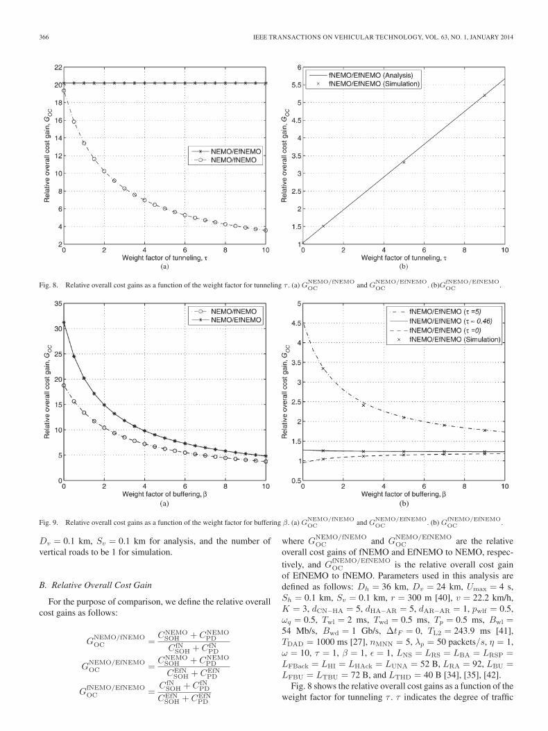
Fig. 8. Relative overall cost gains as a function of the weight factor for tunneling τ . (a) GNEMO/fNEMOOC and G
NEMO/EfNEMOOC . (b)GfNEMO/EfNEMO
OC .
Fig. 9. Relative overall cost gains as a function of the weight factor for buffering β. (a) GNEMO/fNEMOOC and G
NEMO/EfNEMOOC . (b) GfNEMO/EfNEMO
OC .
Dv = 0.1 km, Sv = 0.1 km for analysis, and the number ofvertical roads to be 1 for simulation.
B. Relative Overall Cost Gain
For the purpose of comparison, we define the relative overallcost gains as follows:
GNEMO/fNEMOOC =
CNEMOSOH + CNEMO
PD
CfNSOH + CfN
PD
GNEMO/EfNEMOOC =
CNEMOSOH + CNEMO
PD
CEfNSOH + CEfN
PD
GfNEMO/EfNEMOOC =
CfNSOH + CfN
PD
CEfNSOH + CEfN
PD
where GNEMO/fNEMOOC and G
NEMO/EfNEMOOC are the relative
overall cost gains of fNEMO and EfNEMO to NEMO, respec-tively, and G
fNEMO/EfNEMOOC is the relative overall cost gain
of EfNEMO to fNEMO. Parameters used in this analysis aredefined as follows: Dh = 36 km, Dv = 24 km, Umax = 4 s,Sh = 0.1 km, Sv = 0.1 km, r = 300 m [40], v = 22.2 km/h,K = 3, dCN−HA = 5, dHA−AR = 5, dAR−AR = 1, pwlf = 0.5,ωq = 0.5, Twl = 2 ms, Twd = 0.5 ms, Tp = 0.5 ms, Bwl =54 Mb/s, Bwd = 1 Gb/s, ΔtF = 0, TL2 = 243.9 ms [41],TDAD = 1000 ms [27], nMNN = 5, λp = 50 packets/s, η = 1,ω = 10, τ = 1, β = 1, ε = 1, LNS = LRS = LBA = LRSP =LFBack = LHI = LHAck = LUNA = 52 B, LRA = 92, LBU =LFBU = LTBU = 72 B, and LTHD = 40 B [34], [35], [42].
Fig. 8 shows the relative overall cost gains as a function of theweight factor for tunneling τ . τ indicates the degree of traffic

RYU et al.: ENHANCED FAST HANDOVER FOR NETWORK MOBILITY IN INTELLIGENT TRANSPORTATION SYSTEMS 367
Fig. 10. Relative overall cost gains as a function of the probability of wireless link failure pwlf . (a)GNEMO/fNEMOOC and G
NEMO/EfNEMOOC .
(b) GfNEMO/EfNEMOOC .
Fig. 11. Relative overall cost gains as a function of the number of MNNs nMNN. (a) GNEMO/fNEMOOC and G
NEMO/EfNEMOOC . (b) GfNEMO/EfNEMO
OC .
density over the link between the PAR and the NAR. Addition-ally, road traffic characteristics can be indirectly expressed by τ .When road traffic is high, the number of vehicles movingbetween the same ARs can increase, so that the link betweenthose ARs can be overloaded. This is because we assumed thatthe number of MNs in an MR and a packet arrival rate for eachMNs are fixed, and an MR moves between ARs. Therefore, τcan imply road traffic characteristics. In Fig. 8(a), fNEMO andEfNEMO outperform NEMO. However, the overall cost gainof fNEMO decreases as τ increases, whereas that of EfNEMOremains almost the same, regardless of τ . This is due to thetunneling cost of fNEMO that incurs high packet delivery cost.Thus, as shown in Fig. 8(b), EfNEMO significantly enhances
the handover performance of fNEMO because it eliminates thetunneling cost of fNEMO.
We further consider the buffering cost to calculate the overallcosts of fNEMO and EfNEMO, which was not usually includedin the performance evaluation in previous studies. Fig. 9(a)shows the relative overall cost gains of fNEMO and EfNEMOto NEMO as a function of the weight factor for buffering β.When β is low, both fNEMO and EfNEMO improve the han-dover performance of NEMO. The overall cost gains of fNEMOand EfNEMO to NEMO decrease as β increases becauseNEMO does not use any buffering. As shown in Fig. 9(b), thehandover performance of EfNEMO improves as β decreaseswhen τ > 0.46, whereas it increases as β increases when τ <
368 IEEE TRANSACTIONS ON VEHICULAR TECHNOLOGY, VOL. 63, NO. 1, JANUARY 2014
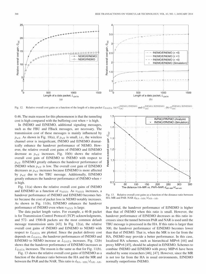
Fig. 12. Relative overall cost gains as a function of the length of a data packet LDATA. (a) GNEMO/fNEMOOC and G
NEMO/EfNEMOOC . (b) GfNEMO/EfNEMO
OC .
0.46. The main reason for this phenomenon is that the tunnelingcost is high compared with the buffering cost when τ is high.
In fNEMO and EfNEMO, additional signaling messages,such as the FBU and FBack messages, are necessary. Thetransmission cost of these messages is mainly influenced bypwlf . As shown in Fig. 10(a), if pwlf is small, i.e., the wirelesschannel error is insignificant, fNEMO and EfNEMO dramat-ically enhance the handover performance of NEMO. How-ever, the relative overall cost gains of fNEMO and EfNEMOdecrease as pwlf increases. Fig. 10(b) shows the relativeoverall cost gain of EfNEMO to fNEMO with respect topwlf . EfNEMO greatly enhances the handover performance offNEMO when pwlf is low. The overall cost gain of EfNEMOdecreases as pwlf increases because EfNEMO is more affectedby pwlf due to the TBU message. Additionally, EfNEMOgreatly enhances the handover performance of fNEMO when τis high.
Fig. 11(a) shows the relative overall cost gains of fNEMOand EfNEMO as a function of nMNN. As nMNN increases, ahandover performance of fNEMO and EfNEMO becomes bet-ter because the cost of packet loss in NEMO notably increases.As shown in Fig. 11(b), EfNEMO enhances the handoverperformance of fNEMO even when nMNN is large.
The data packet length varies. For example, a 40-B packetis for Transmission Control Protocol (TCP) acknowledgments,and 572- and 1500-B packets are the most common defaultmessage transmission units [43]. In Fig. 12(a), the relativeoverall cost gains of fNEMO and EfNEMO to NEMO withrespect to LDATA are plotted. Since the packet delivery costdepends on LDATA, the handover performances of fNEMO andEfNEMO to NEMO increase as LDATA increases. Fig. 12(b)shows that the handover performance of EfNEMO increases asLDATA increases. The reason is the same as that for Fig. 11(b).
Fig. 13 shows the relative overall cost gains of EfNEMO as afunction of the distance ratio between the HA and the MR andbetween the PAR and the NAR. This ratio is dHA−MR/dAR−AR.
Fig. 13. Relative overall cost gains as a function of the distance ratio betweenHA–MR and PAR–NAR dHA−MR/dAR−AR.
In general, the handover performance of EfNEMO is higherthan that of fNEMO when this ratio is small. However, thehandover performance of EfNEMO decreases as this ratio in-creases since the tunnel between PAR and NAR is used until theTBU message is processed in the HA. If this ratio is larger than300, the handover performance of EfNEMO becomes lowerthan that of fNEMO. That is, when the MR is too far from theHA, fNEMO may provide a better performance. In this case,localized HA schemes, such as hierarchical MIPv6 [44] andproxy MIPv6 [45], should be adopted in EfNEMO. Schemes tocombine fNEMO and EfNEMO with proxy MIPv6 have beenstudied by some researchers [46], [47]. However, since the MRis not too far from the HA in usual environments, EfNEMOnormally outperforms fNEMO.

RYU et al.: ENHANCED FAST HANDOVER FOR NETWORK MOBILITY IN INTELLIGENT TRANSPORTATION SYSTEMS 369
Fig. 14. Relative handover latency gains as a function of pwlf . (a) GNEMO/fNEMOHL and G
NEMO/EfNEMOHL . (b) GfNEMO/EfNEMO
HL .
Fig. 15. Relative handover latency gains as a function of ΔtF . (a) GNEMO/fNEMOHL and G
NEMO/EfNEMOHL . (b) GfNEMO/EfNEMO
HL .
C. Relative Handover Latency Gain
To compare the performance of NEMO, fNEMO, andEfNEMO in terms of the handover latency, we define therelative handover latency gains as follows:
GNEMO/fNEMOHL =
TNEMOHL
T fNHL
,
GNEMO/EfNEMOHL =
TNEMOHL
TEfNHL
,
GfNEMO/EfNEMOHL =
T fNHL
TEfNHL
where GNEMO/fNEMOHL and G
NEMO/EfNEMOHL are the relative
handover latency gains of fNEMO and EfNEMO to NEMO,
respectively, and GfNEMO/EfNEMOHL is the relative handover
latency gain of EfNEMO to fNEMO.Fig. 14(a) plots the relative handover latency gains of
fNEMO and EfNEMO to NEMO with respect to pwlf . Whenpwlf is small, fNEMO and EfNEMO outperform NEMO. Therelative handover latency gains of fNEMO and EfNEMO de-crease as pwlf increases because a large value of pwlf increases awireless link delay. As shown in Fig. 14(b), EfNEMO improvesthe handover performance of fNEMO even when pwlf is largebecause EfNEMO uses the wireless link less frequently.
In our numerical results, we assume ΔtF = 0 because thereis good synchronization between the layer-2 and layer-3 han-dovers [34]. However, in practice, there is no way to know theexact time instant when the layer-2 handover begins after theMR receives the FBack message. Thus, we show the impact of

370 IEEE TRANSACTIONS ON VEHICULAR TECHNOLOGY, VOL. 63, NO. 1, JANUARY 2014
ΔtF in terms of the handover latency in Fig. 15. The relativehandover latency gains of fNEMO and EfNEMO to NEMOincrease as ΔtF decreases because a small ΔtF shortens thehandover latency in fNEMO and EfNEMO. When ΔtF >1000 ms, the handover latencies of fNEMO and EfNEMO arelonger than that of NEMO because TDAD = 1000 ms, whichis a critical delay in NEMO. As shown in Fig. 15(b), EfNEMOimproves the handover performance of fNEMO even when ΔtFis large because there is no TREG in EfNEMO.
VI. CONCLUSION
To reduce packet loss and handover latency in NEMO, afast network mobility management protocol for ITS standards,i.e., fNEMO, was proposed in earlier works. We have pointedout that fNEMO has a significant tunneling burden, whichcan cause significant packet loss and handover latency. Toeliminate the tunneling burden of fNEMO, we have proposedEfNEMO, which is an efficient fast handover mechanism forNEMO. We investigated the overall cost and the handoverlatency of EfNEMO. Both our analytical and simulation resultsshow that the handover performance of EfNEMO significantlyoutperforms those of fNEMO and NEMO. We expect thatEfNEMO can be used as an efficient network mobility protocolfor ITS.
REFERENCES
[1] S. Cespedes, X. Shen, and C. Lazo, “IP mobility management for vehicu-lar communication networks: Challenges and solutions,” IEEE Commun.Mag., vol. 49, no. 5, pp. 187–194, May 2011.
[2] K. Zhu, D. Niyato, P. Wang, E. Hossain, and D. I. Kim, “Mobility andhandoff management in vehicular networks: A survey,” Wireless Commun.Mob. Comput., vol. 11, no. 4, pp. 459–476, Apr. 2011.
[3] I. Soto, C. J. Bernardos, M. Calderon, A. Banchs, and A. Azcorra,“NEMO-enabled localized mobility support for Internet access in auto-motive scenarios,” IEEE Commun. Mag., vol. 47, no. 5, pp. 152–159,May 2009.
[4] V. Devarapalli, R. Wakikawa, A. Petrescu, and P. Thubert, Network mo-bility (NEMO) basic support protocol, RFC 3963, Jan. 2005.
[5] T. Ernst, “The information technology era of the vehicular industry,” ACMSIGCOMM Comput. Commun. Rev., vol. 36, no. 2, pp. 49–52, Apr. 2006.
[6] C. Perkins, D. Johnson, and J. Arkko, Mobility support in IPv6, RFC6275, Jul. 2011.
[7] ISO Draft DIS 21210, Intelligent transport systems—Communicationsaccess for land mobiles (CALM)—IPv6 networking, Feb. 2009.
[8] GeoNet Project, Dec. 2011. [Online]. Available: http://www.geonet-project.eu
[9] ETSI TS 102 636-3, v1.1.1, Intelligent Transport Systems (ITS), Ve-hicular communications, GeoNetworking, Part 3: Network architecture,Mar. 2010.
[10] ETSI TS 102 636-4-1,v0.0.9, Intelligent Transport Systems (ITS), Ve-hicular communications, Part 4: Geographical addressing and forwardingfor point-to-point and point-to-multipoint communications, Sub-Part 1:Media-independent functionality, Nov. 2010.
[11] Q. B. Mussabbir, W. Yao, Z. Niu, and X. Fu, “Optimized FMIPv6 usingIEEE 802.21 MIH services in vehicular networks,” IEEE Trans. Veh.Technol., vol. 56, no. 1, pp. 3397–3407, Nov. 2007.
[12] L. Zhong, F. Liu, X. Wang, and Y. Ji, “Fast handover scheme for support-ing network mobility in IEEE 802.16e BWA system,” in Proc. Int. Conf.WiCom, Shanghai, China, 2007, pp. 1757–1760.
[13] S. J. Yoo, S. J. Choi, and D. Su, “Analysis of fast handover mechanismsfor hierarchical mobile IPv6 network mobility,” Wireless Pers. Commun.,vol. 48, no. 2, pp. 215–238, Jan. 2009.
[14] L. Qingbo, Z. Xuejun, and Z. Liang, “A mobility management mechanismin aeronautical telecommunication network,” in Proc. IET Int. CCWMC,2009, pp. 594–597.
[15] B. A. Mohammed and T. C. Wan, “Modified fast-integrated light-NEMOv6 handoff in IEEE 802.16e BWA networks,” in Proc. 2nd Int.Conf. NETAPPS, 2010, pp. 182–187.
[16] R. Chaki and N. G. Niyogi, “An improved scheme towards fast handoverin a hierarchical mobile network,” in Proc. URSI General Assembly Sci.Symp., 2011, pp. 1–4.
[17] RFC 5568, Mobile IPv6 Fast Handovers, Jul. 2009.[18] M. Calderon, C. J. Bernardos, M. Bagnulo, I. Soto, and A. de la Oliva,
“Design and experimental evaluation of a route optimization solution forNEMO,” IEEE J. Sel. Areas Commun., vol. 24, no. 9, pp. 1702–1716,Sep. 2006.
[19] H. Petander, E. Perera, K.-C. Lan, and A. Seneviratne, “Measuring andimproving the performance of network mobility management in IPv6networks,” IEEE J. Sel. Areas Commun., vol. 24, no. 9, pp. 1671–1681,Sep. 2006.
[20] I. C. Chang and C. H. Chou, “HCoP-B: A hierarchical care-of prefix withBUT scheme for nested mobile networks,” IEEE Trans. Veh. Technol.,vol. 58, no. 6, pp. 2942–2965, Jul. 2009.
[21] S. Pack, T. Kwon, Y. Choi, and E. Paik, “An adaptive network mobilitysupport protocol in hierarchical mobile IPv6 networks,” IEEE Trans. Veh.Technol., vol. 58, no. 7, pp. 3627–3639, Sep. 2009.
[22] C. M. Huang, C. H. Lee, and J. R. Zheng, “A novel SIP-based routeoptimization for network mobility,” IEEE J. Sel. Areas Commun., vol. 24,no. 9, pp. 1682–1691, Sep. 2009.
[23] H. J. Lim, M. Kim, J. H. Lee, and T. M. Chung, “Route optimization innested NEMO: Classification, evaluation, and analysis from NEMO fringestub perspective,” IEEE Trans. Mobile Comput., vol. 8, no. 11, pp. 1554–1572, Nov. 2009.
[24] A. Z. M. Shahriar, M. Atiquzzaman, and W. Ivancic, “Route optimizationin network mobility: Solutions, classification, comparison, and future re-search directions,” IEEE Commun. Surveys Tut., vol. 12, no. 1, pp. 24–38,1st Quarter, 2010.
[25] S. Ryu and Y. Mun, “The tentative and early binding update for mobileIPv6 fast handover,” in Proc. MSN, vol. 3794, Lecture Notes Comput.Sci., Dec. 2005, pp. 825–835.
[26] S. Ryu and Y. Mun, “A scheme to enhance TEBU scheme of fasthandovers for mobile IPv6,” in Proc. Int. Conf. Embedded Soft-ware and Systems, vol. 4523, Lecture Notes Comput. Sci., May 2007,pp. 773–782.
[27] S. Thomson, T. Narten, and T. Jinmei, IPv6 stateless address autoconfig-uration, RFC 4862, Sep. 2007.
[28] T. Camp, J. Boleng, and V. Davies, “A survey of mobility models for adhoc network research,” Wireless Commun. Mobile Comput., vol. 2, no. 5,pp. 483–502, Aug. 2002.
[29] V. Davies, “Evaluating mobility models within and ad hoc network,” M.S.thesis, Dept. Math. Comput., Colorado School of Mines, Golden, CO,USA, 2000.
[30] M. S. Hossain and M. Atiquzzaman, “Cost analysis of mobility proto-cols,” Telecommun. Syst., vol. 52, no. 4, pp. 2271–2285, Apr. 2013.
[31] M. S. Hossain and M. Atiquzzaman, “Stochastic properties and applica-tion of city section mobility model,” in Proc. IEEE GLOBECOM, 2009,pp. 1–6.
[32] S. Ryu, K. Lee, and Y. Mun, “Optimized fast handover scheme in mobileIPv6 networks to support mobile users for cloud computing,” J. Super-comput., vol. 59, no. 2, pp. 658–675, Feb. 2012.
[33] Y. -B. Lin, “Modeling techniques for large-scale PCS networks,” IEEECommun. Mag., vol. 35, no. 2, pp. 102–107, Feb. 1997.
[34] C. Makaya and S. Pierre, “An analytical framework for performanceevaluation of IPv6-based mobility management protocols,” IEEE Trans.Wireless Commun., vol. 7, no. 3, pp. 972–983, Mar. 2008.
[35] J. McNair, I. F. Akyildiz, and M. D. Bender, “An inter-systemhandoff technique for the IMT-2000 system,” in Proc. INFOCOM, 2000,pp. 208–216.
[36] J. Xie and I. F. Akyldiz, “A novel distributed dynamic location manage-ment scheme for minimizing signaling costs in mobile IP,” IEEE Trans.Mobile Comput., vol. 1, no. 3, pp. 163–175, Jul.–Sep. 2002.
[37] N. Aschenbruck, R. Ernst, E. Gerhards-Padilla, and M. Schwamborn,“BonnMotion—A mobility scenario generation and analysis tool,” inProc. SIMUTools, Torremolinos, Spain, 2010, pp. 1–10.
[38] Seoul Metropolitan Government. Report on velocity of vehicles in Seoul2010. [Online]. Available: http://traffic.seoul.go.kr/wp-content/themes/seoul_traffic/data/2010_3.pdf
[39] Seoul Expressway Traffic Control Center. Seoul Expressway Traffic In-formation. 2012. [Online]. Available: http://smartway.seoul.go.kr/english/index.html
[40] J. T. Park and S. M. Chun, “Fast mobility management for delay-sensitiveapplications in vehicular networks,” IEEE Commun. Lett., vol. 15, no. 1,pp. 31–33, Jan. 2011.
[41] S. Pack, J. Choi, T. Kwon, and Y. Choi, “Fast-handoff support in IEEE802.11 wireless networks,” IEEE Commun. Surveys Tut., vol. 9, no. 1,pp. 2–12, 1st Quart., 2007.
RYU et al.: ENHANCED FAST HANDOVER FOR NETWORK MOBILITY IN INTELLIGENT TRANSPORTATION SYSTEMS 371
[42] J. McNair, I. F. Akyildiz, and M. D. Bender, “Handoffs for real-time trafficin mobile IP version 6 networks,” in Proc. IEEE GLOBECOM, 2001,pp. 3463–3467.
[43] C. Fraleigh, S. Moon, B. Lyles, C. Cotton, M. Khan, D. Moll, R. Rockell,T. Seely, and C. Diot, “Packet-level traffic measurements from the SprintIP backbone,” IEEE Netw., vol. 17, no. 6, pp. 6–16, Nov./Dec. 2003.
[44] H. Soliman, C. Castelluccia, K. ElMalki, and L. Bellier, Hierarchicalmobile IPv6 (HMIPv6) mobility management, RFC 5380, Oct. 2008.
[45] S. Gundavelli, K. Leung, V. Devarapalli, K. Chowdhury, and B. Patil,Proxy mobile IPv6, RFC 5213, Aug. 2008.
[46] J. H. Lee, T. Ernst, and N. Chilamkurti, “Performance analysis of PMIPv6based network mobility for intelligent transportation systems,” IEEETrans. Veh. Technol., vol. 61, no. 1, pp. 74–85, Jan. 2012.
[47] S. Ryu, J.-W. Choi, and K.-J. Park, “A scheme improving fast PMIPv6-based network mobility by eliminating tunneling overload for ITS,” inProc. IEEE IV Symp., Jun. 2012, pp. 1–6.
Seonggeun Ryu received the B.S. degree incomputer science from Yonsei University, Seoul,Korea, in 2002 and the M.S. and Ph.D. degreesfrom Soongsil University, Seoul, in 2006 and 2011,respectively.
From 2011 to 2013, he was a Postdoctoral Re-searcher with the Department of Information andCommunication Engineering, Daegu Gyeongbuk In-stitute of Science and Technology, Daegu, Korea. Heis currently with LG Electronics, Seoul, Korea. Hisresearch interests include analyzing, modeling, im-
proving, and securing Internet-Protocol-based mobility management protocolsfor next-generation wireless networks and vehicular networks.
Kyung-Joon Park (S’01–M’05) received the B.S.and M.S. degrees in electrical engineering and thePh.D. degree in electrical engineering and com-puter science from Seoul National University, Seoul,Korea.
From 2001 to 2002, he was a Visiting GraduateStudent with the Department of Electrical and Com-puter Engineering, University of Illinois at Urbana-Champaign (UIUC), Urbana, IL, USA. From 2005to 2006, he was a Senior Engineer with SamsungElectronics, Suwon, Korea. From 2006 to 2010, he
was a Postdoctoral Research Associate with the Department of ComputerScience, UIUC. He is currently an Assistant Professor with the Department ofInformation and Communication Engineering, Daegu Gyeongbuk Institute ofScience and Technology, Daegu, Korea. His current research interests includemodeling and analysis of cyber–physical systems and the design of medical-grade protocols for wireless healthcare systems.
Dr. Park is currently serving on the editorial boards of the Wiley Transactionson Emerging Telecommunications Technologies. He has served as a Lead GuestEditor for a special issue on cyber–physical systems in Computer Commu-nications. He has also served as a program committee member of numerousinternational conferences on wireless networking. He received the Gold Prizeat the Samsung InsideEdge Thesis Competition.
Ji-Woong Choi (S’00–M’04–SM’09) received theB.S., M.S., and Ph.D. degrees in electrical engineer-ing from Seoul National University (SNU), Seoul,Korea, in 1998, 2000, and 2004, respectively.
From 2004 to 2005, he was a PostdoctoralResearcher with the Interuniversity SemiconductorCenter, SNU. From 2005 to 2007, he was withthe Department of Electrical Engineering, StanfordUniversity, Stanford, CA, USA, as a PostdoctoralVisiting Scholar. From 2006 to 2007, he also workedas a Consultant with GCT Semiconductor, San Jose,
CA, USA, on the development of mobile TV receivers. From 2007 to October2010, he was with Marvell Semiconductor, Santa Clara, CA, USA, as aStaff Systems Engineer for next-generation wireless communication systems,including Worldwide Interoperability for Microwave Access and Long-TermEvolution. Since October 2010, he has been with the Department of Informationand Communication Engineering, Daegu Gyeongbuk Institute of Science andTechnology, Daegu, Korea, as an Assistant Professor. His research interestsinclude wireless communication theory, signal processing, biomedical commu-nication applications, and brain–machine interfaces.
Dr. Choi received the Silver Award at the Samsung Humantech Paper Contestin February 2005 and the IT National Scholarship from the Korean Ministry ofInformation and Communication in October 2005.