enhanced oil recovery
DESCRIPTION
articleTRANSCRIPT

Enhanced oil recovery techniques
Dinesh C Tewari
Institute of Reservoir Studies Oil and Natural Gas Corporation Limited
Ahmedabad
22 December 2009 Sivasagar

WHAT COMES TO MIND WHEN THE PRODUCTION OF YOUR WELLS
START TO DECLINE?
What is the purpose of Enhanced Oil Recovery?
• EOR is intended to improve –– displacement efficiency (at pore level)– sweep efficiency (vertical and areal)• Reduction of residual oil saturation isthe key to improving displacementefficiency, which is determined by theCapillary Number

Primary Recovery
Secondary Recovery
Tertiary Recovery
ChemicalThermal Gas


PRIMARY AND SECONDARY RECOVERY
After primary and secondary recovery (waterflood) oil remains in the reservoir as:
� uncontacted (unswept) oil (So = 1 - Swi)
� partially removed oil (1 - Swi < So > Soi)
� residual oil (So = Soi)
Secondary and tertiary recovery are together referred to as enhanced oil recovery (EOR).

Incremental IOR/EOR Oil by means of : IOR Improved Mobility ratioIOR Improved Areal SweepIOR Improved Vertical SweepEOR Lower Residual Oil Saturation
Incremental IOR/EOR Oil

Thermal EOR Methods
THERMAL
Hot Water Steam In-Situ Elec. Heat
CSS SteamFlood SAGD Conductive
Heating Forward Reverse Hi Press.Air Inj.
Frac
Non-Frac
VAPEX
VAPEX + Steam
SAGP
Dry
Wet
W / Additives
THAI
CAPRI

Thermal EOR Process Thermal EOR Process
The principle of thermal EOR is that heat increases the mobilityThe principle of thermal EOR is that heat increases the mobility of of oil by reducing the viscosity. oil by reducing the viscosity.
Oil mobility is increased relative to that of water and the mobility ratio is reduced allowing more favourable displacement.

Thermal EOR Process
•Steam Flooding Process: In this process, steam is continuously introduced into an injection well. When steam is injected into the reservoir, heat is transferred to the oil bearing formation, reservoir fluids and some of the adjacent cap and base rock. The heat reduces the oil viscosity. This increases the mobility of oil.
•As the steam loses heat energy it condenses to yield a mixture of steam and hot water. Because of pressure gradient towards producing well, an oil bank is formed ahead of steam zone. This enables the immobile oil to get produced from the reservoir. In general steam reduces the oil saturation in the steam zone to very low value (about 10±%. Some oil is also transported by steam distillation.

Thermal (Steam flooding)

Thermal EOR Process Thermal EOR Process
Technical Screening GuidelinesTechnical Screening GuidelinesCrude OilCrude OilGravityGravity : <36: <36oo APIAPIViscosityViscosity : > 20cP: > 20cPComposition: Not critical but some light ends for steam Composition: Not critical but some light ends for steam distillation will help.distillation will help.ReservoirReservoirType of formation : Sand or sand stone with high Type of formation : Sand or sand stone with high porosity and Permeability preferredporosity and Permeability preferredNet Thickness : >15 feetNet Thickness : >15 feetAverage permeability : >10mDAverage permeability : >10mDDepthDepth : 300: 300--5000 ft5000 ftTemperatureTemperature : Not Critical: Not Critical

Limitations :Limitations :••Oil saturation must be high, and the pay zone should be Oil saturation must be high, and the pay zone should be more than 15ft thick to minimize the heat losses to more than 15ft thick to minimize the heat losses to adjacent formations.adjacent formations.
••Lighter, less viscous crude oils can be steam flooded, but Lighter, less viscous crude oils can be steam flooded, but normally they are not if reservoir responds to an ordinary normally they are not if reservoir responds to an ordinary water flood.water flood.
••Steam flooding is primarily applicable to viscous oil in Steam flooding is primarily applicable to viscous oil in massive, high permeability sandstones or unconsolidated massive, high permeability sandstones or unconsolidated sands.sands.
Thermal EOR Process Thermal EOR Process

Limitations :Limitations :••Steam flooded reservoirs should be as shallow as possible Steam flooded reservoirs should be as shallow as possible as long as pressure for sufficient injection rates can be as long as pressure for sufficient injection rates can be maintained. This is to avoid excessive heat losses in the maintained. This is to avoid excessive heat losses in the well bore.well bore.••Steam flooding is not normally used in carbonate reservoir.Steam flooding is not normally used in carbonate reservoir.••Cost per incremental barrel of oil is high.Cost per incremental barrel of oil is high.••Low percentage of waterLow percentage of water--sensitive clays is desired for sensitive clays is desired for good good injectivityinjectivity..••Adverse mobility ratio and channeling of steam may make Adverse mobility ratio and channeling of steam may make this process unattractive.this process unattractive.
Thermal EOR Process Thermal EOR Process

Steam Flooding (Huff and Puff)

Steam Assisted Gravity Drainage
Horizontal wells drilled in stacked pairs form the basic unit of SAGD project (top). Steam injected into the upper well melts surrounding oil (bottom). Gravity causes the mobilized oil to flow downward to the lower well for production.

Thermal EOR Process Thermal EOR Process InIn--situ Combustion Processsitu Combustion Process
This process involves starting a fire in the reservoir and injecThis process involves starting a fire in the reservoir and injecting ting air to sustain the burning of some of the crude oil, usually in air to sustain the burning of some of the crude oil, usually in combination with water. A combustion front is formed at which combination with water. A combustion front is formed at which the injected air burns a small portion of the reservoir oil. Thethe injected air burns a small portion of the reservoir oil. Theprocess combustion can be achieved through low temperature process combustion can be achieved through low temperature oxidation and high temperature oxidation. Low temperature oxidation and high temperature oxidation. Low temperature oxidation is suited for light oil. Hot flue gas and steam resultoxidation is suited for light oil. Hot flue gas and steam resulting ing from combustion and water vaporization displace the oil ahead from combustion and water vaporization displace the oil ahead of the combustion front. Vaporization of the light ends and of the combustion front. Vaporization of the light ends and thermal cracking also occur. Ahead of the combustion front, the thermal cracking also occur. Ahead of the combustion front, the vaporized light ends condense, providing some assistance to vaporized light ends condense, providing some assistance to displacement by solvent dilution of the virgin crude.displacement by solvent dilution of the virgin crude.

Thermal EOR Process Thermal EOR Process


SCHEMATIC OF SPONTANEOUS IGNITION
Bridge Plug
Air injection
Spontaneous IgnitionSpontaneous Ignition

SCHEMATIC OF ARTIFICIAL IGNITION
Bridge Plug
Gas Injection
Air injection
TEB port for loading TEB
Gas BurnerGas Burner

InIn--situ Combustionsitu Combustion

Thermal EOR ProcessThermal EOR ProcessTechnical Screening GuidelinesTechnical Screening GuidelinesCrude Oil Crude Oil GravityGravity : <48o API: <48o APIViscosityViscosity : < 100cP: < 100cPComposition: Some Composition: Some asphalticasphaltic components to aid coke components to aid coke deposition.deposition.ReservoirReservoirType of formation : Sand or sand stone with high Type of formation : Sand or sand stone with high porosity and permeability preferredporosity and permeability preferredNet Thickness : >15 feetNet Thickness : >15 feetAverage flow capacity : > 20 Average flow capacity : > 20 mDmD--ftftDepthDepth : > 500 ft: > 500 ftTemperatureTemperature : 150oF preferred: 150oF preferred

Thermal EOR ProcessThermal EOR ProcessLimitationsLimitationsThe process will not sustain if sufficient coke is not depositedThe process will not sustain if sufficient coke is not deposited..
Excessive deposition of coke will lead to low advancement of Excessive deposition of coke will lead to low advancement of combustion front and eventually killing of the process in the prcombustion front and eventually killing of the process in the presence esence of sufficient quantity of air.of sufficient quantity of air.
Oil saturation and porosity must be high to minimize heat loss tOil saturation and porosity must be high to minimize heat loss to rock.o rock.Produced flue gases can pose environmental problem.Produced flue gases can pose environmental problem.
Operation problems such as severe corrosion caused by low pH hotOperation problems such as severe corrosion caused by low pH hotwater, increased sand production, pipe failures as a result of hwater, increased sand production, pipe failures as a result of high igh temperature and adverse mobility ratio makes this process temperature and adverse mobility ratio makes this process complicated and difficult.complicated and difficult.
Heterogeneous formation can result in poor sweep efficiency.Heterogeneous formation can result in poor sweep efficiency.

ISC Pilot Project : ISC Pilot Project : BechrajiBechrajiNo. of Flowing wellsNo. of Flowing wells :: 121121Air Injectors on streamAir Injectors on stream :: 44Air Injection Rate, Nm3/d:Air Injection Rate, Nm3/d: 100000100000Cum. Air Injection, Cum. Air Injection, NMMm3NMMm3 :: 6060Oil rate, tpdOil rate, tpd :: 2222Water Cut, %Water Cut, % :: 5555Primary recoveryPrimary recovery : : 10%10%Recovery with EORRecovery with EOR :: 45%45%
0
200
400
600
800
1000
Nov
-85
Nov
-86
Nov
-87
Nov
-88
Nov
-89
Nov
-90
Nov
-91
Nov
-92
Nov
-93
Nov
-94
Nov
-95
Nov
-96
Nov
-97
Nov
-98
Nov
-99
Nov
-00
Nov
-01
Nov
-02
Nov
-03
Nov
-04
Nov
-05
Nov
-06
Nov
-07
Oil
rate
, tpd
0
20
40
60
80
100
W/c
, %Oil Rate
W/C
Inititiation of ISC
0
200
400
600
800
1000
Nov
-85
Nov
-86
Nov
-87
Nov
-88
Nov
-89
Nov
-90
Nov
-91
Nov
-92
Nov
-93
Nov
-94
Nov
-95
Nov
-96
Nov
-97
Nov
-98
Nov
-99
Nov
-00
Nov
-01
Nov
-02
Nov
-03
Nov
-04
Nov
-05
Nov
-06
Nov
-07
Oil
rate
, tpd
0
20
40
60
80
100
W/c
, %Oil Rate
W/C
Inititiation of ISC
Dri
ve-
Act
ive
Bott
om W
ater
RF
-10
.2 %
Visc
ocit
y-
300
cp

Balol FieldBalol Field
In-situ combustion pilot : March 1990
Semi-commercial Phase : Jan. 1992
Commercial Phase : Oct. 1997
Primary Recovery : ~ 10 %
Envisaged additional recovery : 36 % :~ 6.57 MMt
0
200
400
600
800
1000
Nov
-85
Nov
-86
Nov
-87
Nov
-88
Nov
-89
Nov
-90
Nov
-91
Nov
-92
Nov
-93
Nov
-94
Nov
-95
Nov
-96
Nov
-97
Nov
-98
Nov
-99
Nov
-00
Nov
-01
Nov
-02
Nov
-03
Nov
-04
Nov
-05
Nov
-06
Nov
-07
Oil
rate
, tpd
0
20
40
60
80
100
W/c
, %Oil Rate
W/C
Inititiation of ISC
Dri
ve-
Act
ive
Edge
Wat
er
RF
-44
.8 %
( P
R-13
%)
Visc
ocit
y-
150
to 1
000
cp

Santhal FieldSanthal Field
Commercial Phase : Oct. 1997
Primary Recovery : ~17 %
Envisaged additional recovery: 30 % : 14.57MMt
0
500
1000
1500
2000
Jun-
74
Jun-
76
Jun-
78
Jun-
80
Jun-
82
Jun-
84
Jun-
86
Jun-
88
Jun-
90
Jun-
92
Jun-
94
Jun-
96
Jun-
98
Jun-
00
Jun-
02
Jun-
04
Jun-
06
Jun-
08
Jun-
10
Jun-
12
TIME------>
OIL
T/d
ay---
---->
Oil Gain by EOR = 1.122 MMt Till Aug '04
ACTUALENVISAGED PRIMARY RECOVERY
OIL GAIN BY EOR (IN-SITU COMBUSTION) IN SANTHAL FIELD
START OF ISC
EOR
Dri
ve-
Act
ive
Edge
Wat
er
RF
-42
.8 %
( P
R-17
%)
Visc
ocit
y-
50 t
o 15
0 cp

Non-Thermal EOR Methods
NON-THERMAL
Miscible Chemical Imm. GasDrives Other
Flue Gas
CO2
Inert Gas
FOAM
MEOR
Surfactant
Polymer
Alkaline
Enriched Gas Drive
Slug Process
N2 Miscible
CO2 Miscible
Alcohol
ASP
Micellar
Emulsion
Vaporizing Gas Drive

Chemical EOR Process Chemical EOR Process
100
8477
63 6151
4026 24
12 10 10 9 7 6 4 4 3 3
173
0.3 0.20.60.90
20
40
60
80
100
120
140
160
180
S. A
rabi
a
US
A
Iran
Iraq
Kuw
ait
Abu
Dha
bi
Ven
ezue
la
Rus
sia
Liby
a
Nig
eria
Chi
na
Qat
ar
Mex
ico
Can
ada
Bra
zil
Nor
way
Om
an
Indi
a
UK
Dub
ai
Den
mar
k
Rom
ania
Ger
man
y
Fran
ce
Bill
ion
Bbl
s
Assumed: Primary Rec. 33.3 %OOIP Chem. Flood Rec. 33.3 %OIP

Chemical Floods Current Status WorldwideChemical Floods Current Status Worldwide
C h in a
Ve n e zu e la
F ra n c e
In d iaIn d o n e s ia US A
Total N u m b er of P rojects : 27

Chemical EOR Process Chemical EOR Process OBJECTIVES OF CHEMICAL FLOODING
• Increase the Capillary Number Nc to mobilize residual oil• Decrease the Mobility Ratio M for better sweep• Emulsification of oil to facilitate production
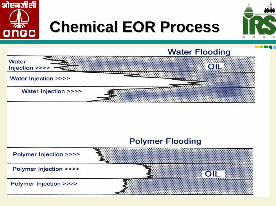
The process also called as The process also called as micellarmicellar or micro emulsion flooding, or micro emulsion flooding, consists of injecting a slug that contains surfactant, coconsists of injecting a slug that contains surfactant, co--surfactants, oil, water and other chemicals. The function of thesurfactants, oil, water and other chemicals. The function of thesurfactant is to reduce oil/water interfacial tension, but it masurfactant is to reduce oil/water interfacial tension, but it may y also cause inter phase mass transfer of reservoir oil and water.also cause inter phase mass transfer of reservoir oil and water.Both the inter phase mass transfer and reduction of IFT increaseBoth the inter phase mass transfer and reduction of IFT increaserecovery of oil. Surfactant slug is often followed by polymer recovery of oil. Surfactant slug is often followed by polymer thickened water to improve sweep efficiency.thickened water to improve sweep efficiency.

Chemical EOR Process Chemical EOR Process

WATER FLOODWATER FLOOD
InjectorInjector ProducerProducer

WATER FLOODWATER FLOOD
InjectorInjector ProducerProducer

WATER FLOODWATER FLOOD
InjectorInjector ProducerProducer

WATER FLOODWATER FLOOD
InjectorInjector ProducerProducer

WATER FLOODWATER FLOOD
InjectorInjector ProducerProducer

SURFACTANT FLOOD
Surfactant follows the water channels through the formation

SURFACTANT FLOODSURFACTANT FLOOD
InjectorInjector ProducerProducer

SURFACTANT FLOODSURFACTANT FLOOD
InjectorInjector ProducerProducer

SURFACTANT FLOODSURFACTANT FLOOD
InjectorInjector ProducerProducer

SURFACTANT FLOODSURFACTANT FLOOD
InjectorInjector ProducerProducer

SURFACTANT FLOODSURFACTANT FLOOD
InjectorInjector ProducerProducer

SMART SURFACTANT™ FLOOD
Smart Surfactant seeks out oil-bearing channels, blocks water channels

SMART SURFACTANTSMART SURFACTANT
InjectorInjector ProducerProducer

SMART SURFACTANT™SMART SURFACTANT™
InjectorInjector ProducerProducer

SMART SURFACTANT™SMART SURFACTANT™
InjectorInjector ProducerProducer

SMART SURFACTANT™SMART SURFACTANT™
InjectorInjector ProducerProducer

SMART SURFACTANT™SMART SURFACTANT™
InjectorInjector ProducerProducer

SMART SURFACTANT™SMART SURFACTANT™
InjectorInjector ProducerProducer

SMART SURFACTANT™SMART SURFACTANT™
InjectorInjector ProducerProducer

Chemical EOR Process Chemical EOR Process

Chemical EOR Process Chemical EOR Process Technical Screening GuidelinesTechnical Screening GuidelinesCrude OilCrude OilGravityGravity : > 20o API: > 20o APIViscosityViscosity : < 100 : < 100 cPcPComposition: Light intermediates are desirableComposition: Light intermediates are desirableReservoirReservoirType of formation : Sand stone preferredType of formation : Sand stone preferredNet Thickness : > 10ft Net Thickness : > 10ft Average permeability : > 10mDAverage permeability : > 10mDDepthDepth : 950 to 9000 ft( temperature!): 950 to 9000 ft( temperature!)
TemperatureTemperature : <200o F: <200o F


Chemical EOR Process Chemical EOR Process LimitationsLimitations
••Adsorption of chemicals can be detrimental to the process.Adsorption of chemicals can be detrimental to the process.High temperature leads to degradation of chemicals.High temperature leads to degradation of chemicals.
••Best results are obtained when alkaline material reacts with cruBest results are obtained when alkaline material reacts with crude oil. de oil. The oil should have acid number more than 0.2 mg KOH/g of oil.The oil should have acid number more than 0.2 mg KOH/g of oil.
••High amounts of anhydrite, gypsum or clays are undesirable.High amounts of anhydrite, gypsum or clays are undesirable.
••Formation water chloride of < 20,000 Formation water chloride of < 20,000 ppmppm and divalent ions (Ca++ and divalent ions (Ca++ and Mg++) <500 and Mg++) <500 ppmppm are desirable.are desirable.
••High heterogeneity may lead to the failure of the process.High heterogeneity may lead to the failure of the process.Vertical fractures may lead to gravity segregation.Vertical fractures may lead to gravity segregation.

Chemical EOR Process Chemical EOR Process Polymer ProcessPolymer Process
The objective of polymer flooding is to provide better The objective of polymer flooding is to provide better displacement and volumetric sweep efficiencies during a displacement and volumetric sweep efficiencies during a water flood. They do not lower the residual oil saturation. water flood. They do not lower the residual oil saturation. They improve recovery by increasing the viscosity of They improve recovery by increasing the viscosity of water, decreasing the mobility of water, contacting a large water, decreasing the mobility of water, contacting a large volume of the reservoir and reducing the injected fluid volume of the reservoir and reducing the injected fluid mobility to improve aerial and vertical sweep efficiencies. mobility to improve aerial and vertical sweep efficiencies. Because, polymer flooding inhibits fingering, the oil Because, polymer flooding inhibits fingering, the oil displacement is more efficient in the early stages as displacement is more efficient in the early stages as compared to a conventional watercompared to a conventional water--floodflood

Chemical EOR Process Chemical EOR Process

Chemical EOR Process Chemical EOR Process
Chemical EOR Process Chemical EOR Process

Chemical EOR Process Chemical EOR Process

Chemical EOR Process Chemical EOR Process Technical Screening GuidelinesTechnical Screening GuidelinesCrude OilCrude OilGravityGravity : > 15o API: > 15o APIViscosityViscosity : <200 : <200 cPcPCompositionComposition : Not critical: Not criticalReservoirReservoirType of formation : Sand stone preferredType of formation : Sand stone preferredNet Thickness : > 10ft Net Thickness : > 10ft Average permeability : > 10mDAverage permeability : > 10mDDepthDepth : < 9000 ft( temperature!): < 9000 ft( temperature!)
TemperatureTemperature : < 229o : < 229o

Chemical EOR Process Chemical EOR Process Limitations and FactsLimitations and Facts
••There are two types polymer synthetically produced polymers There are two types polymer synthetically produced polymers ((AcrylamideAcrylamide type) and biotype) and bio--polymers (polymers (XanthumXanthum gum).gum).••Factors which degrade polymers are salinity, temperature, time, Factors which degrade polymers are salinity, temperature, time, shear rate and presence of divalent ions.shear rate and presence of divalent ions.••BioBio--polymers suffer from bacterial degradation and cause well bore polymers suffer from bacterial degradation and cause well bore plugging.plugging.••Polymers may be ineffective in a mature water flood because of lPolymers may be ineffective in a mature water flood because of low ow mobile oil saturation.mobile oil saturation.••High adsorption on reservoir rock may kill the process.High adsorption on reservoir rock may kill the process.••Optimum temperature is a key selection criterion for polymers. COptimum temperature is a key selection criterion for polymers. Clay lay increase polymer adsorption.increase polymer adsorption.••If oil viscosities are high, a higher polymer concentration is nIf oil viscosities are high, a higher polymer concentration is needed eeded to achieve the desired mobility control.to achieve the desired mobility control.••Some heterogeneity is acceptable but for conventional polymer Some heterogeneity is acceptable but for conventional polymer flooding, reservoirs with extensive fractures should be avoided.flooding, reservoirs with extensive fractures should be avoided.

Polymer Flood: SanandPolymer Flood: SanandInjectors : Injectors : Polymer Polymer -- 13, Chase Water 13, Chase Water -- 77
Injection Rate : 910m3/d (800ppm) , 490m3/d (Water)Injection Rate : 910m3/d (800ppm) , 490m3/d (Water)
Envisaged addl. Recovery:Envisaged addl. Recovery: ~ 14 %~ 14 %
Dri
ve-
Act
ive
Edge
Wat
er
RF
-31
.5 %
Visc
ocit
y-
20 c
p

Polymer Flood: SanandPolymer Flood: Sanand
0
50
100
150
200
250
300
350
400
450
500
5/1/
1969
6/1/
1970
7/1/
1971
8/1/
1972
9/1/
1973
10/1
/197
411
/1/1
975
12/1
/197
61/
1/19
782/
1/19
793/
1/19
804/
1/19
815/
1/19
826/
1/19
837/
1/19
848/
1/19
859/
1/19
8610
/1/1
987
11/1
/198
812
/1/1
989
1/1/
1991
2/1/
1992
3/1/
1993
4/1/
1994
5/1/
1995
6/1/
1996
7/1/
1997
8/1/
1998
9/1/
1999
10/1
/200
011
/1/2
001
12/3
1/20
021/
31/2
004
2/28
/200
53/
31/2
006
Oil
rate
(m3 /d
)
0
20
40
60
80
100
120
140
wat
er c
ut (%
)

Jhalora
Drive- Active Edge Water
RF - 36.6 %
Viscocity - 5-35 cp

Gas Based EOR Process Gas Based EOR Process
Gas Based EOR Process Gas Based EOR Process
Gas Injection is the second largest enhanced oil recovery process, next only to thermal processes used in heavy oil fields. The residual oil saturations in gas swept zones have been found to be quite low, however, the volumetric sweep of the flood has always been a cause of concern. The mobility ratio, which controls the volumetric sweep, between the injected gas and displaced oil bank in gas processes, is typically highly unfavorable due to the relatively low viscosity of the injected phase. This difference makes mobility and consequently flood profile control the biggest concerns for the successful application of this process.

Gas Contribution to Green House Effect

Gas Based EOR Process Gas Based EOR Process
Miscible & immiscible gas injection processMiscible & immiscible gas injection process
In miscible gas injection process mass transfer occur between In miscible gas injection process mass transfer occur between oil & gas & forms a transition zone to displace the oil effectivoil & gas & forms a transition zone to displace the oil effectively.ely.
Miscible gas injection gives better displacement efficiency.Miscible gas injection gives better displacement efficiency.
Immiscible gas injection improves recovery by swelling & oil Immiscible gas injection improves recovery by swelling & oil viscosity reduction.viscosity reduction.
Displacement efficiency of immiscible gas injection is less thenDisplacement efficiency of immiscible gas injection is less thenmiscible gas injection process.miscible gas injection process.

Gas Based EOR Process Gas Based EOR Process
Hydrocarbon Miscible FloodingHydrocarbon Miscible Flooding ::
Hydrocarbon miscible flooding consists of injecting light Hydrocarbon miscible flooding consists of injecting light hydrocarbons through the reservoir to form a miscible flood. Thehydrocarbons through the reservoir to form a miscible flood. Theprocess recovers crude oil by generating miscibility (in the process recovers crude oil by generating miscibility (in the condensing and vaporizing gas drive), increasing oil volume by condensing and vaporizing gas drive), increasing oil volume by swelling and decreasing the viscosity of oil. Three different meswelling and decreasing the viscosity of oil. Three different methods thods of attaining miscibility are used. One method uses about 5% PV sof attaining miscibility are used. One method uses about 5% PV slug lug of liquefied petroleum gas such as propane, followed by natural of liquefied petroleum gas such as propane, followed by natural gas gas or gas and water. A second method called enriched (condensing) or gas and water. A second method called enriched (condensing) gas drive , consists of injecting 10 to 20% PV slug of natural ggas drive , consists of injecting 10 to 20% PV slug of natural gas as that is enriched with ethane through hexane(C2 to C6) , followedthat is enriched with ethane through hexane(C2 to C6) , followed by by lean gas and possible water. lean gas and possible water.

Gas Based EOR Process Gas Based EOR Process
Overall displacement EfficiencyOverall displacement EfficiencyE = Es x E = Es x EiEi x Edx Ed
Where Es is Where Es is arealareal sweep efficiencysweep efficiencyEiEi is invasion efficiency or vertical sweep efficiencyis invasion efficiency or vertical sweep efficiencyEd is microscopic displacement efficiency which accounts for theEd is microscopic displacement efficiency which accounts for thetrapping of oil by capillary forces in the pores invaded by trapping of oil by capillary forces in the pores invaded by displacing fluid.displacing fluid.

Miscible Gas Flooding (Hydrocarbon Injection)
In jec t ionWell
WaterIn jec t ion
Pum p
Sep ar a t ion andSto r ag e Fac il i t ies Pr o d u c t io n Well
1 2Oil Zo ne O il B ank /Misc ib le Fr on t
4 13 2
3 H C andWater Zone 4 Dr ive Water
H C GasIn jec t ionfr om Pip e lin eo r Rec yc le

Gas Based EOR Process Gas Based EOR Process Hydrocarbon Miscible Flooding :Hydrocarbon Miscible Flooding :
The enriching components are transferred from gas to the oil. ThThe enriching components are transferred from gas to the oil. The e third method, called High pressure (Vaporizing) gas drive, consithird method, called High pressure (Vaporizing) gas drive, consists sts of injecting lean gas at high pressure to vaporize C2 to C6 of injecting lean gas at high pressure to vaporize C2 to C6 components from the crude oil being displaced. Different types ocomponents from the crude oil being displaced. Different types of f HC gas displacement are depicted in the next page.HC gas displacement are depicted in the next page.
LPG Injection

Gas Based EOR Process Gas Based EOR Process
Rich Gas Injection
Lean Gas Injection

MISCIBLE GAS PROCESS

Miscible Gas Injection: Gandhar GSMiscible Gas Injection: Gandhar GS--1212
WaterfloodWaterflood RecoveryRecovery : 36 %: 36 %HC Miscible Gas Inj. RecoveryHC Miscible Gas Inj. Recovery: 57 %: 57 %Gas InjectorsGas Injectors : 10 (4,80000 m3/d): 10 (4,80000 m3/d)Avg Res PressureAvg Res Pressure : 270ksc: 270kscOil rate / water cutOil rate / water cut : 777m3/d / 1%: 777m3/d / 1%

Gas Based EOR ProcessGas Based EOR Process
Technical Screening GuidelinesTechnical Screening Guidelines
Crude OilCrude OilGravityGravity : > 20o API: > 20o APIViscosityViscosity : <5 : <5 cPcPComposition: High percentages of light hydrocarbons (C2Composition: High percentages of light hydrocarbons (C2--C7)C7)ReservoirReservoirType of formation : Sand stone or carbonate with minimum of Type of formation : Sand stone or carbonate with minimum of fractures and high permeability streaks preferredfractures and high permeability streaks preferredNet Thickness : > 10ft Net Thickness : > 10ft Average permeability : > 5mDAverage permeability : > 5mDDepthDepth : > 700 ft( depending upon miscibility pressure): > 700 ft( depending upon miscibility pressure)TemperatureTemperature : < Not critical: < Not critical

Gas Based EOR ProcessGas Based EOR Process
Limitations and FactsLimitations and Facts
••The minimum depth is set by the pressure needed to maintain The minimum depth is set by the pressure needed to maintain the generated miscibility.the generated miscibility.••A steeply dipping formation is very desirable to permit some A steeply dipping formation is very desirable to permit some gravity stabilization of the displacement.gravity stabilization of the displacement.••Viscous fingering results in poor vertical and horizontal sweep Viscous fingering results in poor vertical and horizontal sweep efficiency.efficiency.••Solvent may be trapped and not recovered.Solvent may be trapped and not recovered.••Injected hydrocarbon gas should be available in sufficient Injected hydrocarbon gas should be available in sufficient quantity.quantity.••Recycling of produced gas may reduce the total gas requirement.Recycling of produced gas may reduce the total gas requirement.

Gas Based EOR ProcessGas Based EOR Process
CO2 Flooding (Miscible & Immiscible)CO2 Flooding (Miscible & Immiscible)
This process is carried out by injecting large quantities CO2 (1This process is carried out by injecting large quantities CO2 (15% 5% or more of the hydrocarbon pore volume) into the reservoir. or more of the hydrocarbon pore volume) into the reservoir. Miscible displacement by carbon dioxide is similar to vaporizingMiscible displacement by carbon dioxide is similar to vaporizinggas drive. The only difference is a wider range of components; Cgas drive. The only difference is a wider range of components; C2 2 to C30 are extracted. As a result, CO2 flood process is applicabto C30 are extracted. As a result, CO2 flood process is applicable le to a wider range of reservoirs at lower miscibility pressure thato a wider range of reservoirs at lower miscibility pressure than n those for the vaporizing gas drive. CO2 is generally soluble inthose for the vaporizing gas drive. CO2 is generally soluble incrude oils at reservoir pressures and temperatures. It swells thcrude oils at reservoir pressures and temperatures. It swells the e net volume of oil and reduces its viscosity even before miscibilnet volume of oil and reduces its viscosity even before miscibility ity is achieved by vaporizing gas drive mechanism. As miscibility isis achieved by vaporizing gas drive mechanism. As miscibility isapproached as a result of multiple contacts both the oil phase approached as a result of multiple contacts both the oil phase and the CO2 phase can flow together because of lower interfacialand the CO2 phase can flow together because of lower interfacialtension. CO2 can be recycled by extracting it from the crude at tension. CO2 can be recycled by extracting it from the crude at the surface.the surface.

Gas Based EOR ProcessGas Based EOR Process
CO2 Flooding (Miscible & Immiscible)CO2 Flooding (Miscible & Immiscible)

Gas Based EOR ProcessGas Based EOR Process
An oil of less than 25o API is usually considered unfavorable fAn oil of less than 25o API is usually considered unfavorable for CO2 or CO2 injection. injection. A minimum oil saturation of 25A minimum oil saturation of 25--30% is required for this process. 30% is required for this process. A large gas cap is usually an unfavorable factor. A large gas cap is usually an unfavorable factor. If reservoir pressure is considerably below miscibility pressureIf reservoir pressure is considerably below miscibility pressure, large , large volumes of CO2 will be needed to obtain the miscibility.volumes of CO2 will be needed to obtain the miscibility.A highly fractured reservoir is usually considered unfavorable A highly fractured reservoir is usually considered unfavorable because the fractures provide a conduit from injection to producbecause the fractures provide a conduit from injection to producing ing well.well.An adequate and reliable source of CO2 at reasonable cost is a An adequate and reliable source of CO2 at reasonable cost is a primary requisite.primary requisite.The ratio of vertical to horizontal permeability is critical The ratio of vertical to horizontal permeability is critical parameter parameter as it controls the rate at which the CO2 can segregate.as it controls the rate at which the CO2 can segregate.Relatively thin permeable zones in the reservoir are technicallyRelatively thin permeable zones in the reservoir are technicallyadvantageous because they diminish the tendency of gravity advantageous because they diminish the tendency of gravity override, but the thicker zone have an oil volume advantage.override, but the thicker zone have an oil volume advantage.

Gas Based EOR ProcessGas Based EOR Process
CO2 Flooding (Miscible & Immiscible)CO2 Flooding (Miscible & Immiscible)Technical Screening GuidelinesTechnical Screening Guidelines
Crude OilCrude OilGravityGravity : > 20o API: > 20o APIViscosityViscosity : < 12 : < 12 cPcPComposition: High percentages of intermediate hydrocarbons (C5Composition: High percentages of intermediate hydrocarbons (C5--C20)C20)ReservoirReservoirType of formation: Sand stone or carbonate with minimum of fractType of formation: Sand stone or carbonate with minimum of fractures, high ures, high permeability streaks preferredpermeability streaks preferredNet Thickness : > Relatively thin unless formation is steeply diNet Thickness : > Relatively thin unless formation is steeply dipping.pping.Average permeability : > 2mD (provided sufficient injection rateAverage permeability : > 2mD (provided sufficient injection rate can be can be maintained)maintained)DepthDepth : > Deep enough to allow high enough pressure, pressure requir: > Deep enough to allow high enough pressure, pressure required for ed for achieving miscibility.achieving miscibility.
TemperatureTemperature : < Not critical. However pressure required : < Not critical. However pressure required increases with temperaturincreases with temperature.e.


9 8 1 6 5

Gas Based EOR ProcessGas Based EOR Process
CO2 Flooding (Miscible & Immiscible)CO2 Flooding (Miscible & Immiscible)
LimitationsLimitations
••Source of CO2 can act as a Limitation for this process to be Source of CO2 can act as a Limitation for this process to be applied.applied.••Very low viscosity of CO2 results in poor mobility control.Very low viscosity of CO2 results in poor mobility control.••Early breakthrough of CO2 causes several problems.Early breakthrough of CO2 causes several problems.••CO2 gets dissolved into formation water making it acidic. This CO2 gets dissolved into formation water making it acidic. This causes corrosion of the causes corrosion of the tubularstubulars in the well bore.in the well bore.••Repress rising of CO2 for recycling.Repress rising of CO2 for recycling.••A high requirement of CO2 per incremental barrel of oil producedA high requirement of CO2 per incremental barrel of oil produced..Safety hazards.Safety hazards.

Gas Based EOR ProcessGas Based EOR Process
Nitrogen Gas Flooding (Miscible and Immiscible)Nitrogen Gas Flooding (Miscible and Immiscible)
Nitrogen gas flooding oil recovery method uses the inexpensive Nitrogen gas flooding oil recovery method uses the inexpensive non hydrocarbon gas nitrogen to displace oil in system which non hydrocarbon gas nitrogen to displace oil in system which might be miscible or immiscible depending upon the pressure might be miscible or immiscible depending upon the pressure and oil composition. Because of their low cost, large volumes ofand oil composition. Because of their low cost, large volumes ofthese gases may be injected. The process recover oil by these gases may be injected. The process recover oil by vaporizing the lighter component of the crude oil and generatingvaporizing the lighter component of the crude oil and generatingmiscibility if the pressure is high enough, providing a gas drivmiscibility if the pressure is high enough, providing a gas drive e where a significant portion of the reservoir volume is filled wiwhere a significant portion of the reservoir volume is filled with th low cost gases. Higher miscibility pressure required compared tolow cost gases. Higher miscibility pressure required compared toall other gases.all other gases.

Gas Based EOR ProcessGas Based EOR ProcessNitrogen Gas Flooding (Miscible and Immiscible)Nitrogen Gas Flooding (Miscible and Immiscible)Technical Screening GuidelinesTechnical Screening Guidelines
Crude OilCrude Oil
GravityGravity : > 30o API (miscible), >15o API (Immiscible): > 30o API (miscible), >15o API (Immiscible)ViscosityViscosity : < 3 : < 3 cPcP (Miscible) , <25 (Miscible) , <25 cP(ImmisciblecP(Immiscible))Composition: High percentages of light hydrocarbons to achieve Composition: High percentages of light hydrocarbons to achieve miscibility by vaporizing.miscibility by vaporizing.ReservoirReservoir
Type of formation: Sand stone or carbonate with minimum of fractType of formation: Sand stone or carbonate with minimum of fractures and ures and minimum of high permeability streaks preferredminimum of high permeability streaks preferredNet Thickness : > Relatively thin unless formation is steeNet Thickness : > Relatively thin unless formation is steeply dipping.ply dipping.Average permeability : > 5mD (Miscible), >15mD (Immiscible)Average permeability : > 5mD (Miscible), >15mD (Immiscible)DepthDepth : > Deep enough to allow high enough pressure, pressure : > Deep enough to allow high enough pressure, pressure required for achieving miscibility.required for achieving miscibility.
TemperatureTemperature : < Not critical. However pressure required : < Not critical. However pressure required increases with temperaturincreases with temperature.e.

Gas Based EOR ProcessGas Based EOR Process
Nitrogen Gas Flooding (Miscible and Immiscible)
Limitations
•A good miscibility can be achieved with light oils at high pressure only. Therefore deep reservoirs are needed.•A steeply dipping reservoir is desired to permit gravity stabilization of the displacement.•Viscous fingering may result in poor vertical and horizontal sweep efficiency.•The non-hydrocarbon gases must be separated from the saleable produced gases.

Gas Based EOR ProcessGas Based EOR ProcessWater And Gas injection (WAG):Water And Gas injection (WAG):--
•Combines improved displacement efficiency of gas flooding with improved macroscopic sweep by water injection.
•Recovery of oil by exploiting the segregation of gas to the top and accumulation of water towards the bottom.

Gas Based EOR ProcessGas Based EOR ProcessWater And Gas injection (WAG):Water And Gas injection (WAG):--The WAG survey conducted by The WAG survey conducted by HadlowHadlow reported an ultimate recovery of reported an ultimate recovery of about 8about 8––14% OOIP, based on simulation and pilot tests. However, the more14% OOIP, based on simulation and pilot tests. However, the morerecent survey of 2001 by Christensen et al. shows that the averarecent survey of 2001 by Christensen et al. shows that the average ge increase in oil recovery was only 5 increase in oil recovery was only 5 –– 10%. The survey encompassed 59 10%. The survey encompassed 59 projects. The popularity of the WAG process is evident from the projects. The popularity of the WAG process is evident from the increasing increasing number of projects and many successful field wide applicationsnumber of projects and many successful field wide applications

Gas Based EOR ProcessGas Based EOR ProcessClassification of WAG Process:Classification of WAG Process:--
Miscible WAGMiscible WAG is same as that of miscible gas injection except is same as that of miscible gas injection except that it is altered with water to improve its displacement efficithat it is altered with water to improve its displacement efficiency. ency. In Miscible gas injection process mass transfer occurs between In Miscible gas injection process mass transfer occurs between oil oil and gas and forms a transition zone to displace the oil effectiand gas and forms a transition zone to displace the oil effectively.vely.
ImmisibleImmisible gas injectiongas injection improves recovery by swelling and oil improves recovery by swelling and oil viscosity reduction. Here gas is immiscible with the oil.viscosity reduction. Here gas is immiscible with the oil.
‘‘HybridHybrid--WAGWAG’’ process patented by UNOCAL, and the process patented by UNOCAL, and the ‘‘DUWAGDUWAG’’process of Shell. These patented processes namely; Hybridprocess of Shell. These patented processes namely; Hybrid--WAG WAG and DUWAG were developed to optimize recoveries from gas and DUWAG were developed to optimize recoveries from gas injection processes wherein a large slug of CO2 is injected follinjection processes wherein a large slug of CO2 is injected followed owed by 1:1 WAG.by 1:1 WAG.

Gas Based EOR ProcessGas Based EOR Process
TaperingTapering is the decrease in gasis the decrease in gas--toto--water ratio as the flood water ratio as the flood progresses. This is generally done to control the gas mobility aprogresses. This is generally done to control the gas mobility and nd channeling as well as to prevent early breakthrough of the gas. channeling as well as to prevent early breakthrough of the gas. This This step is important especially when the injected gas is expensivestep is important especially when the injected gas is expensiveand needs recycling. Tapering is generally done in most of the Cand needs recycling. Tapering is generally done in most of the CO2 O2 and hydrocarbon floods and prevailed even in the earliest WAG and hydrocarbon floods and prevailed even in the earliest WAG flood trials. flood trials.

Gas Based EOR ProcessGas Based EOR Process
Performance of different methods of oil recovery

Gas Based EOR ProcessGas Based EOR Process
Performance of different methods of oil recovery

Gas Based EOR ProcessGas Based EOR Process
Simultaneous water and gas injection (SWAGSimultaneous water and gas injection (SWAG):
SWAG is similar to WAG except that water and gas injection SWAG is similar to WAG except that water and gas injection takes place simultaneously. SWAG experiments are performed takes place simultaneously. SWAG experiments are performed with different SWAG (gaswith different SWAG (gas--water) ratios. The water and gas are water) ratios. The water and gas are observed to flow simultaneously in the pores with water observed to flow simultaneously in the pores with water creeping on the pore walls and gas moving in the pore creeping on the pore walls and gas moving in the pore centers. It is observed that residual oil ganglia are sandwichedcenters. It is observed that residual oil ganglia are sandwichedbetween gasbetween gas--oil and wateroil and water--oil menisci from opposite oil menisci from opposite directions and the oil was squeezed out as a result of very directions and the oil was squeezed out as a result of very conductive oil layers. It is also noted that recovery due to conductive oil layers. It is also noted that recovery due to SWAG was Independent of the SWAG ratio. SWAG was Independent of the SWAG ratio.

Gas Based EOR ProcessGas Based EOR Process

Gas Based EOR ProcessGas Based EOR ProcessDisplacement Efficiency by SWAG in KALOL- IX+X
0.0010.00
20.0030.00
40.0050.00
60.0070.00
0.000 0.500 1.000 1.500 2.000
PV Injected, cc
Dis
plac
emen
t Eff
icie
ncy,
%
HC
PV
Displacement by Water Flood Displacement by SWAG

Gas Based EOR ProcessGas Based EOR Process
Saturation of Oil,Water & Gas During SWAG Injection and Displacement Efficiency
0
10
20
30
40
50
60
70
0 0.2 0.4 0.6 0.8 1 1.2 1.4 1.6 1.8 2
PV Injected, cc
%So
,Sw
,Sg
& D
ispl
acem
ent E
ffic
ienc
y
SoswSgDispl.Eff


INCORRECT APPLICATIONS:Miscible Flooding• Of more than 100 floods, only a dozen havebeen commercially successful; failuresbecause of lack of attention to gravitysegregation, and frontal stability• Incompatible oil and drive fluid compositionsin multi-contact miscibility• Wrong choice of the drive gas (nitrogen?inert gas?)• Optimistic simulations (poor control ofdiffusivity); unscaled experiments

Microbial EOR ProcessMicrobial EOR Process
In present energy scenario overall world have need of cheaper energy source. For fulfilling the demand of energy it is necessary to utilize optimum petroleum energy source present in subsurface reservoir. For this we can do enhanced oil recovery using microbes.
Microbial EOR process is an in-situ process which is more advantageous than injection approach. Product formed to aid in oil release are biological organism, they will gone through biodegradation

Microbial EOR ProcessMicrobial EOR Process
Microbial Enhanced Oil Recovery (MEOR) relies on microbes to ferment hydrocarbons and produce a by–product that is useful in the recovery of oil. MEOR functions by channeling oil through preferred pathways in the reservoir rock by closing/ plugging off small channels and forcing the oil to migrate through the larger pore spaces. Nutrients such as sugars, phosphates, or nitrates frequently must be injected to stimulate the growth of the microbes and aid their performance. The microbes generate surfactants and carbon dioxide that help to displace the oil.
Microbial growth can be either within the oil reservoir (in situ) or on the surface where the byproducts from microbes grown in vats are selectively removed from the nutrient media and then injected into the reservoir. For in situ MEOR processes, the microorganisms must not only survive in the reservoir environment, but must also produce the chemicals necessary for oil mobilization.

Microbial EOR ProcessMicrobial EOR ProcessMEOR has two distinct advantages: (1)Microbes do not consume large amounts
of energy(2) The use of microbes is not dependent
on the price of crude oil, as compared to many of the other EOR processes.
In some reservoirs, beneficial microbes are indigenous and only need nutrients to stimulate growth. Because microbial growth occurs at exponential rates, it should be possible to produce large amounts of useful products rapidly from inexpensive and/or renewable resources. Thus, MEOR has the potential to be more cost-effective than other EOR processes. Studies have shown that several microbially-produced bio-surfactants compare very favorably with chemically synthesized surfactants. The ability to produce effective surfactants at a low price may make it possible to recover substantial amounts of residual oil.

injection of TBHA microbial consortium along with nutrients in the reservoir
incubation of the Consortium.growth and production of useful metabolites (acids, biosurfactants.
Increase mobility of crude oil towards wellbore.
currently applied in huff and puff mode.
target stripper well/low producer
THE TECHNIQUE INVOLVES:

Microbial EOR ProcessMicrobial EOR Process

MICROBIAL PRODUCTS AND THEIR ACTION
Acids
Gases (CO2, CH4)
Solvents
Surfactants
Polymers
Improving porosity permeability
• Increase in pore pressure.• Oil swelling• Viscosity reduction
• Dissolving of oil
• Lowering of interfacial tension
• Mobility control

IDENTIFIED MICROBES FOR MEOR PROCESS
Two consortium IRSM-1/IRSM-2 active upto 65°C
S-2 consortium active upto 90°C

Micro Photo Graph of Consortium S-2

Well Selection Criteria for application of MEOR
PARAMETER RECOMMENDED RANGE
Type of formation Sand stone (preferably)
Depth Less than 8000 ft. (2400 Mts.)
Temperature < 90°C
Pressure, Kg/cm2 < 300 Kg/cm2
Reservoir rock permeability >50 md
°API gravity of crude oil > 20
Viscosity of oil <20 cp (under reservoir conditions)
Water cut 30-90 %
pH 4-9, (preferably 6-8)
Residual oil saturation > 25 %
Salinity as NaCl <10%

Other parameters which are considered
Asphaltene, Resins & Wax content of crude
CBL/VDL
Proximity of Fluid Content
GOR
Injectivity
Mode of Lift
Withdrawal rate of well
Rock Mineralogy

Treatment Design
Consists of three stepsPre-flushMain Biological solutionAfter flush
Infrastructure facilities requiredFour epoxy coated tanksBlending unitPumping unitFiltration unit

Schematic flow diagram of MEOR Job
TANK-1 TANK-2 TANK-3 TANK-4
BLENDING UNIT
WSS
PUMPING UNIT
WSS
50 m3 50 m3 50 m3 50 m3
FILTERATION
UNIT

MEOR PERFORMANCE OF SOB #72 (SS-1B)
0.0
10.0
20.0
30.0
40.0
50.0
60.0
70.0
80.0
90.0
100.0
Jun-
02
Jul-0
2
Aug
-02
Sep
-02
Oct
-02
Nov
-02
Dec
-02
Jan-
03
Feb-
03
Mar
-03
Apr
-03
May
-03
Jun-
03
Jul-0
3
Aug
-03
Sep
-03
Oct
-03
Nov
-03
Dec
-03
Jan-
04
Feb-
04
Mar
-04
Period
Wat
er C
ut (%
)
0.0
1.0
2.0
3.0
4.0
5.0
6.0
7.0
8.0
9.0
10.0
Aver
age
Qo
& Q
l (m
3/d)
Water cut % Liquid rate m3/d Oil rate m3/d
MEO
R J
OB
ON
01.
07.0
2

MEOR PERFORMANCE WELL No. SOB # 36 (SS-1B)
0
10
20
30
40
50
60
70
80
90
100
17.0
1.04
19.0
1.04
22.0
1.04
19.0
6.04
21.0
6.04
24.0
6.04
26.0
6.04
28.0
6.04
30.0
6.04
02.0
7.04
04.0
7.04
06.0
7.04
08.0
7.04
10.0
7.04
12.0
7.04
14.0
7.04
16.0
7.04
18.0
7.07
Date
Wat
er c
ut(%
)
0
5
10
15
20
25
30
35
Liqu
id R
ate/
Oil
Rat
e (m
3/da
y)
Water Cut Liquid Rate Oil Rate
ME
OR
JO
B O
N 2
2-01
-04
PR
E M
EO
R J
OB
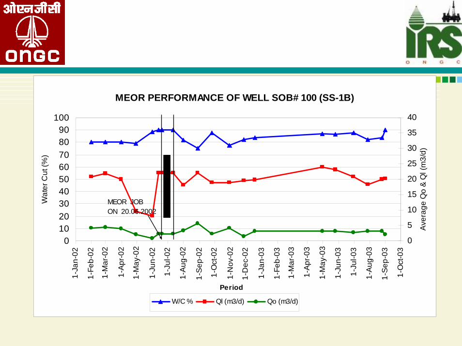
MEOR PERFORMANCE OF WELL SOB# 100 (SS-1B)
0102030405060708090
100
1-Ja
n-02
1-Fe
b-02
1-M
ar-0
2
1-A
pr-0
2
1-M
ay-0
2
1-Ju
n-02
1-Ju
l-02
1-A
ug-0
2
1-S
ep-0
2
1-O
ct-0
2
1-N
ov-0
2
1-D
ec-0
2
1-Ja
n-03
1-Fe
b-03
1-M
ar-0
3
1-A
pr-0
3
1-M
ay-0
3
1-Ju
n-03
1-Ju
l-03
1-A
ug-0
3
1-S
ep-0
3
1-O
ct-0
3
Period
Wat
er C
ut (%
)
0
5
10
15
20
25
30
35
40
Ave
rage
Qo
& Q
l (m
3/d)
W/C % Ql (m3/d) Qo (m3/d)
MEOR JOB ON 20.06.2002

MEOR PERFORMANCE OF WELL NK # 208 (KS- 1A)
0
10
20
30
40
50
60
70
80
90
100
4-O
ct-0
2
11-O
ct-0
2
31-O
ct-0
2
11-N
ov-0
2
18-N
ov-0
2
25-N
ov-0
2
2-D
ec-0
2
9-D
ec-0
2
16-D
ec-0
2
23-D
ec-0
2
30-D
ec-0
2
6-Ja
n-03
13-J
an-0
3
20-J
an-0
3
27-J
an-0
3
4-Fe
b-03
11-F
eb-0
3
18-F
eb-0
3
25-F
eb-0
3
4-M
ar-0
3
11-M
ar-0
3
18-M
ar-0
3
25-M
ar-0
3
31-M
ar-0
3
Period
Wat
er C
ut (%
)
0
5
10
15
20
25
30
35
W/C % QL (m3/d) qo(m3/d)
INCU
BATI
ON
PER
IOD
MEO
R JO
B O
N 1
1.10
.200
2

MEOR JOB PERFORMANCE AT KALOL #104 (XII)
0
10
20
30
40
50
60
70
80
90
100
31-Oct-01
30-Nov-01
31-Dec-01
31-Jan-0228-Feb-0231-M
ar-0230-Apr-0231-M
ay-0230-Jun-0231-Jul-0231-Aug-0230-Sep-0231-O
ct-0230-N
ov-0231-D
ec-0231-Jan-0328-Feb-0331-M
ar-0330-Apr-0331-M
ay-0330-Jun-0331-Jul-0331-Aug-0330-Sep-0331-O
ct-0330-N
ov-0331-D
ec-0331-Jan-0429-Feb-0431-M
ar-0430-Apr-04
Wat
er C
ut %
0
2
4
6
8
10
12
14
16
18
20
W/C % QL M3/day QO,m3/dDATE
Liqu
id ra
te /
Oil r
ate
m3/
d
Mode changed to SRP

PERFORMANCE OF MEOR JOB IN WELL KALOL#72 (XII)
0
10
20
30
40
50
60
70
80
90
100
05.0
6.02
30.0
6.02
17.0
8.02
03.0
9.02
18.1
0.02
25.1
1.02
09.0
2.03
20.0
3.03
14.0
4.03
30.0
6.03
31.1
0.03
31.1
2.03
31.0
1.04
17.0
2.04
10.0
3.04
31.0
3.04
PERIOD
Wat
er C
ut %
0
5
10
15
20
25
30
35
40
W/C% Ql m3/day Qo
Liqu
id r
ate
/ Oil
rate
m3/
d POST MEOR PERFORMANCE
INC
UBA
TIO
N P
ERIO
DR
EPEA
T M
EOR
JO
B O
N 1
1.12
.200
3
PR
E M
EO
R S
TATU
S
INC
UBA
TIO
N P
ERIO
D
MEO
R J
OB
ON
10.
06.2
002
Pow er supply changed to indusrtial feeder on 17.02.04

PERFORMANCE OF MEOR JOB IN KALOL # 56 (IV)
0102030405060708090
100
05.03.02
15.03.02
20.04.02
25.05.02
18.06.02
17.07.02
12.08.02
27.08.02
12.09.02
28.09.02
11.10.02
09.11.02
26.11.02
29.01.03
16.02.03
19.03.03
09.04.03
31.05.03
31.10.03
31.01.04
PERIOD
Wat
er C
ut %
02468101214161820
Liqu
id ra
te, O
il ra
te m
3/d
W/C % Ql- m3/d Qo
MODE OF LIFT CHANGED GL TO SRP ON 05.01.2003
MEOR JOB ON 15.3.2002
POST MEOR STATUS
INCUBATION PERIOD

COST OF MEOR OIL
MEOR job cost with Low temp. consortium :- US $ 3 per barrel (IRS M-1 & IRS M-2)
High temp. consortium :- US 3$ to 6$ per barrel (S-2 consortium)
Pay out period for Low temp. consortium :- 2 monthsHigh temp. consortium :- 3 months

ConclusionsConclusions
Future oil increasingly dependant on IOR/EORStrong cost pressuresApplications of modern technology (multi-
laterals, smart wells)Efficient reservoir management requiredLook for innovative ways continuing
(research)Fiscal incentives & environmental pressures
may steer direction

ConclusionsConclusions
•The forces holding back the oil in the porous rock are the interfacial tension between oil and water, and the viscosity of the crude oil.• EOR has been utilized to overcome or to minimize the physical and geological effects to mobilize additional oil.• It’s usually applied after primary and secondary recovery.• There is no universal method to be applied in any reservoir•Certain reservoir and fluid parameters have to be considered by selecting any EOR methods• Improvement of EOR can be achieved in conjunction with other advanced technologies, such as horizontal drilling etc…