enhanced programmable logic controller gateway parameter ... · enhanced programmable logic...
TRANSCRIPT
Enhanced Programmable Logic Controller Gateway
Parameter Reference DictionaryEP09-440

ImplementationEPLC Gateway
Enhanced ProgrammableLogic Controller Gateway
Parameter Reference DictionaryEP09-440
Release 4309/97
Copyright, Trademarks, and Notices
© Copyright 1992 - 1997 by Honeywell Inc.
Revision 03 – September 20 1997
While this information is presented in good faith and believed to be accurate,Honeywell disclaims the implied warranties of merchantability and fitness for aparticular purpose and makes no express warranties except as may be stated in itswritten agreement with and for its customer.
In no event is Honeywell liable to anyone for any indirect, special or consequentialdamages. The information and specifications in this document are subject tochange without notice.
Honeywell and TDC 3000 are U.S. registered trademarks of Honeywell Inc.
Other brand or product names are trademarks of their respective owners.
EPLCG Parameter Reference Dictionary 9/97
About This PublicationThis is a reference publication for people who need information about the hiway, box/slot,and data point parameters of the Enhanced Programmable Logic Controller Gateway(EPLCG). This publication can be used by engineers, supervisors, and operators becausethe information it contains is useful during the configuration of the EPLCG, and during theoperation of the system.
This publication supports software releases through R430.

EPLCG Parameter Reference Dictionary 9/97
Table of Contents
EPLCG Parameter Reference Dictionary i 9/97
1 INTRODUCTION
1.1 General1.2 Use of This Publication1.3 Notation1.4 Parameter Configuration1.5 References
2 PARAMETER LISTS (PER DATA POINT TYPE)
2.1 General
$-Z PARAMETER DEFINITIONS

EPLCG Parameter Reference Dictionary ii 9/97
EPLCG Parameter Reference Dictionary 1-1 9/97
1
INTRODUCTIONSection 1
1.1 GENERAL
This publication provides reference information about Enhanced Programmable LogicController Gateway (EPLCG) parameters. It also provides listings of parameters that applyto the various EPLCG data point types.
1.2 USE OF THIS PUBLICATION
Use this publication during configuration and during operation when detailed informationabout EPLCG parameters is required.
For use in data point configuration, this publication provides definitions for each entry thatcan be made on the EPLCG Forms in the Implementation/EPLCG binder, and in theParameter Entry Displays at the Universal Station.
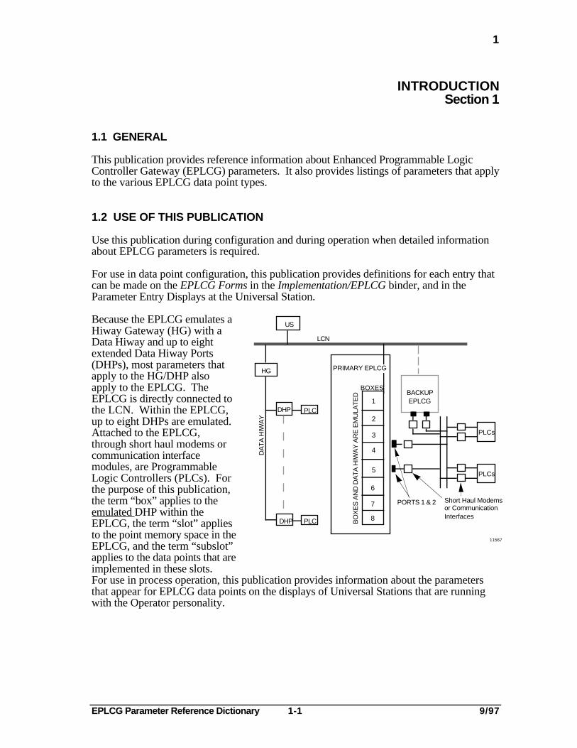
Because the EPLCG emulates aHiway Gateway (HG) with aData Hiway and up to eightextended Data Hiway Ports(DHPs), most parameters thatapply to the HG/DHP alsoapply to the EPLCG. TheEPLCG is directly connected tothe LCN. Within the EPLCG,up to eight DHPs are emulated.Attached to the EPLCG,through short haul modems orcommunication interfacemodules, are ProgrammableLogic Controllers (PLCs). Forthe purpose of this publication,the term “box” applies to theemulated DHP within theEPLCG, the term “slot” appliesto the point memory space in theEPLCG, and the term “subslot”applies to the data points that areimplemented in these slots.
US
HG
DHP PLC
DHP PLC
LCN
1
2
3
4
5
6
7
8
BOXES
BO
XE
S A
ND
DA
TA
HIW
AY
AR
E E
MU
LAT
ED
PORTS 1 & 2
PRIMARY EPLCG
BACKUP EPLCG
DA
TA
HIW
AY
11567
PLCs
PLCs
Short Haul Modemsor Communication Interfaces
For use in process operation, this publication provides information about the parametersthat appear for EPLCG data points on the displays of Universal Stations that are runningwith the Operator personality.
EPLCG Parameter Reference Dictionary 1-2 9/97
1.3
1.3 NOTATION
Parameter names that are listed in this publication are the mnemonics that appear withinparentheses next to the long names of the parameters on the configuration forms, and onthe Universal Station displays. These parameter names consist of up to eight alphabetic oralphanumeric characters. The names are in boldface type with all capital letters such asNAME, OUTSSLT, and so on. When parameter names appear within the definition ofanother parameter, the parameter names are underlined, such as LOADDEST, andINPTSSLT.
No algorithms are associated with the EPLCG.
1.4 PARAMETER CONFIGURATION
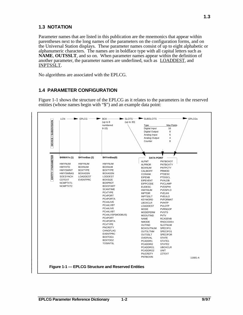
Figure 1-1 shows the structure of the EPLCG as it relates to the parameters in the reservedentities (whose names begin with “$”) and an example data point:
EPLCG
$HYnnBaa (2)
HWYNUMBOXNUMBOXTYPEBOXASSNLOADDESTEVENTPRC
BOX(up to 8numbered8-15)
$HYnnBaa(8)
HWYNUMBOXNUMBOXTYPEBOXASSNLODDESTBOXSIZEBOXPROTBOXSTARTSCANTIMEPCnTYPEPCnPORTPCnPORTAPCnALIVEPCnALVBTPCnALIVEPCnALVBTPCnALVSP(MODBUS)PCnPORTPCnPORTAPCnTYPEPNCRDTYCHNGFLAGEVENTPRCBOXTOG1BOXTOG2TOSINTSL
SLOTS(up to 30)
EPLCGsLCN
$HIWAYn (1)
HWYNUMHWYHTDHWYSWINTHWYSWBASSOESYNCHCDTEXTNCMPTXT1NCMPTXT2
DE
VIC
E /
SU
BD
IVIS
ION
DATA POINT
ALFMTALPRIORBOXNUMCALIBOFFCCRANKEIPENBEIPEVENTEIPPCODEEUDESCHWYNUMINPTDIRINPTSSLTKEYWORDLBOXCLRLOADDESTMODEMODEPERMMOOUTINDNAMENMODEOUTINDBOXOUTNUMOUTSLTNMOUTSSLTOVERVALPCADDR1PCADDRI2PCADDRO1PCADDRO2PIUCRDTYPNTBOXIN
PNTBOXOTPNTBOXTYPNTPCTYPRIMODPTDESCPTDISCLPVALDBPVCLAMPPVDSPHIPVDSPLOPVEUHIPVEULOPVFORMATPVHITPPVLOTPPVRNGOPPVSTSPVTVRCASENBRNGCODEnSLOTNUMSPECIFI1SPECIFO1SPECIFORSTATESTATE1STATE2UBOXCLRUNITZZTEXT
SUBSLOTS
Type Max PointsDigital Input Digital OutputAnalog InputAnalog OutputCounter
168648
11681-A
EN
TITY
/ P
AR
AM
ETE
R
Figure 1-1 — EPLCG Structure and Reserved Entities
EPLCG Parameter Reference Dictionary 1-3 9/97
1.5
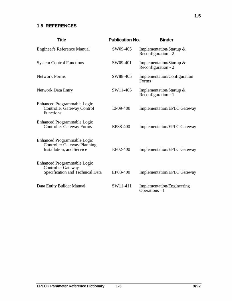
1.5 REFERENCES
Title Publication No. Binder
Engineer's Reference Manual SW09-405 Implementation/Startup &Reconfiguration - 2
System Control Functions SW09-401 Implementation/Startup &Reconfiguration - 2
Network Forms SW88-405 Implementation/ConfigurationForms
Network Data Entry SW11-405 Implementation/Startup &Reconfiguration - 1
Enhanced Programmable LogicController Gateway Control EP09-400 Implementation/EPLC GatewayFunctions
Enhanced Programmable LogicController Gateway Forms EP88-400 Implementation/EPLC Gateway
Enhanced Programmable LogicController Gateway Planning,Installation, and Service EP02-400 Implementation/EPLC Gateway
Enhanced Programmable LogicController GatewaySpecification and Technical Data EP03-400 Implementation/EPLC Gateway
Data Entity Builder Manual SW11-411 Implementation/EngineeringOperations - 1

EPLCG Parameter Reference Dictionary 1-4 9/97
EPLCG Parameter Reference Dictionary 2-1 9/97
2
PARAMETER LISTS (PER DATA POINT TYPE)Section 2
2.1 GENERAL
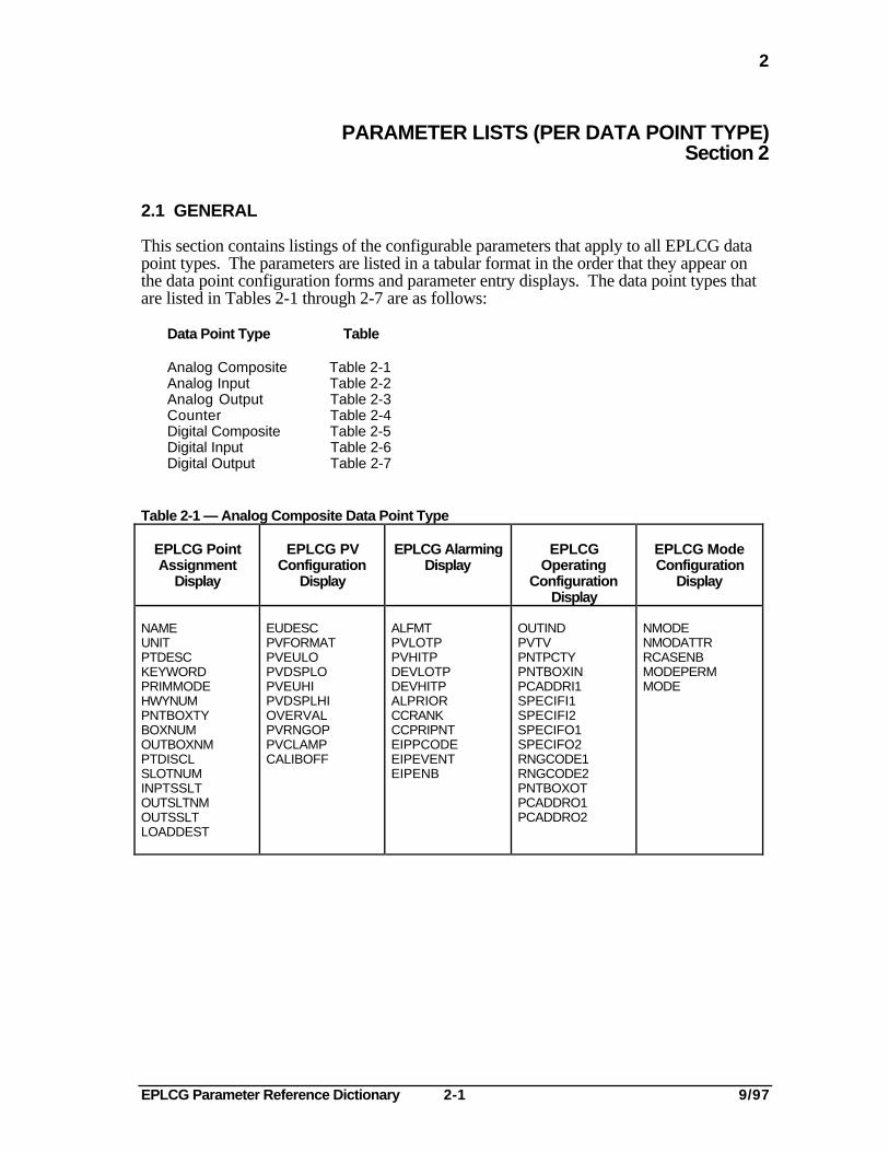
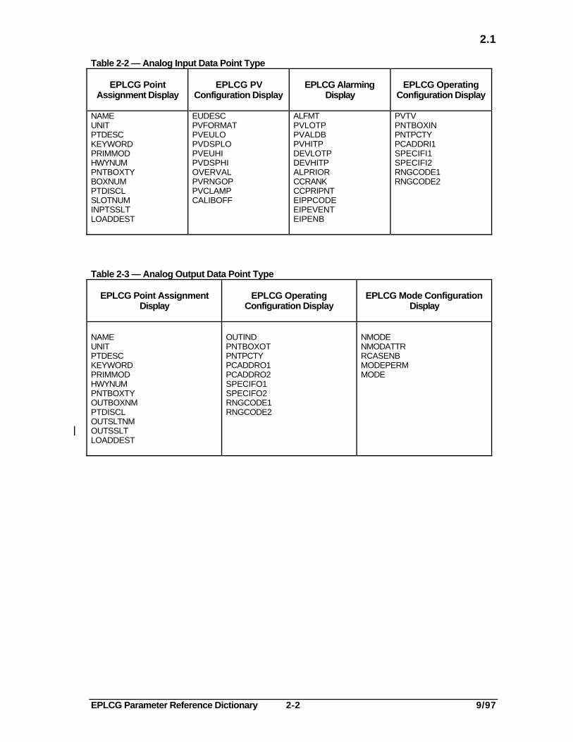
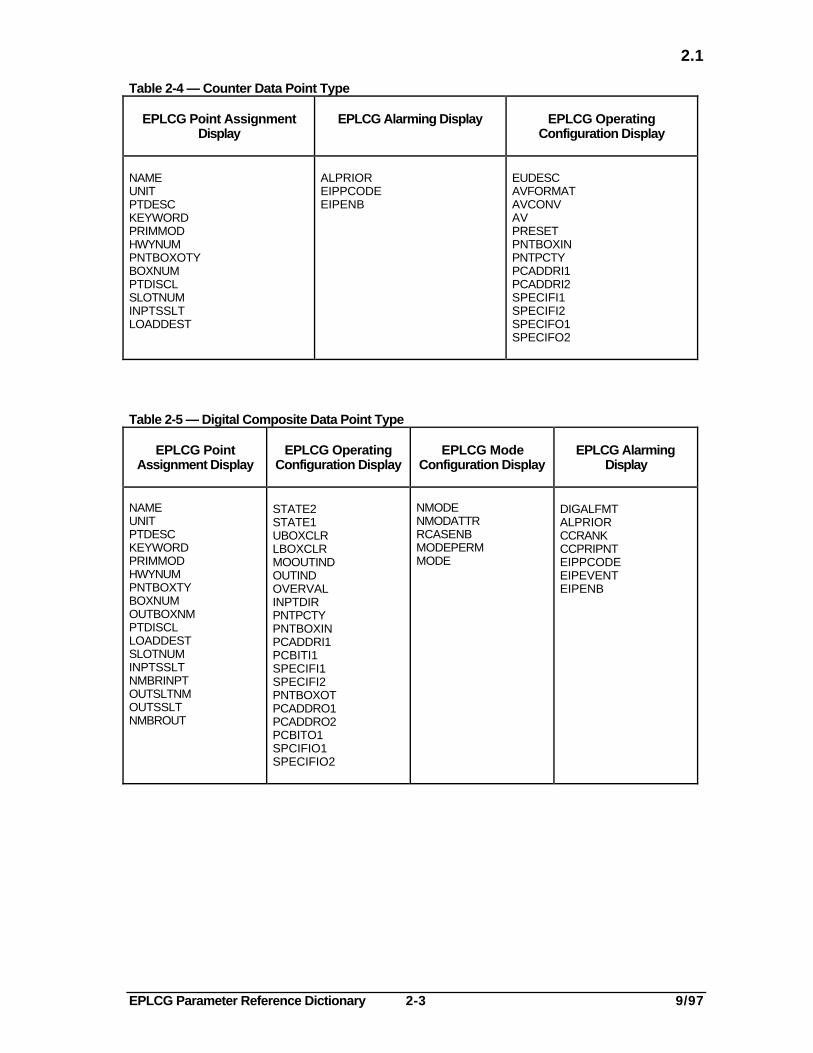
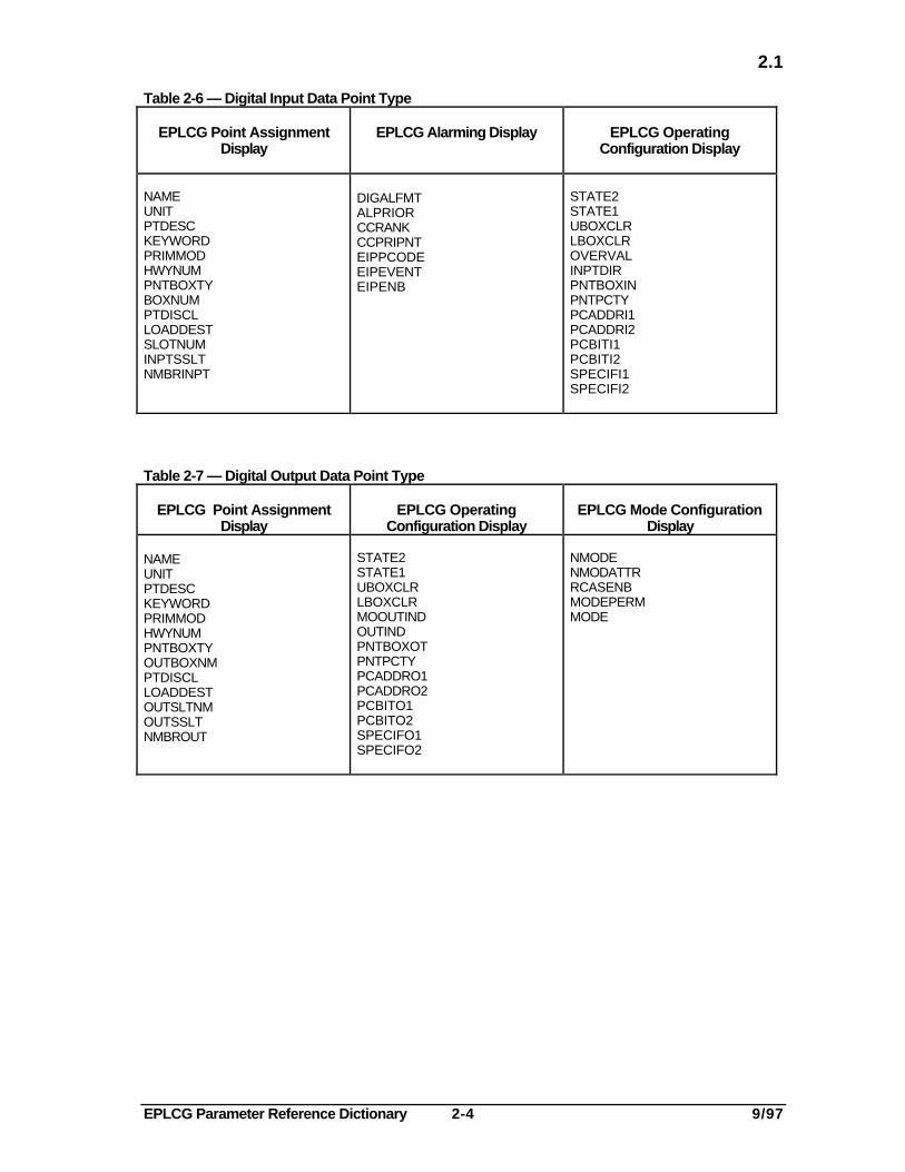
This section contains listings of the configurable parameters that apply to all EPLCG datapoint types. The parameters are listed in a tabular format in the order that they appear onthe data point configuration forms and parameter entry displays. The data point types thatare listed in Tables 2-1 through 2-7 are as follows:
Data Point Type Table
Analog Composite Table 2-1Analog Input Table 2-2Analog Output Table 2-3Counter Table 2-4Digital Composite Table 2-5Digital Input Table 2-6Digital Output Table 2-7
Table 2-1 — Analog Composite Data Point Type
EPLCG PointAssignment
Display
EPLCG PVConfiguration
Display
EPLCG AlarmingDisplay
EPLCGOperating
ConfigurationDisplay
EPLCG ModeConfiguration
Display
NAMEUNITPTDESCKEYWORDPRIMMODEHWYNUMPNTBOXTYBOXNUMOUTBOXNMPTDISCLSLOTNUMINPTSSLTOUTSLTNMOUTSSLTLOADDEST
EUDESCPVFORMATPVEULOPVDSPLOPVEUHIPVDSPLHIOVERVALPVRNGOPPVCLAMPCALIBOFF
ALFMTPVLOTPPVHITPDEVLOTPDEVHITPALPRIORCCRANKCCPRIPNTEIPPCODEEIPEVENTEIPENB
OUTINDPVTVPNTPCTYPNTBOXINPCADDRI1SPECIFI1SPECIFI2SPECIFO1SPECIFO2RNGCODE1RNGCODE2PNTBOXOTPCADDRO1PCADDRO2
NMODENMODATTRRCASENBMODEPERMMODE
EPLCG Parameter Reference Dictionary 2-2 9/97
2.1
Table 2-2 — Analog Input Data Point Type
EPLCG PointAssignment Display
EPLCG PVConfiguration Display
EPLCG AlarmingDisplay
EPLCG OperatingConfiguration Display
NAMEUNITPTDESCKEYWORDPRIMMODHWYNUMPNTBOXTYBOXNUMPTDISCLSLOTNUMINPTSSLTLOADDEST
EUDESCPVFORMATPVEULOPVDSPLOPVEUHIPVDSPHIOVERVALPVRNGOPPVCLAMPCALIBOFF
ALFMTPVLOTPPVALDBPVHITPDEVLOTPDEVHITPALPRIORCCRANKCCPRIPNTEIPPCODEEIPEVENTEIPENB
PVTVPNTBOXINPNTPCTYPCADDRI1SPECIFI1SPECIFI2RNGCODE1RNGCODE2
Table 2-3 — Analog Output Data Point Type
EPLCG Point AssignmentDisplay
EPLCG OperatingConfiguration Display
EPLCG Mode ConfigurationDisplay
NAMEUNITPTDESCKEYWORDPRIMMODHWYNUMPNTBOXTYOUTBOXNMPTDISCLOUTSLTNMOUTSSLTLOADDEST
OUTINDPNTBOXOTPNTPCTYPCADDRO1PCADDRO2SPECIFO1SPECIFO2RNGCODE1RNGCODE2
NMODENMODATTRRCASENBMODEPERMMODE
EPLCG Parameter Reference Dictionary 2-3 9/97
2.1
Table 2-4 — Counter Data Point Type
EPLCG Point AssignmentDisplay
EPLCG Alarming Display EPLCG OperatingConfiguration Display
NAMEUNITPTDESCKEYWORDPRIMMODHWYNUMPNTBOXOTYBOXNUMPTDISCLSLOTNUMINPTSSLTLOADDEST
ALPRIOREIPPCODEEIPENB
EUDESCAVFORMATAVCONVAVPRESETPNTBOXINPNTPCTYPCADDRI1PCADDRI2SPECIFI1SPECIFI2SPECIFO1SPECIFO2
Table 2-5 — Digital Composite Data Point Type
EPLCG PointAssignment Display
EPLCG OperatingConfiguration Display
EPLCG ModeConfiguration Display
EPLCG AlarmingDisplay
NAMEUNITPTDESCKEYWORDPRIMMODHWYNUMPNTBOXTYBOXNUMOUTBOXNMPTDISCLLOADDESTSLOTNUMINPTSSLTNMBRINPTOUTSLTNMOUTSSLTNMBROUT
STATE2STATE1UBOXCLRLBOXCLRMOOUTINDOUTINDOVERVALINPTDIRPNTPCTYPNTBOXINPCADDRI1PCBITI1SPECIFI1SPECIFI2PNTBOXOTPCADDRO1PCADDRO2PCBITO1SPCIFIO1SPECIFIO2
NMODENMODATTRRCASENBMODEPERMMODE
DIGALFMTALPRIORCCRANKCCPRIPNTEIPPCODEEIPEVENTEIPENB
EPLCG Parameter Reference Dictionary 2-4 9/97
2.1
Table 2-6 — Digital Input Data Point Type
EPLCG Point AssignmentDisplay
EPLCG Alarming Display EPLCG OperatingConfiguration Display
NAMEUNITPTDESCKEYWORDPRIMMODHWYNUMPNTBOXTYBOXNUMPTDISCLLOADDESTSLOTNUMINPTSSLTNMBRINPT
DIGALFMTALPRIORCCRANKCCPRIPNTEIPPCODEEIPEVENTEIPENB
STATE2STATE1UBOXCLRLBOXCLROVERVALINPTDIRPNTBOXINPNTPCTYPCADDRI1PCADDRI2PCBITI1PCBITI2SPECIFI1SPECIFI2
Table 2-7 — Digital Output Data Point Type
EPLCG Point AssignmentDisplay
EPLCG OperatingConfiguration Display
EPLCG Mode ConfigurationDisplay
NAMEUNITPTDESCKEYWORDPRIMMODHWYNUMPNTBOXTYOUTBOXNMPTDISCLLOADDESTOUTSLTNMOUTSSLTNMBROUT
STATE2STATE1UBOXCLRLBOXCLRMOOUTINDOUTINDPNTBOXOTPNTPCTYPCADDRO1PCADDRO2PCBITO1PCBITO2SPECIFO1SPECIFO2
NMODENMODATTRRCASENBMODEPERMMODE

EPLCG Parameter Reference Dictionary A-1 9/97
ALFMT
-A-
NOTE
Because the EPLCG emulates an HG with a data hiway and up to eight extended DHPs, mostparameters that apply to the HG/DHP also apply to the EPLCG. Within the EPLCG parameterdefinitions, the terms “box”, “slot”, and “subslot” refer to logical instead of physical devices.
ALFMT—Alarm Format (Analog Data Point)
This parameter defines the type of alarming (PV, deviation, etc.,) that is to be used for ananalog data point. (Enter the alarm trip point values for the selected alarm format on theconfiguration form in the lines that follow the ALFMT line.)
Default AccessSource: User Value: Alfmt00 Lock: Engr.
ValueType: Enum. of Value
ALFMT Range: Alfmt00 = PV alarming (PVLOTP & PVHITP)Alfmt01 = Deviation alarming (DEVLOTP & DEVHITP)
ALPRIOR—Alarm Priority
This parameter defines the priority of an alarm generated by a data point. The alarmpriority determines how the alarm is handled by the system.
Default AccessSource: User Value: Low Lock: Oper. for flag data point
Engr. for all other data points
ValueType: Enum. of
ALPRIOR
Value Noaction = Alarm is not reported to the system. Alarm is not annunciated.Range:
Journal = Alarm is historized but is not reported to the Universal Station. Alarm is not annunciated.
Low = Alarm is historized and is reported to the Universal Station. Alarm is annunciated.
High = Alarm is historized and is reported to the Universal Station. Alarm is annunciated.
Emergncy = This alarm has emergency (first) priority, and is historized and reported to USs(this value not allowed for counter points). The Alarm is annunciated. Each HGhas a capacity of 50 emergency-priority points. Emergency-priority alarms areevaluated by the EPLCG at 1/2 second intervals. Such alarms are reported beforethose for other points when the EPLCG starts up or fails over to the secondaryEPLCG. This priority does not apply to counter points, to digital I/Ocomposite points whose DIGALFMT parameter contains Cmddis, nor to digitalpoints whose PIUCRDOP parameter contains Notifyst.
EPLCG Parameter Reference Dictionary A-2 9/97
AV
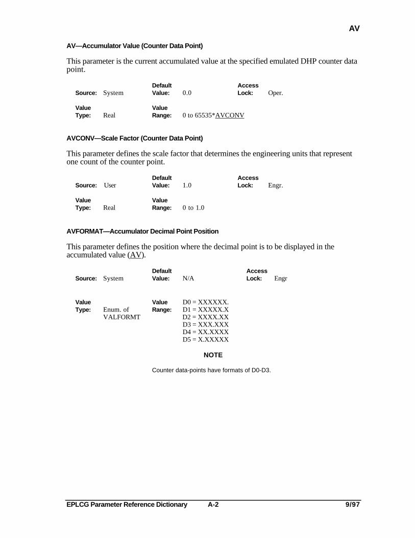
AV—Accumulator Value (Counter Data Point)
This parameter is the current accumulated value at the specified emulated DHP counter datapoint.
Default AccessSource: System Value: 0.0 Lock: Oper.
Value ValueType: Real Range: 0 to 65535*AVCONV
AVCONV—Scale Factor (Counter Data Point)
This parameter defines the scale factor that determines the engineering units that representone count of the counter point.
Default AccessSource: User Value: 1.0 Lock: Engr.
Value ValueType: Real Range: 0 to 1.0
AVFORMAT—Accumulator Decimal Point Position
This parameter defines the position where the decimal point is to be displayed in theaccumulated value (AV).
DefaultSource: System Value: N/A
AccessLock: Engr
Value Value D0 = XXXXXX.Type: Enum. of Range: D1 = XXXXX.X
VALFORMT D2 = XXXX.XXD3 = XXX.XXXD4 = XX.XXXXD5 = X.XXXXX
NOTE
Counter data-points have formats of D0-D3.
EPLCG Parameter Reference Dictionary B-1 9/97
BOXASSN
-B-BOXASSN—Box Assignment
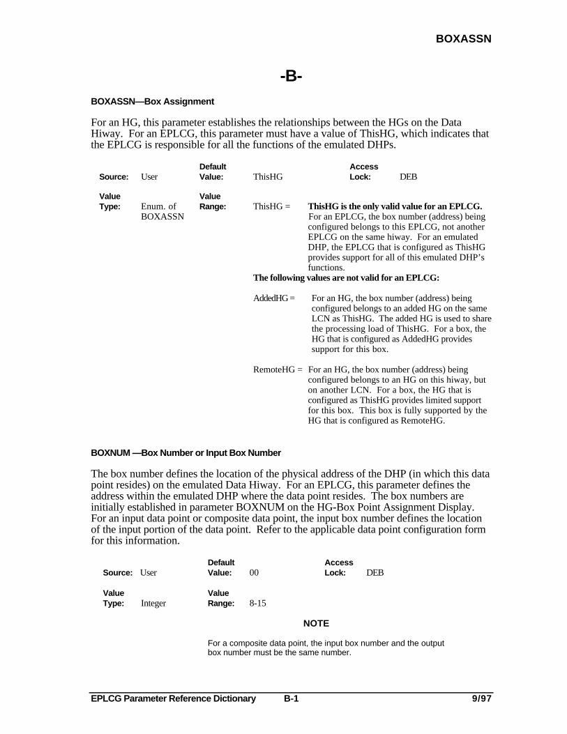
For an HG, this parameter establishes the relationships between the HGs on the DataHiway. For an EPLCG, this parameter must have a value of ThisHG, which indicates thatthe EPLCG is responsible for all the functions of the emulated DHPs.
Default AccessSource: User Value: ThisHG Lock: DEB
Value ValueType: Enum. of Range: ThisHG = ThisHG is the only valid value for an EPLCG.
BOXASSN For an EPLCG, the box number (address) beingconfigured belongs to this EPLCG, not another EPLCG on the same hiway. For an emulated DHP, the EPLCG that is configured as ThisHG provides support for all of this emulated DHP’s functions.
The following values are not valid for an EPLCG:
AddedHG = For an HG, the box number (address) beingconfigured belongs to an added HG on the sameLCN as ThisHG. The added HG is used to sharethe processing load of ThisHG. For a box, theHG that is configured as AddedHG providessupport for this box.
RemoteHG = For an HG, the box number (address) beingconfigured belongs to an HG on this hiway, buton another LCN. For a box, the HG that isconfigured as ThisHG provides limited supportfor this box. This box is fully supported by theHG that is configured as RemoteHG.
BOXNUM —Box Number or Input Box Number
The box number defines the location of the physical address of the DHP (in which this datapoint resides) on the emulated Data Hiway. For an EPLCG, this parameter defines theaddress within the emulated DHP where the data point resides. The box numbers areinitially established in parameter BOXNUM on the HG-Box Point Assignment Display.For an input data point or composite data point, the input box number defines the locationof the input portion of the data point. Refer to the applicable data point configuration formfor this information.
Default AccessSource: User Value: 00 Lock: DEB
Value ValueType: Integer Range: 8-15
NOTE
For a composite data point, the input box number and the outputbox number must be the same number.
EPLCG Parameter Reference Dictionary B-2 9/97
BOXPROT
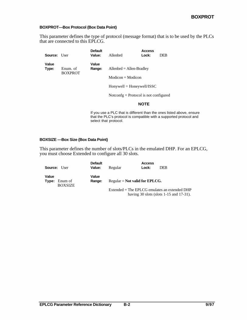
BOXPROT—Box Protocol (Box Data Point)
This parameter defines the type of protocol (message format) that is to be used by the PLCsthat are connected to this EPLCG.
Default AccessSource: User Value: Allenbrd Lock: DEB
Value ValueType: Enum. of Range: Allenbrd = Allen-Bradley
BOXPROTModicon = Modicon
Honywell = Honeywell/ISSC
Notconfg = Protocol is not configured
NOTE
If you use a PLC that is different than the ones listed above, ensurethat the PLC’s protocol is compatible with a supported protocol andselect that protocol.
BOXSIZE —Box Size (Box Data Point)
This parameter defines the number of slots/PLCs in the emulated DHP. For an EPLCG,you must choose Extended to configure all 30 slots.
Default AccessSource: User Value: Regular Lock: DEB
Value ValueType: Enum of Range: Regular = Not valid for EPLCG. BOXSIZE
Extended = The EPLCG emulates an extended DHP having 30 slots (slots 1-15 and 17-31).
EPLCG Parameter Reference Dictionary B-3 9/97
BOXSTAT
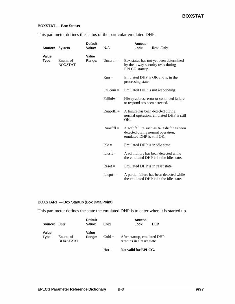
BOXSTAT — Box Status
This parameter defines the status of the particular emulated DHP.
Default AccessSource: System Value: N/A Lock: Read-Only
Value ValueType: Enum. of Range: Uncertn = Box status has not yet been determined
BOXSTAT by the hiway security tests duringEPLCG startup.
Run = Emulated DHP is OK and is in theprocessing state.
Failcom = Emulated DHP is not responding.
Failhdw = Hiway address error or continued failureto respond has been detected.
Runprtfl = A failure has been detected duringnormal operation; emulated DHP is stillOK.
Runsftfl = A soft failure such as A/D drift has beendetected during normal operation;emulated DHP is still OK.
Idle = Emulated DHP is in idle state.
Idlesft = A soft failure has been detected whilethe emulated DHP is in the idle state.
Reset = Emulated DHP is in reset state.
Idleprt = A partial failure has been detected whilethe emulated DHP is in the idle state.
BOXSTART — Box Startup (Box Data Point)
This parameter defines the state the emulated DHP is to enter when it is started up.
Default AccessSource: User Value: Cold Lock: DEB
Value ValueType: Enum. of Range: Cold = After startup, emulated DHP
BOXSTART remains in a reset state.
Hot = Not valid for EPLCG.
EPLCG Parameter Reference Dictionary B-4 9/97
BOXTYPE
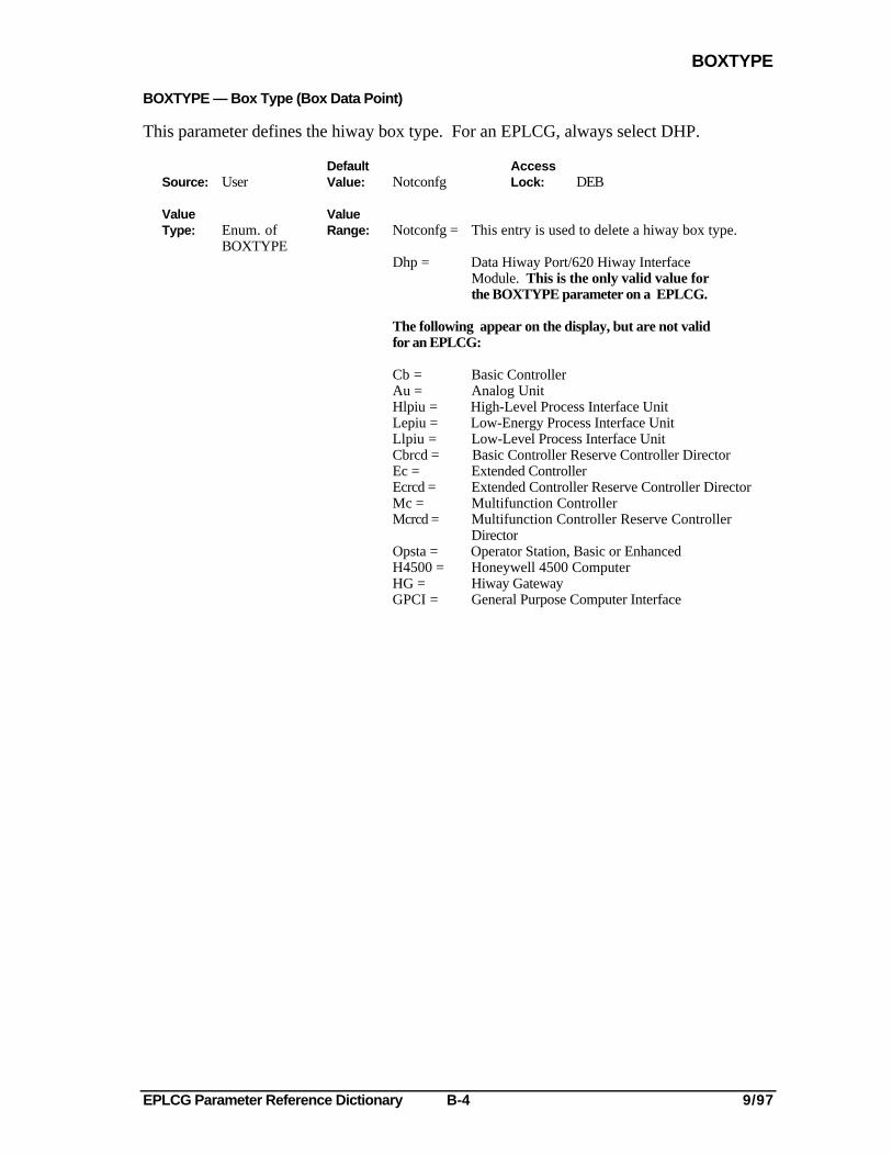
BOXTYPE — Box Type (Box Data Point)
This parameter defines the hiway box type. For an EPLCG, always select DHP.
Default AccessSource: User Value: Notconfg Lock: DEB
Value ValueType: Enum. of Range: Notconfg = This entry is used to delete a hiway box type.
BOXTYPEDhp = Data Hiway Port/620 Hiway Interface
Module. This is the only valid value forthe BOXTYPE parameter on a EPLCG.
The following appear on the display, but are not validfor an EPLCG:
Cb = Basic ControllerAu = Analog UnitHlpiu = High-Level Process Interface UnitLepiu = Low-Energy Process Interface UnitLlpiu = Low-Level Process Interface UnitCbrcd = Basic Controller Reserve Controller DirectorEc = Extended ControllerEcrcd = Extended Controller Reserve Controller DirectorMc = Multifunction ControllerMcrcd = Multifunction Controller Reserve Controller
DirectorOpsta = Operator Station, Basic or EnhancedH4500 = Honeywell 4500 ComputerHG = Hiway GatewayGPCI = General Purpose Computer Interface
EPLCG Parameter Reference Dictionary C-1 9/97
CALIBOFF
-C-
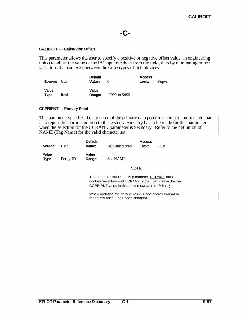
CALIBOFF — Calibration Offset
This parameter allows the user to specify a positive or negative offset value (in engineeringunits) to adjust the value of the PV input received from the field, thereby eliminating minorvariations that can exist between the same types of field devices.
Default AccessSource: User Value: 0 Lock: Supvr.
Value ValueType: Real Range: -9999 to 9999
CCPRIPNT — Primary Point
This parameter specifies the tag name of the primary data point in a contact-cutout chain thatis to report the alarm condition to the system. An entry has to be made for this parameterwhen the selection for the CCRANK parameter is Secndary. Refer to the definition ofNAME (Tag Name) for the valid character set.
Default AccessSource: User Value: All Underscores Lock: DEB
Value Value Type Entity ID Range: See NAME
NOTE
To update the value in this parameter, CCRANK mustcontain Secndary and CCRANK of the point named by theCCPRIPNT value in this point must contain Primary.
When updating the default value, underscores cannot bereentered once it has been changed.
EPLCG Parameter Reference Dictionary C-2 9/97
CCRANK
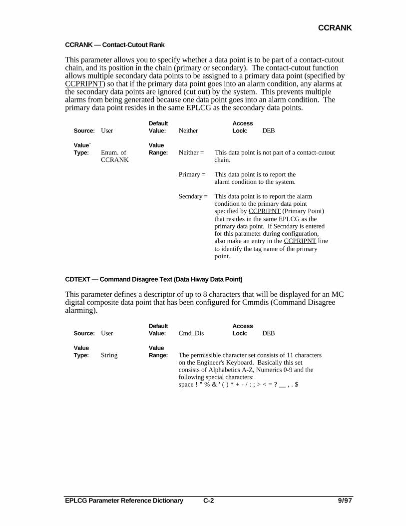
CCRANK — Contact-Cutout Rank
This parameter allows you to specify whether a data point is to be part of a contact-cutoutchain, and its position in the chain (primary or secondary). The contact-cutout functionallows multiple secondary data points to be assigned to a primary data point (specified byCCPRIPNT) so that if the primary data point goes into an alarm condition, any alarms atthe secondary data points are ignored (cut out) by the system. This prevents multiplealarms from being generated because one data point goes into an alarm condition. Theprimary data point resides in the same EPLCG as the secondary data points.
Default AccessSource: User Value: Neither Lock: DEB
Value` ValueType: Enum. of Range: Neither = This data point is not part of a contact-cutout
CCRANK chain.
Primary = This data point is to report thealarm condition to the system.
Secndary = This data point is to report the alarmcondition to the primary data pointspecified by CCPRIPNT (Primary Point)that resides in the same EPLCG as theprimary data point. If Secndary is enteredfor this parameter during configuration,also make an entry in the CCPRIPNT lineto identify the tag name of the primarypoint.
CDTEXT — Command Disagree Text (Data Hiway Data Point)
This parameter defines a descriptor of up to 8 characters that will be displayed for an MCdigital composite data point that has been configured for Cmmdis (Command Disagreealarming).
Default AccessSource: User Value: Cmd_Dis Lock: DEB
Value ValueType: String Range: The permissible character set consists of 11 characters
on the Engineer's Keyboard. Basically this setconsists of Alphabetics A-Z, Numerics 0-9 and thefollowing special characters:space ! " % & ' ( ) * + - / : ; > < = ? __ , . $

EPLCG Parameter Reference Dictionary C-3 9/97
CHOFSTPR
CHOFSTPR—Change of State Alarm Priority
This parameter defines the priority of the Change of State alarm generated by a data point.
Default AccessSource: User Value: Low Lock: Engr.
ValueType: Enum. of
ALPRIOR
ValueRange: NOACTION = Alarm is not reported to the system. Alarm is not annunciated.
JOURNAL = Alarm is historized but is not annunciated. Alarm indicator does appearon Group and Detail displays.
LOW = Alarm is historized, annunciated, and does appear on Group andDetail displays.
HIGH = Alarm is historized, annunciated, and does appear on Group andDetail displays.
EMERGNCY = This alarm has emergency (first) priority, and is historized and reported toUSs (this value not allowed for counter points). The Alarm isannunciated. There is no restriction on capacity.
PRINTER = Alarm is reported to the US RTJ. Alarm is not historized orannunciated, and does appear on Group and Detail displays.
NOTEIf PRINTER is chosen, the alarm is lost if the printer isnot working.
JNLPRINT = Alarm is historized and reported to the US RTJ. Alarm is not annunciatedand does not appear on Group and Detail displays.
EPLCG Parameter Reference Dictionary C-4 9/97
CHPINHWY
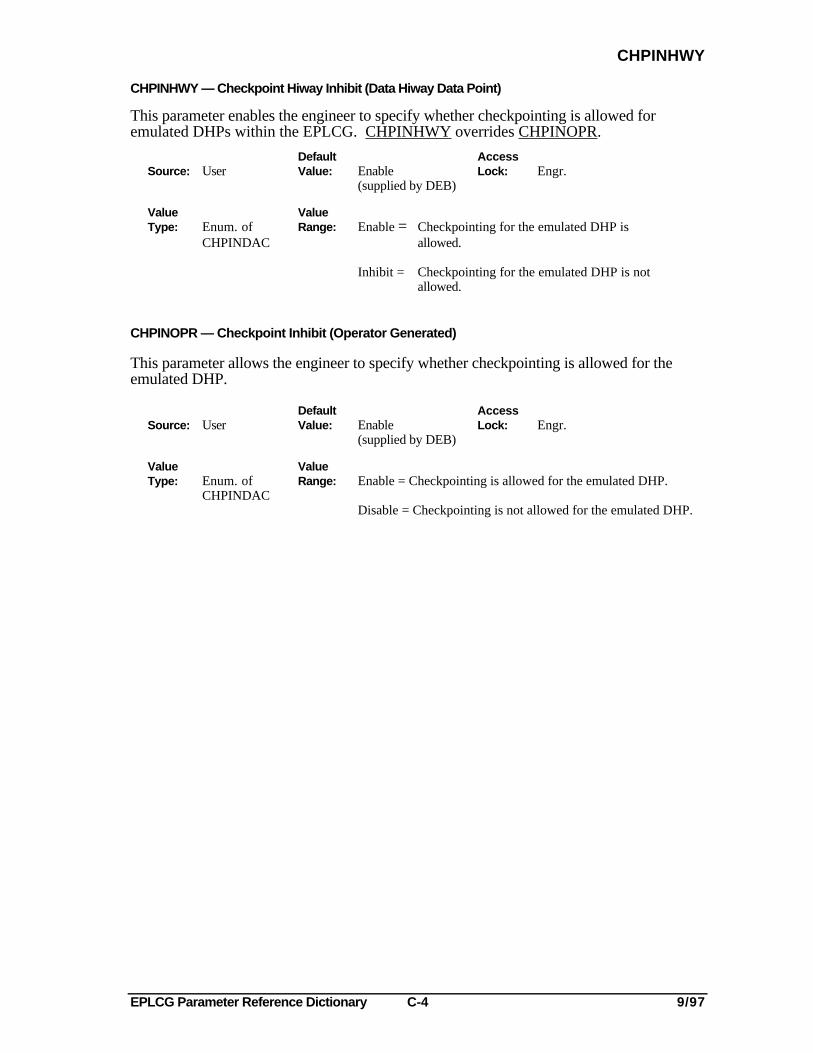
CHPINHWY — Checkpoint Hiway Inhibit (Data Hiway Data Point)
This parameter enables the engineer to specify whether checkpointing is allowed foremulated DHPs within the EPLCG. CHPINHWY overrides CHPINOPR.
Default AccessSource: User Value: Enable Lock: Engr.
(supplied by DEB)
Value ValueType: Enum. of Range: Enable = Checkpointing for the emulated DHP is
CHPINDAC allowed.
Inhibit = Checkpointing for the emulated DHP is notallowed.
CHPINOPR — Checkpoint Inhibit (Operator Generated)
This parameter allows the engineer to specify whether checkpointing is allowed for theemulated DHP.
Default AccessSource: User Value: Enable Lock: Engr.
(supplied by DEB)
Value ValueType: Enum. of Range: Enable = Checkpointing is allowed for the emulated DHP.
CHPINDACDisable = Checkpointing is not allowed for the emulated DHP.
EPLCG Parameter Reference Dictionary C-5 9/97
CMDDISPR
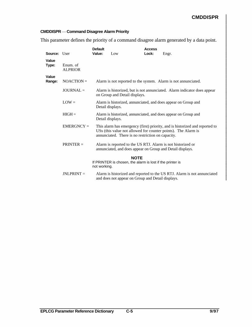
CMDDISPR — Command Disagree Alarm Priority
This parameter defines the priority of a command disagree alarm generated by a data point.
Default AccessSource: User Value: Low Lock: Engr.
ValueType: Enum. of
ALPRIOR
ValueRange: NOACTION = Alarm is not reported to the system. Alarm is not annunciated.
JOURNAL = Alarm is historized, but is not annunciated. Alarm indicator does appearon Group and Detail displays.
LOW = Alarm is historized, annunciated, and does appear on Group andDetail displays.
HIGH = Alarm is historized, annunciated, and does appear on Group andDetail displays.
EMERGNCY = This alarm has emergency (first) priority, and is historized and reported toUSs (this value not allowed for counter points). The Alarm isannunciated. There is no restriction on capacity.
PRINTER = Alarm is reported to the US RTJ. Alarm is not historized orannunciated, and does appear on Group and Detail displays.
NOTEIf PRINTER is chosen, the alarm is lost if the printer isnot working.
JNLPRINT = Alarm is historized and reported to the US RTJ. Alarm is not annunciatedand does not appear on Group and Detail displays.
EPLCG Parameter Reference Dictionary C-6 9/97
COUNTRPR
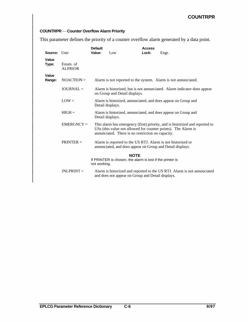
COUNTRPR — Counter Overflow Alarm Priority
This parameter defines the priority of a counter overflow alarm generated by a data point.
Default AccessSource: User Value: Low Lock: Engr.
ValueType: Enum. of
ALPRIOR
ValueRange: NOACTION = Alarm is not reported to the system. Alarm is not annunciated.
JOURNAL = Alarm is historized, but is not annunciated. Alarm indicator does appearon Group and Detail displays.
LOW = Alarm is historized, annunciated, and does appear on Group andDetail displays.
HIGH = Alarm is historized, annunciated, and does appear on Group andDetail displays.
EMERGNCY = This alarm has emergency (first) priority, and is historized and reported toUSs (this value not allowed for counter points). The Alarm isannunciated. There is no restriction on capacity.
PRINTER = Alarm is reported to the US RTJ. Alarm is not historized orannunciated, and does appear on Group and Detail displays.
NOTEIf PRINTER is chosen, the alarm is lost if the printer isnot working.
JNLPRINT = Alarm is historized and reported to the US RTJ. Alarm is not annunciatedand does not appear on Group and Detail displays.
EPLCG Parameter Reference Dictionary C-7 9/97
CNFERRPR
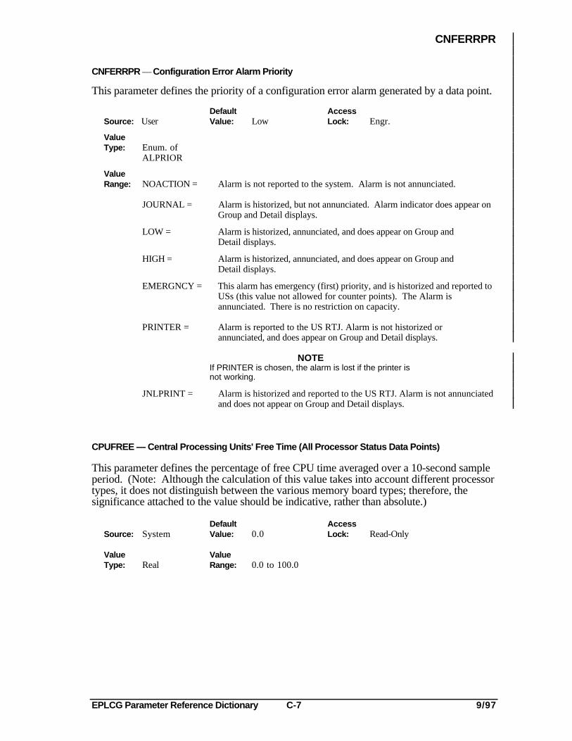
CNFERRPR — Configuration Error Alarm Priority
This parameter defines the priority of a configuration error alarm generated by a data point.
Default AccessSource: User Value: Low Lock: Engr.
ValueType: Enum. of
ALPRIOR
ValueRange: NOACTION = Alarm is not reported to the system. Alarm is not annunciated.
JOURNAL = Alarm is historized, but not annunciated. Alarm indicator does appear onGroup and Detail displays.
LOW = Alarm is historized, annunciated, and does appear on Group andDetail displays.
HIGH = Alarm is historized, annunciated, and does appear on Group andDetail displays.
EMERGNCY = This alarm has emergency (first) priority, and is historized and reported toUSs (this value not allowed for counter points). The Alarm isannunciated. There is no restriction on capacity.
PRINTER = Alarm is reported to the US RTJ. Alarm is not historized orannunciated, and does appear on Group and Detail displays.
NOTEIf PRINTER is chosen, the alarm is lost if the printer isnot working.
JNLPRINT = Alarm is historized and reported to the US RTJ. Alarm is not annunciatedand does not appear on Group and Detail displays.
CPUFREE — Central Processing Units' Free Time (All Processor Status Data Points)
This parameter defines the percentage of free CPU time averaged over a 10-second sampleperiod. (Note: Although the calculation of this value takes into account different processortypes, it does not distinguish between the various memory board types; therefore, thesignificance attached to the value should be indicative, rather than absolute.)
Default AccessSource: System Value: 0.0 Lock: Read-Only
Value ValueType: Real Range: 0.0 to 100.0

EPLCG Parameter Reference Dictionary C-8 9/97
EPLCG Parameter Reference Dictionary D-1 9/97
DEVHIPR
-D-
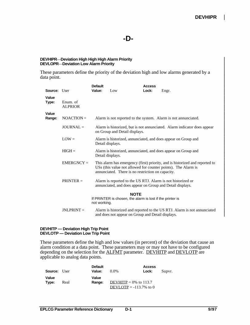
DEVHIPR—Deviation High High High Alarm PriorityDEVLOPR—Deviation Low Alarm Priority
These parameters define the priority of the deviation high and low alarms generated by adata point.
Default AccessSource: User Value: Low Lock: Engr.
ValueType: Enum. of
ALPRIOR
ValueRange: NOACTION = Alarm is not reported to the system. Alarm is not annunciated.
JOURNAL = Alarm is historized, but is not annunciated. Alarm indicator does appearon Group and Detail displays.
LOW = Alarm is historized, annunciated, and does appear on Group andDetail displays.
HIGH = Alarm is historized, annunciated, and does appear on Group andDetail displays.
EMERGNCY = This alarm has emergency (first) priority, and is historized and reported toUSs (this value not allowed for counter points). The Alarm isannunciated. There is no restriction on capacity.
PRINTER = Alarm is reported to the US RTJ. Alarm is not historized orannunciated, and does appear on Group and Detail displays.
NOTEIf PRINTER is chosen, the alarm is lost if the printer isnot working.
JNLPRINT = Alarm is historized and reported to the US RTJ. Alarm is not annunciatedand does not appear on Group and Detail displays.
DEVHITP — Deviation High Trip PointDEVLOTP — Deviation Low Trip Point
These parameters define the high and low values (in percent) of the deviation that cause analarm condition at a data point. These parameters may or may not have to be configureddepending on the selection for the ALFMT parameter. DEVHITP and DEVLOTP areapplicable to analog data points.
Default AccessSource: User Value: 0.0% Lock: Supvr.
Value ValueType: Real Range: DEVHITP = 0% to 113.7
DEVLOTP = -113.7% to 0
EPLCG Parameter Reference Dictionary D-2 9/97
DIGALFMT
DIGALFMT — Alarm Format (Digital Data Points )
This parameter defines the alarm condition that is to be detected at a digital-input data pointor a digital-composite data point.
For additional information about digital states, state text parameters, and state descriptors,refer to 2.3.1 in EPLCG Control Functions in the Implementation/EPLC Gateway binder.
Default AccessSource: User Value: Chngofst Lock: Engr.
Value ValueType: Enum. of Range: The following valid alarm formats are described using
DIGALFMT the upper and lower boxes that appear for a digital datapoint on the Group and Detail Displays. Refer to theconfiguration form to determine which alarm formatsare applicable to the specific digital data point.
EPLCG Parameter Reference Dictionary D-3 9/97
DIGALFMT
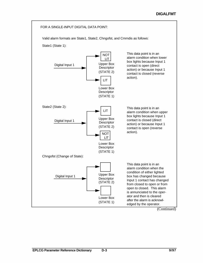
FOR A SINGLE-INPUT DIGITAL DATA POINT:
Digital Input 1DescriptorUpper Box
(STATE 2)
Lower BoxDescriptor(STATE 1)
Digital Input 1
Valid alarm formats are State1, State2, Chngofst, and Cmmdis as follows:
State1 (State 1):
State2 (State 2):
This data point is in analarm condition when lowerbox lights because Input 1contact is open (directaction) or because Input 1contact is closed (reverseaction).
This data point is in analarm condition when upperbox lights because Input 1contact is closed (directaction) or because Input 1contact is open (reverseaction).
Lower Box(STATE 1)
Chngofst (Change of State):
Digital Input 1
This data point is in analarm condition when thecondition of either lightedbox has changed becauseInput 1 contact has changedfrom closed to open or fromopen to closed. This alarmis annunciated to the oper-ator and then is clearedafter the alarm is acknowl-edged by the operator.
Upper Box
(STATE 2)Descriptor
LIT
DescriptorUpper Box
(STATE 2)
Lower BoxDescriptor(STATE 1)
NOT LIT
LIT
NOT LIT
(Continued)
EPLCG Parameter Reference Dictionary D-4 9/97
DIGALFMT
OUTPUT COMMAND "COMMANDED" STATE
DescriptorUpper Box
(STATE 2)
DescriptorLower Box
(STATE 1)
LIT
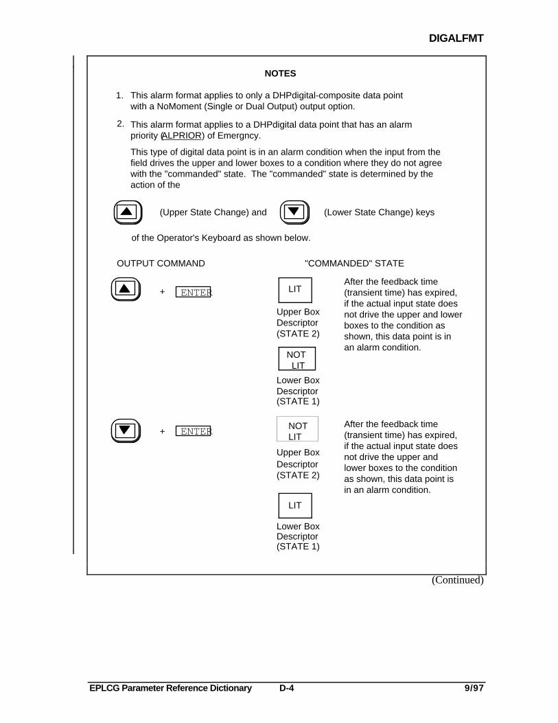
After the feedback time(transient time) has expired,if the actual input state doesnot drive the upper and lowerboxes to the condition asshown, this data point is inan alarm condition.
After the feedback time(transient time) has expired,if the actual input state doesnot drive the upper andlower boxes to the conditionas shown, this data point isin an alarm condition.
Upper BoxDescriptor(STATE 2)
Lower BoxDescriptor(STATE 1)
LIT
NOT LIT
NOTES
1.
2.
This alarm format applies to only a DHPdigital-composite data point with a NoMoment (Single or Dual Output) output option.
This alarm format applies to a DHPdigital data point that has an alarmpriority (ALPRIOR) of Emergncy.
This type of digital data point is in an alarm condition when the input from thefield drives the upper and lower boxes to a condition where they do not agreewith the "commanded" state. The "commanded" state is determined by theaction of the
of the Operator's Keyboard as shown below.
(Upper State Change) and (Lower State Change) keys
ENTER
ENTER
+
+NOTLIT
(Continued)
EPLCG Parameter Reference Dictionary D-5 9/97
DIGALFMT
LIT
NOT LIT
LIT
NOT LIT
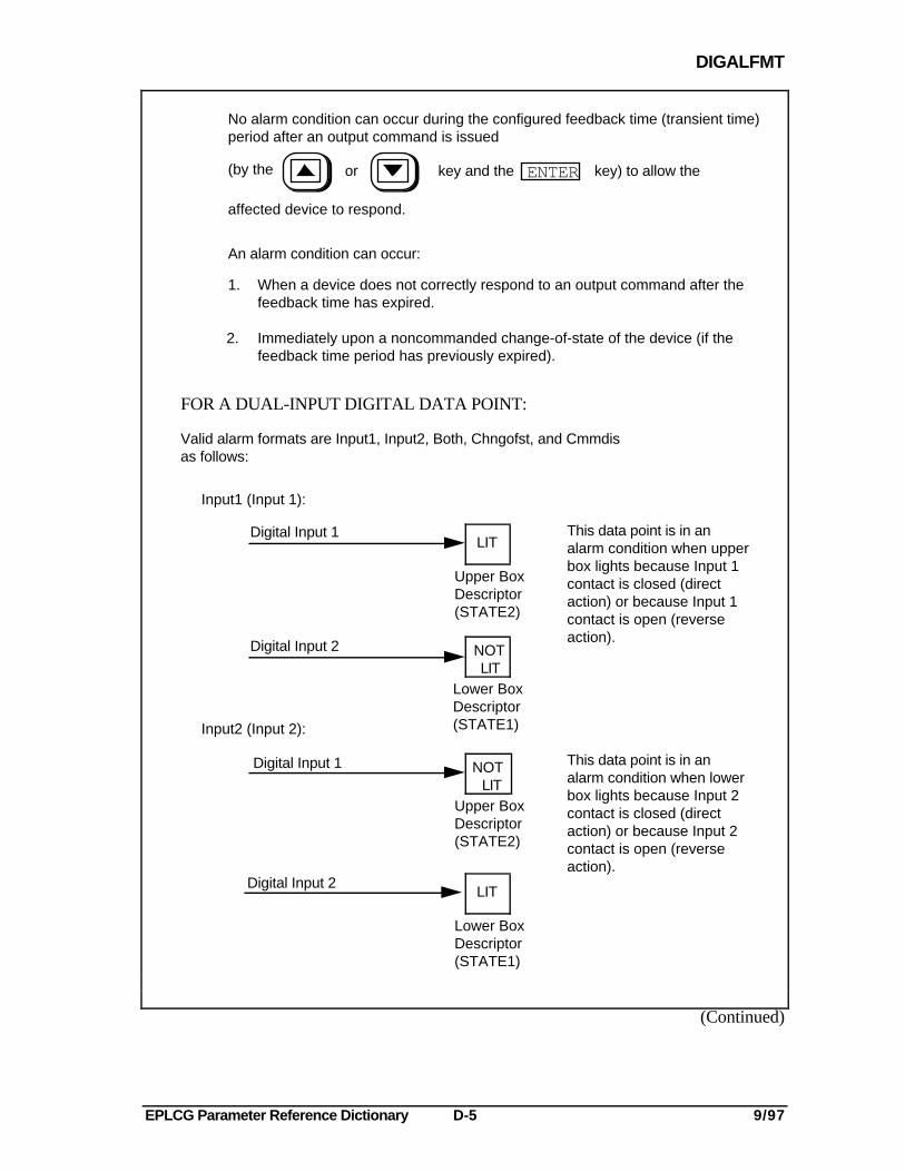
No alarm condition can occur during the configured feedback time (transient time)period after an output command is issued
ENTER(by the or key and the key) to allow the
affected device to respond.
An alarm condition can occur:
1. When a device does not correctly respond to an output command after thefeedback time has expired.
2. Immediately upon a noncommanded change-of-state of the device (if thefeedback time period has previously expired).
Valid alarm formats are Input1, Input2, Both, Chngofst, and Cmmdisas follows:
Input1 (Input 1):
Digital Input 1 This data point is in analarm condition when upperbox lights because Input 1contact is closed (directaction) or because Input 1contact is open (reverseaction).
Digital Input 2
Input2 (Input 2):
Digital Input 1
Digital Input 2
This data point is in analarm condition when lowerbox lights because Input 2contact is closed (directaction) or because Input 2contact is open (reverseaction).
Upper BoxDescriptor(STATE2)
Lower BoxDescriptor(STATE1)
Upper BoxDescriptor(STATE2)
Lower BoxDescriptor(STATE1)
FOR A DUAL-INPUT DIGITAL DATA POINT:
(Continued)

EPLCG Parameter Reference Dictionary D-6 9/97
DIGALFMT
Digital Input 1
Digital Input 2
Lower BoxDescriptor(STATE1)
Upper BoxDescriptor(STATE2)
LIT
Both (Both):
Digital Input 1
Digital Input 2
Upper BoxDescriptor(STATE2)
Lower BoxDescriptor(STATE1)
Chngofst (Change of State):
Digital Input 1
Digital Input 2
Upper BoxDescriptor(STATE2)
Lower BoxDescriptor(STATE1)
This data point is in analarm condition when eitherthe upper or lower boxlights because the respec-tive Input 1 or Input 2contact is closed (directaction) or open (reverseaction).
This data point is in analarm condition when boththe upper and lower boxesare lighted because bothInput 1 and Input 2 contactsare closed (direct action)or are open (reverseaction).
This data point is in analarm condition when thecondition of either lightedbox has changed because theInput 1 or Input 2 contacthas changed from closed toopen or from open to closed.This condition is annunci-ated to the operator and isacknowledged by theoperator.
LIT
Cmmdis (Command Disagree):
NOTES
1. This alarm format applies to only DHP digital composite data points with a NoMoment (Single or Dual Output) output options.
(Continued)
EPLCG Parameter Reference Dictionary D-7 9/97
DIGALFMT
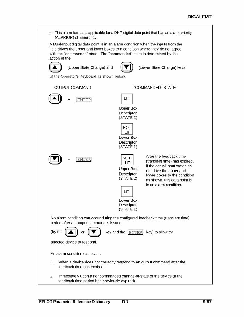
OUTPUT COMMAND "COMMANDED" STATE
After the feedback time(transient time) has expired,if the actual input states donot drive the upper andlower boxes to the conditionas shown, this data point isin an alarm condition.
DescriptorUpper Box
(STATE 2)
DescriptorLower Box
(STATE 1)
LIT
NOT LIT
Upper BoxDescriptor(STATE 2)
Lower BoxDescriptor(STATE 1)
LIT
NOT LIT
ENTER
ENTER
+
+
No alarm condition can occur during the configured feedback time (transient time)period after an output command is issued
ENTER(by the or key and the key) to allow the
affected device to respond.
An alarm condition can occur:
1. When a device does not correctly respond to an output command after thefeedback time has expired.
2. Immediately upon a noncommanded change-of-state of the device (if thefeedback time period has previously expired).
(Upper State Change) and (Lower State Change) keys
2.
A Dual-Input digital data point is in an alarm condition when the inputs from thefield drives the upper and lower boxes to a condition where they do not agreewith the "commanded" state. The "commanded" state is determined by theaction of the
of the Operator's Keyboard as shown below.
This alarm format is applicable for a DHP digital data point that has an alarm priority (ALPRIOR) of Emergncy.
EPLCG Parameter Reference Dictionary D-8 9/97
DIGTEXT
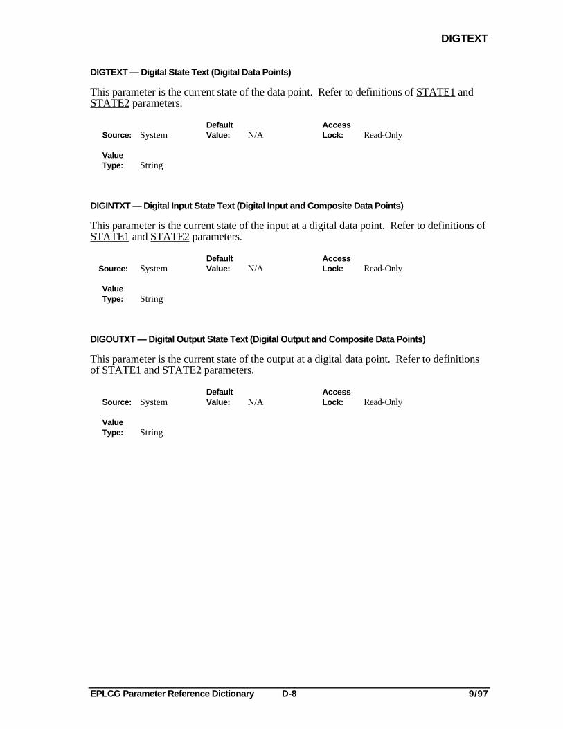
DIGTEXT — Digital State Text (Digital Data Points)
This parameter is the current state of the data point. Refer to definitions of STATE1 andSTATE2 parameters.
Default AccessSource: System Value: N/A Lock: Read-Only
ValueType: String
DIGINTXT — Digital Input State Text (Digital Input and Composite Data Points)
This parameter is the current state of the input at a digital data point. Refer to definitions ofSTATE1 and STATE2 parameters.
Default AccessSource: System Value: N/A Lock: Read-Only
ValueType: String
DIGOUTXT — Digital Output State Text (Digital Output and Composite Data Points)
This parameter is the current state of the output at a digital data point. Refer to definitionsof STATE1 and STATE2 parameters.
Default AccessSource: System Value: N/A Lock: Read-Only
ValueType: String
EPLCG Parameter Reference Dictionary E-1 9/97
EIPENB
-E-
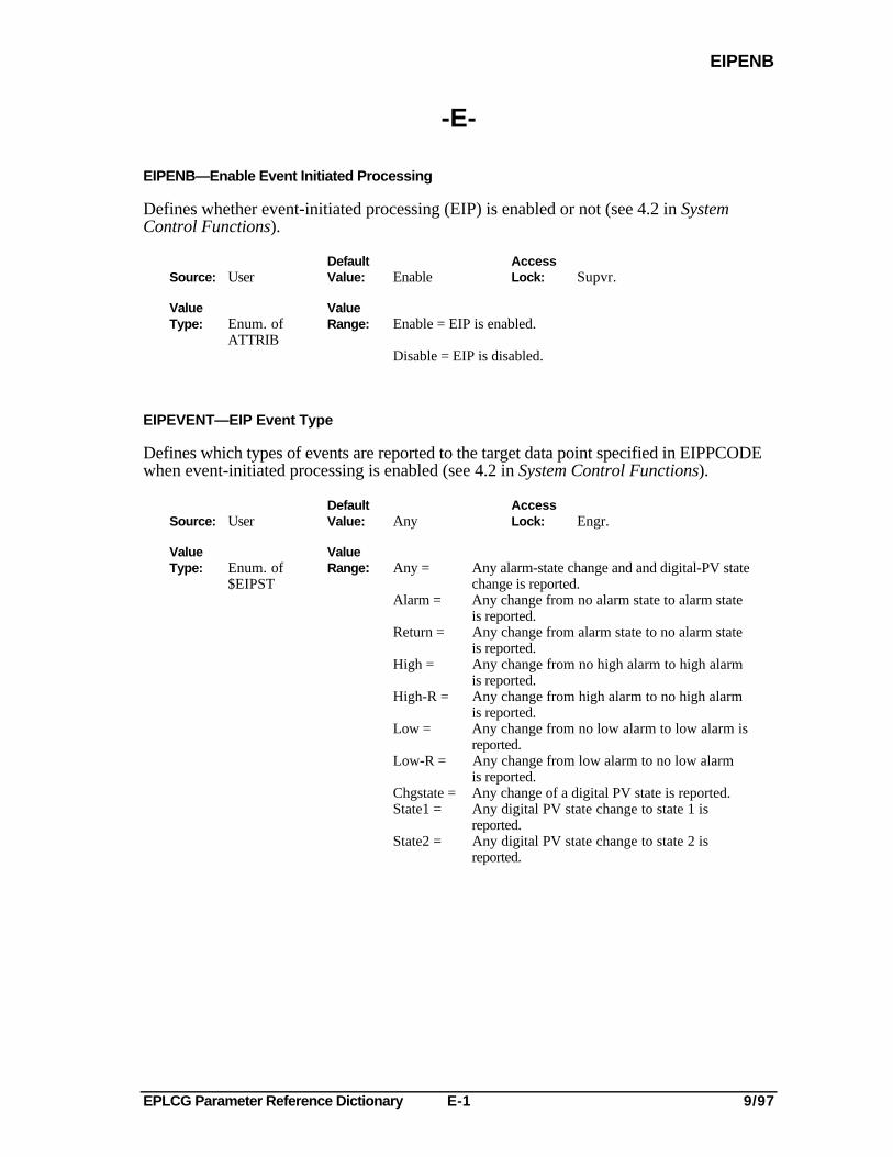
EIPENB—Enable Event Initiated Processing
Defines whether event-initiated processing (EIP) is enabled or not (see 4.2 in SystemControl Functions).
Default AccessSource: User Value: Enable Lock: Supvr.
Value ValueType: Enum. of Range: Enable = EIP is enabled.
ATTRIBDisable = EIP is disabled.
EIPEVENT—EIP Event Type
Defines which types of events are reported to the target data point specified in EIPPCODEwhen event-initiated processing is enabled (see 4.2 in System Control Functions).
Default AccessSource: User Value: Any Lock: Engr.
Value ValueType: Enum. of Range: Any = Any alarm-state change and and digital-PV state
$EIPST change is reported.Alarm = Any change from no alarm state to alarm state
is reported.Return = Any change from alarm state to no alarm state
is reported.High = Any change from no high alarm to high alarm
is reported.High-R = Any change from high alarm to no high alarm
is reported.Low = Any change from no low alarm to low alarm is
reported.Low-R = Any change from low alarm to no low alarm
is reported.Chgstate = Any change of a digital PV state is reported.State1 = Any digital PV state change to state 1 is
reported.State2 = Any digital PV state change to state 2 is
reported.
EPLCG Parameter Reference Dictionary E-2 9/97
EIPPCODE
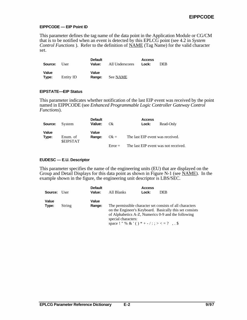
EIPPCODE — EIP Point ID
This parameter defines the tag name of the data point in the Application Module or CG/CMthat is to be notified when an event is detected by this EPLCG point (see 4.2 in SystemControl Functions ). Refer to the definition of NAME (Tag Name) for the valid characterset.
Default AccessSource: User Value: All Underscores Lock: DEB
Value ValueType: Entity ID Range: See NAME
EIPSTATE—EIP Status
This parameter indicates whether notification of the last EIP event was received by the pointnamed in EIPPCODE (see Enhanced Programmable Logic Controller Gateway ControlFunctions).
Default AccessSource: System Value: Ok Lock: Read-Only
Value ValueType: Enum. of Range: Ok = The last EIP event was received.
$EIPSTATError = The last EIP event was not received.
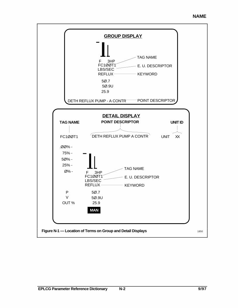
EUDESC — E.U. Descriptor
This parameter specifies the name of the engineering units (EU) that are displayed on theGroup and Detail Displays for this data point as shown in Figure N-1 (see NAME). In theexample shown in the figure, the engineering unit descriptor is LBS/SEC.
Default AccessSource: User Value: All Blanks Lock: DEB
Value ValueType: String Range: The permissible character set consists of all characters
on the Engineer's Keyboard. Basically this set consistsof Alphabetics A-Z, Numerics 0-9 and the following special characters:space ! " % & ' ( ) * + - / : ; > < = ? , . $

EPLCG Parameter Reference Dictionary E-3 9/97
EVENTPRC
EVENTPRC — Event Processing (Box Data Points)
This parameter defines whether process events (process alarms, process changes, andoperator messages) that pertain to the emulated DHP are to be routed through the EPLCGto the LCN.
Default AccessSource: User Value: Enable Lock: Engr.
Value ValueType: Enum. of Range: Disable = Process events for the emulated DHP are
ENBLSTAT not to be routed through the EPLCG to the LCN.
Enable = Process events for the emulated DHP are to be routed through the EPLCG to the LCN.
EVTRATE— # of Detected Process Changes (EPLCG Processor Status Data Points)
This parameter defines the number of detected process changes during the last 15-secondsample period.
Default AccessSource: System Value: 0.0 Lock: Read-Only
Value ValueType: Real Range: ≥ 0.0

EPLCG Parameter Reference Dictionary E-4 9/97
EPLCG Parameter Reference Dictionary F-1 9/97
FBTIME
-F-
FBTIME — Feedback Time (HLPIU and MC Digital Composite Data Points)
This parameter defines the duration (in seconds) for which alarming is suppressedfollowing an output command from a digital-composite data point that has been configuredfor command-disagree alarming.
Default AccessSource: User Value: 0 Lock: Supervisor
Value ValueType: Integer Range: 0 to 1023

EPLCG Parameter Reference Dictionary F-2 9/97
EPLCG Parameter Reference Dictionary H-1 9/97
HIWAYWRD
-H-
HIWAYWRD — Diagnostic Hiway Addressing
This parameter is a diagnostic tool that allows the accessing of memory locations within anemulated DHP during testing.
Default AccessSource: System Value: N/A Lock: Read-Only
ValueType: Integer
HWYACT — Active Hiway Indicator
In the HG, this parameter indicates which emulated hiway (A or B) is presently being usedfor transmitting information. In the EPLCG, the Data Hiway is emulated, and there are nophysical cables. However, the cable indication remains on the display, and indicates cableA until the operator changes it, or until the system changes it during a software failure.
Default AccessSource: System Value: N/A Lock: Read-Only
Value ValueType: Enum. of Range: Nonact = Neither EPLCG cable is active.
HWYACTActa = EPLCG cable A is active.
Actb = EPLCG cable B is active.
HWYASWST — Hiway Automatic Swap Option
This parameter exists in the EPLCG, but has no meaning, because the data hiway isemulated. In the HG, the parameter defines whether automatic switching of the hiwaycables is to occur (only when the HG is designated as the HTD). If automatic switching isselected, it will occur at the time of day specified by the HWYSWBAS (Switch Base Time)parameter.
EPLCG Parameter Reference Dictionary H-2 9/97
HWYCTLST
HWYCTLST — Hiway Control State
This parameter defines the functional state of a Data Hiway.
Default Basic AccessSource: System Value: (supplied by DEB) Lock: Supvr.
Value ValueType: Enum. of Range: Read = AM can read data from the boxes, but cannot
BOXFSTAT write data into the boxes on this hiway.
Full = AM can read data from and write data into theboxes on this hiway.
Basic = AM can read data from the boxes, but cannotwrite data into the boxes on this hiway.
Test = A box is being tested.
NOTES
The Hiway Control State supersedes the Box Functional State. Forexample, if the HWYCTLST = BASIC and the BOXFSTAT = FULLthen the BOXFSTAT = BASIC until the HWYCTLST = FULL.
If an AM is to write to an emulated DHP in an EPLCG, HWYCTLSTand BOXFSTAT must be FULL.
HWYDEVEN — Hiway Preferred Device Option
This parameter exists in the EPLCG, but has no meaning. In the HG, it indicates whichdevices are active preferred devices.
EPLCG Parameter Reference Dictionary H-3 9/97
HWYERR(N)
HWYERR (N) — # of Errors for Box N at each Hiway (EPLCG Processor Status Data Points)
This parameter defines the number of errors for emulated DHP (box) on each EPLCGduring the last 15-second sample period.
Default AccessSource: System Value: 0.0 Lock: Read Only
Value ValueType: ARRAY [1..63] Range: ≥ 0.0
of REAL
HWYHSAST — Hiway Swap Algorithm State
This parameter exists in the EPLCG, but has no meaning. In the HG, it indicates the stateof the hiway swap algorithm.
HWYHTD — HTD Assignment (Box Data Point)
This parameter specifies the device that performs the function of a Hiway Traffic Director(HTD).
Default AccessSource: User Value: Htd Lock: DEB
Value ValueRange: Enum. of Type: ThisHG = The EPLCG assigned to this hiway
HWYHTD acts as the HTD on this physical hiway. This is the only valid value for a EPLCG.
The following values are not valid for a EPLCG:
RemoteHG =The HG on another LCN acts as the HTDon this physical hiway.
AddedHG = The HG on this LCN, but assigned to adifferent hiway number acts as the HTD.
Htd = Physical HTD is in use.
NOTE
Because ThisHG is the only valid value for HWYHTD, ensure thatyou complete the entries for the HWYSWINT (Switch Interval) andHWYSWBAS (Switch Base Time) parameters on the Data HiwayData Point Configuration Form.
EPLCG Parameter Reference Dictionary H-4 9/97
HWYNUM
HWYNUM — Hiway Number
The hiway number defines the hiway (process network) for the emulated Data Hiway. Forthe EPLCG, this parameter assigns a logical hiway number to the EPLCG that identifiesthis EPLCG and its emulated Data Hiway.
Default AccessSource: User Value: 01 Lock: DEB
Value ValueType: Integer Range: 01 to 20
HWYREDST — Hiway Redundancy State
This parameter indicates whether this EPLCG is redundant, and if so, if this is the primaryEPLCG or the secondary EPLCG.
Default AccessSource: System Value: Primary Lock: Read-Only
Value ValueType: Enum. of Range: Inactive = EPLCG redundancy state is presently inactive
(transient state that occurs during the upgrade procedure).
HWYREDSTPrimary = EPLCG is the primary EPLCG. (Also, the state
returned for a nonredundant EPLCG.)
Secndry = EPLCG is the redundant EPLCG.
HWYSTAT — Hiway Status
This parameter indicates the current status of the emulated Data Hiway.
Default AccessSource: System Value: N/A Lock: Read-Only
Value ValueType: Enum. of Range: Uncertn = A Hiway has not finished startup or there is no
HWYSTAT emulated DHP configured on the Hiway.
Init = Hiway is being initialized.
Run = Hiway is operating properly.
Failed = Hiway cannot communicate with any of the emulated DHPs.
EPLCG Parameter Reference Dictionary H-5 9/97
HWYSWBAS
HWYSWBAS — Switch Base Time (EPLCG Data Point)
This parameter defines the time of day (in minutes) during which Hiway switching is totake place.
Default AccessSource: User Value: 0 (12:00 AM midnight) Lock: DEB
Value ValueType: Integer Range: 0 to 1440 minutes
Example: 1:30 AM would be entered as 90Example: 3:00 PM would be entered as 900
NOTE
Because HWYHTD=ThisHG must be specified for a EPLCG, youmust ensure that an entry is to be made for this parameter. Werecommend that you enter the value of 0.
HWYSWINT — Switch Interval (Min) (EPLCG Data Point)
This parameter defines the amount of time (in minutes) between automatic switching of theemulated primary and backup data hiways.
Default AccessSource: User Value: 1440 minutes Lock: DEB
Value ValueType: Integer Range: 0 to 1440 minutes (1440 is the number of minutes in
one day).
NOTE
Because HWYHTD=ThisHG must be specified for a EPLCG, youmust ensure that an entry is to be made for this parameter. Werecommend that you enter the value of 1440.
HWYSWST — Hiway Swap State
This parameter exists in the EPLCG, but has no meaning. In the HG, it indicates if theemulated hiway cables have yet to be swapped (based on the hiway swap algorithm).

EPLCG Parameter Reference Dictionary H-6 9/97
EPLCG Parameter Reference Dictionary I-1 9/97
INPTCOND
-I-
INPTCOND — Input Conditioning
This parameter defines the type of input conditioning required for the PV input of analogdata points.
Default AccessSource: User Value: Linear Lock: Engr.
Value ValueType: Enum. of Range: Linear = Linear Conditioning
INPTCOND
NOTE
To update the value in this parameter, MODE must contain Man.
EPLCG Parameter Reference Dictionary I-2 9/97
INPTDIR
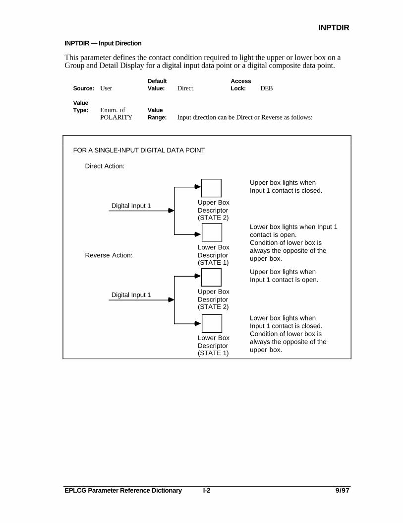
INPTDIR — Input Direction
This parameter defines the contact condition required to light the upper or lower box on aGroup and Detail Display for a digital input data point or a digital composite data point.
Default AccessSource: User Value: Direct Lock: DEB
ValueType: Enum. of Value
POLARITY Range: Input direction can be Direct or Reverse as follows:
Direct Action:
Digital Input 1
Upper box lights whenInput 1 contact is closed.
Upper Box
(STATE 2)Descriptor
Reverse Action:
Digital Input 1 Upper Box
(STATE 2)Descriptor
FOR A SINGLE-INPUT DIGITAL DATA POINT
Lower Box
(STATE 1)Descriptor
Lower Box
(STATE 1)Descriptor
Lower box lights when Input 1contact is open.Condition of lower box isalways the opposite of theupper box.
Upper box lights whenInput 1 contact is open.
Lower box lights whenInput 1 contact is closed.Condition of lower box isalways the opposite of theupper box.
EPLCG Parameter Reference Dictionary I-3 9/97
INPTSSLT
Upper box lights whenInput 1 contact is closed.
Direct Action:
Digital Input 1
Digital Input 2
Reverse Action:
Digital Input 1
Digital Input 2
Upper BoxDescriptor(STATE2)
Lower BoxDescriptor(STATE1)
Upper BoxDescriptor(STATE2)
Lower BoxDescriptor(STATE1)
FOR A DUAL-INPUT DIGITAL DATA POINT:
Lower box lights whenInput 2 contact is closed.
Upper box lights whenInput 1 contact is open.
Lower box lights whenInput 2 contact is open.
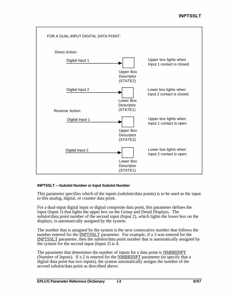
INPTSSLT —Subslot Number or Input Subslot Number
This parameter specifies which of the inputs (subslots/data points) is to be used as the inputto this analog, digital, or counter data point.
For a dual-input digital input or digital composite data point, this parameter defines theinput (Input 1) that lights the upper box on the Group and Detail Displays. Thesubslot/data point number of the second input (Input 2), which lights the lower box on thedisplays, is automatically assigned by the system.
The number that is assigned by the system is the next consecutive number that follows thenumber entered for the INPTSSLT parameter. For example, if a 3 was entered for theINPTSSLT parameter, then the subslot/data point number that is automatically assigned bythe system for the second input (Input 2) is 4.
The parameter that determines the number of inputs for a data point is NMBRINPT(Number of Inputs). If a 2 is entered for the NMBRINPT parameter (to specify that adigital data point has two inputs), the system automatically assigns the number of thesecond subslot/data point as described above.
EPLCG Parameter Reference Dictionary I-4 9/97
IOCBS
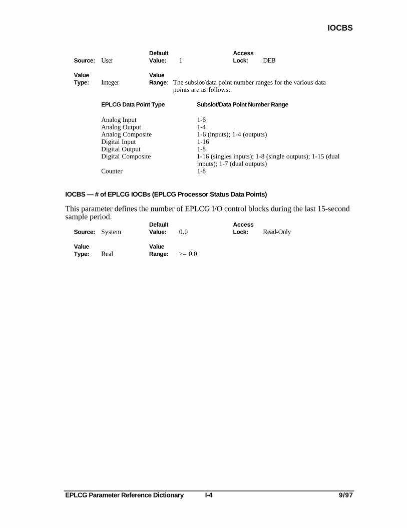
Default AccessSource: User Value: 1 Lock: DEB
Value ValueType: Integer Range: The subslot/data point number ranges for the various data
points are as follows:
EPLCG Data Point Type Subslot/Data Point Number Range
Analog Input 1-6Analog Output 1-4Analog Composite 1-6 (inputs); 1-4 (outputs)Digital Input 1-16Digital Output 1-8Digital Composite 1-16 (singles inputs); 1-8 (single outputs); 1-15 (dual
inputs); 1-7 (dual outputs)Counter 1-8
IOCBS — # of EPLCG IOCBs (EPLCG Processor Status Data Points)
This parameter defines the number of EPLCG I/O control blocks during the last 15-secondsample period.
Default AccessSource: System Value: 0.0 Lock: Read-Only
Value ValueType: Real Range: >= 0.0
EPLCG Parameter Reference Dictionary K-1 9/97
KEYWORD
-K-
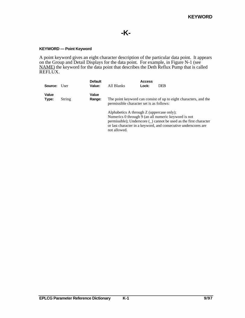
KEYWORD — Point Keyword
A point keyword gives an eight character description of the particular data point. It appearson the Group and Detail Displays for the data point. For example, in Figure N-1 (seeNAME) the keyword for the data point that describes the Deth Reflux Pump that is calledREFLUX.
Default AccessSource: User Value: All Blanks Lock: DEB
Value ValueType: String Range: The point keyword can consist of up to eight characters, and the
permissible character set is as follows:
Alphabetics A through Z (uppercase only);Numerics 0 through 9 (an all numeric keyword is notpermissible); Underscore (_) cannot be used as the first characteror last character in a keyword, and consecutive underscores arenot allowed.

EPLCG Parameter Reference Dictionary K-2 9/97
EPLCG Parameter Reference Dictionary L-1 9/97
LBOXCLR
-L-
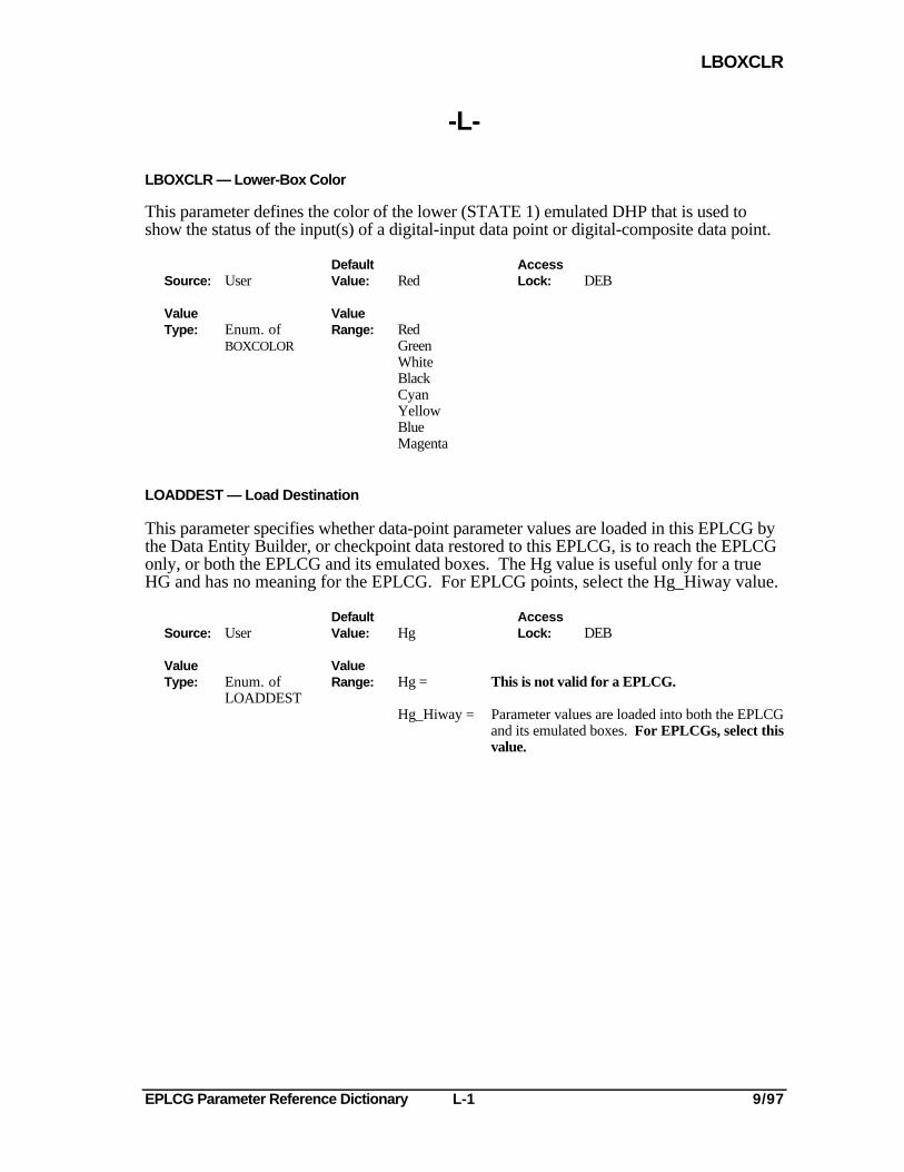
LBOXCLR — Lower-Box Color
This parameter defines the color of the lower (STATE 1) emulated DHP that is used toshow the status of the input(s) of a digital-input data point or digital-composite data point.
Default AccessSource: User Value: Red Lock: DEB
Value ValueType: Enum. of Range: Red
BOXCOLOR GreenWhiteBlackCyanYellowBlueMagenta
LOADDEST — Load Destination
This parameter specifies whether data-point parameter values are loaded in this EPLCG bythe Data Entity Builder, or checkpoint data restored to this EPLCG, is to reach the EPLCGonly, or both the EPLCG and its emulated boxes. The Hg value is useful only for a trueHG and has no meaning for the EPLCG. For EPLCG points, select the Hg_Hiway value.
Default AccessSource: User Value: Hg Lock: DEB
Value ValueType: Enum. of Range: Hg = This is not valid for a EPLCG.
LOADDESTHg_Hiway = Parameter values are loaded into both the EPLCG
and its emulated boxes. For EPLCGs, select thisvalue.

EPLCG Parameter Reference Dictionary L-2 9/97
EPLCG Parameter Reference Dictionary M-1 9/97
MODE
-M-
MODE — Operating Mode
On a configuration form, this parameter does not contain any entries and serves only toremind the user that this data point is in the manual mode after the data point is loadedduring configuration data entry.
During operation, this parameter represents the current operating mode of a data point.
Default AccessSource: User Value: Man Lock: Oper.
ValueType: Enum.
Value Man = Manual mode; an operator or a user-written program controls the outputRange: value, OP, of this point.
Auto = Automatic mode; does not apply to EPLCG data points.
Cas = Cascade mode; continuous-control output connections in an LCN node or auser-written program controls the output value, OP, of this point.
RCASENB must contain On (true) to allow control of OP in Manual or CascadeModes by continuous-control output connections or by user-written programs.
When an operator or discontinuous control program selects the cascade mode for adata point, the data point does not immediately go into the cascade mode. Instead, acascade request (CASREQ) is generated. This condition is displayed at the UniversalStation as "-C" to the right of the current operating mode, and it also indicates to theprimary data point that it may take over control of the data point. Later, when theAM requests the cascade mode, the cascade request is removed and the data point goesinto the remote cascade mode.
The cascade mode applies to analog output and analog composite data points, anddigital output and digital composite data points.
NOTES
1. For analog or digital data points, the requested mode must beeither Man or Cas.
2. Updates to the value in this parameter depend on modeattributes, control interlocks, and the normal mode and normal-mode attribute. Refer to 4.4.3 and 4.4.4 in System ControlFunctions in the Implementation/Startup & Reconfiguration - 2binder.
3. MODE is displayed in reverse video on the Detail Display whenthe value in NMODE differs from that in MODE (except whenNMODE contains None).
EPLCG Parameter Reference Dictionary M-2 9/97
MODEAPPL
MODEAPPL — Array of Applicable Modes
When retrieved, this parameter is a set of four Boolean values that correspond to thefollowing four operating modes: MAN, AUTO, CAS, and BCAS. The values listed below(True and False) indicate which mode is currently allowed for the data point.
Default AccessSource: System Value: N/A Lock: Read-Only
Value ValueType: Boolean Range: True = Mode is allowed.
ArrayFalse = Mode is not allowed.
MODEPERM — Operator Mode Change (Operator Keylock-Access-Level Change Permission)
This parameter defines whether the Operator Keylock-Access Level is allowed to changethe control mode of the data point.
Default AccessSource: User Value: Permit Lock: Engr.
Value ValueType: Enum. of Range: Permit = Operator key level can change the control
MODEPERM mode for this data point.
Nopermit = Operator key level cannot change the controlmode of this data point.
EPLCG Parameter Reference Dictionary M-3 9/97
MOOUTIND
MOOUTIND — Momentary O/P (Output) Indication
This parameter specifies whether the latched single or dual outputs from a digital outputdata point or a digital composite data point are to be momentary ("doorbell" action) ornonmomentary.
Default AccessSource: User Value: Nomoment Lock: DEB
ValueType: Enum. of
MOOUTIND
Value Nomoment = Output from the data point is held in the commanded stateRange: (energized or de-energized) until another command is issued
by the (Upper state change) or (Lower state change)
and the ENTER Keys.
Moment = Output from the data point is held in the commanded state
(energized or de-energized) until the or key isreleased. If Moment is entered, do not make any entry for the RCASENB parameter.Refer to the definition of the OUTIND (Output Indication) parameter for more information.
NOTE
If DIGALFMT=Cinddis, you must ensure that theMOOUTIND parameter contains Nomoment.

EPLCG Parameter Reference Dictionary M-4 9/97
EPLCG Parameter Reference Dictionary N-1 9/97
NAME
-N-
NAME — Tag Name
The Tag Name defines the name of the data point in the system. It is used to identify thedata point in all displays, listings, messages, alarms, etc., throughout the system. Forexample, Figure N-1 shows the location of Tag Name FC100T1 on the Group and DetailDisplays.
Default AccessSource: User Value: All Underscores Lock: DEB
Value ValueType: Entity ID Range: The Tag Name can consist of up to 16 characters, and the
permissible character set is as follows:
Alphabetics A through Z (uppercase only).Numerics 0 through 9 (an all numeric tag name is notpermissible).Underscore (_) cannot be used as the first character or the lastcharacter in the tag name, and consecutive underscores are notallowed.
Embedded space characters are not allowed.
EPLCG Parameter Reference Dictionary N-2 9/97
NAME
GROUP DISPLAY
DETH REFLUX PUMP - A CONTR POINT DESCRIPTOR
F 3HPFC1ØØT1LBS/SECREFLUX
TAG NAME
E. U. DESCRIPTOR
KEYWORD
5Ø.7 5Ø.9U25.9
DETAIL DISPLAYPOINT DESCRIPTOR UNIT IDTAG NAME
UNIT
.ØØ% -
75% -
5Ø% -
25% -
Ø% -
PV
OUT %
MAN
FC1ØØT1 DETH REFLUX PUMP A CONTR XX
F 3HPFC1ØØT1LBS/SECREFLUX
TAG NAME
E. U. DESCRIPTOR
KEYWORD
5Ø.75Ø.9U25.9
Figure N-1 — Location of Terms on Group and Detail Displays 1850
EPLCG Parameter Reference Dictionary N-3 9/97
NCMPTXT1
NCMPTXT1 — Text 1 (Data Hiway Data Point)
This parameter defines a descriptor of up to eight characters that is to be displayed whenboth inputs to a digital data point are noncomplementary (00 or 11), as defined by theZZTEXT (Non-Comp State 00 Text) parameter. If Text1 is entered for ZZTEXT, thisdescriptor is displayed when both inputs are false (00). If Text2 is entered for ZZTEXT,this descriptor is displayed when both inputs are true (11).
Default AccessSource: User Value: Badpv Lock: DEB
Value ValueType: String Range: The permissible character set consists of all characters
on the Engineer's Keyboard. Basically this set consistsof Alphabetics A-Z, Numerics 0-9 and the followingspecial characters: space ! " % & ' ( ) * + - / : ; > < =?__ , . $
NCMPTXT2 — Text 2 (Data Hiway Data Point)
This parameter defines a descriptor of up to eight characters that is to be displayed whenboth inputs to a digital data point are noncomplementary (00 or 11) as defined by theZZTEXT (Non-Comp State 00 Text) parameter. If Text1 is entered for ZZTEXT, thisdescriptor is displayed when both inputs are true (11). If Text2 is entered for ZZTEXT,this descriptor is displayed when both inputs are false (00).
Default AccessSource: User Value: Inbetwn Lock: DEB
Value ValueType: String Range: The permissible character set consists of all characters
on the Engineer's Keyboard. Basically this set consistsof Alphabetics A-Z, Numerics 0-9 and the following specialcharacters: space ! " % & ' ( ) * + - / : ; > < = ? __ , . $
NMBRINPT — Number of Inputs
This parameter defines the number of inputs for a digital input or digital composite datapoint.
If a 2 is entered for this parameter (to specify that a digital data point has two inputs), thesystem automatically assigns the number of the second subslot/data point as described forthe INPTSSLT (Input Subslot/data point) parameter.
Default AccessSource: User Value: 1 Lock: DEB
Value ValueType: Integer Range: 1 = Digital data point has one input.
2 = Digital data point has two inputs.
EPLCG Parameter Reference Dictionary N-4 9/97
NMBROUT
NMBROUT — Number of Outputs
This parameter defines the number of outputs for a digital output or digital composite datapoint.
If a 2 is entered for this parameter (to specify that a digital data point has two outputs), thesystem automatically assigns the number of the second subslot/data point as described forthe OUTSSLT (Output Subslot/data point) parameter.
Default AccessSource: User Value: 1 Lock: DEB
Value Integer ValueType: Range: 1 = Digital data point has one output.
2 = Digital data point has two outputs.
NMODATTR— Normal Mode Attribute
This parameter defines the normal mode attribute. The normal mode attribute is theattribute that is copied into MODATTR when the NORM button is pressed at a UniversalStation (also at that time, the content of NMODE is copied into MODE). This thenbecomes the mode attribute for this point. Refer to 4.4.4 in System Control Functions inthe Implementation/Startup & Reconfiguration - 2 binder.
Default AccessSource: User Value: None Lock: Engr.
Value ValueType: Enum. of Range: Operator = Operator supplies the mode, setpoint, and output
MODEATT value.
Program = Program supplies the mode, setpoint, and outpoint value.
None = The normal mode does not have an attribute.
EPLCG Parameter Reference Dictionary N-5 9/97
NMODE
NMODE — Normal Mode
This parameter defines the normal mode. The normal mode is the mode that is copied intoMODE when the NORM button is pressed at a Universal Station (also at that time, thecontent of NMODATTR is copied into MODATTR). This then becomes the mode for thispoint. Refer to 4.4.4 in System Control Functions in the Implementation/Startup &Reconfiguration - 2 binder.
This parameter is applicable to analog and digital output data points, and analog and digitalcomposite data points.
Default AccessSource: User Value: None Lock: Engr.
Value ValueType: Enum. of Range: None = Normal mode is not configured.
MODEMan = Normal mode is manual.
Auto = Normal mode is automatic.
Cas = Normal mode is cascade.
NOTES
1. MODE/MODATTR is displayed in reverse video when either conflicts with NMODE/NMODATTR,except if NMODE is None.
2. When NMODE = None is selected when the point is built, NMODATTR defaults to None. When anNMODE selection other than None is chosen, the possible values for NMODATTR are None,Operator, and Program.
3. The user can set NMODATTR to None and NMODE to something other than None. In this case,pressing the NORM key results in MODE being changed to the configured NMODE and MODATTRstaying the same.

EPLCG Parameter Reference Dictionary N-6 9/97
EPLCG Parameter Reference Dictionary O-1 9/97
OFFNRMPR
-O-
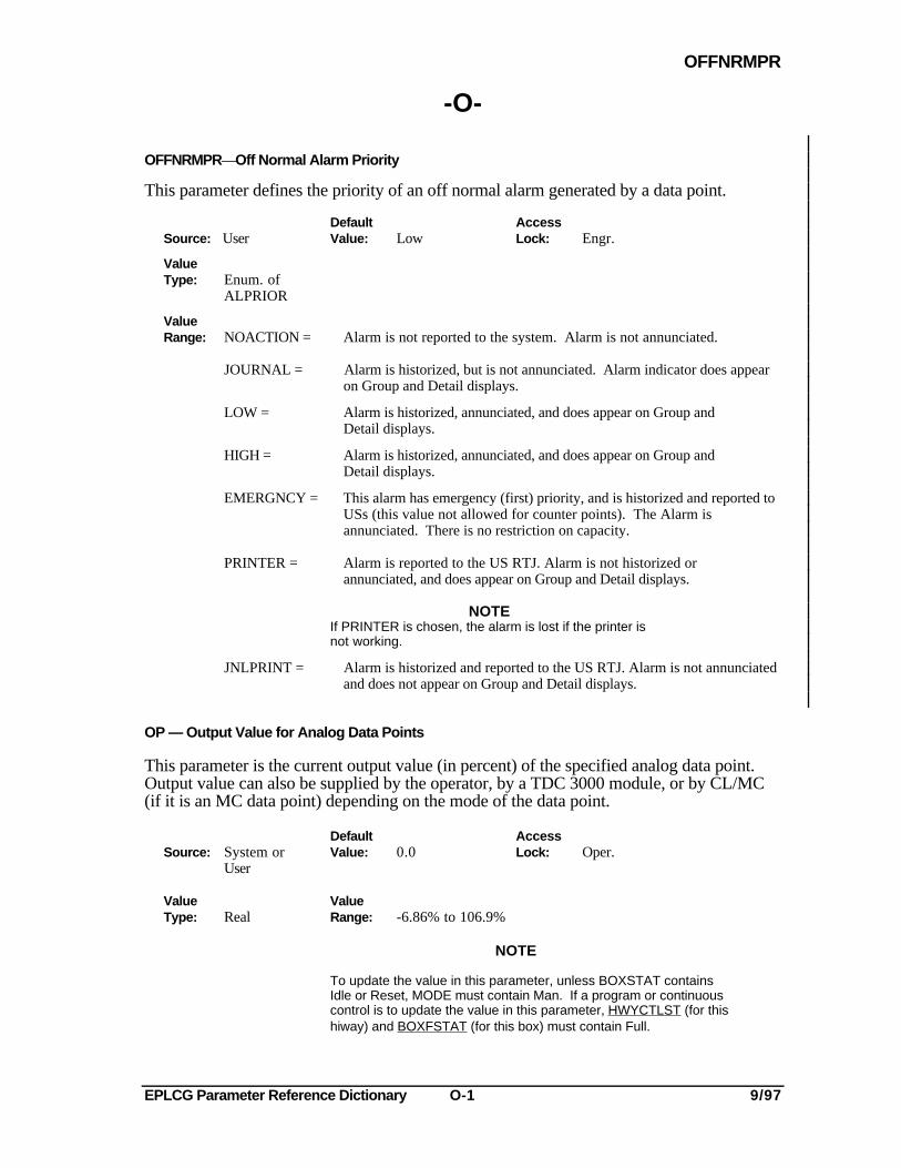
OFFNRMPR—Off Normal Alarm Priority
This parameter defines the priority of an off normal alarm generated by a data point.
Default AccessSource: User Value: Low Lock: Engr.
ValueType: Enum. of
ALPRIOR
ValueRange: NOACTION = Alarm is not reported to the system. Alarm is not annunciated.
JOURNAL = Alarm is historized, but is not annunciated. Alarm indicator does appearon Group and Detail displays.
LOW = Alarm is historized, annunciated, and does appear on Group andDetail displays.
HIGH = Alarm is historized, annunciated, and does appear on Group andDetail displays.
EMERGNCY = This alarm has emergency (first) priority, and is historized and reported toUSs (this value not allowed for counter points). The Alarm isannunciated. There is no restriction on capacity.
PRINTER = Alarm is reported to the US RTJ. Alarm is not historized orannunciated, and does appear on Group and Detail displays.
NOTEIf PRINTER is chosen, the alarm is lost if the printer isnot working.
JNLPRINT = Alarm is historized and reported to the US RTJ. Alarm is not annunciatedand does not appear on Group and Detail displays.
OP — Output Value for Analog Data Points
This parameter is the current output value (in percent) of the specified analog data point.Output value can also be supplied by the operator, by a TDC 3000 module, or by CL/MC(if it is an MC data point) depending on the mode of the data point.
Default AccessSource: System or Value: 0.0 Lock: Oper.
User
Value ValueType: Real Range: -6.86% to 106.9%
NOTE
To update the value in this parameter, unless BOXSTAT containsIdle or Reset, MODE must contain Man. If a program or continuouscontrol is to update the value in this parameter, HWYCTLST (for thishiway) and BOXFSTAT (for this box) must contain Full.
EPLCG Parameter Reference Dictionary O-2 9/97
OP
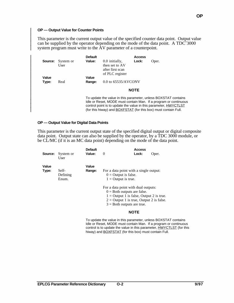
OP — Output Value for Counter Points
This parameter is the current output value of the specified counter data point. Output valuecan be supplied by the operator depending on the mode of the data point. A TDC 3000system program must write to the AV parameter of a counterpoint.
Default AccessSource: System or Value: 0.0 initially, Lock: Oper.
User then set to AVafter first scanof PLC register
Value ValueType: Real Range: 0.0 to 65535/AVCONV
NOTE
To update the value in this parameter, unless BOXSTAT containsIdle or Reset, MODE must contain Man. If a program or continuouscontrol point is to update the value in this parameter, HWYCTLST(for this hiway) and BOXFSTAT (for this box) must contain Full.
OP — Output Value for Digital Data Points
This parameter is the current output state of the specified digital output or digital compositedata point. Output state can also be supplied by the operator, by a TDC 3000 module, orbe CL/MC (if it is an MC data point) depending on the mode of the data point.
Default AccessSource: System or Value: 0 Lock: Oper.
User
Value ValueType: Self- Range: For a data point with a single output:
Defining 0 = Output is false.Enum. 1 = Output is true.
For a data point with dual outputs:0 = Both outputs are false.1 = Output 1 is false, Output 2 is true.2 = Output 1 is true, Output 2 is false.3 = Both outputs are true.
NOTE
To update the value in this parameter, unless BOXSTAT containsIdle or Reset, MODE must contain Man. If a program or continuouscontrol is to update the value in this parameter, HWYCTLST (for thishiway) and BOXFSTAT (for this box) must contain Full.
EPLCG Parameter Reference Dictionary O-3 9/97
OPCRDOP
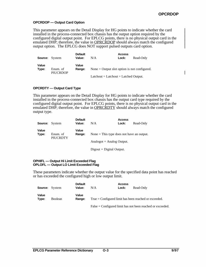
OPCRDOP — Output Card Option
This parameter appears on the Detail Display for HG points to indicate whether the cardinstalled in the process-connected box chassis has the output option required by theconfigured digital output point. For EPLCG points, there is no physical output card in theemulated DHP; therefore, the value in OPRCRDOP should always match the configuredoutput option. The EPLCG does NOT support pulsed outputs card option.
Default AccessSource: System Value: N/A Lock: Read-Only
Value ValueType: Enum. of Range: None = Output slot option is not configured.
PIUCRDOPLatchout = Latchout = Latched Output.
OPCRDTY — Output Card Type
This parameter appears on the Detail Display for HG points to indicate whether the cardinstalled in the process-connected box chassis has the output card type required by theconfigured digital output point. For EPLCG points, there is no physical output card in theemulated DHP; therefore, the value in OPRCRDTY should always match the configuredoutput type.
Default AccessSource: System Value: N/A Lock: Read-Only
Value ValueType: Enum. of Range: None = This type does not have an output.
PIUCRDTYAnalogot = Analog Output.
Digout = Digital Output.
OPHIFL — Output Hi Limit Exceeded FlagOPLOFL — Output LO Limit Exceeded Flag
These parameters indicate whether the output value for the specified data point has reachedor has exceeded the configured high or low output limit.
Default AccessSource: System Value: N/A Lock: Read-Only
Value ValueType: Boolean Range: True = Configured limit has been reached or exceeded.
False = Configured limit has not been reached or exceeded.
EPLCG Parameter Reference Dictionary O-4 9/97
OUTBOXNM
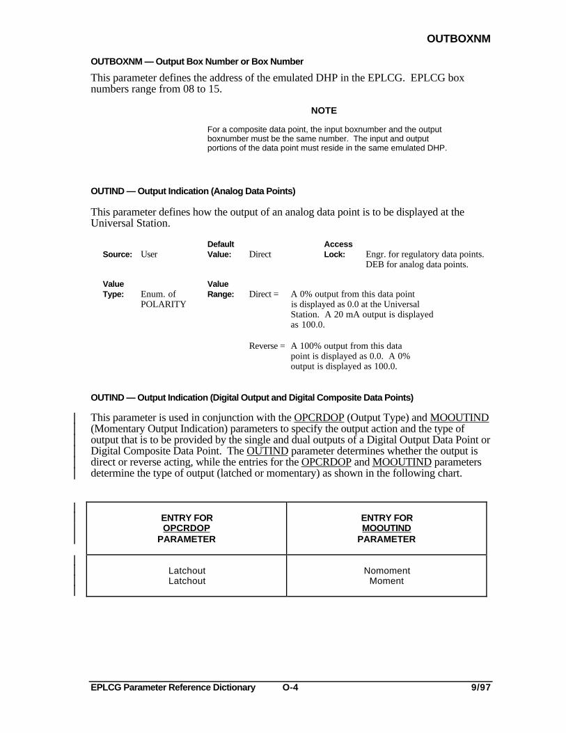
OUTBOXNM — Output Box Number or Box Number
This parameter defines the address of the emulated DHP in the EPLCG. EPLCG boxnumbers range from 08 to 15.
NOTE
For a composite data point, the input boxnumber and the outputboxnumber must be the same number. The input and outputportions of the data point must reside in the same emulated DHP.
OUTIND — Output Indication (Analog Data Points)
This parameter defines how the output of an analog data point is to be displayed at theUniversal Station.
Default AccessSource: User Value: Direct Lock: Engr. for regulatory data points.
DEB for analog data points.
Value ValueType: Enum. of Range: Direct = A 0% output from this data point
POLARITY is displayed as 0.0 at the UniversalStation. A 20 mA output is displayedas 100.0.
Reverse = A 100% output from this data point is displayed as 0.0. A 0%output is displayed as 100.0.
OUTIND — Output Indication (Digital Output and Digital Composite Data Points)
This parameter is used in conjunction with the OPCRDOP (Output Type) and MOOUTIND(Momentary Output Indication) parameters to specify the output action and the type ofoutput that is to be provided by the single and dual outputs of a Digital Output Data Point orDigital Composite Data Point. The OUTIND parameter determines whether the output isdirect or reverse acting, while the entries for the OPCRDOP and MOOUTIND parametersdetermine the type of output (latched or momentary) as shown in the following chart.
ENTRY FOROPCRDOP
PARAMETER
ENTRY FORMOOUTIND
PARAMETER
LatchoutLatchout
NomomentMoment
EPLCG Parameter Reference Dictionary O-5 9/97
OUTIND
Default AccessSource: User Value: Direct Lock: DEB
Value Enum. ofType: POLARITY
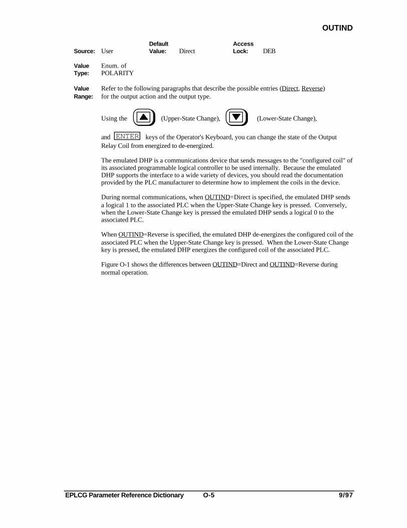
Value Refer to the following paragraphs that describe the possible entries (Direct, Reverse)Range: for the output action and the output type.
Using the (Upper-State Change), (Lower-State Change),
and ENTER keys of the Operator's Keyboard, you can change the state of the OutputRelay Coil from energized to de-energized.
The emulated DHP is a communications device that sends messages to the "configured coil" ofits associated programmable logical controller to be used internally. Because the emulatedDHP supports the interface to a wide variety of devices, you should read the documentationprovided by the PLC manufacturer to determine how to implement the coils in the device.
During normal communications, when OUTIND=Direct is specified, the emulated DHP sendsa logical 1 to the associated PLC when the Upper-State Change key is pressed. Conversely,when the Lower-State Change key is pressed the emulated DHP sends a logical 0 to theassociated PLC.
When OUTIND=Reverse is specified, the emulated DHP de-energizes the configured coil of theassociated PLC when the Upper-State Change key is pressed. When the Lower-State Changekey is pressed, the emulated DHP energizes the configured coil of the associated PLC.
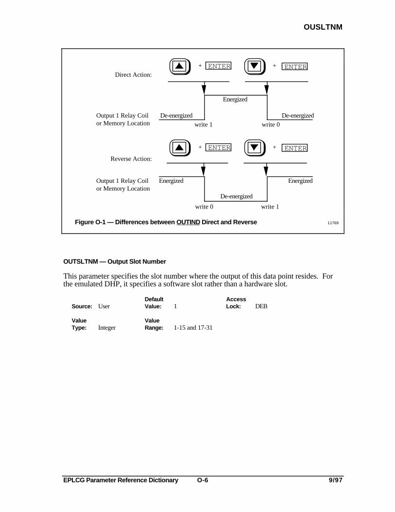
Figure O-1 shows the differences between OUTIND=Direct and OUTIND=Reverse duringnormal operation.
EPLCG Parameter Reference Dictionary O-6 9/97
OUSLTNM
Direct Action:
Output 1 Relay Coilor Memory Location
De-energized
Energized
Reverse Action:
ENTER+ + ENTER
De-energized
Energized Energized
De-energized
ENTER+ + ENTER
Output 1 Relay Coilor Memory Location
write 1 write 0
write 0 write 1
Figure O-1 — Differences between OUTIND Direct and Reverse 11769
OUTSLTNM — Output Slot Number
This parameter specifies the slot number where the output of this data point resides. Forthe emulated DHP, it specifies a software slot rather than a hardware slot.
Default AccessSource: User Value: 1 Lock: DEB
Value ValueType: Integer Range: 1-15 and 17-31
EPLCG Parameter Reference Dictionary O-7 9/97
OUTSSLT
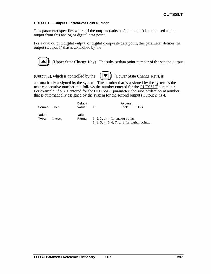
OUTSSLT — Output Subslot/Data Point Number
This parameter specifies which of the outputs (subslots/data points) is to be used as theoutput from this analog or digital data point.
For a dual output, digital output, or digital composite data point, this parameter defines theoutput (Output 1) that is controlled by the
(Upper State Change Key). The subslot/data point number of the second output
(Output 2), which is controlled by the (Lower State Change Key), is
automatically assigned by the system. The number that is assigned by the system is thenext consecutive number that follows the number entered for the OUTSSLT parameter.For example, if a 3 is entered for the OUTSSLT parameter, the subslot/data point numberthat is automatically assigned by the system for the second output (Output 2) is 4.
Default AccessSource: User Value: 1 Lock: DEB
Value ValueType: Integer Range: 1, 2, 3, or 4 for analog points.
1, 2, 3, 4, 5, 6, 7, or 8 for digital points.
EPLCG Parameter Reference Dictionary O-8 9/97
OVERVAL
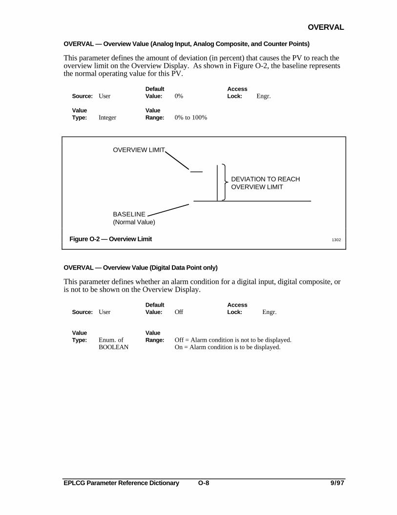
OVERVAL — Overview Value (Analog Input, Analog Composite, and Counter Points)
This parameter defines the amount of deviation (in percent) that causes the PV to reach theoverview limit on the Overview Display. As shown in Figure O-2, the baseline representsthe normal operating value for this PV.
Default AccessSource: User Value: 0% Lock: Engr.
Value ValueType: Integer Range: 0% to 100%
OVERVIEW LIMIT
BASELINE(Normal Value)
DEVIATION TO REACHOVERVIEW LIMIT
Figure O-2 — Overview Limit 1302
OVERVAL — Overview Value (Digital Data Point only)
This parameter defines whether an alarm condition for a digital input, digital composite, oris not to be shown on the Overview Display.
Default AccessSource: User Value: Off Lock: Engr.
Value ValueType: Enum. of Range: Off = Alarm condition is not to be displayed.
BOOLEAN On = Alarm condition is to be displayed.
EPLCG Parameter Reference Dictionary P-1 9/97
PARSEC
-P-
PARSEC — # of Parameters Per Second (All Processor Status Data Points)
This parameter defines the number of parameters fetched from this node.
Default AccessSource: System Value: 0.0 Lock: Operator
Value ValueType: Real Range: ≥ 0.0
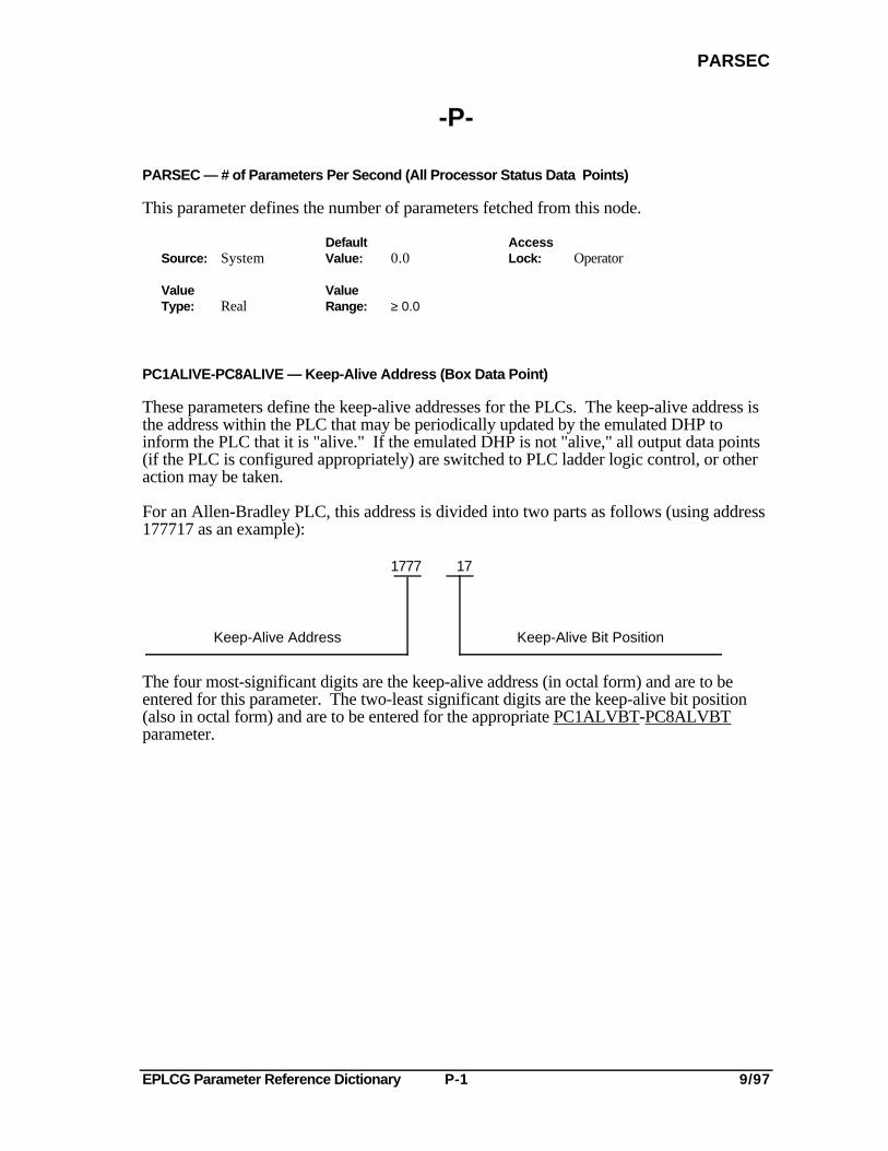
PC1ALIVE-PC8ALIVE — Keep-Alive Address (Box Data Point)
These parameters define the keep-alive addresses for the PLCs. The keep-alive address isthe address within the PLC that may be periodically updated by the emulated DHP toinform the PLC that it is "alive." If the emulated DHP is not "alive," all output data points(if the PLC is configured appropriately) are switched to PLC ladder logic control, or otheraction may be taken.
For an Allen-Bradley PLC, this address is divided into two parts as follows (using address177717 as an example):
Keep-Alive Address Keep-Alive Bit Position
1777 17
The four most-significant digits are the keep-alive address (in octal form) and are to beentered for this parameter. The two-least significant digits are the keep-alive bit position(also in octal form) and are to be entered for the appropriate PC1ALVBT-PC8ALVBTparameter.
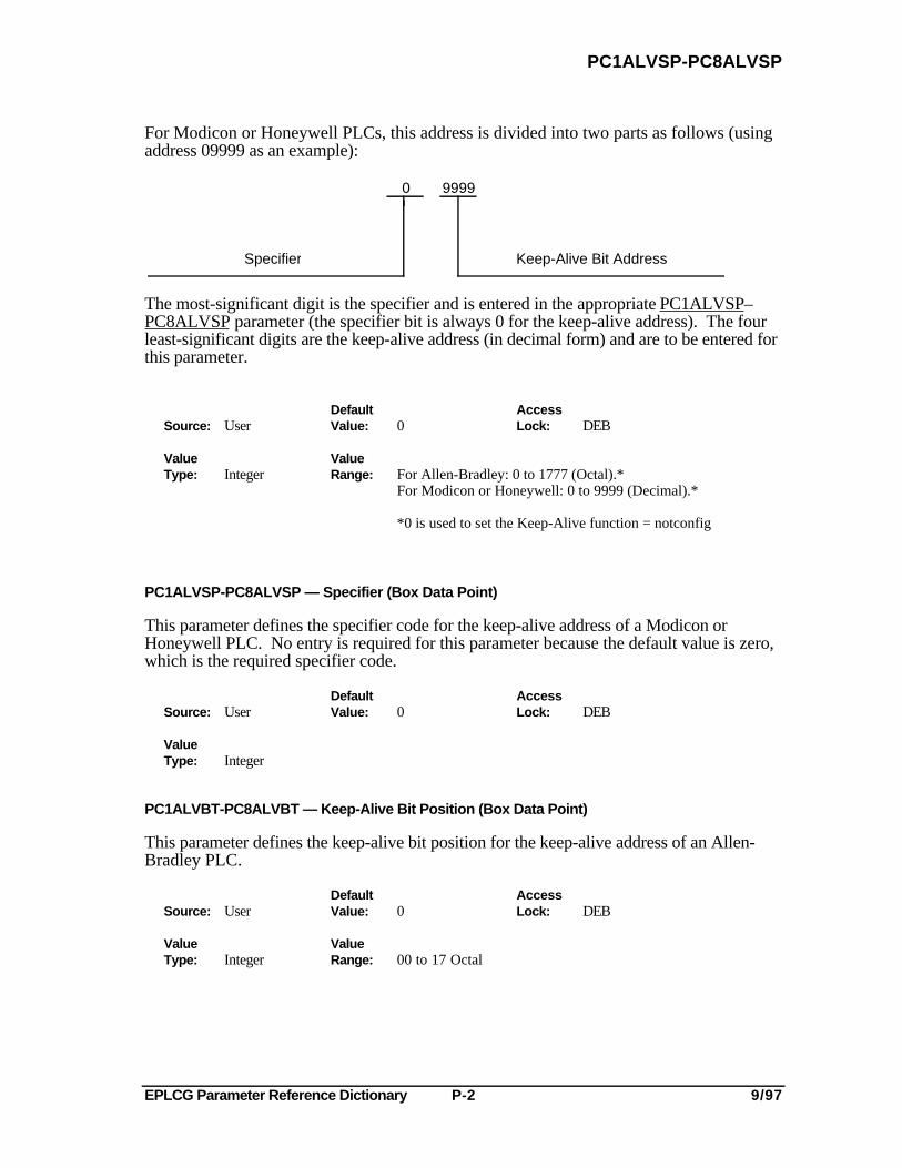
EPLCG Parameter Reference Dictionary P-2 9/97
PC1ALVSP-PC8ALVSP
For Modicon or Honeywell PLCs, this address is divided into two parts as follows (usingaddress 09999 as an example):
9999 0
Specifier Keep-Alive Bit Address
The most-significant digit is the specifier and is entered in the appropriate PC1ALVSP–PC8ALVSP parameter (the specifier bit is always 0 for the keep-alive address). The fourleast-significant digits are the keep-alive address (in decimal form) and are to be entered forthis parameter.
Default AccessSource: User Value: 0 Lock: DEB
Value ValueType: Integer Range: For Allen-Bradley: 0 to 1777 (Octal).*
For Modicon or Honeywell: 0 to 9999 (Decimal).*
*0 is used to set the Keep-Alive function = notconfig
PC1ALVSP-PC8ALVSP — Specifier (Box Data Point)
This parameter defines the specifier code for the keep-alive address of a Modicon orHoneywell PLC. No entry is required for this parameter because the default value is zero,which is the required specifier code.
Default AccessSource: User Value: 0 Lock: DEB
ValueType: Integer
PC1ALVBT-PC8ALVBT — Keep-Alive Bit Position (Box Data Point)
This parameter defines the keep-alive bit position for the keep-alive address of an Allen-Bradley PLC.
Default AccessSource: User Value: 0 Lock: DEB
Value ValueType: Integer Range: 00 to 17 Octal

EPLCG Parameter Reference Dictionary P-3 9/97
PC1PORT-PC8PORT
PC1PORT- PC8PORT — Port Number (Box Data Point)
This parameter defines which of the two EPLCG port numbers is assigned to this PLC.The EPLCG has only two physical ports. Logical port numbers 3 and 4 represent physicalports 1 and 2, respectively.
Default AccessSource: User Value: 1 Lock: DEB
Value ValueType: Integer Range: 1 or 2 - Modicon or Allen-Bradley Data Scan
3 or 4 - Allen-Bradley Report by Exception3 or 4 - Honeywell/Modbus: Do not track PLC ladder logic
changes to digital or analog outputs
PC1PORTA-PC8PORTA — Port Address (Box Data Point)
This parameter defines the address of the PLC on the connected PLC network.
Default AccessSource: User Value: 0 Lock: DEB
Value ValueType: Integer Range: 0 = Undefined.
1-376 octal - Allen-Bradley1-247 decimal - Modicon or Honeywell
PC1TYPE-PC8TYPE — PC1-PC8 Model Type (Box Data Point)
This parameter defines the model type of this PLC.
Default AccessSource: User Value: Notconfg Lock: DEB
Value ValueType: Enum. of Range: If Modicon has been entered for BOXPROT parameter:
PCTYPENotconfg = Not configuredM384 = Model Type 384 (or GE 6/60)M484 = Model Type 484 (or GE 6/600)M584 = Model Type 584 (or GE 6/600)
Select M584 if a Modicon 884 or 984 is to be used.
If Allenbrd has been entered for BOXPROT:
Aplc = Model Type PLC -3 or -5 communicating values in binary.
Aplc2=PLC2 communication values in BCDAplc215=PLC2/15 communication values in BCD or Logical (see Note)Aplc220=PLC2/20 communication values in BCDAplc230=PLC2/30 communication values in BCDAminPLC2=Min2 communication values in BCD
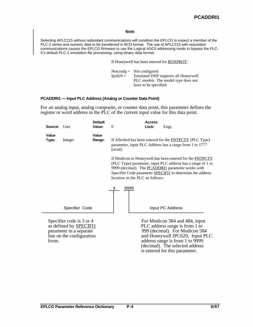
EPLCG Parameter Reference Dictionary P-4 9/97
PCADDRI1
Note
Selecting APLC215 without redundant communications will condition the EPLCG to expect a member of thePLC-2 series and numeric data to be transferred in BCD format. The use of APLC215 with redundantcommunications causes the EPLCG firmware to use the Logical ASCII addressing mode to bypass the PLC-5’s default PLC-2 emulation file processing, using binary data format.
If Honeywell has been entered for BOXPROT:
Notconfg = Not configuredIpc620 = Emulated DHP supports all Honeywell
PLC models The model type does not have to be specified.
PCADDRI1 — Input PLC Address (Analog or Counter Data Point)
For an analog input, analog composite, or counter data point, this parameter defines theregister or word address in the PLC of the current input value for this data point.
Default AccessSource: User Value: 0 Lock: Engr.
Value ValueType: Integer Range: If Allenbrd has been entered for the PNTPCTY (PLC Type)
parameter, input PLC Address has a range from 1 to 1777 (octal).
If Modicon or Honeywell has been entered for the PNTPCTY(PLC Type) parameter, input PLC address has a range of 1 to9999 (decimal). The PCADDRI1 parameter works withSpecifier Code parameter SPECIFI1 to determine the addresslocation in the PLC as follows:
99994
Input PC AddressSpecifier Code
Specifier code is 3 or 4 For Modicon 384 and 484, inputas defined by SPECIFI1 PLC address range is from 1 toparameter in a separate 999 (decimal). For Modicon 584line on the configuration and Honeywell IPC620, Input PLCform. address range is from 1 to 9999
(decimal). The selected addressis entered for this parameter.
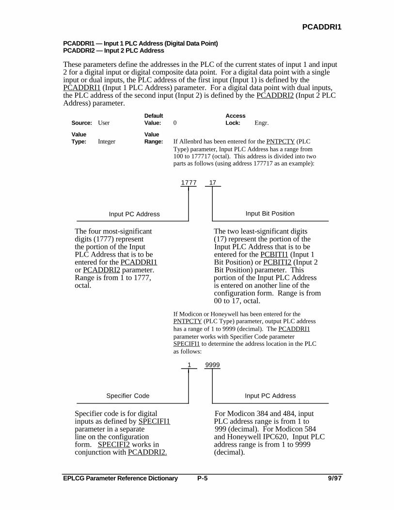
EPLCG Parameter Reference Dictionary P-5 9/97
PCADDRI1
PCADDRI1 — Input 1 PLC Address (Digital Data Point)PCADDRI2 — Input 2 PLC Address
These parameters define the addresses in the PLC of the current states of input 1 and input2 for a digital input or digital composite data point. For a digital data point with a singleinput or dual inputs, the PLC address of the first input (Input 1) is defined by thePCADDRI1 (Input 1 PLC Address) parameter. For a digital data point with dual inputs,the PLC address of the second input (Input 2) is defined by the PCADDRI2 (Input 2 PLCAddress) parameter.
Default AccessSource: User Value: 0 Lock: Engr.
Value ValueType: Integer Range: If Allenbrd has been entered for the PNTPCTY (PLC
Type) parameter, Input PLC Address has a range from 100 to 177717 (octal). This address is divided into two parts as follows (using address 177717 as an example):
Input Bit Position
17 1777
Input PC Address
The four most-significant The two least-significant digitsdigits (1777) represent (17) represent the portion of thethe portion of the Input Input PLC Address that is to bePLC Address that is to be entered for the PCBITI1 (Input 1entered for the PCADDRI1 Bit Position) or PCBITI2 (Input 2or PCADDRI2 parameter. Bit Position) parameter. ThisRange is from 1 to 1777, portion of the Input PLC Addressoctal. is entered on another line of the
configuration form. Range is from00 to 17, octal.
If Modicon or Honeywell has been entered for thePNTPCTY (PLC Type) parameter, output PLC addresshas a range of 1 to 9999 (decimal). The PCADDRI1parameter works with Specifier Code parameterSPECIFI1 to determine the address location in the PLCas follows:
9999
Input PC Address
1
Specifier Code
Specifier code is for digital For Modicon 384 and 484, inputinputs as defined by SPECIFI1 PLC address range is from 1 toparameter in a separate 999 (decimal). For Modicon 584line on the configuration and Honeywell IPC620, Input PLCform. SPECIFI2 works in address range is from 1 to 9999conjunction with PCADDRI2. (decimal).
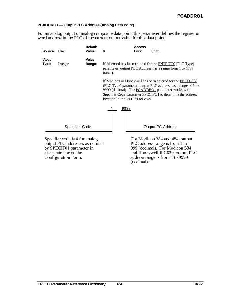
EPLCG Parameter Reference Dictionary P-6 9/97
PCADDRO1
PCADDRO1 — Output PLC Address (Analog Data Point)
For an analog output or analog composite data point, this parameter defines the register orword address in the PLC of the current output value for this data point.
Default AccessSource: User Value: 0 Lock: Engr.
Value ValueType: Integer Range: If Allenbrd has been entered for the PNTPCTY (PLC Type)
parameter, output PLC Address has a range from 1 to 1777 (octal).
If Modicon or Honeywell has been entered for the PNTPCTY(PLC Type) parameter, output PLC address has a range of 1 to9999 (decimal). The PCADDRO1 parameter works withSpecifier Code parameter SPECIFO1 to determine the addresslocation in the PLC as follows:
9999 4
Specifier Code Output PC Address
Specifier code is 4 for analog For Modicon 384 and 484, outputoutput PLC addresses as defined PLC address range is from 1 toby SPECIF01 parameter in 999 (decimal). For Modicon 584a separate line on the and Honeywell IPC620, output PLCConfiguration Form. address range is from 1 to 9999
(decimal).
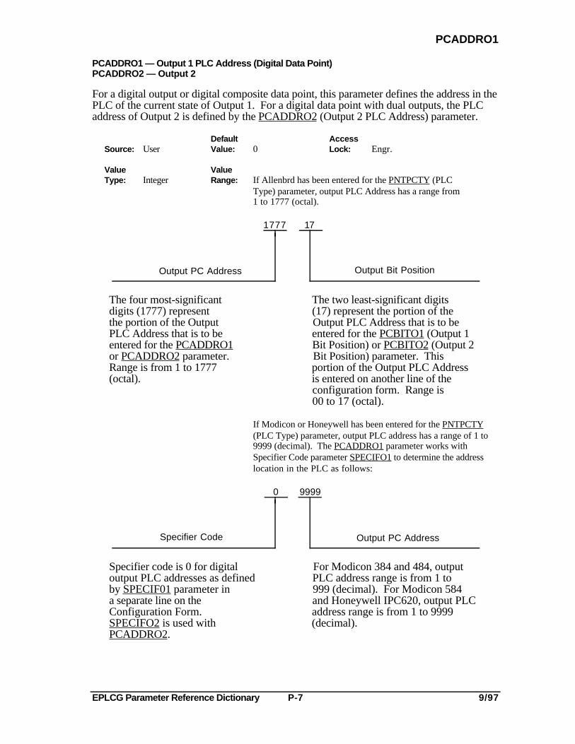
EPLCG Parameter Reference Dictionary P-7 9/97
PCADDRO1
PCADDRO1 — Output 1 PLC Address (Digital Data Point)PCADDRO2 — Output 2
For a digital output or digital composite data point, this parameter defines the address in thePLC of the current state of Output 1. For a digital data point with dual outputs, the PLCaddress of Output 2 is defined by the PCADDRO2 (Output 2 PLC Address) parameter.
Default AccessSource: User Value: 0 Lock: Engr.
Value ValueType: Integer Range: If Allenbrd has been entered for the PNTPCTY (PLC
Type) parameter, output PLC Address has a range from 1 to 1777 (octal).
Output Bit Position
17 1777
Output PC Address
The four most-significant The two least-significant digitsdigits (1777) represent (17) represent the portion of thethe portion of the Output Output PLC Address that is to bePLC Address that is to be entered for the PCBITO1 (Output 1entered for the PCADDRO1 Bit Position) or PCBITO2 (Output 2or PCADDRO2 parameter. Bit Position) parameter. ThisRange is from 1 to 1777 portion of the Output PLC Address(octal). is entered on another line of the
configuration form. Range is00 to 17 (octal).
If Modicon or Honeywell has been entered for the PNTPCTY(PLC Type) parameter, output PLC address has a range of 1 to9999 (decimal). The PCADDRO1 parameter works withSpecifier Code parameter SPECIFO1 to determine the addresslocation in the PLC as follows:
9999 0
Specifier Code Output PC Address
Specifier code is 0 for digital For Modicon 384 and 484, outputoutput PLC addresses as defined PLC address range is from 1 toby SPECIF01 parameter in 999 (decimal). For Modicon 584a separate line on the and Honeywell IPC620, output PLCConfiguration Form. address range is from 1 to 9999SPECIFO2 is used with (decimal).PCADDRO2.

EPLCG Parameter Reference Dictionary P-8 9/97
PCBITI1
PCBITI1 — Input 1 Bit Position (Digital Data Point)PCBITI2 — Input 2 Bit Position
These parameters define the two least-significant digits (in octal form) of the Input PCAddress when Allenbrd (Allen-Bradley) has been entered for the PNTPCTY (PC Type)parameter. PCBITI1 is used in conjunction with PCADDRI1 (Input 1 PC Address);PCBITI2 is used in conjunction with PCADDRI2 (Input 2 PC Address).
Default AccessSource: User Value: 00 Lock: Engr.
Value ValueType: Integer Range: 00-17 (Octal)
PCBITO1 — Output 1 Bit Position (Digital Data Point)PCBITO2 — Output 2 Bit Position
These parameters define the two least-significant digits (in octal form) of the Output PCAddress when Allenbrd (Allen-Bradley) has been entered for the PNTPCTY (PC Type)parameter. PCBITO1 is used in conjunction with PCADDRO1 (Output 1 PC Address);PCBITO2 is used in conjunction with PCADDRO2 (Output 2 PC Address).
Default AccessSource: User Value: 00 Lock: Engr.
Value ValueType: Integer Range: 00-17 (Octal)
PCCONFI1 — PLC Bad Configuration Status for Input 1PCCONFI2 — PLC Bad Configuration Status for Input 2
These parameters indicate whether the input or inputs to an emulated DHP data point havebeen configured properly. Parameter PCCONFI1 is applicable to all emulated DHP analogand digital data points; PCCONFI2 is applicable to only the second input of digital datapoints that have dual inputs. The values of PCCONFI1 and PCCONFI2 are set by theemulated DHP.
Default AccessSource: System Value: N/A Lock: Read-Only
Value ValueType: Enum. of Range: Notconfg = This input has not been configured.
PCCONFGUncertn = Configuration of this input has not been
checked.
Bad = This input has been configured incorrectly.
Ok = This input has been configured correctly.
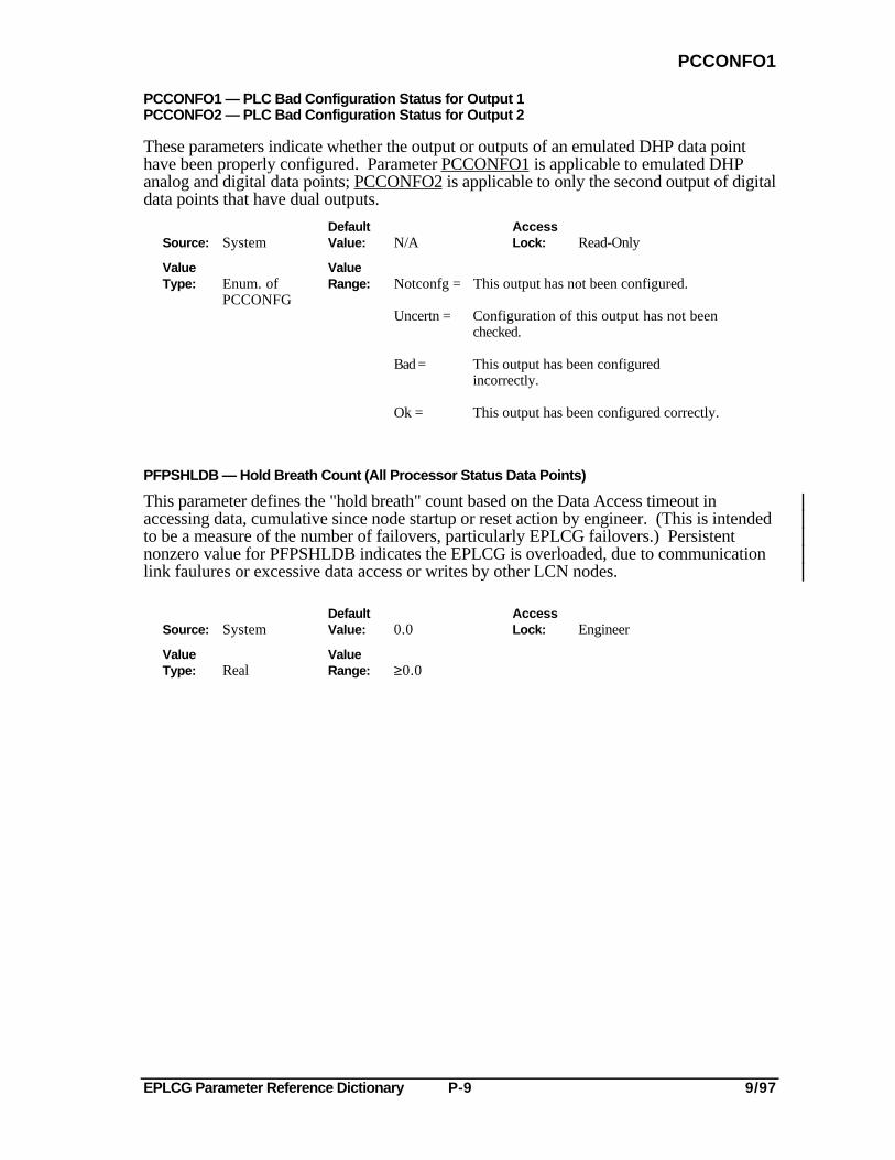
EPLCG Parameter Reference Dictionary P-9 9/97
PCCONFO1
PCCONFO1 — PLC Bad Configuration Status for Output 1PCCONFO2 — PLC Bad Configuration Status for Output 2
These parameters indicate whether the output or outputs of an emulated DHP data pointhave been properly configured. Parameter PCCONFO1 is applicable to emulated DHPanalog and digital data points; PCCONFO2 is applicable to only the second output of digitaldata points that have dual outputs.
Default AccessSource: System Value: N/A Lock: Read-Only
Value ValueType: Enum. of Range: Notconfg = This output has not been configured.
PCCONFGUncertn = Configuration of this output has not been
checked.
Bad = This output has been configuredincorrectly.
Ok = This output has been configured correctly.
PFPSHLDB — Hold Breath Count (All Processor Status Data Points)
This parameter defines the "hold breath" count based on the Data Access timeout inaccessing data, cumulative since node startup or reset action by engineer. (This is intendedto be a measure of the number of failovers, particularly EPLCG failovers.) Persistentnonzero value for PFPSHLDB indicates the EPLCG is overloaded, due to communicationlink faulures or excessive data access or writes by other LCN nodes.
Default AccessSource: System Value: 0.0 Lock: Engineer
Value ValueType: Real Range: ≥0.0
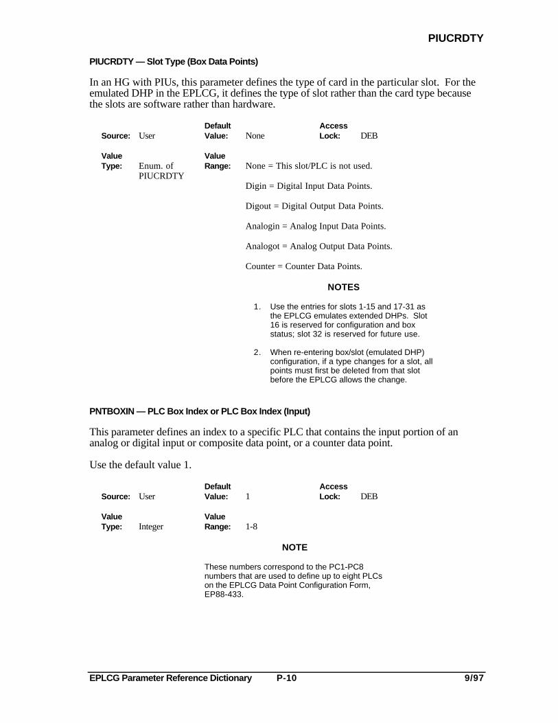
EPLCG Parameter Reference Dictionary P-10 9/97
PIUCRDTY
PIUCRDTY — Slot Type (Box Data Points)
In an HG with PIUs, this parameter defines the type of card in the particular slot. For theemulated DHP in the EPLCG, it defines the type of slot rather than the card type becausethe slots are software rather than hardware.
Default AccessSource: User Value: None Lock: DEB
Value ValueType: Enum. of Range: None = This slot/PLC is not used.
PIUCRDTYDigin = Digital Input Data Points.
Digout = Digital Output Data Points.
Analogin = Analog Input Data Points.
Analogot = Analog Output Data Points.
Counter = Counter Data Points.
NOTES
1. Use the entries for slots 1-15 and 17-31 asthe EPLCG emulates extended DHPs. Slot16 is reserved for configuration and boxstatus; slot 32 is reserved for future use.
2. When re-entering box/slot (emulated DHP)configuration, if a type changes for a slot, allpoints must first be deleted from that slotbefore the EPLCG allows the change.
PNTBOXIN — PLC Box Index or PLC Box Index (Input)
This parameter defines an index to a specific PLC that contains the input portion of ananalog or digital input or composite data point, or a counter data point.
Use the default value 1.
Default AccessSource: User Value: 1 Lock: DEB
Value ValueType: Integer Range: 1-8
NOTE
These numbers correspond to the PC1-PC8numbers that are used to define up to eight PLCson the EPLCG Data Point Configuration Form,EP88-433.
EPLCG Parameter Reference Dictionary P-11 9/97
PNTBOXOT
PNTBOXOT — PLC Box Index or PLC Box Index (Output)
This parameter defines the address of the PLC that contains the output portion of an analogor digital output or composite data point.
Default AccessSource: User Value: 1 Lock: DEB
Value ValueType: Integer Range: 1-8
NOTE
These numbers correspond to the PC1-PC8numbers that are used to define up to eight PLCson the EPLCG Data Point Configuration Form,EP88-433.
PNTBOXTY — Box Type
This parameter defines the type of hiway box in which the data point specified by NAME(Tag Name) resides.
Default AccessSource: User Value: Undefined Lock: DEB
Value ValueType: Enum. of Range: Dhp = Data Hiway Port. This is the only valid EPLCG value.
BOXTYPE
The following are not valid values for the EPLCG:Cb = Basic Controller.Ec = Extended Controller.Hlpiu = High Level Process Interface Unit.Lepiu = Low Energy Process Interface Unit.Llpiu = Low Level Process Interface Unit.Mc = Multifunction Controller.
EPLCG Parameter Reference Dictionary P-12 9/97
PNTPCTY
PNTPCTY — PLC Type
This parameter defines the manufacturer of the PLCs that are connected to this DHP.
Default AccessSource: User Value: Allenbrd Lock: DEB
Value ValueType: Enum. of Range: Allenbrd = Allen-Bradley.
BOXPROTModicon = Modicon (if other Modicon emulator PLCs
are to be used, select Modicon as the entryfor this parameter).
Honywell = Honeywell.
PNTSTATE — Point State
This parameter provides an indication of the current point state. For the most part, thepoint state is the same as the emulated DHP state.
Default AccessSource: System Value: N/A Lock: Read-Only
Value ValueType: Enum. of Range: Uncertn = No emulated hiway security tests have been performed
PNTTYPE or hiway status is uncertain.
Ok = Box data point is operating properly.
Failed = Emulated DHP has failed.
Reset = Emulated DHP is in reset state.
Test = Emulated DHP is being tested.
EPLCG Parameter Reference Dictionary P-13 9/97
PNTTYPE
PNTTYPE — Point Type
This parameter defines the type of data point.
Default AccessSource: System Value: Null Lock: Read-Only
Value ValueType: Enum. of Range: Null = This is not a data point.
PNTTYPE Analgin = Analog Input Data Point.Analgout = Analog Output Data Point.Analgcom = Analog Composite Data Point.Digin = Digital Input Data Point.Digout = Digital Output Data Point.Digcom = Digital Composite Data Point.Counter = Counter Data Point.
NOTE
The list above applies to EPLCG data point types only. For acomplete list of HG data points, see the parameter entry forPNTTYPE in the HG Parameter Reference Dictionary.
POLLRES — # of Poll Responses (HG Processor Status Points)
This parameter exists in the EPLCG, but has no meaning. In the HG, it defines thenumber of hiway poll responses of DHI board data during the last 15-second sampleperiod.
POLLS — # of Hiway Polls (HG Processor Status Data Points)
This parameter exists in the EPLCG, but has no meaning. In the HG, it defines thenumber of hiway polls of DHI board data during the last 15-second sample period.
PRESET — Preset Value (Counter Data Point)
This parameter specifies the value at which a counter data point goes into an alarmcondition (accumulated value exceeds the preset value). This parameter is a EPLCG valueonly and cannot be written to a PLC counter parameter.
Default AccessSource: User Value: 0 Lock: Oper.
Value ValueType: Real Range: For emulated DHP Counter Data Point: 0 to 65535*AVCONV
* If the value entered exceeds the maximum value, theEPLCG clamps it to the maximum value.
PRIMMOD — Primary Module Point ID
The primary module point identifier is the Tag Name of a process module to which a datapoint can be assigned. Refer to the definition of NAME (Tag Name) for the valid characterset.
EPLCG Parameter Reference Dictionary P-14 9/97
PTDESC
PTDESC — Point Descriptor
The point descriptor is used to describe the data point, and it appears on the Group andDetail Displays for this data point. In the example shown in Figure N-1 (see NAME), thepoint descriptor is DETH REFLUX PUMP A CONTR. The point descriptor appears onthe Group Display only when the data point is selected.
Default AccessSource: User Value: All Blanks Lock: DEB
Value ValueType: String Range: The point descriptor can consist of up to 24 characters,
and the permissible character set consists of allcharacters on the Engineer's Keyboard. Basically thisset consists of Alphabetics A-Z, Numerics 0-9, space,and the following special characters: ! " % & ' ( ) *+ - / : ; > < = ? _ , . $
PTDISCL — Point Disclosure
This parameter determines whether the Data Entity Builder's parameter entry display is toshow the complete set of user-configurable parameters or a smaller set of the parameters,leaving the parameters not displayed at the default values.
Default AccessSource: User Value: Brief Lock: DEB
Value ValueType: Enum. of Range: Brief = The brief set of configurable parameters is
PTDISCL displayed on the parameter entry display. If this entryis selected, default values are supplied by the DEB for parameters that do not appear on the parameter entry display.
Full = The full set of configurable parameters is displayed on the parameter entry display.
PTEXECST — Point Execution State
This parameter indicates the execution state of the specified data point.
Default AccessSource: System Value: N/A Lock: Read-Only
Value ValueType: Enum. of Range: Notconfg = This is a transient state; configuration has
PTEXECST not been completed for this data point.
Active = Data point is running.
Inactive = Data point is fully configured but is not running.
EPLCG Parameter Reference Dictionary P-15 9/97
PTINAL
PTINAL — Point in Alarm
This parameter indicates whether an alarm condition exists on this point.
Default AccessSource: System Value: Off Lock: Read-Only
Value ValueType: Boolean Range: Off = Point is not in alarm.
On = Point is in alarm.
PTSESTBL — # of Established Process Points (All Processor Status Data Points)
This parameter defines the number of process points currently established in this node.
Default AccessSource: System Value: 0 Lock: Read-Only
Value ValueType: Integer Range: 0-32767
PV — Current State (PV) (Digital Data Points)
This parameter provides the current state of the specified data point.
Default AccessSource: System Value: N/A Lock: Supvr.
Value ValueType: Self- Range: For a single input digital data point:
Defining 0 = Input is true.Enum. 1 = Input is false.
For a dual input digital data point:0 = Both inputs are false.1 = Input 1 is false, Input 2 is true.2 = Input 1 is true, Input 2 is false.3 = Both inputs are true.
PV — Current Value of PV (Analog Data Points)
This parameter provides the current value of the PV input (in engineering units) at thespecified data point.
Default AccessSource: System Value: N/A Lock: Supvr.
Value ValueType: Real Range: -6.86% to 106.9% percent of scale in engineering units.
EPLCG Parameter Reference Dictionary P-16 9/97
PVALDB
PVALDB — PV Alarm Deadband ( Analog Input Data Points)
This parameter is not used in PLCG/EPLCG and should be ignored. PVALDB defines thealarm deadband for the PV high limit and PV low limit for analog input points for the HG.
PVAUTO — PV Automatic
This parameter is the current PV value (in engineering units) that is read from the emulatedDHP. This parameter is used in conjunction with the PV parameter when the PVSOURCE ismanual or substituted. For these values of PVSOURCE, the PV is read/stored to the EPLCGdatabase; it is not read from the process box. This allows you to see the manual/substitutedPV value (PV) as well as the PV value from the process box (PVAUTO).
Default AccessSource: System Value: N/A Lock: Read-Only
Value ValueType: Real Range: -6.86% to 106.9% of scale in engineering units.
PVCLAMP — Clamp Value Option
This parameter defines whether the PV value is clamped when it is outside the configuredrange established by PVEULO and PVEUHI. If the PV is clamped, it is clamped to thenearest end-point of the extended range as specified by the PV range-option parameterPVRNGOP. Refer to Tables P-1.
Default AccessSource: User Value: Noclamp Lock: Engr.
ValueType: Enum. of Value:
PVCLAMP Range: Noclamp = PV values outside the configured range are notclamped to the specified extended range. PV is displayed as "------" (Not A Number).
Clmp = Configured range is clamped to the specified extendedrange and the clamped value is displayed for the PV.
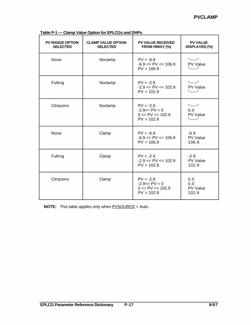
EPLCG Parameter Reference Dictionary P-17 9/97
PVCLAMP
Table P-1 — Clamp Value Option for EPLCGs and DHPs
PV RANGE OPTION CLAMP VALUE OPTION PV VALUE RECEIVED PV VALUESELECTED SELECTED FROM HIWAY (%) DISPLAYED (%)
None Noclamp PV < -6.9 "------"-6.9 <= PV <= 106.9 PV ValuePV > 106.9 "------"
Fullrng Noclamp PV < -2.9 "------"-2.9 <= PV <= 102.9 PV ValuePV > 102.9 "------"
Clmpzero Noclamp PV < -2.9 "------"-2.9<= PV < 0 0.00 <= PV <= 102.9 PV ValuePV > 102.9 "------"
None Clamp PV < -6.9 -6.9-6.9 <= PV <= 106.9 PV ValuePV > 106.9 106.9
Fullrng Clamp PV < -2.9 -2.9-2.9 <= PV <= 102.9 PV ValuePV > 102.9 102.9
Clmpzero Clamp PV < -2.9 0.0-2.9<= PV < 0 0.00 <= PV <= 102.9 PV ValuePV > 102.9 102.9
NOTE: This table applies only when PVSOURCE = Auto.
EPLCG Parameter Reference Dictionary P-18 9/97
PVDSPHI
PVDSPHI — PV Display Range HighPVDSPLO— PV Display Range Low
These parameters are present only if the HG Display Range option has been purchased forthe system. These parameters allow an engineer to specify for this point, a differentdisplay range (0% to 100%) for the PV value on Group and Detail displays than the PVrange defined by PVEUHI and PVEULO. If the option is not present or if NaN is enteredin these parameters, the display range is defined by PVEUHI and PVEULO.
Default AccessSource: User Value: NaN (- - - ) Lock: Engr.
Value ValueType: Real Range: Within the range defined by PVEULO and PVEUHI, but
not exactly equal to either value. See the description of theseparameters for further details.
PVEUHI — PV Range HighPVEULO — PV Range Low
For analog inputs, RNGCODE1 defines the input values that correspond to the high andlow engineering-units limits specified in PVEULO and PVEUHI, respectively. For analogoutputs, RNGCODE2 defines the output values that correspond to the 0% to 100% outputvalue range.
Default AccessSource: User Value: 100.0 for PVEUHI Lock: Engr.
0.0 for PVEULO
Value ValueType:Real Range: -9999 to 9999
NOTE
The values for PVEUHI and PVEULO are stored both in the EPLCG and inthe emulated DHP. When a change in the PVEUHI or PVEULO valueoccurs, the values for the following parameters (also stored both in theEPLCG and the emulated DHP) are updated in the EPLCG: PVEUHI,PVEULO, and PVTEMP or PVFORMAT (depending on the value inPVCHAR—linear types use PVFORMAT and temperature type usePVTEMP).
These parameters represent the high and low ends of the EU range for thePV. The maximum, total range allowed is 10000.0 units. For example, ifPVEULO contains -10000.0, PVEUHI can be no higher than 0.0 units.Similarly, if PVEULO contains 0.0, PVEUHI can be no higher than 10000.0units.
EPLCG Parameter Reference Dictionary P-19 9/97
PVFORMAT
Because PVEUHI represents the span of the PV range, a change to thevalue in PVEULO can affect the value in PVEUHI. For example, if PVEULOinitially contains 0.0 and PVEUHI contains 1000.0, and then an engineerchanges PVEULO to 100.0, PVEUHI is automatically adjusted to 1100.0, toretain the span of 1000.0 units. The span can be changed only by updatingthe value in PVEUHI.
PVFORMAT — Decimal FormatPVFORMAT — Decimal Format of X
This parameter defines the position of the decimal point for values in analog data points.
Default AccessSource: User Value: D0 Lock: Engr.
Value ValueType: Enum. of Range: For all data points except
VALFORMAT numeric data points:D0 = +XXXXD1 = +XXX.XD2 = +XX.XXD3 = +X.XXX
NOTE
To update the value in this parameter, MODE must contain Man.
The value for this parameter is stored both in the EPLCG and theemulated DHP. When a change to this value occurs, the values inthe following parameters are also updated: PVEUHI, PVEULO, andPVCHAR.
EPLCG Parameter Reference Dictionary P-20 9/97
PVHIPR
PVHIPR — PV High PriorityPVLOPR — PV Low Priority
These parameters define high and low priority levels for PV alarms.
Default AccessSource: User Value: Low Lock: Engr.
ValueType: Enum. of
ALPRIOR
ValueRange: NOACTION = Alarm is not reported to the system. Alarm is not annunciated.
JOURNAL = Alarm is historized, but is not annunciated. Alarm indicator does appearon Group and Detail displays.
LOW = Alarm is historized, annunciated, and does appear on Group andDetail displays.
HIGH = Alarm is historized, annunciated, and does appear on Group andDetail displays.
EMERGNCY = This alarm has emergency (first) priority, and is historized and reported toUSs (this value not allowed for counter points). The Alarm isannunciated. There is no restriction on capacity.
PRINTER = Alarm is reported to the US RTJ. Alarm is not historized orannunciated, and does appear on Group and Detail displays.
NOTEIf PRINTER is chosen, the alarm is lost if the printer isnot working.
JNLPRINT = Alarm is historized and reported to the US RTJ. Alarm is not annunciatedand does not appear on Group and Detail displays.
EPLCG Parameter Reference Dictionary P-21 9/97
PVHITP
PVHITP — PV High Trip PointPVLOTP — PV Low Trip Point
These parameters define the high and low trip point values (in engineering units) of the PVthat cause an alarm condition to be generated. (PVHITP and PVLOTP are applicable toanalog data points.)
Default AccessSource: User Value: 0.0 Lock: Supvr.
Value ValueType: Real Range: PVHITP = -6.9% to 106.9 % of full scale in
engineering units.
PVLOTP = -6.9% to 106.9% of full scale inengineering units.
Engineering unit range is from -9999 to 9999. Fullscale in engineering units is defined by values assignedto PVEULO and PVEUHI.
Ranges for PVHHTP, PVHHHTP, PVLLTP andPVLLLTP are the same as described above for PVHITPand PVLOTP.
NOTE
PVLOTP cannot be set higher than PVHITP; otherwise, anunreasonable value alarm condition can exist.
PVRNGOP — PV Range Option
This parameter defines the range of the PV input for analog data points.
Default AccessSource: User Value: None Lock: Engr.
Value ValueType: Enum. of Range: None = -6.9% to 106.9 % (no clamping).
PVRNGOP Fullrng = -2.9% to 102.9% (no clamping).Clmpzero = 0.0% to 102.9% (clamped at zero).
EPLCG Parameter Reference Dictionary P-22 9/97
PVSOURCE
PVSOURCE — PV Source (Analog and Digital Data Points)
This parameter indicates the source of the PV value and which access levels, if any, arepermitted to change the PV value.
Default AccessSource: User Value: Auto Lock: Supvr.
Value ValueType: Enum. of Range: Auto = Automatic; the PV value is obtained from the hiway
PVSOURCE box. Changes to the PV value are not allowed.
Man = Manual; operator, supervisor, or engineer access level can be used to change the PV.
Sub = Substituted; program and continuous control access levels in an LCN node can be used to change the PV value of this data point.
NOTE
When this parameter contains Man or Sub, you can still see thevalue from the process in the PVAUTO parameter. When the valuein PVSOURCE is changed from Man or Sub to Auto, the values inPVAUTO and in PV should be made the same, to avoid a "bump."
PVSTS — PV Value Status
This parameter provides the current status of the PV value for the specified data point.
Default AccessSource: System Value: N/A Lock: Read-Only
Value ValueType: Enum. of Range: Normal = PV value is OK.
PVVALSTUncertn = PV value is uncertain.
Bad = PV value is bad.
PVTV — Target
This parameter defines the target (setpoint) value in engineering units for analog input datapoints and for the input portion of analog-composite data points.
Default AccessSource: User Value: 0.0 Lock: Oper.
Value ValueType: Real Range: Target value can have a range from -6.9% to 106.9%.
Value that is entered is defined by the configured rangeestablished by PVEULO and PVEUHI.
EPLCG Parameter Reference Dictionary R-1 9/97
RCASENB-R-
RCASENB — Remote Cascade Enable
This parameter specifies whether a control output connection or a continuous controlprogram in an LCN node can control the output of this EPLCG point. If you needmore information, see 4.4.4.3 in System Control Functions.
This parameter does not apply to a digital data point if Moment has been entered for theMOOUTIND (Momentary Output Indication) parameter.
Default AccessSource: User Value: Off Lock: Engr.
Value ValueType: Boolean Range: On = A continuous control program device can control the OP
value from this point. Off = Prevents program control of the OP value from this
point.
NOTE
To update the value in this parameter, MODE must contain Man andCASREQ must contain Notreq.
RNGCODE1 — PLC Range Code for Analog InputsRNGCODE2 — PLC Range Code for Analog Outputs
These parameters are used for analog input, analog output, and analog composite datapoints to specify the range that is to be used by the DHP when it converts PLC values toB12E format. RNGCODE1 is used for analog input data points, and for the input portionof analog composite data points; RNGCODE2 is used for analog output data points, andfor the output portion of analog composite data points.
Default AccessSource: User Value: 0 Lock: DEB
Value ValueType: Integer Range: 0 = 0-999 (Use for A-B PLC-2 and Modicon)
1 = 0-4095 (Use for A-B PLC 3 -5); binary2 = 0-9999 (Can be used for A-B); PLC 3,5
with BCD or binary values.3-7 = Defaults to 0-9999
For analog inputs, RNGCODE1 is used with PVEULO, PVEUHI to define the Engineering Unit (EU) range of RNGCODE1.
For analog outputs, RNGCODE2 defines 0-100% output (the only units of outputs on the LCN).
EPLCG Parameter Reference Dictionary R-2 9/97
RPARSEC
RPARSEC — # of Read Parameter Requests (All Processor Status Data Points)
This parameter defines the cumulative number of read parameter requests to any LCN nodesince node startup or last reset action by engineer. Indicate the number of parameter readrequests from this node to any LCN node.
Default AccessSource: System Value: 0.0 Lock: Engr.
Value ValueType: Real Range: ≥ 0.0
EPLCG Parameter Reference Dictionary S-1 9/97
SCANTIME
-S-
SCANTIME — Scan Time (Sec) (Box Data Point)
This parameter defines the scan time (in seconds) during which the emulated DHP updatesall the PLC data points in the emulated DHP database. A scan time of 0 seconds isconsidered as being free-running, and is the only valid value for EPLCGs (0 is forced).
Default AccessSource: User Value: 0 seconds Lock: DEB
Value ValueType: Integer Range: 00 (free running)
SLOTNUM — Slot Number or Input Slot Number
This parameter defines the slot number of the emulated slot where this particular data pointresides in the emulated DHP. For analog input and digital input and composite data points,and counter data points, the slot number defines the slot where the input to the data pointresides.
Default AccessSource: User Value: 1 Lock: DEB
Value ValueType: Integer Range: The slot number ranges for the various data points are as follows:
Data Point Type Slot Number Range
All 1-15, 17-31
SOESYNCH — SOE Synchronization (EPLCG Data Point)
Sequence-of-events reporting is not available in a EPLCG, so the only valid value isDisable.
Default AccessSource: User Value: Disable Lock: DEB
Value ValueType: Enum. of Range: Disable = Select this value for EPLCGs.
ENBLSTAT
Enable = Not a valid value for EPLCGs.
EPLCG Parameter Reference Dictionary S-2 9/97
SP
SP—Setpoint Value (Counter Data Point)
This parameter defines the 100% range of the OP bar graph in the detail or group display.
Default AccessSource: User Value: 0.0 Lock: Oper.
Value ValueType: Real Range: For emulated DHP Counter Data Point: 0 to 65535*AVCON
* If the value entered exceeds the maximum value, the EPLCGclamps it to the maximum value.
SPARSEC — # of Store Parameters Requests (All Processor Status Data Points)
This parameter defines the number of store parameters requests per second to any LCNnode.
Default AccessSource: System Value: 0.0 Lock: Engr.
Value ValueType: Real Range: ≥ 0.0
SPECIFI1 — Specifier Code or Input 1 Specifier Code
Used only with Modicon or Modbus compatible PLCs, this parameter specifies whether theinput PLC address is that of an analog input, digital input, or a counter. SPECIFI1 can beused as the specifier code for a digital data point with one input, or for the first input (Input1) of a digital data point that has two inputs.
Default AccessSource: User Value: 0 Lock: Engr.
Value ValueType: Integer Range: For Analog Input: 3 (Modicon input register) or 4
For Digital Input: 0 or 1 (one bit) or 4 (holding register withpacked digitals)For Counter Input: 4
SPECIFO1 — Specifier Code or Output 1 Specifier Code
Used only with Modicon or Modbus compatible PLCs, this parameter specifies whether theoutput PLC address is that of an analog composite, analog output, digital composite, ordigital output data point. SPECIFO1 is also used as the specifier code for a digital datapoint with one output, or for the first output (Output 1) of a digital data point that has twooutputs.
Default AccessSource: User Value: 0 Lock: Engr.
Value ValueType: Integer Range: For Analog Data Point: 4
For Digital Data Point: 0
EPLCG Parameter Reference Dictionary S-3 9/97
SPECIFI2
SPECIFI2 — Input 2 Specifier Code (Digital Data Point)
This parameter specifies that the input PLC address is that of the second input (Input 2) of adigital data point that has two inputs.
Default AccessSource: User Value: 0 Lock: Engr.
Value ValueType: Integer Range: For Digital Input: 0 or 1 (one bit) or 4 (holding register with
packed digitals)
SPECIFO2 — Output 2 Specifier Code (Digital Data Point)
Used only with Modicon or Modbus compatible PLCs, this parameter specifies that theoutput PLC address is that of the second output (Output 2) of a digital output or digitalcomposite data point that has two outputs.
Default AccessSource: User Value: 0 Lock: Engr.
Value ValueType: Integer Range: For Digital Data Point: 0
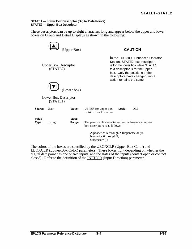
EPLCG Parameter Reference Dictionary S-4 9/97
STATE1–STATE2
STATE1 — Lower Box Descriptor (Digital Data Points)STATE2 — Upper Box Descriptor
These descriptors can be up to eight characters long and appear below the upper and lowerboxes on Group and Detail Displays as shown in the following:
(Upper Box) CAUTION
In the TDC 3000 Enhanced OperatorStation, STATE2 text descriptor
Upper Box Descriptor is for the lower box while STATE1(STATE2) text descriptor is for the upper
box. Only the positions of thedescriptors have changed; inputaction remains the same.
(Lower box)
Lower Box Descriptor(STATE1)
Source: User Value: UPPER for upper box. Lock: DEBLOWER for lower box.
Value ValueType: String Range: The permissible character set for the lower- and upper-
box descriptors is as follows:
Alphabetics A through Z (uppercase only),Numerics 0 through 9,Underscore (_)
The colors of the boxes are specified by the UBOXCLR (Upper-Box Color) andLBOXCLR (Lower-Box Color) parameters. These boxes light depending on whether thedigital data point has one or two inputs, and the states of the inputs (contact open or contactclosed). Refer to the definition of the INPTDIR (Input Direction) parameter.
EPLCG Parameter Reference Dictionary T-1 9/97
TOGINTSL
-T-
TOGINTSL — Slot/PLC 1-n TOG Interval (Box Data Point)
This parameter defines which time-out interval (BOXTOG1 (TOG Interval 1) orBOXTOG2 (TOG Interval 2)) parameter is to be used for the specified slot/PLC in thisemulated DHP.
Default AccessSource: User Value: Interv1 Lock: Engr.
Value ValueType: Enum. of Range: Interv1 = Time-out interval specified by BOXTOG1
SLOTTOGS parameter is to be used for this slot/PLC.Interv2 = Time-out interval specified by BOXTOG2
parameter is to be used for this slot/PLC.

EPLCG Parameter Reference Dictionary T-2 9/97
EPLCG Parameter Reference Dictionary U-1 9/97
UBOXCLR
-U-
UBOXCLR — Upper-Box Color
This parameter defines the color of the upper (STATE2) box that is used to show the statusof the input(s) at a digital input or digital composite data point.
Default AccessSource: User Value: Red Lock: DEB
Value ValueType: Enum. of Range: Red
BOXCOLOR GreenWhiteBlackCyanYellowBlueMagenta
UNIT — Unit ID
This parameter defines the unit to which this data point is assigned. The unit identifierappears on the Detail Display for this data point as shown in Figure N-1, and in otherdisplays and listings throughout the system. In the example shown in Figure N-1, the unitidentifier is XX. (The unit identifiers are originally defined during network configuration.)
Default AccessSource: User Value: All Blanks Lock: DEB
Value ValueType: String Range: The unit identifier can consist of one or two characters
and the valid character set is as follows:
Alphabetics A through Z (uppercase only).Numerics 0 through 9 (an all numeric identifier ispermissible).Underscores are not permitted.No leading blanks (spaces).A single character with a trailing space is not permitted.
Restriction: After a unit identifier has been defined, itshould be written exactly the same wayeach time when the same identifier is tobe used. As an example, if the unitidentifier was defined as 03, it should bewritten as 03 and not as 3 for each usageof this unit identifier.
A Real number is returned for this parameter by the Picture Editor and by CL. This number isequivalent to the ordinal number in the enumeration list of units.

EPLCG Parameter Reference Dictionary U-2 9/97
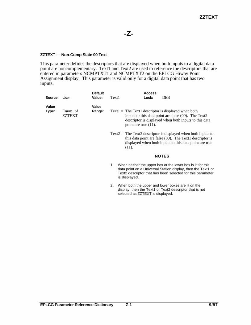
EPLCG Parameter Reference Dictionary Z-1 9/97
ZZTEXT
-Z-
ZZTEXT — Non-Comp State 00 Text
This parameter defines the descriptors that are displayed when both inputs to a digital datapoint are noncomplementary. Text1 and Text2 are used to reference the descriptors that areentered in parameters NCMPTXT1 and NCMPTXT2 on the EPLCG Hiway PointAssignment display. This parameter is valid only for a digital data point that has twoinputs.
Default AccessSource: User Value: Text1 Lock: DEB
Value ValueType: Enum. of Range: Text1 = The Text1 descriptor is displayed when both
ZZTEXT inputs to this data point are false (00). The Text2descriptor is displayed when both inputs to this datapoint are true (11).
Text2 = The Text2 descriptor is displayed when both inputs tothis data point are false (00). The Text1 descriptor isdisplayed when both inputs to this data point are true(11).
NOTES
1. When neither the upper box or the lower box is lit for thisdata point on a Universal Station display, then the Text1 orText2 descriptor that has been selected for this parameteris displayed.
2. When both the upper and lower boxes are lit on thedisplay, then the Text1 or Text2 descriptor that is notselected as ZZTEXT is displayed.

EPLCG Parameter Reference Dictionary Z-2 9/97
FAX Transmittal FAX No.: (602) 313-4842
TO: G. Cacciatore Total FAX pages:(including this page)
Reader CommentsTitle of Document: EPLCG Parameter Reference Dictionary
Document Number: EP09-440 Issue Date: 9/97
Comments:
Recommendations:
FROM:Name: Date:
Title:
Company:
Address:
City: State: ZIP:
Telephone: FAX:
You may also call 800-822-7673 (available in the 48 contiguous states except Arizona; in Arizona dial602-313-5558, or write to:
Honeywell Inc.Industrial Automation and ControlAutomation College2820 West Kelton LanePhoenix, AZ 85023-3028


Industrial Automation and Control Helping You Control Your World
Automation College
2820 W. Kelton Lane
Phoenix, AZ 85023-3028