enhancement of forestry tree planting machine
TRANSCRIPT

University of Strathclyde
Mechanical and Aerospace Engineering
ME519 Group Project
Enhancement of Forestry
Tree Planting Machine
Kirk Johnston
Isabel Chong Cheung
Fraser Henderson
Graeme Queen
Kazuki Iida (Semester 1)
Project Advisor: Prof David Nash
Industrial Representative: Mr William McArthur MIRT/SOE/CILT
Report Submitted: 21st March 2016
Website Address: www.craobhplanting.wix.com/craobhplanting

i
Abstract A team of 5th year Mechanical Engineering students were tasked with designing a new best
in class mechanical tree planter. Working alongside a simulation company called Simultech,
the group must produce a full Computer Aided Design (CAD) model of their chosen design.
Simultech intend to use the CAD model to create a simulation programme for training
purposes.
Roles were allocated to each member of the team, based on strengths working in a group
environment. A detailed project plan was created leading to a contract being agreed
between the team, Simultech and the academic advisor. A critical analysis was conducted on
current planting methods used in Scotland, as well as other forestry equipment and related
areas of interest. The critical analysis allowed a product design specification to be produced
and this was presented and accepted by Simultech and the academic advisor.
As part of the critical analysis, and in order to gain a better understanding of the industry,
the team completed several site visits. The visits consisted of meetings with people working
in the forestry industry and viewing forestry equipment. Some of the site visits have been to
other heavy engineering industries in order to gain a better understanding of things such as
hydraulic systems. The critical analysis enabled the team to gain a solid understanding of the
forestry industry and currently available planting machinery.
As a result of the critical analysis, the decision was made to base the design on improving the
current Bracke P11a planter. The mound quality and the reduction of manual sapling loading
time were identified as the areas where significant improvement was needed. Conceptual
designs were produced to solve each problem with many different options considered. The
group designed a new scarification blade for the Bracke. The blade incorporates a serrated
leading edge and trapezoidal blade shape that provides better soil containment and
compaction. A fast loading system has been designed to allow all the tree saplings to be
loaded simultaneously. These new designs reduced machine downtime for loading as well as
increasing mound quality which leads to greater survival rates. A 3D CAD model of the
original Bracke P11.a and the new planting machine were produced for comparison.

ii
Acknowledgements The group wish to extend great appreciation to Professor David Nash for advising the project
and Mr William McArthur from Simultech Scotland for providing endless support over the
project duration. Further, the group wish to acknowledge the following persons and
companies for accommodating visits and providing assistance in their respective areas of
expertise:
Andrew Campbell – ScotJCB
Mick Bottomley – BSW Timber Group
Jock McKie – John Deere Forestry
Bill Jones and James Hand – Forestry Commission Scotland
Aileen Gray and Neil Watson– Simultech Scotland
Rafael Martínez – Universidad de Valencia
Malcolm Harris – Hytec Hydraulics
Brian McCamon and staff – Christie Elite Nurseries
Jas P Wilson
Edinburgh Trams
Bracke Forest
ECM Vehicle Movers
Helac Inc.
Enterprise Rent-A-Car
William Clark – Clark Engineering
Jose González Pérez – Universidad de Oviedo (EPI GijÓn)
Jill Hodge – Trees for Life
Jake Williams – Bogancloch
Peter Livingstone – Eadha Enterprises
Chris Cameron – University of Strathclyde MAE Department
MAE Administration Staff – University of Strathclyde
MAE Stores – University of Strathclyde

iii
Contents Abstract ..................................................................................................................................... i
Acknowledgements .................................................................................................................. ii
Nomenclature ......................................................................................................................... vi
1.0 Project Definition ............................................................................................................... 1
1.1 Task Outline ................................................................................................................... 1
1.2 Contract.......................................................................................................................... 1
2.0 Project Business ................................................................................................................. 2
2.1 Team Management and Structure ................................................................................. 2
2.2 Stage Gate Process ......................................................................................................... 4
2.3 Communication .............................................................................................................. 6
2.3.1 Internal Communication ......................................................................................... 6
2.3.2 External Communication ......................................................................................... 6
2.4 Media Presence.............................................................................................................. 6
2.5 Finance ........................................................................................................................... 7
2.6 Document Control .......................................................................................................... 9
2.7 Project Plan .................................................................................................................. 11
2.7.1 Updated Plan ......................................................................................................... 11
2.8 Risk Management ........................................................................................................ 12
3.0 Critical Analysis ................................................................................................................ 14
3.1 Planting Environment .................................................................................................. 14
3.2 Existing Planting Machines/Methods .......................................................................... 16
3.2.1 Bracke P11.a .......................................................................................................... 16
3.2.2 EcoPlanter ............................................................................................................. 17
3.2.3 Risutec ................................................................................................................... 18
3.2.4 M Planter............................................................................................................... 18
3.2.5 Overall Comparison of Planting Machines ............................................................ 19
3.3 Future Concepts for Planting Machines ....................................................................... 19
3.3.1 Eco-Friendly Tree Planting Robot.......................................................................... 19
3.3.2 Tree Planting Drone .............................................................................................. 21
3.4 Forestry Machinery ...................................................................................................... 21
3.4.1 Harvester ............................................................................................................... 21
3.4.2 Harvester Heads .................................................................................................... 22
3.4.3 Forwarders ............................................................................................................ 23
3.4.4 Skidders ................................................................................................................. 23
3.4.5 Cable Skidders ....................................................................................................... 24

iv
3.4.6 Grapple Skidders ................................................................................................... 24
3.4.7 Engcon Tiltrotator ................................................................................................. 24
3.4.8 Helac Powertilt ...................................................................................................... 25
3.5 Hydraulics ..................................................................................................................... 25
3.5.1 Basic Principle ....................................................................................................... 25
3.5.2 Hydraulic Pressure and Force ............................................................................... 26
3.5.3 Hydraulics within Excavators and Forestry Machinery ......................................... 26
3.6 Industrial Contact ......................................................................................................... 27
3.6.1 Scot JCB ................................................................................................................. 27
3.6.2 Forestry Commission Scotland .............................................................................. 27
3.6.3 John Deere Forestry .............................................................................................. 28
3.6.4 BSW Timber Group ............................................................................................... 28
3.6.5 Dulnain Plant Hire/Christie Elite Nurseries ........................................................... 28
4.0 Design ............................................................................................................................... 29
4.1 Identifying the Challenges............................................................................................ 29
4.1.1 Product Design Specification (PDS) ....................................................................... 29
4.2 Morphological Chart .................................................................................................... 30
4.3 Power Design ............................................................................................................... 30
4.3.1 Soil Bulk Density and Weight ................................................................................ 30
4.3.2 Machine Hydraulic Power Output and Breakout Force ........................................ 31
4.3.3 Ground Pressure ................................................................................................... 33
4.3.4 Hydraulic Circuit .................................................................................................... 34
4.4 Unchanged Components.............................................................................................. 38
4.4.1 Dibble cylinder Design .......................................................................................... 39
4.4.2 Universal Hitch Analysis ........................................................................................ 41
4.5 Design Improvement Focus ......................................................................................... 42
4.5.1 Hydraulic Leveller .................................................................................................. 42
4.5.2 Scarifying Blade ..................................................................................................... 44
4.5.3 Sapling Reloading .................................................................................................. 56
4.6 Final Models for Simulation ......................................................................................... 75
4.6.1 Existing Bracke P11.a Model ................................................................................. 75
4.6.2 Craobh Planting Enhanced Model ........................................................................ 76
5.0 Reflection ......................................................................................................................... 76
5.1 Design Process Reflection ............................................................................................ 76
5.2 Project Management Reflection .................................................................................. 77
5.3 3D Printing Challenges ................................................................................................. 79

v
5.4 Academic vs. Industrial Representatives ..................................................................... 79
5.5 Further Investigations .................................................................................................. 80
6.0 Conclusion ........................................................................................................................ 80
7.0 References ....................................................................................................................... 82
Appendix A1: Original Plan (Semester One)
Appendix A2: Original Plan (Semester Two)
Appendix A3: Updated Plan (Semester One)
Appendix A4: Updated Plan (Semester Two)
Appendix A5: Product Design Specification
Appendix A6: Morphological Chart
Appendix A7: Dibble and Casing
Appendix A8: External Machine Casing
Appendix A9: Universal Hitch
Appendix A10: Hydraulic Leveller
Appendix A11: Scarifying Blade
Appendix A12: Carousel and Fast Loader Assembly
Appendix A13: Final Model Exploded Assembly

vi
Nomenclature Lc1 Blade cylinder buckling length (m)
Ac1 Blade cylinder piston area (m2)
dc1 Blade cylinder piston rod diameter (m)
Pc1 Blade cylinder pressure (bar)
Abolt Bolt area (mm2)
FB Breakout force (N)
FL Buckling force (N)
K Buckling load (N)
Fc Compaction test applied load (N)
Wc Compaction test soil mass (kg)
Lc2 Dibble cylinder buckling length (m)
Ac2 Dibble cylinder piston area (m2)
dc2 Dibble cylinder piston diameter (m)
Pc2 Dibble cylinder pressure (bar)
DB Dipper cylinder diameter (m)
Ƞtotal Efficiency of hydraulic pump
p, Wmax Excavator power (kW)
P Excavator pump pressure (bar)
S Factor of safety
Q Flowrate (L/min)
Fbolt Force on bolt (N)
g Gravitational acceleration (m/s2)
Pg Ground Pressure (bar)
dhandle Handle length (m)
Msapling Individual sapling mass (kg)
J Inertia of rod cross-section (m4)
Ms Mass of soil (kg)
Dmax, Dmin Maximum and minimum bolt diameter (mm)
n Number of saplings
Fpawl Pawl Force (N)
Ff Plate friction force (N)
d Plate pitch circle diameter (m)
T Plate torque (Nm)
A, B, C, DD Respective excavator dimensions (m)
τ Shear force at bolt (MPa)
µs Soil resistance factor
P Thread pitch (mm)
msaplingtotal Total mass of saplings (kg)
Ltrack Track level (m)
Rtrack Track shoe width (m)
Fapplied Turning force (N)
Vs Volume of soil (m3)
Ws Weight of soil (N)
WL Wheel load (kg)
E Young’s Modulus (GPa)

1
1.0 Project Definition
1.1 Task Outline As part of technological development in forestry machinery, this 5th year group project
aimed to improve existing mechanical tree planting machines in use in Scottish forests. In
2013, approximately 7.1 million tonnes of round wood was harvested in Scotland [1]. Studies
have shown that this harvesting rate far exceeds the rate of tree planting [2]. The differences
in these rates leads to a defecit in the forestry stock required for future harvesting. Despite
the majority of forestry operations experiencing a mechanical overhaul many decades ago,
planting continues to be tackled in a predominantly manual fashion. With only three active
mechanical planting machines operating in Scotland manual planting still dominates.
Mechanical planting does boast a rich history, but designs are not considered fit for purpose
or, in most cases, not cost effective enough to challenge manual planting. The challenges
facing mechanical are greater than simply cost. In Scotland, the planting environment is a
particular challenge, with steep inclines and soft marshlands a common occurance.
Craobh planting, derived from Scottish Gaelic to mean “tree”, consists of five Mechanical
Engineering students working as consultants to deliver a series of objectives as part of a
Master’s degree project. The main basis includes understanding current designs, particularly
their issues, and identifying improvements, before developing these ideas in a series of CAD
analyses and finally implementing a 3D CAD model capable of being taken forward into
simulation.
As part of the project the group has been partnered with a simulation company. The industry
representative from Simultech Scotland is Mr William McArthur. Simultech Scotland is a
small enterprising company that provides simulation solutions and training predominantly in
the engineering sector. Beyond the final outcome of developing a planting machine that
betters existing designs, Simultech Scotland aim to create a simulation from the CAD model.
The simulation will be used to train new operators in the safe workings of the machine,
before using the real machine. The academic representative for the group project is
Professor David Nash.
1.2 Contract Before the project began an initial contract was drawn up outlining the project objectives
and stipulating the obligations of the consultants and the clients. From the consultants, these
included ensuring that all objectives and project requirements were met within the specified
time. The following objectives were discussed and finalised with Professor Nash and William
McArthur.
Present a critical analysis of current machinery, the industry in which they operate
and the planting environment.
Define the requirements of a new design.
Generate concepts that adhere to agreed design requirements and produce a
detailed design of the chosen concept.
Produce a CAD model showing the components of the final design and conduct Finite
Element Analyses (FEA) on selected features of the final design to highlight its
operational compatibility and identify possible areas of weakness.
Compile an overall design package for handover to Simultech to continue the project
into a simulation phase.

2
Create a website to document and display the project.
Over the course of the project, meet deadlines for various technical papers, overall
project report and attend assessments.
Alongside this agreement, one critical obligation requested of the clients was ensuring
adequate resources were available over the project course. This would include facilitating
meetings, ensuring the budget was suitable to the project objectives and facilitating outside
industry visits amongst others. Further to this, the contract also outlined potential resources
that would be used to enhance the project and the roles that group members would adopt
throughout the project duration.
The contract was also used by the group to identify the projects major phases and the
resources that would be required to complete each task. Flexibility of phase completion was
outlined in the document to allow the group to react proactively to any unforeseen situations
that may arise throughout the project but still ensure that deadlines were met.
2.0 Project Business
2.1 Team Management and Structure To successfully complete any project it is essential to outline objectives and set in place a
clear plan of how to meet these objectives. It was decided that the most efficient way to
ensure objectives would be met was to assign each team member a specific role. A successful
and efficient team will be made up of a number of different roles, most people will have
certain roles that they are suited to and other roles they are not comfortable with or capable
of. Identifying the most effective roles for everyone was crucial to the success of the project.
To help define roles each group member filled out a Belbin Self Perception Inventory [3]. The
Belbin test was designed to highlight which team role best suits each member. The test was
made up of eight sections; each section illustrated a different situation you might encounter
in a team project, followed by a number of different reactions that may be typical of the
correspondent. With a maximum score of ten for each section, the correspondent
distributed this score across the options they felt were most applicable to them. The score
for each section was then tabulated and these scores for each section identified the most
suitable role for the each individual. To ensure the most effective group, it was important to
understand the strengths and weaknesses of each individual. Using the Belbin inventory
allows roles to be selected based upon competence with a view to ensuring the group has a
broad range of skill sets. The roles given in the Belbin test were; chairman, shaper, company
worker, completer finisher, team worker, plant, resource investigator and monitor evaluator.
The results of each team member are shown in Table 1.

3
Table 1: Belbin result and team roles
Group
Member Belbin Test Result Team Role
Kirk Chairman/Shaper Head of Communications
Graeme Completer Finisher/ Shaper Head of Product Design
Isabel Company Worker/ Completer Finisher Head of CAD
Fraser Company Worker/ Completer Finisher Head of Reporting
Kazuki Team Worker/ Completer finisher Head of Critical Analysis and Initial
Research
Table 1 shows the primary and secondary roles each member obtained. Using these results
as a guideline, specific roles were allocated. As a team it was decided that the most efficient
way to assign roles was to base them on the needs of the project and certain mile stones
that needed to be met. A head of communications was needed in order to simplify
communications with our supervisor and industrial contact. The main roles of the Head of
Communications include; arranging meetings with supervisor and industrial contact, relaying
progress reports to supervisor and industrial contact, contacting companies in industry to
arrange site visits, contact professionals in industry to gain information. A Head of Reporting
was seen as a vital role to ensure the reports were written in a consistent fashion and to
ensure on time delivery. The project itself was divided into three main sections based on the
agreed objectives. In order to ensure that each section was completed fully and on time the
group decided to have a team member in charge of each section. The main roles of the Head
of Critical analysis were; to divide up the research sections, and ensure that each team
member completed their section in appropriate detail. The Head of CAD was in charge of
most of the 3D modelling and ensuring all parts made by other members were done so on
time and assembled correctly. The final role was the Head of Design, this person laid out a
clear design process and ensured it is carried out by the team members. The group identified
that when the Belbin test was repeated the results could be very different to previous
attempts. It was decided that roles also be allocated based upon competence in different
fields and previous experience. Below are the roles that were assigned to each group
member:
Kirk: Allocated the role of Head of Communications because results revealed him to be a
chairman and shaper, he also has previous leadership experience from sport and summer
jobs. Belbin defines a shaper as someone that can provide the drive to keep the team moving
[3].
Graeme: Given the role of Head of Design based on his Belbin result as a completer finisher
and a shaper. Graeme’s previous experience as an architecture student was also a deciding
factor. As a completer finisher, Graeme was very effective at the end of tasks to polish and
scrutinise errors, ensuring that the highest standards were maintained [3].
Isabel: Isabel displayed the attributes of a good company worker and completer finisher.
She has previous expertise in CAD, this is the reason she was assigned the Head of CAD. Her
strengths as a completer finisher was vital when producing a detailed 3D model.

4
Fraser: Given Fraser’s results as a company worker and completer finisher, it was decided
that the role of Head of Reporting would be a perfect fit. Fraser showed a keen eye for detail,
and strived to ensure that all tasks were completed on time.
Kazuki: As a good team worker who likes to make sure everything gets completed, it was
decided that managing the initial research and critical analysis phase of the project was the
most suitable role. Another major factor in designating this role for Kazuki was the fact that
he was only a member of the group for the first semester.
A number of the group members showed the same strength of being a completer finisher,
Belbin warns that completer finishers can worry about things unnecessarily, and be reluctant
to delegate [3]. This was something that the group had been aware of and attempted to
prevent becoming a problem. Although everyone was given specific roles to focus on, it was
agreed that each group member had an active role throughout every phase of the project.
In order to organise group meetings a Facebook page was created, as well as a group chat.
Facebook was deemed the easiest way to communicate as all members had access to it from
their phones, allowing messages to be relayed quickly and easily. The final team structure is
illustrated in Figure 1.
2.2 Stage Gate Process To ensure that the project progressed as required, the group decided to employ the stage
gate process. The stage gate process was made up of a combination of stages and gates. Each
stage had a set of specific activities and the gates acted as checkpoints to decide whether
the stage had been completed to specification or not. The stage gate process is shown in
Figure 2 and Figure 3.
Team Manager: Kirk Johnston
Critical Analysis:
Kazuki Iida Design:
Graeme Queen Modelling:
Isabel Chong
Communications: Kirk Johnston
Reporting: Fraser Henderson
Engineering Team:
Kirk Johnston
Fraser Henderson
Graeme Queen
Isabel Chong
Kazuki Iida
Figure 1: Team structure.

5
Gate 1 Critical
Analysis Gate 2 Concept
Design Gate 3 Detailed
Design
Figure 3: Specific Stage Gate Process.
Gate 4 CAD
Model
Design Gate 5
Project
Report Gate 6
At each gate an assessment was made to determine if a stage had been satisfactorily finished
or not. This assessment was made either by the gate keeper/manager of each stage or in
agreement with the key project stakeholders. The gate was also used as an opportunity to
outline the requirements of the next stage and tasks to be completed. The group agreed to
use a coding system to represent the decisions made at each gate. These are outlined below:
Code 1: All tasks have been completed to specification and assessor’s satisfaction, and thus
project can progress to next stage as planned.
Code 2: Some tasks have not been completed to specification or assessor’s satisfaction, but
agreement has been reached on amendments. Project can progress to next planned stage
with amendments incorporated.
Code 3: Some tasks have not been completed to specification or assessor’s satisfaction, thus
previous stage must be revisited and revised.
The group decided on four stages for the project and assigned a gate keeper for each stage.
The first three stages were based on the major project sections. These were decided when
assigning team roles. Stage One was the critical analysis and initial research. As head of this
section Kazuki was also selected as the gatekeeper. Stage Two was defined as the design
process/development of a final design, Graeme was chosen as the gate keeper as he was the
Head of Design. In Stage Three the 3D model of the final design was produced, and as Head
of CAD, Isabel was the gate keeper for Stage Three. The fourth and final stage was the final
report production. This section was an ongoing development throughout the project but was
not completed until stages one to three were passed. As Head of Reporting, Fraser was the
gatekeeper and ensured the report was finished to an appropriate standard.
The group also used the gates as an opportunity to get feedback from Prof Nash and Mr
McArthur. Meetings were arranged to coincide with each gate. Gate One was on the 6th of
November to determine whether the critical analysis stage was complete or not. Gate Two
was on the 5th of February; this was led by Graeme as the Head of the Design process. Gate
Gate 1 Stage 1 Gate 2 Stage 2 Gate 3 Stage 3
Figure 2: General Stage Gate Process.

6
Three was on the 5th of March; this review was led by Isabel. The final gate was conducted
on the 19th of March, a few days before the project deadline, allowing time for any final
changes to the report.
2.3 Communication To ensure smooth project operation and efficient time management, communication was
vital, both internally amongst group members and externally with Prof Nash, Mr McArthur
and other parties.
2.3.1 Internal Communication To maintain constant communication throughout the group, a Facebook page was created
for uploading documents and progress updates. This was a vital link for communication
where documents could be quickly distributed amongst everyone and a response obtained
without meeting in person. A group chat was also created for organising meetings and
delegating tasks where time is short. These communication methods ensured the group
communicated efficiently and effectively.
2.3.2 External Communication Beyond communicating internally as a group, working with Mr McArthur meant ensuring the
group had a clear and constant communication link with him. This was achieved by having a
Head of Communications focussing on communicating with external parties. Externally, the
primary communication method was email. Sending and receiving emails from one address
over the entire project duration was utilised by the group as a good method of ensuring no
vital information or documentation was lost. Communicating with the project supervisor,
Prof Nash, was also accomplished via email, providing updates on project progress and to
arrange meetings between all parties as and when required.
2.4 Media Presence As an academic requirement, a website was created to explain the group projects aims,
scope and outcomes to outside parties. Website development was set aside as a task for
semester two when all the critical analysis was accomplished and a final design for the model
was developed. After researching different web editors www.wix.com was chosen due to its
simplicity. This web editor offered the possibility of creating a website using HTML5 and
mobile phone version. A screenshot of the website can be seen in Figure 4.
The website contains a visual representation of the whole project. It was divided into four
main sections, namely Project Management, Project Design, Visits and Acknowledgement.
Since the second part of this project consisted of designing a fully functional CAD model of
the planting machine, the website allows a video of the model to be displayed. It provides a
place to share the group’s final work with all industrial and academic contacts and to thank
them for their time and contribution. The development of the website was split between all
group members. Every member had a different role within its creation.
Isabel was in charge of modifying the chosen template and putting all the parts together,
further to editing the project design section along with Graeme. Fraser and Kirk compiled the
visits and acknowledgement sections and provided help with the project design section.

7
To visit the craobh planting website use the following link:
www.craobhplanting.wix.com/craobhplanting
A Facebook page and Twitter account were also created. These social media sites provide a
communication means to outside parties. Figure 5 shows screenshots of the social media
pages developed.
2.5 Finance At the beginning of the project, a budget of £100 per group member was allocated, providing
an overall total of £500 to be distributed and used accordingly on resources. From initial
meetings, it was decided that the nature of the project meant procurement of resources
initially would not be required. As a design exercise there was no need for a finance director.
In the end, an Excel spreadsheet was created and made available to all group members to
make amendments to where appropriate.
The greatest expenses were found to occur in the earlier stages of the project. The group
conducted a thorough critical analysis to develop a greater understanding of the forestry
industry and existing equipment used in the harvesting and replanting of trees. It was also a
time for the group to focus on the fundamentals of how these machines work using
Figure 5: Screenshots of Facebook and Twitter pages.
Figure 4: Screenshot of website.

8
knowledge from previous class experience and the knowledge of industry experts. With the
help of Mr McArthur, the group organised a wide range of meetings and industry visits. These
all required travel and as such, expenses were claimed back from the university through the
group budget. An outline of all travel expenditure for the project can be seen in Table 2.
A considerable portion of the budget was spent on travel. However, this proved very
rewarding and beneficial to be active in the field meeting with experts and widening the
contact base for the project. It was also seen as a method of engaging directly with the
problems faced in the industry.
Table 2: Project travel expenses
As the group completed the design phase, 3D printing was required for the scarifying blade
so testing of the compaction quality of different designs could be conducted. Initially when
drafting the contract, a discussion was had with laboratory superintendent Mr Chris
Cameron who outlined that the cost of printing would be approximately 15 p/cm3 of plastic
used. The final volume of the components that were printed was approximately 1470 cm3
and so the cost of printing totalled £2.25.
Considering the budget available throughout the project, Figure 6 outlines the distribution
of expenses over the active months.
Craobh Planting Travel Expenses 2015/16
Expense Date of Travel Quantity Responsibility Net Cost (£) Amount (£)
Vehicle Hire N/A 4 FH & KJ 50.00 200.00
Fuel (Vehicle Hire 1) 23.10.2015 1 FH 22.00 22.00
Fuel (Vehicle Hire 2) 4.11.2015 1 KJ 27.00 27.00
Fuel (Vehicle Hire 3) Fuel (Vehicle Hire 4)
25.11.2015 8.2.16
1 1
KJ FH
35.00 37.50
35.00 37.50
Fuel (Own vehicle used) 25.1.2016 1 GQ 24.50 24.50
Train Travel 12.11.2015 4 FH, GQ, KJ, KI 12.60 50.40
Total Cost (£) 396.40
Project Budget (£) 500.00
Resulting Budget (£) 103.60

9
It can be seen that the greatest expenses occurred in the initial phases of the project when
the group focussed on creating a knowledge base for the critical analysis. At the end of each
month a check was made to identify the financial situation to ensure enough of the budget
was left for following months and if not then there was enough time to take action to resolve
any monetary issues with the clients. Where possible, savings were identified however this
was difficult due to the fact that hiring vehicles was beyond the control of the group and the
hire company was chosen based on university accounts. Similarly fuel costs were paid as
required and the overall cost dependent upon the distance of travel on each trip. Where the
group did make a saving was selecting train travel for one trip as this was more efficient both
in terms of time available and in cost.
From the beginning, it was difficult for the group to project overall costs due to the unknown
nature of what visits were going to take place and which were not feasible. On some
occasions, trips were decided at the last minute based on the availability of companies,
however with effective time management, the group were flexible in being able to uptake
the offers.
Overall, Figure 6 shows that the project finished under budget even with the later short
notice trips made and 3D printing of components. It can be noted that little hardware costs
were incurred throughout the project and instead, finance was directed towards meeting
with industry representatives. Financial management of the project was successful and only
79% of expenses were spent to complete the project.
2.6 Document Control One of the largest challenges involved in a group project was document control. Group
productivity would have been significantly diminished if information could not be shared
easily. It was decided from the outset to create a group Google Drive folder in order to have
a central location for information sharing, to be used in conjunction with the group Facebook
page.
The group decided to employ a document revision process such that all changes would be
recorded and obvious to the reader. Firstly a standard document front cover was designed
Figure 6: Overall budget expenses distribution.

10
to control information to be shared on each document as shown in Figure 7. This format
required the creator/reviewer of the document to list a document name, which revision level
the document currently holds, when this revision was made and who made it. The standard
document front cover also gave the original creator the opportunity to summarise the
document contents.
Within the documents themselves, any changes made from the previous revision were
marked using Microsoft Word revision features. This gave the reader an instant appreciation
as to where changes had been made. The use of revision lines is illustrated in Figure 8.
As a new concept, initially implementing this method was a slight challenge for the group
and the benefits of doing so were not apparent. However, as the project progressed and the
number of documents produced grew exponentially, the group obtained a greater
appreciation of the system’s advantages and adopted the process fully. One particular
challenge the group faced in the early stages of the project was communication regarding
any specific document. Thus, it was decided to employ a document numbering process that
gave each document a unique number, making reference to it much simpler. Figure 9 shows
the use of document numbering within the meeting minutes section of the group’s
document sharing site.
Figure 7: Document standard front
cover format.
Figure 8: Example of use of revision
lines.

11
2.7 Project Plan Initially the group utilised a Gantt chart, created in Microsoft Project, to plan and monitor
tasks. The Gantt chart gave a visual aid for planning the project, enabling the group to
allocate resources to each task. Management of the task, by the responsible group member,
and reporting project progress to stakeholders was also aided. The project’s critical path was
defined, such that the project group understood which tasks were able to float and those
that were essential to be completed on schedule.
The original plan set out at beginning of the project, shown Appendix A1 and Appendix A2
estimated completion of the critical analysis and conceptual design stages by the end of
semester one. While individual task deadlines were allowed to float and thus certain
components of critical analysis delivered “late”, other components were delivered quicker
than was originally anticipated, allowing for overall delivery to be on schedule. It was noted
that the extra time spent on critical analysis and research enabled the following design steps
to be completed quicker than expected.
2.7.1 Updated Plan At the project midpoint the group felt that the original plan did not best represent the tasks
to be completed in the second semester and thus the overall plan was modified to include
the separation of design tasks to focus on the three specific areas for improvement identified
during the critical analysis stage of the project. The updated plan is shown in Appendix A3
and Appendix A4. The planned durations are shown in the colour corresponding to the task
categorisation, and their actual durations are shown by the corresponding black bars.
Several detailed design tasks were completed behind schedule as shown, due to an
underestimation of the task sizes involved. However, to ensure these delays did not impact
on other tasks such as the writing of the final report these following tasks were commenced
ahead of schedule when group members were awaiting information relating to other tasks.
Further, if a critical task was in danger of not meeting its scheduled delivery date, resources
were reallocated from other tasks to ensure on-time delivery. One example of this was the
creation of the CAD model of the existing Bracke P11.a. As the task was more time-
consuming than thought, further resources were allocated to ensure it was completed as
quickly as possible and to the quality required.
One task that was unable to be completed and took up much more of the group’s time and
resources than anticipated was 3D printing. However, the reasons for its lack of completion
were out with the group’s control. The challenges faced with 3D printing are further
described in section 5.0.
Figure 9: Document Numbering.

12
2.8 Risk Management A risk assessment was carried during the planning of the group project. This was essential in
order to identify things that could have prevented the completion of deliverables on time.
By considering risks during planning, proactive action could be taken to prevent the risks
from occurring or ensuring better management of them if they did occur. There were a
number of different risks that could have occurred, from time constraints to loss of members
and personal illness or injury. A risk assessment chart was created. This was conducted to
outline the risks, identify the severity of each one and consider how they can be
prevented/managed. Table 3 outlines potential risks that threatened to affect the overall
project progress.

13
Table 3: Table of proposed risks
Risk Probability Impact
Effect on Project
Reducing the Risk
Contingency
L M H L M H
Time constraint
Not meeting the full
requirements outlined in
the contract
Ensure that progress is regularly
monitored
Implement further
resources on late tasks
3D printing availability
Not able to produce a
scaled prototype
Liaise closely with department to identify when system will be
operational
Outsource to another
department
Not meeting with clients
Lack of communication and project may deviate
Maintain close correspondence
Arrange further
meetings
Making site visits
Slower progression
of the project
Maintain close correspondence.
Substitute visits with
further on-line research
Group schedule/commit
ment to other classes
Project falls behind
meeting deadlines
Good time management
Meet through video call
rather than face-to-face
Injury/illness
Project falls behind
meeting deadlines
Complete assigned tasks
as soon as possible
Reallocate affected task and workload
Data storage loss
Loss of data, effects on
time scheduling
Taking weekly back-ups
Recover lost work
Injury whilst on site
Project falls behind.
Deadlines missed
Ensure correct safety
equipment worn
Re-allocate work
Conflicting demands of industry and academia
Failure to complete project
because trying to
please both parties
Ensure all parties agree on
the project requirements in the contract and
stick to those
Lean towards demands that benefit quality
of project

14
3.0 Critical Analysis Prior to commencing the design phase of the project, time was set aside for the group to
conduct a critical analysis of existing machinery as well as investigating the environment in
which the final design would operate. Further to this, throughout the research phase,
manufacturing companies and industry experts were contacted across Scotland and the
north of England requesting knowledge and literature that would be otherwise unavailable
on the public domain. To a certain degree this proved successful, however in a lot of
circumstances, many documents were not released based upon intellectual property (IP)
rights held by the company.
To make full use of the time and to involve the entire group, a meeting was held to identify
main areas of research and the group divided so that each individual had one specific area
to focus on. Following this individual research, each topic was presented to the group to
ensure everyone had a clear understanding of each sector and so no one was unsure of any
terminology or constraints to design later in the project.
3.1 Planting Environment For many years, forests and woodlands in Scotland have provided an industry that has
harvested and produced many different grades of timber for a multitude of different
purposes. At present, the percentage of woodland covering the country’s terrain is relativley
low at only 17% [4]. In many harvesting operations, trees are felled and not replanted
resulting in a deficit and ultimately reducing potential stocks for future harvesting. Planting
using mechanical methods is a lot less labour intensive, however the technology still does
not exist to operate faster than manual planting. At present, manual planting consists of
preparing the land using a machine operated disc trench cultivator. This machine unfurls the
soil allowing for planters to follow the trench planting saplings at specified intervals. Using a
mechanical planting machine allows for a more careful approach to planting, ultimately spot
planting and only cultivating the soil where a sapling is to be planted.
According to data acquired from the Scottish Forestry Commission, quotas for re-planting
suggest that 2500-3000 saplings are planted per hectare if the ground conditions allow [5].
This allows for a percentage loss of trees due to inclement weather or death through disease
etc. At present, manual tree planting is faster and a lot more efficient than mechanised tree
planting due to the need for re-stocking current machine designs. On average, manual tree
planters can plant around 2500 saplings per day, therefore covering approximately one
hectare in a shift. Planting distance in Scotland is between 1.5m and 2.5m and the most
common tree species planted in Sitka Spruce [5].
Reasons for trying to implement mechanised tree planting includes the desire to try and
reduce overhead costs, increase productivity and sapling survival rate. Also, although slower,
the quality of planting using a machine is greater than that of manual methods. The machine
is able to spot prepare the soil whereas manual methods involved firstly disc trenching the
land [6]. The use of heavy machinery is potentially detrimental to the land over time as
compaction and erosion occurs due to the weight. This can lead to decreased infiltration and
decreased plant survival rates [7]. Soil compaction reduces pore space in the soil, resulting
in a poor soil structure, also having an effect on soil water status. To eliminate this problem,
mounding is required prior to restocking. As well as aerating the soil, more heat is absorbed
throughout the day. As the temperature drops at night, this heat is released, minimising the
risk of frost penetration in non-extreme weather conditions [5].

15
Throughout most commercial planting operations in Scotland the preferred choice of sapling
is the Sitka Spruce, a non-native conifer, from Alaska. An important figure in tree planting is
the YIELD CLASS figure. This non-dimensional figure is the mean cubic metres growth, for
each hectare of tree species for each years growth [8]. Sitka Spruce has an approximate
figure of 14 compared with Oak that has a yield class figure of 4. This suggests a fast growth
rate in comparison to other trees. Deep, moist and well drained soils allow for optimum
growth. These conditions are typical of those found in Scotland however these conditions do
not favour machine access and so the requirements for a planting machine capable of
performing well in these conditions is necessary. Wood produced from the tree is of a high
quality for felling and processing for a multitude of industries [8].
Based on the soil conditions of Scotland, typically peaty, gley sites of highly varying gradient,
trench mounding and brash raking is the current preferred method of ground preparation
for replanting [5]. Once harvesting is complete, it is often typical to find dense brash left on
the ground, which covers the soil required for planting new saplings. By trench mounding,
soil is excavated to form mound rows suitable for planting before brash and other spoil is
backfilled into the remaining trench. Brash raking takes place to form mats for use by the
machinery to avoid compacting the soil [5].
Across Scotland, it can be seen from Figure 10 that soil types vary significantly as a result of
varying terrains and geographical locations. However across central Scotland and the lower
highlands where pastures are more suitable for growth, gley soils dominate. Furthering this
analysis, capabilites of land areas can also be identified using a classification system outlined
by The James Hutton Institute [9]. This classification ranges from Class F1, outlining land with
excellent flexibility for the growth and management of tree crops to Class F7, outlining land
unsuitable for producing crops. Due to the variability in terrain and gradient, potential
forestation sites must be carefully selected ensuring a number of limiting factors are
accounted for. These include soil wetness, rock density and surface terrain. By making
reference to Figure 11 illustrating land capabilities across a localised geographical area of
Scotland, it can be seen that towards the West Coast, the land capabilities vary
predominantly between F4 – F6, outlining land with limited flexibility for the growth and
management of tree crops [9]. This may be due to steeper upland terrain introducing
Figure 10: Soil map of Scotland illustrating wide variety of soil types across the
central belt and lower highlands [55].

16
harvesting complications and also limiting species selection for planting. Soils primarliy found
across these sites include gleys and peats.
3.2 Existing Planting Machines/Methods
3.2.1 Bracke P11.a The Bracke Forest P11.a is a Swedish manufactured mechanical planting machine that is
designed to operate as an attachment on a 360o tracked excavator. This design delivers a
combined scarification and planting procedure using hydraulic and electrical components for
operation. The P11.a (Figure 12) is fully controlled in the excavator cab and functions by
firstly inverting the soil to create a mound before compacting and finally setting the sapling
into the soil. Saplings are directed into the soil using a mechanical dibble that is connected
to a rotational carousel used to store the saplings in individual cavities. Productivity of the
P11.a is approximately 300 plants per hour with the carousel able to store between 80 and
120 sapling cartridges [10].
Figure 11: Land classifications around central Scotland [56]
Figure 12: Bracke P11.a [10].

17
Advantages of the P11.a is the versatility of planting on a multitude of terrains. Being
attached to a tracked excavator allows for low ground pressure operation using wide tracks
to increase overall surface area. This increases flexibility in being able to plant on soft soil
sites as well as heavy brash sites where clearing may be required first. The excavator arm
reach and manoeuvrability also allows for the planter to be operated from a variety of
positions. In Scotland in particular, the terrain is particularly steep at certain re-forestation
sites therefore flexibility is required to plant in this environment. As mounding is the
preferred planting method to ensure deep rooting for tree stability, the scaring blade on the
P11.a has the flexibility to vary the depth and compaction parameters depending on
environmental conditions. Sites with a lot of residue brash on the ground, will require
clearing before mounding can commence. The scaring blade can be operated as a mechanical
rake to clear an appropriate site.
However, as mechanical planting machines have developed, rate of planting has not been
comparable to manual planting methods. One disadvantage of the Bracke P11.a is the need
for re-stocking the rotating carousel. This must be carried out manually by individually
inserting sapling cartridges into the cavities. It has been found that reloading saplings on
average takes 15-20% of the productive work time [6]. The process of individual spot
mounding and compaction planting is a lot more expensive and time consuming than disc
trenching an entire area and following this up with continuous manual planting. Spot
mounding, however is of a higher quality and ensures deep root planting for maximised
chance of sapling survival in the early critical life stages [5].
3.2.2 EcoPlanter Developed in the early 1990’s in Sweden, the EcoPlanter (Figure 13) used a harvester
machine as its prime mover and operated using two planting heads to simultaneously plant
saplings. This can be seen in Figure 13. Planting was conducted by firstly using two
simultaneously rotating rotors to scarify the soil before planting two saplings alongside each
other at an approximate distance of 2m apart [11]. Although the carousel capacity was
relatively large with an average carrying capacity of 240 saplings, the rotovating process was
relatively slow and planting in steep environments resulted in poorly planted saplings.
Although planting capacity was increased using two simultaneously operating planting
heads, overall productivity was decreased as sapling survival rates were relatively lower and
manual re-stocking time was increased [11].
Figure 13: Valmet EcoPlanter [57].

18
3.2.3 Risutec Planting and harvesting is a booming industry in Scandinavia. Of all the machines studied
throughout this analysis, the majority are designed and manufactured in either Sweden or
Finland. The Risutec PM and TK series planting machines are a range of attachments
developed in Finland to attach generically to excavators in the 10 – 18 ton range [12].
Efficient for small scale planting operations, the PM series is fully mechanical with no
requirement for hydraulic lines or electrics. This overall reduces operating costs as specially
fitted prime movers are not required and the attachment is essentially ‘clip in and go’.
However, with a reduced sapling capacity and solid mounding blade, overall productive time
use is reduced and as such limits full capabilities [13]. Figure 14 illustrates the variation
between the PM series and TK series planting machines.
Where competition exists on the market, the TK series aims to match the capabilities of the
Bracke P11.a for operation in large scale planting contracting. Unlike the PM series, the TK
series has capacity for 120 – 198 saplings depending on the model with an adjustable
planting depth [14]. Operating under similar control to the Bracke P11.a, the TK series has
the ability to operate in a wide range of terrains, which is critical to the operational success
of any planting machine. Where it has been identified that the Risutec is further
advantageous to other existing machines is the stated features available as standard, such
as a sapling tube monitor, sealing pressure monitor and watering system to name but a few
[14]. However, with limited information available and no machines operating in the UK, it is
difficult to identify whether these features overall benefit the planting operation or hinder
overall productive working time with more technical features to potentially malfunction. The
TK series planting machine can be seen in Figure 14.
3.2.4 M Planter Developing on the two headed planting machine concept, the M-Planter has the flexibility to
plant two saplings simultaneously using a similar mounding procedure to the Bracke P11.a.
The machine is operated from a 360° tracked excavator and is more suited to planting on
larger operational sites with a larger carrying capacity. Mirrored in the rarity of using two
headed machines in industry, it is debatable as to whether planting quality is jeopardised for
productivity using two simultaneous planting heads. The machine works less selectively than
a single headed machine suggesting that deep root planting is less substantial than using a
single headed machine to individually spot mound.
Figure 14: (a) Risutec PM series (b) Risutec TK series [12].
(a) (b)
19
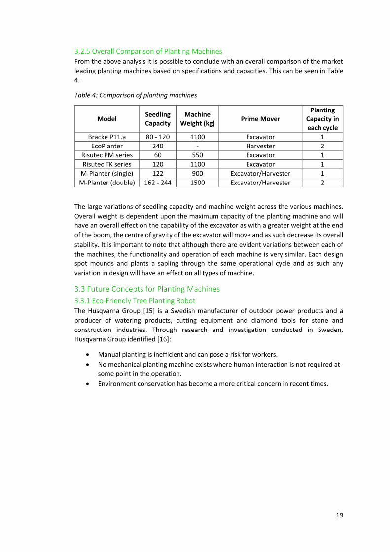
3.2.5 Overall Comparison of Planting Machines From the above analysis it is possible to conclude with an overall comparison of the market
leading planting machines based on specifications and capacities. This can be seen in Table
4.
Table 4: Comparison of planting machines
Model Seedling Capacity
Machine Weight (kg)
Prime Mover Planting
Capacity in each cycle
Bracke P11.a 80 - 120 1100 Excavator 1
EcoPlanter 240 - Harvester 2
Risutec PM series 60 550 Excavator 1
Risutec TK series 120 1100 Excavator 1
M-Planter (single) 122 900 Excavator/Harvester 1
M-Planter (double) 162 - 244 1500 Excavator/Harvester 2
The large variations of seedling capacity and machine weight across the various machines.
Overall weight is dependent upon the maximum capacity of the planting machine and will
have an overall effect on the capability of the excavator as with a greater weight at the end
of the boom, the centre of gravity of the excavator will move and as such decrease its overall
stability. It is important to note that although there are evident variations between each of
the machines, the functionality and operation of each machine is very similar. Each design
spot mounds and plants a sapling through the same operational cycle and as such any
variation in design will have an effect on all types of machine.
3.3 Future Concepts for Planting Machines
3.3.1 Eco-Friendly Tree Planting Robot The Husqvarna Group [15] is a Swedish manufacturer of outdoor power products and a
producer of watering products, cutting equipment and diamond tools for stone and
construction industries. Through research and investigation conducted in Sweden,
Husqvarna Group identified [16]:
Manual planting is inefficient and can pose a risk for workers.
No mechanical planting machine exists where human interaction is not required at
some point in the operation.
Environment conservation has become a more critical concern in recent times.

20
From these conclusions, industrial engineers at Husqvarna Group have designed an eco-
friendly tree planting robot of four-legged design equipped with an extending arm and
planting head. A CAD generated render can be seen in Figure 15.
This robot concept has the capacity to carry up to 320 saplings in a single load and to reduce
overall carbon footprint is steam powered [17]. Its small size facilitates efficiency and flexible
manoeuvring through tough terrains besides reducing the ground pressure exerted on the
forest floor. Saplings are fed into the machine at the front and loaded onto a revolving
cartridge. When empty, the robot is required to return to a stock location where it is refilled
and returned back to the planting site. Further renders can be seen in Figure 16 outlining the
basic operating principles of the sapling planting system.
As a prototype, this robot is still unavailable on the market however it is evident to see that
these future designs are still incorporating design principles of existing machines. As part of
this critical analysis, this concept provides an example of how machines may develop in the
future and gives an opportunity to identify design areas that may be incorporated into design
improvements of this project. However, from this concept, Husqvarna Group identified some
areas where advancements had been made:
It optimises its sapling storage by not leaving empty spaces in its skeleton.
Its four-legged shape allows planting in any kind of terrain.
It has some automated reloading process.
Figure 15: Eco-friendly tree planting
robot [15].
Figure 16: Sapling planting system [15].

21
3.3.2 Tree Planting Drone BioCarbon Engineering [18] is a UK company that has tackled the deforestation problem with
a future concept based on a different technology. This small engineering company have
developed a solution to major worldwide deforestation by re-planting on an industrial scale
using Unmanned Aerial Vehicles (UAV’s). The overall process involves gathering detailed
terrain data to produce a 3D map of the land. From this, the UAV is able to then carry out
precision planting activities and finally the land is monitored to provide assessments of the
ecosystem health [18]. Figure 17 shows a rendered illustration of the process of planting
using a UAV to drop capsules to the ground that then biodegrade and allow the seedling to
grow.
This method reduces the cost of traditional reforestation methods by 15% with the overall
aim to plant up to one billion trees a year with this technology. It is not possible at present
to provide any remarkable conclusions as the technology is still very elementary and requires
a lot of further research, well out with the scope of this project however it is important to
identify the various technologies using different approaches so as to be aware that one
solution is potentially not the best solution.
3.4 Forestry Machinery
3.4.1 Harvester A harvester is a piece of heavy machinery that is used to fell, cut to length, delimb and buck
trees. The harvester is made up of the vehicle, which is a custom design based on an
excavator, and then the harvester head. Harvester heads can be bought separately and
attached to any kind of excavator arm. The main manufactures of harvesters and harvester
heads are John Deere and Ponsse, John Deere being the principal provider in the UK and
Ireland. Harvesters are used on level and steep terrain to fell trees and also for thinning
operations [19]. Harvesters are built to be very robust and cope with many different types
of terrain. The vehicle can be wheeled, tracked or walking; to increase the manoeuvrability
between trees many of the modern harvesters are articulated. Harvesters range in size and
design, this allows them to be used in a number of different environments; smaller
harvesters are better suited for thinning or moving on a steeper gradient. Bigger vehicles are
more suitable for thicker trees that will put more strain on the engine of the vehicle [19]. The
development and use of these harvesters has made the forestry industry much safer and
more efficient. Instead of having men on the ground using chainsaws, they are inside the cab
of the harvester where trees cannot fall on them and they do not have to worry about
chainsaw related injuries. The harvesters make felling more efficient by cutting the tree
Figure 17: Illustration of tree planting drone showing
seedlings being dropped in caplets to the ground [18].

22
down, delimbing and cutting the tree to size. Another advantage of the harvesters is the
advanced operating systems. These are used to monitor the machine performance as well as
analysing the log dimensions and calculating how to cut it in order to gain the maximum
amount of product. These systems rely on a number of different sensors and measuring
systems found in the latest state of the art harvester heads.
3.4.2 Harvester Heads The harvester head is the main point of interest; harvester heads come in a range of shapes
and sizes and then can be used on many different types of machine [20]. An example of a
harvesting head and prime mover can be seen in Figure 18. They are the part of the machine
that does the felling, delimbing and cutting of the trees. The harvester head is powered by
hydraulics; there is a hydraulic control valve in the harvester head that redirects the hydraulic
fluid coming from the vehicle. The value is controlled by electrical signals sent from the
driver. The fact that the head has its own control value is part of the reason it is so universal,
as it only requires a hydraulic input and output line from the vehicle [21]. Although there are
a number of different heads, each one consists of the same vital components:
Chainsaw- this is a very powerful hydraulically powered chainsaw that is used to
cut the tree at the base and cut it to length.
Delimbing Knives- 2 or more curved knives that wrap around the trunk, the tree is
forced through them, cutting off the limbs.
Feed Rollers- at least 2 feed rollers that close around the tree to grip it and then
force it back and forward through the delimbing knives.
Diameter sensors- these are used to set the knives so that only limbs are being
removed.
Measuring wheel- used to measure the length of the trunk as the rollers feed the
tree through.
The harvester once again makes the forestry industry much safer as again the driver remains
in the cab of the harvester [20]. New harvester heads are constantly being developed to try
and optimise the process and each tree. New designs use up to 6 knives for delimbing and
up to 4 feed rollers to ensure that the tree is well gripped. New developments are also being
made in producing sensors to determine the density of the wood, and therefore optimise
the way it is processed to make the most of each tree. Harvester heads are becoming more
and more complicated and this causes problems when they malfunction or break down [21].
Given the remote locations where these are used it is difficult to get the engineers out to site
and even more difficult to replace parts in the adverse weather conditions.
Figure 18: John Deere harvesting equipment [19] [20].

23
3.4.3 Forwarders A forwarder is a vehicle that normally works in conjunction with a harvester (Figure 19). It is
designed to collect the logs felled by the harvester and take them to a designated area of the
site for collection. The forwarder picks up the logs, using a custom boom similar to that of an
excavator, and then drops them in the load area which is being pushed in front of vehicle,
the logs are then moved at a designated area on the site. Picking the trees up does limit the
size of the logs that can be moved by a forwarder but it can help save the soil on the site.
The logs are not being dragged around the site which affects the soil quality [22]. Like the
harvester the forwarders are articulated to help them manoeuvre around the site, they can
also operate on wheels or tracks (although most are wheeled vehicles). Forwarders again
increase the safety of the site as no one needs to be on the ground while the feeling and
recovery process is taking place on the site. Forwarders range in size from small to large; the
small forwarders have a typical load rating of 9-11 tonnes and these are best suited for
thinning operations as they are small and easy to manoeuvre, only available as a 6 wheel
vehicle. Medium forwarders have a load rating of 12-13 tonnes, these are the most versatile
as they can be used in thinning and final felling operations. Medium Forwarders are available
in 6 and 8 wheel configurations. The largest forwarders have a load rating of 15-19 tonnes
and our mostly used when the terrain is difficult and long distances must be travelled. They
are the most powerful forwarders meaning they can go places smaller forwarders cannot
manage, always an 8 wheel configuration. The 8 wheels spreads the increased load better
than 6 would, this helps prevent the vehicle becoming bogged down [22].
3.4.4 Skidders The alternatives to forwarders are known as skidders. These are large heavy duty vehicle that
is used to drag logs out of the forest this is known as skidding [23]. Skidders can be used
instead of or alongside forwarders when removing logs, skidders are capable of removing
much larger trees than forwarders. Typically, forwarders are tracked or four wheeled with a
large turbocharged diesel engine to provide the power. They have articulated steering, the
driver is protected from falling trees or broken cables by a steel cab. A skidder can also be
used to remove tree stumps and create an initial path for other equipment, known as a skid
path. One of the advantages of skidding is that the trees particles and seeds will cultivate the
soil as it is dragged through the forest. Disadvantages include the damage to the remaining
trees when thinning, as the logs are dragged against them removing bark etc. The skidder
can also do a lot of damage to the top soil, as it creates large furrows. These furrows will
affect the natural run off patterns in the forest and this increases the cost of rehabilitation
and reforestation [24]. There are two main types of skidder used.
Figure 19: John Deere forwarder [22].

24
3.4.5 Cable Skidders Cable skidders have a high power winch at the rear with large funnel-shaped metal guards
to protect the rear wheels [23]. An example can be seen in Figure 20. The winch/cable is
wrapped around the trees and holds them as the skidder drags them to the landing area of
the site. Cable skidders are becoming less popular because they are more labour intensive,
the operator is required to attach the cables or someone else has to. Allow the cable and
winch design is very useful when thinning and it is not possible to get a large vehicle close
enough to pick up a tree [24].
3.4.6 Grapple Skidders Grapple skidders are becoming more and more popular; they have a hydraulic grapple bucket
in place of a winch [24]. The bucket grabs and lifts the trees; the boom that attached the
grapple bucket to the skidder can be single function or dual function. A single function boom
has two hydraulic cylinders that allow movement in only one direction [23]. The dual function
boom has four cylinders attached to it and this allows movement in two different directions,
so as well as raising and lowering the grapple can be moved closer or further away from the
skidder [24]. A third kind of boom allows for sideways movement in addition to the dual
function booms movements.
3.4.7 Engcon Tiltrotator Attaching a machine to the hitch of a 360o excavator restricts motion to only the positions
that the excavator arm itself can reach. As a further attachment to increase manoeuvrability,
the Engcon Tiltrotator is an add-on adaptor that can be attached between the fixed hitch on
the excavator and the tool [25]. Through hydraulic actuation, motion of any attachment is
increased through many different degrees, allowing the ability for the tool to be operated
from a variety of different positions and ultimately increasing the precision and
manoeuvrability of the tool.
Figure 20: John Deere cable skidder [23].
Figure 21: Caterpillar grapple skidder [24].

25
Incorporating this attachment into the design of the tree planting machine would allow the
potential for advanced movements, especially on variable terrain where the position of the
excavator was critical. One of the design requirements throughout the project is that the
planting machine operate on steep and uneven terrain. With a tilt-rotating hitch, position of
the excavator becomes less critical as the moving head could compensate for any uneven
positioning. However, looking specifically at the EC15B tiltrotator (from 360 kg) and the
EC15B-R rotator (310 kg), weight is important [25] (Figure 22). By continuing to add a mass
to the extended arm of an excavator, the centre of gravity of the entire machine changes.
This is a particular issue on uneven terrain where the excavator relies upon its centre of
gravity existing around the turntable between the tracks and the body. Excavator
manufacturers outline the extremes to which their machines can operate and so it is
important that these weights are not exceeded. By continually adding equipment to the
digger arm, the maximum potential of the machines operational capabilities reduce.
3.4.8 Helac Powertilt Extending on rotating actuators, the Helac Powertilt provides a tilting action up to 180o full
range using a sliding spline shaft. This device has the ability to provide additional movement
to the excavator, ultimately increasing overall productivity by 50% [26]. The device is
powered by the hydraulic pump situated in the excavator with flow provided from lines
extending from the auxiliary circuit. With its relatively small size, the Powertilt is able to
provide rotational motion up to 180o around one axis converting linear piston motion into a
shaft rotation in the spline housing [26]. By only providing one additional rotation around
one axis, the overall weight of the device can be reduced, with the smaller size producing a
more compact attachment.
3.5 Hydraulics The role of hydraulics, in particular in this industry, was understood to be critical for power
transmission enabling easily amplified power to be controlled from simply a joystick. The
motion and functions associated with a 360° tracked excavator are all accomplished with the
utilisation of hydraulic fluids, as are many forestry attachments. As a subject not well
investigated through the academic curriculum thus far a short study was conducted.
3.5.1 Basic Principle The underlying principle of a hydraulic system is rather simple: force is transmitted from the
point where it is applied to another point via an incompressible fluid. More often than not
the force is multiplied through use of geometry variations. Hydraulic systems are capable of
transmitting high forces very quickly and accurately using relatively small pipes which can
(a) (b)
Figure 22: (a) Engcon Tiltrotator EC15B (b) Engcon
Rotator EC15B-B [25].

26
travel large distances and through awkward shapes. The principles of hydraulics were first
explained by Blaise Pascal when he stated:
“Pressure applied to any part of a contained fluid transmits to every other part with no loss.
The pressure acts with equal force on all equal areas of the confining walls and perpendicular
to the walls.” [27].
3.5.2 Hydraulic Pressure and Force Hydraulic pressure P, is the force F, exerted on a unit area A, of a material by a fluid and is
related as follows:
𝑃 =
𝐹
𝐴
(1)
Hydraulic power �̇�𝑚𝑎𝑥, is a function of the hydraulic pressure P, and the flow rate Q, of the
contained fluid:
�̇�𝑚𝑎𝑥 = 𝑃𝑄
(2)
3.5.3 Hydraulics within Excavators and Forestry Machinery Hydraulics are important in providing the power for many of a 360° tracked excavator’s
primary moving parts, such as the excavator’s boom. The use of three hydraulic rams along
the excavator’s boom gives the operator maximum control over the intricate motions
required of the boom. In many ways, the hydraulic rams act like the muscles in a human arm.
An illustration of this can be seen in Figure 23.
Not only are hydraulics utilised on the prime mover, the technology is also extensively used
in attachments located at the end of the excavator boom. Many of the forestry machines
and attachments mentioned previously use hydraulics to provide power. The Bracke P11.a
tree planting machine utilises hydraulics to provide the power required in the scarifying
blade, the delivery of the dibble to the ground and for the rotation of the carousel.
Hydraulics are common in forestry machinery due to their relative simplicity and the ease of
maintenance they afford when compared with other power sources such as electrical and
pneumatic. The utilisation of often small and flexible hosing for power transmission within a
hydraulic system enables transmission of power to difficult to reach locations such as the
end of the dipper on the excavator.
Figure 23: Hydraulic rams on excavator arm [58].

27
3.6 Industrial Contact
As part of continuous development for the project, it was suggested to the group by Mr
McArthur that meetings and visits be organised to develop a broader understanding of the
forestry industry and the machinery operated for harvesting and planting. It was also an
opportunity for the group to present ideas to industry experts and obtain feedback on where
further amendments could be made or where requirements were being met. The group had
a proactive attitude in trying develop a solution that would be effective in the industry.
A list of companies that were contacted and visited include:
Scot JCB
John Deere Forestry
Jas P Wilson Forest Machines
Clark Engineering
Forestry Commission Scotland office and planting site
Edinburgh Trams
ECM
BSW Timber Group
Dulnain Plant Hire/Christie Elite
A brief analysis of some visits made is covered below:
3.6.1 Scot JCB Meeting with Andrew Campbell allowed for a short discussion about the use of 360o tracked
excavators in forestry operations. With a vision to design a mechanical planting machine as
an attachment suitable for use on the excavator hitch, this discussion gave insight into how
to make this design requirement possible and the problems that may be faced. One of the
problems faced with implementing a tracked excavator in the forest is ensuring the machine
can operate on the soft and often uneven terrain. This is overcome by using low ground
pressure crawler tracks with a larger surface area to support the overall weight of the
machine. This is further outlined in section 4.3.3. For the purposes of the design project, a
JCB JS145 360o tracked excavator was selected as the prime mover for the new attachment
to be coupled to, with a universal attachment hitch as standard. Using a universal attachment
hitch would allow for various manufacturers and models of 360° tracked excavators to act as
the prime mover.
3.6.2 Forestry Commission Scotland Further to simply understanding the mechanics and power systems of a mechanical planter
and the machines used to operate them, a meeting was held with Bill Jones from the
technical development department at the Forestry Commission. This allowed the group to
develop a greater understanding of the ground terrain typical in forests and also the planting
techniques and protocols followed at the present time. From the main issues discussed
regarding current mechanical planting techniques, the most prominent were ensuring
adequate manoeuvrability, ensuring the machine was able to operate on a variety of terrains
and gradients and ensuring the sapling was planted in a rigid base with suitable compaction
so as to maximise survival rate. Further to this, questions were raised regarding the present
techniques used in planting in Scotland with a range of answers presented:

28
Across a typical hectare, approximately 2500 – 3500 saplings are planted with the
hope that after five years, at least 2500 will grow to mature trees for harvesting.
Gap left between newly planted saplings is approximately 1.5 – 2.5 metres to allow
for growth.
The preferred plant for Scotland is the Sitka Spruce, having a quick growth period
and typically harvested for timber production after 30 – 40 years.
The direction of the planted sapling’s roots is critical to its survival. Roots must face
downwards in the vertical direction and not be curled upwards.
The season during which saplings are planted is not critical, however the weather is.
In inclement weather, frost penetration and high winds can be detrimental to the
survival of a newly planted sapling.
3.6.3 John Deere Forestry As part of the final design of the new planting machine, a simulation will be made for training
purposes. To gain an understanding of how simulators operate in the forestry industry, a visit
was made to John Deere Forestry where the group met Jock McKie to discuss the advantages
of simulation for training and to also discuss the workings of forestry equipment (see section
3.4). The group were given the opportunity to use the simulator, at the same time getting a
feel for the controls of harvester and forwarder machines used for harvesting forest
plantations. Further to this, a tour was given of the site and the group allowed to view a
range of machines up close to understand their workings. Documents specific to John Deere
were distributed for further reading and to help develop a critical analysis specific to the
project.
3.6.4 BSW Timber Group Pursuing a further understanding into tree planting and the methods involved, a meeting
was organised with Mick Bottomley, head of timber buying at BSW Timber Group, Corpach.
Through an informative discussion, the group engaged in learning about the most effective
methods of tree planting and some issues still present with mechanical planting machines.
Of these issues, the most prominent included ensuring sufficient spacing between trees. This
is most effective if the pattern is regular to maximise planting capacity per hectare. Further,
a discussion was had about the mounding process and how this is critical to the survival of
the sapling compacted into the soil. Finally, the group were introduced to JPP and bare root
sapling cartridges, with bare rooting being cheaper and more suited to manual planting. After
the discussion the group were given a guided tour of the sawmill to see the full operation of
what happens to the tree once harvested.
3.6.5 Dulnain Plant Hire/Christie Elite Nurseries Concluding the major visits made for the purpose of the project, the group were invited to
Christie Elite Nurseries in Elgin where a short tour was given by nursery manager Brian
McCamon. This allowed the group to see all the different sapling varieties planted across the
UK and see them all at various stages in life. Important to note was the initial growing time
required before the saplings were developed enough for planting in the wild and the amount
of preparation carried out prior to travel to the various sites.
From here, an opportunity arose to view two Bracke P11.a planting machines (see section
3.2.1) in action at a local Forestry Commission site. Being able to see all the components in
the machine allowed the group to develop an understanding of how the sapling is dropped
from the carousel to the mound and compacted. However, from this it was observed that

29
the complexity of the hydraulic and electronic systems in the machine were out with the
capabilities of the group. Further designing these systems were out with the scope of the
project, what with the final outcome to develop a model for simulation, not manufacture.
This aside, it did present an opportunity in the project for developing a basic understanding
of the on board systems. The knowledge of both the operator and site manager was valuable
in understanding more about the workings of the most favoured planting machine in the
industry at the present time.
4.0 Design The design section of the project focussed on improving current mechanical planting devices
and the creation of 3D CAD models suitable for use in simulation, to aid with future training
of operators.
4.1 Identifying the Challenges The extensive critical analysis conducted enabled the group to develop a strong
understanding of the workings of existing forestry tree planting machinery, and the issues
these devices currently face. There was an agreement reached between the group and the
project clients that the Bracke P11.a was the current market leader and thus would be
utilised as the basis for design going forward. The recurring challenges faced by current tree
planting machinery devices were:
The limited sapling capacity, leading to frequent reloading stoppages.
Large reloading times, due to manual reloading process.
Overall productivity of mechanical planting, compared with manual planting.
Low quality of mound compaction, reducing overall high planting quality associated
with mechanical planting.
4.1.1 Product Design Specification (PDS) The requirements of a forestry tree planting machine were then formulated, through
numerous group meetings, into a formal Product Design Specification (PDS). A PDS was used
to ensure the quality of a design and ensure that the final product was fit for purpose. The
specification created defined requirements for areas including performance, environment
and weight amongst many others; and sets constraints which any subsequent designs
adhered to. Treating this presentation as a Stage Gate process, section 2.2, code two
amendments were recommended and incorporated, giving the finalised PDS as detailed in
Appendix A5.
The PDS was then used as the reference point as the group defined a number of key functions
required of any tree planting machine. The functions generated were:
Scarification of soil/planting environment
Storage on machine of saplings
Delivery method of saplings to reforestation site
Delivery of sapling to final planted position
Maintenance of machine verticality
Method of soil compaction after planting
Movement of prime mover

30
4.2 Morphological Chart Based on the functions derived in the PDS, a morphological chart was drawn up to allow
these functions to be investigated in more detail by the design team. Extensive reference
was made to existing machinery, considering all possible mechanisms for each function. The
final morphological chart can be seen in Appendix A6.
The project definition and design requirements both state that the design shall be attached
to a 360° tracked excavator, and thus it was decided that the movement of the prime mover
shall be constrained to intermittently advancing, or spot planting. Not only is this easier for
planting and the likely terrains, it also has great environmental advantages in only impacting
small amounts of the overall terrain.
The three options for maintaining machine verticality when planting were discussed at
length, and the group agreed that this challenge should be met with the incorporation of a
Helac PowerTilt into the design [28]. This was the simplest of the three options investigated
but was extremely effective in achieving verticality. It was also by far the lightest of the three
options considered. With weight being critical to the success of the planting design, this gave
greater freedom to other elements of the design.
From the generation of the morphological chart, the group investigated which functions
were reliant on one another and began to group the functions together into sections for
further design investigation. The first grouping for investigation was how the saplings were
stored on the machine coupled with how they are delivered to site. The second key grouping
of functions included the soil scarification, the delivery of the sapling into the ground and
the subsequent soil compaction.
4.3 Power Design
4.3.1 Soil Bulk Density and Weight One important consideration when mounding is considering the overall weight of soil being
moved as this will have an effect on the performance of the excavator and attachments.
When designing the scarifying blade, the minimum requirement of the blade was its
capability of creating a mound by overcoming the resistive force exerted by the soil as the
blade cut through. By considering the various soils conditions that the machine may be
required to operate in, it is possible to estimate the approximate mass of soil being mounded
in each operation based on the required volume of the mound. From there, the approximate
force that the machine is required to overcome based on the weight of the soil can be
calculated and therefore provide a basic analysis on the appropriateness of the machine and
attachments. Further to this, a factor was included to represent further contaminants in the
soil such as rocks and roots as in any environment, an ideal model would not represent the
real conditions.

31
Figure 24 [29] illustrates a range of typical soils that are suitable for planting in and allow
root growth. As the soil bulk density increases, so too does the overall mass of the mound
based on a constant mound volume. It is important to understand that the density of the soil
will constantly vary. For example, when the soil is mounded, it will become more aerated
and less compact, therefore reducing the bulk density however when the mound is
compacted with the sapling inserted, the bulk density will increase as the soil becomes more
compact. For this reason it is difficult to provide an accurate model of the properties of soil
during the mounding process and as such the best way to design components is based on a
worst case situation using a soil with the greatest mass.
𝑊𝑠 = 𝑚𝑠𝑔𝜇𝑠
𝑊𝑠 = 110 𝑥 9.81 𝑥 1.2
𝑊𝑠 = 1295 𝑁
(3)
From this it is possible to show that the minimum force required to overcome the weight of
the soil by the machine including any contaminants is approximately 1295 N. This will
therefore form a design constraint ensuring that components designed are capable of
overcoming this minimum force and is fit for service.
4.3.2 Machine Hydraulic Power Output and Breakout Force Most modern excavators are driven predominantly by hydraulic components with the diesel
engine in place to drive the hydraulic pumps. The hydraulic system in the JCB JS145 is made
up of two variable displacement axial piston pumps delivering a total maximum flow rate of
124 L/min each. These pumps are used to supply hydraulic fluid to the entire mechanical
system including the dipper, boom, drive motors and accessories which are supplied through
auxiliary circuit line. Focussing on the planting machine attachment for this project, the
auxiliary circuit is particularly important for providing a hydraulic flow to any attachments
and consists of one flow and one return line that extends directly from the auxiliary hydraulic
system. It is also important to note that the flow rate in the auxiliary circuit will directly
𝑀𝑎𝑠𝑠 = 𝐵𝑢𝑙𝑘 𝐷𝑒𝑛𝑠𝑖𝑡𝑦 𝑥 𝑉𝑜𝑙𝑢𝑚𝑒 𝑤ℎ𝑒𝑟𝑒 𝑉𝑜𝑙𝑢𝑚𝑒 𝑖𝑠 𝑣𝑜𝑙𝑢𝑚𝑒 𝑜𝑓 𝑚𝑜𝑢𝑛𝑑
= 0.25 𝑚2 𝑥 0.25 𝑚 = 0.0625 𝑚3
Figure 24: Plot of soil bulk density vs. mass.

32
influence flow to other components and have an effect on what further movements are
possible in the excavator.
From technical data provided by JCB it was possible to calculate the maximum power
provided by each of the hydraulic pumps using a simple equation relating pressure with flow
rate [30]:
𝑝𝑚𝑎𝑥 =
𝑃𝑄
Ƞ𝑡𝑜𝑡𝑎𝑙
𝑝𝑚𝑎𝑥 =(𝑃𝑥105) (
𝑄60000) (
11000)
Ƞ𝑡𝑜𝑡𝑎𝑙
𝑝𝑚𝑎𝑥 =𝑃𝑄
600 Ƞ𝑡𝑜𝑡𝑎𝑙
(4)
(5)
Where: P = 314 bar (maximum pressure available through relief valve)
Q = 124 L/min (maximum flow from axial pump)
Ƞtotal = 0.87 (average for axial hydraulic pumps)
𝑝𝑚𝑎𝑥 =
314 𝑥 124
600 𝑥 0.87
𝑝𝑚𝑎𝑥 = 74.59 𝑘𝑊
Another important consideration in excavator design is the breakout force that the machine
can exert as the bucket is moved through the soil. In the case of this design, the standard
equation to calculate this was used however the result was assumed very approximate in
that more technical data was required by the group which was unobtainable from
manufacturers meaning that the overall breakout force calculated was a lot more
elementary and a detailed analysis out with the possibilities of the group. It is possible to
note that from the technical data that was obtained from JCB, the maximum dipper breakout
force possible by a JS145 excavator was listed as 6589 kilogram-force or 64616 Newton’s
[31]. Breakout force FB is stated as [32]:
𝐹𝐵 =𝑃 𝑥 (
𝜋4) 𝑥 𝐷𝐵
2
𝐷𝐷 𝑥 (
𝐴 𝑥 𝐶
𝐵)
(6)
In order to obtain all the relevant dimensions required for this evaluation, a visit was made
to ScotJCB to briefly view a machine and measure critical distances between pins. Such
dimensions can be seen in Figure 25 [32].

33
Also assuming a maximum working pressure P from the relief valve equal to 314 bar with
an assumed dipper cylinder diameter DB equal to 40 mm [31].
𝐹𝐵 =31.4 𝑥 (
𝜋4
) 𝑥 402
1600 𝑥 (
890 𝑥 390
520)
𝐹𝐵 ≅ 16500 𝑁
This simplified approach provides an approximation and shows that the maximum breakout
force of the excavator is limited when operating with an attachment of similar dimensions
of a planting machine. The distance of the blade edge on the planting machine from the hitch
pin is the major limiting factor for the maximum breakout force of the machine. The
maximum breakout force as outlined by JCB suggests operation with a trenching bucket,
typically a lot smaller and with a lesser offset from the hitch.
Selecting the appropriate machine for a specific purpose is critical to the success of the
operation. During site visits made by the group, it was verified by industry experts, namely
Jas P Wilson and ScotJCB that the most appropriate, and common, machine size for use in
forestry operations ranged from 12 – 18 tons and so it was acceptable to suggest the JS145
(machine weight approximately 14.6 ton) to be suitable for this specific application.
4.3.3 Ground Pressure Also a critical consideration for selecting an appropriate size of machine is the ground
pressure. By increasing the size of machine based on lifting and breakout capacities, so also
does the overall weight of the machine increase. In the forest, hard dry soils often give way
to soft gley soils depending on the lay of the water table. For this reason, the operator must
consider a machine capable of providing low ground pressure for use across a wide range of
conditions. It is possible to calculate an approximate value of ground pressure for the prime
A
B
C
DD
Figure 25: Excavator dipper dimensions.
A = 890 mm
B = 520 mm
C = 390 mm
DD ≈ 1600 mm (approximate
length from pin to blade tip on
planting machine)

34
mover and attachment operating with a typical track shoe width however, the applicability
of the calculated value is site dependent and as such provides a means of reference only [33].
𝑃𝑔 =
𝑊𝐿
𝑅𝑡𝑟𝑎𝑐𝑘 𝑥 𝐿𝑡𝑟𝑎𝑐𝑘
(7)
Where mean static ground pressure, Pg is unknown, wheel load, WL combines the total mass
of the prime mover and planting machine (based on P11.a (see section 3.2.5), track shoe
width, Rtrack is the widest possible available from the manufacturer and the track level with
ground, Ltrack represents the track length that is resting on the ground.
Wheel load, WL = 14600 + 1100 = 15738 kg {Ref. [31]}
Track shoe width, Rtrack = 900 mm {Ref. [31]}
Track level on ground, Ltrack = 2865 mm {Ref. [31]}
𝑃𝑔 =
15738
0.9 𝑥 2.865
𝑃𝑔 = 6100 𝑘𝑔𝑚−2 = 0.61 𝑘𝑔𝑐𝑚−2 = 0.61 𝑏𝑎𝑟
The value of ground pressure found above is representative of an overall weight combining
the machine and the planting attachment with the widest track shoes available from the
manufacturer. Based on a technical note published by the forestry commission [34]
regarding mechanised forestry operations, this figure is representative of the typical range
of machine operating in similar conditions where the forestry commission estimated tracked
machines exerted 0.45-0.52 kgcm-2 [34] dependent upon track width. In some circumstances,
prime movers operating in the forest are equipped with custom tracks.
From the very beginning of the project, the group were made aware of the large differences
that can exist in the size of machine selected and so these basic calculations provided a basis
for what weight range to design the new planting attachment to with respect to the varying
conditions that may exist in forestry operations.
4.3.4 Hydraulic Circuit Ensuring that the excavator is capable of providing adequate power to any auxiliary
attachments requires an understanding of the components required to provide flow from
the pumps to the components that will provide motion to complete the task for which the
machine was designed for. For this design, gaining detailed information again proved difficult
and the group were forced to continue on with designing the device based on available
information. Such information included the basic flow and pressure requirements of the
similar Bracke P11.a planting machine and Helac Powertilt actuator. It can be assumed that
the operating conditions of these existing machines would be similar to those of the new
machine. It is also important to note that one requirement of this design outlined in the PDS
was that it would be capable of attaching to a wide variety of tracked machines, each with
varying power methods. These may include powering attachments from central, auxiliary or
diesel pumps all sized according to the machine size and capable of providing varying
magnitudes of flow and pressure. Another variable when considering what machine to attach
the planting machine is the time of operation. If a planting machine is to be attached to a
prime mover for full time planting operation then more capital will be invested into the

35
machine so as to optimise output. Similarly, a prime mover being implemented on a planting
operation for a short period of time will be fixed quickly for basic operation. These
considerations have a significant effect on the overall operation of the attachments and the
power that is available for operation. Under these circumstances, implementing a
fundamental design is very complex and not practical. For this reason, the design was created
more conceptually rather than creating a technical design. By focussing more on the
conceptual design, a visual representation of the basic set up would be created allowing for
a representative model to be created suitable for simulation.
From the obtainable manufacturer information, the required figures that would allow the
group to create a conceptual circuit, can be seen in Table 5 . It can be seen that the operating
pressure of the Powertilt component is greater than that of the Bracke P11.a. This is because
the overall force required by the Powertilt is dependent upon the attachment that is to be
rotated, while the Bracke P11.a only has to supply enough pressure to rotate the carousel
for planting and pivot the blade for mounding. Similarly, the required flow rate corresponds
to the number of hydraulic components in each device. In the Bracke P11.a, multiple
hydraulic cylinders are required for a variety of applications while on the Powertilt, flow is
only required for one rotational movement.
Table 5: Manufacturer data regarding operating pressure and flow rate
Bracke P11.a Helac Powertilt
Operating Pressure (bar) 125 200
Required Flow Rate (L/min) 100 20
Max. pressure and flow rate available from JCB JS145 is 314 bar and 124 L/min respectively
Designing the flow circuit proved difficult with a lack of detailed information however it was
possible to design conceptually for the potential worst case situation. From this it was
decided that components should be specified to the information available and in many
circumstances components may be over-sized. However, in a heavy industries design such
as this, components should be of the highest quality with no margin for safety concern and
as such there should be no compromise on design decisions that may jeopardise the life in
service of the machine.
One of the biggest difficulties in conceptualising a circuit was how the flow would be received
from the excavator to the leveller and planter machines. From section 4.3.2, it was
understood that the auxiliary line provided the flow however it was required that individual
control be available to the operator for controlling the leveller and planter. By installing only
one auxiliary flow and return kit, the flow would need to be divided and regulated based
upon the requirements of each device. Individual control of each machine would not be
possible here due to the splitting of the fluid using only one spool valve controller.

36
To try to overcome this issue, Hytec Hydraulic Engineering Ltd were contacted with a view
to obtaining a present method of providing individual control in excavator attachments. It
was brought the groups attention that the only conventional way to do so without
introducing complex remote control devices would be to install two auxiliary flow and return
kits to the prime mover. An example of this can be seen in Figure 26. This would mean that
any excavator using this equipment would require to be further specialised using third party
auxiliary equipment. By using this information, a simplified hydraulic circuit was created
using Hydraforce i-design 5.0 and can be seen in Figure 27.
In designing a circuit that requires two flow and return hydraulic lines, the number of prime
movers with the ability to operate both the planter and leveller effectively from the cab
reduces as the third party equipment is not installed at manufacture unless specifically
requested. It is possible to use Figure 27 to explain the basic control process for successful
operation of each component.
Powered by the excavator diesel engine, the hydraulic pump draws fluid from the
tank around the circuit.
Figure 26: Auxiliary flow outputs on
excavator dipper.
Figure 27: Conceptual auxiliary hydraulic circuit for planting machine and leveller.

37
The main pressure relief valve regulates the maximum flow pressure to the auxiliary
circuit. The JS145 has a pressure relief valve regulating the system to 314 bar.
With the introduction of two auxiliary kits, a flow divider is required to divide the
flow equally with other components further along the circuit acting to control the
flow rate and pressure.
Each hydraulic line is then connected to a three way spool valve (detailed design of
operation out with the scope of the project). It is important to note that both
components will not be required to operate at the same time and so when one spool
is open, the other will be closed, locking the fluid in that circuit and preventing
motion. This therefore then allows the divider to distribute the flow unevenly in each
circuit.
With an uneven distribution of flow depending on what spool valve is open, the flow
rate and pressure must then be regulated according to the requirements of each
machine.
o Planter circuit
Flow control valve limits to 100 L/min
Pressure relief valve limits to 125 bar
o Leveller circuit
Flow control valve limits to 20 L/min
Pressure relief valve limits to 200 bar
In the low pressure return line, it is appropriate to include a hydraulic filter so as to
minimise contamination from the different circuits back to the hydraulic tank. This
is a measure to maximise the life of the components,
Before emptying back into the fluid tank, the return flows are then combined from
the two auxiliary return lines.
Filters are required around the circuit to suitably safeguard the system from any contaminants and prolong the life of components. Connecting hoses vary depending on the location in the circuit. The high pressure flow line was sized to have a 19 mm inside diameter, equivalent to a Gates M3K hose, which would be substantial enough to carry flow at approximately 124 L/min and 225 bar. Beyond splitting the flow through the divider, it would be suitable to use hose with a 12 mm inside diameter, again equivalent to a Gates M3K hose so as to maintain the required pressure for operating both the actuator and the planter. M3K hose meets required standards ensuring suitability in high pressure applications and is flexible and easy to route to tight areas. One further benefit is that the hose is protected from collateral damage being braided with two layers of high tensile steel wire. A further critical consideration to design of hydraulic circuits is the implementation of high quality components. Operating under high pressure and flow conditions, failure risk must be minimised as far as possible to ensure safe working conditions for the operator. Quality of components will play a major role in minimising this risk and ensure life in service of the machine is extended.
It can be seen from Figure 27 that the planter and leveller are both represented in the circuit as single actuators. The leveller is a rotational actuator and as such only has one input and one output as represented by the circuit diagram with the required flow rate and pressure entering the chamber. As outlined in section 4.5.1 the leveller was incorporated with respect to existing solutions already on the market but sized accordingly with the enhanced planting machine design.

38
As previously described in section 3.6, when the group got the opportunity to view the
Bracke P11.a in action, it was discovered that the power systems encapsulated within the
machine were out with the ability of the group. Also, the scope of the project from the
beginning stated that the group would aim to enhance existing planting machinery. After
speaking with two operators, it was discovered that there were positive reviews on the
internal hydraulic system in the Bracke P11.a. This was with regard to the response time of
the cylinders and the accuracy of the computer control. From this it was decided, both as a
group and with Simultech that with limited project time, enhancements would continue to
be made to mechanical components to improve the overall hard process and not consider
the equivalent software processes beside the basic design of major hydraulic components.
4.4 Unchanged Components Further to identifying the challenges of design for the project, a series of components were
modelled for the purpose of the final design but remained unchanged. These components
were modelled following close resemblance to any drawings and documentation provided
to the group. By analysing the existing Bracke P11.a planting machine, it can be simply
represented by four main sections, namely the blade, dibble and casing, carousel and
external machine casing. For the purposes of the project, the dibble, casing and external
machine casing were all unchanged and modelled as per existing drawings. This decision was
based on the opinions of Mr McArthur and a result of the visit to see the Bracke P11.a in
operation where the operator was positive of the working of these components.
For the purposes of simulation, the full workings of the sapling planting system were not
required and as such, the dibble was simplified. The only requirements for simulation is that
the functions of the machine are available and the model can be animated. This simplification
was also a result of a lack of information available explaining how the centre dibble system
worked. When the group viewed the P11.a in operation it was not possible to fully dismantle
the planting machine on site and so only select components were visible. Figure 28 illustrates
the final model of the dibble mechanism alongside an orthographic projection outlined in
Appendix A7. The sapling is ejected from the carousel and dropped through the central tube
of the dibble. To insert the beak into the mound a hydraulic cylinder provides linear motion
downwards where a second cylinder is used to control the opening and closing of the beak.
When the beak is open, the sapling is inserted into the mound.

39
The second section unchanged in the model was the external machine casing. This was
modelled to represent the existing machine with amendments made to accommodate the
integration of each of the major sections. The casing was designed to protect the internal
systems from any sudden impact and also the weather. It was further identified that the
casing should also protect from dirt and grime during operation. Further, the external
machine casing was designed in accordance with the existing Bracke P11.a in terms of
material selection. It was identified that the machine casing was manufactured from a
medium strength steel with a protective paint finish to minimise the risk of corrosion. This
was reflected in the model with consideration of material choice, although not a critical
aspect of a model destined for simulation. A final model of the machine casing can be seen
in Figure 29 with a further orthographic projection available in Appendix A8.
4.4.1 Dibble cylinder Design This cylinder is enclosed within the dibble housing inside the main frame of the planting
machine. This therefore made designing this cylinder more complicated what with a lack of
detailed information available to the group. However, one constraint of this design was the
Figure 29: Final CAD rendering of the external
machine casing.
Figure 28: Final CAD rendering (a) dibble mechanism,
(b) dibble mechanism located within casing.
(a) (b)

40
overall size of the cylinder. The outside diameter of the cylinder was restricted to 50 mm
therefore suggesting that the piston head diameter would have to be 40 mm considering a
5 mm wall thickness. The force exerted by the cylinder in this casing was approximated by
considering the overall force it would have to overcome in punching a sapling into the
mound. This force was assumed to be equivalent to the weight of the mound as it was
observed that the dibble was not required to move soil in the mound but just exert a force
capable of breaking the mound surface to create a divot for the sapling. By considering the
bulk density of soil in section 4.3.1 the required force was assumed to be 1295 N.
𝑃𝑐2 =
𝑊𝑠
𝐴𝑐2
𝑃𝑐2 = 1295
𝜋4
𝑥 0.042
𝑃𝑐2 ≅ 1.03 𝑀𝑁/𝑚2 ≅ 10 𝑏𝑎𝑟
(8)
In the design of this cylinder, the stroke length was based upon the displacement of the
dibble to insert the sapling the required distance into the mound. By considering the
predicted size of the machine, the stroke length was selected to be 400 mm. A simple
schematic can be seen in Figure 30.
In a similar analysis, maximum buckling load was calculated to ensure the selected cylinder
was of a suitable size for operation. Again, the Euler buckling theory was used with similar
values as before however using a smaller cylinder, therefore piston rod diameter, d = 25 mm
and buckling length, L = 800 mm. Maximum force to avoid buckling is:
𝐹𝐿 =
𝐾
𝑆
(9)
𝐾 =
𝜋2𝐸𝐽
𝐿𝑐22
𝐽 =𝜋𝑑𝑐2
4
64
(10)
(11)
𝐹𝐿 =𝜋3𝐸𝐽𝑑𝑐2
4
64𝐿𝑐22 𝑆
𝐹𝐿 =
𝜋3 𝑥 200𝑥109 𝑥 0.0254
64 𝑥 0.82 𝑥 3.5
𝐹𝐿 ≅ 16900 𝑁
Stroke Length = 400 mm
50
mm
Figure 30: Dibble cylinder dimensions.

41
From this it is possible to identify that the approximate maximum buckling load on this
smaller cylinder is 16900 N, which is again much less than the expected load through the
cylinder. It can be assumed in this analysis that the cylinder is more than suitable for
operation with the main operation to pierce a hole in the mound to insert a sapling.
4.4.2 Universal Hitch Analysis Further to discovering the requirement for a universal hitch as a coupling point for any
attachments to a 360o excavator, one was modelled based upon an existing design used
frequently in forestry. This provided a mounting point for the computer simulation model
and was not enhanced through the detailed design phase in any way. An orthographic
projection of the universal hitch can be seen in Appendix A9. However, to ensure the hitch
would be adequate for use in attaching the planting machine to an excavator, a simple FEA
study was conducted to analyse the approximate maximum stress locations across the
component and ensure minimal deformation occurred as a result of the applied loading.
Using ANSYS Workbench, the component was meshed accordingly using a fine relevance and
small edge length to enhance the computational solution. Further, refinements were
focussed around the fixing pin holes where the hitch would be rigidly constrained and the
attachment mounts where loading would be applied. Fixed supports were introduced around
the fixing pin holes to represent where the hitch would be rigidly attached to the dipper
cylinder. A simplified load was applied around the attachment mount area to represent a
typical loading scenario considering maximum breakout force as provided by the excavator,
weight of the planting machine attached to the hitch and resistance force of moving the
required weight of soil (see section 4.3.1). A simple free body diagram can be seen in Figure
31.
Results of the computational analysis can be seen in Figure 32 illustrating the maximum
deformation and maximum principal Von-Mises stress as a result of the applied loading. It
was found that the component deformed a maximum of 0.239 millimetres, suggesting
negligible movement as a result of manufacturing from high tensile low carbon steel. Using
this material, the yield stress is typically ≈400 MPa and the component was found to have a
maximum stress of 243.8 MPa. Both maximum stress and deformation were identified to
occur around the front face of the attachment mound at a location of least material usage.
However, it is possible to note that the maximum stress identified in the hitch exists below
Figure 31: Free body diagram of hitch.
Breakout Force
18.2 kN
Machine Weight
1.1 kN
Soil Resistance
1.2 kN
Direction of motion
Hitch

42
the yield strength of the material and as such can be deemed safe for operational attachment
of the planting machine.
4.5 Design Improvement Focus
4.5.1 Hydraulic Leveller
4.5.1.1 Conceptual Design In the early stages of the project design, members of the group met with representatives at
ScotJCB to discuss what prime mover from the excavator range would be most suited to
forest operations. The JCB JS145 excavator was selected for its mid-range weight and ability
to perform a wide variety of tasks from the universal hitch located at the dipper. It is
important to note that JCB was selected to provide a basis for design and because a local
contact was available however the final design would allow for attachment to a wide range
of mid weight excavators available from varying manufacturers. Throughout these meetings,
the manoeuvrability of the attachment was discussed as it was outlined from the PDS that
the device would be required to operate on a variety of terrains and gradients and would
also be required to maintain verticality during planting. The problem presented to the group
was that all the required movements would not be available from the excavator itself and an
auxiliary rotating attachment would be required to provide further movements.
Figure 33 illustrates the rotations and movements available from the prime mover (shown in
green) and the rotation that is further required (shown in red), should the excavator have to
plant on a gradient and still maintain verticality. From the critical analysis, two potential
options were outlined, namely the Engcon Tiltrotator [36] and the Helac Powertilt [28].
Comparing the mechanisms and movements of both devices, and further identifying the
additional rotations required, it was soon apparent that although a very versatile device, the
Figure 32: (a) Total deformation and (b) Von-Mises equivalent stress.
(a) (b
)
Figure 33: Excavator rotations.

43
Tiltrotator was over specified for the requirements of the planting machine. Further to this,
the Tiltrotator was also able to rotate any further attachments, however when planting,
orientation of the sapling being inserted into the ground was irrelevant. Table 6 outlines the
specs of the two devices for comparison.
Table 6: Leveller specifications
Engcon Tiltrotator EC15B Helac Powertilt PT10
Weight (kg) 360+ 385
Tilt Range (degrees) 80 134
Flow Rate (L/min) 80 20
Overall, by considering the requirements of the levelling device, the Powertilt provides the
required motion along one axis at a fraction of the power requirements of the Tiltrotator.
From section 3.4.8 the Powertilt is also a lot smaller than the Tiltrotator meaning that it will
be more easily integrated into the final design of the planting machine. This is an area where
the group were able to conceptualise the requirements of the planting device, investigate
the products existing in the market and design according to this, meaning time could be
distributed to focus on more involved components requiring further design.
4.5.1.2 Detailed Design Following on from the conceptual design of the leveller device, it was decided after
investigation that with a device performing very effectively in the market at present that
incorporating an existing component into the detailed design phase would prove more
effective than designing a similar component from the beginning.
After considering the advantages and disadvantages of two existing leveller devices on the
market, the most effective design for implementation was the Helac Powertilt due to its
simple functionality, low weight and ability to actuate rotational motion over a larger angular
range. After contacting Helac Inc. for more information, it was discovered that a lot of
detailed information would not be available to the group for concern of infringing IP rights.
However, as the scope of the project was to identify enhancements for existing planting
machines, the group were able to conceptually design the leveller device based on
information and develop a model based on basic dimensions and exploded drawings that
were available on the public domain. These documents can be seen in Figure 34.
Figure 34: (a) Orthographic projection of leveller, (b) Exploded assembly of
leveller [26].
(a)
(b)

44
It is important to note that for the purpose of modelling and with respect to the time
constraint on the group for the project that the actuator was simplified but still designed so
as to perform the required operation for the purposes of a proposed simulation model. With
limited dimensions, the device was designed around the top housing with solid steel bars
mounted in place of the pin holes. This was incorporated into the design so as to meet the
criteria of attaching directly on to the universal hitch with little interaction from the
excavator operator. The final modelled component can be seen in Figure 35 with a full
dimension drawing available in Appendix A10.
4.5.2 Scarifying Blade
4.5.2.1 Conceptual Design The scarify blade is the component that makes first contact with the ground in the planting
process. Its primary function is to prepare a mound of soil suitable for a sapling to be planted
in. Second to this, the blade also acts as a compaction mechanism to ensure the sapling is
secure in the mound. The potential challenges that the group identified after meeting with
representatives in industry were that existing machines had no way of quantifying that the
required mound volume was approximately uniform every time. It was identified that some
existing machines were better at aerating and compacting the soil than others. As with any
other existing designs, it was required that the blade should be strong and stiff and be able
to overcome shock loading from roots and rock below the surface.
The sub-team looked to identify where possible improvements could be made to the most
common existing design, namely the Bracke P11.a and sketched a number of possible
concepts to be put forward for analysis and discussion. The most promising concepts
selected for the blade design can be seen in Figure 36.
Figure 35: Final CAD rendering of
hydraulic leveller.

45
It can be seen that a wide range of possible concepts were harnessed from the morphological
chart and each try to consider the criteria of the PDS in a different way. Such examples from
above include applying spill guards (4) to the blade to control the mound volume, using a
rotating auger (3) to help with soil aeration. Design (5) considers the actions of the existing
P11.a and simplifies the design to a flat plate controlled by two linear displacement cylinders.
From these concepts, a Controlled Convergence Matrix (CCM) technique was used from
Stuart Pugh’s Total Design [37]. This is an iterative concept selection technique where
different designs are compared against a datum design and rated with respect to chosen
criteria. Criteria was chosen based upon its applicability from the PDS. An example of one of
the iterations carried out can be seen in Table 7.
(2)
(4)
(7)
(6)
(1) (3)
(7)
(5)
Figure 36: Scarifying blade conceptual designs.

46
Along with further iterations, each time changing the datum, concept seven was a continued
success following on similarly from the existing design of the P11.a but incorporating a
hollow volume to help ensure the approximate target mound volume was achieved during
every planting cycle. Further, the design also employs a serrated tooth edge along the leading
edge to help achieve better aeration when the soil is being mounded as well as break the
surface easier in colder climates when the ground is harder.
4.5.2.2 Detailed Design Progressing to the detailed design phase for the blade design, the final solution from the
CCM was carried forward for detailed design to ensure it would be fit for purpose in
operation. From the conceptual design, criteria to focus on while finalising the design
included:
Ensuring structural rigidity was not compromised.
Considering wear resistance to extend life in service.
Ensuring the appropriate mound dimensions were formed while in operation.
Considering aeration when mounding and compaction when inserting the sapling
into the soil.
Figure 37: Final blade designs for detailed design.
1 2 3 4 5 6 7
Operation on variable terrain s - s s - s
Capability of creating mounds with specific dimensions (20-30cm high and 0.25m2). s - + - - +
Operation in adverse weather conditions D s s s s s s
Corrosion resistance s s s s s s
Operation in various soil conditions A + - + + - +
Resistivity to shock loading s - s + - s
T s s s s s s
Consideration of compaction and soil aeration + + + + - +
Access to components U s - s s - s
Ease of Maintenance - - - s - s
Ergonomic design M s s + - - +
Ease of operation - - - - - s
Life in service s s s s s s
Number of parts + - - - - s
Ability to perform localised scarification + + + s s +
Resistivity to temperature extremities s s s s s s
Weight + - - + - +
Response time - s - - - s
4 1 5 4 0 6
4 9 5 5 12 0
10 7 8 9 6 12
0 -8 0 -1 -12 6
CRITERIACONCEPTS
CONTROLLED CONVERGENE MATRIX: SCARIFYING BLADE
Operation in dirty environment
Sum of +
Sum of -
Sum of s
Score
Table 7: Controlled convergence matrix for scarifying blade
Controlled Convergence Matrix: Scarifying Blade

47
Figure 37 illustrates the final solution that was developed as an enhancement to existing
designs. It can be seen that the new design follows existing operational principles with the
extension of the hydraulic cylinder to protrude the cutting edge and maximise penetration
depth with the least force. The biggest design difference extends from the criteria outlined
in the PDS stating that from Forestry Commission literature [5] a specific mound size and
volume are favoured. This is to try to optimise the number of saplings planted over the entire
land area and also help to ensure that sufficient soil surrounds the sapling root area to ensure
suitable stability and maximise survival rate.
Taking forward sketches from the conceptual design phase, the final design was created on
Autodesk Inventor 2016. This can be seen in Figure 38 with a detailed drawing outlining all
major dimensions in Appendix A11.
From Figure 38 it can be seen that the optimised design is based loosely on existing shapes
from similar planting machines. Throughout the critical analysis phase, where different
machines were investigated, it was identified that the profile of the blade has very minimal
variation across the different manufacturers. From this, the sub-group focussing on blade
design decided to focus on enhancing the component using a similar profile as it was
recognised from existing machines to be acceptable in operation.
The critical enhancement introduced into the blade was the hollow internal volume designed
in line with following the mound size requirements. The prismatic trapezoidal volume of the
blade was integrated into the design to both act as a gauge corresponding to the correct
volume of mound required but also to better direct the soil while being inverted. One further
design enhancement was derived from existing soil aeration machines. Figure 38 illustrates
a series of protruding teeth across the primary mounding edge of the blade face. This was
incorporated in to the design as a means of better aerating the soil during the mounding
process so as to provide a better growing environment for the sapling once inserted into the
ground. Similar to the design of earth moving buckets, teeth also provide a means of stability
should the excavator be operating on a gradient and so this was established into this design
also as a precautionary safety feature should the excavator require to be stabilised.
Figure 38: Final CAD rendering of scarifying blade.

48
Compaction Test
Further to identifying the final design of the scarifying blade to be that of the hollow volume
design, a simple experiment was set up to compare the compaction qualities of this
enhanced design against the existing design implemented on the Bracke P11.a. The
experiment was designed to illustrate basic soil compaction qualities of each design so as to
draw a conclusion on the effectiveness of the new design. An illustration of the experimental
setup can be seen in Figure 39. Two blade profiles were manufactured by 3D printing to 1:10
scale. By measuring the approximate displacement of each blade after applying a specified
load, compaction characteristics of each design could be identified and compared across the
two designs.
A specified volume of soil was formed using a 3D printed capsule that was designed to the
required mound dimensions, Vs = 0.0625 m3, approximate Wc = 0.037 kg, before being
mounded into the experimental container. This volume and weight were kept constant
throughout the experiment. Stability rods were fixed to the base of the container and
positioned so as to insert around all four corners of each blade profile. This ensured that the
orientation of the profile was the same throughout each test. From the mound datum, the
initial height of the mound was measured for each test and an applied load of 1 kg exerted
onto the blade profile to create a compaction force on the soil. The final height of the mound
was then measured and the absolute displacement of the blade profile calculated. This test
was conducted five times for the two blade profiles so as to minimise experimental error and
draw a more affirmed conclusion.
The results of this experiment can be seen in Figure 40. It can be seen that across the five
tests, there was very little significant variance in the displacement between the two blade
profiles. This may not be the case at full scale however as these models were printed to a
reduced scale it may have had a result on the overall compaction capabilities of each design.
Although these results do not show a significant variation in the overall compacted
displacement for each design, it was evident to see that after each compaction test, the
enhanced design had produced a more refined mound than that of the Bracke equivalent.
This observation is important as it outlines that the refined design was more capable of
producing a mound of similar compaction quality but with a more defined mound shape.
Figure 39: Experimental setup for compaction testing.
Stability Rods
Soil
Container
Approximate
required soil
volume
V = 0.0625 m3
Blade Profile
Applied Load Fc = 1kg
Alternative Profile
Mound Datum

49
From an early stage in the project, it was outlined to the group by the Forestry Commission
that the shape and size of the mound was critical to the survival of a sapling. Having a more
defined, protruding mound provides a more stable base for the sapling so as to be protected
from the weather. From this small experiment, it can be concluded that the enhanced design
performs with similar capabilities to that of the existing machine in terms of mound
compaction displacement. This is understandable as the two blade profile are very similar
however by adding the hollow volume section, each mound becomes more refined as the
blade acts to control the volume of soil and as such prevent the mound from collapsing as
the sapling is inserted.
By basing the design analysis for the blade around information available from Caterpillar [38]
it is possible to identify the typical conditions expected to be operated in by the blade
creating a mound. This can be seen in Figure 41.
1 2 3 4 5
Figure 40: Plot of blade displacement during testing for various profiles.
Figure 41: Soil conditions vs. bucket design [38].

50
It can be identified that the blade will be required to operate in conditions similar to those
of general duty (GD) and heavy duty (HD) buckets on excavators. This provides a basis for
design by suggesting that the blade should be able to withstand a suitable degree of shock
loading and be further resistant to wear than other components. After making a site visit to
view the existing Bracke planting machine, it was identified that all components classified as
operating under high loads had been manufactured using 10 mm steel plate including any
reinforcing bracings across the blade and mounting points. It is important to design for wear
resistance and to minimise the amount of bending taking place in operation. One design
technique employed here was designing to existing conditions. By identifying the existing
thickness of the blade plate, it was assumed that this same thickness could be employed in
the enhanced design as it was identified that the new blade profile would be operating under
very similar conditions.
Important of the design of the blade was ensuring the position of the hydraulic ram was
suitable to ensure effective operation and minimised risk of failure under high loading forces
when mounding. From the visit made to Christie Elite Nurseries to see the Bracke P11.a in
action, it was identified that the greatest loading conditions on the blade occurred during
mounding. For this reason, an FEA analysis was conducted to investigate the most effective
position for the hydraulic cylinders to be mounted. Two designs were analysed and can be
seen in Figure 42. Design consideration (1) suggests mounting the cylinder pin close to the
blade edge so that in the mounding position the cylinder is fully extended, retracting once
the mounding cycle is complete ready for compaction. Design consideration (2) suggests
mounting the pivot pin at a greater distance from the blade edge. At this position, the
cylinder is fully retracted when mounding then extending for compaction.
This analysis was developed to investigate equivalent stresses that occurred in the piston rod
at two different positions after loading during mounding. It is important that stress in
components is kept to a minimum, not exceeding maximum yield strength at any point
during operation. Also critical to consider is potential impact loading that may occur in
operation. When this occurs, stresses in machine components will be much higher but only
applied over a short period of time. These stresses are difficult to predict however, ensuring
maximum stress occurring through static loading is maintained well below yield ensures a
safety factor for sudden stress fluctuations.
(a) (b)
Figure 42: (a) Cylinder fully extended during mounding process
(Design consideration (1)), (b) Cylinder fully retracted during
mounding process (Design consideration (2)).

51
Using ANSYS Workbench, the component was meshed accordingly using a fine relevance and
small edge length to enhance the computational solution. Further, refinements were
focussed around the pivot pin holes and the piston rod. For each design consideration,
support constraints and load conditions were identical, where fixed supports were applied
around the pivot pin holes and loading was applied around the piston rod. Applied loads
were simplified to consider only excavator break out force and soil resistance in the z-
direction. In the y-direction, the approximate weight of the mounding blade component was
also considered. A schematic of these loading conditions can be seen in Figure 43.
Although a relatively simple analysis, the results provided a means of confirmation of a
design consideration important to the success of operation of various critical machine
components. The results of the two design considerations can be seen in Figure 44. From
these plots it can be observed that large stress variations exist depending on the position of
the piston rod under the same loading conditions. As has been identified, it is critical to
ensure a low stress magnitude across all machine components. Although it can be seen that
the maximum stress magnitude of the two analyses is 332 MPa, which is lower than the
material yield strength, it is important to consider a generous safety factor in case of impact
loading.
It can be concluded that design consideration (2) is a more appropriate concept and follows
a similar operating principle to the Bracke P11.a. By applying the greatest load to the cylinder
in the retracted position, the rod is more constrained within the cylinder bore and as such
has a greater resistance to deformation under loading. Another benefit of conducting the
Figure 44: Plot of equivalent stress, (a) cylinder fully extended and (b) cylinder fully
retracted.
Figure 43: Free body diagram of cylinder with applied forces.
Breakout force 18.2 kN
Blade weight ≈ 250N
Soil resistance 1.2 kN

52
mounding process in the retracted position minimises the risk of contamination on the piston
rod. When mounding takes place, the soil is being moved and as such creates a potential for
debris to stick to machine components. In order for operation to be as smooth as possible,
contamination risk must be negligible and as such conducting the dirtiest operation in the
retracted position further reduces this risk.
4.5.2.3 Blade Cylinders Design This cylinder requires to overcome the resistance of the soil as a mound is created and as
such is the largest cylinder on the machine. Two cylinders were designed to operate to
provide the actuated motion and also reduce the overall load on each cylinder. An important
consideration in this design is the occurrence of compression loading on the piston rod.
When mounding the soil, a compression force will be induced on each rod and as such, each
cylinder should be designed in accordance to this, over-sizing if necessary to ensure risk of
failure is minimised. For the purpose of this design, the cylinder was sized in accordance to
the equivalent Bracke machine, knowing the approximate diameter of the piston head (80
mm) and assuming the cylinder to have to overcome the overall breakout force provided by
the machine (16500 N). This then allowed for an approximation of the required supply
pressure of the cylinder to be found.
𝑃𝑐1 =
𝐹𝐵
𝐴𝑐1
𝑃𝑐1 = 16500
𝜋4
𝑥 0.082
𝑃𝑐1 = 3.28 𝑀𝑁/𝑚2 ≅ 33 𝑏𝑎𝑟
(12)
By designing to the specifications as outlined by the equivalent Bracke P11.a, it suggests that
the cylinder will be more than suitable for the application and also considering the action of
two cylinders operating to provide the same movement. Another important consideration in
designing this cylinder is the stroke length of the piston rod. For the purpose of this design,
the stroke length was designed to be 505 mm. A simple schematic can be seen in Figure 45.
By identifying the approximate working pressure of the cylinder it is also important to
consider the piston rod diameter and ensure it is suitable for use in operation in terms of
being able to operate without buckling. The Euler buckling theory can be used to calculate
the maximum bearable force to avoid buckling [35]. Critical dimensions of this analysis
include piston rod diameter, dc1 = 40 mm, buckling length, Lc1 = 1010 mm, Young’s modulus
of steel, E = 200 GPa, factor of safety, S = 3.5. Further expressions used also include buckling
load, K and inertia of the rod cross section, J. Maximum force to avoid buckling is:
𝐹𝐿 =
𝐾
𝑆
(13)
Stroke Length = 505 mm
80
mm
Figure 45: Blade cylinder dimensions.

53
𝐾 =
𝜋2𝐸𝐽
𝐿𝑐12
𝐽 =𝜋𝑑𝑐1
4
64
(14)
(15)
𝐹𝐿 =𝜋3𝐸𝐽𝑑𝑐1
4
64𝐿𝑐12 𝑆
𝐹𝐿 =
𝜋3 𝑥 200𝑥109 𝑥 0.044
64 𝑥 1.012 𝑥 3.5
𝐹𝐿 ≅ 69500 𝑁
It can be seen from the solution that the approximate maximum load to prevent buckling is
69500 N, which closely resembles the maximum breakout force that can be applied by the
excavator without any attachments. However, it has been identified that the maximum
breakout force as a result of the planting attachment is much lower than this and as such it
can be concluded that the cylinders used to pivot the blade are suitable for operation. It is
important to note that the cylinders were designed predominantly to ensure a suitable
stroke length was available alongside an adequate force. As such, in other aspects of the
design the cylinders appear oversized but this ensures a further factor of safety.
4.5.2.4 Material Selection Throughout the design phase for any industrial application, appropriate materials must be
selected for manufacture based on a wide range of properties and conditions that need to
be met in order for the component to be successful in the operating environment. Referring
back to the PDS developed earlier in the project, see section 4.1.1, a number of criteria were
outlined relating to material choice for the design of the blade, and where materials selected
must be:
Corrosion resistant.
Resistant to impact loading.
Resistant to scratching and denting.
Operable across a wide temperature range.
Lightweight as far as possible, at the same time not compromising strength and
rigidity.
Malleable and formable for standard manufacturing processes.
Readily available so as to reduce cost.
From the criteria outlined above, material choice is overall limited as it is important that the
final design strives to meet all criteria. However, in the design of the blade, compromise is
required. An example of this may include selecting a high strength, lightweight composite
material such as a glass or carbon composite which would be ideal in a lot of applications
however on the contrary to this, composite materials of this form require more complex
manufacturing processes and are available only at a premium cost, therefore making metals
a more favourable choice.

54
To aid the selection process for material design of the blade, and similarly other components,
the CES Edupack database was used, helping to rank materials in an order with respect to
the selected criteria. The first stage of selcting materials in a design analysis always involves
outlining the properties of all possible materials in terms of two major criteria. This allows
for an Ashby diagram to be developed allowing for a visual inspection of the basic suitability
of materials. The plot was developed with density against Young’s modulus. This can be seen
in Figure 46.
From Figure 46 it is possible to see visually that some materials are a lot more flexible and
lighter than others. A simple inspection allows the designer to eliminate unsuitable materials
and focus on the most appropriate material families. Another look at the criteria from the
PDS yields the most appropriate materials to be composites and metals. Polymers would be
suitable for some applications however in heavy machinery design stiffness and rigidity is
vital under various loads in different environments. On the other hand, ceramics are a very
stiff but brittle material that perform well in compression, however one of the criteria states
the machine must be able to overcome impact loading and so this this material would again
be unsuitable.
Figure 47 makes a comparison between metals and composites by considering Young’s
modulus against approximate price per kilogram. This is a good comparison as it shows that
although the relative stiffness of the two types of materials are approximately the same,
there is an order of magnitude difference in the price between conventional metals and more
complex composites.
Investigating select materials further, carbon fibre and glass fibre reinforced composites
CFRP and GFRP respectively are modern materials developed by laminating a series of layers
of continuous fibres all bonded in an epoxy matrix. With a very high strength and stiffness,
they are favourable in high strength applications and are capable of withstanding shock
loading however, the manufacture process is very labour intensive and therefore more
expensive. Manufacturing a component from composites is very complex as joining presents
Density (kg/m^3)100 1000 10000
Yo
un
g's
mo
du
lus (
GP
a)
0.001
0.01
0.1
1
10
100
1000
Non-technical ceramics
Technical ceramics
Polymers
Composites
Metals and alloys
Elastomers
Natural materials
Foams
Figure 46: Density vs. Young's modulus for all common materials.

55
an opportunity for significant stress concentrations and any holes cut into the material
reduces the failure strength.
Identifying the various metals available, there is a very wide price range for a relatively
uniform stiffness. To optimise the cost of manufacture and not compromise on strength and
stiffness, carbon steel would be an appropriate choice as seen from Figure 47. By increasing
the carbon content in the metal, the designer can optimise the surface treatments applied
to the steel. A further advantage of using metals over composites is that composite materials
are affected by moisture, heat effects and fatigue loading. Surface treating a more complex
material like CFRP would considerably increase costs beyond need for an industrial machine
therefore again making carbon steels more favourable in this particular design.
From information provided from brochures from manufacturers of heavy equipment, the
material of choice is high strength carbon steel. One potentially detrimental concern of using
this material is the effects of corrosion. In the varying environment that this planting machine
will be required to operate in, moisture and temperature fluctuations will all affect the
material in such ways to cause rusting or affect the machine structurally. Therefore, it is
important in the design phase of the machine to consider how the materials used in design
would be surface treated to maximise its life in service. Common methods that would
present the best protection at the cheapest price may include galvanising or applying a hot
metal flame coating, the latter having less effect on surface distortion of the metal. To finally
finish off the component ready for assembly, a paint coating could be applied to create a
further protection layer and to aid aesthetic appeal.
From this it is possible to conclude that the most suitable material for the blade design is
high strength carbon steel. With a wide range of options for prior heat treatment processes
before entering service provides an opportunity to ensure the material is well equipped for
use in a varying environment at a cost effective price. It is also possible to conclude that
although various materials meet all the criteria of the PDS, the high strength steel does so at
a fraction of the price, and at a greater availability.
Price (GBP/kg)0.1 1 10 100 1000 10000
Yo
un
g's
mo
du
lus (
GP
a)
0.001
0.01
0.1
1
10
100
1000
GFRP, epoxy matrix (isotropic)
Cast Al-alloys
Aluminum/Silicon carbide composite
CFRP, epoxy matrix (isotropic)Stainless steelLow carbon steel
High carbon steel
Cast iron, gray
Metals and alloys Composites
Figure 47: Plot of Price vs. Young's modulus for metals, alloys and composites

56
4.5.3 Sapling Reloading Current sapling loading processes were found to be time-consuming due to the piecewise
nature of loading [39]. That is to say, loading sapling-by-sapling. It has been estimated that
modern planting machines occupy 15-20% of productive working time in a non-operative
position as the operator manually loads the carousel with saplings [40] [41]. Whilst in the
non-operative position, the machine’s capital costs and operator’s wage are still present
while production of the machine is zero [42].
On a site visit to view a Bracke mechanical planting machine, the project group observed a
reloading cycle completed by an experienced operator. It was noted that it took the operator
2 minutes 52 seconds to completely reload the Bracke’s carousel. When averaged over the
70 saplings reloaded in each cycle this equated to roughly 2.46 seconds per sapling. Over a
typical ten hour shift when operators are expected to plant as many as 1200 saplings this
resulted in a total reloading time of 50 minutes, 8.2% of the productive working time of the
machine. It was noted that time was small compared with those from literature and
highlighted the importance of an operator with good experience to the performance output
from mechanised tree planting.
4.5.3.1 Existing Concepts Existing Carousels (Piecewise)
The piecewise loading utilised by modern planting machine is a low-tech and robust method
which enables a degree of flexibility to planting operations. The low-tech nature of the
devices ensure maximum machine availability by reducing the number of components which
can possibly break down. Study found that there were two most common types of piecewise
loaded carousels used in mechanised tree planting: rotary carousels and linked-cassette
carousels. Examples of each type are given below.
Rotary Carousels: The two most common mechanised planting machines in use today, Bracke
P11.a and Risutec, both utilise a piecewise loaded, rotary controlled carousel. Examples of
these carousels can be seen in Figure 48. The Bracke carousel is composed of 72 cassettes
arranged in two concentric circular arrangements, offset such that only one circle presents a
sapling to the planting tube at any given time. The required rotary movement is applied to
the carousel by a hydraulic ram connected to a feeding head. On the other hand, the Risutec
device consists of 120 cassettes in three concentric circles. However, this carousel is only
suitable for smaller saplings.

57
Linked-Cassette Carousels: This type of carousel is evident on both the M-Planter and the
EcoPlanter devices. Examples of which can be seen in Figure 49. It operates by having all the
cassettes connected or banded together and using smaller rotational parts to create
connected motion through all of the cassettes, again to feed a single location leading to the
planting tube. The EcoPlanter device has the largest capacity of all current planting machines,
holding 200 saplings [43], but these saplings must serve two planting heads. In comparison,
each planting head of the M-Planter is served by a storage capacity of 122 saplings [44].
Process
Not only concerned with reducing the manual reloading time, the group investigated the
whole process of a sapling’s journey from germination through to planting into final location
by machine. It was hoped that other areas or components of the process could also be made
more efficient and thus increase the profitability of mechanised tree planting. First, the
existing process had to be understood. Using a piecewise loaded carousel, such as the Bracke
P11.a, the process can be seen in Figure 50.
Figure 48: Rotary Carousels: (a) Bracke P11.a [10] (b) Operator manually loading
Bracke P11.a carousel [10] (c) Risutec carousel [12].
Figure 49: Linked-Cassette Carousels: (a) EcoPlanter (b) EcoPlanter Carousel [57]
(c) M-Planter [6].
Figure 50: Original process associated with the Bracke P11.a.

58
Each of the other carousel concepts was considered with the entire process in mind and this
was a key criteria in choosing a final concept going forward.
Other Carousel Concepts
Tray-wise Loading Systems
Tray-wise loading is the process of reloading a mechanical planter with a full tray of saplings
[45]. Tray-wise loading greatly reduces the downtime of the machine and removes the
number of steps that must be performed manually. There are two concepts that have
currently been developed using tray-wise loading.
Mag-Mat: The Mag-Mat is a concept developed by students from Sweden. It is an
improvement on the current carousel system employed by the Bracke P11a. The current
carousel has a maximum capacity of 72 saplings. The carousel has to be reloaded by hand
once empty therefore 15%-20% of productive working time is spent reloading. The aim of
the Mag-Mat is to improve the efficiency of the Bracke planter by reducing the downtime of
the machine, and increasing the capacity of the carousel. The final design of the Mag-Mat,
which has been manufactured into a fully functioning prototype, can hold 320 seedlings. The
320 seedlings are loaded onto the Mag-Mat carousel in their cultivation trays, 8 trays in total
are loaded with each one holding 40 saplings. The Mag-Mat then removes the saplings one
by one. The only time planting needs to be stopped is when all 8 trays are empty and must
be reloaded. These improvements greatly reduce the down time of the machine during
planting and minimise the manual reloading required from the operator [39].
The Mag-Mat (Figure 51(a)) operates by selecting a full individual tray of saplings and raising
it up, then a hydraulic de-plugger is utilised to push each sapling out of the tray one at a time.
The ejected sapling lands in a channel, where it is then directed towards the planting hole.
This process is repeated until the tray is empty, at which point the tray returns to its original
position and a new tray is selected. Once all eight trays are empty the operator must reload
the Mag-Mat with eight new full trays. The major benefits in utilising the Mag-Mat are the
advantages in speeding up two parts of the process. First of all, the need to manual de-plug
cultivation trays and pack boxes at the nursery is removed. Also, the number of interruptions
to productive work are reduced through being able to reload more saplings, more than four
times as many as the original Bracke carousel, at each individual reload. Each reloading cycle
takes slightly longer but this is compensated by the reduction in number of reloading cycles.
Figure 51(a): Mag.Mat prototype in action.

59
However, the prototype faced many challenges including a lack of mechanical availability
due to the amount of complex parts and mechanisms included in the design.
Risutec Automatic Plant Container (APC): The Risutec APC is a tray-wise loading mechanical
planter that was developed by Risutec Ltd. [46]. The APC can hold 16 full trays, with each
tray holding 81 saplings. In total the Risutec can hold 1296 saplings when fully loaded. This
huge sapling capacity is part of the reason that the Risutec APC is 1800 kg in weight. In
addition to the sapling capacity of the machine itself, it comes with an additional portable
storage rack that holds 12 more trays. This allows the operator to have access to an
additional 972 saplings, per storage rack, on site [46].
The APC is made up of the scarification, mounding and planting block with the storage and
loading system located on top. The storage and loading system is rectangular in shape with
multiple levels for trays. The loading system is in the middle with the trays either side. The
loading system consists of a cartridge that is loaded with nine plants at once. The cartridge
then moves in a linear direction to drop the plants into the dibble for planting one by one.
The cartridge is loaded by an electrically powered robotic arm that consists of nine clamps.
The clamps are positioned on the arm so that they line up perfectly with a row of saplings in
a tray. A computer selects a specific row to be loaded for planting, and orientates the robotic
arm so that the clamps close around all nine saplings in the row at once. The arm then lifts
up and moves to line up with the planting cartridge, when orientated appropriately the
clamps release and drop all nine saplings in at once. The computer system then picks another
row from the same tray and starts to remove it as the cartridge is emptied. As reloading is
taking place, the scarification blade on the bottom of the planting block is used to form 4-5
mounds each evenly spaced 2 m apart in a semi-circular orientation. Then a tree is planted
in each mound before the track excavator moves and creates more mounds [46].
Advantages of the Risutec APC include the massive storage capacity that allows over 1200
saplings to be stored, ready to be planted, at any time. This hugely reduces the down time
of the machine; although the huge numbers of trays will greatly increase the time of
reloading. The increased number of trays is not the only reason for the increase in loading
time. The robotic loading system that the APC uses to load the planting cartridge does not
have the required force to remove the plants from the trays; the operator must loosen each
plant by hand before loading [46]. The reduction in downtime will however outweigh the
increased loading time.
Disadvantages include each sapling needs to be loosened by hand in order for the automatic
loading system to function. The loading capacity of the APC creates a very negative effect,
the size that the APC needs to be to hold so many saplings is simply huge. When added on
Figure 51(b): Risutec APC in action [46].

60
to the bottom planting column, the APC is tall, wide and extremely heavy. Having spoken
with operators who use tracked excavators, the increased height and weight makes
operating the machine more difficult.
Cultivation Trays used in Scotland
The employment of tray-wise loading, with regards both the Mag-Mat and Risutec APC
designs, was based on the assumption that most nurseries in Sweden and Finland
respectively use the same brand and design of cultivation tray. Thus, the group contacted a
number of key nurseries in Scotland to investigate if there was a predominantly used brand
or style of cultivation tray across tree planting in Scotland. The nurseries with whom
correspondence was had were:
Trees for Life
Christie Elite
Alba Trees
Eadha Enterprise
Bogancloch Hedging Plants
This correspondence enabled the group to reach the conclusion that the Scottish Forestry
Nursery industry does not currently use a standard type of cultivation tray. Thus any tray-
wise loading system would require a seismic shift in processes and operations not only in the
planting industry but also within the nursery industry.
4.5.3.2 New Concepts Fast Loader System
This concept was generated from analysing the time spent on each reloading cycle on the
act of reloading itself. The Fast Loader concept aims to minimise the time spent in reloading
by loading all 70 saplings simultaneously, utilising a “false floor” type arrangement. In this
arrangement the Fast Loader would be composed of a middle plate representing the “false
floor” and two other plates creating the outer structure of the system. The upper plate would
include 72 cassettes arranged exactly on the existing carousel, which would be used for the
storage of the saplings to be delivered to the Bracke P11.a. The “false floor” arrangement
and its operation are illustrated in Figure 52.
The two outer plates of the Fast Loader system would be connected by bolt and nut
connections, meaning that manufacture of the system would be as simple as possible. One
key consideration for the design of the Fast Loader system is how the rotation of the middle
plate would be controlled such that accurate orientation could be easily achieved and
reloading completed successfully. A number of concepts were created and investigated and
the three main concepts are shown in Figure 53.
Figure 52: False floor concept.

61
The decision was made to utilise the ratchet and pawl concept as it offered relative simplicity
of design and manufacture coupled with excellent control of the rotation. The Fast Loader
concept considers principally the reloading aspect of the overall process, but also offers
opportunity to reduce the time spent within the nursery manual loading the saplings into
boxes for transport to site. It does this by loading four Fast Loader systems for each day’s
planting at the nursery prior to transport to the planting site.
Bulk-Loading System
To further improve the reduction in time spent reloading, a bulk-loading concept was
designed and investigated which incorporated a hopper which could be simply reloaded with
a box of saplings each time it was emptied. The hopper could select one sapling to be
presented to the planting tube on each occasion through the use of geometry and vibrations.
However, the use of vibrations was cited as a potential downfall because of its possible
impact on reducing the soil connected to the roots of each sapling. This would then have a
detrimental effect on the planting quality delivered by the planting machine.
This concept, shown in Error! Reference source not found. 54, also incorporated an air
vacuum style delivery system to increase the time of delivery from carousel/hopper to
ground of the sapling. Again, though, this may have detrimental effects on the condition of
sapling before planting due to the external forces being applied to the sapling. This concept
also only focuses on the reloading aspect of the overall process and has no scope for a
reduction in the time spent manually reloading within the nursery.
Figure 54: Hopper Concept.
Figure 53: Rotation control concepts.

62
4.5.3.3 Concept Selection The concepts described above were compared via a Controlled Convergence Matrix (CCM)
technique, as described in Pugh’s Total Design [37]. The piecewise loading concept was
chosen as the datum with it being the current method in use, and each new concept was
rated against it through a variety of desired criteria. An example of one CCM iteration is
shown in Table 8.
Table 8: Controlled Convergence Matrix
This process was repeated with other concepts as the datum, and also with the omission of
piecewise loading to enable pure comparison between the new concepts. The result each
time was that a Fast Loader system would be most beneficial in meeting the intended goals,
and thus it was chosen as the concept going forward.
4.5.3.4 Detailed Design Middle Plate Thickness
A key consideration for the detailed design of the fast loading system is the mass of the
system. As required to be manually lifted by the operator the mass of the system plus the
mass of 72 saplings must be less than 25 kg, the maximum mass able to be carried by one
man at above waist height according to manual lifting guidelines [47]. Using the largest mass
of the saplings the group obtained the mass of 72 saplings was estimated as:
𝑚𝑠𝑎𝑝𝑙𝑖𝑛𝑔 𝑡𝑜𝑡𝑎𝑙 = 𝑛 𝑚𝑠𝑎𝑝𝑙𝑖𝑛𝑔
𝑚𝑠𝑎𝑝𝑙𝑖𝑛𝑔 𝑡𝑜𝑡𝑎𝑙 = 72𝑥0.166 = 11.95𝑘𝑔
(16)
Thus FEA was utilised to optimise the thickness required for the middle plate of the Fast
Loader system, in order that it could adequately perform its minimum function of supporting
the saplings. The middle plate was modelled at a variety of thicknesses ranging from 2mm to
10mm, with a representative slice (1/36th) taken to minimise computational time and power
required.
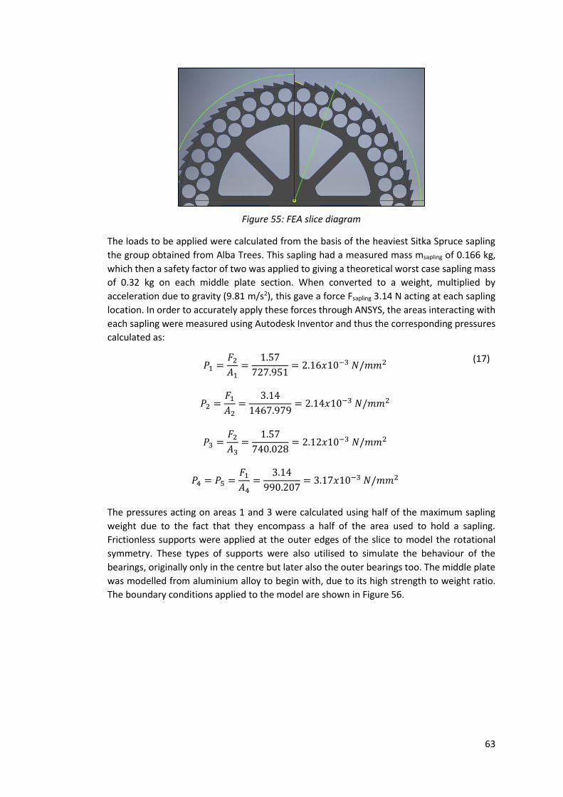
63
The loads to be applied were calculated from the basis of the heaviest Sitka Spruce sapling
the group obtained from Alba Trees. This sapling had a measured mass msapling of 0.166 kg,
which then a safety factor of two was applied to giving a theoretical worst case sapling mass
of 0.32 kg on each middle plate section. When converted to a weight, multiplied by
acceleration due to gravity (9.81 m/s2), this gave a force Fsapling 3.14 N acting at each sapling
location. In order to accurately apply these forces through ANSYS, the areas interacting with
each sapling were measured using Autodesk Inventor and thus the corresponding pressures
calculated as:
𝑃1 =
𝐹2
𝐴1=
1.57
727.951= 2.16𝑥10−3 𝑁/𝑚𝑚2
𝑃2 =𝐹1
𝐴2=
3.14
1467.979= 2.14𝑥10−3 𝑁/𝑚𝑚2
𝑃3 =𝐹2
𝐴3=
1.57
740.028= 2.12𝑥10−3 𝑁/𝑚𝑚2
𝑃4 = 𝑃5 =𝐹1
𝐴4=
3.14
990.207= 3.17𝑥10−3 𝑁/𝑚𝑚2
(17)
The pressures acting on areas 1 and 3 were calculated using half of the maximum sapling
weight due to the fact that they encompass a half of the area used to hold a sapling.
Frictionless supports were applied at the outer edges of the slice to model the rotational
symmetry. These types of supports were also utilised to simulate the behaviour of the
bearings, originally only in the centre but later also the outer bearings too. The middle plate
was modelled from aluminium alloy to begin with, due to its high strength to weight ratio.
The boundary conditions applied to the model are shown in Figure 56.
Figure 55: FEA slice diagram

64
Originally, bearing support for the middle plate was only considered in a central location and
results showed excessive deformation even at the larger plate thicknesses. For example, the
4mm model exhibited a maximum deflection of roughly 14 mm which is excessive when
considered against the 3 mm gap to the lower plate in the equilibrium position. The plots in
Figure 57 and Figure 58 illustrate the deformation behaviour and equivalent stress
distribution for the 4 mm thick model with only inner bearings considered.
If only central bearings were implemented the plate thickness required would be
approximately 8mm, increasing the weight of the overall machine dramatically. Thus it was
decided to incorporate additional bearings to support the middle plates at a radius just inside
Figure 56: ANSYS middle plate boundary conditions.
Figure 57: 4 mm aluminium deformation plat.
Figure 58: 4 mm aluminium equivalent stress plot.

65
the cassettes. In order to minimise weight, plastic ball bearings were sourced from igus [48]
and arranged as shown in Figure 59.
The simulations were then conducted for all thickness variations with these bearings
considered. Figure 60 and Figure 61 show the results of the simulations of a 4mm thick
middle plate made of aluminium with outer bearings considered.
The added support of the outer bearings led to a drastic reduction in the maximum
deformation experienced. For example, with outer bearings the maximum deformation in
the case of a 4 mm thick middle plate was roughly 0.4 mm, reduced from 14 mm with no
outer bearings. The magnitude and location of the maximum equivalent stress also changed
with the introduction of the outer bearings. The location was now at the section which was
Figure 59: Outer bearings location.
Figure 60: 4 mm aluminium with outer bearings: deformation plot.
Figure 61: 4 mm aluminium with outer bearings: equivalent stress plot.

66
supporting the sapling as opposed to at the joint between the spoke and central bearing
section.
With these deformation and equivalent stress results deemed as acceptable, the mass of the
entire Fast Loader system was calculated using 4 mm thick aluminium for the majority of its
make-up. The values obtained are detailed in Table 9.
Table 9: Fast loader mass in 4mm Aluminium
Section Volume (mm3) Density (kg/m3) Mass (kg)
Upper 10617041.19 2712 28.79
Middle 1581676.949 2712 4.29
Lower 2009279.183 2712 5.45
Total 38.53
As this total mass of the Fast Loader systems well exceeds the 25 kg guideline for individual
lifting without even including the mass of the 72 saplings, it was decided to carry out a
material study to investigate other suitable materials to enable reduction in the mass of the
Fast Loader system.
Material Analysis
The Fast Loader system will be subjected to a variety of environmental conditions, therefore
ensuring full operational capability in these environments is of critical importance. Further,
the loader may also be in contact with organic matter, oil, fuel and possibly even hydraulic
fluid. The Loader must also be lifted and moved around the site by the operator, so the
weight needs to be considered during material selection. The main requirements of the
material are listed below:
The material must maintain its structural integrity across a range of working
temperatures.
Must be water resistant.
Low reaction with alkalis and acids.
Scratch resistant and minimal friction are desirable.
The surface finish and the colour of the product are not vitally important, although
the colour scheme should tie in with the environment and the existing Bracke
colours.
Good surface hardness.
Easily fabricated.
Strong and lightweight.
Using CES Edupack, a range of suitable materials were identified based on operational
capability. It was decided that metals or plastics would be the most suitable material choice
based on strength and weight requirements. Initially aluminium was selected due to its
lightweight properties whilst still being relatively strong. However as previously analysed,
aluminium was too heavy to be considered suitable for use in the Fast Loader. The
performance of three plastics was therefore analysed.
67
POM (Polyoxymethylene)
Polyoxymethylene (POM) has many desirable qualities for use in harsh environments. A good
abrasion resistance and robustness is beneficial in an application where the loader will be
frequently handled. POM also demonstrates good surface hardness, fatigue resistance and
solvent resistance. These all increase the robustness of the Loader, helping to prevent
damage and increase the product life. A low coefficient of friction is beneficial where saplings
are required to drop from the loader under gravity. With a high resistance to water, the
loader manufactured from POM would operate well in a variety of different weather
conditions. POM is commonly found in a wide range of engineering applications, namely
bearing and automotive design therefore suitable under different load conditions and
robust.
However, POM is susceptible to damage from nitric acid and many other acids/alkalis; this is
an issue when being used outside because nitric acid is found in acid rain. There is a chance
that the acid rain could severely damage the Fast Loader. The other main issue with POM is
that its UV resistance is very poor unless carbon black is used to stabilise it. This would limit
the Fast Loader to being black in colour which is not ideal.
Acrylonitrile butadiene styrene (ABS)
ABS is suitable in a wide range of applications namely vehicle bumper design where a high
impact resistance is required. This thermoplastic polymer is suitable in the loader design
where robustness is a key attribute and a long product life is desirable. ABS can be used
across a large temperature range, with very little change in performance. The main
advantage when using it in a harsh outdoor environment, is that ABS resists acids, alkalis and
solvents very well. Knowing that the Loader will be in contact with water and chemicals, it is
beneficial to use a material that does not react easily. Forming ABS is a relatively simple
process and complex shapes can be formed, namely by injection moulding.
However, ABS has limitations in manufacture and applications. To be suitable in outdoor
applications, the polymer must be stabilised to increase UV resistance. ABS has poor
resistance to fatigue which would affect the life time of each Loader. High friction and wear
are common problems when using ABS, which would have an effect on the products life in
service.
Polymethylmethacrylate (PMMA)
Commonly noted as a thermoplastic glass alternative, PMMA is commonly found in a range
of outdoor applications and in high moisture environments. These all suggest that PMMA
performs well in a harsh outdoor environment. PMMA has excellent UV resistance and no
stabilisation or further treatment is required. PMMA shows good hardness, stiffness and it is
abrasion resistant with high tensile strength. All these characteristics suggest that the loader
would be extremely robust and hard wearing were PMMA the chosen material. It also has
excellent surface finish and gloss, so it is an aesthetically pleasing material to use.
The limitations when using PMMA include poor fatigue resistance and solvent resistance.
This may cause a decrease in the product life.

68
Comparison
Table 10: Plastics comparison
PMMA ABS POM
Price 1.68 £/kg 1.53 £/kg 1.58 £/kg
Density 1.18x10³ kg/m3 1.04x10³ kg/m3 1.4x10³ kg/m3
Young’s Modulus 2.7 GPa 2.21 GPa 2.5 GPa
Yield Strength 57.8 MPa 42 MPa 60.7 MPa
Poisson’s Ratio 0.365 0.391 0.37
A comparison of the selected polymer properties can be seen in Table 10: Plastics
comparison In terms of the shown characteristics PMMA can be seen as the strongest with
a Young’s modulus of 2.7 GPa although it is slightly more expensive than the other two
materials. The lightest material is ABS but it is also the weakest, this shows that density and
strength are related. From the data in the table PMMA is decided upon as the best material
for purpose. Then all the other characteristics that have been mentioned were considered.
There are a few disadvantages to PMMA, in areas where ABS and POM perform better. For
example the ABS and POM are more scratch resistant and have better fatigue resistance.
ABS is the best performer in terms of resistance to chemicals; this is a strong advantage over
the other materials. The main disadvantage of ABS and POM are the need to stabilize them
before they can be used outside. Outside use is the main characteristic of the material
needed. This reason and its superior strength have led to the PMMA being chosen as the
material for the Fast Loader.
PMMA Fast Loader Optimisation
Following on from the decision to utilise PMMA as the main structural material for the Fast
Loader system, it was decided to re-run the FEA analysis to optimise the middle plate
thickness under these new conditions. Again, the same loading conditions were applied and
the middle plate was modelled at a variety of thickness with a PMMA material model. The
deformation plot for the case of a 4mm thick middle plate made from PMMA is shown in
Figure 62.
Once more, the deformation at the outer edge of the middle plate was considered to be
excessive, with maximum values of more than 10mm. This set of analyses showed that for
satisfactory deformation and equivalent stress performance the middle plate would be
required to be at least 8mm thick PMMA.
Figure 62: 4mm PMMA middle plate with outer bearings: deformation plot.

69
However, with weight again paramount to thinking, it was decided to incorporate further
bearing supports at the outer radius to enable weight minimisation. The added bearings
were incorporated in a style similar to the outer bearings previously described, but at a radius
between the outer cassette holes and the radius of the ratchet teeth.
In order to validate the inclusion of the outermost bearings, and again optimise the middle
plate thickness, the FEA was again re-run for this latest configuration. The outermost
bearings were, as with the other bearings, were modelled as frictionless supports. The
deformation plot, for 4mm thick middle plate made of PMMA incorporating two outer
bearings, is shown in Figure 63.
The inclusion of the outermost bearings can be seen to have caused variations in the size and
location of the maximum deformation experienced on the middle plate. The maximum is
reduced, on a 4mm middle plate, from more than 10 mm to 0.367 mm and the location
moved from the outer radius of the middle plate to a location closer to where the saplings
are supported and the furthest from the bearing locations radially. In order to optimise the
thickness of the middle plate, the results were run for a variety of thicknesses between 2mm
and 10mm and the maximum deformation magnitudes plotted in Figure 64.
0
0.5
1
1.5
2
2.5
3
2 3 4 5 6 7 8 9 10
Max
imu
m D
efo
rmat
ion
(m
m)
Middle Plate Thickness (mm)
Maximum Deformation
Figure 64: Plot of maximum deformations vs. PMMA middle plate thickness.
Figure 63: 4mm PMMA middle plate with outermost bearings: Deformation plot.

70
This plot was used to define the optimal thickness as 3mm for the middle plate when using
PMMA as the main structural material. 3 mm was also chosen as the thickness for the other
two main components of the Fast Loader system, as these components have less load to
support. Thus the final mass of the system was calculated and are shown in Table 11.
Table 11: 3mm PMMA Fast Loader Mass
Section Volume(mm3) Density (kg/m3) Mass (kg)
Upper 7981829.952 1180 9.42
Middle 1238579.141 1180 1.46
Lower 1528170.046 1180 1.80
Total 12.68
When added to the 11.95 kg mass of saplings for each reloading cycle, this overall mass of
Fast Loader system is deemed acceptable versus the recommended limit of 25 kg.
Torque Handle Sizing
The incorporation of three concentric bearings adds value in more ways than simply
supporting the middle plate. The bearings are used to reduce friction and resistance to the
rotary motion required to “load” the Bracke P11.a carousel. Thus the effort required to turn
the middle plate through 5° as required would be minimal and easily achieved by any
operator. However, with regards to sizing the handle needed, the worst case scenario was
considered. In this circumstance the bearings and their effects are ignored, with the middle
plate considered to be directly contacting onto the lower part of the Fast Loader system and
the torque required to overcome the friction forces present calculated in a full loaded case.
From above, the mass of the middle plate is 1.46 kg and the mass of 72 saplings equates to
11.95 kg. Thus the overall mass acting onto the lower part of the Fast Loader system was
13.41 kg. When converted to a weight this was 131.55 N. Incorporating a coefficient of
friction of 0.54 [49], the force due to friction required to overcome was calculated as 131.55
x 0.54 = 71.037 N. Assuming load acts at a pitch circle diameter midway between the sapling
cassettes (radius=0.417m), the torque T required to rotate the middle plate:
𝑇 = 𝐹𝑓𝑑
𝑇 = 71.037𝑥0.417 = 29.62 𝑁𝑚
(18)
The average man can apply 100 N of force comfortably, so thus the length of handle required
was calculated:
𝑑ℎ𝑎𝑛𝑑𝑙𝑒 =
𝑇
𝐹𝑎𝑝𝑝𝑖𝑒𝑑
𝑑ℎ𝑎𝑛𝑑𝑙𝑒 =29.62
100= 0.296 𝑚
(19)
From this it was decided to design a handle of total length 600 mm which was 300 mm in
length either side of the central axis of the fast loader.

71
Ratchet and Pawl Concept
Ratchets and pawls are mechanical devices which allow rotation in a single direction and not
in the other direction [50]. The ratchet part is composed of a rotational gear with angled
teeth, and the pawl is a component which rests against the ratchet in order to restrict its
motion [51]. In the Fast Loader system, the required rotation during each reloading cycle was
5° and therefore the ratchet was designed to have 72 teeth. Thus during each reloading cycle
the operator simply turns the device through one click.
The maximum possible torque required to rotate the middle plate was calculated previously
as T=29.62 Nm. Thus it was possible to determine the maximum possible torque experienced
by the torsional spring within the pawl resisting rotation. With the torque applied at a pitch
circle diameter of 0.5 m, roughly the radial location of the pawl, the force experienced by
the end of the pawl was calculated:
𝐹𝑝𝑎𝑤𝑙 =
𝑇
𝑑
𝐹𝑝𝑎𝑤𝑙 =29.62
0.5= 59.24𝑁
(20)
Considering the pawl itself has a lever arm of length 0.11m, the maximum torque
experienced by the pawl was defined as:
𝑇𝑝𝑎𝑤𝑙 𝑚𝑎𝑥 = 𝐹𝑝𝑎𝑤𝑙𝑑
𝑇𝑝𝑎𝑤𝑙 𝑚𝑎𝑥 = 59.24𝑥0.11 = 6.52𝑁𝑚
(21)
Utilising a basic spring calculator [52], and values suitable to the dimensions of the designed
pawl it was capable to design a torsional spring capable of resisting maximum torques as
high as 128.6N-m. These values are well in excess of the maximum possible torque calculated
above, and thus the pawl design was deemed satisfactory.
Upper and Lower Part Connection
The upper and lower parts of the Fast Loader system were designed to be connected
together through the use of four M8 bolt and nut connections, spaced equally at 90°
intervals. These bolted connections would require to be able to resist the torque loading
applied when using the Fast Loader. Taking the maximum torque loading possible as
calculated above, T=29.62 Nm, this loading was split over the four bolts to give the torque
experienced by each as 7.405 Nm. At the pitch circle diameter of the bolts’ location this
translates to a force of:
𝐹𝑏𝑜𝑙𝑡 =
𝑇𝑝𝑎𝑤𝑙
4𝑑
𝐹𝑏𝑜𝑙𝑡 =29.62
4 𝑥0.56= 13.22𝑁
Using M8 bolts, first the inside diameter at the minimum diameter of the threads was
calculated to enable definition of the minimum shear supporting area. From [53], this was
defined:

72
𝐷𝑏𝑜𝑙𝑡 𝑚𝑖𝑛 = 𝐷𝑏𝑜𝑙𝑡 𝑚𝑎𝑥 − 1.082532𝑃
𝐷𝑏𝑜𝑙𝑡 𝑚𝑖𝑛 = 8 − 1.082532𝑥1.25 = 6.65𝑚𝑚
(22)
Where P is the pitch of the thread. Using this minimum diameter, the minimum area was
defined:
𝐴𝑏𝑜𝑙𝑡 =𝜋
4𝐷𝑚𝑖𝑛
2
𝐴𝑏𝑜𝑙𝑡 = 34.7𝑚𝑚2
(23)
However, with the bolt arrangement passing through both the upper and lower plates of the
Fast Loader system the components carrying the shear are doubled. Thus the area
experiencing the loading is doubled to Abolt = 69.4mm2. Next, the shear stress experienced at
each bolt location was calculated:
𝜏 =
𝐹𝑏𝑜𝑙𝑡
𝐴
𝜏 =13.22
69.4= 0.19𝑀𝑃𝑎
(24)
Often, shear strength is not specified for common bolt materials. However, it is safe to
compare experienced shear stresses with 60% of the material’s ultimate tensile strength to
check for integrity [54]. For an 8.8 grade M8 bolts, the ultimate tensile strength (UTS) is 830
MPa [53], thus 60% of UTS is 498 MPa. It can be seen from these numbers that the four M8
bolts are more than sufficient for the small amount of shear stress experienced due to the
torques induced by rotating the Fast Loader’s middle plate.
Orientation
A key consideration in the design of the Fast Loader system was how it would attach to the
existing Bracke P11.a carousel. It was critical that the Fast Loader system could orientate
onto the Bracke carousel such that both sets of cassettes line up perfectly and reloading can
occur successfully. The design solution to this challenge was to tack weld nuts onto four
radially equal locations as shown in Figure 65.
Figure 65: Tack welded bolts (4 in black).

73
These nuts would then be utilised to enable a variable diameter shaft with threads at each
end to be threaded into location and used to guide the orientation of the Fast Loader system
as shown in Figure 66.
Finally, the Fast Loader system could be fixed in the correct orientation through the use of
four quick-release star grips, threaded onto the top end of the variable diameter shafts.
These quick-release star grips work by tilting over a threaded spindle, then being brought
into a straight position and turned a fraction of overall rotation to achieve the required
clamping. Thus the time to fix the orientation is minimised. Similarly, the quick-release works
in much the same way but in reverse enabling rapid removal of the Fast Loader system. The
operation of the quick-release star knobs is shown in Figure 67.
Figure 66: Nut, varied diameter stud and quick release star
knob diagram.
Figure 67: Quick-release star knob operation [59].

74
4.5.3.5 Final Fast Loader Design With the materials defined and the thicknesses optimised, the torque handle and pawl
separately sized, and the internal and external connections verified; the Fast Loader design
was finalised and the concept modelled using Autodesk Inventor. The final 3D CAD model is
shown in Figure 68 with a further assembly drawing illustrated in Appendix A12.
Figure 69 illustrates the internal workings of the Fast Loader, namely the ratchet and pawl
concept utilised to control the rotation of the middle plate when loading saplings to the
Bracke P11.a carousel.
The Fast Loader design enables the operator to minimise the time spent on each reloading
cycle as it gives the ability to simultaneously load 72 saplings if desired. The exact timings
have not been able to be defined in order to quantify exactly the improvement made,
however if the concept was to be manufactured into a prototype it would be recommended
that a time study such as this was conducted.
It would also be recommended that more than one Fast Loader would be manufactured for
each planting machine such that prior loading could be completed at the nursery before
sapling delivery to site. The benefit of prior loading would be further process time savings
associated with the manual loading of saplings into boxes currently conducted at forestry
nurseries across Scotland. With experienced operators able to plant approximately 1200
Figure 68: Final Fast Loader system
Figure 69: Final Fast Loader ratchet and pawl

75
saplings in one working day, 17 Fast Loaders would be required to be pre-loaded ahead of
each day’s work. However, due to the physical scale of the Fast Loader system, it is
anticipated that this would be unrealistic and would cause numerous transport problems
between nursery and planting site. Thus the group recommend the manufacture and use of
four Fast Loader systems with each enhanced planting machine, coupled with existing sapling
storage boxes to transport the remaining saplings required each day. Critical to ensuring the
process optimisation would be the employment of a further worker whose principle role
would be to reload the Fast Loader system as the excavator operator continues to plant
saplings. Although an added expense, this extra pair of hands could be utilised to monitor
planting quality as operations continue and the Fast Loader system remains loaded. This is a
task which is commonly completed when the planting machine is non-operational by the
excavator operator, adding cost and time to the overall planting process. Further work is
required to define the optimal transport system required for the use of Fast Loader systems
and also to quantify the improved performance of the concept with regards sapling reloading
time versus the existing manual reloading process. A cost analysis should also be conducted
to validate the employment of a further worker within the process.
4.6 Final Models for Simulation
4.6.1 Existing Bracke P11.a Model As the simulation is being used to train new operators on using a mechanical planter, it was
decided to produce a full 3D model of the original Bracke P11.a. This allowed Simultech the
choice between the original and the enhanced, they could also produce a simulation of both
if desired. The final assembly was compiled on Autodesk Inventor 2016 and can be seen in
Figure 70.
Figure 70: Final CAD rendering of existing
Bracke P11.a planting machine

76
4.6.2 Craobh Planting Enhanced Model Once the individual components of the Bracke P11.a and the improved design had been
modelled they were assembled in Autodesk Inventor 2016 to create the final enhanced
design. The final project model can be observed in Figure 71. Concluding the modelling of
the planting machine, each of the final designs from the various design phases, including the
unchanged components, scarifying blade and Fast Loader were all combined together to
create a working prototype that would be suitable for simulation. In order to create a
working model, all aspects of design throughout the project were considered including
hydraulic and material design to ensure that the overall design solution would be suitable
for working in a forestry operation. It is important to note that where all machine
components were considered on a conceptual level, only critical moving components were
further developed in a more detailed design process. These components were in line with
the required outcomes from the problem statement in the earlier phases of the project. The
model files have been handed to Simultech where they will be forwarded into simulation.
Further an exploded assembly of the final planting machine design is illustrated in Appendix
A13.
5.0 Reflection Reviewing the success of the project both in terms of technical achievement and group
interaction presents an opportunity to reflect on overall performance and identify where
objectives were met and where improvements could be made with further investigation.
Although the main focus for the project was on developing an enhanced mechanical planting
machine for use in simulation, a critical aspect to its success was how the team functioned,
how decisions were made and how objectives were met.
5.1 Design Process Reflection In the early stages of the design, it was critical that the opinions of every group member were
heard to ensure that all design ideas were considered. After each visit made to external
companies, the group were able to sit down and discuss what each member had learned
from the information voiced by industry experts. By understanding what each member had
gained from the visits, it allowed for a comprehensive critical analysis to be developed. It is
Figure 71: Final CAD renderings of enhanced planting machine
with and without Fast Loader system.

77
also important to note that to ensure effective time management in this information
development phase that each person took on a different topic of research. Ensuring that the
entire group understood the various technologies, each member was responsible for
explaining to the others what had been learned. This development phase, considering both
independent learning and group learning through visits to various places allowed for each
individual to gain an understanding of the technologies behind the project in hand at the
same time establish an effective method of communication between everyone.
From this initial research and understanding of the various existing technologies the group
were able to devise a comprehensive specification of capabilities of the enhanced design for
the planting machine. This was devised with the help of Prof Nash and Mr McArthur to
ensure that proposed deliverables were within the scope of the project and the ability of the
group. As a project similar to this had never been carried out before within the university, it
was important that the group were able to define some underlying fundamentals of forestry
design however it is also important to note that designing for simulation meant that full
detailed design similar to that for manufacture. For this reason, the group decided to focus
on the enhancement of critical moving components of the forestry machine, looking in
particular at the loading and discharging of saplings from the machine and also the
mechanism required to provide sufficient mounding and compaction capabilities to the soil
for enhanced protection of the sapling. Although important to the generation of an
enhanced planting machine, the complex control through hydraulics and electronics was not
developed any further from conceptual design. It was learned through speaking to operators
of existing machines that these systems operated well at present and as such, time was
directed at developing fully the critical moving components. However, this would provide a
basis for future investigations perhaps looking solely at the electronic control of the machine
to be integrated with the final designs of this project.
5.2 Project Management Reflection Throughout the detailed design phase, the group were able to present sections along the
way to Prof Nash, Mr McArthur and various companies who were all able to direct any issues
with the proposed designs in the right direction and identify further areas for the group to
develop upon. By maintaining a continuous communication link between industry experts
and the projects clients, objectives could remain precise and the group could focus on
ensuring the deliverables were in line with the requirements of the project scope. This also
ensured that the group remained efficient in carrying out tasks and each member had a
specific focus.
Scheduling of tasks was a critical concern throughout the project. To ensure that tasks
remained on target and deadlines were achieved, a Gantt chart was devised with all the
required tasks, as specified in the contract, outlined alongside theoretical start and
completion dates. It became apparent as the project progressed that the progress chart
would require constant monitoring and updating to ensure that deadlines were not missed
and that extra time was available in the event of a delay. Identifying all major occurrences
throughout the duration of the project, only two delays were significant enough to pose a
threat to the completion of the project. Firstly, it was suggested to the group that a visit be
made to view the existing market leading planting machine in operation. This however
proved difficult as the machine was constantly operating across a large geographical area
and travel arrangements could not be accommodated due to constraints out with the control
of the group. In February, the machine was operating within a respectable travel distance

78
and as such the group were able to make a visit three months behind schedule. If the group
had been able to complete this visit earlier in the year then benefits would have been felt
throughout the critical analysis phase and the design process enhanced.
Critical to the success of this project was effective team management and ensuring that at
no point any member was unsure of a task. This meant that communication was vital and
was made more complicated with the inclusion of an Erasmus student and a Japanese
student both on exchange. However, it was identified that with clear communication and an
instant messenger chat page set up online, that effective decision making discussions could
be had both in company and independently. Identifying the scale of the project and the
number of components to be designed, it was decided early on that effective time
management could be established by splitting design sections into sub groups. This allowed
for team members to focus on specific aspects of the design and become fully engaged in
the phase relevant to them. On a regular basis, meetings were held with the whole group to
discuss progress and identify further areas of development. It is important to note that the
final design incorporated integrated parts and as such the group had to remain responsive
in engaging in all sections of design so as in the final assembly, components would fit
together accordingly. With limited time to the final deadline, effective time management
was critical to the success and completion of all aspects of the project. With other deadlines
and commitments around the same time as the project deadline, it was imperative that each
group member monitor the progress of each other to ensure that no aspects of the design
quietly lapsed.
By developing a design suitable for simulation, it presented the group with the opportunity
to design using CAD software. As outlined early in the project, the strengths and weaknesses
of each individual were outlined to identify the most suitable roles for the right people. All
CAD design was conducted on Autodesk Inventor to accommodate for the expertise of two
of the group members on said software. Around this, the other group members were able to
focus time on developing other aspects of the design to ensure that all deliverables were
completed by the due date. By accommodating for group members, it was identified that the
design phase was more efficient and less time was required learning new software and
developing new skills. Once again, by maintaining a clear line of communication between
members, this phase developed with only minor flaws, which were always quickly corrected
and the final design presented to the project clients.
Towards the end of the project, other commitments to study and personal circumstances
became more apparent as the workload increased trying to meet the final deadline with all
aspects of the design accounted for. Other engagements from group members were
identified well in advance, allowing for contingency plans to be employed. In some
circumstances this would include accepting a slight delay in non-critical work being carried
out. Where it was identified that tasks would have a direct influence on further stages in the
design, group members were swapped into different roles and to complete different aspects
of the design work. This was made possible by engaging in a comprehensive study of the
design and operating industry as a full group early in the project. An example of this occurred
in the design phase where two group members were focussed on the enhancement of
sapling reloading. These members required information from external sources. However by
reallocating to the Head of Communications this task was completed quicker, allowing the
other member to focus on other tasks.

79
As outlined throughout the reflection, risk management was a critical element of effective
project management ensuring that any issues that did occur were mitigated immediately to
minimise disruption. As outlined in section 2.8 potential risks were outlined early on in the
project so as the group were made aware of issues that may arise and to ensure that
contingency plans were available should an issue arise. On the whole, this was managed
effectively by the group aside small delays as outlined.
In the beginning, the group was devised of five members, however this decreased to four in
semester two as Kazuki Iida left the group to return home after a one semester exchange.
Allowing Kazuki to manage a project phase in semester one enabled a more involved
engagement in the project. As the project progressed on to semester two with detailed
design, the lesser number in the group meant distributing a greater workload over the
remaining team to match the number of tasks required to be completed ahead of the
deadline. However, this was recognised well in advance and as such did not present itself as
a major issue at the start of semester two.
5.3 3D Printing Challenges Lead times for manufacture of 3D printed components presented a significant delay for the
small experimental analysis set up to measure the performance of a variety of different blade
types. Drawings were provided to the department at the beginning of week three and the
final components not finished until the middle of week six. However, overall quality of the
models was substandard to what was required for the testing. It was also made aware to the
group that one model had failed to print at all and that to fix this, the model would have to
be redesigned or the printing outsourced elsewhere. Taking the advice of outsourcing, the
rapid prototyping centre within the DMEM department were contacted and the drawings
handed over on the basis that a quote would be given for the cost of the printing. For reasons
beyond the control of the group, two follow up emails went unheard before the group
approached the department to be told that only laser cutting would be suitable for the
profiles. This was a significant setback in the design of the blades and as such had an impact
on the progress of the final design.
These setbacks had a significant influence on the progress of design, however it was proved
that the team were able to overcome such issues effectively so as not to affect any further
areas of the project. From learning of the outcome from DMEM, the group reconvened to
make a decision about the blade profiles for testing. It was decided that the cost of laser
cutting could not be justified for the reason that the blade profiles being printed may not
have actually been the final design and so would not represent the project after testing.
Further, having waited up to five weeks for any progress, the project time constraint
hindered further development. From this, the low quality profiles were reworked by
members of the group to produce profiles that would be adequate for the purposes of testing
at a fraction of the original cost.
5.4 Academic vs. Industrial Representatives The nature of the project involved both academic and industrial aspects, with a key
stakeholder representing each. Presenting the progress of the project and the work in a
manner appropriate for these two audiences was a challenge for a group composed of
students more familiar with the academic style. However, close collaboration during the
numerous site visits conducted enabled the group to establish a close working relationship
with their industrial representative and thus communication was generally clear and

80
productive. By participating in numerous and varied site visits the group further established
useful contacts in not only the forestry but also heavy engineering industries, whose
experience and guidance proved invaluable throughout the design process.
5.5 Further Investigations Based on the final design of the project, it provides a solid foundation to speculate on further
design work that could be conducted in future project investigations. Firstly, it was identified
that the group would focus effort on enhancing major critical moving components of the
planting machine with only a conceptual design being focussed on the hydraulic control and
electronic design within the control system. From this it is possible to suggest that future
investigations could be outsourced across different faculties, focussing solely on the
electronic design. This was identified from an early stage as being out with the scope of the
present group.
With the end objective to operate this design in a simulation environment, less of an
emphasis was placed on constraints of manufacture such as considering materials and
machining processes. If this design was to be carried into manufacture phase then it would
present an opportunity for further detailed investigation to ensure an economic production
process was available.
If this project was to be continued with a further investigation, it would be important to pass
on the developed knowledge and information gained through meeting with a wide variety
of industry experts. This could be done through continuing with a strong presence on social
media and making the new project group aware of the wide contact base that was developed
throughout the duration of this project. It proved invaluable to the current group having the
ability to contact relevant companies to gain information on certain topics and receive advice
at times of uncertainty.
Further investigation would be possible in relation to the challenge of reducing machine
downtime required for sapling reloading. Focus should be given to increasing the reliability
and reducing the weight challenges faced by current tray-wise loading concepts, as these
concepts have the best potential for increasing the overall productivity of mechanised
planting. However, collaboration with nurseries around Scotland would be required in order
to gain agreement on the standardisation of cultivation trays required for successful tray-
wise reloading. The Fast Loader concept developed within this report requires further
attention to the design of the transport system, enabling optimal time reduction in the
overall reloading process. Also, a prototype should be manufactured to allow quantification
of the time reduction enabled by simultaneous reloading of 72 saplings as opposed to
manual piecewise reloading.
6.0 Conclusion On the whole, the project has been a success. Through following a strategic design approach
to the initial problem, the group were able to develop a solution, based on existing designs,
suitable for use in simulation. By focussing on critical moving components of the planting
machine, each member was able to practice knowledge learned from previous years at
university as well develop a new understanding of engineering principles in a more refined
field. This, on top of effective team management and an effective working relationship
between all members and clients overall enhanced the outcome of the project.

81
From this, the final design, as well as models of existing components, will be handed over to
Simultech Scotland for further enhancement before being developed into a simulation model
for the purposes of training and development in the field of forestry engineering. The final
design can be compared with the existing Bracke design to show where design
enhancements have been made with respect to improving the overall planting process. Both
designs will be made available to Simultech, with a view to further future projects continuing
to develop the machine and the various components.

82
7.0 References
[1] “Timber and Forestry Products,” 2014. [Online]. Available:
http://www.environment.scotland.gov.uk/get-informed/land/timber-and-forestry-
products/.
[2] A. Lawrence and D. Edwards, “Prospects for new productive woodland in Scotland:
Insights from stakeholders,” 2013.
[3] Belbin, “Belbin Team Roles,” Belbin, [Online]. Available:
http://www.belbin.com/about/belbin-team-roles/. [Accessed 30 January 2016].
[4] Forestry Commission Scotland, “Scotlands Forests and Biodiversity,” 2015. [Online].
Available: http://scotland.forestry.gov.uk/supporting/strategy-policy-
guidance/biodiversity.
[5] D. I. Steve Morgan, “Excavator Mound Spacing on Restocking Sites,” 2004. [Online].
Available:
http://www.forestry.gov.uk/website/publications.nsf/DocsByUnique/9D425CFE8F0
6682080257EBB0046FA7C.
[6] B. T. Errson, “Concepts for Mechanised Tree Planting in Southern Sweden,” Umea,
2014.
[7] “Scotlands Soils,” 2015. [Online]. Available: http://www.soils-
scotland.gov.uk/about/impact.
[8] Forestry Commission, “Sitka Spruce - picea sitchensis,” [Online]. Available:
http://www.forestry.gov.uk/forestry/infd-5nlej6.
[9] The James Hutton Institute, “The land capability for forestry,” [Online]. Available:
http://www.soils-
scotland.gov.uk/documents/Land_Capability_for_Forestry_description.pdf.
[10] Bracke Forest, “P11.a Planter Brochure,” 2014. [Online]. Available:
http://www.brackeforest.com/app/projects/brackeAllNew/images/P11aENWeb.pdf
[11] M. Sigurdh, “Mechanised planting with Eco-Planter in southern Sweden,”
Institutionen för skogens produkter och marknader, 2004.
[12] “Risutec Softwood Planting Machines,” Risutec, 2016. [Online]. Available:
http://www.risutec.fi/en/products/softwood.
[13] “Risutec PM60,” Risutec, 2016. [Online]. Available:
http://www.risutec.fi/en/products/softwood/pm60.
[14] “Risutec Tk-120 and TK-200,” Risutec, 2016. [Online]. Available:
http://www.risutec.fi/en/products/softwood/tk.
[15] “Husqvarna Group,” 2015. [Online]. Available:
http://www.husqvarnagroup.com/en.

83
[16] “Overkill Interstellar,” 2015. [Online]. Available:
http://iloapp.overkillinterstellar.com/blog/blog?ShowFile&doc=1274376468.pdf .
[17] 2015. [Online]. Available: http://www.greendiary.com/tree-planting-robot-helps-
faster-reforestation.html .
[18] 2015. [Online]. Available: www.biocarbonengineering.com.
[19] John Deere, “Harvesters,” 15 March 2016. [Online]. Available:
https://www.deere.co.uk/en_GB/products/equipment/wheeled_harvesters/wheele
d_harvesters.page?.
[20] John Deere, “Harvester Heads,” 15 March 2016. [Online]. Available:
https://www.deere.co.uk/en_GB/products/equipment/harvesting_heads/harvestin
g_heads.page?.
[21] Ponsse, “Harvester Heads,” 15 March 2016. [Online]. Available:
http://www.ponsse.com/products/harvester-heads.
[22] John Deere, “Forwarders,” 15 March 2016. [Online]. Available:
https://www.deere.co.uk/en_GB/products/equipment/forwarders/forwarders.page
?.
[23] John Deere, “Skidders,” 15 March 2016. [Online]. Available:
https://www.deere.co.uk/en_GB/products/equipment/skidders/skidders.page?.
[24] CAT, “Skidders,” 15 March 2016. [Online]. Available:
http://www.cat.com/en_US/products/new/equipment/skidders.html.
[25] Engcon. [Online]. Available:
http://static.engcon.se/uploads/423/related/engcon_ec15b_int-1.pdf.
[26] Helac, “Helac Powertilt,” 2014. [Online]. Available:
http://www.helac.com/uploads/file/attachments/product-
brochures/PowerTilt_brochure_022514.pdf.
[27] S. Balu, “What are the Basic Principles of Hydraulics?,” Bright Hub Engineering, 25
July 2009. [Online]. Available: http://www.brighthubengineering.com/hydraulics-
civil-engineering/43171-what-are-the-basic-principles-of-hydraulics/. [Accessed 10
March 2016].
[28] “Helac Powertilt,” 2015. [Online]. Available:
https://www.helac.com/uploads/file/attachments/product-
brochures/PowerTilt_brochure_022514.pdf.
[29] 2016. [Online]. Available: http://www.digrock.com/Files/CE_PriceBook.pdf.
[30] “Hydraulics Online,” [Online]. Available:
http://www.hydraulicsonline.com/hydraulic-calculations.
[31] JCB, Hydraulic Excavator JS145 Brochure, 2015.

84
[32] “Bucket Terminology for Hydraulic Excavators,” [Online]. Available:
http://www.cwsindustries.com/images/pdf/techdata/bucket_terminology.pdf.
[33] Forestry Commission, Duncan Ireland, “Traction Aids in Forestry,” 2006. [Online].
Available: http://www.forestry.gov.uk/pdf/FCTN013.pdf/$FILE/FCTN013.pdf.
[34] I. Murgatroyd and C. Saunders, “Protecting the environment during mechanised
harvesting operations,” Forestry Commission, 2005. [Online]. Available:
http://www.forestry.gov.uk/pdf/fctn011.pdf/$FILE/fctn011.pdf.
[35] “Tiltrotator EC15B,” 2015. [Online]. Available: http://engcon.com/uk/en/engcon-
uk/products/excavators/tiltrotators/product.html?productName=EC15B.
[36] S. Pugh, Total Design, Addison Wesley, 1991.
[37] Caterpillar, “CAT buckets and ground engaging tools,” 2016. [Online]. Available:
http://www.finning.co.uk/_documents%5CParts%5CPartsSolutions%5CGroundEnga
gingTools%5CCat%20Excavator%20Buckets.pdf.
[38] Universidad de Oviedo, “Actuators - Lecture Slides,” 2015. [Online].
[39] B. Ersson, U. Bergsten, Lindroos and O., “Reloading mechanized tree planting
devices faster using a seedling tray carousel,” Silva Fennica, vol. 28, 2014.
[40] L. Ohman, “Trials with the Bracke Planter on fertile sites in Stragnas and Holmen
forest districts.,” Skogsvardsavdelningen, 1994.
[41] J. Rantala, P. Harstela, V. Saarinen and L. Tervo, “A techno-economic evaluation of
Bracke and M-Planter Tree Planting Devices.,” Silva Fennica, vol. 43, pp. 659-667,
2009.
[42] B. Ersson, U. Bergsten and O. Lindroos, “The Cost-Efficiency of Seedling Packaging
Specifically Designed for Tree Planting Machines,” Silva Fennica, vol. 45, 2011.
[43] M. Keane, “Container plants and mechanised planting- The way forward?”.
[44] T. Pyykkonen, “M-Planter Brochure,” [Online]. Available: http://www.m-
planter.fi/File/M-Planter__ENG_.pdf?572286. [Accessed 12 March 2016].
[45] U. B. a. O. L. Back Tomas Ersson, “Reloading mechanized tree planting devices
faster,” Silva Fennica, vol. 48.
[46] T. L. a. V.-M. Saarinen, “Comparative study of the Risutec Automatic Plant,” Silva
Fennica, vol. 48, 2014.
[47] HSE, “Manual handling at work,” [Online]. Available:
http://www.hse.gov.uk/pubns/INDG143.pdf. [Accessed 08 March 2016].
[48] igus, “xirodur B180 plastic tube,” igus, [Online]. Available:
http://www.igus.co.uk/wpck/7170/xiros_B180_Polymerkugelrolle. [Accessed 14
March 2016].

85
[49] Matbase, “PMMA Material Properties,” Matbase, [Online]. Available:
http://www.matbase.com/material-categories/natural-and-synthetic-
polymers/commodity-polymers/material-properties-of-polymethyl-methacrylate-
extruded-acrylic-pmma.html#properties. [Accessed 8 March 2016].
[50] W. Berg, “Ratchets and Pawls,” Berg, [Online]. Available:
http://www.wmberg.com/Products/Ratchet-Pawl-Gears.aspx. [Accessed 10 March
2016].
[51] F. D. Jones, Ingenious Mechanisms For Designers and Inventors, New York:
Industrial Press Inc., 1951.
[52] T. S. Store, “Torsional Spring Calculator,” Acxess Spring, [Online]. Available:
http://www.acxesspring.com/spring-calculator.html. [Accessed 13 March 2016].
[53] E. Oberg, F. Jones, H. Horton, H. Ryffel and R. Green, Machinery's Handbook, New
York: Industrial Press, 1996.
[54] Fastenal, “Technical Reference Guide,” [Online]. Available:
http://www.fastenal.com/content/documents/FastenalTechnicalReferenceGuide.pd
f. [Accessed 12 March 2016].
[55] Soil Standards of Scotland Staff, “Soil maps of Scotland at a scale of 1:250 000,”
Macaulay Institute for Soil Research, Aberdeen, 1981. [Online]. Available:
http://www.soils-scotland.gov.uk/data/soil-survey.
[56] “Scotlands Soils,” 2016. [Online]. Available: http://www.soils-
scotland.gov.uk/data/soil-lcf.
[57] 2015. [Online]. Available: http://www.kwf-
online.de/deutsch/information/markt/b2400.htm.
[58] Carlos Javier Martin Lucas, “Automatizacion Hidraulica,” 2015.
[59] “Berger Tools,” 2016. [Online]. Available: https://www.berger-
tools.co.uk/images/original/SILD_GN6336.3_Star_Knob,_Quick_Release,_Plastic,_St
eel_Bush_536.gif.

Appendix A1: Original Plan (Semester One)

Appendix A2: Original Plan (Semester Two)
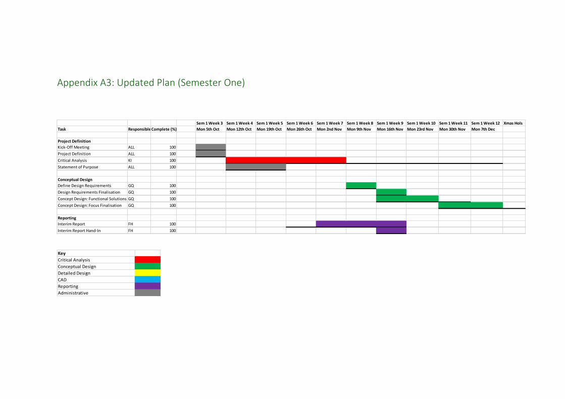
Appendix A3: Updated Plan (Semester One)
Sem 1 Week 3 Sem 1 Week 4 Sem 1 Week 5 Sem 1 Week 6 Sem 1 Week 7 Sem 1 Week 8 Sem 1 Week 9 Sem 1 Week 10 Sem 1 Week 11 Sem 1 Week 12 Xmas Hols
Task ResponsibleComplete (%) Mon 5th Oct Mon 12th Oct Mon 19th Oct Mon 26th Oct Mon 2nd Nov Mon 9th Nov Mon 16th Nov Mon 23rd Nov Mon 30th Nov Mon 7th Dec
Project Definition
Kick-Off Meeting ALL 100100
Project Definition ALL 100
Critical Analysis KI 100
Statement of Purpose ALL 100
Conceptual Design
Define Design Requirements GQ 100
Design Requirements Finalisation GQ 100
Concept Design: Functional Solutions GQ 100
Concept Design: Focus Finalisation GQ 100
Reporting
Interim Report FH 100
Interim Report Hand-In FH 100
Key
Critical Analysis
Conceptual Design
Detailed Design
CAD
Reporting
Administrative

Appendix A4: Updated Plan (Semester Two)
Sem 2 Week 1 Sem 2 Week 2 Sem 2 Week 3 Sem 2 Week 4 Sem 2 Week 5 Sem 2 Week 6 Sem 2 Week 7 Sem 2 Week 8 Sem 2 Week 9Mon 18th Jan Mon 25th Jan Mon 1st Feb Mon 8th Feb Mon 15th Feb Mon 22nd Feb Mon 29th Feb Mon 7th Mar Mon 14th Mar
Mon 18th Jan Mon 25th Jan Mon 1st Feb Mon 8th Feb Mon 15th Feb Mon 22nd Feb Mon 29th Feb Mon 7th Mar Mon 14th Mar
Final Report FH 100
Final Report Hand-In FH 100
Detailed Design GQ
Detailed Design: Soil Compaction FH+ICC 100
Detailed Design: Levelling FH 100
Detailed Design: Sapling Reloading GQ+KJ 100
Detailed Design: Entire Concept GQ 100
Detailed Design Finalisation GQ 100
CAD Modelling ICC
CAD Modelling: Original Device ICC+GQ 100
CAD Modelling: Updated Blade ICC 100
CAD Modelling: Leveller FH 100
CAD Modelling: Updated Carousel GQ 100
CAD Modelling: New Concept AssemblyALL 100
CAD Modelling: Animation ICC 100
3D Printing
3D Printing Procurement KJ 50
3D Printing KJ 50
Website
Website Creation ICC 100
Key
Critical Analysis
Conceptual Design
Detailed Design
CAD
Reporting
Administrative

Appendix A5: Product Design Specification As harvesting rates of round wood continues to exceed planting rates of new saplings,
there introduces a gap in the forestry machine market for a product capable of
reforesting areas at a similar rate to those used for deforestation. At present, few
planting machine designs are used in the industry. Amongst those, the P11.a
manufactured by Bracke Forest is a machine designed to operate as an attachment
to a 360° tracked excavator.
With an opening in the market and a demand for large areas of Scotland to be
reforested with saplings for future harvesting, craobh planting aim to enter this niche
with the aim of identifying weaknesses in current machines in production and
conducting a thorough design exercise, introducing ideas to increase productivity and
efficiency of the mechanical planting machine.
This Product Design Specification (PDS) was drawn up by the group following a critical
analysis phase of the current industry. After discussion, the main issues outlined as
areas for improvement included:
Increasing seedling carrying/planting capacity. The Bracke P11.a has the
ability at present to carry 80-120 saplings.
Increasing planting rate with a faster mounding and sapling insertion process.
The Bracke P11.a currently plants with a productivity of approximately 300
plants per hour.
Optimising overall weight of the machine with no compromise on
productivity or structural integrity. The Bracke P11.a weighs 1100kg.
Maintain verticality of planting to ensure maximum survival rate of sapling
on inclined terrain.
Amongst the mains areas for improvement, craobh planting aim to identify the overall
current situation in forestry and the machines available to develop an optimised machine
capable of outperforming current competitors and reducing the overall downturn of
planting capabilities in Scotland.
1.0 Performance
1.0 Shall be able to plant a sapling vertically.
1.1 Shall be able to operate on variable terrain, with varying gradients up to
30°.
1.2 Storage capacity shall be minimum of 200 saplings at one time.
1.3 Shall be capable of planting 2,500-3,000 saplings in one day.
1.4 Shall be able to plant 2,700 saplings per hectare.
1.5 Shall be capable of creating mounds with specific dimensions (20-30cm high
and 0.25m2).
1.6 Shall be able to plant saplings of varying heights.
1.7 Coupling hitch shall be designed to be suitable for connection to various
prime movers.
1.8 Shall increase productive work time by reducing overall time required for
reloading sapling cartridge to ≤10 % of productive work time.
2.0 Environment
2.0 Product shall operate to full capacity in adverse weather conditions.
2.1 Shall be corrosion resistant in both functionality and material selection.
2.2 Shall be able to operate to full capacity in all soil conditions typical to
Scotland.
2.3 Must be able to resist impact loading, caused by tree stumps and rocks.
2.4 Shall operate to full capacity in a dirty environment.
2.5 Shall be resistant to general forestry equipment wear and tear.
2.6 Product should perform to full capacity and not be damaged by
temperatures in the range of -20°C to 70°C.
2.7 Shall consider compaction issues, with regards soil aeration and also mound
compaction.
2.8 Shall only perform localised soil scarification, as opposed to across site
trenching required for manual planting.
3.0 Maintenance
3.0 Shall require minimal maintenance with exception of light lubrication if and
when required.
3.1 Design shall incorporate easy access to mechanical moving components.
3.2 Where screws, bolts and washers are used, British standards must be
complied with.
3.3 Aftermarket sales and services shall be made available.
3.4 Maintenance shall only require general tools.
4.0 Materials
4.0 The chosen materials shall be resistant to wear and tear e.g. scratch and
panel dent resistant.
4.1 Materials chosen shall be resistant to corrosion and rusting.
4.2 Materials chosen shall retain structural integrity in environments with
temperatures ranging from -20°C to 70°C.
4.3 The materials shall be as lightweight as possible, however structural
strength and rigidity must not be compromised.
4.4 Environmentally friendly materials shall be used for manufacture.
4.5 The materials chosen shall be malleable and formable in manufacture.
4.6 Readily available and commonly used materials for manufacture would be
preferable.
5.0 Weight
5.0 Must not weigh more than 1500kg.
5.1 Product weight must not affect performance of tracked excavator.
5.2 Weight of design shall be reduced as far as possible, however structural
strength and rigidity must not be comprised.
5.3 Lashing point shall be incorporated to enable easy transportation.
6.0 Size
6.0 Size shall be kept to a minimum, in order to reduce cost and power required
and increase manoeuvrability.
6.1 Connection dimensions constrained by proportions of universal attachment
hitch.
6.2 Size of scarifying blade is constrained by dimensions of mound required (see
‘Performance’)

6.3 Size of product will be constrained by sapling storage requirements (see
‘Performance’)
7.0 Shipping
7.0 Shall be transportable with 360° tracked excavator.
7.1 Shipping of saplings shall be considered to incorporate easier reloading of
planting machine.
7.2 Lashing point shall be incorporated to enable easy transport.
8.0 Quantity
8.0 Must be able to entice custom through a full rental package. 5 units to be
manufactured and made available across Scotland for contract hire.
8.1 Virtual design package to be made available for simulation training.
9.0 Competition
9.0 Dominance of manual planting within Scottish market.
9.1 Mechanised planting market led by Bracke Forest.
9.2 Shall improve on compaction issues experienced using Bracke machine.
9.3 Shall improve on sapling storage capabilities of other mechanised planting
machines (around 120 saplings at one time).
9.4 Shall improve on abrasion issues with current Bracke carousel sapling
delivery.
10.0 Market Constraints
10.0 The device shall be marketed on a trial basis within Scotland and, if
successful, will be marketed worldwide.
10.1 Connection to excavator shall be through a universal attachment hitch
found on a 360° tracked excavator.
10.2 Availability of standard parts (screws, nuts, bolts, etc) shall be considered
during design.
10.3 Availability of hydraulic parts shall be considered during design of joints
etc.
10.4 Prime mover shall be a 360° tracked excavator.
11.0 Customer
11.0 Customers shall be from the forestry industry and general groundworks
contractors.
11.1 Product shall be suitable for simulation by Simultech Scotland.
11.2 Performance shall be prioritised over aesthetics.
12.0 Safety
12.0 All moving components shall be appropriately covered.
12.1 Design must meet all industry safety regulations.
12.2 Sharp edges shall be avoided or covered where possible.
12.3 Risk of injury when loading saplings shall be kept to a minimum.
12.4 Attachment of planting machine shall be considered to prioritise safety and
conducted by an experienced operator.
13.0 Standard Specifications
13.0 At present no British Standards exist for planting.
13.1 Must conform to procedures and specifications currently in place using
existing techniques.
13.2 Must follow existing health and safety standards, in place both by machine
manufacturer and planting contractor/landowner.
14.0 Ergonomics

14.0 Must be able to operate using standard controls in the cab of the excavator
with little or no additional training.
14.1 A clear line of sight from operator to planter attachment must be imposed
to ensure maximum observation.
14.2 When reloading sapling cartridges, the machine at rest must be at an
appropriate working height.
14.3 The operator must be able to easily access the carousel for sapling
reloading without risk of injury or difficulty.
14.4 Moving components must have easy access with the aim of being able to
conduct most maintenance in the field.
15.0 Time Scale
15.0 Refer to Gantt chart
15.1 Interim Deadline – 26 November 2015
15.2 Final Deadline – 21 March 2016
16.0 Product Life in Service
16.0 Product must be operational for a minimum of 15 years

Appendix A6: Morphological Chart

PARTS LIST
MATERIALPART NUMBERQTYITEM
Steel, High Strength, Low AlloyExternal pipe11
Steel, High Strength, Low AlloyInternal pipe12
Steel, High Strength, Low AlloyDibble base13
Steel, High Strength, Low AlloyDibble cylinder external part24
Steel, High Strength, Low AlloyDibble cylinder internal part25
Steel, High Strength, Low Alloybolt 116
Steel, High Strength, Low Alloynut 137
Steel, High Strength, Low Alloybolt 218
Steel, High Strength, Low AlloyPunta 119
Steel, High Strength, Low Alloybolt 3110
Steel, High Strength, Low AlloyPunta 2111
Steel, High Strength, Low AlloyPunta 2 bar connector112
Steel, High Strength, Low AlloyPunta 2 connector213
Steel, High Strength, Low AlloyPunta 2 nut214
Steel, High Strength, Low Alloyjoint 2 for punta 2215
Steel, High Strength, Low AlloyDibble external casing116
Steel, High Strength, Low Alloynut pin punta 1217
UNIVERSITY OF STRATHCLYDEIdentification
Sheet Num.Sub-title
TitleScale
Checked by
Author Edition date
Type
Material
Isabel Chong Cheung
15-03-2016
Fraser HendersonAssembly drawing
craobh planting machine
Dibble and casing
1:6
A7
16
119
3 1
2
4
6
13
5
15
12
10
8

B-B ( 1 : 15 )
B B
UNIVERSITY OF STRATHCLYDEIdentification
Sheet Num.Sub-title
TitleScale
Checked by
Author Edition date
Type
Material
Isabel Chong Cheung
15-03-2016
Fraser HendersonPart drawing
craobh planting machine
External casing
HS Carbon Steel
1:15
A8
200
3
0
,
5
R
3
5
,
2
5
100
100
40
235
90
60
540
1000300500
260
10
210
40
400
100200
570
170
250
200
70
100
100
50
140
520

UNIVERSITY OF STRATHCLYDEIdentification
Sheet Num.Sub-title
TitleScale
Checked by
Author Edition date
Type
Material
Isabel Chong Cheung
15-03-2016
Fraser HendersonPart drawing
craobh planting machine
Universal hitch
HS Carbon Steel
1:12
A9
530
288
372
522
9
0
9
0
5
0
R
4
5
R
4
5

C-C ( 1 : 3.5 )
PARTS LIST
MATERIALPART NUMBERQTYITEM
HS carbon steeltophousing11
HS carbon steelshafthousing12
HS carbon steelshaft13
HS carbon steelpistonsleeve14
HS carbon steellowercoupling15
HS carbon steelendbearing16
HS carbon steelbolt47
C C
UNIVERSITY OF STRATHCLYDEIdentification
Sheet Num.Sub-title
TitleScale
Checked by
Author Edition date
Type
Material
Isabel Chong Cheung
15-03-2016
Fraser HendersonAssembly drawing
craobh planting machine
Hydraulic leveller
1:3.5
A10
1
5
3
2
4
6
7
480
370
620
500
360
Ø
9
0
70
260

UNIVERSITY OF STRATHCLYDEIdentification
Sheet Num.Sub-title
TitleScale
Checked by
Author Edition date
Type
Material
Isabel Chong Cheung
15-03-2016
Fraser HendersonPart drawing
craobh planting machine
craobh planting scarifying blade
HS Carbon Steel
1:12
A11
175
125
120
395
53,93
1
4
0
1
2
0
600
949,73
783,47
1
1
3
,
7
5
°
490
50
50
40
30
10
10
310
60
10
3
0
,
5
R
3
0
40,5
135180
305
290
350

PARTS LIST
MATERIALPART NUMBERQTYITEM
Steel, High Strength, Low AlloyCarousel External Casing11
Steel, High Strength, Low AlloyCarousel Ram Outer Cssing12
Steel, High Strength, Low AlloyCarousel Ram Inner Piston13
Steel, High Strength, Low AlloyCarousel Feeding Head Update14
Steel, High Strength, Low AlloyCarousel Feeding Head Upper15
PMMA PlasticNew Design Bottom Part16
Steel, High Strength, Low AlloyCarousel Top17
PMMA PlasticNew Design Middle Part18
PMMA PlasticPawl19
PMMA PlasticNew Design Top Part110
Steel, High Strength, Low AlloyCarousel Simplified Bolt411
UNIVERSITY OF STRATHCLYDEIdentification
Sheet Num.Sub-title
TitleScale
Checked by
Author Edition date
Type
Material
Isabel Chong Cheung
15-03-2016
Kirk JohnstonAssembly drawing
craobh planting machine
Carousel and fast loader
1:6
A12
1
10
6
4
2
7
8

PARTS LIST
MATERIALPART NUMBERQTYITEM
Steel, High Strength, Low AlloyExternal pipe11
Steel, High Strength, Low AlloyInternal pipe12
Steel, High Strength, Low AlloyDibble base13
Steel, High Strength, Low AlloyDibble cylinder external part24
Steel, High Strength, Low AlloyDibble cylinder internal part25
Steel, High Strength, Low Alloybolt 116
Steel, High Strength, Low Alloynut 137
Steel, High Strength, Low Alloybolt 218
Steel, High Strength, Low AlloyPunta 119
Steel, High Strength, Low Alloybolt 3110
Steel, High Strength, Low AlloyPunta 2111
Steel, High Strength, Low AlloyPunta 2 bar connector112
Steel, High Strength, Low AlloyPunta 2 connector213
Steel, High Strength, Low AlloyPunta 2 nut214
Steel, High Strength, Low Alloyjoint 2 for punta 2215
Steel, High Strength, Low AlloyDibble external casing116
Steel, High Strength, Low AlloyCraobh planting blade117
Steel, High Strength, Low AlloyHitch2118
Steel, High Strength, Low Alloyleveler bearing2119
Steel, High Strength, Low Alloyleveler bolt2420
Steel, High Strength, Low Alloyleveler coupling2121
Steel, High Strength, Low Alloyleveler housing2122
Steel, High Strength, Low Alloyleveler piston2123
Steel, High Strength, Low Alloyleveler shaft2124
Steel, High Strength, Low Alloyleveler tophousing2125
Steel, High Strength, Low AlloyMain ramp external part226
Steel, High Strength, Low AlloyMain ramp internal part227
Steel, High Strength, Low AlloyNut pin punta 1228
Steel, High Strength, Low Alloybolt pin main ramp229
Steel, High Strength, Low Alloyexternal casing130
Steel, High Strength, Low Alloybolt for main ramp and external casing231
Steel, High Strength, Low Alloybox132
Steel, High Strength, Low AlloyUpdated Base and Casing133
Steel, High Strength, Low AlloyCarousel Ram Outer Cssing134
Steel, High Strength, Low AlloyCarousel Ram Inner Piston135
Steel, High Strength, Low AlloyCarousel Feeding Head Update136
Steel, High Strength, Low AlloyCarousel Feeding Head Upper137
PMMA PlasticNew Design Bottom Part138
Steel, High Strength, Low AlloyCarousel Top139
PMMA PlasticNew Design Middle Part140
PMMA PlasticPawl141
PMMA PlasticNew Design Top Part142
Steel, High Strength, Low AlloyCarousel Simplified Bolt443
UNIVERSITY OF STRATHCLYDEIdentification
Sheet Num.Sub-title
TitleScale
Checked by
Author Edition date
Type
Material
Isabel Chong Cheung
15-03-2016
Kirk JohnstonAssembly drawing
craobh planting machine
Full assembly
1:30
A13
Hitch
Fast loader
Carousel top part
Carousel casing
Fertiliser container
Leveller
Dibble casing
External casing
Dibble
Blade cylinders
Blade
18
32
22
25
21
42
40
38
39
33
16
3
4
5
13
15
11
9
1
2
26
27
17
30
28
31