enode b scripts
DESCRIPTION
gsgTRANSCRIPT

Slide titleIn CAPITALS
50 pt
Slide subtitle 32 pt
Prep: QWE/C/Aqib Qureshi
Appr:
Checked:
Rev: PA1
Date: 2010-07-10 Ericsson Internal1 (25)
eNB Scripts

Top right corner for field-mark, customer or partner logotypes. See Best practice for example.
Slide title 40 pt
Slide subtitle 24 pt
Text 24 pt
Bullets level 2-520 pt
Prep: QWE/C/Aqib Qureshi
Appr:
Checked:
Rev: PA1
Date: 2010-07-10 Ericsson Internal2 (25)
Topics of Discussion
What are eNB Scripts and Why are they used Giga bit Script Transport Script Timing Unit Sync Reference TuSyncRef Script Add Sync Ref Script (GPS, IPSync) Radio Create Script eNB Transport Script Radio Create for additional cells Script Sector Create for additional cells Script
Top right corner for field-mark, customer or partner logotypes. See Best practice for example.
Slide title 40 pt
Slide subtitle 24 pt
Text 24 pt
Bullets level 2-520 pt
Prep: QWE/C/Aqib Qureshi
Appr:
Checked:
Rev: PA1
Date: 2010-07-10 Ericsson Internal3 (25)
What are eNB Scripts and Why are they used To integrate a new site and create a connection towards MME. eNB scripts are basically devided in 6 categories All scripts can be run by one single file For sake of understanding, we devide them into mainly following 6
categories. (vii and viii are continuation of script v) i) Giga bit Scriptii) Transport Scriptiii) Timing Unit Sync Reference TuSyncRef Scriptiv) Add Sync Ref Script (GPS)v) Radio Create Scriptvi) Cell and MME Configuration Scriptvii) Radio Create for additional cells Scriptviii) Cells Create for additional cells Script
We will go through each of these scripts in the coming slides.

Top right corner for field-mark, customer or partner logotypes. See Best practice for example.
Slide title 40 pt
Slide subtitle 24 pt
Text 24 pt
Bullets level 2-520 pt
Prep: QWE/C/Aqib Qureshi
Appr:
Checked:
Rev: PA1
Date: 2010-07-10 Ericsson Internal4 (25)
Giga bit Script Basically this script defines GigabitEthernetInterface. Hirearchy of this MO is as under. ManagedElement
+-Equipment +-Subrack +-Slot +-PlugInUnit
+-ExchangeTerminalIp +-GigaBitEthernet +-IpInterface
This MO is a representation of a Gigabit Ethernet interface on the DUL Represents a Gigabit Ethernet interface, and the Ethernet layer of
connected IP hosts (Gigabit Ethernet termination). The DU includes two types of physical Gigabit Ethernet ports that can be configured.
i) Opticalii) Electrical

Top right corner for field-mark, customer or partner logotypes. See Best practice for example.
Slide title 40 pt
Slide subtitle 24 pt
Text 24 pt
Bullets level 2-520 pt
Prep: QWE/C/Aqib Qureshi
Appr:
Checked:
Rev: PA1
Date: 2010-07-10 Ericsson Internal5 (25)
Giga bit Script 3 Attributes are defined under it.
i) LinkType (0:FRONT_PORTS, 1:BACKPLANE_PORTS)
ii) portNo (0..2), This is Physical port number associated with MO instance
iii) protectiveMode (True/False). Indicates whether a switch over to the secondary link is allowed. Setting this attribute to false means that a board with two Ethernet connectors works as if it had one
Top right corner for field-mark, customer or partner logotypes. See Best practice for example.
Slide title 40 pt
Slide subtitle 24 pt
Text 24 pt
Bullets level 2-520 pt
Prep: QWE/C/Aqib Qureshi
Appr:
Checked:
Rev: PA1
Date: 2010-07-10 Ericsson Internal6 (25)
Transport Script
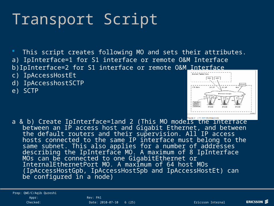
This script creates following MO and sets their attributes.a) IpInterface=1 for S1 interface or remote O&M Interfaceb)IpInterface=2 for S1 interface or remote O&M Interfacec) IpAccessHostEtd) IpAccesshostSCTPe) SCTP
a & b) Create IpInterface=1and 2 (This MO models the interface between an IP access host and Gigabit Ethernet, and between the default routers and their supervision. All IP access hosts connected to the same IP interface must belong to the same subnet. This also applies for a number of addresses describing the IpInterface MO. A maximum of 8 IpInterface MOs can be connected to one GigabitEthernet or InternalEthernetPort MO. A maximum of 64 host MOs (IpAccessHostGpb, IpAccessHostSpb and IpAccessHostEt) can be configured in a node)

Top right corner for field-mark, customer or partner logotypes. See Best practice for example.
Slide title 40 pt
Slide subtitle 24 pt
Text 24 pt
Bullets level 2-520 pt
Prep: QWE/C/Aqib Qureshi
Appr:
Checked:
Rev: PA1
Date: 2010-07-10 Ericsson Internal7 (25)
Transport Script Following attributes are seti) networkPrefixLength is the subnet maskii) defaultRouter0 is the IP Address of Default Router which can be either
O&M or S1. defaultRouter0 address cannot be 0.0.0.0. If the address of the defaultRouter0 is changed, it has to belong to the subnet defined by the networkPrefixLength and attribute rps must be set to false
iii) ownIpAddressActive is the IP Address of RPS (Router Path Supervision) on the active link (where traffic is handled). This IP Address must be set if RPS(Boolean)=True and can be shared with host that connect to IpHostLink.
iv) ownIpAddressPassive is the IP Address of RPS on passive link.v) Rps (Router Path Supervision) is done on the links defined by
ownIpAddressActive and ownIpAddressPassive, if they have valid IP addresses defined when they are created. It is possible to disable Router Path Supervision when the IpInterface MO has been created, by setting this attribute to false. If this attribute is set to false, the egress traffic is directed to defaultRouter0, which means that traffic disturbances will occur if the default router 0 is unavailable. Default=true
Top right corner for field-mark, customer or partner logotypes. See Best practice for example.
Slide title 40 pt
Slide subtitle 24 pt
Text 24 pt
Bullets level 2-520 pt
Prep: QWE/C/Aqib Qureshi
Appr:
Checked:
Rev: PA1
Date: 2010-07-10 Ericsson Internal8 (25)
Transport Scriptvi) vLan indicates whether VLAN tagging is used on this interface or
not. This attribute is applicable only when front ports are configured. That is, when one of the following conditions is fulfilled.
- This instance is related to a GigaBitEthernet MO, which has the attribute linkType set to FRONT_PORTS.
- - This instance is related to the InternalEthernetPort MO.(If this attribute is set to false, the Ethernet frames are untagged. If
this attribute is set to true, the Ethernet frames are tagged.)vii) Vid Integer is the assignment of VLan ID to IpInterface.Applicable only when vLan is set to true and when front ports are
configured, that is the attribute linkType of the GigaBitEthernet MO is set to FRONT_PORTS. Attribute has following possible values.
- vid 0 = with priority tag only- vid 1 - 4094 = with priority tag and vlan id

Top right corner for field-mark, customer or partner logotypes. See Best practice for example.
Slide title 40 pt
Slide subtitle 24 pt
Text 24 pt
Bullets level 2-520 pt
Prep: QWE/C/Aqib Qureshi
Appr:
Checked:
Rev: PA1
Date: 2010-07-10 Ericsson Internal9 (25)
Transport Scriptc) Create IpAccessHostEt which is IP Access Host,
executing on an ET board for IP. Only one IpAccessHostEt MO can be connected to one IpInterface MO on the same board.
i) ipAddress is the IP Address of S1 Interface.ii) Reference it to IpInterface MO that is carrying S1
Traffic. E.g., ipInterfaceMoRef Ref "ManagedElement=1,Equipment=1,Subrack=1,Slot=1,PlugInUnit=1,ExchangeTerminalIp=1,GigaBitEthernet=gbe-1,IpInterface=1"
iii) administrativeState indicates the state of this MO (Locked/Unlocked)

Top right corner for field-mark, customer or partner logotypes. See Best practice for example.
Slide title 40 pt
Slide subtitle 24 pt
Text 24 pt
Bullets level 2-520 pt
Prep: QWE/C/Aqib Qureshi
Appr:
Checked:
Rev: PA1
Date: 2010-07-10 Ericsson Internal10 (25)
Transport Script
d) IpAccessSctp (Streaming Control Transmission Protocol) MO is create. This MO is created for S1 interface. This MO represents an SCTP host. i) Referencing to IpAccessHostEt

Top right corner for field-mark, customer or partner logotypes. See Best practice for example.
Slide title 40 pt
Slide subtitle 24 pt
Text 24 pt
Bullets level 2-520 pt
Prep: QWE/C/Aqib Qureshi
Appr:
Checked:
Rev: PA1
Date: 2010-07-10 Ericsson Internal11 (25)
Transport Script
e) Create MO SCTP (Stream Control Transmission Protocol). This MO represents an SCTP host. SCTP transports signalling messages between SCTP users over IP networks
a) numberOfAssociations is the maximum no. of associations that this MO can handle (1…512).
b) References: - rpuId Ref “ManagedElement=1,SwManagement=1,ReliableProgramUniter=sctp_host“
- ipAccessSctpRef Ref "ManagedElement=1,IpSystem=1,IpAccessSctp=1“
- sctpRef Ref "ManagedElement=1,TransportNetwork=1,Sctp=1"

Top right corner for field-mark, customer or partner logotypes. See Best practice for example.
Slide title 40 pt
Slide subtitle 24 pt
Text 24 pt
Bullets level 2-520 pt
Prep: QWE/C/Aqib Qureshi
Appr:
Checked:
Rev: PA1
Date: 2010-07-10 Ericsson Internal12 (25)
Timing Unit Sync Reference TuSyncRef Script Create MO TuSyncRef. TuSyncRef MO administers a synchronization reference directly
connected to the board, where the Timing Unit (MO: TimingUnit) is located.
MO: TimingUnit represents a Timing Unit (reference clock) in the node.
In general, only one TuSyncRef instance can be created. For TUB2 boards, however, two instances can be created, and the following conditions apply:
i) the first TuSyncRef MO that is created on this board, is the external synchronization reference (1544 kHz, 2048 kHz or 10MHz)
ii) the second TuSyncRef MO that is created on this board, is the GPS synchronization reference

Top right corner for field-mark, customer or partner logotypes. See Best practice for example.
Slide title 40 pt
Slide subtitle 24 pt
Text 24 pt
Bullets level 2-520 pt
Prep: QWE/C/Aqib Qureshi
Appr:
Checked:
Rev: PA1
Date: 2010-07-10 Ericsson Internal13 (25)
Add Sync Ref Script
actionName addSyncRefResource: A network synchronization reference is registered with the action addSyncRefResource that associates the MO representing the reference to the Synchronization MO. At the same time, the priority of the reference is set.
This script associates "ManagedElement=1,TransportNetwork=1,Synchronization=1“ to Reference "ManagedElement=1,Equipment=1,Subrack=1,Slot=1,PlugInUnit=1,TimingUnit=1,TuSyncRef=1"

Top right corner for field-mark, customer or partner logotypes. See Best practice for example.
Slide title 40 pt
Slide subtitle 24 pt
Text 24 pt
Bullets level 2-520 pt
Prep: QWE/C/Aqib Qureshi
Appr:
Checked:
Rev: PA1
Date: 2010-07-10 Ericsson Internal14 (25)
Radio Create Script
Sets the AutoConfigurationAllowed MO to True. This attribute specifies if the system is allowed to auto create detected objects. Note that slots will always be auto created. When setting this attribute from true to false the system creates a new CV. Default=false
Create MO: SwAllocation for RULs. This MO defines a role for a PIU (In this case, RUL) inserted in a Slot. An SWA groups one or more repertoires together to form the role.
actionName addRepertoire: Adds the specifed repertoires to this list. If Repertoire already exist then this action is ignored.
Ref "ManagedElement=1,SwManagement=1,Repertoire=RBS_RU"

Top right corner for field-mark, customer or partner logotypes. See Best practice for example.
Slide title 40 pt
Slide subtitle 24 pt
Text 24 pt
Bullets level 2-520 pt
Prep: QWE/C/Aqib Qureshi
Appr:
Checked:
Rev: PA1
Date: 2010-07-10 Ericsson Internal15 (25)
Radio Create Script
Create RbsSubrack: This MO models an RBS subrack. Attributes define RbsSubrackId, cabinetPosition, noOfSlots and subrackPosition.
Create AuxPlugInUnit for RUL1,RUL2 and RUL3. Set proper RiPorts in DUL. RiPort MO represents a port on the DU
or the Radio where the Radio Interface (CPRI) cable is connected. It is used to connect a Radio to a DU or to another Radio.
Create MO called AntennaUnit under ManagedElement=1,Equipment=1,AntennaUnitGroup=1. This MO represents the physical AntennaUnit that contains several antenna subunits installed with a common mechanical tilt
Top right corner for field-mark, customer or partner logotypes. See Best practice for example.
Slide title 40 pt
Slide subtitle 24 pt
Text 24 pt
Bullets level 2-520 pt
Prep: QWE/C/Aqib Qureshi
Appr:
Checked:
Rev: PA1
Date: 2010-07-10 Ericsson Internal16 (25)
Radio Create Script Create MO RfBranch ( 1 & 2) under
ManagedElement=1,Equipment=1,AntennaUnitGroup=1. RfBranch MO represents the connection from an antenna feeder port on the RU to one antenna feeder connector on one or several antenna units. The MO represents all equipment between the radio and the antenna which isn't modelled by any other MO. That includes feeder, filters and non-supervised, non-controlled TMA
Set Attribute dLAttenuation under RfBranch. This attribute is the Downlink attenuation between the connector on the RU/RRU and the connector on the Antenna Unit. The attenuation includes feeder, filters and non-supervised, non-controlled TMA. The sequence contains 15 entries and each entry represents one 5 MHz interval. The first entry represents the attenuation value of the lowest frequency interval in the frequency band, and so on. The number of intervals depends on the frequency band. Unit: 0.1 dB

Top right corner for field-mark, customer or partner logotypes. See Best practice for example.
Slide title 40 pt
Slide subtitle 24 pt
Text 24 pt
Bullets level 2-520 pt
Prep: QWE/C/Aqib Qureshi
Appr:
Checked:
Rev: PA1
Date: 2010-07-10 Ericsson Internal17 (25)
Radio Create Script
Create MO AuPort 1 & 2 (Auxiliary Port) under ManagedElement=1,Equipment=1,AntennaUnitGroup=1,AntennaUnit=1,AntennaSubunit=1. This MO represents an antenna feeder port on the Antenna Unit where the antenna branch is connected.
Associating RfBranch=2 to rfPortRef (RUL1 and RUL2). Associating RfBranch=1 to auPortRef Auxiliary port 1. Associating RfBranch=2 to auPortRef Auxiliary port 2. Create MO SectorEquipmentFunction under ManagedElement=1.
This MO serves as a mapping between the cell and the RBS equipment used to provide coverage in a certain geographical area. The MO also controls the maximum output power of the sector.
Top right corner for field-mark, customer or partner logotypes. See Best practice for example.
Slide title 40 pt
Slide subtitle 24 pt
Text 24 pt
Bullets level 2-520 pt
Prep: QWE/C/Aqib Qureshi
Appr:
Checked:
Rev: PA1
Date: 2010-07-10 Ericsson Internal18 (25)
Cell and MME Configuration Script
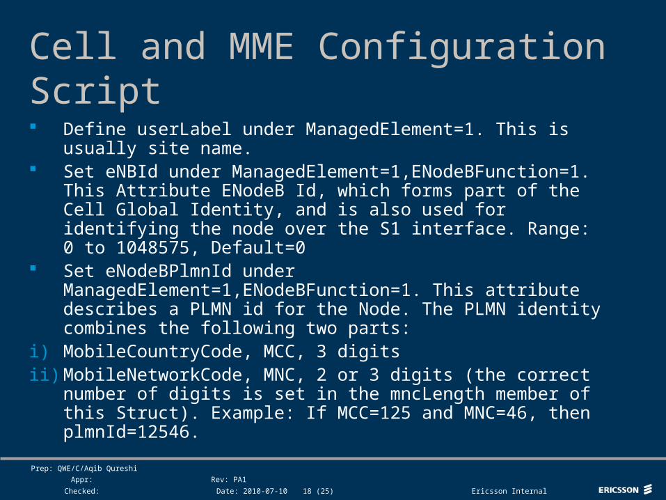
Define userLabel under ManagedElement=1. This is usually site name.
Set eNBId under ManagedElement=1,ENodeBFunction=1. This Attribute ENodeB Id, which forms part of the Cell Global Identity, and is also used for identifying the node over the S1 interface. Range: 0 to 1048575, Default=0
Set eNodeBPlmnId under ManagedElement=1,ENodeBFunction=1. This attribute describes a PLMN id for the Node. The PLMN identity combines the following two parts:
i) MobileCountryCode, MCC, 3 digitsii) MobileNetworkCode, MNC, 2 or 3 digits (the correct number of
digits is set in the mncLength member of this Struct). Example: If MCC=125 and MNC=46, then plmnId=12546.
Top right corner for field-mark, customer or partner logotypes. See Best practice for example.
Slide title 40 pt
Slide subtitle 24 pt
Text 24 pt
Bullets level 2-520 pt
Prep: QWE/C/Aqib Qureshi
Appr:
Checked:
Rev: PA1
Date: 2010-07-10 Ericsson Internal19 (25)
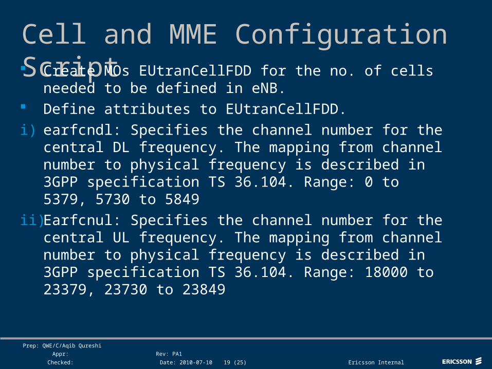
Cell and MME Configuration Script Create MOs EUtranCellFDD for the no. of cells
needed to be defined in eNB. Define attributes to EUtranCellFDD.
i) earfcndl: Specifies the channel number for the central DL frequency. The mapping from channel number to physical frequency is described in 3GPP specification TS 36.104. Range: 0 to 5379, 5730 to 5849
ii) Earfcnul: Specifies the channel number for the central UL frequency. The mapping from channel number to physical frequency is described in 3GPP specification TS 36.104. Range: 18000 to 23379, 23730 to 23849

Top right corner for field-mark, customer or partner logotypes. See Best practice for example.
Slide title 40 pt
Slide subtitle 24 pt
Text 24 pt
Bullets level 2-520 pt
Prep: QWE/C/Aqib Qureshi
Appr:
Checked:
Rev: PA1
Date: 2010-07-10 Ericsson Internal20 (25)
Cell and MME Configuration Scriptiii) CellId: RBS internal identity attribute for EUtranCell. This must be
unique in the RBS. Together with the Node ID and PLMN this will be a universally unique Cell ID. Range 0-255.
iv) physicalLayerCellIdGroup: This identities are grouped into 168 unique physical-layer cell-identity groups, each group containing 3 unique sub identities. This attribute identifies the group. This attribute together with physicalLayerSubCellId is used to calculate physical layer cell identity (see 36.211) which is sent as part of the system information (see 36.331). Range: 0 to 167
v) physicalLayerSubCellId: This attribute identifies the sub identity within the group. Range: 0 to 2
vi) TAC: (Tracking Area Code) The TAC part of a Tracking Area identity used in the radio network. Range: 0 to 16777215, Default=1

Top right corner for field-mark, customer or partner logotypes. See Best practice for example.
Slide title 40 pt
Slide subtitle 24 pt
Text 24 pt
Bullets level 2-520 pt
Prep: QWE/C/Aqib Qureshi
Appr:
Checked:
Rev: PA1
Date: 2010-07-10 Ericsson Internal21 (25)
Cell and MME Configuration Script
vii) bPlmnList: Describes a PLMN id for the Cell. The PLMN identity combines the following two parts:
a) MobileCountryCode, MCC, 3 digitsb) MobileNetworkCode, MNC, 2 or 3 digits (the correct number of
digits is set in the mncLength member of this Struct). Example: If MCC=125 and MNC=46, then plmnId=12546
Set noOfRxAntennas. The number of antennas that can be used for uplink beamforming/MIMO. Valid values: 0,1,2,4. 0 = Max number of antennas.
Set noOfTxAntennas. The number of antennas that can be used for downlink beamforming/MIMO. Valid values: 0,1,2,4. 0 = Max number of antennas.
Create MO TermPointToMme under ManagedElement=1,ENodeBFunction=1. This MO models the MME termination point of an S1 link between the RBS and the MME node. Assign Primary and Secondary IP Addresses to MME.
Top right corner for field-mark, customer or partner logotypes. See Best practice for example.
Slide title 40 pt
Slide subtitle 24 pt
Text 24 pt
Bullets level 2-520 pt
Prep: QWE/C/Aqib Qureshi
Appr:
Checked:
Rev: PA1
Date: 2010-07-10 Ericsson Internal22 (25)
Radio Create for additional cells Script
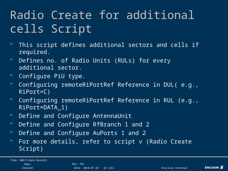
This script defines additional sectors and cells if required. Defines no. of Radio Units (RULs) for every additional sector. Configure PiU type. Configuring remoteRiPortRef Reference in DUL( e.g., RiPort=C) Configuring remoteRiPortRef Reference in RUL (e.g.,
RiPort=DATA_1) Define and Configure AntennaUnit Define and Configure RfBranch 1 and 2 Define and Configure AuPorts 1 and 2 For more details, refer to script v (Radio Create Script)

Top right corner for field-mark, customer or partner logotypes. See Best practice for example.
Slide title 40 pt
Slide subtitle 24 pt
Text 24 pt
Bullets level 2-520 pt
Prep: QWE/C/Aqib Qureshi
Appr:
Checked:
Rev: PA1
Date: 2010-07-10 Ericsson Internal23 (25)
Sector Create for additional cells Script
This script creates additional cells if required. Assigns attributes to each additional cell. For more details, refer to Script vi (Cell and MME
Configuration Script).

Top right corner for field-mark, customer or partner logotypes. See Best practice for example.
Slide title 40 pt
Slide subtitle 24 pt
Text 24 pt
Bullets level 2-520 pt
Prep: QWE/C/Aqib Qureshi
Appr:
Checked:
Rev: PA1
Date: 2010-07-10 Ericsson Internal24 (25)
Q & A

Top right corner for field-mark, customer or partner logotypes. See Best practice for example.
Slide title 40 pt
Slide subtitle 24 pt
Text 24 pt
Bullets level 2-520 pt
Prep: QWE/C/Aqib Qureshi
Appr:
Checked:
Rev: PA1
Date: 2010-07-10 Ericsson Internal25 (25)