enriching web applications with browser-to-browser...
TRANSCRIPT
Albert van der Linde
Licenciatura em Engenharia Informática
Enriching Web Applications withBrowser-to-Browser Communication
Dissertação para obtenção do Grau de Mestre em
Engenharia Informática
Orientador: Nuno Manuel Ribeiro Preguiça, Professor Associado,Universidade Nova de Lisboa
Co-orientador: João Leitão, Professor Auxiliar Convidado, Universi-dade Nova de Lisboa
Júri
Presidente: Doutora Margarida Paula Neves MamedeArguente: Doutor João Nuno de Oliveira e Silva
Vogal: Doutor João Carlos Antunes Leitão
Novembro, 2015

Enriching Web Applications with Browser-to-Browser Communication
Copyright © Albert van der Linde, Faculdade de Ciências e Tecnologia, Universidade
NOVA de Lisboa.
A Faculdade de Ciências e Tecnologia e a Universidade NOVA de Lisboa têm o direito,
perpétuo e sem limites geográficos, de arquivar e publicar esta dissertação através de
exemplares impressos reproduzidos em papel ou de forma digital, ou por qualquer outro
meio conhecido ou que venha a ser inventado, e de a divulgar através de repositórios
científicos e de admitir a sua cópia e distribuição com objetivos educacionais ou de inves-
tigação, não comerciais, desde que seja dado crédito ao autor e editor.
Este documento foi gerado utilizando o processador (pdf)LATEX, com base no template “unlthesis” [1] desenvolvido no Dep.Informática da FCT-NOVA [2]. [1] https://github.com/joaomlourenco/unlthesis [2] http://www.di.fct.unl.pt


To my family and friends.

Acknowledgements
I would like to thank my advisors, Prof. Dr. Nuno Preguiça and Dr. João Leitão, for
the opportunity to work with them on this project. Their encouragement and support
made this work possible. This work was partially supported by the projects FCT/MEC
NOVA LINCS PEst UID/ CEC/04516/2013 and the European project FP7 SyncFree (grant
agreement 609551), which I would like to thank for the grants given.
I want to mention the support from all my colleagues in the department. At last, I
would like to thank my mother, father, and sisters for their support, Marlene and my
friends for their motivation and patience.
vii

Abstract
An increasing number of web applications run totally, or partially, in client machines,
examples range from collaborative editing tools and social networks to multi-user games.
Although in many of these applications users interact among themselves, these applica-
tions continue to resort to an interaction model mediated through a centralized compo-
nent. This central component, besides being a contention point on which all interaction
between clients depends, can also introduce significative latency penalties specially for
clients that are geographically close (or even on the same local network).
We propose to enrich the current architecture used by most Web applications with
support for direct communication between browsers, improving latency among clients,
scalability of the centralized component, and offering the potential to support discon-
nected operation (from the centralized component). In this dissertation, we present the
design and implementation of a framework and supporting algorithms to allow clients to
efficiently communicate with each other in a peer-to-peer fashion, allowing applications
that execute in browsers to share replicas of objects across multiple instances of these
applications (on different browsers on different machines), which they can concurrently
modify and exchange among them.
Browsers propagate modifications directly using WebRTC, resorting to a server as
intermediate when WebRTC is unavailable. Replica state convergence is achieve using a
solution based on CRDTs.
We evaluate our implementation using both micro and macro benchmarks. The micro-
benchmarks evaluate specific parts of the system, namely a comparison between im-
plemented overlay networks and CRDT versions. The macro-benchmark compares the
performance of our prototype to an existing industrial product, in particular the Drive Re-
altime API offered by Google. The results show that our solution reduces latency between
geographically close clients and server load.
Keywords: client-based web applications; browser-to-browser; replication; CRDTs.
ix

Resumo
Um número crescente de aplicações web executam total, ou parcialmente, nas má-
quinas do cliente, como por exemplo ferramentas de edição colaborativa, redes sociais e
até jogos multi-utilizador. Embora em muitas destas aplicações os utilizadores interajam
entre si directa e continuamente, estas aplicações continuam a recorrer a um modelo de
interacção mediada por uma componente centralizada. Esta componente central, além de
ser um ponto de contenção para todas as interações entre os vários clientes, pode também
aumentar a latência de comunicação de forma significativa, especialmente entre clientes
que estão geograficamente próximos (ou até na mesma rede local).
Para contornar esta tendência, propomos enriquecer a arquitetura atual usada pela
maioria das aplicações Web, através da adição de suporte para comunicação direta en-
tre os browsers, melhorando a latência entre os clientes, a escalabilidade da componente
centralizada, e oferecendo suporte para a operação desconectada (da componente centra-
lizada). Nesta dissertação, apresentamos o desenho e a implementação de uma framework
e algoritmos de apoio para permitir aos clientes a possibilidade de comunicarem de forma
directa e eficiente (comunicação entre pares), permitindo que as aplicações que são execu-
tadas em vários browsers partilhem réplicas de objetos, que podem ser simultaneamente
modificadas e actualizadas através de comunicações par-a-par.
Os browsers propagam modificações diretamente usando WebRTC, recorrendo a um
servidor como intermediário quando o WebRTC não está disponível. A convergência do
estado das réplicas é alcançada usando uma solução baseada em CRDTs.
Foi feita uma avaliação da implementação usando micro e macro benchmarks. Os
micro-benchmarks avaliam partes específicas do sistema, nomeadamente, uma compara-
ção entre as várias redes sobrepostas implementadas e as diferentes versões de CRDTs. A
macro-benchmark compara o desempenho do nosso protótipo com uma solução indus-
trial existente, em particular, a Drive Realtime API oferecida pela Google. Os resultados
mostram que a nossa solução diminui a latência para cliente próximos geograficamente e
diminui a carga nos servidores.
Palavras-chave: aplicações-cliente baseadas em web; browser-to-browser; replicação; CRDTs.
xi

Contents
List of Figures xv
List of Tables xvii
Listings xix
1 Introduction 1
1.1 Motivation . . . . . . . . . . . . . . . . . . . . . . . . . . . . . . . . . . . . 2
1.2 Proposed Approach . . . . . . . . . . . . . . . . . . . . . . . . . . . . . . . 3
1.2.1 Main Contributions . . . . . . . . . . . . . . . . . . . . . . . . . . . 4
1.3 Document Organization . . . . . . . . . . . . . . . . . . . . . . . . . . . . 5
2 Related Work 7
2.1 Peer-to-peer systems . . . . . . . . . . . . . . . . . . . . . . . . . . . . . . . 7
2.1.1 Overlay Networks and Communication models . . . . . . . . . . . 8
2.1.2 Examples of peer-to-peer overlay networks . . . . . . . . . . . . . 10
2.2 Data Storage . . . . . . . . . . . . . . . . . . . . . . . . . . . . . . . . . . . 12
2.2.1 Conflict resolution techniques . . . . . . . . . . . . . . . . . . . . . 13
2.2.2 Examples of data storage systems . . . . . . . . . . . . . . . . . . . 15
2.3 Collaborative Editing . . . . . . . . . . . . . . . . . . . . . . . . . . . . . . 16
2.3.1 Handling concurrent updates . . . . . . . . . . . . . . . . . . . . . 17
2.3.2 Examples of collaborative editing systems . . . . . . . . . . . . . . 18
2.4 WebRTC . . . . . . . . . . . . . . . . . . . . . . . . . . . . . . . . . . . . . 20
2.4.1 Signalling . . . . . . . . . . . . . . . . . . . . . . . . . . . . . . . . 20
2.4.2 Examples of WebRTC enabled systems . . . . . . . . . . . . . . . . 21
2.5 Summary . . . . . . . . . . . . . . . . . . . . . . . . . . . . . . . . . . . . . 22
3 A Browser-to-browser Framework 23
3.1 Requirements . . . . . . . . . . . . . . . . . . . . . . . . . . . . . . . . . . 24
3.2 Interaction model . . . . . . . . . . . . . . . . . . . . . . . . . . . . . . . . 25
3.3 Architecture Overview . . . . . . . . . . . . . . . . . . . . . . . . . . . . . 28
3.3.1 B2BClient . . . . . . . . . . . . . . . . . . . . . . . . . . . . . . . . . 28
3.3.2 B2BServer . . . . . . . . . . . . . . . . . . . . . . . . . . . . . . . . 32
xiii
CONTENTS
4 Browser-to-browser interaction framework 35
4.1 Browser-to-Browser Communication . . . . . . . . . . . . . . . . . . . . . 35
4.1.1 Example . . . . . . . . . . . . . . . . . . . . . . . . . . . . . . . . . 37
4.2 Data Model . . . . . . . . . . . . . . . . . . . . . . . . . . . . . . . . . . . . 39
4.2.1 CvRDT . . . . . . . . . . . . . . . . . . . . . . . . . . . . . . . . . . 41
4.2.2 CmRDT . . . . . . . . . . . . . . . . . . . . . . . . . . . . . . . . . 44
4.3 Initialization and Parameters . . . . . . . . . . . . . . . . . . . . . . . . . . 48
4.3.1 Communication and Propagation Protocols . . . . . . . . . . . . . 48
4.3.2 Object Management Mechanisms . . . . . . . . . . . . . . . . . . . 50
4.3.3 Membership and Overlay Management Protocols . . . . . . . . . . 52
4.4 Server Setup . . . . . . . . . . . . . . . . . . . . . . . . . . . . . . . . . . . 56
4.5 Implementation Details . . . . . . . . . . . . . . . . . . . . . . . . . . . . . 57
5 Evaluation 59
5.1 Micro-Benchmarks . . . . . . . . . . . . . . . . . . . . . . . . . . . . . . . 59
5.1.1 Comparison on the usage of CvRDT and CmRDT . . . . . . . . . . 60
5.1.2 Impact of different overlay networks . . . . . . . . . . . . . . . . . 61
5.1.3 Random Graph Properties . . . . . . . . . . . . . . . . . . . . . . . 63
5.1.4 Support for disconnection and other execution environments . . . 65
5.2 Case Study: Google Drive Realtime API . . . . . . . . . . . . . . . . . . . 66
5.2.1 Design . . . . . . . . . . . . . . . . . . . . . . . . . . . . . . . . . . 66
5.2.2 Implementation . . . . . . . . . . . . . . . . . . . . . . . . . . . . . 67
5.2.3 Experimental Setup . . . . . . . . . . . . . . . . . . . . . . . . . . . 67
5.2.4 Latency . . . . . . . . . . . . . . . . . . . . . . . . . . . . . . . . . . 68
5.2.5 Bandwith . . . . . . . . . . . . . . . . . . . . . . . . . . . . . . . . . 69
6 Conclusion 73
6.1 Future Work . . . . . . . . . . . . . . . . . . . . . . . . . . . . . . . . . . . 74
Bibliography 77
A Appendix 1 81
xiv
List of Figures
2.1 WebRTC Signalling . . . . . . . . . . . . . . . . . . . . . . . . . . . . . . . . . 21
3.1 Communication model (client-server) | (browser-to-browser) . . . . . . . . . 23
3.2 Interaction overview of the proposed system . . . . . . . . . . . . . . . . . . . 26
3.3 Architecture . . . . . . . . . . . . . . . . . . . . . . . . . . . . . . . . . . . . . 29
4.1 API overview . . . . . . . . . . . . . . . . . . . . . . . . . . . . . . . . . . . . . 36
5.1 Message sizes of state and operation based propagation . . . . . . . . . . . . 60
5.2 Impact of compression . . . . . . . . . . . . . . . . . . . . . . . . . . . . . . . 61
5.3 Overlay network comparison . . . . . . . . . . . . . . . . . . . . . . . . . . . . 62
5.4 Random Graph Detail . . . . . . . . . . . . . . . . . . . . . . . . . . . . . . . . 63
5.5 Average Path Length and Diameter . . . . . . . . . . . . . . . . . . . . . . . . 64
5.6 Edge Count and Clustering Coefficient . . . . . . . . . . . . . . . . . . . . . . 65
5.7 Connection degree . . . . . . . . . . . . . . . . . . . . . . . . . . . . . . . . . . 65
5.8 Average Latency . . . . . . . . . . . . . . . . . . . . . . . . . . . . . . . . . . . 69
5.9 Latency: 95th percentile and maximum . . . . . . . . . . . . . . . . . . . . . 69
5.10 Server bandwidth usage . . . . . . . . . . . . . . . . . . . . . . . . . . . . . . 70
5.11 Client bandwidth usage . . . . . . . . . . . . . . . . . . . . . . . . . . . . . . . 71
xv

List of Tables
2.1 Browser Support for HTML APIs . . . . . . . . . . . . . . . . . . . . . . . . . 22
xvii

Listings
4.1 Communication interface . . . . . . . . . . . . . . . . . . . . . . . . . . . . 36
4.2 Example: Chat Room . . . . . . . . . . . . . . . . . . . . . . . . . . . . . . 39
4.3 Object Store Interface . . . . . . . . . . . . . . . . . . . . . . . . . . . . . . 39
4.4 Example: Object Usage . . . . . . . . . . . . . . . . . . . . . . . . . . . . . 41
4.5 CvRDT Interface . . . . . . . . . . . . . . . . . . . . . . . . . . . . . . . . . 42
4.6 Example: Last Writer Wins Register . . . . . . . . . . . . . . . . . . . . . . 44
4.7 CmRDT Interface . . . . . . . . . . . . . . . . . . . . . . . . . . . . . . . . 45
4.8 Example: Operation Based OR-Set . . . . . . . . . . . . . . . . . . . . . . . 47
4.9 Initialization and Parameters . . . . . . . . . . . . . . . . . . . . . . . . . . 48
4.10 Parameters on Messaging Mechanisms . . . . . . . . . . . . . . . . . . . . 50
4.11 Parameters on Object Propagation Mechanisms . . . . . . . . . . . . . . . 52
4.12 Parameters on Membership Mechanisms . . . . . . . . . . . . . . . . . . . 55
4.13 Peer-to-peer connectivity defaults . . . . . . . . . . . . . . . . . . . . . . . 55
5.1 "Listener" . . . . . . . . . . . . . . . . . . . . . . . . . . . . . . . . . . . . . 67
5.2 "Writer" . . . . . . . . . . . . . . . . . . . . . . . . . . . . . . . . . . . . . . 67
A.1 "JavaScript OR-Set Implementation" . . . . . . . . . . . . . . . . . . . . . . 81
xix

Chapter
1Introduction
In recent years we have observed the proliferation and increase in popularity of web
applications. A lot of these applications are centered on users, and many have aspects
of collaborative editing or support for direct interaction between their users. Relevant
examples of these applications are social networks, chat systems, games, and collaborative
editing systems like Google Docs or Microsoft Office 365.
This increase in popularity has also led to the increase of the complexity of web
based applications. Recent changes in web browsers and client devices have enabled pro-
grammers to build more powerful and interesting web applications. From collaborative
editing tools to multi-user games, an increasing number of web applications run partially,
or completely, on client machines. Recent frameworks and developer APIs for browser
applications allow for easy development and deployment of such applications. The rise
of HTML5[41] has paved the way for even more complex and interesting applications
by providing additional control over the browser to developers, including aspects such
as multi-threading and local storage, which previously were available only to desktop
applications. This creates the opportunity for richer client browser applications to be
developed.
Currently, even when web applications run in the client, they typically access informa-
tion stored in servers (potentially in datacenters) and all communication between clients
goes through this centralized component - e.g. all interaction in the Google Docs applica-
tion is mediated by a server even when clients are nearby. The growth in browser support
for WebRTC[42] (which allows for peer-to-peer like communication between browsers)
makes a good promise for enabling client browser fully distributed architectures, moving
from the client-server model to a server-to-server (or in this case, browser-to-browser)
model.
Peer-to-peer systems have gained a lot of attention in research and have been widely
1
CHAPTER 1. INTRODUCTION
adopted by industry. Peer-to-peer has been adapted for supporting file-sharing, streaming
media, telephony, and even volunteer computing platforms and applications[27]. Peer-to-
peer technologies have also been incorporated into other systems, for example Amazon’s
Dynamo[9], a NoSQL database that uses a DHT (discussed in Section 2.1.1) to distribute
state over nodes as if it were a distributed hash table.
There are still few examples of frameworks that employ peer-to-peer techniques to
improve web applications running in the clients. By moving significant parts of an ap-
plication’s logic to the client side in browsers and leveraging peer-to-peer (using recent
browser based technologies) architectures (which are widely explored by academia and
industry), powerful applications can be conceived.
In this work, we propose a framework to simplify the creation of such applications that
follow this new paradigm. We further implemented and experimented with a prototype
of this framework which acts as a proof of concept for our proposal.
1.1 Motivation
Real-time collaborative editing tools, where users can edit the same file simultaneously,
have been deployed with significant client adoption. Current collaborative editing ap-
plications and developer frameworks are typically based the client-server model, with
only a limited number of applications and frameworks resorting to peer-to-peer support
at the browser level. User count can drastically increase in a short span of time and the
user’s need for fast propagation of updates (i.e., low latency between clients) has greatly
increased over the last years as higher expectations are put on web applications. Collabo-
rative editing is thus a good example of an application that can be greatly improved by
exploring this design space.
In the current interaction model servers act as the data storage system, maintaining
the data being edited, while also being used for access control and to expose, or resolve,
divergence on concurrently edited objects.
The limitations to the client-server model are well-known and include: i) a significant
increase in client-to-client latency, especially between those clients that are geographically
close (or even those on a single local network); ii) the centralized component is a potential
contention point that can limit the scalability due to limits on available resources (which
cloud computing mitigates as we will address next); iii) the server is a single point of
failure that prevents any interaction among users when the server becomes unavailable
(i.e., if the server becomes unavailable the whole system becomes unavailable).
The rise of cloud computing mitigated significantly some of these limitations, espe-
cially scalability and fault tolerance, as techniques like replication can be used (i.e., the
ability to increase the amount of servers that support an application according to load,
typically using partitioning techniques). On the other hand, using cloud infrastructures
adds monetary costs to application providers which is obviously undesirable or even
2
1.2. PROPOSED APPROACH
poses a practical impediment for the operation in the case of small companies that try to
launch an application in an already very competitive market.
Current frameworks for collaborative editing on the web[11, 15, 17] do not allow
direct client-to-client (i.e, peer-to-peer) communication, and all user interactions are
mediated by the central component. The main reasons for this are the following. First,
relying on a central component simplifies the management of data and notifications
to clients. Second, limitations to peer-to-peer networking in browsers made it hard to
explore the peer-to-peer paradigm (as discussed previously) in the past. However, a
number of recent developments are challenging these problems.
CRDTs[36, 37], Convergent (or Commutative) Replicated Data Types, allow for auto-
matic reconciliation of state even in decentralized systems. Operations on CRDTs can
immediately execute locally and, unaffected by network latency, faults, or disconnec-
tions, data replicas will eventually converge towards a common, single, state where these
replicas are able to synchronize and updates are propagated across all replicas. This
makes managing replicated data much simpler, as convergence of state no longer has to
be ensured by application logic.
Regarding support for peer-to-peer networking, a number of new technologies have
been introduced in browsers recently. These technologies incude WebRTC[42] (Web Real
Time Communication), and the proposal of protocols (and publicly available services)
to surpass firewall and NATs like STUN[18] and TURN[19]. These new technologies
combined with advances of HTML5, pave the way to the development of frameworks that
allow for enriching web applications with direct communication between user devices.
Using peer-to-peer for collaborative editing or other multi-user applications (i.e., so-
cial networks, games, and others) that have high user interaction in real-time can greatly
reduce client-to-client latency and the load on the server as fewer server accesses might
be needed. Ideally, scalability can be greatly increased and user experience improved.
Other recent improvements also contribute to the possibility of a system such as we
propose (though not being fundamentally required). Improvements on local storage
and threading support make it possible for objects to be cached or even permanently
stored on the client, possibly removing the need for continuous access to the server, as to
reduce access latency and bandwidth, server load or even reducing trust on the service
provider[43].
1.2 Proposed Approach
To overcome the current limitations of centralized architectures, in this thesis we pro-
pose to enrich current web application architectures with support for direct browser-to-
browser communication.
We diverge from the common model for designing web applications, and propose a
technique that enriches cloud infrastructures with peer-to-peer techniques adapted for
web-applications enviroments, to surpass the client-server model’s limitations. The use
3
CHAPTER 1. INTRODUCTION
of this enriched model has the potential to impact scalability and availability of web
applications, latency experienced by geographically close clients, and operational cost for
the operation of web application’s centralized components.
To achieve this, we present the design of a framework that allows for applications
executing on multiple browsers to keep up-to-date replicas of a set of objects which can
be modified concurrently. This framework, which we have implemented as a prototype,
is composed by the following main components: i) mechanisms for managing browser-to-
browser connections that allow instances of a web application, according to some policy
defined by that application, to establish direct connections between users that interact fre-
quently and/or are geographically close; ii) a set of communication primitives that allow
applications to share data by using browser-to-browser connections, and to coordinate
between each other as to propagate information to the centralized component for both
durability and also to enable the exchange of information with users that must access
the application exclusively via the centralized component, due to the lack of WebRTC
support of their browser, or due to overly restrictive networking policies; iii) mechanisms
that enable the replication of shared objects, with updates being transparently propa-
gated across all clients, guaranteeing that application state eventually converges; iv) a
library of CRDTs with support for these mechanisms, written in JavaScript, based on the
specifications in [36]. This simplifies the design and implementation of decentralized
web applications that execute on the browser.
1.2.1 Main Contributions
The main contributions of this thesis are the following:
• A framework supporting direct browser-to-browser communication, without the
need to install any kind of software or browser plugins.
• The design and implementation of a mechanism to replicate a set of objects in web
applications, combining peer-to-peer interactions and a centralized component.
• A CRDT library that can be used with the replication mechanism for maintaining
the state of different applications.
• An evaluation of the proposed system and comparison with an existing industry
solution.
The design of our system’s programmer interface was performed with close attention
to existing frameworks’ APIs. Besides the fact that such an approach enables existing
applications to be easily converted to our solution, it enables us to compare our proposed
solution to one that only uses the central component for communication, i.e., a client-
server model.
4
1.3. DOCUMENT ORGANIZATION
The system we present in this thesis exposes a programmer interface for creating
applications with similarities to the PeerJS API and other messaging systems (like pub-lish/subscribe) for interaction based on sending messages. We combine this interface with
an interface similar to the Google Drive Realtime API[17] for object replication and syn-
chronization.
To evaluate the performance of our implementation we developed micro and macro
benchmarks. The micro-benchmarks evaluate specific parts of the system, namely a
comparison between implemented overlay networks and CRDTs. The macro-benchmark
was created to compare the performance of our prototype to an existing industry solution,
namely the Drive Realtime API offered by google. We show that we are able to improve
on the total server load and on latency felt by clients.
Publications
Part of the results in this thesis were published in the following publication:
Enriquecimento de plataformas web colaborativas com comunicação browser-a-
browser Albert Linde, João Leitão e Nuno Preguiça. Actas do sétimo Simpósio de In-
formática, Covilhã, Portugal, September, 2015
1.3 Document Organization
The remainder of the thesis is organized as follows:
Chapter 2 introduces fundamental concepts which are relevant for the context of the
contributions presented in the thesis;
Chapter 3 presents the design of such a system as we propose in this thesis;
Chapter 4 describes how the prototype built can be used and also discusses relevant
implementation details;
Chapter 5 presents the evaluation of our system and the results of comparison estab-
lished industry solution;
Chapter 6 concludes this thesis by summarizing the thesis and discussing pointers for
future work.
5

Chapter
2Related Work
This thesis addresses the challenges of real-time collaboration leveraging on peer-to-peer
communication directly on the browser. Therefore, various aspects have to be considered.
The following sections cover the main aspects of these fields, in particular:
In Section 2.1 existing peer-to-peer technologies are studied and compared, with special
interest on overlay networks and communication models.
In Section 2.2 web based service providers are discussed, in particular addressing the
challenge of storing and accessing data.
In Section 2.3 the field of collaborative editing is explored, with emphasis on real-time
collaborative editing.
In Section 2.4 we give an overview of the existing WebRTC standard, which serves as a
basis for our work.
2.1 Peer-to-peer systems
Peer-to-peer systems typically have a high degree of decentralization, leveraging the use
of resources from the server to the client. In other words, each peer implements both
server and client functionality to distribute bandwidth, computation, and storage across
all participants of a distributed system[27]. This is achieved by allocating state and tasks
among peers with few, if any, dedicated peers.
Nodes are initially introduced to the system and typically little or no manual con-
figuration is needed to maintain connectivity1. Participating nodes generally belong to
independent individuals who voluntarily join the system and are not controlled by a
single organization.
1To consider a network as connected, there should be at least one path from each node to all other nodes.
7
CHAPTER 2. RELATED WORK
Peer-to-peer systems are interesting due to their low barrier to deployment, its organic
growth (as more nodes join, more resources are available), resilience to faults/malicious
attacks, and the abundance/diversity of systems.
Popular peer-to-peer applications include sharing and distribution of files, streaming
media, telephony, and volunteer computing. Peer-to-peer technologies were also used
to create a diversity of other applications, for example Amazon Dynamo[9] which is a
storage system, which internally heavily relies on DHTs, demonstrating the benefits of
leveraging peer-to-peer architectures. It is important to note that the network topology
of the underlying network has a high impact on the performance of peer-to-peer services
and applications. For client nodes to be able to cooperate they need to be aware of the
underlying network. The typical approach is to create a logical network of nodes on top
of the underlying network, called an overlay network.
Thus, in order to develop a peer-to-peer distributed service, it is of paramount rele-
vance to study the mechanisms for creating and managing overlay networks that match
the application requirements.
2.1.1 Overlay Networks and Communication models
An overlay network is a logical network of nodes, built on top of another network. Links
between nodes in the overlay network are virtual links, being composed of various links
of the underlying network. In peer-to-peer systems, overlay networks are constructed on
top of the internet, each link being a connection between two peers.
To achieve an efficient and robust method of delivering data through a peer-to-peer
technique an adequate overlay network is needed. When building an application, the
programmer must first decide on the overlay to deploy and use, choosing between degrees
of centralization as well as on structured vs unstructured designs.
Degree of centralization: Peer-to-peer networks can be classified by their use of cen-
tralised components.
Partly centralized networks leverage system components to dedicated nodes or a
central server to control and index available resources. These centralised com-
ponents are used to coordinate system connections, facilitate the establishment
of communication patters, and coordinate node co-operation.
As an example, when client nodes want to execute a specific query, only the
central component is contacted, which in turn can return the set of nodes that
match the query. These systems are relatively simple to build but come with
the drawback of a potential single point of failure and bottleneck. Therefore,
this design can not be as resilient and scalable as a fully decentralized system.
Examples include Napster[28], Bittorrent using trackers[5], BOINC[1], and
Skype[2].
8
2.1. PEER-TO-PEER SYSTEMS
Decentralized networks avoid the use of dedicated nodes. All network and com-
munication management is done locally by each participating node, using light
coordination mechanisms. This way a singe bottleneck and point of failure is
avoided, increasing potential for scalability and resilience.
In this type of architecture, nevertheless, a few selected nodes may act as su-
pernodes, as to leverage potential higher CPU or bandwidth available, gaining
additional responsibilities such as storing state or even becoming the entry
point for new nodes. As queries cannot be sent to and executed by a cen-
tral component, typically when using unstructured overlays they have to be
flooded through the network or routed through the network when using a
structured overlay. Example protocols include Gnutella[38] and Gossip[3].
Structured vs Unstructured: Choosing between structured and unstructured overlays
depends mostly on the usefulness of key-based routing algorithms2 and the amount
of churn3 that the system is expected to be exposed to.
Structured overlays: Each node gets an identifier which determines its position in
the overlay structure. Identifiers are chosen in a way that peers are usually
uniformly distributed at random over the key space. This allows to create a
structure similar to a hash table, named DHT, distributed hast table. This
type of overlay graph is typically chosen when efficient (logarithmic complex-
ity) key-based routing is required. Structured overlays typically use more
resources to maintain the overlay, but in return get efficient queries at the cost
of poor performance when churn is high, in fact, churn is not handled well at
all.
Unstructured overlays: There is no particular structure in the network links and
queries are usually done by flooding the network. Each peer keeps a local index
of its own resources and, in some cases, the resources of its neighbours. The
connected peers are designated as a partial view. This is a (small) fraction of all
peers in the system with whom that participant can interact directly. Ideally,
the size of such partial views should grow logarithmically with the number
of participants in the system. Queries are typically disseminated among the
connected peers. To ensure that a query returns all possible results, the query
must be disseminated to all participants.
Maintaining data: In partially centralized systems data is typically stored at the insert-
ing and downloading nodes. The central component maintains metadata, i.e., an
index, on the stored data including where it is located.
2Key-based routing is a lookup method, used in conjunction with distributed hash tables, that enablesto find the node that has the closest identifier to the key being searched.
3Churn is the participant turnover in the network (the amount of nodes joining and leaving the systemper unit of time).
9
CHAPTER 2. RELATED WORK
In unstructured systems data is also stored on submitting and downloading nodes
but to locate data typically the queries are flooded. For faster searches, nodes can
distribute metadata among neighbours.
In structured overlays distributed state is maintained using distributed hash tables.
Primitives are similar to any hash table, and easily implemented when a key-based
routing function is available. On high churn it becomes very inefficient to store large
amounts of data at peers responsible for the keys, therefore indirection pointers are
commonly used, pointing to the node (or nodes) that effectively holds the data.
Coordination: In partially centralized systems the centralized component can trivially
achieve coordination.
In unstructured overlays, epidemic techniques are typically used because of their
simplicity and robustness to churn. Information tends to propagate slowly though
and scaling to large overlays is costly. Spanning trees4 can increase efficiency but
maintaining the tree structure adds maintenance costs.
In structured overlays, key-based routing trees are the basis for potentially large
sub-groups within the overlay, enabling fast coordination and good efficiency.
2.1.2 Examples of peer-to-peer overlay networks
Chord[39] is a distributed lookup protocol that enables peer-to-peer systems to effi-
ciently locate nodes that store a particular data item. It only offers one primitive:
given a key, return the nodes responsible for the key. Keys are distributed over
the nodes using consistent hashing and replicated over succeeding nodes. Nodes
typically store their successor nodes, forming an ordered ring (considering node’s
identifiers), making it easy to reason about the overlay structure. For fault-tolerance
a list of successor nodes is kept and for efficient lookups a finger table, shortcuts to
nodes over the graph, is used to jump over nodes in the graph.
Gnutella[38] is a decentralized peer-to-peer file sharing protocol. When a node is boot-
strapping to the network, it tries to connect to the nodes it was shipped with, as
well as nodes it receives from other clients. It connects to only a small amount of
nodes, locally caching the addresses it has not yet tried, discarding the addresses
that are invalid.
Queries are issued and flooded from the client to all actively connected nodes, the
query is then forwarded to any nodes they know about. Forwarding ends if the
request can be answered or the Time-To-Live field ends. The protocol in theory
doesn’t scale well, as each query increases network traffic exponentially each hop,
while being very unreliable as each node is a regular computer user, constantly
connecting and disconnecting.
4A spanning tree of a graph is a tree connecting all nodes in the graph.
10
2.1. PEER-TO-PEER SYSTEMS
A revised version of the gnutella protocol is a network made of leaf nodes and ultra
peers. Each leaf node is connected to a small number of ultra peers, while ultra
peers connect to many leaf nodes and ultra peers. Leaf nodes send a table containing
hashed keywords to their ultra peers, which merge all received tables. These tables
are distributed among ultra peer neighbours and used for query routing, by hashing
the query keywords and trying to match the tables.
Cyclon[40] is a membership management framework for large peer-to-peer overlays.
The used membership protocol maintains a fixed length partial view managed
through a cyclic strategy. This partial view is updated every T time units by each
node though an operation called shuffle. In a shuffle, a node selects the oldest node
in its partial view and exchanges some elements of its local partial view with it.
When nodes initially join the overlay a random walk is used, ensuring that the in-
degree of all nodes remains balanced. This work achieves an overlay topology with
low diameter and low clustering coefficient with highly symmetric node degrees
and high resilience to node failures.
Scamp[14] is a membership management framework for large peer-to-peer overlays. The
Scamp protocol maintains two views, a PartialView to send gossip messages and an
InView from which they receive messages. The PartialView is not of fixed length, it
grows to a size logarithmic in scale to the number of nodes in the network without
any node being aware of this number. The protocol uses a reactive strategy, in
the sense that the partial views are updated when nodes join or leave the system.
Periodically nodes send heartbeat messages as to detect and recover from isolation
due to failures. Not receiving any heartbeats allows the node to assume that it is
isolated, triggering the join mechanism to effectively rejoin the overlay.
HyParView[25] , Hybrid Partial View, is a reliable gossip-based broadcast protocol that
maintains a small symmetric Active View (managed through a reactive strategy)
for broadcasts and a larger Passive View (managed through a cyclic strategy) to
recover timely from faults. Both strategies are very similar to Scamp and Cyclon.
TCP is used as a reliable transport and to detect failures, being feasible as the Active
View is small. Even with a small ActiveView, improving protocol efficiency as less
network traffic is required for flooding messages, very good results in reliability are
obtained. This work shows the importance of each reactive and cyclic strategies to
maintain views of the network, and that the use of a reliable transport mechanism,
like TCP, to timely encounter failures, can greatly improve results.
Using a structured network overlay as Chord, a really high network efficiency can
be achieved as all request are routed directly to the right nodes. Unstructured network
overlays typically have to flood the network, reducing efficiency, but create tolerance to
network churn. Declaring some nodes as dedicated to the network, as done by Gnutella,
11
CHAPTER 2. RELATED WORK
can greatly reduce network traffic. Cyclon, Scamp, and HyParView each show the im-
portance of reactive and cyclic strategies for maintaining partial views as well as the
combination of both.
2.2 Data Storage
Web based services store client data on geographically distributed data-centers, trying to
provide good latency, bandwidth, and availability for interactions with the data. Typi-
cally replication and distribution of state across geographically separated data centres is
required to ensure low latency and fault tolerance. A problem arises, formally captured
by the CAP theorem[16], which states that it is impossible for a distributed computer
system to simultaneously provide all three of the following: Consistency (all nodes see
the same data at the same time), Availability (every request receives a response about
whether it succeeded or not) and Partition tolerance (the system continues to operate
despite arbitrary message loss or partial failure of the system or unavailability due to
network partitions). Unfortunately, due to how the internet works, partitions due to
network or node failures are part of our lives so the question is to ask which to sacrifice,
Consistency or Availability?
Strong Consistency. A system is said to provide strong consistency if all accesses to data
are seen by all clients in the same order (sequentially). A distributed system pro-
viding Strong Consistency will come to a halt if nodes become network-partitioned.
It is easy to understand that two nodes cannot decide on a value if they cannot
reach one another. Consistency can thus be maintained but the system will sacrifice
Availability.
Eventual Consistency is a consistency model used in distributed computing systems to
achieve high availability which informally guarantees that, if no new updates are
made to a given data item, eventually all accesses to that item will return the value
of the last update. This allows these systems to, even during network partitions,
always serve read and write operations over data. Eventual consistency may not be
enough, one example: user A writes to a page and user B answers, due to network
latencies user C sees B’s answer before A’s initial post. This shows that while this
consistency model is correct, it can lead to confusion.
Causal Consistency. A system provides causal consistency if potentially causally related
operations are seen by every node of the system in an order that respects these
causal dependencies. Concurrent writes (i.e., write operations that are not causally
related) may be seen in different orders by different nodes. When a node performs
a read followed later by a write, even on different objects, the first operation is said
to be causally ordered before the second, because the value stored by the write may
have been dependent upon the result of the read. Also, even two write operations
12
2.2. DATA STORAGE
performed by the same node are defined to be causally related, in the order they
were performed. Intuitively, returning on our previous example, such a system
would never show B’s updates before A’s as they are causally related.
Using eventual and causal consistency (i.e., not strong consistency) usually comes
with a cost: state divergence. To address state divergence, conflict resolution techniques
such as the ones discussed in section 2.2.1 must be used.
One way to avoid state divergence, as achieved in Yahoo!’s PNUTS[6], is to funnel all
state changing operations through a per record chosen primary site and lazily propagating
to replicating nodes. This increases latency and reads can return stale data, but data
exposed to users is consistent. The problem of this approach is availability as the primary
site is a potential single point of failure.
When multiple nodes can write to the same data, object versioning control has to be
done using for example logical clocks or version vectors[22, 31] and conflict resolution
techniques have to be applied.
2.2.1 Conflict resolution techniques
Relaxing from a strong consistency model to a weaker model such as causal consistency,
minimizes the amount of required synchronization among replicas at the expense of
having to deal with state divergence. To do so, one resorts to conflict resolution techniques.
Common conflict resolution techniques include:
Last Writer Wins: the idea is that the last write based on a node’s system clock will
overwrite an older one. Using a single server this is trivial to implement but when
clocks are out of synch when writing on multiple nodes, choosing a write between
concurrent writes is not trivial at all and can lead to lost updates.
Programatic Merge: letting the programmer decide what to do when conflicts arise. As
an example, an application maintaining shopping carts can choose to merge the
conflicting versions by returning a single unified cart. This conflict resolution tech-
nique requires replicas to be instrumented with a merge procedure, or alternatively,
requires replicas to expose diverging states to the client application which then
reconciles and writes a new value.
Commutative Operations: If all operations are commutative, conflicts can easily be
solved. Independently of the order, when all operations have been received (and ap-
plied), the final outcome will be the same. An always incrementing counter, where
each operation is uniquely marked by the writing node, is an easy example: inde-
pendently of the order of operations, the final result will eventually be the same.
Commonly used commutative operation techniques are:
OT, Operational Transformation. The idea of OT is to transform the parameters
of an operation to the effects of previously executed concurrent operations,
13
CHAPTER 2. RELATED WORK
so that the outcome is always consistent. As an example, a text document
contains ’abc’ and there are two concurrently editing users. One user inserts
’x’ at position 0 and the other deletes ’c’ from position 2. If both execute their
operation and later receive the operation of the other (due to network latency),
the final states diverge to ’xac’ and ’xab’. Transforming the operations solves
this problem, the delete is transformed to increment one position and the
insert can remain the same. Both outcomes become ’xab’, independently of the
order in which operations are applied.
Operational Transformation has been extensively studied, especially by the
concurrent editing community, and many OT algorithms have been proposed.
However, it was demonstrated that most OT algorithms proposed for a decen-
tralized architecture are incorrect[30]. It is believed that designing data types
for commutativity is both cleaner and simpler[36].
CRDT, Convergent or Commutative Replicated Data Types. CRDTs are replicated
data types that guarantee eventual consistency while being very scalable and
fault-tolerant. An example is a replicated counter, which converges because in-
crement and decrement operations commute. No synchronization is required
to ensure convergence, so updates always execute locally and immediately, un-
affected by network latency, faults, or disconnections. CRDTs can typically be
divided in two classes:
CvRDT, state-based Convergent Replicated Data Types. In the state-based
class, the successive states of an object should form a monotonic semi-
lattice5 and replica merge computes a least upper bound. In other words,
when merging diverging states the end result must be equal at each replica.
State-based CRDTs require only eventual communication between pairs
of replicas.
CmRDT, operation-based Commutative Replicated Data Types. In the opera-
tion-based class, concurrent operations commute. Operation-based repli-
cation requires reliable broadcast communication with delivery in a well-
defined order, such as a causal order between operations.
Both classes of CRDTs are guaranteed to eventually converge towards a com-
mon, single, state (i.e., when all updates are received by all participating
nodes). Practical use of CRDTs shows that they tend to become inefficient
over time, as tombstones accumulate and internal data structures become un-
balanced[36]. Garbage collection can be performed using a weak form of
synchronization, outside of the critical path of client-level operations.
5An idempotent and commutative system that grows only in one direction.
14
2.2. DATA STORAGE
2.2.2 Examples of data storage systems
Spanner[7] is a system providing strong consistency which uses the Paxos algorithm as
part of its operation to replicate data across hundreds of data-centers. It also makes
heavy use of hardware-assisted time synchronization using GPS clocks and atomic
clocks to ensure global consistency.
One server replica is elected as the Paxos leader for a replica group, which will
become the entry point for all transactional activity for that group. Groups may
include read-only replicas, which do not vote in the Paxos algorithm and cannot
become group leaders.
Furthermore all transactions in Spanner are globally ordered as they are assigned
a hardware assisted commit timestamp. These timestamps are used to provide
multi-versioned consistent reads without the need for taking locks. A global safe
timestamp is used to ensure that reads at the timestamp can run at any replica and
never block behind running transactions.
Spanner thus has very strong consistency and timestamp semantics, providing scal-
able data storage and synchronous replication.
Dynamo[9] is a highly-available key-value storage system. To achieve high availability,
consistency is sacrificed using object versioning and application-assisted conflict
resolution, exposing data consistency issues and reconciliation logic to the develop-
ers.
Data is partitioned and replicated using consistent hashing and vector clocks are
used for object versioning. Dynamo uses a gossip based failure detection and mem-
bership protocol. This removes the need for manual configuration creating a com-
pletely decentralized system, ensuring that adding and removing nodes can be done
without any manual effort. Each node is aware of the data being hosted at its peers.
In contrast to other DHT systems, each node actively gossips the full routing table
with other nodes in the system. This model works well in their expected scenario
of a couple of hundred of nodes, scaling this design to a higher number of nodes
can be troublesome as the routing table increases with the number of nodes in the
system.
Gemini and its RedBlue consistency[26] build on the premise that while a system can
be leveraged to use eventual consistency for higher performance, strong consistency
may be necessary to ensure correctness of the applications.
RedBlue consistency labels operations as red or blue. Blue operations are to be fast
(eventually consistent) while red operations are slow (strongly consistent). Blue is
used when possible and red when needed. Gemini is a coordination infrastructure
implementing RedBlue consistency. Experimental results show that RedBlue con-
sistency provides substantial performance while being able to maintain application
15
CHAPTER 2. RELATED WORK
invariants, the downside is that transactions have to be individually modified and
correctly labelled.
Riak[21] is a distributed NoSQL key-value data store that supports high availability
by giving the possibility between strong and eventual consistency, using quorum
read and write requests and multi-version concurrency control with vector clocks.
Eventual consistency in Riak uses CRDTs at its core, including counters, sets, flags,
registers, and maps. Partitioning and replication is done via consistent hashing
using a masterless approach, thus providing fault-tolerance and scalability. The
built-in functions determine how replicas distribute the data evenly, making it easy
for the developer to scale out to more nodes.
SwiftCloud[34] is an eventual consistency data storage system with low latency that
relies on CRDTs to maintain client caches. The main focus of this work is to integrate
client and server-side storage. Responsiveness is improved when accessed objects
are locally available at the cache, which allows for disconnected operation.
In the presence of infrastructure faults, a client-assisted failover solution allows
client execution to resume immediately and seamlessly access consistent snapshots
without blocking. Additionally, the system supports merge-able and strongly con-
sistent transactions that target either client or server replicas and provide access to
causally-consistent snapshots efficiently.
Systems like Spanner have been designed to provide strong consistency on geograph-
ically distributed data-centers. These systems use very complicated algorithms or spe-
cialised underlying hardware and are not trivial to deploy. Systems supporting weaker
consistency models have been developed, like Dynamo, that support writes on different
clients increasing scalability and fault tolerance, but need a way to address state diver-
gence. A system like Gemini that supports both eventual and strong consistency can
be used to have the best of both. It can be very difficult to reason in detail on such a
system, especially on what has to be strong or what can be eventually consistent. The use
of CRDTs, like in Riak and SwiftCloud, can greatly improve latency as all updates can
always execute and merging diverging state isn’t an issue, as data converges to a single
final consistent state.
2.3 Collaborative Editing
A collaborative editor is a piece of software that allows several people to edit files using dif-
ferent client-devices, working together through individual contributions. Collaborative
editing can be divided in two types: real-time and non-real-time. In real-time collabora-
tive editing systems users can edit the same file simultaneously while in non-real-time
collaborative editing systems editing the same file at the same time is not allowed.
16
2.3. COLLABORATIVE EDITING
In collaborative editing the main challenge is to figure out how to apply edits from
remote users, who produced these edits on versions of the document that possibly never
existed locally, and that can potentially conflict with the user’s own edits. Users may
write on previously decided sub-parts of the document, facilitating merges, or, on the
other end of the spectrum, work together on the same task.
2.3.1 Handling concurrent updates
There are several approaches in creating a collaborative editor. The basic needs for such
a system are the possibility for concurrent (possibly in real time) editing of objects while
preserving user intent. Some approaches include:
Turn taking where one participant at the time ’has the floor’. This approach lacks in
concurrency but is easy to comprehend, preserving user intent.
Locking based techniques, where concurrent editing is trivially possible as users work
on different objects. Pessimistic locking introduces delays and optimistic locking
introduces problems when the lock is denied or when user edits have to be rolled
back to a previous state.
Serialization can be used to specify a total order on all operations. Non-optimistic
serialization delays operations until all preceding operations have been processed
while in optimistic serialization, executing operations on arrival is allowed, but
there might be the need to undo/redo operations to repair out-of-order executions
(as in version control systems).
Commutative operations can be leveraged to address the challenge of collaborative
editing systems. By using OT or CRDTs (as described in section 2.2.1) a high degree
of concurrency can be achieved while capturing and preserving user intent.
A collaborative editor can be designed using a client-server model. The server en-
sures synchronization between clients, determining how user operations should affect
the server’s copy and how to propagate these operations to other clients. Though easy to
implement, this approach possibly lacks scalability and can detoriate user experience by
increasing latency. A more sophisticated solution is one that does not require a server,
avoids to resort to locking, and supports any number of users.
Though good enough for non-real-time collaborative editing, to provide the basic
needs for a real-time collaborative editor it is easy to see that approaches as turn-taking,
locking, and serialization are insufficient. Besides not allowing real-time concurrent
editing of the same data, the coordination algorithms of underlying systems can be un-
necessarily complicated while scalability and fault tolerance are non trivial to reason
about. Using commutative operations is thus widely accepted as the de facto solution.
17
CHAPTER 2. RELATED WORK
2.3.2 Examples of collaborative editing systems
Etherpad[11] (or Etherpad Lite), is a web-based collaborative real-time editor, allowing
authors to simultaneously edit a text document, and see all of the participants’
editions in real-time, with the ability to display each author’s text in their own color.
There is also a chat box in the sidebar to allow direct communication among users.
Anyone can create a new collaborative document, known as a pad. Each pad has its
own URL, and anyone who knows this URL can edit the pad and participate in the
associated chats.
The software auto-saves the document at regular, short intervals, but participants
can permanently save specific versions (checkpoints) at any time. A time sliderfeature allows anyone to explore the history of the pad. Applying concurrent oper-
ations is handled by Operational Transformation using a Client-Server model.
Dropbox Datastore[10] is an API that allows developers to synchronise structured data
easily supporting multiple platforms, offline access, and automatic conflict resolu-
tion.
The server doesn’t attempt to resolve conflicts. OT-style conflict resolution is done
on the client, the server simply serializes all operations. Conflict resolution is al-
lowed to be defined by the client, the application created by a developer, by choosing
from the following conflict resolution rules: choose remote value, choose local value,
choose the maximum value, choose the minimum value, and sum the values.
A datastore is cached locally once it is opened, allowing for fast access and offline
operation. Changes to one datastore are committed independently from another
datastore. When data in a datastore is modified, it will automatically synchronize
those changes back to Dropbox (i.e., upload local changes and download and apply
remote modifications).
Google Drive Realtime API[17] is a client-only library that can merely be used in com-
bination with Google servers. The API can be used by developers to implement a
real-time application by using its collaborative objects, events and methods. It uses
Operational Transformation to resolve concurrency issues and thus local changes
are reflected immediately, while the server transforms changes to the data model
so that every collaborator sees the same (final) state. In contrast to Google’s own
collaborative web applications, such as Google Docs, anonymous users are not per-
mitted and as such using the API requires the end users to have an active Google
Drive account.
This API itself is limited to document-based synchronization, such as lists, strings,
and key-value maps. It does not specifically support model-based synchronization
and complex object graphs. The developer would need to deal with the intricate
18
2.3. COLLABORATIVE EDITING
details of merging model instances while also handling complex situations such as
relations to abstract classes or cycles in the object graph.
ShareJS[15] is a server and client library to allow concurrent editing of content via Oper-
ational Transformation. The server runs on NodeJS and the client works in NodeJS
or a web browser. In the local browser, edits are visible immediately. Edits from
other clients get transformed. ShareJS currently supports operational transform on
plain-text and arbitrary JSON data.
If multiple users submit an operation at the same version on the server, one of the
edits is applied directly and the other user’s edit is automatically transformed by
the server and then applied. In contrast to previous systems ShareJS gives com-
plete control to the developer over both the client and server logic and over the
Operational Transformation protocol.
Jupiter[29] is a tool that supports multiple users for remote collaboration using Opera-
tional Transformation. The synchronization protocol is not applied directly between
the clients as each client synchronises only with the server. The server is thus used
to serialise all operations and disseminate those operations to other clients.
Operations are directly executed at the local client site when generated. They are
then propagated to the central server which serialises and transforms operations
before executing on the server’s copy. Finally the transformed operations are broad-
cast to all other client sites. When receiving an operation from the server a client
may transform this operation if needed, and then execute on the local copy.
SPORC[12] is a cloud-based framework for managing group collaboration services. It
uses Operational Transformation to merge diverging state and, as an example, show-
cases a collaborative editor that allows multiple users to modify a text document
simultaneously via their web browsers and see changes made by others in real-time
providing an application similar to Google Docs and EtherPad. However, unlike
those services, it does not require users to trust on the centralised server. The pur-
pose of the server is to order and store client generated operations. As the server
only sees an encrypted history of the operations all application logic is leveraged to
the client.
EtherPad is a completely open-source real-time collaborative word processing tool
that can freely be hosted on any server while Google’s Realtime API and Dropbox’s Data-
store require the use of the provider’s servers. These systems provide the user with a
history view for each document. ShareJS shows that Operational Transformation is pos-
sible over JSON data. Jupiter and SPORC emphasise the importance of a central server
to serialise editions, though in SPORC the server doesn’t ever see the content of the docu-
ments while still being able to provide all functionality.
19
CHAPTER 2. RELATED WORK
2.4 WebRTC
WebRTC[42] was created for supporting real-time, plugin-free video, audio, and data
communication directly on browsers. Real Time Communication is used by many web
services (Skype, Google Hangouts, etc..), but requires large downloads, the use of native
apps, or plugins. Downloading, installing, and updating plugins can be complex for
both the developer and end user. Overall, its often difficult to persuade people to install
plugins, which impacts the adoption of applications with this requirement. WebRTC was
designed to address these challenges.
To acquire and communicate streaming data, WebRTC offers the following APIs: Me-
diaStream, to get access to multimedia data streams, such as from the user’s camera and
microphone; RTCPeerConnection, for audio or video calling, with facilities for encryp-
tion and bandwidth management; RTCDataChannel, for peer-to-peer communication of
generic data.
WebRTC audio and video engines dynamically adjust bitrate of each stream to match
network conditions between peers. When using a DataChannel this is not true, as it is
designed to transport arbitrary application data. Similar to WebSockets, the DataChannel
API accepts binary and UTF-8 encoded application data, giving the developer choices on
message delivery order and reliability.
Though designed for peer-to-peer like applications, in the real world WebRTC resorts
to servers, so each of the following interactions, mediated by a centralized server, can
happen:
• Before any connection can be made, WebRTC clients (peers) need to exchange net-
work information (signalling protocol).
• For streaming media connections, peers must also exchange data about media such
as video format and resolution.
• Additionally, as clients often reside behind NAT gateways and firewalls, these may
have to be traversed using STUN (Session Traversal Utilities for NAT) or TURN
(Traversal Using Relays around NAT) servers.
2.4.1 Signalling
Signalling is the process of coordinating communication in WebRTC. In order for a
WebRTC application to set up a ’call’ (i.e., a connection), clients need to exchange infor-
mation: session control messages used to open or close communication channels; error
messages; media metadata such as codecs and codec settings, bandwidth and media types;
key data, used to establish secure connections; network data, such as a host’s IP address
and port as seen by the outside world.
20
2.4. WEBRTC
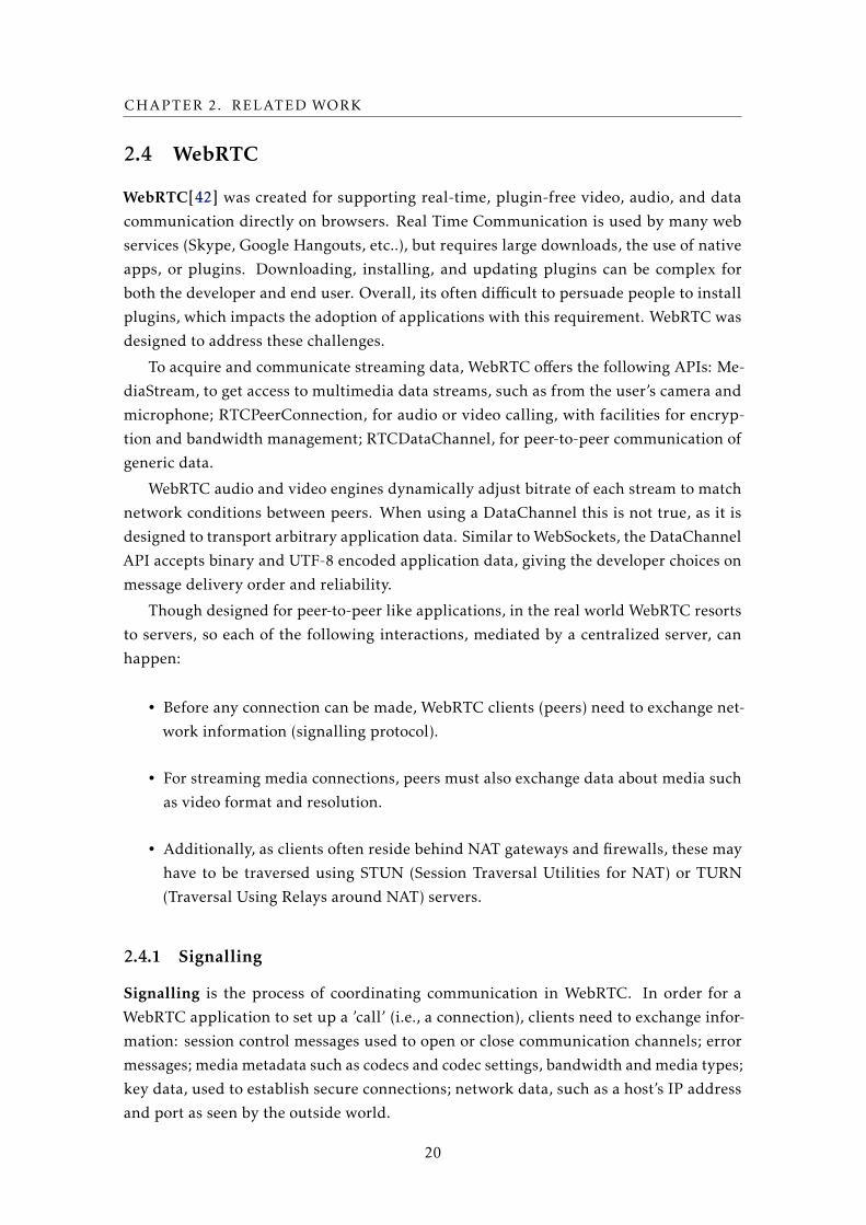
Figure 2.16 depicts the operation of the signalling protocol to establish a WebRTC
connection. A signaling channel can be any medium that allows messages to go back and
forth between clients. This mechanism is not implemented by the WebRTC APIs: it has to
be implemented by the developer. It can be as rudimentary as using e-mail or an instant
messaging application (i.e., an out of band mechanism), it can be done via a centralised
server, and, theoretically, WebRTC’s DataChannels can be used. As depicted in the figure,
when peers reside behind firewalls or NATs they have to make use of STUN or TURN to
establish connections. STUN is used only to obtain the public address for a peer to pass
along via the signalling mechanism. If no connection can be made between two peers
WebRTC can resort to the use of TURN. TURN servers are used to relay the data between
peers.
Figure 2.1: WebRTC Signalling
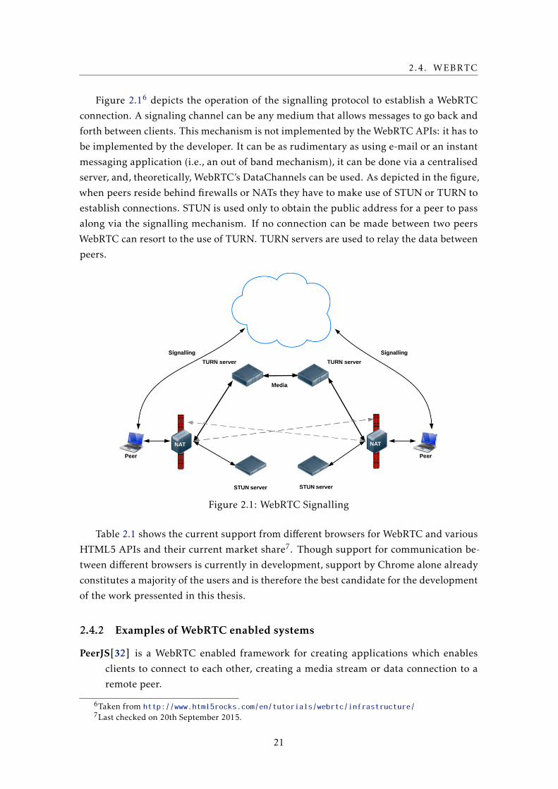
Table 2.1 shows the current support from different browsers for WebRTC and various
HTML5 APIs and their current market share7. Though support for communication be-
tween different browsers is currently in development, support by Chrome alone already
constitutes a majority of the users and is therefore the best candidate for the development
of the work pressented in this thesis.
2.4.2 Examples of WebRTC enabled systems
PeerJS[32] is a WebRTC enabled framework for creating applications which enables
clients to connect to each other, creating a media stream or data connection to a
remote peer.
6Taken from http://www.html5rocks.com/en/tutorials/webrtc/infrastructure/7Last checked on 20th September 2015.
21
CHAPTER 2. RELATED WORK
Table 2.1: Browser Support for HTML APIs
Browser WebRTC LocalStorage WebWorkers Market Share
Chrome Yes Yes Yes 60.1%Firefox Yes Yes Yes 23.4%Opera Yes Yes Yes 1.6%
Microsoft Edge Partial Yes Yes 9.8%Safari No Yes Yes 3.7%
WebRTC Experiment[20] is a collection of frameworks and examples of the use of We-
bRTC, exposing the complete stack to the programmer.
Both these systems allow for the usage of the existing signalling server and the use
of private servers. The implemented examples only illustrate the connection between
two peers and have little to no support for a large number of users (i.e., no peer-to-
peer overlay network creation or support for scalable gossip communication primitives
between nodes).
2.5 Summary
This chapter discussed previous work in the areas related to the development of the work
presented in this thesis.
In the peer-to-peer context the need for an overlay network has been described, ex-
plaining that different application requirements can require different types of overlays.
Overlays can generally be described by degree of centralization and structured versus
unstructured topology.
In the data-storage context we discussed the inherent choice between strong consis-
tency and high availability in distributed systems (that by definition should deal with
network partitions). Different consistency models have been explored and, in the case of
eventual consistency, several techniques for conflict resolution have been described.
In the collaborative-editing context, various commonly used approaches have been
presented and disscussed, describing how concurrency is handled in real-time editing in
each of them.
WebRTC has been presented, describing how peer-to-peer connections can be made
between browsers and what mechanisms exist to facilitate these connections.
22
Chapter
3A Browser-to-browser Framework
In this chapter, we show our proposal of an architecture to enrich the operation of web
based applications with direct browser-to-browser communication. The focus of this
design will be applications that have a high degree of direct user-to-user interaction,
including but not limited to, social networks, chat systems, games, and collaborative
editing systems.
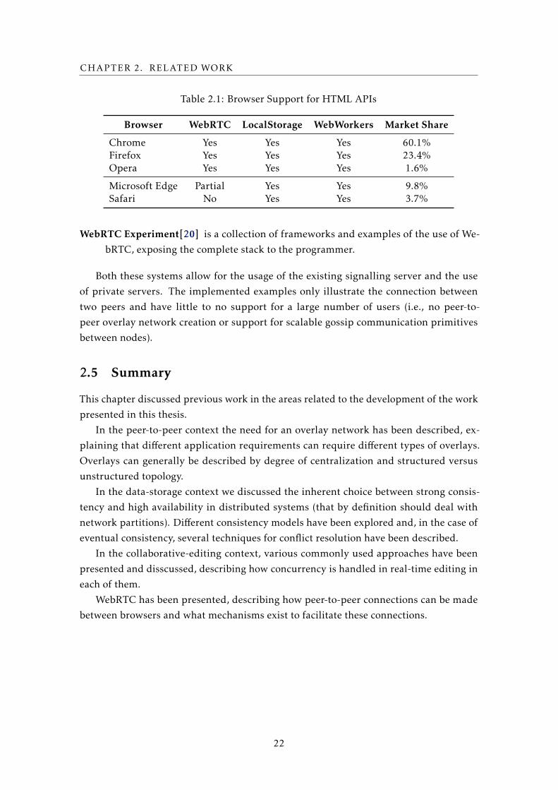
Typically web based applications use a client-server communication model. In this
work we propose to enrich applications as to allow the use of peer-to-peer, or more pre-
cisely in this case: browser-to-browser, communication. Figure 3.1 depicts a parallel
between the commonly used client-server model of web applications (left) and the en-
riched browser-to-browser model we propose in this work (right).
Figure 3.1: Communication model (client-server) | (browser-to-browser)
Note however that in the proposed architecture the centralized component is still a
relevant component which is used for several purposes, namely for data persistence and
to support clients that operate on non WebRTC compliant browsers (i.e., clients whose
browsers do not support direct communication with other browsers). Clients that due
to overly restrictive firewalls policies or due to Network Address Translations (NAT) are
23
CHAPTER 3. A BROWSER-TO-BROWSER FRAMEWORK
unable to estxablish connections to other browsers will also resort to the centralized
component to propagate operations and interact with the system. Additionally, as it will
become clear later in this chapter, the centralized component itself is also used to allow
clients to establish the initial connections between each other when a new client joins the
system.
3.1 Requirements
As previously stated, the work presented in the thesis focuses on Internet applications and
services. The fundamental requirements that a system such as we propose in this thesis
must answer to are: first, improve latency between clients as they are able to directly
communicate between them; second, reduce the dependency on the server as a mediator
for interaction, thus reducing the network load on the centralized component and the
need for constant connection.
Considering these high level goals, we must also provide a good basis for creating web
applications. To simplify the adoption of the hybrid communication model discussed
before, we propose the design of a framework that supports the creation of web applica-
tions without requiring end users to install any kind of software or browser plugins, which
makes the use of the proposed architecture completely transparent and non-intrusive to
clients of web applications built on top of our framework. We must also aim to provide
an extendable API, with a basis similar to existing frameworks.
While we could propose a new API for our framework, we believe that such an ap-
proach would make the adoption (and testing) of our proposal harder. Therefore, we
planned to provide close integration with existing frameworks, mapping existing APIs
to our framework, thus allowing application developers to continue using familiar APIs
while taking advantage of additional support on the clients with data replication and
browser-to-browser communication and synchronization mechanisms (we achieve this
by providing shared data types that are causally consistent and have durable storage).
However, to allow this we had to study the APIs offered by commonly used frameworks,
such that we could steer the design of our framework towards a direction that allows
for supporting such an API, and also to leverage our proposed design to improve those
frameworks.
In this context, we have studied the following frameworks and respective APIs:
• Google Drive Realtime API[17], Dropbox Datastore[10], and ShareJS[15]. All of
these frameworks are used by developers to build applications requiring real-time
concurrent editing of data by multiple users. Each of these can profit from using the
described framework to reduce client-to-client latency and improving scalability of
the centralized component.
• Redis.io[35] is a key-value cache and store. Keys can contain strings, hashes, lists,
sets, among others and is therefore often referred to as a data structure service. Our
24
3.2. INTERACTION MODEL
framework could expand Redis.io to provide clients with the ability to locally apply
operations over these data structures, while reducing client-to-client latency and
server load by sharing them (and respective updates) directly among web clients.
• PeerJS[4] is a peer-to-peer framework supporting the establishment of connections
between a pair of browsers providing a generic data-channel between them. Not
supporting any kind of data-type abstraction, we could easily enrich this framework
with CRDTs and even with group communication primitives that could simplify
the design of applications on top of this framework.
• Priv.io[43] and Sporc[12] are systems that resort to a centralized server for stor-
ing confidential data. Leveraging our framework, it would be possible to leverage
peer-to-peer communication patterns to improve performance and lower trust in
centralized components.
We opted to initially create a browser-to-browser communication layer, offering the
creation of overlay networks with a messaging API, similar to PeerJS and other messaging
systems. On top of the connection and messaging systems, we have decided to add an
interface similar to the one offered by the Google Drive Realtime API, using CRDTs
internally, to simplify both object replication and synchronization.
3.2 Interaction model
As referred previously, in the classic client-server model all interactions between clients
are mediated trough a centralized component. This component is responsible for serving
all data objects that the application requires, while also processing all operations that
update and modify application state executed by any client.
In our proposal we extend this traditional model as we also offer to the clients the
capability to serve replicas of objects directly between them (especially between those
that are close, for example, on the same local network), while being able to operate over
those objects locally and propagate updates in a decentralized fashion. This allows us
to substantially reduce the dependency on the centralized component, which brings sev-
eral advantages such as the possibility to lower server load and improve latency between
clients. In contrast to the client-server communication model this also allows for in-
teraction between clients even when the centralized component becomes temporarily
unavailable.
These additional mechanisms imply that the interaction model of client applications
with the centralized component that supports a particular web application or service will
change substantially from the use commonly found. In more detail, the interaction model
we consider in this work is as follows:
25
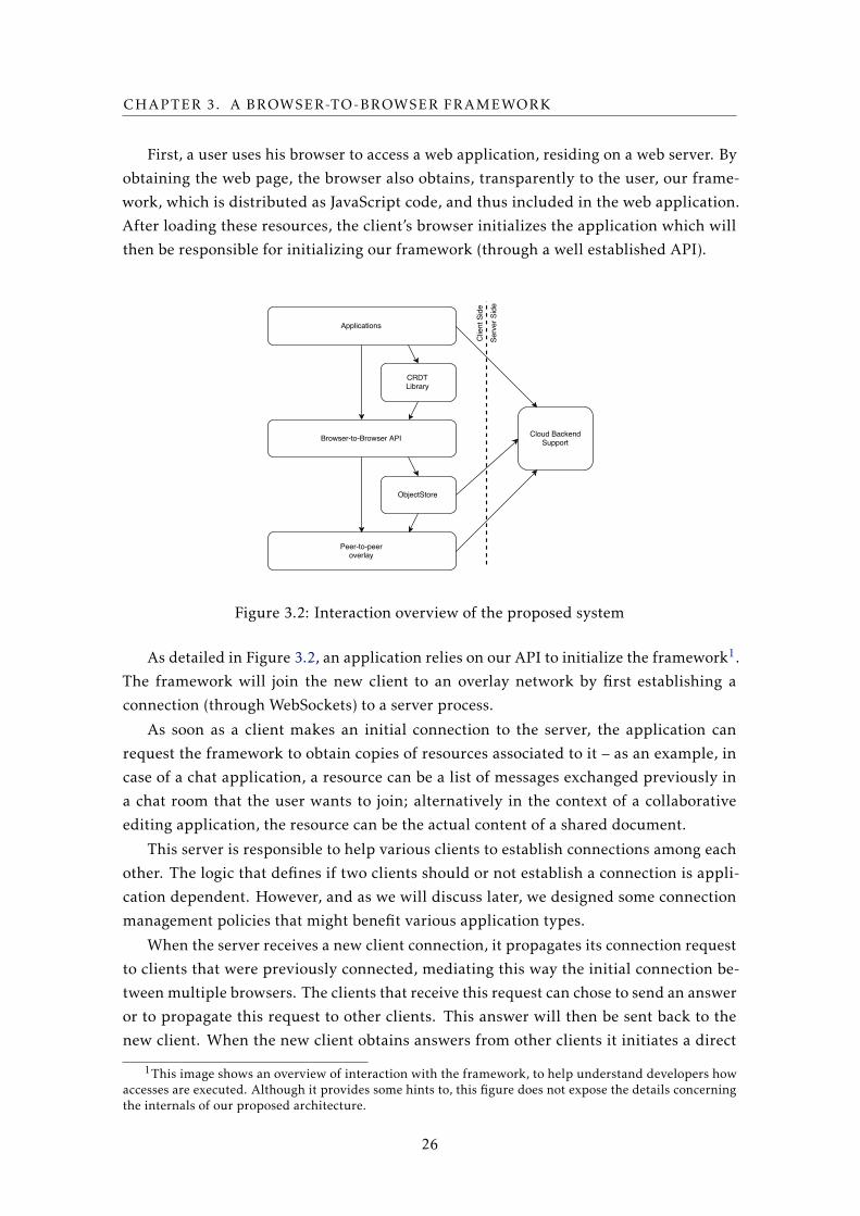
CHAPTER 3. A BROWSER-TO-BROWSER FRAMEWORK
First, a user uses his browser to access a web application, residing on a web server. By
obtaining the web page, the browser also obtains, transparently to the user, our frame-
work, which is distributed as JavaScript code, and thus included in the web application.
After loading these resources, the client’s browser initializes the application which will
then be responsible for initializing our framework (through a well established API).
Figure 3.2: Interaction overview of the proposed system
As detailed in Figure 3.2, an application relies on our API to initialize the framework1.
The framework will join the new client to an overlay network by first establishing a
connection (through WebSockets) to a server process.
As soon as a client makes an initial connection to the server, the application can
request the framework to obtain copies of resources associated to it – as an example, in
case of a chat application, a resource can be a list of messages exchanged previously in
a chat room that the user wants to join; alternatively in the context of a collaborative
editing application, the resource can be the actual content of a shared document.
This server is responsible to help various clients to establish connections among each
other. The logic that defines if two clients should or not establish a connection is appli-
cation dependent. However, and as we will discuss later, we designed some connection
management policies that might benefit various application types.
When the server receives a new client connection, it propagates its connection request
to clients that were previously connected, mediating this way the initial connection be-
tween multiple browsers. The clients that receive this request can chose to send an answer
or to propagate this request to other clients. This answer will then be sent back to the
new client. When the new client obtains answers from other clients it initiates a direct
1This image shows an overview of interaction with the framework, to help understand developers howaccesses are executed. Although it provides some hints to, this figure does not expose the details concerningthe internals of our proposed architecture.
26
3.2. INTERACTION MODEL
browser-to-browser connection. This new client is thus responsible, using the server as
mediator, to connect, in a peer-to-peer fashion, to other clients.
To this end we resort to the mechanisms offered by Web Real Time Communication
(WebRTC[42]), that, on its own, can resort to STUN and TURN servers2 for support to
surpass firewalls and NATs that restrain browser-to-browser connections.
When connections are established to other clients the communication that is done
initially via the server is, transparently to the user, re-directed to use the browser-to-
browser communication model.
The resources associated to the application that a client has requested can thus now be
requested to other clients. Objects are replicated between clients using the appropriated
CRDTs for the kind of data the application needs. CRDTs allow to minimize coordenation
between clients when executing operations on their local replicas. Also, these data types
allow for replicated objects to converge to a common single shared state. They also allow
clients to aggregate various operations of various neighbours to a single message to be
propagated to the central component, creating the opportunity to minimize load on this
component. This way we are able to reduce client-to-client latency especially on nearby
clients, and reduce server load when groups of clients collaborate among each other
to aggregate updates. It also becomes possible to avoid the central point of failure. In
current architectures, the server is the only communication medium and when it becomes
even temporarily unavailable all user interaction is halted. When we allow for browser-
to-browser communication all clients can interact between each other, interaction can
continue even with temporary server failures.
Considering this interaction model, the framework is composed of the following main
logical components:
• A logical peer-to-peer connectivity layer between end users’ browsers, supporting
the choice between various overlay network configurations. As shown in Section
2.1.1, the applicational needs weight heavily in the choice of the overlay network.
Therefore the chosen overlay must be the one that best fits the requirements of pos-
sible applications. WebRTC is used as a generic browser-to-browser data transport
layer and WebSockets3 are used for communication with the centralized compo-
nent of the web application or service. This allows for a generic messaging system
between browsers to operate on top of the overlay network.
• Object replication mechanisms which provide the ability to implement CRDTs en-
abling real-time concurrent manipulation and synchronization of application data
objects in a fully decentralized and distributed fashion. The previously described
2While these can be privately deployed, we resort to those provided publicly by Google.3WebSockets are implemented by all major browsers and allow for a TCP connections to be established
between a browser and a web server, enabling asynchronous client-to-server and even server-to-client com-munication.
27
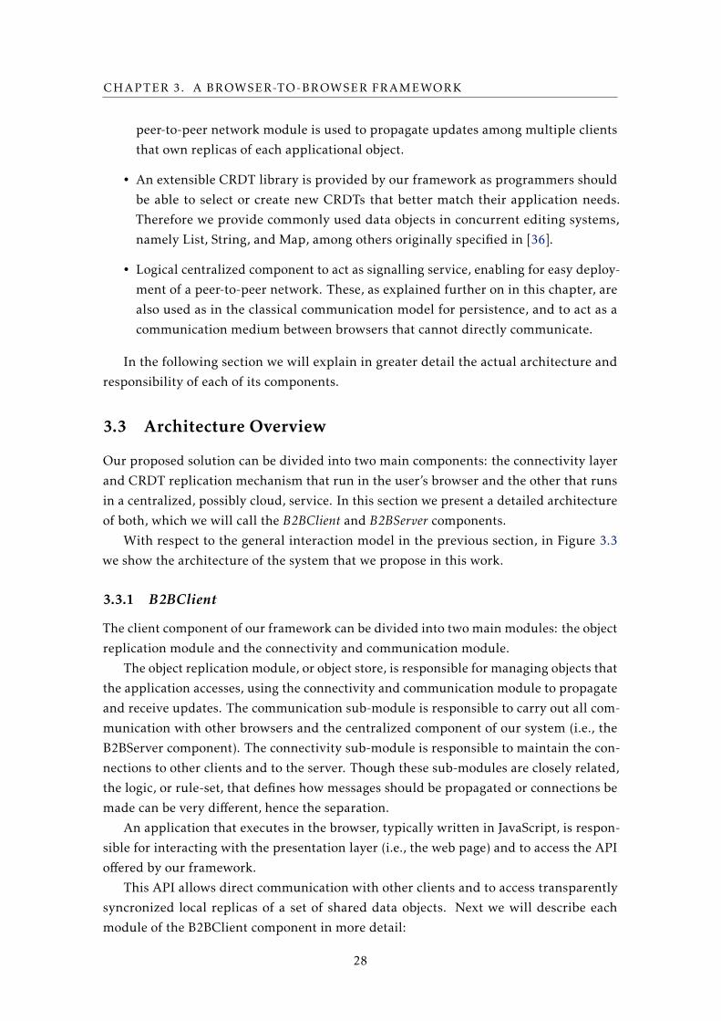
CHAPTER 3. A BROWSER-TO-BROWSER FRAMEWORK
peer-to-peer network module is used to propagate updates among multiple clients
that own replicas of each applicational object.
• An extensible CRDT library is provided by our framework as programmers should
be able to select or create new CRDTs that better match their application needs.
Therefore we provide commonly used data objects in concurrent editing systems,
namely List, String, and Map, among others originally specified in [36].
• Logical centralized component to act as signalling service, enabling for easy deploy-
ment of a peer-to-peer network. These, as explained further on in this chapter, are
also used as in the classical communication model for persistence, and to act as a
communication medium between browsers that cannot directly communicate.
In the following section we will explain in greater detail the actual architecture and
responsibility of each of its components.
3.3 Architecture Overview
Our proposed solution can be divided into two main components: the connectivity layer
and CRDT replication mechanism that run in the user’s browser and the other that runs
in a centralized, possibly cloud, service. In this section we present a detailed architecture
of both, which we will call the B2BClient and B2BServer components.
With respect to the general interaction model in the previous section, in Figure 3.3
we show the architecture of the system that we propose in this work.
3.3.1 B2BClient
The client component of our framework can be divided into two main modules: the object
replication module and the connectivity and communication module.
The object replication module, or object store, is responsible for managing objects that
the application accesses, using the connectivity and communication module to propagate
and receive updates. The communication sub-module is responsible to carry out all com-
munication with other browsers and the centralized component of our system (i.e., the
B2BServer component). The connectivity sub-module is responsible to maintain the con-
nections to other clients and to the server. Though these sub-modules are closely related,
the logic, or rule-set, that defines how messages should be propagated or connections be
made can be very different, hence the separation.
An application that executes in the browser, typically written in JavaScript, is respon-
sible for interacting with the presentation layer (i.e., the web page) and to access the API
offered by our framework.
This API allows direct communication with other clients and to access transparently
syncronized local replicas of a set of shared data objects. Next we will describe each
module of the B2BClient component in more detail:
28
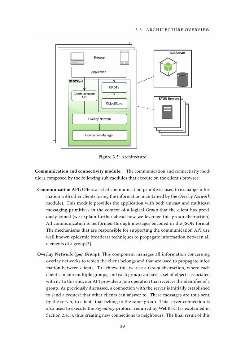
3.3. ARCHITECTURE OVERVIEW
Figure 3.3: Architecture
Communication and connectivity module: The communication and connectivity mod-
ule is composed by the following sub-modules that execute on the client’s browser:
Communication API: Offers a set of communication primitives used to exchange infor-
mation with other clients (using the information maintained by the Overlay Networkmodule). This module provides the application with both unicast and multicast
messaging primitives in the context of a logical Group that the client has previ-
ously joined (we explain further ahead how we leverage this group abstraction).
All communication is performed through messages encoded in the JSON format.
The mechanisms that are responsible for supporting the communication API use
well known epidemic broadcast techniques to propagate information between all
elements of a group[3].
Overlay Network (per Group): This component manages all information concerning
overlay networks to which the client belongs and that are used to propagate infor-
mation between clients. To achieve this we use a Group abstraction, where each
client can join multiple groups, and each group can have a set of objects associated
with it. To this end, our API provides a Join operation that receives the identifier of a
group. As previously discussed, a connection with the server is initially established
to send a request that other clients can answer to. These messages are thus sent,
by the server, to clients that belong to the same group. This server connection is
also used to execute the Signalling protocol required by WebRTC (as explained in
Section 2.4.1), thus creating new connections to neighbours. The final result of this
29
CHAPTER 3. A BROWSER-TO-BROWSER FRAMEWORK
process is that the clients, for each group, become connected to an overlay network
whose topology is similar to a random graph with bi-directional connections, with
properties that closely map on the overlay networks maintained by algorithms used
in peer-to-peer systems like Cyclon[40], Scamp[14], or HyParView[25]. This com-
ponent also keeps information on the logical neighbours (i.e., other clients) of the
client in each logical overlay network (i.e., one per group) to which the client has
joined, while it also implements algorithms for efficient propagation of messages
within a group.
Though the server is needed to establish initial connections to other clients, the
connections to other clients themselves can be used to find new neighbours and
even execute the Signalling protocol. This way, within a group, more connections
can be created. As neighbours can possibly be members of various groups the client
has not yet joined, the client’s neighbours themselves can be used directly to join
new groups.
To avoid overloading the central component with excessive updates relative to oper-
ations by clients over data objects, only a sub-set of the clients maintain a connection
to the server. In order to decide which client is responsible for this task we resort
to a Bullying[8] algorithm that is used to perform (multiple) leader elections in the
context of each logical group4. In this algorithm each client starts in an active state
and, periodically, emits to each neighbour a message containing its identifier. Each
time a client receives an identifier that is lower than its own, the client changes its
state to inert, stops broadcasting the periodic message and disconnects from the
centralized component. An inert node that doesn’t receive these messages for a long
period of time changes its state back to active and re-connects to the central compo-
nent (restarting to emit the periodic messages). Only nodes in active state are thus
responsible for interacting with the centralized component, which includes sending
messages and aggregating and propagating operations performed over replicated
objects for persistence at the central component.
Connection Manager: This component is responsible for the creation and management
of connections between clients and also to the centralized component (when re-
quired). The use of this component enables us to avoid redundant connections
between clients that join multiple groups and with the centralized component.
The ConnectionManager resorts to the WebRTC API to create connections between
clients and to WebSockets to create connections from clients to the server. WebRTC
has native support in the most used web browsers, namely Chrome and Firefox,
being possible to resort to instalable plugins to support WebRTC in other browsers.
One of the main reasons that motivates the use of WebRTC is the native support in
these browsers, as this allows for the use of our framework without any effort (e.g,
4We say multiple leader election because, as the network resembles a random graph and not all clientsare connected to all clients, within a single group multiple leaders can be elected.
30
3.3. ARCHITECTURE OVERVIEW
installing software or configuring firewalls and NATs) by the end user. WebRTC
always uses secure connections, where all data is encrypted which minimizes the
concerns concerning privacy breaches due to eavesdroppers5.
The existence of Firewalls and NATs have always been a challenge in the deployment
and adoption of peer-to-peer systems in the past, as they difficult (or impede) the
establishment of connections and direct communication between clients that are
behind one of these components. To bypass this practical challenge, WebRTC resorts
to services specifically designed to facilitate establishment of connections in these
scenarios. There are two kinds of services that can be used. STUN which allows
nodes to determine their public IP addresses (in the case of NAT) and install state in
firewalls or NATs to allow for direct communication. A second alternative is using
TURN services, where external TURN servers are used to redirect traffic between
each pair of communicating clients. In the context of our work the use of TURN has
been disabled by default (though enabling it is possible). The usage scenarios that
we focus on it is more efficient for clients to communicate indirectly through the
centralized component of the system than to have all their direct communication
redirected by a server the application has no control over. In these cases, just as
when a browser doesn’t support WebRTC, the framework resorts to the classic client-
server interaction model of Web applications, where all user actions are mediated
by a centralized component.
In order to establish a direct browser-to-browser connection, WebRTC uses a Sig-nalling protocol (as discussed in Section 2.4.1) that requires both clients to exchange
information between them. Any mechanism that allows for an exchange of text can
be used to materialize this signalling protocol. In our framework, we opt to use
the centralized component, by leveraging the existing WebSocket connections, to
carry out the necessary information exchange to establish these connections. This
decision is also motivated by the fact that most Web services require an authenti-
cation process by the user, which necessarily requires sending information to the
centralized component when the client starts using the service.
Object store: This module allows, to an application that executes in a browser, to share
objects with other client applications that execute remotely in other browsers – typically,
instances of the same application. These shared objects contain data manipulated by
the application allowing users to co-operate and exchange information by concurrently
modifying these same objects. The object store, present in each browser, is composed of
the following:
Object replication : This sub-module is responsible for using the group communication
primitives to obtain the initial state of objects and to keep these objects updated.
5As the reader might expect, the use of this framework rises preoccupations concerning base privacy andsecurity. We intend to address these issues in future work.
31
CHAPTER 3. A BROWSER-TO-BROWSER FRAMEWORK
To maintain objects up to date, the system leverages the Overlay Network’s commu-
nication primitives to propagate updates made by individual clients among them.
All updates are shared with neighbours and also with the centralized component
for durability. The system allows for updates to be queued before propagation, in
order to allow for multiple updates to be aggregated and sent in a single message.
This module allows to obtain a string representation of the object’s state and to
create an object from such a string representation. This allows for the usage of any
type of client-side persistence to keep local persistent copies of CRDTs. This enables
the possibility for clients that are initializing to load a previously known state from
the client device, this immediately enables working with the object while updates
to it will eventually, as connections are established and used, be added to the local
copy.
CRDT Library : This sub-module provides a set of data types based on CRDT principles
coded in JavaScript. This library is used by the application to access objects relevant
to the application. We provide a set of commonly used data types (List, String, Map,
and Set) which can be used as building blocks for creating applications. This library
can be extended by the programmer by defining new types of CRDTs that are better
adjusted to the application requirements.
3.3.2 B2BServer
To support the services offered at the client side and to allow browser-to-browser commu-
nication, our system also includes the following modules that are executed in a centralized
component, potentially in a cloud computing enviroment:
B2BServer : The centralized component is materialized trough a server process written
in NodeJS. This server receives connections from the client’s ConnectionManager
(through WebSockets) and acts as an entry point of the clients to our framework.
This component acts as an intermediary during the establishment of direct connec-
tions between clients. Also, this component is responsible for mediating the access
between clients and the persistence layer of the system, including the access to ob-
jects that are not yet available in the clients, and to receive updates on those objects
to guarantee the correct storage in the (centralized) persistence layer.
This component is also responsible to serve the clients that are unable to establish
browser-to-browser connections with other clients.
STUN Servers : These servers are out of the scope of this work and thus out of the
control of our solution. Though possible to be deployed by the application operator, in
the context of this work we use those publicly available from Google. STUN servers are
used to allow clients that are behind firewalls and NATs to establish browser-to-browser
32

3.3. ARCHITECTURE OVERVIEW
connections. It is also possible to use TURN servers although, as previously discussed,
the usage of these is disabled by default (but can be explicitly enabled).
33

Chapter
4Browser-to-browser interaction framework
This chapter gives an overview of the API provided by our framework. We detail the avail-
able API calls and, subsequently, the designed algorithms that support the functionalities
provided by the API.
We start by giving a general overview of how the interface can be used. As depicted
in Figure 4.1 we show that in the general use case an application has the following
interactions with our interface:
To initialize our framework making it available to the application a ConnectionMan-ager object has to be created (a). This object receives as a parameter the server address that
it connects to (when needed). This object allows the application to Join and Leave groups.
When a Group is joined we enable sending and receiving multicast and point-to-point
messages (b) in the context of this Group (Section 4.1). A Group offers an object-store to
create and interact with objects. Though objects and the object-store can be interacted
with directly, normally CRDTs (c) will be used as an encapsulation and thus applications
interact with them instead (Section 4.2).
Furthermore, in Section 4.3 we discuss relevant parameters and their effects on the
framework and system behaviour, in Section 4.4 we explain how to perform server setup,
and section 4.5 provides a description of our prototype implementation discussing the
most relevant implementation decisions.
4.1 Browser-to-Browser Communication
As explained previously, in our approach communication is performed within the context
of groups (detailed in section 4.3). When a Group object is obtained, the application is
supplied with an interface to interact with the elements of that group (i.e., other instances
of the application that also joined the group). The available calls are presented in Listing
35
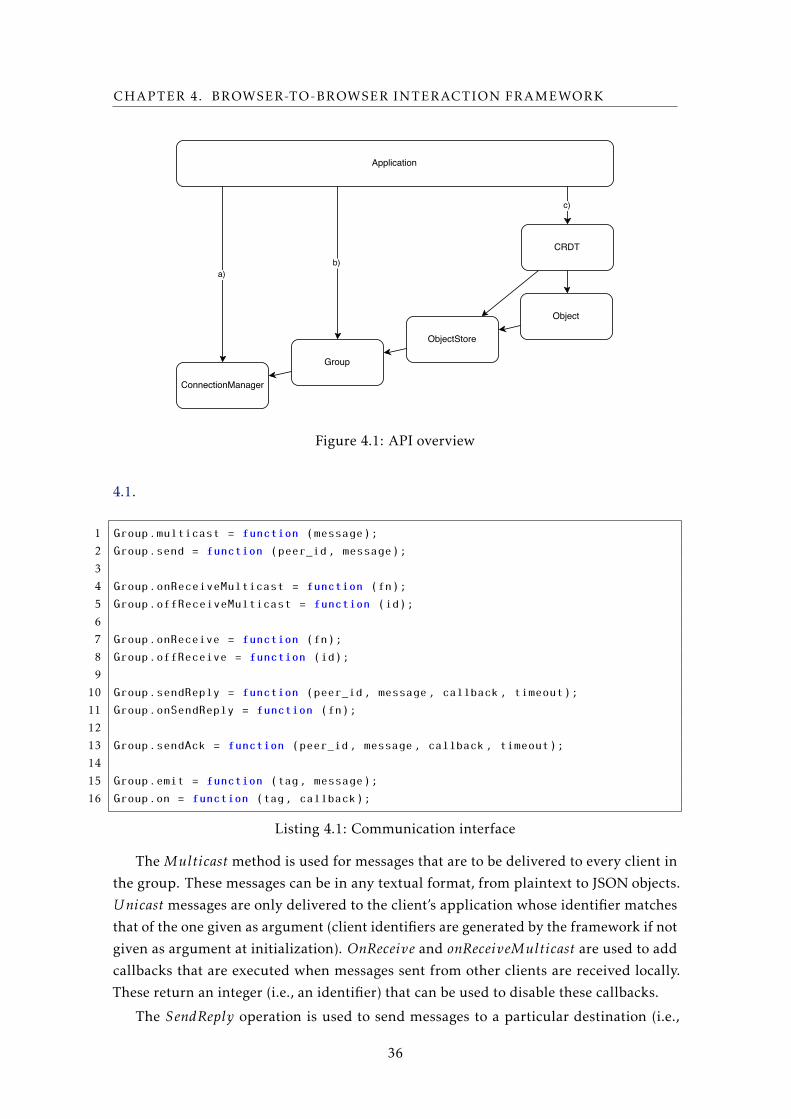
CHAPTER 4. BROWSER-TO-BROWSER INTERACTION FRAMEWORK
Figure 4.1: API overview
4.1.
1 Group.multicast = function (message);
2 Group.send = function (peer_id, message);
3
4 Group.onReceiveMulticast = function (fn);
5 Group.offReceiveMulticast = function (id);
6
7 Group.onReceive = function (fn);
8 Group.offReceive = function (id);
9
10 Group.sendReply = function (peer_id, message, callback, timeout);
11 Group.onSendReply = function (fn);
12
13 Group.sendAck = function (peer_id, message, callback, timeout);
14
15 Group.emit = function (tag, message);
16 Group.on = function (tag, callback);
Listing 4.1: Communication interface
The Multicast method is used for messages that are to be delivered to every client in
the group. These messages can be in any textual format, from plaintext to JSON objects.
Unicast messages are only delivered to the client’s application whose identifier matches
that of the one given as argument (client identifiers are generated by the framework if not
given as argument at initialization). OnReceive and onReceiveMulticast are used to add
callbacks that are executed when messages sent from other clients are received locally.
These return an integer (i.e., an identifier) that can be used to disable these callbacks.
The SendReply operation is used to send messages to a particular destination (i.e.,
36
4.1. BROWSER-TO-BROWSER COMMUNICATION
client) and accepts a callback for processing the corresponding answer. The callback
is executed with the answer or null if the timeout (configured with the timeout value)
expires without the reception of the expected answer from the other endpoint. To be
able to send replies at the receiver side, the onSendReply method has to be previously
executed (typically at initialization time) to explicitly configure a handler which accepts
the message (type) and returns the intended answer. The SendAck operation is similar to
SendReply as it waits for an acknowledge from the client where the message is delivered
at, but no handler has to be specified (and thus only a boolean value is returned meaning
the message has been received at the destination or reporting that no delivery has been
guaranteed within the specified timeout).
To provide a similar interaction to that of publish/subscribe systems, we provide the
emit function to emit messages that are labelled with a particular (or multiple) tag, while
the on method can be used to add callbacks for handling messages disseminated through
the emit operation, based on their tags.
With respect to this API it is clear that there are no guarantees that all clients will
always receive every message (as in, at least once delivery guarantees), and that the order
of delivery of messages will be the same at all clients. We use optimistic propagation
mechanisms (as we detail in Section 4.3) and ensure that each message explicitly sent is
delivered at most once (at most once delivery).
Algorithm 1 shows the algorithms used by our framework to support these calls.
Upon denotes a call that was performed by the programmer explicitly and OnReceive
denotes the reception of a message from the network. All propagation of messages1 is
done through the use of flooding techniques over the available overlay (i.e., logical) net-
work, with respect to the algorithms that can be selected when initializing the framework.
The P ropagate call is thus detailed in Section 4.3. For the sake of simplicity, message
identifiers and duplication detection are omitted from the algorithms.
4.1.1 Example
To show how the programmer interface can be used, a small example is provided in
Listing 4.2. The details regarding the user interface have been omitted (these details
include aspects as the HTML code and the HTML manipulating JavaScript code). The
example shows the relevant code to create a simple chat application where users can join
rooms.
As previously stated, we first have to create the ConnectionManager object (Line 1).
This object can then be used to Join groups. Each room can be joined (or created) by
providing a name, which serves as the group identifier (Line 5). These groups can be
stored for future use and to add event handlers, where in this case we listen for multicast
messages (Line 7). When we want to send messages ourselves, the right group’s method
for disseminating messages has to be used, in this case, multicast (Line 15).
1Except those that follow a point-to-point communication pattern.
37
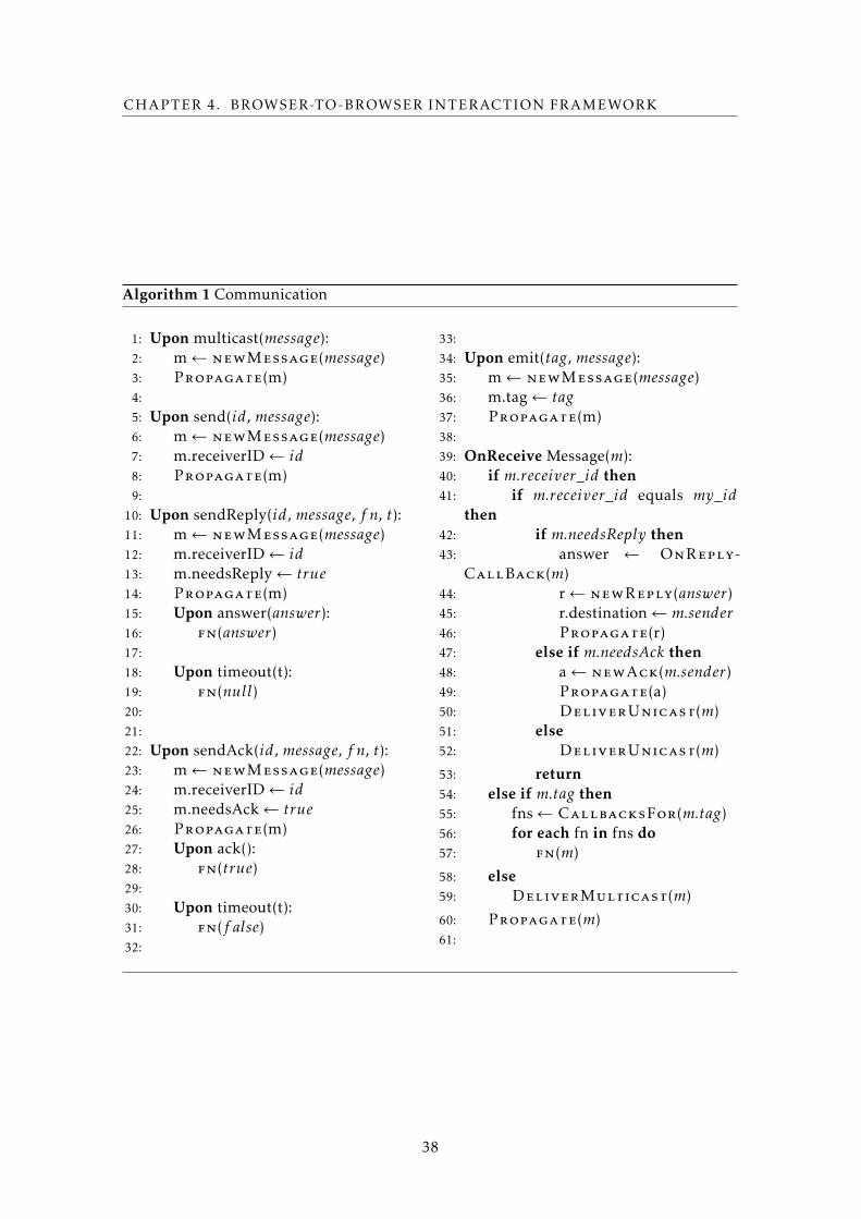
CHAPTER 4. BROWSER-TO-BROWSER INTERACTION FRAMEWORK
Algorithm 1 Communication
1: Upon multicast(message):2: m← newMessage(message)3: Propagate(m)4:
5: Upon send(id, message):6: m← newMessage(message)7: m.receiverID← id8: Propagate(m)9:
10: Upon sendReply(id, message, f n, t):11: m← newMessage(message)12: m.receiverID← id13: m.needsReply← true14: Propagate(m)15: Upon answer(answer):16: fn(answer)17:
18: Upon timeout(t):19: fn(null)20:
21:
22: Upon sendAck(id, message, f n, t):23: m← newMessage(message)24: m.receiverID← id25: m.needsAck← true26: Propagate(m)27: Upon ack():28: fn(true)29:
30: Upon timeout(t):31: fn(f alse)32:
33:
34: Upon emit(tag, message):35: m← newMessage(message)36: m.tag← tag37: Propagate(m)38:
39: OnReceive Message(m):40: if m.receiver_id then41: if m.receiver_id equals my_id
then42: if m.needsReply then43: answer ← OnReply-
CallBack(m)44: r← newReply(answer)45: r.destination← m.sender46: Propagate(r)47: else if m.needsAck then48: a← newAck(m.sender)49: Propagate(a)50: DeliverUnicast(m)51: else52: DeliverUnicast(m)
53: return54: else if m.tag then55: fns← CallbacksFor(m.tag)56: for each fn in fns do57: fn(m)
58: else59: DeliverMulticast(m)
60: Propagate(m)61:
38
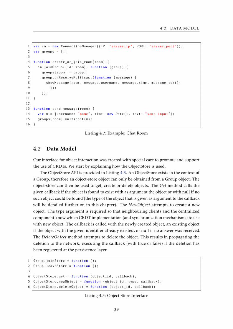
4.2. DATA MODEL
1 var cm = new ConnectionManager({IP: "server_ip", PORT: "server_port"});
2 var groups = [];
3
4 function create_or_join_room(room) {
5 cm.joinGroup({id: room}, function (group) {
6 groups[room] = group;
7 group.onReceiveMulticast(function (message) {
8 showMessage(room, message.username, message.time, message.text);
9 });
10 });
11 }
12
13 function send_message(room) {
14 var m = {username: "name", time: new Date(), text: "some input"};
15 groups[room].multicast(m);
16 }
Listing 4.2: Example: Chat Room
4.2 Data Model
Our interface for object interaction was created with special care to promote and support
the use of CRDTs. We start by explaining how the ObjectStore is used.
The ObjectStore API is provided in Listing 4.3. An ObjectStore exists in the context of
a Group, therefore an object-store object can only be obtained from a Group object. The
object-store can then be used to get, create or delete objects. The Get method calls the
given callback if the object is found to exist with as argument the object or with null if no
such object could be found (the type of the object that is given as argument to the callback
will be detailed further on in this chapter). The NewObject attempts to create a new
object. The type argument is required so that neighbouring clients and the centralized
component know which CRDT implementation (and synchronization mechanisms) to use
with new object. The callback is called with the newly created object, an existing object
if the object with the given identifier already existed, or null if no answer was received.
The DeleteObject method attempts to delete the object. This results in propagating the
deletion to the network, executing the callback (with true or false) if the deletion has
been registered at the persistence layer.
1 Group.joinStore = function ();
2 Group.leaveStore = function ();
3
4 ObjectStore.get = function (object_id, callback);
5 ObjectStore.newObject = function (object_id, type, callback);
6 ObjectStore.deleteObject = function (object_id, callback);
Listing 4.3: Object Store Interface
39
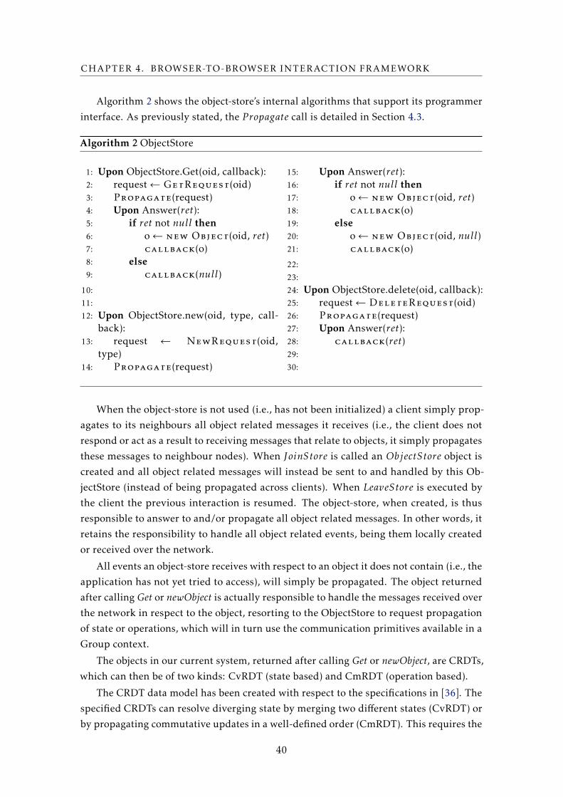
CHAPTER 4. BROWSER-TO-BROWSER INTERACTION FRAMEWORK
Algorithm 2 shows the object-store’s internal algorithms that support its programmer
interface. As previously stated, the P ropagate call is detailed in Section 4.3.
Algorithm 2 ObjectStore
1: Upon ObjectStore.Get(oid, callback):2: request← GetRequest(oid)3: Propagate(request)4: Upon Answer(ret):5: if ret not null then6: o← new Object(oid, ret)7: callback(o)8: else9: callback(null)
10:
11:
12: Upon ObjectStore.new(oid, type, call-back):
13: request ← NewRequest(oid,type)
14: Propagate(request)
15: Upon Answer(ret):16: if ret not null then17: o← new Object(oid, ret)18: callback(o)19: else20: o← new Object(oid, null)21: callback(o)
22:
23:
24: Upon ObjectStore.delete(oid, callback):25: request← DeleteRequest(oid)26: Propagate(request)27: Upon Answer(ret):28: callback(ret)29:
30:
When the object-store is not used (i.e., has not been initialized) a client simply prop-
agates to its neighbours all object related messages it receives (i.e., the client does not
respond or act as a result to receiving messages that relate to objects, it simply propagates
these messages to neighbour nodes). When JoinStore is called an ObjectStore object is
created and all object related messages will instead be sent to and handled by this Ob-
jectStore (instead of being propagated across clients). When LeaveStore is executed by
the client the previous interaction is resumed. The object-store, when created, is thus
responsible to answer to and/or propagate all object related messages. In other words, it
retains the responsibility to handle all object related events, being them locally created
or received over the network.
All events an object-store receives with respect to an object it does not contain (i.e., the
application has not yet tried to access), will simply be propagated. The object returned
after calling Get or newObject is actually responsible to handle the messages received over
the network in respect to the object, resorting to the ObjectStore to request propagation
of state or operations, which will in turn use the communication primitives available in a
Group context.
The objects in our current system, returned after calling Get or newObject, are CRDTs,
which can then be of two kinds: CvRDT (state based) and CmRDT (operation based).
The CRDT data model has been created with respect to the specifications in [36]. The
specified CRDTs can resolve diverging state by merging two different states (CvRDT) or
by propagating commutative updates in a well-defined order (CmRDT). This requires the
40
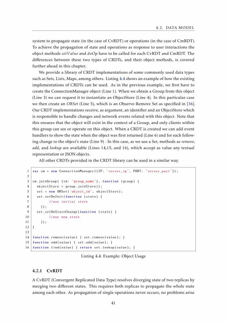
4.2. DATA MODEL
system to propagate state (in the case of CvRDT) or operations (in the case of CmRDT).
To achieve the propagation of state and operations as response to user interactions the
object methods setV alue and doOp have to be called for each CvRDT and CmRDT. The
differences between these two types of CRDTs, and their object methods, is covered
further ahead in this chapter.
We provide a library of CRDT implementations of some commonly used data types
such as Sets, Lists, Maps, among others. Listing 4.4 shows an example of how the existing
implementations of CRDTs can be used. As in the previous example, we first have to
create the ConnectionManager object (Line 1). When we obtain a Group from this object
(Line 3) we can request it to instantiate an ObjectStore (Line 4). In this particular case
we then create an ORSet (Line 5), which is an Observe-Remove Set as specified in [36].
Our CRDT implementations receive, as argument, an identifier and an ObjectStore which
is responsible to handle changes and network events related with this object. Note that
this ensures that the object will exist in the context of a Group, and only clients within
this group can see or operate on this object. When a CRDT is created we can add event
handlers to show the state when the object was first returned (Line 6) and for each follow-
ing change to the object’s state (Line 9) . In this case, as we use a Set, methods as remove,
add, and lookup are available (Lines 14,15, and 16), which accept as value any textual
representation or JSON objects.
All other CRDTs provided in the CRDT library can be used in a similar way.
1 var cm = new ConnectionManager({IP: ’server_ip’, PORT: ’server_port’});
2
3 cm.joinGroup( {id: ’group_name’}, function (group) {
4 objectStore = group.joinStore();
5 set = new ORSet(’object_id’, objectStore);
6 set.setOnInit(function (state) {
7 //use initial state
8 });
9 set.setOnStateChange(function (state) {
10 //use new state
11 });
12 }
13
14 function remove(value) { set.remove(value); }
15 function add(value) { set.add(value); }
16 function find(value) { return set.lookup(value); }
Listing 4.4: Example: Object Usage
4.2.1 CvRDT
A CvRDT (Convergent Replicated Data Type) resolves diverging state of two replicas by
merging two different states. This requires both replicas to propagate the whole state
among each other. As propagation of single operations never occurs, no problems arise
41
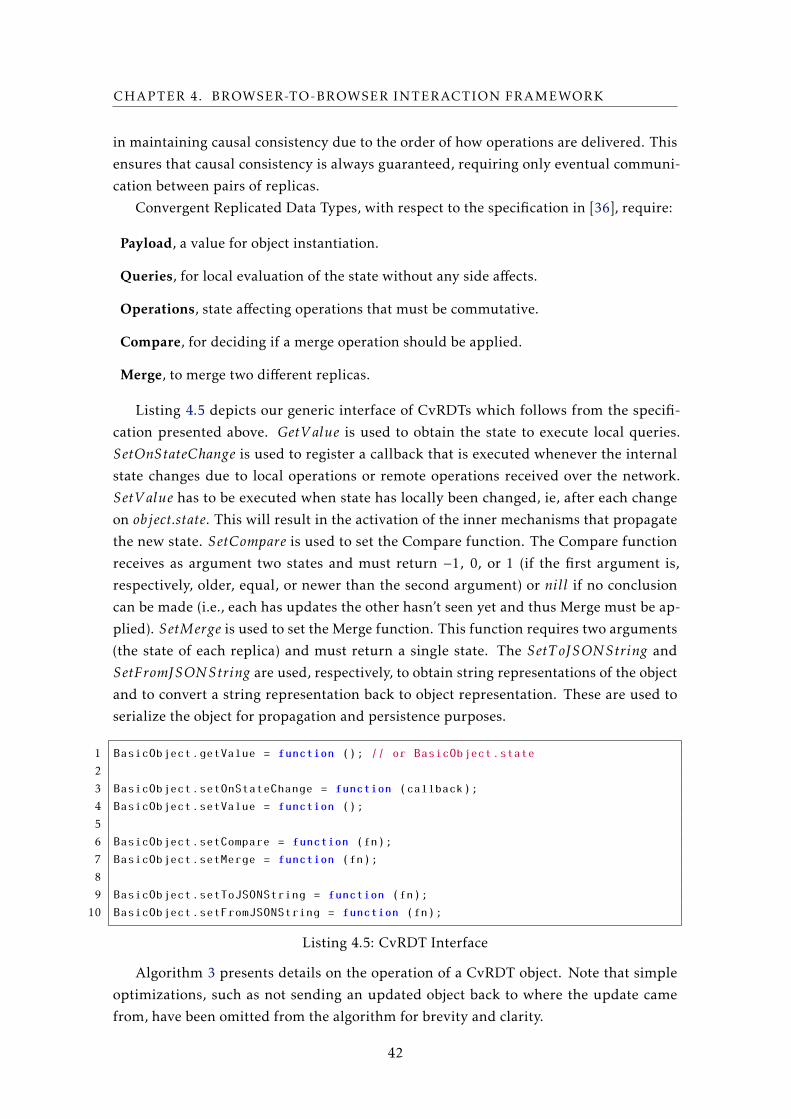
CHAPTER 4. BROWSER-TO-BROWSER INTERACTION FRAMEWORK
in maintaining causal consistency due to the order of how operations are delivered. This
ensures that causal consistency is always guaranteed, requiring only eventual communi-
cation between pairs of replicas.
Convergent Replicated Data Types, with respect to the specification in [36], require:
Payload, a value for object instantiation.
Queries, for local evaluation of the state without any side affects.
Operations, state affecting operations that must be commutative.
Compare, for deciding if a merge operation should be applied.
Merge, to merge two different replicas.
Listing 4.5 depicts our generic interface of CvRDTs which follows from the specifi-
cation presented above. GetV alue is used to obtain the state to execute local queries.
SetOnStateChange is used to register a callback that is executed whenever the internal
state changes due to local operations or remote operations received over the network.
SetV alue has to be executed when state has locally been changed, ie, after each change
on object.state. This will result in the activation of the inner mechanisms that propagate
the new state. SetCompare is used to set the Compare function. The Compare function
receives as argument two states and must return −1, 0, or 1 (if the first argument is,
respectively, older, equal, or newer than the second argument) or nill if no conclusion
can be made (i.e., each has updates the other hasn’t seen yet and thus Merge must be ap-
plied). SetMerge is used to set the Merge function. This function requires two arguments
(the state of each replica) and must return a single state. The SetT oJSONString and
SetFromJSONString are used, respectively, to obtain string representations of the object
and to convert a string representation back to object representation. These are used to
serialize the object for propagation and persistence purposes.
1 BasicObject.getValue = function (); // or BasicObject.state
2
3 BasicObject.setOnStateChange = function (callback);
4 BasicObject.setValue = function ();
5
6 BasicObject.setCompare = function (fn);
7 BasicObject.setMerge = function (fn);
8
9 BasicObject.setToJSONString = function (fn);
10 BasicObject.setFromJSONString = function (fn);
Listing 4.5: CvRDT Interface
Algorithm 3 presents details on the operation of a CvRDT object. Note that simple
optimizations, such as not sending an updated object back to where the update came
from, have been omitted from the algorithm for brevity and clarity.
42
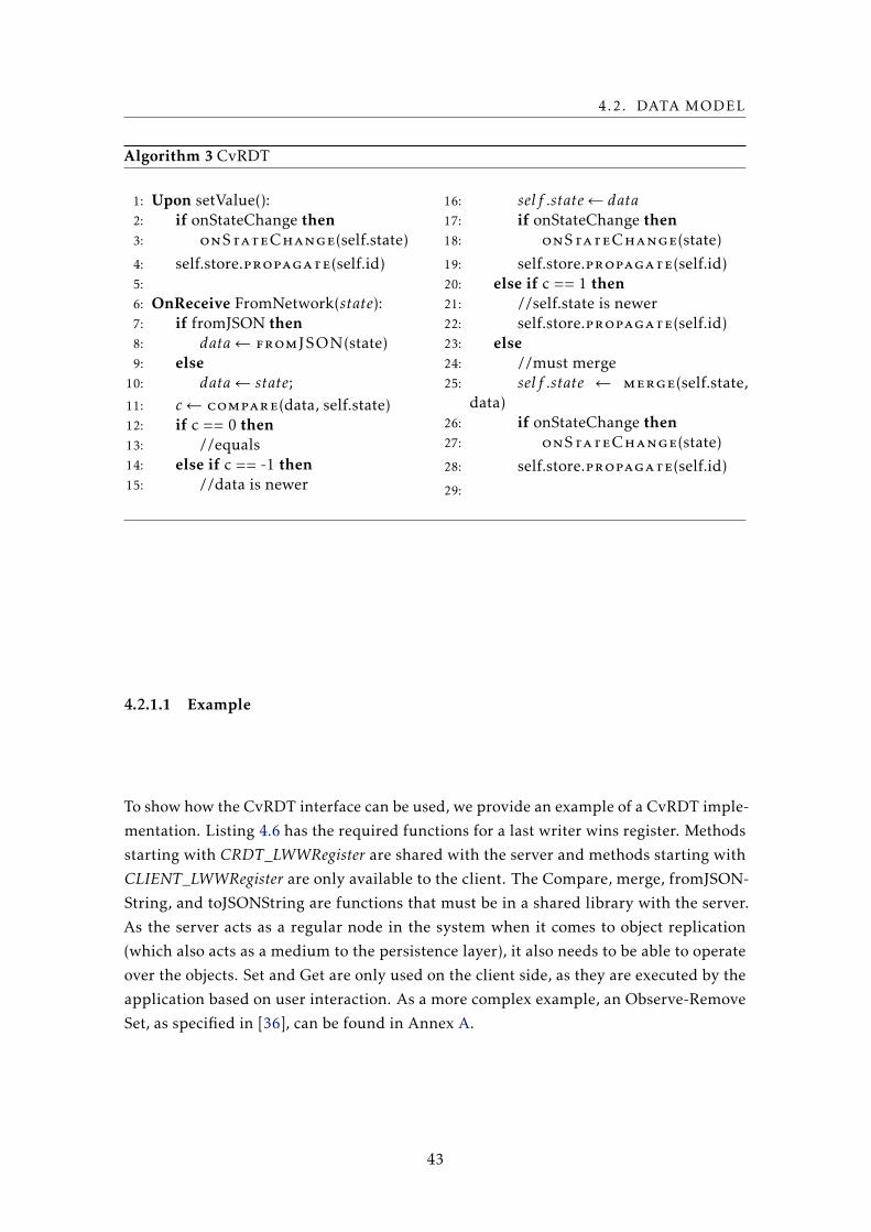
4.2. DATA MODEL
Algorithm 3 CvRDT
1: Upon setValue():2: if onStateChange then3: onStateChange(self.state)
4: self.store.propagate(self.id)5:
6: OnReceive FromNetwork(state):7: if fromJSON then8: data← fromJSON(state)9: else
10: data← state;11: c← compare(data, self.state)12: if c == 0 then13: //equals14: else if c == -1 then15: //data is newer
16: self .state← data17: if onStateChange then18: onStateChange(state)
19: self.store.propagate(self.id)20: else if c == 1 then21: //self.state is newer22: self.store.propagate(self.id)23: else24: //must merge25: self .state ← merge(self.state,
data)26: if onStateChange then27: onStateChange(state)
28: self.store.propagate(self.id)
29:
4.2.1.1 Example
To show how the CvRDT interface can be used, we provide an example of a CvRDT imple-
mentation. Listing 4.6 has the required functions for a last writer wins register. Methods
starting with CRDT_LWWRegister are shared with the server and methods starting with
CLIENT_LWWRegister are only available to the client. The Compare, merge, fromJSON-
String, and toJSONString are functions that must be in a shared library with the server.
As the server acts as a regular node in the system when it comes to object replication
(which also acts as a medium to the persistence layer), it also needs to be able to operate
over the objects. Set and Get are only used on the client side, as they are executed by the
application based on user interaction. As a more complex example, an Observe-Remove
Set, as specified in [36], can be found in Annex A.
43
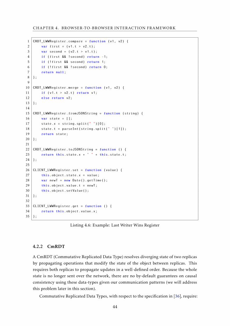
CHAPTER 4. BROWSER-TO-BROWSER INTERACTION FRAMEWORK
1 CRDT_LWWRegister.compare = function (v1, v2) {
2 var first = (v1.t > v2.t);
3 var second = (v2.t > v1.t);
4 if (first && !second) return -1;
5 if (!first && second) return 1;
6 if (!first && !second) return 0;
7 return null;
8 };
9
10 CRDT_LWWRegister.merge = function (v1, v2) {
11 if (v1.t > v2.t) return v1;
12 else return v2;
13 };
14
15 CRDT_LWWRegister.fromJSONString = function (string) {
16 var state = [];
17 state.x = string.split(" ")[0];
18 state.t = parseInt(string.split(" ")[1]);
19 return state;
20 };
21
22 CRDT_LWWRegister.toJSONString = function () {
23 return this.state.x + " " + this.state.t;
24 };
25
26 CLIENT_LWWRegister.set = function (value) {
27 this.object.state.x = value;
28 var newT = new Date().getTime();
29 this.object.value.t = newT;
30 this.object.setValue();
31 };
32
33 CLIENT_LWWRegister.get = function () {
34 return this.object.value.x;
35 };
Listing 4.6: Example: Last Writer Wins Register
4.2.2 CmRDT
A CmRDT (Commutative Replicated Data Type) resolves diverging state of two replicas
by propagating operations that modify the state of the object between replicas. This
requires both replicas to propagate updates in a well-defined order. Because the whole
state is no longer sent over the network, there are no by-default guarantees on causal
consistency using these data-types given our communication patterns (we will address
this problem later in this section).
Commutative Replicated Data Types, with respect to the specification in [36], require:
44
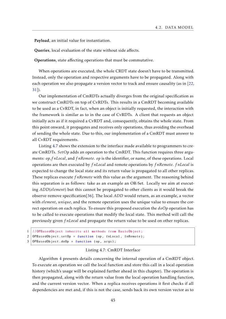
4.2. DATA MODEL
Payload, an initial value for instantiation.
Queries, local evaluation of the state without side affects.
Operations, state affecting operations that must be commutative.
When operations are executed, the whole CRDT state doesn’t have to be transmitted.
Instead, only the operation and respective arguments have to be propagated. Along with
each operation we also propagate a version vector to track and ensure causality (as in [22,
31]).
Our implementation of CmRDTs actually diverges from the original specification as
we construct CmRDTs on top of CvRDTs. This results in a CmRDT becoming available
to be used as a CvRDT, in fact, when an object is initially requested, the interaction with
the framework is similar as to in the case of CvRDTs. A client that requests an object
initially acts as if it required a CvRDT and, consequently, obtains the whole state. From
this point onward, it propagates and receives only operations, thus avoiding the overhead
of sending the whole state. Due to this, our implementation of a CmRDT must answer to
all CvRDT requirements.
Listing 4.7 shows the extension to the interface made available to programmers to cre-
ate CmRDTs. SetOp adds an operation to the CmRDT. This function requires three argu-
ments: op,f nLocal, and f nRemote. op is the identifier, or name, of these operations. Local
operations are then executed by f nLocal and remote operations by f nRemote. f nLocal is
expected to change the local state and its return value is propagated to all other replicas.
These replicas execute f nRemote with this value as the argument. The reasoning behind
this separation is as follows: take as an example an OR-Set. Locally we aim at execut-
ing ADD(element) but this cannot be propagated to other clients as it would break the
observe-remove specification[36]. The local ADD would return, as an example, a vector
with element, unique, and the remote operation uses the unique value to ensure the cor-
rect operation on each replica. To ensure this proposed execution the doOp operation has
to be called to execute operations that modify the local state. This method will call the
previously given f nLocal and propagate the return value to be used on other replicas.
1 //OPBasedObject inherits all methods from BasicObject;
2 OPBasedObject.setOp = function (op, fnLocal, fnRemote);
3 OPBasedObject.doOp = function (op, args);
Listing 4.7: CmRDT Interface
Algorithm 4 presents details concerning the internal operation of a CmRDT object.
To execute an operation we call the local function and store this call in a local operation
history (which’s usage will be explained further ahead in this chapter). The operation is
then propagated, along with the return value from the local operation handling function,
and the current version vector. When a replica receives operations it first checks if all
dependencies are met and, if this is not the case, sends back its own version vector as to
45
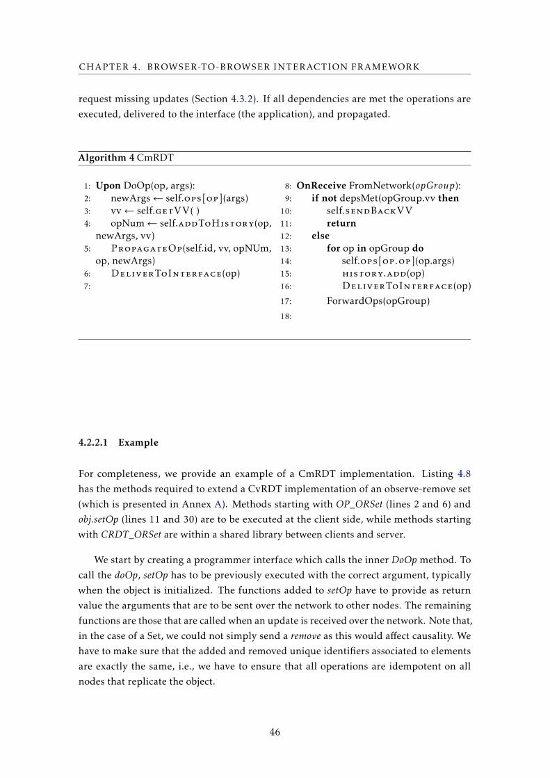
CHAPTER 4. BROWSER-TO-BROWSER INTERACTION FRAMEWORK
request missing updates (Section 4.3.2). If all dependencies are met the operations are
executed, delivered to the interface (the application), and propagated.
Algorithm 4 CmRDT
1: Upon DoOp(op, args):2: newArgs← self.ops[op](args)3: vv← self.getVV( )4: opNum← self.addToHistory(op,
newArgs, vv)5: PropagateOp(self.id, vv, opNUm,
op, newArgs)6: DeliverToInterface(op)7:
8: OnReceive FromNetwork(opGroup):9: if not depsMet(opGroup.vv then
10: self.sendBackVV
11: return12: else13: for op in opGroup do14: self.ops[op.op](op.args)15: history.add(op)16: DeliverToInterface(op)
17: ForwardOps(opGroup)
18:
4.2.2.1 Example
For completeness, we provide an example of a CmRDT implementation. Listing 4.8
has the methods required to extend a CvRDT implementation of an observe-remove set
(which is presented in Annex A). Methods starting with OP_ORSet (lines 2 and 6) and
obj.setOp (lines 11 and 30) are to be executed at the client side, while methods starting
with CRDT_ORSet are within a shared library between clients and server.
We start by creating a programmer interface which calls the inner DoOp method. To
call the doOp, setOp has to be previously executed with the correct argument, typically
when the object is initialized. The functions added to setOp have to provide as return
value the arguments that are to be sent over the network to other nodes. The remaining
functions are those that are called when an update is received over the network. Note that,
in the case of a Set, we could not simply send a remove as this would affect causality. We
have to make sure that the added and removed unique identifiers associated to elements
are exactly the same, i.e., we have to ensure that all operations are idempotent on all
nodes that replicate the object.
46
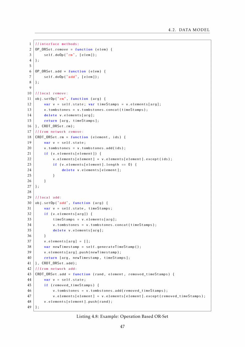
4.2. DATA MODEL
1 //interface methods:
2 OP_ORSet.remove = function (elem) {
3 self.doOp("rm", [elem]);
4 };
5
6 OP_ORSet.add = function (elem) {
7 self.doOp("add", [elem]);
8 };
9
10 //local remove:
11 obj.setOp("rm", function (arg) {
12 var v = self.state; var timeStamps = v.elements[arg];
13 v.tombstones = v.tombstones.concat(timeStamps);
14 delete v.elements[arg];
15 return [arg, timeStamps];
16 }, CRDT_ORSet.rm);
17 //from network remove:
18 CRDT_ORSet.rm = function (element, ids) {
19 var v = self.state;
20 v.tombstones = v.tombstones.add(ids);
21 if (v.elements[element]) {
22 v.elements[element] = v.elements[element].except(ids);
23 if (v.elements[element].length == 0) {
24 delete v.elements[element];
25 }
26 }
27 };
28
29 //local add:
30 obj.setOp("add", function (arg) {
31 var v = self.state, timeStamps;
32 if (v.elements[arg]) {
33 timeStamps = v.elements[arg];
34 v.tombstones = v.tombstones.concat(timeStamps);
35 delete v.elements[arg];
36 }
37 v.elements[arg] = [];
38 var newTimestamp = self.generateTimeStamp();
39 v.elements[arg].push(newTimestamp);
40 return [arg, newTimestamp, timeStamps];
41 }, CRDT_ORSet.add);
42 //from network add:
43 CRDT_ORSet.add = function (rand, element, removed_timeStamps) {
44 var v = self.state;
45 if (removed_timeStamps) {
46 v.tombstones = v.tombstones.add(removed_timeStamps);
47 v.elements[element] = v.elements[element].except(removed_timeStamps);
48 v.elements[element].push(rand);
49 };
Listing 4.8: Example: Operation Based OR-Set
47
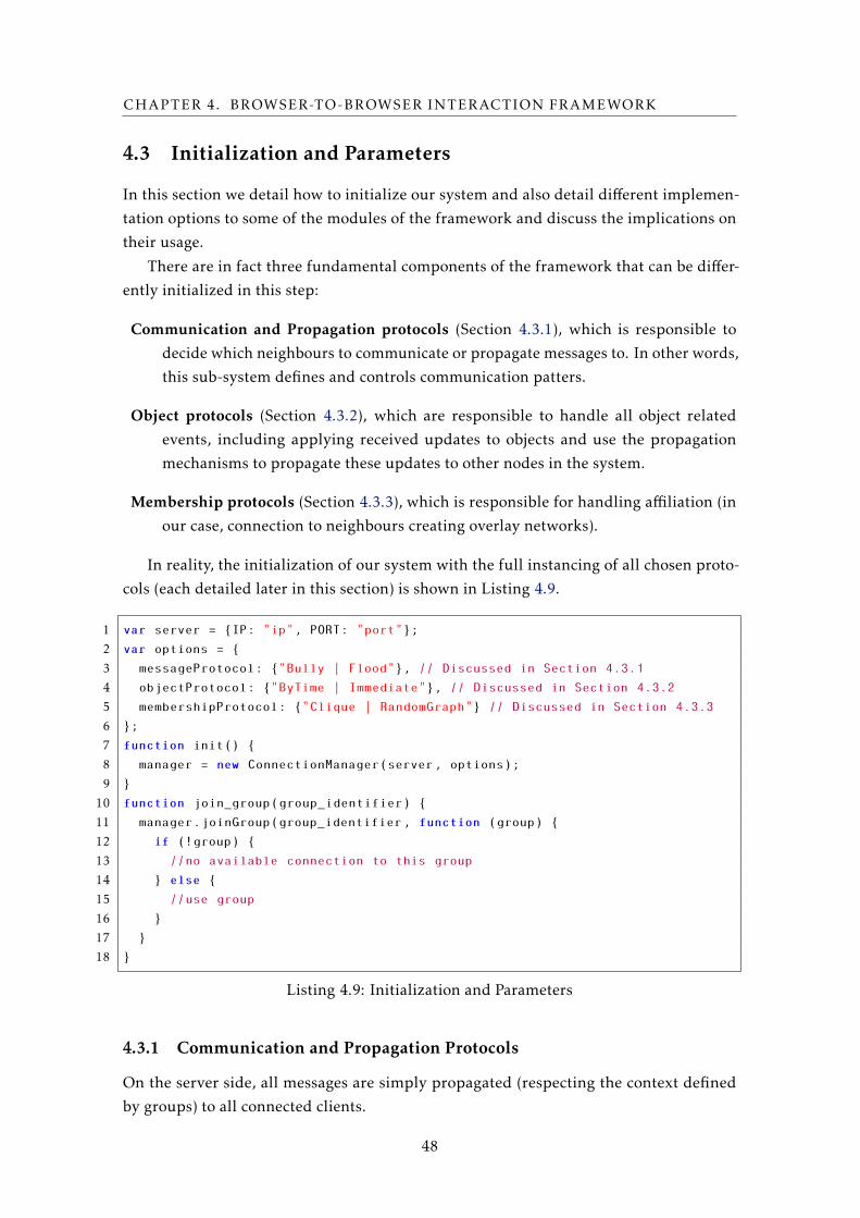
CHAPTER 4. BROWSER-TO-BROWSER INTERACTION FRAMEWORK
4.3 Initialization and Parameters
In this section we detail how to initialize our system and also detail different implemen-
tation options to some of the modules of the framework and discuss the implications on
their usage.
There are in fact three fundamental components of the framework that can be differ-
ently initialized in this step:
Communication and Propagation protocols (Section 4.3.1), which is responsible to
decide which neighbours to communicate or propagate messages to. In other words,
this sub-system defines and controls communication patters.
Object protocols (Section 4.3.2), which are responsible to handle all object related
events, including applying received updates to objects and use the propagation
mechanisms to propagate these updates to other nodes in the system.
Membership protocols (Section 4.3.3), which is responsible for handling affiliation (in
our case, connection to neighbours creating overlay networks).
In reality, the initialization of our system with the full instancing of all chosen proto-
cols (each detailed later in this section) is shown in Listing 4.9.
1 var server = {IP: "ip", PORT: "port"};
2 var options = {
3 messageProtocol: {"Bully | Flood"}, // Discussed in Section 4.3.1
4 objectProtocol: {"ByTime | Immediate"}, // Discussed in Section 4.3.2
5 membershipProtocol: {"Clique | RandomGraph"} // Discussed in Section 4.3.3
6 };
7 function init() {
8 manager = new ConnectionManager(server, options);
9 }
10 function join_group(group_identifier) {
11 manager.joinGroup(group_identifier, function (group) {
12 if (!group) {
13 //no available connection to this group
14 } else {
15 //use group
16 }
17 }
18 }
Listing 4.9: Initialization and Parameters
4.3.1 Communication and Propagation Protocols
On the server side, all messages are simply propagated (respecting the context defined
by groups) to all connected clients.
48
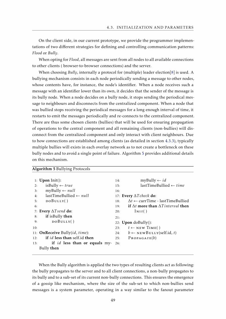
4.3. INITIALIZATION AND PARAMETERS
On the client side, in our current prototype, we provide the programmer implemen-
tations of two different strategies for defining and controlling communication patterns:
Flood or Bully.
When opting for Flood, all messages are sent from all nodes to all available connections
to other clients ( browser-to-browser connections) and the server.
When choosing Bully, internally a protocol for (multiple) leader election[8] is used. A
bullying mechanism consists in each node periodically sending a message to other nodes,
whose contents have, for instance, the node’s identifier. When a node receives such a
message with an identifier lower than its own, it decides that the sender of the message is
its bully node. When a node decides on a bully node, it stops sending the periodical mes-
sage to neighbours and disconnects from the centralized component. When a node that
was bullied stops receiving the periodical messages for a long enough interval of time, it
restarts to emit the messages periodically and re-connects to the centralized component.
There are thus some chosen clients (bullies) that will be used for ensuring propagation
of operations to the central component and all remaining clients (non-bullies) will dis-
connect from the centralized component and only interact with client neighbours. Due
to how connections are established among clients (as detailed in section 4.3.3), typically
multiple bullies will exists in each overlay network as to not create a bottleneck on these
bully nodes and to avoid a single point of failure. Algorithm 5 provides additional details
on this mechanism.
Algorithm 5 Bullying Protocols
1: Upon Init():2: isBully← true3: myBully← null4: lastTimeBullied← null5: doBully( )6:
7: Every ∆T send do:8: if isBully then9: doBully( )
10:
11: OnReceive Bully(id, time):12: if id less than self.id then13: if id less than or equals my-
Bully then
14: myBully← id15: lastTimeBullied← time16:
17: Every ∆T check do:18: ∆t← currTime - lastTimeBullied19: if ∆t more than ∆T interval then20: Init( )
21:
22: Upon doBully():23: t← new Time( )24: b← newBully(self.id, t)25: Propagate(b)26:
When the Bully algorithm is applied the two types of resulting clients act as following:
the bully propagates to the server and to all client connections, a non-bully propagates to
its bully and to a sub-set of its current non-bully connections. This ensures the emergence
of a gossip like mechanism, where the size of the sub-set to which non-bullies send
messages is a system parameter, operating in a way similar to the fanout parameter
49
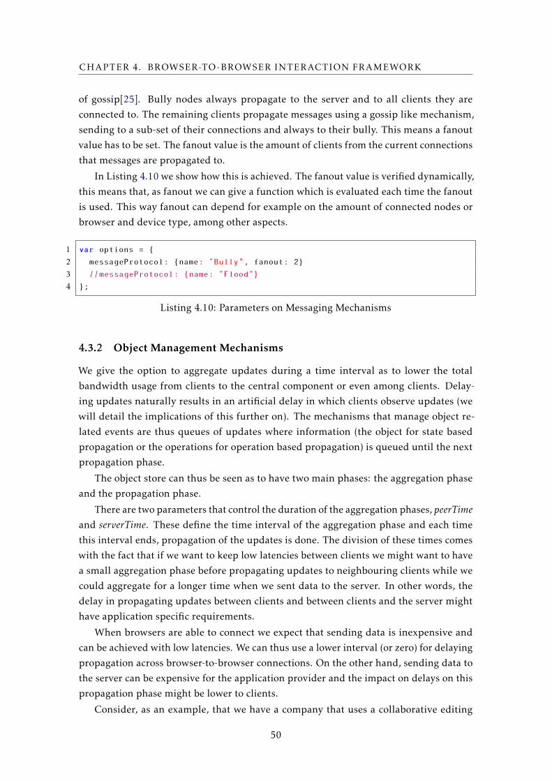
CHAPTER 4. BROWSER-TO-BROWSER INTERACTION FRAMEWORK
of gossip[25]. Bully nodes always propagate to the server and to all clients they are
connected to. The remaining clients propagate messages using a gossip like mechanism,
sending to a sub-set of their connections and always to their bully. This means a fanout
value has to be set. The fanout value is the amount of clients from the current connections
that messages are propagated to.
In Listing 4.10 we show how this is achieved. The fanout value is verified dynamically,
this means that, as fanout we can give a function which is evaluated each time the fanout
is used. This way fanout can depend for example on the amount of connected nodes or
browser and device type, among other aspects.
1 var options = {
2 messageProtocol: {name: "Bully", fanout: 2}
3 //messageProtocol: {name: "Flood"}
4 };
Listing 4.10: Parameters on Messaging Mechanisms
4.3.2 Object Management Mechanisms
We give the option to aggregate updates during a time interval as to lower the total
bandwidth usage from clients to the central component or even among clients. Delay-
ing updates naturally results in an artificial delay in which clients observe updates (we
will detail the implications of this further on). The mechanisms that manage object re-
lated events are thus queues of updates where information (the object for state based
propagation or the operations for operation based propagation) is queued until the next
propagation phase.
The object store can thus be seen as to have two main phases: the aggregation phase
and the propagation phase.
There are two parameters that control the duration of the aggregation phases, peerTimeand serverTime. These define the time interval of the aggregation phase and each time
this interval ends, propagation of the updates is done. The division of these times comes
with the fact that if we want to keep low latencies between clients we might want to have
a small aggregation phase before propagating updates to neighbouring clients while we
could aggregate for a longer time when we sent data to the server. In other words, the
delay in propagating updates between clients and between clients and the server might
have application specific requirements.
When browsers are able to connect we expect that sending data is inexpensive and
can be achieved with low latencies. We can thus use a lower interval (or zero) for delaying
propagation across browser-to-browser connections. On the other hand, sending data to
the server can be expensive for the application provider and the impact on delays on this
propagation phase might be lower to clients.
Consider, as an example, that we have a company that uses a collaborative editing
50
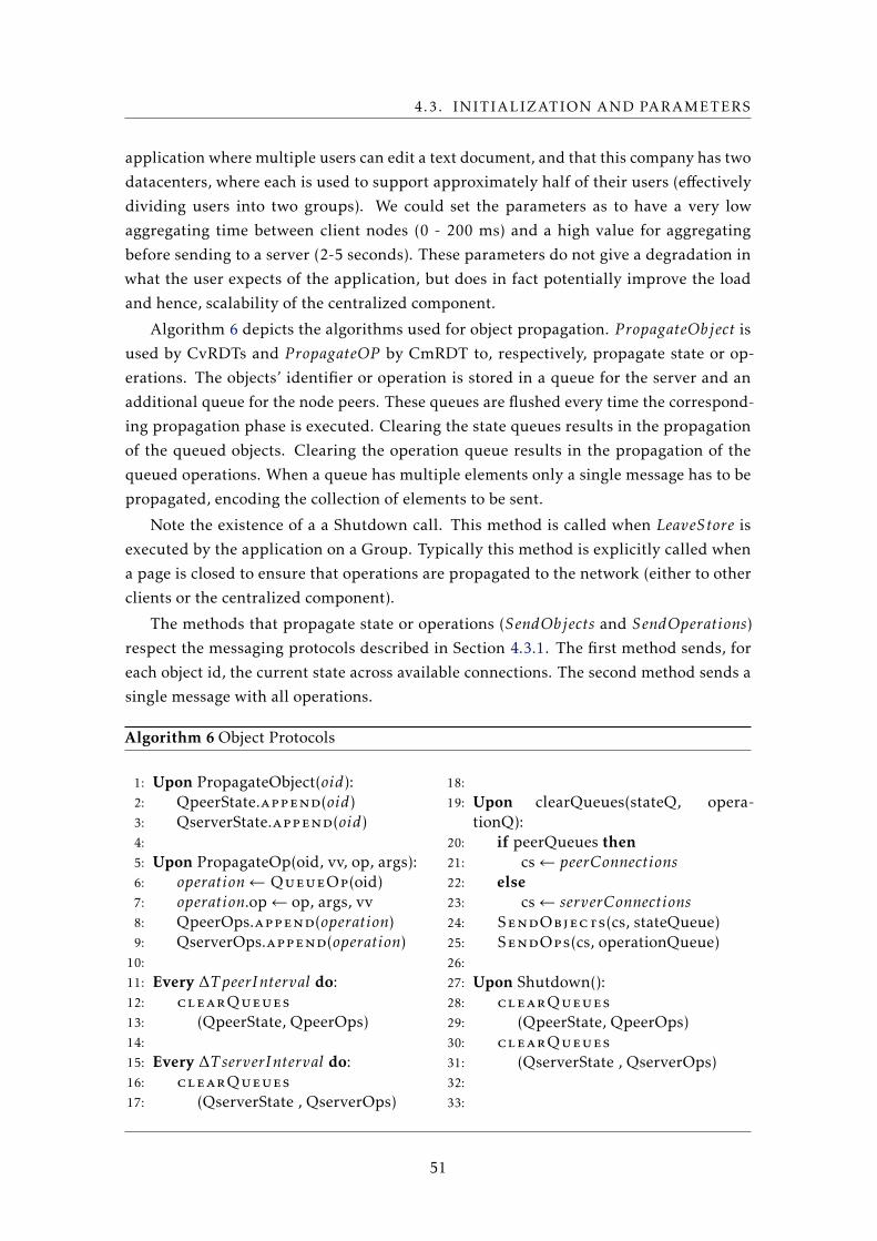
4.3. INITIALIZATION AND PARAMETERS
application where multiple users can edit a text document, and that this company has two
datacenters, where each is used to support approximately half of their users (effectively
dividing users into two groups). We could set the parameters as to have a very low
aggregating time between client nodes (0 - 200 ms) and a high value for aggregating
before sending to a server (2-5 seconds). These parameters do not give a degradation in
what the user expects of the application, but does in fact potentially improve the load
and hence, scalability of the centralized component.
Algorithm 6 depicts the algorithms used for object propagation. P ropagateObject is
used by CvRDTs and P ropagateOP by CmRDT to, respectively, propagate state or op-
erations. The objects’ identifier or operation is stored in a queue for the server and an
additional queue for the node peers. These queues are flushed every time the correspond-
ing propagation phase is executed. Clearing the state queues results in the propagation
of the queued objects. Clearing the operation queue results in the propagation of the
queued operations. When a queue has multiple elements only a single message has to be
propagated, encoding the collection of elements to be sent.
Note the existence of a a Shutdown call. This method is called when LeaveStore is
executed by the application on a Group. Typically this method is explicitly called when
a page is closed to ensure that operations are propagated to the network (either to other
clients or the centralized component).
The methods that propagate state or operations (SendObjects and SendOperations)
respect the messaging protocols described in Section 4.3.1. The first method sends, for
each object id, the current state across available connections. The second method sends a
single message with all operations.
Algorithm 6 Object Protocols
1: Upon PropagateObject(oid):2: QpeerState.append(oid)3: QserverState.append(oid)4:
5: Upon PropagateOp(oid, vv, op, args):6: operation← QueueOp(oid)7: operation.op← op, args, vv8: QpeerOps.append(operation)9: QserverOps.append(operation)
10:
11: Every ∆T peerInterval do:12: clearQueues
13: (QpeerState, QpeerOps)14:
15: Every ∆T serverInterval do:16: clearQueues
17: (QserverState , QserverOps)
18:
19: Upon clearQueues(stateQ, opera-tionQ):
20: if peerQueues then21: cs← peerConnections22: else23: cs← serverConnections24: SendObjects(cs, stateQueue)25: SendOps(cs, operationQueue)26:
27: Upon Shutdown():28: clearQueues
29: (QpeerState, QpeerOps)30: clearQueues
31: (QserverState , QserverOps)32:
33:
51
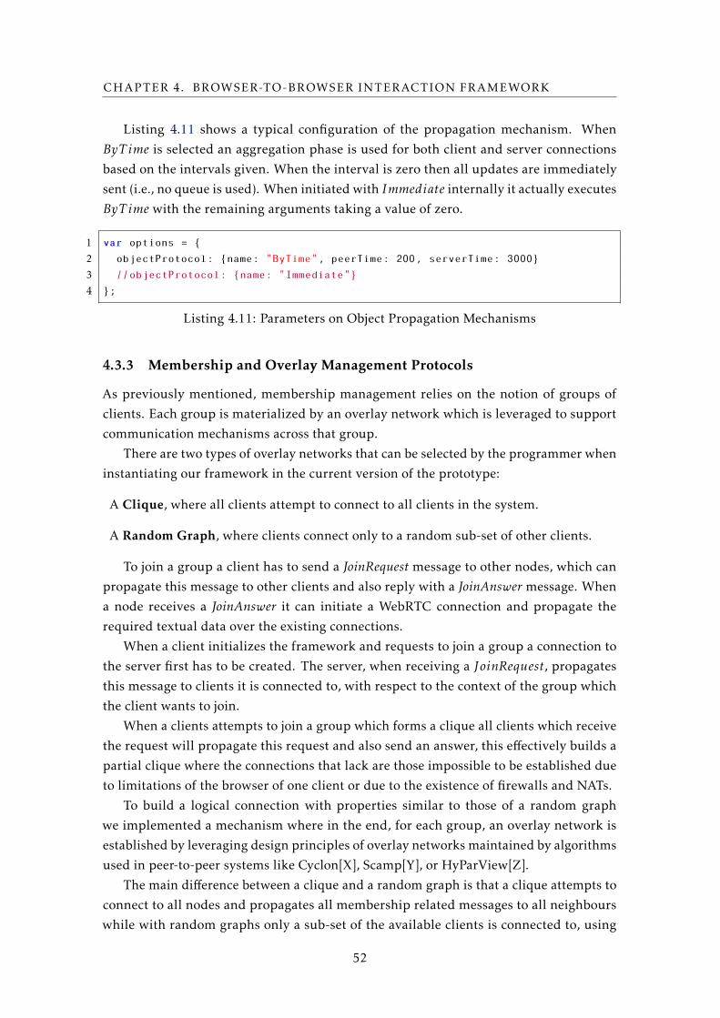
CHAPTER 4. BROWSER-TO-BROWSER INTERACTION FRAMEWORK
Listing 4.11 shows a typical configuration of the propagation mechanism. When
ByT ime is selected an aggregation phase is used for both client and server connections
based on the intervals given. When the interval is zero then all updates are immediately
sent (i.e., no queue is used). When initiated with Immediate internally it actually executes
ByT ime with the remaining arguments taking a value of zero.
1 var options = {
2 objectProtocol: {name: "ByTime", peerTime: 200, serverTime: 3000}
3 //objectProtocol: {name: "Immediate"}
4 };
Listing 4.11: Parameters on Object Propagation Mechanisms
4.3.3 Membership and Overlay Management Protocols
As previously mentioned, membership management relies on the notion of groups of
clients. Each group is materialized by an overlay network which is leveraged to support
communication mechanisms across that group.
There are two types of overlay networks that can be selected by the programmer when
instantiating our framework in the current version of the prototype:
A Clique, where all clients attempt to connect to all clients in the system.
A Random Graph, where clients connect only to a random sub-set of other clients.
To join a group a client has to send a JoinRequest message to other nodes, which can
propagate this message to other clients and also reply with a JoinAnswer message. When
a node receives a JoinAnswer it can initiate a WebRTC connection and propagate the
required textual data over the existing connections.
When a client initializes the framework and requests to join a group a connection to
the server first has to be created. The server, when receiving a JoinRequest, propagates
this message to clients it is connected to, with respect to the context of the group which
the client wants to join.
When a clients attempts to join a group which forms a clique all clients which receive
the request will propagate this request and also send an answer, this effectively builds a
partial clique where the connections that lack are those impossible to be established due
to limitations of the browser of one client or due to the existence of firewalls and NATs.
To build a logical connection with properties similar to those of a random graph
we implemented a mechanism where in the end, for each group, an overlay network is
established by leveraging design principles of overlay networks maintained by algorithms
used in peer-to-peer systems like Cyclon[X], Scamp[Y], or HyParView[Z].
The main difference between a clique and a random graph is that a clique attempts to
connect to all nodes and propagates all membership related messages to all neighbours
while with random graphs only a sub-set of the available clients is connected to, using
52
4.3. INITIALIZATION AND PARAMETERS
random walks over the existing logical network links to build a random graph. A random
walk in this context is the propagation of a message over the network (in our case a
JoinRequest) in a fixed maximum number of steps. At each propagation point selecting
the next step for the message is made at random from the set of neighbours of the node
forwarding the message.
The algorithm, detailed in Algorithm 7, requires the following parameters to be set:
min, which controls the minimum browser-to-browser connections a client strives to
maintain; max, which controls the maximum acceptable number of connections; initial_n,
the amount of connections a client requests when joining a group; initial_ttl, the time-
to-live value of random walks; meta, time interval to send meta-data to peers (which’s
usage will be clear next); timeout, time interval to check for maximum and minimum
connection count; and rand, the probability factor for connections (as explained next).
The way this mechanism works is as follows: first the client establishes a connection
to the server. The client then sends a JoinRequest over this connection, adding to the
message a time-to-live (T T L) for random walks, and a number, N , which represents the
number of connections the node wishes to establish. The server will propagate this mes-
sage to a maximum of N nodes, modifying the N value of the message as to divide N
between all clients, and decrements the TTL value (as an example, the propagation of a
request with N equal to eight being sent to four nodes, each receives a request with a N
value of two). When a client node receives a JoinRequest it acts, in order of preference,
as follows: i) if the current amount of connections is below the minimum specified then
send a JoinAnswer; ii) if the request’s TTL is zero then send a JoinAnswer; iii) if current
connection count is below the maximum then the client sends a JoinAnswer with a given
probability which is a configuration parameter (rand). If the value returned by this func-
tion falls below a certain threshold (which can be changed by parameter) the TTL of the
message is decremented and, if a JoinAnswer was send (i.e., the new client was included
as overlay neighbour of the current node), N is also decremented. Finally, the request is
propagated to at most N nodes, dividing N by the number of nodes to which the message
is propagated to.
To ensure that the minimum amount of connections is maintained, an interval is
specified to check the current connection count. Every interval of timeout duration, each
node verifies the number of overlay neighbours it owns currently. If this count falls below
the minimum then a new JoinRequest is sent, as previously described, but with N equal to
max minus the current amount of neighbours. If the count is above the maximum, then a
peer is chosen to be disconnected and removed as neighbour. To ensure we do not remove
the peers that would immediately have to re-initiate new connections to clients we opt to
remove the best connected peer from the connected peers.
To be able to chose a best connected peer, each peer sends, each meta milliseconds, a
message with the count of number of peer-to-peer connections and server connections it
has. The peer to be removed is the one with the most browser-to-browser connections,
where the count of server connections is used as disambiguation. If no distinction can be
53
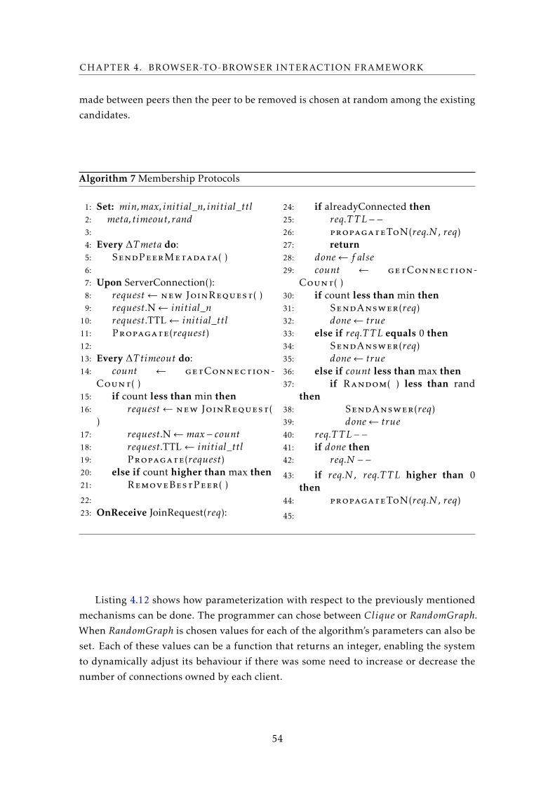
CHAPTER 4. BROWSER-TO-BROWSER INTERACTION FRAMEWORK
made between peers then the peer to be removed is chosen at random among the existing
candidates.
Algorithm 7 Membership Protocols
1: Set: min,max, initial_n, initial_ttl2: meta, timeout, rand3:
4: Every ∆Tmeta do:5: SendPeerMetadata( )6:
7: Upon ServerConnection():8: request← new JoinRequest( )9: request.N← initial_n
10: request.TTL← initial_ttl11: Propagate(request)12:
13: Every ∆T timeout do:14: count ← getConnection-
Count( )15: if count less than min then16: request← new JoinRequest(
)17: request.N← max − count18: request.TTL← initial_ttl19: Propagate(request)20: else if count higher than max then21: RemoveBestPeer( )
22:
23: OnReceive JoinRequest(req):
24: if alreadyConnected then25: req.T T L−−26: propagateToN(req.N , req)27: return28: done← f alse29: count ← getConnection-
Count( )30: if count less than min then31: SendAnswer(req)32: done← true33: else if req.T T L equals 0 then34: SendAnswer(req)35: done← true36: else if count less than max then37: if Random( ) less than rand
then38: SendAnswer(req)39: done← true40: req.T T L−−41: if done then42: req.N −−43: if req.N , req.T T L higher than 0
then44: propagateToN(req.N , req)
45:
Listing 4.12 shows how parameterization with respect to the previously mentioned
mechanisms can be done. The programmer can chose between Clique or RandomGraph.
When RandomGraph is chosen values for each of the algorithm’s parameters can also be
set. Each of these values can be a function that returns an integer, enabling the system
to dynamically adjust its behaviour if there was some need to increase or decrease the
number of connections owned by each client.
54
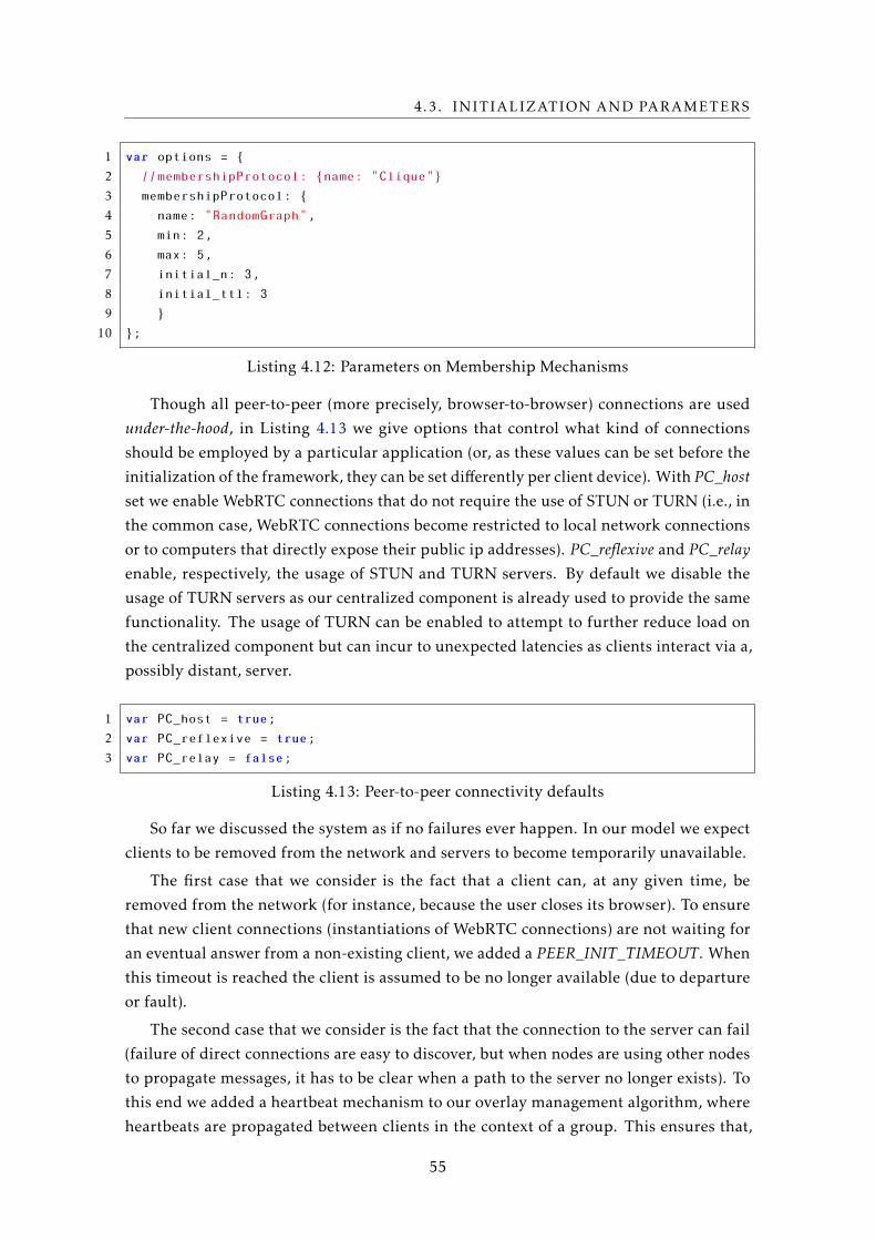
4.3. INITIALIZATION AND PARAMETERS
1 var options = {
2 //membershipProtocol: {name: "Clique"}
3 membershipProtocol: {
4 name: "RandomGraph",
5 min: 2,
6 max: 5,
7 initial_n: 3,
8 initial_ttl: 3
9 }
10 };
Listing 4.12: Parameters on Membership Mechanisms
Though all peer-to-peer (more precisely, browser-to-browser) connections are used
under-the-hood, in Listing 4.13 we give options that control what kind of connections
should be employed by a particular application (or, as these values can be set before the
initialization of the framework, they can be set differently per client device). With PC_hostset we enable WebRTC connections that do not require the use of STUN or TURN (i.e., in
the common case, WebRTC connections become restricted to local network connections
or to computers that directly expose their public ip addresses). PC_reflexive and PC_relayenable, respectively, the usage of STUN and TURN servers. By default we disable the
usage of TURN servers as our centralized component is already used to provide the same
functionality. The usage of TURN can be enabled to attempt to further reduce load on
the centralized component but can incur to unexpected latencies as clients interact via a,
possibly distant, server.
1 var PC_host = true;
2 var PC_reflexive = true;
3 var PC_relay = false;
Listing 4.13: Peer-to-peer connectivity defaults
So far we discussed the system as if no failures ever happen. In our model we expect
clients to be removed from the network and servers to become temporarily unavailable.
The first case that we consider is the fact that a client can, at any given time, be
removed from the network (for instance, because the user closes its browser). To ensure
that new client connections (instantiations of WebRTC connections) are not waiting for
an eventual answer from a non-existing client, we added a PEER_INIT_TIMEOUT. When
this timeout is reached the client is assumed to be no longer available (due to departure
or fault).
The second case that we consider is the fact that the connection to the server can fail
(failure of direct connections are easy to discover, but when nodes are using other nodes
to propagate messages, it has to be clear when a path to the server no longer exists). To
this end we added a heartbeat mechanism to our overlay management algorithm, where
heartbeats are propagated between clients in the context of a group. This ensures that,
55
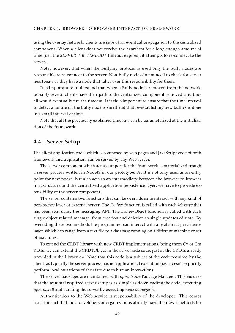
CHAPTER 4. BROWSER-TO-BROWSER INTERACTION FRAMEWORK
using the overlay network, clients are sure of an eventual propagation to the centralized
component. When a client does not receive the heartbeat for a long enough amount of
time (i.e., the SERVER_HB_TIMEOUT timeout expires), it attempts to re-connect to the
server.
Note, however, that when the Bullying protocol is used only the bully nodes are
responsible to re-connect to the server. Non-bully nodes do not need to check for server
heartbeats as they have a node that takes over this responsibility for them.
It is important to understand that when a Bully node is removed from the network,
possibly several clients have their path to the centralized component removed, and thus
all would eventually fire the timeout. It is thus important to ensure that the time interval
to detect a failure on the bully node is small and that re-establishing new bullies is done
in a small interval of time.
Note that all the previously explained timeouts can be parameterized at the initializa-
tion of the framework.
4.4 Server Setup
The client application code, which is composed by web pages and JavaScript code of both
framework and application, can be served by any Web server.
The server component which act as support for the framework is materialized trough
a server process written in NodeJS in our prototype. As it is not only used as an entry
point for new nodes, but also acts as an intermediary between the browser-to-browser
infrastructure and the centralized application persistence layer, we have to provide ex-
tensibility of the server component.
The server contains two functions that can be overridden to interact with any kind of
persistence layer or external server. The Deliver function is called with each Message that
has been sent using the messaging API. The DeliverObject function is called with each
single object related message, from creation and deletion to single updates of state. By
overriding these two methods the programmer can interact with any abstract persistence
layer, which can range from a text file to a database running on a different machine or set
of machines.
To extend the CRDT library with new CRDT implementations, being them Cv or Cm
RDTs, we can extend the CRDTObject in the server side code, just as the CRDTs already
provided in the library do. Note that this code is a sub-set of the code required by the
client, as typically the server process has no applicational execution (i.e., doesn’t explicitly
perform local mutations of the state due to human interaction).
The server packages are maintained with npm, Node Package Manager. This ensures
that the minimal required server setup is as simple as downloading the code, executing
npm install and running the server by executing node manager.js.Authentication to the Web service is responsability of the developer. This comes
from the fact that most developers or organizations already have their own methods for
56
4.5. IMPLEMENTATION DETAILS
authenticating clients across their applications. We do however intend, in future work, to
add support that simplifies the extension of our framework to add simple authentication
mechanisms.
4.5 Implementation Details
In this section we present some details of our implementation of the framework proto-
type that may have a minimal, albeit visible, effect on measurements performed in our
experimental work, reported in the next chapter. Our implementation, including code
of the centralized component, consists of 5,526 lines of JavaScript. Using an automated
JavaScript code minimizing tool2, the client side code results in a 39 KB size file. This
implies that an additional 39KB can be downloaded from the web server when loading
the web application into the browser.
To connect with the B2BServer we use WebSockets, available in all major browsers.
To connect from browser-to-browser we use WebRTC, as previously explained.
All communication between clients and server nodes is performed over JSON (JavaScript
Object Notation), as it is easy for humans to read and computers to generate, being widely
used in JavaScript applications.
All data that is sent over the network is compressed, which is expected to greatly
reduce network traffic. To compress messages we call compress and decompress before
sending messages. Our current implementation uses a LZMA implementation3 and can
be exchanged with any other compression method by overriding the compress and decom-press functions on both the client and server.
2Namely the tool available at https://github.com/mishoo/UglifyJS2.3In particular, the one available at http://github.com/nmrugg/LZMA-JS.
57

Chapter
5Evaluation
In this chapter we present the evaluation of our work. In Section 5.1 we show results that
evaluate alternatives to the materialization of modules in our framework using Micro-
Benchmarks. As our main intent is to show the feasibility of using browser-to-browser
as a communication model for richer applications, in Section 5.2 we show results of
the comparison of our solution to an extablished industry solution using the traditional
communication model (client-server).
All experiments reported here were conducted in a setting that uses server and clients
nodes running in a cloud platform (Amazon AWS).
5.1 Micro-Benchmarks
In this section we show results of micro-benchmarks over different implementation al-
ternatives in modules of our system. We also present a series of micro-benchmarks to
evaluate specific functionalities of the system. These benchmarks help us ensure that the
most adequate implementation and parameters are used for a valid comparison with an
industry solution.
We start off, in Section 5.1.1, by showing the impact of adding support for the prop-
agation of operations of CRDTs instead of propagating the whole state (i.e., the use of
CvRDT versus CmRDT). In Section 5.1.2 we compare the impact of using different over-
lay networks. In Section 5.1.3 we evaluate a specific overlay network’s properties (an
unstructured overlay network that establishes a random graph across nodes). In Section
5.1.4 we briefly evaluate the support for disconnection and other execution environments.
59
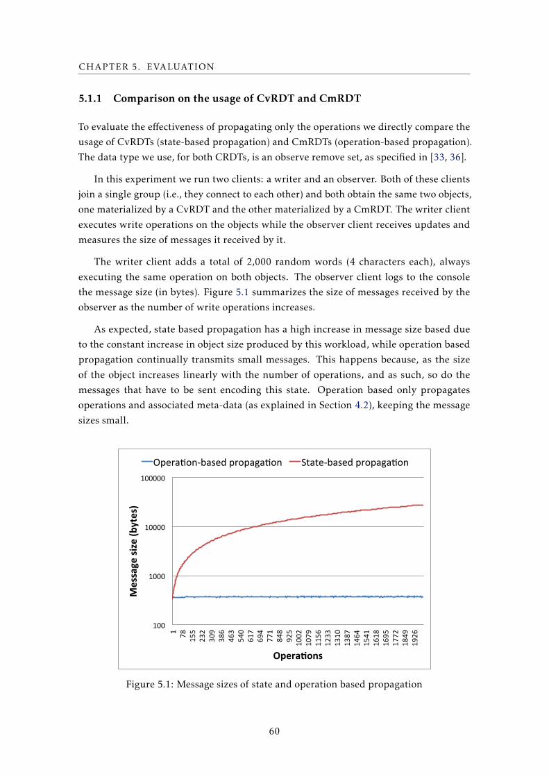
CHAPTER 5. EVALUATION
5.1.1 Comparison on the usage of CvRDT and CmRDT
To evaluate the effectiveness of propagating only the operations we directly compare the
usage of CvRDTs (state-based propagation) and CmRDTs (operation-based propagation).
The data type we use, for both CRDTs, is an observe remove set, as specified in [33, 36].
In this experiment we run two clients: a writer and an observer. Both of these clients
join a single group (i.e., they connect to each other) and both obtain the same two objects,
one materialized by a CvRDT and the other materialized by a CmRDT. The writer client
executes write operations on the objects while the observer client receives updates and
measures the size of messages it received by it.
The writer client adds a total of 2,000 random words (4 characters each), always
executing the same operation on both objects. The observer client logs to the console
the message size (in bytes). Figure 5.1 summarizes the size of messages received by the
observer as the number of write operations increases.
As expected, state based propagation has a high increase in message size based due
to the constant increase in object size produced by this workload, while operation based
propagation continually transmits small messages. This happens because, as the size
of the object increases linearly with the number of operations, and as such, so do the
messages that have to be sent encoding this state. Operation based only propagates
operations and associated meta-data (as explained in Section 4.2), keeping the message
sizes small.
100#
1000#
10000#
100000#
1# 78#
155#
232#
309#
386#
463#
540#
617#
694#
771#
848#
925#
1002#
1079#
1156#
1233#
1310#
1387#
1464#
1541#
1618#
1695#
1772#
1849#
1926#
Message&size&(b
ytes)&
Opera1ons&
Opera1on4based#propaga1on# State4based#propaga1on#
Figure 5.1: Message sizes of state and operation based propagation
60
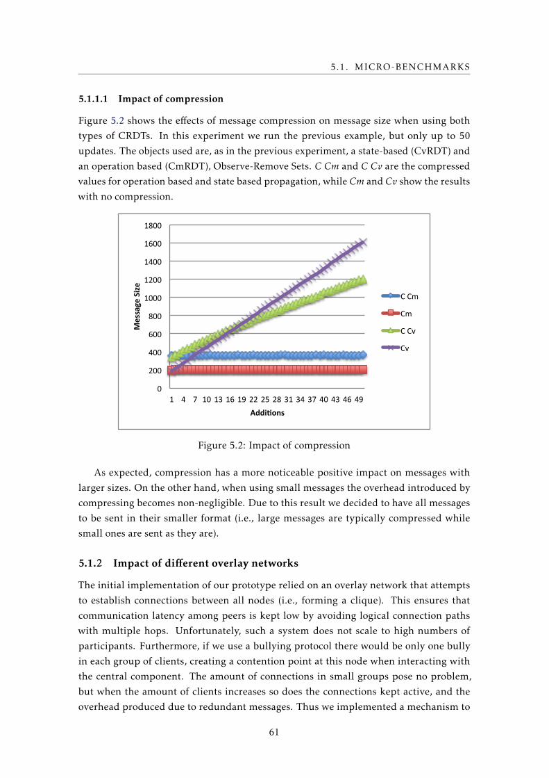
5.1. MICRO-BENCHMARKS
5.1.1.1 Impact of compression
Figure 5.2 shows the effects of message compression on message size when using both
types of CRDTs. In this experiment we run the previous example, but only up to 50
updates. The objects used are, as in the previous experiment, a state-based (CvRDT) and
an operation based (CmRDT), Observe-Remove Sets. C Cm and C Cv are the compressed
values for operation based and state based propagation, while Cm and Cv show the results
with no compression.
0
200
400
600
800
1000
1200
1400
1600
1800
1 4 7 10 13 16 19 22 25 28 31 34 37 40 43 46 49
Message Size
Addi,ons
C Cm
Cm
C Cv
Cv
Figure 5.2: Impact of compression
As expected, compression has a more noticeable positive impact on messages with
larger sizes. On the other hand, when using small messages the overhead introduced by
compressing becomes non-negligible. Due to this result we decided to have all messages
to be sent in their smaller format (i.e., large messages are typically compressed while
small ones are sent as they are).
5.1.2 Impact of different overlay networks
The initial implementation of our prototype relied on an overlay network that attempts
to establish connections between all nodes (i.e., forming a clique). This ensures that
communication latency among peers is kept low by avoiding logical connection paths
with multiple hops. Unfortunately, such a system does not scale to high numbers of
participants. Furthermore, if we use a bullying protocol there would be only one bully
in each group of clients, creating a contention point at this node when interacting with
the central component. The amount of connections in small groups pose no problem,
but when the amount of clients increases so does the connections kept active, and the
overhead produced due to redundant messages. Thus we implemented a mechanism to
61
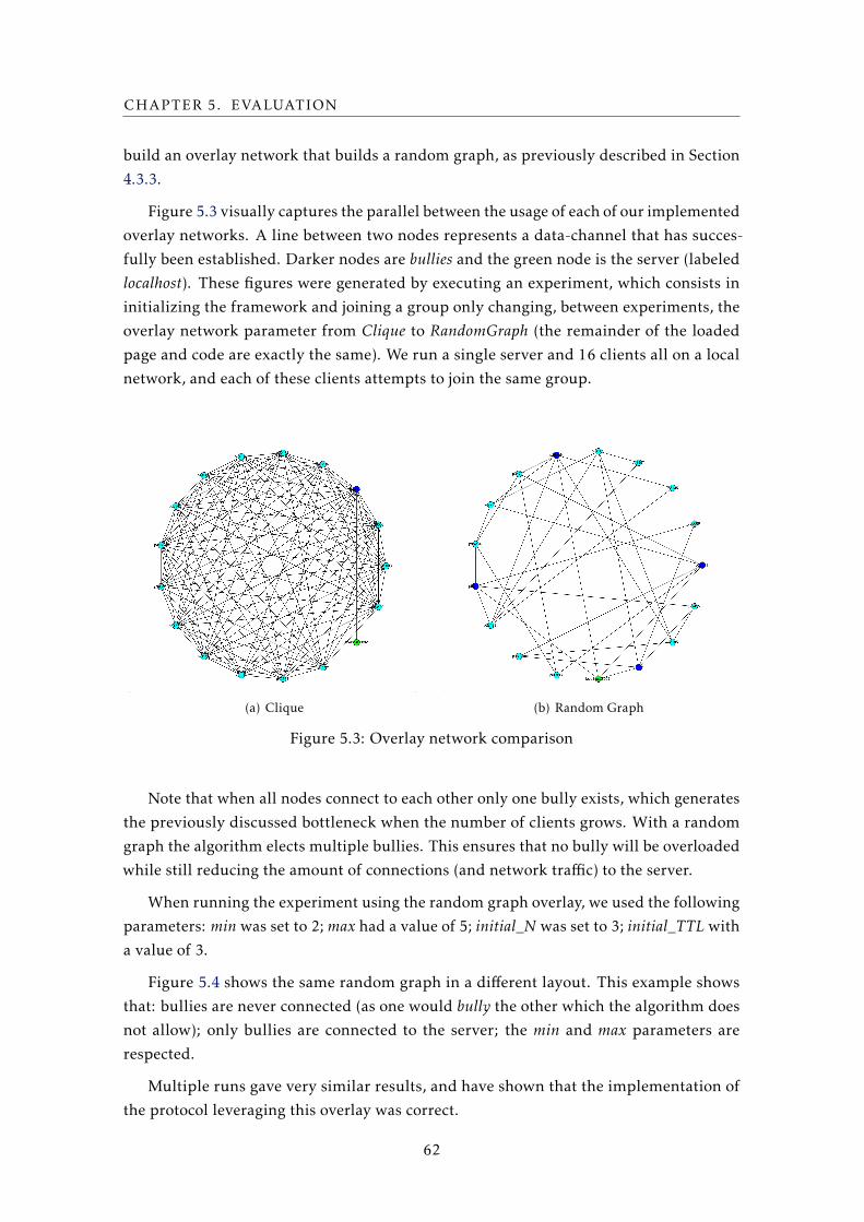
CHAPTER 5. EVALUATION
build an overlay network that builds a random graph, as previously described in Section
4.3.3.
Figure 5.3 visually captures the parallel between the usage of each of our implemented
overlay networks. A line between two nodes represents a data-channel that has succes-
fully been established. Darker nodes are bullies and the green node is the server (labeled
localhost). These figures were generated by executing an experiment, which consists in
initializing the framework and joining a group only changing, between experiments, the
overlay network parameter from Clique to RandomGraph (the remainder of the loaded
page and code are exactly the same). We run a single server and 16 clients all on a local
network, and each of these clients attempts to join the same group.
(a) Clique (b) Random Graph
Figure 5.3: Overlay network comparison
Note that when all nodes connect to each other only one bully exists, which generates
the previously discussed bottleneck when the number of clients grows. With a random
graph the algorithm elects multiple bullies. This ensures that no bully will be overloaded
while still reducing the amount of connections (and network traffic) to the server.
When running the experiment using the random graph overlay, we used the following
parameters: min was set to 2; max had a value of 5; initial_N was set to 3; initial_TTL with
a value of 3.
Figure 5.4 shows the same random graph in a different layout. This example shows
that: bullies are never connected (as one would bully the other which the algorithm does
not allow); only bullies are connected to the server; the min and max parameters are
respected.
Multiple runs gave very similar results, and have shown that the implementation of
the protocol leveraging this overlay was correct.
62
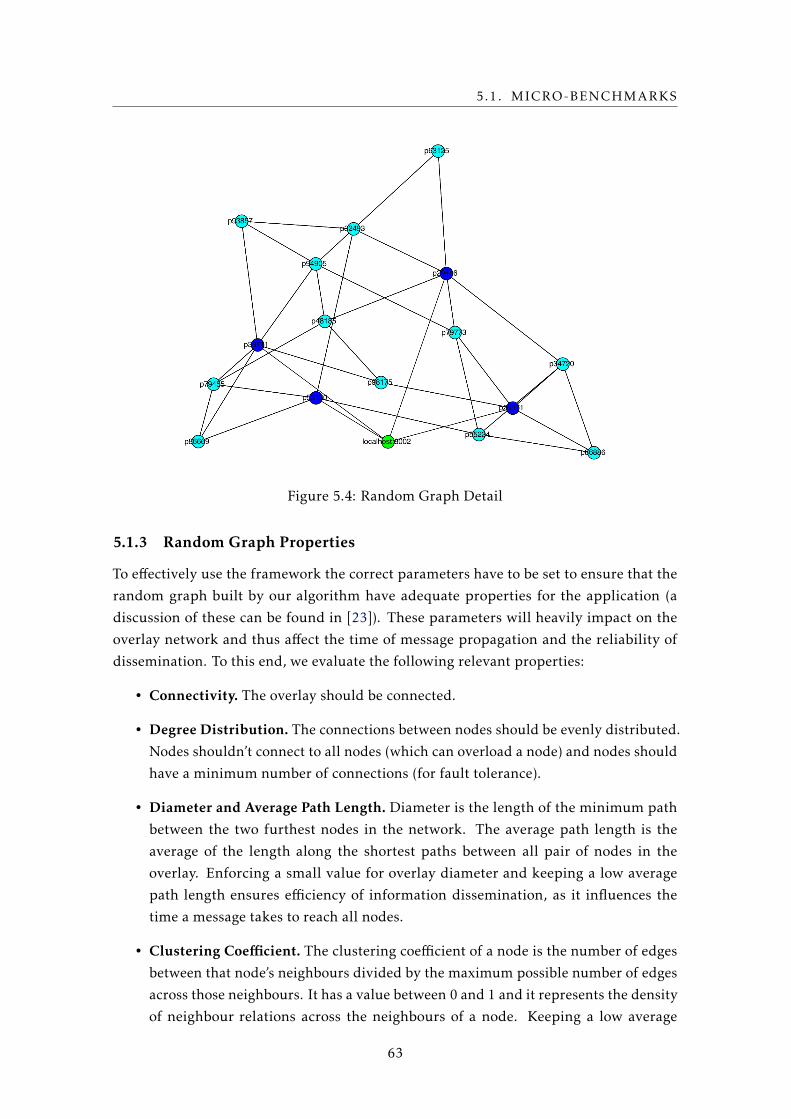
5.1. MICRO-BENCHMARKS
Figure 5.4: Random Graph Detail
5.1.3 Random Graph Properties
To effectively use the framework the correct parameters have to be set to ensure that the
random graph built by our algorithm have adequate properties for the application (a
discussion of these can be found in [23]). These parameters will heavily impact on the
overlay network and thus affect the time of message propagation and the reliability of
dissemination. To this end, we evaluate the following relevant properties:
• Connectivity. The overlay should be connected.
• Degree Distribution. The connections between nodes should be evenly distributed.
Nodes shouldn’t connect to all nodes (which can overload a node) and nodes should
have a minimum number of connections (for fault tolerance).
• Diameter and Average Path Length. Diameter is the length of the minimum path
between the two furthest nodes in the network. The average path length is the
average of the length along the shortest paths between all pair of nodes in the
overlay. Enforcing a small value for overlay diameter and keeping a low average
path length ensures efficiency of information dissemination, as it influences the
time a message takes to reach all nodes.
• Clustering Coefficient. The clustering coefficient of a node is the number of edges
between that node’s neighbours divided by the maximum possible number of edges
across those neighbours. It has a value between 0 and 1 and it represents the density
of neighbour relations across the neighbours of a node. Keeping a low average
63
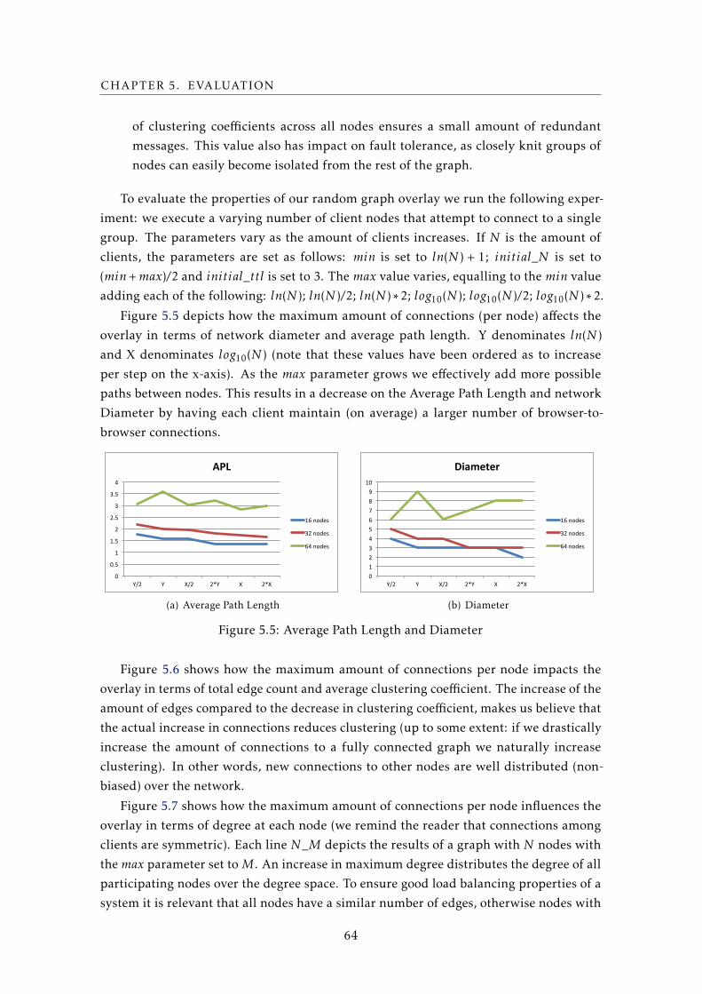
CHAPTER 5. EVALUATION
of clustering coefficients across all nodes ensures a small amount of redundant
messages. This value also has impact on fault tolerance, as closely knit groups of
nodes can easily become isolated from the rest of the graph.
To evaluate the properties of our random graph overlay we run the following exper-
iment: we execute a varying number of client nodes that attempt to connect to a single
group. The parameters vary as the amount of clients increases. If N is the amount of
clients, the parameters are set as follows: min is set to ln(N ) + 1; initial_N is set to
(min+max)/2 and initial_ttl is set to 3. The max value varies, equalling to the min value
adding each of the following: ln(N ); ln(N )/2; ln(N ) ∗ 2; log10(N ); log10(N )/2; log10(N ) ∗ 2.
Figure 5.5 depicts how the maximum amount of connections (per node) affects the
overlay in terms of network diameter and average path length. Y denominates ln(N )
and X denominates log10(N ) (note that these values have been ordered as to increase
per step on the x-axis). As the max parameter grows we effectively add more possible
paths between nodes. This results in a decrease on the Average Path Length and network
Diameter by having each client maintain (on average) a larger number of browser-to-
browser connections.
0"
0.5"
1"
1.5"
2"
2.5"
3"
3.5"
4"
Y/2" Y" X/2" 2*Y" X" 2*X"
APL$
16"nodes"
32"nodes"
64"nodes"
(a) Average Path Length
0"1"2"3"4"5"6"7"8"9"
10"
Y/2" Y" X/2" 2*Y" X" 2*X"
Diameter(
16"nodes"
32"nodes"
64"nodes"
(b) Diameter
Figure 5.5: Average Path Length and Diameter
Figure 5.6 shows how the maximum amount of connections per node impacts the
overlay in terms of total edge count and average clustering coefficient. The increase of the
amount of edges compared to the decrease in clustering coefficient, makes us believe that
the actual increase in connections reduces clustering (up to some extent: if we drastically
increase the amount of connections to a fully connected graph we naturally increase
clustering). In other words, new connections to other nodes are well distributed (non-
biased) over the network.
Figure 5.7 shows how the maximum amount of connections per node influences the
overlay in terms of degree at each node (we remind the reader that connections among
clients are symmetric). Each line N_M depicts the results of a graph with N nodes with
the max parameter set to M. An increase in maximum degree distributes the degree of all
participating nodes over the degree space. To ensure good load balancing properties of a
system it is relevant that all nodes have a similar number of edges, otherwise nodes with
64
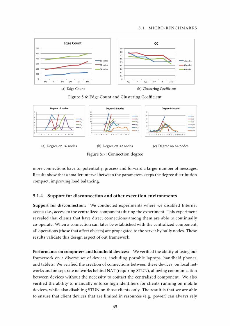
5.1. MICRO-BENCHMARKS
0"
100"
200"
300"
400"
500"
600"
Y/2" Y" X/2" 2*Y" X" 2*X"
Edge%Count%
16"nodes"
32"nodes"
64"nodes"
(a) Edge Count
0"
0.1"
0.2"
0.3"
0.4"
0.5"
0.6"
0.7"
0.8"
0.9"
Y/2" Y" X/2" 2*Y" X" 2*X"
CC"
16"nodes"
32"nodes"
64"nodes"
(b) Clustering Coefficient
Figure 5.6: Edge Count and Clustering Coefficient
0"
1"
2"
3"
4"
5"
6"
7"
8"
1" 2" 3" 4" 5" 6" 7" 8" 9" 10" 11"
Degree%16%nodes%
16_5"
16_6"
16_8"
16_12"
(a) Degree on 16 nodes
0"
2"
4"
6"
8"
10"
12"
14"
16"
18"
1" 2" 3" 4" 5" 6" 7" 8" 9" 10" 11" 12" 13" 14" 15"
Degree%32%nodes%
32_6"
32_7"
32_8"
32_9"
32_10"
32_15"
(b) Degree on 32 nodes
0"
5"
10"
15"
20"
25"
30"
1" 2" 3" 4" 5" 6" 7" 8" 9" 10" 11" 12" 13" 14" 15" 16" 17"
Degree%64%nodes%
64_7"
64_8"
64_9"
64_10"
64_12"
64_18"
(c) Degree on 64 nodes
Figure 5.7: Connection degree
more connections have to, potentially, process and forward a larger number of messages.
Results show that a smaller interval between the parameters keeps the degree distribution
compact, improving load balancing.
5.1.4 Support for disconnection and other execution environments
Support for disconnection: We conducted experiments where we disabled Internet
access (i.e., access to the centralized component) during the experiment. This experiment
revealed that clients that have direct connections among them are able to continually
co-operate. When a connection can later be established with the centralized component,
all operations (those that affect objects) are propagated to the server by bully nodes. These
results validate this design aspect of out framework.
Performance on computers and handheld devices: We verified the ability of using our
framework on a diverse set of devices, including portable laptops, handheld phones,
and tablets. We verified the creation of connections between these devices, on local net-
works and on separate networks behind NAT (requiring STUN), allowing communication
between devices without the necessity to contact the centralized component. We also
verified the ability to manually enforce high identifiers for clients running on mobile
devices, while also disabling STUN on those clients only. The result is that we are able
to ensure that client devices that are limited in resources (e.g. power) can always rely
65
CHAPTER 5. EVALUATION
on other, more powerful nodes, to connect to the browser-to-browser infrastructure, by
having those nodes act as their bullies.
5.2 Case Study: Google Drive Realtime API
In this section we provide a comparison on creating web-applications using the common
client-server communication model and our proposed communication model (browser-to-
browser). To this end we provide a comparative study between the use of the prototype
of our framework and an existing industry solution for building a concrete application,
that serves as a case study. We chose an existing collaborative editing framework as the
baseline, the Drive Realtime API offered by Google.
In contrast to our proposed solution, the interaction between clients using the Google
Drive Realtime API is always mediated by a central component, the server, which decides
how operations are executed and propagated to other clients.
To evaluate our framework we compare the performance of an application designed
to use our framework with the performance obtained of a similar application that relies
on the Google Drive Realtime API. In this evaluation we want to be able to compare both
approaches with respect to the following metrics: i) client-to-client latency observed on
object updates; ii) the amount of data and messages exchanged over time between the
server and the clients in both solutions (and between clients in our solution).
5.2.1 Design
The Google Realtime API provides a service for creating applications where users can
collaborate on maintaining data objects. The Realtime API lets the programmer design
applications that can use maps, lists, and string objects. The propagation of operations
and resolution of conflicting updates is done automatically by the server. Changes are
applied immediately to the, in-memory, local copy of the document. The API will handle
the propagation of changes so that this change can be applied at the server and, eventually,
at other collaborators. Conflicts are automatically resolved, so users never receive any
errors on edit conflicts.
The Realtime data models are eventually consistent. The API guarantees that, if
all collaborators stop editing, eventually all collaborators will see the same data model,
without giving guarantees of a timely delivery, neither on the order of delivery of changes.
The Realtime objects internally use OT, Operation Transformation. Operation Trans-
formation based systems typically adopt a replicated server architecture to ensure good
responsiveness. The documents are replicated at each collaborating site, so that editions
can be immediately performed locally and then be propagated to remote sites. Remote
operations arriving at a site are then transformed before being executed. This transfor-
mation ensures that consistency is maintained across all replicas.
66
5.2. CASE STUDY: GOOGLE DRIVE REALTIME API
5.2.2 Implementation
To compare the systems we create a simplistic application using both frameworks, striving
to maintain these implementatons as close as possible (to ensure that they are compara-
ble). We say simplistic application as we minimize the HTML code and HTML affecting
JavaScript code. In other words, we create methods to modify the objects and to listen
for changes on the objects, but we never present to the interface the state or single up-
dates received. This ensures that the evaluation of both systems will be independent of
interface related effects.
For our evaluation we wrote code which can be divided into two parts: the listener
and the writer methods. The listener (Listing 5.1) can be added to an initialized object
to show the exact time a client receives an update. The writer (Listing 5.2) can be run
on an initialized object to apply writes to an object. The writer can be initialized with
three arguments: a wait time before the experiment begins, an interval between updates,
and a total amount of updates. The write_[gapi|b2b] writes a single character at a random
position on the selected system.
1 var got = 0;
2 function listener() {
3 var date = new Date();
4 console.log(++got + "-" + date.getTime());
5 }
Listing 5.1: "Listener"
1 var TIME_TILL_START, TIME_BETWEEN_SEND , AMOUNT;
2 setTimeout(write, TIME_TILL_START);
3
4 function write() {
5 if (AMOUNT-- > 0) {
6 write_[gapi|b2b](random(0, Selected.size());
7 setTimeout(write, TIME_BETWEEN_SEND);
8 }
9 }
Listing 5.2: "Writer"
5.2.3 Experimental Setup
All reported experiments using our case study were run on Amazon Web Services EC2,
using m3.xlarge machine instances.
In all tests we setup our single server at us-west-1 (California) and we divide the clients
equally over 16 machines, 8 at us-west-2 (Oregon) and 8 at us-east-1 (Virginia). This way
we divide the clients in two equal sized groups (whose size varies in our experiments),
and we allow only for direct communication between clients deployed on the same local
network (i.e., same region). This restriction does not exist in our framework.
67
CHAPTER 5. EVALUATION
In all experiments we use the server in California to serve the static web pages and also
to execute the centralized component of our framework. Clients are executed by loading a
web page into Chromium, the Google Chrome open-source code. We execute the program
by registering all activities to a virtual frame-buffer server, Xvfb, in memory. This allows
us to run an as close as possible to a real world scenario, while keeping graphical related
overheads low, and enabling us to control the experiments.
5.2.4 Latency
In this test we use a single client executing write operations (located in Virginia) and we
measure the time till writes are propagated to other clients. The client that executes write
operations, writes a single character on a List at each of its operations.
We present the latency results between clients on the same local network (i.e., those
that use direct browser-to-browser communication) and clients on seperate networks
(i.e., operations have to be propagated trough a centralized component). To facilitate the
comprehension of these results we show the latency values between the machines used
in this test, measured with the ping tool: i) between Oregon and the server at California:
20 ms; ii) between Virginia and the server at California: 80 ms; iii) between Oregon and
the server of Google: 13 ms; iv) between Virginia and the server of Google: 12 ms; and v)
between Oregon and Virginia: 70 ms.
Note that, to ensure that we measure correct latency results, we use the NT P tool
that executes the network time protocol. As all results have been obtained (as an aver-
age) trough multiple runs on the same configuration, we expect that any discrepancies
produced by NTP are minimized.
Figure 5.8 shows average latencies. The results show that using direct connections
between clients results in a latency which is, as expected, substantially lower than when
communication is mediated through a central component. The Realtime API shows no
significant variation in clients being or not geographically close, which is expected as
all client interactions are mediated by the central component. Our solution, due to the
location of the server and lack of optimizations on the server component, presents higher
latency values when operations are mediated through the central component.
Figures 5.9 (a) and 5.9 (b) present the latency values for, respectively, the 95th per-
centile and the maximum observed value. These results corroborate the previous observa-
tions and furthermore, show that in the case of communication mediated trough a central
component, latency values increase substantially, especially in the worst case scenario.
Also, these results show that latency observed by clients when they use our framework
isn’t significantly affected by the increase in the number of clients. The results show
equally that the system based on the Google Realtime API is very sensitive to the number
of clients, as the latency values rise substantially with the number of clients.
68
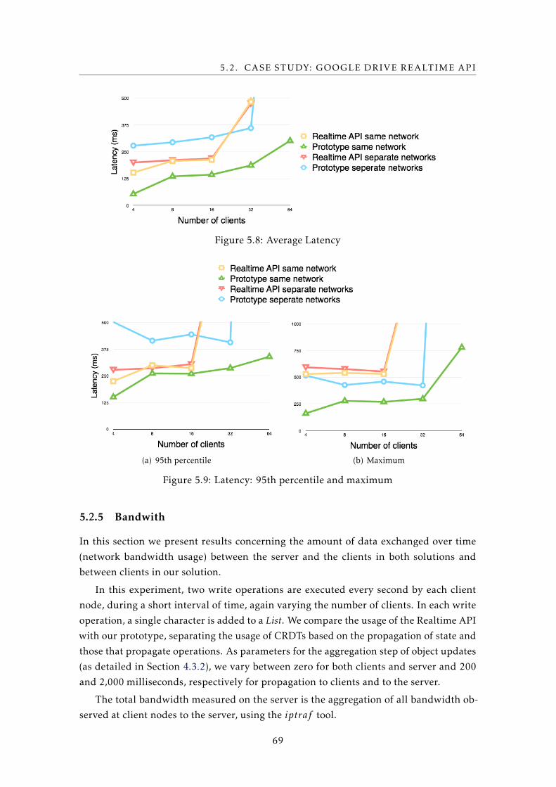
5.2. CASE STUDY: GOOGLE DRIVE REALTIME API
Figure 5.8: Average Latency
(a) 95th percentile (b) Maximum
Figure 5.9: Latency: 95th percentile and maximum
5.2.5 Bandwith
In this section we present results concerning the amount of data exchanged over time
(network bandwidth usage) between the server and the clients in both solutions and
between clients in our solution.
In this experiment, two write operations are executed every second by each client
node, during a short interval of time, again varying the number of clients. In each write
operation, a single character is added to a List. We compare the usage of the Realtime API
with our prototype, separating the usage of CRDTs based on the propagation of state and
those that propagate operations. As parameters for the aggregation step of object updates
(as detailed in Section 4.3.2), we vary between zero for both clients and server and 200
and 2,000 milliseconds, respectively for propagation to clients and to the server.
The total bandwidth measured on the server is the aggregation of all bandwidth ob-
served at client nodes to the server, using the iptraf tool.
69
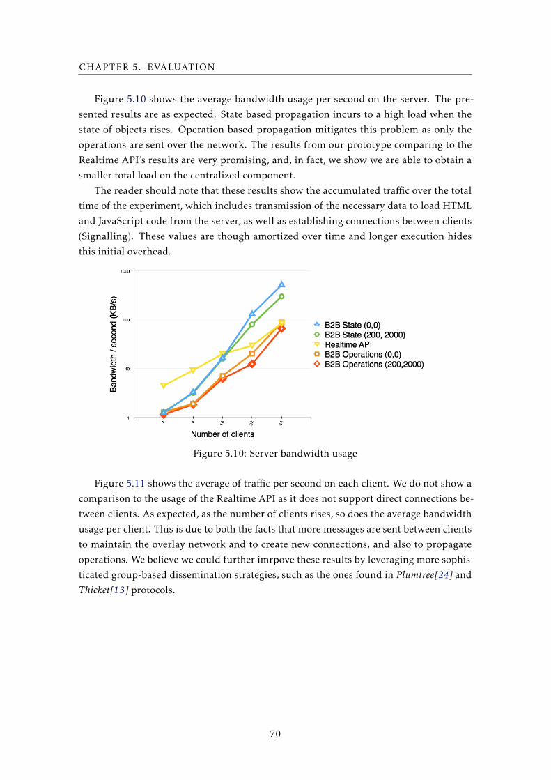
CHAPTER 5. EVALUATION
Figure 5.10 shows the average bandwidth usage per second on the server. The pre-
sented results are as expected. State based propagation incurs to a high load when the
state of objects rises. Operation based propagation mitigates this problem as only the
operations are sent over the network. The results from our prototype comparing to the
Realtime API’s results are very promising, and, in fact, we show we are able to obtain a
smaller total load on the centralized component.
The reader should note that these results show the accumulated traffic over the total
time of the experiment, which includes transmission of the necessary data to load HTML
and JavaScript code from the server, as well as establishing connections between clients
(Signalling). These values are though amortized over time and longer execution hides
this initial overhead.
Figure 5.10: Server bandwidth usage
Figure 5.11 shows the average of traffic per second on each client. We do not show a
comparison to the usage of the Realtime API as it does not support direct connections be-
tween clients. As expected, as the number of clients rises, so does the average bandwidth
usage per client. This is due to both the facts that more messages are sent between clients
to maintain the overlay network and to create new connections, and also to propagate
operations. We believe we could further imrpove these results by leveraging more sophis-
ticated group-based dissemination strategies, such as the ones found in Plumtree[24] and
Thicket[13] protocols.
70
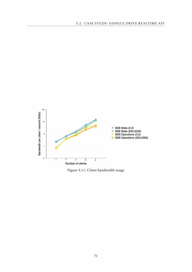
5.2. CASE STUDY: GOOGLE DRIVE REALTIME API
Figure 5.11: Client bandwidth usage
71

Chapter
6Conclusion
Existing web applications, from collaborative editing, social networks, to multi-user
games are fundamentally centered on users and the interaction between them. Even
those applications that run partially or totally on the client machine resort to a model
where interactions between clients are mediated by a centralized component. This cen-
tral component, besides being a contention point on which all interaction between clients
depends, may also introduce latency penalties on those interactions.
In this thesis we proposed an alternative architecture to support web applications
with high user interaction by adding direct and transparent browser-to-browser commu-
nication. This approach has the benefits of improving client-to-client latency, lowering
bandwidth usage on the server (as clients can coordinate to aggregate updates), and
support disconnected operation from the centralized component as clients can directly
exchange information and operate without resorting to the centralized component.
We designed and implemented a prototype of a framework to create web applications
that follows the proposed model, using WebRTC to materialize direct communication
between browsers, and resorting to CRDTs to materialize local object replicas on clients.
Operations can be propagated directly between them, locally updating and reconciling
with other clients the state of these shared and replicated objects. Persistence is achieved
as propagation is eventually done to the centralized component, which is also leveraged
to support clients that operate on non WebRTC compliant browsers. To demonstrate the
benefits of the proposed solution, we implemented a system that exposes an API similar
to the one offered by the Google Drive Realtime.
To evaluate the performance of our implementation we developed micro and macro
benchmarks. The micro-benchmarks evaluate specific parts of the system, namely a
comparison between implemented overlay networks and CRDTs, which validate our pro-
posal. The macro-benchmark was created to compare the performance of our prototype
73
CHAPTER 6. CONCLUSION
to an existing industry solution, in particular the Drive Realtime API offered by Google.
Our results show that we are able to improve on the total server load and on latency
between clients when moving from the traditional client-server communication model
to a browser-to-browser communication model. Our approach can also support client
operation even in periods where the centralized infrastructure is not available.
In summary, the main contributions of the work presented in this thesis are as follows:
• A framework for creating web applications supporting direct browser-to-browser
communication, without the need to install any kind of software or browser plugins.
• The design and implementation of a mechanism to replicate a set of objects in web
applications, combining peer-to-peer interactions and a centralized component.
• A CRDT library that can be used with the replication mechanism for maintaining
the state of different applications, with guarantees of covergence.
• An evaluation of the proposed system and comparison with an existing industry
solution.
Publications
Part of the results in this thesis were published in the following publication:
Enriquecimento de plataformas web colaborativas com comunicação browser-a-
browser Albert Linde, João Leitão e Nuno Preguiça. Actas do sétimo Simpósio de In-
formática, Covilhã, Portugal, September, 2015
6.1 Future Work
In the course of this work, a number of directions for future improvements have been
identified.
The results of our overlay network implementations (presented in Section 5.1.3) meet
our initial requirements but have some limitations. In future work we want to explore
alternative overlay networks. One example is to modify the policy of connection between
clients that are geographically close to each other by giving preference to close clients
while far-away nodes would have fewer connections, if any.
The current library of CRDTs doesn’t provide a realistic solution to all types of ap-
plications. We intend to improve the support for more complex data-types that better
support the creation of different types of applications, as an example, CRDTs that can
guarantee application invariants.
Having clients directly and transparently interacting and exchanging information
among them creates significant challenges from the point of view of security, and in
particular from the perspective of user privacy and data integrity. We aim to explore
74
6.1. FUTURE WORK
fundamental security mechanisms to mitigate attacks that can originate from potential
misbehaving clients.
It would be interesting to integrate persistence with legacy systems, allowing users
running new and old applications to interact. In other words, an existing application
which uses the client-server communication model should be able to run alongside with
clients that use applications that leverage our proposed framework. This would also have
the benefit of allowing to see our systems as an extension to these legacy systems.
75

Bibliography
[1] D. P. Anderson. “Boinc: A system for public-resource computing and storage”.
In: Grid Computing, 2004. Proceedings. Fifth IEEE/ACM International Workshop on.
IEEE. 2004, pp. 4–10.
[2] S. A. Baset and H. Schulzrinne. “An analysis of the skype peer-to-peer internet
telephony protocol”. In: arXiv preprint cs/0412017 (2004).
[3] K. P. Birman, M. Hayden, O. Ozkasap, Z. Xiao, M. Budiu, and Y. Minsky. “Bimodal
multicast”. In: ACM Transactions on Computer Systems (TOCS) 17.2 (1999), pp. 41–
88.
[4] M Bu and E Zhang. PeerJS - Peer-to-Peer Data in the Web Browser. 2013.
[5] B. Cohen. The BitTorrent protocol specification. 2008.
[6] B. F. Cooper, R. Ramakrishnan, U. Srivastava, A. Silberstein, P. Bohannon, H.-A.
Jacobsen, N. Puz, D. Weaver, and R. Yerneni. “PNUTS: Yahoo!’s hosted data serving
platform”. In: Proceedings of the VLDB Endowment 1.2 (2008), pp. 1277–1288.
[7] J. C. Corbett, J. Dean, M. Epstein, A. Fikes, C. Frost, J. J. Furman, S. Ghemawat,
A. Gubarev, C. Heiser, P. Hochschild, et al. “Spanner: Google’s globally distributed
database”. In: ACM Transactions on Computer Systems (TOCS) 31.3 (2013), p. 8.
[8] G. F. Coulouris, J. Dollimore, and T. Kindberg. Distributed systems: concepts anddesign. pearson education, 2005.
[9] G. DeCandia, D. Hastorun, M. Jampani, G. Kakulapati, A. Lakshman, A. Pilchin, S.
Sivasubramanian, P. Vosshall, and W. Vogels. “Dynamo: Amazon’s Highly Available
Key-value Store”. In: SIGOPS Oper. Syst. Rev. 41.6 (Oct. 2007), pp. 205–220. issn:
0163-5980. doi: 10.1145/1323293.1294281. url: http://doi.acm.org/10.
1145/1323293.1294281.
[10] Dropbox. Datastore API. 2015. url: https://www.dropbox.com/developers/
datastore.
[11] EtherpadFoundation. Etherpad. url: http://etherpad.org.
[12] A. J. Feldman, W. P. Zeller, M. J. Freedman, and E. W. Felten. “SPORC: Group
Collaboration using Untrusted Cloud Resources.” In: OSDI. Vol. 10. 2010, pp. 337–
350.
77
BIBLIOGRAPHY
[13] M. Ferreira, J. Leitao, and L. Rodrigues. “Thicket: A protocol for building and
maintaining multiple trees in a p2p overlay”. In: Reliable Distributed Systems, 201029th IEEE Symposium on. IEEE. 2010, pp. 293–302.
[14] A. Ganesh, A.-M. Kermarrec, and L. Massoulié. “SCAMP: Peer-to-peer lightweight
membership service for large-scale group communication”. In: Networked GroupCommunication. Springer, 2001, pp. 44–55.
[15] J. Gentle. ShareJS API. url: https://github.com/share/ShareJS#client-api.
[16] S. Gilbert and N. Lynch. “Brewer’s conjecture and the feasibility of consistent,
available, partition-tolerant web services”. In: ACM SIGACT News 33.2 (2002),
pp. 51–59.
[17] Google. Drive Realtime API. url: https://developers.google.com/google-
apps/realtime/overview.
[18] IETF. STUN. url: https://tools.ietf.org/html/rfc5389.
[19] IETF. TURN. url: https://tools.ietf.org/html/rfc5928.
[20] M. Khan. WebRTC Experiment. url: https://www.webrtc-experiment.com.
[21] R. Klophaus. “Riak core: building distributed applications without shared state”.
In: ACM SIGPLAN Commercial Users of Functional Programming. ACM. 2010, p. 14.
[22] L. Lamport. “Time, clocks, and the ordering of events in a distributed system”. In:
Communications of the ACM 21.7 (1978), pp. 558–565.
[23] J. Leitao. “Topology Management for Unstructured Overlay Networks”. Technical
University of Lisbon, 2012.
[24] J. Leitao, J. Pereira, and L. Rodrigues. “Epidemic broadcast trees”. In: ReliableDistributed Systems, 2007. SRDS 2007. 26th IEEE International Symposium on. IEEE.
2007, pp. 301–310.
[25] J. Leitao, J. Pereira, and L. Rodrigues. “HyParView: A membership protocol for reli-
able gossip-based broadcast”. In: Dependable Systems and Networks, 2007. DSN’07.37th Annual IEEE/IFIP International Conference on. IEEE. 2007, pp. 419–429.
[26] C. Li, D. Porto, A. Clement, J. Gehrke, N. M. Preguiça, and R. Rodrigues. “Making
Geo-Replicated Systems Fast as Possible, Consistent when Necessary.” In: OSDI.2012, pp. 265–278.
[27] D. S. Milojicic, V. Kalogeraki, R. Lukose, K. Nagaraja, J. Pruyne, B. Richard, S.
Rollins, and Z. Xu. Peer-to-peer computing. 2002.
[28] L. Napster. “Napster”. In: URL: http://www. napster. com (2001).
[29] D. A. Nichols, P. Curtis, M. Dixon, and J. Lamping. “High-latency, low-bandwidth
windowing in the Jupiter collaboration system”. In: Proceedings of the 8th annualACM symposium on User interface and software technology. ACM. 1995, pp. 111–120.
78
BIBLIOGRAPHY
[30] G. Oster, P. Urso, P. Molli, and A. Imine. “Proving correctness of transformation
functions in collaborative editing systems”. 2005.
[31] D. S. Parker Jr, G. J. Popek, G. Rudisin, A. Stoughton, B. J. Walker, E. Walton, J. M.
Chow, D. Edwards, S. Kiser, and C. Kline. “Detection of mutual inconsistency
in distributed systems”. In: Software Engineering, IEEE Transactions on 3 (1983),
pp. 240–247.
[32] PeerJS. API Reference. url: http://peerjs.com/docs/.
[33] N. Preguica, J. M. Marques, M. Shapiro, and M. Letia. “A Commutative Replicated
Data Type for Cooperative Editing”. In: Proceedings of the 2009 29th IEEE Interna-tional Conference on Distributed Computing Systems. ICDCS ’09. Washington, DC,
USA: IEEE Computer Society, 2009, pp. 395–403. isbn: 978-0-7695-3659-0. doi:
http://dx.doi.org/10.1109/ICDCS.2009.20. url: http://dx.doi.org/10.
1109/ICDCS.2009.20.
[34] N. Preguiça, M. Zawirski, A. Bieniusa, S. Duarte, V. Balegas, C. Baquero, and M.
Shapiro. “SwiftCloud: Fault-Tolerant Geo-Replication Integrated all the Way to the
Client Machine”. In: Reliable Distributed Systems Workshops (SRDSW), 2014 IEEE33rd International Symposium on. IEEE. 2014, pp. 30–33.
[35] S. Sanfilippo and P. Noordhuis. Redis. 2010.
[36] M. Shapiro, N. Preguiça, C. Baquero, M. Zawirski, et al. “A comprehensive study
of convergent and commutative replicated data types”. 2011.
[37] M. Shapiro, N. Preguiça, C. Baquero, and M. Zawirski. “Conflict-free Replicated
Data Types”. In: Proceedings of the 13th International Conference on Stabilization,Safety, and Security of Distributed Systems. SSS’11. Grenoble, France: Springer-
Verlag, 2011, pp. 386–400. isbn: 978-3-642-24549-7. url: http://dl.acm.org/
citation.cfm?id=2050613.2050642.
[38] G. P. Specification. “version 0.4”. In: available at www9. limewire. com/develop-er/gnutella_protocol_0 4 (2002).
[39] I. Stoica, R. Morris, D. Karger, M. F. Kaashoek, and H. Balakrishnan. “Chord: A
scalable peer-to-peer lookup service for internet applications”. In: ACM SIGCOMMComputer Communication Review 31.4 (2001), pp. 149–160.
[40] S. Voulgaris, D. Gavidia, and M. Van Steen. “Cyclon: Inexpensive membership
management for unstructured p2p overlays”. In: Journal of Network and SystemsManagement 13.2 (2005), pp. 197–217.
[41] W3C. HTML5. url: https://en.wikipedia.org/wiki/HTML5.
[42] W3Cs. WebRTC. url: http://w3c.github.io/webrtc-pc/.
79
BIBLIOGRAPHY
[43] L. Zhang and A. Mislove. “Building Confederated Web-based Services with Priv.Io”.
In: Proceedings of the First ACM Conference on Online Social Networks. COSN ’13.
Boston, Massachusetts, USA: ACM, 2013, pp. 189–200. isbn: 978-1-4503-2084-9.
doi: 10.1145/2512938.2512943. url: http://doi.acm.org/10.1145/2512938.
2512943.
80
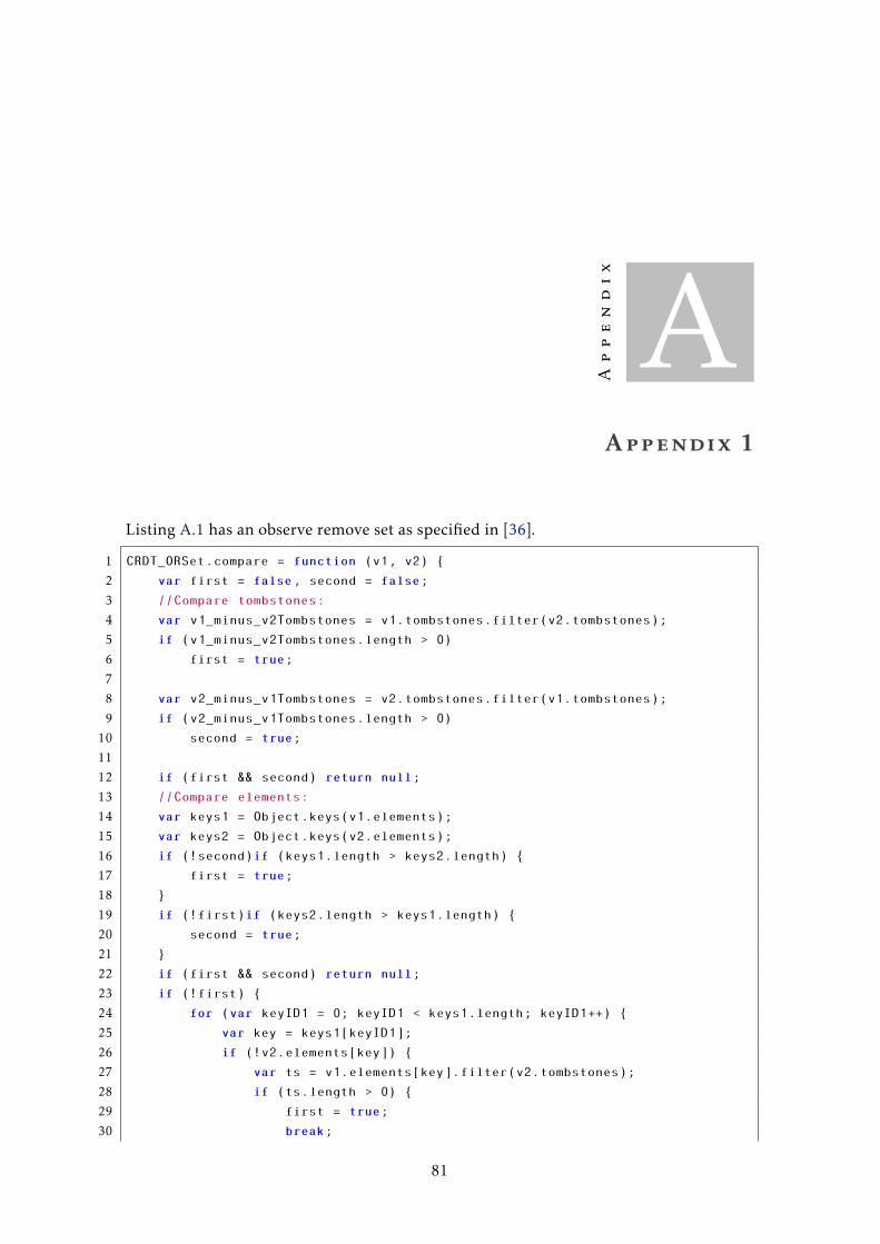
Appendix
AAppendix 1
Listing A.1 has an observe remove set as specified in [36].
1 CRDT_ORSet.compare = function (v1, v2) {
2 var first = false, second = false;
3 //Compare tombstones:
4 var v1_minus_v2Tombstones = v1.tombstones.filter(v2.tombstones);
5 if (v1_minus_v2Tombstones.length > 0)
6 first = true;
7
8 var v2_minus_v1Tombstones = v2.tombstones.filter(v1.tombstones);
9 if (v2_minus_v1Tombstones.length > 0)
10 second = true;
11
12 if (first && second) return null;
13 //Compare elements:
14 var keys1 = Object.keys(v1.elements);
15 var keys2 = Object.keys(v2.elements);
16 if (!second)if (keys1.length > keys2.length) {
17 first = true;
18 }
19 if (!first)if (keys2.length > keys1.length) {
20 second = true;
21 }
22 if (first && second) return null;
23 if (!first) {
24 for (var keyID1 = 0; keyID1 < keys1.length; keyID1++) {
25 var key = keys1[keyID1];
26 if (!v2.elements[key]) {
27 var ts = v1.elements[key].filter(v2.tombstones);
28 if (ts.length > 0) {
29 first = true;
30 break;
81
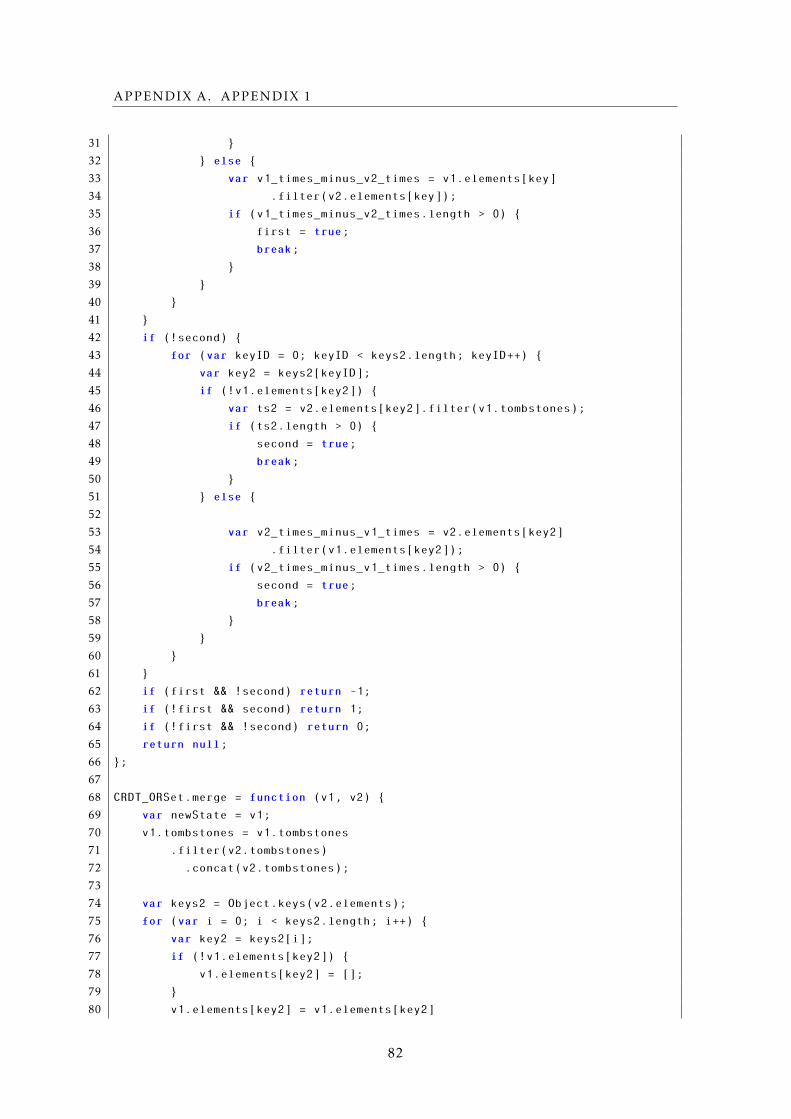
APPENDIX A. APPENDIX 1
31 }
32 } else {
33 var v1_times_minus_v2_times = v1.elements[key]
34 .filter(v2.elements[key]);
35 if (v1_times_minus_v2_times.length > 0) {
36 first = true;
37 break;
38 }
39 }
40 }
41 }
42 if (!second) {
43 for (var keyID = 0; keyID < keys2.length; keyID++) {
44 var key2 = keys2[keyID];
45 if (!v1.elements[key2]) {
46 var ts2 = v2.elements[key2].filter(v1.tombstones);
47 if (ts2.length > 0) {
48 second = true;
49 break;
50 }
51 } else {
52
53 var v2_times_minus_v1_times = v2.elements[key2]
54 .filter(v1.elements[key2]);
55 if (v2_times_minus_v1_times.length > 0) {
56 second = true;
57 break;
58 }
59 }
60 }
61 }
62 if (first && !second) return -1;
63 if (!first && second) return 1;
64 if (!first && !second) return 0;
65 return null;
66 };
67
68 CRDT_ORSet.merge = function (v1, v2) {
69 var newState = v1;
70 v1.tombstones = v1.tombstones
71 .filter(v2.tombstones)
72 .concat(v2.tombstones);
73
74 var keys2 = Object.keys(v2.elements);
75 for (var i = 0; i < keys2.length; i++) {
76 var key2 = keys2[i];
77 if (!v1.elements[key2]) {
78 v1.elements[key2] = [];
79 }
80 v1.elements[key2] = v1.elements[key2]
82
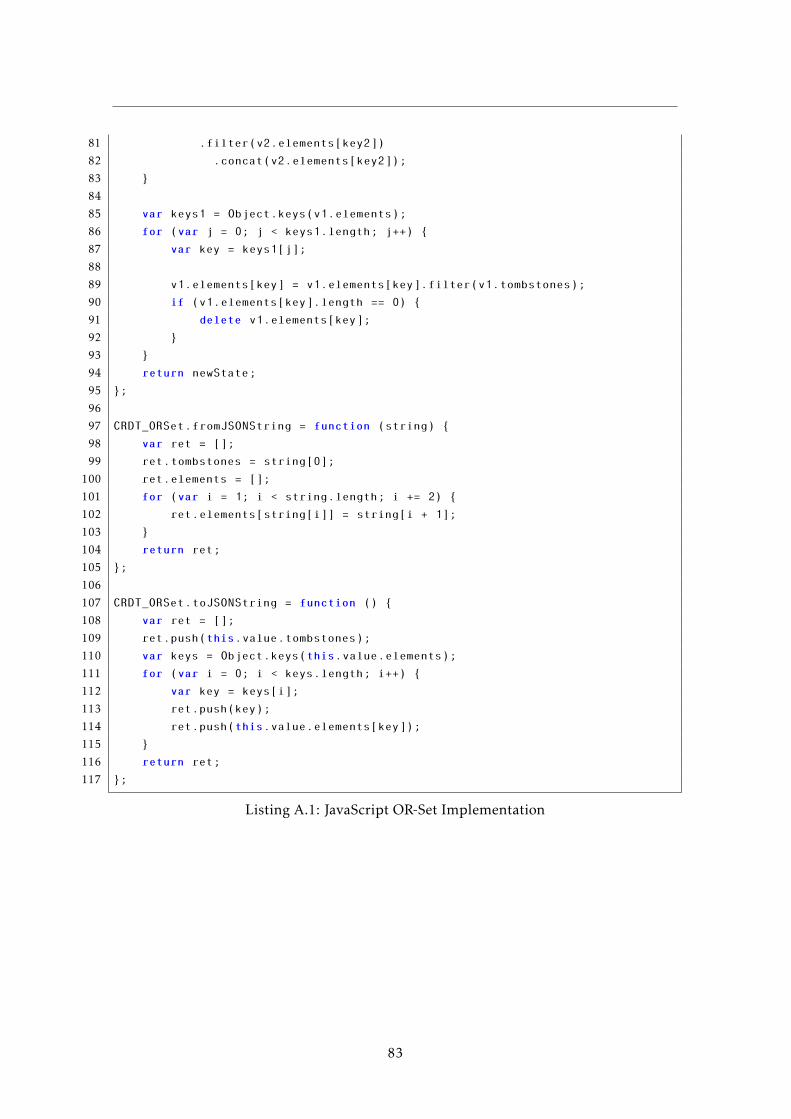
81 .filter(v2.elements[key2])
82 .concat(v2.elements[key2]);
83 }
84
85 var keys1 = Object.keys(v1.elements);
86 for (var j = 0; j < keys1.length; j++) {
87 var key = keys1[j];
88
89 v1.elements[key] = v1.elements[key].filter(v1.tombstones);
90 if (v1.elements[key].length == 0) {
91 delete v1.elements[key];
92 }
93 }
94 return newState;
95 };
96
97 CRDT_ORSet.fromJSONString = function (string) {
98 var ret = [];
99 ret.tombstones = string[0];
100 ret.elements = [];
101 for (var i = 1; i < string.length; i += 2) {
102 ret.elements[string[i]] = string[i + 1];
103 }
104 return ret;
105 };
106
107 CRDT_ORSet.toJSONString = function () {
108 var ret = [];
109 ret.push(this.value.tombstones);
110 var keys = Object.keys(this.value.elements);
111 for (var i = 0; i < keys.length; i++) {
112 var key = keys[i];
113 ret.push(key);
114 ret.push(this.value.elements[key]);
115 }
116 return ret;
117 };
Listing A.1: JavaScript OR-Set Implementation
83