ensc327 communications systems 24: ch. 9: noise in analog … · ensc327 communications systems 24:...
TRANSCRIPT
ENSC327
Communications Systems
24: Ch. 9: Noise in Analog Systems
1
Jie Liang
School of Engineering Science
Simon Fraser University

Chapter 9 Noise in Analog Comm.
� Chap 9 studies noise performance of various analog modulations
� Various SNRs in a system:
� Pre-detection SNR
� Post-detection SNR
� Reference SNR (also known as Channel SNR)
� Figure of Merit
2
� Figure of Merit
� SNR in DSB
� SNR in AM
� SNR in SSB
� SNR in FM
� Main Conclusions:
� DSB and SSB have the same noise performance as the baseband comm system.
� AM has worse noise performance, but has simpler receiver (envelope detector )
� FM has much better noise performance, at the price of the increased bandwidth.
Receiver Model
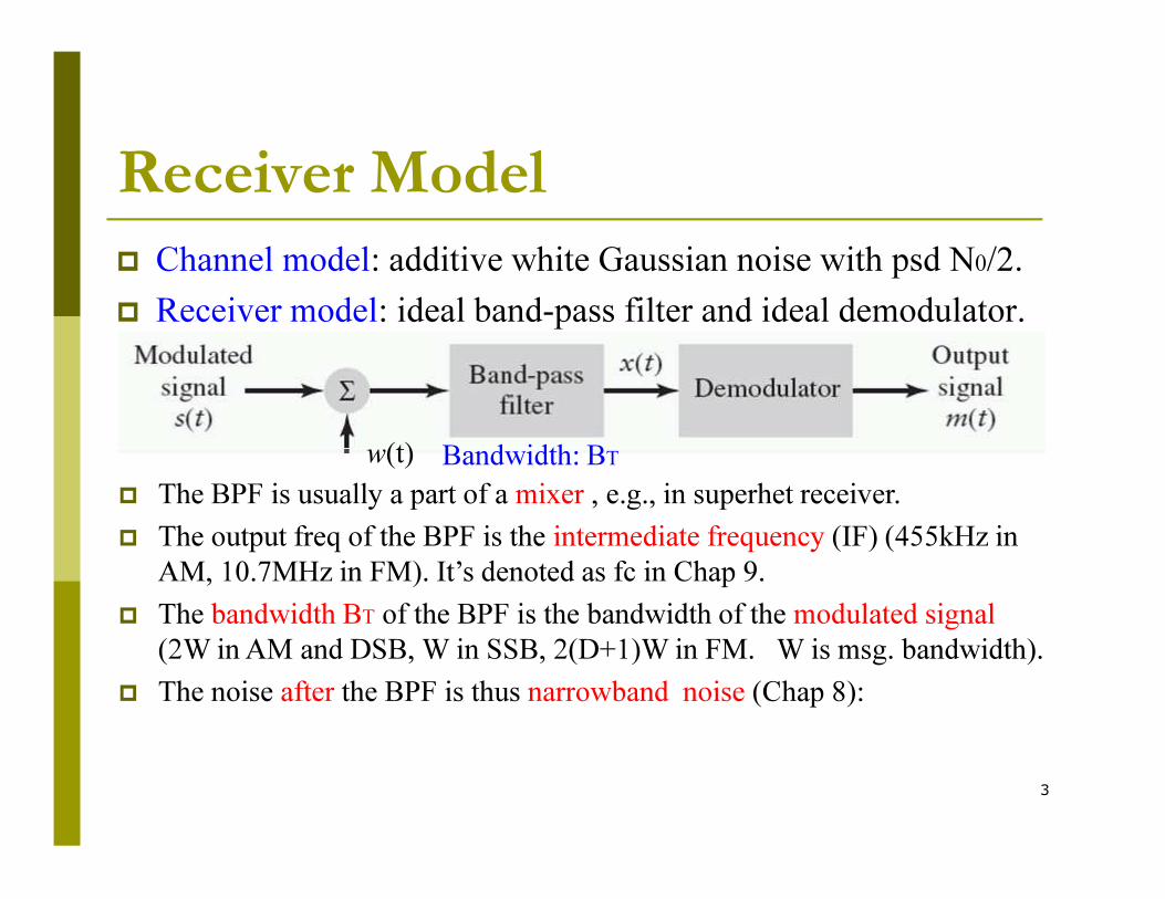
� Channel model: additive white Gaussian noise with psd N0/2.
� Receiver model: ideal band-pass filter and ideal demodulator.
Noise w(t) Bandwidth: BT
3
� The BPF is usually a part of a mixer , e.g., in superhet receiver.
� The output freq of the BPF is the intermediate frequency (IF) (455kHz in
AM, 10.7MHz in FM). It’s denoted as fc in Chap 9.
� The bandwidth BT of the BPF is the bandwidth of the modulated signal
(2W in AM and DSB, W in SSB, 2(D+1)W in FM. W is msg. bandwidth).
� The noise after the BPF is thus narrowband noise (Chap 8):
w(t) Bandwidth: BT

9.3 Band-pass System Structures
� Mixer is usually used to translate the IF frequency to
the RF frequency, or vice versa.
� The IF frequency is denoted as fc in Chap. 9.
fc fc
4
fc fc

Pre-detection SNR
SN(f)
BTN0/2
The bandwidth of x(t):
w(t)
At the input to the demodulator: x(t)=s(t)+n(t),
5
� Pre-detection Signal to Noise Ratio (SNR) at the demodulator
input (after bandpass filter):
The bandwidth of x(t):
The power of the narrowband noise is:
==
noise narrowband theofpower
signal modulated ofpower SNR
pre
Post-detection SNR
w(t)
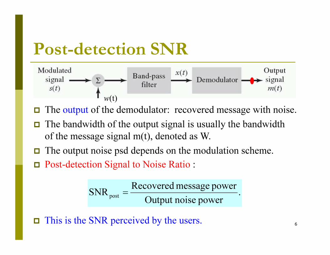
� The output of the demodulator: recovered message with noise.
� The bandwidth of the output signal is usually the bandwidth
6
� Post-detection Signal to Noise Ratio :
.power noiseOutput
power message RecoveredSNR
post=
� This is the SNR perceived by the users.
� The bandwidth of the output signal is usually the bandwidth
of the message signal m(t), denoted as W.
� The output noise psd depends on the modulation scheme.

Reference SNR� To compare noise performances of different modulation systems, we need a
reference baseband transmission model, which transmits the message
directly without any modulation.
� For fair comparison, the transmitted power should be the same as that in a
bandpass modulation system.
� The bandwidth of the LPF at the receiver equals to the message bandwidth
7
==
bandwidth message in thepower noise Average
signal modulated ofpower AverageSNR
ref
� The bandwidth of the LPF at the receiver equals to the message bandwidth
Channel noise
The reference SNR is defined as:

Figure of Merit� The reference SNR can be used to normalize the post-detection
SNR of different methods, so that we can compare them:
SNR Reference
SNRion PostdetectMerit of Figure =
8
� It shows whether a modulation system has better noise
performance than the baseband reference system or not.

Chapter 9 Noise in Analog Comm.
� Various SNRs in a system:
� Pre-detection SNR
� Post-detection SNR
� Reference SNR (also known as Channel SNR)
� Figure of Merit
� SNR in DSB
9
� SNR in DSB
� SNR in AM
� SNR in SSB
� SNR in FM
9.4 SNR in DSB-SC
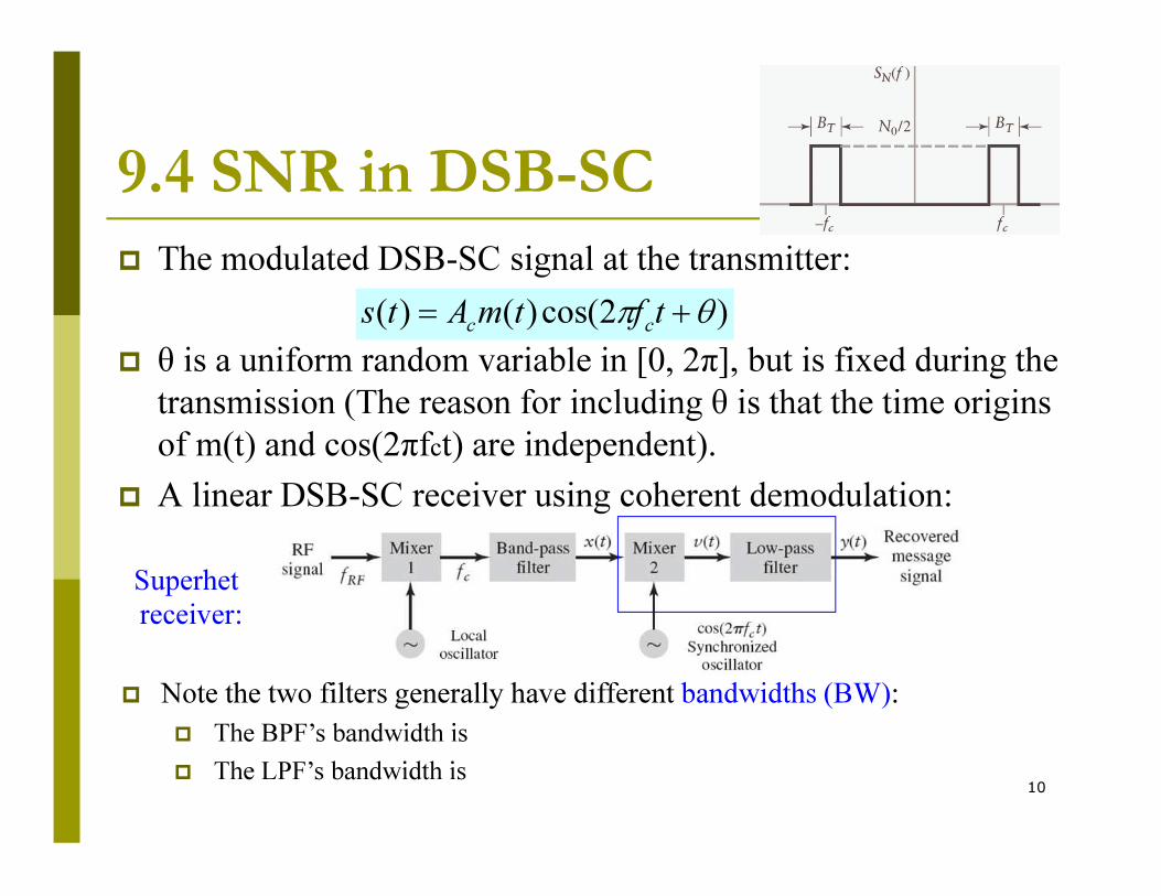
� The modulated DSB-SC signal at the transmitter:
� θ is a uniform random variable in [0, 2π], but is fixed during the
transmission (The reason for including θ is that the time origins
of m(t) and cos(2πfct) are independent).
)2cos()()( θπ += tftmAtscc
10
of m(t) and cos(2πfct) are independent).
� A linear DSB-SC receiver using coherent demodulation:
� Note the two filters generally have different bandwidths (BW):
� The BPF’s bandwidth is
� The LPF’s bandwidth is
Superhet
receiver:

Pre-detection SNR of DSB-SC
� Proof: The pre-detection SNR is defined as:
.2
SNR
0
2
DSB
T
cpre
B�
PA=
� In DSB, BT is 2W, where W is the message bandwidth.
signal modulated ofpower
11
==
noise narrowband theofpower
signal modulated ofpower SNR
pre

Post-detection SNR of DSB-SC� The post-detection SNR is defined as:
.power noiseOutput
power message RecoveredSNR
post=
12
� Assuming θ = 0:
� The signal after the bandpass filter:
� n(t) is narrowband noise with psd N0/2 and bandwidth BT.
).()()( tntstx +=

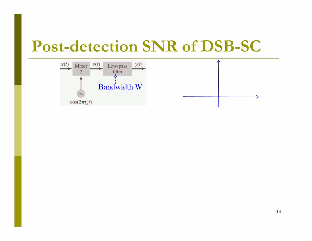
Post-detection SNR of DSB-SC
� After multiplying with the carrier:
Bandwidth W
13
� After low-pass filter with bandwidth W, the output is
� Only in-phase noise appears after LPF!
Post-detection SNR of DSB-SC
Bandwidth W
14
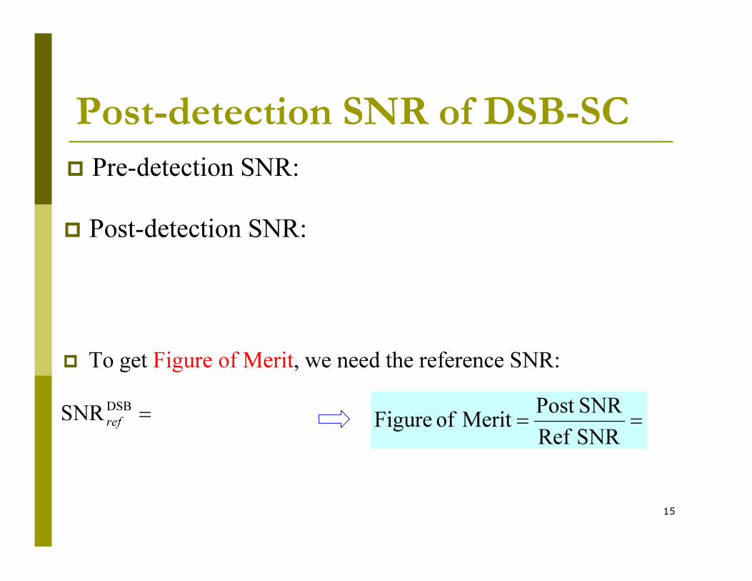
Post-detection SNR of DSB-SC
� Pre-detection SNR:
� Post-detection SNR:
15
� To get Figure of Merit, we need the reference SNR:
=DSB
SNR ref ==
SNR Ref
SNRPost Merit of Figure
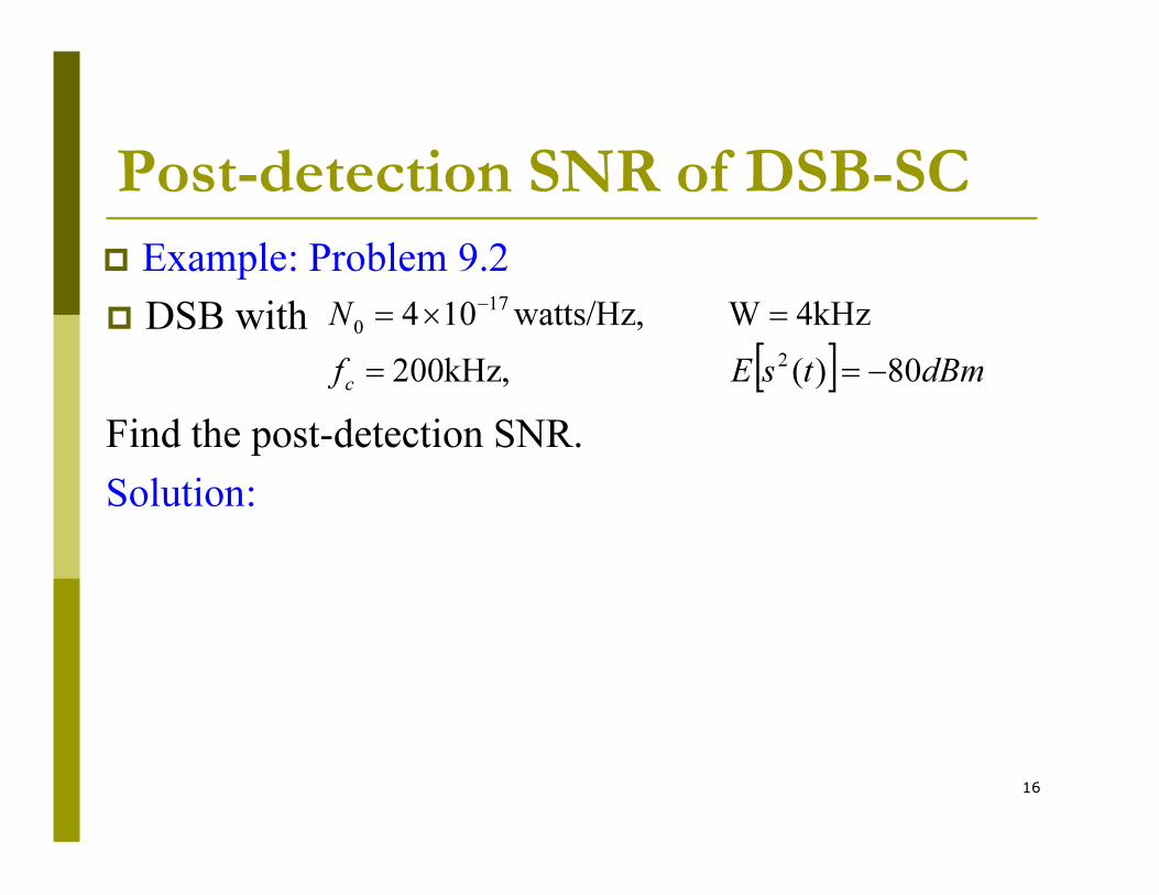
Post-detection SNR of DSB-SC
� Example: Problem 9.2
� DSB with
Find the post-detection SNR.
[ ] dBmtsEf
�
c80)( 200kHz,
4kHzW watts/Hz,104
2
17
0
−==
=×=−
16
Find the post-detection SNR.
Solution:

Chapter 9 Noise in Analog Comm.
� Various SNRs in a system:
� Pre-detection SNR
� Post-detection SNR
� Reference SNR (also known as Channel SNR)
� Figure of Merit
� SNR in DSB
17
� SNR in DSB
� SNR in AM
� SNR in SSB
� SNR in FM
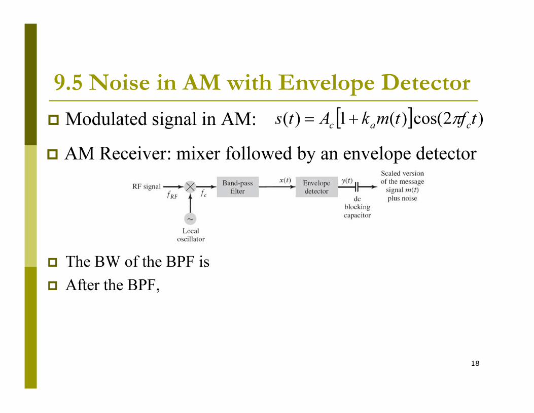
9.5 Noise in AM with Envelope Detector
� Modulated signal in AM: [ ] )2cos()(1)( tftmkAtscacπ+=
� AM Receiver: mixer followed by an envelope detector
18
� The BW of the BPF is
� After the BPF,
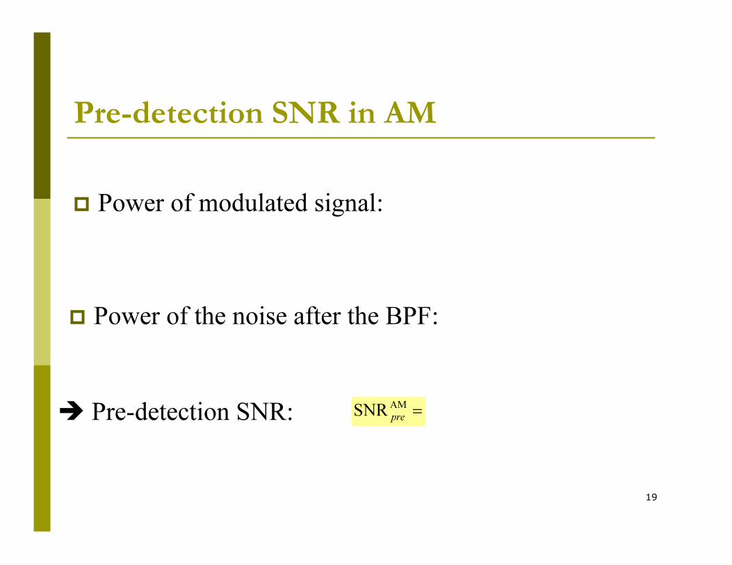
Pre-detection SNR in AM
� Power of modulated signal:
19
� Power of the noise after the BPF:
� Pre-detection SNR: =AM
SNRpre

Post-detection SNR in AM
� The result after BPF can be written as
20
where the envelope is
� When the SNR is high,
� DC term Ac can be removed by a capacitor, so final output is:

Post-detection SNR of AM� The envelope detector output
� The recovered message power is
21
� AM Post-detection SNR:
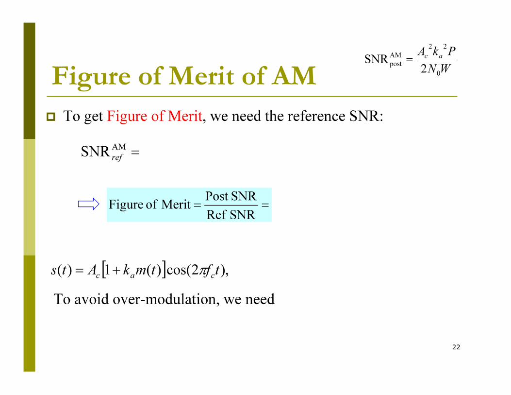
Figure of Merit of AM
� To get Figure of Merit, we need the reference SNR:
=AM
SNR ref
==
SNRPost Merit of Figure
W�
PkAac
0
22
AM
post2
SNR =
22
==
SNR Ref
SNRPost Merit of Figure
[ ] ),2cos()(1)( tftmkAtscacπ+=
To avoid over-modulation, we need
Figure of Merit of AM
� The noise performance of AM is worse than the DSB-SC,
because at least half of the power is spent on the carrier.
==
SNR Ref
SNRPost Merit of Figure AM
23
� The benefit we get is the simpler envelope detector.
Chapter 9 Noise in Analog Comm.
� Various SNRs in a system:
� Pre-detection SNR
� Post-detection SNR
� Reference SNR (also known as Channel SNR)
� Figure of Merit
� SNR in DSB
24
� SNR in DSB
� SNR in AM
� SNR in SSB
� SNR in FM

9.6 Pre-detection SNR in SSB
� SSB signal: ( ) ( )( )tftmtftmA
tscc
c
ππ 2sin)(ˆ2cos)(2
)( m=
� To get the power of SSB signal, we need the following facts:
� 1. m(t) and its Hilbert transform are orthogonal:
( ) .0)(ˆ)( =tmtmE
25
This is because Hilbert transform rotates the signal by 90o.
Example:
� 2. m(t) and its Hilbert transform have the same power.
( ) .0)(ˆ)( =tmtmE
Proof:

Pre-detection SNR in SSB
� Proof:
.4
SNR
0
2
SSB
W�
PAc
pre=Pre-detection SNR of SSB:
26

Post-detection SNR in SSB
� SSB signal:
� SSB signal can be demodulated by coherent method too.
� Using narrowband representation of the noise, the
received signal is (use LSB as example):
( ) ( )( )tftmtftmA
tscc
c
ππ 2sin)(ˆ2cos)(2
)( m=
27
received signal is (use LSB as example):
� After multiplying with the carrier and LPF:

Post-detection SNR in SSB
SN(f)
28
SN(f)
fc-fcf
2/0
�
W
Post-detection SNR in SSB
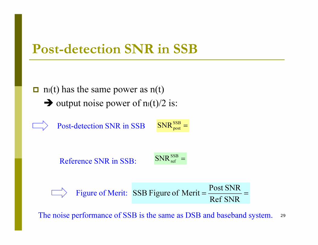
� nI(t) has the same power as n(t)
� output noise power of nI(t)/2 is:
=SSB
SNRPost-detection SNR in SSB
29
=SSB
postSNRPost-detection SNR in SSB
Reference SNR in SSB: =SSB
refSNR
Figure of Merit: ==
SNR Ref
SNRPost Merit of Figure SSB
The noise performance of SSB is the same as DSB and baseband system.

Post-detection SNR of DSB-SC
� Example: Problem 9.5
� SSB with
Find the post-detection SNR.
Solution:
[ ] dBmtsE� 80)( , 4kHz Wwatts/Hz,104 217
0−==×=
−
30
Solution:

Chapter 9 Noise in Analog Comm.
� Various SNRs in a system:
� Pre-detection SNR
� Post-detection SNR
� Reference SNR (also known as Channel SNR)
� Figure of Merit
� SNR in DSB
31
� SNR in DSB
� SNR in AM
� SNR in SSB
� SNR in FM

9.7-9.8 Noise in FM
(Not covered in the final exam)
))(22cos()(0∫+=
t
fcc dmktfAts ττππ
32
� It can be shown that the figure of merit of FM modulation is
.4
3merit of Figure
2
=
W
BT
� Performance depends on the bandwidth of the modulated signal!
This is different from DSB, AM, and SSB.
� An increase in the bandwidth BT can significantly improve the
noise performance of FM system.

Chapter 9 Noise in Analog Comm.
� Main Conclusions:
� DSB and SSB have the same noise performance as the
baseband comm system.
� AM has worse noise performance, but has simpler receiver
(envelope detector )
33
(envelope detector )
� FM has much better noise performance, at the price of the
increased bandwidth.