~entered a 718 :»!:),-:;>/, alamos i '-',.?7 · ,. national laboratory alamos national...
TRANSCRIPT

A ~Los Alamos
NATIONAL LABORATORY --- EST.1943 ---
Environmental Programs P.O. Box 1663, MS M991 Los Alamos, New Mexico 87545 (505) 606-2337/FAX (505) 665-1812
John Kieling, Bureau Chief Hazardous Waste Bureau
/ I ·.
t (::·
'·
New Mexico Environment Department 2905 Rodeo Park Drive East, Building 1 Santa Fe, NM 87505-6303
718 :»!:),-:;>/, . . '-',.?7
"· MAR 2013
,. ·t-l o' ~ (J1 0)
-.....: q,
~ENTERED
National Nuclear Security Administration Los Alamos Field Office, MS A316 Environmental Projects Office Los Alamos, New Mexico 87544 (505) 667-4255/FAX (505) 606-2132
Date:MAR 2 8 2013 Refer To: EP2013-0007
Subject: Submittal of the Drilling Work Plan for Well CdV-9-l(i)
Dear Mr. Kieling:
Enclosed please find two hard copies with electronic files of the Drilling Work Plan for Well CdV-9-1(i). This document was prepared in response to the New Mexico Environment Department (NMED) Approval with Modifications Technical Area 16 Network Evaluation and Recommendations, dated June 20, 2012.
If you have any questions, please contact John McCann at (505) 665-1091 ([email protected]) or Woody Woodworth at (505) 665-5820 ([email protected]).
Sincerely,
Jeff Mousseau, Associate Director Environmental Programs Los Alamos National Laboratory
Sincerely,
~~h~ Peter Maggiore, Assistant Manager Environmental Projects Office Los Alamos Field Office
An Equal Opportunity Employer I Operated by Los Alamos National Security, LLC fc National Nuclear Security Administration of the U.S. Department of Energy
111111111111 ~~~~ffllllllllllllll

John Kieling 2 EP2013-0007
JM/PM/CD/JM:vt
Enclosures: Two hard copies with electronic files - Drilling Work Plan for Well CdV -9-1 (i) (LA-UR-13-20779)
Cy: (w/enc.) Woody Woodworth, DOE-NA-00-LA, MS A316 John McCann, EP-CAP, MS M992 Public Reading Room (hard copy) RPF (electronic copy)
Cy: (Letter and CD and/or DVD) Laurie King, EPA Region 6, Dallas, TX Steven Rydeen, San Ildefonso Pueblo Joe Chavarria, Santa Clara Pueblo Steve Yanicak, NMED-DOE-OB, MS M894 Mark Everett (w/ MS Word files on CD) Wendy Staples, EP-BPS, MS M992
Cy: (w/o enc.) Tom Skibitski, NMED-Resource Protection (date-stamped letter emailed) lasomailbox@ nnsa.doe.gov (date-stamped letter emailed) Annette Russell, DOE-NA-00-LA (date-stamped letter emailed) David Rhodes, DOE-NA-00-LA (date-stamped letter emailed) Craig Douglass, EP-CAP (date-stamped letter emailed) Jeff Mousseau, ADEP (date-stamped letter emailed)
Primary Purpose
Conceptual Model
Drilling Approach
LA-UR-13-20779 EP2013-0007
Drilling Work Plan for Well CdV-9-1(i)
Drilling Work Plan for Well CdV-9-1(i)
Well CdV-9-1(i) is being installed to satisfy a recommendation made in the Technical Area 16 (TA-16) well network evaluation and recommendations document and accepted in the New Mexico Environment Department (NMED) approval with modifications letter dated June 20, 2012 (LANL 2012, 213573; NMED 2012, 520747). The network evaluation document recommended the installation of a deep-perched groundwater monitoring well north of Canon de Valle to determine the northern extent of high explosives- (HE-) contaminated groundwater in this zone. In the approval with modifications letter, NMED directed Los Alamos National Laboratory (LANL or the Laboratory) to install two single-screen wells in the upper and lower deep-perched zones if adequate groundwater is present. The Laboratory proposes to initially install well CdV-9-1(i) northeast of well CdV-16-1(i) (Figure 1). The well will be installed in a target zone based on information obtained during drilling of the well and from drilling of regional aquifer well R-47. A recommendation on the need for a second well will be submitted to NMED within 120 d after completion of the first well. A final location for well CdV-9-1 (i) will be discussed with NMED based on data collected during installation of regional aquifer well R-47 and the direct current-resistivity survey proposed for Canon de Valle; both will provide important information relevant to the spatial extent of the perched zone north of Canon de Valle. The primary purpose of CdV-9-1 (i) is to monitor contaminants associated with Consolidated Unit 16-021 (c)-99 (also known as the 260 Outfall). Water-level data from this location will also constrain the extent of the perched-intermediate zone of saturation and groundwater flow directions in this area.
The depth to the top of the perched intermediate zone of saturation at CdV-9-1 (i) is expected to be approximately 795 ft. The target depth for the borehole is 1220 ft, about 30 ft below the projected bottom of the lower screen at CdV-16-4ip and about 75 ft above the expected elevation of the regional aquifer. The depth and occurrence of perched and regional groundwater is uncertain, and the target depth may be adjusted once the water depth and producing intervals are evaluated at this location.
Figure 2 shows the predicted geology, expected groundwater-producing intervals, and proposed well design for CdV-9-1(i). The well is tentatively designed with a single well screen to be placed near the depth of CdV-16-4ip screen 2 (projected to be 1156-1187 ft) in Puye Formation deposits. Alternatively, the uppermost producing interval corresponding to the highest RDX (hexahydro-1 ,3,5-trinitro-1 ,3,5-triazine) screening results observed during drilling may be selected for screen placement. Final selection of well screen length and position will be based on data obtained during drilling, including information from lithologic logs of cuttings, water-level measurements, RDX screening results, video logs, geophysical logs, and drill crew observations.
A final well design will be based on hydrogeological conditions encountered during drilling, and a revised well design document will be submitted to NMED for approval before well construction begins.
The conceptual model for the 260 Outfall area is of a line-source recharge to the deep-perched saturated zone symmetric along the east-west trace of Canon de Valle downstream from the outfall. The potential exists for zones of contaminated perched-intermediate groundwater similar to those south of Canon de Valle to be present north of the canyon. Installation of well CdV-9-1 (i) will further refine the conceptual model.
Drilling will be conducted with methods selected to optimize the potential of completing the well without using drilling additives in, or immediately above, the target zone of saturation. A combination of open-hole and casing-advance methods will be employed. Each interval of open hole or casing advance will be optimized to meet well objectives. Casing will be advanced through the deep-perched saturated interval to evaluate relative groundwater flow and to collect RDX screening samples. Estimates of groundwater production will be made during the advancement of each 20-ft section of drill casing. A screening sample will be air-lifted at startup after each new joint connection.
Apri/2013

Drilling Work Plan for Well CdV-9-1(i)
Potential Drilling Fluids, Composition, and Use
Hydrogeologic and Geochemical Objectives
Potential Groundwater Occurrence and Detection
Core Sampling
Perched Groundwater Screening Sampling
Perched Groundwater Characterization Sampling
April2013
Fluids and additives that may be used to facilitate drilling will be consistent with those previously used in the drilling program at the Laboratory and already characterized geochemically. Fluids and additives previously authorized for use by NMED include
• potable municipal water supply to aid in the delivery of other drilling additives and cooling the drill bit;
• QUIK-FOAM, a blend of alcohol ethoxy sulfates, used as a foaming agent; and
• AQF-2, an anionic surfactant, used as a foaming agent.
Complete records will be maintained detailing the type, amount, and volume of drilling fluid used, the depth at which drilling fluid is added to the borehole, the amount in storage in the borehole, and the recovery volume of drilling fluid. No drilling fluids, except potable municipal water, will be used within 1 00 ft of the perched-intermediate zone of saturation. If the target zone cannot be reached without the addition of drilling fluids, the situation will be discussed with NMED. No chemicals, other than those listed above, will be added without NMED's approval.
• The primary objective is to characterize the deep-perched zone of saturation and to . monitor groundwater quality downgradient of the 260 Outfall at TA-16.
• A secondary objective is to establish water levels and gradients in the deep-perched saturated zone in this area.
Potential Perched Water: Based on drilling observations at wells in the area, perched water is expected at this location. The predicted depths of groundwater are 90-113 ft and 795-1220 ft below ground surface (bgs) (total drilled depth). The depth and length of saturated sections within the 795-1220-ft interval are unknown.
Regional: Drilling will terminate at 1220 ft bgs, approximately 75ft above regional saturation.
Methods to detect perched groundwater may include driller's observations, water-level measurements, borehole video, borehole geophysics, and monitoring for pressure responses in nearby wells.
No core collection is planned.
A groundwater screening sample will be air-lifted during drilling from the first deepintermediate zone of saturation. The screening sample will be analyzed for cations/metals (dissolved and total) and anions (dissolved) by the Earth and Environmental Sciences (EES) Division's Geochemistry and Geomaterials Research Laboratory (GGRL) and for HE and tritium by off-site laboratories. Additionally, RDX screening samples will be collected every 20 ft while drilling through the deep-perched interval. These samples will be submitted to the EES Division's GGRL for RDX analysis with a minimum detection limit of 2 ppb.
Groundwater samples will be collected from the completed well between 1 0 d and 60 d after well development in accordance with the Compliance Order on Consent. These samples will be analyzed for the full suite of TA-16-related constituents, including tritium; metals/cations; general inorganic chemicals; volatile organic compounds; semivolatile organic compounds; HE compounds, including RDX and related degradation products; as well as stable isotopes.
Subsequent groundwater samples will be collected in accordance with the requirements of the Interim Facility-Wide Groundwater Monitoring Plan (the Interim Plan).
2 LA-UR-13-20779 EP2013-0007

Geophysical Testing
Well Completion Design
Drilling Work Plan for Well CdV-9-1(i)
The Laboratory's borehole video camera, natural gamma, and induction tools will be used in the open borehole if conditions allow.
A full suite of geophysical logs will be run, if required, for proper placement of the screen. The logs will be collected by Schlumberger, Inc., and for open-hole conditions, will include accelerator porosity sonde (neutron porosity}, array induction, combined magnetic resonance, natural and spectral gamma, and formation microimager logs. In cased portions of the borehole, neutron porosity, triple lithodensity, elemental capture, natural gamma, and spectral gamma logs will be collected. These logs will be used to characterize the hydraulic properties of saturated rocks in the regional aquifer.
The geophysical logs also will be used to select the well screen depths. The suite and timing of geophysical logging will depend on borehole conditions.
Figure 2 shows the conceptual well design and predicted geology for well CdV-9-1(i).
Well Development The well may be developed by both mechanical and chemical means. Mechanical means include swabbing, bailing, and pumping. Chemical means include the use of additives to remove clays and/or chlorination to kill bacteria introduced during well completion.
Hydraulic Testing
InvestigationDerived Waste Management
LA-UR-13-20779 EP2013-0007
• After initial swabbing and bailing, a submersible pump will be used to complete the development process.
• Water-quality parameters will be measured in a flow-through cell. The parameters to be monitored are pH, specific conductance, dissolved oxygen, temperature, turbidity, oxidation-reduction potential, and total organic carbon (TOC).
• If the Laboratory is unable to bring the water-quality parameters to within the limits specified below, the use of chemical well development may be discussed with NMED. No chemicals will be added without NMED's approval.
Chemical means that may be used include sodium acid pyrophosphate and AQUACLEAR PFD to remove clays and/or chlorination.
Well development will be considered complete when target water-quality parameters are met and a volume of water equivalent to that which was introduced into the aquifer during drilling and construction is removed. The target water-quality parameters are turbidity <5 nephelometric turbidity units, TOC <2 ppm, and other parameters stable.
Hydraulic testing will be considered if a sufficiently robust zone within the aquifer is encountered. The most likely test will be a 24-h constant-rate pumping test.
Investigation-derived waste (IDW) will be managed in accordance with the requirements in P-409, Waste Management, and EP-DIR-SOP-10021, Characterization and Management of Environmental Programs Waste, available at http://www.lanl.gov/communityenvironment/environmental-stewardship/plans-procedures.php. This standard operating procedure incorporates the requirements of applicable U.S. Environmental Protection Agency and NMED regulations, U.S. Department of Energy orders, and Laboratory requirements. The primary waste streams include drill cuttings, drilling water, development water, purge water, decontamination water, and contact waste.
3 Apri/2013

Drilling Work Plan for Well CdV-9-1(i)
Investigation- Drill cuttings will be managed in accordance with the NMED-approved Notice of Intent (NOI) Derived Waste Decision Tree for Land Application of IDW Solids from Construction of Wells and Boreholes Management (November· 2007). Drilling, purge, and development waters will be managed in accordance (continued) with the NMED-approved NOI Decision Tree for Drilling, Development, Rehabilitation, and
Sampling Purge Water (November 2006). Initially, drill cuttings and drilling water will be stored in lined pits. The cuttings may or may not contain residue of drilling/well completion additives (e.g., drilling foam and bentonite clay). The contents of the pits will be characterized with direct sampling following completion of drilling activities, and waste determinations will be made from validated data. If validated analytical data show these wastes cannot be land-applied, they will be removed from the pit, containerized, and placed in accumulation areas appropriate to the type of waste. Cuttings, drilling water, development water, and purge water that cannot be land-applied and are designated as hazardous waste will be sent to an authorized treatment, storage, or disposal facility within 90 d of containerization. Development water, purge water, and decontamination water will be containerized separately at their point of generation, placed in an accumulation area appropriate to the type of waste, and directly sampled. Contact waste will be containerized at the point of generation, placed in an appropriate accumulation area, and characterized using acceptable knowledge of the media with which it came in contact.
Schedule Well CdV-9-1 (i) is proposed for completion by October 31, 2013. This date assumes that additional funding will be available beginning April 1, 2013, to support the proposed completion date.
Monitoring conducted after CdV-9-1 (i) is installed will be implemented under the Interim Plan and will support investigations and corrective actions at TA-16.
REFERENCES
The following Jist includes all documents cited in this plan. Parenthetical information following each reference provides the author(s), publication date, and ER /D. This information is also included in text citations. ER IDs are assigned by the Environmental Programs Directorate's Records Processing Facility (RPF) and are used to locate the document at the RPF and, where applicable, in the master reference set.
Copies of the master reference set are maintained at the NMED Hazardous Waste Bureau and the Directorate. The set was developed to ensure that the administrative authority has all material needed to review this document, and it is updated with evel)l document submitted to the administrative authority. Documents previously submitted to the administrative authority are not included.
LANL (Los Alamos National Laboratory), March 2012. "Technical Area 16 Well Network Evaluation and Recommendations," Los Alamos National Laboratory document LA-UR-12-1082, Los Alamos, New Mexico. (LANL 2012, 213573)
NMED (New Mexico Environment Department), June 20, 2012. "Approval with Modifications, Technical Area 16 Well Network Evaluation and Recommendations," New Mexico Environment Department letter to P. Maggiore (DOE-LASO) and M.J. Graham (LANL) from J.E. Kieling (NMED-HWB), Santa Fe, New Mexico. (NMED 2012, 520747)
Apri/2013 4 LA-UR-13-20779 EP2013-0007
1616000 - -0 0 0 0 d
R-18~ lJ' a 0 o o Q
...
\
r .. , .. :.b ;,~
/
1 ~.. ••
~---TA~9 .. . . ··':·--·-·.
0
Canon de _valle · :·:
-;, ~:: I c J "-. . ..
'\._ •• "R~26 •
I Zia e Shops
~
Area A Canyon
. ...._
0
0
30s Line ......,, Ponds
.·.
~
Proposed location I 'f. for CdV-9-1(1) MDAP
.-.J ·~
b
.,
.... R-63
..... CdV-16-2(i) ~ ':\
~ ~~~··· R-25c ·i CaV-16:4ip •
R-25b R-25 ~ .
~ ~~ ~ •::
i
5-Site Canyon
~ 0
. Fish ladder Canyon
~ ··~ ··~ .. -~ •• - •• """ •• ,.,... •• -Water e anyon-" • • _,.... •• ··~
1610000
Hgure
LA-UR-13-20779 EP2013-0007
1812000
roposed locat1on of well CdV-9-1 (i)
1614000 1616000 1618000
TA-14
...... " \ .
_j,R-47.i •. ' ~ :.· ,''
\-.. ,,'<':: ----.-- · ...
' ·\·. -·-
r-
Drilling Work Plan for Well CdV-9-1 (i)
1622000
Proposed drilling location
Peter Seep
Well
Infiltration area outline
Infiltration area
SWMU (site outline)
TA boundary
Structure 16-260, Consolidated Unit 16-021(c)-99
LANL Structure
Watershed boundary
Drainage
Paved road
Unpaved road
Contour, 100-ft interval
New Mexico State Plane Coordinate System Central Zone (3002) North American Datum, 1983 (NAD 83) National Geodetic Vertical Datum of 1929 (NGVD 1929, Hypsography 100 and 20ft contours)
US SurveyFt
GIS: Dave Frank, [email protected], 665-8182 Date: 02-January-2013 Revision: 0.0 Revised: Map Number: 11-0057-05
DISCLAIMER: This map was created for work processes associated with EP-ET-ER division. All other uses for this map should be confirmed with LANL staff.
N
o 1.000 A 2.000
Feet
1622000
5
·t~
I
Apri/2013

Drilling Work Plan for Well CdV-9-1(i)
Elevation (ft)
7500
7400
7300
7200
7100
7000
6900
6800
6700
6600
6500
6400
6300
Depth (ft)
0
100
200
300
400
500
600
700
800
900
1000
1100
1200
CdV-9-1(i) Elevation 7510 ft
Qbt4 - ss
T 90 Qbt 3t 1---------~.. - - -f-'-__E»ossib_!e ~ ZOil!...1-ta-
Qbt3
Tshirege Member - 208-ofthe
Bandelier Tuff Qbt 2
Qbt 1v-=~f=
Qbt 1g
F=====/~=========!~~= Tsankawi Pumice Bed
Cerro Toledo
Otowi Member of the Bandelier Tuff\.
1 -r-r-? "-1---"1.---1 T . 795 -r-?'..~ l======;:z:=:::::U!=
Guaje Pumice Bed / .
Note: Saturaled Intervals .. possible throughout the 795 to 1220 ft zone.
Puye Formation
TD 1220
Conceptual Well Design
/__LI Cement surface seal
Annular seal
Secondary filter pack
Primary filter pack
Annular seal
Note: Screen placement will be determined based on depths of saturation observed during drilling.
Figure 2
Apri/2013
Predicted geology and proposed well design for well CdV-9-1(i)
6 LA-UR-13-20779 EP2013-0007
Drilling Work Plan for Well CdV-9-1(i)
LA-UR-13-20779 1 April 2013 EP2013-0007
Drilling Work Plan for Well CdV-9-1(i)
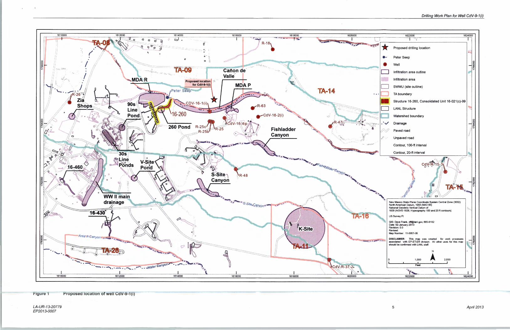
Primary Purpose Well CdV-9-1(i) is being installed to satisfy a recommendation made in the Technical Area 16 (TA-16) well network evaluation and recommendations document and accepted in the New Mexico Environment Department (NMED) approval with modifications letter dated June 20, 2012 (LANL 2012, 213573; NMED 2012, 520747). The network evaluation document recommended the installation of a deep-perched groundwater monitoring well north of Cañon de Valle to determine the northern extent of high explosives- (HE-) contaminated groundwater in this zone. In the approval with modifications letter, NMED directed Los Alamos National Laboratory (LANL or the Laboratory) to install two single-screen wells in the upper and lower deep-perched zones if adequate groundwater is present. The Laboratory proposes to initially install well CdV-9-1(i) northeast of well CdV-16-1(i) (Figure 1). The well will be installed in a target zone based on information obtained during drilling of the well and from drilling of regional aquifer well R-47. A recommendation on the need for a second well will be submitted to NMED within 120 d after completion of the first well. A final location for well CdV-9-1(i) will be discussed with NMED based on data collected during installation of regional aquifer well R-47 and the direct current–resistivity survey proposed for Cañon de Valle; both will provide important information relevant to the spatial extent of the perched zone north of Cañon de Valle. The primary purpose of CdV-9-1(i) is to monitor contaminants associated with Consolidated Unit 16-021(c)-99 (also known as the 260 Outfall). Water-level data from this location will also constrain the extent of the perched-intermediate zone of saturation and groundwater flow directions in this area.
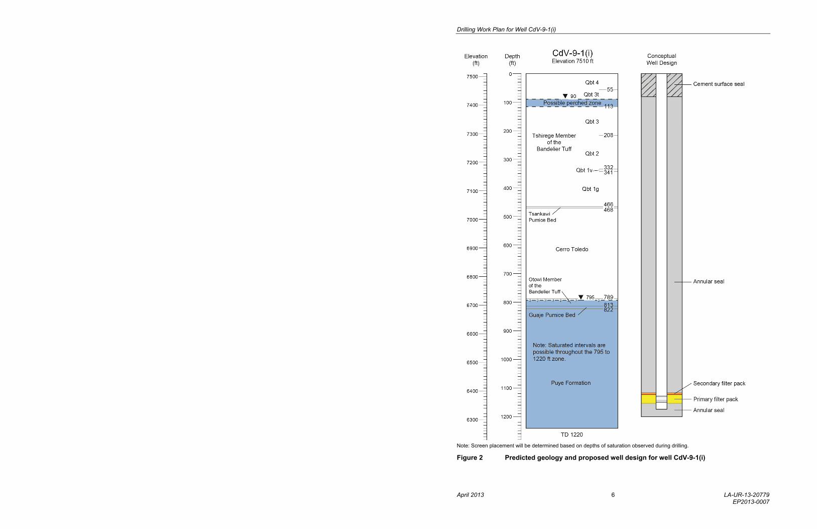
The depth to the top of the perched intermediate zone of saturation at CdV-9-1(i) is expected to be approximately 795 ft. The target depth for the borehole is 1220 ft, about 30 ft below the projected bottom of the lower screen at CdV-16-4ip and about 75 ft above the expected elevation of the regional aquifer. The depth and occurrence of perched and regional groundwater is uncertain, and the target depth may be adjusted once the water depth and producing intervals are evaluated at this location.
Figure 2 shows the predicted geology, expected groundwater-producing intervals, and proposed well design for CdV-9-1(i). The well is tentatively designed with a single well screen to be placed near the depth of CdV-16-4ip screen 2 (projected to be 1156–1187 ft) in Puye Formation deposits. Alternatively, the uppermost producing interval corresponding to the highest RDX (hexahydro-1,3,5-trinitro-1,3,5-triazine) screening results observed during drilling may be selected for screen placement. Final selection of well screen length and position will be based on data obtained during drilling, including information from lithologic logs of cuttings, water-level measurements, RDX screening results, video logs, geophysical logs, and drill crew observations.
A final well design will be based on hydrogeological conditions encountered during drilling, and a revised well design document will be submitted to NMED for approval before well construction begins.
Conceptual Model The conceptual model for the 260 Outfall area is of a line-source recharge to the deep-perched saturated zone symmetric along the east-west trace of Cañon de Valle downstream from the outfall. The potential exists for zones of contaminated perched-intermediate groundwater similar to those south of Cañon de Valle to be present north of the canyon. Installation of well CdV-9-1(i) will further refine the conceptual model.
Drilling Approach Drilling will be conducted with methods selected to optimize the potential of completing the well without using drilling additives in, or immediately above, the target zone of saturation. A combination of open-hole and casing-advance methods will be employed. Each interval of open hole or casing advance will be optimized to meet well objectives. Casing will be advanced through the deep-perched saturated interval to evaluate relative groundwater flow and to collect RDX screening samples. Estimates of groundwater production will be made during the advancement of each 20-ft section of drill casing. A screening sample will be air-lifted at startup after each new joint connection.

Drilling Work Plan for Well CdV-9-1(i)
April 2013 2 LA-UR-13-20779 EP2013-0007
Potential Drilling Fluids, Composition, and Use
Fluids and additives that may be used to facilitate drilling will be consistent with those previously used in the drilling program at the Laboratory and already characterized geochemically. Fluids and additives previously authorized for use by NMED include
potable municipal water supply to aid in the delivery of other drilling additives and cooling the drill bit;
QUIK-FOAM, a blend of alcohol ethoxy sulfates, used as a foaming agent; and
AQF-2, an anionic surfactant, used as a foaming agent.
Complete records will be maintained detailing the type, amount, and volume of drilling fluid used, the depth at which drilling fluid is added to the borehole, the amount in storage in the borehole, and the recovery volume of drilling fluid. No drilling fluids, except potable municipal water, will be used within 100 ft of the perched-intermediate zone of saturation. If the target zone cannot be reached without the addition of drilling fluids, the situation will be discussed with NMED. No chemicals, other than those listed above, will be added without NMED’s approval.
Hydrogeologic and Geochemical Objectives
The primary objective is to characterize the deep-perched zone of saturation and to monitor groundwater quality downgradient of the 260 Outfall at TA-16.
A secondary objective is to establish water levels and gradients in the deep-perched saturated zone in this area.
Potential Groundwater Occurrence and Detection
Potential Perched Water: Based on drilling observations at wells in the area, perched water is expected at this location. The predicted depths of groundwater are 90–113 ft and 795–1220 ft below ground surface (bgs) (total drilled depth). The depth and length of saturated sections within the 795–1220-ft interval are unknown.
Regional: Drilling will terminate at 1220 ft bgs, approximately 75 ft above regional saturation.
Methods to detect perched groundwater may include driller’s observations, water-level measurements, borehole video, borehole geophysics, and monitoring for pressure responses in nearby wells.
Core Sampling No core collection is planned.
Perched Groundwater Screening Sampling
A groundwater screening sample will be air-lifted during drilling from the first deep-intermediate zone of saturation. The screening sample will be analyzed for cations/metals (dissolved and total) and anions (dissolved) by the Earth and Environmental Sciences (EES) Division’s Geochemistry and Geomaterials Research Laboratory (GGRL) and for HE and tritium by off-site laboratories. Additionally, RDX screening samples will be collected every 20 ft while drilling through the deep-perched interval. These samples will be submitted to the EES Division’s GGRL for RDX analysis with a minimum detection limit of 2 ppb.
Perched Groundwater Characterization Sampling
Groundwater samples will be collected from the completed well between 10 d and 60 d after well development in accordance with the Compliance Order on Consent. These samples will be analyzed for the full suite of TA-16–related constituents, including tritium; metals/cations; general inorganic chemicals; volatile organic compounds; semivolatile organic compounds; HE compounds, including RDX and related degradation products; as well as stable isotopes.
Subsequent groundwater samples will be collected in accordance with the requirements of the Interim Facility-Wide Groundwater Monitoring Plan (the Interim Plan).

Drilling Work Plan for Well CdV-9-1(i)
LA-UR-13-20779 3 April 2013 EP2013-0007
Geophysical Testing
The Laboratory’s borehole video camera, natural gamma, and induction tools will be used in the open borehole if conditions allow.
A full suite of geophysical logs will be run, if required, for proper placement of the screen. The logs will be collected by Schlumberger, Inc., and for open-hole conditions, will include accelerator porosity sonde (neutron porosity), array induction, combined magnetic resonance, natural and spectral gamma, and formation microimager logs. In cased portions of the borehole, neutron porosity, triple lithodensity, elemental capture, natural gamma, and spectral gamma logs will be collected. These logs will be used to characterize the hydraulic properties of saturated rocks in the regional aquifer.
The geophysical logs also will be used to select the well screen depths. The suite and timing of geophysical logging will depend on borehole conditions.
Well Completion Design
Figure 2 shows the conceptual well design and predicted geology for well CdV-9-1(i).
Well Development The well may be developed by both mechanical and chemical means. Mechanical means include swabbing, bailing, and pumping. Chemical means include the use of additives to remove clays and/or chlorination to kill bacteria introduced during well completion.
After initial swabbing and bailing, a submersible pump will be used to complete the development process.
Water-quality parameters will be measured in a flow-through cell. The parameters to be monitored are pH, specific conductance, dissolved oxygen, temperature, turbidity, oxidation-reduction potential, and total organic carbon (TOC).
If the Laboratory is unable to bring the water-quality parameters to within the limits specified below, the use of chemical well development may be discussed with NMED. No chemicals will be added without NMED’s approval.
Chemical means that may be used include sodium acid pyrophosphate and AQUACLEAR PFD to remove clays and/or chlorination.
Well development will be considered complete when target water-quality parameters are met and a volume of water equivalent to that which was introduced into the aquifer during drilling and construction is removed. The target water-quality parameters are turbidity <5 nephelometric turbidity units, TOC <2 ppm, and other parameters stable.
Hydraulic Testing Hydraulic testing will be considered if a sufficiently robust zone within the aquifer is encountered. The most likely test will be a 24-h constant-rate pumping test.
Investigation-Derived Waste Management
Investigation-derived waste (IDW) will be managed in accordance with the requirements in P-409, Waste Management, and EP-DIR-SOP-10021, Characterization and Management of Environmental Programs Waste, available at http://www.lanl.gov/community-environment/environmental-stewardship/plans-procedures.php. This standard operating procedure incorporates the requirements of applicable U.S. Environmental Protection Agency and NMED regulations, U.S. Department of Energy orders, and Laboratory requirements. The primary waste streams include drill cuttings, drilling water, development water, purge water, decontamination water, and contact waste.

Drilling Work Plan for Well CdV-9-1(i)
April 2013 4 LA-UR-13-20779 EP2013-0007
Investigation-Derived Waste Management (continued)
Drill cuttings will be managed in accordance with the NMED-approved Notice of Intent (NOI) Decision Tree for Land Application of IDW Solids from Construction of Wells and Boreholes (November 2007). Drilling, purge, and development waters will be managed in accordance with the NMED-approved NOI Decision Tree for Drilling, Development, Rehabilitation, and Sampling Purge Water (November 2006). Initially, drill cuttings and drilling water will be stored in lined pits. The cuttings may or may not contain residue of drilling/well completion additives (e.g., drilling foam and bentonite clay). The contents of the pits will be characterized with direct sampling following completion of drilling activities, and waste determinations will be made from validated data. If validated analytical data show these wastes cannot be land-applied, they will be removed from the pit, containerized, and placed in accumulation areas appropriate to the type of waste. Cuttings, drilling water, development water, and purge water that cannot be land-applied and are designated as hazardous waste will be sent to an authorized treatment, storage, or disposal facility within 90 d of containerization. Development water, purge water, and decontamination water will be containerized separately at their point of generation, placed in an accumulation area appropriate to the type of waste, and directly sampled. Contact waste will be containerized at the point of generation, placed in an appropriate accumulation area, and characterized using acceptable knowledge of the media with which it came in contact.
Schedule Well CdV-9-1(i) is proposed for completion by October 31, 2013. This date assumes that additional funding will be available beginning April 1, 2013, to support the proposed completion date.
Monitoring conducted after CdV-9-1(i) is installed will be implemented under the Interim Plan and will support investigations and corrective actions at TA-16.
REFERENCES
The following list includes all documents cited in this plan. Parenthetical information following each reference provides the author(s), publication date, and ER ID. This information is also included in text citations. ER IDs are assigned by the Environmental Programs Directorate’s Records Processing Facility (RPF) and are used to locate the document at the RPF and, where applicable, in the master reference set.
Copies of the master reference set are maintained at the NMED Hazardous Waste Bureau and the Directorate. The set was developed to ensure that the administrative authority has all material needed to review this document, and it is updated with every document submitted to the administrative authority. Documents previously submitted to the administrative authority are not included.
LANL (Los Alamos National Laboratory), March 2012. “Technical Area 16 Well Network Evaluation and Recommendations,” Los Alamos National Laboratory document LA-UR-12-1082, Los Alamos, New Mexico. (LANL 2012, 213573)
NMED (New Mexico Environment Department), June 20, 2012. “Approval with Modifications, Technical Area 16 Well Network Evaluation and Recommendations,” New Mexico Environment Department letter to P. Maggiore (DOE-LASO) and M.J. Graham (LANL) from J.E. Kieling (NMED-HWB), Santa Fe, New Mexico. (NMED 2012, 520747)

Drilling Work Plan for Well CdV-9-1(i)
LA-UR-13-20779 5 April 2013 EP2013-0007
Figure 1 Proposed location of well CdV-9-1(i)
Drilling Work Plan for Well CdV-9-1(i)
April 2013 6 LA-UR-13-20779 EP2013-0007
Note: Screen placement will be determined based on depths of saturation observed during drilling.
Figure 2 Predicted geology and proposed well design for well CdV-9-1(i)