enter/exit programming mode - support technique aures ps-50... · this can be determined by turning...
TRANSCRIPT


Enter/Exit Programming Mode
(This barcode is also found at back cover page.)
Framed values are default values.

IMPORTANT NOTICE No warranty of any kind is made in regard to this material, including, but not limited to, implied warranties of merchantability or fitness for any particular purpose. We are not liable for any errors contained herein nor for incidental or consequential damages in connection with furnishing, performance or use of this material. We shall be under no liability in respect of any defect arising from fair wear and tear, willful damage, negligence, abnormal working conditions, failure to follow the instructions and warnings, or misuse or alteration or repair of the products without written approval. No part of this document may be reproduced, transmitted, stored in a retrieval system, transcribed, or translated into any human or computer or other language in any form or by any means electronic, mechanical, magnetic, optical, chemical, biologi- cal, manual or otherwise, except for brief passages which may be quoted for purposes of scholastic or literary review, without express written consent and authorization. We reserve the right to make changes in product design without reservation and without notification. The material in this guide is for information only and is subject to change without notice. All trademarks mentioned herein, registered or otherwise, are the properties of their owners. Specification or version may be subject to change without notice. The actual specification and version are based on the product delivered. General handling precautions • Do not dispose of the scanner in fire. • Do not put the scanner directly in the sun or by any heat source. • Do not use or store the scanner in a very humid place. • Do not drop the scanner or allow it to collide violently with other objects. • Do not take the scanner apart without authorization. Copyright © 2008. All rights reserved. Printed In May, 2008
Radio Notice Some equipment generates uses and can radiate radio frequency energy. If not installed and used in accordance with the instructions in this manual, it may cause interference to radio communications. The equipment has been tested and found to comply with the limits for a Class A computing device pursuant to EN55022 and 47 CFR, Part 2 and Part 15 of the FCC rules. These specifications are designed to provide reasonable protection against interference when operated in a commercial environment. Radio and Television Interference Operation of this equipment in a residential area can cause interference to radio or television reception. This can be determined by turning the equipment off and on. The user is encouraged to try to correct the interference by one or more of the following measures: Reorient the receiving antenna. Relocate the device with respect to the receiver. Move the device away from the receiver. Plug the device into a different outlet so that the device and the receiver are on different branch circuits. f necessary the user may consult the manufacturer, and authorized dealer, or experienced radio/television technician for additional suggestions. The user may find the following booklet prepared by the Federal Communications Commission helpful: “How to Identify and Resolve Radio-TV Interference Problems.” This booklet is available from the U.S. Government Printing Office, Washington, DC 20402 U.S.A., Stock No. 004000003454. For CE-countries This scanner is in conformity with CE standards. Please note that an approved, CE-marked power supply unit should be used in order to maintain CE conformance.
Laser Safety The laser scanner complies with safety standard IEC 60825-1 for a Class I laser produce. It also complies with CDRH as applicable to a Class IIa laser product. Avoid long term staring into direct laser light. Radiant Energy: The laser scanner uses one low-power visible laser diodes operating at 650nm in an opto-mechanical scanner resulting in less than 3.9μW radiated power as observed through a 7mm aperture and averaged over 10 seconds. Do not attempt to remove the protective housing of the scanner, as un-scanned laser light with a peak output up to 0.8mW would be accessible inside. Laser Light Viewing: The scan window is the only aperture through which laser light may be observed from this product. A failure of the scanner motor, while the laser diode continues to emit a laser beam, may cause emission levels to exceed those for safe operation. The scanner has safeguards to prevent this occurrence. If, however, a stationary laser beam is emitted, the failing scanner should be disconnected from its power source immediately. Adjustments: Do not attempt any adjustments or alteration of this product. Do not remove the protective housing of the scanner. There are no user-serviceable parts inside. Caution: Use of controls or adjustments or performance of procedures other than those specified herein may result in hazardous laser light exposure. Optical: The use of optical instruments with this product will increase the eye hazard. Optical instruments include binoculars, magnifying glasses, and microscopes but do not include normal eye glasses worn by the user.

TABLE OF CONTENTS Introduction.................................................................................................... 1 Changing the scanner setting........................................................................ 2 Default parameters........................................................................................ 2 Default values of operating parameters................................................ 2 Default values of keyboard emulation parameters setting…. ............... 3 Default values of RS-232C serial communication parameters ............. 3 Default values of USB emulation parameters....................................... 3 Default values of wand emulation parameters...................................... 3 Default values of decoding parameters ................................................ 4 Program procedure using barcode menus ........................................... 5 System setting............................................................................................... 6 Return to factory default ....................................................................... 7 Display firmware version ...................................................................... 7 Abort..................................................................................................... 8 Return to PC/AT default........................................................................ 8 Return to RS-232 default...................................................................... 9 Return to USB default........................................................................... 9 Return to wand emulation default ....................................................... 10 Return as customer default ................................................................ 10 Save as customer default ....................................................................11 Sleep timeout selection ............................................................................... 12 Same code delay time................................................................................. 20 Beeper sound selection............................................................................... 27 Barcode identifier code setting .................................................................... 38 Barcode identifier code selection........................................................ 39 Set message format with code identifier............................................. 40 Enable identifier code table as AIM standard ..................................... 40 Barcode identifier code setting ........................................................... 41 Message delay ............................................................................................ 47 Character delay ........................................................................................... 50 Interface communication setting.................................................................. 54 RS-232C interface configuration ........................................................ 55 Baud rate setting ......................................................................... 55 Data bit setting ............................................................................ 59 Stop bit setting............................................................................. 60 Parity bit setting........................................................................... 61 Handshaking protocol.................................................................. 64 ACK/NAK response time setting ................................................. 67 Message terminator for RS-232C................................................ 73 Keyboard wedge interface configuration ............................................ 77 Message terminator for keyboard wedge .................................... 77 Keyboard language selection ...................................................... 79 Capital lock setting ...................................................................... 85 Function key emulation ............................................................... 86
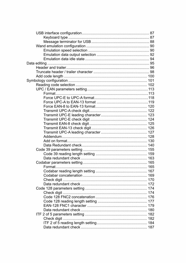
USB interface configuration................................................................ 87 Keyboard type ............................................................................. 87 Message terminator for USB ....................................................... 88 Wand emulation configuration ............................................................ 90 Emulation speed selection .......................................................... 90 Emulation data output selection .................................................. 92 Emulation data idle state ............................................................. 94 Data editing ................................................................................................. 95 Header and trailer............................................................................... 96 Truncate header / trailer character ..................................................... 98 Add code length ............................................................................... 100 Symbology configuration ........................................................................... 101 Reading code selection .................................................................... 102 UPC / EAN parameters setting..........................................................113 Format........................................................................................113 Force UPC-E to UPC-A format...................................................118 Force UPC-A to EAN-13 format .................................................119 Force EAN-8 to EAN-13 format................................................. 120 Transmit UPC-A check digit....................................................... 122 Transmit UPC-E leading character............................................ 123 Transmit UPC-E check digit ...................................................... 124 Transmit EAN-8 check digit ....................................................... 125 Transmit EAN-13 check digit ..................................................... 126 Transmit UPC-A leading character ............................................ 127 Addendum................................................................................. 128 Add on format............................................................................ 130 Data Redundant check.............................................................. 140 Code 39 parameters setting ............................................................. 155 Code 39 reading length setting ................................................. 159 Data redundant check ............................................................... 163 Codabar parameters setting ............................................................. 165 Format....................................................................................... 165 Codabar reading length setting ................................................. 167 Codabar concatenation ............................................................. 169 Check digit ................................................................................ 170 Data redundant check ............................................................... 172 Code 128 parameters setting ........................................................... 174 Check digit ................................................................................ 174 Code 128 FNC2 concatenation ................................................. 176 Code 128 reading length setting ............................................... 177 EAN-128 FNC1 character ......................................................... 179 Data redundant check ............................................................... 180 ITF 2 of 5 parameters setting ........................................................... 182 Check digit ................................................................................ 182 ITF 2 of 5 reading length setting................................................ 184 Data redundant check ............................................................... 187
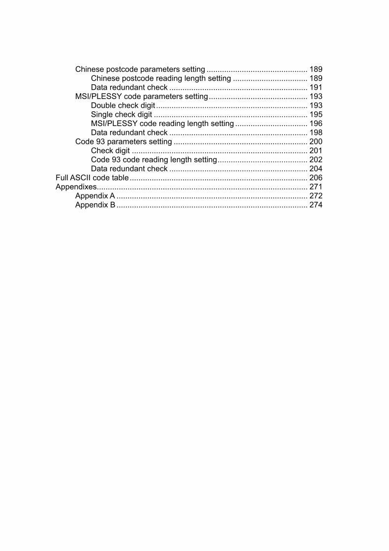
Chinese postcode parameters setting .............................................. 189 Chinese postcode reading length setting .................................. 189 Data redundant check ............................................................... 191 MSI/PLESSY code parameters setting............................................. 193 Double check digit ..................................................................... 193 Single check digit ...................................................................... 195 MSI/PLESSY code reading length setting ................................. 196 Data redundant check ............................................................... 198 Code 93 parameters setting ............................................................. 200 Check digit ................................................................................ 201 Code 93 code reading length setting......................................... 202 Data redundant check ............................................................... 204 Full ASCII code table................................................................................. 206 Appendixes................................................................................................ 271 Appendix A ....................................................................................... 272 Appendix B ....................................................................................... 274

1 ADVANCED PROGRAMMING GUIDE
1. INTRODUCTION This is a advanced programming guide for varies omnidirectional laser scanners, this guide contains a series of programming barcode labels, and by scanning these codes, it can make configurations to the scanners. This allows decoding options and interface protocols to be tailored to a specific application. The configuration is stored in non-volatile memory and will not be lost by removing power from the scanner.. Other than specified in this guide, for any special functions or specifications, please contact your dealer for details. The scanner must be properly powered before programming. For RS-232C type scanners, an external power adapter must be used to supply DC power to the scanner. If a keyboard emulation type scanner is used with an IBM PC/XT/AT, PS/2 or any fully compatible computers, power will be drawn from the keyboard port, therefore no external power adapter is required. If keyboard emulation type scanner is used with any other non IBM PC compatible computers, an external power adapter may be required.
Under the programming mode, the laser scanner will acknowledge a good and valid reading with a short beep. It will give long beeps for either an invalid or bad reading.

2 ADVANCED PROGRAMMING GUIDE
2. CHANGE THE SCANNER SETTING In order to change the scanner setting, please follow the steps below: 1. Scan the “Enter/Exit Programming Mode” barcode, there will be 2 beeps
(low-high) indicating ready to make settings. 2. Scan barcodes for the desired feature (1 beep) 3. Scan the “Enter/Exit Programming Mode” barcode again to save the
configuration, there will be 2 beeps (long---short) indicating settings successfully.
After reading a valid barcode in programming mode the scanner will gave a high beep. 3. DEFAULT PARAMETERS This table gives the default settings of all the programmable parameters. The default settings will be restored whenever the "Reset" programming label is scanned and the laser scanner is in programming.
Default Values of Operating Parameters
Function Default Sleep mode
Motor sleep mode After 30 minutes Laser sleep mode After 10 minutes
Scanner timing Same code delay 200msec
Beeper Tone Frequency medium Duration 50msec
Code Identifiers Code ID off Code 39 M ITF 2 of 5 I Chinese post code H UPC-A A UPC-E E EAN-13 F EAN-8 FF Codabar N Code 128 K Code 93 L MSI/Plessy P
3 ADVANCED PROGRAMMING GUIDE
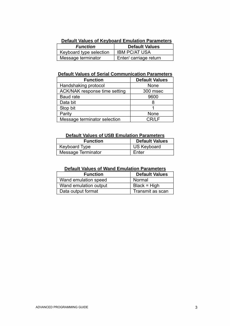
Default Values of Keyboard Emulation Parameters Function Default Values
Keyboard type selection IBM PC/AT USA Message terminator Enter/ carriage return
Default Values of Serial Communication Parameters Function Default Values
Handshaking protocol None ACK/NAK response time setting 300 msec Baud rate 9600 Data bit 8 Stop bit 1 Parity None Message terminator selection CR/LF
Default Values of USB Emulation Parameters Function Default Values
Keyboard Type US Keyboard Message Terminator Enter
Default Values of Wand Emulation Parameters Function Default Values
Wand emulation speed Normal Wand emulation output Black = High Data output format Transmit as scan
4 ADVANCED PROGRAMMING GUIDE
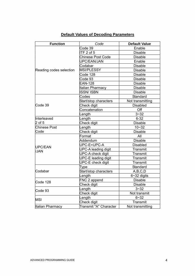
Default Values of Decoding Parameters
Function Code Default Value Code 39 Enable ITF 2 of 5 Disable Chinese Post Code Disable UPC/EAN/JAN Enable Codabar Disable MSI/PLESSY Disable Code 128 Disable Code 93 Disable EAN-128 Disable Italian Pharmacy Disable
Reading codes selection
ISSN/ ISBN Disable Codes Standard Start/stop characters Not transmitting Check digit Disabled Concatenation Off
Code 39
Length 3~32 Length 6-32 Interleaved
2 of 5 Check digit Disable Length 10~32 Chinese Post
Code Check digit Disable Format All Addendum Disable UPC-E=UPC-A Disabled UPC-A leading digit Transmit UPC-A check digit Transmit UPC-E leading digit Transmit
UPC/EAN /JAN
UPC-E check digit Transmit Type Standard Start/stop characters A,B,C,D Codabar Length 6~32 digits FNC 2 append Disable Code 128 Check digit Disable Length 3~32 Code 93 Check digit Not transmit Length 6~32 MSI Check digit Transmit
Italian Pharmacy Transmit "A" Character Not transmitting

5 ADVANCED PROGRAMMING GUIDE
PROGRAM PROCEDURE USING BARCODE MENUS
Read Enter/Exit programming mode barcode to start of configuration
Change scanner setting by scanning mode
Select code 39 full ASCII table?
Read “Set”barcode to confirm
Read Enter/Exit programming mode barcode to save and exit
Yes
No
6 ADVANCED PROGRAMMING GUIDE
System Setting
The series scanner is a multi-interface communication scanner. If you had ordered only the one type of interface, the device is configured in the interface
requested, i.e. RS-232C, keyboard wedge, wand emulation or USB. If not requested, the default interface is set in keyboard wedge interface (PC/AT);
using this section to change interfaces.
7 ADVANCED PROGRAMMING GUIDE
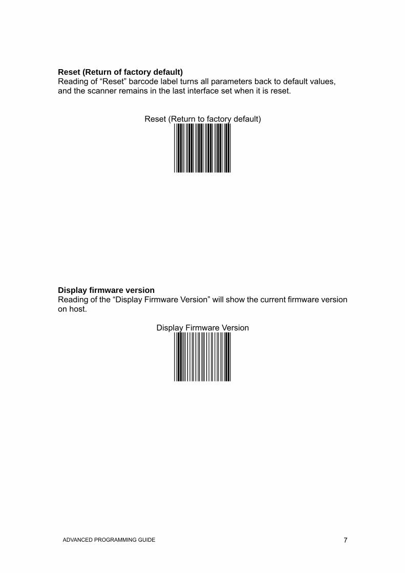
Reset (Return of factory default) Reading of “Reset” barcode label turns all parameters back to default values, and the scanner remains in the last interface set when it is reset.
Reset (Return to factory default)
Display firmware version Reading of the “Display Firmware Version” will show the current firmware version on host.
Display Firmware Version

8 ADVANCED PROGRAMMING GUIDE
Abort (Exit programming mode) Reading of the “Abort” barcode label discards all the parameters read prior to scan the “Enter/Exit of Programming Mode”.
Abort (Exit programming mode)
”.
Return to PC/AT default This barcode allows setting in keyboard wedge interface for IBM PC AT/PS/2 and compatibles.
Return to PC/AT default

9 ADVANCED PROGRAMMING GUIDE
Return to RS-232 default The RS-232C interface scanner is often used when connecting to the serial port of a PC or terminal, reading the barcode to set the scanner into RS-232 interface.
Return to RS-232 default
Return to USB default Reading of “Return to USB default” sets the device into USB interface support.
Return to USB default
10 ADVANCED PROGRAMMING GUIDE
Return to wand emulation default The Wand emulation is achieved by decoding a scanned barcode and then encoding it again, so that the output is readily decoded by an external decoder designed for processing of wand data.
Return to wand emulation default
Return as customer default Reading of the label sets the device back to customer saved parameter settings.
Return as customer default
.
11 ADVANCED PROGRAMMING GUIDE
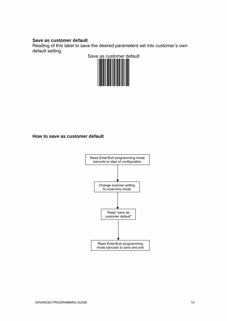
Save as customer default Reading of this label to save the desired parameters set into customer’s own default setting.
Save as customer default
How to save as customer default
Read Enter/Exit programming mode barcode to start of configuration
Change scanner setting by scanning mode
Read “save as customer default”
Read Enter/Exit programming mode barcode to save and exit

12 ADVANCED PROGRAMMING GUIDE
Sleep Timeouts Selection
In the section, user can set both laser and/or motor to enter into sleep mode. The timeout programming labels will allow users to set the different time frame before entering into laser and/or motor sleep mode. The feature reduces power
consumption and prolongs scanner life time.
NOTE: Laser always enters sleep mode before motor.
If the motor timeout sets shorter than the motor Timeout, then laser enters sleep mode as motor enters sleep mode.

13 ADVANCED PROGRAMMING GUIDE
Motor sleep mode off
Motor sleep time 5 min.

14 ADVANCED PROGRAMMING GUIDE
Motor sleep time 10 min.
Motor sleep time 20 min.

15 ADVANCED PROGRAMMING GUIDE
Motor sleep time 30 min.
Motor sleep time 60 min.

16 ADVANCED PROGRAMMING GUIDE
Laser sleep mode off
Laser sleep time 5 min.

17 ADVANCED PROGRAMMING GUIDE
Laser sleep time 10 min.
Laser sleep time 15 min.

18 ADVANCED PROGRAMMING GUIDE
Laser sleep time 20 min.
Laser sleep time 25 min.

19 ADVANCED PROGRAMMING GUIDE
Laser sleep time 30 min.

20 ADVANCED PROGRAMMING GUIDE
Same Code Delay Time
This parameter sets the minimum time allowed between decodes of the same label.

21 ADVANCED PROGRAMMING GUIDE
Same code delay time 50 msec.
Same code delay time 100 msec.

22 ADVANCED PROGRAMMING GUIDE
Same code delay time 200 msec.
Same code delay time 300 msec.

23 ADVANCED PROGRAMMING GUIDE
Same code delay time 400 msec.
Same code delay time 500 msec.

24 ADVANCED PROGRAMMING GUIDE
Same code delay time 600 msec.
Same code delay time 700 msec.

25 ADVANCED PROGRAMMING GUIDE
Same code delay time 800 msec.
Same code delay time 900 msec.

26 ADVANCED PROGRAMMING GUIDE
Same code delay time 1000 msec.
Same code delay time infinite

27 ADVANCED PROGRAMMING GUIDE
Beeper Sound Selection
This section includes all setting labels for beeper sound, settings includes tone frequency, volume, duration time, power on beep
enable/disable, and enable/disable sound when enter sleep mode. .

28 ADVANCED PROGRAMMING GUIDE
Led/Beep after transmission
Led/Beep before transmission

29 ADVANCED PROGRAMMING GUIDE
Power-up tone enable
Power-up tone disable

30 ADVANCED PROGRAMMING GUIDE
Sleep sound
Sleep silent

31 ADVANCED PROGRAMMING GUIDE
Medium beeper tone
Low beeper tone

32 ADVANCED PROGRAMMING GUIDE
High beeper tone
Speaker disable

33 ADVANCED PROGRAMMING GUIDE
Beeper sound duration (100msec)
Beeper sound duration (50msec)

34 ADVANCED PROGRAMMING GUIDE
Beeper sound duration (20msec)
Beeper sound duration (5msec)

35 ADVANCED PROGRAMMING GUIDE
Beeper sound duration 200msec
Beeper sound duration 500msec

36 ADVANCED PROGRAMMING GUIDE
Loud beeper volume
Medium beeper volume

37 ADVANCED PROGRAMMING GUIDE
Low beeper volume
38 ADVANCED PROGRAMMING GUIDE
Barcode Identifier Code Setting
The scanner can transmit maximum 2 digits barcode identifier code for different type of barcodes. Using enable or disable identifier setting barcode to choose transmit or do not transmit barcode identifier code. The procedure is as follows: 1.) Scan “Enter/Exit Programming Mode” label 2.) Scan “Barcode Identifier Setting Code” label 3.) Scan the new code mark from ASCII table (maximum 2 digits). For example,
if “AB” is the code mark then scan “A” and “B” 4.) Scan “Save Setting to Confirm” label 5.) Scan “Enter/Exit Programming Mode” label
.
39 ADVANCED PROGRAMMING GUIDE
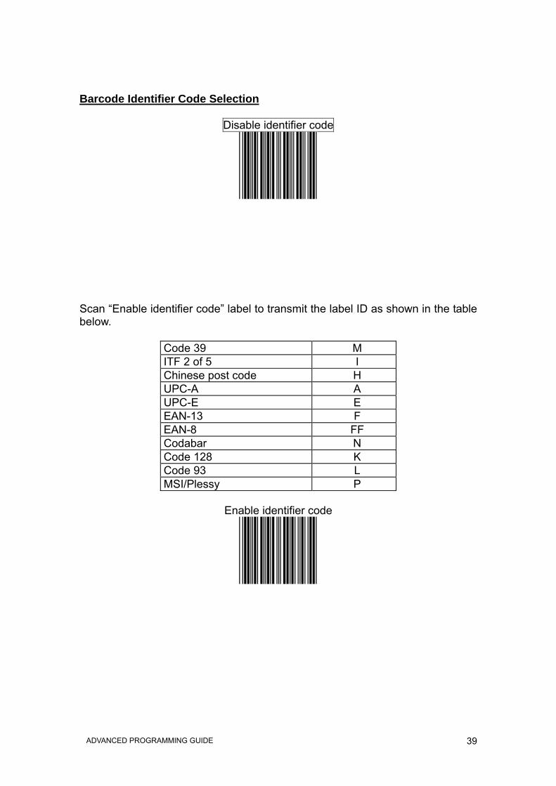
Barcode Identifier Code Selection
Disable identifier code
Scan “Enable identifier code” label to transmit the label ID as shown in the table below.
Code 39 M ITF 2 of 5 I Chinese post code H UPC-A A UPC-E E EAN-13 F EAN-8 FF Codabar N Code 128 K Code 93 L MSI/Plessy P
Enable identifier code

40 ADVANCED PROGRAMMING GUIDE
Set Message Format with Code Identifier
I S 0 2
Code Code identifier UPC-A A UPC-E E EAN-8 FF EAN-13 F CODE 39 * CODBAR % ITF 2 OF 5 i CODE 93 & CODE 128 # MSI/PLESSY @ EAN-128 P
Enable Identifier Code Table as AIM Standard

41 ADVANCED PROGRAMMING GUIDE
Barcode Identifier Code Setting
Code 39 identifier code setting
ITF 2 of 5 identifier code setting

42 ADVANCED PROGRAMMING GUIDE
Chinese Post code identifier code setting
UPC-E identifier code setting

43 ADVANCED PROGRAMMING GUIDE
UPC-A identifier code setting
EAN-13 identifier code setting

44 ADVANCED PROGRAMMING GUIDE
EAN-8 identifier code setting
Codabar identifier code setting

45 ADVANCED PROGRAMMING GUIDE
Code 128 identifier code setting
Code 93 identifier code setting

46 ADVANCED PROGRAMMING GUIDE
MSI identifier code setting
Save setting to confirm

47 ADVANCED PROGRAMMING GUIDE
Message delay
In this section contains different delay time frame between two consecutive messages. This delay will be added before each date transmission.

48 ADVANCED PROGRAMMING GUIDE
Inter message delay 0 ms
Inter message delay 100 ms

49 ADVANCED PROGRAMMING GUIDE
Inter message delay 500 ms
Inter message delay 1000 ms

50 ADVANCED PROGRAMMING GUIDE
Character delay
This option governs delay time between two consecutive characters; the delay time can be altered by scanning the following labels.

51 ADVANCED PROGRAMMING GUIDE
Character delay 5 ms
Inter character delay 0 ms

52 ADVANCED PROGRAMMING GUIDE
Inter character delay 10 ms
Inter character delay 20 ms

53 ADVANCED PROGRAMMING GUIDE
Inter character delay 50 ms

54 ADVANCED PROGRAMMING GUIDE
Interface Communication Setting
This section contains labels to configure the scanner to user’s host terminal. The following interfaces are supported:
*Keyboard wedge *RS-232C interface
*USB interface *Wand emulation
55 ADVANCED PROGRAMMING GUIDE
RS-232C interface configuration
1. Baud Rate setting
Baud Rate 38400
Baud Rate 19200

56 ADVANCED PROGRAMMING GUIDE
Baud Rate 9600
Baud Rate 4800

57 ADVANCED PROGRAMMING GUIDE
Baud Rate 2400
Baud Rate 1200

58 ADVANCED PROGRAMMING GUIDE
Baud Rate 57600
Baud Rate 115200

59 ADVANCED PROGRAMMING GUIDE
2. Date Bit Setting 7 data bit
8 data bit

60 ADVANCED PROGRAMMING GUIDE
3. Stop Bit Setting 1 Stop bit
2 Stop bit

61 ADVANCED PROGRAMMING GUIDE
4. Parity Bit Setting Even Parity
Odd Parity

62 ADVANCED PROGRAMMING GUIDE
Mark Parity
Space Parity

63 ADVANCED PROGRAMMING GUIDE
None Parity

64 ADVANCED PROGRAMMING GUIDE
5. Handshaking Protocol The RS-232C type scanner supports four handshaking protocols. With these options of communication protocol, users can tailor the scanner to meet the requirement of most systems. These handshaking protocols are: *None: The scanner will transmit any read data unconditionally. The scanner will not check the receiving device or the transmitted message. *RTS/CTS: Under this handshaking protocol, the scanner use the RTS pin to instruct the connected device to transmit data and test the CTS pin for readiness of the connected device to receive data. *ACK/NAK: While selecting this option, the scanner waits for an ACK or NAK signal from the host computer after each data transmission. Normally, the scanner will temporarily stored the scanned data in the memory buffer before receiving the ACK or NAK signal. If the ACK signal is received, it will clear the transmitted data and continue to send the next data. In case of the NAK signal is received, it will repeat to transmit the same data until receiving the ACK signal. *Xon/Xoff: During the data communication, if a scanner receives an Xoff (ASCII 013H), it will stop the transmission at once. The scanner waits for a Xon (ASCII 01H) to start the transmission again.

65 ADVANCED PROGRAMMING GUIDE
None handshaking
ACK/NAK

66 ADVANCED PROGRAMMING GUIDE
Xon/Xoff
RTS/CTS

67 ADVANCED PROGRAMMING GUIDE
6. ACK/NAK Response Time Setting ACK/NAK response time 300ms
ACK/NAK response time 500ms

68 ADVANCED PROGRAMMING GUIDE
ACK/NAK response time 1s
ACK/NAK response time 2s

69 ADVANCED PROGRAMMING GUIDE
ACK/NAK response time 3s
ACK/NAK response time 5s

70 ADVANCED PROGRAMMING GUIDE
ACK/NAK response time Infinity
Disable ACK/NAK timeout beeper

71 ADVANCED PROGRAMMING GUIDE
Enable ACK/NAK timeout beeper
Enable beeper on<BEL> character

72 ADVANCED PROGRAMMING GUIDE
Ignore beep on <BEL>character
73 ADVANCED PROGRAMMING GUIDE
7. Message terminator for RS-232C The series RS-232C type scanner can be programmed to append a terminator to every message sent via the serial port. Different terminator will be appended at the end of message sent from the serial port.
RS-232 message terminator-none
RS-232 message terminator-CR/LF

74 ADVANCED PROGRAMMING GUIDE
RS-232 message terminator-CR
RS-232 message terminator-LF

75 ADVANCED PROGRAMMING GUIDE
RS-232 message terminator-H tab
RS-232 message terminator-STX/ETX

76 ADVANCED PROGRAMMING GUIDE
RS-232 message terminator-EOT

77 ADVANCED PROGRAMMING GUIDE
Keyboard wedge interface configuration 1. Message terminator for keyboard Wedge
Keyboard terminator---none
Keyboard terminator---Enter

78 ADVANCED PROGRAMMING GUIDE
Keyboard terminator---H-TAB
79 ADVANCED PROGRAMMING GUIDE
2. Keyboard Language Selection Enable International keyboard type
(Alt method)
Keyboard language support---USA

80 ADVANCED PROGRAMMING GUIDE
Keyboard language support---Germany
Keyboard language support---UK

81 ADVANCED PROGRAMMING GUIDE
Keyboard language support---French
Keyboard language support---Spanish

82 ADVANCED PROGRAMMING GUIDE
Keyboard language support--- Italian
Keyboard language support--- Swiss

83 ADVANCED PROGRAMMING GUIDE
Keyboard language support---Swedish
Keyboard language support---Japanese

84 ADVANCED PROGRAMMING GUIDE
Keyboard language support---Belgium

85 ADVANCED PROGRAMMING GUIDE
3. Capital Lock Select the suitable code to match your keyboard caps lock status
Capital lock on
Capital lock off
86 ADVANCED PROGRAMMING GUIDE
4. Function Key Emulation In this section, user can emulate Function keys, Arrow keys, and many other “extended” keys. An IBM compatible keyboard does not translate to ASCII characters; it can be concatenated with input data as header and/or trailer. (see Appendix B)
Function key emulation enable
Function key emulation disable
87 ADVANCED PROGRAMMING GUIDE
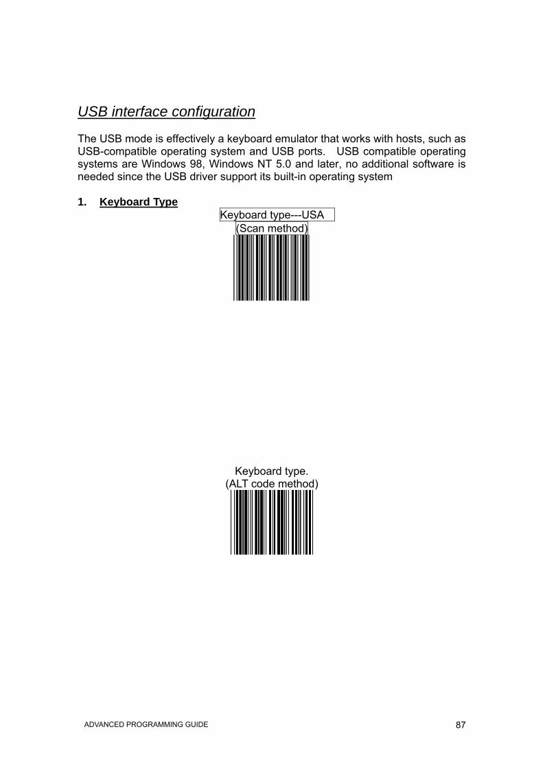
USB interface configuration The USB mode is effectively a keyboard emulator that works with hosts, such as USB-compatible operating system and USB ports. USB compatible operating systems are Windows 98, Windows NT 5.0 and later, no additional software is needed since the USB driver support its built-in operating system 1. Keyboard Type
Keyboard type---USA (Scan method)
Keyboard type. (ALT code method)

88 ADVANCED PROGRAMMING GUIDE
2. Message terminator for USB None
Enter

89 ADVANCED PROGRAMMING GUIDE
H tab

90 ADVANCED PROGRAMMING GUIDE
Wand emulation configuration
1. Emulation Speed Selection The data output speed can be set to befit the external decoder.
Wand emulation speed=Low (1ms narrow element width)
Wand emulation speed =medium (600 us narrow element width)

91 ADVANCED PROGRAMMING GUIDE
Wand emulation speed= high (300 us narrow element width)
Wand emulation speed ---- higher (100us narrow element width)

92 ADVANCED PROGRAMMING GUIDE
2. Emulation Data Output Selection The decoded data output logic level can be set to befit the external decoder.
Wand emulation data output black = high
Wand emulation data output black = low

93 ADVANCED PROGRAMMING GUIDE
Wand Data Transmitted as Scanning
Enable Wand output data format as Code 39

94 ADVANCED PROGRAMMING GUIDE
3. Emulation data idle state selection The level refer to wand emulation data signal when not in use
Idle=high
Idle=low

95 ADVANCED PROGRAMMING GUIDE
Data Editing

96 ADVANCED PROGRAMMING GUIDE
HEADER AND TRAILER The Header and Trailer allows you to append a header and/or a trailer to every message transmitted via the serial ports, USB or the keyboard port. There is no restriction in selecting header or trailer characters as far as the sum of the lengths of header and trailer is not greater than 10 digits. 1. Select either header or trailer you are going to program by scanning the
corresponding label 2. Scan the character(s) you want from the enclosed ASCII table to set as
header or trailer (be sure to enable full ASCII code 39 option before you start). 3. Read the “save setting to confirm” label to confirm your choice into memory.
Header (Preamble)

97 ADVANCED PROGRAMMING GUIDE
Trailer (Postamble)
Save setting to confirm

98 ADVANCED PROGRAMMING GUIDE
Truncate Header/Trailer Character This setting allows you to truncate a number of header or trailer for symbology. When you do, the specific character you select is deleted from the symbology you want. 1.) Scan the ”Enter/Exit programming mode” label. 2.) Select the ”Truncate header or truncate trailer” label. 3.) Scan two barcode value from the full ASCII code table(0~9). For example,
if 2 number of header that you want to clear, then scan ”0” and “2. 4,) Scan ”save setting to confirm” label 5,) Scan “Enter/Exit programming mode” label to end of configuration.

99 ADVANCED PROGRAMMING GUIDE
Truncate header character
Truncate trailer character

100 ADVANCED PROGRAMMING GUIDE
Add Code Length This option allows you to add the reading barcode numeric characters as header
Add code length as header enable (all barcode)
Add code length as header disable (all barcode)
101 ADVANCED PROGRAMMING GUIDE
Symbology Configuration
In this section, device can be programmed to recognize one or more barcode symbologies automatically. If the scanner is configured to support multiple barcode symbologies, the scanner will discriminate different symbologies automatically, however, to improve scanning performance, you should enable only those symbologies that will be in active use.

102 ADVANCED PROGRAMMING GUIDE
Reading code selection
Code 39 enable
Code 39 disable

103 ADVANCED PROGRAMMING GUIDE
Codabar enable
Codabar disable

104 ADVANCED PROGRAMMING GUIDE
UPC/EAN/JAN enable
UPC/EAN/JAN disable (only can’t transmitted but can decode)

105 ADVANCED PROGRAMMING GUIDE
ITF 2 of 5 enable
ITF 2 of 5 disable

106 ADVANCED PROGRAMMING GUIDE
Chinese postcode enable
Chinese postcode disable

107 ADVANCED PROGRAMMING GUIDE
Code 128 enable
Code 128 disable

108 ADVANCED PROGRAMMING GUIDE
Code 93 enable
Code 93 disable

109 ADVANCED PROGRAMMING GUIDE
EAN-128 enable
EAN-128 disable

110 ADVANCED PROGRAMMING GUIDE
EAN convert to ISSN/ISBN
EAN convert to ISSN/ISBN disable

111 ADVANCED PROGRAMMING GUIDE
Code 32 enable
Code 32 disable

112 ADVANCED PROGRAMMING GUIDE
MSI enable
MSI disable

113 ADVANCED PROGRAMMING GUIDE
UPC/EAN Parameters setting In this section, device can be programmed to recognize some or all derivatives of UPC/EAN. These derivatives are UPC-A, UPC-E, EAN-8, and EAN-13. Either 2 of 5 addendum digits are supported addendum digits are those additional digits after normal stop character. The programming menu for UPC/EAN/JAN also provides several options to govern the transmission of scanned data. *UPC/EAN expansion *Check digit transmission *Data redundant check *Addendum seek timeout *Addendum left/right margin adjust
1. Format
UPC/EAN/JAN all enable

114 ADVANCED PROGRAMMING GUIDE
EAN-8 or EAN-13 enable
UPC-A and EAN-13 Enable

115 ADVANCED PROGRAMMING GUIDE
UPC-A and UPC-E Enable
UPC-A enable

116 ADVANCED PROGRAMMING GUIDE
UPC-E enable
EAN-13 enable

117 ADVANCED PROGRAMMING GUIDE
EAN-8 enable

118 ADVANCED PROGRAMMING GUIDE
2. Force UPC-E to UPC-A format
Force UPC-E to UPC-A format enable
Force UPC-E to UPC-A format disable

119 ADVANCED PROGRAMMING GUIDE
3. Force UPC-A to EAN-13 format
Force UPC-A to EAN-13 format enable
Force UPC-A to EAN-13 format disable

120 ADVANCED PROGRAMMING GUIDE
4. Force EAN-8 to EAN-13 format
Force EAN-8 to EAN-13 format disable
Force EAN-8 to EAN-13 format enable

121 ADVANCED PROGRAMMING GUIDE
EAN-13 first “0” can transmitted
EAN-13 first “0” can’t transmitted
122 ADVANCED PROGRAMMING GUIDE
5. Transmit UPC-A check digit
Transmit UPC-A check digit enable
Transmit UPC-A check digit disable

123 ADVANCED PROGRAMMING GUIDE
6. Transmit UPC-E leading character
Transmit UPC-E leading character enable
Transmit UPC-E leading character disable
124 ADVANCED PROGRAMMING GUIDE
7. Transmit UPC-E check digit
Transmit UPC-E check digit enable
Transmit UPC-E check digit disable
125 ADVANCED PROGRAMMING GUIDE
8. Transmit EAN-8 check digit
Transmit EAN-8 check digit enable
Transmit EAN-8 check digit disable
126 ADVANCED PROGRAMMING GUIDE
9. Transmit EAN-13 check digit
Transmit EAN-13 check digit enable
Transmit EAN-13 check digit disable

127 ADVANCED PROGRAMMING GUIDE
10. Transmit UPC-A leading character
Transmit UPC-A leading character enable
Transmit UPC-a leading character disable

128 ADVANCED PROGRAMMING GUIDE
11. Addendum
UPC/EAN add on off
Add on 5 only

129 ADVANCED PROGRAMMING GUIDE
Add on 2 only
Add on 2 or 5
130 ADVANCED PROGRAMMING GUIDE
12. Add on format
Add on format with separator
Add on format without separator

131 ADVANCED PROGRAMMING GUIDE
EAN/UPC +Add on (none mandatory)
EAN/UPC + Add on(mandatory)

132 ADVANCED PROGRAMMING GUIDE
EAN/UPC + add on mandatory for 378/379 French Supplement requirement not sent for other
EAN/UPC +add on mandatory for 978/977 book land Supplement requirements
Not sent for other

133 ADVANCED PROGRAMMING GUIDE
EAN/UPC + addon mandatory for 434/439
German Supplement requirement Not sent for other
EAN/UPC + add on mandatory for 419/414 Euro amounts Supplement requirement
not sent for other
134 ADVANCED PROGRAMMING GUIDE
EAN/UPC + add on mandatory for 378/379
French Supplement requirement optionally for other
EAN/UPC + add on mandatory for 978/977 Book land Supplement requirement
optionally for other

135 ADVANCED PROGRAMMING GUIDE
EAN/UPC + add on mandatory for 434/439
German Supplement requirement optionally for other
EAN/UPC + add on mandatory for 419/414 Euro amounts Supplement requirement
optionally for other

136 ADVANCED PROGRAMMING GUIDE
EAN/UPC + add on mandatory for 491 Japanese (bookland) Supplement requirement optionally for other
EAN/UPC + add on mandatory for 491 Japanese (bookland) Supplement
requirement Not sent for other

137 ADVANCED PROGRAMMING GUIDE
Double code not allowed
Double code mandatory for 978/192

138 ADVANCED PROGRAMMING GUIDE
Double code format without separator
Double code format with separator

139 ADVANCED PROGRAMMING GUIDE
Double code format with free (one character)
140 ADVANCED PROGRAMMING GUIDE
13. Data Redundant Check In this section, user can set decoder data redundant check, before it is accepted as a good read. A higher data redundant check read setting offers more assurance that a barcode has been read correctly, while a lower setting allows faster scanning performance.
UPC-A Data Redundant Check
UPC-A data redundant check = 0
UPC-A data redundant check = 1

141 ADVANCED PROGRAMMING GUIDE
UPC-A data redundant check = 2
UPC-A data redundant check = 3

142 ADVANCED PROGRAMMING GUIDE
UPC-E Data Redundant Check
UPC-E data redundant check = 0
UPC-E data redundant check = 1

143 ADVANCED PROGRAMMING GUIDE
UPC-E data redundant check = 2
UPC-E data redundant check = 3

144 ADVANCED PROGRAMMING GUIDE
EAN-13 Data Redundant Check
EAN-13 data redundant check = 0
EAN- 13 data redundant check = 1

145 ADVANCED PROGRAMMING GUIDE
EAN-13 data redundant check = 2
EAN-13 data redundant check = 3

146 ADVANCED PROGRAMMING GUIDE
EAN-8 Data Redundant Check
EAN-8 data redundant check = 0
EAN-8 data redundant check = 1

147 ADVANCED PROGRAMMING GUIDE
EAN-8 data redundant check =2
EAN-8 data redundant check = 3
148 ADVANCED PROGRAMMING GUIDE
2 digit addendum data redundant check
2 digit addendum data redundant check = 0
2 digit addendum data redundant check = 1
149 ADVANCED PROGRAMMING GUIDE
2 digit addendum data redundant check = 2
2 digit addendum data redundant check = 3

150 ADVANCED PROGRAMMING GUIDE
5 digit addendum data redundant check
5 digit addendum data redundant check = 0
5 digit addendum data redundant check = 1

151 ADVANCED PROGRAMMING GUIDE
5 digit addendum data redundant check =2
5 digit addendum data redundant check = 3

152 ADVANCED PROGRAMMING GUIDE
Addendum seek timeout
Addendum seek timeout =6
Addendum seek timeout=7

153 ADVANCED PROGRAMMING GUIDE
Addendum seek timeout=8
Addendum seek timeout=9

154 ADVANCED PROGRAMMING GUIDE
Addendum seek timeout=10
155 ADVANCED PROGRAMMING GUIDE
Code 39 parameters setting The scanner can program to support the standard code 39 or Full ASCII code 39. In addition, it is user’s option to transmit or not to transmit the start and stop characters. You can also enable or disable the check digit feature. If the check digit feature is enabled, you have the further option to decide whether the check digit is transmitted or not.
Character Set
Standard code 39
FULL ASCII code 39

156 ADVANCED PROGRAMMING GUIDE
Start/Stop Character Transmission
Code 39 start/stop character transmission
Code 39 start/stop character without transmission
157 ADVANCED PROGRAMMING GUIDE
Check Digit
Code 39 check digit calculate and transmit
Code 39 check digit calculate but without transmit

158 ADVANCED PROGRAMMING GUIDE
No check character
159 ADVANCED PROGRAMMING GUIDE
1. Code 39 reading length setting The default code 39 length is 3 ~32 character. It can be set at minimum 1 digit and maximum 62 digits.
CODE LENGTH SETTING FLOW
Code 39 maximum length setting
Programming Minimum or Maximum label
Scan two number label from Code39 FULL ASCII table.
Example:4 character length, scan “0”,”4”
Scan “Save setting to confirm” label to confirm your choice into
memory.

160 ADVANCED PROGRAMMING GUIDE
Code 39 minimum length setting
Save setting to confirm
161 ADVANCED PROGRAMMING GUIDE
Concatenation
Code 39 concatenation enable
Code 39 concatenation disable

162 ADVANCED PROGRAMMING GUIDE
Code 32 “A” Character Transmit
Code 32 (Italian pharmacy) transmit “A” character
Code 32(Italian pharmacy)without transmit “A” character

163 ADVANCED PROGRAMMING GUIDE
2. Data Redundant Check In this section, users can use labels to set decoder data redundant check, before it is accepted as a good read. A higher data redundant check read setting offers more assurance that a barcode has been read correctly, while a lower setting allows faster scanning performance.
Code 39 data redundant check = 0
Code 39 data redundant check = 1

164 ADVANCED PROGRAMMING GUIDE
Code 39 data redundant check = 2
Code 39 data redundant check = 3
165 ADVANCED PROGRAMMING GUIDE
CODABAR Parameters Setting In this section, there are varies settings for Codabar symbology, including: • Check character verification or transmission • CODABAR concatenation • Data redundant check • Start/Stop Characters • Min./Max. length setting
1. Format
Codabar start/stop character transmission ----none
Codabar start/stop character transmission ---- A,B,C,D
166 ADVANCED PROGRAMMING GUIDE
Codabar start/stop character transmission ---- DC1~DC4
Codabar start/stop character transmission ---- a/t,b/n,c/*,d/e
167 ADVANCED PROGRAMMING GUIDE
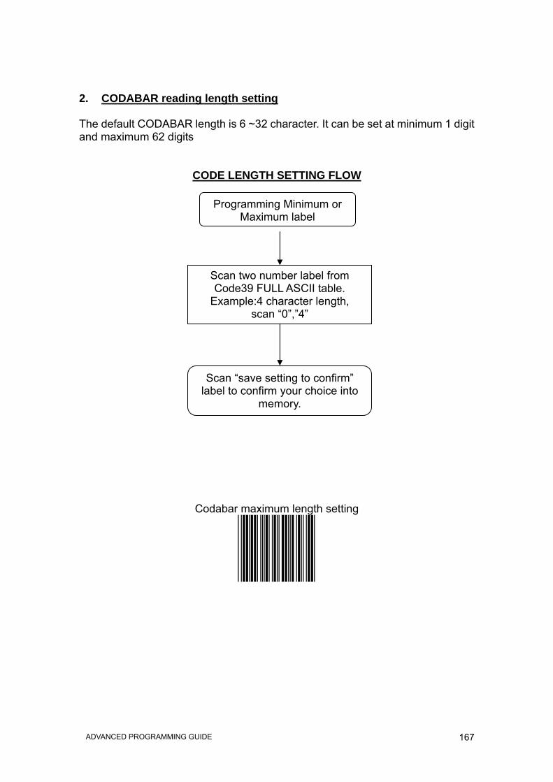
2. CODABAR reading length setting The default CODABAR length is 6 ~32 character. It can be set at minimum 1 digit and maximum 62 digits
CODE LENGTH SETTING FLOW
Codabar maximum length setting
Programming Minimum or Maximum label
Scan two number label from Code39 FULL ASCII table.
Example:4 character length, scan “0”,”4”
Scan “save setting to confirm” label to confirm your choice into
memory.

168 ADVANCED PROGRAMMING GUIDE
Codabar minimum length setting
Save setting to confirm
169 ADVANCED PROGRAMMING GUIDE
3. Concatenation
Codabar concatenation disable
Codabar concatenation enable
170 ADVANCED PROGRAMMING GUIDE
4. Check digit
No check character
Check digits calculate but not transmit

171 ADVANCED PROGRAMMING GUIDE
Check digit calculate and transmit

172 ADVANCED PROGRAMMING GUIDE
5. Data Redundant Check In this section, users can set decoder data redundant check, before it is accepted as a good read. A higher data redundant check read setting offers more assurance that a bar code has been read correctly, while a lower setting allows faster scanning performance.
Codabar data redundant check = 0
Codabar data redundant check = 1

173 ADVANCED PROGRAMMING GUIDE
Codabar data redundant check = 2
Codabar data redundant check = 3
174 ADVANCED PROGRAMMING GUIDE
Code 128 Parameters Setting In this section, there are varies setting for Code 128 symbology, including: • Check character verification or transmission • FNC2 concatenation • Data redundant check • FNC1 transmission for EAN-128 • Min./Max. length setting
1. Check Digit
No check character

175 ADVANCED PROGRAMMING GUIDE
Calculate but not transmit
Calculate and transmit
176 ADVANCED PROGRAMMING GUIDE
2. Code 128 FNC2 concatenation This function permits the temporary storage of a code in the decoder, if this code starts with FNC 2 character. The message buffered will be concatenated and transmitted with the next code having no FNC 2 character
Code 128 FNC2 concatenation enable
Code 128 FNC2 concatenation disable
177 ADVANCED PROGRAMMING GUIDE
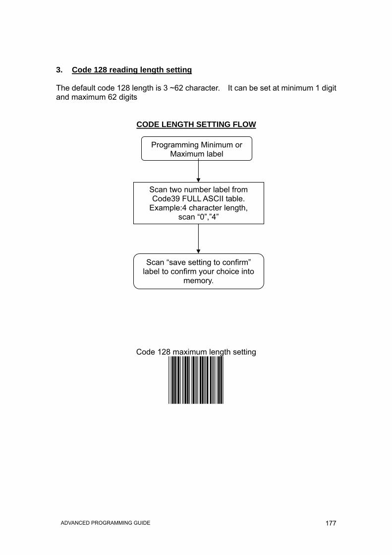
3. Code 128 reading length setting The default code 128 length is 3 ~62 character. It can be set at minimum 1 digit and maximum 62 digits
CODE LENGTH SETTING FLOW
Code 128 maximum length setting
Programming Minimum or Maximum label
Scan two number label from Code39 FULL ASCII table.
Example:4 character length, scan “0”,”4”
Scan “save setting to confirm” label to confirm your choice into
memory.

178 ADVANCED PROGRAMMING GUIDE
Code 128 minimum length setting
Save setting to confirm

179 ADVANCED PROGRAMMING GUIDE
4. EAN-128 FNC1 CHARACTER
EAN-128 FNC1 Character transmitted
EAN-128 FNC1 not character transmitted
180 ADVANCED PROGRAMMING GUIDE
5. Data Redundant Check In this section, users can set decoder data redundant check, before it is accepted as a good read. A higher data redundant check read setting offers more assurance that a bar code has been read correctly, while a lower setting allows faster scanning performance
Code 128 data redundant check = 0
Code 128 data redundant check = 1

181 ADVANCED PROGRAMMING GUIDE
Code 128 data redundant check = 2
Code 128 data redundant check = 3

182 ADVANCED PROGRAMMING GUIDE
ITF 2 of 5 Parameters Setting In this section, there are varies ITF 2 of 5 symbology including: • Check character verification or transmission • Data redundant check • Two fixed length setting • Min./Max. length setting
1. Check Digit
ITF 2 of 5 no check character
183 ADVANCED PROGRAMMING GUIDE
ITF 2 of 5 check digit calculate and transmit
ITF 2 of 5 check digit calculate but without transmit
184 ADVANCED PROGRAMMING GUIDE
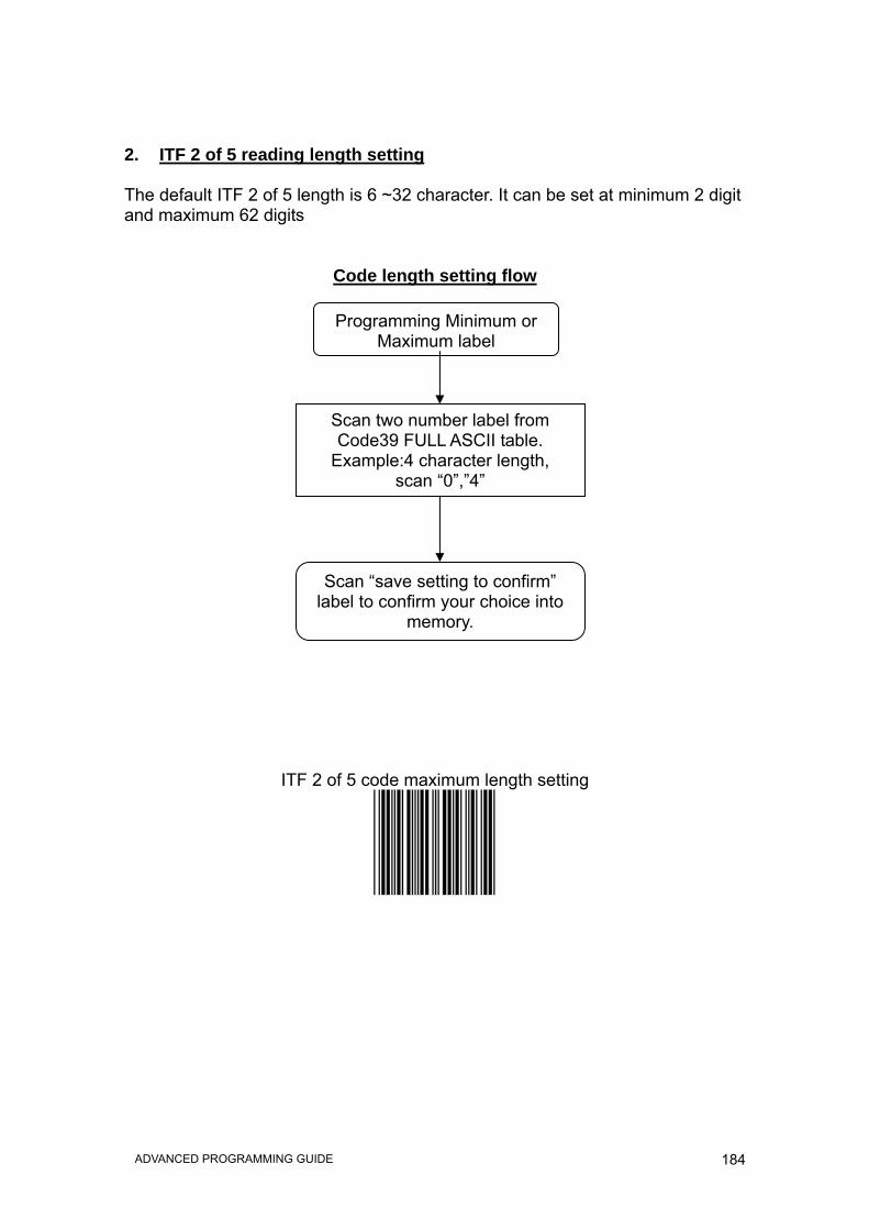
2. ITF 2 of 5 reading length setting The default ITF 2 of 5 length is 6 ~32 character. It can be set at minimum 2 digit and maximum 62 digits
Code length setting flow
ITF 2 of 5 code maximum length setting
Programming Minimum or Maximum label
Scan two number label from Code39 FULL ASCII table.
Example:4 character length, scan “0”,”4”
Scan “save setting to confirm” label to confirm your choice into
memory.

185 ADVANCED PROGRAMMING GUIDE
ITF 2 of 5 code minimum length setting
Save setting to confirm

186 ADVANCED PROGRAMMING GUIDE
ITF 2 of 5 one fixed length setting
ITF 2 of 5 two fixed length setting

187 ADVANCED PROGRAMMING GUIDE
3. Data Redundant Check In this section, users can set decoder data redundant check, before it is accepted as a good read. A higher data redundant check read setting offers more assurance that a bar code has been read correctly, while a lower setting allows faster scanning performance
ITF 25 data redundant check =0
ITF 25 data redundant check = 1

188 ADVANCED PROGRAMMING GUIDE
ITF 25 data redundant check = 2
ITF 25 data redundant check = 3
189 ADVANCED PROGRAMMING GUIDE
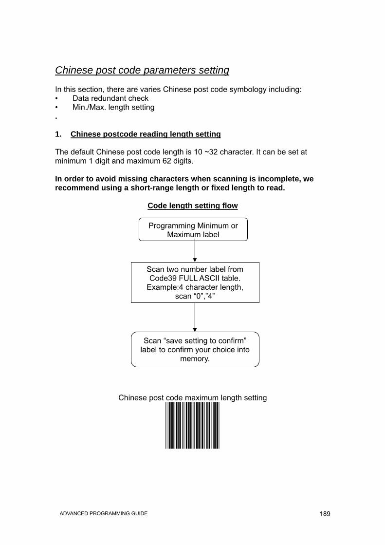
Chinese post code parameters setting In this section, there are varies Chinese post code symbology including: • Data redundant check • Min./Max. length setting .
1. Chinese postcode reading length setting The default Chinese post code length is 10 ~32 character. It can be set at minimum 1 digit and maximum 62 digits. In order to avoid missing characters when scanning is incomplete, we recommend using a short-range length or fixed length to read.
Code length setting flow
Chinese post code maximum length setting
Programming Minimum or Maximum label
Scan two number label from Code39 FULL ASCII table.
Example:4 character length, scan “0”,”4”
Scan “save setting to confirm” label to confirm your choice into
memory.

190 ADVANCED PROGRAMMING GUIDE
Chinese post code minimum length setting
Save setting to confirm

191 ADVANCED PROGRAMMING GUIDE
2. Data Redundant Check
The option allows you to set decoder data redundant check, before it is accepted as a good read. A higher data redundant check read setting offers more assurance that a bar code has been read correctly, while a lower setting allows faster scanning performance
Chinese post code data redundant check = 0
Chinese post code data redundant check = 1

192 ADVANCED PROGRAMMING GUIDE
Chinese post code data redundant check = 2
Chinese post code data redundant check = 3
193 ADVANCED PROGRAMMING GUIDE
MSI/PLESSY code Parameters Setting In this section, there are varies set up for Chinese post code symbology, including: • Check character verification or transmission • Data redundant check • Min./Max. length setting
1. Double Check Digit
MSI/PLESSY double check digit calculate but not transmit
MSI/PLESSY double check digit without calculate and transmit

194 ADVANCED PROGRAMMING GUIDE
MSI/PLESSY double check digit calculate but only first digit transmit
MSI/PLESSY double check digit calculate and both transmit

195 ADVANCED PROGRAMMING GUIDE
2. Single Check Digit
MSI/PLESSY single check digit calculate but without transmit
MSI/Plessy single check digit calculate and transmit

196 ADVANCED PROGRAMMING GUIDE
3. MSI/PLESSY code reading length setting The default MSI/PLESSY code length is 6~32 character. It can be set at minimum 1 digit and maximum 62 digits
Code Length Setting Flow
MSI/PLESSY maximum length setting
Programming Minimum or Maximum label
Scan two number label from Code39 FULL ASCII table.
Example:4 character length, scan “0”,”4”
Scan “save setting to confirm” label to confirm your choice into
memory.

197 ADVANCED PROGRAMMING GUIDE
MSI/PLESSY minimum length setting
Save setting to confirm
198 ADVANCED PROGRAMMING GUIDE
4. Data Redundant Check The option allows you to set decoder data redundant check, before it is accepted as a good read. A higher data redundant check read setting offers more assurance that a barcode has been read correctly, while a lower setting allows faster scanning performance
MSI data redundant check = 0
MSI data redundant check = 1
199 ADVANCED PROGRAMMING GUIDE
MSI data redundant check = 2
MSI data redundant check = 3
200 ADVANCED PROGRAMMING GUIDE
Code 93 Parameters Setting In this section, there are varies set up for Code 93 symbology, including: • Check character verification or transmission • Data redundant check • Min./Max. length setting
1. Check Digit
Code 93 check digit calculate but without transmit
201 ADVANCED PROGRAMMING GUIDE
Code 93 check digit not calculate and without transmit
Code 93 check digit calculate and transmit
202 ADVANCED PROGRAMMING GUIDE
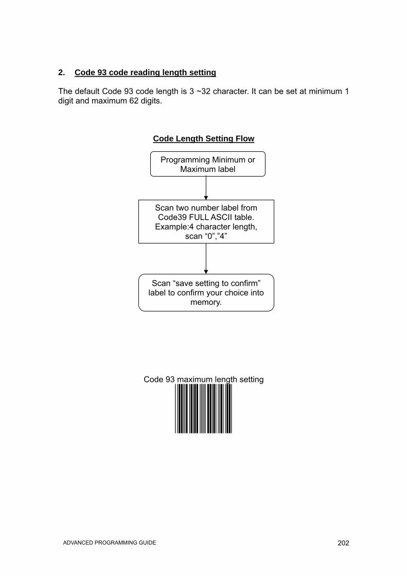
2. Code 93 code reading length setting The default Code 93 code length is 3 ~32 character. It can be set at minimum 1 digit and maximum 62 digits.
Code Length Setting Flow
Code 93 maximum length setting
Programming Minimum or Maximum label
Scan two number label from Code39 FULL ASCII table.
Example:4 character length, scan “0”,”4”
Scan “save setting to confirm” label to confirm your choice into
memory.

203 ADVANCED PROGRAMMING GUIDE
Code 93 minimum length setting
Save setting to confirm
204 ADVANCED PROGRAMMING GUIDE
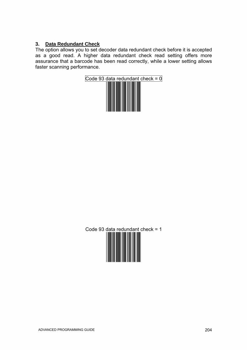
3. Data Redundant Check The option allows you to set decoder data redundant check before it is accepted as a good read. A higher data redundant check read setting offers more assurance that a barcode has been read correctly, while a lower setting allows faster scanning performance.
Code 93 data redundant check = 0
Code 93 data redundant check = 1

205 ADVANCED PROGRAMMING GUIDE
Code 93 data redundant check = 2
Code 93 data redundant check = 3

206 ADVANCED PROGRAMMING GUIDE
Full ASCII Code Table

207 ADVANCED PROGRAMMING GUIDE
Full ASCII --- NUL
Full ASCII ---- SOH (Function Key---Ins)

208 ADVANCED PROGRAMMING GUIDE
Full ASCII ----STX
(Function Key---Del)
Full ASCII ---- ETX (Function Key---Home)

209 ADVANCED PROGRAMMING GUIDE
Full ASCII ---- EOT
(Function Key---End)
Full ASCII ---- ENQ (Function Key---Up arrow)
210 ADVANCED PROGRAMMING GUIDE
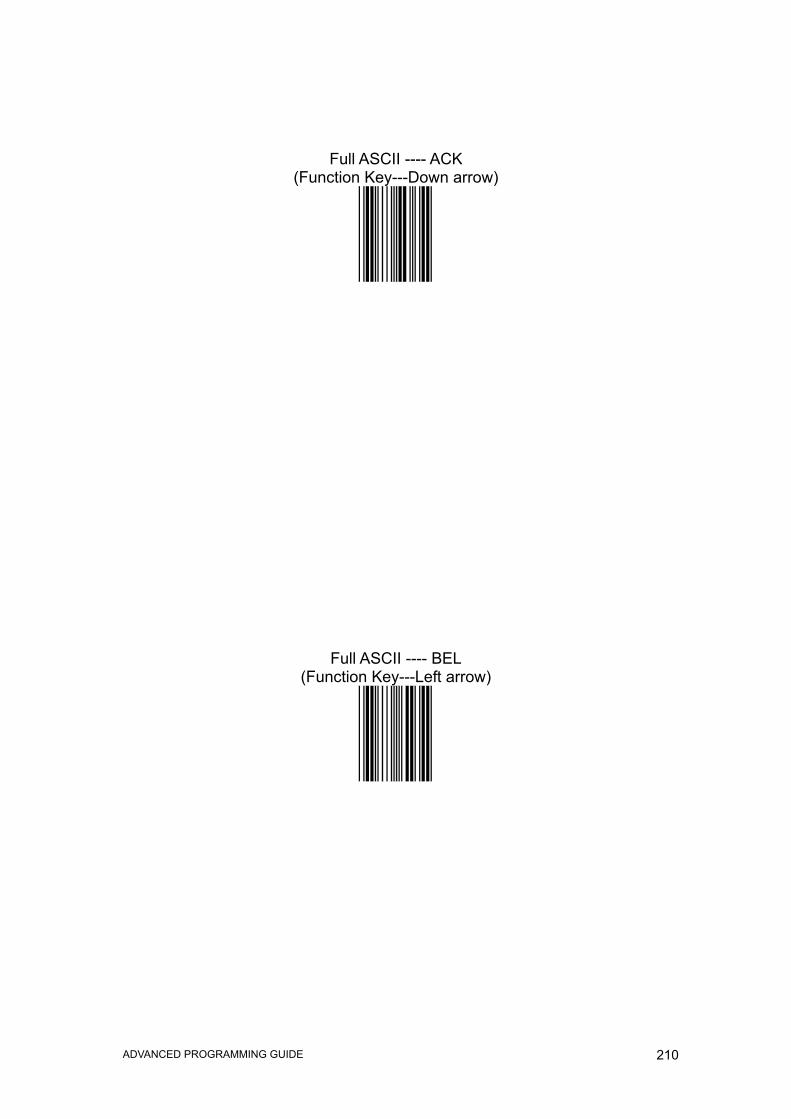
Full ASCII ---- ACK
(Function Key---Down arrow)
Full ASCII ---- BEL (Function Key---Left arrow)

211 ADVANCED PROGRAMMING GUIDE
Full ASCII ---- BS
(Function Key---Backspace)
Full ASCII ---- HT (Function Key---Tab)

212 ADVANCED PROGRAMMING GUIDE
Full ASCII ---- LF
(Function Key---Enter(num))
Full ASCII ---- VT (Function Key---Right arrow)

213 ADVANCED PROGRAMMING GUIDE
Full ASCII ---- FF
(Function Key---PgUp)
Full ASCII ---- CR (Function Key---Enter(alphabet))

214 ADVANCED PROGRAMMING GUIDE
Full ASCII ---- SO
(Function Key---PgDn)
Full ASCII ---- SI (Function Key---Shift)

215 ADVANCED PROGRAMMING GUIDE
Full ASCII ---- DLE
(Function Key---5(num))
Full ASCII ---- DC1 (Function Key---F1)

216 ADVANCED PROGRAMMING GUIDE
Full ASCII ---- DC2 (Function Key---F2)
Full ASCII ---- DC3 (Function Key---F3)

217 ADVANCED PROGRAMMING GUIDE
Full ASCII ---- DC4 (Function Key---F4)
Full ASCII ---- NAK (Function Key---F5)

218 ADVANCED PROGRAMMING GUIDE
Full ASCII ---- SYN (Function Key---F6)
Full ASCII ---- ETB (Function Key---F7)

219 ADVANCED PROGRAMMING GUIDE
Full ASCII ---- CAN (Function Key---F8)
Full ASCII ---- EN (Function Key---F9)

220 ADVANCED PROGRAMMING GUIDE
Full ASCII ---- SUB
(Function Key---F10)
Full ASCII ---- ESC (Function Key---F11)

221 ADVANCED PROGRAMMING GUIDE
Full ASCII ---- FS
(Function Key---F12)
Full ASCII ---- GS (Function Key---ESC)

222 ADVANCED PROGRAMMING GUIDE
Full ASCII ---- RS
(Function Key---Ctl(L))
Full ASCII ---- US (Function Key---Alt(L))

223 ADVANCED PROGRAMMING GUIDE
Full ASCII ---- SP
Full ASCII ---- !

224 ADVANCED PROGRAMMING GUIDE
Full ASCII ---- “
Full ASCII ---- #

225 ADVANCED PROGRAMMING GUIDE
Full ASCII ---- $
Full ASCII ---- %

226 ADVANCED PROGRAMMING GUIDE
Full ASCII ---- &
Full ASCII ---- ‘

227 ADVANCED PROGRAMMING GUIDE
Full ASCII ---- (
Full ASCII ---- )

228 ADVANCED PROGRAMMING GUIDE
Full ASCII ---- *
Full ASCII ---- +

229 ADVANCED PROGRAMMING GUIDE
Full ASCII ---- ,
Full ASCII ---- -

230 ADVANCED PROGRAMMING GUIDE
Full ASCII ---- .
Full ASCII ---- /

231 ADVANCED PROGRAMMING GUIDE
Full ASCII ---- 0
Full ASCII ---- 1

232 ADVANCED PROGRAMMING GUIDE
Full ASCII ---- 2
Full ASCII ---- 3

233 ADVANCED PROGRAMMING GUIDE
Full ASCII ---- 4
Full ASCII ---- 5

234 ADVANCED PROGRAMMING GUIDE
Full ASCII ---- 6
Full ASCII ---- 7

235 ADVANCED PROGRAMMING GUIDE
Full ASCII ---- 8
Full ASCII ----9

236 ADVANCED PROGRAMMING GUIDE
Full ASCII ---- :
Full ASCII ---- ;

237 ADVANCED PROGRAMMING GUIDE
Full ASCII ---- <
Full ASCII ---- =

238 ADVANCED PROGRAMMING GUIDE
Full ASCII ---- >
Full ASCII ---- ?

239 ADVANCED PROGRAMMING GUIDE
Full ASCII ---- @
Full ASCII ---- A

240 ADVANCED PROGRAMMING GUIDE
Full ASCII ---- B
Full ASCII ---- C

241 ADVANCED PROGRAMMING GUIDE
Full ASCII ---- D
Full ASCII ---- E

242 ADVANCED PROGRAMMING GUIDE
Full ASCII ---- F
Full ASCII ---- G

243 ADVANCED PROGRAMMING GUIDE
Full ASCII ---- H
Full ASCII ---- I

244 ADVANCED PROGRAMMING GUIDE
Full ASCII ---- J
Full ASCII ---- K

245 ADVANCED PROGRAMMING GUIDE
Full ASCII ---- L
Full ASCII ---- M

246 ADVANCED PROGRAMMING GUIDE
Full ASCII ---- N
Full ASCII ---- O

247 ADVANCED PROGRAMMING GUIDE
Full ASCII ---- P
Full ASCII ---- Q

248 ADVANCED PROGRAMMING GUIDE
Full ASCII ---- R
Full ASCII ---- S

249 ADVANCED PROGRAMMING GUIDE
Full ASCII ---- T
Full ASCII ---- U

250 ADVANCED PROGRAMMING GUIDE
Full ASCII ---- V
Full ASCII ---- W

251 ADVANCED PROGRAMMING GUIDE
Full ASCII ---- X
Full ASCII ---- Y

252 ADVANCED PROGRAMMING GUIDE
Full ASCII ---- Z
Full ASCII ---- [

253 ADVANCED PROGRAMMING GUIDE
Full ASCII ---- \
Full ASCII ---- ]

254 ADVANCED PROGRAMMING GUIDE
Full ASCII ---- ^
Full ASCII ---- _

255 ADVANCED PROGRAMMING GUIDE
Full ASCII ---- `
Full ASCII ---- a

256 ADVANCED PROGRAMMING GUIDE
Full ASCII ---- b
Full ASCII ---- c

257 ADVANCED PROGRAMMING GUIDE
Full ASCII ---- d
Full ASCII ---- e

258 ADVANCED PROGRAMMING GUIDE
Full ASCII ---- f
Full ASCII ---- g

259 ADVANCED PROGRAMMING GUIDE
Full ASCII ---- h
Full ASCII ---- i

260 ADVANCED PROGRAMMING GUIDE
Full ASCII ---- j
Full ASCII ---- k

261 ADVANCED PROGRAMMING GUIDE
Full ASCII ---- l
Full ASCII ---- m

262 ADVANCED PROGRAMMING GUIDE
Full ASCII ---- n
Full ASCII ---- o

263 ADVANCED PROGRAMMING GUIDE
Full ASCII ---- p
Full ASCII ---- q

264 ADVANCED PROGRAMMING GUIDE
Full ASCII ---- r
Full ASCII ---- s

265 ADVANCED PROGRAMMING GUIDE
Full ASCII ---- t
Full ASCII ---- u

266 ADVANCED PROGRAMMING GUIDE
Full ASCII ---- v
Full ASCII ---- w

267 ADVANCED PROGRAMMING GUIDE
Full ASCII ---- x
Full ASCII ---- y

268 ADVANCED PROGRAMMING GUIDE
Full ASCII ---- z
Full ASCII ---- {

269 ADVANCED PROGRAMMING GUIDE
Full ASCII ---- |
Full ASCII ---- }

270 ADVANCED PROGRAMMING GUIDE
Full ASCII ---- ~
Full ASCII ---- DEL

271 ADVANCED PROGRAMMING GUIDE
APPENDIXES
272 ADVANCED PROGRAMMING GUIDE
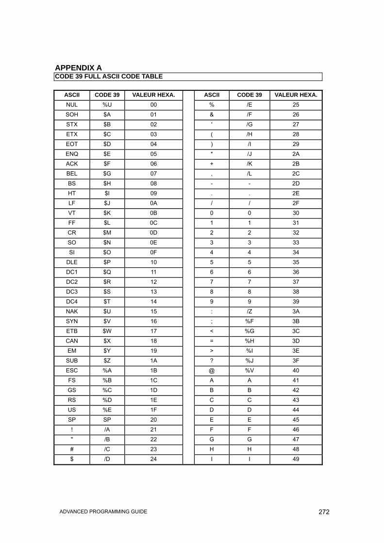
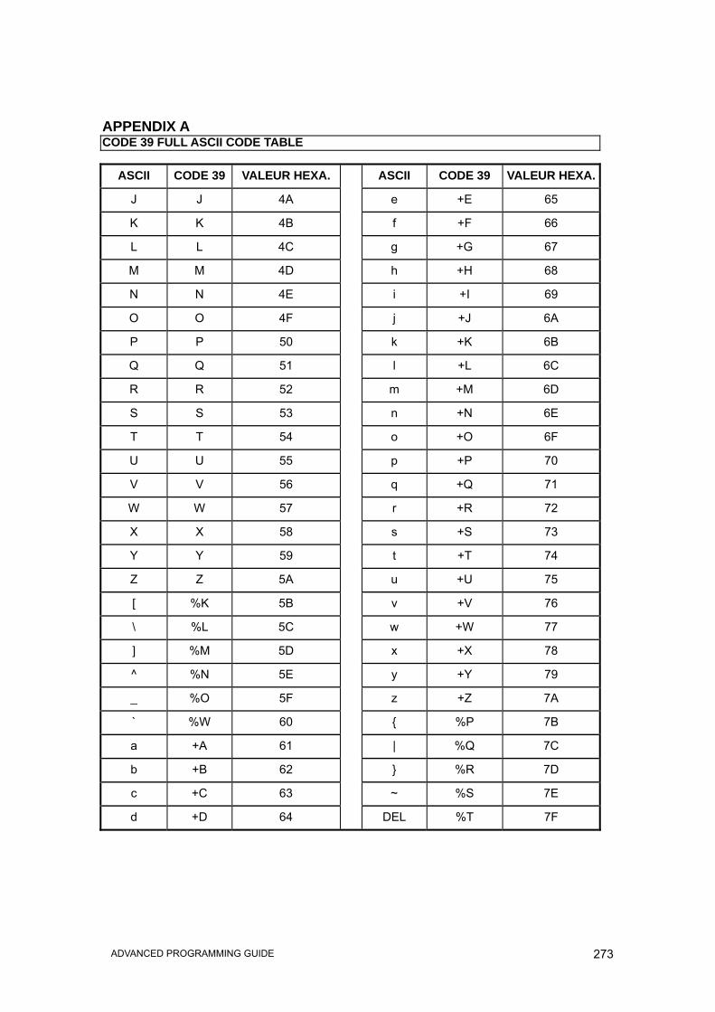
APPENDIX A CODE 39 FULL ASCII CODE TABLE
ASCII CODE 39 VALEUR HEXA. ASCII CODE 39 VALEUR HEXA.NUL %U 00 % /E 25
SOH $A 01 & /F 26
STX $B 02 ' /G 27
ETX $C 03 ( /H 28
EOT $D 04 ) /I 29
ENQ $E 05 * /J 2A
ACK $F 06 + /K 2B
BEL $G 07 , /L 2C
BS $H 08 - - 2D
HT $I 09 . . 2E
LF $J 0A / / 2F
VT $K 0B 0 0 30
FF $L 0C 1 1 31
CR $M 0D 2 2 32
SO $N 0E 3 3 33
SI $O 0F 4 4 34
DLE $P 10 5 5 35
DC1 $Q 11 6 6 36
DC2 $R 12 7 7 37
DC3 $S 13 8 8 38
DC4 $T 14 9 9 39
NAK $U 15 : /Z 3A
SYN $V 16 ; %F 3B
ETB $W 17 < %G 3C
CAN $X 18 = %H 3D
EM $Y 19 > %I 3E
SUB $Z 1A ? %J 3F
ESC %A 1B @ %V 40
FS %B 1C A A 41
GS %C 1D B B 42
RS %D 1E C C 43
US %E 1F D D 44
SP SP 20 E E 45
! /A 21 F F 46
" /B 22 G G 47
# /C 23 H H 48
$ /D 24 I I 49
273 ADVANCED PROGRAMMING GUIDE
APPENDIX A CODE 39 FULL ASCII CODE TABLE
ASCII CODE 39 VALEUR HEXA. ASCII CODE 39 VALEUR HEXA.
J J 4A e +E 65
K K 4B f +F 66
L L 4C g +G 67
M M 4D h +H 68
N N 4E i +I 69
O O 4F j +J 6A
P P 50 k +K 6B
Q Q 51 l +L 6C
R R 52 m +M 6D
S S 53 n +N 6E
T T 54 o +O 6F
U U 55 p +P 70
V V 56 q +Q 71
W W 57 r +R 72
X X 58 s +S 73
Y Y 59 t +T 74
Z Z 5A u +U 75
[ %K 5B v +V 76
\ %L 5C w +W 77
] %M 5D x +X 78
^ %N 5E y +Y 79
_ %O 5F z +Z 7A
` %W 60 { %P 7B
a +A 61 | %Q 7C
b +B 62 } %R 7D
c +C 63 ~ %S 7E
d +D 64 DEL %T 7F
274 ADVANCED PROGRAMMING GUIDE
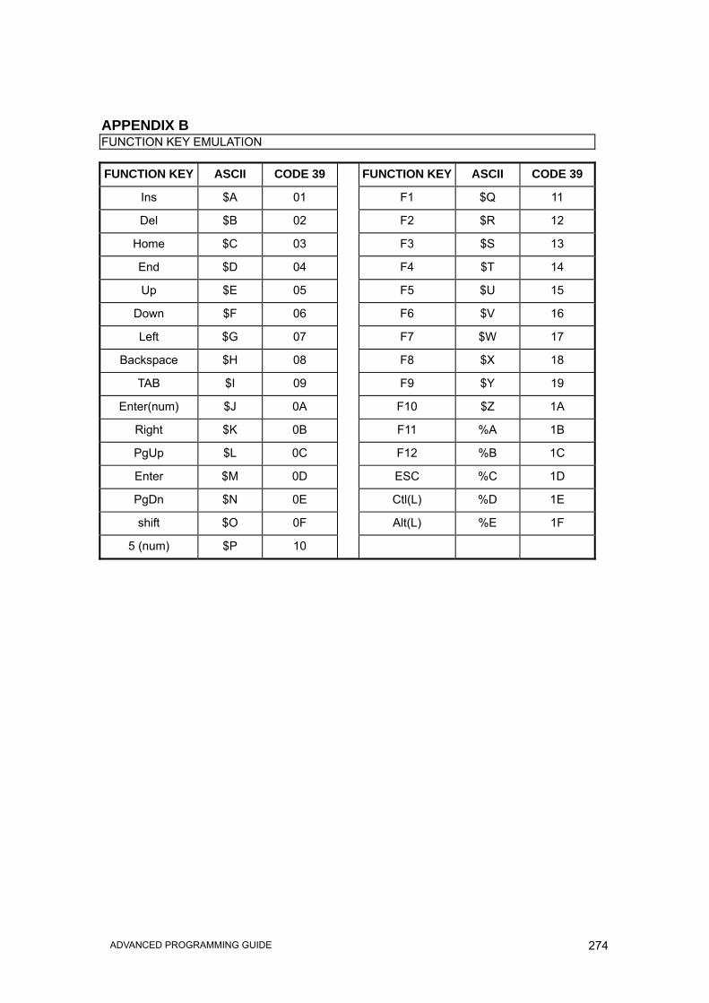
APPENDIX B FUNCTION KEY EMULATION
FUNCTION KEY ASCII CODE 39 FUNCTION KEY ASCII CODE 39
Ins $A 01 F1 $Q 11
Del $B 02 F2 $R 12
Home $C 03 F3 $S 13
End $D 04 F4 $T 14
Up $E 05 F5 $U 15
Down $F 06 F6 $V 16
Left $G 07 F7 $W 17
Backspace $H 08 F8 $X 18
TAB $I 09 F9 $Y 19
Enter(num) $J 0A F10 $Z 1A
Right $K 0B F11 %A 1B
PgUp $L 0C F12 %B 1C
Enter $M 0D ESC %C 1D
PgDn $N 0E Ctl(L) %D 1E
shift $O 0F Alt(L) %E 1F
5 (num) $P 10

275 ADVANCED PROGRAMMING GUIDE
Enter/Exit programming