enterprise campus network design...
TRANSCRIPT

1
Chapter 3
Enterprise Campus Network Design

Overview The network foundation hosting these technologies for
an emerging enterprise should be efficient, highly available, scalable, and manageable.
This module provides recommended designs for the campus network, and includes descriptions of various topologies, routing protocols, configuration guidelines, and other considerations relevant to the design of highly available and reliable campus networks.
2

High Availability in the Enterprise Campus
The hierarchical network model supports designing a highly available modular topology using scalable building blocks that allow the network to meet evolving business needs.
The modular design makes the network easy to scale, understand, and troubleshoot by promoting deterministic traffic patterns.
Objectives: 1. Describe the layers of the enterprise campus
architecture 2. Discuss high availability options in the enterprise
campus
3

Enterprise Campus Infrastructure Three layers: access layer, distribution layer, and core
layer. The access layer is the point of entry into the network
for end devices.
4
Note
Access Layer Aggregates end users and provides uplinks to the
distribution layer.
The access layer can be a feature-rich environment: High availability
Convergence: Supports inline power over Ethernet (PoE)
for IP telephony and wireless access points, allowing customers to converge voice onto their data network and providing roaming WLAN access for users
Security: Provides services for additional security against unauthorized access to the network.
5

Access Layer
Quality of Service (QoS): Allows prioritization of mission-critical network traffic using traffic classification and queuing as close to the ingress of the network as possible
IP multicast: Supports efficient network and bandwidth management using software features such as Internet Group Management Protocol (IGMP) snooping.
6

7
IGMP basics
NB: 255=225
Step 1

8
IGMP basics
NB: 255=225
Step 2

10
IGMP Versions IGMP v1
Membership query Membership report
IGMP v2 Membership query V2 Membership report (Fast Leave) Leave group V1 Membership report
IGMP v3 Membership query V3 Membership report (Explicit Host Tracking) V2 Leave group V2 Membership report V2 Leave group V1 Membership report

11
Definitions
IGMP Proxy Terminates LAN side IGMP Initiates IGMP on WAN side Port-based bridge group
IGMP Snooping
Layer 2 switch uses Layer 3 IP header for intelligent forwarding
No traffic is send on parts were no IGMP is required

Distribution Layer Aggregates nodes and uplinks from the access layer
and provides policy-based connectivity. Availability, load balancing, QoS and provisioning are
the important considerations at this layer.
12

Distribution Layer
The distribution layer is the place where routing and packet manipulation are performed and can be a routing boundary between the access and core layers.
To further improve routing protocol performance, the distribution layer summarizes routes from the access layer.
The distribution layer uses a combination of Layer 2 and multilayer switching to segment workgroups and isolate network problems, preventing them from impacting the core layer.
13

Core Layer
Provides scalability, high availability, and fast convergence to the network.
14

Core Layer
The core layer is the backbone and is the aggregation point the other layers and modules.
The core should be a high-speed, Layer 3 switching environment utilizing hardware-accelerated services.
The core devices must be able to implement scalable protocols technologies alternate paths load balancing
15

Is a Core Layer Needed? The core and distribution layer functions can be
combined at the distribution layer for a smaller campus.
16

Is a Core Layer Needed?
Without a core layer, the distribution layer switches will need to be fully meshed.
This design is difficult to scale, and increases the cabling requirements as new building distribution switch need full-mesh connectivity to all the distribution switches.
The routing complexity of a full mesh design increases as new neighbors are added. four additional links for full mesh connectivity to the first
module. require 8 additional links to support connections to all the
distribution switches, or a total of 12 links
17

Implement Optimal Redundancy High availability is concerned with minimizing link
and node failures and optimizing recovery times to minimize convergence and downtime.
Access switches should have redundant connections to redundant distribution switches.
18

Implement Optimal Redundancy
The core and distribution layers are built with redundant switches and fully meshed links to provide maximum redundancy and optimal convergence.
Access switches should have redundant connections to redundant distribution switches.
In a fully redundant topology, redundant supervisors with nonstop forwarding (NSF) and stateful switchover (SSO) may cause longer convergence times than single supervisors. NSF/SSO are designed to maintain link up/Layer 3 up state
during a convergence event.
19

Provide Alternate Paths
20

Avoid Single Points of Failure
Nonstop forwarding with stateful switchover (NSF/SSO) and redundant supervisors have the most impact in the campus in the access layer.
21

Cisco Solutions
NSF/SSO is a supervisor redundancy mechanism in Cisco IOS Software that allows extremely fast supervisor switchover at Layers 2 to 4.
22

NSF/SSO
SSO allows the standby Route Processor (RP) to takes control of the device after a hardware or software fault on the Active RP. SSO synchronizes startup configuration, startup variables, and
running configuration as well as dynamic runtime data including Layer 2 protocol state for trunks and ports, hardware Layer 2 and Layer 3 tables (MAC, FIB(forwarding information base), adjacency table) as well as ACL and QoS tables.
NSF is a Layer 3 function that works with SSO to minimize the amount of time a network is unavailable to its users following a switchover.
The main objective of NSF is to continue forwarding IP packets following a RP switchover.
23
Layer 2 Design Recommendations
24

Objectives
To develop designs to support Layer 2 high availability and optimum convergence. Describe how to support supporting tree
convergence in the enterprise campus Discuss how to harden Layer 2 for STP predictability Describe recommended practices for Layer 2 trunks Describe recommended practices for UDLD
(unidirectional link detection) configuration Describe recommended practices for EtherChannel
25

Spanning Tree
For the most deterministic and highly available network topology, the requirement to support Spanning Tree Protocol (STP) convergence.
There are several reasons you may need to implement STP: When a VLAN spans access layer switches in order to support
business applications. To protect against “user side” loops.
STP lets the network deterministically block interfaces and provide a loop-free topology in a network with redundant links.
To support data center application on a server farm.
26

Spanning Tree
Drawback: Not all physical links are used No load-sensitive dynamic routing Fail-over latency is high ( > 5 seconds)
27

28
Spanning Tree Topology
s1
N3 N5
N1 N8 N7
N6
N4
N2 s3 s4
s2

29
Spanning Tree Topology
s1
N3 N5
N1 N8 N7
N6
N4
N2 s3 s4
s2
Root
R D
D B

30
IEEE 802.1D: STP
A distributed spanning tree construction algorithm Bridge Protocol Data Unit (BPDU): root ID, cost (link
data rate), sender ID Port state: Root, Designated, Blocked and Disabled Port operating mode:
Blocked: receiving BPDU Listening: receiving/processing BPDU Learning: receiving/processing BPDU, and learning Forwarding: receiving/processing BPDU, learning, and
forwarding Slow convergence: 30 seconds
Everyone agrees on a common SPT Everyone knows that everyone agrees on a common SPT, and
turn a port from blocked to forwarding

STP (1)
The Spanning-Tree Protocol establishes a root node, called the root bridge STP constructs a topology that has one path for
reaching every network node
The resulting tree originates from the root bridge
Redundant links that are not part of the shortest path tree are blocked.
Data frames received on blocked links are dropped.
Because certain paths are blocked, a loop free topology is possible

STP (2) There are several varieties of STP:
STP is the original 802.1D version to provide a loop-free topology in a network with redundant links.
Common Spanning Tree (CST) assumes one spanning-tree instance for the entire bridged network, regardless of the number of VLANs.
Rapid STP (RSTP), or 802.1w, is an evolution of STP providing for faster convergence of STP.
32

33
Broadcast and Source Learning
Source learning: When receiving a packet, bind its source address with the port via which it comes in
Switch broadcasts a packet when its forwarding state does not exist
Example: N7 sends a packet to N3 N7 sends a broadcast-based ARP query for N3
Establishing forwarding state for N7 in the spanning tree
N3 responds with a unicast-based ARP response Establish forwarding state for N3 in the spanning
tree

34
Broadcast and Source Learning
s1
N3 N5
N1 N8 N7
N6
N4
N2 s3 s4
s2
Root
R D
D B

Spanning-Tree Operation When the network has stabilized, it has
converged and there is one spanning tree per network
For every switched network the following elements exist: One root bridge per network One root port per non root bridge One designated port per segment Unused, non-designated ports
Root ports and designated ports forward data traffic.
Non-designated ports discard data traffic These ports are called blocking or discarding ports

Selecting the Root Bridge The first decision that all switches in the
network make, is to identify the root bridge using the spanning-tree algorithm
the bridge with the smallest Bridge ID (BID) value will be the root bridge.
BPDUs are sent out with the Bridge ID (BID).
The BID consists of a bridge priority (that defaults to 32768) and the switch base MAC address
All switches send the BPDU
Default BPDUs are sent every two seconds

Selecting the Root Bridge Cont’d When a switch first starts up, it assumes it is
the root switch and sends “inferior” BPDUs. These BPDUs contain the bridge priority and switch
MAC address in both the root and sender BID
As a switch receives a BPDU with a lower root BID it replaces that in the subsequent BPDUs it sends out
A network administrator can influence the decision by setting the switch priority to a smaller value than the default (Using smaller BID) Should only be implemented when the traffic flow
on the network is well understood

Four Stages of Spanning-Tree Port States
•A port can also be in a disabled state which occurs when an administrator shuts down the port or the port fails.

Blocking State Ports can only receive BPDUs
Data frames are discarded and no addresses can be learned
It may take up to 20 seconds to change from this state
Listening State Switches determine if there are any other paths to the root
bridge
The path that is not the least cost path to the root bridge goes back to the blocked state
BPDUs are still processed.
User data is not being forwarded and MAC addresses are not being learned
The listening period is called the forward delay and lasts for 15 seconds
Four Stages of Spanning-Tree Port States

Learning State User data is not forwarded, but MAC addresses
are learned from any traffic that is seen The learning state lasts for 15 seconds and is also
called the forward delay BPDUs are still processed
Forwarding state User data is forwarded and MAC addresses
continue to be learned BPDUs are still processed
Disabled State (Fifth State) Can occur when an administrator shuts down the
port or the port fails
Four Stages of Spanning-Tree Port States

Spanning-Tree Recalculation A switched internetwork has converged when
all the switch and bridge ports are in either the forwarding or blocked state Forwarding ports send and receive data traffic and
BPDUs
Blocked ports will only receive BPDUs
When the network topology changes, switches and bridges recompute the Spanning Tree causing a disruption of user traffic.
Convergence on a new spanning-tree topology using the IEEE 802.1D standard can take up to 30 seconds
Bridge Protocol Data Units (BPDUs)
The Spanning-Tree Protocol requires network devices to exchange messages to help form a loop-free logical topology
These messages are called Bridge Protocol Data Units (BPDUs)
Links that will cause a loop are put into a blocking state
BPDUs continue to be received on blocked ports ensures that if an active path or device fails, a
new spanning tree can be calculated

Information Contained in BPDUs
BPDUs BPDUs help switches do the following:
Select a single switch that will act as the root of the spanning tree
Calculate the shortest path from itself to the root switch
Designate one of the switches as the closest one to the root, for each LAN segment. This bridge is called the “designated switch” The designated switch handles all communication from that
LAN towards the root bridge. Choose one of its ports as a root port (if it is a non-
root switch) This is the interface that gives the best path to root switch.
Select ports that are part of the spanning tree, called designated ports
Non-designated ports are blocked

Root Ports, Designated Ports, & Non-Designated Ports

Summary
The Configuration BPDU contains enough info. so that bridges can do the following:
1) Elect a single bridge to be Root Bridge 2) Calculate the distance of the shortest path from
themselves to the Root Bridge 3) Elect a Designated Bridge for each LAN segment,
which is the bridge in the LAN segment closest to the Root Bridge, to forward packets from that LAN segment toward the Root Bridge.
4) Choose the port, called the root port, that gives the best path from themselves to the Root Bridge.
5) Select ports to be included in the spanning tree. These include only root ports and designated ports.

CISCO STP Instructions
PortFast*: Causes a Layer 2 LAN interface configured as an access port to enter the forwarding state immediately, bypassing the listening and learning states. (從 Disable state 直接到 Forwarding state) Use PortFast only when connecting a single end
station to a Layer 2 access port.
UplinkFast: Provides three to five seconds convergence after a direct link failure and achieves load balancing between redundant Layer 2 links using uplink groups. (可以在有link故障的情況下改善 STP 的收斂時間)
47

CISCO STP Instructions
BackboneFast: Cuts convergence time by max_age for indirect failure. (是在某條沒有直接連到該交換器的link故障時, 用來加快收斂的速度) BackboneFast is initiated when a root port or blocked port on a
network device receives inferior BPDUs from its designated bridge.
LoopGuard*: LoopGuard helps prevent bridging loops that could occur because of a unidirectional link failure on a point-to-point link.
RootGuard*: Secures root on a specific switch by preventing external switches from becoming root.
BPDUGuard*: When enabled on a port, BPDU Guard shuts down a port that receives a BPDU.
48

Layer 2 Hardening
49

Layer 2 Hardening
Loop guard is implemented on the Layer 2 ports between distribution switches, and on the uplink ports from the access switches to the distribution switches.
Root guard is configured on the distribution switch ports facing the access switches.
UplinkFast is implemented on the uplink ports from the access switches to the distribution switches.
BPDU guard or root guard is configured on ports from the access switches to the end devices, as is PortFast.
50

Layer 3 Design Recommendations
51

Objectives
Describe recommendations for managing oversubscription and bandwidth
Discuss design tradeoffs for supporting link load balancing
Describe recommendations for routing protocol design Discuss recommendations for first hop redundancy
protocols
52

Oversubscription and Bandwidth
53

Oversubscription Ratio
Typical campus networks are designed with oversubscription.
The rule-of-thumb recommendation for data oversubscription is 20:1 for access ports on the access-to-distribution uplink.
The recommendation is 4:1 for the distribution-to-core links. (Congestion may occur infrequently on the uplinks)
54

Bandwidth Management with EtherChannel
As bandwidth from the distribution layer to the core increases, oversubscription to the access layer must be managed, and there are some design decisions to be made.
55

EtherChannel
EtherChannel is a port link aggregation technology or port-channel architecture used primarily on Cisco switches. Grouping of several physical Ethernet links to create
one logical Ethernet link for the purpose of providing fault-tolerance and high-speed links between switches, routers and servers.
An EtherChannel can be created from between two and eight active Fast, Gigabit or 10-Gigabit Ethernet ports, with an additional one to eight inactive (failover) ports which become active as the other active ports fail.
56

EtherChannel
EtherChannel is primarily used in the backbone network, but can
also be used to connect end user machines. was invented by Kalpana in the early 1990s. They
were later acquired by Cisco Systems in 1994.
In 2000 the IEEE passed 802.3ad which is an open standard version of EtherChannel.
57

Bandwidth Management with EtherChannel
Adding more uplinks between the distribution and core layers leads to more peer relationships with an increase in associated overhead.
EtherChannels can reduce the number of peers by creating single logical interface.
But there are some issues to consider about how routing protocols will react to single link failure: Traffic is re-routed, and this design leads to a convergence
event. Enhanced Interior Gateway Protocol (EIGRP) may not change
link cost, since the protocol looks at the end-to-end cost.
58

EIGRP
EIGRP is an enhanced distance vector protocol, relying on the Diffused Update Algorithm (DUAL) to calculate the shortest path to a destination within a network.
在 EIGRP 的網路中,每一台 Router 必須維護3個表格 路徑表 (Routing Table):記錄每一個網段的最佳路徑,往
該網段最佳路徑的下一個路由器稱之為 Successor。 拓樸表 (Topology Table):記錄到目的網段的所有路徑,
最佳的路徑連接的 Router 稱 successor ,次佳的稱為 feasible successor。
鄰居表 (Neighbor Table):記錄直接相接的路由器有哪些。
59

EIGRP Example (1) 1. Router sends Hello packet to the neighbor Router(s)
2. Neighbor Router(s) send back their Routing Information(s)
60
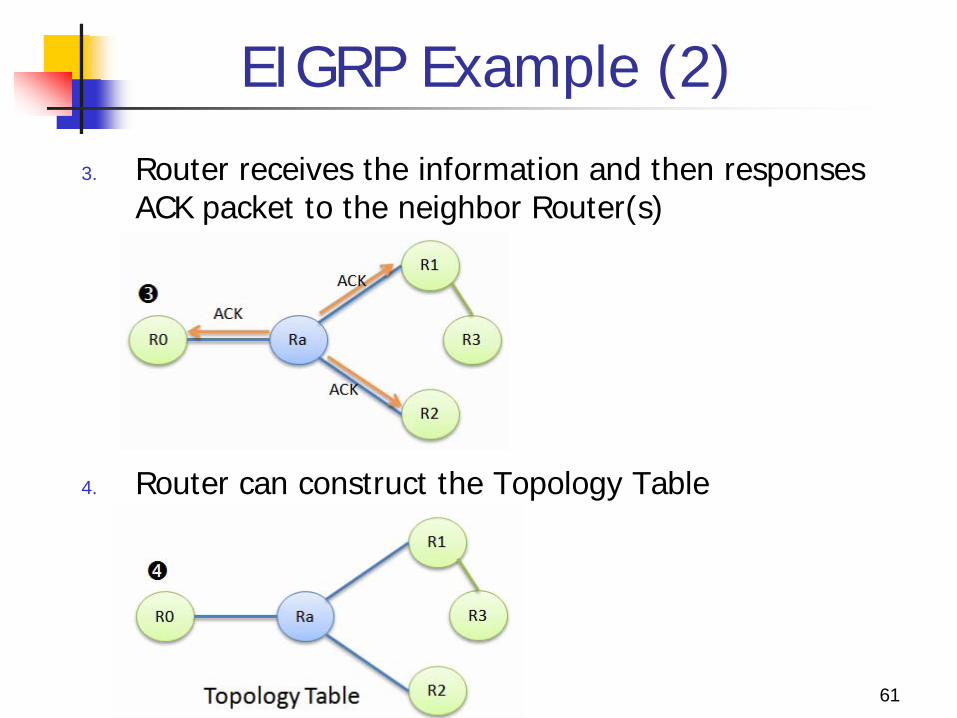
EIGRP Example (2)
3. Router receives the information and then responses ACK packet to the neighbor Router(s)
4. Router can construct the Topology Table
61

EIGRP Example (3) 5. Router transmits its Routing Information to the
neighbor Router(s)
6. The neighbor Router(s) receives the Routing Table of Ra and then sends back ACK
62 如果連結的狀態沒更動,則不會在傳送任何 Routing Table 的訊息!

10 Gigabit Interfaces
63

10 Gigabit Interfaces
The 10 Gigabit Ethernet links can support the increased bandwidth requirements.
Advantage: Unlike the multiple link solution, 10 Gigabit Ethernet
links does not increase routing complexity. The number of routing peers is not increased.
Unlike the EtherChannel solution, the routing protocols will have the ability to deterministically select the best path between the distribution and core layer.
64

Link Load Balancing
65

Link Load Balancing
Many equal cost redundant paths are provided in the recommended network topology from one access switch to the other across the distribution and core switches.
Cisco Express Forwarding is a deterministic algorithm. When packets traverse the network that all use the
same input value to the Cisco Express Forwarding hash, a “go to the right” or “go to the left” decision is made for each redundant path
66

Link Load Balancing with EtherChannel
EtherChannel allows load sharing of traffic among the links in the channel and redundancy in the event that one or more links in the channel fail.
Tune the hashing algorithm used to select the specific EtherChannel link on which a packet is transmitted.
Use the default Layer 3 source and destination information, or you can add a level of load balancing to the process by adding the Layer 4 TCP/IP port information as an input to the algorithm.
67

EtherChannel Load Balancing The default Layer 3 hash algorithm provided about one-third to
two-thirds utilization. When the algorithm included Layer 4 information, nearly full
utilization was achieved with the same topology and traffic pattern. To use Layer 3 plus Layer 4 load balancing to provide as much
information as possible for input to the EtherChannel algorithm to achieve the best or most uniform utilization of EtherChannel members.
68
Link Load Balancing
69

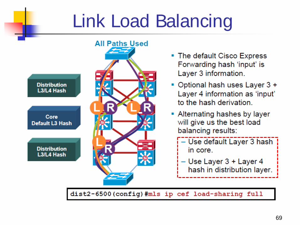
Link Load Balancing
In the core layer, continue to use the default which is based on only Layer 3 information.
In the distribution layer, The default input hash value is Layer 3 for source
and destination. Using Layer 3 with Layer 4, the output hash value
also changes. Use the Layer 3 and Layer 4 information as input
into the Cisco Express Forwarding hashing algorithm with the mls ip cef load-sharing full command
70

Routing Protocol Design
Layer 3 routing protocols are used to quickly reroute around failed nodes or links while providing load balancing over redundant paths.
Routing protocols are usually deployed across the distribution-to-core and core-to-core interconnections.
Layer 3 routing design can be used in the access layer, too, but this design is currently not as common.
71

Build Redundant Triangles
For optimum distribution-to-core layer convergence, build redundant triangles, not squares, to take advantage of equal-cost, redundant paths for the best deterministic convergence.
72

Build Redundant Triangles
In Model A, and uses dual equal-cost paths to avoid timer-based, nondeterministic convergence. Instead of indirect neighbor or route-loss detection using hellos
and dead timers, the triangle design failover is hardware based and relies on physical link loss to mark a path as unusable and reroute all traffic to the alternate equal-cost path.
In contrast, in Model B requires routing protocol convergence to fail over to an alternate path in the event of a link or node failure. It is possible to build a topology that does not rely on equal-
cost, redundant paths to compensate for limited physical fiber connectivity or to reduce cost.
With this design, it is not possible to achieve the same deterministic convergence in the event of a link or node failure, and for this reason the design will not be optimized for high availability. 73