entertainment technology—rigging support points...
TRANSCRIPT

BSR E1.56 – 201x, Rigging Support Points DRAFT Rig/2015-2034r7
Entertainment Technology—Rigging Support Points
Table of Contents
1. GENERAL ____________________________________________________________ 4 1.1 Scope. ___________________________________________________________ 4 1.2 Purpose. __________________________________________________________ 5 1.3 Application. ________________________________________________________ 5 1.4 References. _______________________________________________________ 6
2. DEFINITIONS _________________________________________________________ 8 2.1 Allowable Stress Design (ASD): ________________________________________ 8 2.2 Design Factor: _____________________________________________________ 8 2.3 Characteristic Load: _________________________________________________ 8 2.4 Dead Load: ________________________________________________________ 8 2.5 Detachable Rigging Hardware: _________________________________________ 9 2.6 Fabricated Rigging Hardware: _________________________________________ 9 2.7 Installer: __________________________________________________________ 9 2.8 Load Resistance Factor Design (LRFD): __________________________________ 9 2.9 Live Load: _________________________________________________________ 9 2.10 Lug: ______________________________________________________________ 9 2.11 Mousing: _________________________________________________________ 10 2.12 Nominal Strength: __________________________________________________ 10 2.13 Peak Load: _______________________________________________________ 10 2.14 Person, Authorized: _________________________________________________ 10 2.15 Person, Competent: _________________________________________________ 10 2.16 Person, Designated: ________________________________________________ 10 2.17 Person, Qualified: __________________________________________________ 10 2.18 Registered Design Professional: _______________________________________ 11 2.19 Rigging Point, Permanent: ____________________________________________ 11 2.20 Rigging Point, Temporary: ____________________________________________ 11 2.21 Static Load: _______________________________________________________ 11 2.22 User: ____________________________________________________________ 11 2.23 Working Load Limit (WLL): ___________________________________________ 11
3. DESIGN _____________________________________________________________ 12 3.1 General Requirements. ______________________________________________ 12 3.2 Design Coordination ________________________________________________ 13 3.3 Loads-General ____________________________________________________ 14 3.4 Load Combinations _________________________________________________ 16 3.5 Design Criteria ____________________________________________________ 16 3.5.1 General __________________________________________________________ 16 3.5.2 Steel ____________________________________________________________ 17 3.5.3 Aluminum _________________________________________________________ 18 3.5.4 Concrete _________________________________________________________ 18 3.5.5 Masonry __________________________________________________________ 19
Copyright 2018 ESTA. All rights reserved. Page 1 of 47
BSR E1.56 – 201x, Rigging Support Points DRAFT Rig/2015-2034r7
3.6 Rigging Points: Types _______________________________________________ 20 3.7 Wear and Abrasion _________________________________________________ 21 3.8 Connection Design ________________________________________________ 21 3.9 Distortion and Displacement __________________________________________ 23
4. FABRICATED COMPONENTS ___________________________________________ 24 4.1 General __________________________________________________________ 24 4.2 Fabrication _______________________________________________________ 24
5. DETACHABLE COMPONENTS ___________________________________________ 26 5.1 General __________________________________________________________ 26 5.2 Design __________________________________________________________ 26
6. INSTALLATION _______________________________________________________ 28 6.1 Supervision _______________________________________________________ 28 6.2 Welding __________________________________________________________ 28 6.3 Friction Connections ________________________________________________ 28 6.4 Embedded Hardware _______________________________________________ 28 6.5 Anchors _________________________________________________________ 29 6.6 Interference_______________________________________________________ 29 6.7 Hardware _________________________________________________________ 30
7. TESTING ____________________________________________________________ 31 7.0 New Rigging Points ________________________________________________ 31 7.1 General __________________________________________________________ 31 7.2 Fabricated Assemblies ______________________________________________ 31 7.3 Detachable Assemblies _____________________________________________ 32 7.4 Embedded Anchor Connections _________________________________________ 32 7.5 Welded and Bolted Connections _________________________________________ 33 7.5 34 Existing Rigging Point Load Test Requirements: _______________________________ 34 7.6 Test standards ____________________________________________________ 35
8. INSPECTION, REMOVAL AND REPAIR ____________________________________ 37 8.1 General __________________________________________________________ 37 8.2 Detachable Assemblies _____________________________________________ 37 8.2.2 Frequency of Inspection _____________________________________________ 37 8.3 Documentation ____________________________________________________ 39 8.4 Inspection Training _________________________________________________ 40 8.5 Removal from Service Criteria ________________________________________ 40
9. EXISTING RIGGING POINTS ____________________________________________ 41 9.1 Verification by Analysis ______________________________________________ 41 9.2 Verification by Testing ______________________________________________ 41 9.3 Loads Acting on Existing Structures ____________________________________ 42
10. DOCUMENTATION ____________________________________________________ 43 10.1 General __________________________________________________________ 43
11. LABELING ___________________________________________________________ 45 11.1 General. _________________________________________________________ 45 11.2 Rigging Point Identification ___________________________________________ 45 11.3 Maintenance of Identification _________________________________________ 45 11.4 Replacement of Identification _________________________________________ 46 11.5 Method of labeling. _________________________________________________ 46
Copyright 2018 ESTA. All rights reserved. Page 2 of 47

BSR E1.56 – 201x, Rigging Support Points DRAFT Rig/2015-2034r7
11.6 Label Attachment __________________________________________________ 46 Appendix 1 ______________________________________________________________ 47
A1.1 User Design Loads _________________________________________________ 47 Characteristic Load: _____________________________________________________ 47 Peak Load: ____________________________________________________________ 47
Copyright 2018 ESTA. All rights reserved. Page 3 of 47

BSR E1.56 – 201x, Rigging Support Points DRAFT Rig/2015-2034r7
1. GENERAL
NOTE TO THE USER: Explanatory Information (contained in the right-hand column of this document) is intended to provide additional NON-MANDATORY commentary and information regarding the scope of this standard. This information is intended to provide additional clarification regarding the thoughts of the authors during the writing of this document. In addition, the user may find notes on industry standard practices and, references and resources for additional information regarding each topic at hand. It is the hope of the authors that users of this document will find that the proximity of this commentary particularly useful to their understanding of this document.
1.1 Scope. This Standard applies to stationary Rigging Points attached to permanent facility structure that are intended to be permanent and provides minimum requirements for the design, fabrication, installation, inspection and documentation of these Rigging Points for their use to support rigging loads. Applicability of this standard is not dependent on direction of the applied force or duration of the applied load. This standard applies to Rigging Points that are stationary under load.
E1.1 While this standard is intended to cover all structures, it is hoped that “non-traditional” entertainment structures such as hotel ballrooms, atriums in office buildings, schools, and other structures will particularly benefit from this standard. This standard does not apply to engineering analysis of structures supporting rigging points. The application of new loads to existing structures, and the location of those loads, must be considered by the user. Concentrated loads, multiple loads acting in close proximity and other load combinations have the potential to exceed existing building structural capacity. It is strongly recommended that structures supporting new loads be reviewed by a qualified person. This standard does not apply to
• Connection of any loads to the rigging point. • Connections to temporary entertainment
structures. • Equipment “below the hook”. • Rigging points that are intended to be
temporary in nature.
STANDARD REQUIREMENTS EXPLANATORY INFORMATION (Not requirements of E1.56)
Copyright 2018 ESTA. All rights reserved. Page 4 of 47

BSR E1.56 – 201x, Rigging Support Points DRAFT Rig/2015-2034r7
1.2 Purpose. The purpose of this document is to provide standards for the design, fabrication, installation, inspection and documentation of Rigging Points. These standards are intended for the use of the entertainment rigging community, facility managers and design professionals. It is the intent of this document to ensure that design and use criteria as established within this document are met by those materially affected by the standards contained within this document. The design and installation of rigging points shall occur according to the generally accepted principles of structural engineering, this document, and applicable codes and standards as referenced herein.
E1.2 It is the intent of this document to clearly define the types of loading acting on rigging points including, but not limited to:
• Horizontal • Vertical • Dynamic • Cyclical
This standard will provide guidance on adequate capacity to support the intended loads; including criteria for appropriate load factors and load combinations. This standard provides means of validating the allowable load capacity of existing rigging points. This document describes the various types of loading that may be encountered in the use of rigging points and provides design factors for the safe use of the points. It is the hope of this committee that this standard is useful to the broad engineering and facility management community including professionals not specializing in the entertainment field, as well as code officials and others.
1.3 Application. This standard applies to rigging as typically used by the entertainment industry and allied industries. The criteria contained in this document are intended to be used by design professionals for the design of Rigging Points and by workers using Rigging Points. It provides requirements for the design and use of Rigging Points to be used for support of entertainment loads on structures.
E1.3 This standard addresses the following issues regarding the use and application of rigging points:
• Structural integrity • Functionality • Intended use • Environmental
o Corrosion • Applicable standards
Copyright 2018 ESTA. All rights reserved. Page 5 of 47

BSR E1.56 – 201x, Rigging Support Points DRAFT Rig/2015-2034r7
1.4 References. The documents listed below are provided for informational purposes. This standard incorporates by reference only specifically noted sections and provisions. Where there is a conflict between design criteria provided by this standard and any of the documents incorporated herein by reference, the most stringent standard shall apply.
E1.4 Referenced standards are those documents referenced in the 2012 International Building Code. For standards not referenced in the 2012 IBC; the standard is the version that was current at the publication of this document.
American Institute of Steel Construction • Specification for Structural Steel Buildings,
ANSI/AISC 360—10 • Seismic Provisions for Structural Steel
Buildings, ANSI/AISC 341—10
Aluminum Association • Aluminum Design Manual; —ADM—2015
American Concrete Institute • Building Code Requirements for Structural
Concrete; 318—11 • Building Code Requirements for Masonry
Structures; 530—11
American National Standards Institute • Entertainment Technology – Powered Hoist
Systems; E1.6-1 – 2012 • Selection and Use of Chain Hoists in the
Entertainment Industry; ANSI E1.6-3 – 2012 • Entertainment Technology--Loudspeaker
Enclosures Intended for Overhead Suspension--Classification, Manufacture and Structural Testing; ANSI E1.8 – 2012
Copyright 2018 ESTA. All rights reserved. Page 6 of 47

BSR E1.56 – 201x, Rigging Support Points DRAFT Rig/2015-2034r7
American Society of Mechanical Engineering • Below-the-Hook Lifting Devices--Safety
Standard for Cableways, Cranes, Derricks, Hoist, Hooks, Jacks, and Slings;
o ASME B30.9 – Slings o ASME B30.10 – Hooks o ASME B30.20 – Below the Hook
Lifting Devices o ASME B30.26 – Rigging Hardware o Design of Below-the-hook Lifting
Devices; ASME BTH-1 – 2014
American Welding Society
• Structural Welding Code—Steel; D1.1/D1.1M:2015,
• Structural Welding Code—Aluminum; D1.2/D1.2M:2014,
International Code Council
• 2012 International Building Code
The suite of ASME B30 Standards for Overhead Lifting is a useful guide for many overhead rigging and lifting operations. Items where these standards may be useful include:
• Proper use of hardware • Use of pre-fabricated hardware that may
be used in assembly of permanent Rigging Points
• Standards for the use of equipment and materials that are similar to equipment and materials used in the installation of Rigging Points
Copyright 2018 ESTA. All rights reserved. Page 7 of 47

BSR E1.56 – 201x, Rigging Support Points DRAFT Rig/2015-2034r7
2. DEFINITIONS 2.1 Allowable Stress Design (ASD): A structural engineering analysis method in which service load stresses remain below a given stress limit divided by a specified safety factor. Note: The stress limits and factors vary depending on what failure mode is being examined, such as tensile rupture of flexural yielding.
2.2 Design Factor: A ratio of the design load limit to the nominal strength of a material or component.
2.2.1 For ASD, the minimum design factor specified shall replace the appropriate safety factor from the design code being applied.
2.2.2 For LRFD, the LRFD live load factor divided by the minimum design factor specified, shall replace the resistance factor from the design code being applied.
2.3 Characteristic Load: The maximum force applied to a Rigging Point resulting from normal intended operating conditions whether or not the load acting on the Rigging Point is at rest or in motion. This includes the Working Load Limit (WLL), equipment self-weight, and dynamic forces in normal use.
2.4 Dead Load: The self-weight of the rigging point.
STANDARD REQUIREMENTS EXPLANATORY INFORMATION (Not requirements of E1.56)
Copyright 2018 ESTA. All rights reserved. Page 8 of 47
BSR E1.56 – 201x, Rigging Support Points DRAFT Rig/2015-2034r7
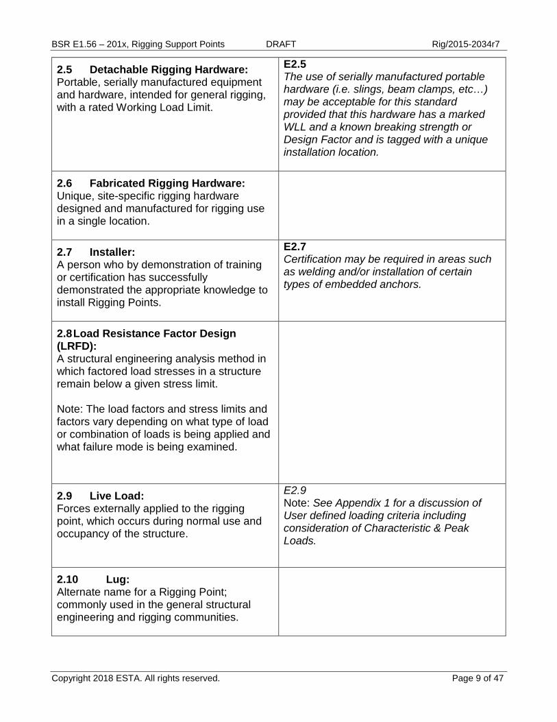
2.5 Detachable Rigging Hardware: Portable, serially manufactured equipment and hardware, intended for general rigging, with a rated Working Load Limit.
E2.5 The use of serially manufactured portable hardware (i.e. slings, beam clamps, etc…) may be acceptable for this standard provided that this hardware has a marked WLL and a known breaking strength or Design Factor and is tagged with a unique installation location.
2.6 Fabricated Rigging Hardware: Unique, site-specific rigging hardware designed and manufactured for rigging use in a single location.
2.7 Installer: A person who by demonstration of training or certification has successfully demonstrated the appropriate knowledge to install Rigging Points.
E2.7 Certification may be required in areas such as welding and/or installation of certain types of embedded anchors.
2.8 Load Resistance Factor Design (LRFD): A structural engineering analysis method in which factored load stresses in a structure remain below a given stress limit. Note: The load factors and stress limits and factors vary depending on what type of load or combination of loads is being applied and what failure mode is being examined.
2.9 Live Load: Forces externally applied to the rigging point, which occurs during normal use and occupancy of the structure.
E2.9 Note: See Appendix 1 for a discussion of User defined loading criteria including consideration of Characteristic & Peak Loads.
2.10 Lug: Alternate name for a Rigging Point; commonly used in the general structural engineering and rigging communities.
Copyright 2018 ESTA. All rights reserved. Page 9 of 47

BSR E1.56 – 201x, Rigging Support Points DRAFT Rig/2015-2034r7
2.11 Mousing: Securing from rotation or loosening of any threaded device.
2.12 Nominal Strength: Strength of a structure or a component (without the ASD safety factor or the LRFD resistance factor applied) to resist load effects, as determined in accordance with this specification.
E2.12 This definition is used as a replacement for ultimate strength. Nominal Strength is the maximum capacity of any structural element based upon the appropriate failure mode.
2.13 Peak Load: The maximum force applied to a Rigging Point resulting from abnormal conditions whether or not the load acting on the Rigging Point is at rest or in motion.
E2.13 Examples include the effects of emergency stops, uncontrolled stops, stalling of equipment and extreme environmental conditions.
2.14 Person, Authorized: A person who is assigned by the employer to take particular actions or execute tasks.
E2.14 For the purposes of the Standard, Authorized Person generally refers to a person authorized to apply loads to a Rigging Point.
2.15 Person, Competent: A person who is capable of identifying existing and predictable hazards in the workplace, and who is authorized to take prompt corrective measures to eliminate them.
2.16 Person, Designated: A competent person designated by the employer to perform a task.
2.17 Person, Qualified: A person who, by possession of a recognized degree or certificate of professional standing, or who, by extensive knowledge, training, and experience, has successfully demonstrated the ability to solve or resolve problems relating to the subject matter and work.
Copyright 2018 ESTA. All rights reserved. Page 10 of 47

BSR E1.56 – 201x, Rigging Support Points DRAFT Rig/2015-2034r7
2.18 Registered Design Professional: An individual who is registered or licensed to practice their respective design profession as defined by the statutory requirements of the professional registration laws of the state or jurisdiction in which the project is to be constructed.
2.19 Rigging Point, Permanent: A rigging point that is intended to remain in place for the life of the structure. Rigging points that are intended to remain in place for a period greater than 90 days shall be treated as permanent.
2.20 Rigging Point, Temporary: A rigging point that is intended to remain in place for a designated period of less than 90 days.
2.21 Static Load: A constant force, that may be applied to a rigging point, often measured as weight.
2.22 User: A person who performs activities related to the use of Rigging Points.
2.23 Working Load Limit (WLL): The maximum weight static load that the user may apply to a rigging point.
E2.23 “Rated Capacity” and “Rated Load” are commonly used to describe Working Load Limit.
Copyright 2018 ESTA. All rights reserved. Page 11 of 47

BSR E1.56 – 201x, Rigging Support Points DRAFT Rig/2015-2034r7
STANDARD REQUIREMENTS EXPLANATORY INFORMATION (Not requirements of E1.56)
3. DESIGN 3.1 General Requirements.
3.1.1 The intent of this section is to establish requirements for the design and engineering of rigging points. Variations on the design requirements shall be permitted pursuant to review and approval by a Professional Engineer.
3.1.2 Design shall reference all applicable loads and load combinations. Load combinations shall be based upon the most current International Building Code.
E3.1.2 The design factors in this document are based on ASD (Allowable Strength Design) methods. Load Factored Resistance Design (LRFD) may also be used.
3.1.3 Design shall be performed by a registered design professional. Exception: Rigging Points exclusively assembled with Detachable Rigging Hardware and connected to the structure by use of clamps, slings or similar attachments that do not require drilling or welding shall be designed by a qualified person or a registered design professional.
3.1.4 As an alternate to component design, components may be approved by proof testing according to the provisions of Section 7.
Copyright 2018 ESTA. All rights reserved. Page 12 of 47

BSR E1.56 – 201x, Rigging Support Points DRAFT Rig/2015-2034r7
3.2 Design Coordination Rigging Point designers shall coordinate the capacity, location and quantity of the Rigging Points with the facility. This shall include, but not be limited to: 1. Working Load Limit (WLL) 2. Location of Rigging Points within the existing structure 3. Line of action of loads and forces (load direction) acting on the Rigging Point(s) 4. Protection of the Rigging Points from environmental deterioration 5. Accessibility for inspection and maintenance.
E3.2 Although it is outside of the scope of this standard; prior to first use of any new rigging points (or use of any existing rigging points that have been reviewed according to this standard), we strongly recommend that existing structure capacity to support loads from Rigging Points should be approved by a qualified person. Entertainment industry equipment suppliers and consultants can provide guidance in the area of Rigging Point layout. Common rigging design loads in the entertainment industry are 1,000 pounds and 2,000 pounds. These design loads are often based on common hoists as used in this industry. ½ ton, 1 ton and 2 ton hoists are very common. It is strongly suggested that rigging points be designed at a minimum to meet these common criteria. The facility structure should take into account the location and layout of the rigging points. Rigging is typically installed in a grid pattern that aligns with industry standard components such as truss, used in 10’ sections. Consideration should be given to the layout of the rigging points within the facility. Ease of access and visibility for future inspections is very important. Designing with inspections in mind by limiting the number of hardware pieces used and marking hardware to be visible from below can help to keep inspectors from working at height, further limiting risk and liability.
Copyright 2018 ESTA. All rights reserved. Page 13 of 47

BSR E1.56 – 201x, Rigging Support Points DRAFT Rig/2015-2034r7
3.3 Loads-General
3.3.1 Analysis shall be based on all applicable load combinations. Analytical review shall include the Rigging Point, Rigging Point connections and the strength of any connection to the supporting structure.
3.3.2 Loads, forces and force effects acting on the rigging point shall include (as applicable): 1. Dead loads 2. Live loads 3. Environmental loads
E3.3.2 Consideration should be placed on all loads and forces including: Forces 1. Vertical forces 2. Horizontal forces 3. Lateral forces 4. Rotational forces 5. Seismic forces Force Effects 1. Forces that cause rotational effects 2. Forces that cause cyclical effects
3.3.2.1 Loads, forces and force effects, including the effects of dynamic forces, used for Rigging Point design shall be considered in the determination of Characteristic Loads and Peak Loads.
E3.3.2.1 A dynamic load factor of 1.25 to 1.4 is frequently applied to rigging hardware and equipment intended for support of powered chain hoists, which are typically used to support temporary loads resulting from equipment used in the concert touring industries and, for similar events. Higher dynamic load factors may be appropriate for Rigging Points that support high-speed lifting and lowering operations.
Copyright 2018 ESTA. All rights reserved. Page 14 of 47

BSR E1.56 – 201x, Rigging Support Points DRAFT Rig/2015-2034r7
3.3.3 Load analysis shall include the effect of stress reversal. This shall include the consideration of fatigue due to multiple stress reversals.
3.3.3 Initiation of failure due to fatigue is complex. Failure at stresses below yield can occur when fatigue or “brittle fracture” govern. These phenomena can occur in areas of high combined stresses; at locations of impact loading; at locations with notches or abnormalities that can lead to stress concentrations and due to other items. Repetitive loading and unloading and/or cyclical application of loads may also be causes of fatigue. Resources for information regarding fatigue analysis and design include:
• The Steel Construction Manual, American Institute of Steel Construction, 14th Edition
o Fatigue & Fracture Control, Page 2-40 • Specification for Structural Steel Buildings,
American Institute of Steel Construction, June 22, 2010
o Appendix 3, Design for Fatigue, Page 16.1-192
• The Aluminum Design Manual 2015, The Aluminum Association
o Part 1: Specification for Aluminum Structures, Appendix 3 Design for Fatigue
3.3.4 The allowable direction of loads applied to a Rigging Point shall be defined.
Copyright 2018 ESTA. All rights reserved. Page 15 of 47

BSR E1.56 – 201x, Rigging Support Points DRAFT Rig/2015-2034r7
3.3.5 Working Load Limit (WLL)
3.3.5.1 All Rigging Points shall have a WLL. The WLL shall define the maximum weight or static load that can be applied to the rigging point. Determination of the maximum weight or Static Load applied shall be the responsibility of the User. It is the responsibility of the User to ensure that the applied weight or Static Load shall not exceed the WLL.
E3.3.5.1 See Appendix 1 for a discussion of user defined loads that may be applied to Rigging Points.
3.4 Load Combinations
3.4.1 Design criteria shall be based on the controlling load combination.
3.4.2 Load combinations shall be based on the International Building Code, current edition.
3.5 Design Criteria
E3.5 This section is based on ASME “BTH-1—2014; Design of Below-the-Hook Lifting Devices” (BTH). BTH provides design criteria for items such as lifting beams & spreader beams. For the most severe category of lifting beams (those with loads that can be unpredictable, variable, and/or severe) BTH uses a basic design factor of 3.0. DF in this standard derive from stress values in BTH.
3.5.1 General
3.5.1.1. Design Factors (DF) and material specific design criteria are contained in this section.
Copyright 2018 ESTA. All rights reserved. Page 16 of 47
BSR E1.56 – 201x, Rigging Support Points DRAFT Rig/2015-2034r7
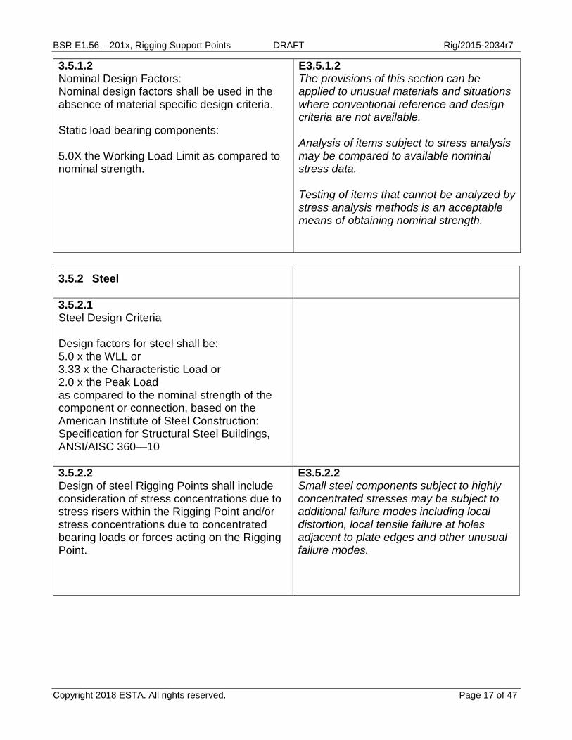
3.5.1.2 Nominal Design Factors: Nominal design factors shall be used in the absence of material specific design criteria. Static load bearing components: 5.0X the Working Load Limit as compared to nominal strength.
E3.5.1.2 The provisions of this section can be applied to unusual materials and situations where conventional reference and design criteria are not available. Analysis of items subject to stress analysis may be compared to available nominal stress data. Testing of items that cannot be analyzed by stress analysis methods is an acceptable means of obtaining nominal strength.
3.5.2 Steel
3.5.2.1 Steel Design Criteria Design factors for steel shall be: 5.0 x the WLL or 3.33 x the Characteristic Load or 2.0 x the Peak Load as compared to the nominal strength of the component or connection, based on the American Institute of Steel Construction: Specification for Structural Steel Buildings, ANSI/AISC 360—10
3.5.2.2 Design of steel Rigging Points shall include consideration of stress concentrations due to stress risers within the Rigging Point and/or stress concentrations due to concentrated bearing loads or forces acting on the Rigging Point.
E3.5.2.2 Small steel components subject to highly concentrated stresses may be subject to additional failure modes including local distortion, local tensile failure at holes adjacent to plate edges and other unusual failure modes.
Copyright 2018 ESTA. All rights reserved. Page 17 of 47
BSR E1.56 – 201x, Rigging Support Points DRAFT Rig/2015-2034r7
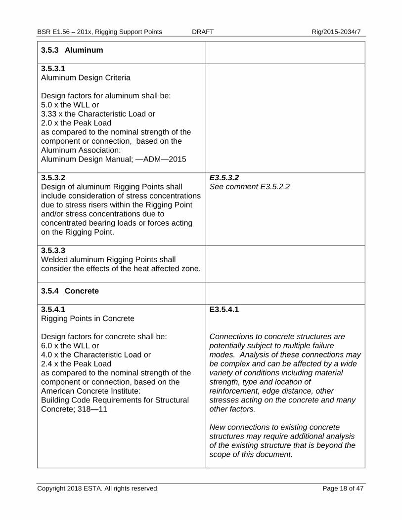
3.5.3 Aluminum
3.5.3.1 Aluminum Design Criteria Design factors for aluminum shall be: 5.0 x the WLL or 3.33 x the Characteristic Load or 2.0 x the Peak Load as compared to the nominal strength of the component or connection, based on the Aluminum Association: Aluminum Design Manual; —ADM—2015
3.5.3.2 Design of aluminum Rigging Points shall include consideration of stress concentrations due to stress risers within the Rigging Point and/or stress concentrations due to concentrated bearing loads or forces acting on the Rigging Point.
E3.5.3.2 See comment E3.5.2.2
3.5.3.3 Welded aluminum Rigging Points shall consider the effects of the heat affected zone.
3.5.4 Concrete
3.5.4.1 Rigging Points in Concrete Design factors for concrete shall be: 6.0 x the WLL or 4.0 x the Characteristic Load or 2.4 x the Peak Load as compared to the nominal strength of the component or connection, based on the American Concrete Institute: Building Code Requirements for Structural Concrete; 318—11
E3.5.4.1 Connections to concrete structures are potentially subject to multiple failure modes. Analysis of these connections may be complex and can be affected by a wide variety of conditions including material strength, type and location of reinforcement, edge distance, other stresses acting on the concrete and many other factors. New connections to existing concrete structures may require additional analysis of the existing structure that is beyond the scope of this document.
Copyright 2018 ESTA. All rights reserved. Page 18 of 47

BSR E1.56 – 201x, Rigging Support Points DRAFT Rig/2015-2034r7
3.5.5 Masonry
3.5.5.1 Rigging Points in Masonry Design factors for masonry shall be: 6.0 x the WLL or 4.0 x the Characteristic Load or 2.4 x the Peak Load as compared to the nominal strength of the component or connection, based on the American Concrete Institute: Building Code Requirements for Masonry Structures; 530—11
Copyright 2018 ESTA. All rights reserved. Page 19 of 47

BSR E1.56 – 201x, Rigging Support Points DRAFT Rig/2015-2034r7
3.6 Rigging Points: Types
E3.6 The Rigging Point must include the ‘full assembly”. A “full assembly” includes all components that are intended to be permanent in the load path, including connection of the Rigging Point to the supporting structure.
3.6.1 General Use Rigging Points
E3.6.1 General Use Rigging Points are very common in active environments where rigging is installed and removed frequently. The system designer should consult with the client to be sure that they are using the correct design criteria for each type of Rigging Point.
3.6.1.1 Loads acting on General Use points may include any combination of forces. Forces may act in any allowable direction.
E3.6.1.1 It is considered good practice to design General Use Rigging Points for a 20 degree off-axis load.
3.6.1.2 Design of General Use points shall consider all applicable load and force combinations.
3.6.1.3 General Use points shall consider all combined stresses.
E3.6.1.3 Analysis methods for considering combined stresses may include a principle stress analysis using Mohr’s circle methods, computerized FEA methods or other methods to ensure that all maximum stress combinations are considered during design. Well-designed tests may also be utilized to ensure a safe design.
3.6.2 Single Axis Rigging Points
E3.6.2 Rigging points with loads acting along a single axis are less common in general use. The system designer should carefully coordinate the intended use of the Rigging Point with the client.
Copyright 2018 ESTA. All rights reserved. Page 20 of 47

BSR E1.56 – 201x, Rigging Support Points DRAFT Rig/2015-2034r7
3.6.2.1 Loads acting on Single Axis Rigging Points shall act axially in-line with the intended load axis of the Rigging Point. The designer shall consider the effect of a 5 degree off-axis load acting on Single Axis Rigging Points.
E3.6.2.1 The effect of a 5-degree off axis load is intended to ensure a minimum level of robustness in the design of Single Axis Rigging Points. Any deviation of the load from a true vertical load axis may result in interference with items within the facility. Physical limitations, such as false ceilings and other obstructions, may require stringent “off axis” load criteria to prevent any such interference. Rigging Points that cannot realistically meet the criteria for a Single Axis Rigging Point must be designed according to the provisions for a General Use Rigging Point.
3.7 Wear and Abrasion
3.7.1 Rigging Points subject to allowable wear and abrasion shall be designed to be within accepted tolerances at the end of their anticipated life.
3.7.2 Points subject to expected material loss due to wear and/or abrasion shall be designed to accommodate the expected wear. Allowable wear limits shall be established, wear shall be monitored by a permanent wear mark or by use of a gauge or graphic tag on each Rigging Point.
3.8 Connection Design
E3.8 This standard does not address the strength of existing structures to support Rigging Points. However, the designer should exercise all due diligence to ensure that the owner of the existing structure has taken appropriate action to ensure that the Rigging Point loads can be safely connected to and supported by the existing structure.
Copyright 2018 ESTA. All rights reserved. Page 21 of 47

BSR E1.56 – 201x, Rigging Support Points DRAFT Rig/2015-2034r7
3.8.1 Rigging Point design shall include design of the connection of the Rigging Point to all structures.
E3.8.1 Connection types can include welded connections, bolted connections, friction connections or other proprietary connections (i.e.: Connectors as manufactured by Lindapter, LNA, Unistrut, Doughty and others), and methods similar to “temporary” or “rock and roll/arena rigging”, which are intended to be permanently installed.
3.8.2 Design of connections shall be based on design criteria as set forth in this document, the International Building Code, current edition and related material standards.
E3.8.2 Knowledge of the material strength of the existing structure is essential to determining the strength of the Rigging Point. It is not possible to know the full capacity of a Rigging Point without also knowing the full strength and capacity of its connection. Rigging Points that will be attached to existing concrete structures may require detailed knowledge of the existing structure and, coordination with the Engineer of Record for that structure. Concentrated loads on concrete structures, for example, may appear to be acceptable when ONLY the strength of a connection anchor is considered. However, the new Rigging Point load may affect the strength of the existing concrete structure in unanticipated ways.
Copyright 2018 ESTA. All rights reserved. Page 22 of 47

BSR E1.56 – 201x, Rigging Support Points DRAFT Rig/2015-2034r7
3.9 Distortion and Displacement
3.9.1 Rigging Points shall be designed to prevent distortion, displacement or rotation of the Rigging Point assembly. Note: An exception would be hardware that is designed to rotate.
E3.9.1 Rigging Point components that are subject to elastic behavior (such as steel or aluminum plates) when properly designed should not experience significant local distortion under load. Rigging Point components that are assembled from flexible materials (such as steel wire rope) should be designed and installed in such a way that any displacement under load (whether vertical or horizontal) shall not cause the assembly to interfere with the structure or other Rigging Points or cause the hung assembly to behave unsuitably Mounting hardware must be prevented from rotating or loosening by appropriate locking methods. Swivel rings that allow supported loads to rotate are an example of hardware that is an exception to rotational restrictions. However, care must be taken to ensure that mounting hardware for these types of systems are secured as appropriate.
Copyright 2018 ESTA. All rights reserved. Page 23 of 47

BSR E1.56 – 201x, Rigging Support Points DRAFT Rig/2015-2034r7
STANDARD REQUIREMENTS EXPLANATORY INFORMATION (Not requirements of E1.56)
4. FABRICATED COMPONENTS 4.1 General This section shall address Rigging Points assembled from fabricated components or a combination of Fabricated Components and detachable rigging components. Note: See Section 2.3 for a definition of “Fabricated Components” as referenced in this document.
E4.1 Additional information regarding testing and design factors for mass manufactured items may be found in ASME B30 documents. Additional information regarding testing and design factors for fabricated items may be found in the 2012 IBC.
4.1.1 Fabricated Component Rigging Points are unique assemblies manufactured from Fabricated Components or a combination of Fabricated Components and Detachable Rigging Hardware. These assemblies shall be intended for use in a single location or installation.
E4.1.1 Users and installers should clearly understand that Fabricated Components installed in certain locations may locally overstress the material to which the Fabricated Component is attached.
4.1.2 The WLL of Fabricated Component assemblies shall be determined by design or by testing. Design shall be according to the provisions of Section 3. Testing shall be according to the provisions of Section 7.
4.2 Fabrication Rigging Points shall be fabricated from new materials of verifiable origin.
Copyright 2018 ESTA. All rights reserved. Page 24 of 47

BSR E1.56 – 201x, Rigging Support Points DRAFT Rig/2015-2034r7
4.2.1 Where the components are in contact with, or are fastened to dissimilar materials, reactive materials shall be kept from direct contact with other dissimilar materials by painting, powder coating or use of a barrier material.
Copyright 2018 ESTA. All rights reserved. Page 25 of 47
BSR E1.56 – 201x, Rigging Support Points DRAFT Rig/2015-2034r7
STANDARD REQUIREMENTS EXPLANATORY INFORMATION (Not requirements of E1.56)
5. DETACHABLE COMPONENTS 5.1 General This section shall address Rigging Points assembled from serially manufactured components intended for overhead rigging.
E5.1 Users and installers should clearly understand that Detachable Components installed in certain locations may locally overstress the material to which the Detachable Component is attached.
5.1.1 Detachable Component Rigging Points are manufactured from Detachable Rigging Hardware. Individual or multiple Detachable Components may be used to assemble a Rigging Point.
E5.1.1 OSHA 1926.251 may be referenced for use and design criteria for fabricated components.
5.1.2 All detachable components used in the assembly of rigging points shall have use criteria defined by the manufacturer. Use criteria shall include WLL and any use limitations such as the allowable direction of the applied load or force acting on the component.
E5.1.2 Additional use criteria may include a diagram indicating the allowable direction of applied load or language indicating that the component may not be subject to side loading.
5.1.3 Components that can be installed without the use of tools shall be secured with tamper-evident methods such as mousing, installation of cotter pins, heat-resistant thread lock or, shall be of a type that, once applied, cannot be removed without showing evidence of having been removed.
5.2 Design
5.2.1 Individual components shall meet the provisions of the standards in Section 1.4
Copyright 2018 ESTA. All rights reserved. Page 26 of 47

BSR E1.56 – 201x, Rigging Support Points DRAFT Rig/2015-2034r7
5.2.2 Component assemblies shall meet the provisions of this section and the provisions in Section 3.
Copyright 2018 ESTA. All rights reserved. Page 27 of 47

BSR E1.56 – 201x, Rigging Support Points DRAFT Rig/2015-2034r7
STANDARD REQUIREMENTS EXPLANATORY INFORMATION (Not requirements of E1.56)
6. INSTALLATION 6.1 Supervision All installation of materials and equipment shall be performed or supervised by a competent person.
6.1.1 Installation methods not provided for in the general provisions of the IBC shall be approved in accordance with Chapter 17 of the IBC, Special Inspections and Testing. (see also 3.4.1)
6.2 Welding All welding shall be performed according to the appropriate referenced standard. All welding shall be performed by certified welders.
6.2.1 Welding Codes: AWS-D1.1 Structural Welding Code - Steel AWS-D1.2 Structural Welding Code – Aluminum
6.3 Friction Connections Friction connections shall be installed according to an approved installation plan as provided by a qualified person. Proprietary friction connectors shall be installed in accordance with the manufacturer’s specification.
6.4 Embedded Hardware Embedded hardware (plates, bolts, channels, etc.) shall be installed according to an approved installation plan as provided by a qualified person and in accordance with the manufacturer’s specification.
E.6.4 Users and installers should clearly understand that Embedded Hardware installed in certain locations may locally overstress the material to which the Embedded Hardware is attached.
6.4.1 The location of embedded hardware shall be approved by a qualified person.
Copyright 2018 ESTA. All rights reserved. Page 28 of 47

BSR E1.56 – 201x, Rigging Support Points DRAFT Rig/2015-2034r7
6.5 Anchors Note: This section applies to “drill-in” anchors installed in existing concrete and masonry.
E.6.5 Users and installers should clearly understand that anchors installed in certain locations may locally overstress the material to which the anchor is attached.
6.5.1 Chemical anchors shall be installed according to an approved installation plan as provided by a qualified person and in accordance with the manufacturer’s specification.
6.5.2 Expansion anchors shall be installed according to an approved installation plan as provided by a qualified person and in accordance with the manufacturer’s specification.
6.5.3 Location of Anchors The location of anchors shall be approved by a qualified person.
E6.5.3 Concrete beams typically have an uncracked and a cracked zone. The cracked zone is typically located at the bottom of the beam, below the “neutral axis”. The design of anchors installed in this area of a concrete beam, for example, need to be considered to ensure a safe installation. The designer should consider the stress state of the concrete into which the anchor is installed.
6.5.4 Interference of Anchors with Existing Embedded Items Anchors shall not interfere with existing embedded steel reinforcing bars, steel pre-stress cables, steel post-tensioned cables or any other embedded items located within existing structure.
E6.5.4 Under the best circumstances, it can be difficult to ensure that concrete anchors installed into existing structures do not interfere with existing reinforcing. CAUTION must be employed when drilling into existing structures. Installation should not proceed without plans approved by a qualified person.
6.6 Interference Rigging Points shall not interfere with adjacent systems or access requirements.
Copyright 2018 ESTA. All rights reserved. Page 29 of 47

BSR E1.56 – 201x, Rigging Support Points DRAFT Rig/2015-2034r7
6.7 Hardware • Hardware shall be of known material and
verifiable origin. • Must have a Working Load Limit (WLL) or,
rated capacity. • If a rated capacity or WLL is unknown, a
written minimum breaking strength must be obtained from the manufacturer or supplier. Hardware without a rated capacity, WLL or minimum breaking strength shall not be used.
Copyright 2018 ESTA. All rights reserved. Page 30 of 47
BSR E1.56 – 201x, Rigging Support Points DRAFT Rig/2015-2034r7
STANDARD REQUIREMENTS EXPLANATORY INFORMATION (Not requirements of E1.56)
7. TESTING 7.0 New Rigging Points
7.1 General Rigging Points shall be proof tested according to the provisions of this section and appropriate standards. Exceptions:
1. Fabricated Component Rigging Point assemblies that have been designed by a qualified person are not required to be proof tested.
7.2 Fabricated Assemblies
7.2.1 Prior to installation, all new Fabricated Component Rigging Point assemblies shall be proof tested. Proof test criteria shall be developed by the manufacturer or a qualified person.
E7.2.1 ANSI B.30.26 has provisions for similar proof load requirements for rigging hardware and accessories.
7.2.1.1 Prior to initial installation, representative samples of identical Fabricated Component Rigging Point assemblies may be approved based upon a test procedure incorporating probabilistic methods developed by a qualified person that simulates applicable loading and deformation conditions.
7.2.2 The proof load for assemblies tested prior to installation shall be a minimum of 2 times the required WLL. The direction of application of the proof load shall be the same as the intended use.
Copyright 2018 ESTA. All rights reserved. Page 31 of 47

BSR E1.56 – 201x, Rigging Support Points DRAFT Rig/2015-2034r7
7.3 Detachable Assemblies
7.3.1 Inspection and/or testing prior to first use shall be according to recommendations of the manufacturer or a qualified person.
E7.3.1 Generally, detachable assemblies do not require testing as they are made from engineered serially manufactured components. However, under some circumstances, it may be desirable to test these assemblies based on expert guidance.
7.4 Embedded Anchor Connections
7.4.1 Prior to initial use, all new Rigging Points incorporating embedded anchors shall be proof tested. Exception: Probabilistic methods may be used to test a sample of embedded anchors, see 7.4.4.1.
7.4.2 Testing criteria shall be developed by a qualified person.
7.4.3 Testing shall be performed by the installer or a competent person.
7.4.4 Proof Load Requirements for embedded anchors: The proof load shall be a minimum of 1.25 times the required WLL. The direction of application of the proof load shall be the same as the intended use.
E7.4.4 Higher proof load requirements may be used if they are approved by a qualified person. Care must be taken to ensure that existing structural systems are not overloaded during testing.
7.4.4.1 Representative samples of identical embedded anchor assemblies may be approved based upon a test procedure incorporating probabilistic methods developed by a qualified person.
E7.4.4.1 Older concrete structures may require testing of all embedded anchors due to a lack of quality control for structures of this nature. This especially applies to structures built prior to 1940.
Copyright 2018 ESTA. All rights reserved. Page 32 of 47

BSR E1.56 – 201x, Rigging Support Points DRAFT Rig/2015-2034r7
7.5 Welded and Bolted Connections
7.5.1 Prior to initial use, a representative sample of new Rigging Points incorporating welded or bolted connections shall be proof tested.
7.5.2 Testing criteria shall be developed by a qualified person.
7.5.3 Testing shall be performed by the installer or a competent person.
7.5.4 Proof Load Requirements for welded or bolted connections: The proof load shall be a minimum of 1.25 times the required WLL. The direction of application of the proof load shall be the same as the intended use.
7.5.4.1 Probabilistic testing shall be based upon a test procedure incorporating approved methods developed by a qualified person.
Copyright 2018 ESTA. All rights reserved. Page 33 of 47

BSR E1.56 – 201x, Rigging Support Points DRAFT Rig/2015-2034r7
7.5 Existing Rigging Point Load Test Requirements: In-Situ Load Tests
7.5.1 Whenever there is a reasonable doubt as to the load-bearing capacity of an existing Rigging Point or portion thereof for the expected loads, an engineering assessment shall be required. The engineering assessment shall involve either a structural analysis, an in-situ load test, or both as determined by a qualified person. The structural analysis shall be based on actual material properties and other as-built conditions that affect stability or load-bearing capacity, and shall be con-ducted in accordance with the applicable design standard.
7.5.2 In evaluating the physical properties of materials and methods of construction, If the structural assessment determines that the load-bearing capacity is less than that required by this standard or, if the materials and methods of construction are not capable of being determined by approved engineering analysis or do not comply with the applicable referenced standards, the structural adequacy shall be predetermined based on the load test criteria established in this section.
7.5.3 If the Rigging Point or portion thereof is found to have inadequate stability or load-bearing capacity for the expected loads, modifications to ensure structural adequacy or the removal of the inadequate construction shall be required.
Copyright 2018 ESTA. All rights reserved. Page 34 of 47

BSR E1.56 – 201x, Rigging Support Points DRAFT Rig/2015-2034r7
7.6 Test standards
7.6.1 Structural components and assemblies shall be tested in accordance with the appropriate referenced standards. In the absence of a standard that contains an applicable load test procedure, the test procedure shall be developed by a qualified person. The test procedure shall simulate loads and conditions of application that the completed structure or portion thereof will be subjected to in normal use.
7.6.2 In-situ load tests shall be conducted in accordance with Section 7.5 and shall be supervised by a qualified person. The test shall simulate the applicable loading conditions based on Section 3 as necessary to address the concerns regarding structural adequacy and stability of the Rigging Point or portion thereof.
7.6.3 Where specific load test procedures, load factors and acceptance criteria are included in the applicable referenced standards, such test procedures, load factors and acceptance criteria shall apply. In the absence of specific test procedures, load factors or acceptance criteria, the corresponding provisions in Section 7.6.4 shall apply.
Copyright 2018 ESTA. All rights reserved. Page 35 of 47

BSR E1.56 – 201x, Rigging Support Points DRAFT Rig/2015-2034r7
7.6.4 In the absence of applicable load test procedures contained within a standard referenced by this code or, acceptance criteria for a specific material or method of construction, such existing structure shall be subjected to a test procedure developed by a qualified person that simulates applicable loading and deformation conditions. The test load shall be equal to 2 times the WLL. The test load shall be left in place for a period of 24 hours. The structure shall be considered to have successfully met the test requirements where the criteria of Section 7.6.5 are satisfied. Rigging Point assemblies subject to approval by testing may be approved based upon a test procedure incorporating probabilistic methods developed by a qualified person that simulates applicable loading and deformation conditions.
E7.7.4 WARNING: IT IS BEYOND THE SCOPE OF THIS DOCUMENT TO ANALYZE SUPPORTING STRUCTURES. PRIOR TO THE APPLICATION OF TEST LOADS TO EXISTING STRUCTURES, DUE DILLIGENCE MUST BE EXERCISED TO ENSURE THE CAPACITY OF THE EXISTING STRUCTURE TO SUPPORT THE TEST LOAD.
7.6.5 Acceptance Criteria: 1 .Under the design load, the deflection shall not exceed the limitations specified in Section 3.9. 2. Within 24 hours after removal of the test load, the structure shall have recovered not less than 75 per-cent of the maximum deflection. 3 .During and immediately after the test, the structure shall not show evidence of yield or deformation.
Copyright 2018 ESTA. All rights reserved. Page 36 of 47

BSR E1.56 – 201x, Rigging Support Points DRAFT Rig/2015-2034r7
STANDARD REQUIREMENTS EXPLANATORY INFORMATION (Not requirements of E1.56)
8. INSPECTION, REMOVAL AND REPAIR 8.1 General
8.1.1 Inspection criteria shall be defined by a qualified person.
8.1.2 Inspection procedures shall be determined by a qualified person, and shall be performed by a competent person.
8.1.3 Inspection shall be performed prior to first use. New, altered, modified or repaired Rigging Points shall be inspected to verify compliance with this Section. A written record of the inspection referencing the individual components of the Rigging Point, along with the unique identification of the Rigging Point, is required.
8.2 Detachable Assemblies
8.2.1 Detachable assemblies shall be inspected to ensure that specified hardware has been used and, that hardware has been properly installed for the manufacturers intended use.
8.2.2 Frequency of Inspection
8.2.2.1 Frequent Inspection A visual inspection of the Rigging Point shall be performed by the user or other designated person each shift before the Rigging Point is used. The inspection may be performed by the user immediately prior to use of the Rigging Point. Written records are not required.
Copyright 2018 ESTA. All rights reserved. Page 37 of 47

BSR E1.56 – 201x, Rigging Support Points DRAFT Rig/2015-2034r7
8.2.3 Periodic Inspection
8.2.3.1 A complete inspection of the Rigging Point shall be performed. Each component shall be examined individually, taking care to expose and examine all surfaces including the inner mating surfaces between items such as slings, shackles and swivel eyes. Wear criteria shall be based upon the reference standards in Section 2. Rigging Points found with conditions that exceed the criteria of the appropriate reference standard or, that exceed the criteria of this standard shall be removed from service. Rigging Points shall not be returned to service until approved by a qualified person.
8.2.3.2 Periodic Inspection Frequency. Periodic inspection intervals shall not exceed 1 yr. The frequency of periodic inspections should be based on: 1. Frequency of use 2. Severity of service conditions 3. Nature of lifts being made 4. Experience gained on the service life of type of material used in similar circumstances Guidelines for time intervals are 1. Normal service – yearly 2. Severe service – monthly to quarterly 3. Special service – as recommended by a qualified person
E8.2.3.2 Additional criteria may include inspections after unusual circumstances.
Copyright 2018 ESTA. All rights reserved. Page 38 of 47

BSR E1.56 – 201x, Rigging Support Points DRAFT Rig/2015-2034r7
8.2.3.3 Sling Inspection: Slings shall be inspected in accordance with the requirements of ASME B30.9, Slings (latest edition) and the manufacturer’s recommendations.
8.2.3.4 Weld Inspection: Welds shall be inspected in accordance with IBC (chapter 17) and AWS D1.1 & D1.4
8.2.3.5 Rigging Hardware Inspection: Rigging hardware shall be inspected in accordance with the requirements of ASME B30.26, Rigging Hardware (latest edition) and the manufacturer’s recommendations.
E8.2.3.5 The use of methods such as marking nuts with a paint pen to verify that the nut has not loosened in service (and other methods visible from a distance) can be useful for inspection from a distance.
8.2.3.6 Anchors and Embeds in Concrete or Masonry: Anchors installed in concrete and masonry shall be inspected in accordance with the 2012 IBC & ACI (318) and manufacturer’s recommendation.
8.3 Documentation Dated records of periodic inspection shall be kept by the Rigging Point owner for the duration of the life of the Rigging Point. The most recent periodic inspection record shall be kept on-site by the owner and available for review. Clear and legible copies of inspections shall be transferred in the event of a change of ownership. See Section 10, Documentation for record keeping requirements.
Copyright 2018 ESTA. All rights reserved. Page 39 of 47

BSR E1.56 – 201x, Rigging Support Points DRAFT Rig/2015-2034r7
8.4 Inspection Training The Rigging Point owner, at their expense, is responsible to ensure proper training and inspection procedures.
8.5 Removal from Service Criteria A Rigging Point shall be removed from service if any of the following conditions are present: (a) Missing or illegible identification (b) Cracks or breaks (c) Excessive wear, nicks, or gouges in chain, shackles, swivel eyes and any other devices with metal to metal contact areas (d) Stretched chain links or fittings (e) Bent, twisted, or deformed chain links or fittings (f) Evidence of heat damage (g) Excessive pitting or corrosion (h) Lack of ability of chain or fittings to hinge (articulate) freely (i) Weld splatter (j) For hooks, removal criteria as stated in ASME B30.10 (k) For rigging hardware, removal criteria as stated in ASME B30.26 (l) Other conditions, including visible damage or movement, that cause doubt as to the continued use of the component
Copyright 2018 ESTA. All rights reserved. Page 40 of 47

BSR E1.56 – 201x, Rigging Support Points DRAFT Rig/2015-2034r7
STANDARD REQUIREMENTS EXPLANATORY INFORMATION (Not requirements of E1.56)
9. EXISTING RIGGING POINTS 9.1 Verification by Analysis
9.1.2 Approval of existing Rigging Points according to the provisions of this standard shall be made by a registered design professional. Exception: Rigging Points exclusively assembled with Detachable Rigging Hardware and connected to the structure by use of clamps, slings or similar attachments that do not require drilling or welding shall be approved by a qualified person or a registered design professional.
9.1.3 Verification of the capacity of existing Rigging Points shall be according to Section 7.5.
9.1.4 Documentation of analysis shall be provided to the facility owner and shall be maintained according to Section 10.
9.2 Verification by Testing
9.2.1 Testing shall be performed according to a testing plan provided by a qualified person. Qualifications shall include a demonstrated knowledge of the development of testing plans.
E9.2.1 Qualifications for the development of testing plans differ from the qualifications required for design or approval of Rigging Points. Development of testing plans requires knowledge of test methods, probability analysis and code compliance.
9.2.2 Verification of the capacity of existing Rigging Points shall be according to Sections 7.2 and/or 7.3
Copyright 2018 ESTA. All rights reserved. Page 41 of 47

BSR E1.56 – 201x, Rigging Support Points DRAFT Rig/2015-2034r7
9.2.3 Documentation of the testing shall be provided to the facility owner and shall be maintained according to Section 10.
9.3 Loads Acting on Existing Structures
9.3.1 A review of the capacity of existing structures to support loads as imposed by Rigging Points is beyond the scope of this standard. Users are referred to the International Building Code, latest edition for guidance regarding the evaluation of the structural capacity of existing structures.
Copyright 2018 ESTA. All rights reserved. Page 42 of 47

BSR E1.56 – 201x, Rigging Support Points DRAFT Rig/2015-2034r7
10. DOCUMENTATION 10.1 General
10.1.1 All documentation shall be provided by the installer in English and shall be available at the work site. Documentation shall be provided prior to first use.
10.1.2 Design Documents Design documents shall provide the following information: 1. WLL and allowable direction of loading 2. Construction 3. Installation location
10.1.3 Ownership of Documents The facility or building owner is responsible for maintaining documentation regarding the capacity of rigging points.
10.2 Documentation for manufactured items shall be provided to the facility by the installer and maintained on site with the system design documents.
STANDARD REQUIREMENTS EXPLANATORY INFORMATION (Not requirements of E1.56)
Copyright 2018 ESTA. All rights reserved. Page 43 of 47

BSR E1.56 – 201x, Rigging Support Points DRAFT Rig/2015-2034r7
10.3 An identifying mark or code shall be affixed to the Rigging Point (with the date of the last periodic inspection) in accordance with Section 11, Labeling. Exception: Rigging Points that are identified according to the exception noted in 11.1 shall have a permanent record identifying each Rigging Point. This record shall be maintained by the owner and kept with the design documents. This permanent record shall also include the date of the last periodic inspection.
E10.3 This applies to serially manufactured and custom items.
Copyright 2018 ESTA. All rights reserved. Page 44 of 47

BSR E1.56 – 201x, Rigging Support Points DRAFT Rig/2015-2034r7
STANDARD REQUIREMENTS EXPLANATORY INFORMATION (Not requirements of E1.56)
11. LABELING 11.1 General. Each Rigging Point shall have a permanent label with the following information: 1. Name or trademark of manufacturer, or if repaired, the entity performing repairs. 2. WLL for all allowable load configurations. 3. Allowable direction of applied load. 4. Individual Rigging Point identification (e.g., location identification; serial number) 5. When the Rigging Point is an assembly of more than one component; a diagram or description of the assembly. 6. Indication of compliance with this standard. Exception: Where it is undesirable to attach a visible label to a Rigging Point, each Rigging Point may be identified by coordination with the design documents. The design documents shall indicate a unique location and a unique designation for each Rigging Point.
11.2 Rigging Point Identification Rigging Point identification shall be done by a competent person and coordinated with the design documents
11.3 Maintenance of Identification Rigging Point identification should be maintained by the user so as to be legible during the life of the Rigging Point.
Copyright 2018 ESTA. All rights reserved. Page 45 of 47

BSR E1.56 – 201x, Rigging Support Points DRAFT Rig/2015-2034r7
11.4 Replacement of Identification Replacement of the Rigging Point identification shall be considered a repair as specified in Section 8. Additional proof testing is not required.
11.5 Method of labeling. Information required to be permanently identified on the product shall be acid etched, sand blasted, ceramic fired, laser etched, embossed or of a type that, once applied, cannot be removed without being destroyed or shown to be void.
11.6 Label Attachment Labels shall be attached with tamper proof rivets, permanent adhesive, permanent metal lanyard or of a type that, once attached, cannot be removed without being destroyed or shown to be void.
Copyright 2018 ESTA. All rights reserved. Page 46 of 47

BSR E1.56 – 201x, Rigging Support Points DRAFT Rig/2015-2034r7
Note: This Appendix is not part of this standard. The information and discussion that follows is provided to encourage understanding of common loading and design questions affecting Rigging Points, primarily from the viewpoint of the user.
Appendix 1 A1.1 User Design Loads The determination of loading criteria for Rigging Points in day to day use is primarily the responsibility of the end user. It has become accepted practice to qualify some types of loads according to the terms “Characteristic Load” and “Peak Load”. Typical definitions for these terms are:
Characteristic Load: The maximum force applied to a Rigging Point resulting from normal intended operating conditions whether or not the load acting on the Rigging Point is at rest or in motion. This includes the working load limit (WLL), self-weight including that due to load carrying devices and lifting medium, and forces due to inertia and dynamics in normal use.
Peak Load: The maximum force applied to a Rigging Point, resulting from abnormal conditions or irregular operation whether or not the load acting on the Rigging Point is at rest or in motion (e.g., effects of emergency stops, uncontrolled stops, drive electronics or power failure, stalling of the actuation equipment, extreme environmental conditions). Especially in the case of overhead lifting and “flying” effects, it has become accepted practice to use relatively high design factors for Characteristic Loads and, relatively lower design factors for Peak Loads. For example, Characteristic loads acting on elements used in overhead lifting of flying systems may have design factors that range from 4:1 to 8:1 vs. component or element failure. Peak Loads may have design factors on the same component or element that range from 1.5:1 to 3:1. This design theory is an attempt to balance the need to keep component size as small as practical (for both aesthetic and monetary reasons) while still providing adequate protection against failure in the event of a Peak Load condition. The use of Peak or Characteristic Loads is frequently also tied to the use of a formal Risk Assessment/Risk Reduction process. The ultimate goal being to balance the competing elements of risk with system performance criteria and, to always ensure a rationally safe system. If done with care, a well-designed, rationally safe and balanced design is the end result. It is essential to note that either Characteristic Loads or Peak Loads shall not, under any circumstances, exceed the code defined minimum strength of a Rigging Point. Allowable strength cannot be exceeded, no matter the logic applied to the determination of load criteria.
Copyright 2018 ESTA. All rights reserved. Page 47 of 47