environmental connector reference guide · equipment connectors that are mated and unmated...
TRANSCRIPT

ENVIRONMENTAL CONNECTOR
REFERENCE GUIDE
Answers to your most
frequently asked questions

H igh performance MS type electrical connectors have been around since the late ’30s. As military and aerospace electronics became more prevalent and sophisticated, so did the requirements for interconnection devices. As you may know, Glenair is the largest
connector accessory supplier in the world building the widest range of backshells, dustcaps, and other accessories for connectors past and present. But Glenair also produces a wide range of QPL and commercial environmental connectors. In this Environmental Connector Reference Guide, we are happy to provide you with some of the most essential reference materials for use in identifying and specifying both connector and accessory types and styles. Remember, in addition to the backshell, in most cases Glenair can now provide all your connector requirements as well, from MIL-DTL-38999 to various forms of MIL-DTL-5015 and other high-performance connector solutions.
Welcome Interconnect Professionals!
Environmental Connector Types
Sav-Con® Connector SaversGlenair Sav-Con® Connector Savers are designed to protect connectors that are
subject to repeated mating and unmating cycles. Sav-Con® Connector Savers prevent costly repair or replacement of expensive connectors and cables while preserving the quality and integrity of connector performance. Sav-Con® Connector Savers take the abuse of repeated connection cycles instead of “black box” or other equipment connectors. Equipment connectors that are mated and unmated frequently during manufacturing, check-out phases and environmental test programs can be protected by Glenair Sav-Con® Connector Savers at considerable savings in time and money.
Bulkhead Feed-ThroughsBulkhead feed-thrus eliminate the need to permanently fix cable harnesses to
panels–affording increased system flexibility, superior mechanical integrity, and greater serviceability. Glenair hermetic and environmental bulkhead feed-thru connectors are available in MIL-DTL-38999 Series I, II and III configurations. Hermetic Versions are ideally suited for high-pressure/low-leakage applications in air, sea and space environments, meeting a leak rate of 1 X 10⁻⁷ cm3 per second. Environmental versions offer IP67 level sealing.
Free Cable Plugs and Mounted ReceptaclesEnvironmental cable plugs and receptacles are the “bread and butter”
products in the high-reliability I/O connector industry. Regardless of product series, Glenair is able to supply both military standard, VG qualified as well as custom designed special purpose plug-and-receptacle connectors. The products are typically produced from either aluminum alloy, composite plastic, stainless steel, and occasionally titanium. Insert arrangements include standard signal as well as power and RF layouts. Coupling styles run the complete range from bayonet to push-pull lanyard release or standard threaded designs.
2

Overview of Circular MS Type Environmental Connector Families
Series ITS Reverse Bayonet MIL-DTL-5015 TypeThe Glenair ITS connector series is based on the MIL-DTL-5015 standard, but in lieu of threads features an improved reverse bayonet coupling that provides positive mating and excellent shock and vibration resistance. These rugged connectors are available in hundreds of power and signal insert arrangements, and offer exceptional environmental protection.
MIL-DTL-38999 Type Environmental Connectors Environmental class plugs and receptacles are offered in high-density insert arrangements (up to 128 contacts) with crimp removable contacts, PC tails, and solder cups—in Series I, II and III configurations. Glenair manufactures a wide range of environmental class MIL-DTL-38999 type connectors including lanyard-release products, composites, specialty metal cable plugs and receptacles, and Coax contact equipped products. Both MIL-qualified and one-off “specials” are available to meet the requirements of every application.
Series 80 “Mighty Mouse” ConnectorsThe Series 80 “Mighty Mouse” Connector is currently available with 33 high density insert arrangements from 1 to 130 contacts on 0.076" spacing, in bayonet, triple-start threaded and push-pull coupling styles. The connector series is broadly applied in ground soldier ensembles—including Land Warrior—and offers virtually equal performance to MIL-DTL-38999 interconnects with up to 71% weight and 52% size savings. The Series 80 “Mighty Mouse” supports a flexible range of contact types, including #23 and #20 signal contacts, #16 and #12 power contacts, size #16 and #12 coaxial contacts, as well as #12 pneumatic contacts.
Series IPT and IPT-SE (MIL-DTL-26482 Type)The Glenair Series IPT SE Bayonet-Lock Signal Connector is ideally suited for all general and environmental applications that require a high-performance military type cylindrical connector with crimp-removable contacts. Qualified to VG95328, the bayonet mechanism provides fast and easy coupling, especially when the connector is situated in an awkward or hard to reach location. Glenair also supplies a selection of higher performance hermetic and environmental MIL-DTL-26482 Type connectors under our 230 series product code
MIL-DTL-83723The MIL-DTL 83723 Series III Type connector is ideally suited for use on commercial, military, and aerospace interconnect systems that demand high vibration resistance and reliability in a medium-density cylindrical connector. Glenair can supply over 30 insert arrangements, from 2 to 61 contacts. The MIL-DTL-83723 utilizes Mil-Standard AS39029 crimp contacts as well as solder cups and PC Tail terminations in sizes 12, 16, and 20
MIL-DTL-28840The standard connector and backshell series for shipboard use, MIL-DTL-28840 offers high-density insert arrangement and high-shock performance. The MIL-DTL-28840 features RFI/EMI shielding, scoop-proof shells and corrosion resistant materials and finishes. Glenair’s qualified product line is fully tooled and highly available.
3

Back-Mounted: A connector design used in panel or box applications in which the mounting flange is located inside the equipment enclosure. Bayonet Coupling: A mating design utilizing pins on the receptacle and ramps on the plug for quick-connect and disconnect coupling. “Reverse” bayonet puts the pins on the plug and ramps on the receptacle. Circular Connector: Any of a thousand flavors of multipin interconnects with cylindrical contact housings and circular contact interface geometries. Circular connectors are selected for ease of engagement and disengagement, their ability to conveniently house different types of contacts, their wide range of allowable contact voltages and currents, their ease of environmental sealing and their rugged mechanical performance. In military and other high-rel applications, the MIL-C-5015 and D38999 are the most commonly specified types. Note: A disadvantage of the circular design is loss of panel space when used in arrays. Closed Entry: A contact cavity design in which the entry diameter of the socket insulator is smaller than the O.D. of the socket contact. Closed entry limits the size or position of the mating contact to a maximum dimension. Connector Body: The metal or plastic shell of a connector. Its main purpose is to house the contacts, maintain their position and shield them from dust, dirt, moisture, and electrical interference. Coaxial Contacts (and Cable): A contact with inner and outer conductive elements separated by a center dielectric element. Coaxial contacts terminate coaxial cable, and are employed in high bandwidth, high-frequency applications such as video and audio. The cable offers a closed, controlled impedance medium for the transmission of RF energy. It also provides high frequency performance and RFI shielding. Contact: The conductive element in a connector. Contacts mate mechanically and electrically to transmit signals and/or power across a connector interface.
Crimp style contacts are the most common type found in high-reliability cylindrical connectors. Male contacts are sometimes referred to as leads, posts or pins. Female contacts are universally known as sockets. Contact Arrangement or Pattern: The gauge, number, spacing and arrangement of contacts in a connector. Contact arrangement selections are based on the current and voltage requirements of the application, and the space available for the connector package. Contact Engaging and Separating Force: Tensile force required to engage or separate mating contacts. Measured in ounces, the force increases with the number of contacts and with contact size. Contact (or Circuit) Identifier: Wiring schematics identify and label each and every circuit with numbers, letters or special codes. On the connector, this process is maintained by marking small numbers or letters next to each contact cavity on the connector. Contact Resistance: The measure of electrical resistance across a pair of fully mated contacts. Measured in ohms or millivolt drop at a specified current, contact resistance is affected by normal force (the static force on the contact interface), plating quality and the physical geometry of the contact. Contact Retainer: A locking clip or tang used to secure a crimp contact in place within the connector insert. Contact retention specifications define the force required to remove a properly seated contact for each class of connector. Contact Retention: The pressure a contact can withstand, in either direction, without being dislodged from the retaining clip which holds it within the connector. Contact Size: An assigned number denoting the outside diameter of the engaging end of the pin contact. The larger the number, the smaller the size. Contact Spacing: Also referred to as pitch, the distance, center-to-center, between adjacent contacts.
Cylindrical Connector 1 Terms and definiTions 1
4

Firewall connectors must continue to function for a specific period of time when exposed to fire, and are typically specified in military applications such as fighter jets and Navy ships.
Flange: The integral mounting plate on some bulkhead and feed-through connectors used to attach the connector to the chassis or panel. The connector flange is typically square, and is mounted to the panel with threaded screws.
Front Mounted: A connector design used in panel or box applications in which the mounting flange is located on the inside or outside of the equipment enclosure.
Front Release: “Crimp and poke” style contacts may be removed from the connector for maintenance using a special hand-held tool. The proper insertion and removal tool must be used at all times. In front release designs, the tool is inserted into the mating face of the connector to disengage the contact from its retaining clip. The disengaged contact is then removed from the back (cable-side) of the connector by lightly pulling on the attached wire.
Grommet: An elastomeric seal used on the back side of a connector to seal out fluids, moisture, air and dust. Grounding (or EMI) Fingers: A set of spring fingers in certain connectors, used to facilitate shell to shell grounding and enhance EMI performance. The grounding fingers engage before contact mating and remain engaged until after contact separation.
Guide Pins: Metal posts with a rounded or pointed tip which projects beyond the contact interface, used to assist in the correct alignment and mating of connector shells and contacts. The post mates with a corresponding cavity on the mating connector before contacts are allowed to engage. Guide pins are typically used in rack and panel packaging and in other “blind-mate” applications. Guide pins can also be used to insure correct polarization.
Hermetic Connector: A class of connectors equipped with a pressure seal for use in maintaining pressurized application environments. The hermetic element of the connector is typically fabricated from vitreous glass.
Coupling Ring: An accessory feature of the connector plug which aids in mating and unmating plugs and receptacles and prevents decoupling of the connector. Self-locking coupling rings are used for high-vibration applications. Crimp: The physical compression (deformation) of a contact barrel around a conductor in order to make an electrical connection. Crimp Contact: A connector pin or socket, shipped loose with the connector body, and designed to be crimped onto the end of the wire conductor with a special tool. Often referred to as “crimp and poke” contacts, the terminated contact is poked into the connector body either by hand, or in the case of small gauge wires, with the aid of a hand-held tool. The ease of assembly and maintenance afforded by crimp contacts is preferred for aerospace and other high reliability applications not requiring a hermetic seal. Dielectric: A material having electrical insulating properties, such as the contact insulator in a connector or the jacketing on a wire.Electrical Connector: A separable device which provides mechanical and electrical contact between two elements of an electronic system without unacceptable signal distortion or power loss. Electromagnetic interference (EMI) is conducted, radiated or magnetically induced voltage that degrades, obstructs, or repeatedly interrupts performance of electronic equipment.Environmentally Sealed: Connectors and backshells designed to prevent fluids, moisture, air or dust from degrading the performance of electrical contacts and conductors. “Environmental” components typically use gaskets, grommets, potting materials or interfacial and O-ring seals to prevent the penetration of foreign substances into the body of the part. Filter Contact or Filter Connector: Contact design which provides EMI suppression in addition to its normal function of transmitting electrical energy. Filtered connectors are typically specified for highspeed signal paths. Filtering is accomplished through the integration of capacitors into the contact to separate high-frequency noise from low-frequency signals. Firewall Connector: A class of high-reliability, feedthrough connectors designed to prevent fire or sparks from penetrating through a sealed bulkhead.
5

Insert: A molded piece of dielectric material that fits inside the connector shell and supports the connector contacts. Inserts are tooled for each shell size, and contact arrangement. Inserts made from resilient materials also contribute to environmental properties. Insulation Displacement: Forcing an insulated wire into a terminal slot smaller than the conductor diameter, displacing the insulation to make electrical contact. Interfacial Seal: An elastomeric seal providing overall sealing of the mated connectors and their individual contacts. “Cork & bottle” style seals feature a raised shoulder around each pin contact that compresses into a corresponding hole on the socket contact insulator. Key: A short pin (sometimes referred to as a “dog” by crusty old machinists) which slides into a corresponding slot or keyway to guide the plug and receptacle together during mating. The principal function of the key is to insure polarization of the mating contacts. Levels of Interconnection: A classification system for connectors defining connector types in terms of interconnect system function. The levels of most use include Level 4 (subassembly to subassembly), Level 5 (subassembly to I/O) and Level 6 (system to system). The lower levels (1, 2 and 3) all concern interconnection inside the microscopic world of printed circuit boards. Mating and Unmating Force: The force required to join and separate two halves of a connector. This is the sum of contact engaging forces plus any additional force necessary to overcome minor misalignment of connector halves and any dimensional variations in the connector shells. Normal Force: A measure of the spring pressure applied perpendicularly to contacts in mated connectors. The force of this spring pressure creates the gas-tight interface between contact surfaces which prevents corrosive contaminants from penetrating or forming between the contacts. High normal force reduces resistance across the contacts, but contributes to contact wear and may overstress the connector housing and even damage the spring properties of contact sockets. However, maintaining a constant normal force is an essential requirement for electrical integrity in the connector.
Package Size: The length, width and height of the connector; or alternatively the dimensions of the entire interconnect system. Package size is an issue in many applications where system miniaturization, faster operating speeds, higher operating temperatures and other application requirements place new demands on the envelope of space the connector and its accessories may occupy. Plug: The half of a connector pair which is designed to attach to a wire or cable; as opposed to the receptacle half which is typically mounted to a bulkhead, panel or box. Even though we usually picture plugs as having male (pin) contacts, they can in fact house any type of contact—pins, sockets or even both. Thus it is the design and location of the connector which makes it a plug, not the gender of its contacts. Polarize: Design features on mating connectors— such as keyways or shell geometries—that insure connectors can be mated in only one possible orientation. The shape of a D-Sub connector shell, for example, assures that the two halves of the connector can be mated in only one way. Potting: The permanent sealing of the cable end of a connector with a compound or material to exclude moisture or to provide a strain relief. Glenair typically uses epoxy compounds for this purpose because of their dimensional stability and high-temperature resistance. Radio frequency interference (RFI) is a type of EMI that occurs between the audio and infrared frequencies in the electromagnetic spectrum. Many natural RF signals exist in nature, but typically RFI is a man-made electromagnetic wave such as might originate in unfiltered electronic circuitry.Rear Release: “Crimp and poke” style contacts (see Crimp Contacts above) may be removed from the connector for maintenance using a special hand-held tool. The proper insertion and removal tool must be used to install and remove wires from such crimp and poke connectors. In rear release designs, the tool is inserted into the rear (cable side) of the connector to disengage the contact from its retaining clip. The disengaged contact is then removed from the connector by lightly pulling on the attached wire. Receptacle: The other half of the connector pair, designed to be mounted—with jam nut fittings or other fastener hardware—to a bulkhead, panel or box.
6
PCB. The reason here is to provide a low-resistance pathway to ground of the shielded cable. In severe EMI applications, it is less satisfactory to bring the shielded cable directly to the printed circuit board because of the difficulty in shielding out interference conducted along the cable. Termination: Termination is the physical act of attaching a wire conductor to a contact. Effective termination contributes to electrical performance and to the durability and reliability of the interconnect system. Common termination methods include crimp, insulation displacement, surface mount, and soldering. Termination can also refer to the mechanical attachment of EMI shielding to the connector backshell. Threaded Coupling: An interconnect mating design which utilizes a threaded nut on the plug, and a corresponding set of threads on the receptacle, to mate the pair of components. The coupling nut is usually equipped with flats or knurling for easy assembly. Different thread types, profiles and geometries provide different functionality. “Buttress” threads, for example, are often specified on plastic connectors due to their enhanced tensile strength. The MIL-DTL-38999 Series III connector incorporates a triple-start threaded coupling mechanism for greater vibration protection and faster mating and unmating. Wall Mount A square-flanged receptacle connector in which the mounting flange is located on the outside of the equipment enclosure.Wiping Effectiveness: Maintaining a clean, metallic path is essential if contacts are to perform with low and stable contact resistance. Surface films and contaminants are removed from the surface of plated contacts each time mating occurs. This displacement of surface contaminants during mating is called contact wiping. Wiping effectiveness depends on the contact geometry, engagement length and normal force. Interestingly, oxide film does not form on gold plated contacts, so wiping pressure can be lighter to displace only the occasional surface contaminant. Wire Pull-Out Force: This defines the force required to separate a wire from a contact. In properly terminated crimp contacts, the wire will generally break before it pulls away from the contact.
Inline receptacles are also available for cable-to-cable connections. As with the plug, it is the design and location of the receptacle in the system, not the gender of its contacts, which makes it a receptacle. Rectangular Connector: Any of the thousands of multipin interconnects with rectangular shell housings and rectangular insert interface geometries. Rectangular connectors are typically mounted in rack and panel configurations in which large arrays of fixed receptacle connectors are mated with plugs attached to a movable rack for efficient utilization of space. D-Subminiatures are the world’s most common rectangular connectors. Scoop-proof: Scoop-proof connectors feature a nice, long shell on the receptacle which prevents damage to the exposed contact pins during mating. No matter how hard that swabbie tries, it is impossible to cock the mating plug so as to damage the pins or electrically short the contacts. Service Rating: Also called Current Rating, the maximum voltage or current load a connector is designed to carry during continuous, long-term use. Good engineering practice usually entails preliminary testing of connectors which will be operated with most or all contacts at the maximum rated load. Designers will often maximize contact and wire size in such situations. Solder Cup: A connector design that typically uses potting material to permanently affix the contacts inside the connector shell. Termination of contact to wire is then accomplished by soldering the wire into the cup-like barrel on the back of the contact. In the United Kingdom it is important to pronounce the “l” in solder. Brits also prefer to say “bucket” rather than “cup” when specifying solder contacts. Standoff Part of a connector shell, a standoff provides additional working room between the connector shell, and, for example, a printed circuit boardSurface Mount: A termination method in which solder “tails” or leads on the connector are soldered directly to a printed circuit board. In high-reliability commercial and military applications, surface mount receptacle connectors are typically limited to rectangular designs such as D-Subminiatures and Micro-D’s. But some surface-mount applications do use a cylindrical connector mounted to the box with ribbon cable or flying leads soldered directly to the
7

T he purpose of a connector is easy to describe: connectors bridge gaps between individual pieces of electronic equipment to make assembly,
repair and upgrades easier to accomplish. Instead of struggling with a gordian knot of soldered circuits and spliced wiring, connectors enable technicians to make interconnections with ease and convenience.
Connectors bridge the gap between individual wires to provide contact between two conductive elements of an electronic system. The connection they make enables electrical current (or light waves in the case of fiber optics) to flow from one conductor to the next. Edward’s Publishing’s indispensable Encyclopedia of Connectors defines the connector thus: “An electromechanical device which permits two or more circuit elements to be electrically and mechanically separated and reconnected at will without disturbing any other elements of the circuit. A connector performs no circuit function and should have no effect on the electrical performance of the device to which it is attached. If the connectors of a device were eliminated and the corresponding wires joined together, the circuit would not be affected.”
When connectors are used to connect one set
of wires to another, they are called wire-to-wire connectors. Wire-to-board connectors connect a wire to a Printed Circuit Board (PCB). And board-to-board connectors directly interconnect PCB’s.
Connectors facilitate the fabrication and assembly of electronic products by enabling designers to treat each subassembly as a unique, modular unit. Interconnection can then be accomplished at the most convenient time and place in the production process. Connectors also facilitate the equipment repair process by allowing technicians to quickly and easily replace suspect components. Without opening black box cabinets and without introducing contaminants like solder and flux into the system, technicians can swap out suspect equipment and have a system back on line in a matter of minutes. Connectors also permit upgrades to electronic equipment without major disruptions to the overall system. Connectors give engineers the flexibility to integrate new products and components into existing systems simply by maintaining a consistent connector specification.
While there is great variety in the makeup and design of each type of connector, as a family they generally share a common set of design elements and component parts. In fact, in order to function as a separable interconnect device, a connector must house the following elements:
� Contact Interface: a mechanical means of joining the conductive contacts together under normal force
� Contact Spring Members: a means of generating the normal force required to maintain the electrical path between conductive contact elements
� Contact Finish: a means of protecting the contacts from corrosion, and for optimizing the lubricity and durability of the contact interface
� Contact Housing: a means of holding the contacts and spring members in place and maintaining their exact position and alignment. The contact housing also shields the contacts from the operating environment.
Introduction toMilitary Standard Cylindrical Connectors
Connector testing is designed to simulate a lifetime of use over a short period of time. Environmental, mechanical and electrical tests are conducted to measure both the reliability of the connector and the system. The number-one criterion of reliability is a change in contact resistance.
Military Standard Cylindrical Connectors
8

important factors determining system reliability. Military standard connectors (and their commercial equivalents) are chosen for their performance and reliability even in the most severe interconnect applications.
The military standard connector is made up of two separate component assemblies known as the “plug and receptacle” which intermate to connect wires with pin and socket contacts. Connector families are defined in this high-reliability world by the military detail specifications which spell out the exact requirements for every aspect of the connector’s design and performance. Connector families are distinguished by their coupling mechanisms, physical shape, contact types, environmental classes and termination methodologies.
Plug and receptacle connector pairs are available in various mounting configurations to accommodate different levels of interconnection and different application requirements. The most common configurations are for in-line (wire-to-wire) applications, or for various bulkhead, chassis and enclosure mountings. In general, connectors are available to accommodate any fixed mounting or in-line requirement.
Circular connectors are selected because of their compact, rugged design and their ability to effectively seal the connector from environmental hazards. Circular connectors may incorporate bayonet couplings, threaded couplings, ball detent couplings (push/pull), and/or breech lock couplings as their mechanism for locking the mated pairs together.
Connectors are selected with consideration to electrical, mechanical and environmental requirements. Electrical requirements include wire type and size, contact resistance, transfer impedance and current rating. Mechanical specifications, such as thermal shock, vibration and durability indicate how well a connector will perform under critical stress factors. Environmental requirements include moisture absorption, temperature resistance, corrosion and resistance to electromagnetic interference. Environmentally resistant connectors are required for interconnect systems which are subjected to fluids in combination with vibration, shock, thermal extremes and corrosion.
While the same basic connector design may be used for both signal and/or power distribution, power connectors use contacts designed specifically for the unique requirements of power distribution. This is due to the relatively higher current/voltage requirements of power applications and the temperature rise experienced by power connectors. A disk drive in a personal computer, for example, uses both signal and power connectors. The power connector bridges the circuit that drives the unit. The signal connector carries the digital data. While the signal and power contacts may be combined into a single connector housing, each contact type is uniquely suited for its role in transmitting either signal or power electrical energy.
The Military Standard ConnectorThe multi-contact electrical connector used in Air
Force, Navy and other high-reliability applications is a critical subassembly within the wiring system. Military connectors find many diversified applications due to severe environments, mobility, and field repairability. The key attribute of such connectors is better reliability when compared to less expensive commercial connectors. The reliability of a system is essentially a measure of the failure rate of its components. Connectors can fail due to plug dependent mechanisms, wear mechanisms or corrosion mechanisms. Total system life, power on-hours (POH) and system on/off cycles (number of times that a product powers on and off) are
* * * * *“Power” connectors carry contacts
from size 4/0 to 16 “Miniature” connectors from size 12 to 20
“High-density” connectors from size 20 to 22“Microminiature” size 24.
* * * * *
9

Rectangular connectors are selected to maximize the number of contacts possible in a restricted space. However, rectangulars are not as easily sealed against fluid damage and other environmental hazards. Spring style rack/panel couplings as well as standard jackscrew fasteners are both common coupling styles in rectangular connectors.
Both circulars and rectangulars can accommodate multiple contact types including power or high-voltage contacts, signal contacts, coaxial and triaxial contacts, or fiber-optic termini. High reliability contacts are usually made from gold plated, copper alloy material. Large diameter power contacts and solder type contacts may be either gold or silver plated copper alloy.
Crimp style contacts are preferred for all aerospace and other high-reliability applications (except those requiring a hermetic seal) due to their relative ease of assembly and maintenance. Solder type contacts are usually selected when cost is the primary consideration and repairability secondary. Solder type contacts are also used in hermetic connectors.
Installation of both crimp and solder type contact connectors requires unobstructed working room behind the connector. Rear release crimp contacts require additional working room to install the extraction tool to remove the contact. Another important design feature of crimp type contact connectors is the connector insert wire sealing grommet. The grommet provides moisture sealing around each individual wire.
The shell of a circular connector is a cylinder available in incremental sizes starting as small as .375” diameter up to 3.25” diameter and larger. The most common shell sizes are available in .0625” increments starting at shell size 8 (.50”) to shell size 36 (2.25”). Shell size may be determined by multiplying the shell size number by .0625. Shell size 24, for example, has a 1.50” outside diameter (24 x .0625” = 1.50”). This nomenclature becomes significant, as backshells (accessories which attach onto the connector shell) must inter mate with the connector shell rear-end geometry. Connector and accessory manufacturers both use the term “shell size” to designate the size of their respective products.
Making Sense of Connector Part NumbersMilitary standard connectors are organized
under specification series numbers: MIL-C-5015, MIL-DTL-38999 and so on. The specification series number identifies the master document which explains everything about the particular connector family. The actual part numbers of connector components are designed to call out the physical connector type and its dimensional attributes. For example, a MIL-C-5015 receptacle connector designed to be mounted on a box would have a part number such as MS3402DS28-21PY. The number can be dissected as follows:
The first 4 digits after the MS (Military Standard) designate the physical connector type, like so:
3400 - Wall mounted receptacle 3401 - In line receptacle3402 - Box mount receptacle3404 - Jam nut receptacle3406 - Straight plug3408 - 90° plug3409 - 45° plug3412 - Box mount receptacle with rear threads
The single character which follows indicates the connector service class:
D - High ShockK - FirewallL - High TemperatureW - General Purpose
The next character, S in our example, indicates the shell material; in this case stainless steel. The next two characters, 28 in our example, identify the shell size. The following pair of numbers, 21 in our example, identifies the contact arrangement. If this pair of characters is followed by an “S”, it indicates female-style (socket) contacts. If they are followed by a “P”, it indicates male contacts (Pin). The final character, Y in our example, indicates the choice of polarization keying.
That’s all there is to it. While there are many part number complexities and nuances throughout the various MS connector families, they all follow the same basic approach to part number development.
10

MIL-C-5015 Connectors, Circular MS3400 (Front Release Contact) and MS3450 (Rear Release Contact) Series Crimp Type Contacts; Glenair Designator Code A
Design Elements of Common Military Standard Connectors
The following pages recap standard circular military connector design features including illustrations of the individual design characteristics important to the accessory manufacturer when selecting or designing backshells.
MIL-C-5015 Connectors, Circular, MS3100 Series, Solder Types; Glenair Designator Code B
Design Features: � Threaded coupling design.
� Fifteen shell sizes—Range 8 thru 48 (.500” to 3.000” diameter).
� Wide variety of contact sizes, standard density; 1 to 100 contacts.
� Conductive finish—Cadmium/Olive drab, 96-hour corrosion protection.
Notes: 1. Contacts may mate prior to connector shell
mating. 2. Single keying may not always ensure shell
polarizing. 3. Uncontrolled accessory interface.4. Plug or receptacle may have pin or socket
contacts. 5. Connector shell may strike pin contacts, thus
power should always be on socket contacts.
May or may not have Accessory Interlocking Teeth (See Note 2)
Uncontrolled Thread Length and Size(See Note 3)
See Note 1
Single KeywayPlug/ReceptaclePolarizing Keyway
Threaded Coupling Nut (Not Captive)
Safety Wire Holes
Accessory Interlock 3 Teeth @ 120° Apart
Grommet Dia.Controlled to Maximum
Controlled Thread Size & Length, Per MS 3155 StandardCaptive
Coupling NutSee Note 2
See Note 1
Design Features: � Threaded coupling design, captive.
� Fifteen shell sizes—Range 8 thru 48 (.500” to 3.000” diameter).
� Wide variety of contact sizes, standard density; 1 to 100 contacts.
� Cadmium/Olive drab conductive finish, 500 hour salt spray; electroless-nickel options.
Notes: 1. Same interface features as MS3100 and MS3106;
intermateable.2. Single keying may not always ensure shell
polarizing.
MIL-C-26482 Connectors, Circular MS3110 and MS3116 Series 1, Solder Contacts Glenair Designator Code D
Bayonet Coupling Nut Not Captive
Five Keyways Plug/ReceptaclePolarizing Keyway
See Note 1
Uncontrolled Thread Size and Lengthmay extend under the Coupling Nut (See Note 2)
No Accessory Interlock, Smooth
11

Design Features: � Bayonet coupling design, quick disconnect.
� Ten shell sizes—Range 6 through 24 (.3750” to 1.500” diameter).
� 12, 16, and 20 gauge contacts, standard density, 3 to 61 contacts.
� Conductive and non-conductive finishes; Cadmium/Olive drab and anodic.
Notes: 1. Contacts may mate prior to connector shell
mating. 2. Plug may have less than three threads.
MIL-C-26482 Connectors, Circular, MS3120 and MS3126 Series 1, Crimp Contacts, Front Release; Glenair Designator Code D
Five KeywaysPlug/ReceptaclePolarizing Keyway
Coupling NutNot Captive
See Note 1 Optional GroundingFingers available onNon-MS-Connectors
No Accessory Interlock, Smooth
Uncontrolled Grommet Dia. (See Note 3)
Uncontrolled Thread Length (See Note 2)
Design Features: � Bayonet coupling design, quick disconnect.
� Eight shell sizes—Range 8 thru 24 (.500” to 1.500” diameter).
� 12, 16, 20, and 22 gauge contacts, standard density, 3 to 61 contacts.
Notes: 1. Contacts may mate prior to connector shell
mating when grounding fingers not supplied. 2. Same limitations as MS3110 and MS3116 solder
type connectors. 3. Uncontrolled wire seal grommet geometry;
accessories properly mate.
MIL-C-26482 Connectors, Circular, MS3470 Series 2, Crimp Contacts, Rear Release; Glenair Designator Code A
Design Features: � Bayonet coupling design, quick disconnect.
� Nine shell sizes —8 through 24 (.500” to 1.500” dia)
� 12, 16, 20, and 22 gauge contacts, standard density, 3 to 61 contacts.
Design Features: � Threaded coupling design, rapid advance,
captive, scoop proof.
� Nine shell sizes—Range 11 through 33 (.500 to 2.000 diameter).
� 20 gauge high density contacts, 7 to 155.
Controlled Thread Size & Length, Per MS 3155 Standard
ControlledGrommet Length
Controlled Diameter Controlled to Maximum
Accessory Interlock3 Teeth @ 120° apart
Optional ShellGrounding Fingers
MS3120 and MS3126 Intermatable
Captive Coupling Nut Five Keyways Plug/Receptacle Polarizing Keying
Rapid Advance Coupling
5 Keyways to Plug/Receptacle Mate
Safety Wire Holes
Standard Uniform Thread Sizes, Ruggedized Barrel
Shell GroundingFingers
AccessoryInterlock Splines
Scoop Proof
ControlledGrommetDiameter
MIL-DTL-28840 Connectors, Circular, Front Release, Crimp Contacts Glenair Designator Code G
12

Captive Coupling Nut (See Note 3)
ControlledThreadSize andLength5 Keyways to
Plug/ReceptacleMate Grommet
LengthControlled to Max.
ShellGroundingFingers
See Note 1
UncontrolledGrommet Dia.and Length toMaximum(See Note 2)
CaptiveCoupling Nut (See Note 3)
5 Keyways toPlug/ReceptacleMate
Thread may extendunderFlange
See Note 1ShellGrounding Fingers
Accessory Interlock Teeth,Circumferential(See Note 3)
Controlled Thread Length extends under Coupling Nut.May have modifiedThread form
MIL-DTL-38999 Connectors, Series I Crimp Contacts, Rear Release; Glenair Designator Code F
Design Features: � Bayonet coupling design, quick disconnect.
� Nine shell sizes—Range 8 through 24 (.500” to 1.500” diameter).
� 12, 16, 20, and 22 gauge contacts, standard density and 22 gauge high density arrangements; 3 to 128 contacts.
� Scoop-proof shell design to prevent shell to contact problem.
� Controlled accessory interface per MIL-DTL-38999, figure 11.
� Cork and bottle primary insert interface seal and shell environmental seal, fuel resistant silicone elastomers.
� Conductive and non-conductive finishes; electroless nickel, Cadmium/Olive drab 500 hour salt spray, and anodic.
Notes: 1. Long barrel design to prevent shell striking
contacts. 2. Serrated accessory interlocking tooth design may
prevent reliable moisture seal or EMI bond to accessories.
3. Bayonet coupling may not perform under severe conditions with large diameter cable and backshell.
MIL-DTL-38999 Connectors, Series II Crimp Type Contacts, Rear Release; Glenair Designator Code F
Design Features: � Bayonet coupling design, quick disconnect,
captive.
� Nine shell sizes—Range 8 through 24 (.500” to 1.500” diameter).
� 16, 20, and 22 gauge contacts, standard density and 22 gauge high density arrangements; 3 to 128 contacts.
� Shell ground available on MS and commercial part numbers.
� Controlled accessory interface per MIL-DTL-38999 figure II.
� Cork and bottle primary interface and shell environmental seals, fluid resistant silicone elastomers.
� Conductive and non-conductive finishes; electroless nickel, Cadmium/Olive drab, 500-hour salt spray, and anodic.
� Short barrel construction for minimum envelope.
Notes: 1. Very short barrel, shell may strike pin contacts. 2. Wire seal grommet controlled to maximum
condition only, over compression will cause contact splaying.
3. Same limitations as D38999 Series I.
13

MIL-DTL-38999 Connectors, Series III Circular, Crimp Contacts Rear Release; Glenair Code H
5 Keyways for Plug/Receptacle Polarizing
Vibration Proof1/4 Turn, BlindBreech Coupling
Accessory Interlock Teeth (See Note 2)
Controlled Grommet Length
Accessory Interlock 100° Teeth CircumferentialO-Ring Sealing SurfaceShell Grounding
Fingers
See Note 1
Vibration Proof Threaded Coupling5 Keyways forPlug/ReceptaclePolarizing
See Note 1
Shell GroundingFingers
O-Ring SealingSurface
Accessory Interlock100° Teeth, Circumferential
Controlled Grommet Length
Controlled ThreadSize and Length,Metric (See Note 2)
MIL-DTL-38999 Connectors, Series IV Circular, Crimp Contacts Rear Release; Glenair Code H
Design Features: � Threaded coupling design, rapid advance, self-
locking.
� Nine shell sizes—Range 9 through 25 (.500” to 1.500” diameter).
� 12, 16, 20, and 22 gauge contacts, standard density and 22 gauge high density arrangements; 3 to 128 contacts.
� 16 gauge fiber-optic insert arrangement.
� Scoop-proof shell design to prevent shell to contact problem.
� Controlled accessory interface with metric threads.
� Diaphragm contact seal interface and shell environmental seal, fluid resistant fluorosilicone elastomers.
� Conductive and non-conductive finishes; Cadmium/Olive drab 500 hour salt spray, electroless nickel, anodic and stainless steel.
� Conductive composite shell, cadmium/olive drab over electroless nickel, and electroless nickel, 2000 hour salt spray.
Notes: 1. Same barrel features as MIL-DTL-38999 Series I,
except metric threads. 2. 100 percent scoop proof, positive shell mating.
Design Features: � Breech lock coupling design, rapid advance, self-
locking.
� Eight shell sizes—Range 11 through 25 (.500” to 1.500” diameter).
� 12, 16, 20, and 22 gauge contacts, standard density and 22 gauge high density arrangements; 3 to 128 contacts.
� 16 gauge fiber-optic insert arrangements.
� Scoop proof shell design to prevent shell to contact problems.
� Controlled accessory interface with metric threads.
� Ruggedized construction for shipboard service.
� Cork and bottle primary interface and shell environmental seals, fluid resistant fluorosilicone elastomers.
� Conductive and non-conductive finishes; Cadmium/Olive drab 500 hour salt spray, electroless nickel, anodic, and stainless steel.
Notes: 1. 100 percent scoop proof, positive shell mating. 2. Same accessory interlock teeth as MIL-
DTL-38999, Series III. 3. Same O-ring seal features as MIL-DTL-38999,
Series III.
14
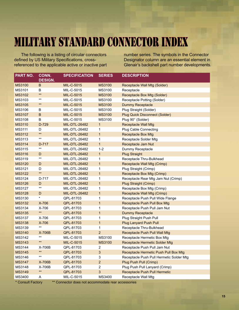
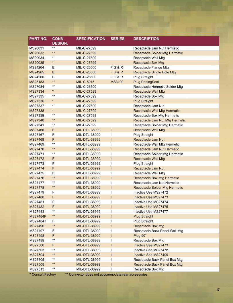
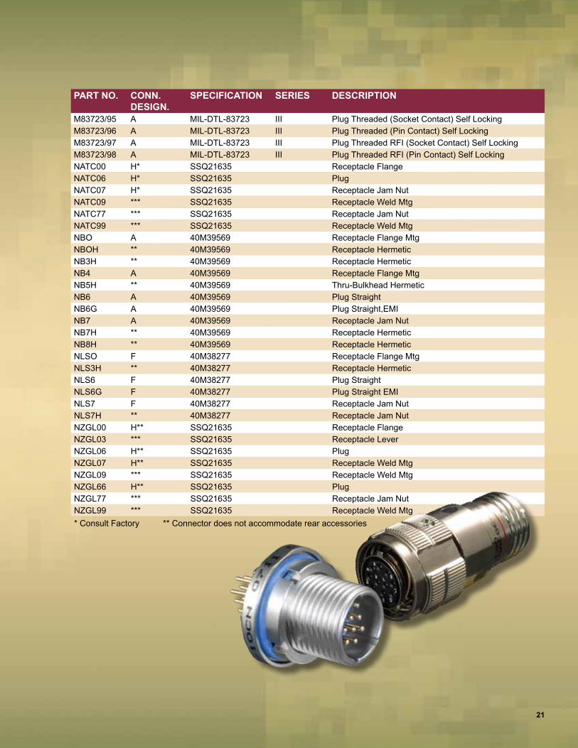
The following is a listing of circular connectors defined by US Military Specifications, cross-referenced to the applicable active or inactive part
number series. The symbols in the Connector Designator column are an essential element in Glenair’s backshell part number developments.
Military Standard connector indexMilitary Standard connector index
PART NO. CONN. DESIGN.
SPECIFICATION SERIES DESCRIPTION
MS3100 B MIL-C-5015 MS3100 Receptacle Wall Mtg (Solder)MS3101 B MIL-C-5015 MS3100 ReceptacleMS3102 ** MIL-C-5015 MS3100 Receptacle Box Mtg (Solder)MS3103 ** MIL-C-5015 MS3100 Receptacle Potting (Solder)MS3105 ** MIL-C-5015 MS3100 Dummy ReceptacleMS3106 B MIL-C-5015 MS3100 Plug Straight (Solder)MS3107 B MIL-C-5015 MS3100 Plug Quick Disconnect (Solder)MS3108 B MIL-C-5015 MS3100 Plug 90° (Solder)MS3110 D-729 MIL-DTL-26482 1 Receptacle Wall MtgMS3111 D MIL-DTL-26482 1 Plug Cable ConnectingMS3112 ** MIL-DTL-26482 1 Receptacle Box MtgMS3113 ** MIL-DTL-26482 1 Receptacle Solder MtgMS3114 D-717 MIL-DTL-26482 1 Receptacle Jam NutMS3115 ** MIL-DTL-26482 1-2 Dummy ReceptacleMS3116 D MIL-DTL-26482 1 Plug StraightMS3119 ** MIL-DTL-26482 1 Receptacle Thru-BulkheadMS3120 D MIL-DTL-26482 1 Receptacle Wall Mtg (Crimp)MS3121 D MIL-DTL-26482 1 Plug Straight (Crimp)MS3122 ** MIL-DTL-26482 1 Receptacle Box Mtg (Crimp)MS3124 D-717 MIL-DTL-26482 1 Receptacle Rear Mtg Jam Nut (Crimp)MS3126 D MIL-DTL-26482 1 Plug Straight (Crimp)MS3127 ** MIL-DTL-26482 1 Receptacle Box Mtg (Crimp)MS3128 D MIL-DTL-26482 1 Receptacle Wall Mtg (Crimp)MS3130 * QPL-81703 1 Receptacle Push Pull Wide FlangeMS3132 X-706 QPL-81703 1 Receptacle Push Pull Box MtgMS3134 X-706 QPL-81703 1 Receptacle Push Pull Jam NutMS3135 ** QPL-81703 1 Dummy ReceptacleMS3137 X-706 QPL-81703 1 Plug Straight Push PullMS3138 X-706 QPL-81703 1 Plug Lanyard Push PullMS3139 ** QPL-81703 1 Receptacle Thru-BulkheadMS3140 X-706B QPL-81703 2 Receptacle Push Pull Wall MtgMS3142 ** MIL-C-5015 MS3100 Receptacle Hermetic Box MtgMS3143 ** MIL-C-5015 MS3100 Receptacle Hermetic Solder MtgMS3144 X-706B QPL-81703 2 Receptacle Push Pull Jam NutMS3145 ** QPL-81703 3 Receptacle Hermetic Push Pull Box MtgMS3146 ** QPL-81703 3 Receptacle Push Pull Hermetic Solder MtgMS3147 X-706B QPL-81703 2 Plug Push Pull (Crimp)MS3148 X-706B QPL-81703 2 Plug Push Pull Lanyard (Crimp)MS3149 ** QPL-81703 3 Receptacle Push Pull HermeticMS3400 A MIL-C-5015 MS3400 Receptacle Wall Mtg* Consult Factory ** Connector does not accommodate rear accessories
15

PART NO. CONN. DESIGN.
SPECIFICATION SERIES DESCRIPTION
MS3401 A MIL-C-5015 MS3400 Receptacle Cable ConnectingMS3402 ** MIL-C-5015 MS3400 Receptacle,Box MtgMS3404 A MIL-C-5015 MS3400 Receptacle Jam NutMS3406 A MIL-C-5015 MS3400 PlugMS3408 A MIL-C-5015 MS3400 Plug 90°MS3409 A MIL-C-5015 MS3400 Plug 45°MS3412 A MIL-C-5015 MS3400 Receptacle Wall MtgMS3424 A QPL-81703 3 Receptacle Push Pull Wall MtgMS3440 ** MIL-DTL-26482 2 Receptacle Narrow Flange Mtg (was M83723/9/10)MS3442 ** MIL-DTL-26482 2 Receptacle Wide Flange MtgMS3443 ** MIL-DTL-26482 2 Receptacle Solder Flange MtgMS3445 * QPL-81703 2 Plug Push Pull Rack & Panel MtgMS3446 A QPL-81703 3 Plug Rack & PanelMS3449 ** MIL-DTL-26482 2 Receptacle Single Hole MtgMS3450 A MIL-C-5015 MS3450 Receptacle Wall Mtg (was M83723/19/20)MS3451 A MIL-C-5015 MS3450 Receptacle Cable Connecting (was M83723/17/18)MS3452 ** MIL-C-5015 MS3450 Receptacle Box Mtg (was M83723/21/22)MS3454 A MIL-C-5015 MS3450 Receptacle Jam NutMS3456 A MIL-C-5015 MS3450 Plug Straight (was M83723/23/24)MS3459 A MIL-C-5015 MS3450 Plug Straight Self Locking (was M83723/52/53)MS3463 ** QPL-81703 3 Receptacle Push PullMS3464 A QPL-81703 3 Receptacle Push Pull Jam NutMS3466 ** QPL-81703 3 Receptacle Push Pull HermeticMS3467 A QPL-81703 3 Plug Push PullMS3468 A QPL-81703 3 Plug Push Pull LanyardMS3469 ** QPL-81703 3 Receptacle Push Pull Hermetic Jam NutMS3470 A MIL-DTL-26482 2 Receptacle Narrow Flange Mtg (was M83723/1/2)MS3471 A MIL-DTL-26482 2 Receptacle Cable Connecting (was M83723/7/8)MS3472 A MIL-DTL-26482 2 Receptacle Wide Flange Mtg (was M83723/3/4)MS3473 ** MIL-DTL-26482 2 Receptacle Solder Mtg HermeticMS3474 A MIL-DTL-26482 2 Receptacle Rear Mtg Jam Nut (was M83723/5/6)MS3475 A MIL-DTL-26482 2 Plug RFI Shielded (was M83723/42/43)MS3476 A MIL-DTL-26482 2 Plug Straight (was M83723/13/14)MS3477 ** MIL-DTL-26482 2 Receptacle Hermetic Box MtgMS3479 ** MIL-DTL-26482 2 Receptacle Hermetic Rear Mtg Jam NutMS17343 C MIL-DTL-22992 R Receptacle Wall MtgMS17344 C MIL-DTL-22992 R Plug StraightMS17345 C MIL-DTL-22992 R Plug Cable ConnectingMS17346 C MIL-DTL-22992 R Receptacle Box MtgMS17347 C MIL-DTL-22992 R Receptacle Jam NutMS17348 ** MIL-DTL-22992 R Receptacle Jam Nut Box MtgMS18062 ** MIL-DTL-22992 R Dummy ReceptacleMS20026 * MIL-C-27599 Receptacle Wall Mtg SolderMS20027 * MIL-C-27599 Receptacle LineMS20028 * MIL-C-27599 Plug StraightMS20029 ** MIL-C-27599 Receptacle Jam Nut MtgMS20030 * MIL-C-27599 Receptacle Box Mtg Hermetic* Consult Factory ** Connector does not accommodate rear accessories
Military Standard Connector Index
16
PART NO. CONN. DESIGN.
SPECIFICATION SERIES DESCRIPTION
MS20031 ** MIL-C-27599 Receptacle Jam Nut HermeticMS20032 ** MIL-C-27599 Receptacle Solder Mtg HermeticMS20034 * MIL-C-27599 Receptacle Wall MtgMS20035 * MIL-C-27599 Receptacle Box MtgMS24264 E MIL-C-26500 F G & R Receptacle Flange MtgMS24265 E MIL-C-26500 F G & R Receptacle Single Hole MtgMS24266 E MIL-C-26500 F G & R Plug StraightMS25183 ** MIL-C-5015 MS3100 Plug PottingSealMS27034 ** MIL-C-26500 Receptacle Hermetic Solder MtgMS27334 * MIL-C-27599 Receptacle Wall MtgMS27335 ** MIL-C-27599 Receptacle Box MtgMS27336 * MIL-C-27599 Plug StraightMS27337 * MIL-C-27599 Receptacle Jam NutMS27338 * MIL-C-27599 Receptacle Wall Mtg HermeticMS27339 ** MIL-C-27599 Receptacle Box Mtg HermeticMS27340 ** MIL-C-27599 Receptacle Jam Nut Mtg HermeticMS27341 ** MIL-C-27599 Receptacle Solder Mtg HermeticMS27466 F MIL-DTL-38999 I Receptacle Wall MtgMS27467 F MIL-DTL-38999 I Plug StraightMS27468 F MIL-DTL-38999 I Receptacle Jam NutMS27469 ** MIL-DTL-38999 I Receptacle Wall Mtg HermeticMS27470 ** MIL-DTL-38999 I Receptacle Jam Nut HermeticMS27471 ** MIL-DTL-38999 I Receptacle Solder Mtg HermeticMS27472 F MIL-DTL-38999 II Receptacle Wall MtgMS27473 F MIL-DTL-38999 II Plug StraightMS27474 F MIL-DTL-38999 II Receptacle Jam NutMS27475 F MIL-DTL-38999 II Receptacle Wall MtgMS27476 ** MIL-DTL-38999 II Receptacle Box Mtg HermeticMS27477 ** MIL-DTL-38999 II Receptacle Jam Nut HermeticMS27478 ** MIL-DTL-38999 II Receptacle Solder Mtg HermeticMS27479 F MIL-DTL-38999 II Inactive Use MS27472MS27480 F MIL-DTL-38999 II Inactive Use MS27473MS27481 F MIL-DTL-38999 II Inactive Use MS27474MS27482 F MIL-DTL-38999 II Inactive Use MS27475MS27483 ** MIL-DTL-38999 II Inactive Use MS27477MS27484P ** MIL-DTL-38999 II Plug StraightMS27484T F MIL-DTL-38999 II Plug StraightMS27496 ** MIL-DTL-38999 I Receptacle Box MtgMS27497 F MIL-DTL-38999 II Receptacle Back Panel Wall MtgMS27498 F MIL-DTL-38999 I Plug 90°MS27499 ** MIL-DTL-38999 II Receptacle Box MtgMS27500 F MIL-DTL-38999 II Inactive See MS27473MS27503 ** MIL-DTL-38999 II Inactive See MS27478MS27504 ** MIL-DTL-38999 II Inactive See MS27499MS27505 ** MIL-DTL-38999 I Receptacle Back Panel Box MtgMS27508 ** MIL-DTL-38999 II Receptacle Back Panel Box MtgMS27513 ** MIL-DTL-38999 II Receptacle Box Mtg* Consult Factory ** Connector does not accommodate rear accessories
17

PART NO. CONN. DESIGN.
SPECIFICATION SERIES DESCRIPTION
MS27515 F MIL-DTL-38999 I Inactive Use MS27656MS27613 E-710 MIL-C-26500K Receptacle Panel MtgMS27614 E-710 MIL-C-26500K Receptacle D-Hole MtgMS27615 E-710 MIL-C-26500K Plug StraightMS27652 F MIL-DTL-38999 I Inactive Use MS27466MS27653 F MIL-DTL-38999 I Inactive Use MS27467MS27654 F MIL-DTL-38999 I Inactive Use MS27656MS27656 F MIL-DTL-38999 I Receptacle Back Panel Wall MtgMS27661 F-752 MIL-DTL-38999 I Plug Lanyard ReleaseMS27662 ** MIL-DTL-38999 I Receptacle Thru-BulkheadMS27664 ** MIL-DTL-38999 II Receptacle Back-Panel Wall MtgMS27665 F MIL-DTL-38999 I Plug Rack & Panel MtgMS27667 ** MIL-DTL-38999 II Receptacle Thru-BulkheadMS90555 * MIL-DTL-22992 L Receptacle Wall MtgMS90556 * MIL-DTL-22992 L Plug StraightMS90557 * MIL-DTL-22992 L Plug Cable ConnectingMS90558 * MIL-DTL-22992 L Receptacle W/Coupling Ring Wall MtgM28840/10 G MIL-DTL-28840 Receptacle Wall MtgM28840/11 G MIL-DTL-28840 Receptacle Cable ConnectingM28840/12 ** MIL-DTL-28840 Receptacle Box MtgM28840/14 G MIL-DTL-28840 Receptacle Jam NutM28840/16 G MIL-DTL-28840 Plug StraightD38999/20 H MIL-DTL-38999 III Receptacle Wall MtgD38999/21 ** MIL-DTL-38999 III Receptacle HermeticD38999/23 ** MIL-DTL-38999 III Receptacle Hermetic Jam NutD38999/24 H MIL-DTL-38999 III Receptacle Jam NutD38999/25 ** MIL-DTL-38999 III Receptacle Hermetic Solder MtgD38999/26 H MIL-DTL-38999 III Plug StraightD38999/27 ** MIL-DTL-38999 III Receptacle Hermetic Weld MtgD38999/29 H-701 MIL-DTL-38999 III Plug Lanyard ReleaseD38999/30 H-701 MIL-DTL-38999 III Plug Lanyard ReleaseD38999/40 H MIL-DTL-38999 IV Receptacle Wall MtgD38999/42 H MIL-DTL-38999 IV Receptacle Box MtgD38999/44 H-715 MIL-DTL-38999 IV Receptacle Jam NutD38999/46 H MIL-DTL-38999 IV Plug Straight EMID38999/47 H MIL-DTL-38999 IV Plug StraightM81511/1 J MIL-C-81511 2 Receptacle Flange MtgM81511/2 ** MIL-C-81511 2 Receptacle Solder FlangeM81511/3 J MIL-C-81511 2 Receptacle Jam NutM81511/4 ** MIL-C-81511 2 Receptacle Jam NutM81511/5 J MIL-C-81511 2 Plug Cable ConnectingM81511/6 J MIL-C-81511 2 PlugM81511/21 J MIL-C-81511 1 Receptacle Flange MtgM81511/22 ** MIL-C-81511 1 Receptacle Solder Flange MtgM81511/23 J MIL-C-81511 1 Receptacle Jam NutM81511/24 ** MIL-C-81511 1 Receptacle Jam NutM81511/25 J MIL-C-81511 1 Receptacle Cable Connecting* Consult Factory ** Connector does not accommodate rear accessories
Military Standard Connector Index
18

PART NO. CONN. DESIGN.
SPECIFICATION SERIES DESCRIPTION
M81511/26 J MIL-C-81511 1 PlugM81511/27 ** MIL-C-81511 1 Receptacle Thru-Bulkhead Jam NutM81511/28 ** MIL-C-81511 2 Receptacle Thru-Bulkhead Single Hole MtgM81511/31 J MIL-C-81511 2 Receptacle Flange MtgM81511/32 J MIL-C-81511 2 Receptacle Jam Nut MtgM81511/33 J MIL-C-81511 2 Recepacle,Cable ConnectingM81511/34 J MIL-C-81511 2 PlugM81511/35 J MIL-C-81511 1 Receptacle Flange MtgM81511/36 J MIL-C-81511 1 Receptacle Jam NutM81511/37 J MIL-C-81511 1 Receptacle Cable ConnectingM81511/38 J MIL-C-81511 1 PlugM81511/41 J MIL-C-81511 3 Receptacle Flange MtgM81511/42 ** MIL-C-81511 3 Receptacle Solder Flange MtgM81511/44 ** MIL-C-81511 3 Receptacle Jam NutM81511/45 J MIL-C-81511 3 Receptacle Cable ConnectingM81511/46 J MIL-C-81511 3 PlugM81511/47 ** MIL-C-81511 3 Receptacle Solder Flange MtgM81511/48 ** MIL-C-81511 3 Receptacle Jam NutM81511/49 J MIL-C-81511 3 Receptacle Jam NutM81511/50 ** MIL-C-81511 4 Receptacle Jam NutM81511/51 J MIL-C-81511 4 Receptacle Flange MtgM81511/52 ** MIL-C-81511 4 Receptacle Solder Flange MtgM81511/53 J MIL-C-81511 4 Receptacle Jam NutM81511/54 ** MIL-C-81511 4 Receptacle Jam NutM81511/55 J MIL-C-81511 4 Receptacle Cable ConnectingM81511/56 J MIL-C-81511 4 PlugM81511/57 ** MIL-C-81511 4 Receptacle Solder Flange MtgM81582/1 * MIL-C-81582 Receptacle Single Hole MtgM81582/2 * MIL-C-81582 Plug Lanyard ReleaseM83723/1 A MIL-DTL-83723 I Superseded by MS3470M83723/2 A MIL-DTL-83723 I Superseded by MS3470M83723/3 A MIL-DTL-83723 I Superseded by MS3472M83723/4 A MIL-DTL-83723 I Superseded by MS3472M83723/5 A MIL-DTL-83723 I Superseded by MS3474M83723/6 A MIL-DTL-83723 I Superseded by MS3474M83723/7 A MIL-DTL-83723 I Superseded by MS3471M83723/8 A MIL-DTL-83723 I Superseded by MS3471M83723/9 ** MIL-DTL-83723 I Superseded by MS3440M83723/10 ** MIL-DTL-83723 I Superseded by MS3442M83723/11 ** MIL-DTL-83723 I Superseded by MS3443M83723/12 ** MIL-DTL-83723 I Superseded by MS3443M83723/13 A MIL-DTL-83723 I Superseded by MS3476M83723/14 A MIL-DTL-83723 I Superseded by MS3476M83723/17 K MIL-DTL-83723 II Superseded by MS3451M83723/18 K MIL-DTL-83723 II Superseded by MS3451M83723/19 K MIL-DTL-83723 II Superseded by MS3450M83723/20 K MIL-DTL-83723 II Superseded by MS3450* Consult Factory ** Connector does not accommodate rear accessories
19

PART NO. CONN. DESIGN.
SPECIFICATION SERIES DESCRIPTION
M83723/21 ** MIL-DTL-83723 II Superseded by MS3452M83723/22 ** MIL-DTL-83723 II Superseded by MS3452M83723/23 K MIL-DTL-83723 II Superseded by MS3456M83723/24 K MIL-DTL-83723 II Superseded by MS3456M83723/25 ** MIL-DTL-83723 II Superseded by MS3142M83723/26 ** MIL-DTL-83723 II Superseded by MS3143M83723/36 A MIL-DTL-83723 I Inactive For New DesignM83723/37 A MIL-DTL-83723 I Inactive For New DesignM83723/38 A MIL-DTL-83723 I Inactive For New DesignM83723/39 A MIL-DTL-83723 I Inactive For New DesignM83723/40 A MIL-DTL-83723 I Inactive For New DesignM83723/41 A MIL-DTL-83723 I Inactive For New DesignM83723/42 A MIL-DTL-83723 I Superseded by MS3475M83723/43 A MIL-DTL-83723 I Superseded by MS3475M83723/45 ** MIL-DTL-83723 I Superseded by MS3115M83723/48 A MIL-DTL-83723 I Inactive For New DesignM83723/49 A MIL-DTL-83723 I Inactive For New DesignM83723/52 K MIL-DTL-83723 II Superseded by MS3459M83723/53 K MIL-DTL-83723 II Superseded by MS3459M83723/66 A MIL-DTL-83723 III Plug Push Pull (Pin Contacts)M83723/67 A MIL-DTL-83723 III Plug Push Pull (Socket Contacts)M83723/68 A MIL-DTL-83723 III Plug Push Pull Lanyard (Pin Contacts)M83723/69 A MIL-DTL-83723 III Plug Push Pull Lanyard (Socket Contacts)M83723/71 A MIL-DTL-83723 III Receptacle Bayonet Flange Mtg (Socket Contact)M83723/72 A MIL-DTL-83723 III Receptacle Bayonet Flange Mtg (Pin Contact)M83723/73 A MIL-DTL-83723 III Receptacle Bayonet Single Hole Mtg (Socket Contact)M83723/74 A MIL-DTL-83723 III Receptacle Bayonet Single Mtg (Pin Contact)M83723/75 A MIL-DTL-83723 III Plug Bayonet (Socket Contact)M83723/76 A MIL-DTL-83723 III Plug Bayonet (Pin Contact)M83723/77 A MIL-DTL-83723 III Plug Bayonet RFI (Socket Contact)M83723/78 A MIL-DTL-83723 III Plug Bayonet RFI (Pin Contact)M83723/79 ** MIL-DTL-83723 III Receptacle Bayonet Flange Mtg HermeticM83723/80 ** MIL-DTL-83723 III Receptacle Bayonet Solder Flange Mtg HermeticM83723/81 ** MIL-DTL-83723 III Receptacle Bayonet Single Hole Mtg HermeticM83723/82 A MIL-DTL-83723 III Receptacle Threaded Flange Mtg (Socket Contact)M83723/83 A MIL-DTL-83723 III Receptacle Threaded Flange Mtg (Pin Contact)M83723/84 A MIL-DTL-83723 III Receptacle Threaded Single Hole Mtg (Socket Contact)M83723/85 A MIL-DTL-83723 III Receptacle Threaded Single Hole Mtg (Pin Contact)M83723/86 A MIL-DTL-83723 III Plug Threaded (Socket Contact)M83723/87 A MIL-DTL-83723 III Plug Threaded (Pin Contact)M83723/88 ** MIL-DTL-83723 III Receptacle Threaded Flange Mtg (Pin Contact)M83723/89 ** MIL-DTL-83723 III Receptacle Threaded Single Hole Mtg HermeticM83723/90 ** MIL-DTL-83723 III Receptacle Threaded Solder Flange Mtg HermeticM83723/91 A MIL-DTL-83723 III Plug Threaded RFI (Socket Contact)M83723/92 A MIL-DTL-83723 III Plug Threaded RFI (Pin Contact)M83723/93 ** MIL-DTL-83723 III Receptacle Bayonet Solder Flange Mtg HermeticM83723/94 ** MIL-DTL-83723 III Receptacle Bayonet Single Hole Mtg Hermetic* Consult Factory ** Connector does not accommodate rear accessories
Military Standard Connector Index
20
PART NO. CONN. DESIGN.
SPECIFICATION SERIES DESCRIPTION
M83723/95 A MIL-DTL-83723 III Plug Threaded (Socket Contact) Self LockingM83723/96 A MIL-DTL-83723 III Plug Threaded (Pin Contact) Self LockingM83723/97 A MIL-DTL-83723 III Plug Threaded RFI (Socket Contact) Self LockingM83723/98 A MIL-DTL-83723 III Plug Threaded RFI (Pin Contact) Self LockingNATC00 H* SSQ21635 Receptacle FlangeNATC06 H* SSQ21635 PlugNATC07 H* SSQ21635 Receptacle Jam NutNATC09 *** SSQ21635 Receptacle Weld MtgNATC77 *** SSQ21635 Receptacle Jam NutNATC99 *** SSQ21635 Receptacle Weld MtgNBO A 40M39569 Receptacle Flange MtgNBOH ** 40M39569 Receptacle HermeticNB3H ** 40M39569 Receptacle HermeticNB4 A 40M39569 Receptacle Flange MtgNB5H ** 40M39569 Thru-Bulkhead HermeticNB6 A 40M39569 Plug StraightNB6G A 40M39569 Plug Straight,EMINB7 A 40M39569 Receptacle Jam NutNB7H ** 40M39569 Receptacle HermeticNB8H ** 40M39569 Receptacle HermeticNLSO F 40M38277 Receptacle Flange MtgNLS3H ** 40M38277 Receptacle HermeticNLS6 F 40M38277 Plug StraightNLS6G F 40M38277 Plug Straight EMINLS7 F 40M38277 Receptacle Jam NutNLS7H ** 40M38277 Receptacle Jam NutNZGL00 H** SSQ21635 Receptacle FlangeNZGL03 *** SSQ21635 Receptacle LeverNZGL06 H** SSQ21635 PlugNZGL07 H** SSQ21635 Receptacle Weld MtgNZGL09 *** SSQ21635 Receptacle Weld MtgNZGL66 H** SSQ21635 PlugNZGL77 *** SSQ21635 Receptacle Jam NutNZGL99 *** SSQ21635 Receptacle Weld Mtg* Consult Factory ** Connector does not accommodate rear accessories
21

22
MILITARY SPECIFICATION
ENVIRONMENTAL AND MATERIAL
CLASS
PERFORMANCE CONTACT TYPE SHELL
DESCRIPTION FLUID RESISTANCE RESILIENT MATERIAL OPERATING
TEMP SOLDERCRIMP
SIZE SHELL MATERIAL FINISH DESCRIPTION COUPLING TYPE
FRONT REAR
MIL-C-5015 Solder Section 1B
A Non-Environmental Solid Shell Moisture-proof – 125°C • – –
16 12 8 4
1/0
Aluminum 96 hr. Cad O.D.
Threaded
B Non-Environmental Split Shell Moisture-proof – 125° C • – – Aluminum 96 hr. Cad O.D.C Pressurized Moisture-proof – 125°C • – – Aluminum 96 hr. Cad O.D.E Environmental Grommet Seal Moisture-proof Neoprene 125°C • – – Aluminum 96 hr. Cad O.D.F Environmental Grommet Seal with Clamp Moisture-proof Neoprene 125°C • – – Aluminum 96 hr. Cad O.D.
HS Hermetic Submersible Silicone 125°C • – – Stainless Steel 96 hr. Cad O.D.HT Hermetic Submersible Complete 125°C • – – Carbon Steel TInnedK Non-Environmental Firewall Moisture-proof – 125°C Non-Removable Crimp Carbon Steel 96 hr. Cad O.D.R Environmental Grommet Seal with ‘O’ Ring Moisture-proof Neoprene 125°C • – – Aluminum 96 hr. Cad O.D.
MIL-C 5015 Crimp Front Release Per
MIL-STD-242 MIL-STD-1353 MIL-STD-1683
Section 1C
D Environmental High Shock Splash-proof Silicone 175°C – • –
16 12 8 4
1/0
Aluminum 500 hr. Cad O.D.
Threaded
DJ Environmental High Shock Splash-proof Silicone 175°C – • – Aluminum 500 hr. Cad O.D.DJS Environmental High Shock Splash-proof Silicone 175°C – • – Stainless Steel Black CadDS Environmental High Shock Splash-proof Silicone 175°C – • – Stainless Steel Black CadK Environmental Firewall Submersible Silicone 175°C – • – Carbon Steel Electroless Nickel
KS Environmental Firewall Submersible Silicone 175°C – • – Stainless Steel PassivatedKT Environmental Firewall Submersible Silicone 175°C – • – Carbon Steel 96 hr. Cad O.D.L Environmental High Temperature Submersible Silicone 200°C – • – Aluminum Electroless Nickel
LS Environmental High Temperature Submersible Silicone 200°C – • – Stainless Steel PassivatedU Environmental High Temperature Splash-proof Silicone 200°C – • – Aluminum Electroless Nickel
US Environmental High Temperature Splash-proof Silicone 200°C – • – Stainless Steel PassivatedW Environmental General Purpose Splash-proof Silicone 175°C – • – Aluminum 96 hr. Cad O.D.
MIL-C-5015 Crimp Rear Release Per
MIL-STD-242 MIL-STD-975 MIL-STD-1353
MIL-STD-1547 (8, 4 & 0 Contacts Only)
Section 1D
K Environmental Firewall Submersible Silicone 175°C – – •
16 12 8 4
1/0
Carbon Steel Electroless Nickel
Threaded
KS Environmental Firewall Submersible Silicone 175°C – – • Stainless PassivatedKT Environmental Firewall Submersible Silicone 175°C – – • Carbon Steel 96 hr. Cad O.D.L Environmental High Temperature Submersible Silicone 200°C – – • Aluminum Electroless Nickel
LS Environmental High Temperature Submersible Silicone 200°C – – • Stainless Steel PassivatedU Environmental High Temperature Splash-proof Silicone 200°C – – • Aluminum Electroless Nickel
US Environmental High Temperature Splash-proof Silicone 200°C – – • Stainless Steel PassivatedW Environmental General Purpose Splash-proof Silicone 175°C – – • Aluminum 96 hr. Cad O.D.
MIL-C-10544 Section 2 ALL Environmental Signal Corps Audio U Series Moisture-proof Neoprene 125°C Solder & Taper Pin Terminations 16 Stainless Steel Passivated Reverse Bayonet
MIL-C-12520 Section 3 ALL Environmental Signal Corps Power UW
Series Moisture-proof Neoprene 125°C • – –
20 16 12 8
Aluminum Cad O.D. Center Lock Screw
MIL-C-22249 Section 4 ALL Environmental High Pressure Bulkhead Submersible Silicone 73°C • – – 20
16 Stainless Steel Passivated Threaded
MIL-C-22539 Section 5 ALL Environmental High Pressure Bulkhead Submersible Dially Phthalate 73°C • – – 16
12 Stainless Steel Passivated Threaded
Military Specification Comparison Tables

23
MILITARY SPECIFICATION
ENVIRONMENTAL AND MATERIAL
CLASS
PERFORMANCE CONTACT TYPE SHELL
DESCRIPTION FLUID RESISTANCE RESILIENT MATERIAL OPERATING
TEMP SOLDERCRIMP
SIZE SHELL MATERIAL FINISH DESCRIPTION COUPLING TYPE
FRONT REAR
MIL-C-5015 Solder Section 1B
A Non-Environmental Solid Shell Moisture-proof – 125°C • – –
16 12 8 4
1/0
Aluminum 96 hr. Cad O.D.
Threaded
B Non-Environmental Split Shell Moisture-proof – 125° C • – – Aluminum 96 hr. Cad O.D.C Pressurized Moisture-proof – 125°C • – – Aluminum 96 hr. Cad O.D.E Environmental Grommet Seal Moisture-proof Neoprene 125°C • – – Aluminum 96 hr. Cad O.D.F Environmental Grommet Seal with Clamp Moisture-proof Neoprene 125°C • – – Aluminum 96 hr. Cad O.D.
HS Hermetic Submersible Silicone 125°C • – – Stainless Steel 96 hr. Cad O.D.HT Hermetic Submersible Complete 125°C • – – Carbon Steel TInnedK Non-Environmental Firewall Moisture-proof – 125°C Non-Removable Crimp Carbon Steel 96 hr. Cad O.D.R Environmental Grommet Seal with ‘O’ Ring Moisture-proof Neoprene 125°C • – – Aluminum 96 hr. Cad O.D.
MIL-C 5015 Crimp Front Release Per
MIL-STD-242 MIL-STD-1353 MIL-STD-1683
Section 1C
D Environmental High Shock Splash-proof Silicone 175°C – • –
16 12 8 4
1/0
Aluminum 500 hr. Cad O.D.
Threaded
DJ Environmental High Shock Splash-proof Silicone 175°C – • – Aluminum 500 hr. Cad O.D.DJS Environmental High Shock Splash-proof Silicone 175°C – • – Stainless Steel Black CadDS Environmental High Shock Splash-proof Silicone 175°C – • – Stainless Steel Black CadK Environmental Firewall Submersible Silicone 175°C – • – Carbon Steel Electroless Nickel
KS Environmental Firewall Submersible Silicone 175°C – • – Stainless Steel PassivatedKT Environmental Firewall Submersible Silicone 175°C – • – Carbon Steel 96 hr. Cad O.D.L Environmental High Temperature Submersible Silicone 200°C – • – Aluminum Electroless Nickel
LS Environmental High Temperature Submersible Silicone 200°C – • – Stainless Steel PassivatedU Environmental High Temperature Splash-proof Silicone 200°C – • – Aluminum Electroless Nickel
US Environmental High Temperature Splash-proof Silicone 200°C – • – Stainless Steel PassivatedW Environmental General Purpose Splash-proof Silicone 175°C – • – Aluminum 96 hr. Cad O.D.
MIL-C-5015 Crimp Rear Release Per
MIL-STD-242 MIL-STD-975
MIL-STD-1353 MIL-STD-1547 (8, 4 &
0 Contacts Only)
Section 1D
K Environmental Firewall Submersible Silicone 175°C – – •
16 12 8 4
1/0
Carbon Steel Electroless Nickel
Threaded
KS Environmental Firewall Submersible Silicone 175°C – – • Stainless PassivatedKT Environmental Firewall Submersible Silicone 175°C – – • Carbon Steel 96 hr. Cad O.D.L Environmental High Temperature Submersible Silicone 200°C – – • Aluminum Electroless Nickel
LS Environmental High Temperature Submersible Silicone 200°C – – • Stainless Steel PassivatedU Environmental High Temperature Splash-proof Silicone 200°C – – • Aluminum Electroless Nickel
US Environmental High Temperature Splash-proof Silicone 200°C – – • Stainless Steel PassivatedW Environmental General Purpose Splash-proof Silicone 175°C – – • Aluminum 96 hr. Cad O.D.
MIL-C-10544 Section 2 ALL Environmental Signal Corps Audio U Series Moisture-proof Neoprene 125°C Solder & Taper Pin Terminations 16 Stainless Steel Passivated Reverse Bayonet
MIL-C-12520 Section 3 ALL Environmental Signal Corps Power UW
Series Moisture-proof Neoprene 125°C • – –
20 16 12 8
Aluminum Cad O.D. Center Lock Screw
MIL-C-22249 Section 4 ALL Environmental High Pressure Bulkhead Submersible Silicone 73°C • – – 20
16 Stainless Steel Passivated Threaded
MIL-C-22539 Section 5 ALL Environmental High Pressure Bulkhead Submersible Dially Phthalate 73°C • – – 16
12 Stainless Steel Passivated Threaded

24
MILITARY SPECIFICATION
ENVIRONMENTAL AND MATERIAL
CLASS
PERFORMANCE CONTACT TYPE SHELL
DESCRIPTION FLUID RESISTANCE RESILIENT MATERIAL OPERATING
TEMP SOLDERCRIMP
SIZE SHELL MATERIAL FINISH DESCRIPTION COUPLING TYPE
FRONT REAR
MIL-DTL-22992 Class C, J & R
Section 6B
C*C* Environmental Pressurized Moisture-proof Neoprene 125°C • – –16 12 8 4
1/0
Aluminum 500 hr Cad O.D
Threaded Double Start
C*N* Environmental Pressurized Moisture-proof Neoprene 125°C – – Aluminum Black Anodize J*C* Environmental Pressurized, with Grommet Moisture-proof Neoprene 125°C – – Aluminum 500 hr Cad O.D.J*N* Environmental Pressurized, with Grommet Moisture-proof Neoprene 125°C – – Aluminum Black AnodizeR*C* Environmental Moisture-proof Neoprene 125°C – – Aluminum 500 hr Cad O.D.R*N* Environmental Moisture-proof Neoprene 125°C – – Aluminum Black Anodize
MIL-DTL-22992 Class L
Section 6D
L (C) Environmental, Gland Seal Backshell Moisture-proof Neoprene 125°C •6 4 2
1/0 4/0
Aluminum 500 hr Cad O.D.
L (N) Environmental, Gland Seal Backshell Moisture-proof Neoprene 125°C • Aluminum Black Anodize
MIL-C-24217 Section 7 ALL High Pressure Bulkhead Submersible Silicone 75C • – –
16 12 8 4
1/0
Stainless Steel Passivated Coupling
MIL-C-25955 Section 8
– Environmental Moisture-proof Neoprene 125°C – • –20
Aluminum Cadmium Threaded Double Start– Hermetic Moisture-proof Neoprene 125°C • – – Carbon Steel Tinned
MIL-DTL-26482 Series 1 Solder
Section 9B
A Non-Environmental Solid Shell Moisture-proof Neoprene 125°C • – –
20 16 12
Aluminum 96 hr Cad O.D.
Bayonet
B Non-Environmental with Strain Relief Moisture-proof Neoprene 125°C • – – Aluminum 96 hr Cad O.D.E Environmental with Grommet Nut Moisture-proof Neoprene 125°C • – – Aluminum 96 hr Cad O.D.F Environmental with Strain Relief Moisture-proof Neoprene 125°C • – – Aluminum 96 hr Cad O.D.
H*A* Hermetic Moisture-proof 125°C • Stainless Steel PassivateH*B* Hermetic Moisture-proof 125°C • Stainless Steel PassivateH*C* Hermetic Moisture-proof 125°C • Carbon Steel TinnedH*Y* Hermetic Moisture-proof 125°C • Carbon Steel Tinned
J Environmental Gland Seal Moisture-proof Neoprene 125°C • Aluminum 96 hr Cad O.D.P Environmental Potting Seal Moisture-proof Neoprene 125°C • Aluminum 96 hr Cad O.D.
MIL-DTL-26482 Series 1 Crimp
Section 9C
E Environmental with Grommet Nut Moisture-proof Neoprene 125°C – • – 20 16 12
Aluminum 96 hr Cad O.D.BayonetF Environmental with Strain Relief Moisture-proof Neoprene 125°C – • – Aluminum 96 hr Cad O.D.
P Environmental Potting Seal Moisture-proof Neoprene 125°C – • – Aluminum 96 hr Cad O.D.
MIL-DTL-26482
Series 2
A Environmental Submersible Silicone 175°C – – •
20 16 12
Aluminum Black Anodize
Bayonet
E Environmental Submersible Silicone 175°C Aluminum Electroless NickelH*A* Hermetic Submersible Silicone 200°C • – – Stainless Steel PassivateH*B* Hermetic Submersible Silicone 200°C • – – Stainless Steel PassivateH*C* Hermetic Submersible Silicone 175°C • – – Carbon Steel TinnedH*Y* Hermetic Submersible Silicone 175°C • – – Carbon Steel Tinned
L Environmental Submersible Silicone 200°C – – • Aluminum Electroless NickelN Hermetic Submersible Silicone 175°C – – • Carbon Steel TinnedS Environmental Submersible Silicone 200°C – – • Stainless Steel Electroless NickelW Environmental Submersible Silicone 175°C – – • Aluminum 500 hr Cad O.D.
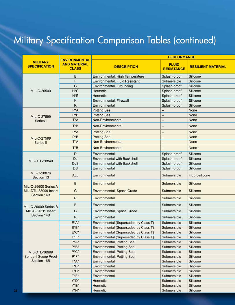
Military Specification Comparison Tables (continued)

25
MILITARY SPECIFICATION
ENVIRONMENTAL AND MATERIAL
CLASS
PERFORMANCE CONTACT TYPE SHELL
DESCRIPTION FLUID RESISTANCE RESILIENT MATERIAL OPERATING
TEMP SOLDERCRIMP
SIZE SHELL MATERIAL FINISH DESCRIPTION COUPLING TYPE
FRONT REAR
MIL-DTL-22992 Class C, J & R
Section 6B
C*C* Environmental Pressurized Moisture-proof Neoprene 125°C • – –16 12 8 4
1/0
Aluminum 500 hr Cad O.D
Threaded Double Start
C*N* Environmental Pressurized Moisture-proof Neoprene 125°C – – Aluminum Black Anodize J*C* Environmental Pressurized, with Grommet Moisture-proof Neoprene 125°C – – Aluminum 500 hr Cad O.D.J*N* Environmental Pressurized, with Grommet Moisture-proof Neoprene 125°C – – Aluminum Black AnodizeR*C* Environmental Moisture-proof Neoprene 125°C – – Aluminum 500 hr Cad O.D.R*N* Environmental Moisture-proof Neoprene 125°C – – Aluminum Black Anodize
MIL-DTL-22992 Class L
Section 6D
L (C) Environmental, Gland Seal Backshell Moisture-proof Neoprene 125°C •6 4 2
1/0 4/0
Aluminum 500 hr Cad O.D.
L (N) Environmental, Gland Seal Backshell Moisture-proof Neoprene 125°C • Aluminum Black Anodize
MIL-C-24217 Section 7 ALL High Pressure Bulkhead Submersible Silicone 75C • – –
16 12 8 4
1/0
Stainless Steel Passivated Coupling
MIL-C-25955 Section 8
– Environmental Moisture-proof Neoprene 125°C – • –20
Aluminum Cadmium Threaded Double Start– Hermetic Moisture-proof Neoprene 125°C • – – Carbon Steel Tinned
MIL-DTL-26482 Series 1 Solder
Section 9B
A Non-Environmental Solid Shell Moisture-proof Neoprene 125°C • – –
20 16 12
Aluminum 96 hr Cad O.D.
Bayonet
B Non-Environmental with Strain Relief Moisture-proof Neoprene 125°C • – – Aluminum 96 hr Cad O.D.E Environmental with Grommet Nut Moisture-proof Neoprene 125°C • – – Aluminum 96 hr Cad O.D.F Environmental with Strain Relief Moisture-proof Neoprene 125°C • – – Aluminum 96 hr Cad O.D.
H*A* Hermetic Moisture-proof 125°C • Stainless Steel PassivateH*B* Hermetic Moisture-proof 125°C • Stainless Steel PassivateH*C* Hermetic Moisture-proof 125°C • Carbon Steel TinnedH*Y* Hermetic Moisture-proof 125°C • Carbon Steel Tinned
J Environmental Gland Seal Moisture-proof Neoprene 125°C • Aluminum 96 hr Cad O.D.P Environmental Potting Seal Moisture-proof Neoprene 125°C • Aluminum 96 hr Cad O.D.
MIL-DTL-26482 Series 1 Crimp
Section 9C
E Environmental with Grommet Nut Moisture-proof Neoprene 125°C – • – 20 16 12
Aluminum 96 hr Cad O.D.BayonetF Environmental with Strain Relief Moisture-proof Neoprene 125°C – • – Aluminum 96 hr Cad O.D.
P Environmental Potting Seal Moisture-proof Neoprene 125°C – • – Aluminum 96 hr Cad O.D.
MIL-DTL-26482
Series 2
A Environmental Submersible Silicone 175°C – – •
20 16 12
Aluminum Black Anodize
Bayonet
E Environmental Submersible Silicone 175°C Aluminum Electroless NickelH*A* Hermetic Submersible Silicone 200°C • – – Stainless Steel PassivateH*B* Hermetic Submersible Silicone 200°C • – – Stainless Steel PassivateH*C* Hermetic Submersible Silicone 175°C • – – Carbon Steel TinnedH*Y* Hermetic Submersible Silicone 175°C • – – Carbon Steel Tinned
L Environmental Submersible Silicone 200°C – – • Aluminum Electroless NickelN Hermetic Submersible Silicone 175°C – – • Carbon Steel TinnedS Environmental Submersible Silicone 200°C – – • Stainless Steel Electroless NickelW Environmental Submersible Silicone 175°C – – • Aluminum 500 hr Cad O.D.
26
MILITARY SPECIFICATION
ENVIRONMENTAL AND MATERIAL
CLASS
PERFORMANCE CONTACT TYPE SHELL
DESCRIPTION FLUID RESISTANCE RESILIENT MATERIAL OPERATING
TEMP SOLDERCRIMP
SIZE SHELL MATERIAL FINISH DESCRIPTION COUPLING TYPE
FRONT REAR
MIL-C-26500
E Environmental, High Temperature Splash-proof Silicone 200°C – • –
20 16 12
Stainless Steel Passivate
Bayonet or Threaded
F Environmental, Fluid Resistant Submersible Silicone 175°C – • – Aluminum Anodic CoatingG Environmental, Grounding Splash-proof Silicone 200°C – • – Aluminum Electroless Nickel
H*C Hermetic Splash-proof Silicone 200°C • – – Carbon Steel TinnedH*E Hermetic Splash-proof Silicone 200°C • – – Carbon Steel TinnedK Environmental, FIrewall Splash-proof Silicone 200°C – • – Stainless Steel PassivateR Environmental Splash-proof Silicone 175°C – • – Aluminum Black Anodize
MIL-C-27599 Series I
P*A Potting Seal – None 150°C • 22M 22D 20 16 12
Aluminum Bright/Gold Cad over Nickel
BayonetP*B Potting Seal – None 150°C • Aluminum Bright/Gold Cad over NickelT*A Non-Environmental – None 175°C • Aluminum 500 hr Cad O.D.
T*B Non-Environmental – None 175°C • Aluminum 500 hr Cad O.D.
MIL-C-27599 Series II
P*A Potting Seal – None 150°C • 22M 22D 20 16 12
Aluminum Bright/Gold Cad over Nickel
BayonetP*B Potting Seal – None 150°C • Aluminum Bright/Gold Cad over NickelT*A Non-Environmental – None 175°C • Aluminum 500 hr Cad O.D.
T*B Non-Environmental – None 175°C • Aluminum 500 hr Cad O.D.
MIL-DTL-28840
D Environmental Splash-proof Silicone 175°C •
20
Aluminum 500 hr Cad O.D.Threaded Double
StartDJ Environmental with Backshell Splash-proof Silicone 175°C • Aluminum 500 hr Cad O.D.
DJS Environmental with Backshell Splash-proof Silicone 175°C • Stainless Steel Black CadmiumDS Environmental Splash-proof Silicone 175°C • Stainless Steel Black Cadmium
MIL-C-28876 Section 13 ALL Environmental Submersible Fluorosilicone 65C Fiber Optic – Aluminum 500 hr Cad O.D. Threaded
MIL-C-29600 Series A MIL-DTL-38999 Insert
Section 14B
E Environmental Submersible Silicone 175°C • 22D 22 20 16 12
Composite NoneThreaded Triple
StartG Environmental, Space Grade Submersible Silicone 175°C • Composite Tin
R Environmental Submersible Silicone 175°C • Composite Tin
MIL-C-29600 Series B MIL-C-81511 Insert
Section 14B
E Environmental Submersible Silicone 175°C • 23 20 16 12
Composite NoneThreaded Triple
StartG Environmental, Space Grade Submersible Silicone 175°C • Composite Tin
R Environmental Submersible Silicone 175°C • Composite Tin
MIL-DTL-38999 Series 1 Scoop Proof
Section 16B
E*A* Environmental (Superseded by Class T) Submersible Silicone 150°C •
22M 22D 22 20 16 12 10 8
Aluminum Bright/Gold Cad over Nickel
Bayonet
E*B* Environmental (Superseded by Class T) Submersible Silicone 175°C • Aluminum 500 hr Cad O.D.E*C* Environmental (Superseded by Class T) Submersible Silicone 200°C • Aluminum Black AnodizeE*F* Environmental (Superseded by Class T) Submersible Silicone 200°C • Aluminum Electroless NickelP*A* Environmental, Potting Seal Submersible Silicone 150°C • Aluminum Bright/Gold Cad over NickelP*B* Environmental, Potting Seal Submersible Silicone 175°C • Aluminum 500 hr Cad O.D.P*C* Environmental, Potting Seal Submersible Silicone 200°C • Aluminum Black AnodizeP*F* Environmental, Potting Seal Submersible Silicone 200°C • Aluminum Electroless NickelT*A* Environmental Submersible Silicone 150°C • Aluminum Bright/Gold Cad over NickelT*B* Environmental Submersible Silicone 175°C • Aluminum 500 hr Cad O.D.T*C* Environmental Submersible Silicone 200°C • Aluminum Black AnodizeT*F* Environmental Submersible Silicone 200°C • Aluminum Electroless NickelY*D* Hermetic Submersible Silicone 150°C
Solder cup or Eyelet
Carbon Steel Fused TinY*E* Hermetic Submersible Silicone 200°C Stainless Steel PassivatedY*N* Hermetic Submersible Silicone 200°C Stainless Steel Electro deposited Nickel
Military Specification Comparison Tables (continued)

27
MILITARY SPECIFICATION
ENVIRONMENTAL AND MATERIAL
CLASS
PERFORMANCE CONTACT TYPE SHELL
DESCRIPTION FLUID RESISTANCE RESILIENT MATERIAL OPERATING
TEMP SOLDERCRIMP
SIZE SHELL MATERIAL FINISH DESCRIPTION COUPLING TYPE
FRONT REAR
MIL-C-26500
E Environmental, High Temperature Splash-proof Silicone 200°C – • –
20 16 12
Stainless Steel Passivate
Bayonet or Threaded
F Environmental, Fluid Resistant Submersible Silicone 175°C – • – Aluminum Anodic CoatingG Environmental, Grounding Splash-proof Silicone 200°C – • – Aluminum Electroless Nickel
H*C Hermetic Splash-proof Silicone 200°C • – – Carbon Steel TinnedH*E Hermetic Splash-proof Silicone 200°C • – – Carbon Steel TinnedK Environmental, FIrewall Splash-proof Silicone 200°C – • – Stainless Steel PassivateR Environmental Splash-proof Silicone 175°C – • – Aluminum Black Anodize
MIL-C-27599 Series I
P*A Potting Seal – None 150°C • 22M 22D 20 16 12
Aluminum Bright/Gold Cad over Nickel
BayonetP*B Potting Seal – None 150°C • Aluminum Bright/Gold Cad over NickelT*A Non-Environmental – None 175°C • Aluminum 500 hr Cad O.D.
T*B Non-Environmental – None 175°C • Aluminum 500 hr Cad O.D.
MIL-C-27599 Series II
P*A Potting Seal – None 150°C • 22M 22D 20 16 12
Aluminum Bright/Gold Cad over Nickel
BayonetP*B Potting Seal – None 150°C • Aluminum Bright/Gold Cad over NickelT*A Non-Environmental – None 175°C • Aluminum 500 hr Cad O.D.
T*B Non-Environmental – None 175°C • Aluminum 500 hr Cad O.D.
MIL-DTL-28840
D Environmental Splash-proof Silicone 175°C •
20
Aluminum 500 hr Cad O.D.Threaded Double
StartDJ Environmental with Backshell Splash-proof Silicone 175°C • Aluminum 500 hr Cad O.D.
DJS Environmental with Backshell Splash-proof Silicone 175°C • Stainless Steel Black CadmiumDS Environmental Splash-proof Silicone 175°C • Stainless Steel Black Cadmium
MIL-C-28876 Section 13 ALL Environmental Submersible Fluorosilicone 65C Fiber Optic – Aluminum 500 hr Cad O.D. Threaded
MIL-C-29600 Series A MIL-DTL-38999 Insert
Section 14B
E Environmental Submersible Silicone 175°C • 22D 22 20 16 12
Composite NoneThreaded Triple
StartG Environmental, Space Grade Submersible Silicone 175°C • Composite Tin
R Environmental Submersible Silicone 175°C • Composite Tin
MIL-C-29600 Series B MIL-C-81511 Insert
Section 14B
E Environmental Submersible Silicone 175°C • 23 20 16 12
Composite NoneThreaded Triple
StartG Environmental, Space Grade Submersible Silicone 175°C • Composite Tin
R Environmental Submersible Silicone 175°C • Composite Tin
MIL-DTL-38999 Series 1 Scoop Proof
Section 16B
E*A* Environmental (Superseded by Class T) Submersible Silicone 150°C •
22M 22D 22 20 16 12 10 8
Aluminum Bright/Gold Cad over Nickel
Bayonet
E*B* Environmental (Superseded by Class T) Submersible Silicone 175°C • Aluminum 500 hr Cad O.D.E*C* Environmental (Superseded by Class T) Submersible Silicone 200°C • Aluminum Black AnodizeE*F* Environmental (Superseded by Class T) Submersible Silicone 200°C • Aluminum Electroless NickelP*A* Environmental, Potting Seal Submersible Silicone 150°C • Aluminum Bright/Gold Cad over NickelP*B* Environmental, Potting Seal Submersible Silicone 175°C • Aluminum 500 hr Cad O.D.P*C* Environmental, Potting Seal Submersible Silicone 200°C • Aluminum Black AnodizeP*F* Environmental, Potting Seal Submersible Silicone 200°C • Aluminum Electroless NickelT*A* Environmental Submersible Silicone 150°C • Aluminum Bright/Gold Cad over NickelT*B* Environmental Submersible Silicone 175°C • Aluminum 500 hr Cad O.D.T*C* Environmental Submersible Silicone 200°C • Aluminum Black AnodizeT*F* Environmental Submersible Silicone 200°C • Aluminum Electroless NickelY*D* Hermetic Submersible Silicone 150°C
Solder cup or Eyelet
Carbon Steel Fused TinY*E* Hermetic Submersible Silicone 200°C Stainless Steel PassivatedY*N* Hermetic Submersible Silicone 200°C Stainless Steel Electro deposited Nickel

28
MILITARY SPECIFICATION
ENVIRONMENTAL AND MATERIAL
CLASS
PERFORMANCE CONTACT TYPE SHELL
DESCRIPTION FLUID RESISTANCE RESILIENT MATERIAL OPERATING
TEMP SOLDERCRIMP
SIZE SHELL MATERIAL FINISH DESCRIPTION COUPLING TYPE
FRONT REAR
MIL-DTL-38999 Series II Low Profile
Section 16C
E*A* Environmental, with Gland Nut Submersible Silicone 150°C •
22M 22D 22 20 16 12
Aluminum Bright/Gold Cad over Nickel
Bayonet
E*B* Environmental, with Gland Nut Submersible Silicone 175°C • Aluminum 500 hr Cad O.D.E*C* Environmental, with Gland Nut Submersible Silicone 200°C • Aluminum Black AnodizeE*F* Environmental, with Gland Nut Submersible Silicone 200°C • Aluminum Electroless NickelP*A* Environmental, Potting Seal Submersible Silicone 150°C • Aluminum Bright/Gold Cad over NickelP*B* Environmental, Potting Seal Submersible Silicone 175°C • Aluminum 500 hr Cad ODP*C* Environmental, Potting Seal Submersible Silicone 200°C • Aluminum Black AnodizeP*F* Environmental, Potting Seal Submersible Silicone 200°C • Aluminum Electroless NickelT*A* Environmental Submersible Silicone 150°C • Aluminum Bright/Gold Cad over NickelT*B* Environmental Submersible Silicone 175°C • Aluminum 500 hr Cad O.D.T*C* Environmental Submersible Silicone 200°C • Aluminum Black AnodizeT*F* Environmental Submersible Silicone 200°C • Aluminum Electroless NickelY*D* Hermetic Submersible Silicone 150°C Carbon Steel Fused TinY*E* Hermetic Submersible Silicone 200°C Solder cup
or EyeletStainless Steel Passivated
Y*N* Hermetic Submersible Silicone 200°C Stainless Steel Electro deposited Nickel
MIL-DTL-38999 Series III Scoop Proof
Section 16D
C Environmental Submersible Silicone 200°C •
22M 22D 22 20 16 12 10 8
Aluminum Black Anodize
Threaded Triple Start
F Environmental Submersible Silicone 200°C • Aluminum Electroless NickelG Environmental, Space Grade Submersible Silicone 200°C • Aluminum Electroless NickelH Hermetic, Space Grade Submersible Silicone 200°C • Stainless Steel Electroless NickelJ Environmental Submersible Silicone 175°C • Composite 2000 hr Salt SprayK Environmental, Firewall Submersible Silicone 200°C • Stainless Steel PassivatedM Environmental Submersible Silicone 200°C • Composite Electroless NickelN Hermetic Submersible Silicone 200°C • Stainless Steel Electro deposited NickelS Environmental Submersible Silicone 200°C • Stainless Steel Electro deposited NickelW Environmental Submersible Silicone 175°C • Aluminum 500 hr Cad O.D.Y Hermetic Submersible Silicone 200°C • Stainless Steel Electroless Nickel
MIL-C-55116 Section 17 – Environmental, Cable Seal Splash-proof Neoprene 125°C • 20 Stainless Steel Passivated Reverse Bayonet
MIL-C-55181 Section 18 – Environmental, Cable Seal Splash-proof Neoprene 125°C • Carbon Steel 96 hr Cad O.D. Center Lock Screw
MIL-C-55243 Section 19 – Environmental, Cable Seal Splash-proof Neoprene 125°C • Aluminum 96 hr Cad O.D. Reverse Bayonet
MIL-C-81511 Series1 Gang Release* Superseded by
Series 3
Section 20B
A Environmental Submersible Silicone 200°C •
23 20 16 12
Aluminum Electroless Nickel
Bayonet
B Hermetic Submersible Silicone 200°C * Stainless Steel PassivatedC Environmental, Potting Seal Submersible Silicone 200°C • Aluminum Electroless NickelD Hermetic Submersible Silicone 175°C * Stainless Steel PassivatedE Environmental Splash-proof Silicone 150°C * Aluminum 96 hr Cad O.D.F Environmental Submersible Silicone 175°C • Aluminum Electroless NickelG Hermetic Submersible Silicone 175°C • Stainless Steel PassivatedH Hermetic Submersible Silicone 150°C * Carbon Steel TinnedP Environmental, Potting Seal Splash-proof Silicone 150°C • Aluminum 96 hr Cad O.D.T Environmental, Potting Seal Submersible Silicone 175°C * Aluminum Electroless Nickel
Military Specification Comparison Tables (continued)

29
MILITARY SPECIFICATION
ENVIRONMENTAL AND MATERIAL
CLASS
PERFORMANCE CONTACT TYPE SHELL
DESCRIPTION FLUID RESISTANCE RESILIENT MATERIAL OPERATING
TEMP SOLDERCRIMP
SIZE SHELL MATERIAL FINISH DESCRIPTION COUPLING TYPE
FRONT REAR
MIL-DTL-38999 Series II Low Profile
Section 16C
E*A* Environmental, with Gland Nut Submersible Silicone 150°C •
22M 22D 22 20 16 12
Aluminum Bright/Gold Cad over Nickel
Bayonet
E*B* Environmental, with Gland Nut Submersible Silicone 175°C • Aluminum 500 hr Cad O.D.E*C* Environmental, with Gland Nut Submersible Silicone 200°C • Aluminum Black AnodizeE*F* Environmental, with Gland Nut Submersible Silicone 200°C • Aluminum Electroless NickelP*A* Environmental, Potting Seal Submersible Silicone 150°C • Aluminum Bright/Gold Cad over NickelP*B* Environmental, Potting Seal Submersible Silicone 175°C • Aluminum 500 hr Cad ODP*C* Environmental, Potting Seal Submersible Silicone 200°C • Aluminum Black AnodizeP*F* Environmental, Potting Seal Submersible Silicone 200°C • Aluminum Electroless NickelT*A* Environmental Submersible Silicone 150°C • Aluminum Bright/Gold Cad over NickelT*B* Environmental Submersible Silicone 175°C • Aluminum 500 hr Cad O.D.T*C* Environmental Submersible Silicone 200°C • Aluminum Black AnodizeT*F* Environmental Submersible Silicone 200°C • Aluminum Electroless NickelY*D* Hermetic Submersible Silicone 150°C Carbon Steel Fused TinY*E* Hermetic Submersible Silicone 200°C Solder cup
or EyeletStainless Steel Passivated
Y*N* Hermetic Submersible Silicone 200°C Stainless Steel Electro deposited Nickel
MIL-DTL-38999 Series III Scoop Proof
Section 16D
C Environmental Submersible Silicone 200°C •
22M 22D 22 20 16 12 10 8
Aluminum Black Anodize
Threaded Triple Start
F Environmental Submersible Silicone 200°C • Aluminum Electroless NickelG Environmental, Space Grade Submersible Silicone 200°C • Aluminum Electroless NickelH Hermetic, Space Grade Submersible Silicone 200°C • Stainless Steel Electroless NickelJ Environmental Submersible Silicone 175°C • Composite 2000 hr Salt SprayK Environmental, Firewall Submersible Silicone 200°C • Stainless Steel PassivatedM Environmental Submersible Silicone 200°C • Composite Electroless NickelN Hermetic Submersible Silicone 200°C • Stainless Steel Electro deposited NickelS Environmental Submersible Silicone 200°C • Stainless Steel Electro deposited NickelW Environmental Submersible Silicone 175°C • Aluminum 500 hr Cad O.D.Y Hermetic Submersible Silicone 200°C • Stainless Steel Electroless Nickel
MIL-C-55116 Section 17 – Environmental, Cable Seal Splash-proof Neoprene 125°C • 20 Stainless Steel Passivated Reverse Bayonet
MIL-C-55181 Section 18 – Environmental, Cable Seal Splash-proof Neoprene 125°C • Carbon Steel 96 hr Cad O.D. Center Lock Screw
MIL-C-55243 Section 19 – Environmental, Cable Seal Splash-proof Neoprene 125°C • Aluminum 96 hr Cad O.D. Reverse Bayonet
MIL-C-81511 Series1 Gang Release* Superseded by
Series 3
Section 20B
A Environmental Submersible Silicone 200°C •
23 20 16 12
Aluminum Electroless Nickel
Bayonet
B Hermetic Submersible Silicone 200°C * Stainless Steel PassivatedC Environmental, Potting Seal Submersible Silicone 200°C • Aluminum Electroless NickelD Hermetic Submersible Silicone 175°C * Stainless Steel PassivatedE Environmental Splash-proof Silicone 150°C * Aluminum 96 hr Cad O.D.F Environmental Submersible Silicone 175°C • Aluminum Electroless NickelG Hermetic Submersible Silicone 175°C • Stainless Steel PassivatedH Hermetic Submersible Silicone 150°C * Carbon Steel TinnedP Environmental, Potting Seal Splash-proof Silicone 150°C • Aluminum 96 hr Cad O.D.T Environmental, Potting Seal Submersible Silicone 175°C * Aluminum Electroless Nickel

30
MILITARY SPECIFICATION
ENVIRONMENTAL AND MATERIAL
CLASS
PERFORMANCE CONTACT TYPE SHELL
DESCRIPTION FLUID RESISTANCE RESILIENT MATERIAL OPERATING
TEMP SOLDERCRIMP
SIZE SHELL MATERIAL FINISH DESCRIPTION COUPLING TYPE
FRONT REAR
MIL-C-81511 Series 2 Gang Release* Superseded by
Series 4
Section 20C
A Environmental Submersible Silicone 200°C *
23 20 16 12
Aluminum Electroless Nickel
Bayonet
B Hermetic Submersible Silicone 200°C • Stalinless Steel PassivatedC Environmental, Potting Seal Submersible Silicone 200°C * Aluminum Electroless NickelD Hermetic Submersible Silicone 175°C • Stainless Steel PassivatedE Environmental Splash-proof Silicone 150°C * Aluminum 96 hr Cad O.D.F Environmental Submersible Silicone 175°C * Aluminum Electroless NickelG Hermetic Submersible Silicone 175°C • Stainless Steel PassivatedH Hermetic Submersible Silicone 150°C • Carbon Steel TinnedP Environmental, Potting Seal Splash-proof Silicone 150°C * Aluminum 96 hr Cad O.D.T Environmental, Potting Seal Submersible Silicone 175°C * Aluminum Electroless Nickel
MIL-C-81511 Series 3
Section 20D
A Environmental Submersible Silicone 200°C •23 20 16 12
Aluminum Electroless Nickel
BayonetD Hermetic Submersible Silicone 175°C • Stainless PassivatedF Environmental Submersible Silicone 175°C • Aluminum Electroless NickelL Hermetic Submersible Silicone 175°C • Steel TinnedW Environmental Submersible Silicone 175°C • Aluminum 500 hr Cad O.D.
MIL-C-81511 Series 4
Section 20E
A Environmental Submersible Silicone 200°C •23 20 16 12
Aluminum Electroless Nickel
BayonetD Hermetic Submersible Silicone 175°C • Carbon Steel PassivatedF Environmental Submersible Silicone 175°C • Aluminum Electroless NickelL Hermetic Submersible Silicone 175°C • Carbon Steel TinnedW Environmental Submersible Silicone 175°C • Aluminum 500 hr Cad O.D.
QPL-81703 Series 1
Section 21B
E Environmental Splash-proof Neoprene 125°C •20 16 12
Aluminum 96 hr Cad O.D.
Push PullH Hermetic Splash-proof Neoprene 125°C • Carbon Steel TinnedJ Gland Seal Splash-proof Neoprene 125°C • Aluminum 96 hr Cad O.D.P Environmental, Potting Seal Splash-proof Neoprene 125°C • Aluminum 96 hr Cad O.D.
QPL-81703 Series 2
Section 21C
E Environmental Splash-proof Neoprene 175°C • 20 16 12
Aluminum 96 hr Cad O.D.Push Pull
J Gland Seal Splash-proof Neoprene 175°C • Aluminum 96 hr Cad O.D.
QPL-81703 Series 3
Section 21D
E Environmental Submersible Silicone 200°C •20 16 12
Aluminum 500 hr Cad O.D.
Push PullH Hermetic Submersible Silicone 200°C • Stainless Steel PassivatedL Environmental Submersible Silicone 175°C • Aluminum 500 hr Cad O.D.N Hermetic Submersible Silicone 200°C • Stainless Steel Passivated
QPL-81703 Series 1
Section 21B
E Environmental Splash-proof Neoprene 125°C •20 18 12
Aluminum 96 hr Cad O.D.
Push PullH Hermetic Splash-proof Neoprene 125°C • Carbon Steel TinnedJ Gland Seal Splash-proof Neoprene 125°C • Aluminum 96 hr Cad O.D.P Environmental, Potting Seal Splash-proof Neoprene 125°C • Aluminum 96 hr Cad O.D.
QPL-81703 Series 2 Section 21C
E Environmental Splash-proof Neoprene 175°C • 20 18 12
Aluminum 96 hr Cad O.D.Push Pull
J Gland Seal Splash-proof Neoprene 175°C • Aluminum 96 hr Cad O.D.
QPL-81703 Series 3
Section 21D
E Environmental Submersible Silicone 200°C •20 18 12
Aluminum 500 hr Cad O.D.
Push PullH Hermetic Submersible Silicone 200°C • Stainless Steel PassivatedL Environmental Submersible Silicone 175°C • Aluminum 500 hr Cad O.D.N Hermetic Submersible Silicone 200°C • Stainless Steel Passivated
MIL-C-83526 Fiber Optic Section 22
ALL Environmental Submersible Aluminum 65C Fiber Optic – Aluminum Grey Anodize Threaded
Military Specification Comparison Tables (continued)

31
MILITARY SPECIFICATION
ENVIRONMENTAL AND MATERIAL
CLASS
PERFORMANCE CONTACT TYPE SHELL
DESCRIPTION FLUID RESISTANCE RESILIENT MATERIAL OPERATING
TEMP SOLDERCRIMP
SIZE SHELL MATERIAL FINISH DESCRIPTION COUPLING TYPE
FRONT REAR
MIL-C-81511 Series 2 Gang Release* Superseded by
Series 4
Section 20C
A Environmental Submersible Silicone 200°C *
23 20 16 12
Aluminum Electroless Nickel
Bayonet
B Hermetic Submersible Silicone 200°C • Stalinless Steel PassivatedC Environmental, Potting Seal Submersible Silicone 200°C * Aluminum Electroless NickelD Hermetic Submersible Silicone 175°C • Stainless Steel PassivatedE Environmental Splash-proof Silicone 150°C * Aluminum 96 hr Cad O.D.F Environmental Submersible Silicone 175°C * Aluminum Electroless NickelG Hermetic Submersible Silicone 175°C • Stainless Steel PassivatedH Hermetic Submersible Silicone 150°C • Carbon Steel TinnedP Environmental, Potting Seal Splash-proof Silicone 150°C * Aluminum 96 hr Cad O.D.T Environmental, Potting Seal Submersible Silicone 175°C * Aluminum Electroless Nickel
MIL-C-81511 Series 3
Section 20D
A Environmental Submersible Silicone 200°C •23 20 16 12
Aluminum Electroless Nickel
BayonetD Hermetic Submersible Silicone 175°C • Stainless PassivatedF Environmental Submersible Silicone 175°C • Aluminum Electroless NickelL Hermetic Submersible Silicone 175°C • Steel TinnedW Environmental Submersible Silicone 175°C • Aluminum 500 hr Cad O.D.
MIL-C-81511 Series 4
Section 20E
A Environmental Submersible Silicone 200°C •23 20 16 12
Aluminum Electroless Nickel
BayonetD Hermetic Submersible Silicone 175°C • Carbon Steel PassivatedF Environmental Submersible Silicone 175°C • Aluminum Electroless NickelL Hermetic Submersible Silicone 175°C • Carbon Steel TinnedW Environmental Submersible Silicone 175°C • Aluminum 500 hr Cad O.D.
QPL-81703 Series 1
Section 21B
E Environmental Splash-proof Neoprene 125°C •20 16 12
Aluminum 96 hr Cad O.D.
Push PullH Hermetic Splash-proof Neoprene 125°C • Carbon Steel TinnedJ Gland Seal Splash-proof Neoprene 125°C • Aluminum 96 hr Cad O.D.P Environmental, Potting Seal Splash-proof Neoprene 125°C • Aluminum 96 hr Cad O.D.
QPL-81703 Series 2
Section 21C
E Environmental Splash-proof Neoprene 175°C • 20 16 12
Aluminum 96 hr Cad O.D.Push Pull
J Gland Seal Splash-proof Neoprene 175°C • Aluminum 96 hr Cad O.D.
QPL-81703 Series 3
Section 21D
E Environmental Submersible Silicone 200°C •20 16 12
Aluminum 500 hr Cad O.D.
Push PullH Hermetic Submersible Silicone 200°C • Stainless Steel PassivatedL Environmental Submersible Silicone 175°C • Aluminum 500 hr Cad O.D.N Hermetic Submersible Silicone 200°C • Stainless Steel Passivated
QPL-81703 Series 1
Section 21B
E Environmental Splash-proof Neoprene 125°C •20 18 12
Aluminum 96 hr Cad O.D.
Push PullH Hermetic Splash-proof Neoprene 125°C • Carbon Steel TinnedJ Gland Seal Splash-proof Neoprene 125°C • Aluminum 96 hr Cad O.D.P Environmental, Potting Seal Splash-proof Neoprene 125°C • Aluminum 96 hr Cad O.D.
QPL-81703 Series 2 Section 21C
E Environmental Splash-proof Neoprene 175°C • 20 18 12
Aluminum 96 hr Cad O.D.Push Pull
J Gland Seal Splash-proof Neoprene 175°C • Aluminum 96 hr Cad O.D.
QPL-81703 Series 3
Section 21D
E Environmental Submersible Silicone 200°C •20 18 12
Aluminum 500 hr Cad O.D.
Push PullH Hermetic Submersible Silicone 200°C • Stainless Steel PassivatedL Environmental Submersible Silicone 175°C • Aluminum 500 hr Cad O.D.N Hermetic Submersible Silicone 200°C • Stainless Steel Passivated
MIL-C-83526 Fiber Optic Section 22
ALL Environmental Submersible Aluminum 65C Fiber Optic – Aluminum Grey Anodize Threaded

32
MILITARY SPECIFICATION
ENVIRONMENTAL AND MATERIAL
CLASS
PERFORMANCE CONTACT TYPE SHELL
DESCRIPTION FLUID RESISTANCE RESILIENT MATERIAL OPERATING
TEMP SOLDERCRIMP
SIZE SHELL MATERIAL FINISH DESCRIPTION COUPLING TYPE
FRONT REAR
MIL-DTL-83723 Series I
Section 9E
A Environmental Submersible Silicone 200°C •20 16 12
Aluminum Black Anodize
BayonetG Environmental Submersible Silicone 200°C • Stainless Steel PassivatedH Hermetic Splash-proof Silicone 150°C • Carbon Steel TinnedR Environmental Submersible Silicone 200°C • Aluminum Electroless NickelY Hermetic Submersible Silicone 200°C • Stainless Steel Passivated
MIL-DTL-83723 Series II
Section 1E
A Environmental Submersible Silicone 200°C •
16 12 8 4
1/0
Aluminum Black Anodized
Threaded
F Environmental, Superseded by Class R Submersible Silicone 200°C • Aluminum Electroless NickelG Environmental Submersible Silicone 200°C • Stainless Steel PassivatedH Hermetic Splash-proof Silicone 150°C • CarbonSteel TinnedK Environmental, Firewall Submersible Silicone 200°C • Stainless Steel PassivatedR Environmental Submersible Silicone 200°C • Aluminum Electronless NickelY Hermetic Submersible Silicone 200°C • Stainless Steel Passivated
MIL-DTL-83723 Series III Bayonet
Section 10D
A Environmental Submersible Silicone 200°C •
20 16 12
Aluminum Black Anodized
Bayonet
G Environmental Submersible Silicone 200°C • Stainless Steel PassivatedH Hermetic Splash-proof Silicone 150°C • Carbon Steel TinnedK Environmental, Firewall Submersible Silicone 200°C • Stainless Steel PassivatedN Environmental Submersible Silicone 200°C • Stainless Steel Electronless NickelR Environmental Submersible Silicone 200°C • Aluminum Electroless NickelW Environmental Submersible Silicone 175°C • Aluminum 500 hr Cad O.D.Y Hermetic Submersible Silicone 200°C • Stainless Steel Passivated
MIL-DTL-83723 Series III Threaded
Section 10D
A Environmental Submersible Silicone 200°C •
20 16 12
Aluminum Black Anodize
Threaded
G Environmental Submersible Silicone 200°C • Stainless Steel PassivatedH Hermetic Splash-proof Silicone 150°C • Carbon Steel TinnedK Environmental Firewall Submersible Silicone 200°C • Stainless Steel PassivatedN Environmental Submersible Silicone 200°C • Stainless Steel Electroless NickelR Environmental Submersible Silicone 200°C • Aluminum Electorless NickelS Environmental, EMI Self Locking Firewall Submersible Silicone 200°C • Stainless Steel PassivatedW Environmental Submersible Silicone 175°C • Aluminum 500 hr Cad O.D.Y Hermetic Submersible Silicone 200°C • Stainless Steel Passivated
NAS1599 Bayonet
Section 24
G Environmental Submersible Silicone 200°C •20 16
Aluminum Chrome PlatedBayonetH Hermetic Submersible Silicone 200°C • Stainless Steel Passivated
R Environmental Submersible Silicone 200°C • Aluminum Black AnodizeNAS1599 Threaded Section 24
G Environmental Submersible Silicone 200°C • 20 16 12
Aluminum Chrome PlatedThreadedH Hermetic Submersible Silicone 200°C • Stainless Steel Passivated
R Environmental Submersible Silicone 200°C • Aluminum Black Anodize
Military Specification Comparison Tables (continued)
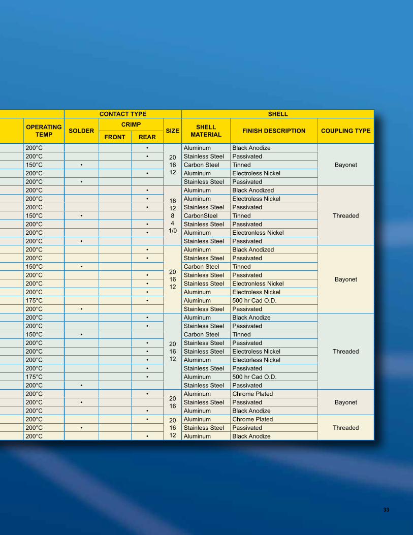
33
MILITARY SPECIFICATION
ENVIRONMENTAL AND MATERIAL
CLASS
PERFORMANCE CONTACT TYPE SHELL
DESCRIPTION FLUID RESISTANCE RESILIENT MATERIAL OPERATING
TEMP SOLDERCRIMP
SIZE SHELL MATERIAL FINISH DESCRIPTION COUPLING TYPE
FRONT REAR
MIL-DTL-83723 Series I
Section 9E
A Environmental Submersible Silicone 200°C •20 16 12
Aluminum Black Anodize
BayonetG Environmental Submersible Silicone 200°C • Stainless Steel PassivatedH Hermetic Splash-proof Silicone 150°C • Carbon Steel TinnedR Environmental Submersible Silicone 200°C • Aluminum Electroless NickelY Hermetic Submersible Silicone 200°C • Stainless Steel Passivated
MIL-DTL-83723 Series II
Section 1E
A Environmental Submersible Silicone 200°C •
16 12 8 4
1/0
Aluminum Black Anodized
Threaded
F Environmental, Superseded by Class R Submersible Silicone 200°C • Aluminum Electroless NickelG Environmental Submersible Silicone 200°C • Stainless Steel PassivatedH Hermetic Splash-proof Silicone 150°C • CarbonSteel TinnedK Environmental, Firewall Submersible Silicone 200°C • Stainless Steel PassivatedR Environmental Submersible Silicone 200°C • Aluminum Electronless NickelY Hermetic Submersible Silicone 200°C • Stainless Steel Passivated
MIL-DTL-83723 Series III Bayonet
Section 10D
A Environmental Submersible Silicone 200°C •
20 16 12
Aluminum Black Anodized
Bayonet
G Environmental Submersible Silicone 200°C • Stainless Steel PassivatedH Hermetic Splash-proof Silicone 150°C • Carbon Steel TinnedK Environmental, Firewall Submersible Silicone 200°C • Stainless Steel PassivatedN Environmental Submersible Silicone 200°C • Stainless Steel Electronless NickelR Environmental Submersible Silicone 200°C • Aluminum Electroless NickelW Environmental Submersible Silicone 175°C • Aluminum 500 hr Cad O.D.Y Hermetic Submersible Silicone 200°C • Stainless Steel Passivated
MIL-DTL-83723 Series III Threaded
Section 10D
A Environmental Submersible Silicone 200°C •
20 16 12
Aluminum Black Anodize
Threaded
G Environmental Submersible Silicone 200°C • Stainless Steel PassivatedH Hermetic Splash-proof Silicone 150°C • Carbon Steel TinnedK Environmental Firewall Submersible Silicone 200°C • Stainless Steel PassivatedN Environmental Submersible Silicone 200°C • Stainless Steel Electroless NickelR Environmental Submersible Silicone 200°C • Aluminum Electorless NickelS Environmental, EMI Self Locking Firewall Submersible Silicone 200°C • Stainless Steel PassivatedW Environmental Submersible Silicone 175°C • Aluminum 500 hr Cad O.D.Y Hermetic Submersible Silicone 200°C • Stainless Steel Passivated
NAS1599 Bayonet
Section 24
G Environmental Submersible Silicone 200°C •20 16
Aluminum Chrome PlatedBayonetH Hermetic Submersible Silicone 200°C • Stainless Steel Passivated
R Environmental Submersible Silicone 200°C • Aluminum Black AnodizeNAS1599 Threaded Section 24
G Environmental Submersible Silicone 200°C • 20 16 12
Aluminum Chrome PlatedThreadedH Hermetic Submersible Silicone 200°C • Stainless Steel Passivated
R Environmental Submersible Silicone 200°C • Aluminum Black Anodize
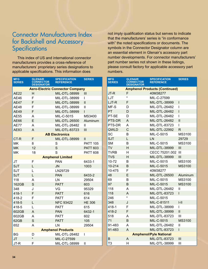
Connector Manufacturers Index for Backshell and Accessory Specifications
This index of US and international connector manufacturers provides a cross-reference of manufacturers’ proprietary series designations to applicable specifications. This information does
not imply qualification status but serves to indicate that the manufacturers’ series is “in conformance with” the noted specifications or documents. The symbols in the Connector Designator column are an essential element in Glenair’s accessory part number developments. For connector manufacturers’ part number series not shown in these listings, please consult factory for applicable accessory part numbers.
MFG SERIES
GLENAIR CONNECTOR DESIGNATOR
SPECIFICATION REFERENCE
SERIES
JT-R F 40M38277LJT * MIL-C-27599LJT-R F MIL-DTL-38999 IMF-S D MIL-DTL-26482 IPT D MIL-DTL-26482 IPT-SE D MIL-DTL-26482 IPTS-DR A MIL-DTL-26482 IIPTS-DR A MIL-DTL-83723 IQWLD C MIL-DTL-22992 RSC B MIL-C-5015 MS3100SJT L LN 29729SM B MIL-C-5015 MS3100TV H MIL-DTL-38999 IIITVRB H CECC 75201.002 IIITVS H MIL-DTL-38999 III10-72 B MIL-C-5015 MS310010-214 B MIL-C-5015 MS310010-475 F 40M3827748 E MIL-DTL-26500 Aluminum69 B MIL-C-5015 MS310097 B MIL-C-5015 MS3100118 A MIL-DTL-26482 II118 A MIL-DTL-83723 I246 * MIL-C-5015348 J MIL-C-81511 I-II418-1 F MIL-DTL-38999 I418-2 F MIL-DTL-38999 II518 A MIL-DTL-83723 III71 B MIL-C-5015 MS310091-483 A MIL-DTL-26482 II91-483 A MIL-DTL-83723 I
Amphenol/Pyle NationalB A MIL-DTL-83723 IIIT3 H MIL-DTL-38999 III
MFG SERIES
GLENAIR CONNECTOR DESIGNATOR
SPECIFICATION REFERENCE
SERIES
AE22 H MIL-DTL-38999 IIIAE46 F MIL-DTL-38999 IAE47 F MIL-DTL-38999 IIAE48 F MIL-DTL-38999 IIAE49 F MIL-DTL-38999 IAE55 A MIL-C-5015 MS3400AE66 E MIL-DTL-26500 AluminumAE77 A MIL-DTL-26482 IIAE83 A MIL-DTL-83723 III
AB ElectronicsCT-R F MIL-DTL-38999 IIMK 8 S PATT 105MK 12 S PATT 603MK 18 S PATT 608
Amphenol LimitedJT F PAN 6433-1SJT L JN 1003SJT L LN29729SJT L PAN 6433-2118 A LN 29504162GB S PATT 603348 J VG 95329418-1 F PATT 616418-2 F PATT 614418-5 L NFC 93422 HE 306418-5 L PATT 615602GB A PAN 6432-1602GB A PATT 60262GB S PATT 105652 A LN 29504
Amphenol ProductsBG D MIL-DTL-26482 IJT * MIL-C-27599JT-R F MIL-DTL-38999 II
Aero-Electric Connector Company Amphenol Products (Continued)
34

MFG SERIES
GLENAIR CONNECTOR DESIGNATOR
SPECIFICATION REFERENCE
SERIES
837 A MIL-DTL-83723 IIIDeutsch Limited
LL J MIL-C-81511 III-IVDBAS A PAN 6432-2DTS H MIL-DTL-38999 IIIHDJ L JN 1003RR A PAN 6432-1RR A PATT 602RR70 A QPL-81703 IIISLPT * MIL-DTL-26482 I
Glenair90 G MIL-DTL-2884080 M Mighty Mouse 800 Thru 80522 W Geo-Marine®
ITS, IT R MIL-C-5015231 F MIL-DTL-38999 1232 F MIL-DTL-38999 2233 H MIL-DTL-38999 3
SouriauBT D MIL-DTL-26482 IG D MIL-DTL-26482 IL D MIL-DTL-26482 IL-T D MIL-DTL-26482 IM-T D MIL-DTL-26482 IJVS H CECC 75201.0028LT F MIL-DTL-38999 I8LT F NFC 93422 HE 3088ST L JN 1003 8ST-0348ST L LN 297298ST L NFC 93422 HE 3068ST L PAN 6433-28ST L PATT 6158ST L VG 969128T F MIL-DTL-38999 II8T F NFC 93422 HE 30985 D MIL-DTL-26482 I851 S PATT 603851-50 * NFL53125851-50 * VG 953288525 A NFC 93422 HE 3028525.1 A LN 295048526 A MIL-DTL-26482 II8526 A PAN 6432-18526 A PATT 602
MFG SERIES
GLENAIR CONNECTOR DESIGNATOR
SPECIFICATION REFERENCE
SERIES
ZZW E MIL-DTL-26500 AluminumZZY E MIL-DTL-26500 Aluminum
A ESC 10, ESC 11Amphenol/Tuchel Electronics GmbH
118 A LN 29504162GB * VG 95328348 J VG 95329602GB A DEF 5326-3602GB A PAN 6432-1602GB A PATT 60262GB * DEF 5326-3652 A LN 29504
Cie Deutsch & Compagnie Deutsch GmbHAFD A LN 29504AFD A MIL-DTL-26482 IAFD A PAN 6432-1DBAS A QPL-81703 IIIDBAS A PAN 6432-2DFE A LN 29504DVG A VG 95328FDBA A LN 29504951 A PRL 531259.815 J MIL-C-81511 III & IV991 A PAN 6432-4999.1 F MIL-DTL-38999 I
A ESC 10A ESC 11
Deutsch Engineered Connecting DevicesAFD5 A MIL-DTL-26482 IIAFD A MIL-DTL-83723 IA815 J MIL-C-81511 IIIB815 J MIL-C-81511 IVBMS E MIL-C-26500BTK D MIL-DTL-26482 IDBA A 40M39569DBA7 A QPL-81703 IIIDTS H MIL-DTL-38999 IIIDIV4 H MIL-DTL-38999 IVDL6 A MIL-DTL-83723 IIID817 A QPL-81703 IIILPT D MIL-DTL-26482 I381 A 40M39569450 D MIL-DTL-26482 I460 D MIL-DTL-26482 I
Amphenol/Pyle National (Continued) Deutsch Engineered Connecting Devices (Continued)
35

MFG SERIES
GLENAIR CONNECTOR DESIGNATOR
SPECIFICATION REFERENCE
SERIES
8533 A EN 29928533 A ESC 108534 A ESC 11 8534
FC * MIL-C-5015FF A MIL-C-5015 MS3400FH * MIL-C-5015FHA K MIL-DTL-83723 IIPL H MIL-DTL-38999 IV
G & H TechnologiesBL H MIL-DTL-38999 IVNC G MIL-DTL-28840
ITT CannonCA3106B * VG95234CA-E / R B MIL-C-5015 MS3100CA-RX B MIL-C-5015 MS3100CVA K MIL-DTL-83723 IICV340 A MIL-C-5015 MS3400CV345 A MIL-C-5015 MS3450KFS G MIL-DTL-28840KJ F MIL-DTL-38999 IIKJ F 40M38277KJA H MIL-DTL-38999 IIIKJL F MIL-DTL-38999 IKPSE D MIL-DTL-26482 IKPT D MIL-DTL-26482 IMF A MIL-DTL-83723 IIIPV-G A 40M39569PVA A MIL-DTL-83723 IPV7 A MIL-DTL-26482 IIA ESC 10 KE, SE
ITT Cannon Electric France SAKJ F MIL-DTL-38999 IIKJ F PAN 6433-1KJL F MIL-DTL-38999 I251 * MIL-DTL-26482 I
ITT Cannon UK Ltd.KJ F PATT 614KPSE D MIL-DTL-26482 IPV-S A MIL-DTL-83723 IPVW A LN29504PVX A PAN 6432-1PVX A PATT 602A ESC 10 KE, SE
MFG SERIES
GLENAIR CONNECTOR DESIGNATOR
SPECIFICATION REFERENCE
SERIES
CA3106B * VG 95234CGK L LN 29729CWLD C MIL-DTL-22992 RKJ F PAN 6433-1KPSE * VG 95328KPT * VG 95328PVW A LN 29504PVX A PAN 6432-1
J-TechJT 3400 A MIL-C-5015 MS3400JT 3450 A MIL-C-5015 MS3450JTVG95234 A VG95234
Labinal/CinchCNO930 A MIL-DTL-83723 III48 E MIL-DTL-26500 Aluminum
RMSRO MIL-DTL-26500 Aluminum
Schaltbau GmbH650 J VG 95329674 * VG 95328675 * VG 95328679 J VG 95329
SICEMSCB * VG 95234
SunbankJSC MIL-DTL-28840
ITT CannonTT F PAN 6433-1PT S PATT 105PT-SE S PATT 603STT L LN 29729STT L PAN 6433-2STT L PATT 615STT L VG 96912
ITT VEAMCIR * VG 95234VPT D MIL-DTL-26482 IVPT-SE * MIL-DTL-26482 IVPT-SE * VG 95328
Flight Connector Corporation
ITT Cannon Electric GmbH
Connector Manufacturers Index for Backshell and Accessory Specifications (continued)
Souriau (continued)
36

First Numeral Second NumeralIP Protection of Persons Protection of Equipment IP Protection of Equipment
0 No Protection No Protection 0 No Protection
1Protected against contact with large areas of the body (back of hand)
Protected against objects over 50 mm in diameter 1
Protected against vertically falling drops of water, e.g. condensation
2 Protected against contact with fingers
Protected against solid objects over 12 mm in diameter
2 Protected against direct sprays of water up to 15° from vertical
3Protected against tools and wires over 2.5 mm in diameter
Protected against solid objects over 2.5 mm in diameter
3 Protected against sprays to 60° from vertical
4Protected against tools and wires over 1 mm in diameter
Protected against objects over 1 mm in diameter 4
Protected against water sprayed from all directions (limited ingress permitted)
5Protected against tools ad wires over 1 mm in diameter
Protected against dust (limited ingress, no harmful deposit
5Protected against low pressure jets of water from all directions (limited ingress permitted)
6Protected against tools and wires over 1 mm in diameter
Totally protected against dust 6 Protected against strong jets of water
7Protected against the effects of immersion between 15 cm and 1 m
8 Protected against long periods of immersion under pressure
Example RatingIf the 1st IP number is… and the 2nd IP number is… Then the IP rating is2 3 IP 2 3(protection against solid objects) (protection against liquids) (An enclosure with this designation provides protection against touch with a finger
and penetration of solid objects greater than 12 mm and against spraying water.)
International Standards IP Protection ClassificationIEC Publication 60529 Classification of Degrees of Protection by Enclosures provides a system for specifying
enclosures of electrical equipment on the basis of the degree of protection required. IEC 60529 does not specify degrees of protection against risk of explosions or conditions such as moisture (produced, for example, by condensation), corrosive vapors, fungus, or vermin. NEMA Standards Publication 250 does test for environmental conditions such as corrosion, rust, icing, oil, and coolants. For this reason, and because the tests and evaluations for other characteristics are not identical, the IEC enclosure classification designations cannot be exactly equated with NEMA enclosure Type numbers.
Levels of SealingConnector Type Seal Rating Sealing Method Typical Shell Material Contact MaterialDust Tight IP 65 Elastomer and/or epoxy Aluminum or Plastic BeCu/Brass/others
Environmental IP 66 Elastomer and/or epoxy Aluminum or Plastic BeCu/Brass/others
Environmental IP 67 Elastomer and/or epoxy Aluminum or Plastic BeCu/Brass/others
Environmental IP 68 Elastomer and/or epoxy Aluminum or Plastic BeCu/Brass/others
Semi-Hermetic (-491 Mod Code) 1 X 10 -4 Epoxy Special Aluminum Special
Hermetic 1 X 10 -4 Glass (soft) to Metal Aluminum BeCu/other
Hermetic 1 X 10 -6 Glass to Metal Cold Rolled Steel or Titanium Alloy 52 or Kovar
Hermetic 1 X 10 -8 Glass to Metal Stainless Steel or Kovar Alloy 52 or Kovar
Hermetic 1 X 10 -10 Glass to Metal Inconel or Stainless Steel Inconel or Stainless Steel
Kovar shell and contact are optimum for rectangular hermetic connectors Hermetic leak rate = CC He/Sec37

Save Time and Trouble with...
Mod 429 Space Grade ConnectorsVirtually any environmental connector package supplied by Glenair can be processed for DSCC approved space programs. NASA EEE-INST-002 provides guidance on additional screening for connectors. Glenair Mod 429 upgrades inspection and screening to NASA requirements without the need for a customer Statement of Work or Specification Control Drawing. This section of the Environmental Connector Reference Guide explains Glenair Mod 429 ordering, and provides valuable information on outgassing and other space flight topics.
This section will provide answers for the following frequently asked questions regarding:
Connectors used in space grade applications
1.Outgassing:What is outgassing, why is it important, and how does it affect connector selection? Is special processing required to meet outgassing requirements?
2.screening:What is NASA screening and what level of screening is required?
3.MagneticPerMeability:Are nonmagnetic connectors required?
4.cryOgenicexPOsure: Are Nano connectors suitable for -200° C. exposure?
5.Materials:Nano connectors offer a variety of materials and plating finishes. Which ones are recommended for space flight?
6.WirecOrrOsiOn:M22759/33 irradiated Tefzel® wire is preferred for space applications. What about corrosion problems caused by this wire?
Mod 429 Space Grade Processing Information
38

NASA Screening Level
Special Screening Only
Special Screening Plus Outgassing Processing
8 Hour Oven Bake400° F.
Thermal Vacuum Outgassing
24 hrs. 125° C.
Level 1 Highest Reliability Mod 429B Mod 429J Mod 429C
Level 2 High Reliability Mod 429 Mod 429K Mod 429A
Level 3 Standard Reliability
(Use standard part number) Mod 186 Mod 186M
Quick Reference Guide: Specifying Space Grade Connectors
Select suitable shell materials and platingTitanium shells, nickel-plated aluminum shells and stainless steel shells are suitable for use in vacuum environments. Cadmium plating is prohibited for space flight.
Select a NASA Screening LevelThe term “Screening Level” refers to the final inspection procedure. Level 1 for mission-critical highest reliability Level 2 for high reliabilityLevel 3 for standard reliability
Outgassing ProcessingMost Glenair connectors are certified to meet NASA outgassing requirements without special processing. However, if additional outgassing processing is required, choose the appropriate suffix code from the table below.
Select the Mod 429 Code that Matches the DesiredLevel of Screening and OutgassingUse the following table to choose the right modification code. Add the mod code to the connector part number. Example: 233-105-07-M11-21SN-429
steP
1
steP
2
steP
3
steP
4
39

1.Outgassing:What is outgassing and how does it affect connector selection? Is special processing required to meet outgassing requirements?What is Outgassing?
Plastic and rubber materials give off gaseous molecules. For example, the smell inside a new car is caused by polymer outgassing. Heat and vacuum increase the rate of diffusion. In a spacecraft the gases coming off polymers can contaminate optical surfaces and instruments. The result is degraded performance.
How is Outgassing Measured?The space industry has adopted a
standardized test procedure, ASTM E 595, to evaluate out-gassing properties of polymers. Small samples of material are heated to 125° C. at a vacuum of 5 X 10⁻⁵ torr for 24 hours. Then the sample is weighed to calculate the Total Mass Loss (TML). The TML cannot exceed 1.00% of the total initial mass. During the test, outgassed matter condenses on a cooled collector plate. The quantity of outgassed matter is calculated to determine the Collected Volatile Condensable Material (CVCM). The CVCM cannot exceed 0.10% of the original specimen mass.
Do All Connectors Require Special Outgassing Processing?
No. Most connectors meet NASA outgassing requirements without special processing.
2.screening:What is NASA screening and what level of screening is required? What is NASA Screening?
NASA specification EEE-INST-002 provides instructions on selecting, screening and qualifying parts for use on NASA GSFC space flight projects. Table 2J in the NASA spec contains specific
inspection instructions for Nanominiature connectors. These screening requirements exceed the standard mil spec inspection levels.
What Screening Level is Required for Space Applications?
NASA defines three levels of screening: level 1 for highest reliability, level 2 for high reliability, and level 3 for standard reliability.
Is Glenair NASA Certified?Yes. Meeting NASA requirements means
not only inspecting per EEE-INST-002, but also building parts in accordance with NASA Technical Standard NASA-STD-8739.4 “Crimping, Interconnecting Cables, Harnesses, and Wiring”. Glenair fully meets these requirements and has obtained NASA certification. Our extra inspection steps reflect the fact that pre-wired connectors not only require best practices on the assembly floor, but also require thorough final electrical and mechanical testing.
SCREENING REQUIREMENTS
Inspection/ TestGlenair Level 1
(Mod 429B)Glenair Level 2
(Mod 429)
Visual Inspection 100% (10X) 100%
Mechanical 100% 2 pcs.
Voltage (DWV) 100% 100%
Insulation Resistance 100% 100%
Low Level Contact Resistance 100% (Read and Record) 2 pcs. (Read and Record)
Mating Force 2 pcs. N/A
Contact/Wire Retention 2 pcs. N/A
Solderability/Resistance to Soldering Heat 2 pcs. N/A
Mod 429 Space Grade Processing Information
40

6.WirecOrrOsiOn:M22759/33 irradiated Tefzel® wire is preferred for space applications. What about corrosion problems caused by this wire?Does M22759/33 Wire Have an Outgassing Problem?
Irradiated Tefzel® wire is known to cause tarnishing and corrosion of metal parts in close proximity, usually in sealed bags. Both MIL-DTL-32139 and NASA EEE-INST-002 contain cautionary notes regarding this problem. Wire manufacturers have not been able to eliminate this problem. This corrosion problem is referred to as “wire outgassing”, which has led to confusion over the term outgassing. This problem has nothing to do with the ability of the wire to meet the TML and CVCM outgassing requirements of ASTM E595. M22759/33 irradiated Tefzel wire continues to be the wire of choice for spacecraft. This wire complies with outgassing requirements.
Connectors with M22759/33 wire should not be stored in sealed bags for extended periods.
New Unit Pack Minimizes CorrosionGlenair has adopted an inovative new
packaging system to protect connectors from performance hindering corrosion. Metal shell connectors supplied wtih M22759/33 wire are now packaged as follows: the connector is wrapped in Teflon® tape and placed in a ventilated sulpher-free paper envelope to ensure that your mission-critical component arrives in perfect order.
3.MagneticPerMeability:Are nonmagnetic connectors required?
Spacecraft designers generally avoid the use of ferromagnetic materials, which can become magnetized and can interfere with sensitive instruments. Nano connectors have a maximum permeability of 2 mu.
4.cryOgenicexPOsure:Are Glenair connectors suitable for use at temperatures approaching -200° C. ?
Most Glenair environmental connectors are rated to -55° C. Glenair has not performed testing below this temperature. EEE-INST-002 states “...experience has proven it is possible for (non-certified) connector types to be used successfully at cryogenic temperatures. It is recommended that connector samples should be subjected to five cycles of cryogenic temperature...(followed by examination for cracks and DWV)”.
5.Materials:Which materials are recommended for space flight?
Cadmium plated shells are prohibited from space programs. Other plating materials are acceptable.
OUTGASSING PROPERTIES OF NANO CONNECTORS
Component Material Brand Name % Total Mass Loss
% Collected Volatile Condensable Material Test Report
Thermoplastic Insulators and PCB Trays
Liquid Crystal Polymer Vectra® C-130 0.03 0.00 NASA Test
#GSC17478
Potting Compound Epoxy Hysol C9-4215 0.48 0.01 Glenair Test
Wire Tefzel® Tefzel® 0.22 0.01 NASA Test #GSC19998
41

Nonmetallic materials such as rubber, plastic, adhesives and potting compounds can give off gasses when subjected to a vacuum or high heat. The space industry has adopted a standardized test procedure, ASTM E 595, to evaluate outgassing properties of products that contain polymer materials. In the ASTM test, material samples are heated to 125° C at a vacuum of 5 X 10⁻⁵ torr for 24 hours. The test sample is then weighed to calculate the Total Mass Loss (TML), which may not exceed 1.00% of the total initial mass. Likewise the quantity of outgassed matter is weighed to determine the Collected Volatile Condensable Material (CVCM), which may not exceed 0.10% of the original specimen mass.
For space grade applications, Glenair is able to offer both an 8 hour 400° bakeout process as well as a 24 hour 125° thermal vacuum outgassing process on connector products that must conform
to NASA screening or other outgassing standards. Our experience has been that the simpler bakeout process is more than adequate to meet the ASTM E 595 benchmark of 1.00% TML and 0.10% CVCM.
Glenair is well versed in supplying connector products that are optimized for use in space grade applications, and we supply MIL DTL-38999 type compliant to EEE-INST-002, Table 2G, the recognized standard for space grade connectors. Section C2 “Connectors and Contacts” of NASA EEE-INST-002 provides guidelines for materials used in connectors for space .ight applications: Aluminum is a preferred material for connector components, and electroless nickel is the preferred finish. Beryllium copper is a preferred material for contacts. 50 microinch minimum gold plating is the preferred contact finish. LCP is a preferred material for dielectric insulating materials. Specify “M” for aluminum shells with electroless nickel finish.
Outgassing Properties and Processing
OUTGASSING PROPERTIES OF MATERIALS USED IN MIL-DTL-38999 CONNECTORSComponent Material TML % TCVML
%Test Reference
Front and Rear Insulator Liquid Crystal Polymer Vectra C130 0.03 0.0 NASA Test # GSC17478Rear Grommet Interfacial Seal Peripheral Seal
Blended fluorosilicone/silicone elastomer, 30% silicone per ZZ-R-765, 70% flourosilicone per MIL-R-25988
0.48 0.14 Glenair testing conducted at NuSil Technology 02/27/2001
Front-To-Rear Insulator Bonding Material
Eccobond 104 A/B 0.52 0.08 Emerson & Cuming Data Sheet
Insulator-to-Rubber Bonding Material
DC3145 RTV, per MIL-A-46146 1.74 0.90 NASA Test GSFC0191
Coupling Nut Retainer Torlon® 4203L 1.88 0.01 Glenair Test at NuSil Technology 03-12-2003
Coupling Nut Epoxy Hysol C9-4215 0.48 0.01 Glenair TestWhite Epoxy Ink for Silk-screening
Markem 7224 White 0.49 0.03 NASA Test #GSC19899
Potting Compound, Solder Cup and PC Tail Connectors
Hysol C9-4215 0.48 0.01 Glenair Test
Potting Compound, Filter Receptacles
Stycast epoxy, 2850FT/Catalyst 11 0.29 0.02 Mfgr Data Sheet
Mod 429 Space Grade Processing Information
42
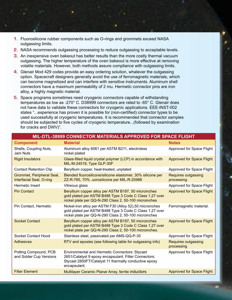
1. Fluorosilicone rubber components such as O-rings and grommets exceed NASA outgassing limits.
2. NASA recommends outgassing processing to reduce outgassing to acceptable levels. 3. An inexpensive oven bakeout has better results than the more costly thermal vacuum
outgassing. The higher temperature of the oven bakeout is more effective at removing volatile materials. However, both methods assure compliance with outgassing limits.
4.Glenair Mod 429 codes provide an easy ordering solution, whatever the outgassing option. Spacecraft designers generally avoid the use of ferromagnetic materials, which can become magnetized and can interfere with sensitive instruments. Aluminum shell connectors have a maximum permeability of 2 mu. Hermetic connector pins are iron alloy, a highly magnetic material.
5. Space programs sometimes need cryogenic connectors capable of withstanding temperatures as low as -270° C. D38999 connectors are rated to -65° C. Glenair does not have data to validate these connectors for cryogenic applications. EEE-INST-002 states “...experience has proven it is possible for (non-certified) connector types to be used successfully at cryogenic temperatures. It is recommended that connector samples should be subjected to five cycles of cryogenic temperature...(followed by examination for cracks and DWV)”.
MIL-DTL-38999 CONNECTOR MATERIALS APPROVED FOR SPACE FLIGHTComponent Material Notes Shells, Coupling Nuts, Jam Nuts
Aluminum alloy 6061 per ASTM B211, electroless nickel plated
Approved for Space Flight
Rigid Insulators Glass-filled liquid crystal polymer (LCP) in accordance with MIL-M-24519, Type GLP-30F
Approved for Space Flight
Contact Retention Clip Beryllium copper, heat-treated, unplated Approved for Space FlightGrommet, Peripheral Seal, Interfacial Seal, O-ring
Blended fluorosilicone/silicone elastomer, 30% silicone per ZZ-R-765, 70% .uorosilicone per MIL-R-25988
Requires outgassing processing
Hermetic Insert Vitreous glass Approved for Space FlightPin Contact Beryllium copper alloy per ASTM B197, 50 microinches
gold plated per ASTM B488 Type 3 Code C Class 1,27 over nickel plate per QQ-N-290 Class 2, 50-100 microinches
Approved for Space Flight
Pin Contact, Hermetic Nickel-iron alloy per ASTM F30 (Alloy 52),50 microinches gold plated per ASTM B488 Type 3 Code C Class 1,27 over nickel plate per QQ-N-290 Class 2, 50-100 microinches
Ferromagnetic material.
Socket Contact Beryllium copper alloy per ASTM B197, 50 microinches gold plated per ASTM B488 Type 3 Code C Class 1,27 over nickel plate per QQ-N-290 Class 2, 50-100 microinches.
Approved for Space Flight
Socket Contact Hood Stainless steel, passivated per AMS-QQ-P-35 Approved for Space FlightAdhesives RTV and epoxies (see following table for outgassing info) Requires outgassing
processingPotting Compound, PCB and Solder Cup Versions
Environmental and Hermetic Connectors: Stycast 2651/Catalyst 9 epoxy encapsulant. Filter Connectors: Stycast 2850FT/Catalyst 11 thermally conductive epoxy encapsulant.
Approved for Space Flight
Filter Element Multilayer Ceramic Planar Array, ferrite inductors Approved for Space Flight
43

44
Code Material Finish Finish SpecificationHrs. Salt Spray
Electrical Conductivity
Operating Temp. Range Notes
A Aluminum Cadmium, No Chromate SAE-AMS-QQ-P-416 Type I Class 3 48 Conductive -65 to +175°C Not recommended for new projects. LF is preferred.AB Marine Bronze Unplated 1000 Conductive -65 to +200°C Marine and geophysical applications.AL Aluminum AlumiPlate, Clear Chromate MIL-DTL-83488, Class 2, Type II over electroless nickel 1000 Conductive -65 to +175°C Approved for MIL-DTL-38999L and MIL-DTL-83513G.B Aluminum Cadmium, Olive Drab SAE-AMS-QQ-P-416 Type II Class 3 96 Conductive -65 to +175°C Not recommended for new projects. NF is preferred.C Aluminum Anodize, Black AMS-A-8625 Type II Class 2 336 Non-Conductive -65 to +175°C Glenair’s standard black anodize finish.E Aluminum Chem Film MIL-DTL-5541 Type 1 Class 3 168 Conductive -65 to +175°C Glenair’s standard chem film finish.G Aluminum Anodize, Hardcoat AMS-A-8625 Type III, Class 1, .001" thick 336 Non-Conductive -65 to +200°C Not recommended for new projects. G2 is preferred.
G2 Aluminum Anodize, Hardcoat AMS-A-8625, Type III, Class 1, .002" thick 336 Non-Conductive -65 to +200°C Dark olive grey color. Glenair’s preferred hardcoat finish.J Aluminum Cadmium, Gold SAE-AMS-QQ-P-416 Type II, Class 2 over electroless nickel 500 Conductive -65 to +175°C Not recommended for new projects. JF is preferred.
JF Aluminum Cadmium, Gold SAE-AMS-QQ-P-416 Type II, Class 2 over electroless nickel 1000 Conductive -65 to +175°C Glenair’s preferred gold cadmium finish.LF Aluminum Cadmium, Clear SAE-AMS-QQ-P-416 Type II Class 2 over electroless nickel 1000 Conductive -65 to +175°C Glenair’s preferred clear cadmium finish.M Aluminum Electroless Nickel AMS-C-26074 Class 4 Grade B; ASTM-B-733, SC 2, Type IV 48 Conductive -65 to +200°C Glenair’s standard electroless nickel finish.
MT Aluminum Nickel-PTFE GMF-002 Type II Class 1 1000 Conductive -65 to +175°C Approved for MIL-DTL-38999L and MIL-DTL-83513G.N Aluminum Cadmium, Olive Drab SAE-AMS-QQ-P-416 Type II Class 3 over electroless nickel 500 Conductive -65 to +175°C Not recommended for new projects. NF is preferred.
NC Aluminum Zinc-Cobalt, Olive Drab ASTM B 840 Grade 6 Type D over electroless nickel 350 Conductive -65 to +175°C Glenair’s standard olive drab zinc-cobalt finish.NF Aluminum Cadmium, Olive Drab SAE-AMS-QQ-P-416 Type II Class 2 over electroless nickel 1000 Conductive -65 to +175°C Glenair’s standard olive drab cadmium finish.P Stainless Steel Electrodeposited Nickel SAE-AMS-QQ-N-290 Class 1 Grade F 500 Conductive -65 to +200°C Not recommended for new projects. ZM is preferred.T Aluminum Cadmium, No Chromate SAE-AMS-QQ-P-416 Type I Class 3 48 Conductive -65 to +175°C Not recommended for new projects. LF is preferred.
TP2 Titanium Electrodeposited Nickel SAE-AMS-QQ-N-290 Class 1 Grade F 96 Conductive -65 to +200°C Glenair’s preferred finish for titanium connectors.U Aluminum Cadmium, Black SAE-AMS-QQ-P-416 Type I Class 3 48 Conductive -65 to +175°C Not recommended for new projects. UF is preferred.
UC Aluminum Zinc-Cobalt, Black ASTM B 840 Grade 6 Type D over electroless nickel 350 Conductive -65 to +175°C Glenair’s standard black zinc-cobalt finish.UCR Aluminum Zinc-Cobalt, Black ASTM B 840 Grade 6 Type D over electroless nickel 350 Conductive -65 to +175°C RoHS version of UC.UF Aluminum Cadmium, Black SAE-AMS-QQ-P-416 Type II Class 2over electroless nickel 1000 Conductive -65 to +175°C Glenair’s preferred black cadmium finish.
XAL Composite AlumiPlate MIL-DTL-86448, Class 2, Type II over electroless nickel 2000 Conductive -65 to +175°C Approved for MIL-DTL-38999L.XB Composite Unplated Black 2000 Non-Conductive -65 to +175°C Glenair’s standard unplated composite.XM Composite Electroless Nickel AMS-C-26074 2000 Conductive -65 to +175°C Glenair’s standard electroless nickel finish over composite.
XMT Composite Nickel-PTFE GMS-002 Class 2 Type II 2000 Conductive -65 to +175°C Approved for MIL-DTL-38999L.XO Composite Unplated Light Brown 2000 Non-Conductive -65 to +175°C Not recommended for new projects. Use XB.XW Composite Cadmium, Olive Drab SAE-AMS-QQ-P-416 Type II Class 3 over electroless nickel 2000 Conductive -65 to +175°C Glenair’s standard olive drab cadmium finish over composite.XZN Composite Zinc-Nickel, Black ASTM B841 Grade 5 over electroless nickel 2000 Conductive -65 to +175°C Glenair’s standard black zinc-nickel finish over composite.Z1 Stainless Steel Passivate SAE-AMS-SAE-AMS-QQ-P-35 Type VI 1000 Conductive -65 to +200°C Glenair’s standard passivated stainless steel.Z2 Aluminum Gold MIL-DTL-45204 Class 1 over electroless nickel 48 Conductive -65 to +200°C Glenair’s standard gold plating for space programs.ZC Stainless Steel Zinc-Cobalt, Black ASTM-B840, Grade 6 Conductive -65 to +175°C Glenair’s standard zinc-cobalt over stainless steel.
ZCR Stainless Steel Zinc-Cobalt, Black ASTM-B840, Grade 6 Conductive -65 to +175°C RoHS version of ZC.ZL Stainless Steel Electrodeposited Nickel SAE-AMS-QQ-N-290 Class 1 Grade F 1000 Conductive -65 to +200°C Used on hermetic connectors. Use ZM for other applications.ZM Stainless Steel Electroless Nickel AMS-C-26074 Class 1 Grade A Conductive -65 to +200°C Glenair’s preferred nickel-plated stainless steel.
ZMT Stainless Steel Nickel-PTFE GMF-002 Type II Class 3 1000 Conductive -65 to +175°C Glenair’s new 1000 Hour Grey over stainless steel.ZN Aluminum Zinc-Nickel, Olive Drab ASTM B841 Grade 5 over electroless nickel 1000 Conductive -65 to +175°C Glenair’s standard olive drab zinc-nickel finish.
ZNU Aluminum Zinc-Nickel, Black ASTM B841 Grade 5 over electroless nickel 1000 Conductive -65 to +175°C Glenair’s standard black zinc-nickel finish.ZU Stainless Steel Cadmium, Black SAE-AMS-QQ-P-416 Type II Class 3 1000 Conductive -65 to +175°C Glenair’s standard black cadmium over stainless steel.ZW Stainless Steel Cadmium, Olive Drab SAE-AMS-QQ-P-416 Type II Class 2 over electroless nickel 2000 Conductive -65 to +175°C Glenair’s standard olive drab cadmium over stainless steel.
Glenair Material and Finish Options

45
Code Material Finish Finish SpecificationHrs. Salt Spray
Electrical Conductivity
Operating Temp. Range Notes
A Aluminum Cadmium, No Chromate SAE-AMS-QQ-P-416 Type I Class 3 48 Conductive -65 to +175°C Not recommended for new projects. LF is preferred.AB Marine Bronze Unplated 1000 Conductive -65 to +200°C Marine and geophysical applications.AL Aluminum AlumiPlate, Clear Chromate MIL-DTL-83488, Class 2, Type II over electroless nickel 1000 Conductive -65 to +175°C Approved for MIL-DTL-38999L and MIL-DTL-83513G.B Aluminum Cadmium, Olive Drab SAE-AMS-QQ-P-416 Type II Class 3 96 Conductive -65 to +175°C Not recommended for new projects. NF is preferred.C Aluminum Anodize, Black AMS-A-8625 Type II Class 2 336 Non-Conductive -65 to +175°C Glenair’s standard black anodize finish.E Aluminum Chem Film MIL-DTL-5541 Type 1 Class 3 168 Conductive -65 to +175°C Glenair’s standard chem film finish.G Aluminum Anodize, Hardcoat AMS-A-8625 Type III, Class 1, .001" thick 336 Non-Conductive -65 to +200°C Not recommended for new projects. G2 is preferred.
G2 Aluminum Anodize, Hardcoat AMS-A-8625, Type III, Class 1, .002" thick 336 Non-Conductive -65 to +200°C Dark olive grey color. Glenair’s preferred hardcoat finish.J Aluminum Cadmium, Gold SAE-AMS-QQ-P-416 Type II, Class 2 over electroless nickel 500 Conductive -65 to +175°C Not recommended for new projects. JF is preferred.
JF Aluminum Cadmium, Gold SAE-AMS-QQ-P-416 Type II, Class 2 over electroless nickel 1000 Conductive -65 to +175°C Glenair’s preferred gold cadmium finish.LF Aluminum Cadmium, Clear SAE-AMS-QQ-P-416 Type II Class 2 over electroless nickel 1000 Conductive -65 to +175°C Glenair’s preferred clear cadmium finish.M Aluminum Electroless Nickel AMS-C-26074 Class 4 Grade B; ASTM-B-733, SC 2, Type IV 48 Conductive -65 to +200°C Glenair’s standard electroless nickel finish.
MT Aluminum Nickel-PTFE GMF-002 Type II Class 1 1000 Conductive -65 to +175°C Approved for MIL-DTL-38999L and MIL-DTL-83513G.N Aluminum Cadmium, Olive Drab SAE-AMS-QQ-P-416 Type II Class 3 over electroless nickel 500 Conductive -65 to +175°C Not recommended for new projects. NF is preferred.
NC Aluminum Zinc-Cobalt, Olive Drab ASTM B 840 Grade 6 Type D over electroless nickel 350 Conductive -65 to +175°C Glenair’s standard olive drab zinc-cobalt finish.NF Aluminum Cadmium, Olive Drab SAE-AMS-QQ-P-416 Type II Class 2 over electroless nickel 1000 Conductive -65 to +175°C Glenair’s standard olive drab cadmium finish.P Stainless Steel Electrodeposited Nickel SAE-AMS-QQ-N-290 Class 1 Grade F 500 Conductive -65 to +200°C Not recommended for new projects. ZM is preferred.T Aluminum Cadmium, No Chromate SAE-AMS-QQ-P-416 Type I Class 3 48 Conductive -65 to +175°C Not recommended for new projects. LF is preferred.
TP2 Titanium Electrodeposited Nickel SAE-AMS-QQ-N-290 Class 1 Grade F 96 Conductive -65 to +200°C Glenair’s preferred finish for titanium connectors.U Aluminum Cadmium, Black SAE-AMS-QQ-P-416 Type I Class 3 48 Conductive -65 to +175°C Not recommended for new projects. UF is preferred.
UC Aluminum Zinc-Cobalt, Black ASTM B 840 Grade 6 Type D over electroless nickel 350 Conductive -65 to +175°C Glenair’s standard black zinc-cobalt finish.UCR Aluminum Zinc-Cobalt, Black ASTM B 840 Grade 6 Type D over electroless nickel 350 Conductive -65 to +175°C RoHS version of UC.UF Aluminum Cadmium, Black SAE-AMS-QQ-P-416 Type II Class 2over electroless nickel 1000 Conductive -65 to +175°C Glenair’s preferred black cadmium finish.
XAL Composite AlumiPlate MIL-DTL-86448, Class 2, Type II over electroless nickel 2000 Conductive -65 to +175°C Approved for MIL-DTL-38999L.XB Composite Unplated Black 2000 Non-Conductive -65 to +175°C Glenair’s standard unplated composite.XM Composite Electroless Nickel AMS-C-26074 2000 Conductive -65 to +175°C Glenair’s standard electroless nickel finish over composite.
XMT Composite Nickel-PTFE GMS-002 Class 2 Type II 2000 Conductive -65 to +175°C Approved for MIL-DTL-38999L.XO Composite Unplated Light Brown 2000 Non-Conductive -65 to +175°C Not recommended for new projects. Use XB.XW Composite Cadmium, Olive Drab SAE-AMS-QQ-P-416 Type II Class 3 over electroless nickel 2000 Conductive -65 to +175°C Glenair’s standard olive drab cadmium finish over composite.XZN Composite Zinc-Nickel, Black ASTM B841 Grade 5 over electroless nickel 2000 Conductive -65 to +175°C Glenair’s standard black zinc-nickel finish over composite.Z1 Stainless Steel Passivate SAE-AMS-SAE-AMS-QQ-P-35 Type VI 1000 Conductive -65 to +200°C Glenair’s standard passivated stainless steel.Z2 Aluminum Gold MIL-DTL-45204 Class 1 over electroless nickel 48 Conductive -65 to +200°C Glenair’s standard gold plating for space programs.ZC Stainless Steel Zinc-Cobalt, Black ASTM-B840, Grade 6 Conductive -65 to +175°C Glenair’s standard zinc-cobalt over stainless steel.
ZCR Stainless Steel Zinc-Cobalt, Black ASTM-B840, Grade 6 Conductive -65 to +175°C RoHS version of ZC.ZL Stainless Steel Electrodeposited Nickel SAE-AMS-QQ-N-290 Class 1 Grade F 1000 Conductive -65 to +200°C Used on hermetic connectors. Use ZM for other applications.ZM Stainless Steel Electroless Nickel AMS-C-26074 Class 1 Grade A Conductive -65 to +200°C Glenair’s preferred nickel-plated stainless steel.
ZMT Stainless Steel Nickel-PTFE GMF-002 Type II Class 3 1000 Conductive -65 to +175°C Glenair’s new 1000 Hour Grey over stainless steel.ZN Aluminum Zinc-Nickel, Olive Drab ASTM B841 Grade 5 over electroless nickel 1000 Conductive -65 to +175°C Glenair’s standard olive drab zinc-nickel finish.
ZNU Aluminum Zinc-Nickel, Black ASTM B841 Grade 5 over electroless nickel 1000 Conductive -65 to +175°C Glenair’s standard black zinc-nickel finish.ZU Stainless Steel Cadmium, Black SAE-AMS-QQ-P-416 Type II Class 3 1000 Conductive -65 to +175°C Glenair’s standard black cadmium over stainless steel.ZW Stainless Steel Cadmium, Olive Drab SAE-AMS-QQ-P-416 Type II Class 2 over electroless nickel 2000 Conductive -65 to +175°C Glenair’s standard olive drab cadmium over stainless steel.
This chart presents a selection of the broad range of base materials and plating options available from Glenair. Innovation and qualification of material and finish types is a major Glenair strength.
RoHS

46
MIL-DTL-38999 Series III and IV Class Code Material, Finish
Recommended Glenair
Accessory Code
C Aluminum, Anodize, Hardcoat G2F Aluminum, Electroless Nickel MG Aluminum, Electroless Nickel MH Stainless Steel, Passivated Z1J Composite, Cadmium Plated, Olive Drab XWK Stainless Steel, Passivated Z1L Stainless Steel, Electrodeposited Nickel PM Composite, Electroless Nickel Plated XMP Aluminum, Pure Dense Aluminum (AlumiPlateSM) ALR Aluminum, Electroless Nickel MS Stainless Steel, Electrodeposited Nickel PT Aluminum, Nickel-PTFE MTW Aluminum, Cadmium Plated, Olive Drab NFX Aluminum, Cadmium Plated, Olive Drab NFZ Aluminum, Black Zinc-Nickel ZR
MIL-DTL-38999 Series I and II Finish Code Material, Finish
Recommended Glenair
Accessory Code
A Aluminum, Cadmium Plated, Clear Chromate LFB Aluminum, Cadmium Plated, Olive Drab NFC Aluminum, Anodize, Hardcoat G2E Stainless Steel, Passivated Z1F Aluminum, Electroless Nickel Plated MN Stainless Steel, Electrodeposited Nickel (Hermetic) PP Aluminum, Pure Dense Aluminum (AlumiPlateSM) ALR Aluminum, Electroless Nickel MT Aluminum, Nickel-PTFE MTU Aluminum, Cadmium Plated, Clear Chromate LFX Aluminum, Cadmium Plated, Olive Drab NFZ Aluminum, Black Zinc-Nickel ZR
Glenair Backshell Plating Code and Mil-Spec Connector Finish Code Cross-Reference
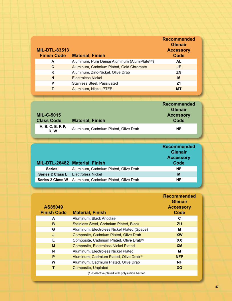
47
MIL-DTL-26482 Material, Finish
Recommended Glenair
Accessory Code
Series I Aluminum, Cadmium Plated, Olive Drab NFSeries 2 Class L Electroless Nickel MSeries 2 Class W Aluminum, Cadmium Plated, Olive Drab NF
MIL-C-5015 Class Code Material, Finish
Recommended Glenair
Accessory Code
A, B, C, E, F, P, R, W Aluminum, Cadmium Plated, Olive Drab NF
MIL-DTL-83513 Finish Code Material, Finish
Recommended Glenair
Accessory Code
A Aluminum, Pure Dense Aluminum (AlumiPlateSM) ALC Aluminum, Cadmium Plated, Gold Chromate JFK Aluminum, Zinc-Nickel, Olive Drab ZNN Electroless Nickel MP Stainless Steel, Passivated Z1T Aluminum, Nickel-PTFE MT
AS85049 Finish Code Material, Finish
Recommended Glenair
Accessory Code
A Aluminum, Black Anodize CB Stainless Steel, Cadmium Plated, Black ZUG Aluminum, Electroless Nickel Plated (Space) MJ Composite, Cadmium Plated, Olive Drab XWL Composite, Cadmium Plated, Olive Drab(1) XXM Composite, Electroless Nickel Plated XMN Aluminum, Electroless Nickel Plated MP Aluminum, Cadmium Plated, Olive Drab(1) NFPW Aluminum, Cadmium Plated, Olive Drab NFT Composite, Unplated XO
(1) Selective plated with polysulfide barrier
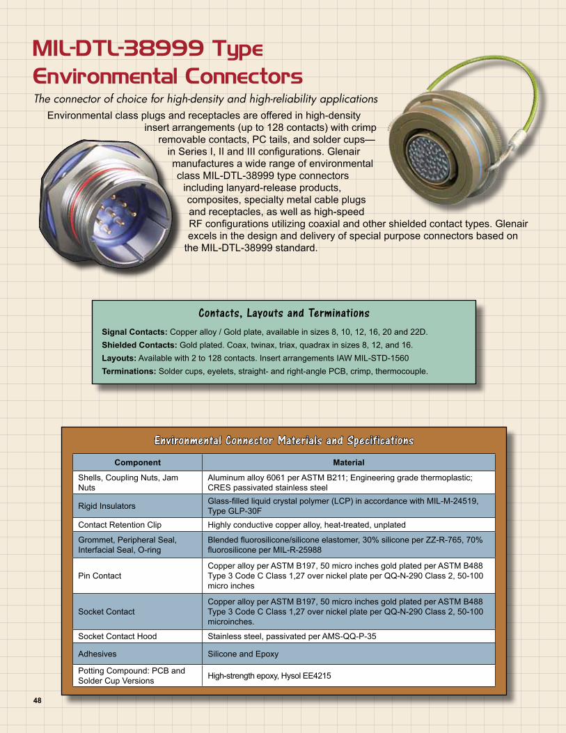
MIL-DTL-38999 Type Environmental Connectors The connector of choice for high-density and high-reliability applications
Environmental class plugs and receptacles are offered in high-density insert arrangements (up to 128 contacts) with crimp
removable contacts, PC tails, and solder cups—in Series I, II and III configurations. Glenair manufactures a wide range of environmental class MIL-DTL-38999 type connectors
including lanyard-release products, composites, specialty metal cable plugs and receptacles, as well as high-speed RF configurations utilizing coaxial and other shielded contact types. Glenair excels in the design and delivery of special purpose connectors based on
the MIL-DTL-38999 standard.
Environmental Connector Materials and Specifications
Component Material
Shells, Coupling Nuts, Jam Nuts
Aluminum alloy 6061 per ASTM B211; Engineering grade thermoplastic; CRES passivated stainless steel
Rigid Insulators Glass-filled liquid crystal polymer (LCP) in accordance with MIL-M-24519, Type GLP-30F
Contact Retention Clip Highly conductive copper alloy, heat-treated, unplated
Grommet, Peripheral Seal, Interfacial Seal, O-ring
Blended fluorosilicone/silicone elastomer, 30% silicone per ZZ-R-765, 70% fluorosilicone per MIL-R-25988
Pin ContactCopper alloy per ASTM B197, 50 micro inches gold plated per ASTM B488 Type 3 Code C Class 1,27 over nickel plate per QQ-N-290 Class 2, 50-100 micro inches
Socket ContactCopper alloy per ASTM B197, 50 micro inches gold plated per ASTM B488 Type 3 Code C Class 1,27 over nickel plate per QQ-N-290 Class 2, 50-100 microinches.
Socket Contact Hood Stainless steel, passivated per AMS-QQ-P-35
Adhesives Silicone and Epoxy
Potting Compound: PCB and Solder Cup Versions High-strength epoxy, Hysol EE4215
Contacts, Layouts and TerminationsSignal Contacts: Copper alloy / Gold plate, available in sizes 8, 10, 12, 16, 20 and 22D.Shielded Contacts: Gold plated. Coax, twinax, triax, quadrax in sizes 8, 12, and 16.Layouts: Available with 2 to 128 contacts. Insert arrangements IAW MIL-STD-1560Terminations: Solder cups, eyelets, straight- and right-angle PCB, crimp, thermocouple.
48

Service Rating Sea Level 70,000 ft..M 1300 VRMS 350 VRMSN 1000 VRMS 260 VRMSI 1800 VRMS 400 VRMSII 2300 VRMS 500 VRMS
Service RatingTest voltage, Volts AC (rms). Wired, assembled, unmated connectors:
Performance RatingsShock and Vibration 300 G’s Shock; 37 G’s Random Vibration
Thermal Shock -65° C to +175° C per EIA-364-32 test
Operating Temperature -55° C to +200° C
Mating Cycles 500 Mating Cycles
Corrosion Resistance 1000 Hours on Stainless Steel Shells
Shielding EffectivenessEffective over a range of 100MHz to 10GHz with a minimum 50dB effectiveness at 10GHz, IAW test method EIA-364-10
Shell-to-Shell Resistance 2 Millivolt drop maximum, per EIA-364-83
Contact Size Wire Gauge22D #22 - #2820 #20 - #2416 #16 - #2012 #12 - #1410 #10 - #12
Supported Wire Sizes
Mounting Style Part NumberWall Mount 233-105-00, D0 & T0
Jam Nut 233-105-07
In-Line Receptacle 233-105-05
Plug Connector 233-105-G6
Box Mount with PC Tails 257-455
Available Mounting StylesMIL-DTL-38999 Series III
Materials and Finishes
Plating Code Material Finish Specification
M* Aluminum Electroless Nickel AMS-C-26074
NF Aluminum Cadmium Plate Olive Drab over Electroless Nickel AMS-QQ-P-416, over AMS-C-26074 (1000 Hour Salt Spray)
ZN Aluminum Olive Drab Zinc-Nickel Zinc alloy per ASTM B841-91, Class 1 Type E Grade 3 over Electroless nickel per ASTM B733-90 SC2, Type 1 Class 5
MT* Aluminum Ni-PTFE 1,000 Hour GreyTM
(Nickel Fluorocarbon Polymer) MIL-DTL-38999L (500 Hour Salt Spray)
XM* Composite Electroless Nickel AMS-C-26074
XMT* Composite Ni-PTFE 1,000 Hour GreyTM
(Nickel Fluorocarbon Polymer) MIL-DTL-38999L (2000 Hour Salt Spray)
XW Composite Cadmium Olive Drab overElectroless Nickel AMS-QQ-P-416, over AMS-C-26074 (1000 Hour Salt Spray)
Z1* Stainless Steel Passivate AMS-QQ-P-35ZL* Stainless Steel Electrodeposited Nickel SAE-AMS-QQ-N-290, Class 2
* = RoHS Compliant
49

A
D
C
B
E
F
G
HF
E
B
C
D
A
2221
1
65
43
2
1 C A
B
ABE
B
C
D
A1
23
4
567
8
910
11
1213FE
D C
B
A A
B
CD
E
F
G
D
C
B
A
H
G
F
ED
C
B
A
JK
H
G
FE
D
C
BA
E
D C
B
A
C
EG
J R
K
L A
M B
N
D
F
HP
L
S
R
P
U
H F
D
N
BM A
VK
TJ
G
E
C
3121
1
H
F
D
B
M
A
L
KJ
G
E
C
c
ba
Z
YX
W
V
U
TS
R
P
N
M
L
KJ H
G
F
E
D
CB
A AB
C
D
E
FG
HJK
L
M
N
PR
S T
U
VW
X
YZ
55
410
17 25 3240
47
53
5246
39312416
9
3
1
L
K
J
H
G
F
E
D
C
B
A
e
d
c
b
aZ
Y
X
W
VU
TS
R
P
N
M
L
KJ
HG
F
E
D
C
BA
h
j g
fe
d
c
b
a Z
YX
W
VU
TS
R
P
N
M
LK
J HG
F
E
D
C
BA
1
2
3
916
2433 42
5057
63
66
65
64
5851
433425
1710
4
CONTACT LEGEND
22D20161210
A
BC
D
L
S R
PU
H
F
D
N BM
A
K
TJ
G E
C
A
B
C
D
E
F
GH
J
K
L
M
N
P
RS
T
U
V
W
X
Y
Z
a
b
c
d
e
fg
1
2
3
916
2434 4351
5864
67
65
595244
35251710
4
9-988-98A98---
9-358-35A35---
11-210-2B2---
11-410-4B4---
11-510-5B5B5
11-3510-35B35B35
11-9810-98B98B98
11-9910-99B99B99
13-412-4C4C4
13-812-8C8---
13-3512-35C35C35
13-9812-98C98C98
15-514-5D5D5
15-1514-15D15---
15-1814-18D18D18
15-1914-19D19D19
15-3514-35D35D35
15-9714-97D97D97
17-616-6E6E6
17-816-8E8E8
17-2616-26E26E26
17-3516-35E35E35
17-9916-99E99---
19-1118-11F11F11
19-2818-28F28---
19-3218-32F32F32
19-3518-35F35F35
19-3018-30F30---
19-4518-45F45---
Series ISeries IISeries IIISeries IV
Series ISeries IISeries IIISeries IV
Series ISeries IISeries IIISeries IV
Series ISeries IISeries IIISeries IV
Series ISeries IISeries IIISeries IV
A
D
C
B
E
F
G
HF
E
B
C
D
A
2221
1
65
43
2
1 C A
B
ABE
B
C
D
A1
23
4
567
8
910
11
1213FE
D C
B
A A
B
CD
E
F
G
D
C
B
A
H
G
F
ED
C
B
A
JK
H
G
FE
D
C
BA
E
D C
B
A
C
EG
J R
K
L A
M B
N
D
F
HP
L
S
R
P
U
H F
D
N
BM A
VK
TJ
G
E
C
3121
1
H
F
D
B
M
A
L
KJ
G
E
C
c
ba
Z
YX
W
V
U
TS
R
P
N
M
L
KJ H
G
F
E
D
CB
A AB
C
D
E
FG
HJK
L
M
N
PR
S T
U
VW
X
YZ
55
410
17 25 3240
47
53
5246
39312416
9
3
1
L
K
J
H
G
F
E
D
C
B
A
e
d
c
b
aZ
Y
X
W
VU
TS
R
P
N
M
L
KJ
HG
F
E
D
C
BA
h
j g
fe
d
c
b
a Z
YX
W
VU
TS
R
P
N
M
LK
J HG
F
E
D
C
BA
1
2
3
916
2433 42
5057
63
66
65
64
5851
433425
1710
4
CONTACT LEGEND
22D20161210
A
BC
D
L
S R
PU
H
F
D
N BM
A
K
TJ
G E
C
A
B
C
D
E
F
GH
J
K
L
M
N
P
RS
T
U
V
W
X
Y
Z
a
b
c
d
e
fg
1
2
3
916
2434 4351
5864
67
65
595244
35251710
4
9-988-98A98---
9-358-35A35---
11-210-2B2---
11-410-4B4---
11-510-5B5B5
11-3510-35B35B35
11-9810-98B98B98
11-9910-99B99B99
13-412-4C4C4
13-812-8C8---
13-3512-35C35C35
13-9812-98C98C98
15-514-5D5D5
15-1514-15D15---
15-1814-18D18D18
15-1914-19D19D19
15-3514-35D35D35
15-9714-97D97D97
17-616-6E6E6
17-816-8E8E8
17-2616-26E26E26
17-3516-35E35E35
17-9916-99E99---
19-1118-11F11F11
19-2818-28F28---
19-3218-32F32F32
19-3518-35F35F35
19-3018-30F30---
19-4518-45F45---
Series ISeries IISeries IIISeries IV
Series ISeries IISeries IIISeries IV
Series ISeries IISeries IIISeries IV
Series ISeries IISeries IIISeries IV
Series ISeries IISeries IIISeries IV
MIL-DTL-38999 Series I, II, III, and IV ConnectorsInsert Arrangements (IAW MIL-STD-1560)
50
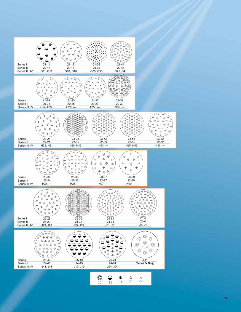
AB
C
D
E
F
G
H
KLMN
PR
S
T
U
V
W
XY
Z a b
cd
e
f
g
h
ijkm
n
p
q
r
s
tu v
w
x
y
zAA
BBCC
DD
EE
FF
GG HH
JJ
KK
LL
MM
NN
PP
Y X
We
Z
a f d V
cUb
TSR
P
N
M
L
K
J H
G
F
E
D
C
B
A
100
9998
97
96
95
94
93
8677
8576
6756
6634
4555
463525
16
2415
7
8
6
54
3
2
1
A
B
C
D
E
FG
H
J
K
L
M
N
P
R
U T
V SX
W
S
PH
F
D
N
BM
AL
K
R
J
G E
C
CONTACT LEGEND
79
1
5131
11
21
61
41
71
t
AB
C
D
E
F
GH
JK
LM
N
PR
S
T
U
VW
X
Y
Z
a
b
cde
f
g
h
i
jk
m
npq
r
s
10 12 16 20 22D
58
71
81
7
1424
3547
7093
104114
121
128
1254
122
115
10594
825948
3625
15
81
FFHH
GG
EEDD
CCBB
AAz
y
xw
vu
t
s
rq
pn
m
j
i
hg
fe
dc
b
a
Z
YX
WV
UT
S
KR
P
N
M
LK J
HG
F
E
D
CB
A
_r_z_h
_x_w
_d_v
_u_t
_a
_b_c
_e
_s
_f
_m_k
_n
_y
_
_
_
XN
PR
S AB
C
AA
T
p
BB
HHGG
Mg
L EE
U
WD
V
E
F
DDFF
J
KH
G
Z
Y
q
CC
A
B
C
DE
F
G
H
J
K
L
A
B
C
D
EF
G
H
J
K
LM
N
P
R
ST
U
V
W X
Y
Z
a
A
B
C
D
E
F
GH
JK
L
M
N
P
R
S
T
UV
W
X
Y
Z
a
b
A
B
C
D
E
F
G
HJ
K
L
M
N
P
R
S
T
U
VW
X
Y
Z
a
b
cd
AB
C
D
E
F
G
HJ
KL
M
N
P
R
S
T
UV
W
XY
Z
a
b
cd
e
f
g
h
i
j
k
m
n
p
q
r
A
B
C
D
E
FG
H
J
K
L
MN
PR
S
T
U
VW
X
Y
Z
a
b
c
d
ef
g
h
j
A
B
C
D
E
F
G
H
JK
L
M
N
P
R
ST
U
V
W
X
Y
Z
a
b
c
de
f
g
h
j
k
l
A
B
C
D
E
F
G
HJ
K
L
M
N
P
R
S
T
U
V
W
X
Y
Zab
c
d
e
f
g h
j
k
l
m
n
A
B
C
D
E
F
GH
J
K
L
M
N
P
R
S
A
B
C
D
E
F
G
H
J
K
L
A BC
D
E
F
G
H
J
KL
M
N
PR
S
T
U
V
W
X
Y
Z a
bc
d
e
f
g
h
k
mn
p
q
r
t
u
vw
x
y
zs JJ
KK
LL
AA
BBCC
DD
EE
FF
GG
HH
AB
C
D
E
F
G
H
J
KL
MN
P
R
S
T
U
V
W
XY
Z
a
b
c
d
ef
g
h
k
m
np
q
r
stu
v
w
x
A B
C
D
E
FGH
J
K
L
M
N P
R
ST
U V
A
B
C
D
E
F
G
HJ
K
L
M
N
P
RS
T
U
VW
X
Y Z
a
21-1120-11
G11, G11
21-1620-16
G16, G16
21-3520-35
G35, G35
21-4120-41
G41, G41
21-2420-24
G24, G24
21-2520-25
G25, ---
21-2720-27
G27, ---
21-3920-39
G39, ---
23-2122-21
H21, H21
23-3522-35
H35, H35
23-5322-53
H53, ---
23-5522-55
H55, H55
23-3222-32
H32, ---
23-3422-34
H34, ---
23-3622-36
H36, ---
23-9722-97
H97, ---
23-9922-99
H99, ---
25-2924-29
J29, J29
25-3524-35
J35, J35
25-6124-61
J61, J61
25-424-4
J4, J4
25-4324-43
J43, J43
25-1924-19
J19, J19
25-2424-24
J24, J24
Series ISeries IISeries III, IV
A
B
C
D
EF
G
HJ
KL
J-11(Series IV Only)
Series ISeries IISeries III, IV
Series ISeries IISeries III, IV
Series ISeries IISeries III, IV
Series ISeries IISeries III, IV
Series ISeries IISeries III, IV
A
D
C
B
E
F
G
HF
E
B
C
D
A
2221
1
65
43
2
1 C A
B
ABE
B
C
D
A1
23
4
567
8
910
11
1213FE
D C
B
A A
B
CD
E
F
G
D
C
B
A
H
G
F
ED
C
B
A
JK
H
G
FE
D
C
BA
E
D C
B
A
C
EG
J R
K
L A
M B
N
D
F
HP
L
S
R
P
U
H F
D
N
BM A
VK
TJ
G
E
C
3121
1
H
F
D
B
M
A
L
KJ
G
E
C
c
ba
Z
YX
W
V
U
TS
R
P
N
M
L
KJ H
G
F
E
D
CB
A AB
C
D
E
FG
HJK
L
M
N
PR
S T
U
VW
X
YZ
55
410
17 25 3240
47
53
5246
39312416
9
3
1
L
K
J
H
G
F
E
D
C
B
A
e
d
c
b
aZ
Y
X
W
VU
TS
R
P
N
M
L
KJ
HG
F
E
D
C
BA
h
j g
fe
d
c
b
a Z
YX
W
VU
TS
R
P
N
M
LK
J HG
F
E
D
C
BA
1
2
3
916
2433 42
5057
63
66
65
64
5851
433425
1710
4
CONTACT LEGEND
22D20161210
A
BC
D
L
S R
PU
H
F
D
N BM
A
K
TJ
G E
C
A
B
C
D
E
F
GH
J
K
L
M
N
P
RS
T
U
V
W
X
Y
Z
a
b
c
d
e
fg
1
2
3
916
2434 4351
5864
67
65
595244
35251710
4
9-988-98A98---
9-358-35A35---
11-210-2B2---
11-410-4B4---
11-510-5B5B5
11-3510-35B35B35
11-9810-98B98B98
11-9910-99B99B99
13-412-4C4C4
13-812-8C8---
13-3512-35C35C35
13-9812-98C98C98
15-514-5D5D5
15-1514-15D15---
15-1814-18D18D18
15-1914-19D19D19
15-3514-35D35D35
15-9714-97D97D97
17-616-6E6E6
17-816-8E8E8
17-2616-26E26E26
17-3516-35E35E35
17-9916-99E99---
19-1118-11F11F11
19-2818-28F28---
19-3218-32F32F32
19-3518-35F35F35
19-3018-30F30---
19-4518-45F45---
Series ISeries IISeries IIISeries IV
Series ISeries IISeries IIISeries IV
Series ISeries IISeries IIISeries IV
Series ISeries IISeries IIISeries IV
Series ISeries IISeries IIISeries IV
AB
C
D
E
F
G
H
KLMN
PR
S
T
U
V
W
XY
Z a b
cd
e
f
g
h
ijkm
n
p
q
r
s
tu v
w
x
y
zAA
BBCC
DD
EE
FF
GG HH
JJ
KK
LL
MM
NN
PP
Y X
We
Z
a f d V
cUb
TSR
P
N
M
L
K
J H
G
F
E
D
C
B
A
100
9998
97
96
95
94
93
8677
8576
6756
6634
4555
463525
16
2415
7
8
6
54
3
2
1
A
B
C
D
E
FG
H
J
K
L
M
N
P
R
U T
V SX
W
S
PH
F
D
N
BM
AL
K
R
J
G E
C
CONTACT LEGEND
79
1
5131
11
21
61
41
71
t
AB
C
D
E
F
GH
JK
LM
N
PR
S
T
U
VW
X
Y
Z
a
b
cde
f
g
h
i
jk
m
npq
r
s
10 12 16 20 22D
58
71
81
7
1424
3547
7093
104114
121
128
1254
122
115
10594
825948
3625
15
81
FFHH
GG
EEDD
CCBB
AAz
y
xw
vu
t
s
rq
pn
m
j
i
hg
fe
dc
b
a
Z
YX
WV
UT
S
KR
P
N
M
LK J
HG
F
E
D
CB
A
_r_z_h
_x_w
_d_v
_u_t
_a
_b_c
_e
_s
_f
_m_k
_n
_y
_
_
_
XN
PR
S AB
C
AA
T
p
BB
HHGG
Mg
L EE
U
WD
V
E
F
DDFF
J
KH
G
Z
Y
q
CC
A
B
C
DE
F
G
H
J
K
L
A
B
C
D
EF
G
H
J
K
LM
N
P
R
ST
U
V
W X
Y
Z
a
A
B
C
D
E
F
GH
JK
L
M
N
P
R
S
T
UV
W
X
Y
Z
a
b
A
B
C
D
E
F
G
HJ
K
L
M
N
P
R
S
T
U
VW
X
Y
Z
a
b
cd
AB
C
D
E
F
G
HJ
KL
M
N
P
R
S
T
UV
W
XY
Z
a
b
cd
e
f
g
h
i
j
k
m
n
p
q
r
A
B
C
D
E
FG
H
J
K
L
MN
PR
S
T
U
VW
X
Y
Z
a
b
c
d
ef
g
h
j
A
B
C
D
E
F
G
H
JK
L
M
N
P
R
ST
U
V
W
X
Y
Z
a
b
c
de
f
g
h
j
k
l
A
B
C
D
E
F
G
HJ
K
L
M
N
P
R
S
T
U
V
W
X
Y
Zab
c
d
e
f
g h
j
k
l
m
n
A
B
C
D
E
F
GH
J
K
L
M
N
P
R
S
A
B
C
D
E
F
G
H
J
K
L
A BC
D
E
F
G
H
J
KL
M
N
PR
S
T
U
V
W
X
Y
Z a
bc
d
e
f
g
h
k
mn
p
q
r
t
u
vw
x
y
zs JJ
KK
LL
AA
BBCC
DD
EE
FF
GG
HH
AB
C
D
E
F
G
H
J
KL
MN
P
R
S
T
U
V
W
XY
Z
a
b
c
d
ef
g
h
k
m
np
q
r
stu
v
w
x
A B
C
D
E
FGH
J
K
L
M
N P
R
ST
U V
A
B
C
D
E
F
G
HJ
K
L
M
N
P
RS
T
U
VW
X
Y Z
a
21-1120-11
G11, G11
21-1620-16
G16, G16
21-3520-35
G35, G35
21-4120-41
G41, G41
21-2420-24
G24, G24
21-2520-25
G25, ---
21-2720-27
G27, ---
21-3920-39
G39, ---
23-2122-21
H21, H21
23-3522-35
H35, H35
23-5322-53
H53, ---
23-5522-55
H55, H55
23-3222-32
H32, ---
23-3422-34
H34, ---
23-3622-36
H36, ---
23-9722-97
H97, ---
23-9922-99
H99, ---
25-2924-29
J29, J29
25-3524-35
J35, J35
25-6124-61
J61, J61
25-424-4
J4, J4
25-4324-43
J43, J43
25-1924-19
J19, J19
25-2424-24
J24, J24
Series ISeries IISeries III, IV
A
B
C
D
EF
G
HJ
KL
J-11(Series IV Only)
Series ISeries IISeries III, IV
Series ISeries IISeries III, IV
Series ISeries IISeries III, IV
Series ISeries IISeries III, IV
Series ISeries IISeries III, IV
AB
C
D
E
F
G
H
KLMN
PR
S
T
U
V
W
XY
Z a b
cd
e
f
g
h
ijkm
n
p
q
r
s
tu v
w
x
y
zAA
BBCC
DD
EE
FF
GG HH
JJ
KK
LL
MM
NN
PP
Y X
We
Z
a f d V
cUb
TSR
P
N
M
L
K
J H
G
F
E
D
C
B
A
100
9998
97
96
95
94
93
8677
8576
6756
6634
4555
463525
16
2415
7
8
6
54
3
2
1
A
B
C
D
E
FG
H
J
K
L
M
N
P
R
U T
V SX
W
S
PH
F
D
N
BM
AL
K
R
J
G E
C
CONTACT LEGEND
79
1
5131
11
21
61
41
71
t
AB
C
D
E
F
GH
JK
LM
N
PR
S
T
U
VW
X
Y
Z
a
b
cde
f
g
h
i
jk
m
npq
r
s
10 12 16 20 22D
58
71
81
7
1424
3547
7093
104114
121
128
1254
122
115
10594
825948
3625
15
81
FFHH
GG
EEDD
CCBB
AAz
y
xw
vu
t
s
rq
pn
m
j
i
hg
fe
dc
b
a
Z
YX
WV
UT
S
KR
P
N
M
LK J
HG
F
E
D
CB
A
_r_z_h
_x_w
_d_v
_u_t
_a
_b_c
_e
_s
_f
_m_k
_n
_y
_
_
_
XN
PR
S AB
C
AA
T
p
BB
HHGG
Mg
L EE
U
WD
V
E
F
DDFF
J
KH
G
Z
Y
q
CC
A
B
C
DE
F
G
H
J
K
L
A
B
C
D
EF
G
H
J
K
LM
N
P
R
ST
U
V
W X
Y
Z
a
A
B
C
D
E
F
GH
JK
L
M
N
P
R
S
T
UV
W
X
Y
Z
a
b
A
B
C
D
E
F
G
HJ
K
L
M
N
P
R
S
T
U
VW
X
Y
Z
a
b
cd
AB
C
D
E
F
G
HJ
KL
M
N
P
R
S
T
UV
W
XY
Z
a
b
cd
e
f
g
h
i
j
k
m
n
p
q
r
A
B
C
D
E
FG
H
J
K
L
MN
PR
S
T
U
VW
X
Y
Z
a
b
c
d
ef
g
h
j
A
B
C
D
E
F
G
H
JK
L
M
N
P
R
ST
U
V
W
X
Y
Z
a
b
c
de
f
g
h
j
k
l
A
B
C
D
E
F
G
HJ
K
L
M
N
P
R
S
T
U
V
W
X
Y
Zab
c
d
e
f
g h
j
k
l
m
n
A
B
C
D
E
F
GH
J
K
L
M
N
P
R
S
A
B
C
D
E
F
G
H
J
K
L
A BC
D
E
F
G
H
J
KL
M
N
PR
S
T
U
V
W
X
Y
Z a
bc
d
e
f
g
h
k
mn
p
q
r
t
u
vw
x
y
zs JJ
KK
LL
AA
BBCC
DD
EE
FF
GG
HH
AB
C
D
E
F
G
H
J
KL
MN
P
R
S
T
U
V
W
XY
Z
a
b
c
d
ef
g
h
k
m
np
q
r
stu
v
w
x
A B
C
D
E
FGH
J
K
L
M
N P
R
ST
U V
A
B
C
D
E
F
G
HJ
K
L
M
N
P
RS
T
U
VW
X
Y Z
a
21-1120-11
G11, G11
21-1620-16
G16, G16
21-3520-35
G35, G35
21-4120-41
G41, G41
21-2420-24
G24, G24
21-2520-25
G25, ---
21-2720-27
G27, ---
21-3920-39
G39, ---
23-2122-21
H21, H21
23-3522-35
H35, H35
23-5322-53
H53, ---
23-5522-55
H55, H55
23-3222-32
H32, ---
23-3422-34
H34, ---
23-3622-36
H36, ---
23-9722-97
H97, ---
23-9922-99
H99, ---
25-2924-29
J29, J29
25-3524-35
J35, J35
25-6124-61
J61, J61
25-424-4
J4, J4
25-4324-43
J43, J43
25-1924-19
J19, J19
25-2424-24
J24, J24
Series ISeries IISeries III, IV
A
B
C
D
EF
G
HJ
KL
J-11(Series IV Only)
Series ISeries IISeries III, IV
Series ISeries IISeries III, IV
Series ISeries IISeries III, IV
Series ISeries IISeries III, IV
Series ISeries IISeries III, IV
51

52
Shell Size and Insert Arrangements Number of PinsMS Series I MS Series II D38999 Series III Service Rating 22D 20 16 12
9-35 8-35 A35 M 69-98 8-98 A98 I 311-2 10-2 B2 I 211-4 10-4 B4 I 411-5 10-5 B5 I 5
11-35 10-35 B35 M 1311-98 10-98 B98 I 611-99 10-99 B99 I 713-4 12-4 C4 I 413-8 12-8 C8 I 813-35 12-35 C35 M 2213-98 12-98 C98 I 1015-5 14-5 D5 II 515-15 14-15 D15 I 14 115-18 14-18 D18 I 1815-19 14-19 D19 I 1915-35 14-35 D35 M 3715-97 14-97 D97 I 8 417-6 16-6 E6 I 617-8 16-8 E8 II 8
17-26 16-26 E26 I 2617-35 16-35 E35 M 5517-99 16-99 E99 I 21 219-11 18-11 F11 II 1119-28 18-28 F28 I 26 219-30 18-30 F30 I 29 119-32 18-32 F32 I 3219-35 18-35 F35 M 6619-45 18-45 F45 M 6721-11 20-11 G11 I 1121-16 20-16 G16 II 1621-24 20-24 G24 I 2421-25 20-25 G25 I 2521-27 20-27 G27 I 2721-35 20-35 G35 M 7921-39 20-39 G39 I 37 221-41 20-41 G41 I 4123-21 22-21 H21 II 2123-32 22-32 H32 I 3223-34 22-34 H34 I 3423-35 22-35 H35 M 10023-36 22-36 H36 I 36
MIL-DTL-38999 Series I, II, III, and IV Connectors Layouts and Pin Counts

53
23-53 22-53 H53 I 5323-55 22-55 H55 I 5523-97 22-97 H97 I 1623-99 22-99 H99 II 1125-4 24-4 J4 I 48 8
25-19 24-19 J19 I 1925-24 24-24 J24 I 12 1225-29 24-29 J29 I 2925-35 24-35 J35 M 12825-43 24-43 J43 I 23 2025-61 24-61 J61 I 61
Shell Size / Insert
ArrangementsNumber of Pins
D38999 Series IV 22D 20 16 12 10B5 5
B35 13
B98 6
B99 7
C4 4
C35 22
C98 10
D5 5
D18 18
D19 37 19
D35
D97 8 4
E6 6
E8 8
E26 26
E35 55
F11 11
Shell Size / Insert
ArrangementsNumber of Pins
D38999 Series IV 22D 20 16 12 10G41 41
H21 21
H35 100
H55 55
J4 48 8
J11 2 9
J19 19
J24 12 12
J29 29
J35 128
J43 23 20
J61 61
F32 32
F35 66
G11 11
G16 16
G35 79

54
Product ApplicationsGlenair Sav-Con® Connector Savers are designed
to protect connectors that are subject to repeated mating and unmating cycles. Sav-Con® Connector Savers prevent costly repair or replacement of expensive connectors and cables while preserving the quality and integrity of connector performance. Sav-Con® Connector Savers take the abuse of repeated connection cycles instead of “black box” or other equipment connectors. Equipment connectors that are mated and unmated frequently during manufacturing,
check-out phases and environmental test programs can be protected by Glenair Sav-Con® Connector Savers at considerable savings in time and money.
Glenair Sav-Con® Connector Savers feature one-piece, non-removable pin/socket contacts for maximum reliability and minimum effect on circuit resistance. Each Glenair Sav-Con® Connector Saver series meets the same durability requirements as the Military Specification series with which it mates. The mating portions of the pin-and-socket contacts are in strict compliance with the applicable Military Specification contacts used in each connector series.
The Smart Solution for Preventing Contact Damage and Extending the Service Life of Cable and Box Assemblies
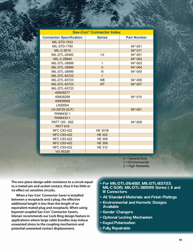
* 0 = General Duty 1 = Environmental 2 = High Reliability
55
Sav-Con® Connector IndexConnector Specification Series Part Number
MIL-STD-1533MIL-STD-1760 94*-021
MIL-C-5015 94*-011MIL-DTL-26482 I-II 94*-001
MIL-C-28840 94*-002MIL-DTL-38999 I 94*-003MIL-DTL-38999 II 94*-004MIL-DTL-38999 III 94*-005MIL-DTL-83723 IMIL-DTL-83723 IIIB 94*-006MIL-DTL-83723 IIIT 94*-007MIL-DTL-83723
40M3827740M38298 94*-01040M39569LN29504
LN 29729 (SJT) 94*-001PAN6432-1PAN6433-1
PATT 105 - 602 94*-009PATT 616
NFC C93-422 HE 301BNFC C93-422 HE 302NFC C93-422 HE 308NFC C93-422 HE 309NFC C93-422 HE 312
VG 95328
The one-piece design adds resistance to a circuit equal to a mated pin and socket contact, thus it has little or no effect on sensitive circuits.
When a Sav-Con® Connector Saver is installed between a receptacle and a plug, the effective additional length is less than the length of an equivalent mated plug and receptacle. When using bayonet coupled Sav-Con® Connector Savers, Glenair recommends our Lock Ring design feature in applications where large cable bundles may induce unwanted stress to the coupling mechanism and potential unwanted contact displacement.
� For MIL-DTL-26482, MIL-DTL-83723, MIL-C-5015, MIL-DTL-38999 Series I, II and III Connectors � All Standard Materials and Finish Platings � Environmental and Hermetic Designs Available � Gender Changers � Optional Locking Mechanism � Keyed Polarization � Fully Repairable

56
High Speed Connector Application WorksheetGlenair excels in the design and fabrication of high-speed (RF) connectors equipped with coax, twinax,
quadrax, and other matched-impedance, shielded cartridge contacts. This connector specification worksheet is designed to capture essential high-speed connector application details at the onset of the specification and design process.
Cable Type
M17 _____________________
RG ______________________
Raychem _________________
Gore _____________________
Tensolite _________________
Other ____________________
Contact Name ______________________________________________
Phone ____________________________________________________
Email _____________________________________________________
Program __________________________________________________
Application Environment ______________________________________
Ethernet Protocol
10BaseT____
100BaseT____
1000BaseT____
10GBaseT____
Ground Plane
Yes____ No____
Connector Series
38999____ I, II, III, IV____
26482____
Other __________________
Arrangement ____________
Impedance (ohm)
50 ________
75 ________
100 _______
150 _______
Other _____
Contact Size
12 ________
16 ________
20 ________
22 ________
Contact Type
Coax____
Twinax____
Concentric Twinax____
Quadrax____
Other Information
Mating Contact
AS39029/____-____