environmental control system - public … · environmental control system navy model tav-8b ......
TRANSCRIPT
A1-AV8BC-410-1001 February 1990
Change 7 - 15 May 2004
TECHNICAL MANUAL
ORGANIZATIONAL MAINTENANCE
PRINCIPLES OF OPERATION
ENVIRONMENTAL CONTROL SYSTEM
NAVY MODEL
TAV-8B
162747 AND UP
DISTRIBUTION STATEMENT C. Distribution authorized to U.S. Government agencies
and their contractors to protect publications required for official use or for
administrative or operational purposes only, determined on 15 May 1999. Other
requests for this document shall be referred to Commanding Officer, Naval Air
Technical Data and Engineering Service Command, Naval Air Station North Island
P.O. Box 357031, Building 90 Distribution, San Diego, CA 92135-7031.
DESTRUCTION NOTICE - For unclassified, limited documents, destroy by any method
that will prevent disclosure of contents or reconstruction of the document.
Published by Direction of the
Commander, Naval Air Systems Command
NATEC ELECTRONIC MANUAL
0801LP1033202
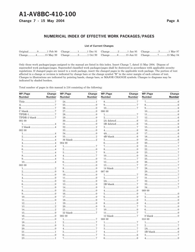
NUMERICAL INDEX OF EFFECTIVE WORK PACKAGES/PAGES
List of Current Changes
Original.............0.............1 Feb 90 Change............1............1 Dec 91 Change ............2 ............1 Jan 95 Change.............3 .............1 Mar 97Change............4............15 May 99 Change ............5 ............1 Oct 99 Change...........6...........15 Jun 03 Change............7............15 May 04
Only those work packages/pages assigned to the manual are listed in this index. Insert Change 7, dated 15 May 2004. Dispose ofsuperseded work packages/pages. Superseded classified work packages/pages shall be destroyed in accordance with applicable securityregulations. If changed pages are issued to a work package, insert the changed pages in the applicable work package. The portion of textaffected in a change or revision is indicated by change bars or the change symbol “R” in the outer margin of each column of text.Changes to illustrations are indicated by pointing hands, change bars, or MAJOR CHANGE symbols. Changes to diagrams may beindicated by shaded borders.
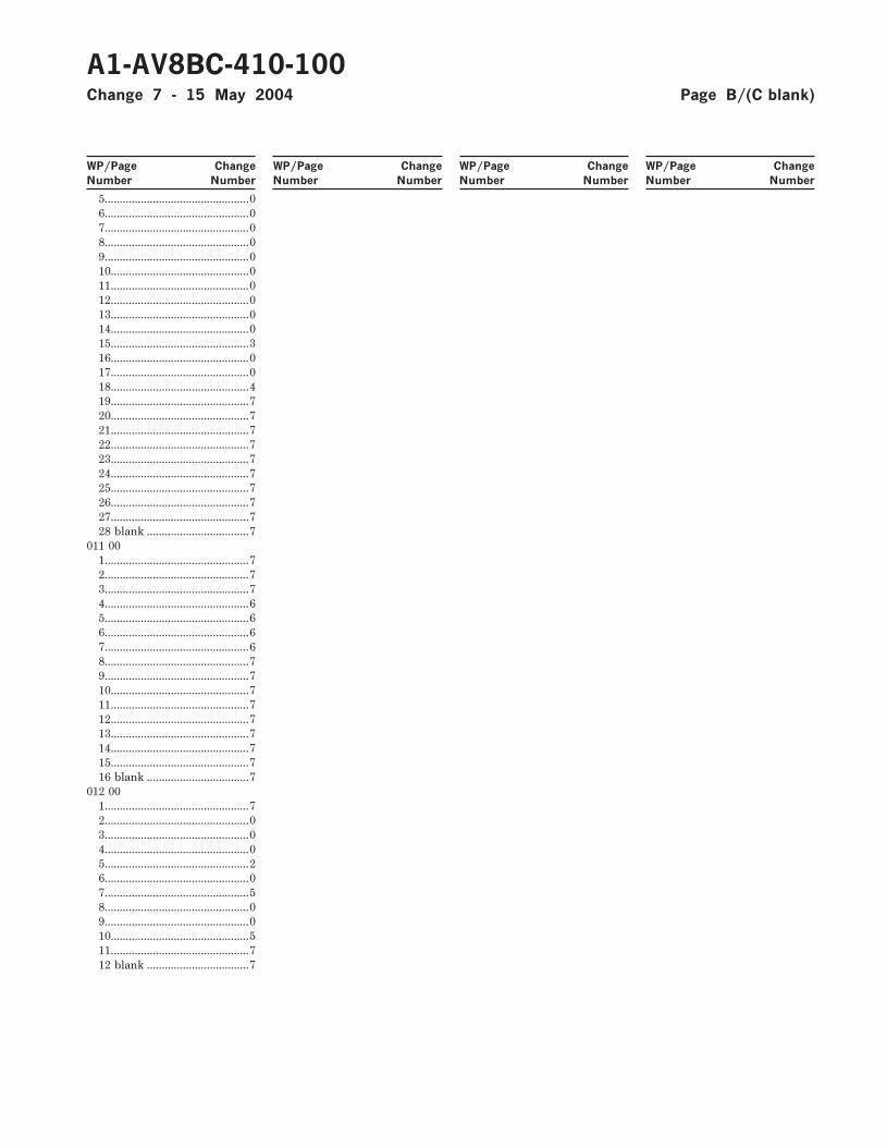
Total number of pages in this manual is 216 consisting of the following:
WP/Page Change WP/Page Change WP/Page Change WP/Page Change
Number Number Number Number Number Number Number NumberNumber
Title .............................................7A...................................................7B...................................................7C blank........................................7TPDR-1.......................................7TPDR-2 blank ...........................7001 00
1................................................42 blank ....................................4
002 001................................................42................................................43................................................44................................................45................................................46................................................47................................................48................................................49................................................410..............................................4
003 001................................................22................................................03................................................04................................................05................................................06................................................07................................................08................................................09................................................010..............................................011..............................................012..............................................113..............................................214..............................................215..............................................016..............................................017..............................................018..............................................119..............................................020..............................................021..............................................122..............................................023..............................................1
24..............................................125..............................................026..............................................027..............................................028..............................................029..............................................030..............................................231..............................................032..............................................233..............................................034..............................................035..............................................236 blank ..................................2
004 001................................................72................................................03................................................74................................................75................................................06................................................07................................................08................................................09................................................010..............................................011..............................................012..............................................013..............................................014..............................................015..............................................016..............................................017..............................................018..............................................019..............................................020..............................................021..............................................722 blank ..................................7
005 001................................................72................................................73................................................74................................................75................................................76................................................77................................................7
8................................................79................................................710..............................................7
006 001................................................72................................................72A deleted...............................62B deleted...............................63................................................74................................................64A.............................................64B blank..................................65................................................06................................................07................................................08................................................09................................................010..............................................011..............................................712..............................................013..............................................714 blank ..................................7
007 001................................................72................................................72A.............................................72B blank..................................73................................................04................................................05................................................06................................................07................................................08................................................09................................................710..............................................011..............................................712 blank ..................................7
008 001................................................72................................................73................................................74................................................75................................................66................................................6
7................................................68................................................69................................................610..............................................611..............................................612..............................................613..............................................614..............................................615..............................................616..............................................617..............................................618..............................................619..............................................620..............................................721..............................................722..............................................723..............................................724..............................................725..............................................726..............................................727..............................................728..............................................729..............................................730..............................................731..............................................732..............................................733..............................................734..............................................7
009 001................................................02................................................03................................................04................................................05................................................06................................................07................................................08 blank ....................................0
010 001................................................72................................................72A.............................................62B blank..................................63................................................74................................................0
A1-AV8BC-410-100Change 7 - 15 May 2004 Page A
5................................................06................................................07................................................08................................................09................................................010..............................................011..............................................012..............................................013..............................................014..............................................015..............................................316..............................................017..............................................018..............................................419..............................................720..............................................721..............................................722..............................................723..............................................724..............................................725..............................................726..............................................727..............................................728 blank ..................................7
011 001................................................72................................................73................................................74................................................65................................................66................................................67................................................68................................................79................................................710..............................................711..............................................712..............................................713..............................................714..............................................715..............................................716 blank ..................................7
012 001................................................72................................................03................................................04................................................05................................................26................................................07................................................58................................................09................................................010..............................................511..............................................712 blank ..................................7
A1-AV8BC-410-100Change 7 - 15 May 2004 Page B/(C blank)
WP/Page Change WP/Page Change WP/Page Change WP/Page Change
Number Number Number Number Number Number Number Number

LIST OF TECHNICAL PUBLICATION DEFICIENCY REPORTS INCORPORATED
ORGANIZATIONAL MAINTENANCE
PRINCIPLES OF OPERATION
ENVIRONMENTAL CONTROL SYSTEM
This WP supersedes TPDR WP, dated 15 June 2003.
1. Deficiencies identified in this Technical Manual shall be submitted via OPNAV 4790/66 and forwarded toDefense Contract Management Command/Central Technical Manual Control Unit (DCMC/CTMCU),McDonnell Douglas Corporation, P.O. Box 516, St. Louis, MO 63166-0516.
2. The TPDRs listed below have been incorporated in this issue.
IDENTIFICATION NUMBER/
QA SEQUENCE NUMBERLOCATION
NONE
A1-AV8BC-410-100 TPDR-1Change 7 - 15 May 2004 (TPDR-2 blank)

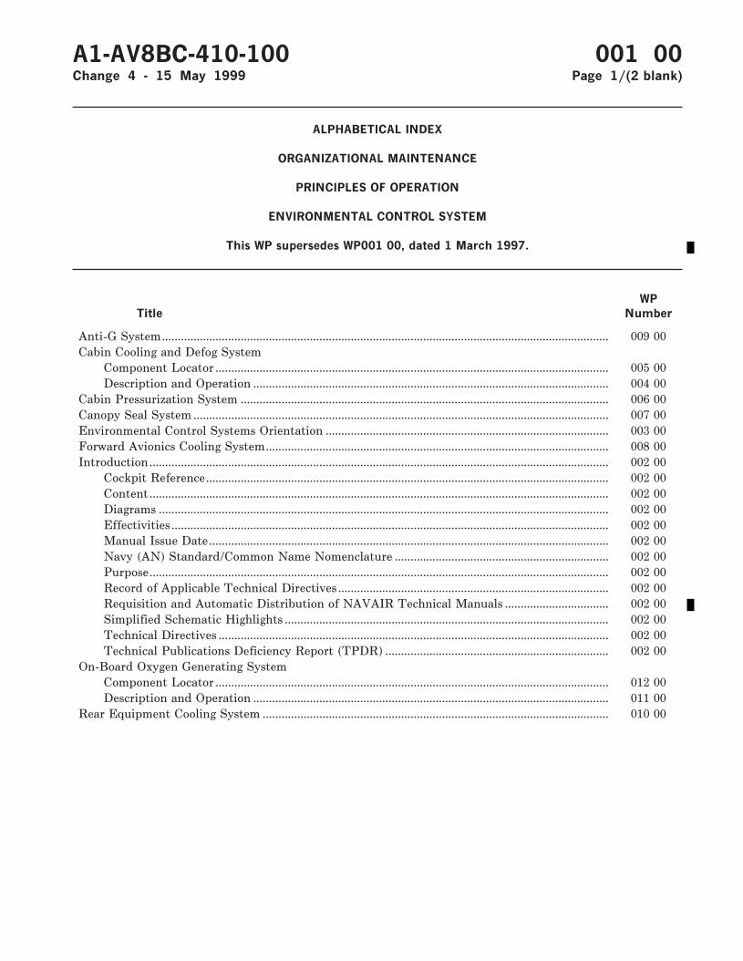
ALPHABETICAL INDEX
ORGANIZATIONAL MAINTENANCE
PRINCIPLES OF OPERATION
ENVIRONMENTAL CONTROL SYSTEM
This WP supersedes WP001 00, dated 1 March 1997.
Title
WP
Number
Anti-G System.............................................................................................................................................. 009 00Cabin Cooling and Defog System
Component Locator ............................................................................................................................. 005 00Description and Operation ................................................................................................................. 004 00
Cabin Pressurization System ..................................................................................................................... 006 00Canopy Seal System .................................................................................................................................... 007 00Environmental Control Systems Orientation .......................................................................................... 003 00Forward Avionics Cooling System............................................................................................................. 008 00Introduction.................................................................................................................................................. 002 00
Cockpit Reference................................................................................................................................ 002 00Content.................................................................................................................................................. 002 00Diagrams ............................................................................................................................................... 002 00Effectivities ........................................................................................................................................... 002 00Manual Issue Date............................................................................................................................... 002 00Navy (AN) Standard/Common Name Nomenclature .................................................................... 002 00Purpose.................................................................................................................................................. 002 00Record of Applicable Technical Directives ...................................................................................... 002 00Requisition and Automatic Distribution of NAVAIR Technical Manuals ................................. 002 00Simplified Schematic Highlights ....................................................................................................... 002 00Technical Directives ............................................................................................................................ 002 00Technical Publications Deficiency Report (TPDR) ....................................................................... 002 00
On-Board Oxygen Generating SystemComponent Locator ............................................................................................................................. 012 00Description and Operation ................................................................................................................. 011 00
Rear Equipment Cooling System .............................................................................................................. 010 00
A1-AV8BC-410-100 001 00Change 4 - 15 May 1999 Page 1/(2 blank)

INTRODUCTION
ORGANIZATIONAL MAINTENANCE
PRINCIPLES OF OPERATION
ENVIRONMENTAL CONTROL SYSTEM
This WP supersedes WP002 00, dated 1 March 1997.
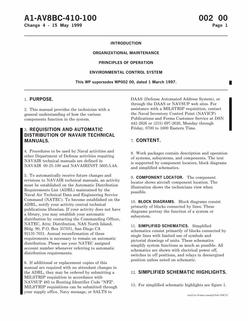
1. PURPOSE.
2. This manual provides the technician with ageneral understanding of how the variouscomponents function in the system.
3. REQUISITION AND AUTOMATICDISTRIBUTION OF NAVAIR TECHNICALMANUALS.
4. Procedures to be used by Naval activities andother Department of Defense activities requiringNAVAIR technical manuals are defined inNAVAIR 00-25-100 and NAVAIRINST 5605.5.4A.
5. To automatically receive future changes andrevisions to NAVAIR technical manuals, an activitymust be established on the Automatic DistributionRequirements List (ADRL) maintained by theNaval Air Technical Data and Engineering ServiceCommand (NATEC). To become established on theADRL, notify your activity central technicalpublications librarian. If your activity does not havea library, you may establish your automaticdistribution by contacting the Commanding Officer,NATEC, Attn: Distribution, NAS North Island,Bldg. 90, P.O. Box 357031, San Diego CA92135-7031. Annual reconfirmation of theserequirements is necessary to remain on automaticdistribution. Please use your NATEC assignedaccount number whenever referring to automaticdistribution requirements.
6. If additional or replacement copies of thismanual are required with no attendant changes inthe ADRL, they may be ordered by submitting aMILSTRIP requisition in accordance withNAVSUP 485 to Routing Identifier Code ″NFZ″.MILSTRIP requisitions can be submitted throughyour supply office, Navy message, or SALTS to
DAAS (Defense Automated Address System), orthrough the DAAS or NAVSUP web sites. Forassistance with a MILSTRIP requisition, contactthe Naval Inventory Control Point (NAVICP)Publications and Forms Customer Service at DSN442-2626 or (215) 697-2626, Monday throughFriday, 0700 to 1600 Eastern Time.
7. CONTENT.
8. Work packages contain description and operationof systems, subsystems, and components. The textis supported by component locators, block diagramsand simplified schematics.
9. COMPONENT LOCATOR. The componentlocator shows aircraft component location. Theillustration shows the technicians view whenpossible.
10. BLOCK DIAGRAMS. Block diagrams consistprimarily of blocks connected by lines. Thesediagrams portray the function of a system orsubsystem.
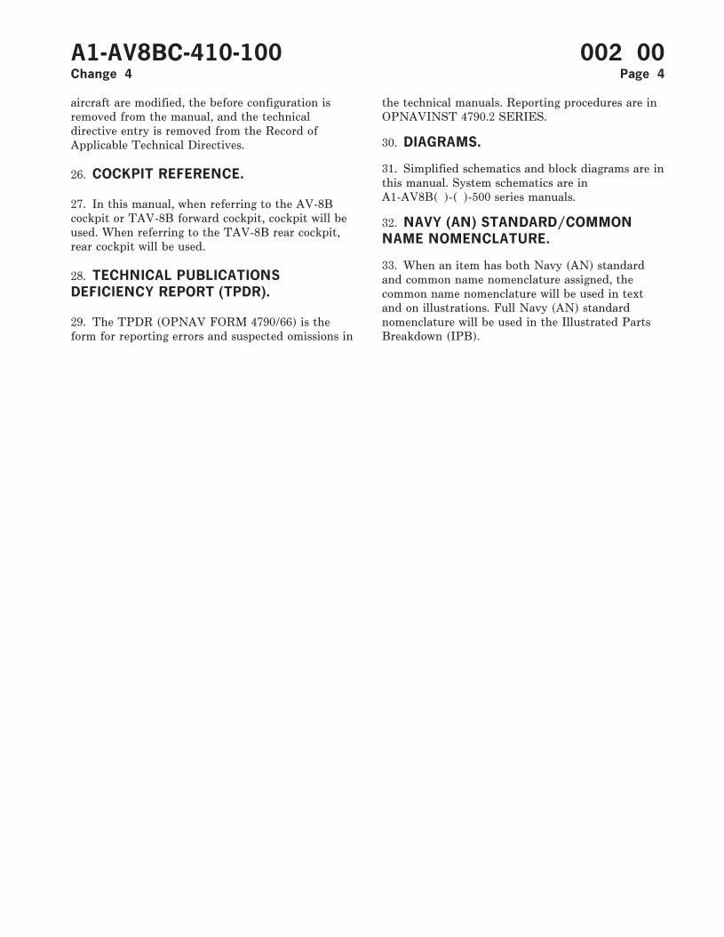
11. SIMPLIFIED SCHEMATICS. Simplifiedschematics consist primarily of blocks connected bysingle lines with limited use of symbols andpictorial drawings of units. These schematicssimplify system functions as much as possible. Allschematics are shown with electrical power off,switches in off positions, and relays in deenergizedposition unless noted on schematic.
12. SIMPLIFIED SCHEMATIC HIGHLIGHTS.
13. For simplified schematic highlights see figure 1.
A1-AV8BC-410-100 002 00Change 4 - 15 May 1999 Page 1
text2/av-8/misc/comwp2/hr6-100C15
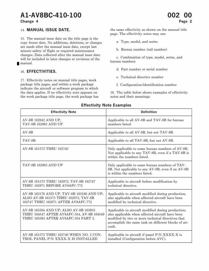
14. MANUAL ISSUE DATE.
15. The manual issue date on the title page is thecopy freeze date. No additions, deletions, or changesare made after the manual issue date, except lastminute safety of flight or required maintenancechanges. Data collected after the manual issue datewill be included in later changes or revisions of themanual.
16. EFFECTIVITIES.
17. Effectivity notes on manual title pages, workpackage title pages, and within a work packageindicate the aircraft or software program to whichthe data applies. If no effectivity note appears onthe work package title page, the work package has
the same effectivity as shown on the manual titlepage. The effectivity notes may use:
a. Type, model, and series
b. Bureau number (tail number)
c. Combination of type, model, series, andbureau numbers
d. Part number or serial number
e. Technical directive number
f. Configuration/identification number
18. The table below shows examples of effectivitynotes and their meanings:
Effectivity Note Examples
Effectivity Note Definition
AV-8B 162942 AND UP,TAV-8B 162963 AND UP
Applicable to all AV-8B and TAV-8B for bureaunumbers listed.
AV-8B Applicable to all AV-8B, but not TAV-8B.
TAV-8B Applicable to all TAV-8B, but not AV-8B.
AV-8B 161573 THRU 162745 Only applicable to some bureau numbers of AV-8B.Not applicable to any TAV-8B, even if a TAV-8B iswithin the numbers listed.
TAV-8B 162963 AND UP Only applicable to some bureau numbers of TAV-8B. Not applicable to any AV-8B, even if an AV-8Bis within the numbers listed.
AV-8B 161573 THRU 162973, TAV-8B 162747THRU 162971 BEFORE AV8AFC-772
Applicable to aircraft before modification bytechnical directive.
AV-8B 163176 AND UP, TAV-8B 163180 AND UP;ALSO AV-8B 161573 THRU 162973, TAV-8B162747 THRU 162971 AFTER AV8AFC-772
Applicable to aircraft modified during production;also applicable when affected aircraft have beenmodified by technical directive.
AV-8B 165384 AND UP; ALSO AV-8B 163853THRU 164547 AFTER AV8AFC-354, AV-8B 164549THRU 165383 AFTER AV8AFC-354 PART 2.
Applicable to aircraft modified during production;also applicable when affected aircraft have beenmodified by two or more technical directives thataccomplish the same task on different blocks of air-craft.
AV-8B 161573 THRU 162746 WHEN NO. 2 CON-TROL PANEL P/N XXXX-X IS INSTALLED
Applicable to aircraft if panel P/N XXXX-X isinstalled (Configuration before AVC).
A1-AV8BC-410-100 002 00Change 4 Page 2
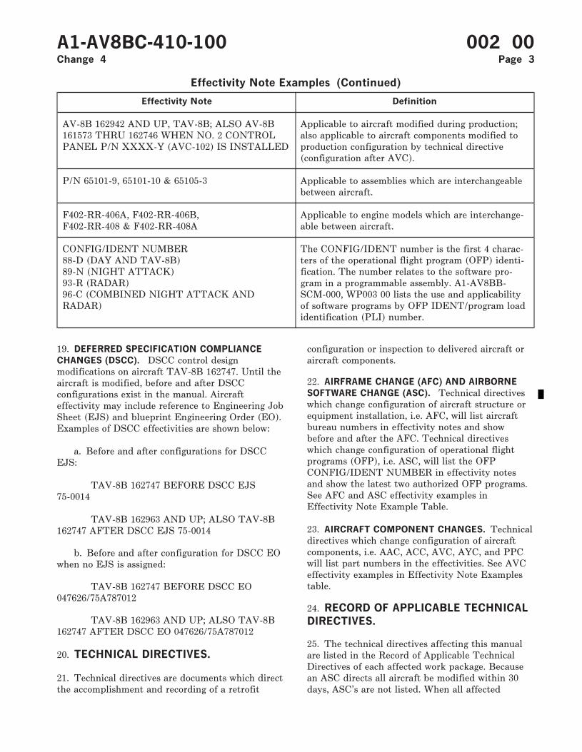
Effectivity Note Examples (Continued)
Effectivity Note Definition
AV-8B 162942 AND UP, TAV-8B; ALSO AV-8B161573 THRU 162746 WHEN NO. 2 CONTROLPANEL P/N XXXX-Y (AVC-102) IS INSTALLED
Applicable to aircraft modified during production;also applicable to aircraft components modified toproduction configuration by technical directive(configuration after AVC).
P/N 65101-9, 65101-10 & 65105-3 Applicable to assemblies which are interchangeablebetween aircraft.
F402-RR-406A, F402-RR-406B,F402-RR-408 & F402-RR-408A
Applicable to engine models which are interchange-able between aircraft.
CONFIG/IDENT NUMBER88-D (DAY AND TAV-8B)89-N (NIGHT ATTACK)93-R (RADAR)96-C (COMBINED NIGHT ATTACK ANDRADAR)
The CONFIG/IDENT number is the first 4 charac-ters of the operational flight program (OFP) identi-fication. The number relates to the software pro-gram in a programmable assembly. A1-AV8BB-SCM-000, WP003 00 lists the use and applicabilityof software programs by OFP IDENT/program loadidentification (PLI) number.
19. DEFERRED SPECIFICATION COMPLIANCE
CHANGES (DSCC). DSCC control designmodifications on aircraft TAV-8B 162747. Until theaircraft is modified, before and after DSCCconfigurations exist in the manual. Aircrafteffectivity may include reference to Engineering JobSheet (EJS) and blueprint Engineering Order (EO).Examples of DSCC effectivities are shown below:
a. Before and after configurations for DSCCEJS:
TAV-8B 162747 BEFORE DSCC EJS75-0014
TAV-8B 162963 AND UP; ALSO TAV-8B162747 AFTER DSCC EJS 75-0014
b. Before and after configuration for DSCC EOwhen no EJS is assigned:
TAV-8B 162747 BEFORE DSCC EO047626/75A787012
TAV-8B 162963 AND UP; ALSO TAV-8B162747 AFTER DSCC EO 047626/75A787012
20. TECHNICAL DIRECTIVES.
21. Technical directives are documents which directthe accomplishment and recording of a retrofit
configuration or inspection to delivered aircraft oraircraft components.
22. AIRFRAME CHANGE (AFC) AND AIRBORNE
SOFTWARE CHANGE (ASC). Technical directiveswhich change configuration of aircraft structure orequipment installation, i.e. AFC, will list aircraftbureau numbers in effectivity notes and showbefore and after the AFC. Technical directiveswhich change configuration of operational flightprograms (OFP), i.e. ASC, will list the OFPCONFIG/IDENT NUMBER in effectivity notesand show the latest two authorized OFP programs.See AFC and ASC effectivity examples inEffectivity Note Example Table.
23. AIRCRAFT COMPONENT CHANGES. Technicaldirectives which change configuration of aircraftcomponents, i.e. AAC, ACC, AVC, AYC, and PPCwill list part numbers in the effectivities. See AVCeffectivity examples in Effectivity Note Examplestable.
24. RECORD OF APPLICABLE TECHNICALDIRECTIVES.
25. The technical directives affecting this manualare listed in the Record of Applicable TechnicalDirectives of each affected work package. Becausean ASC directs all aircraft be modified within 30days, ASC’s are not listed. When all affected
A1-AV8BC-410-100 002 00Change 4 Page 3
aircraft are modified, the before configuration isremoved from the manual, and the technicaldirective entry is removed from the Record ofApplicable Technical Directives.
26. COCKPIT REFERENCE.
27. In this manual, when referring to the AV-8Bcockpit or TAV-8B forward cockpit, cockpit will beused. When referring to the TAV-8B rear cockpit,rear cockpit will be used.
28. TECHNICAL PUBLICATIONSDEFICIENCY REPORT (TPDR).
29. The TPDR (OPNAV FORM 4790/66) is theform for reporting errors and suspected omissions in
the technical manuals. Reporting procedures are inOPNAVINST 4790.2 SERIES.
30. DIAGRAMS.
31. Simplified schematics and block diagrams are inthis manual. System schematics are inA1-AV8B( )-( )-500 series manuals.
32. NAVY (AN) STANDARD/COMMONNAME NOMENCLATURE.
33. When an item has both Navy (AN) standardand common name nomenclature assigned, thecommon name nomenclature will be used in textand on illustrations. Full Navy (AN) standardnomenclature will be used in the Illustrated PartsBreakdown (IPB).
A1-AV8BC-410-100 002 00Change 4 Page 4
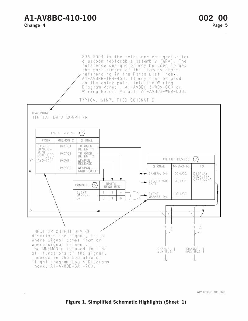
Figure 1. Simplified Schematic Highlights (Sheet 1)
A1-AV8BC-410-100 002 00Change 4 Page 5
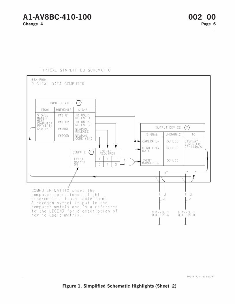
Figure 1. Simplified Schematic Highlights (Sheet 2)
A1-AV8BC-410-100 002 00Change 4 Page 6
Figure 1. Simplified Schematic Highlights (Sheet 3)
A1-AV8BC-410-100 002 00Change 4 Page 7

Figure 1. Simplified Schematic Highlights (Sheet 4)
A1-AV8BC-410-100 002 00Change 4 Page 8
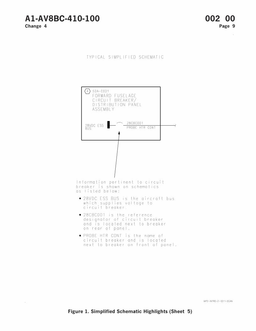
Figure 1. Simplified Schematic Highlights (Sheet 5)
A1-AV8BC-410-100 002 00Change 4 Page 9
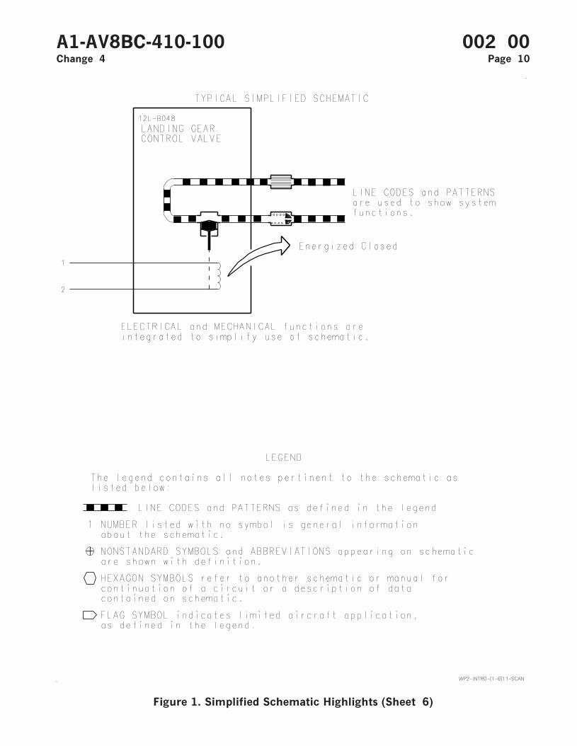
Figure 1. Simplified Schematic Highlights (Sheet 6)
A1-AV8BC-410-100 002 00Change 4 Page 10
ORGANIZATIONAL MAINTENANCE
PRINCIPLES OF OPERATION
ENVIRONMENTAL CONTROL SYSTEM ORIENTATION
ENVIRONMENTAL CONTROL SYSTEM
Reference Material
None
Alphabetical Index
Subject Page No.
Environmental Control System Orientation, Figure 1 .......................................................................... 2Forward Fuselage Environmental Control System Flow Diagram, Figure 2...................................... 15On-Board Oxygen Generating System Flow Diagram, Figure 4 .......................................................... 30Rear Equipment Cooling System Flow Diagram, Figure 3................................................................... 25
Record of Applicable Technical Directives
None
A1-AV8BC-410-100 003 00Change 2 - 1 January 1995 Page 1
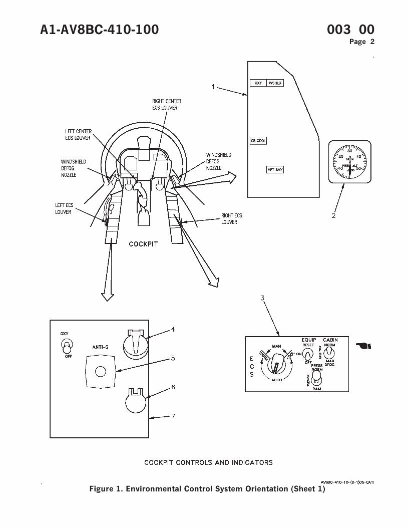
Figure 1. Environmental Control System Orientation (Sheet 1)
A1-AV8BC-410-100 003 00Page 2
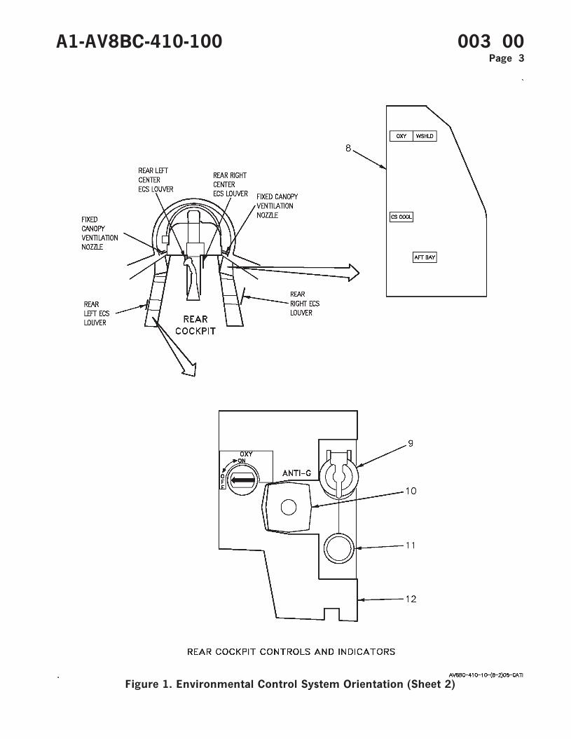
Figure 1. Environmental Control System Orientation (Sheet 2)
A1-AV8BC-410-100 003 00Page 3
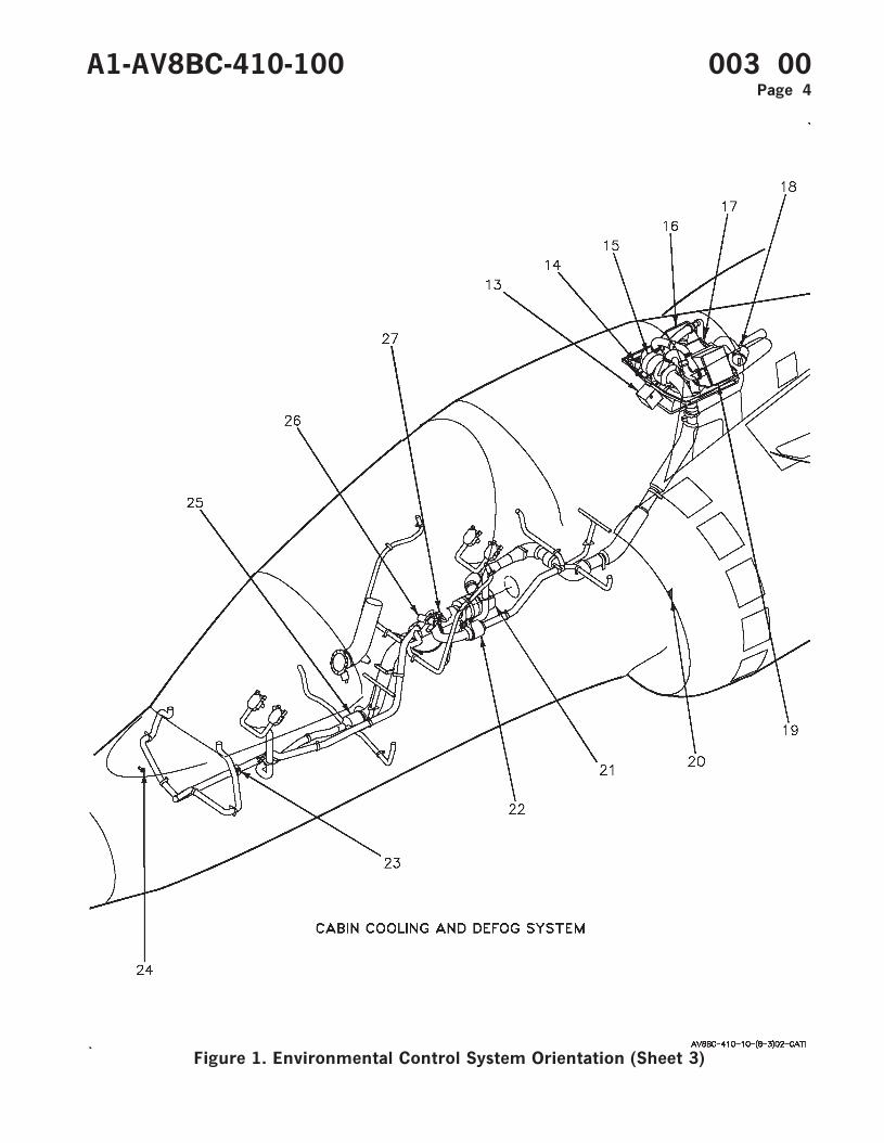
Figure 1. Environmental Control System Orientation (Sheet 3)
A1-AV8BC-410-100 003 00Page 4
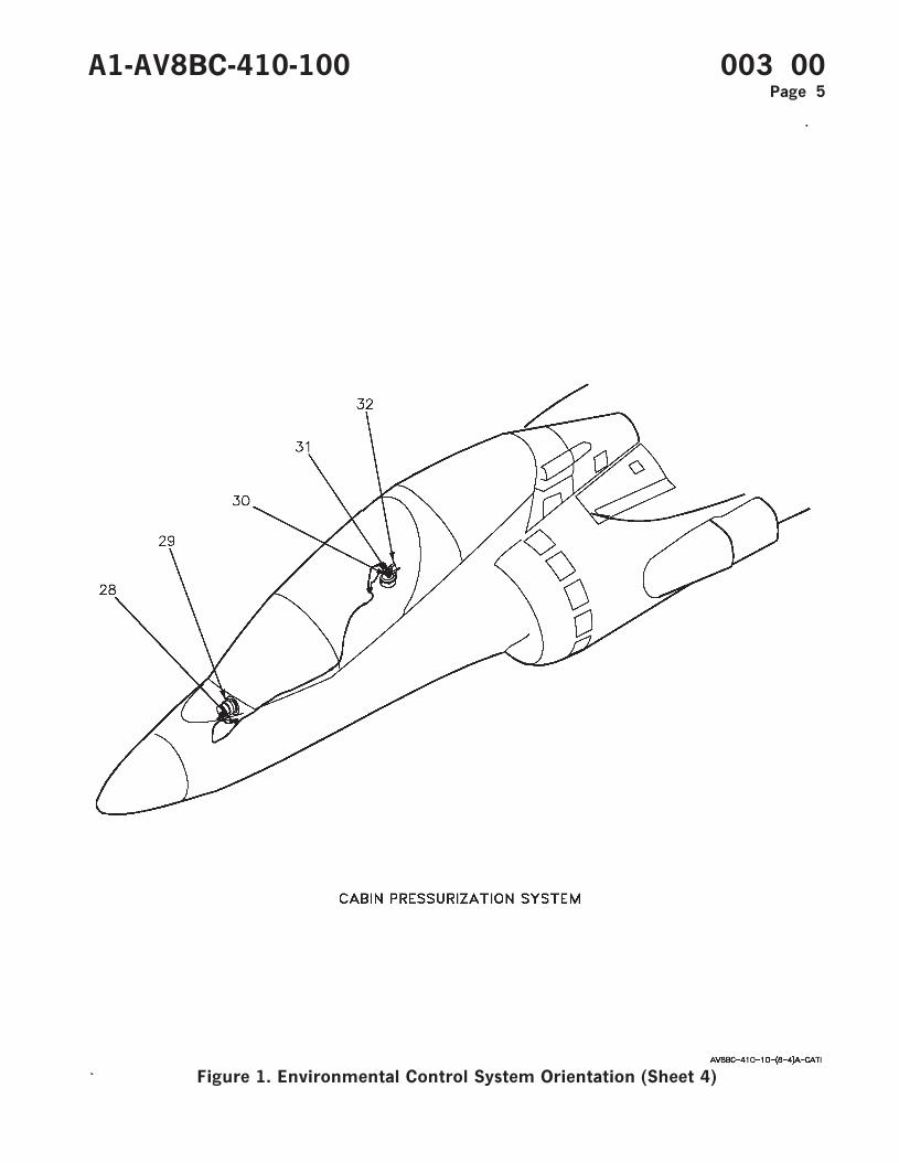
Figure 1. Environmental Control System Orientation (Sheet 4)
A1-AV8BC-410-100 003 00Page 5
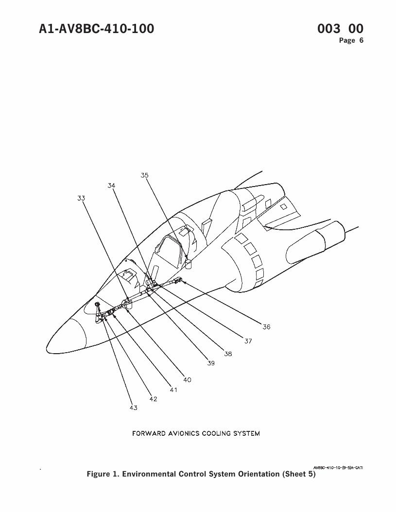
Figure 1. Environmental Control System Orientation (Sheet 5)
A1-AV8BC-410-100 003 00Page 6
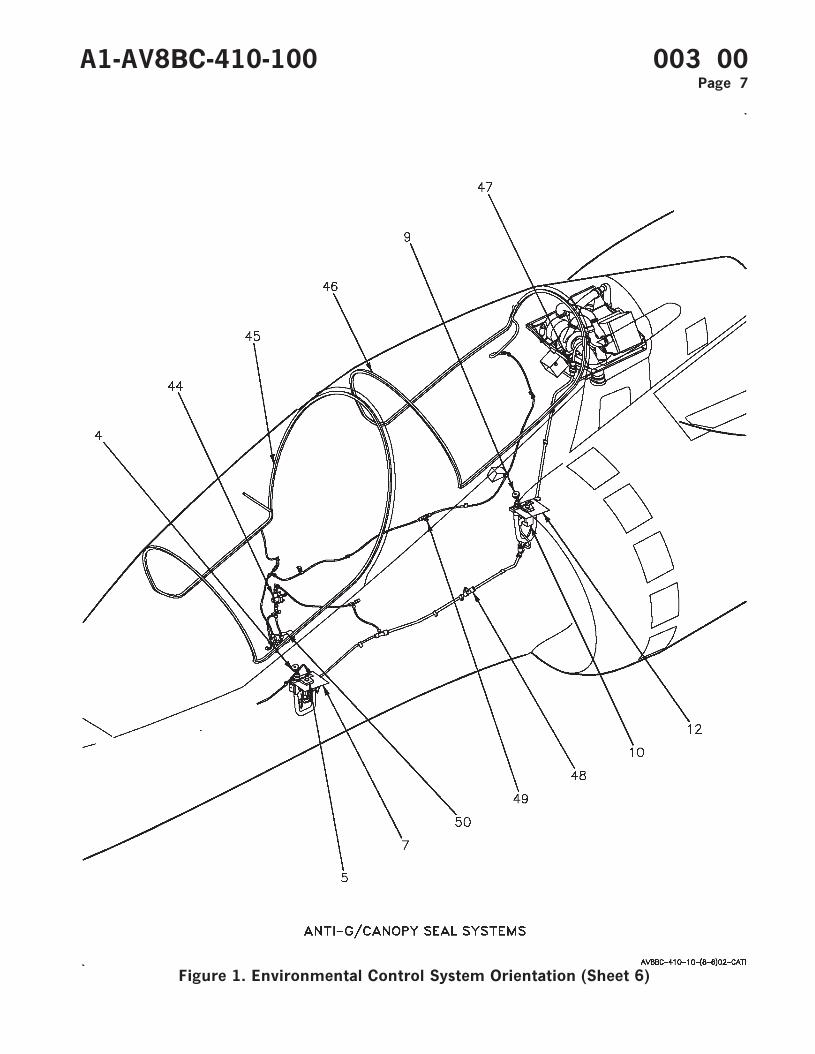
Figure 1. Environmental Control System Orientation (Sheet 6)
A1-AV8BC-410-100 003 00Page 7
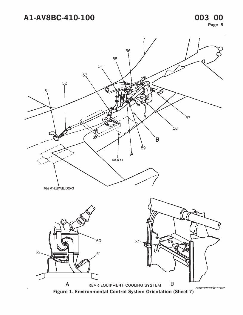
Figure 1. Environmental Control System Orientation (Sheet 7)
A1-AV8BC-410-100 003 00Page 8
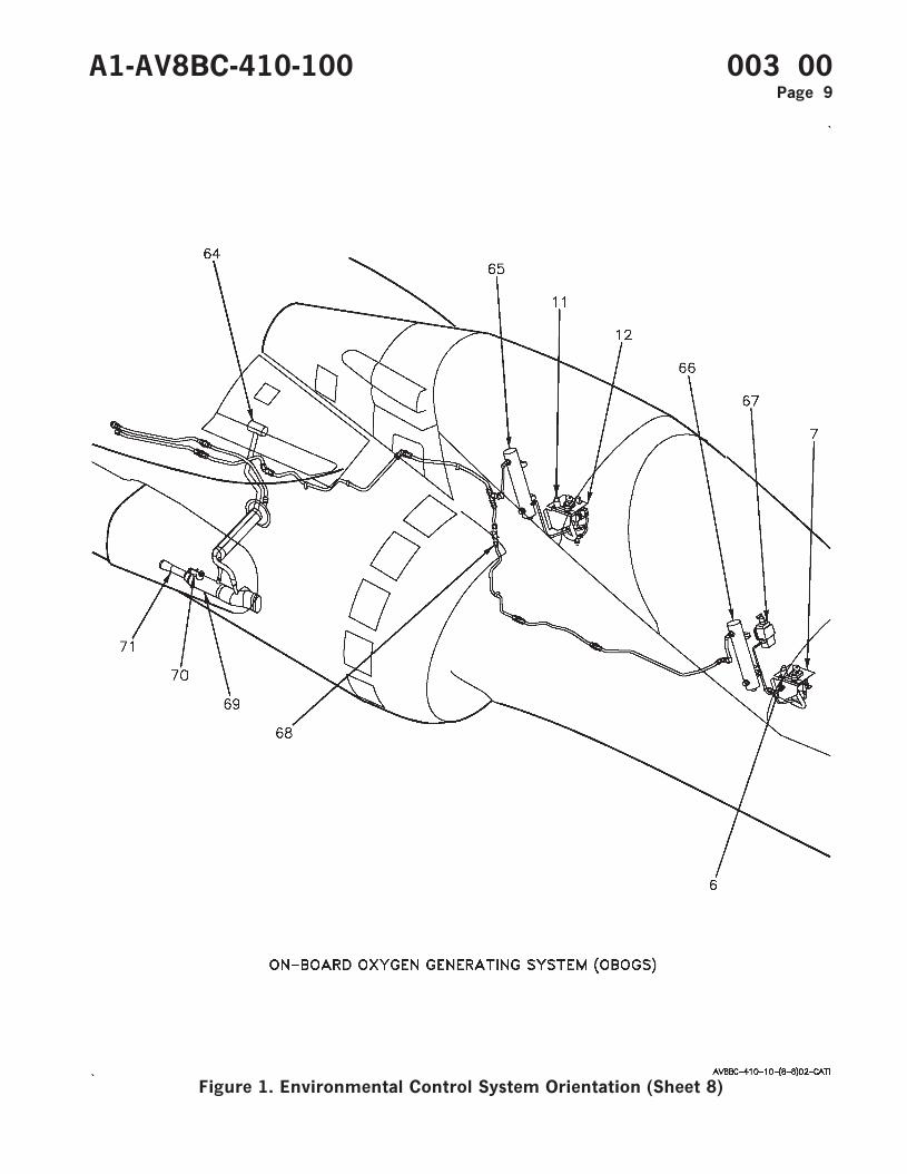
Figure 1. Environmental Control System Orientation (Sheet 8)
A1-AV8BC-410-100 003 00Page 9
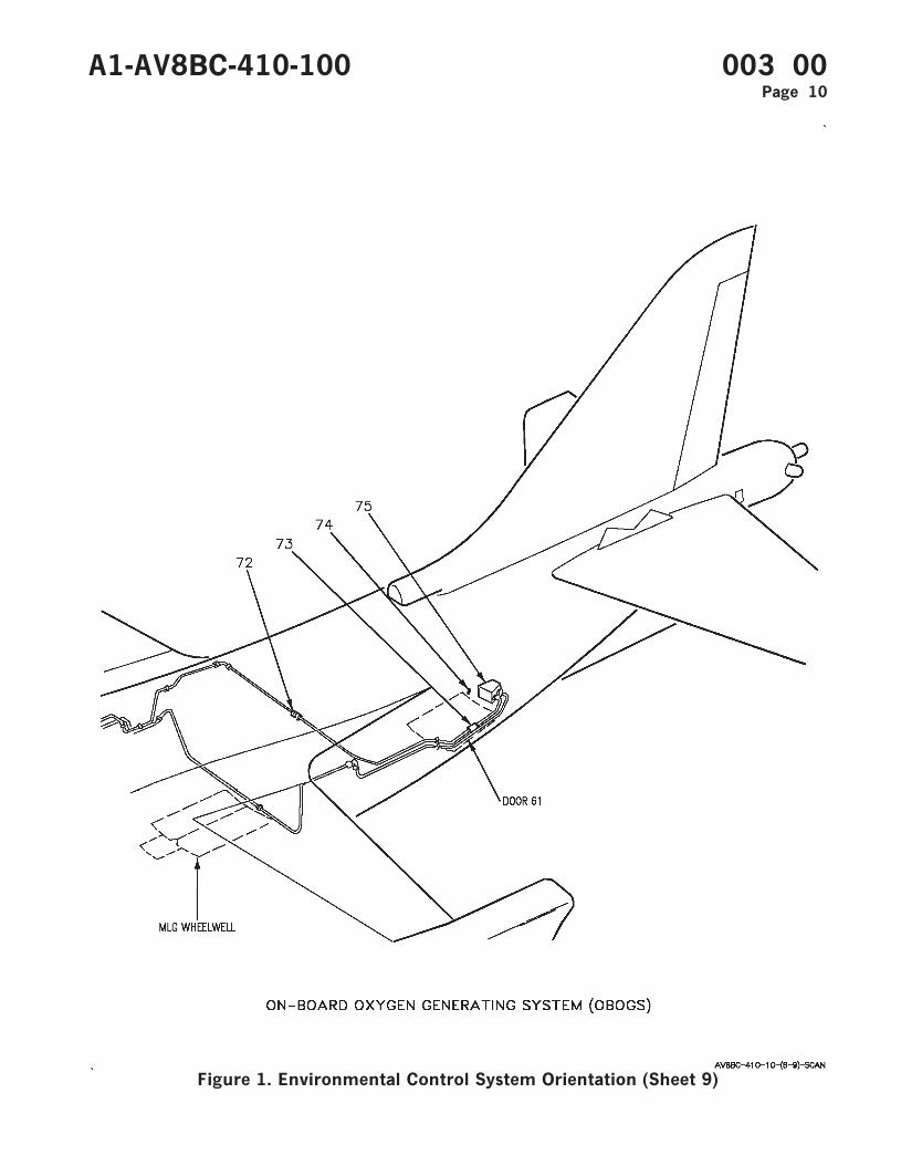
Figure 1. Environmental Control System Orientation (Sheet 9)
A1-AV8BC-410-100 003 00Page 10

INDEX
NO NOMENCLATURE
1 CAUTION/ADVISORY INDICATOR LIGHT ASSEMBLYAFT BAY CAUTION LIGHTCS COOL CAUTION LIGHTOXY CAUTION LIGHTWSHLD CAUTION LIGHT
2 PRESSURIZED COMPARTMENT ALTIMETER AAU-38/A
3 ECS CONTROL PANEL ASSEMBLYCABIN SWITCHCABIN TEMPERATURE CONTROLEQUIP SWITCHPRESS SWITCH
4 ANTI-G DISCONNECT
5 ANTI-G VALVE
6 OXYGEN DISCONNECT
7 PILOT SERVICES PANEL ASSEMBLYOXY SWITCH
8 REAR CAUTION/ADVISORY INDICATOR LIGHT ASSEMBLYAFT BAY CAUTION LIGHTCS COOL CAUTION LIGHTOXY CAUTION LIGHTWSHLD CAUTION LIGHT
9 REAR ANTI-G DISCONNECT
10 REAR ANTI-G VALVE
11 REAR OXYGEN DISCONNECT
12 REAR PILOT SERVICES PANEL ASSEMBLYOXY SHUTOFF VALVE
13 TEMPERATURE REGULATING VALVE
14 ECS PRESSURE SWITCH
15 COLD AIR UNIT
16 PRIMARY HEAT EXCHANGER
17 CABIN ECS PRESSURE REGULATING AND SHUTOFF VALVE
18 CABIN ECS AIR FILTER ASSEMBLY
A1-AV8BC-410-100 003 00Page 11
Figure 1. Environmental Control System Orientation (Sheet 10)
INDEX
NO NOMENCLATURE
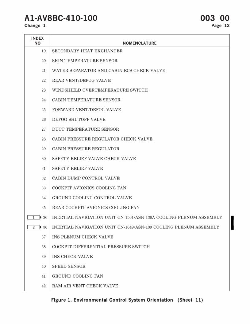
19 SECONDARY HEAT EXCHANGER
20 SKIN TEMPERATURE SENSOR
21 WATER SEPARATOR AND CABIN ECS CHECK VALVE
22 REAR VENT/DEFOG VALVE
23 WINDSHIELD OVERTEMPERATURE SWITCH
24 CABIN TEMPERATURE SENSOR
25 FORWARD VENT/DEFOG VALVE
26 DEFOG SHUTOFF VALVE
27 DUCT TEMPERATURE SENSOR
28 CABIN PRESSURE REGULATOR CHECK VALVE
29 CABIN PRESSURE REGULATOR
30 SAFETY RELIEF VALVE CHECK VALVE
31 SAFETY RELIEF VALVE
32 CABIN DUMP CONTROL VALVE
33 COCKPIT AVIONICS COOLING FAN
34 GROUND COOLING CONTROL VALVE
35 REAR COCKPIT AVIONICS COOLING FAN
Ñ1 36 INERTIAL NAVIGATION UNIT CN-1561/ASN-130A COOLING PLENUM ASSEMBLY
Ñ2 36 INERTIAL NAVIGATION UNIT CN-1649/ASN-139 COOLING PLENUM ASSEMBLY
37 INS PLENUM CHECK VALVE
38 COCKPIT DIFFERENTIAL PRESSURE SWITCH
39 INS CHECK VALVE
40 SPEED SENSOR
41 GROUND COOLING FAN
42 RAM AIR VENT CHECK VALVE
A1-AV8BC-410-100 003 00Change 1 Page 12
Figure 1. Environmental Control System Orientation (Sheet 11)

INDEX
NO NOMENCLATURE
43 GROUND COOLING VALVE
44 CANOPY SEAL PRESSURE REGULATOR AND CHECK VALVE
45 FORWARD CANOPY PRESSURE SEAL
46 AFT CANOPY PRESSURE SEAL
47 ANTI-G/CANOPY SEAL CHECK VALVE
48 CANOPY SEAL WATER DRAIN VALVE
49 ANTI-G/CANOPY SEAL TEST PORT
50 CANOPY SEAL CONTROL VALVE
51 REAR ECS AIR FILTER ASSEMBLY
52 REAR ECS PRESSURE REDUCING AND SHUTOFF VALVE
53 REAR ECS AIR INLET TEMPERATURE SWITCH
54 REAR ECS GROUND COOLING FAN
55 REAR ECS TEMPERATURE CONTROL VALVE
56 REAR ECS HEAT EXCHANGER
57 REAR ECS CHECK VALVE
58 REAR ECS COLD AIR UNIT
59 REAR ECS TEMPERATURE SENSOR
60 REAR ECS GROUND COOLING VALVE
61 REAR ECS COLD AIR UNIT PRESSURE SWITCH
62 REAR ECS GROUND COOLING FAN PRESSURE SWITCH
63 REAR ECS GROUND COOLING FAN SPEED SENSOR
64 OBOGS BLEED AIR SHUTOFF VALVE
65 REAR OXYGEN PLENUM
66 OXYGEN PLENUM
67 OXYGEN MONITOR ASSEMBLY CRU-91/A
A1-AV8BC-410-100 003 00Change 2 Page 13
Figure 1. Environmental Control System Orientation (Sheet 12)
INDEX
NO NOMENCLATURE
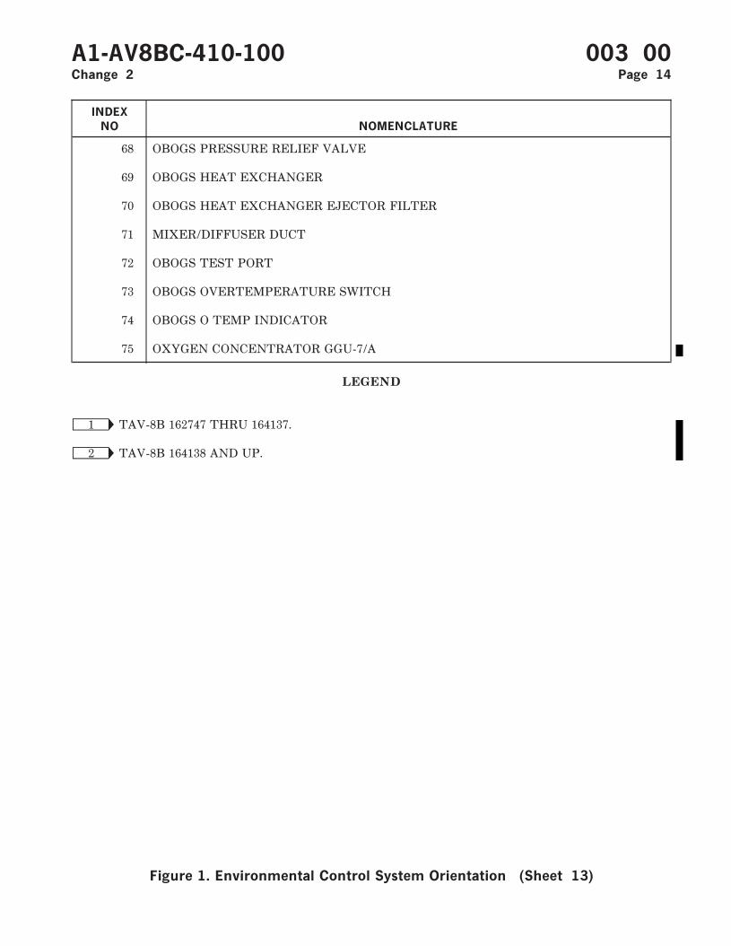
68 OBOGS PRESSURE RELIEF VALVE
69 OBOGS HEAT EXCHANGER
70 OBOGS HEAT EXCHANGER EJECTOR FILTER
71 MIXER/DIFFUSER DUCT
72 OBOGS TEST PORT
73 OBOGS OVERTEMPERATURE SWITCH
74 OBOGS O TEMP INDICATOR
75 OXYGEN CONCENTRATOR GGU-7/A
LEGEND
Ñ1 TAV-8B 162747 THRU 164137.
Ñ2 TAV-8B 164138 AND UP.
A1-AV8BC-410-100 003 00Change 2 Page 14
Figure 1. Environmental Control System Orientation (Sheet 13)
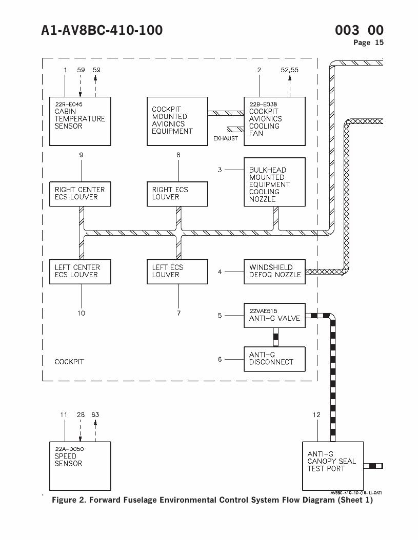
Figure 2. Forward Fuselage Environmental Control System Flow Diagram (Sheet 1)
A1-AV8BC-410-100 003 00Page 15
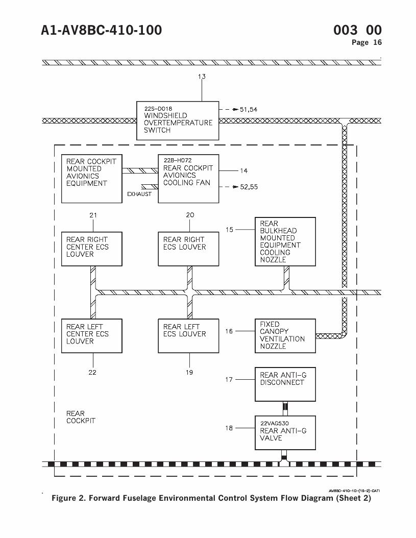
Figure 2. Forward Fuselage Environmental Control System Flow Diagram (Sheet 2)
A1-AV8BC-410-100 003 00Page 16

Figure 2. Forward Fuselage Environmental Control System Flow Diagram (Sheet 3)
A1-AV8BC-410-100 003 00Page 17
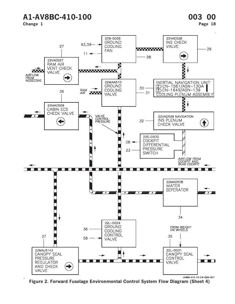
Figure 2. Forward Fuselage Environmental Control System Flow Diagram (Sheet 4)
A1-AV8BC-410-100 003 00Change 1 Page 18
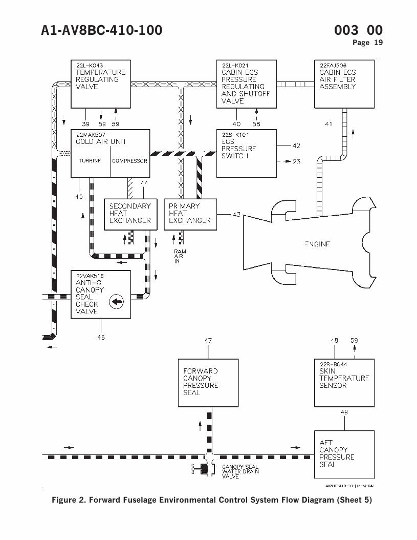
Figure 2. Forward Fuselage Environmental Control System Flow Diagram (Sheet 5)
A1-AV8BC-410-100 003 00Page 19

Figure 2. Forward Fuselage Environmental Control System Flow Diagram (Sheet 6)
A1-AV8BC-410-100 003 00Page 20

Figure 2. Forward Fuselage Environmental Control System Flow Diagram (Sheet 7)
A1-AV8BC-410-100 003 00Change 1 Page 21
ITEM
NO NOMENCLATURE
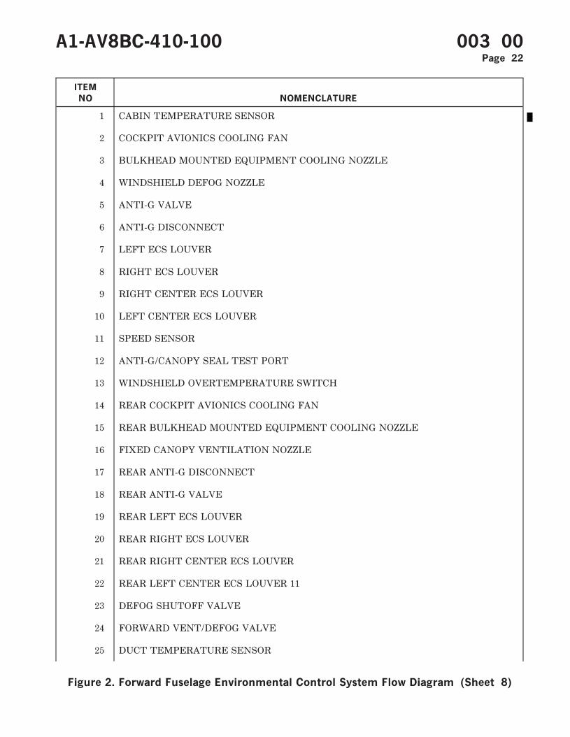
1 CABIN TEMPERATURE SENSOR
2 COCKPIT AVIONICS COOLING FAN
3 BULKHEAD MOUNTED EQUIPMENT COOLING NOZZLE
4 WINDSHIELD DEFOG NOZZLE
5 ANTI-G VALVE
6 ANTI-G DISCONNECT
7 LEFT ECS LOUVER
8 RIGHT ECS LOUVER
9 RIGHT CENTER ECS LOUVER
10 LEFT CENTER ECS LOUVER
11 SPEED SENSOR
12 ANTI-G/CANOPY SEAL TEST PORT
13 WINDSHIELD OVERTEMPERATURE SWITCH
14 REAR COCKPIT AVIONICS COOLING FAN
15 REAR BULKHEAD MOUNTED EQUIPMENT COOLING NOZZLE
16 FIXED CANOPY VENTILATION NOZZLE
17 REAR ANTI-G DISCONNECT
18 REAR ANTI-G VALVE
19 REAR LEFT ECS LOUVER
20 REAR RIGHT ECS LOUVER
21 REAR RIGHT CENTER ECS LOUVER
22 REAR LEFT CENTER ECS LOUVER 11
23 DEFOG SHUTOFF VALVE
24 FORWARD VENT/DEFOG VALVE
25 DUCT TEMPERATURE SENSOR
A1-AV8BC-410-100 003 00Page 22
Figure 2. Forward Fuselage Environmental Control System Flow Diagram (Sheet 8)

ITEM
NO NOMENCLATURE
26 REAR VENT/DEFOG VALVE
27 RAM AIR VENT CHECK VALVE
28 GROUND COOLING FAN
29 INS CHECK VALVE
Ñ2 30 INERTIAL NAVIGATION UNIT CN-1561/ASN-130A COOLING PLENUM ASSEMBLY
Ñ3 30 INERTIAL NAVIGATION UNIT CN-1649/ASN-139 COOLING PLENUM ASSEMBLY
31 GROUND COOLING VALVE
32 INS PLENUM CHECK VALVE
33 COCKPIT DIFFERENTIAL PRESSURE SWITCH
34 WATER SEPARATOR
35 CANOPY SEAL CONTROL VALVE
36 GROUND COOLING CONTROL VALVE
37 CANOPY SEAL PRESSURE REGULATOR AND CHECK VALVE
38 CABIN ECS CHECK VALVE
39 TEMPERATURE REGULATING VALVE
40 CABIN ECS PRESSURE REGULATING AND SHUTOFF VALVE
41 CABIN ECS AIR FILTER ASSEMBLY
42 ECS PRESSURE SWITCH
43 PRIMARY HEAT EXCHANGER
44 SECONDARY HEAT EXCHANGER
45 COLD AIR UNIT
46 ANTI-G/CANOPY SEAL CHECK VALVE
47 FORWARD CANOPY PRESSURE SEAL
48 SKIN TEMPERATURE SENSOR
49 AFT CANOPY PRESSURE SEAL
A1-AV8BC-410-100 003 00Change 1 Page 23
Figure 2. Forward Fuselage Environmental Control System Flow Diagram (Sheet 9)
ITEM
NO NOMENCLATURE
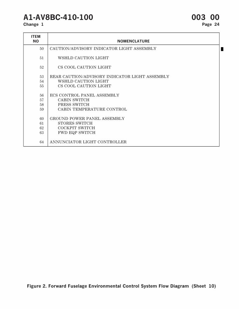
50 CAUTION/ADVISORY INDICATOR LIGHT ASSEMBLY
51 WSHLD CAUTION LIGHT
52 CS COOL CAUTION LIGHT
53 REAR CAUTION/ADVISORY INDICATOR LIGHT ASSEMBLY54 WSHLD CAUTION LIGHT55 CS COOL CAUTION LIGHT
56 ECS CONTROL PANEL ASSEMBLY57 CABIN SWITCH58 PRESS SWITCH59 CABIN TEMPERATURE CONTROL
60 GROUND POWER PANEL ASSEMBLY61 STORES SWITCH62 COCKPIT SWITCH63 FWD EQP SWITCH
64 ANNUNCIATOR LIGHT CONTROLLER
A1-AV8BC-410-100 003 00Change 1 Page 24
Figure 2. Forward Fuselage Environmental Control System Flow Diagram (Sheet 10)
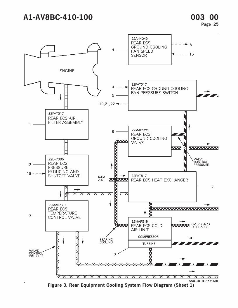
Figure 3. Rear Equipment Cooling System Flow Diagram (Sheet 1)
A1-AV8BC-410-100 003 00Page 25
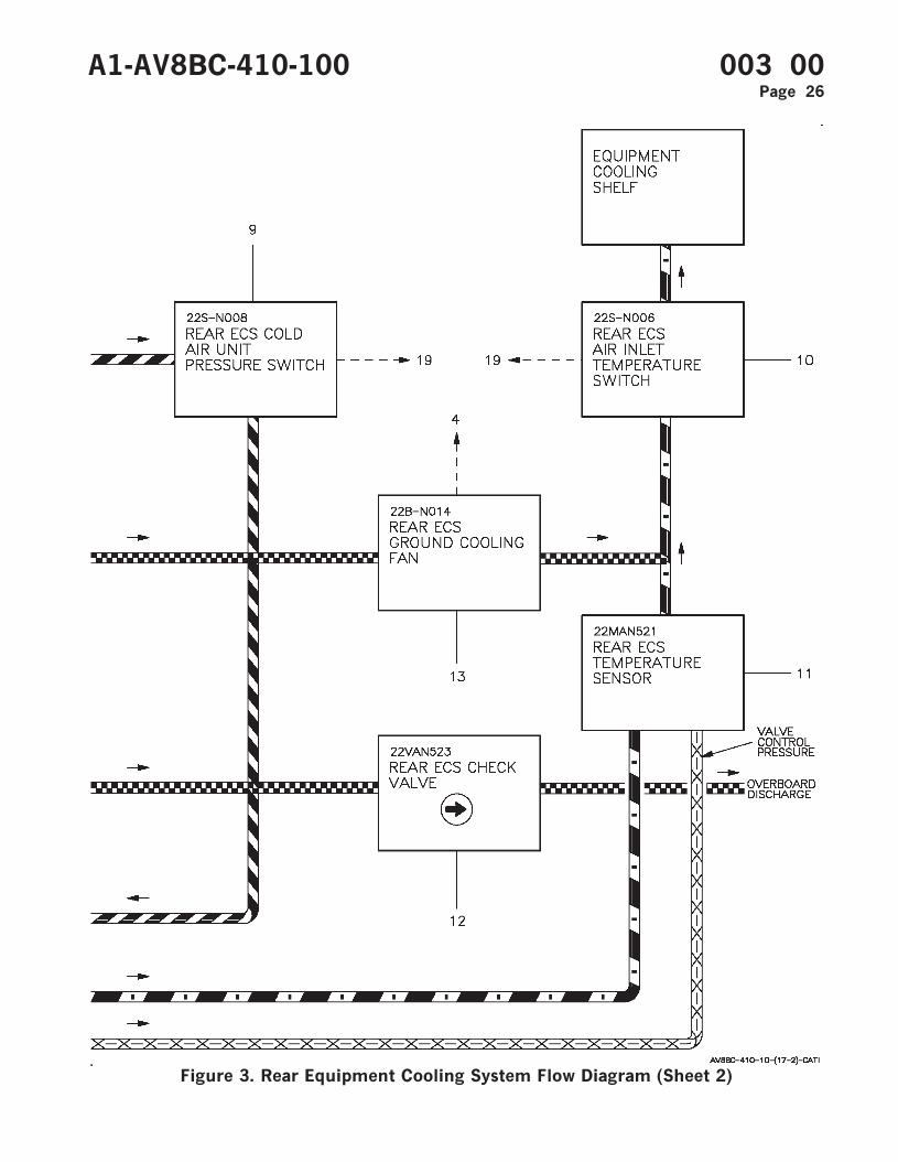
Figure 3. Rear Equipment Cooling System Flow Diagram (Sheet 2)
A1-AV8BC-410-100 003 00Page 26
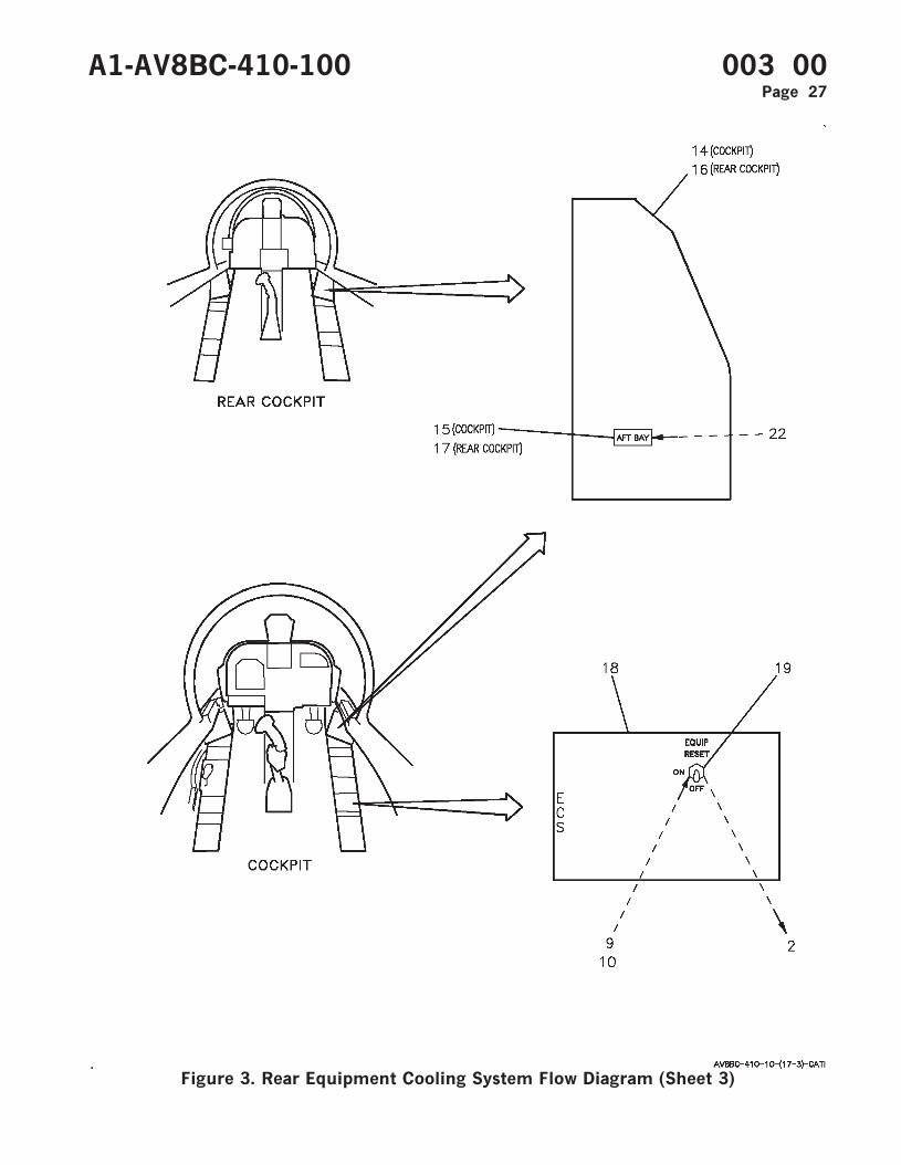
Figure 3. Rear Equipment Cooling System Flow Diagram (Sheet 3)
A1-AV8BC-410-100 003 00Page 27
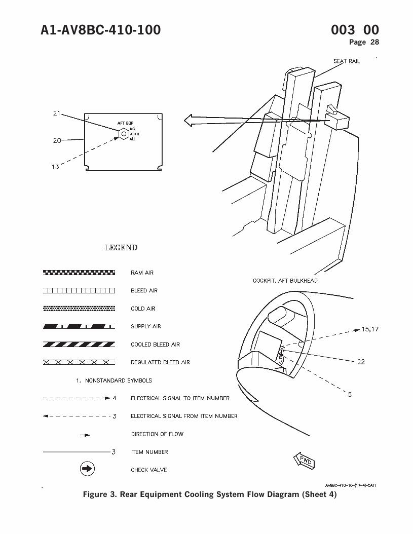
Figure 3. Rear Equipment Cooling System Flow Diagram (Sheet 4)
A1-AV8BC-410-100 003 00Page 28
ITEM
NO NOMENCLATURE
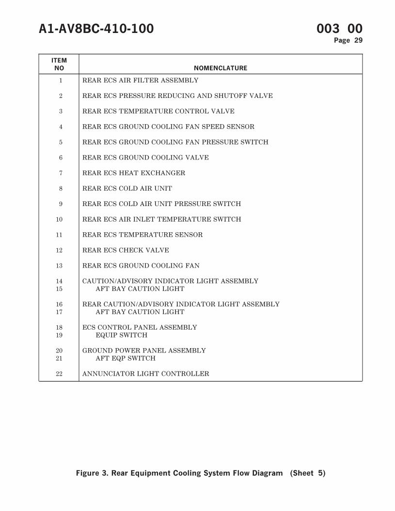
1 REAR ECS AIR FILTER ASSEMBLY
2 REAR ECS PRESSURE REDUCING AND SHUTOFF VALVE
3 REAR ECS TEMPERATURE CONTROL VALVE
4 REAR ECS GROUND COOLING FAN SPEED SENSOR
5 REAR ECS GROUND COOLING FAN PRESSURE SWITCH
6 REAR ECS GROUND COOLING VALVE
7 REAR ECS HEAT EXCHANGER
8 REAR ECS COLD AIR UNIT
9 REAR ECS COLD AIR UNIT PRESSURE SWITCH
10 REAR ECS AIR INLET TEMPERATURE SWITCH
11 REAR ECS TEMPERATURE SENSOR
12 REAR ECS CHECK VALVE
13 REAR ECS GROUND COOLING FAN
14 CAUTION/ADVISORY INDICATOR LIGHT ASSEMBLY15 AFT BAY CAUTION LIGHT
16 REAR CAUTION/ADVISORY INDICATOR LIGHT ASSEMBLY17 AFT BAY CAUTION LIGHT
18 ECS CONTROL PANEL ASSEMBLY19 EQUIP SWITCH
20 GROUND POWER PANEL ASSEMBLY21 AFT EQP SWITCH
22 ANNUNCIATOR LIGHT CONTROLLER
A1-AV8BC-410-100 003 00Page 29
Figure 3. Rear Equipment Cooling System Flow Diagram (Sheet 5)
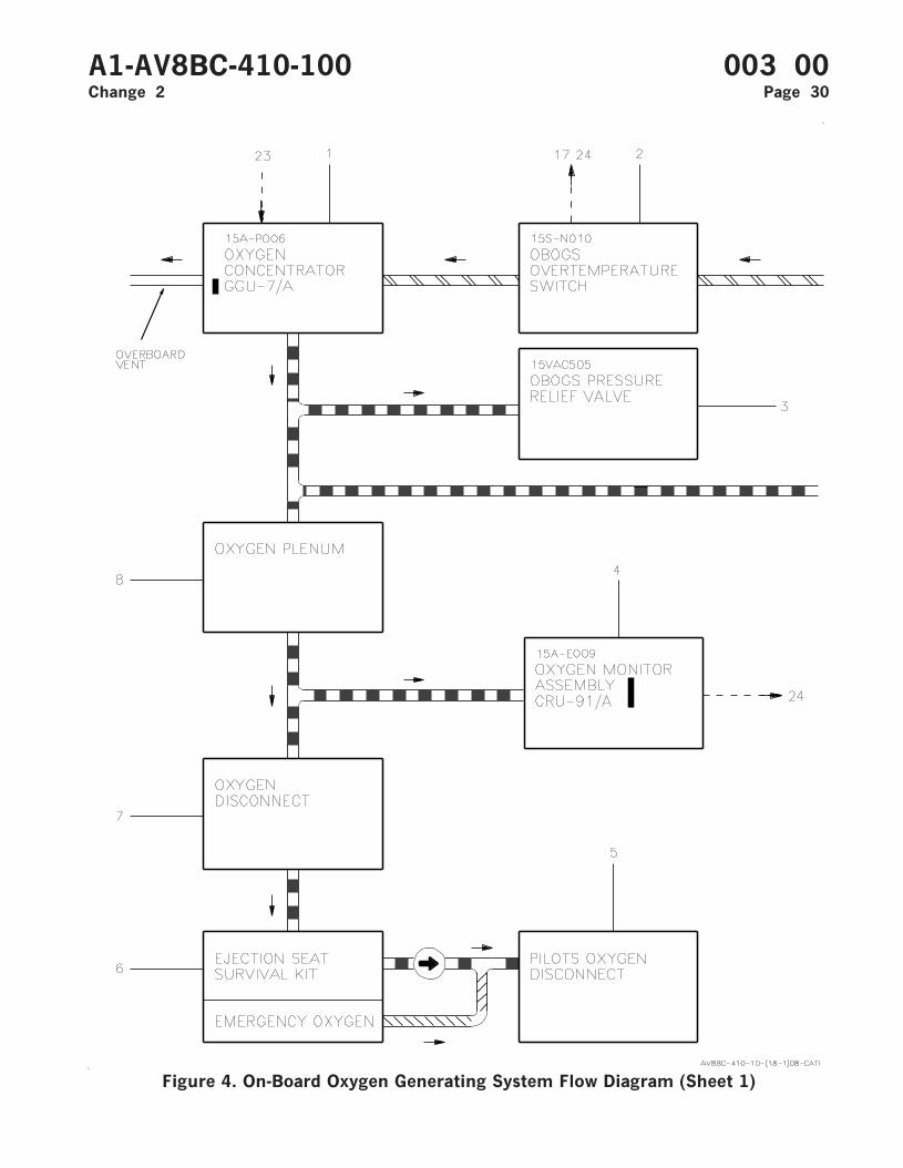
Figure 4. On-Board Oxygen Generating System Flow Diagram (Sheet 1)
A1-AV8BC-410-100 003 00Change 2 Page 30
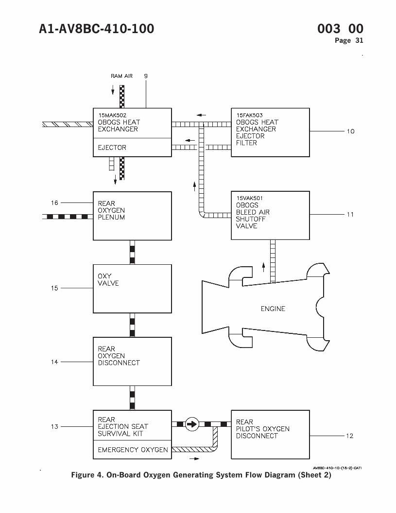
Figure 4. On-Board Oxygen Generating System Flow Diagram (Sheet 2)
A1-AV8BC-410-100 003 00Page 31
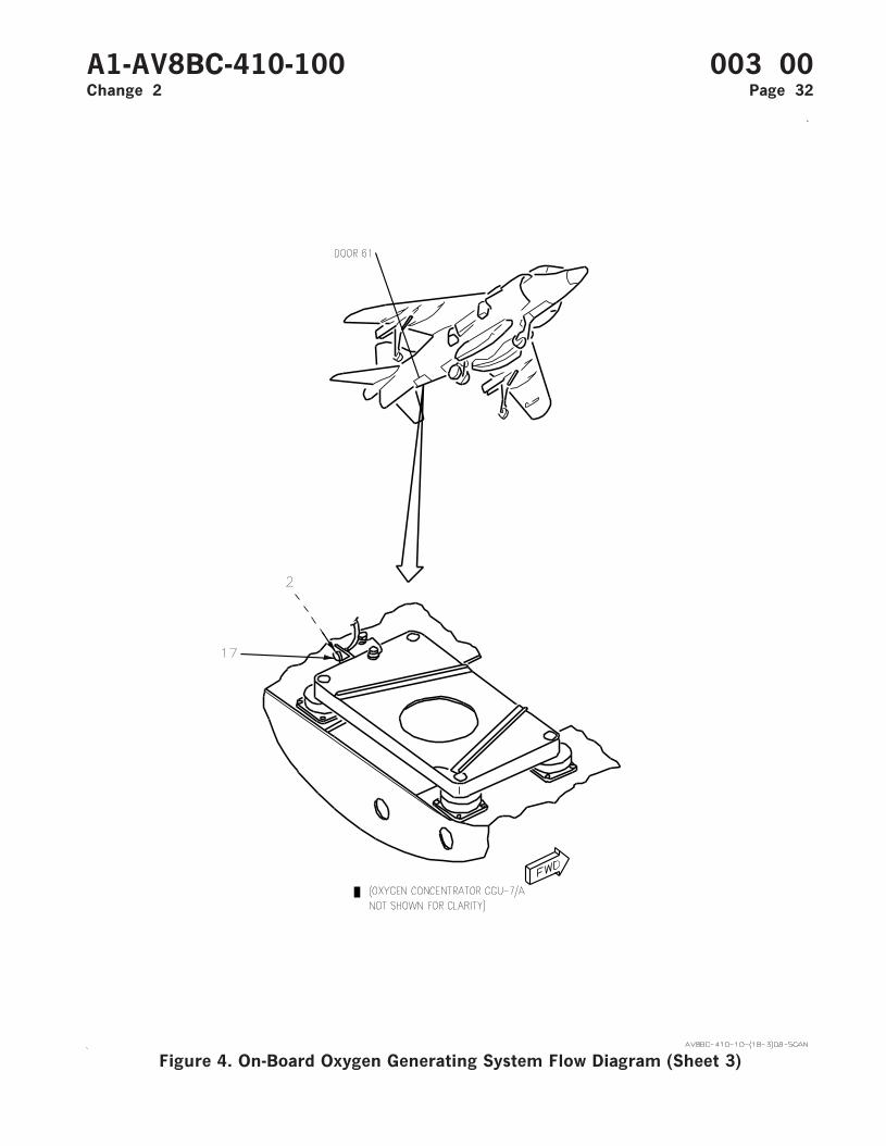
Figure 4. On-Board Oxygen Generating System Flow Diagram (Sheet 3)
A1-AV8BC-410-100 003 00Change 2 Page 32
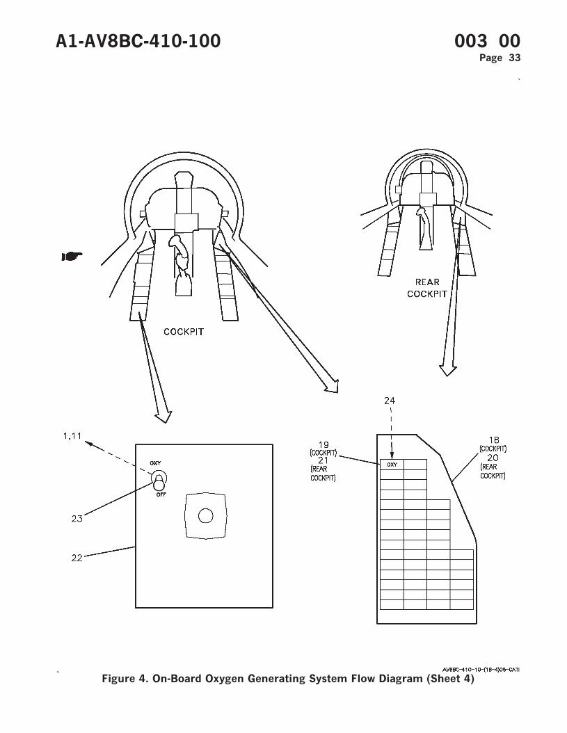
Figure 4. On-Board Oxygen Generating System Flow Diagram (Sheet 4)
A1-AV8BC-410-100 003 00Page 33

Figure 4. On-Board Oxygen Generating System Flow Diagram (Sheet 5)
A1-AV8BC-410-100 003 00Page 34
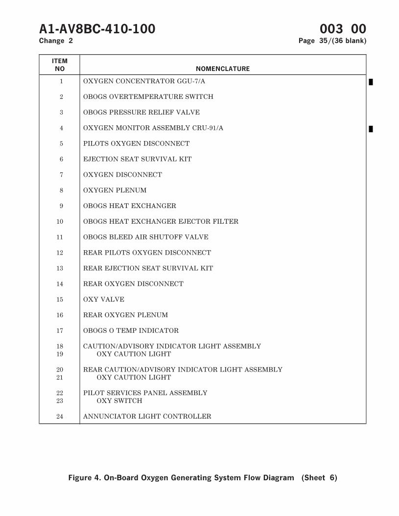
ITEM
NO NOMENCLATURE
1 OXYGEN CONCENTRATOR GGU-7/A
2 OBOGS OVERTEMPERATURE SWITCH
3 OBOGS PRESSURE RELIEF VALVE
4 OXYGEN MONITOR ASSEMBLY CRU-91/A
5 PILOTS OXYGEN DISCONNECT
6 EJECTION SEAT SURVIVAL KIT
7 OXYGEN DISCONNECT
8 OXYGEN PLENUM
9 OBOGS HEAT EXCHANGER
10 OBOGS HEAT EXCHANGER EJECTOR FILTER
11 OBOGS BLEED AIR SHUTOFF VALVE
12 REAR PILOTS OXYGEN DISCONNECT
13 REAR EJECTION SEAT SURVIVAL KIT
14 REAR OXYGEN DISCONNECT
15 OXY VALVE
16 REAR OXYGEN PLENUM
17 OBOGS O TEMP INDICATOR
18 CAUTION/ADVISORY INDICATOR LIGHT ASSEMBLY19 OXY CAUTION LIGHT
20 REAR CAUTION/ADVISORY INDICATOR LIGHT ASSEMBLY21 OXY CAUTION LIGHT
22 PILOT SERVICES PANEL ASSEMBLY23 OXY SWITCH
24 ANNUNCIATOR LIGHT CONTROLLER
A1-AV8BC-410-100 003 00Change 2 Page 35/(36 blank)
Figure 4. On-Board Oxygen Generating System Flow Diagram (Sheet 6)

ORGANIZATIONAL MAINTENANCE
PRINCIPLES OF OPERATION
DESCRIPTION AND OPERATION
CABIN COOLING AND DEFOG SYSTEM
Reference Material
Power Plant and Related Systems ................................................................................. A1-AV8BD-290-100Basic Engine .............................................................................................................. WP003 00
Environmental Control System ...................................................................................... A1-AV8BC-410-100Cabin Pressurization System................................................................................... WP006 00Component Locator - Cabin Cooling And Defog System ................................... WP005 00Forward Avionics Cooling System.......................................................................... WP008 00
Electrical Systems............................................................................................................. A1-AV8BB-420-100DC Power System ..................................................................................................... WP004 00
Electrical Systems............................................................................................................. A1-AV8BD-420-100DC Power System ..................................................................................................... WP004 00
Lighting Systems............................................................................................................... A1-AV8BB-440-100Warning/Caution/Advisory Lighting System........................................................ WP007 00
Landing Gear And Related Systems.............................................................................. A1-AV8BB-130-100Landing Gear System............................................................................................... WP003 00
Alphabetical Index
Subject Page No.
Cabin Cooling and Defog System Simplified Schematic, Figure 1...................................................... 11Description ................................................................................................................................................... 3
Component Description...................................................................................................................... 3Cabin ECS Air Filter Assembly ................................................................................................ 3Cabin ECS Check Valve............................................................................................................. 3Cabin ECS Pressure Regulating and Shutoff Valve .............................................................. 3Cabin Temperature Sensor........................................................................................................ 3Cold Air Unit ............................................................................................................................... 3Defog Shutoff Valve ................................................................................................................... 3Duct Temperature Sensor.......................................................................................................... 3ECS Control Panel Assembly.................................................................................................... 3ECS Louvers ................................................................................................................................ 3ECS Pressure Switch .................................................................................................................. 4Forward Vent/Defog Valve ........................................................................................................ 3Primary Heat Exchanger ........................................................................................................... 4Rear Vent/Defog Valve .............................................................................................................. 4
A1-AV8BC-410-100 004 00Change 7 - 15 May 2004 Page 1

Alphabetical Index (Continued)
Subject Page No.
Secondary Heat Exchanger........................................................................................................ 4Skin Temperature Sensor .......................................................................................................... 3Temperature Regulating Valve ................................................................................................. 3Venturi/Choke ............................................................................................................................. 3Water Separator .......................................................................................................................... 3Windshield Defog Nozzles/Fixed Canopy Ventilation Nozzles............................................ 3Windshield Overtemperature Switch ....................................................................................... 3
System Controls and Indicators........................................................................................................ 4CABIN Switch ............................................................................................................................. 4Cabin Temperature Control ...................................................................................................... 5Max Defog Relay......................................................................................................................... 5PRESS Switch ............................................................................................................................. 4Rear WSHLD Caution Light .................................................................................................... 5Windshield Overtemperature Relay ......................................................................................... 5WSHLD Caution Light .............................................................................................................. 5
System Description ............................................................................................................................. 3Related Systems .................................................................................................................................. 4
DC Power System ....................................................................................................................... 4Landing Gear and Related Systems......................................................................................... 4Power Plant and Related Systems ........................................................................................... 4Warning/Caution/Advisory Lighting System.......................................................................... 4
Operation...................................................................................................................................................... 6Component Operation ........................................................................................................................ 6
Cabin ECS Air Filter Assembly ................................................................................................ 6Cabin ECS Check Valve............................................................................................................. 7Cabin ECS Pressure Regulating and Shutoff Valve .............................................................. 6Cabin Temperature Sensor........................................................................................................ 9Cold Air Unit ............................................................................................................................... 7Defog Shutoff Valve ................................................................................................................... 8Duct Temperature Sensor.......................................................................................................... 9ECS Control Panel Assembly.................................................................................................... 8ECS Louvers ................................................................................................................................ 8ECS Pressure Switch .................................................................................................................. 8Fixed Canopy Ventilation Nozzles ........................................................................................... 8Forward Vent/Defog Valve ........................................................................................................ 7Primary Heat Exchanger ........................................................................................................... 6Rear Vent/Defog Valve .............................................................................................................. 7Secondary Heat Exchanger........................................................................................................ 7Skin Temperature Sensor .......................................................................................................... 8Temperature Regulating Valve ................................................................................................. 6Water Separator .......................................................................................................................... 7Windshield Defog Nozzles ......................................................................................................... 8Windshield Overtemperature Switch ....................................................................................... 8
System Operation................................................................................................................................ 9Emergency Operation ................................................................................................................. 10Normal Operation ....................................................................................................................... 9
A1-AV8BC-410-100 004 00Page 2
Record of Applicable Technical Directives
Type/
NumberDate Title and ECP or RAMEC No.
Date
Incorp.Remarks
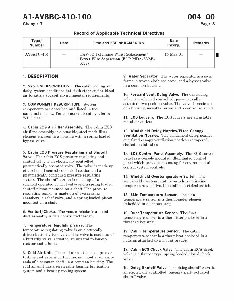
AV8AFC-416 — TAV-8B Polyimide Wire Replacement/Power Wire Separation (ECP MDA-AV8B-0277)
15 May 04 —
1. DESCRIPTION.
2. SYSTEM DESCRIPTION. The cabin cooling anddefog system conditions hot sixth stage engine bleedair to satisfy cockpit environmental requirements.
3. COMPONENT DESCRIPTION. Systemcomponents are described and listed in theparagraphs below. For component locator, refer toWP005 00.
4. Cabin ECS Air Filter Assembly. The cabin ECSair filter assembly is a reusable, steel mesh filterelement encased in a housing with a spring loadedbypass valve.
5. Cabin ECS Pressure Regulating and Shutoff
Valve. The cabin ECS pressure regulating andshutoff valve is an electrically controlled,pneumatically operated valve. The valve is made upof a solenoid controlled shutoff section and apneumatically controlled pressure regulatingsection. The shutoff section is made up of asolenoid operated control valve and a spring loadedshutoff piston mounted on a shaft. The pressureregulating section is made up of two sensingchambers, a relief valve, and a spring loaded pistonmounted on a shaft.
6. Venturi/Choke. The venturi/choke is a metalduct assembly with a constricted throat.
7. Temperature Regulating Valve. Thetemperature regulating valve is an electricallydriven butterfly type valve. The valve is made up ofa butterfly valve, actuator, an integral follow-upresistor and a brake.
8. Cold Air Unit. The cold air unit is a compressorturbine and expansion turbine, mounted at oppositeends of a common shaft, in a common housing. Thecold air unit has a serviceable bearing lubricationsystem and a bearing cooling system.
9. Water Separator. The water separator is a swirlframe, a woven cloth coalescer, and a bypass valvein a common housing.
10. Forward Vent/Defog Valve. The vent/defogvalve is a solenoid controlled, pneumaticallyactuated, two position valve. The valve is made upof a housing, movable piston and a control solenoid.
11. ECS Louvers. The ECS louvers are adjustablemetal air outlets.
12. Windshield Defog Nozzles/Fixed Canopy
Ventilation Nozzles. The windshield defog nozzlesand fixed canopy ventilation nozzles are tapered,slotted, metal tubes.
13. ECS Control Panel Assembly. The ECS controlpanel is a console mounted, illuminated controlpanel which provides mounting for environmentalcontrol system controls.
14. Windshield Overtemperature Switch. Thewindshield overtemperature switch is an in-linetemperature sensitive, bimetallic, electrical switch.
15. Skin Temperature Sensor. The skintemperature sensor is a thermometer elementimbedded in a contact strip.
16. Duct Temperature Sensor. The ducttemperature sensor is a thermistor enclosed in athreaded housing.
17. Cabin Temperature Sensor. The cabintemperature sensor is a thermistor enclosed in ahousing attached to a mount bracket.
18. Cabin ECS Check Valve. The cabin ECS checkvalve is a flapper type, spring loaded closed checkvalve.
19. Defog Shutoff Valve. The defog shutoff valve isan electrically controlled, pneumatically actuatedshutoff valve.
A1-AV8BC-410-100 004 00Change 7 Page 3
20. ECS Pressure Switch. The ECS pressure switchis a pneumatically actuated electrical switch.
21. Rear Vent/Defog Valve. The rear vent/defogvalve is a solenoid controlled, pneumaticallyactuated, two position valve. The valve is made upof a housing, movable piston, and a controlsolenoid.
22. Primary Heat Exchanger. The primary heatexchanger is a crossflow, air to air heat exchanger.The heat exchanger is made up of a finned coreenclosed in a housing.
23. Secondary Heat Exchanger. The secondaryheat exchanger is a crossflow, air to air heatexchanger. The heat exchanger is made up of afinned core enclosed in a housing.
24. RELATED SYSTEMS.
25. Power Plant and Related Systems. Hot, highpressure bleed air is provided by the engine sixthstage compressor (A1-AV8BD-290-100, WP003 00).
26. Warning/Caution/Advisory Lighting System.
The warning/caution/advisory lighting system(A1-AV8BB-440-100, WP007 00) provides visualindication of normal aircraft functions and systemmalfunctions affecting safety of flight operations.The warning/caution/advisory lighting systemincludes the annunciator light controller and thecaution/advisory indicator light assembly. Theannunciator light controller receives data fromvarious aircraft systems and provides logic to turnon and off warning/caution/advisory lights.
27. The annunciator light controller will turn onthe WSHLD caution lights and the MASTERCAUTION lights when defog air temperatureexceeds 250°F.
28. DC Power System. The DC power system on162747; ALSO 162963 THRU 163861 BEFOREAV8AFC-416 (A1-AV8BB-420-100, WP004 00) or164113 AND UP; ALSO 162963 THRU 163861AFTER AV8AFC-416 (A1-AV8BD-420-100, WP00400) provides 28vdc essential and 28vdc emergencypower for the cabin cooling and defog system.
29. Landing Gear And Related Systems. Thelanding gear system (A1-AV8BB-130-100,WP003 00) provides a weight on wheels signal forthe cabin cooling and defog system through the
MLG weight on wheels (WOW) switch and theweight on wheels relay no. 1.
30. SYSTEM CONTROLS AND INDICATORS.
31. CABIN Switch. The CABIN switch, located onthe ECS control panel assembly, is a single poletoggle switch. The switch controls airflow for cabinand windshield defogging. The switch has threepositions: NORM, DFOG, and MAX DFOG.
32. Setting the CABIN switch to NORM does thebelow:
a. Applies essential 28vdc to energize theforward vent/defog valve and rear vent/defog valve,causing them to go to the unrestricted position.
b. Applies essential 28vdc through the weighton wheels relay no. 1 to the defog shutoff valve. Thedefog valve will close if the aircraft is weight onwheels and system pressure is less than 20 psi.
33. Setting the CABIN switch to DFOG does thebelow:
a. Removes essential 28vdc to deenergize theforward vent/defog valve and rear vent/defog valve,causing them to go to the restricted position.
b. Removes essential 28vdc to open the defogshutoff valve.
34. Setting the CABIN switch to MAX DFOGapplies essential 28vdc power to energize the maxdefog relay causing an increase in system airtemperature.
35. PRESS Switch. The PRESS switch, located onthe ECS control panel assembly, is a four pole, leverlock toggle switch. The switch provides on/offcontrol for the cabin cooling and defog system andmode selection for the cabin pressurization system.Refer to WP006 00 for operation of the cabinpressurization system. The switch has threepositions; NORM, DUMP, and RAM.
36. Setting the PRESS switch to NORM prevents28vdc essential or 28vdc emergency power fromenergizing the cabin ECS pressure regulating andshutoff valve, allowing normal system operation.
37. Setting the PRESS switch to RAM applies28vdc essential and 28vdc emergency power toenergize the cabin ECS pressure regulating andshutoff valve. The valve closes when energized,stopping system operation.
A1-AV8BC-410-100 004 00Change 7 Page 4
38. Setting the PRESS switch to DUMP has noaffect on system operation.
39. Cabin Temperature Control. The cabintemperature control, located on the ECS controlpanel assembly, controls manual (MAN) andautomatic (AUTO) cabin temperature selection.
40. In the MAN mode, setting and holding thecabin temperature control knob to the COOL orWARM settings applies emergency 28vdc powerthrough the deenergized windshield overtemp relayto the open (warm) or closed (cool) contacts of thetemperature regulating valve. Voltage is applied tothe valve as long as the knob is held in COOL orWARM setting.
41. In the AUTO mode, the cabin temperaturecontrol functions as an electronic processor and asone leg of a temperature control bridge circuit. Theother legs of the bridge circuit include the cabintemperature sensor, duct temperature sensor, andskin temperature sensor and follow-up resistor.
42. Selecting the desired setting in the AUTO modeapplies emergency 28vdc power to the processingelectronics and to the normally open contacts of theheat and cool relays, and provides a resistance valuefor one leg of the bridge. The cabin temperaturecontrol continuously receives signals from all legs ofthe bridge circuit. The bridge circuit compares theselected resistance of the AUTO setting with thesensed resistance of the other bridge circuit legs.Any difference in the signals is an unbalance. Theunbalance is electronically processed and used toenergize either the heat or cool relay. Energizing therelays applies emergency 28vdc power to the open(warm) or closed (cool) contacts of the temperatureregulating valve. The valve moves as required,adding or removing hot air. Out of balance signalsare proportional to sensed temperature changes.The resistance of the sensors and follow-up resistorchanges as the valve opens and closes until abalance in the bridge circuit is arrived at.
43. An unbalance will occur by changing theselected temperature or by any change intemperature as sensed by any leg of the bridge.Such changes may be a drastic change in ambienttemperature because of increased or decreasedaltitude. The cabin temperature control willautomatically compensate for these changes tomaintain the selected temperature.
44. WSHLD Caution Light. The WSHLD cautionlight, located on the caution/advisory indicator lightassembly, is a dual lamp, indicator light.
45. The WSHLD caution light is controlled by thewindshield overtemperature switch through thewindshield overtemp relay and thewarning/caution/advisory lighting system.
46. Rear WSHLD Caution Light. The rear WSHLDcaution light, located on the rear caution/advisoryindicator light assembly, is a dual lamp indicatorlight.
47. The rear WSHLD caution light is functionallyidentical to the WSHLD caution light.
48. Windshield Overtemperature Relay. Thewindshield overtemperature relay, located on theforward relay no. 1 panel assembly, is a dual pole,double throw, 5 amperes, permanent magnet drive,armature relay.
49. The relay is energized when the windshieldovertemperature switch senses defog airtemperature is more than 250° ±8°F. With the relayenergized:
a. Emergency 28vdc is removed from the cabintemperature control and is applied directly to theclose (cool) contacts of the temperature regulatingvalve, causing a decrease in system temperature.
b. A ground is removed to enable the WSHLDcaution light and the rear WSHLD caution light.
50. With the relay deenergized:
a. Emergency 28vdc is applied to the cabintemperature control allowing removal systemoperation.
b. A ground is provided to disable the WSHLDcaution light and rear WSHLD caution light.
51. Max Defog Relay. The max defog relay, locatedon the forward relay no. 1 panel assembly, is a dualpole, double throw, 5 amperes, permanent magnetdrive, armature relay.
52. The relay is energized when the CABIN switchis set to MAX DFOG. The relay allows windshielddefogging air temperature to increase in the MAXDFOG setting. With the relay energized, signalsfrom the cabin temperature sensor and duct
A1-AV8BC-410-100 004 00Page 5
temperature sensor are routed through three fixedvalve resistors. The three resistors increase the totalsignal resistance, causing an imbalance in thetemperature control bridge circuit. The cabintemperature control will increase air temperatureuntil the bridge circuit is brought back into balance.
53. With the relay deenergized, cabin temperaturesensor and duct temperature sensor signals arerouted directly through the cabin temperaturecontrol bridge circuit.
54. OPERATION.
55. COMPONENT OPERATION.
56. Cabin ECS Air Filter Assembly. The cabinECS air filter assembly is located in door 11L. Sixthstage engine bleed air is sent by way of ducting tothe filter assembly. The filter assembly removesparticulate contamination before it can causedamage further downstream in the environmentalcontrol systems. If the filter element becomesblocked, pressure build up opens a bypass valveallowing air to bypass the filter element. The bypassvalve opens at 4 psid. The filter element isreplaceable independent of the housing or may becleaned and reused. With the filter elementremoved, a ground air source can be adapted andused for ground testing.
57. Cabin ECS Pressure Regulating and Shutoff
Valve. The cabin pressure regulating and shutoffvalve is located in the bleed air duct between thecabin ECS air filter assembly and primary heatexchanger in door 128. Operation of the pressureregulating section and shutoff section is separate.Both sections require engine bleed air for operation.
58. The shutoff section is controlled by the PRESSswitch on the ECS control panel assembly. With thesolenoid deenergized, bleed air is applied to theupstream side of the shutoff piston, moving it to theopen position. With the solenoid energized thecontrol valve opens equalizing bleed air pressure onboth sides of the shutoff piston which closes byspring tension. In the event of an aircraft or valveelectrical failure, the valve will fail to the openposition. The shutoff section will be inoperative, butthe pressure regulation section will continue tooperate.
59. The pressure regulating section operates onlywith the shutoff section open. Bleed air pressureenters both sensing chambers. Pressure in one
chamber is held constant by the relief valve.Differences of pressure between the two chambersdetermines piston position, controlling air pressurepassing into the system. Pressure is regulated toapproximately 62 psi.
60. Temperature Regulating Valve. Thetemperature regulating valve is located in door 128between the cabin pressure regulator and shutoffvalve and the water separator. The valve iselectrically controlled and electrically actuated.
61. Acting in response to electrical signals from thecabin temperature control, the valve moves open orclosed. Opening the valve allows more hot air to mixwith cold discharge air from the cold air unit.Closing the valve allows less hot air mixing. Cycletime of the valve from fully open to fully closed isapproximately 15 seconds.
The valve motor has limit switches and a brake toprevent overtravel of the valve. The closed limitswitch is open when the valve is closed. The limitswitch opens the circuit for the valve anddeenergizes the brake coil. Power to the motor isinterrupted and the brake engages. As the valveopens, the closed limit switch closes. When thevalve is fully open, the process repeats for the openlimit switch.
62. The follow-up resistor is a variable resistormechanically controlled by position of the valveactuator. Resistance values increase as the valvemoves to open, decrease as the valve moves toclosed. The resistance value range is approximately0 to 33 ohms. The resistance value is supplied tothe automatic mode of the cabin temperaturecontrol as part of one leg of the bridge circuit.
63. Primary Heat Exchanger. The primary heatexchanger is located in door 128 between the cabinECS pressure regulating and shutoff valve and thecold air unit. Hot bleed air passes through the heatexchanger core where ram air, forced across thecore, absorbs heat from the bleed air. The bleed airpasses through the heat exchanger then to the coldair unit compressor turbine. The pre-cooled,compressed bleed air is then sent to the secondaryheat exchanger.
64. After passing across the primary heatexchanger, the ram air exits through either the ECSbay or the engine intake, depending on flightconditions. In low speed flight or ground operation,flapper valves at the bottom of the heat exchanger
A1-AV8BC-410-100 004 00Page 6
are pulled open by suction in the engine air intake,allowing engine intake suction to pull ram air acrossthe heat exchanger core. In normal flight, ram airflow causes a positive pressure in the ram air ducts,pulling the flapper valves closed. The ram air thenexits to the ECS bay and then overboard.
65. Secondary Heat Exchanger. The secondaryheat exchanger is located in door 128 between thecold air unit compressor turbine outlet andexpansion turbine inlet. Pre-cooled, compressedbleed air from the cold air unit compressor turbinepasses through the heat exchanger core where ramair, forced across the core, absorbs heat gainedthrough compression. The cooled air then passes tothe expansion turbine inlet of the cold air unit.
66. The exit path of the ram air is the same as theprimary heat exchanger.
67. Cold Air Unit. The cold air unit is located indoor 128 between the heat exchangers and thewater separator. The compressor turbine receivespre-cooled air from the primary heat exchangerwhere it is compressed to approximately two timesits inlet value. The compressed air then passes tothe secondary heat exchanger where the heat fromcompression is lost, then to the expansion turbineend of the cold air unit where heat energy isconverted to mechanical energy by spinning theexpansion turbine. The expansion turbine drives thecompressor turbine through the common shaft.With the heat lost, cold air is left and sent by wayof ducting to mix with hot air from the temperatureregulating valve.
68. Lubrication for the common shaft is providedby oil stored in a cotton wool pack sump andtransported to the shaft by a system of oil wicks.The sump has fill and drain plugs located to allowperiodic servicing of oil while the cold air unit isstill in the aircraft.
69. Shaft bearing cooling is provided by a flexibletube. Expansion turbine discharge air is used tocool the bearings as the common shaft spins.
70. Water Separator. The water separator islocated between the cold air unit and the cabin ECScheck valve in internal door NWA. Cool moist airenters the water separator coalescer. The coalescerconverts moisture in the air into water dropletsthrough the wettable, high surface area of thewoven cloth coalescer. The swirl frame sends thesedroplets to the outer wall of the collector sump area
by centrifugal force. The droplets are collected bythe sump assembly and allowed to drain overboard.
71. If the coalescer becomes blocked, normallybecause of freezing, a bypass valve will open at a 10psi differential pressure.
72. Cabin ECS Check Valve. The cabin ECS checkvalve is located between the water separator andthe duct temperature sensor in internal door NWA.The valve prevents cabin depressurization bystopping the reverse flow of cabin air, through ECSlouvers, windshield defog nozzles, and fixed canopyventilation nozzles when cabin cooling and defogsystem is not operating. The valve flappers are heldclosed by spring tension and are normally closedwith no air pressure applied. Approximately 4 psi isrequired to open the check valve.
73. Forward Vent/Defog Valve. The forwardvent/defog valve, located between the waterseparator and the cockpit ECS louvers in door 10,provides restricted or unrestricted flow. The valvesolenoid is energized when the CABIN switch is setto NORM and deenergized when the CABIN switchis set to DFOG or MAX DFOG. With the solenoidenergized, pneumatic pressure is turned off,allowing system pressure to force the movablepiston to the unrestricted position. With the valvein the unrestricted position, most of the airflow willbe directed to the cockpit ECS louvers.
74. Deenergizing the solenoid applies pneumaticpressure to the movable piston, causing it to moveto the restricted position; most of the airflow willthen be directed to the windshield defog nozzlesand the fixed canopy ventilation nozzles.
75. Rear Vent/Defog Valve. The rear vent/defogvalve, located between the duct temperature sensorand the rear cockpit ECS louvers in door 121,provides restricted or unrestricted flow. The valvesolenoid is energized when the CABIN switch is setto NORM and deenergized with the CABIN switchset to DFOG or MAX DFOG. With the solenoidenergized, pneumatic pressure is turned off allowingsystem pressure to force the movable piston to theunrestricted position. With the valve in theunrestricted position, most of the airflow will bedirected to the rear cockpit ECS louvers.
76. Deenergizing the solenoid applies pneumaticpressure to the movable piston, causing it to moveto the restricted position; most of the airflow will
A1-AV8BC-410-100 004 00Page 7
then be directed to the fixed canopy ventilationnozzles and windshield defog nozzles.
77. ECS Louvers. The ECS louvers, located in thecockpit and rear cockpit, provide desireddistribution of air entering the cockpits. Each of thelouvers has adjustable vanes at the openings. Thevanes can be adjusted by the pilot for his ownheating and cooling comfort. Airflow to the ECSlouvers is controlled by the forward vent/defogvalve and the rear vent/defog valve. The louversalso act as an air inlet for cabin pressurization(WP006 00).
78. Windshield Defog Nozzles. The windshielddefog nozzles, at the base of the windshield, provideeven flow of air across the windshield and canopy.Cabin air is used for windshield and canopydefogging. Air flow to the nozzles is controlled bythe forward vent/defog valve, rear vent/defog valve,and defog shutoff valve. The nozzles also act as anair inlet for cabin pressurization (WP006 00).
79. Fixed Canopy Ventilation Nozzles. The fixedcanopy ventilation nozzles at the base of the fixedcanopy provide an even flow of air across the fixedcanopy. Cabin air is used for fixed canopydefogging. The nozzles also provide thoroughventilation in and around the rear cockpit. Airflowto the nozzles is controlled by the forwardvent/defog valve, rear vent/defog valve and defogshutoff valve. The nozzles also act as an air inlet forcabin pressurization (WP006 00).
80. Defog Shutoff Valve. The defog shutoff valve islocated in the common windshield defog and fixedcanopy ventilation duct in door 121. The valvecontrols the flow of air to the windshield defognozzles and fixed canopy ventilation nozzles whenthe aircraft is on the ground and system pressure islow. The valve is electrically controlled andpneumatically actuated. The valve is controlled bythe weight on wheels relay no. 1 and the ECSpressure switch.
81. With aircraft weight on wheels and systempressure less than 20 psi, the defog shutoff valve isclosed. The valve is energized and pneumaticpressure is allowed to pass. The pressure, acting ona diaphragm, overcomes spring tension to close thevalve butterfly by way of a mechanical linkage.With aircraft weight off wheels or system pressuregreater than 20 psi, the defog shutoff valve is open.The valve is deenergized and pneumatic pressure is
shut off. Spring tension overcomes pneumaticpressure to open the valve.
82. ECS Pressure Switch. The ECS pressure switchis located in door 128 in the primary heat exchangeroutlet. The switch is pneumatically operated andcontrols electrical signals to the defog shutoff valve.
83. With system pressure less than 20 psi, a groundis supplied to energize the defog shutoff valve. Withsystem pressure greater than 20 psi, the pneumaticswitch opens to remove the ground signal, todeenergize the defog shutoff valve.
84. ECS Control Panel Assembly. The ECS controlpanel assembly is located in the cockpit on the rightconsole. The panel provides mounting for thePRESS switch, CABIN switch, cabin temperaturecontrol, and EQUIP switch (WP008 00).
85. Windshield Overtemperature Switch. Thewindshield overtemperature switch is located indoor 120 in the defog shutoff valve outlet duct. Abimetallic temperature sensitive device senses anovertemperature condition. The bimetallicproperties allow the device to expand and contractto actuate the switch.
86. The switch is calibrated to close its contacts at250 ±8°F increasing temperature and open at 220±10°F decreasing temperature.
87. Closing the switch contacts provides a ground tocomplete a circuit which applies emergency 28vdcpower to energize the windshield overtemperaturerelay.
88. Skin Temperature Sensor. The skintemperature sensor is located on the left side noselanding gear wheelwell. The sensor senses changesin aircraft skin temperature. The sensing devicecontact strip is attached directly to the aircraftskin. A dielectric compound is used between thesensor and the aircraft skin to make sure the sensoris electrically isolated from the skin, but still able tomeasure temperature.
89. As sensed temperature increases, sensorresistance increases. As sensed temperaturedecreases, sensor resistance decreases. At atemperature range of 0 to 100°F (−17 to 40°C),sensor resistance is approximately 38 to 57 ohms.The resistance values are supplied to the automaticmode of the cabin temperature control as part ofone leg of the bridge circuit.
A1-AV8BC-410-100 004 00Page 8
90. Duct Temperature Sensor. The ducttemperature sensor is located in a duct between thewater separator and the vent/defog valves in door121. The sensor senses changes of air temperaturein the cabin ECS duct.
91. As sensed temperature increases, sensorresistance decreases. As sensed temperaturedecreases, sensor resistance increases. At atemperature range of 32 to 100°F (0 to 40°C),sensor resistance is approximately 1075 to 4850ohms. The resistance values are supplied to theautomatic mode of the cabin temperature control asone leg of the bridge circuit.
92. Cabin Temperature Sensor. The cabintemperature sensor is located on the forwardpressure bulkhead, in door 7L. The sensor senseschanges in cabin air temperature.
93. As sensed temperature increases, sensorresistance decreases. As sensed temperaturedecreases, sensor resistance increases. At atemperature range of 32 to 100°F (0 to 40°C),sensor resistance is approximately 1075 to 5000ohms. The resistance values are supplied to theautomatic mode of the cabin temperature control asone leg of the bridge circuit.
94. SYSTEM OPERATION.
95. Normal Operation. In normal operation, hotengine bleed air passes through the cabin ECS airfilter (figure 1) to the cabin ECS pressure regulatingand shutoff valve which regulates pressure toapproximately 62 psi. The regulated air passesthrough the venturi/choke where airflow is limitedto approximately 36 pounds per minute. Regulatedair then passes into two circuits, one remains hot,the other passes to the primary heat exchanger tobe cooled. Hot air entering the primary heatexchanger is cooled by cross flowing ram air. Partlycooled air is then transported by way of ducting tothe compressor turbine of the cold air unit where itis compressed to approximately two times its inletvalue. Heat gained from the cold air unitcompressor turbine is lost in the secondary heatexchanger. Air from the secondary heat exchanger iscooled further by rapid expansion in the cold airunit expansion turbine section.
96. The temperature regulating valve controls theamount of hot bleed air to be mixed with cold airunit discharge air. Hot and cold air are mixed to therequired temperature.
97. Distribution of air in the cockpits is determinedby the forward vent/defog valve and the rearvent/defog valve through the ECS louvers. WithCABIN switch set to NORM, most of the airflowwill pass unrestricted to the ECS louvers. With theCABIN switch set to DFOG or MAX DFOG, mostof the airflow will be directed to the windshielddefog nozzles and fixed canopy ventilation nozzles.
98. With weight on wheels and system pressure lessthan 20 psi, the defog shutoff valve is closed todirect all airflow to the crewmembers through theECS louvers. With weight off wheels and systempressure greater than 20 psi, the defog shutoff valveopens to allow a more balanced airflow betweennozzles and louvers.
99. Cabin temperature can be controlledautomatically or manually. In automatic operation,the cabin temperature control working with thecabin temperature sensor, duct temperature sensor,and skin temperature sensor and follow-up resistorautomatically adjust temperature regulating valveposition to control the temperature of air enteringthe cabin.
100. With the cabin temperature control set toMAN WARM or MAN COOL, 28vdc is applied tothe temperature regulating valve to control thetemperature of the air entering the cabin.
101. Air for canopy and windshield defogging andfixed canopy ventilation is provided through thewindshield defog nozzles and fixed canopyventilation nozzles. Setting the CABIN switch toDFOG will direct most of the airflow to thewindshield defog nozzles. With CABIN switch set toMAX DFOG, the max defog relay is energized,causing the temperature of the airflow to increase.The windshield overtemperature switch limitswindshield defog air temperature to approximately250°F. If an overtemperature condition exists, theswitch provides a ground to energize the windshieldovertemperature relay. With the relay energized, thetemperature regulating valve will close and theWSHLD caution lights are enabled.
A1-AV8BC-410-100 004 00Page 9
102. EMERGENCY OPERATION. If the cabincooling and defog system fails or is off, ram air canbe used to ventilate the cockpit. Setting the PRESSswitch to RAM closes the cabin ECS pressureregulating and shutoff valve. Control air pressure to
the ground cooling valve is shut off, causing thevalve to open (WP008 00). With the ground coolingvalve open, ram air can enter the cockpits throughthe ECS louvers, windshield defog nozzles and fixedcanopy ventilation nozzles.
A1-AV8BC-410-100 004 00Page 10
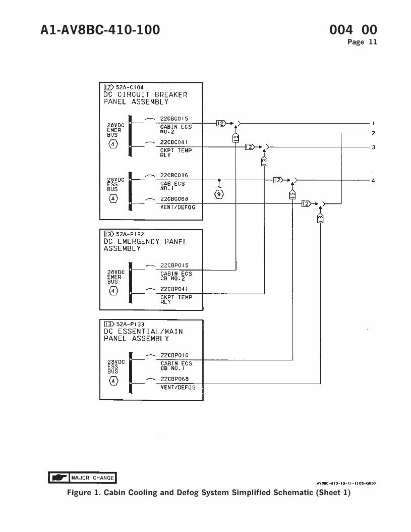
Figure 1. Cabin Cooling and Defog System Simplified Schematic (Sheet 1)
A1-AV8BC-410-100 004 00Page 11
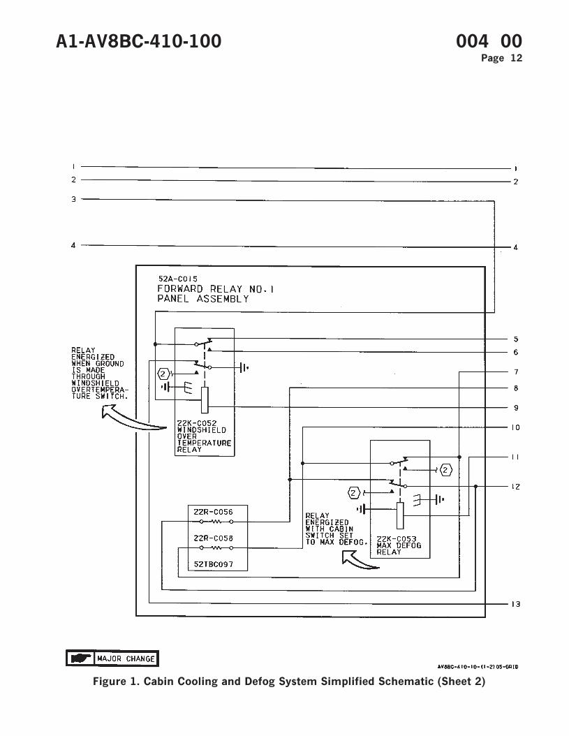
Figure 1. Cabin Cooling and Defog System Simplified Schematic (Sheet 2)
A1-AV8BC-410-100 004 00Page 12

Figure 1. Cabin Cooling and Defog System Simplified Schematic (Sheet 3)
A1-AV8BC-410-100 004 00Page 13
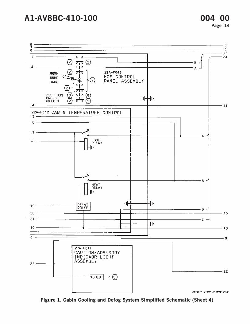
Figure 1. Cabin Cooling and Defog System Simplified Schematic (Sheet 4)
A1-AV8BC-410-100 004 00Page 14
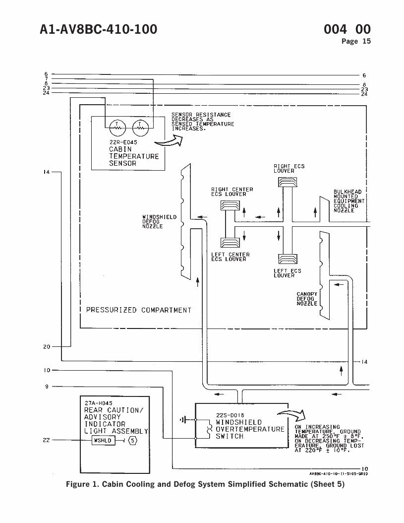
Figure 1. Cabin Cooling and Defog System Simplified Schematic (Sheet 5)
A1-AV8BC-410-100 004 00Page 15
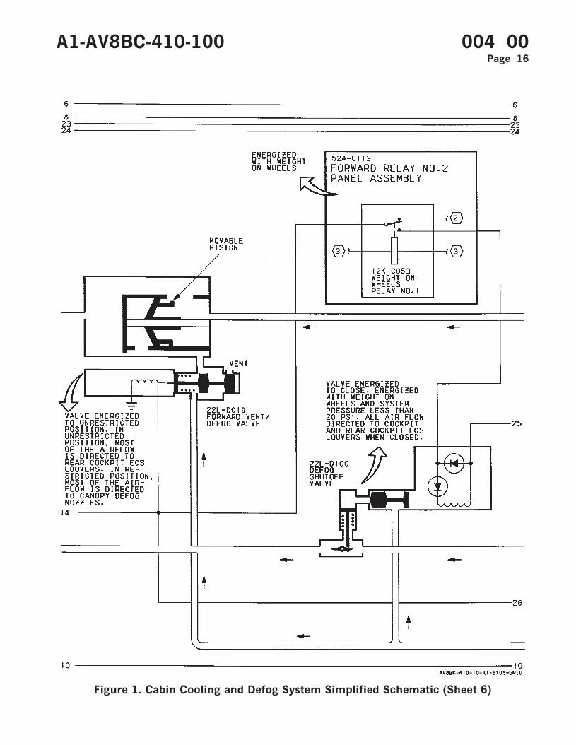
Figure 1. Cabin Cooling and Defog System Simplified Schematic (Sheet 6)
A1-AV8BC-410-100 004 00Page 16
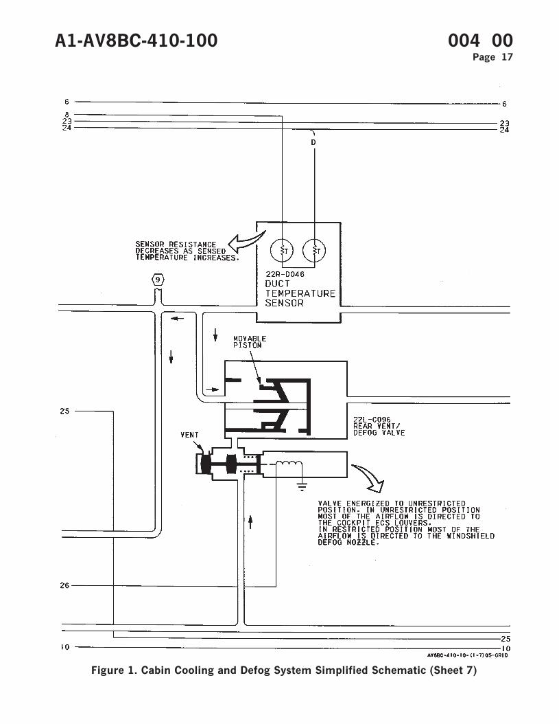
Figure 1. Cabin Cooling and Defog System Simplified Schematic (Sheet 7)
A1-AV8BC-410-100 004 00Page 17
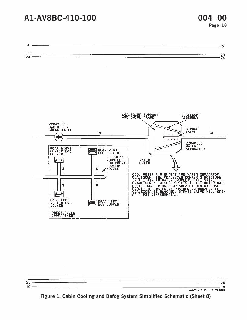
Figure 1. Cabin Cooling and Defog System Simplified Schematic (Sheet 8)
A1-AV8BC-410-100 004 00Page 18
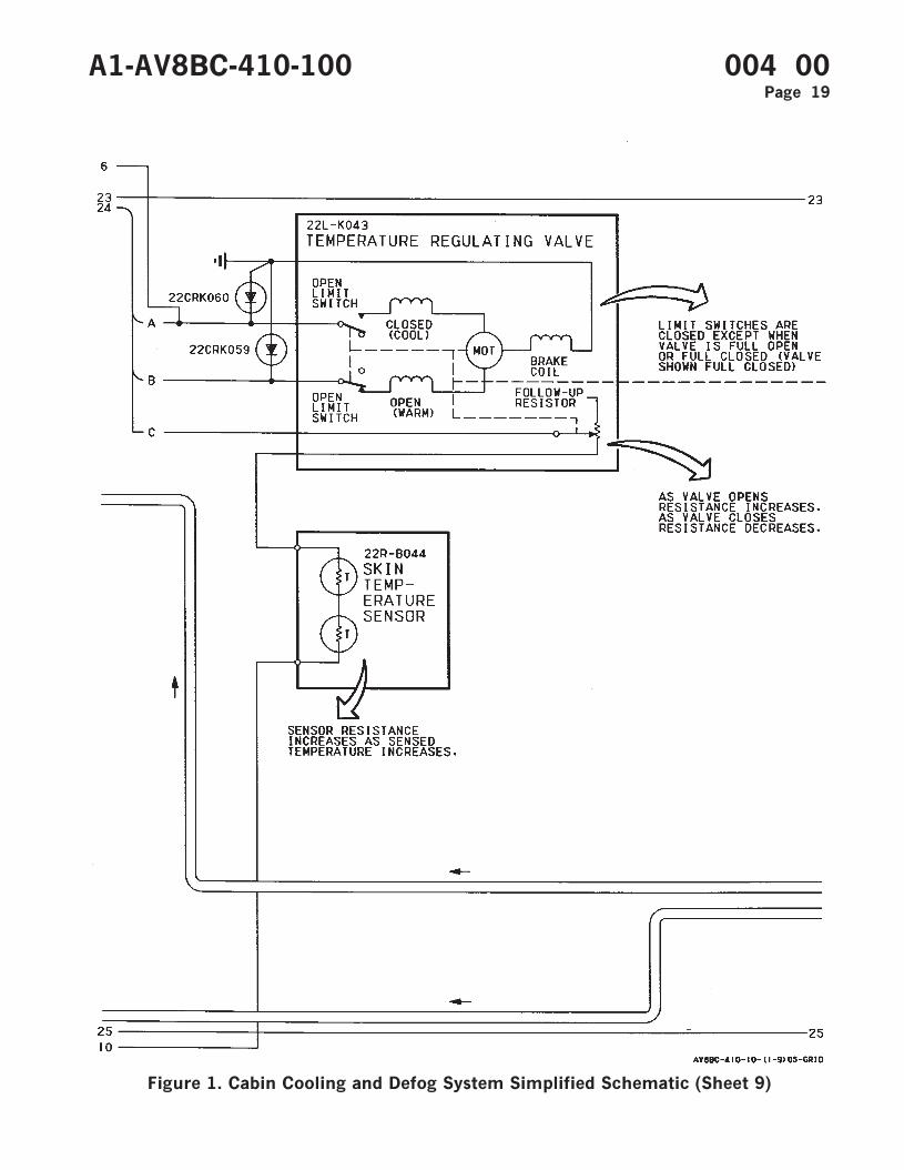
Figure 1. Cabin Cooling and Defog System Simplified Schematic (Sheet 9)
A1-AV8BC-410-100 004 00Page 19
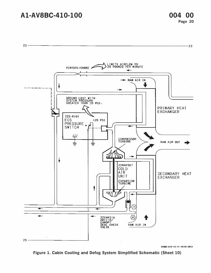
Figure 1. Cabin Cooling and Defog System Simplified Schematic (Sheet 10)
A1-AV8BC-410-100 004 00Page 20
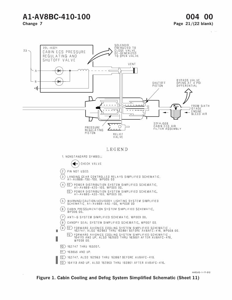
Figure 1. Cabin Cooling and Defog System Simplified Schematic (Sheet 11)
A1-AV8BC-410-100 004 00Change 7 Page 21/(22 blank)

ORGANIZATIONAL MAINTENANCE
PRINCIPLES OF OPERATION
COMPONENT LOCATOR
CABIN COOLING AND DEFOG SYSTEM
This WP supersedes WP005 00, dated 15 June 2003.
Reference Material
None
Alphabetical Index
Subject Page No.
Cabin Cooling and Defog System Component Locator, Figure 1 ........................................................ 2
Record of Applicable Technical Directives
Type/
NumberDate Title and ECP or RAMEC No.
Date
Incorp.Remarks
AV8AFC-416 — TAV-8B Polyimide Wire Replacement/Power Wire Separation (ECP MDA-AV8B-0277)
15 May 04 —
A1-AV8BC-410-100 005 00Change 7 - 15 May 2004 Page 1
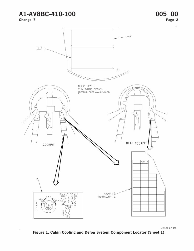
Figure 1. Cabin Cooling and Defog System Component Locator (Sheet 1)
A1-AV8BC-410-100 005 00Change 7 Page 2
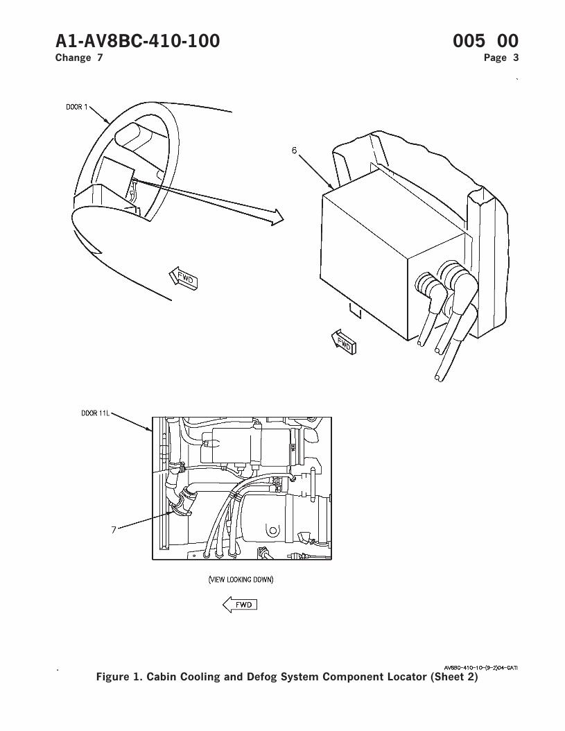
Figure 1. Cabin Cooling and Defog System Component Locator (Sheet 2)
A1-AV8BC-410-100 005 00Change 7 Page 3
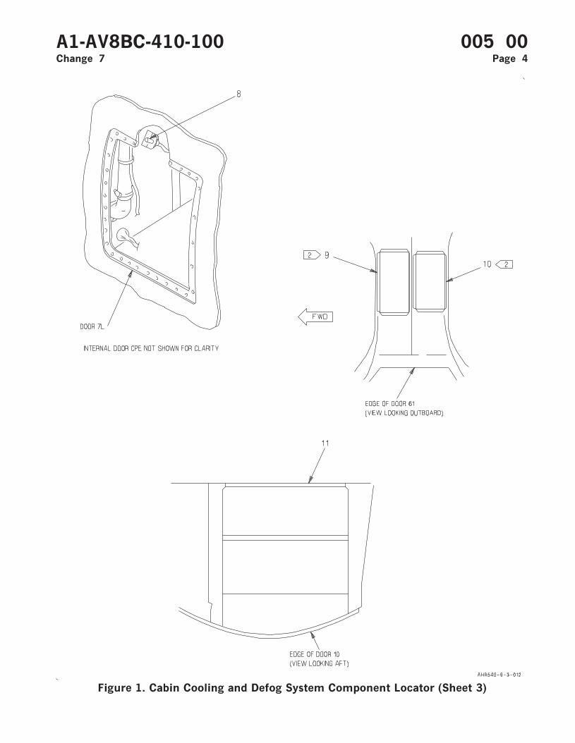
Figure 1. Cabin Cooling and Defog System Component Locator (Sheet 3)
A1-AV8BC-410-100 005 00Change 7 Page 4
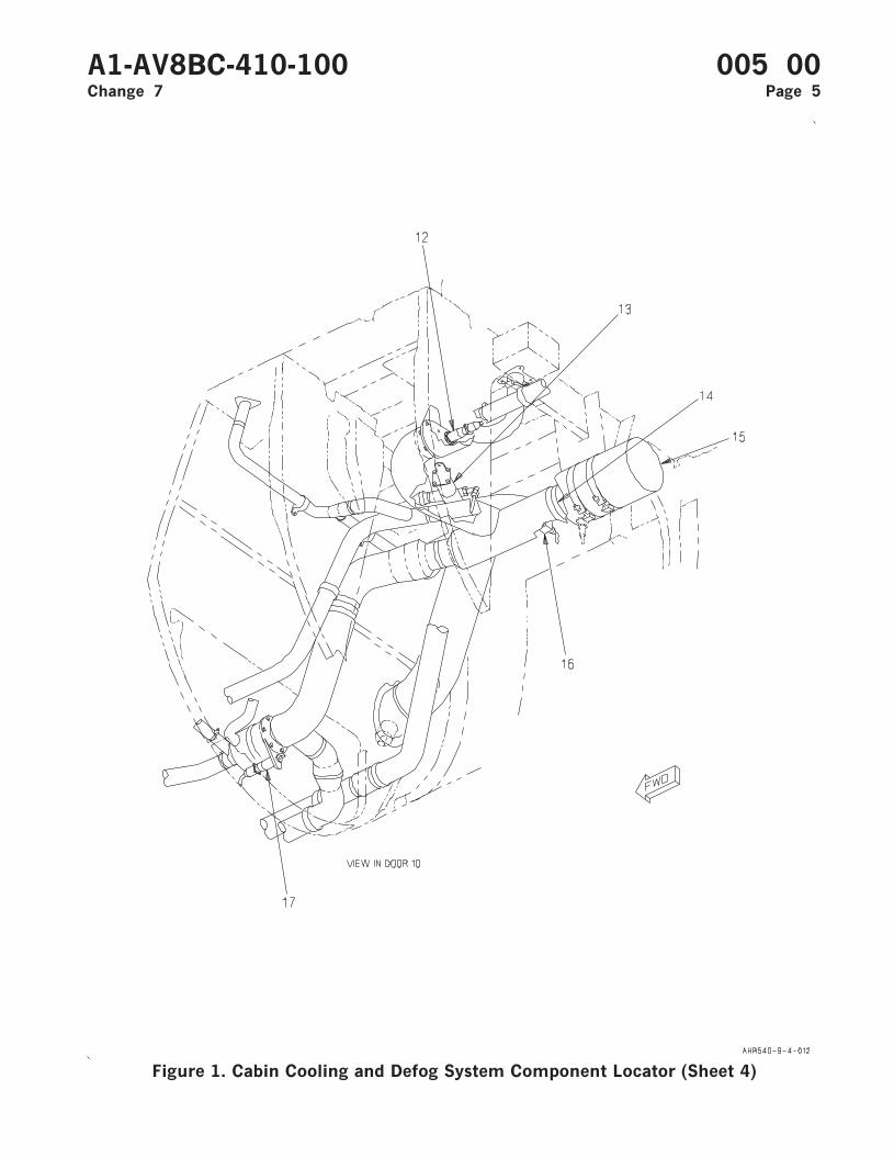
Figure 1. Cabin Cooling and Defog System Component Locator (Sheet 4)
A1-AV8BC-410-100 005 00Change 7 Page 5
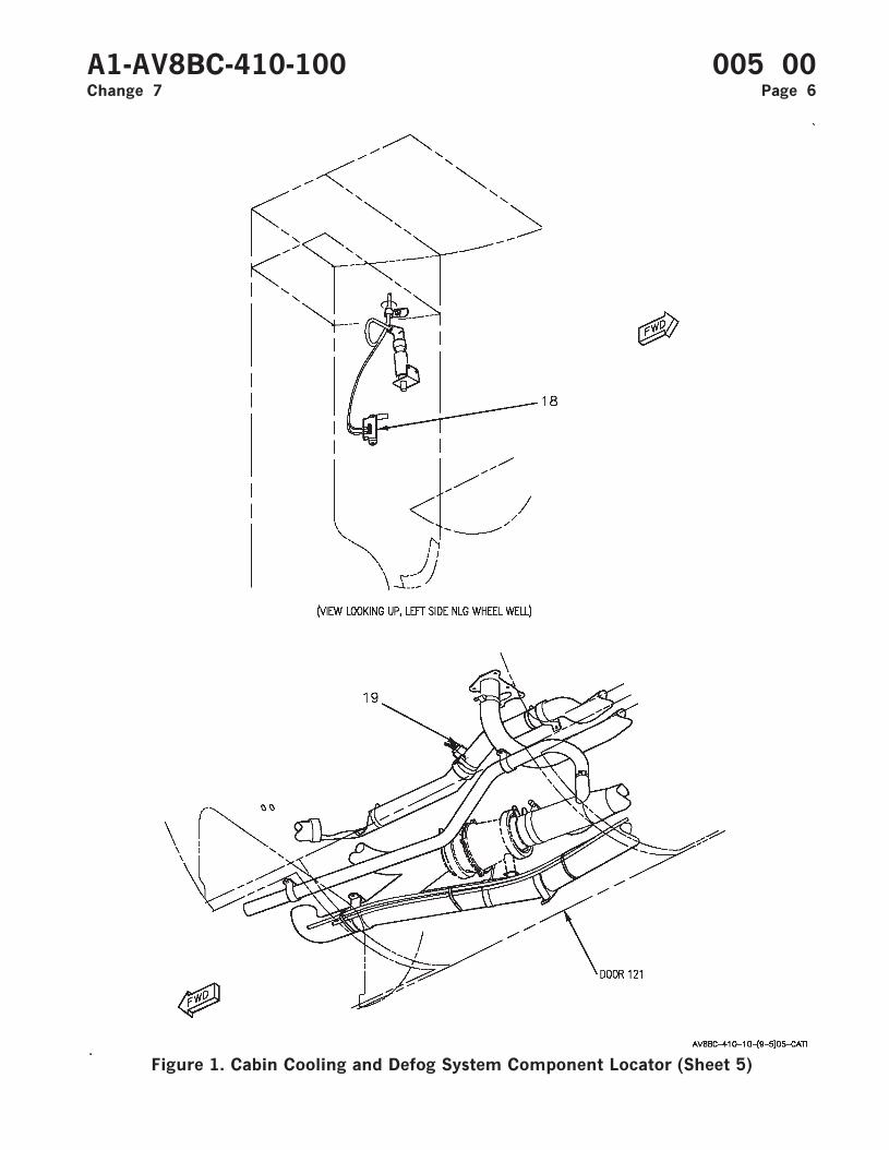
Figure 1. Cabin Cooling and Defog System Component Locator (Sheet 5)
A1-AV8BC-410-100 005 00Change 7 Page 6
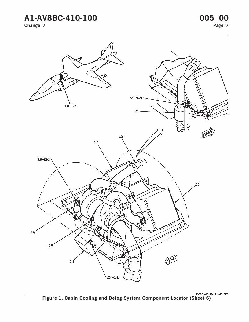
Figure 1. Cabin Cooling and Defog System Component Locator (Sheet 6)
A1-AV8BC-410-100 005 00Change 7 Page 7
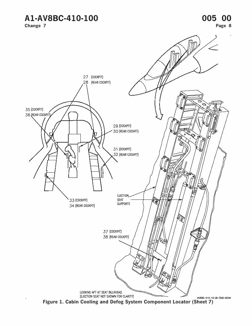
Figure 1. Cabin Cooling and Defog System Component Locator (Sheet 7)
A1-AV8BC-410-100 005 00Change 7 Page 8
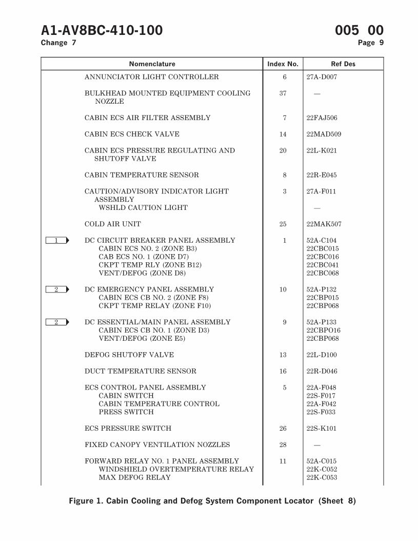
Nomenclature Index No. Ref Des
ANNUNCIATOR LIGHT CONTROLLER 6 27A-D007
BULKHEAD MOUNTED EQUIPMENT COOLINGNOZZLE
37 —
CABIN ECS AIR FILTER ASSEMBLY 7 22FAJ506
CABIN ECS CHECK VALVE 14 22MAD509
CABIN ECS PRESSURE REGULATING ANDSHUTOFF VALVE
20 22L-K021
CABIN TEMPERATURE SENSOR 8 22R-E045
CAUTION/ADVISORY INDICATOR LIGHTASSEMBLY
3 27A-F011
WSHLD CAUTION LIGHT —
COLD AIR UNIT 25 22MAK507
Ñ1 DC CIRCUIT BREAKER PANEL ASSEMBLY 1 52A-C104CABIN ECS NO. 2 (ZONE B3) 22CBC015CAB ECS NO. 1 (ZONE D7) 22CBC016CKPT TEMP RLY (ZONE B12) 22CBC041VENT/DEFOG (ZONE D8) 22CBC068
Ñ2 DC EMERGENCY PANEL ASSEMBLY 10 52A-P132CABIN ECS CB NO. 2 (ZONE F8) 22CBP015CKPT TEMP RELAY (ZONE F10) 22CBP068
Ñ2 DC ESSENTIAL/MAIN PANEL ASSEMBLY 9 52A-P133CABIN ECS CB NO. 1 (ZONE D3) 22CBPO16VENT/DEFOG (ZONE E5) 22CBP068
DEFOG SHUTOFF VALVE 13 22L-D100
DUCT TEMPERATURE SENSOR 16 22R-D046
ECS CONTROL PANEL ASSEMBLY 5 22A-F048CABIN SWITCH 22S-F017CABIN TEMPERATURE CONTROL 22A-F042PRESS SWITCH 22S-F033
ECS PRESSURE SWITCH 26 22S-K101
FIXED CANOPY VENTILATION NOZZLES 28 —
FORWARD RELAY NO. 1 PANEL ASSEMBLY 11 52A-C015WINDSHIELD OVERTEMPERATURE RELAY 22K-C052MAX DEFOG RELAY 22K-C053
A1-AV8BC-410-100 005 00Change 7 Page 9
Figure 1. Cabin Cooling and Defog System Component Locator (Sheet 8)
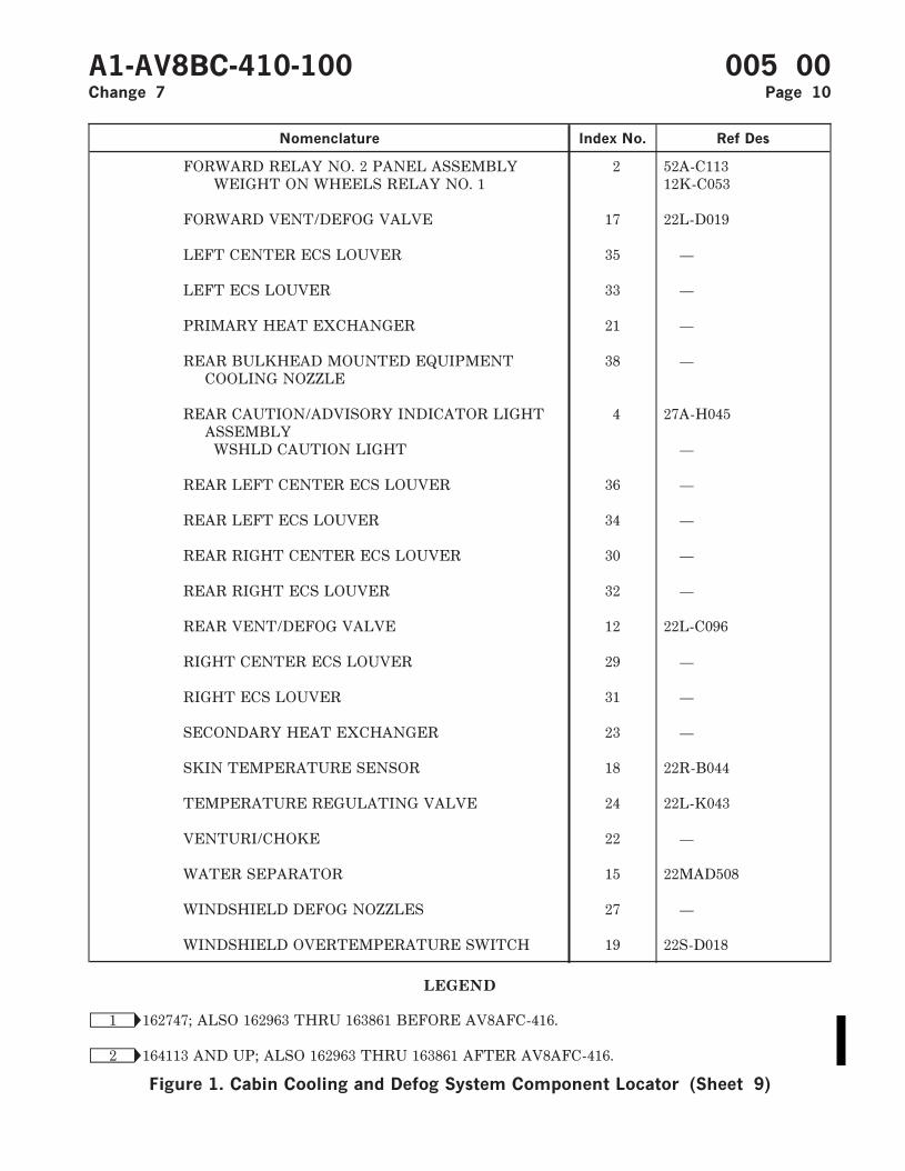
Nomenclature Index No. Ref Des
FORWARD RELAY NO. 2 PANEL ASSEMBLY 2 52A-C113WEIGHT ON WHEELS RELAY NO. 1 12K-C053
FORWARD VENT/DEFOG VALVE 17 22L-D019
LEFT CENTER ECS LOUVER 35 —
LEFT ECS LOUVER 33 —
PRIMARY HEAT EXCHANGER 21 —
REAR BULKHEAD MOUNTED EQUIPMENTCOOLING NOZZLE
38 —
REAR CAUTION/ADVISORY INDICATOR LIGHTASSEMBLY
4 27A-H045
WSHLD CAUTION LIGHT —
REAR LEFT CENTER ECS LOUVER 36 —
REAR LEFT ECS LOUVER 34 —
REAR RIGHT CENTER ECS LOUVER 30 —
REAR RIGHT ECS LOUVER 32 —
REAR VENT/DEFOG VALVE 12 22L-C096
RIGHT CENTER ECS LOUVER 29 —
RIGHT ECS LOUVER 31 —
SECONDARY HEAT EXCHANGER 23 —
SKIN TEMPERATURE SENSOR 18 22R-B044
TEMPERATURE REGULATING VALVE 24 22L-K043
VENTURI/CHOKE 22 —
WATER SEPARATOR 15 22MAD508
WINDSHIELD DEFOG NOZZLES 27 —
WINDSHIELD OVERTEMPERATURE SWITCH 19 22S-D018
LEGEND
Ñ1 162747; ALSO 162963 THRU 163861 BEFORE AV8AFC-416.
Ñ2 164113 AND UP; ALSO 162963 THRU 163861 AFTER AV8AFC-416.
A1-AV8BC-410-100 005 00Change 7 Page 10
Figure 1. Cabin Cooling and Defog System Component Locator (Sheet 9)
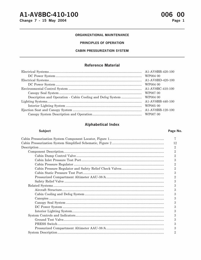
ORGANIZATIONAL MAINTENANCE
PRINCIPLES OF OPERATION
CABIN PRESSURIZATION SYSTEM
Reference Material
Electrical Systems............................................................................................................. A1-AV8BB-420-100DC Power System ..................................................................................................... WP004 00
Electrical Systems............................................................................................................. A1-AV8BD-420-100DC Power System ..................................................................................................... WP004 00
Environmental Control System ...................................................................................... A1-AV8BC-410-100Canopy Seal System ................................................................................................. WP007 00Description and Operation - Cabin Cooling and Defog System ........................ WP004 00
Lighting Systems............................................................................................................... A1-AV8BB-440-100Interior Lighting System ......................................................................................... WP005 00
Ejection Seat and Canopy System ................................................................................. A1-AV8BB-120-100Canopy System Description and Operation.......................................................... WP007 00
Alphabetical Index
Subject Page No.
Cabin Pressurization System Component Locator, Figure 1................................................................ 7Cabin Pressurization System Simplified Schematic, Figure 2 ............................................................. 12Description ................................................................................................................................................... 2
Component Description...................................................................................................................... 2Cabin Dump Control Valve ....................................................................................................... 2Cabin Inlet Pressure Test Port................................................................................................. 3Cabin Pressure Regulator .......................................................................................................... 2Cabin Pressure Regulator and Safety Relief Check Valves.................................................. 2Cabin Static Pressure Test Port ............................................................................................... 3Pressurized Compartment Altimeter AAU-38/A.................................................................... 2Safety Relief Valve ..................................................................................................................... 3
Related Systems .................................................................................................................................. 3Aircraft Structure........................................................................................................................ 3Cabin Cooling and Defog System ............................................................................................. 3Canopies ....................................................................................................................................... 3Canopy Seal System ................................................................................................................... 3DC Power System ....................................................................................................................... 3Interior Lighting System............................................................................................................ 3
System Controls and Indicators........................................................................................................ 3Ground Test Valve...................................................................................................................... 3PRESS Switch ............................................................................................................................. 3Pressurized Compartment Altimeter AAU-38/A.................................................................... 3
System Description ............................................................................................................................. 2
A1-AV8BC-410-100 006 00Change 7 - 15 May 2004 Page 1

Alphabetical Index (Continued)
Subject Page No.
Operation...................................................................................................................................................... 4Component Operation ........................................................................................................................ 4
Cabin Dump Control Valve ....................................................................................................... 4Cabin Inlet Pressure Test Port................................................................................................. 5Cabin Pressure Regulator .......................................................................................................... 4Cabin Pressure Regulator Check Valve ................................................................................... 4Cabin Static Pressure Test Port ............................................................................................... 5Safety Relief Check Valve ......................................................................................................... 4Safety Relief Valve ..................................................................................................................... 5
System Operation................................................................................................................................ 5Dump ............................................................................................................................................ 6Ground Test................................................................................................................................. 6Normal Flight .............................................................................................................................. 5
Record of Applicable Technical Directives
Type/
NumberDate Title and ECP or RAMEC No.
Date
Incorp.Remarks
AV8AFC-416 — TAV-8B Polyimide Wire Replacement/Power Wire Separation (ECP MDA-AV8B-0277)
15 May 04 —
1. DESCRIPTION.
2. SYSTEM DESCRIPTION. The cabin ispressurized by conditioned air from the cabincooling and defog system (WP004 00) to provide acomfortable, less fatiguing environment for thepilot. Pressurization is done by controlling the rateof airflow from the sealed cabin. The airflow isrouted to equipment bays, where it augmentsavionics cooling.
3. COMPONENT DESCRIPTION. Systemcomponents shown in figure 1 are described andlisted in paragraphs below.
4. Cabin Dump Control Valve. The cabin dumpcontrol valve is a solenoid operated, two position aircontrol valve. The valve is made up of a body withinlet and outlet connections and a solenoid with anelectrical connection. The solenoid is mounted tothe valve body.
5. Cabin Pressure Regulator and Safety Relief
Check Valves. The cabin pressure regulator andsafety relief check valves are poppet type, in line
check valves. The valve body is threaded at eachend.
6. Cabin Pressure Regulator. The cabin pressureregulator is an outflow valve and a self containedcontroller in a single unit. The outflow valve ismade up of a base, outflow valve, actuatordiaphragm, valve return spring, and a controlchamber. The base includes the valve seat andforms the passage for discharge air from thepressurized area. The controller is made up of anorifice, filter, ground test valve, and two controlsystems: the isobaric control system and thedifferential control system.
7. Pressurized Compartment Altimeter AAU-38/A.
The Pressurized Compartment Altimeter AAU-38/Ais a self contained aneroid, single pointer, integrallylighted instrument. The altimeter measures andindicates cabin pressure from 0 to 50,000 feet. Thealtimeter face is graduated every 1000 feet, majorincrements each 5000 feet, and markings at theeven major increments.
A1-AV8BC-410-100 006 00Change 7 Page 2
8. Safety Relief Valve. The safety relief valve is anoutflow valve made up of a head section and a basesection. The head section consists of a pressurerelief metering valve, pressure relief calibrationspring and two pressure relief control diaphragms.The base section consists of an outflow valve,mounting base and operating mechanism. Theoutflow valve provides the passage for discharge airfrom the pressurized area.
9. Cabin Inlet Pressure Test Port. The cabin inletpressure test port is a capped port installed throughthe rear cockpit floor.
10. Cabin Static Pressure Test Port. The cabinstatic pressure test port is a capped port installedthrough the rear cockpit floor.
11. RELATED SYSTEMS. Related systems aredescribed in paragraphs below.
12. Cabin Cooling and Defog System. The cabincooling and defog system (WP004 00) providesconditioned air to pressurize the cabin. Air entersthe sealed cabin through the cockpit ECS louvers,windshield defog nozzles and fixed canopyventilation nozzles.
13. Canopy Seal System. The canopy seal system(WP007 00) provides an inflatable seal interfacebetween the forward canopy, aft canopy, windshieldarch, fixed canopy, and aircraft structure.
14. Interior Lighting System. The interior lightingsystem (A1-AV8BB-440-100, WP005 00) providesillumination for the Pressurized CompartmentAltimeter AAU-38/A. Rotating the CONSL control,on the INTR LT control panel, varies altimeterlighting from off to bright. A lights test function isalso provided.
15. Aircraft Structure. Cockpit floors, aft seatbulkhead, aircraft side skins, forward pressurebulkhead, windshield, and fixed canopy provide thepressurized area.
16. Canopies. The forward and aft canopies(A1-AV8BB-120-100, WP007 00), when lockedclosed, complete the pressurized area.
17. DC Power System. The DC power system on162747; ALSO 162963 THRU 163861 BEFOREAV8AFC-416 (A1-AV8BB-420-100, WP004 00) or164113 AND UP; ALSO 162963 THRU 163861
AFTER AV8AFC-416 (A1-AV8BD-420-100, WP00400) supplies emergency 28vdc power for the cabinpressurization system.
18. SYSTEM CONTROLS AND INDICATORS.
System controls and indicators are described inparagraphs below.
19. PRESS Switch. The PRESS switch, located onthe ECS control panel assembly, is a four pole leverlock toggle switch. The switch provides modeselection for cabin pressurization and on/off controlof the cabin cooling and defog system. Refer toWP004 00 for cabin cooling and defog system. Theswitch has three positions; NORM, DUMP, andRAM. The switch is locked in all positions.
20. Setting the switch to DUMP or RAM fromNORM, applies emergency 28vdc power to energizethe cabin dump control valve.
21. Setting the switch to NORM from RAM orDUMP, removes emergency 28vdc power todeenergize the cabin dump control valve.
22. Pressurized Compartment Altimeter
AAU-38/A. The Pressurized CompartmentAltimeter AAU-38/A is located in the cockpit on theright vertical console. The altimeter senses andindicates cabin altitude. Cabin altitude is artificiallycreated by the cabin pressurization system byregulating pressurized air exiting the sealed cabin.The altimeter has an aneroid (evacuated bellows)which expands and contracts in response to sensedchanges in pressure. As the aneroid moves, amechanical linkage moves the pointer to indicatecabin altitude.
23. The pilot can use the cabin altitude to comparewith aircraft altitude. With this comparison, thepilot can determine whether the cabin is over,under, or correctly pressurized.
24. Illumination of the altimeter is provided by theinterior lighting system.
25. Ground Test Valve. The ground test valve,located on the face of the cabin pressure regulator,is a manually operated three position selector valve.The valve handle is rotated to select normal flightor test positions. The three settings are FLIGHT,TEST ONLY DIFF ON, and TEST ONLY ALLOFF.
26. The FLIGHT position is used to provideautomatic in-flight cabin pressurization control.
A1-AV8BC-410-100 006 00Change 7 Page 3
Cabin pressure will maintain the prescribedschedule as the aircraft altitude increases ordecreases. The valve handle is lockwired to theFLIGHT position.
27. The TEST ONLY DIFF ON position is used totest the differential control portion of the cabinpressure regulator. Setting the handle to thisposition, renders the isobaric control portion of theregulator inoperative by closing the isobaricmetering valve outlet. Only the differential controlportion will operate.
28. The TEST ONLY ALL OFF position is used totest safety relief valve operation. Setting the handleto this position renders both the isobaric anddifferential control positions of the regulatorinoperative by closing both the isobaric anddifferential metering valve outlets. The regulatorwill not operate and cabin pressure will becontrolled by the safety relief valve.
29. OPERATION.
30. COMPONENT OPERATION.
NOTE
During normal operation of the cabinpressurization system, cabin pressure iscontrolled by air pressure measured inpounds per square inch (psi). Cabinpressure is the difference between cabinatmospheric pressure and ambientatmospheric pressure, expressed inpounds per square inch differential(psid). The psid value is used only duringground testing of the system. Duringnormal flight, the cabin pressure isexpressed as pressure altitude.
31. Cabin Dump Control Valve. The cabin dumpcontrol valve is located in the rear cockpit underthe right vertical console. The valve is connectedpneumatically to the cabin pressure regulator andsafety relief valve. The valve allows the pilot torapidly remove (dump) cabin pressure, if required.
32. Valve operation is controlled by the PRESSswitch. With the valve deenergized, spring pressurein the valve closes the valve poppet. The poppetprevents control chamber pressure in the cabinpressure regulator and safety relief valve fromventing to atmosphere. This allows normaloperation of the regulator and relief valve.
33. With the valve energized, cabin pressureregulator and safety relief valve control chamberpressure is lost. Spring tension will open bothregulator and relief valve allowing cabin pressure todump.
34. Cabin Pressure Regulator Check Valve. Thecabin pressure regulator check valve is located indoor 1 in the cabin pressure regulator atmosphericvent line. The check valve will prevent a dualfailure if the safety relief valve fails or leaksinternally.
35. The cabin pressure regulator and safety reliefvalve control chambers are connectedpneumatically. Without the check valve installed inthe atmospheric vent line, if the safety relief valvefailed or developed an internal leak, regulatorcontrol chamber pressure would also be lost. Thecheck valve prevents control chamber pressure loss.
36. Safety Relief Check Valve. The safety reliefcheck valve is located in the rear cockpit under theright vertical console in the atmospheric port of thesafety relief valve. The check valve will prevent adual failure if the cabin pressure regulator fails orleaks internally.
37. The safety relief valve and cabin pressureregulator control chambers are connectedpneumatically. Without the check valve installed inthe atmospheric vent line, relief valve controlchamber pressure would be lost if the regulatordeveloped an internal leak or failed. The checkvalve prevents control chamber pressure loss.
38. Cabin Pressure Regulator. The cabin pressureregulator, located outside the pressurizedcompartment in door 1, automatically controls cabinpressure throughout the aircraft flight envelope.The regulator has a three mode normal operatingcapability and a two mode ground test capability.
39. During normal flight, the regulator ground testvalve handle is set to FLIGHT. This allows theregulator to operate in its three normal modes;unpressurized, isobaric, and differential.
40. In the unpressurized mode, pressure in thecabin is maintained slightly higher thanatmospheric pressure. The unpressurized mode isfrom sea level to approximately 8000 feet. Controlchamber pressure is enough to compress theisobaric bellows, keeping the isobaric metering valveopen to the atmosphere. Control chamber pressure
A1-AV8BC-410-100 006 00Change 6 Page 4

is cabin air that has entered the control chamberthrough the air filter and orifice. Since the orifice issmaller than the open isobaric metering valve port,control chamber pressure is slightly lower thanoutflow valve spring tension. The outflow valve willremain open, venting cabin air to atmosphere. Since
the amount of air venting from the cabin is lessthan the amount of air entering the cabin, cabinpressure will be slightly higher than ambientpressure. This mode will function until the aircraftaltitude is approximately 8000 feet. The isobaricmode will then function.
A1-AV8BC-410-100 006 00Change 6 Page 4A/(4B blank)

41. In the isobaric mode, cabin pressure ismaintained at a pressure equal to approximately8000 feet while aircraft altitude is approximately8000 to 23,100 feet.
42. Control chamber pressure constantly decreaseswith an increase in aircraft altitude. The decreasedcontrol chamber pressure cannot compress theisobaric bellows as much and the isobaric meteringbellows begin to close. As metering valve closes, lesscontrol chamber pressure is vented. Pressurecoming into the control chamber through the orificeand pressure venting to atmosphere through thenow closing metering valve is balanced as aircraftaltitude increases from 8000 to approximately23,100 feet. The balanced pressures allow the cabinpressure regulator to maintain a constant cabinpressure in the isobaric mode.
43. As aircraft altitude increases aboveapproximately 23,100 feet, the isobaric meteringvalve is fully closed. Closing the metering valvebuilds sufficient control chamber pressure to beginthe differential mode of operation.
44. In the differential mode, cabin pressure ismaintained at a constant differential pressureversus ambient pressure. The constant differentialpressure is 5.00 ±0.23 psid.
45. As aircraft altitude exceeds approximately23,100 feet, the increasing control chamber pressureovercomes spring tension and moves the differentialdiaphragm mechanism. Moving the mechanismopens the differential metering valve which ventscontrol chamber pressure. The venting causes alower control chamber pressure which allows springtension to open the outflow valve. The open valvevents enough cabin pressure to maintain a constantdifferential pressure of 5.00 ±0.23 psid betweencabin and ambient.
46. Safety Relief Valve. The safety relief valve islocated in the rear cockpit under the right verticalconsole. The valve will limit cabin pressure to 5.35±0.23 psid and provide negative pressure relief.
47. Cabin pressure enters the control chamberthrough the air filter screen. Control chamberpressure overrides outflow valve return springtension and holds the outflow valve closed throughthe cabin pressure schedule. As control chamberpressure increases with cabin pressure to 5.35 ±0.23psid, control chamber pressure acts on the meteringvalve assembly diaphragm. Pressure on the
diaphragm overrides the pressure relief calibrationspring. The metering valve assembly moves and themetering valve is off seated by the pressure reliefcalibration screw. The open metering valve ventsthe control chamber and allows the outflow valvereturn spring to open the outflow valve and ventexcess cabin pressure. The safety relief valve workswith smooth modulation rather than erratic relief.
48. Negative pressure is ambient pressure greaterthan cabin pressure. This occurs during rapidaircraft descent. Normal operation of the systemcannot always react to change cabin pressure as fastas the aircraft can descend. When this occurs, thesafety relief valve will open and allow ambientpressure to enter the cabin to equalize pressure.
49. The higher ambient pressure overrides thelower cabin and control chamber pressure andoutflow valve return spring. The higher ambientpressure moves the outflow valve open to allowambient pressure to enter the cabin. As thepressures equalize, the outflow valve will closeunder pressure from the outflow valve returnspring.
50. Cabin Inlet Pressure Test Port. The cabin inletpressure test port is located in the nose landing gearwheelwell. The test port allows a ground air sourceand a cabin pressure tester to be used for groundtesting of the cabin pressurization system. The testport allows the external air to enter the cabin.
51. Cabin Static Pressure Test Port. The cabinstatic pressure test port is located in the noselanding gear wheelwell. The test port allows aground air source and a cabin pressure tester to beused for ground testing of the cabin pressurizationsystem. The test port allows the cabin pressure tobe measured externally.
52. SYSTEM OPERATION.
53. Conditioned air from the cabin cooling anddefog system (WP004 00) is controlled to maintaincabin pressure. The system operates in three modes,normal flight, ground test, and dump.
54. Normal Flight. During normal flight, airpressure entering the cabin also enters the controlchambers of the cabin pressure regulator and thesafety relief valve. The relief valve will remainclosed until cabin pressure exceeds 5.35 ±0.23 psid.The control chamber pressure in the regulator isnot enough to close the outflow valve from sea level
A1-AV8BC-410-100 006 00Page 5
to 8000 feet. Thus, cabin pressure will remain atslightly above ambient pressure until the aircraftarrives at 8000 feet.
55. As the aircraft reaches 8000 feet, cabin pressureentering the regulator control chamber is enough toact on the isobaric bellows which begins to moveand close the isobaric metering valve. The closingmetering valve allows control chamber pressure tobuild and close the outflow valve as required tomaintain a cabin altitude of 8000 feet while aircraftaltitude increases from 8000 to 23,100 feet.
56. As the aircraft reaches 23,100 feet, cabinpressure entering the regulator control chamber hasfully closed the isobaric metering valve and beginsto open the differential metering valve. The openingdifferential metering valve vents control chamberpressure to allow the regulator to maintain 5.00±0.23°ba psid between cabin and ambient pressure.This schedule is maintained from 23,100 feet andhigher.
57. If cabin pressure exceeds the regulator setting,the safety relief valve will open and relieve pressure.As cabin pressure increases to 5.35 ±0.23 psid,control pressure in the relief valve which has held itclosed is vented and the outflow valve return springopens the valve.
58. In the event of negative cabin pressure, (cabinpressure less than ambient pressure) the lowercontrol chamber pressure in the safety relief valve isnot enough to hold the valve closed. The outflow
valve return spring opens the valve to equalizepressure.
59. Ground Test. The cabin pressure regulator hasa ground test valve which allows the system to betested on the ground. The ground test has twomodes, TEST ONLY DIFF ON and TEST ONLYALL OFF. The TEST ONLY DIFF ON modeallows the cabin pressure regulator to bypass theunpressurized and isobaric modes and maintaincabin pressure at the 5.00 ±0.23 psid differentialmode. The TEST ONLY ALL OFF mode allows thesafety relief valve to regulate cabin pressure at 5.35±0.23 psid and bypass the regulator setting entirely.
60. During ground testing, an external air sourceand special test equipment is required. Three testfittings are located in the nose landing gearwheelwell for test equipment hookup. One portprovides an air inlet to the cabin, one providescabin pressure sensing, and one provides pressure tothe canopy pressure seal. Refer to WP007 00 forcanopy seal system.
61. Dump. The dump mode allows all cabinpressure to be removed (dump) from the cabin. Iffumes or smoke enter the cabin, the pilot can selectDUMP with the PRESS switch. This will open thecabin dump control valve, venting control chamberpressure and opening the cabin pressure regulatorand relief valve. Cabin pressure drops and vents thecabin. Selecting RAM with the PRESS switch willalso dump cabin pressure and disable the cabincooling and defog system (WP004 00).
A1-AV8BC-410-100 006 00Page 6

Figure 1. Cabin Pressurization System Component Locator (Sheet 1)
A1-AV8BC-410-100 006 00Page 7
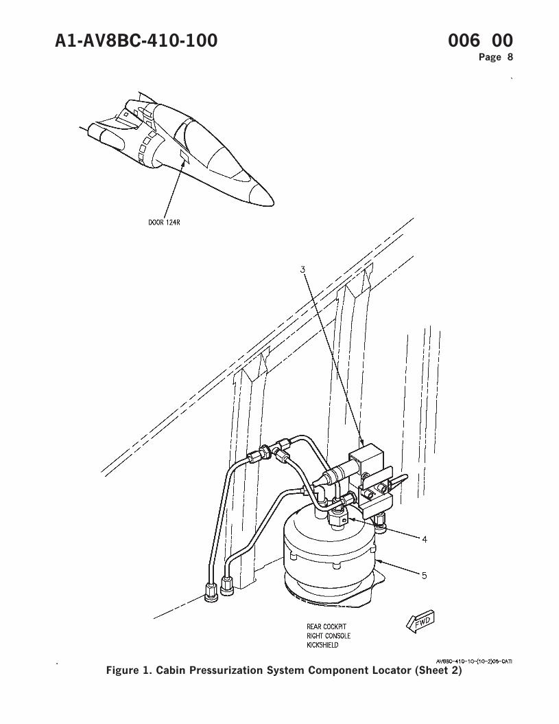
Figure 1. Cabin Pressurization System Component Locator (Sheet 2)
A1-AV8BC-410-100 006 00Page 8
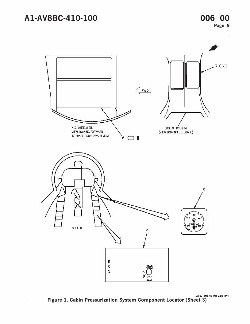
Figure 1. Cabin Pressurization System Component Locator (Sheet 3)
A1-AV8BC-410-100 006 00Page 9
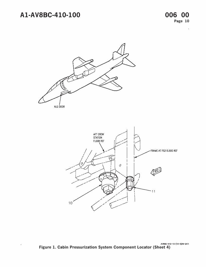
Figure 1. Cabin Pressurization System Component Locator (Sheet 4)
A1-AV8BC-410-100 006 00Page 10
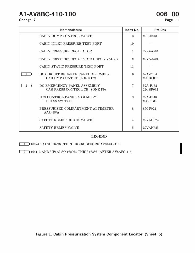
Nomenclature Index No. Ref Des
CABIN DUMP CONTROL VALVE 3 22L-H034
CABIN INLET PRESSURE TEST PORT 10 —
CABIN PRESSURE REGULATOR 1 22VAA504
CABIN PRESSURE REGULATOR CHECK VALVE 2 22VAA501
CABIN STATIC PRESSURE TEST PORT 11 —
Ñ1 DC CIRCUIT BREAKER PANEL ASSEMBLY 6 52A-C104CAB DMP CONT CB (ZONE B2) 22CBC032
Ñ2 DC EMERGENCY PANEL ASSEMBLY 7 52A-P132CAB PRESS CONTROL CB (ZONE F9) 22CBP032
ECS CONTROL PANEL ASSEMBLY 9 22A-F048PRESS SWITCH 22S-F033
PRESSURIZED COMPARTMENT ALTIMETERAAU-38/A
8 8M-F072
SAFETY RELIEF CHECK VALVE 4 22VAH524
SAFETY RELIEF VALVE 5 22VAH525
LEGEND
Ñ1 162747; ALSO 162963 THRU 163861 BEFORE AV8AFC-416.
Ñ2 164113 AND UP; ALSO 162963 THRU 163861 AFTER AV8AFC-416.
A1-AV8BC-410-100 006 00Change 7 Page 11
Figure 1. Cabin Pressurization System Component Locator (Sheet 5)

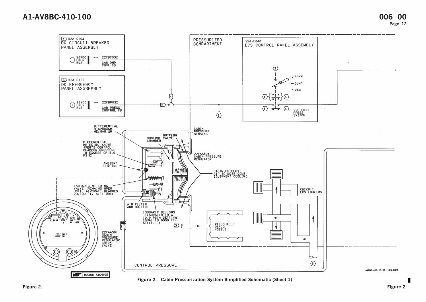
Figure 2. Cabin Pressurization System Simplified Schematic (Sheet 1)
A1-AV8BC-410-100 006 00Page 12
Figure 2. Figure 2.
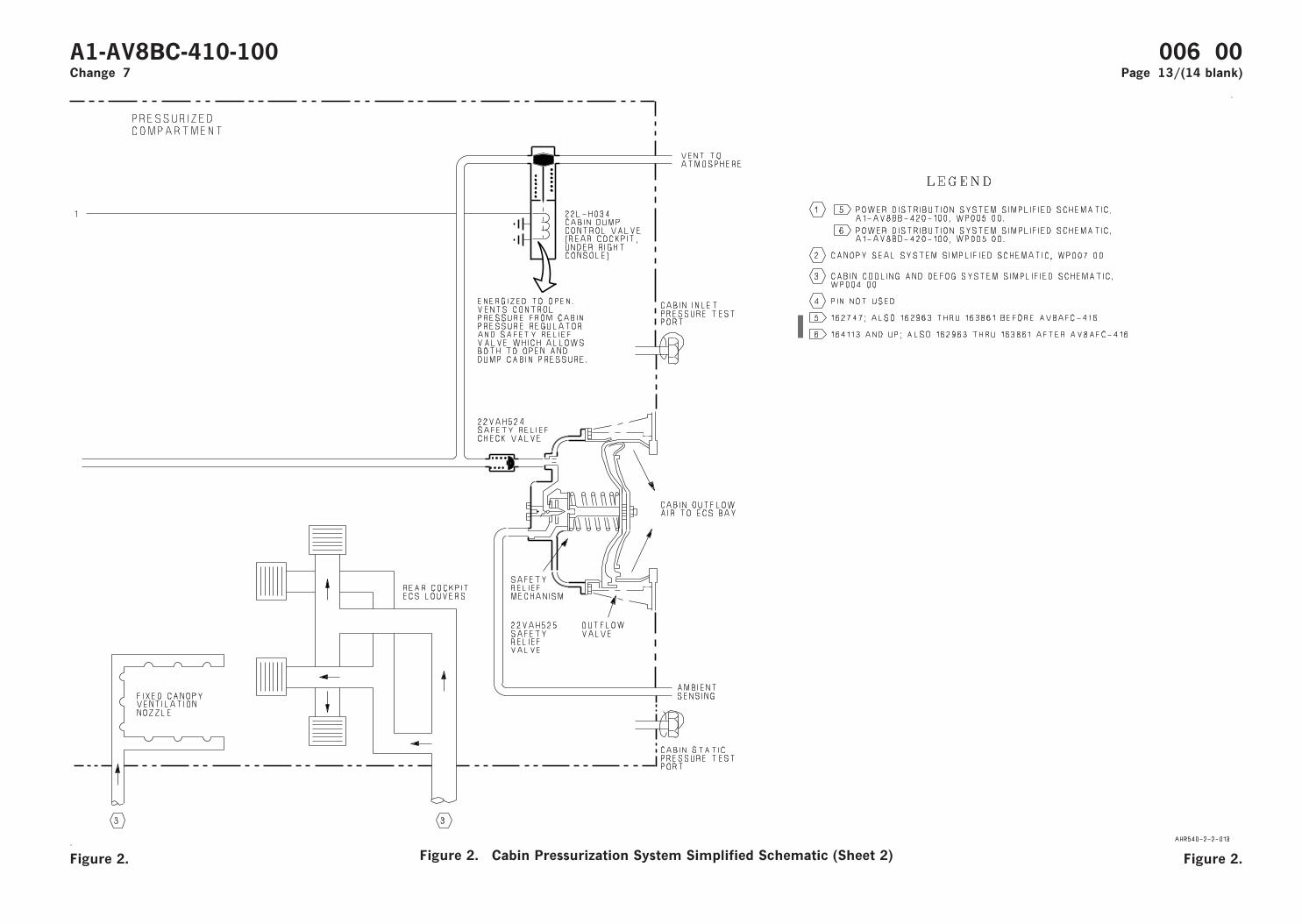
Figure 2. Cabin Pressurization System Simplified Schematic (Sheet 2)
A1-AV8BC-410-100 006 00Change 7 Page 13/(14 blank)
Figure 2. Figure 2.
ORGANIZATIONAL MAINTENANCE
PRINCIPLES OF OPERATION
CANOPY SEAL SYSTEM
Reference Material
Ejection Seat and Canopy System ................................................................................. A1-AV8BB-120-100Canopy System Description and Operation.......................................................... WP007 00
Environmental Control System ...................................................................................... A1-AV8BC-410-100Description and Operation - Cabin Cooling and Defog System ........................ WP004 00Description and Operation - Cabin Pressurization System................................ WP006 00Description and Operation - Anti-G System ........................................................ WP009 00
Electrical Systems............................................................................................................. A1-AV8BB-420-100DC Power System ..................................................................................................... WP004 00
Electrical Systems............................................................................................................. A1-AV8BD-420-100DC Power System ..................................................................................................... WP004 00
Landing Gear and Related Systems............................................................................... A1-AV8BB-130-100Landing Gear System............................................................................................... WP003 00
Alphabetical Index
Subject Page No.
Canopy Seal System Component Locator, Figure 1 .............................................................................. 5Canopy Seal System Simplified Schematic, Figure 2............................................................................ 10Description ................................................................................................................................................... 2
Component Description...................................................................................................................... 2Aft Canopy Pressure Seal .......................................................................................................... 2Anti-G/Canopy Seal Check Valve............................................................................................. 2Anti-G/Canopy Seal Test Port.................................................................................................. 2Canopy Seal Control Valve........................................................................................................ 2Canopy Seal Pressure Regulator and Check Valve................................................................ 2Forward Canopy Pressure Seal ................................................................................................. 2
Related Systems .................................................................................................................................. 2Aircraft Structure........................................................................................................................ 3Cabin Cooling and Defog System ............................................................................................. 2Canopy System............................................................................................................................ 2DC Power System ....................................................................................................................... 2ALanding Gear and Related Systems......................................................................................... 2A
System Control and Indicators ......................................................................................................... 3Press Switch................................................................................................................................. 3
System Description ............................................................................................................................. 2Operation...................................................................................................................................................... 3
Component Operation ........................................................................................................................ 3Aft Canopy Pressure Seal .......................................................................................................... 3Anti-G/Canopy Seal Check Valve............................................................................................. 3
A1-AV8BC-410-100 007 00Change 7 - 15 May 2004 Page 1
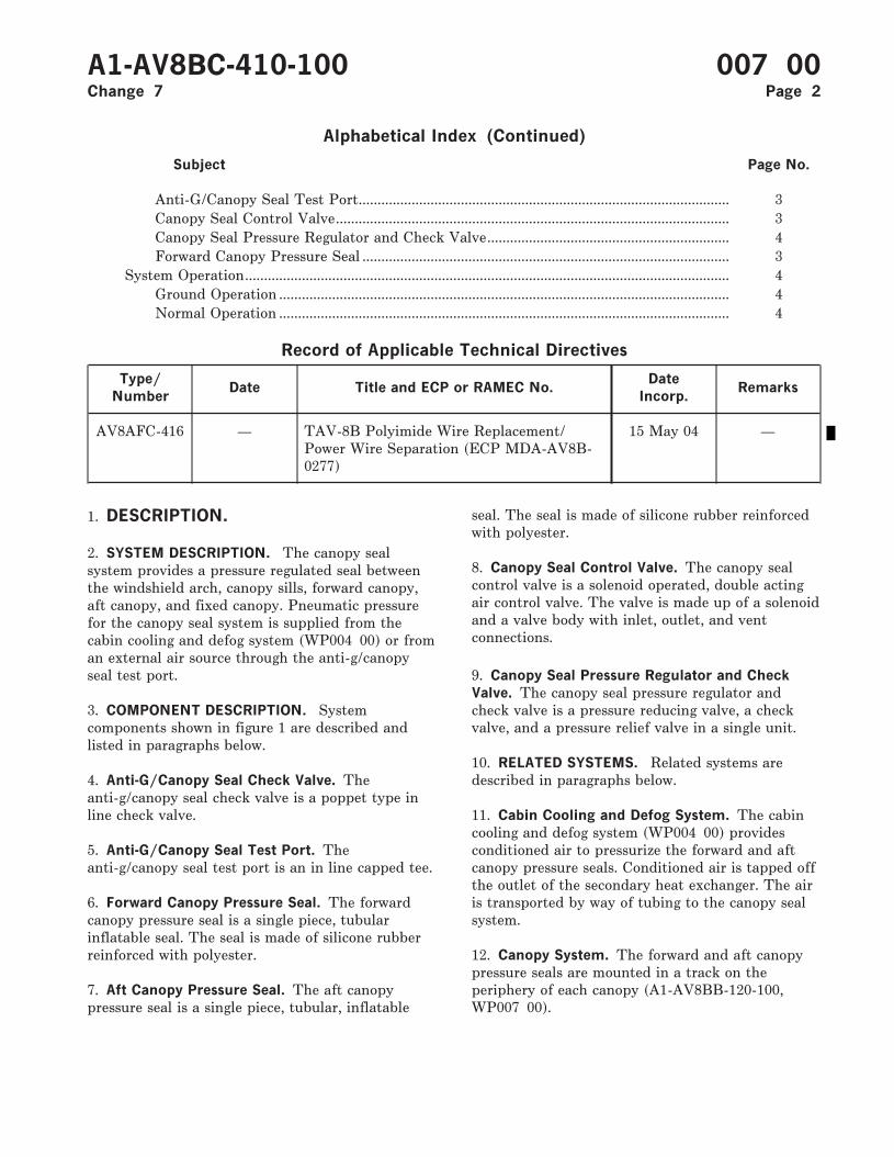
Alphabetical Index (Continued)
Subject Page No.
Anti-G/Canopy Seal Test Port.................................................................................................. 3Canopy Seal Control Valve........................................................................................................ 3Canopy Seal Pressure Regulator and Check Valve................................................................ 4Forward Canopy Pressure Seal ................................................................................................. 3
System Operation................................................................................................................................ 4Ground Operation ....................................................................................................................... 4Normal Operation ....................................................................................................................... 4
Record of Applicable Technical Directives
Type/
NumberDate Title and ECP or RAMEC No.
Date
Incorp.Remarks
AV8AFC-416 — TAV-8B Polyimide Wire Replacement/Power Wire Separation (ECP MDA-AV8B-0277)
15 May 04 —
1. DESCRIPTION.
2. SYSTEM DESCRIPTION. The canopy sealsystem provides a pressure regulated seal betweenthe windshield arch, canopy sills, forward canopy,aft canopy, and fixed canopy. Pneumatic pressurefor the canopy seal system is supplied from thecabin cooling and defog system (WP004 00) or froman external air source through the anti-g/canopyseal test port.
3. COMPONENT DESCRIPTION. Systemcomponents shown in figure 1 are described andlisted in paragraphs below.
4. Anti-G/Canopy Seal Check Valve. Theanti-g/canopy seal check valve is a poppet type inline check valve.
5. Anti-G/Canopy Seal Test Port. Theanti-g/canopy seal test port is an in line capped tee.
6. Forward Canopy Pressure Seal. The forwardcanopy pressure seal is a single piece, tubularinflatable seal. The seal is made of silicone rubberreinforced with polyester.
7. Aft Canopy Pressure Seal. The aft canopypressure seal is a single piece, tubular, inflatable
seal. The seal is made of silicone rubber reinforcedwith polyester.
8. Canopy Seal Control Valve. The canopy sealcontrol valve is a solenoid operated, double actingair control valve. The valve is made up of a solenoidand a valve body with inlet, outlet, and ventconnections.
9. Canopy Seal Pressure Regulator and Check
Valve. The canopy seal pressure regulator andcheck valve is a pressure reducing valve, a checkvalve, and a pressure relief valve in a single unit.
10. RELATED SYSTEMS. Related systems aredescribed in paragraphs below.
11. Cabin Cooling and Defog System. The cabincooling and defog system (WP004 00) providesconditioned air to pressurize the forward and aftcanopy pressure seals. Conditioned air is tapped offthe outlet of the secondary heat exchanger. The airis transported by way of tubing to the canopy sealsystem.
12. Canopy System. The forward and aft canopypressure seals are mounted in a track on theperiphery of each canopy (A1-AV8BB-120-100,WP007 00).
A1-AV8BC-410-100 007 00Change 7 Page 2
13. DC Power System. The DC power system on162747; ALSO 162963 THRU 163861 BEFOREAV8AFC-416 (A1-AV8BB-420-100, WP004 00) or164113 AND UP; ALSO 162963 THRU 163861AFTER AV8AFC-416 (A1-AV8BD-420-100, WP00400) supplies emergency 28vdc power for the canopyseal system.
14. Landing Gear and Related Systems. Thelanding gear system (A1-AV8BB-130-100,WP003 00) provides a weight on wheels signal forthe canopy seal system through the MLG weight onwheels (WOW) switch and the weight on wheelsrelay no. 1.
A1-AV8BC-410-100 007 00Change 7 Page 2A/(2B blank)

15. Aircraft Structure. The forward and aft canopypressure seals, when inflated, mate with and providea pressure seal between the canopy sills, windshieldarch, and fixed canopy.
16. SYSTEM CONTROLS AND INDICATORS.
17. PRESS Switch. The PRESS switch, locatedon the ECS control panel assembly, provides on/offcontrol for the cabin cooling and defog system(WP004 00) and mode selection for the cabinpressurization system (WP006 00). The switch hasthree positions; NORM, DUMP and RAM.
18. Setting the PRESS switch to RAM appliesemergency 28vdc to energize the solenoid of thecanopy seal control valve. With the canopy sealcontrol valve energized both canopy pressure sealswill deflate.
19. OPERATION.
20. COMPONENT OPERATION.
21. Anti-G/Canopy Seal Check Valve. Theanti-g/canopy seal check valve is located betweenthe primary heat exchanger and the expansionturbine inlet of the cold air unit (WP004 00). Thecheck valve allows air flow in one direction only.With air pressure applied, spring tension isovercome by air pressure and the check valve opensto allow air flow. With no air pressure applied, thevalve is held closed by spring tension, allowing noreverse air flow. If cabin cooling and defog systempressure is lost, the check valve will hold canopyseal system and anti-g system (WP009 00) pressure.
22. The check valve also isolates the canopy sealsystem for ground operation. With the normal airsource off, a ground air source can be connected tothe anti-g/canopy seal test port. The check valvewill prevent loss of ground air source air throughthe nonoperating normal system.
23. Anti-G/Canopy Seal Test Port. Theanti-g/canopy seal test port is a capped tee locatedin the nose wheelwell. The test port allows a groundair source to be used for ground testing of thecanopy seal system.
24. The test port is tapped into the anti-g/canopyseal line between the anti-g/canopy seal check valveand the canopy seal pressure regulator and checkvalve. The ground air source connected to the testport is isolated by the anti-g/canopy seal check
valve. The system operates identically with eitherthe normal air source or ground air source in use.
25. Forward Canopy Pressure Seal. The forwardcanopy pressure seal is installed in a track on theperiphery of the forward canopy. A flexible inlettube on the aft end of the seal connects the sealpneumatically with the canopy seal system.
26. The seal is inflated to provide a pressure tightair seal between the forward canopy sill, windshieldarch, fixed canopy, and forward canopy frame. Theseal is inflated to approximately 20 ±1 psi withregulated air from the canopy seal control valve.When inflated, the seal expands approximately 3/8inch. When deflated, the seal collapses into itself sonot to interfere with canopy opening and closing.
27. Aft Canopy Pressure Seal. The aft canopypressure seal is installed in a track on the peripheryof the aft canopy. It is functionally identical to theforward canopy pressure seal.
28. Canopy Seal Control Valve. The canopy sealcontrol valve is located in door 10. The valve passesconditioned air to inflate the forward and aftcanopy pressure seals when deenergized and deflatethe seals when energized.
29. The canopy seal control valve is energizedthrough the PRESS switch when set to RAM andthe weight on wheels relay no. 1 when aircraftweight is on wheels. The energized solenoid opens avent and closes the supply to deflate the forwardand aft canopy pressure seals.
30. The valve is deenergized with the PRESSswitch set to NORM or DUMP and through theweight on wheels relay no. 1 when aircraft is weightoff wheels. The deenergized solenoid closes a ventand opens the supply to inflate the forward and aftcanopy pressure seals.
31. The canopy seal control valve functionsidentically whether the air source is from the cabincooling and defog system or from a ground airsource.
32. If an electrical failure of the aircraft or valveoccurs, the valve solenoid will fail to thedeenergized position, allowing the canopy pressureseals to inflate.
A1-AV8BC-410-100 007 00Page 3
33. Canopy Seal Pressure Regulator and Check
Valve. The canopy seal pressure regulator andcheck valve is located in door 10. The valveregulates conditioned air from the cabin cooling anddefog system (WP004 00) or air from a ground airsource to approximately 20 ±1 psi.
34. Air pressure enters the canopy seal pressureregulator and check valve through the check valve.The air pressure acts on the diaphragm moving itdown against spring tension. Moving the diaphragmdown begins to move the inlet valve towards itsseat. The inlet valve will pass 20 ±1 psi. When theair pressure acting on the diaphragm is above 20 ±1psi, the inlet valve will be closed. Further increasingpressure will move the diaphragm down away fromthe relief valve plate. An opening in the diaphragmand spring cup will pass air pressure in excess of 20±1 psi to the pressure relief valve.
35. The check valve prevents loss of canopypressure seal pressure if the cabin cooling and defogsystem or ground air source pressure is lost.
36. SYSTEM OPERATION.
37. The canopy seal system (figure 2), provides aninflated seal between the canopies and surroundingstructure. The forward canopy pressure seal and aftcanopy pressure seal can be inflated by one of twoair sources; the cabin cooling and defog system or aground air source.
38. Normal Operation. The cabin cooling anddefog system provides air to the canopy seal system
for normal operation. Conditioned air is tapped offthe air duct between the secondary heat exchangerand the cold air unit. The air passes through theanti-g/canopy seal check valve. The check valveprevents loss of canopy seal system pressure if cabincooling and defog system pressure is lost. The air istransported by way of tubing to the canopy sealpressure regulator and check valve where pressure isregulated to 20 ±1 psi. The regulated air then passesto the canopy seal control valve.
39. The canopy seal control valve is controlledelectrically through the PRESS switch and theweight on wheels relay no. 1.
40. With the PRESS switch set to NORM orDUMP and aircraft weight off wheels, the canopyseal control valve is deenergized. Deenergizing thecontrol valve closes a vent and opens the supplyport allowing regulated air to pass through thecontrol valve and inflate both canopy pressure seals.
41. Setting the PRESS switch to RAM or withaircraft weight on wheels the control valve isenergized. Energizing the control valve closes thesupply port and opens the vent. Air exits throughthe vent and both canopy seals deflate.
42. Ground Operation. Ground operation of thecanopy seal system is the same as normal operationexcept for the air source. For ground operation, theanti-g/canopy seal test port is used to connect aground air source to the system.
A1-AV8BC-410-100 007 00Page 4
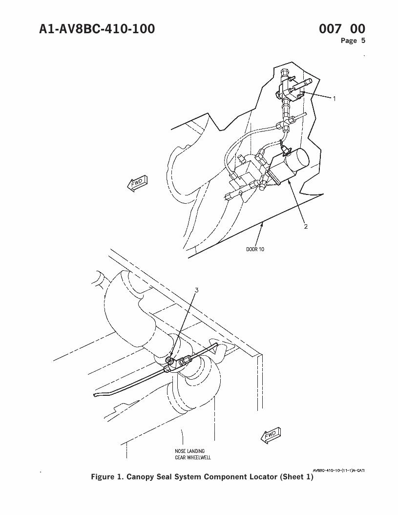
Figure 1. Canopy Seal System Component Locator (Sheet 1)
A1-AV8BC-410-100 007 00Page 5
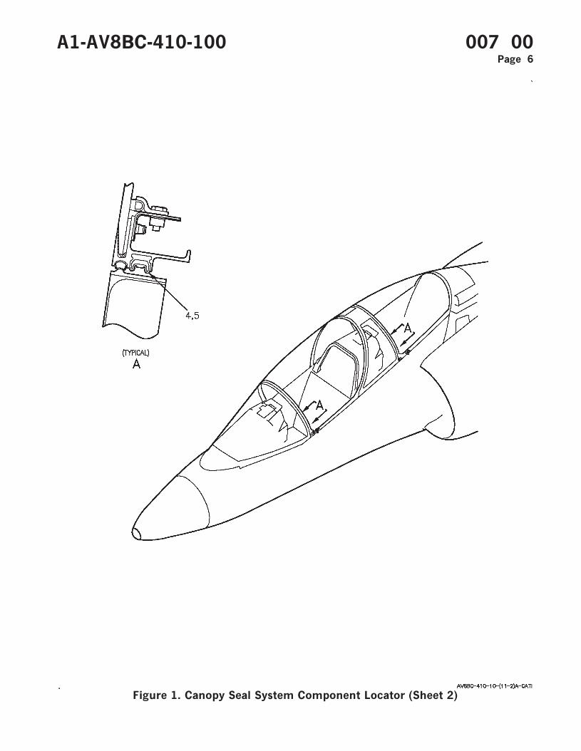
Figure 1. Canopy Seal System Component Locator (Sheet 2)
A1-AV8BC-410-100 007 00Page 6
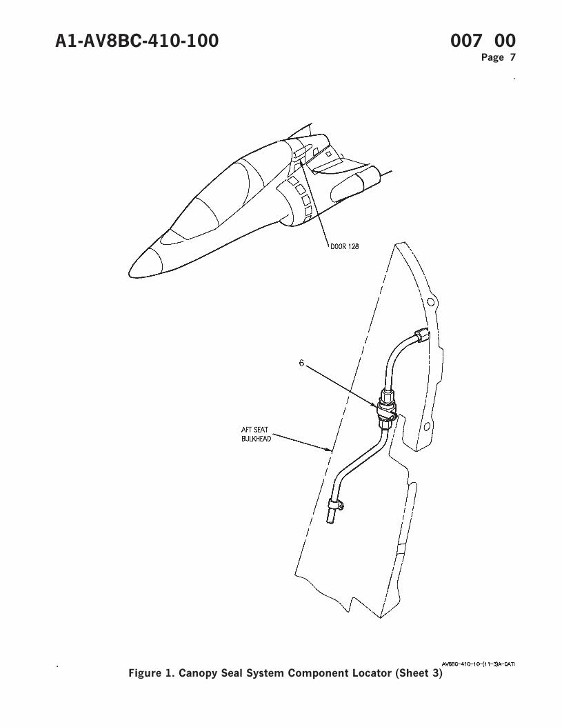
Figure 1. Canopy Seal System Component Locator (Sheet 3)
A1-AV8BC-410-100 007 00Page 7
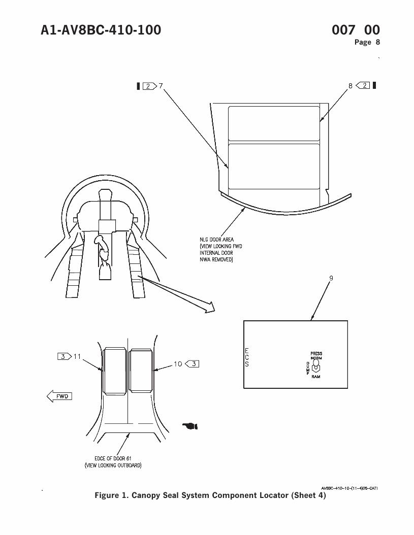
Figure 1. Canopy Seal System Component Locator (Sheet 4)
A1-AV8BC-410-100 007 00Page 8
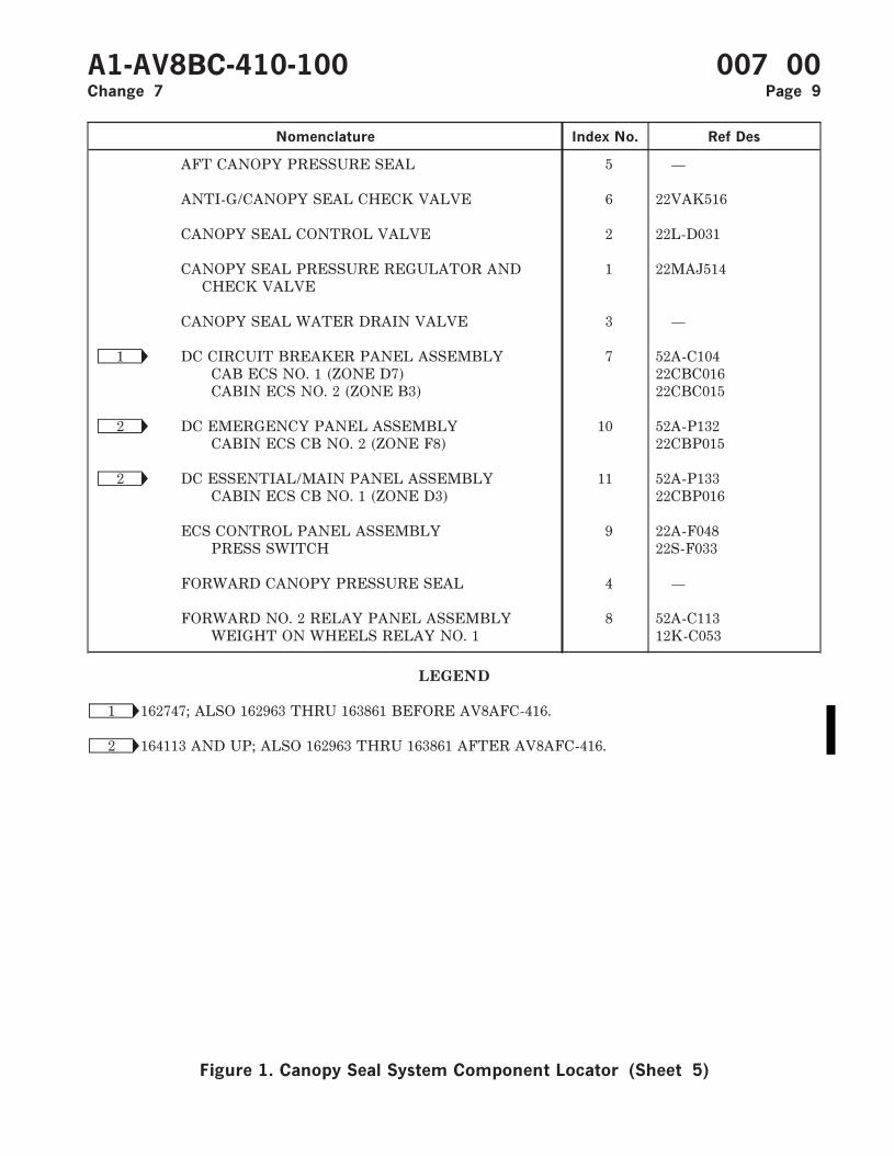
Nomenclature Index No. Ref Des
AFT CANOPY PRESSURE SEAL 5 —
ANTI-G/CANOPY SEAL CHECK VALVE 6 22VAK516
CANOPY SEAL CONTROL VALVE 2 22L-D031
CANOPY SEAL PRESSURE REGULATOR ANDCHECK VALVE
1 22MAJ514
CANOPY SEAL WATER DRAIN VALVE 3 —
Ñ1 DC CIRCUIT BREAKER PANEL ASSEMBLY 7 52A-C104CAB ECS NO. 1 (ZONE D7) 22CBC016CABIN ECS NO. 2 (ZONE B3) 22CBC015
Ñ2 DC EMERGENCY PANEL ASSEMBLY 10 52A-P132CABIN ECS CB NO. 2 (ZONE F8) 22CBP015
Ñ2 DC ESSENTIAL/MAIN PANEL ASSEMBLY 11 52A-P133CABIN ECS CB NO. 1 (ZONE D3) 22CBP016
ECS CONTROL PANEL ASSEMBLY 9 22A-F048PRESS SWITCH 22S-F033
FORWARD CANOPY PRESSURE SEAL 4 —
FORWARD NO. 2 RELAY PANEL ASSEMBLY 8 52A-C113WEIGHT ON WHEELS RELAY NO. 1 12K-C053
LEGEND
Ñ1 162747; ALSO 162963 THRU 163861 BEFORE AV8AFC-416.
Ñ2 164113 AND UP; ALSO 162963 THRU 163861 AFTER AV8AFC-416.
A1-AV8BC-410-100 007 00Change 7 Page 9
Figure 1. Canopy Seal System Component Locator (Sheet 5)

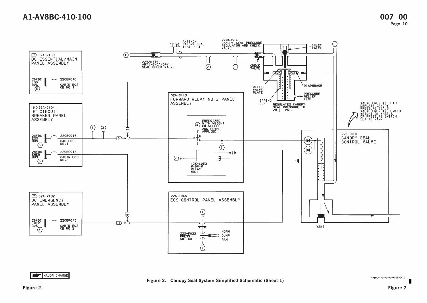
Figure 2. Canopy Seal System Simplified Schematic (Sheet 1)
A1-AV8BC-410-100 007 00Page 10
Figure 2. Figure 2.

Figure 2. Canopy Seal System Simplified Schematic (Sheet 2)
A1-AV8BC-410-100 007 00Change 7 Page 11/(12 blank)
Figure 2. Figure 2.
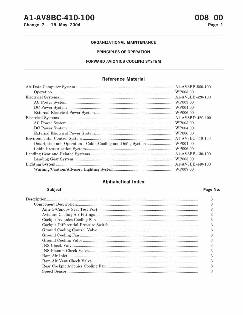
ORGANIZATIONAL MAINTENANCE
PRINCIPLES OF OPERATION
FORWARD AVIONICS COOLING SYSTEM
Reference Material
Air Data Computer System ............................................................................................. A1-AV8BB-560-100Operation.................................................................................................................... WP005 00
Electrical Systems............................................................................................................. A1-AV8BB-420-100AC Power System ..................................................................................................... WP003 00DC Power System ..................................................................................................... WP004 00External Electrical Power System.......................................................................... WP006 00
Electrical Systems............................................................................................................. A1-AV8BD-420-100AC Power System ..................................................................................................... WP003 00DC Power System ..................................................................................................... WP004 00External Electrical Power System.......................................................................... WP006 00
Environmental Control System ...................................................................................... A1-AV8BC-410-100Description and Operation - Cabin Cooling and Defog System ........................ WP004 00Cabin Pressurization System................................................................................... WP006 00
Landing Gear and Related Systems............................................................................... A1-AV8BB-130-100Landing Gear System............................................................................................... WP003 00
Lighting System ................................................................................................................ A1-AV8BB-440-100Warning/Caution/Advisory Lighting System........................................................ WP007 00
Alphabetical Index
Subject Page No.
Description ................................................................................................................................................... 3Component Description...................................................................................................................... 3
Anti-G/Canopy Seal Test Port.................................................................................................. 3Avionics Cooling Air Fittings .................................................................................................... 3Cockpit Avionics Cooling Fan ................................................................................................... 3Cockpit Differential Pressure Switch....................................................................................... 3Ground Cooling Control Valve.................................................................................................. 3Ground Cooling Fan ................................................................................................................... 3Ground Cooling Valve ................................................................................................................ 3INS Check Valve......................................................................................................................... 3INS Plenum Check Valve .......................................................................................................... 3Ram Air Inlet............................................................................................................................... 3Ram Air Vent Check Valve ....................................................................................................... 3Rear Cockpit Avionics Cooling Fan ......................................................................................... 3Speed Sensor................................................................................................................................ 3
A1-AV8BC-410-100 008 00Change 7 - 15 May 2004 Page 1
Alphabetical Index (Continued)
Subject Page No.
Related Systems .................................................................................................................................. 3AC Power System........................................................................................................................ 4Air Data Computer System ....................................................................................................... 4Cabin Cooling and Defog System ............................................................................................. 3DC Power System ....................................................................................................................... 4External Electrical Power System ............................................................................................ 4Landing Gear System ................................................................................................................. 4Warning/Caution/Advisory Lighting System.......................................................................... 4
System Controls and Indicators........................................................................................................ 4Cockpit Cool Cancel Relay ........................................................................................................ 4Cockpit Cooling Fan Relay........................................................................................................ 4Cockpit Fan Fail Relay .............................................................................................................. 4CS COOL Caution Lights .......................................................................................................... 5Fwd Fus Cooling Fan Control Relay........................................................................................ 5Fwd Fus Fan Fail Relay............................................................................................................. 5Gnd Pwr Fan Control Relay...................................................................................................... 5PRESS Switch ............................................................................................................................. 4Rear Cockpit Cool Cancel Relay............................................................................................... 5Rear Cockpit Cooling Fan Relay .............................................................................................. 5Rear Cockpit Fan Fail Relay..................................................................................................... 5
System Description ............................................................................................................................. 3Forward Avionics Cooling System Component Locator, Figure 1 ....................................................... 9Forward Avionics Cooling System Simplified Schematic-162747; ALSO 162963 THRU 163861
BEFORE AV8AFC-416, Figure 2......................................................................................................... 21Forward Avionics Cooling System Simplified Schematic-164113 AND UP; ALSO 162963
THRU 163861 AFTER AV8AFC-416, Figure 3 ................................................................................. 30Operation...................................................................................................................................................... 6
Component Operation ........................................................................................................................ 6Anti-G/Canopy Seal Test Port.................................................................................................. 6Avionics Cooling Air Fittings .................................................................................................... 6Cockpit Avionics Cooling Fan ................................................................................................... 6Cockpit Differential Pressure Switch....................................................................................... 7Ground Cooling Fan ................................................................................................................... 6Ground Cooling Control Valve.................................................................................................. 6Ground Cooling Valve ................................................................................................................ 7INS Check Valve......................................................................................................................... 7INS Plenum Check Valve .......................................................................................................... 7Ram Air Inlet............................................................................................................................... 7Ram Air Vent Check Valve ....................................................................................................... 7Rear Cockpit Avionics Cooling Fan ......................................................................................... 6Speed Sensor................................................................................................................................ 7
System Operation................................................................................................................................ 7Emergency Operation ................................................................................................................. 7Ground Operation ....................................................................................................................... 7Normal Operation ....................................................................................................................... 7
A1-AV8BC-410-100 008 00Change 7 Page 2
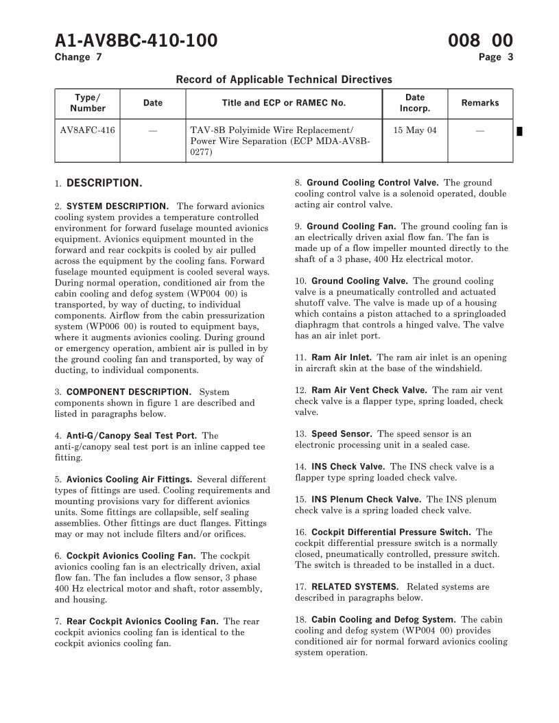
Record of Applicable Technical Directives
Type/
NumberDate Title and ECP or RAMEC No.
Date
Incorp.Remarks
AV8AFC-416 — TAV-8B Polyimide Wire Replacement/Power Wire Separation (ECP MDA-AV8B-0277)
15 May 04 —
1. DESCRIPTION.
2. SYSTEM DESCRIPTION. The forward avionicscooling system provides a temperature controlledenvironment for forward fuselage mounted avionicsequipment. Avionics equipment mounted in theforward and rear cockpits is cooled by air pulledacross the equipment by the cooling fans. Forwardfuselage mounted equipment is cooled several ways.During normal operation, conditioned air from thecabin cooling and defog system (WP004 00) istransported, by way of ducting, to individualcomponents. Airflow from the cabin pressurizationsystem (WP006 00) is routed to equipment bays,where it augments avionics cooling. During groundor emergency operation, ambient air is pulled in bythe ground cooling fan and transported, by way ofducting, to individual components.
3. COMPONENT DESCRIPTION. Systemcomponents shown in figure 1 are described andlisted in paragraphs below.
4. Anti-G/Canopy Seal Test Port. Theanti-g/canopy seal test port is an inline capped teefitting.
5. Avionics Cooling Air Fittings. Several differenttypes of fittings are used. Cooling requirements andmounting provisions vary for different avionicsunits. Some fittings are collapsible, self sealingassemblies. Other fittings are duct flanges. Fittingsmay or may not include filters and/or orifices.
6. Cockpit Avionics Cooling Fan. The cockpitavionics cooling fan is an electrically driven, axialflow fan. The fan includes a flow sensor, 3 phase400 Hz electrical motor and shaft, rotor assembly,and housing.
7. Rear Cockpit Avionics Cooling Fan. The rearcockpit avionics cooling fan is identical to thecockpit avionics cooling fan.
8. Ground Cooling Control Valve. The groundcooling control valve is a solenoid operated, doubleacting air control valve.
9. Ground Cooling Fan. The ground cooling fan isan electrically driven axial flow fan. The fan ismade up of a flow impeller mounted directly to theshaft of a 3 phase, 400 Hz electrical motor.
10. Ground Cooling Valve. The ground coolingvalve is a pneumatically controlled and actuatedshutoff valve. The valve is made up of a housingwhich contains a piston attached to a springloadeddiaphragm that controls a hinged valve. The valvehas an air inlet port.
11. Ram Air Inlet. The ram air inlet is an openingin aircraft skin at the base of the windshield.
12. Ram Air Vent Check Valve. The ram air ventcheck valve is a flapper type, spring loaded, checkvalve.
13. Speed Sensor. The speed sensor is anelectronic processing unit in a sealed case.
14. INS Check Valve. The INS check valve is aflapper type spring loaded check valve.
15. INS Plenum Check Valve. The INS plenumcheck valve is a spring loaded check valve.
16. Cockpit Differential Pressure Switch. Thecockpit differential pressure switch is a normallyclosed, pneumatically controlled, pressure switch.The switch is threaded to be installed in a duct.
17. RELATED SYSTEMS. Related systems aredescribed in paragraphs below.
18. Cabin Cooling and Defog System. The cabincooling and defog system (WP004 00) providesconditioned air for normal forward avionics coolingsystem operation.
A1-AV8BC-410-100 008 00Change 7 Page 3
19. AC Power System. The AC power system on162747; ALSO 162963 THRU 163861 BEFOREAV8AFC-416 (A1-AV8BB-420-100, WP003 00) or164113 AND UP; ALSO 162963 THRU 163861AFTER AV8AFC-416 (A1-AV8BD-420-100, WP00300) provides essential 115 vac power for the forwardavionics cooling system.
20. DC Power System. The DC power system on162747; ALSO 162963 THRU 163861 BEFOREAV8AFC-416 (A1-AV8BB-420-100, WP004 00) or164113 AND UP; ALSO 162963 THRU 163861AFTER AV8AFC-416 (A1-AV8BD- 420-100, WP00400) provides essential 28vdc power for the forwardavionics cooling system.
21. Warning/Caution/Advisory Lighting System.
The warning/caution/advisory lighting system(A1-AV8BB-440-100, WP007 00) provides visualindication of normal aircraft functions and systemmalfunctions affecting safety of flight operations.The warning/caution/advisory lighting systemincludes the annunciator light controller and thecaution/advisory indicator light assembly. Theannunciator light controller receives data fromvarious aircraft systems and provides logic to turnon and off warning/caution/advisory lights.
22. The annunciator light controller will turn onthe CS COOL caution lights and the MASTERCAUTION lights if either cockpit avionics coolingfan fails.
23. Landing Gear System. The landing gear system(A1-AV8BB-130-100, WP003 00) provides groundcontrol for the ground cooling fan and the groundcooling control valve through the weight on wheelsrelay no. 1.
24. External Electrical Power System. Theexternal electrical power system on 162747; ALSO162963 THRU 163861 BEFORE AV8AFC-416(A1-AV8BB-420-100, WP006 00) or 164113 ANDUP; ALSO 162963 THRU 163861 AFTERAV8AFC-416 (A1-AV8BD-420-100, WP006 00)provides electrical power for the forward avionicscooling system.
25. Air Data Computer System. The air datacomputer system (A1-AV8BB-560-100, WP005 00)provides an altitude signal to the forward avionicscooling system, through the 20K ft alt relay.
26. SYSTEM CONTROLS AND INDICATORS.
System controls and indicators are described in theparagraphs below.
27. PRESS Switch. The PRESS switch, located onthe ECS control panel assembly (WP004 00), is afour pole, lever lock, toggle switch. The switchprovides mode selection for the forward avionicscooling system. The switch has three positions;NORM, DUMP, and RAM. The switch is locked inall positions.
28. Setting the PRESS switch to NORM or RAM,allows cabin cooling and defog system (WP004 00)air to be tapped and transported by way of ductingto the avionics equipment.
29. Setting the PRESS switch to RAM, applies28vdc to energize the ground cooling control valveand the fwd fus cooling fan control relay. Theground cooling valve will open and the groundcooling fan will start to run.
30. Cockpit Cool Cancel Relay. The cockpit coolcancel relay, located on the forward relay no. 2panel assembly, is a 5 amperes, 2 pole, doublethrow, permanent magnet drive, armature relay.The relay is energized when the MASTERCAUTION light is reset.
31. When energized, the relay provides a ground toturn off the rear CS COOL caution light. A holdingcircuit keeps the relay energized until the cockpitavionics cooling fan resumes operation.
32. Cockpit Cooling Fan Relay. The cockpitcooling fan relay, located on the forward relay no. 1panel assembly, is a 5 amperes, 4 pole, doublethrow, permanent magnet drive, armature relay.The relay is energized when the cockpit avionicscooling fan thermal protector is closed.
33. When energized, the relay provides 115vacpower to the cockpit avionics cooling fan. Whendeenergized, the relay removes 115vac power fromthe fan.
34. Cockpit Fan Fail Relay. The cockpit fan failrelay, located on the forward relay no. 2 panelassembly, is a 5 amperes, 2 pole, double throw,permanent magnet drive, armature relay. The relayis energized when the cockpit avionics cooling fanspeed is approximately 60 percent rpm or greater.
A1-AV8BC-410-100 008 00Change 7 Page 4
35. When energized, the relay disables the CSCOOL caution lights by providing a ground to thewarning/caution/advisory lighting system.
36. When deenergized, the relay;
a. Removes a ground to thewarning/caution/advisory lighting system to enablethe CS COOL caution lights.
b. Provides a ground to the rear cockpit coolingcancel relay holding circuit.
37. Fwd Fus Cooling Fan Control Relay. The fwdfus cooling fan control relay, located on the forwardrelay no. 1 panel assembly, is a four pole, doublethrow, 5 amperes, permanent magnet drive,armature relay.
38. The relay is energized with aircraft weight onwheels, or aircraft altitude less than 20,000 feet, orcabin pressure less than 2.00±0.5 psi, or PRESSswitch set to RAM. With the relay energized,essential 115 vac power is applied to three phases ofthe ground cooling fan motor. With the relaydeenergized, essential 115 vac power to the fanmotor is lost.
39. Fwd Fus Fan Fail Relay. The fwd fus fan failrelay, located on the forward relay no. 2 panelassembly, is a 2 pole, double throw, 5 amperes,permanent magnet drive, armature relay. The relayis energized when the speed sensor senses groundcooling fan speed of approximately 60 percent rpmor less.
40. With the relay energized, 28vdc is removed todeenergize the fwd fus cooling fan control relay.With the relay deenergized, 28vdc is applied toenergize the fwd fus cooling fan control relay.
41. Gnd Pwr Fan Control Relay. The gnd pwr fancontrol relay, located on the forward relay no. 1panel assembly, is a 5 amperes, double pole, doublethrow permanent magnet drive, armature relay. Therelay is energized when the rear cockpit avionicscooling fan speed is approximately 60 percent rpmor greater.
42. With the relay energized, a ground signal isprovided to the COCKPIT switch of the externalelectrical power system.
43. Rear Cockpit Cool Cancel Relay. The rearcockpit cool cancel relay, located on the forward
relay no. 2 panel assembly, is a 5 amperes, 2 pole,double throw, permanent magnet drive, armaturerelay. The relay is energized when the MASTERCAUTION light is reset.
44. When energized, the relay provides a ground toturn off the CS COOL caution light. A holdingcircuit keeps the relay energized until the rearcockpit avionics cooling fan resumes operation.
45. Rear Cockpit Cooling Fan Relay. The rearcockpit cooling fan relay, located on the forwardrelay no. 1 panel assembly, is a 5 amperes, 4 pole,double throw, permanent magnet drive, armaturerelay. The relay is energized with the rear cockpitavionics cooling fan thermal protector closed.
46. With the relay energized, 115vac is applied tothe rear cockpit avionics cooling fan. With the relaydeenergized, 115vac power is removed from the rearcockpit avionics cooling fan.
47. Rear Cockpit Fan Fail Relay. The rear cockpitfan fail relay, located on the forward relay no. 2panel assembly, is a 5 amperes, 2 pole, doublethrow, permanent magnet drive, armature relay.The relay is energized when the rear cockpitavionics cooling fan is operating at 60 percent rpmor greater.
48. When energized, the relay disables the rear CSCOOL caution light by providing a ground to thewarning/caution/advisory lighting system.
49. When deenergized, the relay;
a. Removes a ground to thewarning/caution/advisory lighting system to enablethe CS COOL caution lights.
b. Provides a ground to the cockpit coolingcancel relay holding circuit.
50. CS COOL Caution Lights. The CS COOLcaution lights are located on the caution/advisoryindicator light assembly and the rearcaution/advisory indicator light assembly.
51. The CS COOL caution lights are controlled bythe cockpit avionics cooling fan, rear cockpitavionics cooling fan, cockpit fan fail relay, rearcockpit fan fail relay, cockpit cool cancel relay, andrear cockpit cool cancel relay through thewarning/caution/advisory lighting system.
52. Both CS COOL lights will come on and flash ifthe cockpit avionics cooling fan or the rear cockpit
A1-AV8BC-410-100 008 00Change 6 Page 5

avionics cooling fan fail. Resetting the mastercaution will cause the CS COOL light in theaffected cockpit to come on steady, the light in theunaffected cockpit will go off.
53. OPERATION.
54. COMPONENT OPERATION.
55. Anti-G/Canopy Seal Test Port. Theanti-g/canopy seal test port is located in theforward end of the nose landing gear wheelwell. Thetest port allows a ground air source to be used totest the operation of the ground cooling controlvalve and ground cooling valve. With either groundair source or normal air source used, the valvesoperate the same.
56. Avionics Cooling Air Fittings. Avionics coolingair fittings, located on equipment mounting racks inthe cockpit, rear cockpit, and door 125L, providethe cooling system interface between rack mountedequipment and equipment rack. When a unit isinstalled on the equipment rack, it makes contactwith a cooling air fitting. The fitting makes a sealbetween the unit and the rack, allowing cooling airto flow through the unit. Some fittings contact theunit on the back and some contact on the bottom,depending on unit mounting. The different types offittings used are required for the different coolingrequirements of each unit.
57. Cockpit Avionics Cooling Fan. The cockpitavionics cooling fan, located in the cockpit underthe main instrument panel, pulls cabin air throughcockpit mounted avionics equipment. The fanoperates when the cockpit cooling fan relay isenergized.
58. The rotor assembly is mounted on the end ofthe shaft, which is driven by the motor. Thespinning rotor assembly pulls cockpit air across thecockpit mounted avionics equipment. The fanexhaust air is directed to the rudder pedal area.
59. The flow sensor is made up of electrical circuits,an open ended tube and two temperature sensingdevices. The tube faces the airstream and directs asmall amount of air over the temperature sensingdevices. The temperature sensing devices producean output voltage proportional to their temperature.One temperature sensing device is heated at aconstant rate. Its voltage output and temperatureare proportional to the amount of cooling airpassing over it, which changes with fan airflow.
Electrical circuits in the flow sensor comparevoltage outputs of the two temperature sensingdevices. If the voltage difference exceeds apredetermined limit, which corresponds toapproximately less than 60 percent of normal fanspeed, the CS COOL caution lights are enabled andavionics ground power application is inhibited.
60. The fan has a built in thermal protector. Thethermal protector is normally closed and will openwhen the fan motor overheats. Opening the thermalprotector will deenergize the cockpit cooling fanrelay and remove essential 115vac power from thefan motor. The thermal protector will close whenthe fan motor cools.
61. Rear Cockpit Avionics Cooling Fan. The rearcockpit avionics cooling fan, located in the rearcockpit under the main instrument panel, pullscabin air through rear cockpit mounted avionicsequipment. The fan operation is identical to thecockpit avionics cooling fan.
62. Ground Cooling Control Valve. The groundcooling control valve is located in door 121. Whendeenergized by weight off wheels or the PRESSswitch in other than RAM, the valve allows air fromthe cabin cooling and defog system (WP004 00) toflow through and hold the ground cooling valveclosed. With the valve energized by weight onwheels or the PRESS switch in RAM, air is ventedto atmosphere and the ground cooling valve opensby spring tension.
63. Ground Cooling Fan. The ground cooling fan islocated in door 121. The motor and impeller areenclosed in a housing which has guide vanes built inon the outlet side of the impeller. The guide vanesstraighten the airflow before discharge from the fan.The motor includes an electrical sensing unit andoverheat protection devices. The electrical sensingunit provides an electrical signal to the speed sensorbased on fan speed. The overheat protection deviceswill automatically stop the fan if an overheatoccurs. When the overheat condition no longerexists, the fan will resume normal operation. Thefan motor is cooled by its own airflow.
64. With the fan operating, cooling air is pulled inthrough the ground cooling valve. The cooling air isgiven a high velocity by the fan impeller and istransported by way of ducting to forward fuselagemounted avionics equipment. The fan will operatewhen electrical power is applied and weight is on
A1-AV8BC-410-100 008 00Change 6 Page 6

wheels, or aircraft altitude less than 20,000 feet, orcabin pressure less than 2.00±0.5 psi, or PRESSswitch set to RAM.
65. Ground Cooling Valve. The ground coolingvalve is located in the ram air inlet. When airpressure tapped from the cabin cooling and defogsystem (WP004 00) is applied to the valve inletport through the ground cooling control valve, thespring loaded diaphragm is compressed, the pistonmoves and closes the valve. When air pressure isnot applied or is lost, the spring loaded diaphragmmoves the piston and opens the valve. The valve,with the ground cooling fan, allows ambient air toflow and cool forward fuselage mounted avionicsequipment for ground operation or inflight if acooling system failure occurs.
66. Ram Air Inlet. The ram air inlet, located on thewindshield forward fairing, allows ram or ambientair to enter the forward avionics cooling systemduring ground or emergency operation. The inletfaces forward so aircraft forward motion will forceair into the inlet. During ground operation, theground cooling valve will open and allow ambientair to be pulled in the inlet. During inflightemergency operation, ram air flows to equipmentcooling system and to each cockpit.
67. Ram Air Vent Check Valve. The ram air ventcheck valve is located in door 10. The check valveprevents loss of ambient air through the nose coneduring ground cooling fan operation. The valveflappers are spring loaded closed and allow airflowin one direction only.
68. Speed Sensor. The speed sensor is located indoor 121. The speed sensor receives an electricalsignal from the ground cooling fan electronicsensing unit. The signal is proportional to fanrotational speed. If the signal received by the speedsensor is within a predetermined limit, the speedsensor will complete an electrical circuit and allowavionics ground power to be applied. If the signal isout of limits, the speed sensor will inhibitapplication of avionics ground power.
69. INS Check Valve. The INS check valve islocated in the equipment cooling distribution ductbetween the Inertial Navigation UnitCN-1561/ASN-130A or CN-1649/ASN-139 coolingplenum assembly and the ground cooling fan. Thecheck valve prevents the loss of cockpit air throughthe non-operating ground cooling fan. The valve
flappers are spring loaded closed and allow airflowin one direction only.
70. INS Plenum Check Valve. The INS plenumcheck valve is located in the distribution ductbetween the air communication duct and theInertial Navigation Unit CN-1516/ASN-130A orCN-1649/ASN-139 cooling plenum assembly. Thecheck valve prevents loss of equipment cooling airthrough the cockpit and rear cockpit during groundoperation. The valve flappers are spring loadedclosed and allow airflow in one direction only.
71. Cockpit Differential Pressure Switch. Thecockpit differential pressure switch is located in theair communication duct in door 10. The switchsenses cabin pressure. When cabin pressure is lessthan 2.0±0.5 psid, the switch is closed and applies28vdc power to energize the fwd fus cooling fancontrol relay. When cabin pressure is greater than2.0±0.5 psid, the switch opens and removes 28vdcpower to deenergize the fwd fus cooling fan controlrelay.
72. SYSTEM OPERATION.
73. Normal Operation. The forward avionicscooling system (figure 2) provides conditioned airfor cooling avionics equipment. Conditioned air istapped off the cabin cooling and defog system(WP004 00). The conditioned air is transported byway of ducting to forward fuselage mountedavionics equipment. Check valves in the distributionducting prevent loss of airflow through the ram airinlet and ground cooling fan. Cockpit and rearcockpit mounted avionics equipment is cooled bycockpit avionics cooling fans. Cabin air is pulledacross the equipment by the fans. Caution lightswarn the crewmembers of a fan malfunction.
74. The ground cooling fan operates with aircraftweight on wheels, or altitude less than 20,000 feet,or cabin pressure less than 2.0±0.5 psig.
75. Ground Operation. During ground operation,the ground cooling fan pulls ambient air in throughthe open ground cooling valve. The cooling air istransported by way of ducting to the avionicsequipment. A check valve prevents loss of airflowthrough the cabin cooling and defog system(WP004 00).
76. Emergency Operation. In flight during aforward avionics cooling system failure, the pilot
A1-AV8BC-410-100 008 00Change 6 Page 7
can open the ground cooling valve by setting thePRESS switch to RAM. Ram air will flow toforward fuselage mounted avionics equipment by
way of ducting for emergency cooling. Ram air alsoflows to the cockpit and rear cockpit.
A1-AV8BC-410-100 008 00Change 6 Page 8
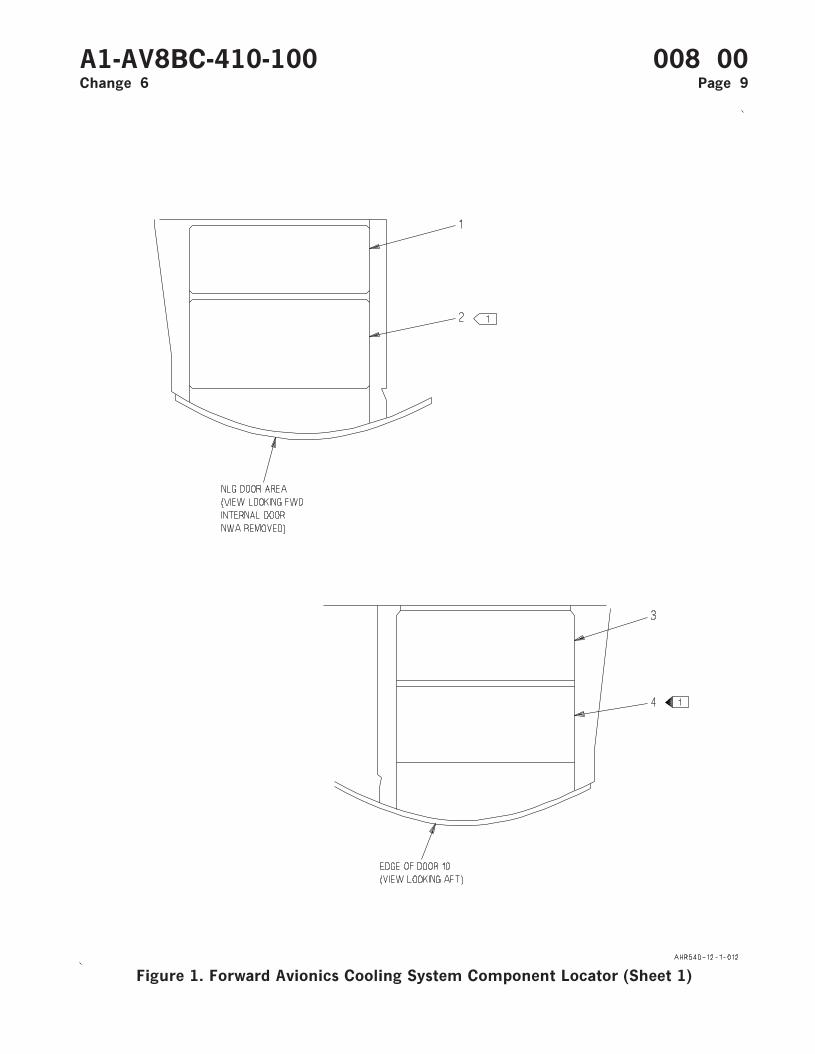
Figure 1. Forward Avionics Cooling System Component Locator (Sheet 1)
A1-AV8BC-410-100 008 00Change 6 Page 9
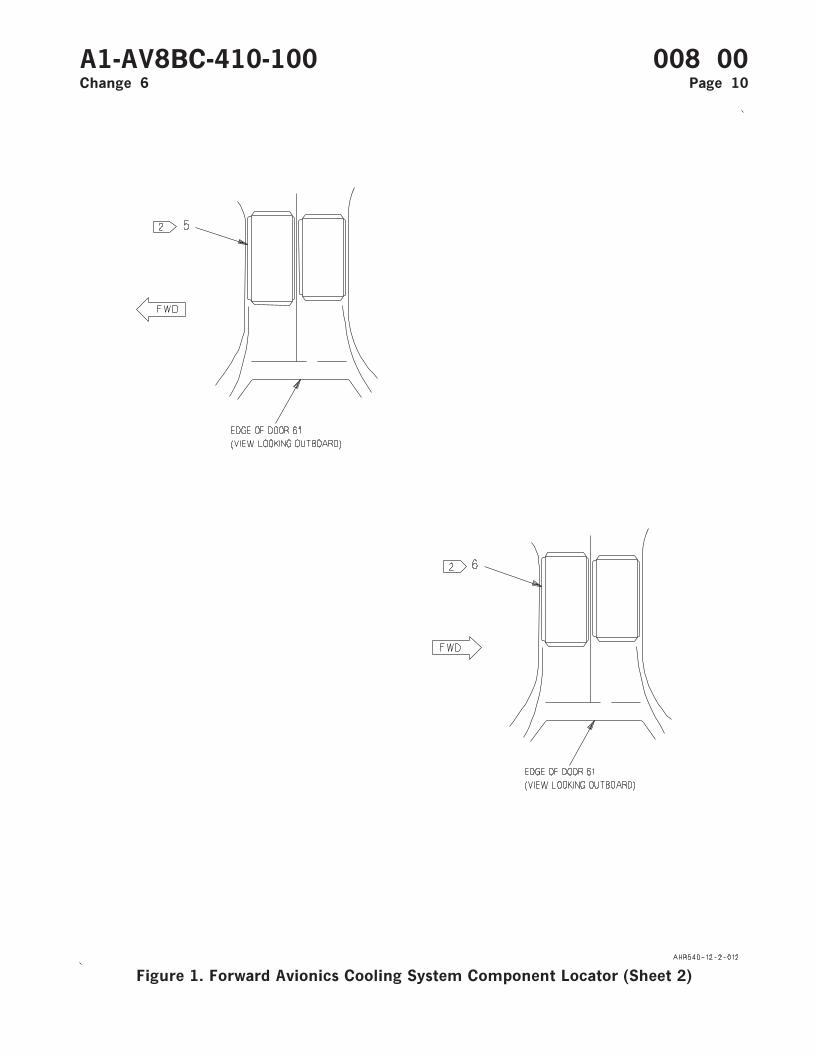
Figure 1. Forward Avionics Cooling System Component Locator (Sheet 2)
A1-AV8BC-410-100 008 00Change 6 Page 10
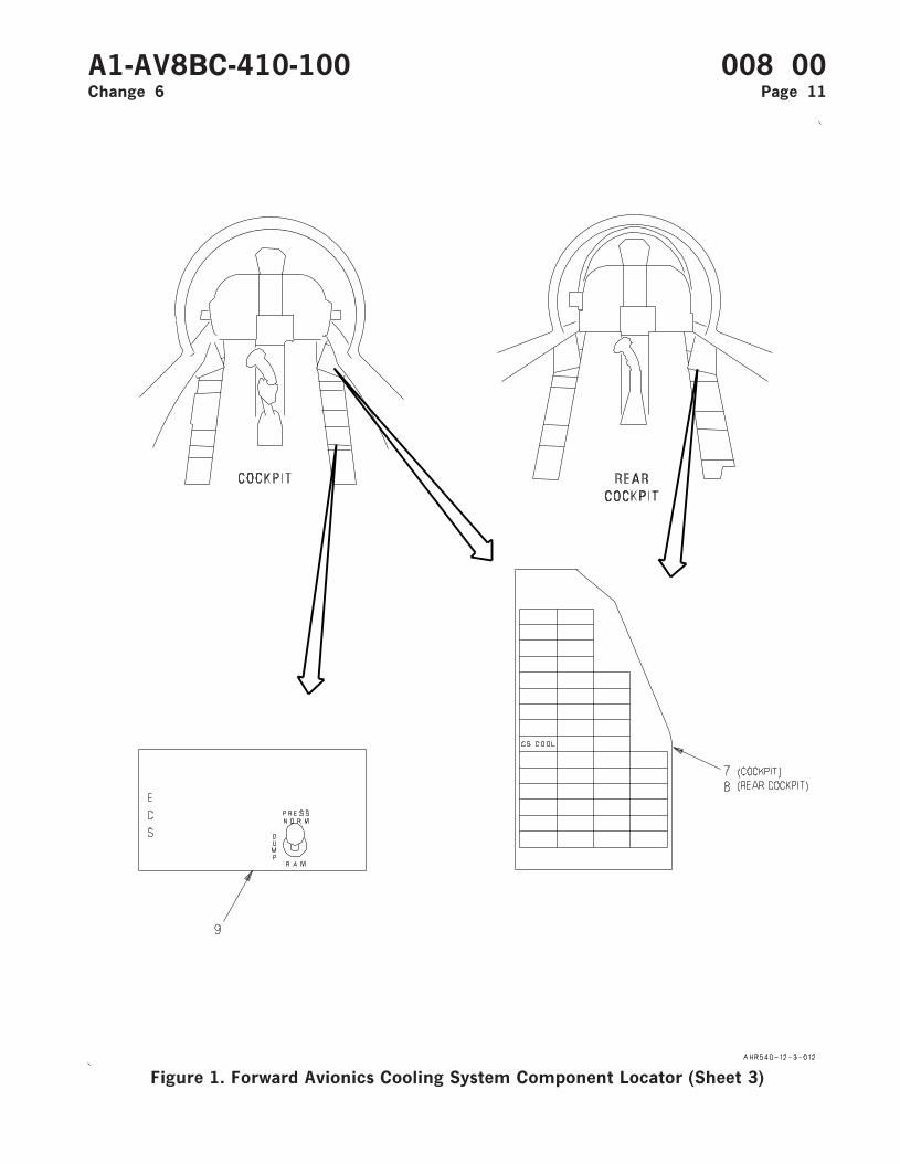
Figure 1. Forward Avionics Cooling System Component Locator (Sheet 3)
A1-AV8BC-410-100 008 00Change 6 Page 11

Figure 1. Forward Avionics Cooling System Component Locator (Sheet 4)
A1-AV8BC-410-100 008 00Change 6 Page 12
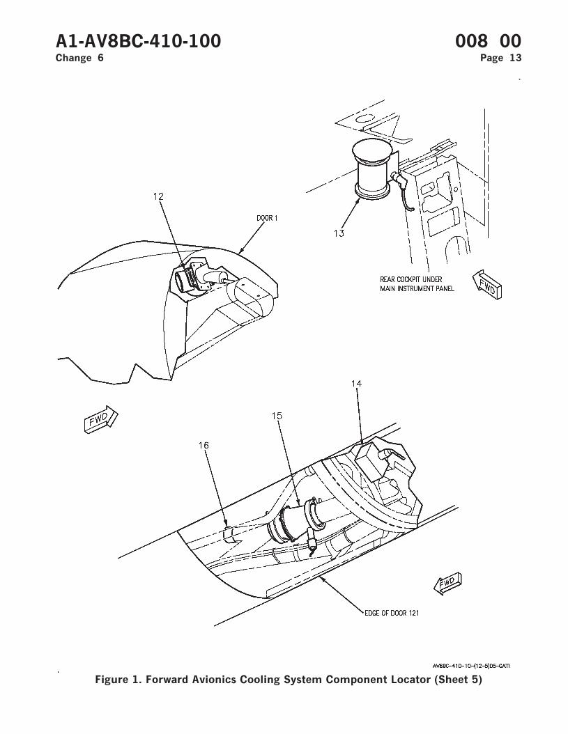
Figure 1. Forward Avionics Cooling System Component Locator (Sheet 5)
A1-AV8BC-410-100 008 00Change 6 Page 13
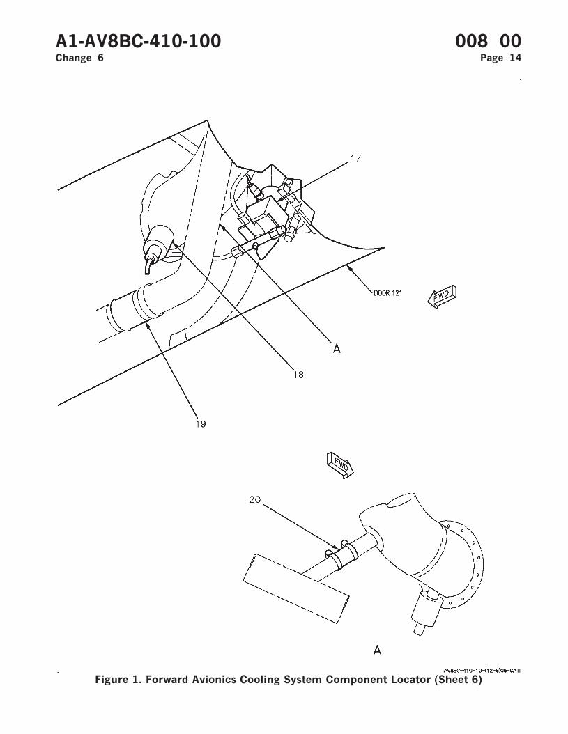
Figure 1. Forward Avionics Cooling System Component Locator (Sheet 6)
A1-AV8BC-410-100 008 00Change 6 Page 14
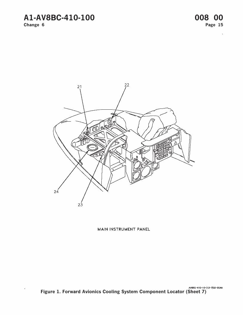
Figure 1. Forward Avionics Cooling System Component Locator (Sheet 7)
A1-AV8BC-410-100 008 00Change 6 Page 15
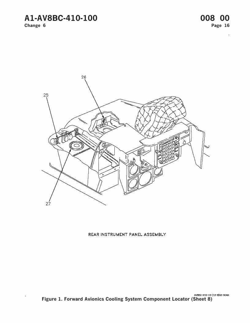
Figure 1. Forward Avionics Cooling System Component Locator (Sheet 8)
A1-AV8BC-410-100 008 00Change 6 Page 16
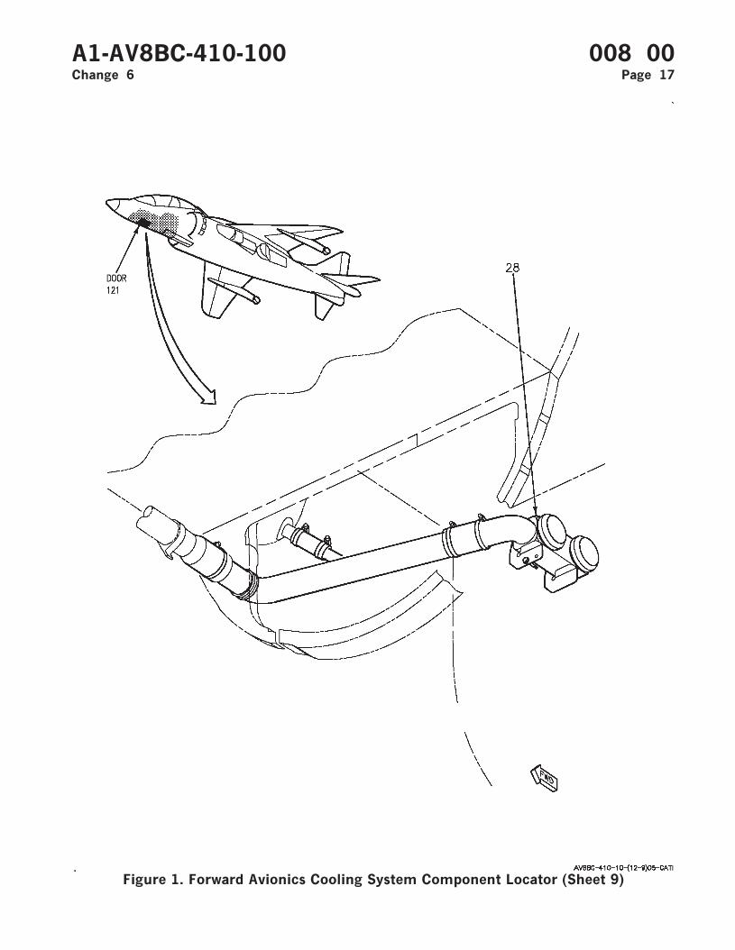
Figure 1. Forward Avionics Cooling System Component Locator (Sheet 9)
A1-AV8BC-410-100 008 00Change 6 Page 17
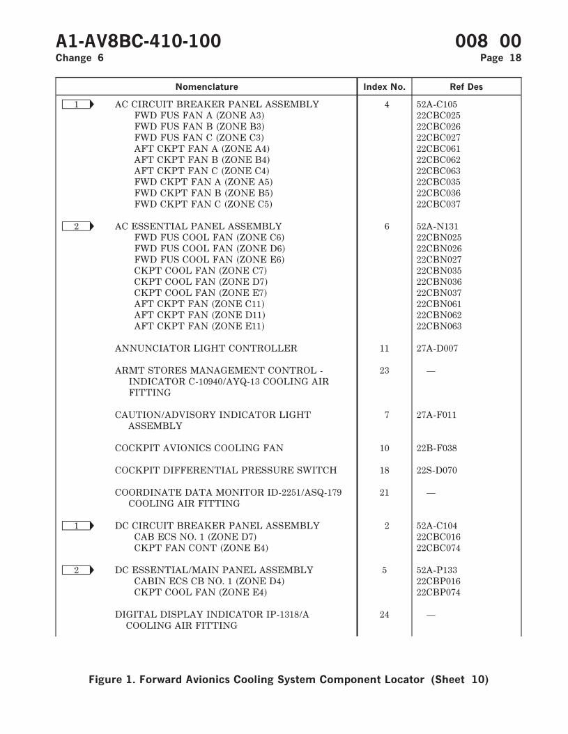
Nomenclature Index No. Ref Des
Ñ1 AC CIRCUIT BREAKER PANEL ASSEMBLY 4 52A-C105FWD FUS FAN A (ZONE A3) 22CBC025FWD FUS FAN B (ZONE B3) 22CBC026FWD FUS FAN C (ZONE C3) 22CBC027AFT CKPT FAN A (ZONE A4) 22CBC061AFT CKPT FAN B (ZONE B4) 22CBC062AFT CKPT FAN C (ZONE C4) 22CBC063FWD CKPT FAN A (ZONE A5) 22CBC035FWD CKPT FAN B (ZONE B5) 22CBC036FWD CKPT FAN C (ZONE C5) 22CBC037
Ñ2 AC ESSENTIAL PANEL ASSEMBLY 6 52A-N131FWD FUS COOL FAN (ZONE C6) 22CBN025FWD FUS COOL FAN (ZONE D6) 22CBN026FWD FUS COOL FAN (ZONE E6) 22CBN027CKPT COOL FAN (ZONE C7) 22CBN035CKPT COOL FAN (ZONE D7) 22CBN036CKPT COOL FAN (ZONE E7) 22CBN037AFT CKPT FAN (ZONE C11) 22CBN061AFT CKPT FAN (ZONE D11) 22CBN062AFT CKPT FAN (ZONE E11) 22CBN063
ANNUNCIATOR LIGHT CONTROLLER 11 27A-D007
ARMT STORES MANAGEMENT CONTROL -INDICATOR C-10940/AYQ-13 COOLING AIRFITTING
23 —
CAUTION/ADVISORY INDICATOR LIGHTASSEMBLY
7 27A-F011
COCKPIT AVIONICS COOLING FAN 10 22B-F038
COCKPIT DIFFERENTIAL PRESSURE SWITCH 18 22S-D070
COORDINATE DATA MONITOR ID-2251/ASQ-179COOLING AIR FITTING
21 —
Ñ1 DC CIRCUIT BREAKER PANEL ASSEMBLY 2 52A-C104CAB ECS NO. 1 (ZONE D7) 22CBC016CKPT FAN CONT (ZONE E4) 22CBC074
Ñ2 DC ESSENTIAL/MAIN PANEL ASSEMBLY 5 52A-P133CABIN ECS CB NO. 1 (ZONE D4) 22CBP016CKPT COOL FAN (ZONE E4) 22CBP074
DIGITAL DISPLAY INDICATOR IP-1318/ACOOLING AIR FITTING
24 —
A1-AV8BC-410-100 008 00Change 6 Page 18
Figure 1. Forward Avionics Cooling System Component Locator (Sheet 10)
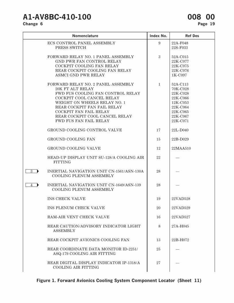
Nomenclature Index No. Ref Des
ECS CONTROL PANEL ASSEMBLY 9 22A-F048PRESS SWITCH 22S-F033
FORWARD RELAY NO. 1 PANEL ASSEMBLY 3 52A-C015GND PWR FAN CONTROL RELAY 22K-C077COCKPIT COOLING FAN RELAY 22K-C075REAR COCKPIT COOLING FAN RELAY 22K-C076ASMCI GND PWR RELAY 1K-C097
FORWARD RELAY NO. 2 PANEL ASSEMBLY 1 52A-C11320K FT ALT RELAY 70K-C028FWD FUS COOLING FAN CONTROL RELAY 22K-C028COCKPIT COOL CANCEL RELAY 22K-C066WEIGHT ON WHEELS RELAY NO. 1 12K-C053REAR COCKPIT FAN FAIL RELAY 22K-C064COCKPIT FAN FAIL RELAY 22K-C065REAR COCKPIT COOL CANCEL RELAY 22K-C067FWD FUS FAN FAIL RELAY 22K-C071
GROUND COOLING CONTROL VALVE 17 22L-D040
GROUND COOLING FAN 15 22B-D029
GROUND COOLING VALVE 12 22MAA510
HEAD-UP DISPLAY UNIT SU-128/A COOLING AIRFITTING
22 —
Ñ3 INERTIAL NAVIGATION UNIT CN-1561/ASN-130ACOOLING PLENUM ASSEMBLY
28 —
Ñ4 INERTIAL NAVIGATION UNIT CN-1649/ASN-139COOLING PLENUM ASSEMBLY
28 —
INS CHECK VALVE 19 22VAD528
INS PLENUM CHECK VALVE 20 22VAD529
RAM-AIR VENT CHECK VALVE 16 22VAD527
REAR CAUTION/ADVISORY INDICATOR LIGHTASSEMBLY
8 27A-H045
REAR COCKPIT AVIONICS COOLING FAN 13 22B-H072
REAR COORDINATE DATA MONITOR ID-2251/ASQ-179 COOLING AIR FITTING
25 —
REAR DIGITAL DISPLAY INDICATOR IP-1318/ACOOLING AIR FITTING
27 —
A1-AV8BC-410-100 008 00Change 6 Page 19
Figure 1. Forward Avionics Cooling System Component Locator (Sheet 11)
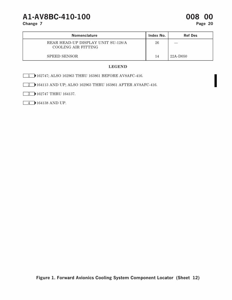
Nomenclature Index No. Ref Des
REAR HEAD-UP DISPLAY UNIT SU-128/ACOOLING AIR FITTING
26 —
SPEED SENSOR 14 22A-D050
LEGEND
Ñ1 162747; ALSO 162963 THRU 163861 BEFORE AV8AFC-416.
Ñ2 164113 AND UP; ALSO 162963 THRU 163861 AFTER AV8AFC-416.
Ñ3 162747 THRU 164137.
Ñ4 164138 AND UP.
A1-AV8BC-410-100 008 00Change 7 Page 20
Figure 1. Forward Avionics Cooling System Component Locator (Sheet 12)

Figure 2. Forward Avionics Cooling System Simplified Schematic-162747; ALSO 162963THRU 163861 BEFORE AV8AFC-416 (Sheet 1)
A1-AV8BC-410-100 008 00Change 7 Page 21
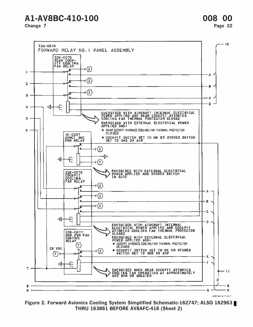
Figure 2. Forward Avionics Cooling System Simplified Schematic-162747; ALSO 162963THRU 163861 BEFORE AV8AFC-416 (Sheet 2)
A1-AV8BC-410-100 008 00Change 7 Page 22
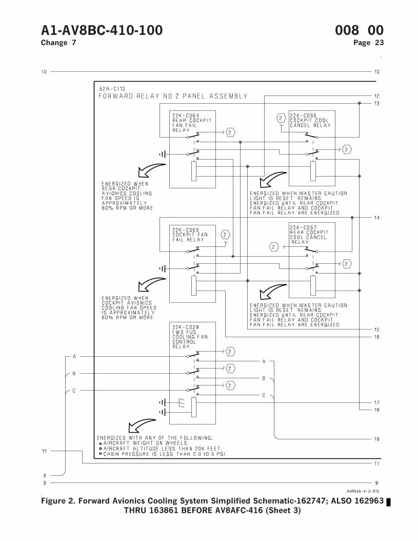
Figure 2. Forward Avionics Cooling System Simplified Schematic-162747; ALSO 162963THRU 163861 BEFORE AV8AFC-416 (Sheet 3)
A1-AV8BC-410-100 008 00Change 7 Page 23
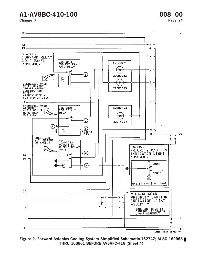
Figure 2. Forward Avionics Cooling System Simplified Schematic-162747; ALSO 162963THRU 163861 BEFORE AV8AFC-416 (Sheet 4)
A1-AV8BC-410-100 008 00Change 7 Page 24
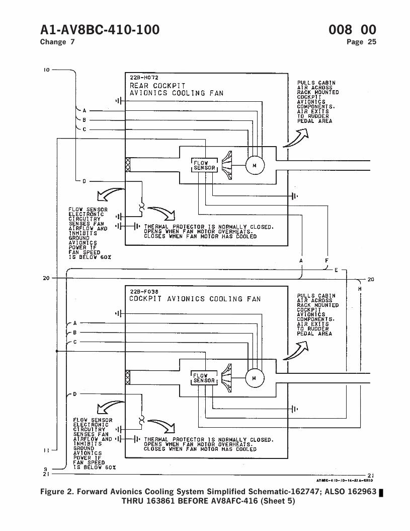
Figure 2. Forward Avionics Cooling System Simplified Schematic-162747; ALSO 162963THRU 163861 BEFORE AV8AFC-416 (Sheet 5)
A1-AV8BC-410-100 008 00Change 7 Page 25
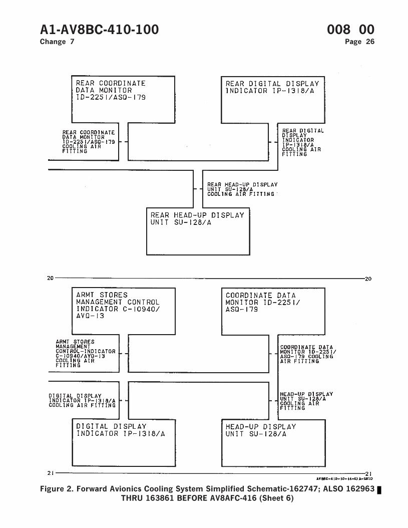
Figure 2. Forward Avionics Cooling System Simplified Schematic-162747; ALSO 162963THRU 163861 BEFORE AV8AFC-416 (Sheet 6)
A1-AV8BC-410-100 008 00Change 7 Page 26
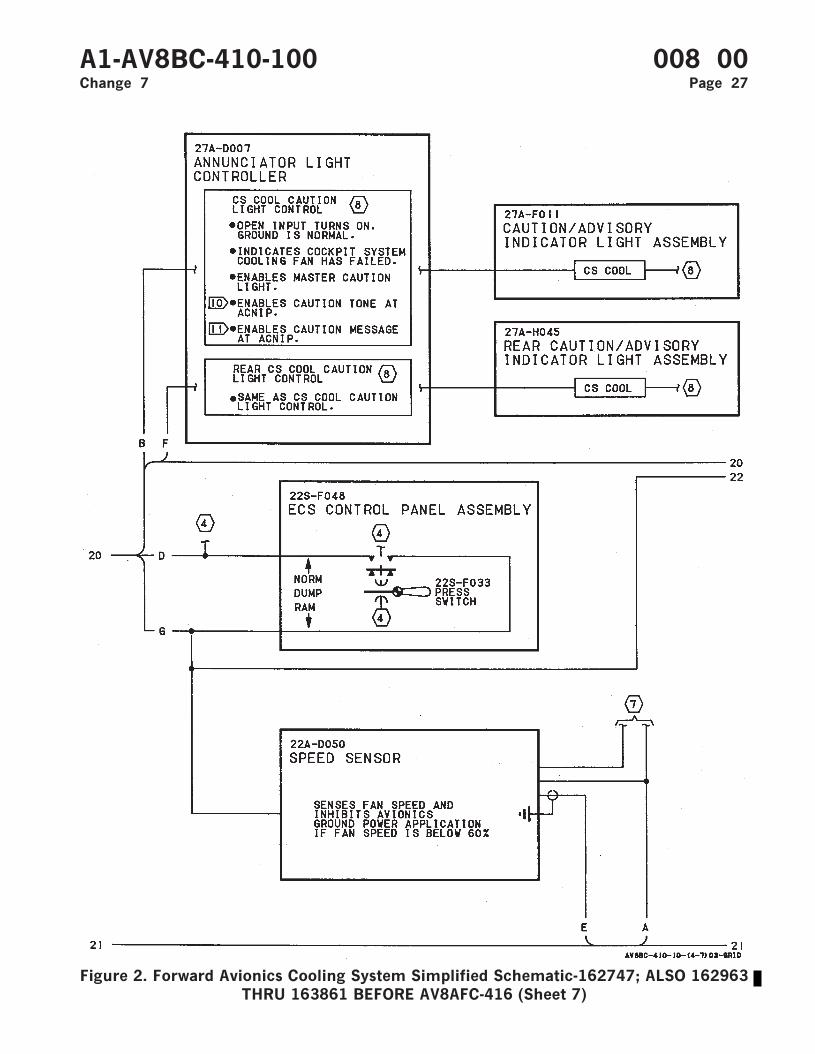
Figure 2. Forward Avionics Cooling System Simplified Schematic-162747; ALSO 162963THRU 163861 BEFORE AV8AFC-416 (Sheet 7)
A1-AV8BC-410-100 008 00Change 7 Page 27
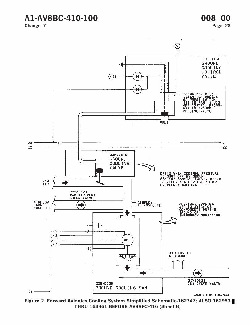
Figure 2. Forward Avionics Cooling System Simplified Schematic-162747; ALSO 162963THRU 163861 BEFORE AV8AFC-416 (Sheet 8)
A1-AV8BC-410-100 008 00Change 7 Page 28
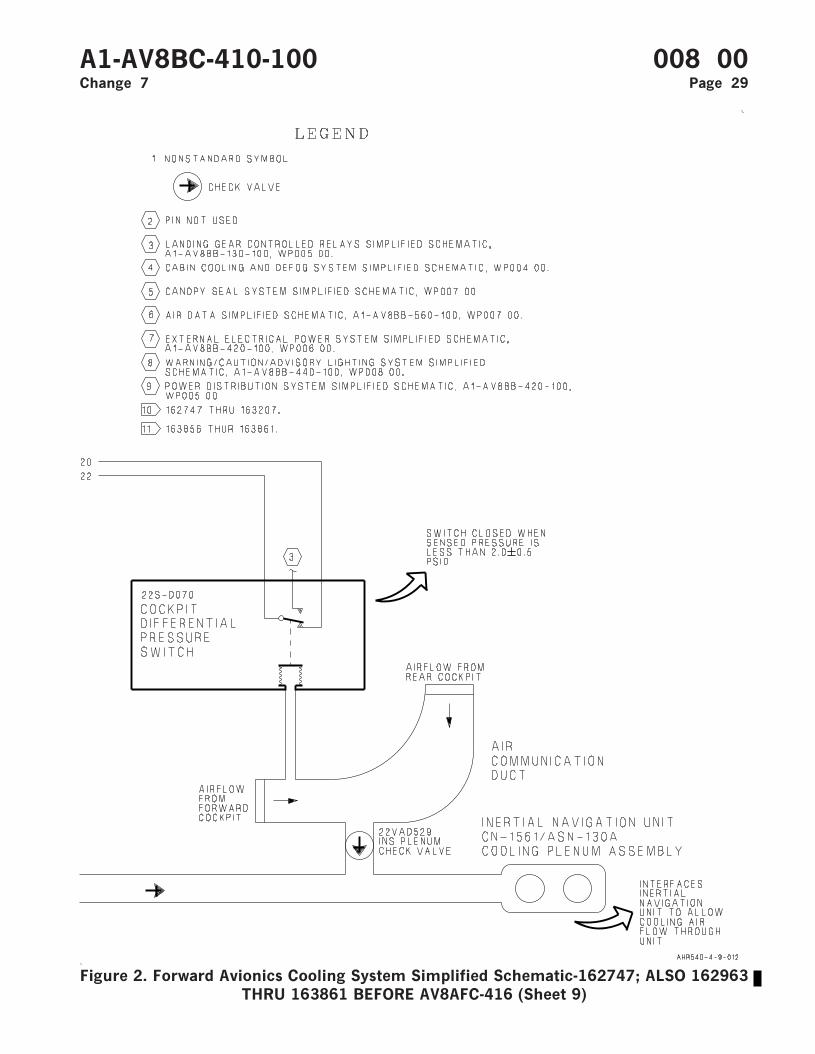
Figure 2. Forward Avionics Cooling System Simplified Schematic-162747; ALSO 162963THRU 163861 BEFORE AV8AFC-416 (Sheet 9)
A1-AV8BC-410-100 008 00Change 7 Page 29

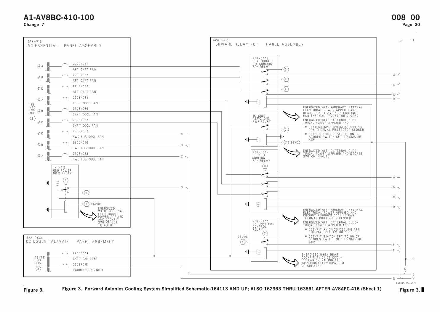
Figure 3. Forward Avionics Cooling System Simplified Schematic-164113 AND UP; ALSO 162963 THRU 163861 AFTER AV8AFC-416 (Sheet 1)
A1-AV8BC-410-100 008 00Change 7 Page 30
Figure 3. Figure 3.
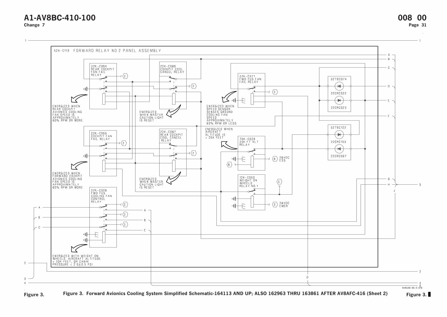
Figure 3. Forward Avionics Cooling System Simplified Schematic-164113 AND UP; ALSO 162963 THRU 163861 AFTER AV8AFC-416 (Sheet 2)
A1-AV8BC-410-100 008 00Change 7 Page 31
Figure 3. Figure 3.
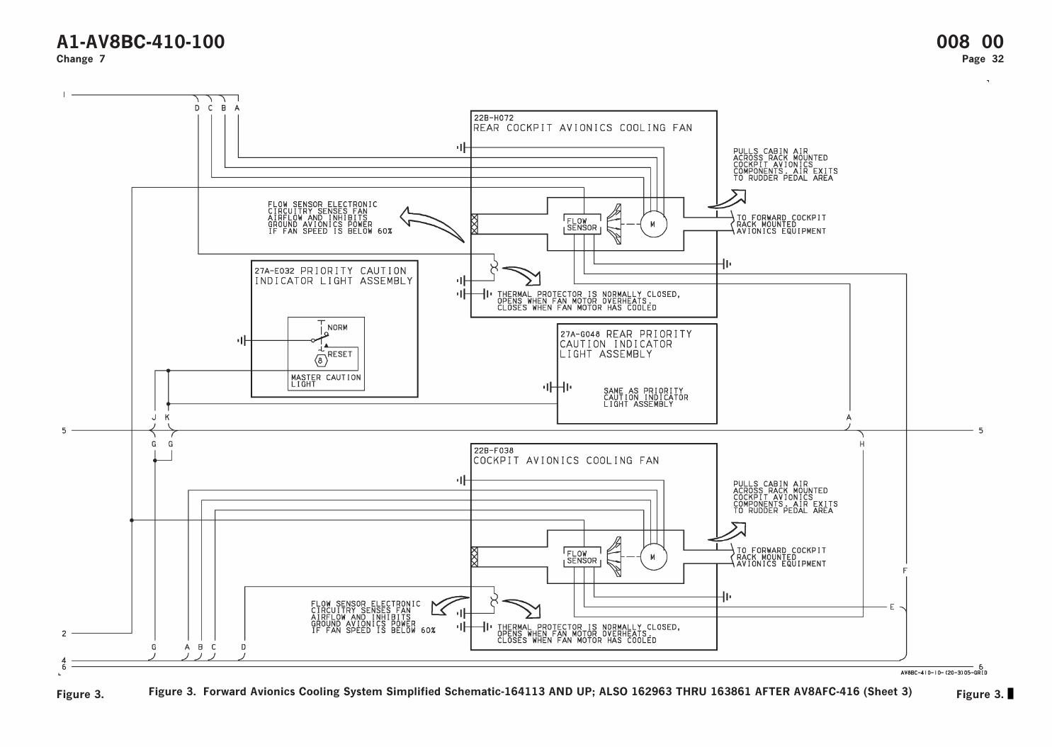
Figure 3. Forward Avionics Cooling System Simplified Schematic-164113 AND UP; ALSO 162963 THRU 163861 AFTER AV8AFC-416 (Sheet 3)
A1-AV8BC-410-100 008 00Change 7 Page 32
Figure 3. Figure 3.
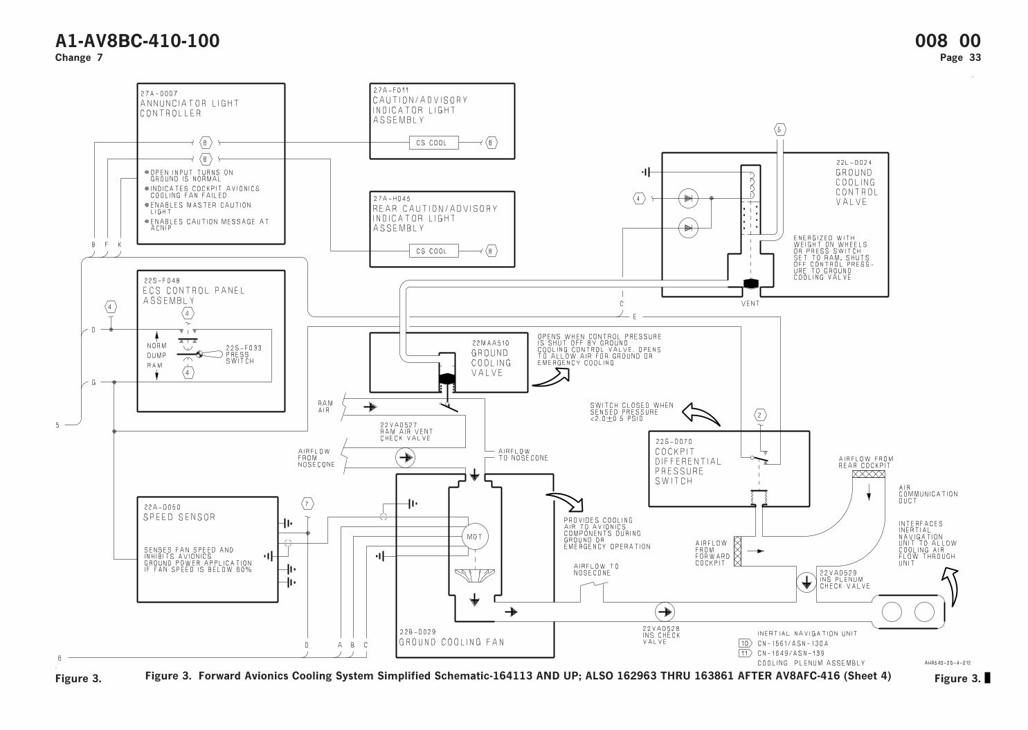
Figure 3. Forward Avionics Cooling System Simplified Schematic-164113 AND UP; ALSO 162963 THRU 163861 AFTER AV8AFC-416 (Sheet 4)
A1-AV8BC-410-100 008 00Change 7 Page 33
Figure 3. Figure 3.

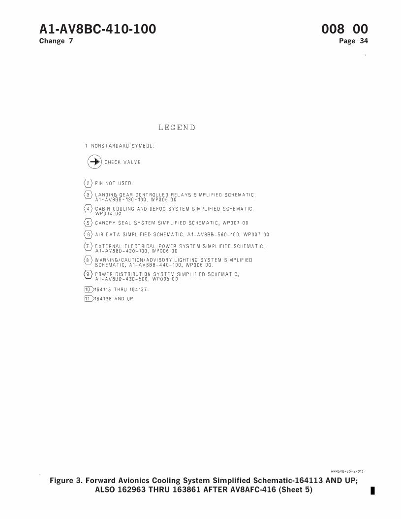
Figure 3. Forward Avionics Cooling System Simplified Schematic-164113 AND UP;ALSO 162963 THRU 163861 AFTER AV8AFC-416 (Sheet 5)
A1-AV8BC-410-100 008 00Change 7 Page 34

ORGANIZATIONAL MAINTENANCE
PRINCIPLES OF OPERATION
ANTI-G SYSTEM
Reference Material
Environmental Control System ...................................................................................... A1-AV8BC-410-100Description and Operation - Cabin Cooling And Defog System ....................... WP004 00
Alphabetical Index
Subject Page No.
Anti-G System Component Locator, Figure 1 ........................................................................................ 4Anti-G System Schematic, Figure 2 ......................................................................................................... 7Description ................................................................................................................................................... 2
Component Description...................................................................................................................... 2Anti-G/Canopy Seal Check Valve............................................................................................. 2Anti-G/Canopy Seal Test Port.................................................................................................. 2Anti-G Disconnect....................................................................................................................... 2Anti-G Valve ................................................................................................................................ 2Rear Anti-G Disconnect ............................................................................................................. 2Rear Anti-G Valve ...................................................................................................................... 2
Related Systems .................................................................................................................................. 2Cabin Cooling and Defog System ............................................................................................. 2
System Controls and Indicators........................................................................................................ 2Manual Inflation Buttons .......................................................................................................... 2
System Description ............................................................................................................................. 2Operation...................................................................................................................................................... 2
Component Operation ........................................................................................................................ 2Anti-G/Canopy Seal Check Valve............................................................................................. 3Anti-G/Canopy Seal Test Port.................................................................................................. 3Anti-G Disconnect....................................................................................................................... 3Anti-G Valve ................................................................................................................................ 2Rear Anti-G Disconnect ............................................................................................................. 3Rear Anti-G Valve ...................................................................................................................... 2
System Operation................................................................................................................................ 3Automatic Mode.......................................................................................................................... 3Ground Test................................................................................................................................. 3Manual Mode............................................................................................................................... 3
A1-AV8BC-410-100 009 001 February 1990 Page 1
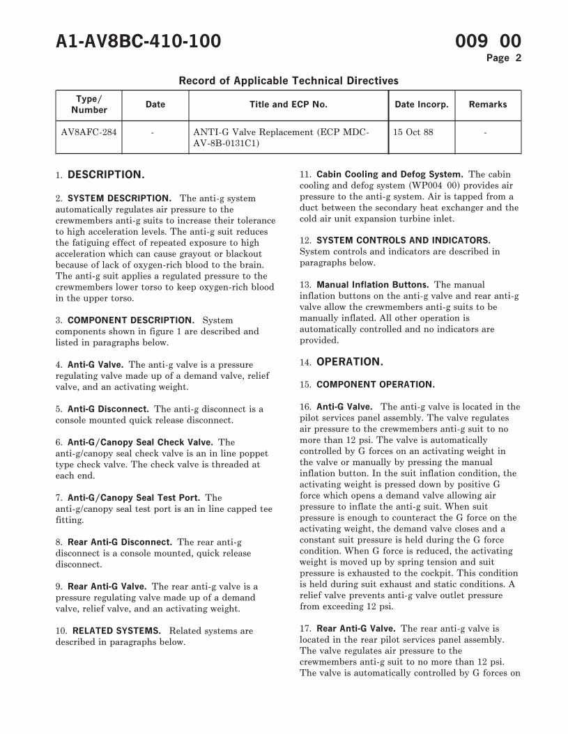
Record of Applicable Technical Directives
Type/
NumberDate Title and ECP No. Date Incorp. Remarks
AV8AFC-284 - ANTI-G Valve Replacement (ECP MDC-AV-8B-0131C1)
15 Oct 88 -
1. DESCRIPTION.
2. SYSTEM DESCRIPTION. The anti-g systemautomatically regulates air pressure to thecrewmembers anti-g suits to increase their toleranceto high acceleration levels. The anti-g suit reducesthe fatiguing effect of repeated exposure to highacceleration which can cause grayout or blackoutbecause of lack of oxygen-rich blood to the brain.The anti-g suit applies a regulated pressure to thecrewmembers lower torso to keep oxygen-rich bloodin the upper torso.
3. COMPONENT DESCRIPTION. Systemcomponents shown in figure 1 are described andlisted in paragraphs below.
4. Anti-G Valve. The anti-g valve is a pressureregulating valve made up of a demand valve, reliefvalve, and an activating weight.
5. Anti-G Disconnect. The anti-g disconnect is aconsole mounted quick release disconnect.
6. Anti-G/Canopy Seal Check Valve. Theanti-g/canopy seal check valve is an in line poppettype check valve. The check valve is threaded ateach end.
7. Anti-G/Canopy Seal Test Port. Theanti-g/canopy seal test port is an in line capped teefitting.
8. Rear Anti-G Disconnect. The rear anti-gdisconnect is a console mounted, quick releasedisconnect.
9. Rear Anti-G Valve. The rear anti-g valve is apressure regulating valve made up of a demandvalve, relief valve, and an activating weight.
10. RELATED SYSTEMS. Related systems aredescribed in paragraphs below.
11. Cabin Cooling and Defog System. The cabincooling and defog system (WP004 00) provides airpressure to the anti-g system. Air is tapped from aduct between the secondary heat exchanger and thecold air unit expansion turbine inlet.
12. SYSTEM CONTROLS AND INDICATORS.
System controls and indicators are described inparagraphs below.
13. Manual Inflation Buttons. The manualinflation buttons on the anti-g valve and rear anti-gvalve allow the crewmembers anti-g suits to bemanually inflated. All other operation isautomatically controlled and no indicators areprovided.
14. OPERATION.
15. COMPONENT OPERATION.
16. Anti-G Valve. The anti-g valve is located in thepilot services panel assembly. The valve regulatesair pressure to the crewmembers anti-g suit to nomore than 12 psi. The valve is automaticallycontrolled by G forces on an activating weight inthe valve or manually by pressing the manualinflation button. In the suit inflation condition, theactivating weight is pressed down by positive Gforce which opens a demand valve allowing airpressure to inflate the anti-g suit. When suitpressure is enough to counteract the G force on theactivating weight, the demand valve closes and aconstant suit pressure is held during the G forcecondition. When G force is reduced, the activatingweight is moved up by spring tension and suitpressure is exhausted to the cockpit. This conditionis held during suit exhaust and static conditions. Arelief valve prevents anti-g valve outlet pressurefrom exceeding 12 psi.
17. Rear Anti-G Valve. The rear anti-g valve islocated in the rear pilot services panel assembly.The valve regulates air pressure to thecrewmembers anti-g suit to no more than 12 psi.The valve is automatically controlled by G forces on
A1-AV8BC-410-100 009 00Page 2
an activating weight in the valve or manually bypressing the manual inflation button. In the suitinflation condition, the activating weight is presseddown by positive G force which opens a demandvalve allowing air pressure to inflate the anti-g suit.When suit pressure is enough to counteract the Gforce on the activating weight, the demand valvecloses and constant suit pressure is held during theG force condition. When G force is reduced, theactivating weight is moved up by spring tension andsuit pressure is exhausted to the rear cockpit. Thiscondition is held during suit exhaust and staticconditions. A relief valve prevents anti-g valveoutlet pressure from exceeding 12 psi.
18. Anti-G Disconnect. The anti-g disconnect,located inboard of the pilot services panel assembly,provides the quick disconnect interface between theanti-g system and the crewmembers anti-g suit.
19. Rear Anti-G Disconnect. The rear anti-gdisconnect, located inboard of the rear pilot servicespanel assembly, provides the quick disconnectinterface between the anti-g system and thecrewmembers anti-g suit.
20. Anti-G/Canopy Seal Check Valve. Theanti-g/canopy seal check valve is a one way checkvalve. The valve is located in the air duct betweenthe secondary heat exchanger and the cold air unitexpansion turbine inlet. The check valve willprevent loss of anti-g system pressure if loss ofcabin cooling and defog system (WP004 00)pressure occurs. The check valve also isolates theanti-g system so a ground air source can be used.
21. Anti-G/Canopy Seal Test Port. Theanti-g/canopy seal test port is located in theforward end of the nose wheelwell. The test portallows a ground air source to be used for groundtesting of the anti-g system.
22. SYSTEM OPERATION.
23. Automatic Mode. Air pressure, tapped fromthe cabin cooling and defog system (WP004 00),passes through the anti-g/canopy seal check valve(figure 2) to the anti-g valves. Positive G forcesmove an activating weight down opening a demandvalve allowing air pressure to inflate the anti-g suit.When G forces decrease the activating weight ismoved up by spring tension closing the demandvalve and opening an exhaust valve, allowing theanti-g suit to deflate.
24. Manual Mode. Air pressure, tapped from thecabin cooling and defog system (WP004 00), passesthrough the anti-g/canopy seal check valve (figure2) to the anti-g valves. Pressing the manualinflation button moves an activating weight downopening a demand valve allowing air pressure toinflate the anti-g suit. When the manual inflationbutton is released, the activating weight is movedup by spring tension, closing the demand valve andopening an exhaust valve, allowing the anti-g suit todeflate.
25. Ground Test. With a ground air source applied,the anti-g system can be operated manually. Thesystem operation is the same for ground test orin-flight manual operation.
A1-AV8BC-410-100 009 00Page 3
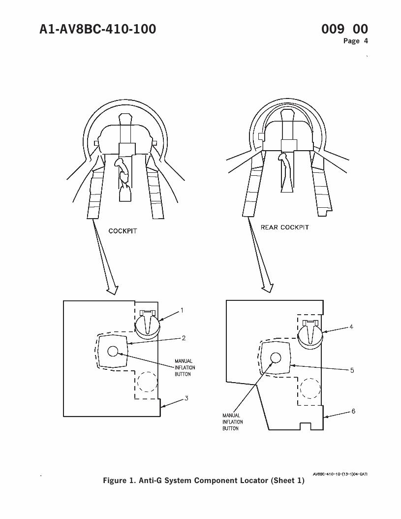
Figure 1. Anti-G System Component Locator (Sheet 1)
A1-AV8BC-410-100 009 00Page 4
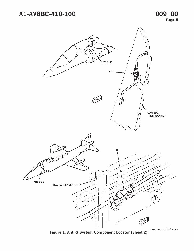
Figure 1. Anti-G System Component Locator (Sheet 2)
A1-AV8BC-410-100 009 00Page 5

Nomenclature Index No. Ref Des
ANTI-G/CANOPY SEAL CHECK VALVE 7 22VAK516
ANTI-G/CANOPY SEAL TEST PORT 8 —
ANTI-G DISCONNECT 1 —
ANTI-G VALVE 2 22VAE515
PILOT SERVICES PANEL ASSEMBLY 3 52A-E060
REAR ANTI-G DISCONNECT 4 —
REAR ANTI-G VALVE 5 22VAG530
REAR PILOT SERVICES PANEL ASSEMBLY 6 8A-G195
A1-AV8BC-410-100 009 00Page 6
Figure 1. Anti-G System Component Locator (Sheet 3)
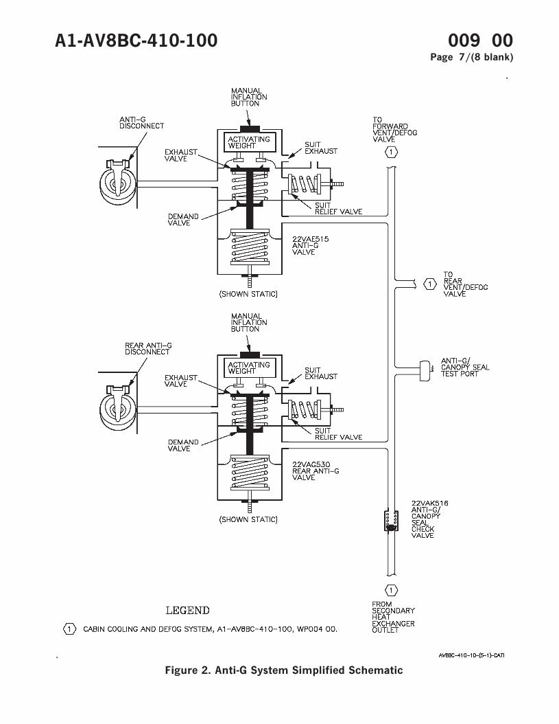
Figure 2. Anti-G System Simplified Schematic
A1-AV8BC-410-100 009 00Page 7/(8 blank)


ORGANIZATIONAL MAINTENANCE
PRINCIPLES OF OPERATION
REAR EQUIPMENT COOLING SYSTEM
Reference Material
Electrical Systems............................................................................................................. A1-AV8BB-420-100AC Power System ..................................................................................................... WP003 00DC Power System ..................................................................................................... WP004 00
Electrical Systems............................................................................................................. A1-AV8BD-420-100AC Power System ..................................................................................................... WP003 00DC Power System ..................................................................................................... WP004 00
Lighting Systems............................................................................................................... A1-AV8BB-440-100Warning/Caution/Advisory Lighting System........................................................ WP007 00
Power Plant and Related Systems ................................................................................. A1-AV8BD-290-100Basic Engine .............................................................................................................. WP003 00
Alphabetical Index
Subject Page No.
Description ................................................................................................................................................... 2AComponent Description...................................................................................................................... 2A
Avionics Cooling Air Fittings .................................................................................................... 2ARear ECS Air Filter Assembly .................................................................................................. 2ARear ECS Air Inlet Temperature Switch ................................................................................ 3Rear ECS Check Valve............................................................................................................... 3Rear ECS Cold Air Unit ............................................................................................................ 3Rear ECS Cold Air Unit Pressure Switch............................................................................... 3Rear ECS Ground Cooling Fan................................................................................................. 3Rear ECS Ground Cooling Fan Pressure Switch ................................................................... 3Rear ECS Ground Cooling Fan Speed Sensor........................................................................ 3Rear ECS Ground Cooling Valve.............................................................................................. 3Rear ECS Heat Exchanger ........................................................................................................ 3Rear ECS Pressure Reducing and Shutoff Valve................................................................... 3Rear ECS Temperature Control Valve .................................................................................... 3Rear ECS Temperature Sensor................................................................................................. 3
Related Systems .................................................................................................................................. 3AC Power System........................................................................................................................ 3DC Power System ....................................................................................................................... 3Power Plant and Related Systems ........................................................................................... 3Warning/Caution/Advisory Lighting System.......................................................................... 3
System Controls and Indicators........................................................................................................ 4AFT BAY Caution Light ........................................................................................................... 4EQUIP Switch ............................................................................................................................. 4
A1-AV8BC-410-100 010 00Change 7 - 15 May 2004 Page 1
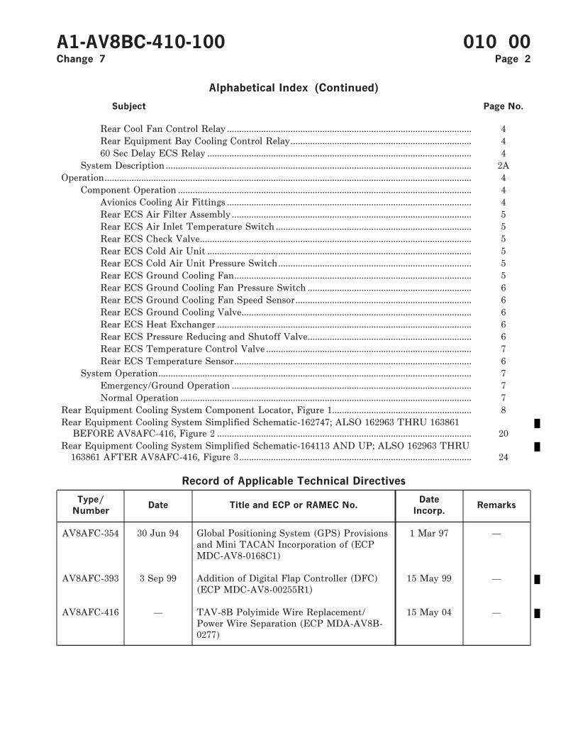
Alphabetical Index (Continued)
Subject Page No.
Rear Cool Fan Control Relay .................................................................................................... 4Rear Equipment Bay Cooling Control Relay.......................................................................... 460 Sec Delay ECS Relay ............................................................................................................ 4
System Description ............................................................................................................................. 2AOperation...................................................................................................................................................... 4
Component Operation ........................................................................................................................ 4Avionics Cooling Air Fittings .................................................................................................... 4Rear ECS Air Filter Assembly .................................................................................................. 5Rear ECS Air Inlet Temperature Switch ................................................................................ 5Rear ECS Check Valve............................................................................................................... 5Rear ECS Cold Air Unit ............................................................................................................ 5Rear ECS Cold Air Unit Pressure Switch............................................................................... 5Rear ECS Ground Cooling Fan................................................................................................. 5Rear ECS Ground Cooling Fan Pressure Switch ................................................................... 6Rear ECS Ground Cooling Fan Speed Sensor........................................................................ 6Rear ECS Ground Cooling Valve.............................................................................................. 6Rear ECS Heat Exchanger ........................................................................................................ 6Rear ECS Pressure Reducing and Shutoff Valve................................................................... 6Rear ECS Temperature Control Valve .................................................................................... 7Rear ECS Temperature Sensor................................................................................................. 6
System Operation................................................................................................................................ 7Emergency/Ground Operation .................................................................................................. 7Normal Operation ....................................................................................................................... 7
Rear Equipment Cooling System Component Locator, Figure 1......................................................... 8Rear Equipment Cooling System Simplified Schematic-162747; ALSO 162963 THRU 163861
BEFORE AV8AFC-416, Figure 2 ........................................................................................................ 20Rear Equipment Cooling System Simplified Schematic-164113 AND UP; ALSO 162963 THRU
163861 AFTER AV8AFC-416, Figure 3............................................................................................... 24
Record of Applicable Technical Directives
Type/
NumberDate Title and ECP or RAMEC No.
Date
Incorp.Remarks
AV8AFC-354 30 Jun 94 Global Positioning System (GPS) Provisionsand Mini TACAN Incorporation of (ECPMDC-AV8-0168C1)
1 Mar 97 —
AV8AFC-393 3 Sep 99 Addition of Digital Flap Controller (DFC)(ECP MDC-AV8-00255R1)
15 May 99 —
AV8AFC-416 — TAV-8B Polyimide Wire Replacement/Power Wire Separation (ECP MDA-AV8B-0277)
15 May 04 —
A1-AV8BC-410-100 010 00Change 7 Page 2

1. DESCRIPTION.
2. SYSTEM DESCRIPTION. Aft fuselage mountedavionics equipment is cooled by the rear equipmentcooling system. Engine bleed air, extracted from thesixth stage of compression, is conditioned anddistributed to the rack mounted avionics equipmentto provide required cooling.
3. COMPONENT DESCRIPTION. Systemcomponents shown in figure 1 are described andlisted in paragraphs below.
4. Avionics Cooling Air Fittings. Several differenttypes of fittings are used. Cooling requirements andmounting provisions vary for different avionicsunits. Some fittings are collapsible, self sealingassemblies. Others are duct flanges. Fittings may ormay not include filters and/or orifices.
5. Rear ECS Air Filter Assembly. The rear ECS airfilter assembly is a reusable, steel mesh filterelement encased in a housing with a spring loadedbypass valve.
A1-AV8BC-410-100 010 00Change 6 Page 2A/(2B blank)

6. Rear ECS Air Inlet Temperature Switch. Therear ECS air inlet temperature switch is atemperature sensitive switch encased in a threadedhousing.
7. Rear ECS Check Valve. The rear ECS checkvalve is a flapper type, in line, spring loaded closed,check valve.
8. Rear ECS Cold Air Unit. The rear ECS cold airunit is an expansion turbine and axial flow fan,mounted at opposite ends of a common shaft, in acommon housing. The unit has a serviceable bearinglubrication system and a bearing cooling system.
9. Rear ECS Cold Air Unit Pressure Switch. Therear ECS cold air unit pressure switch is a pressuresensitive electrical switch encased in a threadedhousing.
10. Rear ECS Ground Cooling Fan. The rear ECSground cooling fan is an electrically driven axialflow fan. The fan is made up of a flow impellermounted directly to the shaft of a 3 phase, 400 Hzelectrical motor. The motor and impeller areenclosed in a housing with guide vanes built in onthe outlet end of the impeller. The motor has anelectrical sensing unit and overheat protectiondevices.
11. Rear ECS Ground Cooling Fan Pressure
Switch. The rear ECS ground cooling fan pressureswitch is a pressure sensitive electrical switchencased in a threaded housing.
12. Rear ECS Ground Cooling Fan Speed Sensor.
The rear ECS ground cooling fan speed sensor is anelectronic processing unit in a sealed case.
13. Rear ECS Ground Cooling Valve. The rearECS ground cooling valve is a two positionpneumatically actuated and controlled valve. Thevalve is made up of a housing which contains apiston attached to a spring loaded diaphragm thatcontrols a hinged valve.
14. Rear ECS Heat Exchanger. The rear ECS heatexchanger is a single pass, cross flow, air to air heatexchanger. The heat exchanger is made up of afinned core inside a welded housing.
15. Rear ECS Pressure Reducing and Shutoff
Valve. The rear ECS pressure reducing and shutoffvalve is a solenoid controlled pressure regulatingand shutoff valve in a single unit. Both the pressure
regulating section and shutoff valve section aremade up of a piston sliding within a cylinder on ahollow shaft. The shutoff valve section piston isspring loaded closed and the pressure regulatingsection piston is spring loaded open. The pressureregulating section also has a blowoff valve.
16. Rear ECS Temperature Sensor. The rear ECStemperature sensor is a temperature sensitivecontrol device made up of a body, a bimetallictemperature sensitive strip with a valve seatconnected to one end, and an orifice adapter.
17. Rear ECS Temperature Control Valve. Therear ECS temperature control valve is apneumatically controlled and actuated flow controlvalve. The valve is made up of a body enclosing aspring-loaded double-action piston and hollow shaftattached to a poppet valve and an orifice filter. Thevalve is spring loaded closed.
18. RELATED SYSTEMS. Related systems aredescribed in paragraphs below.
19. Power Plant and Related Systems. Hot, highpressure bleed air is provided by the engine sixthstage compressor (A1-AV8BD-290-100, WP003 00).
20. DC Power System. The DC power system on162747; ALSO 162963 THRU 163861 BEFOREAV8AFC-416 (A1-AV8BB-420-100, WP004 00) or164113 AND UP; ALSO 162963 THRU 163861AFTER AV8AFC-416 (A1-AV8BD-420-100, WP00400) provides 28vdc essential power for the rearequipment cooling system.
21. AC Power System. The AC power system on162747; ALSO 162963 THRU 163861 BEFOREAV8AFC-416 (A1-AV8BB-420-100, WP003 00) or164113 AND UP; ALSO 162963 THRU 163861AFTER AV8AFC-416 (A1-AV8BD-420-100, WP00300) provides essential 115vac for the rear equipmentcooling system.
22. Warning/Caution/Advisory Lighting System.
The warning/caution/advisory lighting system(A1-AV8BB-440-100, WP007 00) provides visualindication of normal aircraft functions and systemmalfunctions affecting safety of flight operations.The warning/caution/advisory lighting systemincludes the annunciator light controller and thecaution/advisory indicator light assembly. Theannunciator light controller receives data fromvarious aircraft systems and provides logic to turnon and off warning/caution/advisory lights.
A1-AV8BC-410-100 010 00Change 7 Page 3
23. The annunciator light controller will turn onthe AFT BAY caution lights and the MASTERCAUTION lights when the rear equipment coolingsystem is off.
24. SYSTEM CONTROLS AND INDICATORS.
System controls and indicators are described inparagraphs below.
25. EQUIP Switch. The EQUIP switch, located onthe ECS control panel assembly, is a dual poletoggle switch. The switch provides electrical controlfor the rear ECS pressure reducing and shutoffvalve. The switch has three positions: RESET, ON,and OFF. The switch must be held in RESET.
26. Setting the EQUIP switch to ON appliesessential 28vdc power to contacts of the rearequipment bay cooling control relay.
27. Setting the EQUIP switch to OFF appliesessential 28vdc power to a contact of the rearequipment bay cooling control relay and energizesthe rear ECS pressure reducing and shutoff valvesolenoid. Energizing the solenoid closes the valve.Power applied to rear equipment bay coolingcontrol relay contacts with the EQUIP switch ON isremoved with the EQUIP switch OFF.
28. Setting and holding the EQUIP switch toRESET removes essential 28vdc power from therear equipment bay cooling control relay contactand from the rear ECS pressure reducing andshutoff valve solenoid, opening the valve.
29. AFT BAY Caution Lights. The AFT BAYcaution lights, located on the caution/advisoryindicator light assembly and the rearcaution/advisory indicator light assembly are yellowlens, dual lamp, indicator lights.
30. The AFT BAY caution lights are controlled bythe rear ECS air inlet temperature switch, or therear ECS cold air unit pressure switch, through thewarning/caution/ advisory lighting system.
31. Rear Cool Fan Control Relay. The rear cool fancontrol relay, located on the distribution panelassembly, is a four pole, double throw, 5 amperes,permanent magnet drive, armature relay.
32. The relay is controlled by the rear ECS groundcooling fan pressure switch. With the relayenergized, essential 115vac is removed from the rearECS ground cooling fan. With the relay
deenergized, essential 115vac is applied to the rearECS ground cooling fan.
33. Rear Equipment Bay Cooling Control Relay.
The rear equipment bay cooling control relay,located on the distribution panel assembly, is a dualpole, double throw, 5 amperes, permanent magnetdrive, armature relay.
34. The relay is controlled by the rear ECS air inlettemperature switch or the rear ECS cold air unitpressure unit switch. With the relay energized, thefollowing occurs:
a. Essential 28vdc power is applied to energizethe rear ECS pressure reducing and shutoff valvesolenoid.
b. Essential 28vdc power is removed from theannunciator light controller to enable the AFT BAYcaution lights.
35. With the relay deenergized, the followingoccurs:
a. Essential 28vdc power is removed todeenergize the rear ECS pressure reducing andshutoff valve solenoid.
b. Essential 28vdc power is applied to theannunciator light controller to disable the AFTBAY caution lights.
36. 60 Sec Delay ECS Relay. The 60 sec delay ECSrelay, located on the aft relay panel assembly is atime delay, 10 amperes, dual pole, double throw,armature. The relay contacts move 60 seconds afterthe relay is energized. When deenergized, thecontacts move immediately.
37. The relay is controlled by the rear ECS cold airunit pressure switch. With the relay energized,essential 28vdc power is applied to the input of therear ECS air inlet temperature switch. With therelay deenergized, essential 28vdc power is removedfrom the input of the rear ECS air inlettemperature switch.
38. OPERATION.
39. COMPONENT OPERATION.
40. Avionics Cooling Air Fittings. Avionics coolingair fittings, located on the equipment cooling rack,provide the cooling system interface between rack
A1-AV8BC-410-100 010 00Page 4
mounted equipment and the equipment rack. Whena unit is installed on the equipment rack, it makescontact with a cooling air fitting. The fitting makesa seal between the unit and the rack, allowingcooling air to flow through the unit. Some fittingscontact the unit on the back and some contact thebottom, depending on unit mounting. The differenttypes of fittings used are required for the differentcooling requirements of each unit.
41. Rear ECS Air Filter Assembly. The rear ECSair filter element assembly is located in the MLGwheelwell. Sixth stage engine bleed air is sent byway of ducting to the filter assembly. The filterremoves particulate contamination before it cancause damage further downstream in the rearequipment cooling system. If the filter elementbecomes blocked, pressure build up opens a bypassvalve allowing air to bypass the filter element. Thebypass valve opens at 4 psid. The filter element isreplaceable independent of the housing or may becleaned and reused. With the element removed, thehousing allows a ground air source to be adaptedand used for ground operational checkout.
42. Rear ECS Air Inlet Temperature Switch. Therear ECS air inlet temperature switch is located inthe equipment cooling shelf supply duct. Ifequipment cooling air exceeds 131°F, thetemperature switch closes and applies essential28vdc to energize the rear equipment bay coolingcontrol relay. When equipment cooling air decreasesto less than 130°F, the temperature switch opens toenable the rear equipment bay cooling control relayto be manually reset. After an overheat occurs, thesystem must be manually reset, using the EQUIPswitch located on the ECS control panel assembly.
43. Rear ECS Check Valve. The rear ECS checkvalve is located in the left hand rear equipmentcooling system exhaust duct. The check valveprevents reverse airflow from being induced into thesystem during ground operation. The check valvealso prevents the ingestion of foreign objects intothe system.
44. Rear ECS Cold Air Unit. The rear ECS cold airunit is located at the base of the rear ECS heatexchanger in door 61. The expansion turbinereceives pre-cooled air from the rear ECS heatexchanger. Heat energy is converted to mechanicalenergy by spinning the expansion turbine. Theturbine drives the axial flow fan through thecommon shaft. With the heat lost, cold air is left
and sent by way of ducting to mix with hot air fromthe rear ECS temperature control valve.
45. During ground operation, the driven axial flowfan draws ram air across the rear ECS heatexchanger. The ram air then exits through the ramair exhaust.
46. Lubrication for the common shaft is providedby oil stored in a cotton wool pack sump andtransported to the shaft by a system of oil wicks.The sump has fill and drain plugs located to allowperiodic servicing of oil while the unit is still in theaircraft.
47. Shaft bearing cooling is provided by a tube,tapped into the ram air inlet, which transportscooling air to the shaft bearings.
48. Rear ECS Cold Air Unit Pressure Switch. Therear ECS cold air unit pressure switch is located inthe rear ECS cold air unit expansion turbine inletduct. When turbine inlet pressure exceeds 72 psi,the pressure switch closes and applies essential28vdc to energize the rear equipment bay coolingcontrol relay. When turbine inlet pressure decreasesto below 72 psi, the switch opens to enable the rearequipment bay cooling control relay to be manuallyreset. After an overpressure occurs, the system mustbe manually reset, using the EQUIP switch locatedon the ECS control panel assembly.
49. Rear ECS Ground Cooling Fan. The rear ECSground cooling fan is located in a duct tapped fromthe rear ECS ram air inlet in door 61. With the fanoperating, air is pulled in through the rear ECS ramair inlet. The cooling air is given a high velocity bythe fan impeller and is transported by way ofducting to the equipment cooling rack. The fan willoperate when electrical power is applied and rearequipment cooling system pressure is less than 5.0psi.
50. The guide vanes straighten the airflow beforedischarge from the fan. The electrical sensing unitprovides an electrical signal to the rear ECS groundcooling fan speed sensor based on fan speed. Theoverheat protection devices will automatically stopthe fan, if an overheat condition occurs. When theoverheat condition no longer exists, the fan willresume normal operation. The fan motor is cooledby its own airflow.
A1-AV8BC-410-100 010 00Page 5
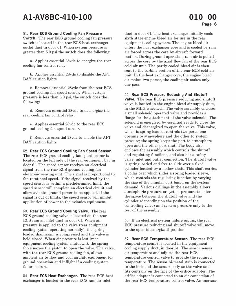
51. Rear ECS Ground Cooling Fan Pressure
Switch. The rear ECS ground cooling fan pressureswitch is located in the rear ECS heat exchangeroutlet duct in door 61. When system pressure isgreater than 5.0 psi the switch does the following:
a. Applies essential 28vdc to energize the rearcooling fan control relay.
b. Applies essential 28vdc to disable the AFTBAY caution lights.
c. Removes essential 28vdc from the rear ECSground cooling fan speed sensor. When systempressure is less than 5.0 psi, the switch does thefollowing:
d. Removes essential 28vdc to deenergize therear cooling fan control relay.
e. Applies essential 28vdc to the rear ECSground cooling fan speed sensor.
f. Removes essential 28vdc to enable the AFTBAY caution lights.
52. Rear ECS Ground Cooling Fan Speed Sensor.
The rear ECS ground cooling fan speed sensor islocated on the left side of the rear equipment bay indoor 61. The speed sensor receives an electricalsignal from the rear ECS ground cooling fanelectronic sensing unit. The signal is proportional tofan rotational speed. If the signal received by thespeed sensor is within a predetermined limit, thespeed sensor will complete an electrical circuit andallow avionics ground power to be applied. If thesignal is out of limits, the speed sensor will inhibitapplication of power to the avionics equipment.
53. Rear ECS Ground Cooling Valve. The rearECS ground cooling valve is located on the rearECS ram air inlet duct in door 61. When airpressure is applied to the valve (rear equipmentcooling system operating normally), the springloaded diaphragm is compressed and the valve isheld closed. When air pressure is lost (rearequipment cooling system shutdown), the springforce moves the piston to open the valve. The valve,with the rear ECS ground cooling fan, allowsambient air to flow and cool aircraft equipment forground operation and inflight if a cooling systemfailure occurs.
54. Rear ECS Heat Exchanger. The rear ECS heatexchanger is located in the rear ECS ram air inlet
duct in door 61. The heat exchanger initially coolssixth stage engine bleed air for use in the rearequipment cooling system. The engine bleed airenters the heat exchanger core and is cooled by ramair forced across the core by aircraft forwardmotion. During ground operation, ram air is pulledacross the core by the axial flow fan of the rear ECScold air unit. The partly cooled bleed air is thensent to the turbine section of the rear ECS cold airunit. In the heat exchanger core, the engine bleedair makes two passes, the cooling air makes onlyone pass.
55. Rear ECS Pressure Reducing And Shutoff
Valve. The rear ECS pressure reducing and shutoffvalve is located in the engine bleed air supply duct,in the MLG wheelwell. The valve assembly enclosesa small solenoid operated valve and provides aflange for the attachment of the valve solenoid. Thesolenoid is energized by essential 28vdc to close thevalve and deenergized to open the valve. This valve,which is spring loaded, controls two ports, oneopening to atmosphere and the other to systempressure; the spring keeps the port to atmosphereopen and the other port shut. The body alsoencloses the assembly which controls the shutoffand regulating functions, and also has a safetyvalve, inlet and outlet connection. The shutoff valveis spring loaded and free to slide over a fixedcylinder located by a hollow shaft. This shaft carriesa collar over which slides a spring loaded sleeve,which controls the regulating function by varyingthe size of the annular port based on the systemdemand. Various drillings in the assembly allowsatmospheric pressure or system pressure to enterthe space between the shutoff valve and thecylinder (depending on the position of thecontrolling valve) and system pressure only to therest of the assembly.
56. If an electrical system failure occurs, the rearECS pressure reducing and shutoff valve will moveto the open (deenergized) position.
57. Rear ECS Temperature Sensor. The rear ECStemperature sensor is located in the equipmentcooling supply duct, in door 61. The sensor sensesair temperature and adjusts the rear ECStemperature control valve to provide the requiredtemperature. The sensor bi-metal strip is connectedto the inside of the sensor body so the valve seatfits centrally on the face of the orifice adapter. Theorifice adapter is connected to an air connection ofthe rear ECS temperature control valve. An increase
A1-AV8BC-410-100 010 00Page 6
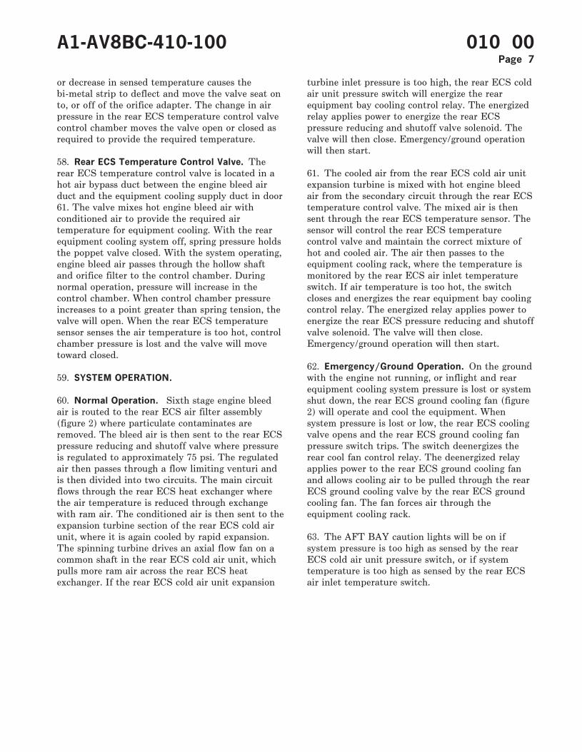
or decrease in sensed temperature causes thebi-metal strip to deflect and move the valve seat onto, or off of the orifice adapter. The change in airpressure in the rear ECS temperature control valvecontrol chamber moves the valve open or closed asrequired to provide the required temperature.
58. Rear ECS Temperature Control Valve. Therear ECS temperature control valve is located in ahot air bypass duct between the engine bleed airduct and the equipment cooling supply duct in door61. The valve mixes hot engine bleed air withconditioned air to provide the required airtemperature for equipment cooling. With the rearequipment cooling system off, spring pressure holdsthe poppet valve closed. With the system operating,engine bleed air passes through the hollow shaftand orifice filter to the control chamber. Duringnormal operation, pressure will increase in thecontrol chamber. When control chamber pressureincreases to a point greater than spring tension, thevalve will open. When the rear ECS temperaturesensor senses the air temperature is too hot, controlchamber pressure is lost and the valve will movetoward closed.
59. SYSTEM OPERATION.
60. Normal Operation. Sixth stage engine bleedair is routed to the rear ECS air filter assembly(figure 2) where particulate contaminates areremoved. The bleed air is then sent to the rear ECSpressure reducing and shutoff valve where pressureis regulated to approximately 75 psi. The regulatedair then passes through a flow limiting venturi andis then divided into two circuits. The main circuitflows through the rear ECS heat exchanger wherethe air temperature is reduced through exchangewith ram air. The conditioned air is then sent to theexpansion turbine section of the rear ECS cold airunit, where it is again cooled by rapid expansion.The spinning turbine drives an axial flow fan on acommon shaft in the rear ECS cold air unit, whichpulls more ram air across the rear ECS heatexchanger. If the rear ECS cold air unit expansion
turbine inlet pressure is too high, the rear ECS coldair unit pressure switch will energize the rearequipment bay cooling control relay. The energizedrelay applies power to energize the rear ECSpressure reducing and shutoff valve solenoid. Thevalve will then close. Emergency/ground operationwill then start.
61. The cooled air from the rear ECS cold air unitexpansion turbine is mixed with hot engine bleedair from the secondary circuit through the rear ECStemperature control valve. The mixed air is thensent through the rear ECS temperature sensor. Thesensor will control the rear ECS temperaturecontrol valve and maintain the correct mixture ofhot and cooled air. The air then passes to theequipment cooling rack, where the temperature ismonitored by the rear ECS air inlet temperatureswitch. If air temperature is too hot, the switchcloses and energizes the rear equipment bay coolingcontrol relay. The energized relay applies power toenergize the rear ECS pressure reducing and shutoffvalve solenoid. The valve will then close.Emergency/ground operation will then start.
62. Emergency/Ground Operation. On the groundwith the engine not running, or inflight and rearequipment cooling system pressure is lost or systemshut down, the rear ECS ground cooling fan (figure2) will operate and cool the equipment. Whensystem pressure is lost or low, the rear ECS coolingvalve opens and the rear ECS ground cooling fanpressure switch trips. The switch deenergizes therear cool fan control relay. The deenergized relayapplies power to the rear ECS ground cooling fanand allows cooling air to be pulled through the rearECS ground cooling valve by the rear ECS groundcooling fan. The fan forces air through theequipment cooling rack.
63. The AFT BAY caution lights will be on ifsystem pressure is too high as sensed by the rearECS cold air unit pressure switch, or if systemtemperature is too high as sensed by the rear ECSair inlet temperature switch.
A1-AV8BC-410-100 010 00Page 7
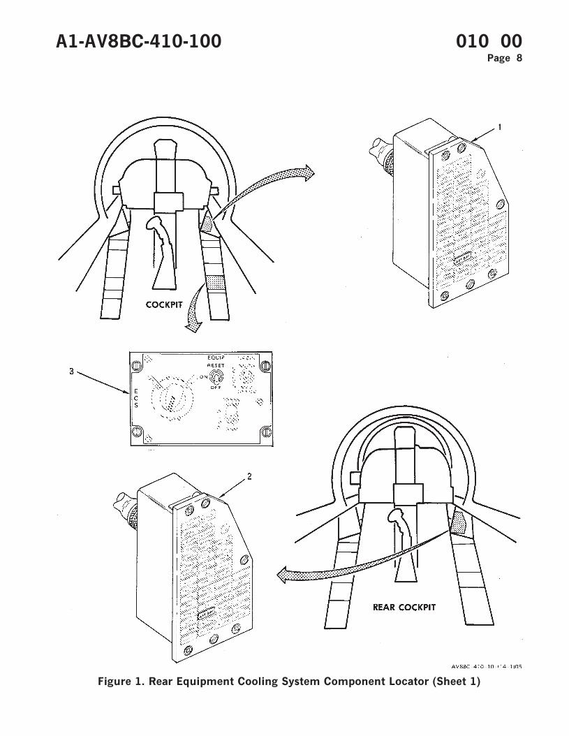
Figure 1. Rear Equipment Cooling System Component Locator (Sheet 1)
A1-AV8BC-410-100 010 00Page 8
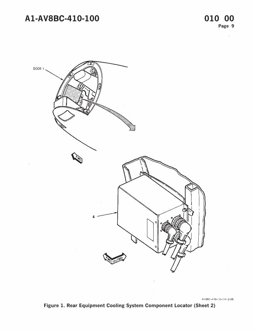
Figure 1. Rear Equipment Cooling System Component Locator (Sheet 2)
A1-AV8BC-410-100 010 00Page 9
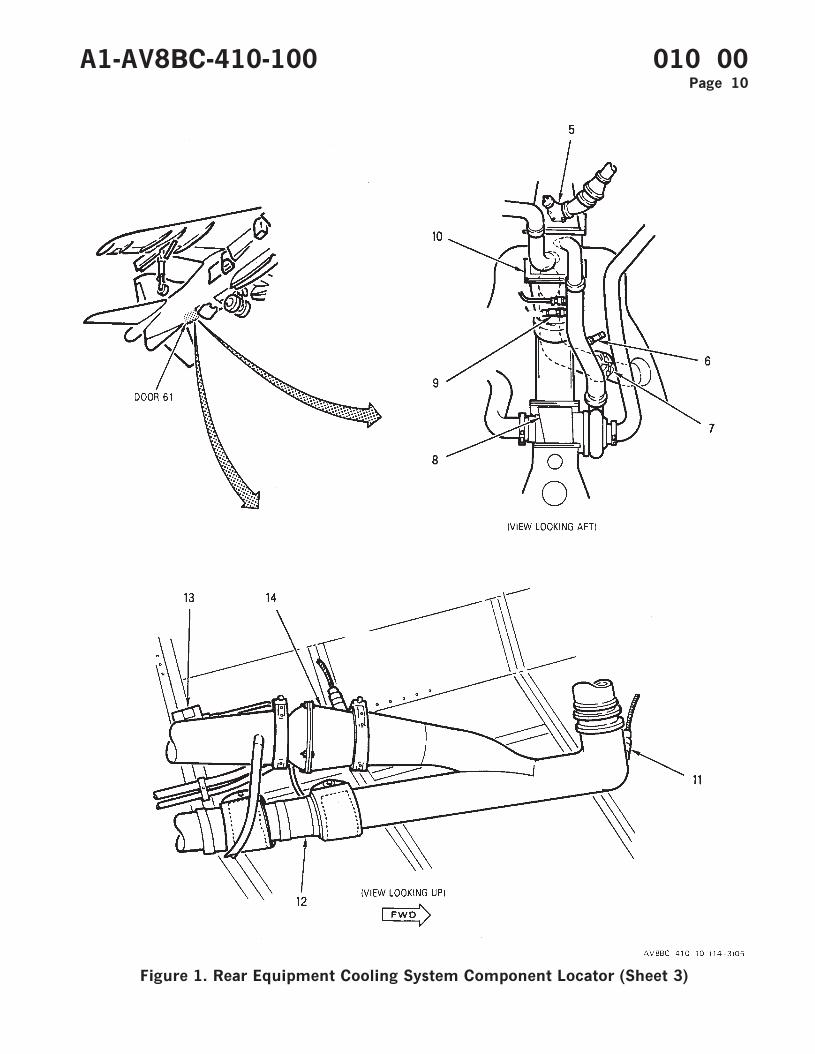
Figure 1. Rear Equipment Cooling System Component Locator (Sheet 3)
A1-AV8BC-410-100 010 00Page 10
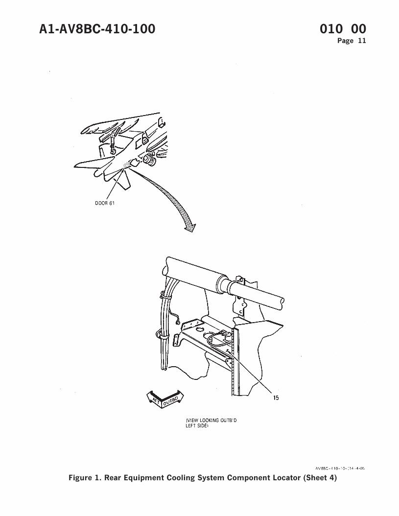
Figure 1. Rear Equipment Cooling System Component Locator (Sheet 4)
A1-AV8BC-410-100 010 00Page 11
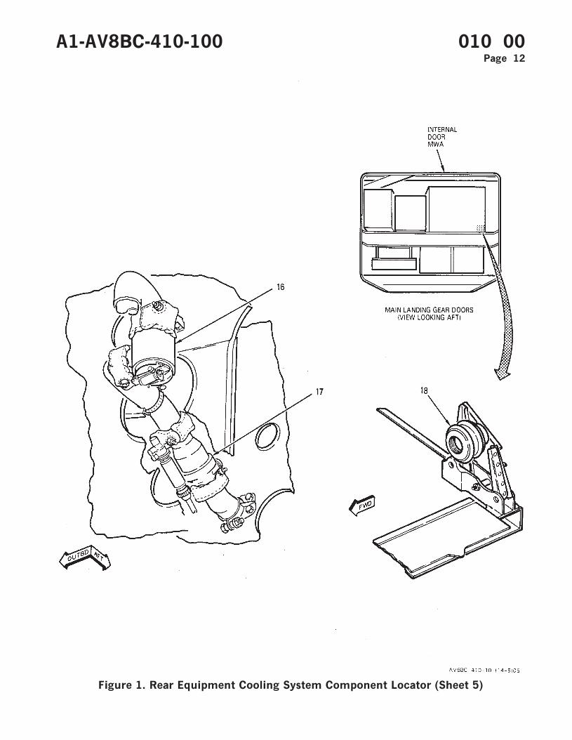
Figure 1. Rear Equipment Cooling System Component Locator (Sheet 5)
A1-AV8BC-410-100 010 00Page 12

Figure 1. Rear Equipment Cooling System Component Locator (Sheet 6)
A1-AV8BC-410-100 010 00Page 13
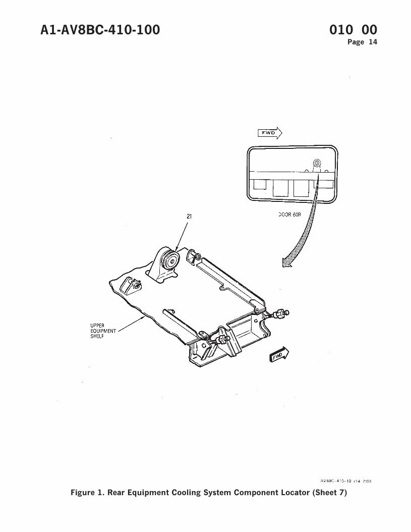
Figure 1. Rear Equipment Cooling System Component Locator (Sheet 7)
A1-AV8BC-410-100 010 00Page 14
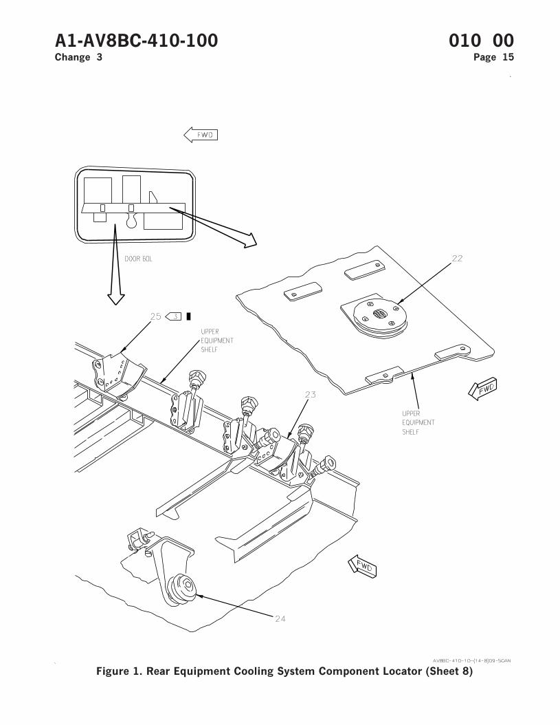
Figure 1. Rear Equipment Cooling System Component Locator (Sheet 8)
A1-AV8BC-410-100 010 00Change 3 Page 15
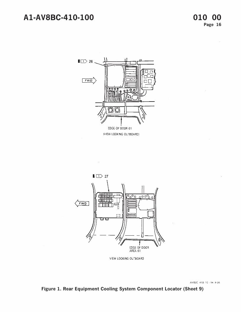
Figure 1. Rear Equipment Cooling System Component Locator (Sheet 9)
A1-AV8BC-410-100 010 00Page 16
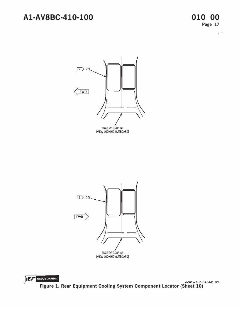
Figure 1. Rear Equipment Cooling System Component Locator (Sheet 10)
A1-AV8BC-410-100 010 00Page 17
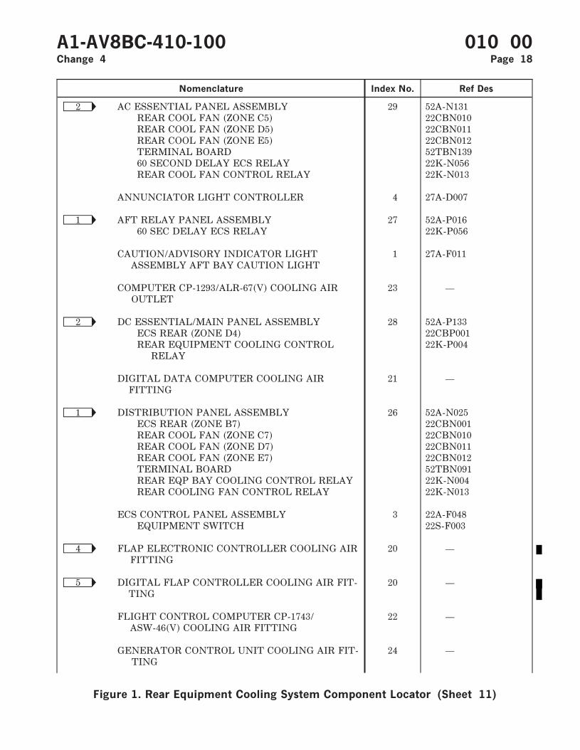
Nomenclature Index No. Ref Des
Ñ2 AC ESSENTIAL PANEL ASSEMBLY 29 52A-N131REAR COOL FAN (ZONE C5) 22CBN010REAR COOL FAN (ZONE D5) 22CBN011REAR COOL FAN (ZONE E5) 22CBN012TERMINAL BOARD 52TBN13960 SECOND DELAY ECS RELAY 22K-N056REAR COOL FAN CONTROL RELAY 22K-N013
ANNUNCIATOR LIGHT CONTROLLER 4 27A-D007
Ñ1 AFT RELAY PANEL ASSEMBLY 27 52A-P01660 SEC DELAY ECS RELAY 22K-P056
CAUTION/ADVISORY INDICATOR LIGHTASSEMBLY AFT BAY CAUTION LIGHT
1 27A-F011
COMPUTER CP-1293/ALR-67(V) COOLING AIROUTLET
23 —
Ñ2 DC ESSENTIAL/MAIN PANEL ASSEMBLY 28 52A-P133ECS REAR (ZONE D4) 22CBP001REAR EQUIPMENT COOLING CONTROL
RELAY22K-P004
DIGITAL DATA COMPUTER COOLING AIRFITTING
21 —
Ñ1 DISTRIBUTION PANEL ASSEMBLY 26 52A-N025ECS REAR (ZONE B7) 22CBN001REAR COOL FAN (ZONE C7) 22CBN010REAR COOL FAN (ZONE D7) 22CBN011REAR COOL FAN (ZONE E7) 22CBN012TERMINAL BOARD 52TBN091REAR EQP BAY COOLING CONTROL RELAY 22K-N004REAR COOLING FAN CONTROL RELAY 22K-N013
ECS CONTROL PANEL ASSEMBLY 3 22A-F048EQUIPMENT SWITCH 22S-F003
Ñ4 FLAP ELECTRONIC CONTROLLER COOLING AIRFITTING
20 —
Ñ5 DIGITAL FLAP CONTROLLER COOLING AIR FIT-TING
20 —
FLIGHT CONTROL COMPUTER CP-1743/ASW-46(V) COOLING AIR FITTING
22 —
GENERATOR CONTROL UNIT COOLING AIR FIT-TING
24 —
A1-AV8BC-410-100 010 00Change 4 Page 18
Figure 1. Rear Equipment Cooling System Component Locator (Sheet 11)
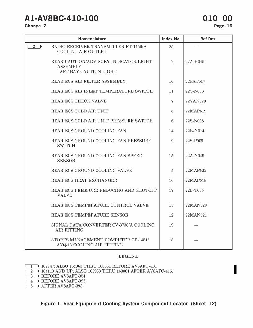
Nomenclature Index No. Ref Des
Ñ3 RADIO-RECEIVER TRANSMITTER RT-1159/ACOOLING AIR OUTLET
25 —
REAR CAUTION/ADVISORY INDICATOR LIGHTASSEMBLY
2 27A-H045
AFT BAY CAUTION LIGHT
REAR ECS AIR FILTER ASSEMBLY 16 22FAT517
REAR ECS AIR INLET TEMPERATURE SWITCH 11 22S-N006
REAR ECS CHECK VALVE 7 22VAN523
REAR ECS COLD AIR UNIT 8 22MAP519
REAR ECS COLD AIR UNIT PRESSURE SWITCH 6 22S-N008
REAR ECS GROUND COOLING FAN 14 22B-N014
REAR ECS GROUND COOLING FAN PRESSURESWITCH
9 22S-P009
REAR ECS GROUND COOLING FAN SPEEDSENSOR
15 22A-N049
REAR ECS GROUND COOLING VALVE 5 22MAP522
REAR ECS HEAT EXCHANGER 10 22MAP518
REAR ECS PRESSURE REDUCING AND SHUTOFFVALVE
17 22L-T005
REAR ECS TEMPERATURE CONTROL VALVE 13 22MAN520
REAR ECS TEMPERATURE SENSOR 12 22MAN521
SIGNAL DATA CONVERTER CV-3736/A COOLINGAIR FITTING
19 —
STORES MANAGEMENT COMPUTER CP-1451/AYQ-13 COOLING AIR FITTING
18 —
LEGEND
Ñ1 162747; ALSO 162963 THRU 163861 BEFORE AV8AFC-416.Ñ2 164113 AND UP; ALSO 162963 THRU 163861 AFTER AV8AFC-416.Ñ3 BEFORE AV8AFC-354.Ñ4 BEFORE AV8AFC-393.Ñ5 AFTER AV8AFC-393.
A1-AV8BC-410-100 010 00Change 7 Page 19
Figure 1. Rear Equipment Cooling System Component Locator (Sheet 12)

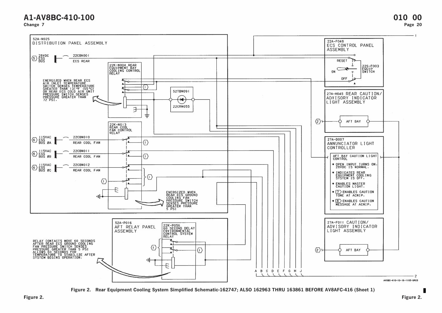
Figure 2. Rear Equipment Cooling System Simplified Schematic-162747; ALSO 162963 THRU 163861 BEFORE AV8AFC-416 (Sheet 1)
A1-AV8BC-410-100 010 00Change 7 Page 20
Figure 2. Figure 2.
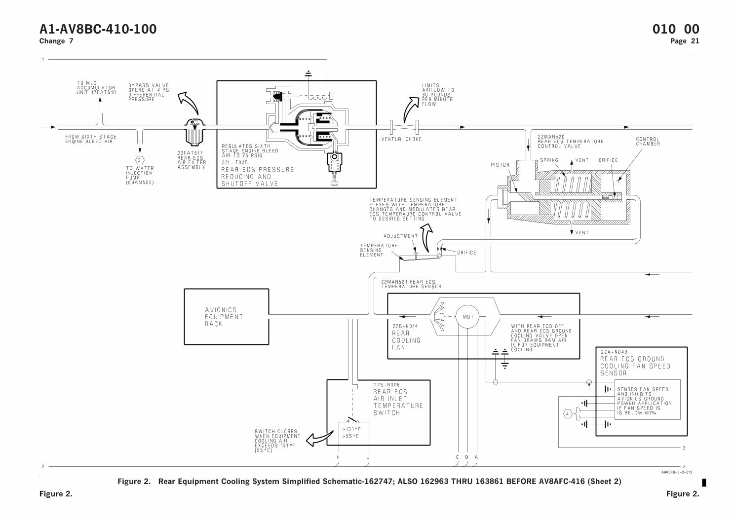
Figure 2. Rear Equipment Cooling System Simplified Schematic-162747; ALSO 162963 THRU 163861 BEFORE AV8AFC-416 (Sheet 2)
A1-AV8BC-410-100 010 00Change 7 Page 21
Figure 2. Figure 2.

Figure 2. Rear Equipment Cooling System Simplified Schematic-162747; ALSO 162963 THRU 163861 BEFORE AV8AFC-416 (Sheet 3)
A1-AV8BC-410-100 010 00Change 7 Page 22
Figure 2. Figure 2.
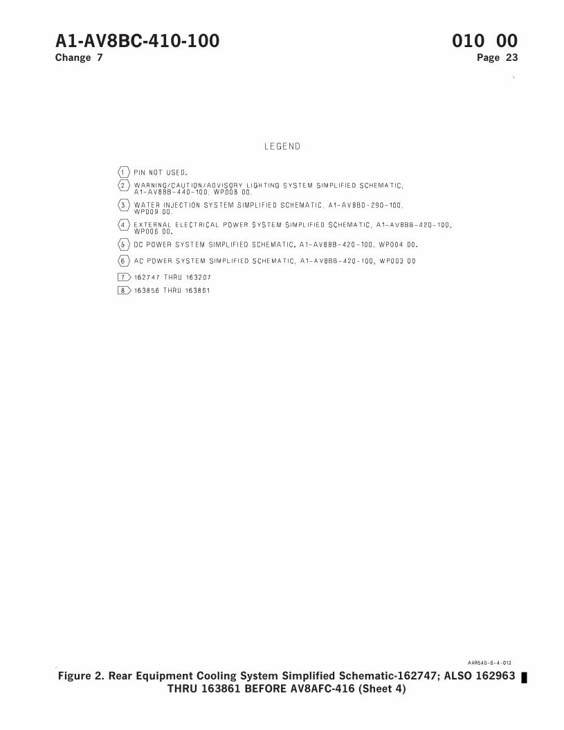
Figure 2. Rear Equipment Cooling System Simplified Schematic-162747; ALSO 162963THRU 163861 BEFORE AV8AFC-416 (Sheet 4)
A1-AV8BC-410-100 010 00Change 7 Page 23

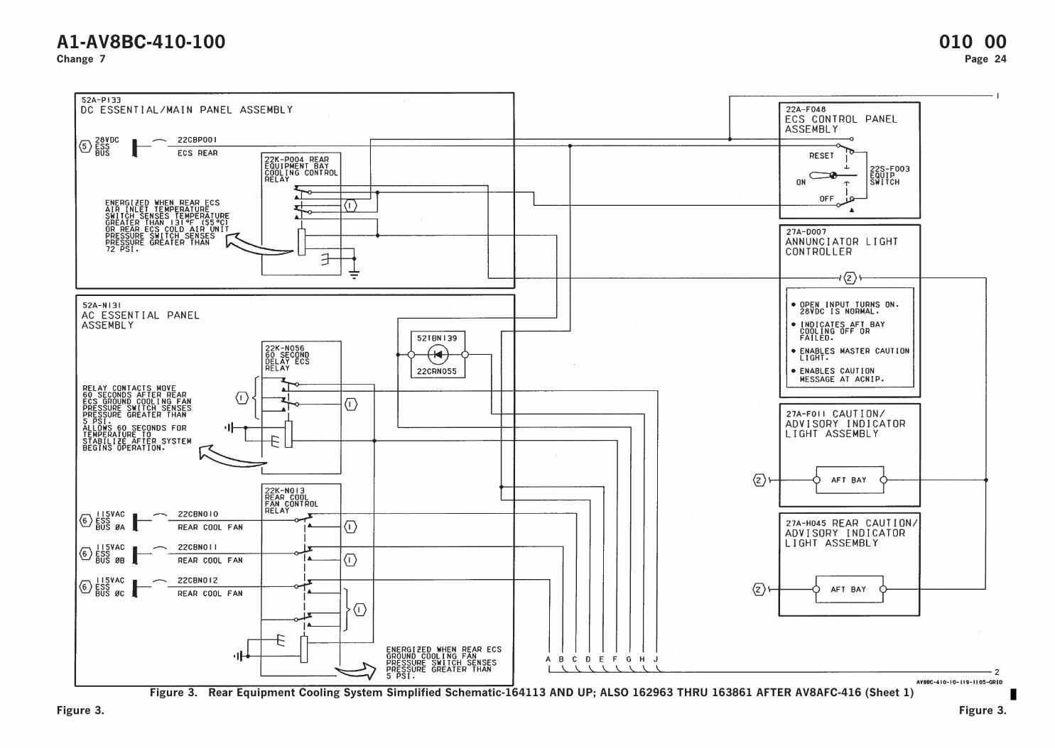
Figure 3. Rear Equipment Cooling System Simplified Schematic-164113 AND UP; ALSO 162963 THRU 163861 AFTER AV8AFC-416 (Sheet 1)
A1-AV8BC-410-100 010 00Change 7 Page 24
Figure 3. Figure 3.
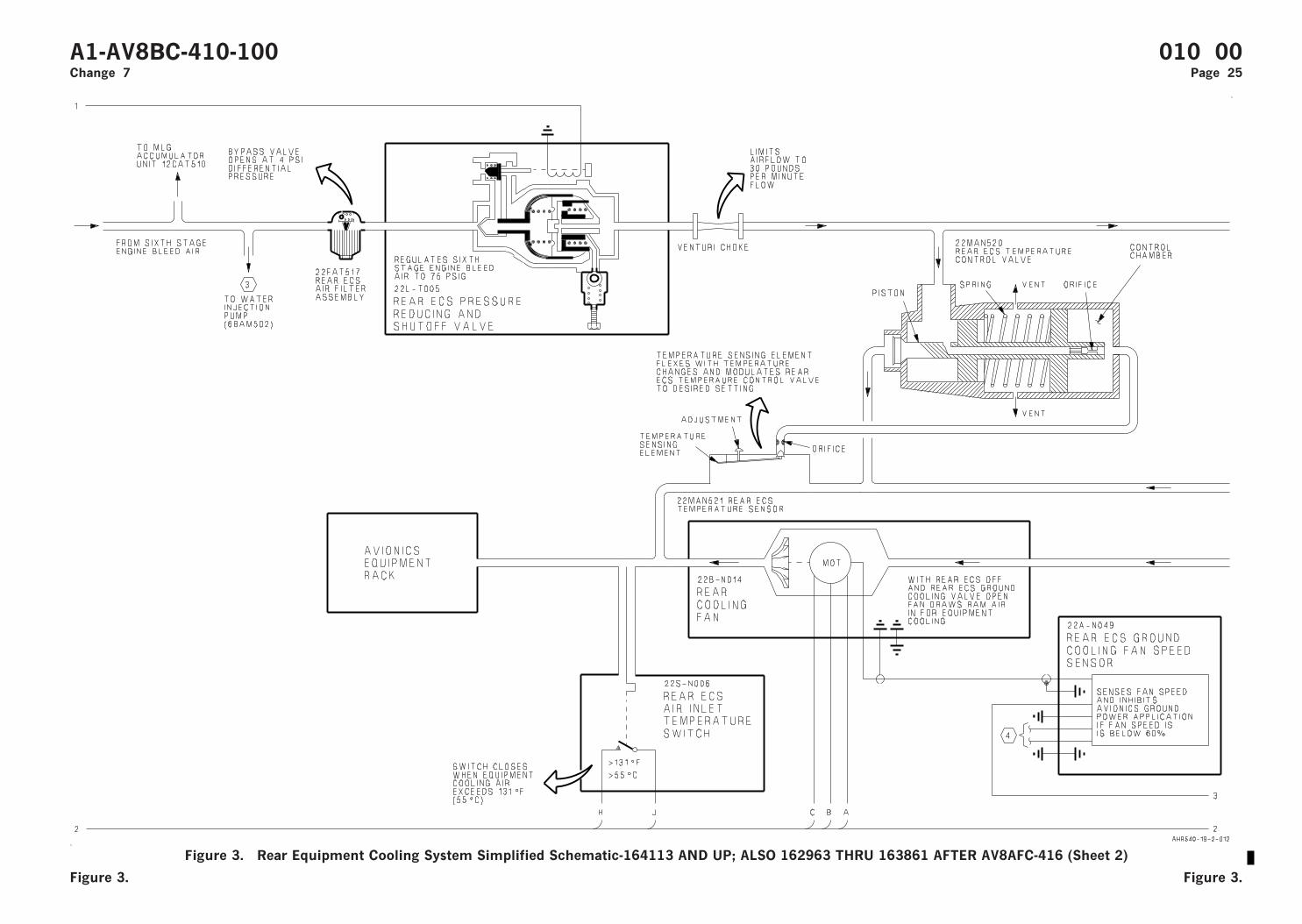
Figure 3. Rear Equipment Cooling System Simplified Schematic-164113 AND UP; ALSO 162963 THRU 163861 AFTER AV8AFC-416 (Sheet 2)
A1-AV8BC-410-100 010 00Change 7 Page 25
Figure 3. Figure 3.
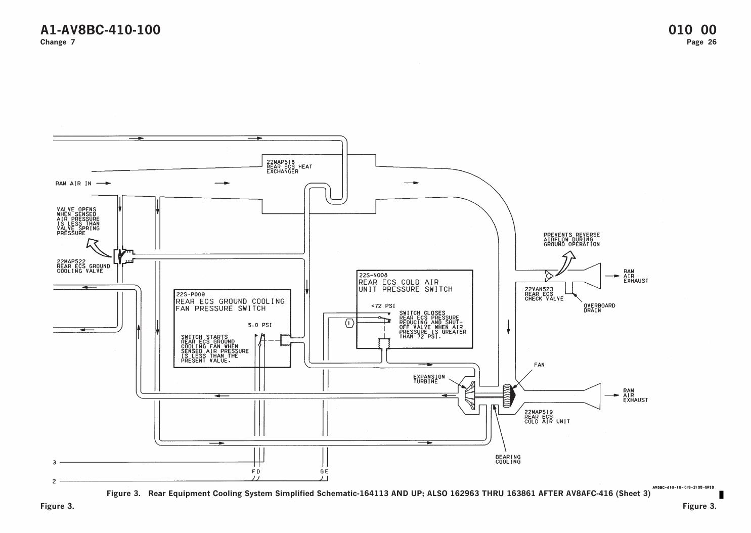
Figure 3. Rear Equipment Cooling System Simplified Schematic-164113 AND UP; ALSO 162963 THRU 163861 AFTER AV8AFC-416 (Sheet 3)
A1-AV8BC-410-100 010 00Change 7 Page 26
Figure 3. Figure 3.
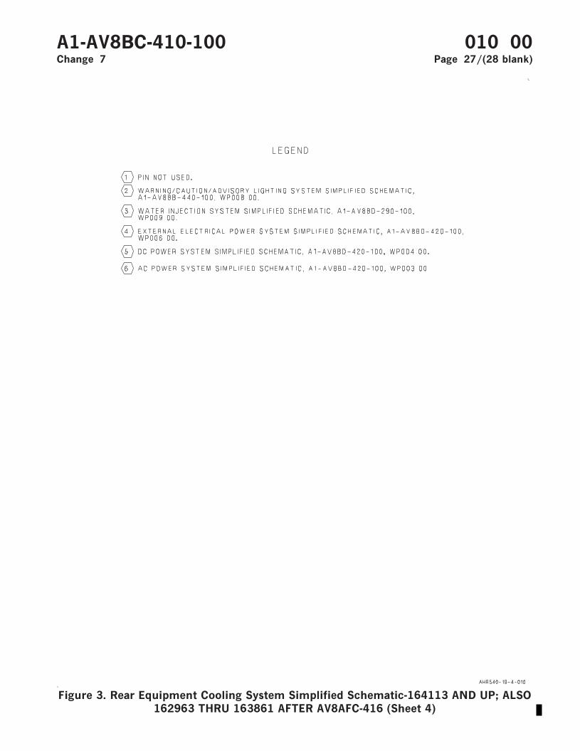
Figure 3. Rear Equipment Cooling System Simplified Schematic-164113 AND UP; ALSO162963 THRU 163861 AFTER AV8AFC-416 (Sheet 4)
A1-AV8BC-410-100 010 00Change 7 Page 27/(28 blank)

ORGANIZATIONAL MAINTENANCE
PRINCIPLES OF OPERATION
DESCRIPTION AND OPERATION
ON-BOARD OXYGEN GENERATING SYSTEM
Reference Material
Ejection Seat and Canopy System ................................................................................. A1-AV8BB-120-100Description - Ejection Seat System ....................................................................... WP003 00
Environmental Control System ...................................................................................... A1-AV8BC-410-100Component Locator - On-Board Oxygen Generating System............................ WP012 00
Power Plant and Related Systems ................................................................................. A1-AV8BD-290-100Basic Engine .............................................................................................................. WP003 00
Electrical Systems............................................................................................................. A1-AV8BB-420-100DC Power System ..................................................................................................... WP004 00
Electrical Systems............................................................................................................. A1-AV8BD-420-100DC Power System WP004 00
Lighting Systems............................................................................................................... A1-AV8BB-440-100Warning/Caution/Advisory Lighting System........................................................ WP007 00
Alphabetical Index
Subject Page No.
Description ................................................................................................................................................... 2Component Description...................................................................................................................... 3
Mixer/Diffuser Duct ................................................................................................................... 3OBOGS Bleed Air Shutoff Valve.............................................................................................. 3OBOGS Heat Exchanger............................................................................................................ 3OBOGS Heat Exchanger Ejector Filter................................................................................... 3OBOGS Overtemperature Switch............................................................................................. 3OBOGS Pressure Relief Valve .................................................................................................. 3OBOGS Test Port ....................................................................................................................... 3Oxygen Concentrator GGU-7/A................................................................................................ 3Oxygen Disconnect...................................................................................................................... 3Oxygen Monitor Assembly CRU-91/A ..................................................................................... 3Oxygen Monitor Assembly CRU-99/A ..................................................................................... 3Oxygen Plenum ........................................................................................................................... 3Rear Oxygen Disconnect ............................................................................................................ 3Rear Oxygen Plenum.................................................................................................................. 3
Related Systems .................................................................................................................................. 3Basic Engine ................................................................................................................................ 3
A1-AV8BC-410-100 011 00Change 7 - 15 May 2004 Page 1
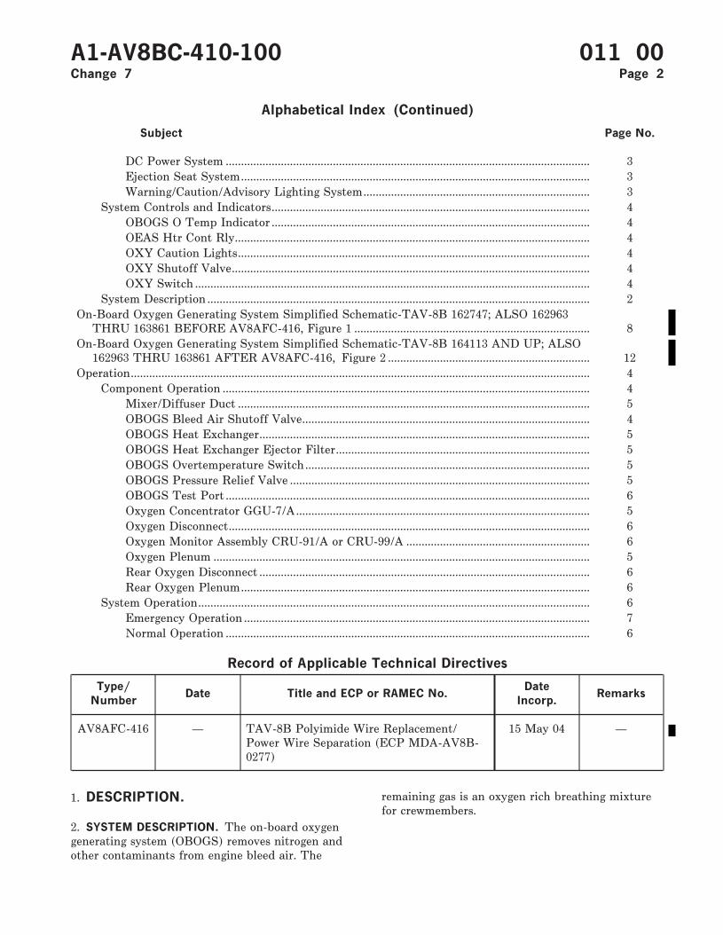
Alphabetical Index (Continued)
Subject Page No.
DC Power System ....................................................................................................................... 3Ejection Seat System.................................................................................................................. 3Warning/Caution/Advisory Lighting System.......................................................................... 3
System Controls and Indicators........................................................................................................ 4OBOGS O Temp Indicator ........................................................................................................ 4OEAS Htr Cont Rly.................................................................................................................... 4OXY Caution Lights................................................................................................................... 4OXY Shutoff Valve..................................................................................................................... 4OXY Switch ................................................................................................................................. 4
System Description ............................................................................................................................. 2On-Board Oxygen Generating System Simplified Schematic-TAV-8B 162747; ALSO 162963
THRU 163861 BEFORE AV8AFC-416, Figure 1 ............................................................................. 8On-Board Oxygen Generating System Simplified Schematic-TAV-8B 164113 AND UP; ALSO
162963 THRU 163861 AFTER AV8AFC-416, Figure 2 .................................................................. 12Operation...................................................................................................................................................... 4
Component Operation ........................................................................................................................ 4Mixer/Diffuser Duct ................................................................................................................... 5OBOGS Bleed Air Shutoff Valve.............................................................................................. 4OBOGS Heat Exchanger............................................................................................................ 5OBOGS Heat Exchanger Ejector Filter................................................................................... 5OBOGS Overtemperature Switch............................................................................................. 5OBOGS Pressure Relief Valve .................................................................................................. 5OBOGS Test Port ....................................................................................................................... 6Oxygen Concentrator GGU-7/A................................................................................................ 5Oxygen Disconnect...................................................................................................................... 6Oxygen Monitor Assembly CRU-91/A or CRU-99/A ............................................................ 6Oxygen Plenum ........................................................................................................................... 5Rear Oxygen Disconnect ............................................................................................................ 6Rear Oxygen Plenum.................................................................................................................. 6
System Operation................................................................................................................................ 6Emergency Operation ................................................................................................................. 7Normal Operation ....................................................................................................................... 6
Record of Applicable Technical Directives
Type/
NumberDate Title and ECP or RAMEC No.
Date
Incorp.Remarks
AV8AFC-416 — TAV-8B Polyimide Wire Replacement/Power Wire Separation (ECP MDA-AV8B-0277)
15 May 04 —
1. DESCRIPTION.
2. SYSTEM DESCRIPTION. The on-board oxygengenerating system (OBOGS) removes nitrogen andother contaminants from engine bleed air. The
remaining gas is an oxygen rich breathing mixturefor crewmembers.
A1-AV8BC-410-100 011 00Change 7 Page 2
3. COMPONENT DESCRIPTION. Systemcomponents are described and listed in paragraphsbelow. For component locator, refer to WP012 00.
4. OBOGS Bleed Air Shutoff Valve. The OBOGSbleed air shutoff valve is a motor driven, butterflytype shutoff valve. The valve is made up of anactuator, electric drive motor, limit switches, ahousing, and an external position indicator.
5. OBOGS Heat Exchanger. The OBOGS heatexchanger is a cross-flow air to air heat exchanger.The heat exchanger is made up of a tubular core,ejector, and ejector filter enclosed in a stainlesssteel case. The heat exchanger case is wrapped withinsulation.
6. OBOGS Heat Exchanger Ejector Filter. TheOBOGS heat exchanger ejector filter is an in-linewire mesh filter. The filter element is brazed to athreaded cap. The filter can be cleaned andreplaced independent of the OBOGS heatexchanger.
7. Mixer/Diffuser Duct. The mixer/diffuser duct isa stainless steel machined duct.
8. OBOGS Pressure Relief Valve. The OBOGSpressure relief valve is an in-line, mechanical,pressure relief valve.
9. OBOGS Overtemperature Switch. The OBOGSovertemperature switch is a sealed, bi-metallicelectrical switch designed into a threaded plug forin-line mounting.
10. Oxygen Concentrator GGU-7/A. The oxygenconcentrator GGU-7/A is an electrical/mechanicaldevice. The concentrator is made up of a rotaryvalve, two molecular sieve beds, drive/servo motor,temperature control circuit, plenum assembly, airheater, inlet filter, pressure reducer, and aninsulating shroud.
11. Oxygen Plenum. The oxygen plenum is anin-line, 100 cubic inch, aluminum storage cylinder.
12. Rear Oxygen Plenum. The rear oxygen plenumis an in-line, 100 cubic inch, aluminum storagecylinder.
13. Oxygen Monitor Assembly CRU-91/A. Theoxygen monitor assembly CRU-91/A is an electronicprocessor. The monitor is made up of an oxygen
sensor, processing electronics, built-in test (BIT), acircuit heater and a pressure controlled sensingchamber.
14. Oxygen Monitor Assembly CRU-99/A. Theoxygen monitor assembly CRU-99/A is a solid stateelectronic processor. The monitor is made up ofprocessing electronics, two built-in test (BIT)buttons, a circuit heater and a pressure controlledsensing chamber.
15. Oxygen Disconnect. The oxygen disconnect isa console mounted, quick release disconnect.
16. Rear Oxygen Disconnect. The rear oxygendisconnect is a console mounted, quick releasedisconnect.
17. OBOGS Test Port. The OBOGS test port is anin-line, capped, tee fitting.
18. RELATED SYSTEMS. Related systems aredescribed in paragraphs below.
19. Ejection Seat System. The ejection seats(A1-AV8BB-120-100, WP003 00) have anemergency oxygen cylinder stored in each survivalkit. The emergency oxygen supply can be manuallyactuated if OBOGS is off or fails, or automaticallyactuated during emergency egress.
20. Basic Engine. The engine (A1-AV8BD-290-100,WP003 00) provides hot, eighth stage compressorbleed air to the on-board oxygen generating system.
21. DC Power System. The DC power system on162747; ALSO 162963 THRU 163861 BEFOREAV8AFC-416 (A1-AV8BB-420-100, WP004 00) or164113 AND UP; ALSO 162963 THRU 163861AFTER AV8AFC-416 (A1-AV8BD-420-100, WP00400) provides emergency and main 28vdc power tothe on-board oxygen generating system.
22. Warning/Caution/Advisory Lighting System.
The warning/caution/advisory lighting system(A1-AV8BB-440-100, WP007 00) provides visualindication of normal aircraft functions and systemmalfunctions affecting safety of flight operations.The warning/caution/advisory lighting systemincludes the annunciator light controller and thecaution/advisory indicator light assembly. Theannunciator light controller receives data fromvarious aircraft systems and provides logic to turnon and off warning/caution/advisory lights.
A1-AV8BC-410-100 011 00Change 7 Page 3
23. The annunciator light controller will turn onthe OXY caution lights and the MASTERCAUTION lights when the oxygen monitorassembly senses that oxygen concentration hasfallen below a safe minimum or the OBOGSovertemperature switch senses temperature greaterthan 250°F (121oC).
24. SYSTEM CONTROLS AND INDICATORS.
System controls and indicators are described inparagraphs below.
25. OXY Switch. The OXY switch, located on thepilot services panel assembly, is a two pole, doublethrow, lever lock toggle switch. The switch has twopositions; OFF and OXY. The switch is locked inthe OXY position.
26. With the switch in the OFF position, thefollowing occurs:
a. A ground is removed to deenergize the OEAShtr control relay.
b. Emergency 28vdc power is removed from theopen contact of the OBOGS bleed air shutoff valve.
c. Emergency 28vdc power is applied to theclose contact of the OBOGS bleed air shutoff valve.
27. With the switch in the OXY position, thefollowing occurs:
a. A ground is applied to energize the OEAShtr control relay.
b. Emergency 28vdc power is removed from theclose contact of the OBOGS bleed air shutoff valve.
c. Emergency 28vdc power is applied to theopen contact of the OBOGS bleed air shutoff valve.
28. OBOGS O Temp Indicator. The OBOGS OTEMP indicator, located on the oxygenconcentrator shelf, is a fault locating, flag indicatingmechanical reset indicator. The indicator provides avisual indication when oxygen concentrator inlettemperature exceeds 250°F (121oC).
29. When oxygen concentrator GGU-7/A inlettemperature exceeds 250°F (121oC), the OBOGSovertemperature switch closes and provides aground to allow main 28vdc power to be applied tothe indicator coil. The coil trips the indicator fromthe normal, all black indication to the fault locating,
black and white flag indication. The indicator ismechanically reset by pressing the indicator face.
30. OXY Caution Lights. The OXY caution lights,located on the caution/advisory indicator lightassembly, and rear caution/advisory indicator lightassembly, are dual lamp, indicator lights.
31. The OXY caution lights are controlled by theoxygen monitor assembly or OBOGSovertemperature switch, through thewarning/caution/advisory lighting system.
32. OEAS Htr Control Relay. The OEAS htrcontrol relay, located on the distribution panelassembly, is a two pole, double throw, 10 amperes,permanent magnet drive, armature relay.
33. The relay is controlled by the OXY switch.With the relay energized, main 28vdc power isapplied to the two heater circuits in the oxygenconcentrator. With the relay deenergized, main28vdc power is removed from the concentratorheater circuits.
34. OXY Shutoff Valve. The OXY shutoff valvelocated on the rear pilot services panel assembly, isan in-line, mechanical, shutoff valve. The valve hastwo positions; ON and OFF.
35. With the OXY shutoff valve set to ON, oxygenis provided to the rear oxygen disconnect.
36. OPERATION.
37. COMPONENT OPERATION.
38. OBOGS Bleed Air Shutoff Valve. The OBOGSbleed air shutoff valve is located in door 11R. Thevalve is electrically controlled and electricallyactuated.
39. The valve is driven open or closed by an electricmotor in response to electrical signals controlled bythe OXY switch. Emergency 28vdc power is appliedto the open or closed contacts. The valve motormoves as required, driving the actuator whichmoves the valve butterfly.
40. The motor has limit switches to prevent valvemotor overrun. When the valve butterfly hasreached its fully open or fully closed limit, theassociated limit switch is mechanically opened andelectrical power is removed from the motor.
A1-AV8BC-410-100 011 00Change 6 Page 4
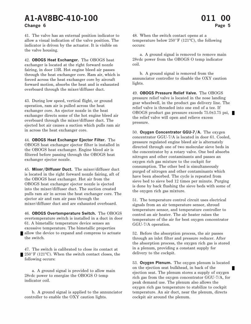
41. The valve has an external position indicator toallow a visual indication of the valve position. Theindicator is driven by the actuator. It is visible onthe valve housing.
42. OBOGS Heat Exchanger. The OBOGS heatexchanger is located at the right forward nozzlefairing, in door 13R. Hot engine bleed air passesthrough the heat exchanger core. Ram air, which isforced across the heat exchanger core by aircraftforward motion, absorbs the heat and is exhaustedoverboard through the mixer/diffuser duct.
43. During low speed, vertical flight, or groundoperation, ram air is pulled across the heatexchanger core. An ejector nozzle in the heatexchanger directs some of the hot engine bleed airoverboard through the mixer/diffuser duct. Theejected hot air causes a suction which pulls ram airin across the heat exchanger core.
44. OBOGS Heat Exchanger Ejector Filter. TheOBOGS heat exchanger ejector filter is installed inthe OBOGS heat exchanger. Engine bleed air isfiltered before passing through the OBOGS heatexchanger ejector nozzle.
45. Mixer/Diffuser Duct. The mixer/diffuser ductis located in the right forward nozzle fairing, aft ofthe OBOGS heat exchanger. Hot air from theOBOGS heat exchanger ejector nozzle is ejectedinto the mixer/diffuser duct. The suction createdpulls ram air in across the heat exchanger core. Theejector air and ram air pass through themixer/diffuser duct and are exhausted overboard.
46. OBOGS Overtemperature Switch. The OBOGSovertemperature switch is installed in a duct in door61. A bimetallic temperature device senses anexcessive temperature. The bimetallic propertiesallow the device to expand and compress to actuatethe switch.
47. The switch is calibrated to close its contact at250°F (121oC). When the switch contact closes, thefollowing occurs:
a. A ground signal is provided to allow main28vdc power to energize the OBOGS O tempindicator coil.
b. A ground signal is applied to the annunciatorcontroller to enable the OXY caution lights.
48. When the switch contact opens at atemperature below 250°F (121oC), the followingoccurs:
a. A ground signal is removed to remove main28vdc power from the OBOGS O temp indicatorcoil.
b. A ground signal is removed from theannunciator controller to disable the OXY cautionlights.
49. OBOGS Pressure Relief Valve. The OBOGSpressure relief valve is located in the nose landinggear wheelwell, in the product gas delivery line. Therelief valve is threaded into one end of a tee. IfOBOGS product gas pressure exceeds 75.0±3.75 psi,the relief valve will open and relieve excesspressure.
50. Oxygen Concentrator GGU-7/A. The oxygenconcentrator GGU-7/A is located in door 61. Cooled,pressure regulated engine bleed air is alternatelydirected through one of two molecular sieve beds inthe concentrator by a rotary valve. One bed absorbsnitrogen and other contaminants and passes anoxygen rich gas mixture to the cockpit forconsumption. The other bed is simultaneouslypurged of nitrogen and other contaminants whichhave been absorbed. The cycle is repeated fromsieve bed to sieve bed 12 times per minute. Purgingis done by back flushing the sieve beds with some ofthe oxygen rich gas mixture.
51. The temperature control circuit uses electricalsignals from an air temperature sensor, shroudtemperature sensor, and temperature controller tocontrol an air heater. The air heater raises thetemperature of the air for best oxygen concentratorGGU-7/A operation.
52. Before the absorption process, the air passesthrough an inlet filter and pressure reducer. Afterthe absorption process, the oxygen rich gas is storedin a plenum, providing a constant supply fordelivery to the cockpit.
53. Oxygen Plenum. The oxygen plenum is locatedon the ejection seat bulkhead, in back of theejection seat. The plenum stores a supply of oxygenrich gas from the oxygen concentrator GGU-7/A, forpeak demand use. The plenum also allows theoxygen rich gas temperature to stabilize to cockpittemperature. An air duct, near the plenum, directscockpit air around the plenum.
A1-AV8BC-410-100 011 00Change 6 Page 5
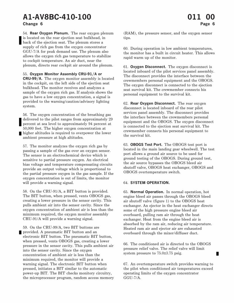
54. Rear Oxygen Plenum. The rear oxygen plenumis located on the rear ejection seat bulkhead, inback of the ejection seat. The plenum stores asupply of rich gas from the oxygen concentratorGGU-7/A for peak demand use. The plenum alsoallows the oxygen rich gas temperature to stabilizeto cockpit temperature. An air duct, near theplenum, directs rear cockpit air around the plenum.
55. Oxygen Monitor Assembly CRU-91/A or
CRU-99/A. The oxygen monitor assembly is locatedin the cockpit, on the left side of the ejection seatbulkhead. The monitor receives and analyzes asample of the oxygen rich gas. If analysis shows thegas to have a low oxygen concentration, a signal isprovided to the warning/caution/advisory lightingsystem.
56. The oxygen concentration of the breathing gasdelivered to the pilot ranges from approximately 29percent at sea level to approximately 94 percent at50,000 feet. The higher oxygen concentration athigher altitudes is required to overpower the lowerambient pressure at high altitudes.
57. The monitor analyzes the oxygen rich gas bypassing a sample of the gas over an oxygen sensor.The sensor is an electrochemical device which issensitive to partial pressure oxygen. An electricalbias voltage and temperature compensating circuitsprovide an output voltage which is proportional tothe partial pressure oxygen in the gas sample. If theoxygen concentration is out of limits, the monitorwill provide a warning signal.
58. On the CRU-91/A, a BIT button is provided.The BIT button, when pressed, vents OBOGS gas,creating a lower pressure in the sensor cavity. Thispulls ambient air into the sensor cavity. Since theoxygen concentration of ambient air is less than theminimum required, the oxygen monitor assemblyCRU-91/A will provide a warning signal.
59. On the CRU-99/A, two BIT buttons areprovided. A pneumatic BIT button and anelectronic BIT button. The pneumatic BIT button,when pressed, vents OBOGS gas, creating a lowerpressure in the sensor cavity. This pulls ambient airinto the sensor cavity. Since the oxygenconcentration of ambient air is less than theminimum required, the monitor will provide awarning signal. The electronic BIT button whenpressed, initiates a BIT similar to the automaticpower-up BIT. The BIT checks monitory circuitry,the microprocessor program, random access memory
(RAM), the pressure sensor, and the oxygen sensortips.
60. During operation in low ambient temperatures,the monitor has a built in circuit heater. This allowsrapid warm up of the monitor.
61. Oxygen Disconnect. The oxygen disconnect islocated inboard of the pilot services panel assembly.The disconnect provides the interface between thecrewmembers personal equipment and the OBOGS.The oxygen disconnect is connected to the ejectionseat survival kit. The crewmember connects hispersonal equipment to the survival kit.
62. Rear Oxygen Disconnect. The rear oxygendisconnect is located inboard of the rear pilotservices panel assembly. The disconnect providesthe interface between the crewmembers personalequipment and the OBOGS. The oxygen disconnectis connected to the ejection seat survival kit. Thecrewmember connects his personal equipment tothe survival kit.
63. OBOGS Test Port. The OBOGS test port islocated in the main landing gear wheelwell. The testport allows a ground air source to be used forground testing of the OBOGS. During ground test,the air source bypasses the OBOGS bleed airshutoff valve, OBOGS heat exchanger, OBOGS andOBOGS overtemperature switch.
64. SYSTEM OPERATION.
65. Normal Operation. In normal operation, hotengine bleed air passes through the OBOGS bleedair shutoff valve (figure 1) to the OBOGS heatexchanger. An ejector in the heat exchanger directssome of the high pressure engine bleed airoverboard, pulling ram air through the heatexchanger. Heat from the engine bleed air isabsorbed by the ram air, reducing air temperature.Heated ram air and ejector air are exhaustedoverboard through the mixer/diffuser duct.
66. The conditioned air is directed to the OBOGSpressure relief valve. The relief valve will limitsystem pressure to 75.0±3.75 psig.
67. An overtemperature switch provides warning tothe pilot when conditioned air temperatures exceedoperating limits of the oxygen concentratorGGU-7/A.
A1-AV8BC-410-100 011 00Change 6 Page 6
68. The oxygen concentrator GGU-7/A removesnitrogen and other contaminants from theconditioned air, leaving an oxygen rich breathinggas mixture. Nitrogen and other contaminants arepurged from the concentrator and exhaustedoverboard.
69. The oxygen rich gas mixture is routed to theoxygen plenum in the cockpit and the rear oxygenplenum in the rear cockpit. The plenums store themixture for peak demand periods and providetemperature stabilization. A sample of the mixtureis supplied to the oxygen monitor assembly, whichwarns the pilot if oxygen concentration falls below asafe limit. The breathing gas mixture flows from theoxygen plenum to the oxygen disconnect, inboard ofthe pilot services panel. Breathing gas is thenrouted to the cockpit through the survival kit andtorso mounted oxygen regulator to the crewmember.
70. Breathing gas is routed to the rear cockpitthrough the survival kit and torso mounted oxygenregulator to the crewmember.
71. Emergency Operation. A 15 minute supply ofoxygen is stored in an emergency oxygen cylinder inthe ejection seat survival kit in both the cockpit andrear cockpit (figure 1). The emergency oxygensupply can be activated manually, by pulling themanual emergency oxygen control (green ring), orautomatically on ejection. A check valve preventsloss of oxygen pressure to the OBOGS whenemergency oxygen is actuated.
72. The OBOGS and emergency oxygen are notrelated in any way, except they share a commonmanifold in each ejection seat survival kit.
A1-AV8BC-410-100 011 00Change 6 Page 7

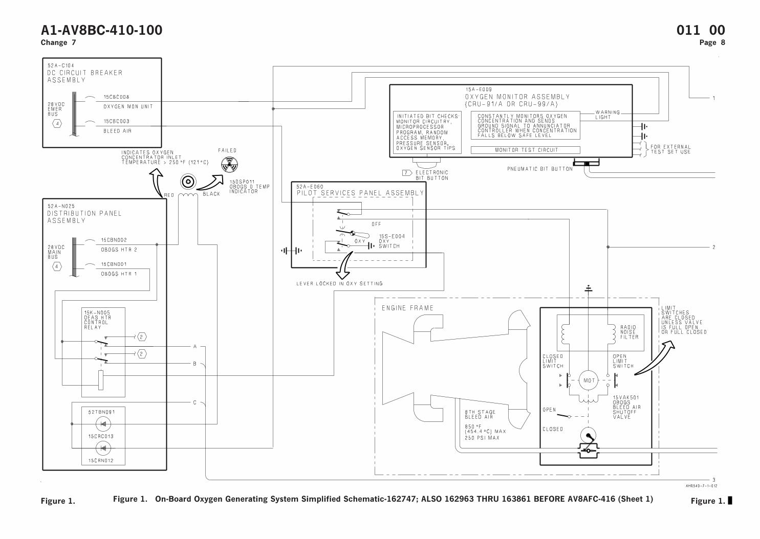
Figure 1. On-Board Oxygen Generating System Simplified Schematic-162747; ALSO 162963 THRU 163861 BEFORE AV8AFC-416 (Sheet 1)
A1-AV8BC-410-100 011 00Change 7 Page 8
Figure 1. Figure 1.
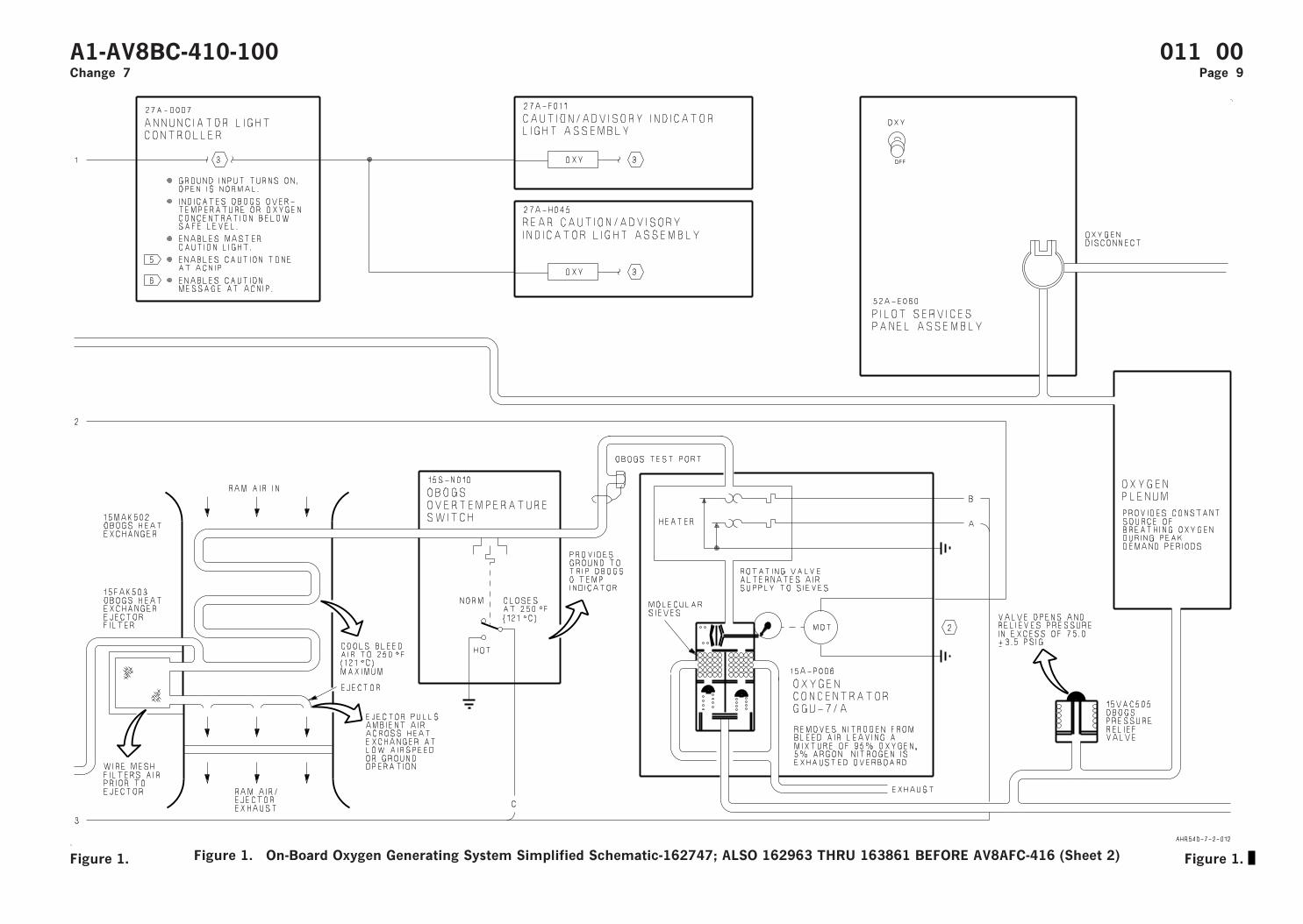
Figure 1. On-Board Oxygen Generating System Simplified Schematic-162747; ALSO 162963 THRU 163861 BEFORE AV8AFC-416 (Sheet 2)
A1-AV8BC-410-100 011 00Change 7 Page 9
Figure 1. Figure 1.

Figure 1. On-Board Oxygen Generating System Simplified Schematic-162747; ALSO 162963 THRU 163861 BEFORE AV8AFC-416 (Sheet 3)
A1-AV8BC-410-100 011 00Change 7 Page 10
Figure 1. Figure 1.
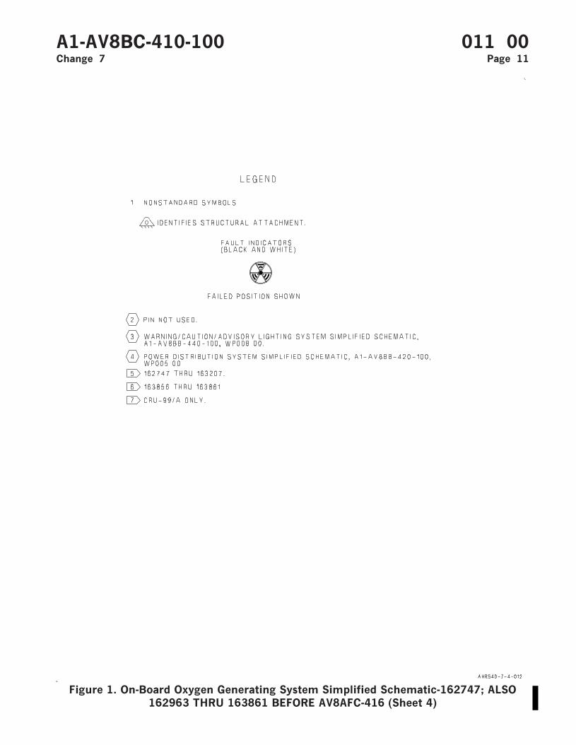
Figure 1. On-Board Oxygen Generating System Simplified Schematic-162747; ALSO162963 THRU 163861 BEFORE AV8AFC-416 (Sheet 4)
A1-AV8BC-410-100 011 00Change 7 Page 11

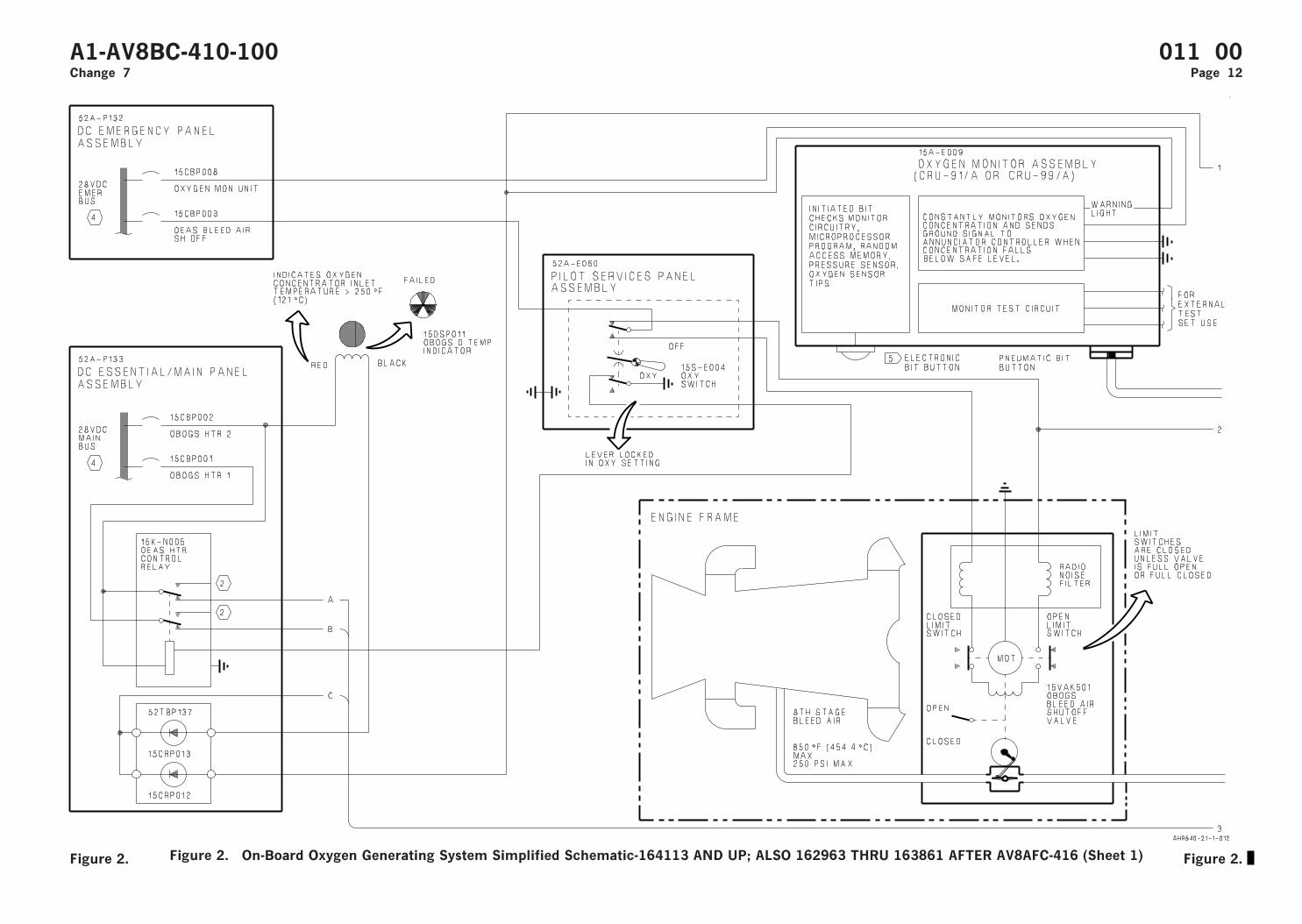
Figure 2. On-Board Oxygen Generating System Simplified Schematic-164113 AND UP; ALSO 162963 THRU 163861 AFTER AV8AFC-416 (Sheet 1)
A1-AV8BC-410-100 011 00Change 7 Page 12
Figure 2. Figure 2.

Figure 2. On-Board Oxygen Generating System Simplified Schematic-164113 AND UP; ALSO 162963 THRU 163861 AFTER AV8AFC-416 (Sheet 2)
A1-AV8BC-410-100 011 00Change 7 Page 13
Figure 2. Figure 2.
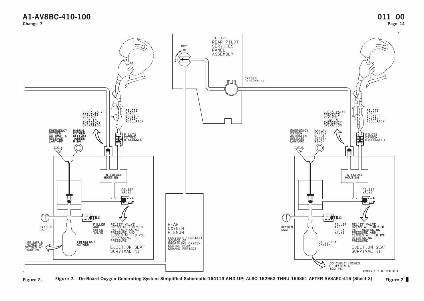
Figure 2. On-Board Oxygen Generating System Simplified Schematic-164113 AND UP; ALSO 162963 THRU 163861 AFTER AV8AFC-416 (Sheet 3)
A1-AV8BC-410-100 011 00Change 7 Page 14
Figure 2. Figure 2.
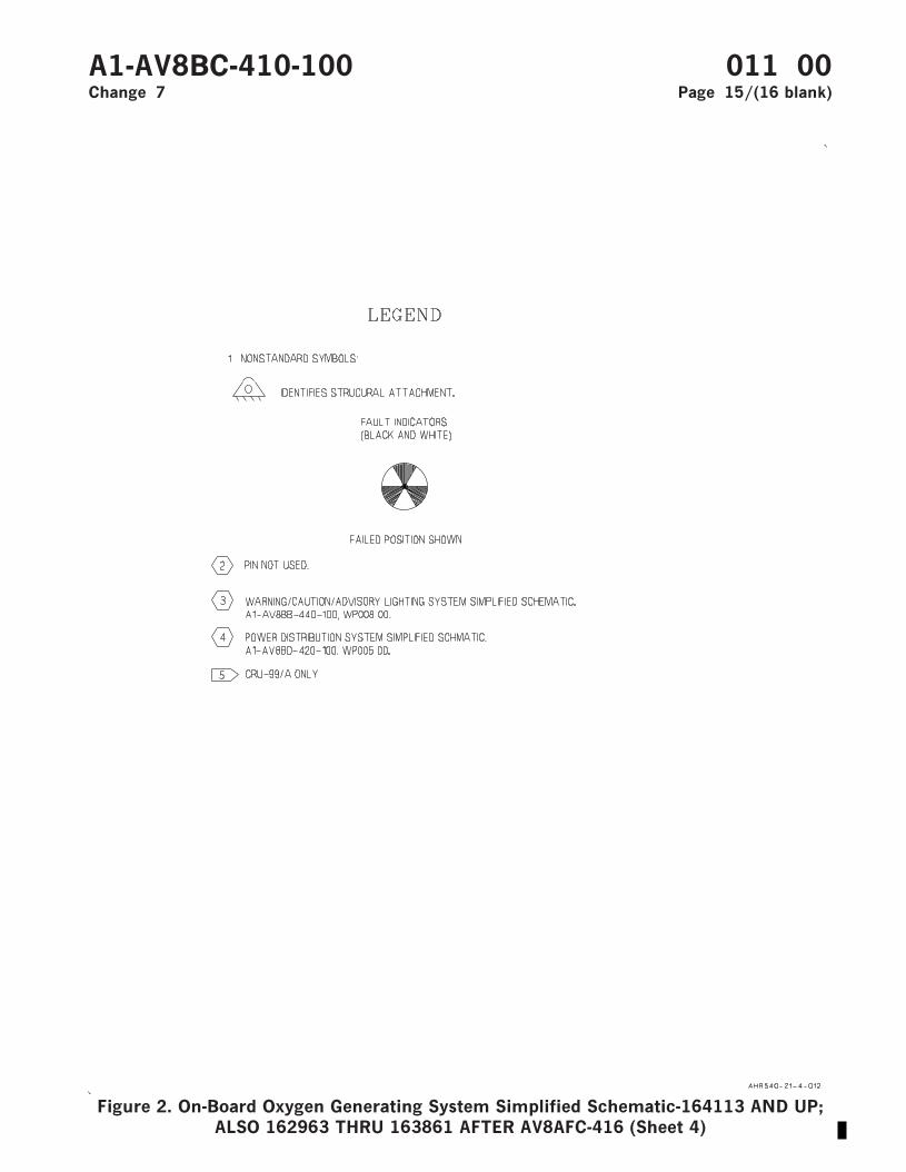
Figure 2. On-Board Oxygen Generating System Simplified Schematic-164113 AND UP;ALSO 162963 THRU 163861 AFTER AV8AFC-416 (Sheet 4)
A1-AV8BC-410-100 011 00Change 7 Page 15/(16 blank)


ORGANIZATIONAL MAINTENANCE
PRINCIPLES OF OPERATION
COMPONENT LOCATOR
ON-BOARD OXYGEN GENERATING SYSTEM
Reference Material
Environmental Control Systems..................................................................................... A1-AV8BC-410-100Description and Operation - On-Board Oxygen Generating System ................ WP011 00
Alphabetical Index
Subject Page No.
On-Board Oxygen Generating System Component Locator, Figure 1 ................................................ 2System Components ................................................................................................................................... 1
Record of Applicable Technical Directives
Type/
NumberDate Title and ECP or RAMEC No.
Date
Incorp.Remarks
AV8AFC-416 — TAV-8B Polyimide Wire Replacement/Power Wire Separation (ECP MDA-AV8B-0277)
15 May 04 —
1. SYSTEM COMPONENTS.
2. System components are shown in figure 1. Fordescription and operation of the On-Board OxygenGenerating System, refer to WP011 00.
A1-AV8BC-410-100 012 00Change 7 - 15 May 2004 Page 1
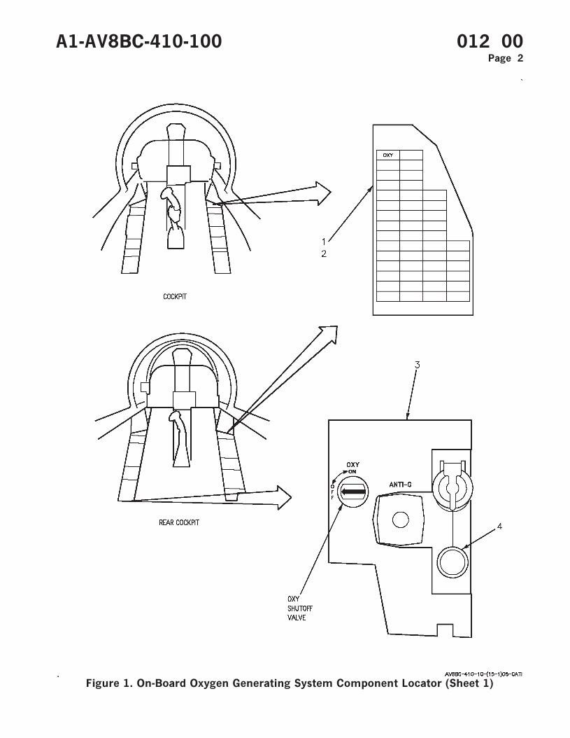
Figure 1. On-Board Oxygen Generating System Component Locator (Sheet 1)
A1-AV8BC-410-100 012 00Page 2
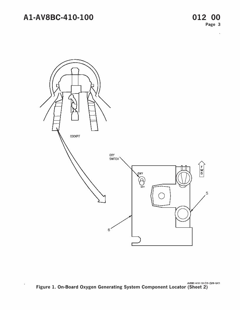
Figure 1. On-Board Oxygen Generating System Component Locator (Sheet 2)
A1-AV8BC-410-100 012 00Page 3
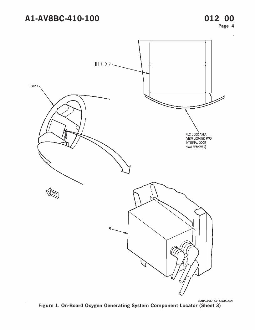
Figure 1. On-Board Oxygen Generating System Component Locator (Sheet 3)
A1-AV8BC-410-100 012 00Page 4
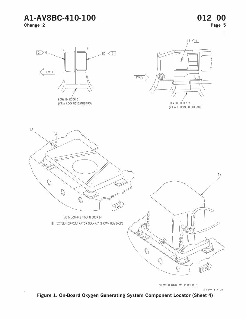
Figure 1. On-Board Oxygen Generating System Component Locator (Sheet 4)
A1-AV8BC-410-100 012 00Change 2 Page 5
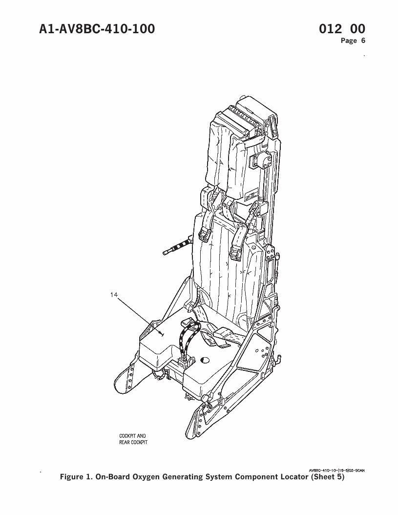
Figure 1. On-Board Oxygen Generating System Component Locator (Sheet 5)
A1-AV8BC-410-100 012 00Page 6
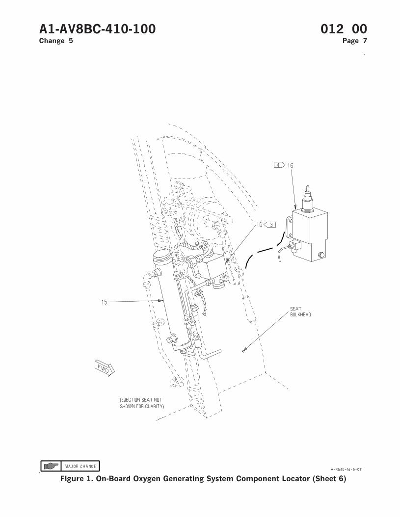
Figure 1. On-Board Oxygen Generating System Component Locator (Sheet 6)
A1-AV8BC-410-100 012 00Change 5 Page 7
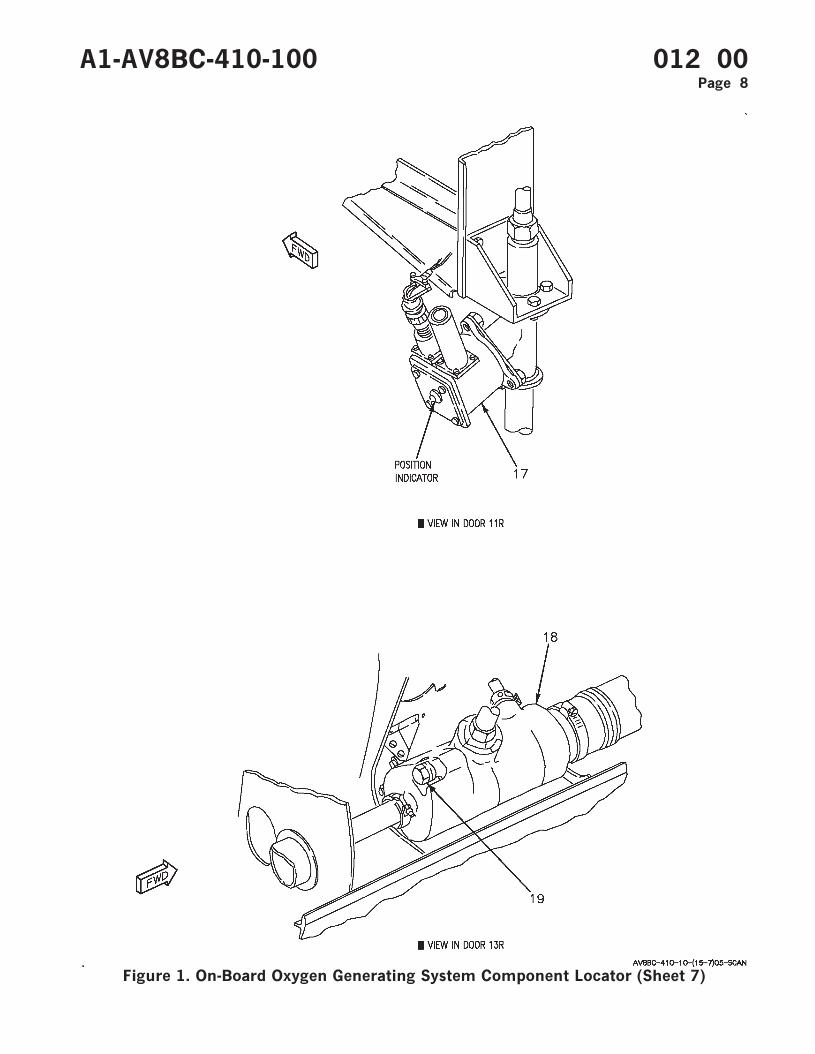
Figure 1. On-Board Oxygen Generating System Component Locator (Sheet 7)
A1-AV8BC-410-100 012 00Page 8
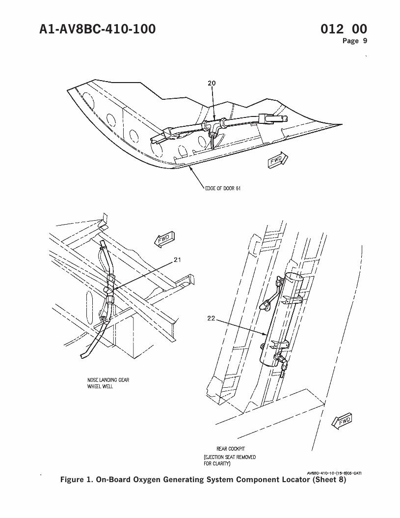
Figure 1. On-Board Oxygen Generating System Component Locator (Sheet 8)
A1-AV8BC-410-100 012 00Page 9
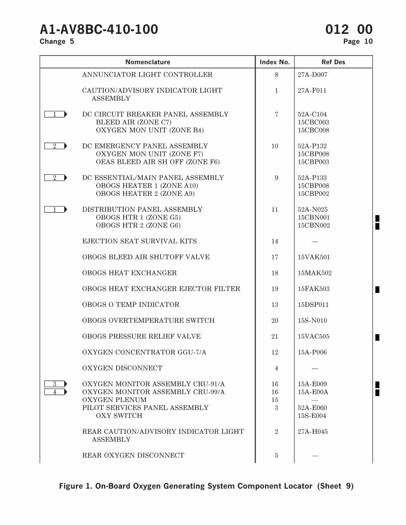
Nomenclature Index No. Ref Des
ANNUNCIATOR LIGHT CONTROLLER 8 27A-D007
CAUTION/ADVISORY INDICATOR LIGHTASSEMBLY
1 27A-F011
Ñ1 DC CIRCUIT BREAKER PANEL ASSEMBLY 7 52A-C104BLEED AIR (ZONE C7) 15CBC003OXYGEN MON UNIT (ZONE B4) 15CBC008
Ñ2 DC EMERGENCY PANEL ASSEMBLY 10 52A-P132OXYGEN MON UNIT (ZONE F7) 15CBP008OEAS BLEED AIR SH OFF (ZONE F6) 15CBP003
Ñ2 DC ESSENTIAL/MAIN PANEL ASSEMBLY 9 52A-P133OBOGS HEATER 1 (ZONE A10) 15CBP008OBOGS HEATER 2 (ZONE A9) 15CBP002
Ñ1 DISTRIBUTION PANEL ASSEMBLY 11 52A-N025OBOGS HTR 1 (ZONE G5) 15CBN001OBOGS HTR 2 (ZONE G6) 15CBN002
EJECTION SEAT SURVIVAL KITS 14 —
OBOGS BLEED AIR SHUTOFF VALVE 17 15VAK501
OBOGS HEAT EXCHANGER 18 15MAK502
OBOGS HEAT EXCHANGER EJECTOR FILTER 19 15FAK503
OBOGS O TEMP INDICATOR 13 15DSP011
OBOGS OVERTEMPERATURE SWITCH 20 15S-N010
OBOGS PRESSURE RELIEF VALVE 21 15VAC505
OXYGEN CONCENTRATOR GGU-7/A 12 15A-P006
OXYGEN DISCONNECT 4 —
Ñ3 OXYGEN MONITOR ASSEMBLY CRU-91/A 16 15A-E009Ñ4 OXYGEN MONITOR ASSEMBLY CRU-99/A 16 15A-E00A
OXYGEN PLENUM 15 —PILOT SERVICES PANEL ASSEMBLY 3 52A-E060
OXY SWITCH 15S-E004
REAR CAUTION/ADVISORY INDICATOR LIGHTASSEMBLY
2 27A-H045
REAR OXYGEN DISCONNECT 5 —
A1-AV8BC-410-100 012 00Change 5 Page 10
Figure 1. On-Board Oxygen Generating System Component Locator (Sheet 9)
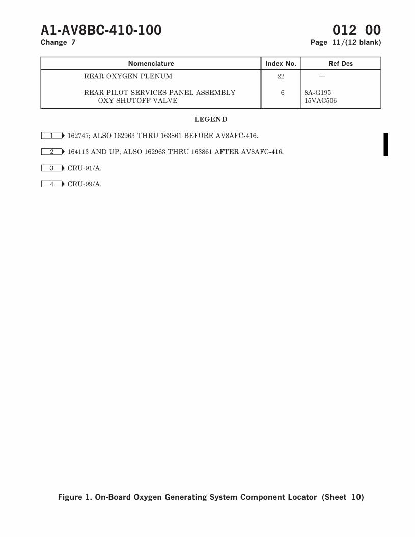
Nomenclature Index No. Ref Des
REAR OXYGEN PLENUM 22 —
REAR PILOT SERVICES PANEL ASSEMBLY 6 8A-G195OXY SHUTOFF VALVE 15VAC506
LEGEND
Ñ1 162747; ALSO 162963 THRU 163861 BEFORE AV8AFC-416.
Ñ2 164113 AND UP; ALSO 162963 THRU 163861 AFTER AV8AFC-416.
Ñ3 CRU-91/A.
Ñ4 CRU-99/A.
A1-AV8BC-410-100 012 00Change 7 Page 11/(12 blank)
Figure 1. On-Board Oxygen Generating System Component Locator (Sheet 10)
