environmental impacts of options for disposal of depleted...
TRANSCRIPT

ANL/EAD/TM-104
Environmental Impacts of Options for Disposal ofDepleted Uranium Tetrafluoride (UF4)
Environmental Assessment DivisionArgonne National Laboratory
Operated by The University of Chicago,under Contract W-31-109-Eng-38, for the
United States Department of Energy

Argonne National LaboratoryArgonne National Laboratory, with facilities in the states of Illinois and Idaho, isowned by the United States Government and operated by The Universityof Chicago under the provisions of a contract with the Department of Energy.
This technical memorandum is a product of Argonne’s Environmental AssessmentDivision (EAD). For information on the division's scientific and engineeringactivities, contact:
Director, Environmental Assessment DivisionArgonne National LaboratoryArgonne, Illinois 60439-4832Telephone (630) 252-3107
Presented in this technical memorandum are preliminary results of ongoing workor work that is more limited in scope and depth than that described in formalreports issued by the EAD.
Publishing support services were provided by Argonne’s Information and Publishing Division (for more information, see IPD’s home page: http://www.ipd.anl.gov/).
DisclaimerThis report was prepared as an account of work sponsored by an agency of theUnited States Government. Neither the United States Government nor any agencythereof, nor The University of Chicago, nor any of their employees or officers,makes any warranty, express or implied, or assumes any legal liability orresponsibility for the accuracy, completeness, or usefulness of any information,apparatus, product, or process disclosed, or represents that its use would notinfringe privately owned rights. Reference herein to any specific commercialproduct, process, or service by trade name, trademark, manufacturer, or otherwisedoes not necessarily constitute or imply its endorsement, recommendation, orfavoring by the United States Government or any agency thereof. The views andopinions of document authors expressed herein do not necessarily state or reflectthose of the United States Government or any agency thereof, Argonne NationalLaboratory, or The University of Chicago.
Available electronically at http://www.doe.gov/bridgeAvailable for a processing fee to U.S. Department ofEnergy and its contractors, in paper, from:U.S. Department of EnergyOffice of Scientific and Technical InformationP.O. Box 62Oak Ridge, TN 37831-0062phone: (865) 576-8401fax: (865) 576-5728email: [email protected]
* Allison and Folga are affiliated with Argonne’s Decision and Information Sciences Division.
ANL/EAD/TM-104
Environmental Impacts of Options for Disposal ofDepleted Uranium Tetrafluoride (UF4)
by F.A. Monette, T. Allison,* H.I. Avci, B.M. Biwer, J.P. Butler, Y.-S. Chang, J.-J. Cheng, S.M. Folga,* H.M. Hartmann, M.A. Lazaro, D.J. LePoire, D.A. Tomasko, R.A. Van Lonkhuyzen, and B.D. Wilkins
Environmental Assessment DivisionArgonne National Laboratory, 9700 South Cass Avenue, Argonne, Illinois 60439
June 2001
Work sponsored by U.S. Department of Energy, Office of Environmental Management, and Office of Site Closure–Oak Ridge Office

This report is printed on recycled paper.

iii
CONTENTS
NOTATION . . . . . . . . . . . . . . . . . . . . . . . . . . . . . . . . . . . . . . . . . . . . . . . . . . . . . . . . . . . . . . . ix
ABSTRACT . . . . . . . . . . . . . . . . . . . . . . . . . . . . . . . . . . . . . . . . . . . . . . . . . . . . . . . . . . . . . . . 1
1 INTRODUCTION . . . . . . . . . . . . . . . . . . . . . . . . . . . . . . . . . . . . . . . . . . . . . . . . . . . . . . 1
1.1 Background . . . . . . . . . . . . . . . . . . . . . . . . . . . . . . . . . . . . . . . . . . . . . . . . . . . . . . 11.2 Scope . . . . . . . . . . . . . . . . . . . . . . . . . . . . . . . . . . . . . . . . . . . . . . . . . . . . . . . . . . . 2
2 SUMMARY OF UF4 DISPOSAL IMPACTS . . . . . . . . . . . . . . . . . . . . . . . . . . . . . . . . . 5
3 DEPLETED UF4 BACKGROUND INFORMATION . . . . . . . . . . . . . . . . . . . . . . . . . . . 12
3.1 Physical Characteristics of UF4 . . . . . . . . . . . . . . . . . . . . . . . . . . . . . . . . . . . . . . . . 123.2 Suitability of UF4 for Disposal . . . . . . . . . . . . . . . . . . . . . . . . . . . . . . . . . . . . . . . . 12
4 ASSESSMENT ASSUMPTIONS AND METHODOLOGY . . . . . . . . . . . . . . . . . . . . . 15
5 DESCRIPTION OF DISPOSAL FACILITY OPTIONS . . . . . . . . . . . . . . . . . . . . . . . . 20
5.1 Disposal in Shallow Earthen Structures . . . . . . . . . . . . . . . . . . . . . . . . . . . . . . . . . 215.2 Disposal in Vaults . . . . . . . . . . . . . . . . . . . . . . . . . . . . . . . . . . . . . . . . . . . . . . . . . . 235.3 Disposal in a Mine . . . . . . . . . . . . . . . . . . . . . . . . . . . . . . . . . . . . . . . . . . . . . . . . . . 24
6 IMPACTS OF OPTIONS — OPERATIONAL PHASE . . . . . . . . . . . . . . . . . . . . . . . . . 25
6.1 Human Health — Normal Operations . . . . . . . . . . . . . . . . . . . . . . . . . . . . . . . . . . . 256.1.1 Radiological Impacts . . . . . . . . . . . . . . . . . . . . . . . . . . . . . . . . . . . . . . . . . . 256.1.2 Chemical Impacts . . . . . . . . . . . . . . . . . . . . . . . . . . . . . . . . . . . . . . . . . . . . 29
6.2 Human Health — Accident Conditions . . . . . . . . . . . . . . . . . . . . . . . . . . . . . . . . . . 296.2.1 Radiological Impacts . . . . . . . . . . . . . . . . . . . . . . . . . . . . . . . . . . . . . . . . . . 316.2.2 Chemical Impacts . . . . . . . . . . . . . . . . . . . . . . . . . . . . . . . . . . . . . . . . . . . . 316.2.3 Physical Hazards . . . . . . . . . . . . . . . . . . . . . . . . . . . . . . . . . . . . . . . . . . . . . 37
6.3 Air Quality . . . . . . . . . . . . . . . . . . . . . . . . . . . . . . . . . . . . . . . . . . . . . . . . . . . . . . . . 376.4 Water and Soil . . . . . . . . . . . . . . . . . . . . . . . . . . . . . . . . . . . . . . . . . . . . . . . . . . . . . 426.5 Socioeconomics . . . . . . . . . . . . . . . . . . . . . . . . . . . . . . . . . . . . . . . . . . . . . . . . . . . . 436.6 Ecology . . . . . . . . . . . . . . . . . . . . . . . . . . . . . . . . . . . . . . . . . . . . . . . . . . . . . . . . . . 48
6.6.1 Disposal of 500,000 Metric Tons of UF4 . . . . . . . . . . . . . . . . . . . . . . . . . . 486.6.2 Disposal of 630,000 Metric Tons of UF4 . . . . . . . . . . . . . . . . . . . . . . . . . . 51
6.7 Waste Management . . . . . . . . . . . . . . . . . . . . . . . . . . . . . . . . . . . . . . . . . . . . . . . . . 516.8 Resource Requirements . . . . . . . . . . . . . . . . . . . . . . . . . . . . . . . . . . . . . . . . . . . . . . 566.9 Land Use . . . . . . . . . . . . . . . . . . . . . . . . . . . . . . . . . . . . . . . . . . . . . . . . . . . . . . . . . 616.10 Other Impacts Considered but Not Analyzed in Detail . . . . . . . . . . . . . . . . . . . . . . 62

iv
CONTENTS (Cont.)
7 IMPACTS OF OPTIONS — POST-CLOSURE PHASE . . . . . . . . . . . . . . . . . . . . . . . . 63
7.1 Human Health — Normal Operations . . . . . . . . . . . . . . . . . . . . . . . . . . . . . . . . . . . 647.1.1 Radiological Impacts . . . . . . . . . . . . . . . . . . . . . . . . . . . . . . . . . . . . . . . . . . 647.1.2 Chemical Impacts . . . . . . . . . . . . . . . . . . . . . . . . . . . . . . . . . . . . . . . . . . . . 67
7.2 Groundwater . . . . . . . . . . . . . . . . . . . . . . . . . . . . . . . . . . . . . . . . . . . . . . . . . . . . . . 677.3 Ecology . . . . . . . . . . . . . . . . . . . . . . . . . . . . . . . . . . . . . . . . . . . . . . . . . . . . . . . . . . 68
7.3.1 Disposal of 500,000 Metric Tons of UF4 . . . . . . . . . . . . . . . . . . . . . . . . . . 707.3.2 Disposal of 630,000 Metric Tons of UF4 . . . . . . . . . . . . . . . . . . . . . . . . . . 70
8 TRANSPORTATION IMPACTS . . . . . . . . . . . . . . . . . . . . . . . . . . . . . . . . . . . . . . . . . . 73
9 PARAMETRIC ANALYSIS . . . . . . . . . . . . . . . . . . . . . . . . . . . . . . . . . . . . . . . . . . . . . . 79
9.1 Human Health — Normal Operations . . . . . . . . . . . . . . . . . . . . . . . . . . . . . . . . . . . 799.1.1 Radiological Impacts . . . . . . . . . . . . . . . . . . . . . . . . . . . . . . . . . . . . . . . . . . 799.1.2 Chemical Impacts . . . . . . . . . . . . . . . . . . . . . . . . . . . . . . . . . . . . . . . . . . . . 83
9.2 Human Health — Accident Conditions . . . . . . . . . . . . . . . . . . . . . . . . . . . . . . . . . . 839.2.1 Radiological and Chemical Impacts . . . . . . . . . . . . . . . . . . . . . . . . . . . . . . 839.2.2 Physical Hazards . . . . . . . . . . . . . . . . . . . . . . . . . . . . . . . . . . . . . . . . . . . . . 84
9.3 Air Quality . . . . . . . . . . . . . . . . . . . . . . . . . . . . . . . . . . . . . . . . . . . . . . . . . . . . . . . . 859.4 Water and Soil . . . . . . . . . . . . . . . . . . . . . . . . . . . . . . . . . . . . . . . . . . . . . . . . . . . . . 86
9.4.1 Surface Water . . . . . . . . . . . . . . . . . . . . . . . . . . . . . . . . . . . . . . . . . . . . . . . 869.4.2 Groundwater . . . . . . . . . . . . . . . . . . . . . . . . . . . . . . . . . . . . . . . . . . . . . . . . 879.4.3 Soil . . . . . . . . . . . . . . . . . . . . . . . . . . . . . . . . . . . . . . . . . . . . . . . . . . . . . . . . 87
9.5 Socioeconomics . . . . . . . . . . . . . . . . . . . . . . . . . . . . . . . . . . . . . . . . . . . . . . . . . . 889.6 Ecology . . . . . . . . . . . . . . . . . . . . . . . . . . . . . . . . . . . . . . . . . . . . . . . . . . . . . . . . 899.7 Waste Management . . . . . . . . . . . . . . . . . . . . . . . . . . . . . . . . . . . . . . . . . . . . . . . 909.8 Resource Requirements . . . . . . . . . . . . . . . . . . . . . . . . . . . . . . . . . . . . . . . . . . . . 909.9 Land Use . . . . . . . . . . . . . . . . . . . . . . . . . . . . . . . . . . . . . . . . . . . . . . . . . . . . . . . 909.10 Transportation . . . . . . . . . . . . . . . . . . . . . . . . . . . . . . . . . . . . . . . . . . . . . . . . . . . 91
10 REFERENCES . . . . . . . . . . . . . . . . . . . . . . . . . . . . . . . . . . . . . . . . . . . . . . . . . . . . . . . 93
TABLES
1.1 Scope of the Depleted UF4 Disposal Analysis . . . . . . . . . . . . . . . . . . . . . . . . . . . . . . . . 3
2.1 Impacts from UF4 Disposal Options during the Operational Phase . . . . . . . . . . . . . . . 6
2.2 Impacts from UF4 Disposal Options during the Post-Closure Phase . . . . . . . . . . . . . . 10

v
TABLES (Cont.)
3.1 Physical Properties of UF4 . . . . . . . . . . . . . . . . . . . . . . . . . . . . . . . . . . . . . . . . . . . . . . . 13
4.1 Representative Dry Environmental Setting Assumptions as Defined in the PEIS . . . . . . . . . . . . . . . . . . . . . . . . . . . . . . . . . . . . . . . . . . . . . . . . . . . . . . . . . . . 15
4.2 General Criteria Used to Summarize and Describe the Magnitude of Environmental Impacts . . . . . . . . . . . . . . . . . . . . . . . . . . . . . . . . . . . . . . . . . . . . . . . 17
5.1 Estimated Content and Number of UF4 Containers Requiring Disposal . . . . . . . . . . . . 21
5.2 Site Land Parameters at the Wasteform Facility . . . . . . . . . . . . . . . . . . . . . . . . . . . . . . 22
5.3 Site Land Parameters for Disposal of 500,000 Metric Tons of UF4 . . . . . . . . . . . . . . . 22
5.4 Site Land Parameters for Disposal of 630,000 Metric Tons of UF4 . . . . . . . . . . . . . . . 23
6.1 Estimated Radiological Doses from Normal Operations under UF4 Disposal Options . . . . . . . . . . . . . . . . . . . . . . . . . . . . . . . . . . . . . . . . . . . . . . . . . . . . . . 27
6.2 Estimated Latent Cancer Fatality Risks from Normal Operationsunder UF4 Disposal Options . . . . . . . . . . . . . . . . . . . . . . . . . . . . . . . . . . . . . . . . . . . . . 28
6.3 Accidents Considered under UF4 Disposal Options . . . . . . . . . . . . . . . . . . . . . . . . . . . 30
6.4 Estimated Radiological Doses per Accident Occurrence under UF4 Disposal Options . . . . . . . . . . . . . . . . . . . . . . . . . . . . . . . . . . . . . . . . . . . . . . . . . . . . . . 32
6.5 Estimated Radiological Health Risks per Accident Occurrence under UF4Disposal Options . . . . . . . . . . . . . . . . . . . . . . . . . . . . . . . . . . . . . . . . . . . . . . . . . . . . . . 33
6.6 Number of Persons with Potential for Adverse Effects from Chemical Exposures from Accidents under UF4 Disposal Options . . . . . . . . . . . . . . . . . . . . . . . . 34
6.7 Number of Persons with Potential for Irreversible Adverse Effectsfrom Chemical Exposures from Accidents under UF4 Disposal Options . . . . . . . . . . . 35
6.8 Potential Impacts on Human Health from Physical Hazards from Accidentsunder UF4 Disposal Options . . . . . . . . . . . . . . . . . . . . . . . . . . . . . . . . . . . . . . . . . . . . . 38
6.9 Pollutant Emissions from Construction Activities Associated with Disposal Facilities for 630,000 Metric Tons of UF4 Disposed of in 30-Gallon Drums . . . . . . . . 39

vi
TABLES (Cont.)
6.10 Scaling Factors for Criteria Pollutant Emissions from Construction and Operations under UF4 Disposal Options, Relative to Emissions from Construction Associated with Disposal Facilities for 630,000 Metric Tons of UF4 Disposed of in 30-Gallon Drums . . . . . . . . . . . . . . . . . . 40
6.11 Maximum Concentrations at Three Receptor Distances Resulting fromthe Construction of a Mine and from the Operation of Vaults . . . . . . . . . . . . . . . . . . . 41
6.12 Environmental Parameters for the Wasteform Facility . . . . . . . . . . . . . . . . . . . . . . . . . 43
6.13 Environmental Parameters for a Shallow Earthen Structure . . . . . . . . . . . . . . . . . . . . . 44
6.14 Environmental Parameters for a Vault . . . . . . . . . . . . . . . . . . . . . . . . . . . . . . . . . . . . . 45
6.15 Environmental Parameters for a Mined Cavity . . . . . . . . . . . . . . . . . . . . . . . . . . . . . . . 46
6.16 Socioeconomic Impacts from UF4 Disposal Options . . . . . . . . . . . . . . . . . . . . . . . . . . 47
6.17 Impacts on Ecological Resources from UF4 Disposal Facility Construction . . . . . . . . 49
6.18 Estimated Construction Wastes Generated under UF4 Disposal Options . . . . . . . . . . . 52
6.19 Estimated Annual Radioactive and Nonhazardous Waste Streams from Wasteform Facility Operations . . . . . . . . . . . . . . . . . . . . . . . . . . . . . . . . . . . . . . . 54
6.20 Variations in Wasteform Facility Operations under UF4 Disposal Options . . . . . . . . . 55
6.21 Materials and Resources Required during Constructionof Shallow Earthen Structure Disposal Facility . . . . . . . . . . . . . . . . . . . . . . . . . . . . . . 57
6.22 Resources Required during Operations of Shallow Earthen Structure Disposal Facility . . . . . . . . . . . . . . . . . . . . . . . . . . . . . . . . . . . . . . . . . . . . . . . . . . . . . . 57
6.23 Materials and Resources Required during Construction of Vault Disposal Facility . . . . . . . . . . . . . . . . . . . . . . . . . . . . . . . . . . . . . . . . . . . . . . . . . . . . . . 58
6.24 Resources Required during Operations of Vault Disposal Facility . . . . . . . . . . . . . . . . 58
6.25 Total Materials and Resources Required during Construction of Mined Cavity Facility . . . . . . . . . . . . . . . . . . . . . . . . . . . . . . . . . . . . . . . . . . . . . . . . 59 6.26 Resources Required during Operations of Mined Cavity Facility . . . . . . . . . . . . . . . . . 59

vii
TABLES (Cont.)
6.27 Total Materials and Resources Required during Construction of Wasteform Facility . . . . . . . . . . . . . . . . . . . . . . . . . . . . . . . . . . . . . . . . . . . . . . . . . . 60
6.28 Total Concrete Required for Wasteform Facility . . . . . . . . . . . . . . . . . . . . . . . . . . . . . 60 6.29 Resources Required during Operations of Wasteform Facility . . . . . . . . . . . . . . . . . . . 61 7.1 Estimated Human Health Impacts to the MEI under UF4 Disposal Options
during the Post-Closure Phase . . . . . . . . . . . . . . . . . . . . . . . . . . . . . . . . . . . . . . . . . . . . 66
7.2 Concentrations 1,000 Years after Dilution at the Water Table for Disposal of 500,000 Metric Tons of UF4 . . . . . . . . . . . . . . . . . . . . . . . . . . . . . . . . . . . . . . . . . . . 69
7.3 Concentrations 1,000 Years after Dilution at the Water Table for Disposal
of 630,000 Metric Tons of UF4 . . . . . . . . . . . . . . . . . . . . . . . . . . . . . . . . . . . . . . . . . . . 69 7.4 Potential Radiological and Chemical Impacts on Aquatic Biota from Failure of a Disposal Facility . . . . . . . . . . . . . . . . . . . . . . . . . . . . . . . . . . . 71 8.1 Total Risks from Routine Shipment of UF4 . . . . . . . . . . . . . . . . . . . . . . . . . . . . . . . . . 74 8.2 Total Risks from Accidents during Shipment of UF4 . . . . . . . . . . . . . . . . . . . . . . . . . . 75 8.3 Potential Consequences to the Population from Severe Accidents
during Shipment of UF4 . . . . . . . . . . . . . . . . . . . . . . . . . . . . . . . . . . . . . . . . . . . . . . . . . 76
8.4 Potential Consequences to the MEI from Severe Accidents during Shipment of UF4 . . . . . . . . . . . . . . . . . . . . . . . . . . . . . . . . . . . . . . . . . . . . . . . . . 77 8.5 Consequences to the MEI during Routine Shipment of UF4 . . . . . . . . . . . . . . . . . . . . . 77 9.1 Socioeconomic Impacts from UF4 Disposal Options: Parametric Analysis . . . . . . . . . 88
FIGURES
4.1 Areas of Potential Impact Evaluated in the Depleted UF4 Disposal Analysis . . . . . . . . 16
9.1 Estimated Annual Collective Dose to Involved Workers from the Disposal of 30-Gallon Drums . . . . . . . . . . . . . . . . . . . . . . . . . . . . . . . . . . . . . . . . . . . . . . . . . . . . 80
viii
FIGURES (Cont.)
9.2 Estimated Annual Average Individual Dose to Involved Workers from the Disposal of 30-Gallon Drums . . . . . . . . . . . . . . . . . . . . . . . . . . . . . . . . . . . . . . . . . . . . 80 9.3 Estimated Annual Collective Dose to Involved Workers from the Disposal of 55-Gallon Drums . . . . . . . . . . . . . . . . . . . . . . . . . . . . . . . . . . . . . . . . . . . . . . . . . . . . 81
9.4 Estimated Annual Average Individual Dose to Involved Workers from the Disposal of 55-Gallon Drums . . . . . . . . . . . . . . . . . . . . . . . . . . . . . . . . . . . . . . . . . . . . 81
9.5 Estimated Number of on-the-Job Injuries from the Disposal of UF4 in 30-Gallon Drums . . . . . . . . . . . . . . . . . . . . . . . . . . . . . . . . . . . . . . . . . . . . . . . . . . . . 85
9.6 Estimated Number of on-the-Job Injuries from the Disposal of UF4 in 55-Gallon Drums . . . . . . . . . . . . . . . . . . . . . . . . . . . . . . . . . . . . . . . . . . . . . . . . . . . . 86
9.7 Estimated Truck Transportation Risks from Shipping UF4 from the Conversion Facility to Disposal . . . . . . . . . . . . . . . . . . . . . . . . . . . . . . . . . . . . . . . . . . 92
9.8 Estimated Rail Transportation Risks from Shipping UF4 from the Conversion Facility to Disposal . . . . . . . . . . . . . . . . . . . . . . . . . . . . . . . . . . . . . . . . . . 92

ix
NOTATION
The following is a list of acronyms and abbreviations, including units of measure, used in thisdocument. Some acronyms used only in tables are defined in those tables.
ACRONYMS AND ABBREVIATIONS
General
BEMR The 1996 Baseline Environmental Management ReportDOE U.S. Department of EnergyDOT U.S. Department of TransportationEIS environmental impact statementEPA U.S. Environmental Protection AgencyLCF latent cancer fatalityLLMW low-level mixed wasteLLNL Lawrence Livermore National LaboratoryLLW low-level (radioactive) wasteMC&A materials control and accountabilityMCL maximum contaminant levelMEI maximally exposed individualMMES Martin Marietta Energy SystemsNEPA National Environmental Policy ActNRC U.S. Nuclear Regulatory CommissionNTS Nevada Test SitePEIS programmatic environmental impact statementPM10 particulate matter with a mean diameter of 10 :m or lessUSEC United States Enrichment CorporationWM PEIS Waste Management Programmatic Environmental Impact Statement
for Managing Treatment, Storage, and Disposal of Radioactive and Hazardous Waste
Chemicals
CO carbon monoxideHC hydrocarbonsHF hydrogen fluorideNOx nitrogen oxidesSOx sulfur oxides
UF4uranium tetrafluoride
UF6 uranium hexafluorideUO2 uranium dioxideUO3@2Η2O schoepite (hydrous uranium oxide)U3O8 triuranium octaoxide
x
UNITS OF MEASURE
cm centimeter(s)cm3 cubic centimeter(s)d day(s)ft foot (feet)g gram(s)gal gallon(s)gpm gallon(s) per minuteGWh gigawatt-hour(s)ha hectare(s)in. inch(es)km kilometer(s)km2 square kilometer(s)L liter(s)lb pound(s):g microgram(s)
:m micrometer(s)m meter(s)m3 cubic meter(s)mg milligram(s)mi2 square mile(s)min minute(s)mrem millirem(s)MWh megawatt-hour(s)pCi picocurie(s)ppm part(s) per millionrad radiation absorbed dose(s)rem roentgen equivalent mante metric ton(s)yr year(s)

1
ENVIRONMENTAL IMPACTS OF OPTIONS FOR DISPOSAL OF DEPLETED URANIUM TETRAFLUORIDE (UF4)
F.A. Monette, T. Allison, H.I. Avci, B.M. Biwer, J.P. Butler, Y.-S. Chang, J.-J. Cheng, S.M. Folga, H.M. Hartmann, M.A. Lazaro, D.J. LePoire, D.A. Tomasko,
R.A. Van Lonkhuyzen, and B.D. Wilkins
ABSTRACT
The U.S. Department of Energy (DOE) evaluated options for managingits depleted uranium hexafluoride (UF6) inventory in the ProgrammaticEnvironmental Impact Statement for the Long-Term Management and Use ofDepleted Uranium Hexafluoride (PEIS) of April 1999. Along with the impactsfrom other management options, the PEIS discussed the environmental impactsfrom the disposal of depleted uranium oxide, which could result from thechemical conversion of depleted UF6. It has been suggested that the depleted UF6
could also be converted to uranium tetrafluoride (UF4) and disposed of. Thisreport considers the potential environmental impacts from the disposal of DOE’sdepleted UF6 inventory after its conversion to UF4. The impacts were evaluatedfor the same three disposal facility options that were considered in the PEIS foruranium oxide: shallow earthen structures, belowground vaults, and mines. Theywere evaluated for a dry environmental setting representative of the westernUnited States. To facilitate comparisons and future decision making, the depletedUF4 disposal analyses performed and the results presented in this report are at thesame level of detail as that in the PEIS.
1 INTRODUCTION
1.1 BACKGROUND
The U.S. Department of Energy (DOE) evaluated options for managing its depleteduranium hexafluoride (UF6) inventory in the Programmatic Environmental Impact Statement for theLong-Term Management and Use of Depleted Uranium Hexafluoride (depleted UF6 PEIS) publishedin April 1999 (DOE 1999). The PEIS discussed the environmental impacts associated with thedisposal of two forms of depleted uranium oxide that would result from the chemical conversion ofDOE’s depleted UF6 inventory: triuranium octaoxide (U3O8) and uranium dioxide (UO2). Since thepublication of the PEIS, it has been suggested that the depleted UF6 could also be converted to UF4

2
and then disposed of. Because of differences in the chemical properties of uranium oxide and UF4,it was unclear if the impacts from the disposal of uranium oxide estimated in the PEIS would berepresentative of the impacts from the disposal of depleted UF4. Therefore, the potential impactsfrom UF4 disposal were estimated and are discussed in this report.
To facilitate comparisons and future decision making, the level of detail at which thedepleted UF4 disposal analyses were performed and the level at which the results are presented inthis report are the same levels as those used in the PEIS for disposal as an oxide. For the samereasons, the assumptions made and the methodologies used to evaluate environmental impacts weresimilar to those used in the PEIS.
1.2 SCOPE
This report considers the potential environmental impacts associated with the disposal ofDOE’s depleted UF6 inventory after its chemical conversion to UF4 at a conversion facility. Theenvironmental impacts associated with the conversion itself are not included. The scope of thisassessment is summarized in Table 1.1 and discussed below.
This report evaluates the disposal of two UF6 inventories: (1) 560,000 metric tons ofdepleted UF6 (contained in about 46,400 cylinders), corresponding to the DOE inventory prior toprivatization of the United States Enrichment Corporation (USEC) in 1993, and (2) 705,000 metrictons of UF6 (contained in about 57,600 cylinders), which is the total inventory for which DOE hasbeen responsible after signing two memoranda of agreement with USEC in 1998. Both inventorieswere considered to facilitate comparisons with the PEIS. Following conversion, the two UF6
inventories correspond to 500,000 and 630,000 metric tons of UF4, respectively. For each inventory,impacts were evaluated for disposal in both 30-gal (110-L) and 55-gal (208-L) drums. A parametricanalysis was also performed, similar to what was done for disposal as an oxide in the PEIS, toevaluate the disposal of 50% and 25% of the original DOE inventory.
The potential environmental impacts from disposal of UF4 were evaluated for the samethree disposal facility options that were considered in the PEIS for uranium oxide: shallow earthenstructures, belowground vaults, and mines. Although the PEIS evaluated two physical forms fordisposal, grouted and ungrouted oxide, only ungrouted UF4 is evaluated in this report. Grouted UF4
was considered but is not analyzed in detail because UF4 forms the corrosive product hydrogenfluoride (HF) in the presence of water and is thus considered not suitable for grouting (Folga andKier 2001).
The environmental impacts from disposal of UF4 were evaluated for a representative dryenvironmental setting, typical of the western United States. In the PEIS, the disposal analyses wereconducted for both a representative dry setting and a representative wet setting (typical of the eastern

3
TABLE 1.1 Scope of the Depleted UF4 Disposal Analysis
Parameter Assumption
General approach Same assumptions and methodologies as those used for thedisposal of depleted uranium oxide in the depleted UF6 PEIS (as appropriate)
Disposal form Bulk (ungrouted) uranium tetrafluoride (UF4)
Disposal options Shallow earthen structuresVaultsMine
Source of engineering data Folga and Kier (2001)
UF6 inventory considered Two inventories:(1) 560,000 metric tons (pre-1993 DOE inventory)(2) 705,000 metric tons (above plus inventory either transferredor to be transferred from USEC)
Equivalent UF4 inventory (1) 500,000 metric tons(2) 630,000 metric tons
Packaging options Two options for each inventory:(1) 30-gal drums(2) 55-gal drums
Environmental setting Representative “dry” setting, as defined and evaluated in thePEIS
Emplacement period (1) 20 years for 560,000 metric tons of depleted UF6(2) 25 years for 705,000 metric tons of depleted UF6
Parametric analysis Disposal of 25% and 50% of 560,000 metric tons of depleted UF6

4
United States). The PEIS showed that disposal as an oxide in a wet environment would probably notmeet the current regulatory requirements for disposal of radioactive material, a finding consistentwith previous analyses by the U.S. Nuclear Regulatory Commission (NRC 1994a). In addition, anarid climate provides the most favorable disposal conditions and is consistent with current disposalpractices. Consequently, disposal of UF4 in a wet environmental setting was not analyzed in thisreport. A specific arid location for the disposal facility, which could be a DOE facility or acommercial facility operating under a radioactive materials license issued by the NRC or anAgreement State, will be determined at a later date.
The technical basis for this analysis was the report Engineering Analysis for Disposal ofDepleted Uranium Tetrafluoride (UF4) (Folga and Kier 2001). This UF4 engineering report wasprepared specifically to support the UF4 disposal analysis. To facilitate comparisons with the PEIS,the UF4 engineering report used the same methods and assumptions, to the extent practicable, asthose used in the Depleted Uranium Management Program; the Engineering Analysis Report for theLong-Term Management of Depleted Uranium Hexafluoride (Lawrence Livermore NationalLaboratory [LLNL] 1997), which was prepared to support the PEIS. For each disposal option, theUF4 engineering report provides preconceptual UF4 disposal facility design data, includingdescriptions of facility layouts and resource requirements; estimates of effluents, wastes, andemissions; and descriptions of potential accident scenarios. In addition, the report provides a briefdiscussion of historical UF4 disposal experience that supports future consideration of UF4 as asuitable disposal form.
As in the PEIS, the environmental impacts from the disposal of UF4 were estimated for twophases: (1) the operational phase, which includes construction of the facility and the period in whichwaste would be actively placed into disposal units, and (2) the post-closure phase, which considershundreds of years in the future, beyond the time that any engineered disposal facilities would beexpected to function as designed. All disposal facilities were assumed to fail, or release waste to theenvironment, at the end of an institutional control period. (Failure was assumed to occur around theyear 2140, 100 years after site closure.)
The potential environmental impacts from disposal of UF4 were estimated for an operationalperiod of 40 years. It was assumed that waste emplacement would occur over 20 years for the560,000 metric ton UF6 inventory and over 25 years for the 705,000 metric ton inventory. Inaddition, long-term impacts from potential groundwater contamination were estimated for a periodof 1,000 years following the failure of the disposal facility. Consequences were evaluated in the areasof human health and safety (impacts from both normal operations and accidents), air quality, waterand soil, socioeconomics, ecology, waste management, resource requirements, land use, culturalresources, and environmental justice. The assessment considered impacts to workers and the publicthat could result from construction of a disposal facility, normal operation of the facility, accidents,and transportation of UF4 to the disposal facility.
5
2 SUMMARY OF UF4 DISPOSAL IMPACTS
This section provides a summary of the potential environmental impacts associated withthe disposal of depleted UF4. The summary is based on the information provided in the remainderof this report. As described above, potential environmental impacts were evaluated for shallowearthen structures, vaults, and a mine during two phases: the operational phase and post-closurephase. The estimated environmental impacts during the operational phase are summarized inTable 2.1; post-closure impacts are summarized in Table 2.2. Results are presented in the sameformat as that used in the PEIS to facilitate comparisons.
Analysis of the operational phase covered facility construction and the time during whichwaste would be actively placed in disposal units. Analysis of the post-closure phase consideredpotential impacts 1,000 years after the disposal units were assumed to fail (i.e., release uraniummaterial beyond the boundaries of the disposal unit).
The following is a general summary of potential environmental impacts during theoperational phase taken from information provided in this report in Table 2.1, Section 6 (operationalimpacts), and Section 8 (transportation impacts):
C Potential Adverse Impacts. Potential adverse impacts during the operationalphase would be small and generally similar for all three disposal facilityoptions and both packaging options. Minor to moderate impacts, such asparticulate air emissions (i.e., dust), could occur during construction activities,although these impacts would be temporary and easily mitigated by commonengineering and construction practices. Potential health impacts during wasteemplacement activities would likely be small and limited to involved andnoninvolved workers. (Involved workers are defined as those workers directlyinvolved with the handling and disposal of the depleted UF4; noninvolvedworkers are those on-site workers who are not directly involved with disposalactivities.) Involved workers would be exposed to low levels of externalradiation and subject to some risk of injury or fatality from occupationalaccidents. Low-probability facility accidents that could release UF4 to theenvironment could occur during interim storage and handling; however, themaximum consequences of such accidents were estimated to be well belowlevels expected to cause an appreciable health risk to noninvolved workers orthe public.

6
TABLE 2.1 Impacts from UF4 Disposal Options during the Operational Phasea
Disposal in Shallow Earthen Structures Disposal in Vaults Disposal in a Mine
Human Health – Normal Operations: Radiologicalb
Involved Workers: Total collective dose:
280 – 320 person-rem(350 – 400 person-rem)
Total number of LCFs:0.1 LCF(0.1 – 0.2 LCF)
Noninvolved Workers:No impacts
General Public:No impacts
Involved Workers: Total collective dose:
280 – 320 person-rem(350 – 400 person-rem)
Total number of LCFs:0.1 LCF(0.1 – 0.2 LCF)
Noninvolved Workers:No impacts
General Public:No impacts
Involved Workers: Total collective dose:
360 – 400 person-rem(450 – 500 person-rem)
Total number of LCFs:0.1 – 0.2 LCF(0.1 – 0.2 LCF)
Noninvolved Workers:No impacts
General Public:No impacts
Human Health – Normal Operations: ChemicalNoninvolved Workers: No impacts
General Public:No impacts
Noninvolved Workers: No impacts
General Public:No impacts
Noninvolved Workers: No impacts
General Public:No impacts
Human Health – Accidents: RadiologicalBounding accident: Earthquake damage toproduct receiving building
Bounding accident frequency: 1 in 100 years to 1 in 10,000 years
Release: 275 lb UF4
Noninvolved Workers: Bounding accident consequences (per occurrence):
Dose to MEI: 5 rem
Risk of LCF to MEI: 0.002
Collective dose: 0.22 person-rem
Number of LCFs: 0.00009
General Public:Bounding accident consequences (per occurrence):
Dose to MEI: 0.039 rem
Risk of LCF to MEI: 2 × 10⁻⁵
Collective dose to population within 50 miles: 0.05 person-rem
Number of LCFs in population within 50 miles: 3 × 10⁻⁵ LCF
Bounding accident: Earthquake damage toproduct receiving building
Bounding accident frequency: 1 in 100 years to 1 in 10,000 years
Release: 275 lb UF4
Noninvolved Workers: Bounding accident consequences (per occurrence):
Dose to MEI: 5 rem
Risk of LCF to MEI: 0.002
Collective dose: 0.22 person-rem
Number of LCFs: 0.00009
General Public:Bounding accident consequences (per occurrence):
Dose to MEI: 0.039 rem
Risk of LCF to MEI: 2 × 10⁻⁵
Collective dose to population within 50 miles: 0.05 person-rem
Number of LCFs in population within 50 miles: 3 × 10⁻⁵ LCF
7
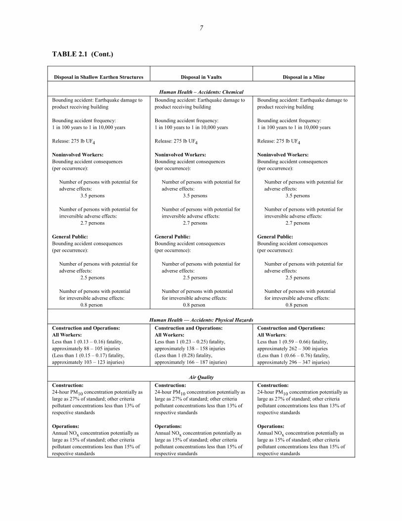
TABLE 2.1 (Cont.)
Disposal in Shallow Earthen Structures Disposal in Vaults Disposal in a Mine
Human Health – Accidents: ChemicalBounding accident: Earthquake damage toproduct receiving building
Bounding accident frequency: 1 in 100 years to 1 in 10,000 years
Release: 275 lb UF4
Noninvolved Workers: Bounding accident consequences (per occurrence):
Number of persons with potential foradverse effects:
3.5 persons
Number of persons with potential forirreversible adverse effects:
2.7 persons
General Public:Bounding accident consequences (per occurrence):
Number of persons with potential foradverse effects:
2.5 persons
Number of persons with potentialfor irreversible adverse effects:
0.8 person
Bounding accident: Earthquake damage toproduct receiving building
Bounding accident frequency: 1 in 100 years to 1 in 10,000 years
Release: 275 lb UF4
Noninvolved Workers: Bounding accident consequences (per occurrence):
Number of persons with potential foradverse effects:
3.5 persons
Number of persons with potential forirreversible adverse effects:
2.7 persons
General Public:Bounding accident consequences (per occurrence):
Number of persons with potential foradverse effects:
2.5 persons
Number of persons with potentialfor irreversible adverse effects:
0.8 person
Human Health — Accidents: Physical HazardsConstruction and Operations:All Workers: Less than 1 (0.13 – 0.16) fatality, approximately 88 – 105 injuries(Less than 1 (0.15 – 0.17) fatality, approximately 103 – 123 injuries)
Construction and Operations: All Workers:Less than 1 (0.23 – 0.25) fatality, approximately 138 – 158 injuries(Less than 1 (0.28) fatality, approximately 166 – 187 injuries)
Construction and Operations: All Workers:Less than 1 (0.59 – 0.66) fatality, approximately 262 – 300 injuries(Less than 1 (0.66 – 0.76) fatality, approximately 296 – 347 injuries)
Air QualityConstruction:24-hour PM10 concentration potentially aslarge as 27% of standard; other criteriapollutant concentrations less than 13% ofrespective standards
Operations:Annual NOx concentration potentially aslarge as 15% of standard; other criteriapollutant concentrations less than 15% ofrespective standards
Construction:24-hour PM10 concentration potentially aslarge as 27% of standard; other criteriapollutant concentrations less than 13% ofrespective standards
Operations:Annual NOx concentration potentially aslarge as 15% of standard; other criteriapollutant concentrations less than 15% ofrespective standards

8
TABLE 2.1 (Cont.)
Disposal in Shallow Earthen Structures Disposal in Vaults Disposal in a Mine
Waterb
Construction:Negligible impacts to surface water andgroundwater
Operations:None to negligible impacts to surface waterand groundwater
Construction:Negligible impacts to surface water andgroundwater
Operations:None to negligible impacts to surface waterand groundwater
Construction:Negligible impacts to surface water andgroundwater
Operations:None to negligible impacts to surface waterand groundwater
Soilb
Construction:Negligible, but temporary, impacts
Operations:No impacts
Construction:Moderate to large, but temporary, impacts
Operations:No impacts
Construction:Moderate to large, but temporary, impacts
Operations:No impacts
SocioeconomicsConstruction:Potential moderate impacts on employmentand income
Operations:Potential moderate impacts on employmentand income
Construction:Potential moderate impacts on employmentand income
Operations:Potential moderate impacts on employmentand income
Construction:Potential moderate impacts on employmentand income
Operations:Potential moderate impacts on employmentand income
EcologyConstruction:Potential moderate impacts to vegetationand wildlife
Operations:Potential adverse impacts to aquatic biota
Construction:Potential moderate impacts to vegetationand wildlife (Potential moderate to large impacts tovegetation and wildlife)
Operations:Potential adverse impacts to aquatic biota
Construction:Potential large impacts to vegetation andwildlife
Operations:Potential adverse impacts to aquatic biota
Waste ManagementNegligible to low impacts on national wastemanagement operations
Negligible to low impacts on national wastemanagement operations
Negligible to low impacts on national wastemanagement operations
Resource RequirementsNo impacts from resource requirements(such as electricity or materials) on thelocal or national scale are expected
No impacts from resource requirements(such as electricity or materials) on thelocal or national scale are expected
No impacts from resource requirements onthe local or national scale are expected;impacts of electrical requirements for mineexcavation depend on site location

9
TABLE 2.1 (Cont.)
Disposal in Shallow Earthen Structures Disposal in Vaults Disposal in a Mine
Land UseUse of approximately 46 to 55 acres;potential moderate impacts(Use of approximately 57 to 67 acres;potential moderate impacts)
Use of approximately 67 to 82 acres;potential moderate impacts(Use of approximately 82 to 97 acres;potential moderate impacts)
Use of approximately 418 to 587 acres;potential large impacts, including impactsfrom disposal of excavated material andpotential off-site traffic impacts duringconstruction(Use of approximately 547 to 770 acres;potential large impacts, including impactsfrom disposal of excavated material andpotential off-site traffic impacts duringconstruction)
a Impacts are presented for the operational period for disposal of 560,000 metric tons of UF6; impacts from the disposal of 705,000 metrictons of UF6 are shown in parentheses when different. Notation: LCF = latent cancer fatality; MEI = maximally exposed individual.
b Radiological impacts are presented as ranges resulting from disposal in 30-gal and 55-gal drums.
C Shallow Earthen Structure, Vault, or Mine. The potential impacts fromdisposal in a shallow earthen structure, vault, or mine are similar. However,disposal in a mine could create slightly larger potential impacts if the minewould have to be excavated.
CCCC Transportation. Disposal of UF4 would require the shipment of the depletedUF4 from a conversion plant to the disposal facility. The UF4 would bepackaged in 30-gal or 55-gal drums and shipped by either truck or train, inaccordance with DOE and U.S. Department of Transportation (DOT)regulatory requirements. The greatest risk from UF4 shipments would be fromtypical traffic accidents, unrelated to the radiological or chemical nature of theUF4. Although less than 1 traffic fatality would be expected to result fromshipment of the entire inventory, these vehicle-related risks would be about5 times larger than the radiological and chemical risks combined.
The potential impacts estimated for the post-closure phase are subject to a great deal ofuncertainty because of the extremely long time period considered and the dependence of predictionson the behavior of the waste material as it interacts with soil and water in a distant futureenvironment. The post-closure impacts would depend greatly on the specific disposal facility designand site-specific characteristics. Because of these uncertainties, the assessment assumptions weregenerally selected to produce conservative estimates of impact, that is, they tend to overestimate theexpected impact. Changes in key disposal assumptions could yield significantly different results (seeSection 7).
10
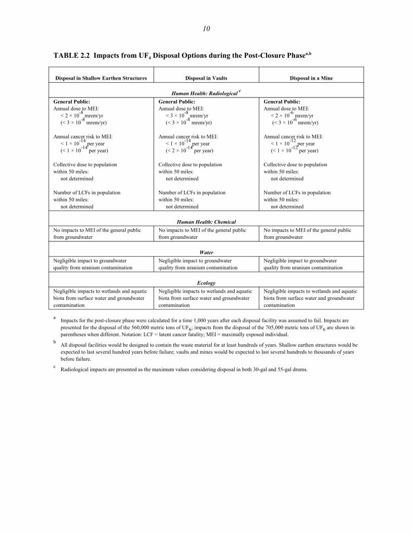
TABLE 2.2 Impacts from UF4 Disposal Options during the Post-Closure Phasea,b
Disposal in Shallow Earthen Structures Disposal in Vaults Disposal in a Mine
Human Health: Radiological c
General Public:Annual dose to MEI:
< 2 × 10⁻⁸ mrem/yr (< 3 × 10⁻⁸ mrem/yr)
Annual cancer risk to MEI: < 1 × 10-14 per year(< 1 × 10-14 per year)
Collective dose to population within 50 miles:
not determined
Number of LCFs in population within 50 miles:
not determined
General Public:Annual dose to MEI:
< 3 × 10⁻⁸ mrem/yr (< 3 × 10⁻⁸ mrem/yr)
Annual cancer risk to MEI: < 1 × 10-14 per year(< 2 × 10-14 per year)
Collective dose to population within 50 miles:
not determined
Number of LCFs in population within 50 miles:
not determined
General Public:Annual dose to MEI:
< 2 × 10⁻⁶ mrem/yr (< 3 × 10⁻⁶ mrem/yr)
Annual cancer risk to MEI: < 1 × 10-12 per year(< 1 × 10-12 per year)
Collective dose to population within 50 miles:
not determined
Number of LCFs in population within 50 miles:
not determined
Human Health: ChemicalNo impacts to MEI of the general publicfrom groundwater
No impacts to MEI of the general publicfrom groundwater
No impacts to MEI of the general publicfrom groundwater
WaterNegligible impact to groundwaterquality from uranium contamination
Negligible impact to groundwaterquality from uranium contamination
Negligible impact to groundwaterquality from uranium contamination
EcologyNegligible impacts to wetlands and aquaticbiota from surface water and groundwatercontamination
Negligible impacts to wetlands and aquaticbiota from surface water and groundwatercontamination
Negligible impacts to wetlands and aquaticbiota from surface water and groundwatercontamination
a Impacts for the post-closure phase were calculated for a time 1,000 years after each disposal facility was assumed to fail. Impacts arepresented for the disposal of the 560,000 metric tons of UF6; impacts from the disposal of the 705,000 metric tons of UF6 are shown inparentheses when different. Notation: LCF = latent cancer fatality; MEI = maximally exposed individual.
b All disposal facilities would be designed to contain the waste material for at least hundreds of years. Shallow earthen structures would beexpected to last several hundred years before failure; vaults and mines would be expected to last several hundreds to thousands of yearsbefore failure.
c Radiological impacts are presented as the maximum values considering disposal in both 30-gal and 55-gal drums.

11
The following general summary of potential environmental impacts during the post-closurephase is taken from information in Table 2.2 and Section 7 (post-closure impacts):
C Potential Adverse Impacts. For all disposal options, essentially no impactswould occur for a disposal facility in a dry environmental setting within1,000 years after the facility was assumed to fail. Although UF4 was assumedto be released to the environment, the relatively low solubilities of UF4 and theuranium compounds formed by reaction of UF4 with infiltrating water, and thelow water infiltration rate typical of dry environmental settings, would resultin only a very small amount of uranium reaching the groundwater table within1,000 years. The maximum dose to an individual assumed to live at the edgeof the disposal site and use the contaminated water was estimated to beextremely small, approximately 1 × 10⁻⁶ mrem/yr. Possible exposures (on theorder of 10 rem/yr) could occur for shallow earthen structures and vaults if thecover material were to erode and expose the uranium material; however, thissituation would not occur until several thousand years after emplacement orfailure, and the exposure could be eliminated by adding new cover materialto the top of the waste area.
C Shallow Earthen Structure, Vault, or Mine. Because of the long time periodsconsidered and the fact that the calculations were performed for a time of1,000 years after each facility was assumed to fail, the potential impacts fromdisposal in a shallow earthen structure, vault, or mine would be very similar.However, shallow earthen structures would be expected to contain the wastematerial for a period of at least several hundred years before failure, whereasvaults or a mine would be expected to last even longer — from severalhundred years to a thousand years or more. Therefore, vault and mine disposalwould provide longer protection of waste. In addition, a vault and a minewould be expected to provide additional protection against erosion of thecover material (and possible surface exposure of the waste material) whencompared with shallow earthen structures. The exact time that any disposalfacility would perform as designed would depend on the specific facilitydesign and site characteristics and is beyond the scope of this assessment.
12
3 DEPLETED UF4 BACKGROUND INFORMATION
3.1 PHYSICAL CHARACTERISTICS OF UF4
Uranium tetrafluoride (UF4) is often called green-salt because of its characteristic color.Depleted UF4 is a solid composed of agglomerating particles. Its texture is similar to that of bakingsoda. It is nonvolatile and nonhydroscopic but only slightly soluble in water: about 40 parts permillion (ppm) at room temperature (Katz et al. 1986). It has a particle density of 6.5 g/cm3; however,its bulk density depends on the production process and the properties of the starting uraniumcompounds, ranging between 2.0 and 4.5 g/cm3. It is generally an intermediate in the conversion ofUF6 to either uranium oxide or uranium metal. The physical properties of depleted UF4 aresummarized in Table 3.1.
After exposure to water, UF4 slowly dissolves and undergoes hydrolysis, forming severalpossible uranium compounds and HF. The time for hydrolysis can be significant. Tomasko (2001)presents a discussion of the chemical reactions possible when UF4 reacts with water in a disposalenvironment. Possible reaction products include U3O8, schoepite (UO3@2H2O), and several uraniumcomplexes. The final form of uranium in solution in the groundwater below a disposal facility is acomplex function of the reaction time, physical and chemical attributes of the disposal facility, andgeochemistry of the receiving water (Tomasko 2001).
3.2 SUITABILITY OF UF4 FOR DISPOSAL
One potential concern with the disposal of depleted UF4 has been the fact that it reactsslowly with moisture at ambient temperature and releases HF, which potentially could enhance thecorrosion rate of disposal packages or the disposal facility itself. In addition, UF4 has a highersolubility in water than the uranium oxides U3O8 and UO2. These were two of the reasons that theconversion to UF4 and disposal of UF4 were considered in the PEIS but not analyzed in detail.Specifically, the disposal of UF4 was not considered in detail in the PEIS for the following reasons:
C A 1994 DOE Request for Recommendations (59 FR 56324) solicitedsuggestions for potential uses of depleted UF6 and for any technologies thatcould facilitate the long-term management of depleted UF6. No responsessuggested conversion to UF4 or disposal as UF4.

13
TABLE 3.1 Physical Properties of UF4
Melting Point(EC)
Bulk Density(g/cm3)
Solubility in WaterNeutral pH
Inhalation SolubilityClassa
960±5 2.0–4.5 Very slightly soluble W
a D, W, and Y are inhalation solubility classes established by the International Commission onRadiation Protection. Class D material is very soluble; lung retention time is days. Class W materialis relatively insoluble; lung retention time is weeks. Class Y material is relatively insoluble; lungretention time is years.
Source: Martin Marietta Energy Systems (MMES 1990).
C DOE and its contractors felt that there was no particular environmentaladvantage to UF4 over oxides. On the contrary, there was some concern thatUF4 may not meet the waste acceptance criteria for low-level waste (LLW)disposal sites because of HF generation when UF4 reacts with water andbecause UF4 has a higher solubility than oxides.
C For practical reasons, there was a desire to limit the number of optionsanalyzed in detail in the PEIS to a reasonable number.
C DOE held three scoping meetings in February 1996, soon after the Notice ofIntent to prepare the PEIS was issued. There was also a 60-day commentperiod. Only one individual at one meeting suggested conversion to UF4 ordisposal as UF4. Similarly, when the draft PEIS was issued, there was alengthy public review period (120 days). Approximately 600 comments werereceived; no comments mentioned conversion to UF4 or disposal as UF4.
Recent information, summarized below, supports future consideration of UF4 as a suitabledisposal form.
C Folga and Kier (2001). This engineering analysis report for UF4 disposalreports that a much smaller amount of UF4 than was considered here(approximately 1,870 metric tons) was disposed of in a shallow land LLWdisposal facility at the Nevada Test Site (NTS) in the past. Disposal wasaccomplished by using standard disposal boxes, without any additionaloverpacking or treatment of the bulk depleted UF4. A review of the propertiesof depleted UF4 in bulk form by personnel from NTS and the Fernald Sitebefore its shipment to NTS did not reveal any major issues associated with thereactivity of UF4.

14
C Croff et al. (2000). This study by Oak Ridge National Laboratory evaluatedthe acceptability of several depleted uranium conversion products at potentialLLW disposal sites to provide a basis for DOE decisions on the preferreddepleted uranium product form. The study concluded that depleted UF4 shouldbe acceptable for near-surface disposal at sites such as NTS and Envirocare.Although some characteristics (e.g., very fine particles, sorbed HF) could limitthe acceptability of depleted UF4 for disposal, these characteristics reportedlycan be controlled via proper technical specifications imposed on the productforms.
C Tomasko (2001). This report evaluated potential groundwater concentrationsfollowing failure of a UF4 disposal facility in a representative dry environmentfor a range of site characteristics. The results of the evaluation, discussed inmore detail in Section 7, indicate that uranium groundwater concentrationswould remain well below levels of concern for thousands of years, even underconservative site assumptions.
15
4 ASSESSMENT ASSUMPTIONS AND METHODOLOGY
The areas of potential environmental impact discussed in this report are the same as thosediscussed in the PEIS (Figure 4.1). For each technical area, analytical methods similar or identicalto those used for the PEIS were used to estimate the potential impacts from construction, operations,and accidents for each of the UF4 disposal options. A complete discussion of the methods used foreach technical area is provided in Chapter 4 and Appendix C of the PEIS. Changes to methods orassumptions are noted in Chapters 6 and 7, where appropriate.
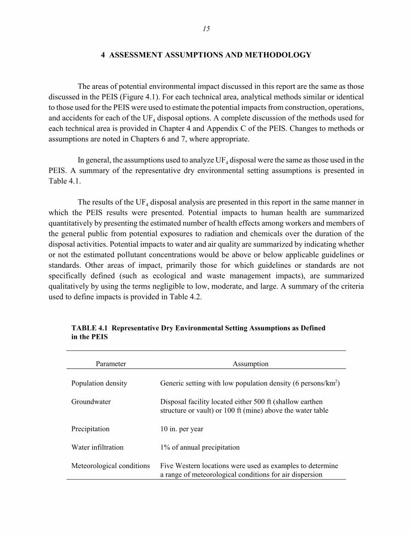
In general, the assumptions used to analyze UF4 disposal were the same as those used in thePEIS. A summary of the representative dry environmental setting assumptions is presented inTable 4.1.
The results of the UF4 disposal analysis are presented in this report in the same manner inwhich the PEIS results were presented. Potential impacts to human health are summarizedquantitatively by presenting the estimated number of health effects among workers and members ofthe general public from potential exposures to radiation and chemicals over the duration of thedisposal activities. Potential impacts to water and air quality are summarized by indicating whetheror not the estimated pollutant concentrations would be above or below applicable guidelines orstandards. Other areas of impact, primarily those for which guidelines or standards are notspecifically defined (such as ecological and waste management impacts), are summarizedqualitatively by using the terms negligible to low, moderate, and large. A summary of the criteriaused to define impacts is provided in Table 4.2.
TABLE 4.1 Representative Dry Environmental Setting Assumptions as Defined in the PEIS
Parameter Assumption
Population density Generic setting with low population density (6 persons/km2)
Groundwater Disposal facility located either 500 ft (shallow earthenstructure or vault) or 100 ft (mine) above the water table
Precipitation 10 in. per year
Water infiltration 1% of annual precipitation
Meteorological conditions Five Western locations were used as examples to determinea range of meteorological conditions for air dispersion

16
FIGURE 4.1 Areas of Potential Impact Evaluated in the Depleted UF4 Disposal Analysis

17
TABLE 4.2 General Criteria Used to Summarize and Describe the Magnitude of Environmental Impacts
General Criteria Used to Define Descriptor Term
Area of Impact Negligible to Low Moderate Large
Human health and safety(construction, operations,transportation)
Human health and safety impacts are provided in terms of the number or degree of healtheffects (impacts are not described in terms of negligible to low, moderate, or large)
Air quality Air quality impacts are compared with applicable air standards or guidelines (impacts are notdescribed in terms of negligible to low, moderate, or large)
Surface waterRunoff No observable increase in
runoff.Increased runoff, butmanageable through existingdrainage patterns
Existing drainage patternspossibly inadequate tohandle increased runoff.
Floodplains No observable change inexisting floodplains
Change in existingfloodplain area of between1% and 10%
Change in existingfloodplain area of more than10%
Water quality Water quality impacts are compared with applicable water quality standards or guidelines(impacts are not described in terms of negligible to low, moderate, or large)
GroundwaterRecharge No observable change in
rechargeObservable change involumetric flow of waterreaching the groundwateraquifer, but less than a 50%change in the existing rate
Change in volumetric flow ofwater reaching thegroundwater aquifer of morethan 50%
Depth to groundwater No observable change Change of less than 10%from the current value
Change of more than 10%from the current value
Water quality Water quality impacts are compared with water quality standards or guidelines (impacts are notdescribed in terms of negligible to low, moderate, or large)
SoilTopography No observable change in
elevationsChanges in elevation of lessthan 5 ft over the areaimpacted
Changes in elevation of morethan 5 ft over the areaimpacted
Permeability No observable change ininfiltration
Changes of less than 50% ininfiltration
Changes of more than 50%in infiltration
Erosion potential No observable change in soilloss
Changes in soil loss of lessthan 50% of existing rate
Changes in soil loss of morethan 50% of the existing rate
Soil quality Soil quality impacts are compared with EPA guidelines (impacts are not described in terms ofnegligible to low, moderate, or large)

18
TABLE 4.2 (Cont.)
General Criteria Used to Define Descriptor Term
Area of Impact Negligible to Low Moderate Large
SocioeconomicsEconomic activity Less than 0.1 percentage
point increase in annualemployment growth rate inthe region of influence
Between 0.1 and 1.0percentage point increase inannual employment growthrate in the region ofinfluence
More than 1.0 percentagepoint increase in annualemployment growth rate inthe region of influence
Population Less than 0.1 percentagepoint increase in annualpopulation growth rate inthe region of influence
Between 0.1 and 1.0percentage point increase inannual population growthrate in the region ofinfluence
More than 1.0 percentagepoint increase in annualpopulation growth rate in theregion of influence
Housing Less than 20% of vacanthousing units required in theregion of influence
Between 20% and 50% ofvacant housing unitsrequired in the region ofinfluence
More than 50% of vacanthousing units required in theregion of influence
Public finance Less than 1% increase inlocal jurisdictional revenuesand expenditures
Between 1% and 5%increase in localjurisdictional revenues andexpenditures
More than 5% increase inlocal jurisdictional revenuesand expenditures
Ecology No mortality of individualorganisms; no measurableeffects on population orcommunity parameters;general guideline of lessthan 10 acres of habitat loss.
Mortality of a small numberof individual organisms;short-term effects onpopulation or communityparameters; generalguideline of between 10 and100 acres of habitat loss
Mortality of a large numberof individual organisms;long-term effects onpopulation or communityparameters; general guidelineof more than 100 acres ofhabitat loss
Waste management Little or no change in wastefacility operations orcapacity requirements (i.e.,less than 10% increasedwaste loading ortreatment/disposal capacityrequirements)
Likely increase in capacityneeded at existing facilities(i.e., increase of 10% to 100% in waste loading ortreatment/disposal capacityrequirements)
Change in waste facility(s)operations and need forincreased capacity(i.e., increase of more than100% in waste loading ortreatment/disposal capacityrequirements)
Resource requirements Required quantities ofcommonly used materials forconstruction and operationof facilities less than 5% ofexisting local capacity; nouse of uncommon materialssuch as Monel and Inconel
Required quantities ofcommonly used materials forconstruction and operationof facilities more than 5% ofexisting local capacity; useof small amounts ofuncommon materials such asMonel and Inconel
Required quantities ofcommonly used materials forconstruction and operation offacilities more than 90% ofexisting local capacity; useof large amounts ofuncommon materials such asMonel and Inconel

19
TABLE 4.2 (Cont.)
General Criteria Used to Define Descriptor Term
Area of Impact Negligible to Low Moderate Large
Land use No effect on land-usepatterns and traffic flow;general guideline of land-userequirement of less than50 acres
Land-use patterns affected;land conversion likely;traffic congestion atintersections during peakhours, with change in level-of-service rating; generalguideline of land-userequirement of between 50and 200 acres
Land-use patterns affected;land conversion in conflictwith existing land-use plansand controls; traffic flowrestricted, with congestion atintersections, with a highlevel-of-service rating;general guideline of land-userequirement of more than200 acres
Cultural resources Cultural resource criteria are not defined because potential impacts could not be ranked (eitherthey would occur or would not occur) and were considered only in a site-specific context
Environmental justice Environmental justice criteria are not defined because potential impacts could not be ranked(either they would occur or would not occur) and were considered only in a site-specificcontext

20
5 DESCRIPTION OF DISPOSAL FACILITY OPTIONS
This section provides a brief summary of the different disposal facility options consideredin the assessment of depleted UF4 disposal impacts. The information is based on preconceptualdesign data provided in the UF4 engineering analysis report (Folga and Kier 2001). The engineeringanalysis report includes much more detailed information, such as descriptions of facility layouts andresource requirements; estimates of effluents, wastes, and emissions; and descriptions of potentialaccident scenarios.
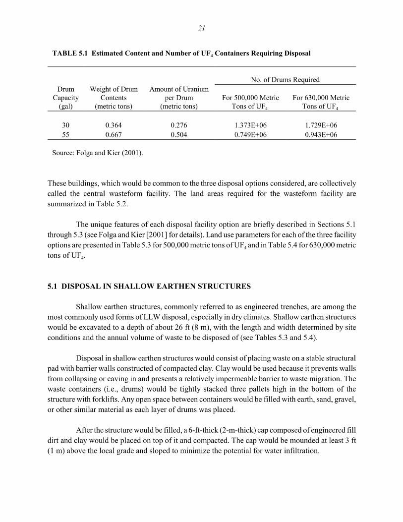
The three disposal facility options considered are shallow earthen structures (engineeredtrenches), vaults, and an underground mine. The depleted UF4 would be produced and packaged ata chemical conversion facility and shipped via truck or rail to the disposal site. For each option, itwas assumed that the UF4 would be packaged in either 30-gal (110-L) or 55-gal (208-L) drums. Twodrum sizes were considered for two reasons: (1) to account for uncertainties in the actual packagesthat would be used if UF4 were produced for disposal and (2) in recognition of the fact that therelatively large weight of a 55-gal drum loaded with UF4 could pose handling problems at a disposalsite. The properties and numbers of drums requiring disposal for the two depleted UF6 inventoriesconsidered are summarized in Table 5.1.
A disposal facility for depleted UF4 would consist of a disposal area and two major typesof buildings:
1. Warehouse for receiving and shipping products — in which containersshipped to the disposal facility would be temporarily stored and then inspectedand transported to a disposal unit. If the inspection were to show that a drumwas defective, its contents would be repackaged (i.e., transferred to anotherdrum) before being transferred to a disposal unit from the shipping part of thebuilding. The damaged drums could be crushed and disposed of as LLW, orthey could be decontaminated and recycled as scrap metal, if allowed byfederal and state regulations at the time.
2. Administration building — that would incorporate all technical andadministrative support functions needed to manage the operation of thedisposal facility. These functions include security, facility access control,health physics and radiation badges, sanitary facilities, work control andpersonnel support, internal and external (public relations) communications,spill or emergency response provisions, analytical laboratory, environmentalregulatory reporting, and records management for materials control andaccountability (MC&A).
21
TABLE 5.1 Estimated Content and Number of UF4 Containers Requiring Disposal
DrumCapacity
(gal)
Weight of DrumContents
(metric tons)
Amount of Uraniumper Drum
(metric tons)
No. of Drums Required
For 500,000 MetricTons of UF4
For 630,000 MetricTons of UF4
30 0.364 0.276 1.373E+06 1.729E+0655 0.667 0.504 0.749E+06 0.943E+06
Source: Folga and Kier (2001).
These buildings, which would be common to the three disposal options considered, are collectivelycalled the central wasteform facility. The land areas required for the wasteform facility aresummarized in Table 5.2.
The unique features of each disposal facility option are briefly described in Sections 5.1through 5.3 (see Folga and Kier [2001] for details). Land use parameters for each of the three facilityoptions are presented in Table 5.3 for 500,000 metric tons of UF4 and in Table 5.4 for 630,000 metrictons of UF4.
5.1 DISPOSAL IN SHALLOW EARTHEN STRUCTURES
Shallow earthen structures, commonly referred to as engineered trenches, are among themost commonly used forms of LLW disposal, especially in dry climates. Shallow earthen structureswould be excavated to a depth of about 26 ft (8 m), with the length and width determined by siteconditions and the annual volume of waste to be disposed of (see Tables 5.3 and 5.4).
Disposal in shallow earthen structures would consist of placing waste on a stable structuralpad with barrier walls constructed of compacted clay. Clay would be used because it prevents wallsfrom collapsing or caving in and presents a relatively impermeable barrier to waste migration. Thewaste containers (i.e., drums) would be tightly stacked three pallets high in the bottom of thestructure with forklifts. Any open space between containers would be filled with earth, sand, gravel,or other similar material as each layer of drums was placed.
After the structure would be filled, a 6-ft-thick (2-m-thick) cap composed of engineered filldirt and clay would be placed on top of it and compacted. The cap would be mounded at least 3 ft(1 m) above the local grade and sloped to minimize the potential for water infiltration.

22
TABLE 5.2 Site Land Parameters at the Wasteform Facility
500,000 Metric Tons of UF4 630,000 Metric Tons of UF4
Parameter 30-gal Drums 55-gal Drums 30-gal Drums 55-gal Drums
Site land area (ha) 1.7 1.4 1.7 1.4Disturbed land area (ha) 1.7 1.4 1.7 1.4Total fenced area (ha) 1.6 1.3 1.6 1.3Total paved area (ha) 0.33 0.28 0.34 0.28Total excavated material (m3) 9,550 7,550 9,750 7,550
TABLE 5.3 Site Land Parameters for Disposal of 500,000 Metric Tons of UF4
ParameterShallow Earthen
Structure Vaults Mine
Disposal in 30-gal drumsSite land area (ha) 20.6 25.4 236Disturbed land area (ha) 18.7 25.4 236Total fenced area (ha) 20.6 25.4 236Total paved area (ha) 0.9 3.5 12Total excavated material (m3) 1.29E+06 5.71E+05 1.22E+06Facility length (m) 597 552 1,586Facility width (m) 344 460 1,560Underground site land area (ha) NAa NA 247
Disposal in 55-gal drumsSite land area (ha) 17.4 31.6 168Disturbed land area (ha) 15.7 31.6 168Total fenced area (ha) 17.4 31.6 168Total paved area (ha) 0.8 4.4 11Total excavated material (m3) 1.06E+06 6.31E+05 9.91E+05Facility length (m) 506 688 1,355Facility width (m) 344 460 1,378Underground site land area (ha) NA NA 187
a NA = not applicable.
Source: Folga and Kier (2001).

23
TABLE 5.4 Site Land Parameters for Disposal of 630,000 Metric Tons of UF4
ParameterShallow Earthen
Structure Vaults Mine
Disposal in 30-gal drumsSite land area (ha) 25.5 31.6 310Disturbed land area (ha) 23.4 31.6 310Total fenced area (ha) 25.5 31.6 310Total paved area (ha) 1.0 4.4 12Total excavated material (m3) 1.65E+06 7.14E+05 1.44E+06Facility length (m) 597 688 1,740Facility width (m) 427 460 1,782Underground site land area (ha) NAa NA 310
Disposal in 55-gal drumsSite land area (ha) 21.6 37.9 220Disturbed land area (ha) 19.7 37.9 220Total fenced area (ha) 21.6 37.9 220Total paved area (ha) 0.9 5.2 12Total excavated material (m3) 1.36E+06 7.89E+05 1.16E+06Facility length (m) 506 824 1,509Facility width (m) 427 460 1,548Underground site land area (ha) NA NA 234
a NA = not applicable.
Source: Folga and Kier (2001).
5.2 DISPOSAL IN VAULTS
Belowground vaults are subsurface reinforced concrete structures. For the preconceptualdesign basis, the vaults were assumed to be 131 ft (40 m) wide × 266 ft (81 m) long, with a heightof approximately 20 ft (6 m). The concrete walls were assumed to be 1 ft (0.3 m) thick, with a floorslab thickness of 2 ft (0.6 m). The majority of the structure would be located underground, with onlythe roof area above grade.
Each vault was assumed to be divided into five sections, each section approximately 66 ft(20 m) long by 26 ft (8 m) wide and 13 ft (4 m) tall. As opposed to shallow earthen structures, thewalls and floor of a vault would be constructed of reinforced concrete. A crane would be used to
24
place drums within each section. Once a vault would be full, any open space between containerswould be filled with earth, sand, gravel, or other similar material. A permanent roof slab ofreinforced concrete that would completely cover the vault would be installed after all five sectionswere filled. A cap of engineered fill dirt and clay would be placed on top of the concrete cover andcompacted. The cap would be mounded above the local grade and sloped to minimize the potentialfor water infiltration.
5.3 DISPOSAL IN A MINE
An underground mine disposal facility would be a repository for permanent deep geologicaldisposal. A mine disposal facility could either use a previously existing mine or be constructed forthe sole purpose of waste disposal. For purposes of comparing options, the conservative assumptionof constructing a new mine was assessed for this analysis. A mine disposal facility would consist ofsurface facilities that would provide space for waste receiving and inspection (the wasteform facility)and of shafts and ramps that would provide access to and ventilation of the underground portion ofthe repository.
The underground portion would consist of tunnels (called “drifts”) for the transport anddisposal of waste underground. The dimensions of the drifts were assumed to be 21 ft (6.5 m) wide× 330 ft (100 m) long and 18 ft (5 m) high. Waste containers would be placed in drifts, and the driftswould be backfilled with loose material after emplacement.

25
6 IMPACTS OF OPTIONS — OPERATIONAL PHASE
Potential impacts analyzed for the operational phase of the depleted UF4 disposal facilityoptions included impacts occurring during facility construction and during the period when the wastematerial would be actively placed into disposal units (20 years for disposal of 500,000 metric tonsof UF4; 25 years for disposal of 630,000 metric tons of UF4). The potential environmental impactsduring the post-closure period, after the disposal facility would cease operations, are presented inSection 7; transportation impacts are presented in Section 8. The estimated operational impacts arediscussed in this section for each area of impact.
The environmental impacts during the operational phase were evaluated on the basis of theinformation described in the UF4 engineering analysis report (Folga and Kier 2001). The followinggeneral assumptions apply to the assessment of impacts:
C Impacts during the operational phase include those from preliminary facilityconstruction and the period when UF4 would be actively placed into disposalunits. Construction of disposal units would occur incrementally while wastematerial was being received.
C Bulk (ungrouted) UF4 would be disposed of directly without significantprocessing at the disposal facility. Consequently, essentially no UF4 air orwater emissions would be associated with normal (nonaccident) operations.Emissions would include dust during construction and exhaust emissions fromequipment used during construction and waste emplacement.
C The potential impacts from disposal were analyzed for a generic dryenvironmental setting. The historical meteorological conditions for five actualdry locations in the southwestern United States were used for dispersioncalculations. It was assumed that a disposal facility would be located in a ruralarea with a population density of 15 persons/mi2 (6 persons/km2).
6.1 HUMAN HEALTH — NORMAL OPERATIONS
6.1.1 Radiological Impacts
Radiological impacts during normal operations of the facility were estimated for involvedworkers, noninvolved workers, and members of the general public. External radiation resulting fromthe handling and shipping of uranium materials would be the major source of exposure for involved

26
workers. Variations in exposures for the three disposal types considered (shallow earthen structures,vaults, or mine) would be caused by different practices employed for emplacement in the threedifferent types of disposal facilities. Disposal in a mine would require transport of waste containersfrom the ground surface to the underground cavities, whereas disposal in shallow earthen structuresand vaults would require filling and capping efforts to cover the waste containers with dirt, cement,and/or other engineering materials. Variations in the results for 30-gal drums and 55-gal drumswould be caused by different dose rates due to different sizes of containers and different numbersof containers to be handled. In general, the average radiation exposure to involved workers wouldbe less than 650 mrem/yr.
Exposures to noninvolved workers and the general public could result if there were releasesof uranium compounds to the atmosphere or surface water. However, during normal operations, noreleases would be expected (Folga and Kier 2001); therefore, potential exposures would be zero forthese two groups of receptors.
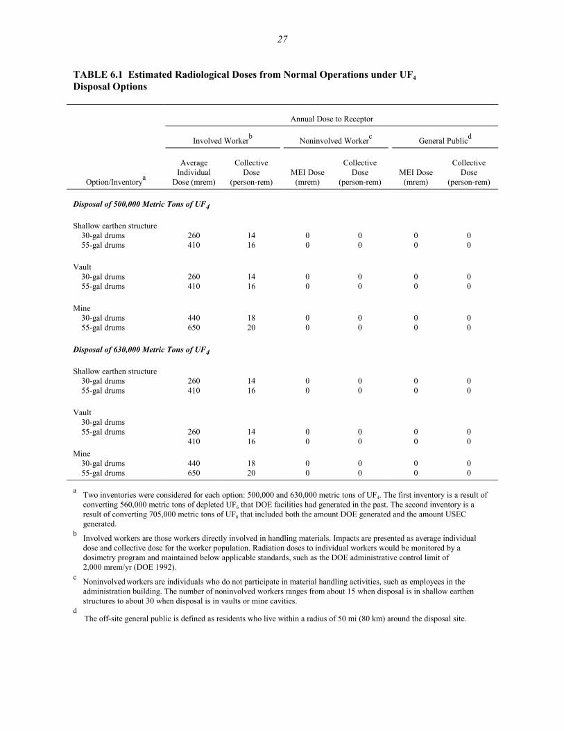
The estimated potential radiation exposures for the different disposal options are listed inTable 6.1. The risk of latent cancer fatalities (LCFs) resulting from the exposures presented inTable 6.1 are presented in Table 6.2. The risks presented in Table 6.2 were estimated by multiplyingthe radiation doses by health risk conversion factors of 4 × 10⁻⁴ LCF/person-rem for workers and5 × 10-4 LCF/person-rem for members of the public. Detailed discussions of the methodology usedin the radiological impact analyses are provided in Appendix C of the PEIS (DOE 1999) and Chenget al. (1997).
6.1.1.1 Disposal of 500,000 Metric Tons of UF4
The estimated radiation exposures to involved workers from disposal of UF4 in 55-galdrums would be somewhat greater than the radiation exposures from disposal of UF4 in 30-galdrums. Annual collective doses would range from 14 to 18 person-rem/yr for disposal in 30-galdrums and from 16 to 20 person-rem/yr in 55-gal drums. These collective doses would result in lessthan 1 × 10⁻² fatalities per year (1 additional latent cancer fatality [LCF] in 100 years).
Estimated average worker doses for disposal in 30 gal-drums would range from 260 to440 mrem/yr. For disposal in 55-gal drums, the average doses would range from 410 mrem/yr to650 mrem/yr. Potential exposures of involved workers would be well below the radiation dose limitof 5,000 mrem/yr (Code of Federal Regulations, Title 10, Part 835 [10 CFR Part 835]).
In general, greater radiation exposures would be expected from disposal in a mine than fromdisposal in shallow earthen structures or vaults. For the latter two disposal technologies, radiationexposures would be about the same.
27
TABLE 6.1 Estimated Radiological Doses from Normal Operations under UF4 Disposal Options
Annual Dose to Receptor
Involved Workerb Noninvolved Workerc General Publicd
Option/Inventorya
AverageIndividual
Dose (mrem)
CollectiveDose
(person-rem)MEI Dose
(mrem)
CollectiveDose
(person-rem)MEI Dose
(mrem)
CollectiveDose
(person-rem)
Disposal of 500,000 Metric Tons of UF4
Shallow earthen structure30-gal drums55-gal drums
260410
1416
00
00
00
00
Vault30-gal drums55-gal drums
260410
1416
00
00
00
00
Mine30-gal drums55-gal drums
440650
1820
00
00
00
00
Disposal of 630,000 Metric Tons of UF4
Shallow earthen structure30-gal drums55-gal drums
260410
1416
00
00
00
00
Vault30-gal drums55-gal drums 260
4101416
00
00
00
00
Mine30-gal drums55-gal drums
440650
1820
00
00
00
00
a Two inventories were considered for each option: 500,000 and 630,000 metric tons of UF4. The first inventory is a result ofconverting 560,000 metric tons of depleted UF6 that DOE facilities had generated in the past. The second inventory is aresult of converting 705,000 metric tons of UF6 that included both the amount DOE generated and the amount USECgenerated.
b Involved workers are those workers directly involved in handling materials. Impacts are presented as average individualdose and collective dose for the worker population. Radiation doses to individual workers would be monitored by adosimetry program and maintained below applicable standards, such as the DOE administrative control limit of2,000 mrem/yr (DOE 1992).
c Noninvolved workers are individuals who do not participate in material handling activities, such as employees in theadministration building. The number of noninvolved workers ranges from about 15 when disposal is in shallow earthenstructures to about 30 when disposal is in vaults or mine cavities.
d The off-site general public is defined as residents who live within a radius of 50 mi (80 km) around the disposal site.

28
TABLE 6.2 Estimated Latent Cancer Fatality Risks from Normal Operations under UF4 Disposal Options
Annual Risk to Receptor
Involved Workerb Noninvolved Workerc General Publicd
Option/Inventorya
AverageRisk (risk)
CollectiveRisk
(fatalities)MEI Risk
(risk)
CollectiveRisk
(fatalities)MEI Risk
(risk)
CollectiveRisk
(fatalities)
Disposal of 500,000 Metric Tons of UF4
Shallow earthen structure30-gal drums55-gal drums
1 × 10⁻⁴
2 × 10⁻⁴ 6 × 10⁻³
6 × 10⁻³ 00
00
00
00
Vault30-gal drums55-gal drums
1 × 10⁻⁴
2 × 10⁻⁴ 6 × 10⁻³
6 × 10-300
00
00
Mine30-gal drums55-gal drums
2 × 10⁻⁴
3 × 10⁻⁴ 7 × 10⁻³
8 × 10⁻³ 00
00
00
00
Disposal of 630,000 Metric Tons of UF4
Shallow earthen structure30-gal drums55-gal drums
1 × 10⁻⁴
2 × 10⁻⁴ 6 × 10⁻³
6 × 10⁻³ 00
00
00
00
Vault30-gal drums55-gal drums
1 × 10⁻⁴
2 × 10⁻⁴ 6 × 10⁻³
6 × 10⁻³ 00
00
00
00
Mine30-gal drums55-gal drums
2 × 10⁻⁴
3 × 10⁻⁴ 7 × 10⁻³
8 × 10⁻³ 00
00
00
00
a Two inventories were considered for each option: 500,000 and 630,000 metric tons of UF4. The first inventory is a resultof converting 560,000 metric tons of UF6 that DOE facilities had generated in the past. The second inventory is a result ofconverting 705,000 metric tons of UF6 that included both the amount DOE generated and the amount USEC generated.
b Involved workers are those workers directly involved in handling materials. Impacts are presented as average individualrisk and collective risk for the worker population.
c Noninvolved workers are individuals who do not participate in material handling activities, such as employees in theadministration building. The number of noninvolved workers ranges from about 15 when disposal is in shallow earthenstructures to about 30 when disposal is in vaults or mine cavities.
d The off-site general public is defined as residents who live within a radius of 50 mi (80 km) around the disposal site.

29
6.1.1.2 Disposal of 630,000 Metric Tons of UF4
Although the inventory of depleted UF4 would increase from 500,000 to 630,000 metrictons, the annual radiation exposures for the receptors considered would be the same as that reportedin Section 6.1.1.1. This is because the amount of UF4 that would be handled per year is assumed tobe the same for both cases. However, cumulative exposures from the entire operational period wouldbe greater for disposal of 630,000 metric tons than for disposal of 500,000 metric tons because theoperational period would increase from 20 to 25 years.
6.1.2 Chemical Impacts
Chemical impacts to the general public, noninvolved workers, and involved workers duringthe operational phase of the depleted UF4 disposal facility were considered. The only reasonablewaste form option considered for depleted UF4 disposal was the ungrouted form, which would bepackaged at the conversion facility. Therefore, no chemical impacts to the general public ornoninvolved workers would occur at the disposal facility, because airborne emissions would not beexpected (Folga and Kier 2001).
For involved workers, the only potential exposures would occur from repackaging the smallnumber of drums that would require it as a result of handling damage. The engineering analysisreport (Folga and Kier 2001) states that approximately 25 drums would require repackagingannually, whether disposal was in 30-gal or 55-gal drums. For drum repackaging, electricallypowered transfer equipment would pour the contents of the damaged drums into new drums,minimizing worker contact with the drum contents. The transfer equipment would operate in sucha way as to keep the operation enclosed and eliminate UF4 dust generation. Therefore, exposure ofinvolved workers to UF4 dust would be very low and well below occupational exposure standards.
6.2 HUMAN HEALTH — ACCIDENT CONDITIONS
A range of accidents covering the spectrum of high-frequency/low-consequence accidentsto low-frequency/high-consequence accidents was considered in the UF4 engineering analysis report(Folga and Kier 2001). These accidents are listed in Table 6.3. The following sections present theresults for radiological and chemical health impacts of the highest consequence accident in eachfrequency category considered. Detailed descriptions of the methodology and assumptions used inthese calculations are provided in Appendix C of the PEIS and Policastro et al. (1997).

30
TABLE 6.3 Accidents Considered under UF4 Disposal Optionsa
Option/AccidentScenario Accident Description
ChemicalForm
AmountReleased
(lb)Duration
(min)ReleaseLevel
Likely Accidents (frequency: 1 or more times in 100 years)
Mishandling/drop ofdrum inside the productreceiving area
A single UF4 drum is damaged by a forklift andspills its contents onto the ground inside theproduct receiving area.
UF4 0.000079(0.00015)
Puff Stack
Mishandling/drop ofdrum outside the productreceiving area
A single UF4 drum is damaged by a forklift andspills its contents outside the product receivingarea.
UF4 0.079(0.15)
Puff Ground
Unlikely Accidents (frequency: 1 in 100 years to 1 in 10,000 years)
Earthquake The product receiving area is damaged during adesign-basis earthquake, resulting in failure ofthe structure and confinement systems.
UF4 275(275)
Puff Ground
Tornado A major tornado and associated tornado missilesresult in failure of the product receiving areastructures and confinement systems.
UF4 275(275)
Puff Ground
Extremely Unlikely Accidents (frequency: 1 in 10,000 years to 1 in 1 million years)
Fire/explosion inside theproduct receiving andshipping warehouse
A fire or explosion within the product receivingand shipping warehouse affects the contents of asingle pallet of four drums.
UO2 0.0029(0.0051)
Puff Stack
HF 8.64
Incredible Accidents (frequency: less than 1 in 1 million years)
Flood The facility would be located at a site thatwould preclude severe flooding.
Norelease
NAb NA NA
a The amount released is presented for 30-gal drums; results for 55-gal drums are presented in parentheses.b NA = not applicable.
As they were in the PEIS, accident impacts were calculated for both noninvolved workersand members of the public within 50 mi (80 km) of the disposal facility. Chemical and radiologicalexposures for involved workers (those within 100 m of the release) under accident conditions woulddepend on how rapidly the accident developed, the exact location and response of the workers, thedirection and amount of the release, the physical forces causing or caused by the accident,meteorological conditions, and characteristics of the room or building if the accident occurredindoors. Impacts to involved workers under accident conditions would likely be dominated byphysical forces from the accident itself, so that quantitative dose/effect estimates would not bemeaningful. For these reasons, the impacts to involved workers during accidents were not quantified.
31
However, it is recognized that injuries and fatalities among involved workers would be possible ifan accident did occur.
6.2.1 Radiological Impacts
The radiological doses to various receptors for the accidents that would result in the highestdose from each frequency category are listed in Table 6.4. The LCF risks for these accidents aregiven in Table 6.5. The doses and the risks are presented as ranges (maximum and minimum)because two different meteorological conditions (stable and unstable) were evaluated for eachdisposal option. The doses and risks presented here were obtained by assuming that the accidentswould occur. The results are independent of the overall throughput of the disposal facility becausethe accidents involve only a limited amount of material that would be at risk. The probability ofoccurrence for each accident is indicated by the frequency category to which it belongs. For example,accidents in the extremely unlikely category have a probability of occurrence between 1 in 10,000and 1 in 1 million in any single year. The following conclusions may be drawn from the radiologicalhealth impact results:
C No cancer fatalities from radiation doses would be expected from any of theaccidents.
C The maximum radiological dose to noninvolved worker and general publicmaximally exposed individuals (MEIs) (assuming an accident occurred)would be 5.1 rem. This dose is less than the 25-rem dose recommended forassessing the adequacy of protection of public health and safety from potentialaccidents by the U.S. Nuclear Regulatory Commission (NRC 1994b).
C The overall radiological risk to worker and general public MEI receptors(estimated by multiplying the risk per occurrence [Table 6.5] by the annualprobability of occurrence by the number of years of operations) would bemuch less than 1 for all of the disposal accidents.
6.2.2 Chemical Impacts
The accidents assessed in this section were those listed in Table 6.3. The results of theaccident consequence modeling in terms of chemical impacts are presented in Tables 6.6 and 6.7.Results are presented as (1) number of people with the potential for adverse effects and (2) numberof people with the potential for irreversible adverse effects. The tables present the results for theaccident within each frequency category that would affect the largest number of people (total ofnoninvolved workers and off-site population) (Policastro et al. 1997). The number of workers and

32
TABLE 6.4 Estimated Radiological Doses per Accident Occurrence under UF4 Disposal Options
Maximum Dosec Minimum Dosec
Noninvolved Workers General Public Noninvolved Workers General Public
Option/AccidentaFrequencyCategoryb MEI
(rem)Population
(person-rem)MEI(rem)
Population(person-rem)
MEI(rem)
Population(person-rem)
MEI(rem)
Population(person-rem)
Disposal in 30-gal drumsMishandling/drop of drum outside L 2.6 × 10⁻⁵ 2.3 × 10⁻⁶ 8.2 × 10⁻⁷ 4.8 × 10⁻⁶ 2.6 × 10⁻⁵ 2.3 × 10⁻⁶ 6.3 × 10⁻⁷ 4.8 × 10⁻⁶
Tornado U 5.1 2.2 × 10⁻¹ 3.9 × 10⁻² 5.1 × 10⁻² 4.7 × 10⁻¹ 3.8 × 10⁻² 1.0 × 10⁻² 3.1 × 10⁻²
Fire or explosion inside the product receiving and shipping warehouse
EU 9.6 × 10⁻⁸ 1.9 × 10⁻⁷ 9.9 × 10⁻⁸ 3.8 × 10⁻⁶ 2.9 × 10⁻¹¹ 5.4 × 10⁻¹¹ 4.9 × 10⁻⁹ 1.7 × 10⁻⁶
Disposal in 55-gal drumsMishandling/drop of drum outside L 4.8 × 10⁻⁵ 4.3 × 10⁻⁶ 1.5 × 10⁻⁶ 8.9 × 10⁻⁶ 4.8 × 10⁻⁵ 4.3 × 10⁻⁶ 1.2 × 10⁻⁶ 8.9 × 10⁻⁶
Earthquake U 5.1 2.2 × 10⁻¹ 3.9 × 10⁻² 5.1 × 10⁻² 4.7 × 10⁻¹ 3.8 × 10⁻² 1.0 × 10⁻² 3.1 × 10⁻²
Fire or explosion inside the product receiving and shipping warehouse
EU 1.5 × 10⁻⁷ 2.9 × 10⁻⁷ 1.5 × 10⁻⁷ 5.8 × 10⁻⁶ 4.4 × 10⁻¹¹ 8.3 × 10⁻¹¹ 7.4 × 10⁻⁹ 2.7 × 10⁻⁶
a The bounding accident chosen to represent each frequency category is the one that would result in the highest dose to the general public MEI. Health impacts in that row represent thataccident only and not the range of impacts among accidents in that category. Absence of an accident in a certain frequency category indicates that the accident would not result in a release ofradioactive material.
b Accident frequencies: likely (L) = estimated to occur one or more times in 100 years of facility operations (> 10-2/yr); unlikely (U) = estimated to occur between once in 100 years and once in10,000 years of facility operations (10-2 – 10-4/yr); extremely unlikely (EU) = estimated to occur between once in 10,000 years and once in 1 million years of facility operations (10-4 –10-6/yr).
c Maximum and minimum doses reflect differences in assumed sites, technologies, and meteorological conditions at the time of the accident. In general, maximum doses would occur undermeteorological conditions of F stability with 1 m/s wind speed, whereas minimum doses would occur under D stability with 4 m/s wind speed.

33
TABLE 6.5 Estimated Radiological Health Risks per Accident Occurrence under UF4 Disposal Optionsa
Maximum Riskd (LCF) Minimum Riskd (LCF)
Noninvolved Workers General Public Noninvolved Workers General Public
Option/AccidentbFrequencyCategoryc MEI Population MEI Population MEI Population MEI Population
Disposal in 30-gal drumsMishandling/drop of drum outside L 1 × 10⁻⁸ 9 × 10⁻¹⁰ 4 × 10⁻¹⁰ 2 × 10⁻⁹ 1 × 10⁻⁸ 9 × 10⁻¹⁰ 3 × 10⁻¹⁰ 4 × 10⁻⁹
Tornado U 2 × 10⁻³ 9 × 10⁻⁵ 2 × 10⁻⁵ 3 × 10⁻⁵ 2 × 10⁻⁴ 2 × 10⁻⁵ 5 × 10⁻⁶ 2 × 10⁻⁵
Fire or explosion inside the product receiving and shipping warehouse
EU 4 × 10-11 8 × 10-11 5 × 10-11 2 × 10⁻⁹ 1 × 10-14 2 × 10-14 2 × 10-12 9 × 10⁻¹⁰
Disposal in 55-gal drumsMishandling/drop of drum outside L 2 × 10⁻⁸ 2 × 10⁻⁹ 8 × 10⁻¹⁰ 4 × 10⁻⁹ 2 × 10⁻⁸ 2 × 10⁻⁹ 6 × 10⁻¹⁰ 4 × 10⁻⁹
Earthquake U 2 × 10⁻³ 9 × 10⁻⁵ 2 × 10⁻⁵ 3 × 10⁻⁵ 2 × 10⁻⁴ 2 × 10⁻⁵ 5 × 10⁻⁶ 2 × 10⁻⁵
Fire or explosion inside the product receiving and shipping warehouse
EU 6 × 10-11 1 × 10⁻¹⁰ 8 × 10-11 3 × 10⁻⁹ 2 × 10-14 3 × 10-14 4 × 10-12 1 × 10⁻⁹
a Values shown are the consequences if the accident did occur. The risk of an accident is the consequence (LCF) times the estimated frequency times 20 years of operations (25 years fordisposal of 630,000 metric tons of UF4). The estimated frequencies are as follows: likely (L) = 0.1; unlikely (U) = 0.001; extremely unlikely (EU) = 0.00001; incredible (I) = 0.000001.
b The bounding accident chosen to represent each frequency category is the one that would result in the highest risk to the general public MEI. Health impacts in that row represent that accidentonly and not the range of impacts among accidents in that category. Absence of an accident in a certain frequency category indicates that the accident would not result in a release ofradioactive material.
c Accident frequencies: likely (L) = estimated to occur one or more times in 100 years of facility operations (> 10-2/yr); unlikely (U) = estimated to occur between once in 100 years and once in10,000 years of facility operations (10-2 – 10-4/yr); extremely unlikely (EU) = estimated to occur between once in 10,000 years and once in 1 million years of facility operations (10-4 –10-6/yr).
d Maximum and minimum risks reflect differences in assumed sites, technologies, and meteorological conditions at the time of the accident. In general, maximum risks would occur undermeteorological conditions of F stability with 1 m/s wind speed, whereas minimum risks would occur under D stability with 4 m/s wind speed.

34
TABLE 6.6 Number of Persons with Potential for Adverse Effects from Chemical Exposures from Accidents under UF4 Disposal Optionsa
Maximum Number of Personsd Minimum Number of Personsd
Noninvolved Workers General Public Noninvolved Workers General Public
Option/AccidentbFrequencyCategoryc MEIe Population MEIe Population MEIe Population MEIe Population
Disposal as ungrouted UF4Mishandling/drop of drum outsidef L No 0 No 0 No 0 No 0Earthquake U Yes 2.6 Yesg 2.5 Yes 3.5 No 0.4Fire or explosion insidef EU No 0 No 0 No 0 No 0
a Values shown are the consequences if the accident did occur. Consequences are the same for disposal in 30-gal drums and disposal in 55-gal drums. The risk of an accident is the consequence(number of persons) times the estimated frequency times 20 years of operations (25 years for disposal of the 705,000 metric tons of UF6 inventory). The estimated frequencies are as follows:likely (L) = 0.1; unlikely (U) = 0.001; extremely unlikely (EU) = 0.00001; incredible (I) = 0.000001.
b The bounding accident chosen to represent each frequency category is the one in which the largest number of people (noninvolved workers plus off-site people) would be affected. Healthimpacts in that row represent that accident only and not the range of impacts among accidents in that category.
c Accident frequencies: likely (L) = estimated to occur one or more times in 100 years of facility operations (> 10-2/yr); unlikely (U) = estimated to occur between once in 100 years and once in10,000 years of facility operations (10-2 – 10-4/yr); extremely unlikely (EU) = estimated to occur between once in 10,000 years and once in 1 million years of facility operations (10-4 –10-6/yr); incredible (I) = estimated to occur less than one time in 1 million years of facility operations (< 10-6/yr).
d Maximum and minimum risks reflect different meteorological conditions at the time of the accident. In general, maximum risks would occur under meteorological conditions of F stabilitywith 1 m/s wind speed, whereas minimum risks would occur under D stability with 4 m/s wind speed.
e At the MEI location, the determination is either “Yes” or “No” for potential adverse effects to an individual. f These accidents would result in the largest plume sizes, although no people would be affected.g MEI locations were evaluated at 100 m from ground-level releases for noninvolved workers and at the location of highest off-site concentration for members of the general public.

35
TABLE 6.7 Number of Persons with Potential for Irreversible Adverse Effects from Chemical Exposures from Accidents under UF4 Disposal Optionsa
Maximum Number of Personsd Minimum Number of Personsd
Noninvolved Workers General Public Noninvolved Workers General Public
Option/AccidentbFrequencyCategoryc MEIe Population MEIe Population MEIe Population MEIe Population
Disposal as Ungrouted UF4Mishandling/drop of drum outsidef L No 0 No 0 No 0 No 0Earthquake U Yes 2.3 Yesg 0.8 Yes 2.7 No 0.1Fire or explosion insidef EU No 0 No 0 No 0 No 0
a Values shown are the consequences if the accident did occur. Consequences are the same for disposal in 30-gal drums and disposal in 55-gal drums. The risk of an accident is the consequence(number of persons) times the estimated frequency times 20 years of operations (25 years for disposal of the 705,000 metric tons of UF6 inventory). The estimated frequencies are as follows:likely (L) = 0.1; unlikely (U) = 0.001; extremely unlikely (EU) = 0.00001; incredible (I) = 0.000001.
b The bounding accident chosen to represent each frequency category is the one in which the largest number of people (noninvolved workers plus off-site people) would be affected. Healthimpacts in that row represent that accident only and not the range of impacts among accidents in that category.
c Accident frequencies: likely (L) = estimated to occur one or more times in 100 years of facility operations (> 10-2/yr); unlikely (U) = estimated to occur between once in 100 years and once in10,000 years of facility operations (10-2 – 10-4/yr); extremely unlikely (EU) = estimated to occur between once in 10,000 years and once in 1 million years of facility operations (10-4 –10-6/yr); incredible (I) = estimated to occur less than one time in 1 million years of facility operations (< 10-6/yr).
d Maximum and minimum risks reflect different meteorological conditions at the time of the accident. In general, maximum risks would occur under meteorological conditions of F stabilitywith 1 m/s wind speed, whereas minimum risks would occur under D stability with 4 m/s wind speed.
e At the MEI location, the determination is either “Yes” or “No” for potential irreversible adverse effects to an individual. f These accidents would result in the largest plume sizes, although no people would be affected. g MEI locations were evaluated at 100 m from ground-level releases for noninvolved workers and at the location of highest off-site concentration for members of the general public.

36
number of members of the off-site public represent the impacts if the associated accident wasassumed to occur. These impacts may be summarized as follows:
C If the accidents identified in Table 6.3 did occur, the number of persons in theoff-site general population with the potential for adverse effects andirreversible adverse effects would range from 0 to 1 (MEI), the maximumcorresponding to an earthquake accident. The number of noninvolved workerswith the potential for adverse effects would range from 3 to 4 and with thepotential for irreversible adverse effects would range from 2 to 3, themaximums corresponding to an earthquake accident.
C There would be no difference in the consequences from an accident associatedwith disposal in shallow earthen structures, vaults, or a mine.
C The largest impacts would be caused by an earthquake in the productreceiving area. Accidents involving stack emissions would have smallerimpacts when compared with accidents involving releases at ground levelbecause of the larger dilution (and lower source terms) involved with the stackemissions.
C For the earthquake accident, the noninvolved worker and the public MEIscould have the potential for both adverse effects and irreversible adverseeffects. For all other accidents, the worker and general public MEIs would nothave the potential for adverse effects or irreversible adverse effects.
C The maximum risk was computed as the product of the consequence (numberof people) times the frequency of occurrence (per year) times the number ofyears of operations (20 years for disposal of 500,000 metric tons of UF4;25 years for disposal of 630,000 metric tons of UF4). The results indicated thatthe maximum risk values would be less than 1 for all accidents. These riskvalues are conservative because the numbers of people affected were based onassuming meteorological conditions that would result in the maximumreasonably foreseeable plume size (i.e., F stability and 1 m/s wind speed).
To aid in the interpretation of accident analysis results, the number of fatalities that couldbe associated with the estimated potential irreversible adverse effects was estimated. The boundingcase accidents shown in Table 6.7 would involve releases of UF4 and potential exposure to uraniumcompounds. If the accident occurred, exposures would be expected to result in death to 1% or fewerof the persons experiencing irreversible adverse effects (Policastro et al. 1997). Thus, fornoninvolved workers and members of the general public experiencing a range of 0 to 1 irreversibleadverse effects, 0 deaths would be expected.

37
6.2.3 Physical Hazards
The risk of on-the-job fatalities and injuries to all disposal facility workers was calculatedby using industry-specific statistics from the Bureau of Labor Statistics, as reported by the NationalSafety Council (1995). Construction and manufacturing annual fatality and injury rates were used,respectively, for the construction and operational components of the disposal facility activities.
The annual fatality rates used were 15 per 100,000 workers for construction and 4 per100,000 workers for operations. The annual injury rates used were 5.5 per 100 workers forconstruction and 5.3 per 100 workers for operations. More recent injury statistics released in 1999show that fatality and injury rates have decreased slightly (National Safety Council 1999). Theupdated annual fatality rates would be 13.9 per 100,000 workers for construction and 3.2 per 100,000workers for operations. The updated annual injury rates would be 4.4 per 100 workers forconstruction and 4.8 per 100 workers for operations. Because these changes are minor and in orderto maintain comparability with the disposal impacts published in the PEIS, the more recent fatalityand injury rates were not used for this assessment.
Fatality risks for all options were less than 1 fatality. However, both fatality and injury risksfrom mining options were two times or more greater than those from shallow earthen structure orvault options. The risks for the mine options were almost twice as large as the risks for the otheroptions, mainly because of the increased risk associated with construction of the large mine thatwould be needed for the entire inventory of UF4. Mitigation of risks from construction, loading, andclosure of mines can be accomplished to a certain extent by instituting safety measures and byconducting thorough safety training programs for personnel.
Estimated fatalities ranged from 0.13 to 0.76, and injury incidences ranged from 88 to 347(see Table 6.8). Except for the mine disposal option discussed above, the other options were fairlycomparable with respect to predicted fatalities and injuries resulting from physical trauma.
6.3 AIR QUALITY
The methodology used to analyze air quality impacts from disposal options is described inAppendix C of the PEIS and Tschanz (1997). Pollutant concentrations were estimated at severaldistances from the center of the facility because the size and location of the generic disposal facilityare uncertain.
Pollutant emissions would result from construction of the wasteform facility andconstruction of the disposal areas/facilities. The annual emissions of carbon monoxide (CO),hydrocarbons (HC), nitrogen oxides (NOx), sulfur oxides (SOx), and particulate matter (PM10) with
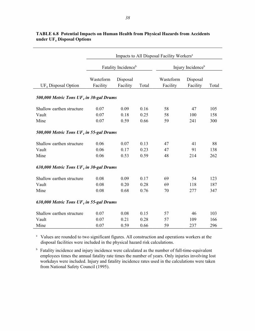
38
TABLE 6.8 Potential Impacts on Human Health from Physical Hazards from Accidentsunder UF4 Disposal Options
Impacts to All Disposal Facility Workersa
Fatality Incidenceb Injury Incidenceb
Wasteform Disposal Wasteform DisposalUF4 Disposal Option Facility Facility Total Facility Facility Total
500,000 Metric Tons UF4 in 30-gal Drums
Shallow earthen structure 0.07 0.09 0.16 58 47 105Vault 0.07 0.18 0.25 58 100 158Mine 0.07 0.59 0.66 59 241 300
500,000 Metric Tons UF4 in 55-gal Drums
Shallow earthen structure 0.06 0.07 0.13 47 41 88Vault 0.06 0.17 0.23 47 91 138Mine 0.06 0.53 0.59 48 214 262
630,000 Metric Tons UF4 in 30-gal Drums
Shallow earthen structure 0.08 0.09 0.17 69 54 123Vault 0.08 0.20 0.28 69 118 187Mine 0.08 0.68 0.76 70 277 347
630,000 Metric Tons UF4 in 55-gal Drums
Shallow earthen structure 0.07 0.08 0.15 57 46 103Vault 0.07 0.21 0.28 57 109 166Mine 0.07 0.59 0.66 59 237 296
a Values are rounded to two significant figures. All construction and operations workers at thedisposal facilities were included in the physical hazard risk calculations.
b Fatality incidence and injury incidence were calculated as the number of full-time-equivalentemployees times the annual fatality rate times the number of years. Only injuries involving lostworkdays were included. Injury and fatality incidence rates used in the calculations were takenfrom National Safety Council (1995).

39
a mean aerodynamic diameter of 10 :m or less, resulting from construction of the wasteform facilityand from construction of disposal areas/facilities, are shown in Table 6.9 for disposal of630,000 metric tons of UF4 in 30-gal drums. The criteria pollutant emissions from construction andoperation of the other disposal facilities are related to those in Table 6.9 by the scaling factors listedin Table 6.10. Scaling factors for non-PM10 (CO, HC, NOx) and PM10 pollutants are quite different;thus, scaling factors are listed separately in Table 6.10 for these two categories. For example, the COemissions from operations involving the disposal of 630,000 metric tons of UF4 in 30-gal drums invaults would be 2.91 × 1.18 tons/yr, or 3.43 tons/yr. For the same option, the PM10 emissions wouldbe 0.039 × 22.7 tons/yr, or 0.89 ton/yr.
The highest concentration increments were estimated on the basis of the highest emissionsfor each of the construction and operation phases. In general, fugitive dust emissions, resulting fromsoil excavation and earth-moving activities, would be predominant over other criteria pollutantsduring the construction period. Potential air quality impacts were estimated on the basis of thehighest PM10 emissions (28.60 tons/yr or 25.95 metric tons/yr) from the construction of facilities:mines for disposal of 630,000 metric tons of UF4 in 30-gal drums (as shown in the upper part ofTable 6.11). At a distance of 2,460 ft (750 m) from the release point, the maximum 24-hour andannual PM10 concentration increments during construction might be as large as 27% of the150-:g/m3 standard and 13% of the 50-:g/m3 standard. Concentration increments would be muchlower at the potential nearest residence, which is generally far from the site boundaries. Theconcentration increments for the other criteria pollutants (CO, SOx, and NOx) and HC would be0.068, 0.32, 0.021, and 0.026 times as large, respectively, as those for PM10. Because the othercriteria pollutant concentration increments would be a smaller fraction of their standards than PM10
would be, ambient air quality impacts associated with construction would be minor.
TABLE 6.9 Pollutant Emissions from Construction ActivitiesAssociated with Disposal Facilities for 630,000 Metric Tons ofUF4 Disposed of in 30-Gallon Drums
Pollutant Emissions from Construction (tons/yr)
PollutantWasteform
FacilityShallow Earthen
Structure Vault Mine
CO 0.801 2.60 1.18 1.96HC 0.305 0.988 0.452 0.75NOx 3.71 12.1 5.46 9.11SOx 0.244 0.792 0.363 0.60PM10 6.07 17.0 22.7 28.6

40
TABLE 6.10 Scaling Factors for Criteria Pollutant Emissions from Construction andOperations under UF4 Disposal Options, Relative to Emissions from Construction Associatedwith Disposal Facilities for 630,00 Metric Tons of UF4 Disposed of in 30-Gallon Drums
Inventory Drum Scaling Factors
UF4 Disposal OptionAmount
(metric tons)Size (gal) Construction Operations
Wasteform facility 630,000 30 1.00 (1.00)a 0.012 (5.3E-04)a
630,000 55 0.76 (0.80) 0.011 (4.7E-04)500,000 30 0.98 (0.98) 0.012 (5.2E-04)500,000 55 0.76 (0.80) 0.011 (4.7E-04)
Shallow earthen structure 630,000 30 1.00 (1.00) 1.01 (0.040)630,000 55 0.55 (0.84) 0.56 (0.022)500,000 30 0.99 (0.80) 1.01 (0.040)500,000 55 0.55 (0.67) 0.56 (0.022)
Vault 630,000 30 1.00 (1.00) 2.91 (0.039)630,000 55 1.11 (1.20) 3.23 (0.043)500,000 30 1.00 (0.80) 2.91 (0.039)500,000 55 1.11 (1.00) 3.23 (0.043)
Mine 630,000 30 1.00 (1.00) 0.082 (1.17E-03)630,000 55 0.80 (0.81) 0.055 (7.83E-04)500,000 30 0.84 (0.85) 0.082 (7.41E-04)500,000 55 0.67 (0.69) 0.055 (4.97E-04)
a Scaling factors for PM10 are in parentheses.
Except for NOx emissions from construction, NOx emissions from engine exhaust andbuilding space heating during operations would be the largest of all criteria pollutants. Potential airquality impacts were estimated on the basis of the highest NOx emissions (17.62 tons/yr or15.98 metric tons/yr) from facility operations: vaults for disposal of the original or new inventoryin 55-gal drums (as shown in the lower part of Table 6.11). At a distance of 2,460 ft (750 m) fromthe release point, the maximum annual NOx concentration increments during operation might be aslarge as 11% of the 100-:g/m3 standard. The other concentration increments for the criteria pollutant(CO, SOx, and PM10) and HC emissions would be 0.22, 0.067, 0.055, and 0.083 times as large,respectively, as those for NOx. Because the impacts of all of these other pollutants relative to theirstandards would be less than that of NOx, potential air quality impacts associated with operationswould be minor.

41
TABLE 6.11 Maximum Concentrations at Three Receptor Distances Resulting from theConstruction of a Mine and from the Operation of Vaults
Maximum Concentration (:g/m3)Distance from Emitter to
Receptor (m) in Dry Setting 1-h Avg 3-h Avg 8-h Avg 24-h Avg Annual Avg
Constructiona 750 470–500 170–200 79–110 32–41 3.8–6.71,000 380–410 150–180 64–85 25–32 2.4–4.41,500 270–280 85–100 41–56 16–20 1.3–2.3
Operationsb 750 300–490 110–240 50–130 21–55 2.3–111,000 240–370 96–160 42–86 16–33 1.5–4.31,500 170–230 55–81 26–48 10–19 0.76–1.5
a Based on PM10 emissions from 630,000 metric tons of UF4 in 30-gal drums in a mine.b Based on NOx emissions from 630,000 metric tons of UF4 in 55-gal drums in a vault.
Construction and operations would occur simultaneously for the vault and shallow earthenstructure disposal options. (Construction for the mined cavity option would occur before operations.)The combined construction and operations emissions might result in no increase in PM10 emissionsand a maximum increase of 38% in NOx emissions over maximum operation emissions.Accordingly, the maximum combined construction and operations emissions might result in annualNOx concentration increment as large as 15 :g/m3 at 2,460 ft (750 m), which is still well below the100 :g/m3 standard.
Uranium emissions associated with operation of the wasteform facility would be expected
to be negligible because there would be no uranium processing under normal conditions.
No quantitative estimate was made of the impacts on ozone conditions. Ozone formationis a regional issue; it is affected by emissions in the entire area around a proposed site. The pollutantsmost relevant to ozone formation that would result from the disposal of depleted uranium oxide areHC and NOx. Later studies that would be conducted after specific technologies and sites have beenselected could evaluate the potential effects that the release of those pollutants at a proposed sitewould have on ozone by comparing those releases with the total emissions of HC and NOx in thesurrounding area. Small additional contributions to the regional totals would be unlikely to alter theozone attainment status of the region.

42
6.4 WATER AND SOIL
Because this disposal analysis is based on a generic site without a specified location ordetailed description, potential impacts to surface water, groundwater and soil could not be assessedon a site-specific basis. Nevertheless, the relative impacts would have the same ranking as that forresource needs. Tables 6.12 through 6.15 summarize the resource requirements for constructing andoperating the wasteform facility, shallow earthen structure disposal facility, vault disposal facility,and mined-cavity disposal facility, respectively. Examination of these data indicates that the rankingof facilities (largest to smallest) on the basis of resource requirements would be as follows: mine,vault, shallow earthen structure, and wasteform facility. For each facility, a secondary rankingindicates that the resources required for disposal would be consistently larger for more UF4
(630,000 versus 500,000 metric tons) and smaller containers (30 versus 55 gallons). Therefore,construction and operation of a mine would have the greatest potential for affecting water and soil;construction and operation of the shallow earthen structure would have the least.
If the disposal facility was located on a site that was large compared with the size of thefacility, and if it was near a river having a minimum flow that was large compared with annual wateruse and wastewater discharge, impacts on surface water, groundwater, and soil would be negligible.The reason is because a large site and large river could sufficiently buffer the resources to mitigatethe effects produced by construction and operation of the facility.
On the other hand, if the site or the minimum flow in the river was small relative to theresource requirements, impacts would be larger. For example, if the minimum flow in the river was500 gal/min or gpm, the net annual water withdrawal for operation of the wasteform facility thatdisposes of 630,000 metric tons of UF4 in 30-gal containers would be about 10% of the flow. Theimpact of this relative withdrawal could produce moderate impacts to existing floodplains. Similarly,if the mine disposal facility was located on a 1,000-ha (247-acre) site, moderate to large impacts onsoil permeability and erosion could result.
More detailed calculations would be performed in the next tier of analyses once a disposalfacility option would be selected. In general, impacts could be minimized by constructing andoperating a facility that would have the smallest resource requirements as compared with availableresources.

43
TABLE 6.12 Environmental Parameters for the WasteformFacility
Parameter 30-gal Drums 55-gal Drums
Disposal of 500,000 Metric Tons of UF4
Land area (ha) 1.7 1.4Disturbed area (ha) 1.7 1.4Water
Construction (106 L) 3.3 2.7Operations (106 L/yr) 0.62 0.52
WastewaterConstruction (m3) 4,300 3,100Operations (m3/yr) 986 859
Excavated material (m3) 9,550 7,550
Disposal of 630,000 Metric Tons of UF4
Land area (ha) 1.7 1.4Disturbed area (ha) 1.7 1.4Water
Construction (106 L) 3.4 2.7Operations (106 L/yr) 0.63 0.52
WastewaterConstruction (m3) 4,400 3,100Operations (m3/yr) 988 860
Excavated material (m3) 9,750 7,550
6.5 SOCIOECONOMICS
The socioeconomic impacts of each UF4 disposal option are discussed here for the peak yearof construction and first year of operations. Impacts from each facility are presented separately.However, because the wasteform facility would process waste at the disposal site for each disposaloption, the total impact can be determined by summing the impact of the wasteform facility and theimpact of each separate facility option.
The impacts from each disposal option for disposal of both the 500,000 and the630,000 metric tons of UF4 in both container sizes on direct employment and income are shown inTable 6.16. Construction of a wasteform facility for disposal of the 500,000 metric tons of UF4 in30-gal containers would create 110 direct jobs and $4.2 million in direct income. Disposal in 55-galcontainers would create 80 direct jobs and $2.9 million in direct income. Operation of the wasteform

44
TABLE 6.13 Environmental Parameters for a Shallow Earthen Structure
Parameter 30-gal Drums 55-gal Drums
Disposal of 500,000 Metric Tons of UF4
Land area (ha) 20.6 17.4Disturbed area (ha) 18.7 15.7Water
Construction (106 L) 0.28 0.27Operations (106 L/yr) 0.083 0.052
WastewaterConstruction (m3) 6,600 6,400Operations (m3/yr) NAa NA
Excavated material (m3) 1.29 × 10⁶ 1.06 × 10⁶
Disposal of 630,000 Metric Tons of UF4
Land area (ha) 25.5 21.6Disturbed area (ha) 23.4 19.7Water
Construction (106 L) 0.29 0.28Operations (106 L/yr) 0.084 0.052
WastewaterConstruction (m3) 6,900 6,600Operations (m3/yr) NA NA
Excavated material (m3) 1.65 × 10⁶ 1.36 × 10⁶
a NA = not applicable.
facility would create 40 direct jobs and produce $2.0 million in direct income if disposal was in30-gal containers, and 40 direct jobs and $1.8 million if disposal was in 55-gal containers. For the630,000 metric tons of UF4, construction of the wasteform facility would create 110 direct jobs and$4.3 million in direct income if 30-gal containers were used. If disposal was in 55-gal containers,80 direct jobs and $2.9 million in direct income would be created. Operation of the wasteformfacility would create 40 direct jobs and produce $2.0 million in direct income if disposal was in30-gal containers, and 40 direct jobs and $1.8 million if disposal was in 55-gal containers.
Construction of a shallow earthen structure for disposal of 500,000 metric tons of UF4 in30-gal containers would create 20 direct jobs and $0.9 million in direct income. Disposal in 55-galcontainers would create 20 direct jobs and $0.8 million in direct income. Operation of the shallow

45
TABLE 6.14 Environmental Parameters for a Vault
Parameter 30-gal Drums 55-gal Drums
Disposal of 500,000 Metric Tons of UF4
Land area (ha) 25.4 31.6Disturbed area (ha) 25.4 31.6Water
Construction (106 L) 59.3 65.5Operations (106 L/yr) 0.076 0.084
WastewaterConstruction (m3) 14,000 15,000Operations (m3/yr) NAa NA
Excavated material (m3) 572,000 632,000
Disposal of 630,000 Metric Tons of UF4
Land area (ha) 31.6 37.9Disturbed area (ha) 31.6 37.9Water
Construction (106 L) 74.1 81.9Operations (106 L/yr) 0.076 0.084
WastewaterConstruction (m3) 16,000 17,000Operations (m3/yr) NA NA
Excavated material (m3) 714,000 790,000
a NA = not applicable.
earthen structure would create 20 direct jobs and produce $1.2 million in direct income if 30-galcontainers were used, and 20 direct jobs and $0.9 million if 55-gal containers were used. For630,000 metric tons of UF4, construction of the shallow earthen structure would create 20 direct jobsand $0.7 million in direct income for both container sizes. Operation of the shallow earthen structurewould create 20 direct jobs and produce $1.3 million in direct income if 30-gal containers were used,and 20 direct jobs and $1.0 million if 55-gal containers were used.
Construction of a vault for disposal of 500,000 metric tons of UF4 in 30-gal containerswould create 50 direct jobs and $1.7 million in direct income. Disposal in 55-gal containers wouldcreate 50 direct jobs and $1.9 million in direct income. Operation of the vault facility would create50 direct jobs and produce $2.7 million in direct income if 30-gal containers were used, and 40 direct

46
TABLE 6.15 Environmental Parameters for a Mined Cavity
Parameter 30-gal Drums 55-gal Drums
Disposal of 500,000 Metric Tons of UF4
Land area (ha) 236 168Disturbed area (ha) 236 168Water
Construction (106 L) 16.7 14.0Operations (106 L/yr) 3.09 2.33
WastewaterConstruction (m3) 58,000 52,000Operations (m3/yr) NAa NA
Excavated material (m3) 1.22 × 10⁶ 990,000
Disposal of 630,000 Metric Tons of UF4
Land area (ha) 310 220Disturbed area (ha) 310 220Water
Construction (106 L) 19.4 16.1Operations (106 L/yr) 3.10 2.33
WastewaterConstruction (m3) 66,000 57,000Operations (m3/yr) NA NA
Excavated material (m3) 1.44 × 10⁶ 1.16 × 10⁶
a NA = not applicable.
jobs and $2.1 million if 55-gal containers were used. For 630,000 metric tons of UF4, constructionof the vault facility would create 40 direct jobs and $1.6 million in direct income if 30-gal containerswere used, and 40 direct jobs and $1.7 million in direct income if 55-gal containers were used.Operation of the vault facility would create 50 direct jobs and produce $2.7 million in direct incomeif 30-gal containers were used, and 40 direct jobs and $2.1 million if 55-gal containers were used.
Construction of a mined cavity for disposal of 500,000 metric tons of UF4 in 30-galcontainers would create 760 direct jobs and $25.5 million in direct income. Disposal in 55-galcontainers would create 680 direct jobs and $22.8 million in direct income. Operation of the minedcavity would create 30 direct jobs and produce $1.7 million in direct income if 30-gal containerswere used, and 30 direct jobs and $1.5 million if 55-gal containers were used. For the 630,000 metrictons of UF4, construction of the mined cavity would create 860 direct jobs and $28.9 million in direct

47
TABLE 6.16 Socioeconomic Impacts from UF4 Disposal Options
Disposal of 500,000 Metric Tons of UF4 per Phase and Drum Size
Disposal of 630,000 Metric Tons of UF4 per Phase and Drum Size
Constructiona Operationsb Constructiona Operationsb
UF4 Disposal Option andSocioeconomic Parameters 30-gal 55-gal 30-gal 55-gal 30-gal 55-gal 30-gal 55-gal
Wasteform facilityDirect employmentc
(no. of persons)110 80 40 40 110 80 40 40
Direct income (106 year 2000 $)
4.2 2.9 2.0 1.8 4.3 2.9 2.0 1.8
Shallow earthen structureDirect employmentc
(no. of persons)20 20 20 20 20 20 20 20
Direct income (106 year 2000 $)
0.9 0.8 1.2 0.9 0.7 0.7 1.3 1.0
VaultDirect employmentc
(no. of persons)50 50 50 40 40 40 50 40
Direct income (106 year 2000 $)
1.7 1.9 2.7 2.1 1.6 1.7 2.7 2.1
MineDirect employmentc
(no. of persons)760 680 30 30 860 740 30 30
Direct income (106 year 2000 $)
25.5 22.8 1.7 1.5 28.9 24.8 1.8 1.5
a Impacts are from the peak year of construction: Year 3 for the wasteform facility, Year 5 or 6 for the mine.Impacts from constructing the shallow earthen structure or the vault would be identical in each year of the life ofthe facility, with construction continuing concurrently with waste placement.
b Impacts are for the first year of operation.c For operations, direct employment includes those persons directly associated with operations, such as chemical
operators, foremen, and technicians, plus their line supervision. Clerical and health physics support is alsoincluded. The values presented here represent the estimated number of workers for a “greenfield” site, where anew disposal facility would be constructed in support of depleted UF4 disposal. The number of additionalworkers that would be required at an already existing disposal site would, in general, be less than those shownabove.
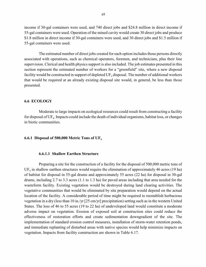
48
income if 30-gal containers were used, and 740 direct jobs and $24.8 million in direct income if55-gal containers were used. Operation of the mined cavity would create 30 direct jobs and produce$1.8 million in direct income if 30-gal containers were used, and 30 direct jobs and $1.5 million if55-gal containers were used.
The estimated number of direct jobs created for each option includes those persons directlyassociated with operations, such as chemical operators, foremen, and technicians, plus their linesupervision. Clerical and health physics support is also included. The job estimates presented in thissection represent the estimated number of workers for a “greenfield” site, where a new disposalfacility would be constructed in support of depleted UF4 disposal. The number of additional workersthat would be required at an already existing disposal site would, in general, be less than thosepresented.
6.6 ECOLOGY
Moderate to large impacts on ecological resources could result from constructing a facilityfor disposal of UF4. Impacts could include the death of individual organisms, habitat loss, or changesin biotic communities.
6.6.1 Disposal of 500,000 Metric Tons of UF4
6.6.1.1 Shallow Earthen Structure
Preparing a site for the construction of a facility for the disposal of 500,000 metric tons ofUF4 in shallow earthen structures would require the elimination of approximately 46 acres (19 ha)of habitat for disposal in 55-gal drums and approximately 55 acres (22 ha) for disposal in 30-galdrums, including 2.7 to 3.3 acres (1.1 to 1.3 ha) for paved areas including that area needed for thewasteform facility. Existing vegetation would be destroyed during land clearing activities. Thevegetative communities that would be eliminated by site preparation would depend on the actuallocation of the facility. A considerable period of time might be required to reestablish herbaciousvegetation in a dry (less than 10 in./yr [25 cm/yr] precipitation) setting such as in the western UnitedStates. The loss of 46 to 55 acres (19 to 22 ha) of undeveloped land would constitute a moderateadverse impact on vegetation. Erosion of exposed soil at construction sites could reduce theeffectiveness of restoration efforts and create sedimentation downgradient of the site. Theimplementation of standard erosion control measures, installation of storm-water retention ponds,and immediate replanting of disturbed areas with native species would help minimize impacts onvegetation. Impacts from facility construction are shown in Table 6.17.

49
TABLE 6.17 Impacts on Ecological Resources from UF4 Disposal Facility Construction
Impacts from Disposal Facility Construction per UF4 Disposal Optiona
Resource Shallow Earthen Structure Vault Mine
Disposal of 500,000 Metric Tons of UF4
Vegetation Loss of 46 to 55 acres,moderate adverse impact
Loss of 67 to 82 acres,moderate adverse impact
Loss of 418 to 587 acres,large adverse impact
Wildlife Loss of 46 to 55 acres,moderate adverse impact
Loss of 67 to 82 acres,moderate adverse impact
Loss of 418 to 587 acres,large adverse impact
Aquatic Potential reduction in waterquality, habitat
Potential reduction in waterquality, habitat
Potential reduction in waterquality, habitat
Wetlands Potential loss, degradation Potential loss, degradation Potential loss, degradation
Protectedspecies
Potential destruction, habitat loss Potential destruction, habitat loss Potential destruction, habitat loss
Disposal of 630,000 Metric Tons of UF4
Vegetation Loss of 57 to 67 acres,moderate adverse impact
Loss of 82 to 97 acres,moderate to large adverse impact
Loss of 547 to 770 acres,large adverse impact
Wildlife Loss of 57 to 67 acres,moderate adverse impact
Loss of 82 to 97 acres,moderate to large adverse impact
Loss of 547 to 770 acres,large adverse impact
Aquatic Potential reduction in waterquality, habitat
Potential reduction in waterquality, habitat
Potential reduction in waterquality, habitat
Wetlands Potential loss, degradation Potential loss, degradation Potential loss, degradation
Protectedspecies
Potential destruction, habitat loss Potential destruction, habitat loss Potential destruction, habitat loss
a All acreages include the wasteform facility.
Wildlife would be disturbed by land clearing, noise, and human presence. Wildlife withrestricted mobility, such as burrowing species or juveniles of nesting species, would be destroyedduring land clearing activities. Mobile individuals would relocate to adjacent available areas withsuitable habitat. Population densities and competition would increase in these areas, potentiallyreducing the chances of survival or reproductive capacity of displaced individuals. Some wildlifespecies would probably recolonize replanted areas near the disposal facility after the completion ofconstruction. However, habitat use in the vicinity of the facility might be reduced for some speciesas a result of the construction of a perimeter fence. In summary, the loss of up to 55 acres (22 ha) ofhabitat as a result of the construction of a facility for disposal of 500,000 metric tons of UF4 inshallow earthen structures would be considered a moderate adverse impact on wildlife.

50
Wetlands could be affected by filling or draining during construction. In addition, alterationof surface water runoff patterns, soil compaction, or groundwater flow could occur if the disposalfacility was located adjacent to wetland or aquatic habitats. However, impacts would be minimizedby maintaining a buffer area around wetlands and aquatic habitats during construction. Unavoidableimpacts on wetlands would require a Clean Water Act Section 404 permit, which might stipulatemitigative measures. Additional permitting might be required by state agencies. Depending on thefacility location, water withdrawal from surface water or groundwater, as well as wastewaterdischarge, could potentially alter water levels. These altered levels could, in turn, affect aquaticecosystems, including wetlands, especially those located along the periphery of these surface waterbodies.
Before construction of a disposal facility, a survey for state and federally listed threatened,endangered, or candidate species or species of special concern would be conducted so that impactson these species could be avoided, if possible. If impacts were unavoidable, appropriate mitigationmeasures could be developed.
Facility accidents, as discussed in Section 6.3.2, could result in adverse impacts toecological resources. The affected species and degree of impact would depend on a number offactors, such as location of the accident, season, and meteorological conditions.
6.6.1.2 Vault
The construction and operation of a facility for the disposal of 500,000 metric tons of UF4
in vaults would generally result in impacts similar to those associated with shallow earthenstructures. However, the size of the facility and area of disturbance for vault disposal would belarger. Disposal in vaults would require the disturbance of approximately 67 to 82 acres (27 to 33 ha)of habitat, depending on the packaging option, including 9.5 to 11.6 acres (3.8 to 4.7 ha) for pavedareas, including that area needed for the wasteform facility. This disposal option would elevate thesoil surface as a result of the placement of excavated material and reduction in soil permeability. Thedecrease in soil moisture would make it difficult to reestablish vegetation and would delay theestablishment of native plant communities. This disposal option would result in a moderate adverseimpact on existing vegetation and wildlife. Reestablishment of native vegetation over such a largearea would be especially difficult in a dry setting; a considerable period of time might be required.
6.6.1.3 Mine
The construction and operation of a facility for the disposal of 500,000 metric tons of UF4
in a mine would generally result in impacts similar to those associated with vaults. However, themine option would require the disturbance of approximately 418 to 587 acres (169 to 238 ha),

51
depending on the packaging option, including 27.9 to 30.5 acres (11 to 12 ha) for paved areas,including that area needed for the wasteform facility. This disposal option would elevate the soilsurface and reduce soil permeability. The excavated material would primarily consist of rockremoved from the drifts and ramps. The consequent decrease in surface soil moisture would makeit difficult to reestablish vegetation and would delay the establishment of native plant communities.This disposal option would result in a large adverse impact on existing vegetation and wildlife.Reestablishment of native vegetation over such a large area would be especially difficult in a drysetting; a considerable period of time might be required.
6.6.2 Disposal of 630,000 Metric Tons of UF4
The construction and operation of a facility for the disposal of 630,000 metric tons of UF4
would generally result in the same types of impacts as those associated with the disposal of500,000 metric tons of UF4; however, the facility sizes would be larger. A shallow earthen structuredisposal facility for 630,000 metric tons of UF4 would eliminate approximately 57 to 67 acres (23to 27 ha) of habitat, including the area for the wasteform facility. This habitat loss would result ina moderate adverse impact on vegetation and wildlife. Disposal in vaults would eliminateapproximately 82 to 97 acres (33 to 39 ha) of habitat, including the area for the wasteform facility.This loss would result in a moderate to large adverse impact on vegetation and wildlife. A minedisposal facility would disturb approximately 547 to 770 acres (221 to 312 ha) of habitat, includingthe area for the wasteform facility. This habitat disturbance would result in a large adverse impacton vegetation and wildlife.
6.7 WASTE MANAGEMENT
Waste generated during the construction of the disposal facility would be typical of a largeconstruction project. It would include construction debris such as concrete and scrap steel as wellas sanitary waste from the labor force. No radioactive wastes would be generated during theconstruction of the wasteform facility or any of the three proposed disposal facilities becauseradioactive materials would not be used and the site would be uncontaminated. Construction wastesare listed in Table 6.18. Table 6.19 lists the various hazardous and nonhazardous wastes expectedfrom the different disposal options. Estimates for the original inventory (500,000 metric tons) as wellas the larger inventory (630,000 metric tons) of depleted UF4 are included in the table. The wastegenerated during the construction of any of the disposal facilities would represent a negligible impacton DOE’s waste management capabilities.
Because UF4 forms a corrosive product in the presence of water, it is not suitable forgrouting. Depleted UF4 is a Class A waste under NRC’s classification scheme. To be classified asa Class A waste, the waste must exhibit structural stability under expected disposal conditions. Such

52
TABLE 6.18 Estimated Construction Wastes Generated under UF4 Disposal Options
Disposal of 500,000 Metric Tons of UF4 per Drum Size Disposal of 630,000 Metric Tons of UF4 per Drum Size
30-gal 55-gal 30-gal 55-galUF4 Disposal Option
and Waste Type Annuala Total Annuala Total Annuala Total Annuala Total
Wasteform facilityHazardous solids (m3) 4.9 14.8 3.5 10.6 4.9 15.3 3.5 10.6Hazardous liquids (m3) 10.0 29.9 7.1 21.3 10.0 30.9 7.1 21.3Nonhazardous solids
Concrete (m3) 36.7 110 30 90 36.7 110 30 90Steel (metric tons) 0.6 1.7 0.5 1.4 0.6 1.8 0.5 1.4Other (m3) 297 890 230 690 297 920 230 690
Nonhazardous liquidsSanitary (m3) 1,400 4,300 1,000 3,100 1,400 4,400 1,000 3,100Other (m3) 640 1,900 450 1,400 640 2,000 450 1,400
Shallow earthen structureHazardous solids (m3) 1.2 23 1.1 22 1.0 24 0.9 23Hazardous liquids (m3) 2.3 46 2.3 45 2.0 48 1.8 46Nonhazardous solids
Concrete (m3) 0 0 0 0 0 0 0 0Steel (metric tons) 0 0 0 0 0 0 0 0Other (m3) 0 0 0 0 0 0 0 0
Nonhazardous liquidsSanitary (m3) 330 6,600 320 6,400 274 6,900 264 6,600Other (m3) 145 2,900 145 2,900 124 3,100 116 2,900
VaultHazardous solids (m3) 2.4 47 2.6 51 2.2 54 2.3 58Hazardous liquids (m3) 4.8 96 5.1 102 4.4 110 4.6 116Nonhazardous solids
Concrete (m3) 133 2,660 147 2,940 133 3,330 147 3,680Steel (metric tons) 1.1 22.0 1.2 24.5 1.1 28.0 1.2 30.5Other (m3) 1,050 21,000 1,200 24,000 1,100 27,000 1,200 29,000
Nonhazardous liquidsSanitary (m3) 700 14,000 750 15,000 640 16,000 680 17,000Other (m3) 305 6,100 325 6,500 280 7,000 296 7,400
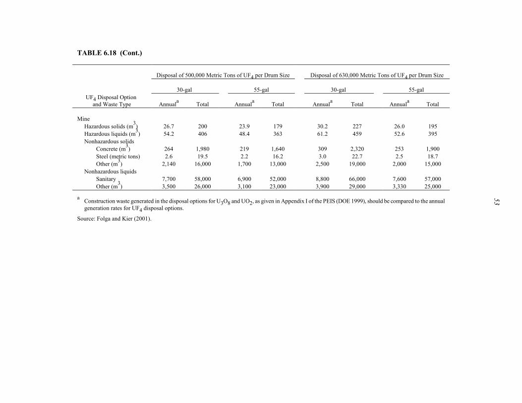
53
TABLE 6.18 (Cont.)
Disposal of 500,000 Metric Tons of UF4 per Drum Size Disposal of 630,000 Metric Tons of UF4 per Drum Size
30-gal 55-gal 30-gal 55-galUF4 Disposal Option
and Waste Type Annuala Total Annuala Total Annuala Total Annuala Total
MineHazardous solids (m3) 26.7 200 23.9 179 30.2 227 26.0 195Hazardous liquids (m3) 54.2 406 48.4 363 61.2 459 52.6 395Nonhazardous solids
Concrete (m3) 264 1,980 219 1,640 309 2,320 253 1,900Steel (metric tons) 2.6 19.5 2.2 16.2 3.0 22.7 2.5 18.7Other (m3) 2,140 16,000 1,700 13,000 2,500 19,000 2,000 15,000
Nonhazardous liquidsSanitary 7,700 58,000 6,900 52,000 8,800 66,000 7,600 57,000Other (m3) 3,500 26,000 3,100 23,000 3,900 29,000 3,330 25,000
a Construction waste generated in the disposal options for U3O8 and UO2, as given in Appendix I of the PEIS (DOE 1999), should be compared to the annualgeneration rates for UF4 disposal options.
Source: Folga and Kier (2001).
54
TABLE 6.19 Estimated Annual Radioactive and Nonhazardous Waste Streams from Wasteform Facility Operations
Annual Waste Stream (m3) per UF4 Inventory
500,000 Metric Tons (20 yr) 630,000 Metric Tons (25 yr)
Waste Stream Treatability Category 30-gal Drums 55-gal Drums 30-gal Drums 55-gal Drums
Facility waste (product) (LLW) NAa 7,810 7,810 7,870 7,870HEPA filters (LLW) Noncombustible, compactable LLW 23.8 23.8 23.8 23.8Damaged drums (LLW) Surface-contaminated metal LLW 7.8 7.8 7.9 7.9Other LLW Combustible solid LLW 47.6 26.2 47.9 26.5Inorganic solutions (LLMW) Liquid LLMW 0.26 0.18 0.26 0.18Nonhazardous (sanitary) wastes NA 986 859 988 860Nonhazardous (other) wastes NA 78 68 78 68Recyclable wastes NA 31 27 31 27
a NA = not applicable.
Source: Folga and Kier (2001).

55
stability can be achieved by placing the waste in a strong disposal container such as 30-gal or 55-galdrums. Under these conditions, the wasteform facility would consist of a product receiving,repackaging (where necessary), and shipping warehouse, which would include an administrationbuilding. The construction and operation period assumed for the shallow earthen structure and vaultdisposal facilities is 20 years for the original inventory (500,000 metric tons) and 25 years for thenew inventory (630,000 metric tons); the construction period assumed is 7.5 years for the minedcavity disposal facility for both inventories, with an operational period of 20 years for the originalinventory and 25 years for the new inventory. Table 6.20 lists the drum throughputs at the wasteformfacility for each disposal option for both inventories. Table 6.19 lists the annual operational wastesfrom the wasteform facility for the original inventory (20-yr operation) and the new inventory (25-yroperation).
Estimates of the amount of LLW to be disposed of at DOE waste management disposalfacilities depend critically upon the time frame under consideration and the types of waste. The FinalWaste Management Programmatic Environmental Impact Statement (WM PEIS; DOE 1997)estimates that 1,060,000 m3 of LLW will be disposed of between 1995 and 2014. This estimate doesnot include any LLW from environmental restoration activities or facility stabilization activities. Amore appropriate value is reported in The 1996 Baseline Environmental Management Report(BEMR) (DOE 1996), which estimates the total amount of LLW for treatment at waste managementfacilities to be 3,400,000 m3. This estimate is for 75 years and includes contributions fromenvironmental restoration and facility stabilization programs.
The majority of environmental restoration wastes are expected to be generated between2003 and 2033, approximately the correct time frame to compare with the depleted UF4 wastes.Adjustments must be made to the BEMR estimate to convert treatment volumes into disposal
TABLE 6.20 Variations in Wasteform Facility Operations under UF4Disposal Options
Annual Throughput Quantity (no. of drums/yr) per Inventory
DrumSize (gal) UF4 Disposal Option
500,000Metric Tons UF4
630,000Metric Tons UF4
30 Shallow earthen structure 68,650 69,16055 Shallow earthen structure 37,450 37,72030 Vault 68,650 69,16055 Vault 37,450 37,72030 Mine 183,100 230,50055 Mine 99,900 125,700

56
volumes. Both reductions and expansions in volume would occur during waste treatment andgrouting, depending on the relative amounts of the different types of waste. On the basis of the WMPEIS analysis (DOE 1997), the BEMR estimate of the disposal volume was adjusted to4,250,000 m3. The total volumes of LLW from disposal of depleted uranium as UF4 were comparedwith the total estimated volume of LLW for disposal from all DOE waste management activities(including environmental restoration waste). Disposal volumes were compared as total volume incubic meters because disposal facilities would not typically have throughput limitations but wouldbe limited in the total volume of waste that they could accept.
For the case of UF4 with a waste volume of 7,810 m3/yr, the total disposal volume wouldbe 156,000 m3 (7,810 m3 × 20-yr operation). This volume would add about 3.7% to the estimatedtotal DOE LLW disposal volume of about 4,250,000 m3. Using a similar approach to the newinventory would add about 4.6% to the estimated total DOE LLW disposal volume. Secondary wastestreams of LLW generated in the disposal of UF4 (see Table 6.19) would have only a negligibleimpact on DOE LLW disposal capabilities. The amount of low-level mixed waste (LLMW) fromdepleted UF4 disposal added to the total nationwide LLMW load would be negligible (less than 1%).
Overall, the disposal options would generate appreciable amounts of waste for disposal inDOE facilities. Within the context of the total amount of LLW undergoing disposal in DOEfacilities, these wastes would have a small impact on DOE’s total waste management disposalcapabilities.
6.8 RESOURCE REQUIREMENTS
Resource requirements for the disposal options were estimated for construction andoperations. The materials required for monitoring groundwater and disposal cell performance wouldbe expected to be minor.
Materials and utilities required for construction and operation of the shallow earthenstructure, vault, and mine options are listed in Tables 6.21 to 6.29. In general, the amounts ofresources needed are directly related to the volume of waste to be disposed of. The total quantitiesof commonly used construction materials needed are not expected to be significant and would becomparable to those needed to build a multistory building. No specialty materials (e.g., Monel orInconel) are projected to be needed for either construction or operations.
Significant quantities of electricity could be required during construction of the mine sincemost of the construction equipment is powered by electricity to avoid polluting the air in theunderground work area. Similarly, the annual amount of electricity consumed during undergroundoperations would be greater than the amount consumed in the other disposal facility options.

57
TABLE 6.21 Materials and Resources Required duringConstruction of Shallow Earthen Structure Disposal Facilitya
30-gal Drums 55-gal Drums
Item Annual Totala Annual Totala
500,000 Metric Tons of UF4
Water (106 L) 0.014 0.28 0.014 0.27Excavated material (m3) 6.44E+04 1.29E+06 5.32E+04 1.06E+06Clay (m3) 437 8,740 392 7,840Sand (m3) 2,910 5.83E+04 2,340 4.69E+04Gravel (metric tons) 122 2,440 99 1,970Electricity (MWh) 220 4,410 185 3,700Diesel fuel (L) 5.68E+04 1.14E+06 4.69E+04 9.38E+05
630,000 Metric Tons of UF4
Water (106 L) 0.12 0.29 0.011 0.28Excavated material (m3) 6.58E+04 1.65E+06 5.44E+04 1.36E+06Clay (m3) 452 11,300 406 1.01E+04Sand (m3) 3,060 7.65E+04 2,480 6.20E+04Gravel (metric tons) 128 3,200 104 2,600Electricity (MWh) 222 5,560 186 4,640Diesel fuel (L) 5.82E+04 1.45E+06 4.81E+04 1.20E+06
a Totals are for 20 years of operations for 500,000 metric tons of UF4 and 25 years ofoperations for 630,000 metric tons of UF4.
TABLE 6.22 Resources Required during Operations of ShallowEarthen Structure Disposal Facility
30-gal Drums 55-gal Drums
Item Annual Totala Annual Totala
500,000 Metric Tons of UF4
Water (106 L) 0.083 1.66 0.052 1.04Electricity (MWh) 1,030 2.06E+04 762 1.52E+04Diesel fuel (L) 1.48E+05 2.97E+06 8.21E+04 1.64E+06
630,000 Metric Tons of UF4
Water (106 L) 0.084 2.09 0.052 1.31Electricity (MWh) 1,030 2.58E+04 765 1.91E+04Diesel fuel (L) 1.49E+05 3.73E+06 8.26E+04 2.07E+06
a Totals are for 20 years of operations for 500,000 metric tons of UF4 and 25years of operations for 630,000 metric tons of UF4.
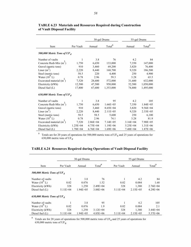
58
TABLE 6.23 Materials and Resources Required during Construction of Vault Disposal Facility
30-gal Drums 55-gal Drums
Item Per Vault Annual Totala Annual Totala
500,000 Metric Tons of UF4
Number of vaults 1 3.8 76 4.2 84Concrete Redi-Mix (m3) 1,750 6,650 133,000 7,350 147,000Gravel (metric tons) 910 3,460 69,200 3,820 76,400Liner (m2) 2,220 8,440 168,700 9,320 186,500Steel (metric tons) 58.5 220 4,400 250 4,900Water (106 L) 0.78 2.96 59.3 3.28 65.5Excavated material (m3) 7,520 28,600 572,000 31,600 632,000Electricity (kWh) 12,500 47,500 950,000 52,500 1,050,000Diesel fuel (L) 17,800 67,600 1,353,000 74,800 1,495,000
630,000 Metric Tons of UF4
Number of vaults 1 3.8 95 4.2 105Concrete Redi-Mix (m3) 1,750 6,650 1.66E+05 7,350 1.84E+05Gravel (metric tons) 910 3,460 8.65E+04 3,820 9.56E+04Liner (m2) 2,220 8,440 2.11E+05 9,320 2.33E+05Steel (metric tons) 58.5 58.5 5,600 250 6,100Water (106 L) 0.78 2.96 74.1 3.28 81.9Excavated material (m3) 7,520 2.86E+04 7.14E+05 3.16E+04 7.90E+05Electricity (kWh) 1.25E+04 4.75E+04 1.19E+06 5.25E+04 1.31E+06Diesel fuel (L) 1.78E+04 6.76E+04 1.69E+06 7.48E+04 1.87E+06a Totals are for 20 years of operations for 500,000 metric tons of UF4 and 25 years of operations for
630,000 metric tons of UF4.
TABLE 6.24 Resources Required during Operations of Vault Disposal Facility
30-gal Drums 55-gal Drums
Item Per Vault Annual Totala Per Vault Annual Totala
500,000 Metric Tons of UF4
Number of vaults 1 3.8 76 1 4.2 84Water (106 L) 0.02 0.076 1.52 0.02 0.084 1.68Electricity (kWh) 328 1,250 2.49E+04 328 1,380 2.76E+04Diesel fuel (L) 5.11E+04 1.94E+05 3.88E+06 5.11E+04 2.15E+05 4.29E+06
630,000 Metric Tons of UF4
Number of vaults 1 3.8 95 1 4.2 105Water (106 L) 0.02 0.076 1.9 0.02 0.084 2.1Electricity (kWh) 328 1,250 3.12E+04 328 1,380 3.44E+04Diesel fuel (L) 5.11E+04 1.94E+05 4.85E+06 5.11E+04 2.15E+05 5.37E+06a Totals are for 20 years of operations for 500,000 metric tons of UF4 and 25 years of operations for
630,000 metric tons of UF4.
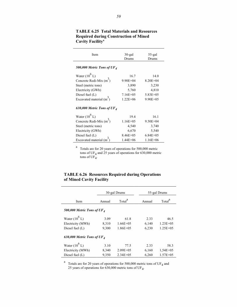
59
TABLE 6.25 Total Materials and ResourcesRequired during Construction of Mined Cavity Facilitya
Item 30-galDrums
55-galDrums
500,000 Metric Tons of UF4
Water (106 L) 16.7 14.0 Concrete Redi-Mix (m3) 9.90E+04 8.20E+04 Steel (metric tons) 3,890 3,230 Electricity (GWh) 5,760 4,810 Diesel fuel (L) 7.16E+05 5.83E+05 Excavated material (m3) 1.22E+06 9.90E+05
630,000 Metric Tons of UF4
Water (106 L) 19.4 16.1 Concrete Redi-Mix (m3) 1.16E+05 9.50E+04 Steel (metric tons) 4,540 3,740 Electricity (GWh) 6,670 5,540 Diesel fuel (L) 8.46E+05 6.84E+05 Excavated material (m3) 1.44E+06 1.16E+06
a Totals are for 20 years of operations for 500,000 metrictons of UF4 and 25 years of operations for 630,000 metrictons of UF4.
TABLE 6.26 Resources Required during Operations of Mined Cavity Facility
30-gal Drums 55-gal Drums
Item Annual Totala Annual Totala
500,000 Metric Tons of UF4
Water (106 L) 3.09 61.8 2.33 46.5Electricity (MWh) 8,310 1.66E+05 6,140 1.23E+05Diesel fuel (L) 9,300 1.86E+05 6,230 1.25E+05
630,000 Metric Tons of UF4
Water (106 L) 3.10 77.5 2.33 58.3Electricity (MWh) 8,340 2.09E+05 6,160 1,54E+05Diesel fuel (L) 9,350 2.34E+05 6,260 1.57E+05
a Totals are for 20 years of operations for 500,000 metric tons of UF4 and25 years of operations for 630,000 metric tons of UF4.

60
TABLE 6.27 Total Materials andResources Required during Construction of Wasteform Facility
Item 30-galDrums
55-galDrums
500,000 Metric Tons of UF4
Water (106 L) 3.3 2.7Concrete Redi-Mix (m3) 5,591 4,286Steel (metric tons) 349 271Excavated material (m3) 9,550 7,550Electricity (MWh) 480 410Masonry brick (m2) 573 573Diesel fuel (L) 90,000 70,000
630,000 Metric Tons of UF4
Water (106 L) 3.4 2.7Concrete Redi-Mix (m3) 5,724 4,286Steel (metric tons) 357 271Excavated material (m3) 9,750 7,550Electricity (MWh) 487 410Masonry brick (m2) 573 573Diesel fuel (L) 92,000 70,000
TABLE 6.28 Total Concrete Required for Wasteform Facility
Concrete Required (m3)
Structure Floor Walls Rook Total
500,000 Metric Tons of UF4
Warehousea
30-gal drums 2,482 759 2,068 5,30855-gal drums 1,871 572 1,559 4,003
Administration bldg. 88 94 101 283
630,000 Metric Tons of UF4
Warehousea
30-gal drums 2,544 778 2,120 5,44155-gal drums 1,871 572 1,559 4,003
Administration bldg. 88 94 101 283
a Warehouse = product receiving and shipping warehouse.

61
TABLE 6.29 Resources Required during Operations of Wasteform Facility
30-gal Drums 55-gal Drums
Item Annual Totala Annual Totala
500,000 Metric Tons of UF4
Water (106 L) 0.62 12 0.52 10Natural gas, therms (1E+05 Btu) 141 2,830 112 2,240Electricity (MWh) 671 13,400 579 11,600Diesel fuel (L) 556 11,100 502 10,000
630,000 Metric Tons of UF4
Water (106 L) 0.63 16 0.52 13Natural gas, therms (1E+05 Btu) 144 3,610 112 2,800Electricity (MWh) 680 17,000 579 14,500Diesel fuel (L) 561 14,000 502 12,600
a Totals are for 20 years of operations for 500,000 metric tons of UF4 and 25 yearsof operations for 630,000 metric tons of UF4.
6.9 LAND USE
Land area requirements for each disposal option were presented in Tables 5.2 through 5.4.These data did not include acreage required for constructing any of the disposal options because thedevelopment of land would occur incrementally, and the space needed for excavation materialstorage areas, equipment staging areas, and construction material laydown areas would be availableon adjacent, undeveloped parcels. Consequently, areal needs for construction would not be greaterthan those for operations.
If the facility site selected was at or near a location that is already used for a similar purpose,land-use impacts could be reduced, because immediate access to infrastructure and utility supportwould require only minor disturbances to existing land use.
All disposal options would include a central wasteform facility where drums would bereceived from the conversion facility and prepared for disposal. Impacts on land use from thewasteform facility would be very small and limited to clearing of required land and possibly minorand temporary disruptions to contiguous land parcels. No off-site impacts would be expected.
Land-use impacts resulting from the shallow earthen structure disposal option would benegligible to moderate and limited to clearing of required land and possibly a slight increase in theamount of off-site vehicular traffic associated with construction activities. The large volume of

62
excavated material that would remain on site could, over time, result in topographical modificationsof the site. Impacts from off-site disposal would be determined during the site-specific tier ofNational Environmental Policy Act (NEPA) documentation. Other than minor, temporary impactsassociated with construction traffic, no other off-site impacts would be expected.
Because the vault facility would be constructed incrementally (10 vault blocks per year),the amount of land disturbed during a given year would be limited. Impacts from off-site disposalwould be determined during the site-specific tier of NEPA documentation.
Of all the disposal options, a mine would have the greatest potential for land-use impactsbecause it would require the largest amount of land (see Tables 5.3 and 5.4). The constructionassociated with this option could disturb adjacent parcels of land. The large volume of excavatedmaterial would be disposed of on site, probably resulting in topographical modifications of the site.The peak construction labor force could cause off-site land-use impacts, particularly if a remote sitewas chosen. Impacts could involve existing commercial land and traffic on local access roads andintersections.
6.10 OTHER IMPACTS CONSIDERED BUT NOT ANALYZED IN DETAIL
Other impacts that could occur if the disposal options considered in this report wereimplemented include impacts on cultural resources, environmental justice, the visual environment(e.g., aesthetics), recreational resources, and noise levels. Impacts could also result from thedecontamination and decommissioning of the disposal facilities. These impacts were considered butcould not be analyzed in detail without knowledge of the specific sites. These impacts could be moreappropriately addressed in later NEPA documentation when specific sites are being considered.

63
7 IMPACTS OF OPTIONS — POST-CLOSURE PHASE
This section provides a summary of the potential environmental impacts associated withthe post-closure phase of the disposal options. The post-closure phase covers a future time, wellbeyond the time any engineered disposal facility would be expected to function as designed. Post-closure impacts were evaluated because no matter how well-designed a disposal facility would be,it would still probably release uranium compounds to the environment. This condition is referred toas “failure.”
Disposal facility failure would generally occur hundreds to thousands of years in the future(assuming there was no sustained effort to maintain the facility). This failure would be caused bynatural degradation of the disposal structures over time, primarily from physical processes such asthe intrusion of water. Following failure, the release of uranium from the facility would occur veryslowly as water moved through the disposed material. This water would carry dissolved uraniumthrough the soil under the facility, eventually contaminating the groundwater. This process couldcontinue for thousands to millions of years because of the large amount of uranium in the disposalfacility and low solubility of that uranium.
In general, shallow earthen structures would be expected to contain waste material for atleast several hundred years before failure. Vaults and a mine would be expected to last even longerbefore failure, from many hundreds of years to thousands of years. However, the exact time that adisposal facility would be expected to fail is extremely difficult to predict and would depend on thedetailed facility design and site-specific conditions. Because of this uncertainty, failure was assumedto occur at the end of a period of institutional control, 100 years after closure. The post-closureimpacts were evaluated at 1,000 years after failure for all three disposal facility options.
Potential post-closure impacts were evaluated on three areas: (1) groundwater, (2) humanhealth and safety, and (3) ecological resources. Impacts on other areas would be expected to benegligible. The following general assumptions apply to the assessment of post-closure impacts:
C All disposal facilities would fail at some time in the future. Failure is definedas the release of uranium material from the disposal facility to the surroundingsoil. For consistency, failure was assumed to occur at the end of institutionalcontrol, 100 years after closure.
C The post-closure phase primarily considers potential impacts from thecontamination of groundwater and surface water. Potential impacts from thecontamination of air and soil due to erosion of the disposal facility surface arealso discussed.

64
C The impacts evaluated were those that would occur 1,000 years after thefacility failed and started to release uranium.
C For analysis of groundwater impacts, assumptions were varied to assess abroad range of possibilities with respect to movement of the uranium throughthe soil to the groundwater aquifer.
The estimated impacts associated with the post-closure phase are subject to a great deal ofuncertainty because the assessment considers an extremely long period of time and depends onpredicting the behavior of the waste material as it interacts with soil and water in a complex andchanging environment. Consequently, the estimated impacts are very dependent on the assessmentassumptions. Key assumptions include such factors as soil characteristics, water infiltration rates,depth to the underlying groundwater table, chemistry of different uranium compounds, and thelocations of future human receptors. These factors can vary widely depending on site-specificconditions. Because of these uncertainties, the assumptions were generally selected in a mannerintended to produce conservative estimates of impact, that is, the assumptions tend to overestimatethe expected impact. Changes in key disposal assumptions could yield significantly differentestimates of impact.
7.1 HUMAN HEALTH — NORMAL OPERATIONS
7.1.1 Radiological Impacts
Radiation doses and cancer risks for the post-closure phase were assessed for a hypotheticalindividual who would live at or near the disposal site after the institutional control period of the siteended. This individual was assumed to drill a well at the edge of the disposal site and use the wellwater for drinking, household purposes, irrigating plant foods and fodder, and watering livestock.Because of leaching of uranium from the disposal area to the groundwater table, the hypotheticalresident could be exposed to radiation through use of contaminated well water. Detailed discussionsof the methodologies used in radiological impact analyses are provided in Cheng et al. (1997).Additional information on the methodology and assumptions used in the groundwater analyses isprovided in Section 7.2.
The estimated groundwater concentrations involve large degrees of uncertainty because ofthe preliminary nature of facility design and the various soil properties that depend on the locationof the facility. The radiological impacts estimated by using the groundwater concentrations aresubject to a large degree of uncertainty as well. The groundwater contamination would persist formillions of years once it occurred because of the large inventory of UF4 in the disposal area. Becauseof the long decay half-lives of uranium isotopes and the continuous generation of decay products,

65
the maximum radiation dose, which could be greater than 1 rem/yr from using contaminatedgroundwater, would not be observed until sometime after 10,000 years, a time frame well beyondthat considered in this analysis. Table 7.1 lists the calculated radiation doses and cancer risks for themaximally exposed individual (MEI) 1,000 years after the failure of engineering barriers and wastecontainers. Because of the assumption that the disposal facility would be at a dry location, potentialradiation exposure would be minimal at that time, less than 3 × 10⁻⁶ mrem/yr .
In addition to the possible exposures resulting from use of contaminated groundwater,radiological impacts could be caused by external radiation and inhalation of contaminated dustparticles if all the cover materials above the disposal site were removed and if containers of UF4
disintegrated. This scenario could be caused by natural forces of erosion over long periods of timeor by human intervention (i.e., digging) to bring the waste to the surface. The associated externalradiation dose could be as high as 10 rem/yr for an individual living on the disposal site. However,the exposure would not occur until several thousand years after closure of the shallow earthenstructure or vault disposal facility, and exposure would be quite unlikely if mines were used fordisposal because a mine would be located several hundred feet below the ground surface. Detailedanalyses for this exposure scenario were not conducted because the time frame would be beyond thatconsidered in this analysis. If any exposure would occur, the radiation dose could be eliminated byadding new cover materials to the top of the waste area.
7.1.1.1 Disposal of 500,000 Metric Tons of UF4
Radiological impacts are listed in Table 7.1 for a scenario in which an individual usescontaminated groundwater. In a dry setting, because of the low water infiltration rate and the longdistance from the bottom of the disposal area to the groundwater table, the amount of radionuclidesthat would reach the groundwater table within 1,000 years would be very small.
7.1.1.2 Disposal of 630,000 Metric Tons of UF4
Potential radiation exposure from using contaminated groundwater would be slightly greaterfor disposal of 630,000 metric tons of UF4 than for disposal of 500,000 metric tons of UF4, becauseof the larger disposal area used. However, in a dry location, as was assumed for the analysis, theamount of radionuclides that would reach the groundwater table 1,000 years after failure of thedisposal facility would still be minimal. The estimated maximum radiation dose would be less than3 × 10-6 mrem/yr.

66
TABLE 7.1 Estimated Human Health Impacts to the MEI under UF4Disposal Options during the Post-Closure Phase
Radiological Impacts at 1,000 Yearsb,c Chemical Impacts
at 1,000 Yearsb,c
Option/Inventorya MEI Dose(mrem/yr)
MEI risk(LCF/yr)
MEI HazardIndexd
Disposal of 500,000 Metric Tons of UF4
Shallow earthen structure30-gal drums55-gal drums
< 2.2 × 10⁻⁸
< 2.0 × 10⁻⁸ < 1 × 10-14
< 1 × 10-14 3 × 10⁻⁹
2 × 10⁻⁹
Vault30-gal drums55-gal drums
< 2.9 × 10⁻⁸
< 3.2 × 10⁻⁸ < 1 × 10-14
< 2 × 10-14 4 × 10⁻⁹
2 × 10⁻⁹
Mine30-gal drums55-gal drums
< 2.3 × 10⁻⁶
< 2.0 × 10⁻⁶ < 1 × 10-12
< 1 × 10-12 3 × 10⁻⁷
2 × 10⁻⁷
Disposal of 630,000 Metric Tons of UF4
Shallow earthen structure30-gal drums55-gal drums
< 2.4 × 10⁻⁸
< 2.2 × 10⁻⁸ < 1 × 10-14
< 1 × 10-14 3 × 10⁻⁹
3 × 10⁻⁹
Vault30-gal drums55-gal drums
< 2.9 × 10⁻⁸
< 3.2 × 10⁻⁸ < 1 × 10-14
< 2 × 10-14 4 × 10⁻⁹
4 × 10⁻⁹
Mine30-gal drums55-gal drums
< 2.5 × 10⁻⁶
< 2.1 × 10⁻⁶ < 1 × 10-12
< 1 × 10-12 3 × 10⁻⁷
4 × 10⁻⁷
a Two inventories were considered for each option: 500,000 metric tons of UF4 and630,000 metric tons of UF4. The first inventory results from converting 560,000 metrictons of UF6 that DOE facilities generated in the past. The second inventory results fromconverting 705,000 metric tons of UF6 that both DOE generated and USEC generated.
b Impacts are reported as the maximum values, which result from considering differentsolubilities of uranium compounds that may be formed and different transport speeds ofradionuclides in the unsaturated and saturated zones. Retardation factors of 5 and 50 wereused to represent relatively mobile and immobile transport situations, respectively.Solubilities considered a range from 2.4 × 10⁻³ to 24 g/L.
c The maximally exposed individual (MEI) was assumed to live at the edge of the disposalsite and use contaminated groundwater for drinking, irrigating plant food and fodder, andfeeding livestock. The exposure pathways considered were ingestion of drinking water,plant foods, meat, and milk; and, for radiological exposures, inhalation of radon emanatingfrom household water.
d The hazard index is an indicator for potential adverse health effects other than cancer; ahazard index of greater than 1 indicates a potential for adverse health effects and a need forfurther evaluation.

67
7.1.2 Chemical Impacts
Chemical impacts during the post-closure phase were assessed for a hypothetical individualwho lives at the border of the disposal site after the institutional control period is over. As they werefor the radiological assessment, potential chemical impacts on human health were evaluated for ascenario involving a hypothetical individual who drills a well at the edge of the disposal site and usesthe well water for drinking, irrigating plant foods and fodder, and watering livestock. Leaching ofuranium from the disposal area to the groundwater table could potentially result in the hypotheticalresident being exposed to uranium from ingestion of drinking water, plant foods, meat, and milk.Risks are estimated on the basis of calculated hazard indices. Information on the exposureassumptions, health effects assumptions, reference doses used for uranium compounds, andcalculational methods used in the chemical impact analysis are provided in Appendix C of the PEIS(DOE 1999) and Cheng et al. (1997).
Potential health impacts on the general public MEI from exposures to hazardous chemicalsdue to use of groundwater are listed in Table 7.1. The hazard indices for chemical impacts areessentially zero because of the assumption that the disposal facility would be located in a dryenvironmental setting.
7.2 GROUNDWATER
For the three disposal options during the post-closure phase, there would be no impacts oneffective recharge, depth to groundwater, or the direction of groundwater flow. Water quality wouldbe the only groundwater feature that might be affected. With time, the disposal facilities would failand allow water to infiltrate the storage area. This water could corrode the drums and permit leachingof their contents. Because UF4 is soluble and undergoes hydrolysis, a wide variety of uraniumcompounds could form. One of the uranium compounds is schoepite (UO3@2H2O). Other morecomplex compounds would also be possible, depending on site-specific conditions.
For each mole of schoepite formed, four moles of HF would be released. HF is a weak acid(i.e., it does not readily dissociate into hydrogen and fluoride ions); however, it is very corrosive andreadily forms a gas (volatilizes). Specific analyses of the impact of HF on groundwater were notperformed for the following reasons: HF has low vapor pressure and boils at room temperatures,thereby reducing the aqueous phase concentration; HF is very corrosive and reacts readily with itssurroundings, particularly the metal drums containing the disposed UF4; as an ion, fluoride has amoderately high coefficient for sorption while in transport (Tomasko 2001); and theU.S. Environmental Protection Agency (EPA) maximum contaminant level (MCL) for fluoride(4 mg/L) is much higher than the proposed MCL for uranium (20 :g/L) (EPA 1996).

68
With additional time (several hundred to thousands of years), the facility would failcompletely, and dissolved uranium complexes would infiltrate the soil beneath the structure andinteract with soil water present in the unsaturated zone. Transport of the dissolved uranium wouldbe influenced by advection, dispersion, adsorption, and decay (Tomasko 1997).
At the water table, the dissolved uranium compounds would mix with initially clean waterin the uppermost groundwater aquifer and be diluted. After mixing and dilution, the contaminantswould be transported in a direction consistent with natural flow. Advection, dispersion, adsorption,and decay would again influence the transport process (Tomasko 1997).
Uranium concentrations and activities at the water table for a dry environmental setting aresummarized in Tables 7.2 and 7.3 for 1,000 years after failure for a shallow earthen structure, vault,and mine. Values are reported for initial total inventories of 500,000 and 630,000 metric tons of UF4,disposal in 30-gal and 55-gal drums, fairly mobile (retardation equal to 5) and fairly immobiletransport (retardation equal to 50), and low-solubility and high-solubility uranium compounds.Details on these calculations can be found in Tomasko (2001).
The highest uranium groundwater concentrations, 8.6 × 10⁻⁶ pCi/L (5.5 × 10⁻⁵ :g/L), wouldresult from a failed mine in which 500,000 metric tons of UF4 was disposed of in 30-gal drums. Thelowest concentrations, 1.2 × 10⁻⁹ pCi/L (5.2 × 10⁻⁹ :g/L), would result from disposing of500,000 metric tons of UF4 in a shallow earthen structure in 55-gal drums. All of the predictedconcentrations would be much less than the proposed MCL of 20 :g/L (EPA 1996) used forcomparison. Impacts on groundwater quality could be further reduced by decreasing the size of thefacility in a direction parallel to the direction of groundwater flow, thereby increasing dilution.
Varying the distance to the receptor from 0 to 1,000 ft (300 m) would have no effect onconcentrations because of the short travel distance and the travel velocity of the groundwater.
7.3 ECOLOGY
Predicted concentrations of contaminants in groundwater were compared to benchmarkvalues of toxic and radiological effects to assess impacts to biota. A discussion of the assessmentmethodology is presented in Appendix C of the PEIS (DOE 1999).

69
TABLE 7.2 Concentrations 1,000 Years after Dilution at the Water Table for Disposal of 500,000 Metric Tons of UF4
30-gal Drums 55-gal Drums
Solubility(g/L) Facility C/Co
Concen-tration(g/L)
ActivityConcentration
(pCi/L) C/Co
Concen-tration(g/L)
ActivityConcentration
(pCi/L)
2.4 × 10⁻³ Shallow earthenstructure
2.4 × 10⁻¹²
6.9 × 10⁻²⁴ 5.8 × 10⁻¹⁵
1.7 × 10⁻²⁶ 1.4 × 10⁻⁹
4.1 × 10⁻²¹ 2.2 × 10⁻¹²
6.3 × 10⁻²⁴ 5.2 × 10⁻¹⁵
1.6 × 10⁻²⁶ 1.2 × 10⁻⁹
3.7 × 10⁻²¹
Vault 2.6 × 10⁻¹²
7.6 × 10⁻²⁴ 6.3 × 10⁻¹⁵
1.9 × 10⁻²⁶ 1.5 × 10⁻⁹
4.5 × 10⁻²¹ 2.9 × 10⁻¹²
8.5 × 10⁻²⁴ 7.0 × 10⁻¹⁵
2.1 × 10⁻²⁶ 1.7 × 10⁻⁹
5.0 × 10⁻²¹
Mine 1.5 × 10⁻¹¹
6.6 × 10⁻¹² 3.7 × 10⁻¹⁴
1.6 × 10⁻¹⁴ 9.0 × 10⁻⁹
3.8 × 10⁻⁹ 1.3 × 10⁻¹¹
5.8 × 10⁻¹² 3.2 × 10⁻¹⁴
1.4 × 10⁻¹⁴ 7.8 × 10⁻⁹
3.3 × 10⁻⁹
24 Shallow earthenstructure
2.2 × 10⁻¹⁴
3.8 × 10⁻²⁴ 5.1 × 10⁻¹³
9.2 × 10-238.1 × 10⁻⁸
1.5 × 10⁻¹⁷ 2.0 × 10⁻¹⁴
3.5 × 10⁻²⁴ 4.7 × 10⁻¹³
8.5 × 10⁻²³ 7.5 × 10⁻⁸
1.4 × 10⁻¹⁷
Vault 2.8 × 10⁻¹⁴
3.8 × 10⁻²⁴ 6.6 × 10⁻¹³
9.0 × 10⁻²³ 1.1 × 10⁻⁷
1.5 × 10⁻¹⁷ 3.1 × 10⁻¹⁴
4.2 × 10⁻²⁴ 7.4 × 10⁻¹³
1.0 × 10⁻²² 1.2 × 10⁻⁷
1.6 × 10⁻¹⁷
Mine 2.2 × 10⁻¹²
2.2 × 10⁻¹⁴ 5.5 × 10⁻¹¹
5.1 × 10⁻¹³ 8.6 × 10⁻⁶
8.2 × 10⁻⁸ 1.9 × 10⁻¹²
1.9 × 10⁻¹⁴ 4.6 × 10⁻¹¹
4.5 × 10⁻¹³ 7.4 × 10⁻⁶
7.2 × 10⁻⁸
TABLE 7.3 Concentrations 1,000 Years after Dilution at the Water Table for Disposal of 630,000 Metric Tons of UF4
30-gal Drums 55-gal Drums
Solubility(g/L) Facility C/Co
Concen-tration(g/L)
ActivityConcentration
(pCi/L) C/Co
Concen-tration(g/L)
ActivityConcentration
(pCi/L)
2.4 × 10⁻³ Shallow earthenstructure
2.6 × 10⁻¹²
7.7 × 10⁻²⁴ 6.3 × 10⁻¹⁵
1.9 × 10⁻²⁶ 1.5 × 10⁻⁹
4.5 × 10⁻²¹ 2.4 × 10⁻¹²
7.1 × 10⁻²⁴ 5.8 × 10⁻¹⁵
1.7 × 10⁻²⁶ 1.4 × 10⁻⁹
4.2 × 10⁻²¹
Vault 2.9 × 10⁻¹²
7.7 × 10⁻²⁴ 7.0 × 10⁻¹⁵
5.0 × 10⁻²¹ 1.7 × 10⁻⁹
1.2 × 10⁻¹⁵ 3.2 × 10⁻¹²
9.3 × 10⁻²⁴ 7.7 × 10⁻¹⁵
2.3 × 10⁻²⁶ 1.8 × 10⁻⁹
5.5 × 10⁻²¹
Mine 1.7 × 10⁻¹¹
7.4 × 10⁻¹² 4.1 × 10⁻¹⁴
1.8 × 10⁻¹⁴ 1.0 × 10⁻⁸
4.2 × 10⁻⁹ 1.5 × 10⁻¹¹
6.5 × 10⁻¹² 3.6 × 10⁻¹⁴
1.5 × 10⁻¹⁴ 8.8 × 10⁻⁹
3.7 × 10⁻⁹
24 Shallow earthenstructure
2.3 × 10⁻¹⁴
4.8 × 10⁻²⁴ 5.5 × 10⁻¹³
1.1 × 10⁻²² 8.9 × 10⁻⁸
1.8 × 10⁻¹⁷ 2.1 × 10⁻¹⁴
4.4 × 10⁻²⁴ 5.0 × 10⁻¹³
1.1 × 10⁻²² 8.0 × 10⁻⁸
1.8 × 10⁻¹⁷
Vault 2.8 × 10⁻¹⁴
4.8 × 10⁻²⁴ 6.6 × 10⁻¹³
1.2 × 10⁻²² 1.1 × 10⁻⁷
1.8 × 10⁻¹⁷ 3.1 × 10⁻¹⁴
5.2 × 10⁻²⁴ 7.4 × 10⁻¹³
1.3 × 10⁻²² 1.2 × 10⁻⁷
2.1 × 10⁻¹⁷
Mine 2.4 × 10⁻¹²
3.0 × 10⁻¹⁴ 5.7 × 10⁻¹¹
7.0 × 10⁻¹³ 9.2 × 10⁻⁶
1.1 × 10⁻⁷ 2.1 × 10⁻¹²
2.6 × 10⁻¹⁴ 5.0 × 10⁻¹¹
6.2 × 10⁻¹³ 8.0 × 10⁻⁶
9.9 × 10⁻⁸

70
7.3.1 Disposal of 500,000 Metric Tons of UF4
The disposal facilities considered would be expected to adequately prevent the release oftheir contents for considerable periods of time. Impacts on ecological resources due to the presenceof the facility would not be expected to occur before facility failure. Failure of facility integritywould eventually result in contamination of groundwater. Groundwater could discharge to thesurface (such as in wetland areas), thus exposing biota to contaminants. Groundwater concentrationsof uranium compounds (e.g., UO3@2H2O) were calculated for 1,000 years after facility failure(Section 7.2). Concentrations would be very low throughout the time period analyzed for a disposalfacility located in a dry environmental setting (typical of the western United States, with less than10 in./yr [25 cm/yr] precipitation). Ecological impacts are summarized in Table 7.4.
Failure of a shallow earthen structure disposal facility would result in groundwaterconcentrations of uranium compounds near the facility ranging from 1.6 × 10⁻²⁶ to 5.1 × 10⁻¹³ g/L.Soluble uranium compounds can produce toxic effects in aquatic biota at concentrations as low as1.5 × 10-4 g/L. Toxic effects on an organism continuously exposed to the undiluted groundwaterwould be expected to be negligible. Uranium activity would range from 3.7 × 10⁻²¹ to8.1 × 10-8 pCi/L. Resulting dose rates to maximally exposed organisms would be much less than0.015 rad/d, less than 2% of the dose limit of 1 rad/d for aquatic organisms specified in DOEOrder 5400.5.
Failure of a facility for disposal in vaults would result in groundwater concentrations ofuranium compounds ranging from 1.9 × 10⁻²⁶ to 7.4 × 10⁻¹³ g/L. Toxic effects on an organismcontinuously exposed to this undiluted groundwater would be expected to be negligible. Uraniumactivity would range from 4.5 × 10⁻²¹ to 1.2 × 10⁻⁷ pCi/L. Resulting dose rates to maximally exposedorganisms would be much less than 0.015 rad/d, less than 2% of the dose limit of 1 rad/d.
Failure of a mine disposal facility would result in groundwater concentrations ranging from1.4 × 10-14 to 5.5 × 10⁻¹¹ g/L. Adverse impacts to aquatic biota would be expected to be negligible.Uranium activity would range from 3.3 × 10⁻⁹ to 8.6 × 10⁻⁶ pCi/L. Resulting dose rates to maximallyexposed organisms would be much less than 0.015 rad/d, less than 2% of the dose limit of 1 rad/d.
7.3.2 Disposal of 630,000 Metric Tons of UF4
Groundwater uranium concentrations resulting from the failure of a facility for disposal of630,000 metric tons of UF4 would also be very low at 1,000 years for a facility in a dryenvironmental setting.

71
TABLE 7.4 Potential Radiological and Chemical Impacts on Aquatic Biota fromFailure of a Disposal Facility
Disposal Option/Contaminant in Groundwater Maximum Exposure Effect
Disposal of 500,000 Metric Tons of UF4
Shallow earthen structureUranium activity 3.7 × 10⁻²¹ to 8.1 × 10⁻⁸ pCi/L Toxic effect: negligibleUranium concentration 1.6 × 10⁻²⁶ to 5.1 × 10⁻¹³ g/L Dose to MEI: negligible
VaultUranium activity 4.5 × 10⁻²¹ to 1.2 × 10⁻⁷ pCi/L Toxic effect: negligibleUranium concentration 1.9 × 10⁻²⁶ to 7.4 × 10⁻¹³ g/L Dose to MEI: negligible
MineUranium activity 3.3 × 10⁻⁹ to 8.6 × 10⁻⁶ pCi/L Toxic effect: negligibleUranium concentration 1.4 × 10⁻¹⁴ to 5.5 × 10⁻¹¹ g/L Dose to MEI: negligible
Disposal of 630,000 Metric Tons of UF4
Shallow earthen structureUranium activity 4.2 × 10⁻²¹ to 8.9 × 10⁻⁸ pCi/L Toxic effect: negligibleUranium concentration 1.7 × 10⁻²⁶ to 5.5 × 10⁻¹³ g/L Dose to MEI: negligible
VaultUranium activity 5.5 × 10⁻²¹ to 1.2 × 10⁻⁷ pCi/L Toxic effect: negligibleUranium concentration 2.3 × 10⁻²⁶ to 7.4 × 10⁻¹³ g/L Dose to MEI: negligible
MineUranium activity 3.7 × 10⁻⁹ to 9.2 × 10⁻⁶ pCi/L Toxic effect: negligibleUranium concentration 1.5 × 10⁻¹⁴ to 5.7 × 10⁻¹¹ g/L Dose to MEI: negligible
Failure of a shallow earthen structure facility would result in groundwater concentrationsof uranium compounds near the facility ranging from 1.7 × 10⁻²⁶ to 5.5 × 10⁻¹³ g/L. Soluble uraniumcompounds can produce toxic effects in aquatic biota at concentrations as low as 1.5 × 10⁻⁴ g/L.Toxic effects on an organism continuously exposed to the undiluted groundwater would be expectedto be negligible. Uranium activity would range from 4.2 × 10⁻²¹ to 8.9 × 10⁻⁸ pCi/L. Resulting doserates to maximally exposed organisms would be much less than 0.015 rad/d, less than 2% of the doselimit of 1 rad/d.
Failure of a facility for disposal in vaults would result in groundwater concentrations ofuranium compounds ranging from 2.3 × 10⁻²⁶ to 7.4 × 10⁻¹³ g/L. Toxic effects on an organismcontinuously exposed to this undiluted groundwater would be expected to be negligible. Uranium

72
activity would range from 5.5 × 10⁻²¹ to 1.2 × 10⁻⁷ pCi/L. Resulting dose rates to maximally exposedorganisms would be much less than 0.015 rad/d, less than 2% of the dose limit of 1 rad/d.
Failure of a mined cavity disposal facility would result in groundwater uraniumconcentrations ranging from 1.5 × 10⁻¹⁴ to 5.7 × 10⁻¹¹ g/L. Adverse impacts to aquatic biota wouldbe expected to be negligible. Uranium activity would range from 3.7 × 10⁻⁹ to 9.2 × 10⁻⁶ pCi/L.Resulting dose rates to maximally exposed organisms would be considerably lower than the doselimit of 1 rad/d.

73
8 TRANSPORTATION IMPACTS
Disposal of UF4 would require it to be shipped from a conversion plant to the disposalfacility. The UF4 would be packaged in 30-gal or 55-gal drums and shipped by either truck or train,in accordance with DOE and Department of Transportation regulatory requirements. The numbersof shipments required for both the original and new inventories are summarized in Table 8.1.
The assessment of potential transportation impacts considered both truck and rail shipmentoptions and evaluated impacts from both normal (incident-free) transportation operations andaccidents. Potential health impacts from both radiological and chemical exposures to UF4 wereestimated. Because the locations of conversion and disposal facilities are not known, transportationimpacts were estimated for representative routes with shipment distances of 250, 1,000, and5,000 km to provide a reasonable range. Additional transportation assumptions and discussion areprovided in Appendix J of the PEIS (DOE 1999).
During normal transportation operations, UF4 would be contained in the transport packages.Potential health impacts would be possible from exposure to low-level external radiation in thevicinity of shipments. In addition, exposure to vehicle engine exhaust emissions could cause adverseeffects.
Accidents could occur during the transportation of UF4. These accidents could potentiallyaffect the health of workers (i.e., crew members) and members of the general public. Potentialimpacts were estimated for two types of accidents: (1) typical traffic accidents that could causedeaths from physical trauma, unrelated to the cargo being shipped, and (2) accidents that couldinvolve the release of UF4 from a shipment, potentially resulting in radiological and chemicalexposures.
The estimated risks during routine transportation operations are presented in Table 8.1.Accident risk estimates, which include the probability of accidents occurring, are summarized inTable 8.2. The potential consequences from severe accidents are summarized in Table 8.3 forpopulations and Table 8.4 for MEIs. Risks to an MEI during routine transportation conditions aresummarized in Table 8.5.
In general, the total risks associated with depleted UF4 transport would be dominated byvehicle-related risks, which would be about 5 times larger than the radiological and chemical riskscombined. Also, risks from transport by rail appear to be slightly less than the truck risks becauserail transport is associated with higher shipment capacities and therefore fewer shipments. There areno significant differences between the 30-gal and 55-gal drum options because the total amount ofmaterial per shipment would remain approximately the same.

74
TABLE 8.1 Total Risks from Routine Shipment of UF4
Risks over 250 km Risks over 1,000 km Risks over 5,000 kmDrumSize Total Radiological Chemical Vehicular Radiological Chemical Vehicular Radiological Chemical Vehicular(gal) Mode Shipmentsa LCFb Effectsc LCF LCFb Effectsc LCF LCFb Effectsc LCF
500,000 Metric Tons of UF4
30 Truck 28,620 0.06 0 0.03 0.2 0 0.1 1 0 0.7Rail 10,480 0.02 0 0.008 0.04 0 0.03 0.1 0 0.2
55 Truck 26,760 0.05 0 0.03 0.2 0 0.1 1 0 0.6Rail 9,920 0.01 0 0.007 0.03 0 0.03 0.09 0 0.1
630,000 Metric Tons of UF4
30 Truck 36,025 0.07 0 0.04 0.3 0 0.2 1 0 0.8Rail 13,100 0.03 0 0.01 0.05 0 0.04 0.2 0 0.2
55 Truck 33,700 0.06 0 0.04 0.2 0 0.2 0 0 0.8Rail 12,500 0.02 0 0.009 0.03 0 0.04 0.1 0 0.2
a Risks for rail transport were estimated on a railcar basis; therefore, the number of railcars was used for the total number of rail shipments.b Radiological LCFs were estimated from the calculated doses by using dose-to-risk conversion factors of 0.0005 and 0.0004 fatality per person-rem for members of the
general public and occupational workers, respectively, as recommended in ICRP Publication 60 (ICRP 1991). The approximate corresponding dose received for eachradiological fatality risk listed in this table may be obtained by multiplying the fatality risk by 2,500 (i.e., 1 ÷ 0.0004).
c Potential for irreversible adverse effects from chemical exposures.

75
TABLE 8.2 Total Risks from Accidents during Shipment of UF4
Risks over 250 km Risks over 1,000 km Risks over 5,000 kmDrumSize Total Radiological Chemical Vehicular Radiological Chemical Vehicular Radiological Chemical Vehicular(gal) Mode Shipmentsa LCFb Effectsc LCF LCFb Effectsc LCF LCFb Effectsc LCF
500,000 Metric Tons of UF4
30 Truck 28,620 0.0001 0.005 0.3 0.0004 0.02 1 0.002 0.1 6Rail 10,480 0.00001 0.001 0.1 0.00005 0.005 0.5 0.0002 0.03 2
55 Truck 26,760 0.0001 0.006 0.3 0.0004 0.02 1 0.002 0.1 5Rail 9,920 0.00001 0.001 0.1 0.00005 0.005 0.5 0.0002 0.03 2
630,000 Metric Tons of UF4
30 Truck 36,025 0.0001 0.007 0.4 0.0005 0.03 1 0.003 0.1 7Rail 13,100 0.00001 0.002 0.2 0.00006 0.007 0.6 0.0003 0.03 3
55 Truck 33,700 0.0001 0.007 0.3 0.0005 0.03 1 0.003 0.1 7Rail 12,500 0.00001 0.002 0.1 0.00006 0.007 0.6 0.0003 0.03 3
a Risks for rail transport were estimated on a railcar basis; therefore, the number of railcars was used for the total number of rail shipments.b Radiological LCFs were estimated from the calculated doses by using dose-to-risk conversion factors of 0.0005 and 0.0004 fatality per person-rem for members of the
general public and occupational workers, respectively, as recommended in ICRP Publication 60 (ICRP 1991). The approximate corresponding dose received for eachradiological fatality risk listed in this table may be obtained by multiplying the fatality risk by 2,500 (i.e., 1 ÷ 0.0004).
c Potential for irreversible adverse effects from chemical exposures.

76
TABLE 8.3 Potential Consequences to the Population from Severe Accidents during Shipment of UF4
Drum Neutral Weather Conditions Stable Weather ConditionsSize
Type of Risk (gal) Mode Rural Suburban Urban Rural Suburban Urban
Radiological 30 Truck 0.09 0.09 0.2 0.2 0.2 0.5 (LCFs)a Rail 0.3 0.2 0.5 0.6 0.6 1
55 Truck 0.1 0.1 0.2 0.2 0.2 0.5Rail 0.3 0.3 0.6 0.7 0.6 1
Chemical 30 Truck 0.15 18 40 0.94 110 250 (no. of persons)b Rail 0.45 54 120 2.3 270 610
55 Truck 0.16 20 44 1 120 270Rail 0.46 55 120 2.4 290 650
a Radiological risks of latent cancer fatalities (LCFs) were estimated from the calculated doses by using dose-to-risk conversion factors of 0.0005 and 0.0004 fatality per person-rem for members of the general publicand occupational workers, respectively, as recommended in ICRP Publication 60 (ICRP 1991). Theapproximate corresponding dose received for each radiological fatality risk listed in this table may beobtained by multiplying the fatality risk by 2,500 (i.e., 1 ÷ 0.0004).
b Chemical risks were measured as the number of persons with potential for irreversible adverse effects.Exposure to HF or uranium compounds was estimated to result in fatality for approximately 1% or less ofthose persons experiencing irreversible adverse effects (Policastro et al. 1997). Therefore, one fatality maybe expected from chemical effects due to a severe accident involving a railcar in an urban environmentunder stable weather conditions.

77
TABLE 8.4 Potential Consequences to the MEI from SevereAccidents during Shipment of UF4
Accident Risk
Neutral Weather Conditions Stable Weather ConditionsDrumSize Radiological Chemical Radiological Chemical(gal) Mode Risk of LCFa Effectsb Risk of LCFa Effectsb
30 Truck 0.004 Yes 0.06 YesRail 0.01 Yes 0.2 Yes
55 Truck 0.004 Yes 0.06 YesRail 0.01 Yes 0.2 Yes
a Lifetime risk of LCF for an individual was estimated from the calculateddoses by using a dose-to-risk conversion factor of 5 × 10⁻⁴ fatality perperson-rem for members of the general public, as recommended in ICRPPublication 60 (ICRP 1991). The approximate corresponding dose receivedfor each radiological fatality risk listed in this table may be obtained bymultiplying the fatality risk by 2,000 (i.e., 1 ÷ 0.0005).
b Yes or no applies to the effect of chemical exposure on the MEI. There is noprobability estimate; either there would or would not be an irreversibleadverse effect.
TABLE 8.5 Consequences to the MEI during Routine Shipment of UF4
Routine Radiological Risk from Single Shipment(lifetime risk of LCF)a
DrumSize Person Person at Person near(gal) Mode Inspector Resident in Traffic Gas Station Rail Stop
30 Truck 6 × 10⁻⁸ 8 × 10-12 2 × 10⁻⁷ 1 × 10⁻⁸ NAb
Rail 7 × 10⁻⁸ 1 × 10-11 2 × 10⁻⁷ NA 7 × 10⁻¹⁰
55 Truck 6 × 10⁻⁸ 7 × 10-12 2 × 10⁻⁷ 1 × 10⁻⁸ NARail 7 × 10⁻⁸ 9 ×10-12 2 × 10⁻⁷ NA 5 × 10⁻¹⁰
a Lifetime risk of LCF for an individual was estimated from the calculated dose byusing the dose-to-risk conversion factor of 0.0005 fatality per person-rem formembers of the general public, as recommended in ICRP Publication 60 (ICRP1991). The corresponding dose received for each radiological fatality risk listed inthis table may be obtained by multiplying the risk of LCF by 2,000 (i.e., 1 ÷ 0.0005).
b NA = not applicable.

78
Impacts from a potential severe accident could lead to fatalities from both radiological andchemical effects. Up to 1 potential LCF from radiological hazards is estimated for a rail accidentoccurring in an urban population zone under stable weather conditions. On the basis of chemicaltoxicity effects for the same conditions, up to 650 persons could be affected by irreversible adverseeffects. Exposure to HF or uranium compounds was estimated to result in death to approximately1% or less of those persons experiencing irreversible adverse effects (Policastro et al. 1997).Therefore, one fatality may be expected from chemical effects due to a severe accident involving arailcar in an urban environment under stable weather conditions. Note that the number of irreversibleadverse effects is probably an overestimate, because the toxicity value for UF4, which is only slightlysoluble, was not adjusted to account for lowered intake due to low solubility. Because of the lack ofdata on absorption of UF4, the toxicity value used essentially assumed the same uptake of UF4 aswould occur for uranyl fluoride, a soluble compound. Details on the toxicity values and adjustmentsfor solubility are given in Appendix C, Section C.5.2.1, of the depleted UF6 PEIS (DOE 1999).
The highest potential routine radiological exposure to an MEI, with an LCF risk of 2 × 10⁻⁷,would be for a person stopped in traffic near a shipment for 30 min at a distance of 3.3 ft (1 m). Suchan exposure would be approximately 2.5 times less than the exposure a person receives from naturalsources in the course of 1 day.

79
9 PARAMETRIC ANALYSIS
The parametric analysis of the disposal options considered the environmental impacts ofdisposing of 25% and 50% of the 560,000 metric tons of depleted UF6 inventory as UF4, similar tothe analyses conducted in Appendix K of the PEIS (DOE 1999). The intent of the parametric analysiswas to show how the environmental impacts calculated for the 100% cases would be affected byreductions in facility size and throughput. “Throughput” is a general term that refers to the amountof material handled or processed by a facility in a year. To simplify the analysis, only a subset of thedisposal options was analyzed in detail; namely, the mine disposal of either 30-gal or 55-gal drums.A subset of options was selected because the relationships among the options within each categorycould be determined from the detailed analyses conducted for the 100% cases. Therefore, the resultsfor the options analyzed in detail were used to estimate the impacts for the other options bycomparison with the 100% cases.
For this analysis, it was assumed that the uranium material would be actively placed intodisposal units over a 20-year period (from 2009 through 2028). The assessment considered theenvironmental impacts that would occur during (1) construction of a disposal facility, (2) routinedisposal facility operations, (3) potential disposal facility accidents, and (4) the post-closure phase,defined as 1,000 years in the future after the disposal facility had failed. The areas of impact and themethodologies used to evaluate the parametric cases were the same as those used to evaluate the100% cases. The supporting engineering data for the 25% and 50% parametric cases are providedin the engineering analysis report (Folga and Kier 2001).
9.1 HUMAN HEALTH — NORMAL OPERATIONS
9.1.1 Radiological Impacts
The estimated radiological impacts (radiation doses and LCFs) from the normal operationof a full-scale (100%) disposal facility are described in Sections 6 and 7. Similar impacts werecalculated for the 50% and 25% disposal facilities for the parametric analysis. Radiological impactswere calculated for the operational phase (the phase during which material would be disposed of)and the post-closure phase (assumed to be 1,000 years in the future after the disposal facility failed).
9.1.1.1 Operational Phase
The radiological impacts estimated for the 100%, 50%, and 25% cases during theoperational phase are shown in Figures 9.1 to 9.4 for involved workers. The impacts have been

80
2468
101214161820
0 0.2 0.4 0.6 0.8 1
Percentage of UF4 Inventory Processed
Ann
ual C
olle
ctiv
e D
ose
(per
son-
rem
/yr)
Estimated upper/lowerrange of impacts
FIGURE 9.1 Estimated Annual Collective Dose to Involved Workers from theDisposal of 30-Gallon Drums (The ranges reflect differences in disposal technologies,i.e., shallow earthen structures, vaults, and mine.)
200
250
300
350
400
450
500
550
600
0% 20% 40% 60% 80% 100%
Percentage of UF4 Inventory Processed
Ann
ual A
vera
ge D
ose
to th
e In
volv
ed
Wor
kers
(mre
m/y
r)
Estimated upper/lowerrange of impacts
FIGURE 9.2 Estimated Annual Average Individual Dose to Involved Workers from the Disposal of 30-Gallon Drums (The ranges reflect differences in disposal technologies, i.e., shallow earthen structures, vaults, and mine.)

81
4
8
12
16
20
24
28
0% 20% 40% 60% 80% 100%
Percentage of UF4 Inventory Processed
Ann
ual C
olle
ctiv
e D
ose
(per
son-
rem
/yr)
Estimated upper/lowerrange of impacts
FIGURE 9.3 Estimated Annual Collective Dose to Involved Workers from the Disposal of 55-Gallon Drums (The ranges reflect differences in disposal technologies, i.e., shallow earthen structures, vaults, and mine.)
300350400450500550600650700750800
0% 20% 40% 60% 80% 100%
Percentage of UF4 Inventory Processed
Ann
ual A
vera
ge D
ose
to th
e In
volv
ed
Wor
kers
(mre
m/y
r)
Estimated upper/lowerrange of impacts
FIGURE 9.4 Estimated Annual Average Individual Dose to Involved Workers from the Disposal of 55-Gallon Drums (The ranges reflect differences in disposal technologies,i.e., shallow earthen structures, vaults, and mine.)

82
presented for the disposal of both 30-gal and 55-gal drums as a function of the amount of materialrequiring disposal. The range of impacts resulting from technology differences are presented bydashed lines in the figures. The area enclosed by the dashed lines indicates the range of impactsexpected for throughputs between 25% and 100%, taking into account technology differences.
The disposal of UF4 would not result in any airborne or waterborne emissions duringoperations. Therefore, no impacts on the noninvolved workers and the general public would beexpected.
In general, the results of the parametric analysis (as shown in Figures 9.1 through 9.4)indicate that the collective radiological impacts during the operational phase would decrease withthe total quantity of depleted uranium disposed of. The impacts from the 25% and 50% cases wouldbe smaller than those from the 100% case, although the decrease would not be proportional to thereduction in throughput (i.e., the impacts from the 50% case would be greater than half of theimpacts from the 100% case). Overall, radiation doses from the disposal of 55-gal drums would belarger than those from disposal of 30-gal drums because of the greater dose rate associated with thelarger containers. In some cases, the average individual worker dose might increase or decrease asthe throughput increased, primarily because the number of workers required would not increase atthe same rate as would the collective dose. The doses shown in the figures can be converted to thenumber (or risk) of LCFs by multiplying the doses (in rem or person-rem) by 0.0004 LCF/person-rem for workers.
9.1.1.2 Post-Closure Phase
At some time in the future after the closure of the disposal facility, impacts could occur tothe public through the use of contaminated groundwater and from external radiation if the covermaterials eroded away. In general, the complete erosion of the cover material, especially for a vaultor mine, would not occur until thousands of years after the facility had been closed. Therefore,external radiation exposures would not be expected within the time frame considered(i.e., 1,000 years). Even if complete erosion occurred, the radiation exposure could be reduced byadding new cover material. Groundwater contamination would not be expected to occur untilhundreds to thousands of years after the disposal facility had been closed. The estimated groundwaterconcentrations and associated uncertainty are discussed in Section 7.1. For assessment purposes, theMEI was assumed to live at the edge of the disposal site and to use groundwater for drinking,irrigating plant foods and fodder, and feeding livestock. The potential radiation doses from usingcontaminated groundwater were based on groundwater concentrations calculated in the groundwateranalysis that is discussed in detail in Section 7.2.
The estimates of the radiological impacts during the post-closure phase for disposal of100% of the inventory were very small (i.e., less than 3 × 10⁻⁶ mrem/yr) within 1,000 years of facility

83
failure. Therefore, potential radiation exposures would be even smaller for the 25% and 50%parametric cases because a smaller inventory would be involved.
9.1.2 Chemical Impacts
9.1.2.1 Operational Phase
The estimated impacts from chemical exposures during the normal operation of full-scale(100%) disposal facilities are described in Section 6.1.2. The results of the 100% case analyses forthe operational phase indicated that noninvolved workers and members of the general public wouldreceive essentially no exposures to chemicals from the disposal of UF4 because releases to theenvironment would be minimal. No adverse health impacts would be expected for any of thedisposal facilities considered. Therefore, by comparison with the 100% case results, no adversehealth impacts from chemical exposures would be expected for throughput rates between 25% and100% for all disposal options.
9.1.2.2 Post-Closure Phase
As for radiological impacts, potential chemical impacts could occur to the general publicat some time in the future through use of contaminated groundwater. The potential chemical impactson an MEI from using contaminated groundwater were determined on the basis of the sameassumptions discussed in Section 7.1.1 for radiological exposures. Chemical exposures werecalculated for a time 1,000 years after the disposal facility was assumed to fail. Because of the lowprecipitation rate in a dry location, no chemical impacts would be expected within 1,000 years afterfailure for either the 25% or 50% parametric case.
9.2 HUMAN HEALTH — ACCIDENT CONDITIONS
9.2.1 Radiological and Chemical Impacts
The estimated accident impacts (radiation doses and LCFs) from potential accidents duringoperation of full-scale (100%) disposal facilities are presented in Sections 6.2.1 and 6.2.2. Theanalysis of the 100% cases considered a range of accidents in four frequency categories; results arepresented only for those accidents in each category that would have the greatest consequences(bounding accidents). Similar sets of accidents covering the same four frequency categories are

84
defined in the engineering analysis report (Folga and Kier 2001) for the 25% and 50% throughputcases.
On the basis of the assessment of the 25% and 50% disposal cases, the accident impactsassociated with each of the parametric cases would be the same as those presented for the 100%cases. The impacts would be identical because the bounding accidents producing the greatestconsequences within each frequency category would be the same for the 100%, 50%, and 25% cases.The bounding accidents would be the same because they would involve only a limited amount ofmaterial that would be at risk under accident conditions regardless of the facility size or throughput.However, as a result of the reduced throughput rates, the actual frequencies of some accidents relatedto handling operations (i.e., the “mishandle/drop of drum” accident) would decrease as the numberof containers being handled would decrease. The resulting risk of these accidents would alsodecrease as their frequencies would decrease. However, none of the accident frequencies wouldchange enough to cause the accident to be placed in a different frequency category. Therefore, theoverall impacts associated with the disposal options would be the same for all parametric cases.
9.2.2 Physical Hazards
The estimated health impacts, such as on-the-job injuries and fatalities, from potentialphysical accidents during the construction and operation of full-scale (100%) disposal facilities arepresented in Section 6.2.3. For the 100% analysis for mines, no on-the-job fatalities were estimatedduring construction and operation of a disposal facility for either 30-gal or 55-gal drums. Thepredicted number of on-the-job worker injuries for the 30-gal 100% case was about 300; the numberof injuries for the 55-gal drum 100% case was estimated to be about 260. The impacts of the 25%and 50% cases would be smaller than those for the 100% case, although the decrease would not beproportional to the reduction in throughput (i.e., the impacts for the 50% case would be greater than50% of the impacts for the 100% case).
The predicted number of on-the-job worker fatalities over the duration of disposaloperations for both the 30-gal and 55-gal drum options would be less than 1, ranging from 0.3 forthe 25% case to 0.67 for the 100% case (including construction and operations). The predictednumber of on-the-job injuries (including construction and operations) would range from 150 to 300.The number of injuries for the 30-gal drum option is shown as a function of throughput in Figure 9.5;the values for the 55-gal drum option are shown in Figure 9.6.

85
0
50
100
150
200
250
300
350
0 20 40 60 80 100 120
Percentage of Cylinders Processed
Inci
denc
eDisposal in a MineEstimated lower range of impacts
9.3 AIR QUALITY
The estimated impacts on air quality during construction and operation of full-scale disposalfacilities are presented in detail in Section 6.3. For parametric analysis, only the construction andoperation emissions for the wasteform facility and mine are considered. All of the pollutantemissions generated during disposal would be well below their respective air quality standards. Asindicated in Section 6.3, during construction for mines, concentration increments of PM10 might beas high as 27% of the air quality standards. During operations for vaults, concentration incrementsof NOx would be less than 11% of the air quality standards.
The air quality impacts calculated for the 50% and 25% parametric cases, on the basis ofthe information provided in the engineering analysis report (Folga and Kier 2001), were found to beless than those for 100% cases. During construction, emissions for the 50% and 25% cases whencompared with the 100% case would range from 43 to 64% and from 30 to 46%, respectively.Resultant concentration increments would therefore be well below the standard. During operations,emissions for the 50% and 25% cases when compared with the 100% case would range from 42 to79% and from 27 to 66%, respectively. Accordingly, potential air quality impacts would be expectedto be minor, as they would be for the case of the full-scale facility.
FIGURE 9.5 Estimated Number of on-the-Job Injuries (for entire constructionand operational periods) from the Disposal of UF4 in 30-Gallon Drums (Theranges reflect differences in disposal technologies, i.e., shallow earthenstructures, vaults, or mine.)

86
0
50
100
150
200
250
300
0 20 40 60 80 100 120
Percentage of Cylinders Processed
Inci
denc
eDisposal in a MineEstimated lower range of impacts
9.4 WATER AND SOIL
9.4.1 Surface Water
The estimated impacts on surface water during construction, operations, and potentialaccidents for full-scale (100%) disposal facilities are discussed in Section 6.4. The actual impactson surface water would depend on the ultimate site selected for disposal. However, for the genericsites considered, the impacts on surface water for the 100% case would be negligible for all disposaloptions for both the operational and post-closure phases. The impacts calculated for the 25% and50% parametric cases, on the basis of information provided in the engineering analysis report (Folgaand Kier 2001), would be less than those for the 100% case, and thus would also be negligible.
FIGURE 9.6 Estimated Number of on-the-Job Injuries (for entire constructionand operational periods) from the Disposal of UF4 in 55-Gallon Drums (Theranges reflect differences in disposal technologies, i.e., shallow earthenstructures, vaults, or mine.)

87
9.4.2 Groundwater
The actual impacts on groundwater would depend on the ultimate site selected for disposal.However, during the operational phase, which would include construction and disposal activities,impacts on groundwater would be expected to be negligible. As described in Section 6.4, the impactson groundwater from the 100% case would be expected to be negligible for the operational phaseof all disposal options.
Impacts on groundwater during the post-closure phase are discussed in Section 7.3.Groundwater impacts during the post-closure phase would be limited to changes in quality causedby contamination migrating from the disposal facility hundreds to thousands of years in the futureafter failure of the engineered barriers. There would be no impacts on effective recharge, depth togroundwater, or flow direction once the facility was constructed.
If the disposal site was located in a dry environment, all of the resulting uraniumconcentrations in groundwater would be very low for at least 1,000 years in the future for disposalof 25%, 50%, and 100% of the uranium material. Uranium concentrations would be well below theEPA proposed maximum contaminant level of 20 :g/L (EPA 1996) used as a guideline in the PEIS.
9.4.3 Soil
The estimated impacts on soil during construction, operations, and potential accidents forfull-scale (100%) disposal facilities are presented in Section 6.4. The potential impacts evaluatedincluded changes in topography (land elevation), permeability (ability to let water enter the ground),quality, and erosion potential for a dry location.
The impacts on soil from the 100% cases would be potentially moderate to large, buttemporary, for the disposal options. These impacts would result from material excavated duringdisposal facility construction that would be left on site. For example, construction of a mine wouldrequire excavating a large amount of consolidated material. In the short term, this amount of materialwould cause changes in site topography. In the long term, contouring and reseeding would return soilconditions to their former state, and the impacts would be minor. The impacts calculated for the 25%and 50% parametric cases, on the basis of information provided in the engineering analysis report(Folga and Kier 2001), were also found to have potentially large, but temporary, impacts on soil,similar to the 100% cases. In the long term, impacts on soil would be minor for all disposal options.

88
9.5 SOCIOECONOMICS
Construction of a 50%-size wasteform facility for disposal in 30-gal containers would create50 direct jobs and $2.1 million in direct income (Table 9.1). Disposal in 55-gal containers wouldcreate 40 direct jobs and $1.5 million in direct income. Operation of the wasteform facility wouldcreate 30 direct jobs and produce $1.5 million in direct income if 30-gal containers were used, and30 direct jobs and $1.3 million if 55-gal containers were used. For the 25% facility, construction ofthe wasteform facility would create 30 direct jobs and $1.2 million in direct income if 30-galcontainers were used. Disposal in 55-gal containers would create 30 direct jobs and $1.1 million indirect income. Operation of the wasteform facility would create 20 direct jobs and produce$1.1 million in direct income if 30-gal containers were used, and 20 direct jobs and $1.0 million if55-gal containers were used.
TABLE 9.1 Socioeconomic Impacts from UF4 Disposal Options: Parametric Analysis
50% Case per Activity and Drum Size
25% Case per Activity and Drum Size
Constructiona Operationsb Constructiona Operationsb
UF4 Disposal Option andSocioeconomic Parameter 30-gal 55-gal 30-gal 55-gal 30-gal 55-gal 30-gal 55-gal
Wasteform facilityDirect employmentc (no. of persons)
50 40 30 30 30 30 20 20
Direct income (106 year 2000 $)
2.1 1.5 1.5 1.3 1.2 1.1 1.1 1.0
MineDirect employmentc (no. of persons)
580 520 20 20 440 400 10 10
Direct income (106 year 2000 $)
19.4 17.4 1.1 1.0 14.8 13.4 0.8 0.7
a Impacts in the peak year of construction: Year 3 for the wasteform facility, Year 5 or 6 for the mine. Construction impactsfrom the shallow earthen structure and vault are identical in each year of the life of the facility, with constructioncontinuing concurrently with waste placement.
b Impacts are for the first year of operation.c For operations, direct employment includes those persons directly associated with operations, such as chemical operators,
foremen, and technicians, plus their line supervision. Clerical and health physics support is also included. The valuespresented here represent the estimated number of workers for a “greenfield” site, where a new disposal facility would beconstructed in support of depleted UF4 disposal. The number of additional workers that would be required at an alreadyexisting disposal site would, in general, be less than those shown above.

89
Construction of a 50%-size mined cavity for disposal in 30-gal containers would create580 direct jobs and $19.4 million in direct income. Disposal in 55-gal containers would create520 direct jobs and $17.4 million in direct income. Operation of the mined cavity would create20 direct jobs and produce $1.1 million in direct income if 30-gal containers were used, and 20 directjobs and $1.0 million if 55-gal containers were used. For a 25% facility, construction of the minedcavity would create 440 direct jobs and $14.8 million in direct income if 30-gal containers wereused, and 400 direct jobs and $13.4 million in direct income if 55-gal containers were used.Operation of the mined cavity would create 10 direct jobs and produce $0.8 million in direct incomeif 30-gal containers were used, and 10 direct jobs and $0.7 million if 55-gal containers were used.
9.6 ECOLOGY
Site preparation for the construction of a facility for the disposal of UF4 would result in thedisturbance of biotic communities, including the permanent replacement of habitat with structuresand paved areas. Existing vegetation would be destroyed during land-clearing activities. Wildlifewould be disturbed by land clearing, noise, and human presence.
This disposal option would result in elevation of the soil surface and a reduction in soilpermeability. The excavated material would primarily consist of rock removed from the drifts andramps. The consequent decrease in surface soil moisture would make reestablishment of vegetationdifficult and delay the establishment of native plant communities. Construction of a disposal facilityfor UF4 in a mine could result in a large adverse impact on existing vegetation and wildlife.
Impacts on wetlands and state and federally protected species due to facility constructionwould depend on facility location. Avoidance of wetland areas would be part of facility planning.Site-specific surveys for protected species would be conducted before finalization of facility sitingplans. Impacts on air, surface water, groundwater, and soil quality during construction would beexpected to be negligible for the 25%, 50%, and 100% cases. Resulting construction-derived impactson ecological resources would also be expected to be negligible. Impacts on ecological resourcesfrom air and water emissions would also be negligible during the operational phase of the disposaloptions.
During the post-closure phase, failure of facility integrity could result in contamination ofgroundwater. Groundwater could discharge to the surface (such as in wetland areas), thus exposingbiota to contaminants. For the 100% cases, groundwater concentrations of uranium calculated for1,000 years after failure of a mined facility would be well below levels expected to cause adverseimpacts on aquatic biota. Groundwater uranium concentrations for the 25% and 50% cases wouldbe lower, and resulting impacts on aquatic biota, therefore, would be negligible.

90
9.7 WASTE MANAGEMENT
The estimated impacts from waste management operations during the construction andoperation of full-scale (100%) disposal facilities are discussed in detail in Section 6.7. The impactson national waste management operations from construction of disposal facilities were found to benegligible for the 100% throughput case. The impacts that would result from construction andoperation for the 25% and 50% parametric cases, on the basis of information provided in theengineering analysis report (Folga and Kier 2001), would be less than those for the 100% case, andthus would also be negligible.
9.8 RESOURCE REQUIREMENTS
The estimated impacts from resource requirements during construction and operation offull-scale (100%) disposal facilities are presented in detail in Section 6.8. The impacts on resources,except for electrical consumption for a mine disposal facility, would be expected to be small for the100% capacity case. Resource requirements for the 25% and 50% parametric cases considered wouldbe less than those for the 100% case (Folga and Kier 2001).
Construction and operation of the disposal facilities would consume an irretrievable amountof electricity, fuel, concrete, steel and other metals, water, and miscellaneous chemicals. The totalquantities of commonly used materials would not be expected to be significant. The requirementsfor disposal facility operations would generally not be resource-intensive, and the resources requiredare not considered rare or unique.
Furthermore, committing any of these resources (except for electrical consumption) wouldnot be expected to cause a negative impact on the availability of these resources within local areasor nationally for the 100%, 50%, and 25% cases. The magnitude of the impact from the largeelectricity requirement for a mine disposal facility on local energy resource usage would depend onthe extent of existing site infrastructure.
9.9 LAND USE
Impacts from on-site disposal of excavated material during the construction and operationof a mine disposal facility would be expected to be moderate to large. Impacts on traffic volumewould be associated with the construction labor force. On-site topographical modificationsassociated with disposition of the excavated material could potentially affect future on-site land use,although such impacts would be small.
91
By comparison with the parametric analysis for disposal in mines, land use impacts fromdisposal in a shallow earthen structure or vault would be expected to range from negligible tomoderate. Impacts on land use outside the boundaries of a disposal facility would consist oftemporary traffic impacts associated with project construction. The actual impacts would depend onthe specific site chosen.
9.10 TRANSPORTATION
The estimated risks from the shipment of all the UF4 from a conversion facility to a disposalsite are presented in Section 8. The parametric risks for the UF4 shipments are presented inFigures 9.7 and 9.8 for shipment by truck and rail, respectively. The radiological risks from accidentsare not presented because these risks would be at least 50 times less than the other estimated risks.

92
5,000 10,000 15,000 20,000 25,000 30,000Number of Shipments
0
0.05
0.1
0.15
0.2
0.25
Estim
ated
Fat
aliti
es
0
0.3
0.6
0.9
1.2
1.5Fatality Risk from:
Routine - RadiologicalRoutine - VehicleAccident - Chemical*Accident - Vehicle
2,000 3,000 4,000 5,000 6,000 7,000 8,000 9,000 10,000 11,000Number of Shipments
0
0.005
0.01
0.015
0.02
0.025
0.03
0.035
0.04
Estim
ated
Fat
aliti
es
0
0.1
0.2
0.3
0.4
0.5
0.6Fatality Risk from:
Routine - RadiologicalRoutine - VehicleAccident - Chemical*Accident - Vehicle
FIGURE 9.8 Estimated Rail Transportation Risks from Shipping UF4 from theConversion Facility to Disposal
FIGURE 9.7 Estimated Truck Transportation Risks from Shipping UF4 from theConversion Facility to Disposal

93
10 REFERENCES
Cheng, J.-J., et al., 1997, Human Health Impact Analyses for Normal Operations in Support of theDepleted Uranium Hexafluoride Programmatic Environmental Impact Statement, attachment tomemorandum from Cheng (Argonne National Laboratory, Argonne, Ill.) to H.I. Avci (ArgonneNational Laboratory, Argonne, Ill.), May 21.
Croff, A.G., et al., 2000, Assessment of Preferred Depleted Uranium Disposal Forms, ORNL/TM-2000/161, Oak Ridge National Laboratory, Oak Ridge, Tenn., June.
DOE: see U.S. Department of Energy.
EPA: see U.S. Environmental Protection Agency.
Folga, S., and P. Kier, 2001, Engineering Analysis for Disposal of Depleted Uranium Tetrafluoride(UF4), ANL/EAD/TM-106, Argonne National Laboratory, Argonne, Ill., June.
ICRP: see International Commission on Radiological Protection.
International Commission on Radiological Protection, 1991, 1990 Recommendations of theInternational Commission on Radiological Protection, ICRP Publication 60, Pergamon Press,Oxford, United Kingdom.
Katz, J.J., et al., 1986, The Chemistry of Actinide Elements, Vol. 2, 2nd ed., Chapman and Hall, NewYork, N.Y.
Lawrence Livermore National Laboratory, 1997, Depleted Uranium Hexafluoride ManagementProgram; the Engineering Analysis Report for the Long-Term Management of Depleted UraniumHexafluoride, UCRL-AR-124080, Volumes I and II, prepared by Lawrence Livermore NationalLaboratory, Science Applications International Corporation, Bechtel, and Lockheed Martin EnergySystems for U.S. Department of Energy.
LLNL: see Lawrence Livermore National Laboratory.
Martin Marietta Energy Systems, 1990, The Ultimate Disposal of Depleted Uranium, K/ETO-44,Oak Ridge, Tenn.
MMES: see Martin Marietta Energy Systems.
National Safety Council, 1995, Accident Facts, 1995 Edition, Itasca, Ill.
94
National Safety Council, 1999, Injury Facts, 1999 Edition, Itasca, Ill.
NRC: see U.S. Nuclear Regulatory Commission.
Policastro, A.J., et al., 1997, Facility Accident Impact Analyses in Support of the Depleted UraniumHexafluoride Programmatic Environmental Impact Statement, attachment to memorandum fromPolicastro (Argonne National Laboratory, Argonne, Ill.) to H.I. Avci (Argonne National Laboratory,Argonne, Ill.), June 15.
Tomasko, D., 2001, unpublished information on groundwater calculations for disposal of UF4,Argonne National Laboratory, Argonne, Ill., July.
Tschanz, J., 1997, Air Impact Analyses in Support of the Depleted Uranium HexafluorideProgrammatic Environmental Impact Statement, attachment to memorandum from Tschanz(Argonne National Laboratory, Argonne, Ill.) to H.I. Avci (Argonne National Laboratory, Argonne,Ill.), May 21.
U.S. Department of Energy, 1992, Radiological Control Manual, DOE/EH-0256T, AssistantSecretary for Environment, Safety and Health, Washington, D.C., June.
U.S. Department of Energy, 1996, The 1996 Baseline Environmental Management Report,DOE/EM-0290, Washington, D.C., June.
U.S. Department of Energy, 1997, Final Waste Management Programmatic Environmental ImpactStatement for Managing Treatment, Storage, and Disposal of Radioactive and Hazardous Waste,DOE/EIS-0200-F, Office of Environmental Management, Washington, D.C., May.
U.S. Department of Energy, 1999, Programmatic Environmental Impact Statement for AlternativeStrategies for the Long-Term Management and Use of Depleted Uranium Hexafluoride,DOE/EIS-0269, Office of Nuclear Energy, Science and Technology, Germantown, Md., Apr.
U.S. Environmental Protection Agency, 1996, Drinking Water Regulations and Health Advisories,EPA 882-B-96-002, Office of Water, Washington, D.C., Oct., pp. 1–11.
U.S. Nuclear Regulatory Commission, 1994a, Final Environmental Impact Statement for theConstruction and Operation of Claiborne Enrichment Center, Homer, Louisiana, DocketNo. 70-3070, NUREG-1484, Vols. 1 and 2, Office of Nuclear Material Safety and Safeguards,Washington, D.C.
U.S. Nuclear Regulatory Commission, 1994b, “10 CFR Part 19, et al., Certification of GaseousDiffusion Plants; Final Rule,” discussion on Section 76.85, “Assessment of Accidents,” FederalRegister 59(184):48954–49855, Sept. 23.