environmental protection insurv checklist for … · environmental protection insurv checklist for...
TRANSCRIPT

2013 OWS
2010 ENVIRONMENTAL PROTECTION (EP)
ENVIRONMENTAL PROTECTION INSURV CHECKLIST FOR INSPECTION PREPARATION AND SELF EVALUATION
FOR CERTIFICATION UTILIZE NAVSEA CHECKLIST AVAILABLE FROM LOCAL RMC
LAST REVIEW AND UPDATES: 06 JAN 13POC: LT BRIAN GIBSON
EMAIL: [email protected]: GOAL IS TO ANSWER "YES" FOR ALL APPLICABLE ITEMS ON CHECKLIST. (1) OPA BILGE ALARMS: ( YES ) ( NO ) ( N/A )
(a) Bilge high level alarms were operative. ( ) ( ) ( )(b) Bilge suctions protected by corrosion resistant metal strainer boxes. ( ) ( ) ( )(c) Do openings on strainers not exceed 1/2" horizontal or 3" vertical as per GSO Section 529. ( ) ( ) ( )
Ref (a): OPNAVINST 5090.1 (SERIES), 19-5.4.2BRef (b): DODINST 6050.15
(2) OPADECK DISCHARGE CONNECTIONS: ( YES ) ( NO ) ( N/A )
(a) The discharge piping for the GTD was connected to the port and starboard risers. ( ) ( ) ( )(b) The discharge piping for the OWT and FO stripping pumps was connected to the port ( ) ( ) ( )and starboard risers.(c) The discharge piping was sized to handle the maximum flow possible with all pumps running. ( ) ( ) ( )(d) The deck discharge connection on the weather deck was accessible from both ( ) ( ) ( )port and starboard. ( ) ( ) ( )(e) Risers were missing camlock quick disconnect with keeper chains installed. ( ) ( ) ( )(f) Risers were missing a 2.5 inch adapter onboard to allow discharge at non-navy, commercial ( ) ( ) ( )or foreign ports.(g) Riser valve is labeled. ( ) ( ) ( )(h) Are camlock quick disconnects with keeper chains installed per Ref (d). ( ) ( ) ( )
Ref (a): NAVSEAINST 9593.2 (SERIES)

2013 OWS
2010 ENVIRONMENTAL PROTECTION (EP)
Ref (b): NAVSEA S9593-AY-MMM-010Ref (c): NAVSEA S9593-AY-GYD-010/6699Ref (d): NAVSEA DWG. 810-2145526 (NSN 9C 4730-00-602-3160)Ref (e): SHIP SPEC 593 (APPLICABLE TO NEW CONSTRUCTION ONLY)
(3) OPA EQUIPMENT ILS: ( YES ) ( NO ) ( N/A )
(a) OCM APL was inplemented and onboard. ( ) ( ) ( )(b) OCM/OWS APL was implemented and onboard. ( ) ( ) ( )(c) OCM was COSAL supported. ( ) ( ) ( )(d) OCM/OWS was COSAL supported. ( ) ( ) ( )(e) OCM tech manuals on board (electronic or hard-copy). ( ) ( ) ( )(f) OCM/OWS tech manuals on board (electronic or hadr-copy). ( ) ( ) ( )(g) OCM PMS was installed. ( ) ( ) ( )(h) OCM/OWS PMS was installed. ( ) ( ) ( )(i) EOSS accurately reflected OCM installation. ( ) ( ) ( )(j) EOSS accurately reflected OCM/OWS installation. ( ) ( ) ( )(k) EOSS updated to include OCM. ( ) ( ) ( )(l) EOSS updated to include OCM/OWS. ( ) ( ) ( )
Ref (a): NAVSEAINST 9593.2 (SERIES)Ref (b): NAVSEA S9593-BG-MMO-010
(4) OPA OCM COMPONENTS: ( YES ) ( NO ) ( N/A )
(a) The OCM nozzle sampler was located in the OWS discharge line between the OWS ( ) ( ) ( )system outlet and the diverter valve.(b) The OCM nozzle sampler was located at least 10 pipe diameters upstream and ( ) ( ) ( )downstream from any change in flow direction.(c) The OCM nozzle sampler was installed with the sampling ports facing the flow in the pipe. ( ) ( ) ( )(d) The sample pressure inlet was in the required range during either OVBD or RECIRC modes. ( ) ( ) ( )(e) An orifice plate was installed to provide sufficient backpressure during either the ( ) ( ) ( )overboard or recirc modes.(f) A 0 TO 30 PSIG/0 TO 60 PSI pressure gage was installed at the OCM sample inlet. ( ) ( ) ( )(g) Electrical power was 115VAC, single phase, 60HZ, 12A. ( ) ( ) ( )

2013 OWS
2010 ENVIRONMENTAL PROTECTION (EP)
(h) The OCM flushing water backflush preventer was free from leaks. ( ) ( ) ( )(i) Control panel was mounted to avoid direct impingement of water. ( ) ( ) ( )(j) The OCM door had a gasket installed. ( ) ( ) ( )(k) The orifice plate provided to generate back pressure for the OCM sampler ( ) ( ) ( )was located downstream of the three-way diverter valve, vice upstream in the recirculation line piping.(l) Terminal connections were tight and corrosion free. ( ) ( ) ( )(m) Is the pressure reducing station set at 15 (+/- 3) psig. ( ) ( ) ( )
Ref (a): NAVSEAINST 9593.2 (SERIES)Ref (b): NAVSEA S9593-CD-MMO-010/25204Ref (c): SHIP SPEC 593 (DDG-51 AND LHD-2 AT/FCT'S ONLY)
(5) OPA OCM FAILSAFE MACHALT 483: ( YES ) ( NO ) ( N/A )
(a) OCM FAIL SAFE MACHALT NR 483 was installed. ( ) ( ) ( )
Ref (a): MACHALT #483Ref (b): NAVSEAINST 9593.2 (SERIES)
(6) OPA OCM OPERATION: ( YES ) ( NO ) ( N/A )
(a) OCMs could be demonstrated. ( ) ( ) ( )(b) OCMs were able to trigger recirculation of unacceptable effluent back to the ( ) ( ) ( )OWHT or bilges.(c) The 3 warning lights on the sampling/sensor door were extinguished during operation. ( ) ( ) ( )(d) During operation, could a high pitched sound and the sound of two valves clicking be ( ) ( ) ( )heard at 15 second intervals.(e) The 15/70 ppm alarm set point could be switched from the remote alarm panel. ( ) ( ) ( )(f) The 15/70 ppm alarm set point changed when alarm limit toggle was switched in the ( ) ( ) ( )sampling sensor panel.(g) The flow stopped when the OCM is de-energized. ( ) ( ) ( )(h) The OCM energized in AUTO mode at an inlet pressure of 5 ± 1 psig. ( ) ( ) ( )(i) The OCM energized in the TEST (Manual) mode. ( ) ( ) ( )(j) The OCM exhibited slight fluctuations (+/- 5 ppm in port, +/- 10 ppm at sea) ( ) ( ) ( )

2013 OWS
2010 ENVIRONMENTAL PROTECTION (EP)
in ppm reading consistent with normal operation.(k) The OCM gravity drains were clear and was free from any head pressure. ( ) ( ) ( )(l) The OCM had a calibrated matched set as indicated by same calibration number on ( ) ( ) ( )the Sample Detection Assembly (SDA) and the Processor Printed Circuit Board (PCB).(m) The OCM Elapsed Time Indicator read less than 2000 hrs and cal had not expired. ( ) ( ) ( )(n) The micro-switch on the ET-35N PCB (upper right corner) was in the "ON" position. ( ) ( ) ( )(o) The OCM discharge line was less than 36" long to prevent a siphoning effect. ( ) ( ) ( )(p) When the OCM was energized, was there a constant flow through the sampling sensor. ( ) ( ) ( )
Ref (a): NAVSEAINST 9593.2 (SERIES)Ref (b): OPNAVINST 5090.1 (SERIES)
(7) OPA OCM REMOTE INDICATOR: ( YES ) ( NO ) ( N/A )
(a) The remote OCM indicator was mounted at approximately eye level within sight of the OWS. ( ) ( ) ( )(b) An OCM (local or remote) indicator was located in a continuously manned space. ( ) ( ) ( )(c) The remote indicator panel digital ppm readout, power on, alarm limit and alarm ( ) ( ) ( )status was consistent with local indicators at the sampling sensor assembly.
Ref (a): NAVSEAINST 9593.2 (SERIES)Ref (b): NAVSEA S9593-CD-MMO-010/25204
(8) OPA OCM REMOTE RELAY ASSEMBLY: ( YES ) ( NO ) ( N/A )
(a) The OCM remote relay panel was installed adjacent to the diverter valve location.794:794 ( ) ( ) ( )(b) The OCM remote relay assembly was operable. ( ) ( ) ( )
Ref (a): NAVSEAINST 9593.2 (SERIES)Ref (b): NAVSEA S9593-CD-MMO-010/25204
(9) OPA OCM, THREE-WAY DIVERTER VALVE: ( YES ) ( NO ) ( N/A )
(a) The 3-way valve was installed to divert flow to the OWHT when deenergized. ( ) ( ) ( )(b) The 3-way valve could be reset automatically. ( ) ( ) ( )

2013 OWS
2010 ENVIRONMENTAL PROTECTION (EP)
(c) The 3-way valve was provided with a light indicator to indicate valve position. ( ) ( ) ( )(d) The 3-way valve was provided with a locking device. ( ) ( ) ( )(e) The 3-way valve was accessible for maintenance/repair. ( ) ( ) ( )(f) The 3-way valve junction box had a 7.5 KE resistor installed. ( ) ( ) ( )(g) The valve was installed right side up (as to the manufacturer's recommendation). ( ) ( ) ( )(h) The valve would fully and reliable actuate when the OCM was in alarm mode ( ) ( ) ( )(THE SOLENOID WOULD EASILY DROP OUT OF THE ENERGIZED POSITION).
Ref (a): NAVSEAINST 9593.2 (SERIES)Ref (b): OPNAVINST 5090.1 (SERIES)Ref (c): (TECH MANUAL FOR MODEL)
(10) OPA OCM, VALVES: ( YES ) ( NO ) ( N/A )
(a) The OCM valves were labeled: ( ) ( ) ( )(b) The OCM valves had all of their handles in good working order. ( ) ( ) ( )(c) The OCM valves were operable. ( ) ( ) ( )(d) The OCM valves were free from leaks. ( ) ( ) ( )(e) A gate valve and check valve was installed between the OWS discharge and OCM inlet piping. ( ) ( ) ( )(f) A gate valve and check valve was installed in the OCM flush water supply. ( ) ( ) ( )(g) A relief valve was provided in the OCM inlet piping downstream of all check valves. ( ) ( ) ( )
Ref (a): NAVSEAINST 9593.2 (SERIES)Ref (b): NAVSEA S9593-CD-MMO-010/25204
(11) OPA OIL SPILL KIT: ( YES ) ( NO ) ( N/A )
(a) The oil spill kit had the following items: ( ) ( ) ( ) - Polypropylene rope tending line 9Q 4020-00-968-1350 (50 feet long with snap hook on each end).(Quantity columns 2/4/6/8 sets of 2 tending lines per ship type). - Snap hook - SWV eye type I 9Z 5340-00-275-4584 (4/8/12/16). - Sorbent, oil 9G 4235-01-281-4608, 19 inch X 100 ft (4/8/12/16). - Tool box- Steel 9C 2540-00-348-7792 (1/2/3/4).
Ref (a): OPNAVINST 5090.1 (SERIES) , 19-9.2.4

2013 OWS
2010 ENVIRONMENTAL PROTECTION (EP)
MK II SPILL KIT: AEL 2-550024006
1 KIT: DD, DDG, FFG, MCM, MSO, MHC, T-AGOS, T-AGS, AND T-AKR2 KITS: ARS, CG, CGN, LST, PHM, AND T-AGS3 KITS: LCC, LHA, LHD, LPH, AND LSD4 KITS: CV, CVN, AS, AO, AOE
(12) OPA OWHT TANK LEVEL INDICATORS: ( YES ) ( NO ) ( N/A )
(a) The OWHT tank level indicators were operational. ( ) ( ) ( )(b) OWHT TLI'S correctly indicated oil-water interfaces. ( ) ( ) ( )(c) The OWHT tank level indicators were correctly installed. ( ) ( ) ( )(d) Tank level alarms activated at 95% - 98% of tank capacity. ( ) ( ) ( )(e) TLIs accurately demonstrated the volume in the OWHT when sounding the tank. ( ) ( ) ( )
Ref (a): NAVSEAINST 9593.2 (SERIES)
(13) OPA OWHT TANK LEVEL SWITCHES: ( YES ) ( NO ) ( N/A )
(a) Upper and lower tank level switches were installed in the OWHT for proper operation. ( ) ( ) ( )(b) The OWHT tank level indicators were operative. ( ) ( ) ( )(c) For single OWS installations, the high TLS was located at approximately 50% tank capacity. ( ) ( ) ( )(d) The OWHT tank level indicators were correctly installed. ( ) ( ) ( )(e) For single OWS installations, the low TLS was located above the OWS suction line tail piece. ( ) ( ) ( )(f) Tank level alarms activated at 95% - 98% of tank capacity. ( ) ( ) ( )(g) For dual OWS, one tank had a high level switch at 50% and the second tank had a ( ) ( ) ( )high level switch at 75%.(h) For dual OWS installations, a switch was installed to alternate OWS operation between ( ) ( ) ( )duty and standby.
Ref (a): NAVSEAINST 9593.2 (SERIES)
(14) OPA OWS COALESCING PLATES: ( YES ) ( NO ) ( N/A )

2013 OWS
2010 ENVIRONMENTAL PROTECTION (EP)
(a) Coalescing plates were free of heavy oil. ( ) ( ) ( )(b) Coalescing plates were installed and free of damaged. ( ) ( ) ( )(c) Coalescing plates were cleaned per PMS. ( ) ( ) ( )(d) Coalescing plates were free from incompatible detergent/synthetic oil. ( ) ( ) ( )
Ref (a): NAVSEA S9593-AY-MMM-010Ref (b): NAVSEA S9593-AY-GYD-010/6699Ref (c): NAVSEAINST 9593.2 (SERIES)
(15) OPA OWS CONTROL PANEL: ( YES ) ( NO ) ( N/A )
(a) The control panel was operable. ( ) ( ) ( )(b) The control panel was accessible for maintenance or operation. ( ) ( ) ( )(c) The following indicators were operable ( ) ( ) ( )(d) The three-phase disconnect box was installed. ( ) ( ) ( )(e) The panel gasket was installed and in proper working order. ( ) ( ) ( )(f) The panel was free from water impingement. ( ) ( ) ( )(g) The electrical schematic was installed in the control panel. ( ) ( ) ( )(h) The audible alarm was installed by the main control panel. ( ) ( ) ( )(i) The operator was able to observe the gage panel from the control panel. ( ) ( ) ( )(j) Stuffing tubes were in place around cable penetrations. ( ) ( ) ( )(k) Control panel doors could be fully open. ( ) ( ) ( )(l) Proper operation of automatic mode was demonstrated. ( ) ( ) ( )(m) Proper operation of automatic mode was demonstrated. ( ) ( ) ( )
Ref (a): NAVSEA S9593-BJ-MMC-010/64707Ref (b): NAVSEAINST 9593.2 (SERIES)
(16) OPA OWS FLOW SENSOR: ( YES ) ( NO ) ( N/A )
(a) The sensor assembly was mounted in a horizontal pipe run with the sensor ( ) ( ) ( )oriented vertically.(b) The sensor was located such that retained pipe fluid could not flood the sensor ( ) ( ) ( )assembly under a no flow condition.(c) The top of the sensor was protected from damage by a 3/4" conduit and the associated ( ) ( ) ( )
2013 OWS
2010 ENVIRONMENTAL PROTECTION (EP)
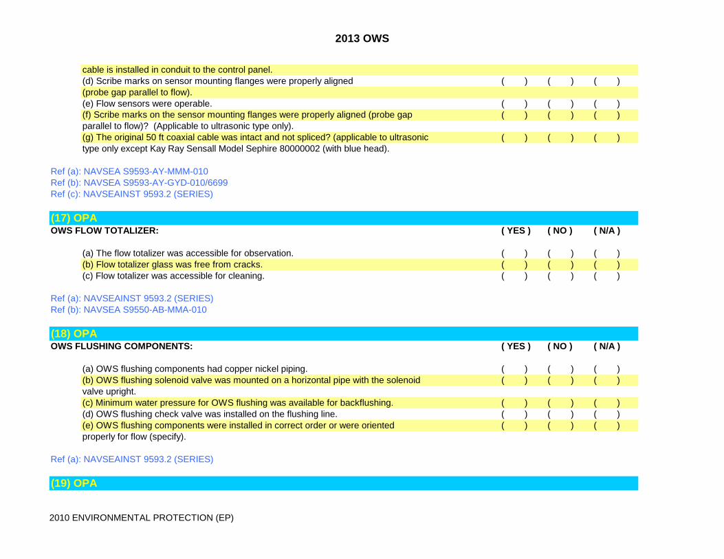
cable is installed in conduit to the control panel. (d) Scribe marks on sensor mounting flanges were properly aligned ( ) ( ) ( )(probe gap parallel to flow).(e) Flow sensors were operable. ( ) ( ) ( )(f) Scribe marks on the sensor mounting flanges were properly aligned (probe gap ( ) ( ) ( )parallel to flow)? (Applicable to ultrasonic type only). (g) The original 50 ft coaxial cable was intact and not spliced? (applicable to ultrasonic ( ) ( ) ( )type only except Kay Ray Sensall Model Sephire 80000002 (with blue head).
Ref (a): NAVSEA S9593-AY-MMM-010Ref (b): NAVSEA S9593-AY-GYD-010/6699Ref (c): NAVSEAINST 9593.2 (SERIES)
(17) OPA OWS FLOW TOTALIZER: ( YES ) ( NO ) ( N/A )
(a) The flow totalizer was accessible for observation. ( ) ( ) ( )(b) Flow totalizer glass was free from cracks. ( ) ( ) ( )(c) Flow totalizer was accessible for cleaning. ( ) ( ) ( )
Ref (a): NAVSEAINST 9593.2 (SERIES)Ref (b): NAVSEA S9550-AB-MMA-010
(18) OPA OWS FLUSHING COMPONENTS: ( YES ) ( NO ) ( N/A )
(a) OWS flushing components had copper nickel piping. ( ) ( ) ( )(b) OWS flushing solenoid valve was mounted on a horizontal pipe with the solenoid ( ) ( ) ( )valve upright.(c) Minimum water pressure for OWS flushing was available for backflushing. ( ) ( ) ( )(d) OWS flushing check valve was installed on the flushing line. ( ) ( ) ( )(e) OWS flushing components were installed in correct order or were oriented ( ) ( ) ( )properly for flow (specify).
Ref (a): NAVSEAINST 9593.2 (SERIES)
(19) OPA

2013 OWS
2010 ENVIRONMENTAL PROTECTION (EP)
OWS MEMBRANE FILTER UNIT: ( YES ) ( NO ) ( N/A )
(a) The membrane filter unit on the OWS was correctly installed. ( ) ( ) ( )(b) The membrane filter unit filters seated properly and denied any bypass flow. ( ) ( ) ( )(c) The membrane filter unit filters had been changed out. ( ) ( ) ( )(d) The membrane filter unit was operable. ( ) ( ) ( )(e) The “Backflush Failure” warning was operational. ( ) ( ) ( )(f) The “Bleed Failure” warning was operational. ( ) ( ) ( )(g) The “Clean Membranes” warning was operatoinal. ( ) ( ) ( )(h) The “Clean Strainer” warning was operational. ( ) ( ) ( )(i) The “Feed Pump Overload” alarm was operational. ( ) ( ) ( )(j) The “High loop temp” alarm was operational. ( ) ( ) ( )(k) The “Loop Blockage/Air Loss” alarm was operational. ( ) ( ) ( )(l) The “Loop Pressure Low” alarm was operational. ( ) ( ) ( )(m) The “Loop Pressure Overload” alarm was operational. ( ) ( ) ( )(n) The “Recirc Pump Overload” alarm was operational. ( ) ( ) ( )(o) The “Sensor Failure” alarm was operational. ( ) ( ) ( )(p) Potable water pressure at 30 psi (indicated by panel meters 2PI01 and 2PI02 with ( ) ( ) ( )the system in “OFF” and 3WV01 open) induced >4 gpm flow through flush valve 2FV01.(q) Bleed flow meter 2FM02 was operational. ( ) ( ) ( )(r) The bleed valve, 2BV01, operated manually. ( ) ( ) ( )(s) The flush valve, 2FV01, operated manually. ( ) ( ) ( )(t) The oil line discharge pressure was less than 25 psi during operation. ( ) ( ) ( )(u) The pump rotation was correct. ( ) ( ) ( )(v) All alarm lights operated when lamp test button was pushed. ( ) ( ) ( )(w) All pressure, temperature, and flow indicators on the meter panel were operational. ( ) ( ) ( )(x) All solenoid and motorized valves operated properly during system operation. ( ) ( ) ( )(y) All “mode” indicator lights on the control panel operated at the correct time. ( ) ( ) ( )(z) All vlv/motor indicator lights on the control panel operated at the correct time. ( ) ( ) ( )(aa) The permeate flow stabilized after about 15 minutes. ( ) ( ) ( )(bb) The recirculation loop temperature stabilized at about 80 deg F. ( ) ( ) ( )(cc) The system bled every 10 minutes? ( ) ( ) ( )(dd) The system went into backflush at the end of an operation. ( ) ( ) ( )(ee) The concentrate was dark and the was permeate nearly clear, indicates membrane integrity. ( ) ( ) ( )(ff) The pressure across the recirculation pump (2PI01-2PI02) was 30 to 40 psi. ( ) ( ) ( )(gg) The permeate discharge valve, 2PV01, operated manually. ( ) ( ) ( )(hh) The discharge pressure during operation was 5-25 psig while pumping overboard. ( ) ( ) ( )
2013 OWS
2010 ENVIRONMENTAL PROTECTION (EP)
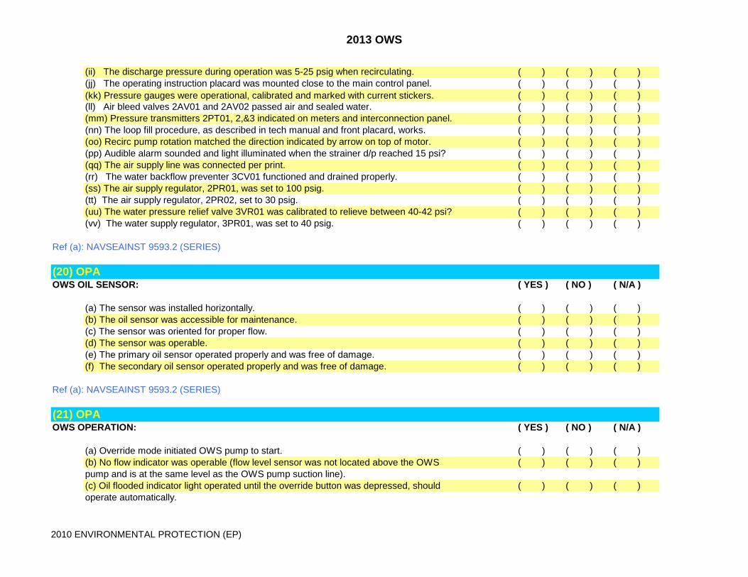
(ii) The discharge pressure during operation was 5-25 psig when recirculating. ( ) ( ) ( )(jj) The operating instruction placard was mounted close to the main control panel. ( ) ( ) ( )(kk) Pressure gauges were operational, calibrated and marked with current stickers. ( ) ( ) ( )(ll) Air bleed valves 2AV01 and 2AV02 passed air and sealed water. ( ) ( ) ( )(mm) Pressure transmitters 2PT01, 2,&3 indicated on meters and interconnection panel. ( ) ( ) ( )(nn) The loop fill procedure, as described in tech manual and front placard, works. ( ) ( ) ( )(oo) Recirc pump rotation matched the direction indicated by arrow on top of motor. ( ) ( ) ( )(pp) Audible alarm sounded and light illuminated when the strainer d/p reached 15 psi? ( ) ( ) ( )(qq) The air supply line was connected per print. ( ) ( ) ( )(rr) The water backflow preventer 3CV01 functioned and drained properly. ( ) ( ) ( )(ss) The air supply regulator, 2PR01, was set to 100 psig. ( ) ( ) ( )(tt) The air supply regulator, 2PR02, set to 30 psig. ( ) ( ) ( )(uu) The water pressure relief valve 3VR01 was calibrated to relieve between 40-42 psi? ( ) ( ) ( )(vv) The water supply regulator, 3PR01, was set to 40 psig. ( ) ( ) ( )
Ref (a): NAVSEAINST 9593.2 (SERIES)
(20) OPA OWS OIL SENSOR: ( YES ) ( NO ) ( N/A )
(a) The sensor was installed horizontally. ( ) ( ) ( )(b) The oil sensor was accessible for maintenance. ( ) ( ) ( )(c) The sensor was oriented for proper flow. ( ) ( ) ( )(d) The sensor was operable. ( ) ( ) ( )(e) The primary oil sensor operated properly and was free of damage. ( ) ( ) ( )(f) The secondary oil sensor operated properly and was free of damage. ( ) ( ) ( )
Ref (a): NAVSEAINST 9593.2 (SERIES)
(21) OPA OWS OPERATION: ( YES ) ( NO ) ( N/A )
(a) Override mode initiated OWS pump to start. ( ) ( ) ( )(b) No flow indicator was operable (flow level sensor was not located above the OWS ( ) ( ) ( )pump and is at the same level as the OWS pump suction line).(c) Oil flooded indicator light operated until the override button was depressed, should ( ) ( ) ( )operate automatically.
2013 OWS
2010 ENVIRONMENTAL PROTECTION (EP)
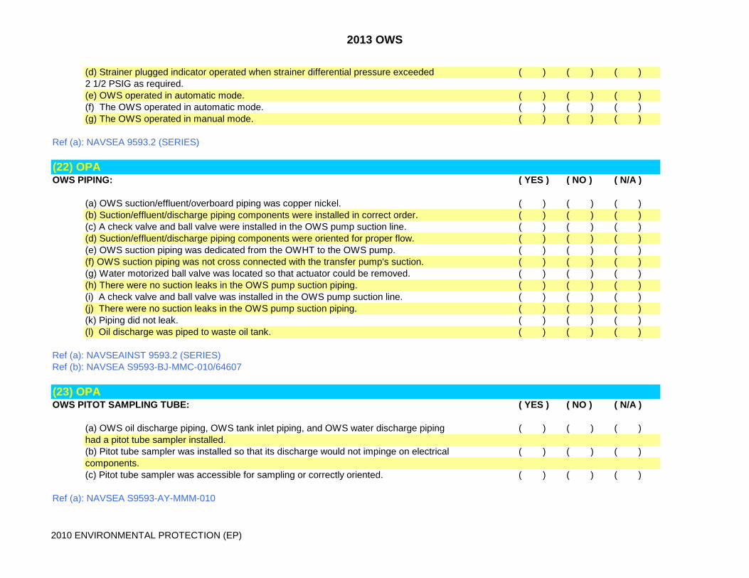
(d) Strainer plugged indicator operated when strainer differential pressure exceeded ( ) ( ) ( )2 1/2 PSIG as required.(e) OWS operated in automatic mode. ( ) ( ) ( )(f) The OWS operated in automatic mode. ( ) ( ) ( )(g) The OWS operated in manual mode. ( ) ( ) ( )
Ref (a): NAVSEA 9593.2 (SERIES)
(22) OPA OWS PIPING: ( YES ) ( NO ) ( N/A )
(a) OWS suction/effluent/overboard piping was copper nickel. ( ) ( ) ( )(b) Suction/effluent/discharge piping components were installed in correct order. ( ) ( ) ( )(c) A check valve and ball valve were installed in the OWS pump suction line. ( ) ( ) ( )(d) Suction/effluent/discharge piping components were oriented for proper flow. ( ) ( ) ( )(e) OWS suction piping was dedicated from the OWHT to the OWS pump. ( ) ( ) ( )(f) OWS suction piping was not cross connected with the transfer pump's suction. ( ) ( ) ( )(g) Water motorized ball valve was located so that actuator could be removed. ( ) ( ) ( )(h) There were no suction leaks in the OWS pump suction piping. ( ) ( ) ( )(i) A check valve and ball valve was installed in the OWS pump suction line. ( ) ( ) ( )(j) There were no suction leaks in the OWS pump suction piping. ( ) ( ) ( )(k) Piping did not leak. ( ) ( ) ( )(l) Oil discharge was piped to waste oil tank. ( ) ( ) ( )
Ref (a): NAVSEAINST 9593.2 (SERIES)Ref (b): NAVSEA S9593-BJ-MMC-010/64607
(23) OPA OWS PITOT SAMPLING TUBE: ( YES ) ( NO ) ( N/A )
(a) OWS oil discharge piping, OWS tank inlet piping, and OWS water discharge piping ( ) ( ) ( )had a pitot tube sampler installed. (b) Pitot tube sampler was installed so that its discharge would not impinge on electrical ( ) ( ) ( )components.(c) Pitot tube sampler was accessible for sampling or correctly oriented. ( ) ( ) ( )
Ref (a): NAVSEA S9593-AY-MMM-010
2013 OWS
2010 ENVIRONMENTAL PROTECTION (EP)
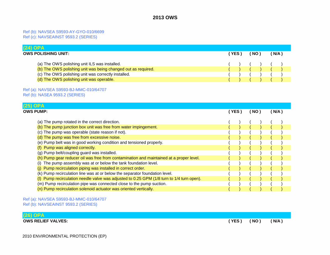
Ref (b): NAVSEA S9593-AY-GYO-010/6699Ref (c): NAVSEAINST 9593.2 (SERIES)
(24) OPA OWS POLISHING UNIT: ( YES ) ( NO ) ( N/A )
(a) The OWS polishing unit ILS was installed. ( ) ( ) ( )(b) The OWS polishing unit was being changed out as required. ( ) ( ) ( )(c) The OWS polishing unit was correctly installed. ( ) ( ) ( )(d) The OWS polishing unit was operable. ( ) ( ) ( )
Ref (a): NAVSEA S9593-BJ-MMC-010/64707Ref (b): NASEA 9593.2 (SERIES)
(25) OPA OWS PUMP: ( YES ) ( NO ) ( N/A )
(a) The pump rotated in the correct direction. ( ) ( ) ( )(b) The pump junction box unit was free from water impingement. ( ) ( ) ( )(c) The pump was operable (state reason if not). ( ) ( ) ( )(d) The pump was free from excessive noise. ( ) ( ) ( )(e) Pump belt was in good working condition and tensioned properly. ( ) ( ) ( )(f) Pump was aligned correctly. ( ) ( ) ( )(g) Pump belt/coupling guard was installed. ( ) ( ) ( )(h) Pump gear reducer oil was free from contamination and maintained at a proper level. ( ) ( ) ( )(i) The pump assembly was at or below the tank foundation level. ( ) ( ) ( )(j) Pump recirculation piping was installed in correct order. ( ) ( ) ( )(k) Pump recirculation line was at or below the separator foundation level. ( ) ( ) ( )(l) Pump recirculation needle valve was adjusted to 0.25 GPM (1/8 turn to 1/4 turn open). ( ) ( ) ( )(m) Pump recirculation pipe was connected close to the pump suction. ( ) ( ) ( )(n) Pump recirculation solenoid actuator was oriented vertically. ( ) ( ) ( )
Ref (a): NAVSEA S9593-BJ-MMC-010/64707Ref (b): NAVSEAINST 9593.2 (SERIES)
(26) OPA OWS RELIEF VALVES: ( YES ) ( NO ) ( N/A )

2013 OWS
2010 ENVIRONMENTAL PROTECTION (EP)
(a) The OPB-10NP relief valve discharge was piped to the bilge. ( ) ( ) ( )(b) The OPB-10NP relief valve test setting label was present. ( ) ( ) ( )(c) The OPB-10NP relief valve relieved at 28 PSI as determined by closing V3 when ( ) ( ) ( )the system was operating.
Ref (a): NAVSEA S9593-AY-MMM-010 Ref (b): NAVSEA S9593-AY-GYD-010/6699Ref (c): NAVSEAINST 9593.2 (SERIES)
(27) OPA OWS SENSORS: ( YES ) ( NO ) ( N/A )
(a) Primary/back-up oil/water sensor stuffing tubes were in place around cable penetrations. ( ) ( ) ( )(b) Primary/back-up oil sensor had sufficient clearance to be removed from tank ( ) ( ) ( )without disassembly.(c) Primary back-up oil sensors were operable. ( ) ( ) ( )(d) Primary back-up oil sensors were adjusted correctly (capacitance type). ( ) ( ) ( )
Ref (a): NAVSEAINST 9593.2 (SERIES)Ref (b): NAVSEA S9550-AB-MMA-010
(28) OPA OWS SIGHT GLASS: ( YES ) ( NO ) ( N/A )
(a) The sight glass was installed with the sight glass oriented for a horizontal line of sight, ( ) ( ) ( )and accessible for backlighting and observation. (b) The sight glass was not dirty/damaged. ( ) ( ) ( )
Ref (a): NAVSEA S9593-AY-MMM-010Ref (b): NAVSEA S9593-AY-GYD-010/6699Ref (c): NAVSEAINST 9593.2 (SERIES)
(29) OPA OWS STRAINER: ( YES ) ( NO ) ( N/A )
(a) The duplex basket strainer was mounted with yoke flush or above the deck plate and was ( ) ( ) ( )

2013 OWS
2010 ENVIRONMENTAL PROTECTION (EP)
accessible for operation. (b) The differential pressure switch was mounted near the strainer and is operable. ( ) ( ) ( )(c) Strainer basket was installed. ( ) ( ) ( )(d) Gaskets were present in strainer and in good condition. ( ) ( ) ( )(e) Strainer installed correctly. ( ) ( ) ( )(f) Strainer basket was free from clogs and debris. ( ) ( ) ( )(g) D/P switch gage lines were installed correctly. ( ) ( ) ( )
Ref (a): NAVSEA S9593-AY-MMM-010Ref (b): NAVSEA S9593-AY-GYD-010/6699Ref (c): NAVSEAINST 9593.2 (SERIES)
(30) OPA OWS SYSTEM GAGES: ( YES ) ( NO ) ( N/A )
(a) Gages had current calibration/NCR labels. ( ) ( ) ( )(b) Gages were operable. ( ) ( ) ( )(c) Gages were correctly installed. ( ) ( ) ( )(e) The gages were visible from the control panel. ( ) ( ) ( )(f) The gage lines were installed to meet the flexibility requirement. ( ) ( ) ( )(g) The gage lines were protected from inadvertent damage. ( ) ( ) ( )(h) The gage line isolation valve 1/4" globe-type union end was equipped for both water and oil service. ( ) ( ) ( )(i) The gage was in good condition and had a current calibration/NCR labels. ( ) ( ) ( )(j) Gage lines were free from leaks and clogs. ( ) ( ) ( )
Ref (a): NAVSEAINST 9593.2 (SERIES)Ref (b): NAVSEA S9593-CD-MMO-010/25204Ref (c): NAVSEA S9593-AY-MMM-010Ref (d): NAVSEA S9593-AY-GYD-010/6699
(31) OPA OWS TANK: ( YES ) ( NO ) ( N/A )
(a) The (specify model) OWS had 16 inches of end clearance to remove the plates for ( ) ( ) ( )maintenance and or inspection. (b) The OWS drain was piped to the bilge or OWHT with a funnel. ( ) ( ) ( )(c) There was a three foot clearance above the OWS cover. ( ) ( ) ( )

2013 OWS
2010 ENVIRONMENTAL PROTECTION (EP)
(d) The OWS foundation influent ends 3-5 inches higher than the effluent end. ( ) ( ) ( )(e) OWS tank priming piping was copper nickel. ( ) ( ) ( )(f) OWS tank priming system components were installed in the correct order and ( ) ( ) ( )oriented for proper flow. (g) Hard piped source of water was available for OWS tank priming (sea water or potable). ( ) ( ) ( )(h) The air vent was installed horizontally with the cap oriented down. ( ) ( ) ( )(i) All vent pipes pointed down to prevent a spray hazard to personnel. ( ) ( ) ( )(j) Air vent was operable (prevented flow of water out of OWS tank). ( ) ( ) ( )(k) Machalt 315 was installed, replacing the BIRCO air vent with a SARCO air vent. ( ) ( ) ( )(l) The water vent and isolation valve was installed on the oil tower below the air vent line. ( ) ( ) ( )
Ref (a): NAVSEAINST 9593.2 (SERIES)Ref (b): NAVSEA S9550-BD-MMO-010
(32) OPA OWT PIPING: ( YES ) ( NO ) ( N/A )
(a) There were means provided for pumping the aft steering bilge areas. OWT system ( ) ( ) ( )extends to all spaces capable of generating oily waste. (b) There were means provided for pumping bilge areas (space noun name). OWT system ( ) ( ) ( )extended to all spaces capable of generating oily waste. (c) An expanded corrosion resistant metal screen (MONEL, ST, ETC) was installed ( ) ( ) ( )around bilge suction terminals. (d) A check valve and ball valve was installed on (specify) suction. ( ) ( ) ( )(e) Hose connections were provided to service all areas not accessible with dedicated piping. ( ) ( ) ( )
Ref (a): OPNAVINST 5090.1 (SERIES)Ref (b): NAVSEAINST 9593.2 (SERIES)Ref (c): ECP-51-1344 (DDG 51)
(33) OPA OWT PUMP: ( YES ) ( NO ) ( N/A )
(a) Pump was operable. ( ) ( ) ( )(b) Blackmer pump was provided with recirc chamber. ( ) ( ) ( )(c) The OWT/FO stripping pumps were cross-connected on the suction side by a ball ( ) ( ) ( )valve and isolation check valve.

2013 OWS
2010 ENVIRONMENTAL PROTECTION (EP)
(d) The OWT/FO stripping pump discharge pipes were cross connected with a licked closed ( ) ( ) ( )isolation valve. (e) One motor driven pump was installed and used for OWT (applies to steam ships with ( ) ( ) ( )reciprocating pumps).(f) OWT pump was properly sized to off-load OWHT in 1 to 2 hours. ( ) ( ) ( )(g) Inlet connection for the recirculation chamber was at the same level as the OWT pump. ( ) ( ) ( )(h) The outlet connection for the recirculation chamber was higher than the inlet connection. ( ) ( ) ( )(i) All strainers were in good material condition. ( ) ( ) ( )(j) All strainers have installed gaskets. ( ) ( ) ( )
Ref (a): NAVSEA 9593.2 (SERIES)Ref (b): OPNAVINST 5090.1 (SERIES)
(34) OPA OWT SYSTEM GAGES: ( YES ) ( NO ) ( N/A )
(a) OWT gages had current calibration/NCR labels. ( ) ( ) ( )(b) OWT gages were operable. ( ) ( ) ( )(c) OWT gages were correctly installed. ( ) ( ) ( )(d) The gages were visible from the control panel. ( ) ( ) ( )(e) The gage lines were installed to meet the flexibility requirement. ( ) ( ) ( )(f) The gage lines were protected from inadvertent damage. ( ) ( ) ( )(g) The gage line isolation valve 1/4" globe-type union end was equipped for both ( ) ( ) ( )water and oil service. (h) Gage lines did were free from leaks and clogs. ( ) ( ) ( )
Ref (a): NAVSEAINST 9593.2 (SERIES)Ref (b): NSTM 593
(35) OPA OWT SYSTEM GAGES: ( YES ) ( NO ) ( N/A )
(a) Valves were labeled. ( ) ( ) ( )(b) All handles were in good working order. ( ) ( ) ( )(c) Valves were operable. ( ) ( ) ( )(d) Valves were free of leaks. ( ) ( ) ( )(e) Valves were color coded black. ( ) ( ) ( )

2013 OWS
2010 ENVIRONMENTAL PROTECTION (EP)
Ref (a): NAVSEA 9593.2 (SERIES)
(35) OPA PLACARD, DISCHARGE PROHIBITION: ( YES ) ( NO ) ( N/A )
(a) Oil pollution abatement signs were conspicuously posted at the following locations: ( ) ( ) ( ) - Shore connection deck risers. ( ) ( ) ( ) - Pump controllers (local and remote). ( ) ( ) ( ) - Overboard discharge valves. ( ) ( ) ( ) - OWS controllers. ( ) ( ) ( ) - FAS stations. ( ) ( ) ( )(LIST OTHERS AS NEEDED). ( ) ( ) ( )(b) These signs must state ( ) ( ) ( ) "WARNING"Overboard discharge of oily waste or waste oil is prohibited. Oily wastewater discharge shall be limited to15 PPM oil-in-water worldwide.All US naval vessels equipped with an Oil Pollution Abatement System shall utilize the system to process oily wastewater prior to overboard discharge. Within 12 nautical miles of the U.S. coastline, no oil or oily wastewater that will cause a sheen or surfacefilm on the water or discoloration beneath the surface of the water shall be permitted. Within this zone, nooily wastewater that exceeds 15 PPM oil-in-water shall be discharged. Any unacceptable discharges shall be reported immediately in accordance with OPNAVINST 5090.1C.U.S. naval vessals shall refrain from discharging oil or oily waste in MARPOL Annex I special areas to theextent practicable without endangering the ship or impairing its operation or operational effectiveness.Discharges that are necessary in MARPOL Annex I special areas or elsewhere on the high seas shall be limited to 15 PPM. Operational guidance is provided in OPNAVINST 5090.1C.Within 12 nautical miles of foreign countries and for other special requirements, U.S. naval vessels shall abide by regulations specified in the Status of Forces Agreement (SOFA), OPNAVINST 5090.1C, and DOD Regulations 4715.6-R1.
Ref (a): 33 CFR 155.450 (PLACARD)Ref (b): NSTM 593Ref (c): OPNAVINST 5090.1 (SERIES)Ref (d): NAVSEAINST 9593.2 (SERIES)
(36) OPA
2013 OWS
2010 ENVIRONMENTAL PROTECTION (EP)
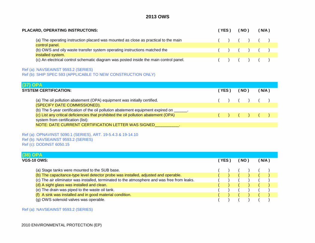
PLACARD, OPERATING INSTRUCTONS: ( YES ) ( NO ) ( N/A )
(a) The operating instruction placard was mounted as close as practical to the main ( ) ( ) ( )control panel. (b) OWS and oily waste transfer system operating instructions matched the ( ) ( ) ( )installed system. (c) An electrical control schematic diagram was posted inside the main control panel. ( ) ( ) ( )
Ref (a): NAVSEAINST 9593.2 (SERIES)Ref (b): SHIP SPEC 593 (APPLICABLE TO NEW CONSTRUCTION ONLY)
(37) OPA SYSTEM CERTIFICATION: ( YES ) ( NO ) ( N/A )
(a) The oil pollution abatement (OPA) equipment was initially certified. ( ) ( ) ( )(SPECIFY DATE COMMISSIONED).(b) The 5-year certification of the oil pollution abatement equipment expired on ______.(c) List any critical deficiencies that prohibited the oil pollution abatement (OPA) ( ) ( ) ( )system from certification (list):NOTE: DATE CURRENT CERTIFICATION LETTER WAS SIGNED___________.
Ref (a): OPNAVINST 5090.1 (SERIES), ART. 19-5.4.3 & 19-14.10Ref (b): NAVSEAINST 9593.2 (SERIES)Ref (c): DODINST 6050.15
(38) OPA VGS-10 OWS: ( YES ) ( NO ) ( N/A )
(a) Stage tanks were mounted to the SUB base. ( ) ( ) ( )(b) The capacitance-type level detector probe was installed, adjusted and operable. ( ) ( ) ( )(c) The air eliminator was installed, terminated to the atmosphere and was free from leaks. ( ) ( ) ( )(d) A sight glass was installed and clean. ( ) ( ) ( )(e) The drain was piped to the waste oil tank. ( ) ( ) ( )(f) A sink was installed and in good material condition. ( ) ( ) ( )(g) OWS solenoid valves was operable. ( ) ( ) ( )
Ref (a): NAVSEAINST 9593.2 (SERIES)

2013 OWS
2010 ENVIRONMENTAL PROTECTION (EP)
Ref (b): S9550-AN-MMO-010/MOD VGS-10Ref (c): S9550-BE-MMA-010/53918
(39) OPA WOT TANK LEVEL INDICATORS: ( YES ) ( NO ) ( N/A )
(a) The WOT tank level indicators were operable. ( ) ( ) ( )(b) The WOT tank level indicators were correctly installed. ( ) ( ) ( )
Ref (a): NAVSEAINST 9593.2 (SERIES)

2013 CHT
2010 ENVIRONMENTAL PROTECTION (EP)
ENVIRONMENTAL PROTECTION INSURV CHECKLIST FOR INSPECTION PREPARATION AND SELF EVALUATION
(1) CHT COMMINUTOR: ( YES ) ( NO ) ( N/A )
(a) Comminutor installed/running properly. ( ) ( ) ( )(b) Comminutor operational. ( ) ( ) ( )(c) Comminutor have the required maintenance access. ( ) ( ) ( )(d) Belt safety guard installed correctly with all fasteners. ( ) ( ) ( )(e) Comminutor was free of effluent leaks. ( ) ( ) ( )(f) Comminuter rotating in the proper direction. ( ) ( ) ( )(g) All fasteners were non-ferrous. ( ) ( ) ( )
Ref (a): NSTM 593Ref (b): SHIP SPEC 593 (DDG-51 AND LHD-2 AT/FCT'S ONLY)Ref (b): NAVSEAINST 9593.1 (SERIES)
(2) CHTCHT DECK RISERS: ( YES ) ( NO ) ( N/A )
(a) All sewage deck risers and valves had the required label plates and plaquards. ( ) ( ) ( )(b) The sewage overboard deck riser has an air blow-out fitting installed. ( ) ( ) ( )(c) The sewage overboard deck riser was properly oriented for shore hose hookup. ( ) ( ) ( )(d) The deck riser station was fitted with a camlock or similar fitting. ( ) ( ) ( )(e) The sewage deck riser was fitted with a camlock cap and/or keeper chain. ( ) ( ) ( )(f) The padeye was available near the sewage discharge deck riser to assist in hauling-up ( ) ( ) ( )and lashing the sewage hoses in place.(g) L/P air station was avaible and operational at each station. ( ) ( ) ( )(h) An L/P air hose assembly was available to conduct blowdowns. ( ) ( ) ( )(i) All stations had an oversized drip pan to place under discharge hose connetion. ( ) ( ) ( )(j) All fasteners were non-ferrous. ( ) ( ) ( )
2013 CHT
2010 ENVIRONMENTAL PROTECTION (EP)
Ref (b): NAVSEAINST 9593.1 (SERIES)Ref (b): NSTM 593
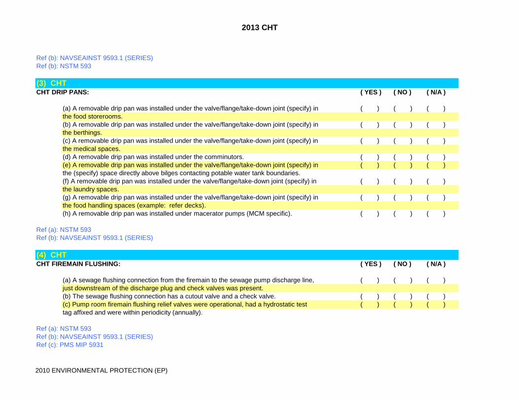
(3) CHTCHT DRIP PANS: ( YES ) ( NO ) ( N/A )
(a) A removable drip pan was installed under the valve/flange/take-down joint (specify) in ( ) ( ) ( )the food storerooms.(b) A removable drip pan was installed under the valve/flange/take-down joint (specify) in ( ) ( ) ( )the berthings.(c) A removable drip pan was installed under the valve/flange/take-down joint (specify) in ( ) ( ) ( )the medical spaces.(d) A removable drip pan was installed under the comminutors. ( ) ( ) ( )(e) A removable drip pan was installed under the valve/flange/take-down joint (specify) in ( ) ( ) ( )the (specify) space directly above bilges contacting potable water tank boundaries.(f) A removable drip pan was installed under the valve/flange/take-down joint (specify) in ( ) ( ) ( )the laundry spaces.(g) A removable drip pan was installed under the valve/flange/take-down joint (specify) in ( ) ( ) ( )the food handling spaces (example: refer decks).(h) A removable drip pan was installed under macerator pumps (MCM specific). ( ) ( ) ( )
Ref (a): NSTM 593Ref (b): NAVSEAINST 9593.1 (SERIES)
(4) CHTCHT FIREMAIN FLUSHING: ( YES ) ( NO ) ( N/A )
(a) A sewage flushing connection from the firemain to the sewage pump discharge line, ( ) ( ) ( )just downstream of the discharge plug and check valves was present.(b) The sewage flushing connection has a cutout valve and a check valve. ( ) ( ) ( )(c) Pump room firemain flushing relief valves were operational, had a hydrostatic test ( ) ( ) ( )tag affixed and were within periodicity (annually).
Ref (a): NSTM 593Ref (b): NAVSEAINST 9593.1 (SERIES)Ref (c): PMS MIP 5931

2013 CHT
2010 ENVIRONMENTAL PROTECTION (EP)
(5) CHTCHT FLOODING ALARMS IN SUMPS/COAMINGS: ( YES ) ( NO ) ( N/A )
(a) Required flooding detector was present in the sewage holding tank space/coaming (Specify). ( ) ( ) ( )(b) CHT/VCHT flooding alarm was operable. ( ) ( ) ( )(c) CHT/VCHT flooding alarm actuated in CCS/DC Central (Specify). ( ) ( ) ( )(d) CHT/VCHT sump/coaming eductor was operational. ( ) ( ) ( )(e) VCHT sump/coaming and deep sink could be evacuated back to the VCHT tank. ( ) ( ) ( )(e) CHT/VCHT sump/coaming eductor gauges and valves were operational. ( ) ( ) ( )(f) CHT/VCHT sump/coaming were water tight. ( ) ( ) ( )(g) CHT/VCHT sumps had debris screens installed over the opening. ( ) ( ) ( )
Ref (a): NSTM 593Ref (b): NAVSEAINST 9593.1 (SERIES)Ref (c): SHIP SPEC 436 (DDG-51 AND LHD-2 AT/FCT'S ONLY)Ref (D): PMS MIP 5931
(6) CHTCHT GAGES: ( YES ) ( NO ) ( N/A )
(a) Gages have a current calibration/NCR sticker. ( ) ( ) ( )(b) Gage redline was set. ( ) ( ) ( )(c) Gages were operable. ( ) ( ) ( )(d) Sewage pump suction and discharge gage has diaphragm seals or ring isolators were ( ) ( ) ( )installed to preclude clogging of the gage and gage lines by sewage solids.
Ref (a): NSTM 593Ref (b): NAVSEAINST 9593.1 (SERIES)
(7) CHTCHT HYDROGEN SULFIDE (H2S) ALARM: ( YES ) ( NO ) ( N/A )
(a) H2S alarms were installed ( ) ( ) ( )(b) H2S alarms were operable. ( ) ( ) ( )(c) H2S alarm detector head display lights were not illuminated on H2S remote panel. ( ) ( ) ( )(d) H2S alarm 10 ppm detectors passed calibration gas testing. ( ) ( ) ( )

2013 CHT
2010 ENVIRONMENTAL PROTECTION (EP)
(e) H2S alarm panel self test/50 ppm test was satisfactory. ( ) ( ) ( )(f) H2S alarms activated in local and remote stations. ( ) ( ) ( )(g) H2S alarm condition warning (10ppm) /danger (50ppm) audible alarms were operable. ( ) ( ) ( )(h) H2S alarm condition warning (yellow) /danger (red) visual beacons were operable. ( ) ( ) ( )(i) H2S calibration gas/associated test fittings were available and cal gas was not expired. ( ) ( ) ( )(j) H2S calibration testing logs were maintained IAW PMS. ( ) ( ) ( )
Ref (a): NSTM 593Ref (b): NAVSEAINST 9593.1 (SERIES)Ref (c): MIP 4361/015SHIP SPECIFIC SHIPALTS:CV-7904K CVN-7905K LCC-1126K LKA-1229K LPD-992K AGF-992K LPH-1101KLSD-36-439K LSD-41-1072K AD-2010K AE-1363K AFS-619K AO-20963K AOE-664K AS-2356KAS-2356K ARS-38-513K AOR-670K AE-1362K ARS-50-1062K
(8) CHTCHT/VCHT PUMP ROOM VENTILATION SHUTDOWN AIRFLOW ALARMS: ( YES ) ( NO ) ( N/A )
(a) Pump room supply and exhaust ventilation was operational. ( ) ( ) ( )(b) Local audible and visual alarms activated when ventilation was secured. ( ) ( ) ( )(c) Local alarm acknowledge function operated and only secured the audible alarm. ( ) ( ) ( )(d) Remote audible and visual alarms activate when ventilation was secured. ( ) ( ) ( )(e) Local and remote alarms cleared within six minutes of restoring ventilation. ( ) ( ) ( )
Ref (a): NSTM 593Ref (b): NAVSEAINST 9593.1 (SERIES)Ref (c): MIP 5931
(9) CHTCHT ILS DOCUMENTATION: ( YES ) ( NO ) ( N/A )
(a) System drawing was available/accurate. ( ) ( ) ( )(b) Equipment technical manuals (Specify) were available / updated. ( ) ( ) ( )(c) DC diagrams reflected system accurately. ( ) ( ) ( )(d) PMS was installed. ( ) ( ) ( )(e) SDOSS was accurate. ( ) ( ) ( )(f) APL's were onboard/ accurate. ( ) ( ) ( )
2013 CHT
2010 ENVIRONMENTAL PROTECTION (EP)
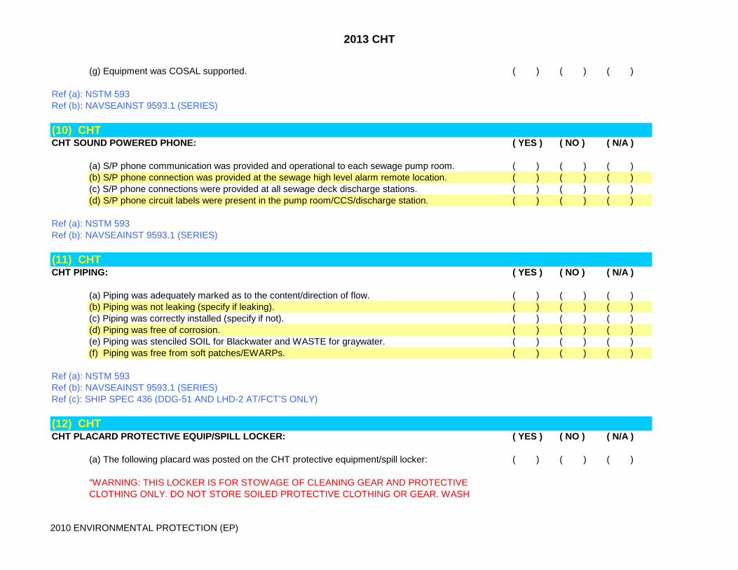
(g) Equipment was COSAL supported. ( ) ( ) ( )
Ref (a): NSTM 593Ref (b): NAVSEAINST 9593.1 (SERIES)
(10) CHTCHT SOUND POWERED PHONE: ( YES ) ( NO ) ( N/A )
(a) S/P phone communication was provided and operational to each sewage pump room. ( ) ( ) ( )(b) S/P phone connection was provided at the sewage high level alarm remote location. ( ) ( ) ( )(c) S/P phone connections were provided at all sewage deck discharge stations. ( ) ( ) ( )(d) S/P phone circuit labels were present in the pump room/CCS/discharge station. ( ) ( ) ( )
Ref (a): NSTM 593Ref (b): NAVSEAINST 9593.1 (SERIES)
(11) CHTCHT PIPING: ( YES ) ( NO ) ( N/A )
(a) Piping was adequately marked as to the content/direction of flow. ( ) ( ) ( )(b) Piping was not leaking (specify if leaking). ( ) ( ) ( )(c) Piping was correctly installed (specify if not). ( ) ( ) ( )(d) Piping was free of corrosion. ( ) ( ) ( )(e) Piping was stenciled SOIL for Blackwater and WASTE for graywater. ( ) ( ) ( )(f) Piping was free from soft patches/EWARPs. ( ) ( ) ( )
Ref (a): NSTM 593Ref (b): NAVSEAINST 9593.1 (SERIES)Ref (c): SHIP SPEC 436 (DDG-51 AND LHD-2 AT/FCT'S ONLY)
(12) CHTCHT PLACARD PROTECTIVE EQUIP/SPILL LOCKER: ( YES ) ( NO ) ( N/A )
(a) The following placard was posted on the CHT protective equipment/spill locker: ( ) ( ) ( )
"WARNING: THIS LOCKER IS FOR STOWAGE OF CLEANING GEAR AND PROTECTIVE CLOTHING ONLY. DO NOT STORE SOILED PROTECTIVE CLOTHING OR GEAR. WASH

2013 CHT
2010 ENVIRONMENTAL PROTECTION (EP)
CLEANING GEAR (SWABS, BUCKETS, ETC) THOROUGHLY BEFORE RETURNING TO LOCKER."
Ref (a): NSTM 593Ref (b): NAVSEAINST 9593.1 (SERIES)Ref (c): NSTM 671
(13) CHTCHT PLACARD, AIRFLOW ALARM: ( YES ) ( NO ) ( N/A )
(a) The following placard was conspicuously posted on the exterior of the access door to ( ) ( ) ( )the sewage space:
"WARNING - ALARM INDICATES LOW AIR FLOW IN VENTILATION SYSTEM SERVING THIS COMPARTMENT. TAKE IMMEDIATE ACTION TO RESTORE VENTILATION. DO NOT ENTER WITHOUT RESPIRATORYPROTECTION OR UNTIL COMPARTMENT VENTILATION HAS BEEN
RESTORED FOR AT LEAST 15 MINUTES. EVACUATE THE COMPARTMENT IMMEDIATELY"UPON SOUNDING OF ALARM."
Ref (a): NAVSEA T9500-AA-PRO-100, PARA 3.1.84Ref (b): NAVSEAINST 9593.1 (SERIES)Ref (c): GSO 437
(14) CHTCHT PLACARD, CONNECTION STATION: ( YES ) ( NO ) ( N/A )
(a) The following placard(s) was/were posted at the deck riser connection station. A transfer ( ) ( ) ( )operating instruction placard and/or a sanitary health precaution placard (Delete if itdoes not apply).
CAUTION
DO NOT DISCONNECT SEWAGE HOSE WHILE IT IS PRESSURIZED.DEPRESSURIZE HOSE AND SECURE DISCHARGE CUT-OFF VALVE PRIORTO DISCONNECTING HOSE.
HOSE HOOK-UP PROCEDURES
2013 CHT
2010 ENVIRONMENTAL PROTECTION (EP)
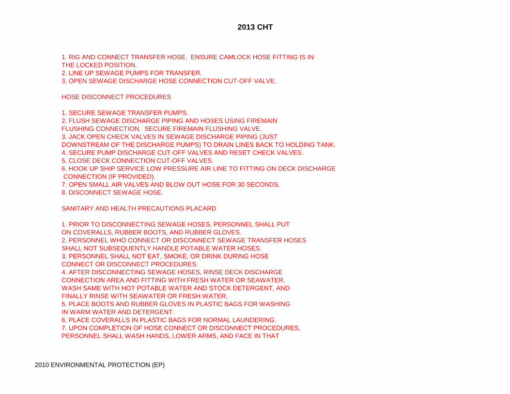
1. RIG AND CONNECT TRANSFER HOSE. ENSURE CAMLOCK HOSE FITTING IS INTHE LOCKED POSITION.2. LINE UP SEWAGE PUMPS FOR TRANSFER.3. OPEN SEWAGE DISCHARGE HOSE CONNECTION CUT-OFF VALVE.
HOSE DISCONNECT PROCEDURES
1. SECURE SEWAGE TRANSFER PUMPS.2. FLUSH SEWAGE DISCHARGE PIPING AND HOSES USING FIREMAINFLUSHING CONNECTION. SECURE FIREMAIN FLUSHING VALVE.3. JACK OPEN CHECK VALVES IN SEWAGE DISCHARGE PIPING (JUSTDOWNSTREAM OF THE DISCHARGE PUMPS) TO DRAIN LINES BACK TO HOLDING TANK.4. SECURE PUMP DISCHARGE CUT-OFF VALVES AND RESET CHECK VALVES.5. CLOSE DECK CONNECTION CUT-OFF VALVES.6. HOOK UP SHIP SERVICE LOW PRESSURE AIR LINE TO FITTING ON DECK DISCHARGE CONNECTION (IF PROVIDED).7. OPEN SMALL AIR VALVES AND BLOW OUT HOSE FOR 30 SECONDS.8. DISCONNECT SEWAGE HOSE.
SANITARY AND HEALTH PRECAUTIONS PLACARD
1. PRIOR TO DISCONNECTING SEWAGE HOSES, PERSONNEL SHALL PUTON COVERALLS, RUBBER BOOTS, AND RUBBER GLOVES.2. PERSONNEL WHO CONNECT OR DISCONNECT SEWAGE TRANSFER HOSESSHALL NOT SUBSEQUENTLY HANDLE POTABLE WATER HOSES.3. PERSONNEL SHALL NOT EAT, SMOKE, OR DRINK DURING HOSECONNECT OR DISCONNECT PROCEDURES.4. AFTER DISCONNECTING SEWAGE HOSES, RINSE DECK DISCHARGECONNECTION AREA AND FITTING WITH FRESH WATER OR SEAWATER,WASH SAME WITH HOT POTABLE WATER AND STOCK DETERGENT, ANDFINALLY RINSE WITH SEAWATER OR FRESH WATER.5. PLACE BOOTS AND RUBBER GLOVES IN PLASTIC BAGS FOR WASHINGIN WARM WATER AND DETERGENT.6. PLACE COVERALLS IN PLASTIC BAGS FOR NORMAL LAUNDERING.7. UPON COMPLETION OF HOSE CONNECT OR DISCONNECT PROCEDURES,PERSONNEL SHALL WASH HANDS, LOWER ARMS, AND FACE IN THAT
2013 CHT
2010 ENVIRONMENTAL PROTECTION (EP)
ORDER WITH HOT POTABLE WATER AND SOAP.
Ref (a): OPNAVINST 5090.1 (SERIES)Ref (b): NAVSEAINST 9593.1 (SERIES)Ref (c): NSTM 593
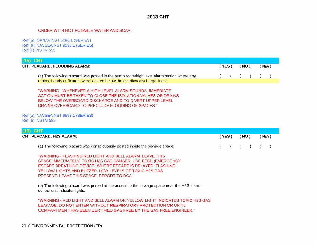
(15) CHTCHT PLACARD, FLOODING ALARM: ( YES ) ( NO ) ( N/A )
(a) The following placard was posted in the pump room/high level alarm station where any ( ) ( ) ( )drains, heads or fixtures were located below the overflow discharge lines:
"WARNING - WHENEVER A HIGH LEVEL ALARM SOUNDS, IMMEDIATEACTION MUST BE TAKEN TO CLOSE THE ISOLATION VALVES OR DRAINSBELOW THE OVERBOARD DISCHARGE AND TO DIVERT UPPER LEVELDRAINS OVERBOARD TO PRECLUDE FLOODING OF SPACES."
Ref (a): NAVSEAINST 9593.1 (SERIES)Ref (b): NSTM 593
(16) CHTCHT PLACARD, H2S ALARM: ( YES ) ( NO ) ( N/A )
(a) The following placard was conspicuously posted inside the sewage space: ( ) ( ) ( )
"WARNING - FLASHING RED LIGHT AND BELL ALARM. LEAVE THISSPACE IMMEDIATELY. TOXIC H2S GAS DANGER. USE EEBD (EMERGENCYESCAPE BREATHING DEVICE) WHERE ESCAPE IS DELAYED. FLASHINGYELLOW LIGHTS AND BUZZER. LOW LEVELS OF TOXIC H2S GASPRESENT. LEAVE THIS SPACE. REPORT TO DCA."
(b) The following placard was posted at the access to the sewage space near the H2S alarmcontrol unit indicator lights:
"WARNING - RED LIGHT AND BELL ALARM OR YELLOW LIGHT INDICATES TOXIC H2S GASLEAKAGE. DO NOT ENTER WITHOUT RESPIRATORY PROTECTION OR UNTIL COMPARTMENT HAS BEEN CERTIFIED GAS FREE BY THE GAS FREE ENGINEER."

2013 CHT
2010 ENVIRONMENTAL PROTECTION (EP)
Ref (a): NAVSEA T9500-AA-PRO-100, PARA 3.1.84Ref (b): NAVSEAINST 9593.1 (SERIES)Ref (c): GSO 437
(17) CHTCHT PLACARD, PUMP ROOM ACCESS: ( YES ) ( NO ) ( N/A )
(a) The following placard was posted at the sewage space access: ( ) ( ) ( )
WARNING1. SEWAGE SPILLS CAN PRODUCE HAZARDOUS GASES.2. USE EEBD MOUNTED IN PUMP ROOM FOR EMERGENCY ESCAPE INEVENT OF SEWAGE SPILL.3. FOLLOW SAFETY PROCEDURES IN NAVAL SHIPS TECHNICAL MANUAL,ENTITLED “POLLUTION CONTROL,” PUBLICATION NAVSEAS9086–T8–STM-010/CH-593 DURING MAINTENANCE OR CLEAN UP.4. USE SAR/SCBA ONLY FOR EMERGENCY RESCUE AND DAMAGE CONTROL(SECURING OF FLOODING).
Ref (a): NAVSEAINST 9593.1 (SERIES)Ref (b): NSTM 593
(18) CHTCHT PLACARD, SEWAGE SPACE HEALTH/SANITATION WARNING: ( YES ) ( NO ) ( N/A )
(a) The following health warning placard was conspicuously posted in the sewage ( ) ( ) ( )pump/ comminuter room:
WARNING
HEALTH AND SANITARY PRECAUTIONS TO BE OBSERVED PRIOR TO, DURING, AND AFTER SEWAGE PLANT MAINTENANCE:1. PRIOR TO WORKING ON THE SEWAGE PLANT OR CLEANING A SPILL,PERSONNEL SHALL: (A) OBTAIN STOCK DETERGENT, BUCKETS, MOP AND PLASTICLAUNDRY SIZED BAGS. THESE SHOULD BE PLACED IN THE
2013 CHT
2010 ENVIRONMENTAL PROTECTION (EP)
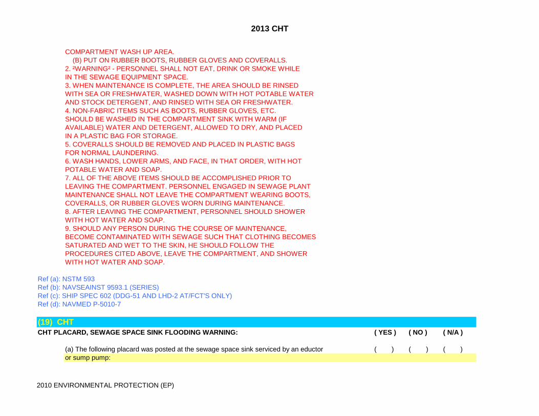
COMPARTMENT WASH UP AREA. (B) PUT ON RUBBER BOOTS, RUBBER GLOVES AND COVERALLS.2. ²WARNING² - PERSONNEL SHALL NOT EAT, DRINK OR SMOKE WHILEIN THE SEWAGE EQUIPMENT SPACE.3. WHEN MAINTENANCE IS COMPLETE, THE AREA SHOULD BE RINSEDWITH SEA OR FRESHWATER, WASHED DOWN WITH HOT POTABLE WATERAND STOCK DETERGENT, AND RINSED WITH SEA OR FRESHWATER.4. NON-FABRIC ITEMS SUCH AS BOOTS, RUBBER GLOVES, ETC.SHOULD BE WASHED IN THE COMPARTMENT SINK WITH WARM (IFAVAILABLE) WATER AND DETERGENT, ALLOWED TO DRY, AND PLACEDIN A PLASTIC BAG FOR STORAGE.5. COVERALLS SHOULD BE REMOVED AND PLACED IN PLASTIC BAGSFOR NORMAL LAUNDERING.6. WASH HANDS, LOWER ARMS, AND FACE, IN THAT ORDER, WITH HOTPOTABLE WATER AND SOAP.7. ALL OF THE ABOVE ITEMS SHOULD BE ACCOMPLISHED PRIOR TOLEAVING THE COMPARTMENT. PERSONNEL ENGAGED IN SEWAGE PLANTMAINTENANCE SHALL NOT LEAVE THE COMPARTMENT WEARING BOOTS,COVERALLS, OR RUBBER GLOVES WORN DURING MAINTENANCE.8. AFTER LEAVING THE COMPARTMENT, PERSONNEL SHOULD SHOWERWITH HOT WATER AND SOAP.9. SHOULD ANY PERSON DURING THE COURSE OF MAINTENANCE,BECOME CONTAMINATED WITH SEWAGE SUCH THAT CLOTHING BECOMESSATURATED AND WET TO THE SKIN, HE SHOULD FOLLOW THEPROCEDURES CITED ABOVE, LEAVE THE COMPARTMENT, AND SHOWERWITH HOT WATER AND SOAP.
Ref (a): NSTM 593Ref (b): NAVSEAINST 9593.1 (SERIES)Ref (c): SHIP SPEC 602 (DDG-51 AND LHD-2 AT/FCT'S ONLY)Ref (d): NAVMED P-5010-7
(19) CHTCHT PLACARD, SEWAGE SPACE SINK FLOODING WARNING: ( YES ) ( NO ) ( N/A )
(a) The following placard was posted at the sewage space sink serviced by an eductor ( ) ( ) ( )or sump pump:

2013 CHT
2010 ENVIRONMENTAL PROTECTION (EP)
"WARNING - ACTIVATE SPACE EDUCTOR OR SUMP PUMP PRIOR TO USING SERVICESINK. SECURE EDUCTOR OR SUMP PUMP BEFORE LEAVING SPACE."
Ref (a): NSTM 593Ref (b): NAVSEAINST 9593.1 (SERIES)
(20) CHTCHT PLACARD, TANK ACCESS: ( YES ) ( NO ) ( N/A )
(a) The CHT tank access was posted with the following placard: ( ) ( ) ( )
"WARNING - TOXIC OR EXPLOSIVE GASES MAY EXIST IN THE TANK.DO NOT OPEN UNLESS AT SUITABLE INDUSTRIAL ACTIVITY AND TANKHAS BEEN CERTIFIED GAS-FREE IN ACCORDANCE WITH THEREQUIREMENTS OF NAVAL SHIPS TECHNICAL MANUAL, ENTITLED “GASFREE ENGINEERING,” PUBLICATION NAVSEAS9086–T8–STM-010/CH-074.
Ref (a): NSTM 593Ref (b): NAVSEAINST 9593.1 (SERIES)
(21) CHTCHT PUMPS: ( YES ) ( NO ) ( N/A )
(a) Centrifugal pump mech seal cooling reservoirs were 3/4% full and oil was not emulsified. ( ) ( ) ( )(b) Centrifugal pump mech seal cooling reservoirs were at the required pressure. ( ) ( ) ( )NOTE: 40gpm Pumps 10-15 psi, 100gpm Pumps 40-45 psi.(c) Centrifugal pump mech seal cooling reservoir manual air pump was operational. ( ) ( ) ( )(d) EDDY pump mech seal pressure was between 7 to 12 psi. ( ) ( ) ( )(e) EDDY pump mech seal monitor indicated 0-0.5 during pump operation. ( ) ( ) ( )(f) EDDY pump auto greaser was full and LED low grease indication was not activated. ( ) ( ) ( )(g) EDDY pump low L/P air shutdown safety device was operational. ( ) ( ) ( )(h) CHT pump motor current monitor (MACHALT 469) was installed and not bypassed. ( ) ( ) ( )(i) All pumps have ground straps and were in good repair. ( ) ( ) ( )(j) All pumps foundation fasteners were present, free from corrosion and in good repair. ( ) ( ) ( )

2013 CHT
2010 ENVIRONMENTAL PROTECTION (EP)
(k) CHT/VCHT pump suction and discharge flex hoses were free from paint and defect. ( ) ( ) ( )(l) CHT/VCHT pump suction and discharge flex hose hydrostatic test tags were present. ( ) ( ) ( )(m) Pump discharge hold open check valves were operational with tee handle attached. ( ) ( ) ( )(n) Macerator pump high temperature probes were banded to the motor (MCM specific). ( ) ( ) ( )(o) Macerator pumps did not operate with the tank high level alarm activated (MCM specific). ( ) ( ) ( )(p) Macerator pump activated automatically when urinals/water closets were flushed (MCM specific). ( ) ( ) ( )(q) All fasteners were non-ferrous. ( ) ( ) ( )
Ref (a): NSTM 593Ref (b): NAVSEAINST 9593.1 (SERIES)Ref (c): MIP 5931
(22) CHTCHT REMOTE OPERATING GEARS: ( YES ) ( NO ) ( N/A )
(a) ROG reach rod was operable. ( ) ( ) ( )(b) ROG reach rod was lubricated. ( ) ( ) ( )(c) ROG reach rod was connected. ( ) ( ) ( )(d) Deck box cover for ROG was not seized. ( ) ( ) ( )(e) Valve position indicator (locally and remotely) were installed and correctly aligned. ( ) ( ) ( )(f) ROG was operational. ( ) ( ) ( )(g) ROG was installed as required. ( ) ( ) ( )(h) ROG was accessible. ( ) ( ) ( )(i) ROG was connected. ( ) ( ) ( )(j) ROG tee wrench was available at each deck box. ( ) ( ) ( )(k) ROG was labeled with associated valve number. ( ) ( ) ( )
Ref (a): NSTM 505Ref (b): NAVSEAINST 9593.1 (SERIES)Ref (c): MIP 5931
(23) CHTCHT SPILL KIT: ( YES ) ( NO ) ( N/A )
(a) The CHT spill kits were located outside the pump room accesses. ( ) ( ) ( )(b) The CHT spill kits were outfitted with all items and quantities IAW AEL. ( ) ( ) ( )

2013 CHT
2010 ENVIRONMENTAL PROTECTION (EP)
Ref (a): NSTM 593Ref (b): NAVSEAINST 9593.1 (SERIES)Ref (c): NAVMED P-5010-7
(24) CHTCHT TANK LEVEL SENSORS AND ALARMS: ( YES ) ( NO ) ( N/A )
(a) Level sensor, approx 15% tank capacity, activated at the low level alarm and stopped ( ) ( ) ( )duty and standby pump operation.(b) Level sensor, approx 35% tank capacity, started duty pump. ( ) ( ) ( )(c) Level sensor, approx 65% tank capacity, started standby pump. ( ) ( ) ( )(e) Level sensor, approx 85% tank capacity, activated local and remote high level alarms. ( ) ( ) ( )(f) Tank high level alarm correctly silenced from CCS/ DCC and locally. ( ) ( ) ( )Note: Silencing any audible alarm at one station shall not silence an audible alarm at another station. The visual alarms shall not be capable of being deactivated.(g) Audible and visual alarms reset during pumping evolutions. ( ) ( ) ( )(h) Duty pump operation alternated between pumps. ( ) ( ) ( )
Ref (a): NSTM 593Ref (b): NAVSEAINST 9593.1 (SERIES)Ref (c): OPNAVINST 5100.19 (SERIES)Ref (d): MIP 5931
(25) CHTVCHT TANK LEVEL SENSORS AND ALARMS: ( YES ) ( NO ) ( N/A )
(a) Level sensor, approx 75% tank capacity, activated both discharge pumps. ( ) ( ) ( )(b) Level sensor, approx 90% tank capacity, activated local and remote high level alarms. ( ) ( ) ( )(c) Tank high level alarm correctly silenced from CCS/ DCC and locally. ( ) ( ) ( )Note: Silencing any audible alarm at one station shall not silence an audible alarm at another station. The visual alarms shall not be capable of being deactivated.(d) Ejector pumps would not operate in manual when high level alarm is activated. ( ) ( ) ( )(e) Audible and visual alarms reset during pumping evolutions. ( ) ( ) ( )(f) Level sensor, approx 56% tank capacity, stopped both operating discharge pumps ( ) ( ) ( )and tank low level light illuminated.
Ref (a): NSTM 593

2013 CHT
2010 ENVIRONMENTAL PROTECTION (EP)
Ref (b): NAVSEAINST 9593.1 (SERIES)Ref (c): OPNAVINST 5100.19 (SERIES)Ref (d): MIP 5931
(26) CHTVCHT EJECTOR PUMP OPERATION: ( YES ) ( NO ) ( N/A )
(a) (DDG) Duty pump activated at 14 in of Hg. ( ) ( ) ( )(b) (LPD-17 ) Duty pump activated at 15 in of Hg. ( ) ( ) ( )(c) (PC ) Duty pump activated at 11 in of Hg. ( ) ( ) ( )(d) Duty pump operation alternated between pumps. ( ) ( ) ( )(e) (DDG) Standby pump activated at 12 in of Hg. ( ) ( ) ( )(f) (LPD-17) Standby pump activated at 13 in of Hg. ( ) ( ) ( )(g) (LPD-17) Second Standby pump activated at 11 in of Hg. ( ) ( ) ( )(h) (DDG & LPD-17) Duty and standby pumps deactivated at 18 in of Hg. ( ) ( ) ( )(i) (PC) Duty pump deactivated at 17 in of Hg. ( ) ( ) ( )(j) Ejector pump detriot switches were calibrated. ( ) ( ) ( )(k) Ejector pumps were cycling more than once every 60 seconds. ( ) ( ) ( )Note: Rapid cycling of ejector pumps indicates excessive vacuum leaks.(l) Ejector pumps were rebuilding vacuum rapidly. ( ) ( ) ( )Note: Slow vacuum build-up indicates nozzles require replacement.(m) Ejector pump controller over-run light was not illuminated. ( ) ( ) ( )(n) Ejector pump controller over-load light was not illuminated. ( ) ( ) ( )(o) Ejector manifold vacuum gauge was operation and calibrated. ( ) ( ) ( )
Ref (a): NSTM 593Ref (b): NAVSEAINST 9593.1 (SERIES)Ref (c): OPNAVINST 5100.19 (SERIES)Ref (d): MIP 5931
(27) CHTCHT TANK: ( YES ) ( NO ) ( N/A )
(a) Tank was provided with a vent and overflow line. ( ) ( ) ( )(b) Tank aeration system was operable. ( ) ( ) ( )(c) Aeration system air compressor pressure gage or relief valve was operable. ( ) ( ) ( )(d) Tank manhole cover was provided with a monel 1/2 inch gas sampling valve, threaded cap, ( ) ( ) ( )
2013 CHT
2010 ENVIRONMENTAL PROTECTION (EP)
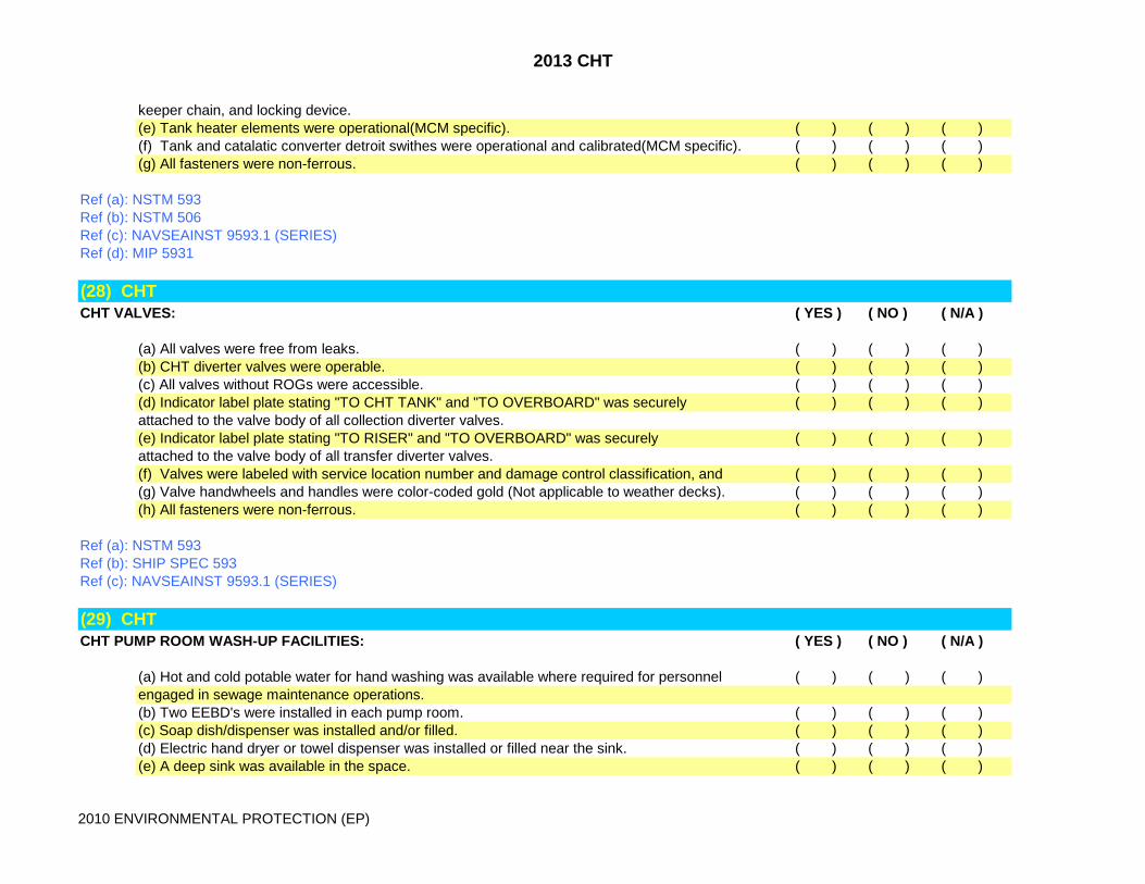
keeper chain, and locking device.(e) Tank heater elements were operational(MCM specific). ( ) ( ) ( )(f) Tank and catalatic converter detroit swithes were operational and calibrated(MCM specific). ( ) ( ) ( )(g) All fasteners were non-ferrous. ( ) ( ) ( )
Ref (a): NSTM 593Ref (b): NSTM 506Ref (c): NAVSEAINST 9593.1 (SERIES)Ref (d): MIP 5931
(28) CHTCHT VALVES: ( YES ) ( NO ) ( N/A )
(a) All valves were free from leaks. ( ) ( ) ( )(b) CHT diverter valves were operable. ( ) ( ) ( )(c) All valves without ROGs were accessible. ( ) ( ) ( )(d) Indicator label plate stating "TO CHT TANK" and "TO OVERBOARD" was securely ( ) ( ) ( )attached to the valve body of all collection diverter valves.(e) Indicator label plate stating "TO RISER" and "TO OVERBOARD" was securely ( ) ( ) ( )attached to the valve body of all transfer diverter valves.(f) Valves were labeled with service location number and damage control classification, and ( ) ( ) ( )(g) Valve handwheels and handles were color-coded gold (Not applicable to weather decks). ( ) ( ) ( )(h) All fasteners were non-ferrous. ( ) ( ) ( )
Ref (a): NSTM 593Ref (b): SHIP SPEC 593Ref (c): NAVSEAINST 9593.1 (SERIES)
(29) CHTCHT PUMP ROOM WASH-UP FACILITIES: ( YES ) ( NO ) ( N/A )
(a) Hot and cold potable water for hand washing was available where required for personnel ( ) ( ) ( )engaged in sewage maintenance operations. (b) Two EEBD's were installed in each pump room. ( ) ( ) ( )(c) Soap dish/dispenser was installed and/or filled. ( ) ( ) ( )(d) Electric hand dryer or towel dispenser was installed or filled near the sink. ( ) ( ) ( )(e) A deep sink was available in the space. ( ) ( ) ( )

2013 CHT
2010 ENVIRONMENTAL PROTECTION (EP)
(f) Betadine surgical soap (NSN 605-00-914-3593) was available in the space. ( ) ( ) ( )(g) Wescodyne disinfectant (NSN 6840-00-526-1129) was available in the space. ( ) ( ) ( )(h) Plastic trash can bags were available in the space. ( ) ( ) ( )(i) 3/4 inch wash down connection with vacuum breaker was installed. ( ) ( ) ( )(j) Hose was available for wash down of space. ( ) ( ) ( )
Ref (a): NSTM 593Ref (b): NAVMED P-5010Ref (c): NAVSEAINST 9593.1 (SERIES)Ref (d): OPNAVINST 5100.19 (SERIES)
(30) CHTCHT WATER CLOSETS/URINALS: ( YES ) ( NO ) ( N/A )
(a) Water closet/urinal flushometer was operable. ( ) ( ) ( )(b) Water closet/urinal flushometer cut out valve did not leak by. ( ) ( ) ( )(c) MCM Water closet/urinal flush pushbuttons inspected actuated M/T pump for 10-12 seconds. ( ) ( ) ( )(d) There was sufficient clearance for access to the water closet/urinal components. ( ) ( ) ( )(e) Water closet/urinal porcelain was free from chips or cracks. ( ) ( ) ( )(f) Water closet/urinal had flushing water pressure. ( ) ( ) ( )(g) Urinals had citric acid scale prevention tablets in the bowl to assist in prevention of hard pipe ( ) ( ) ( )scale buildup. (Tablet 9G-6810-01-362-0042) (Not req'd for MCM-1 class).(h) VCHT water closet discharge valve assembly was properly installed and free from air leaks. ( ) ( ) ( )(i) VCHT urinal vacuum interface valve assembly was properly installed and free from air leaks. ( ) ( ) ( )(j) VCHT water closet potable water flushing vacuum breaker was installed at least six ( ) ( ) ( )inches above the rim of the water closet.
Ref (a): NSTM 593Ref (b): NAVSEAINST 9593.1 (SERIES)
(31) CHTCHT/VCHT FLUSHING WATER REDUCING STATIONS: ( YES ) ( NO ) ( N/A )
(a) Relief valve was not leaking by. ( ) ( ) ( )(b) Relief valve hydrostatic test tag was present, set at correct psi and within periodicity. ( ) ( ) ( )(c) Reducing valve was set to the correct psi and adjusting bolt was not set to the extreme ( ) ( ) ( )lower position.
2013 CHT
2010 ENVIRONMENTAL PROTECTION (EP)
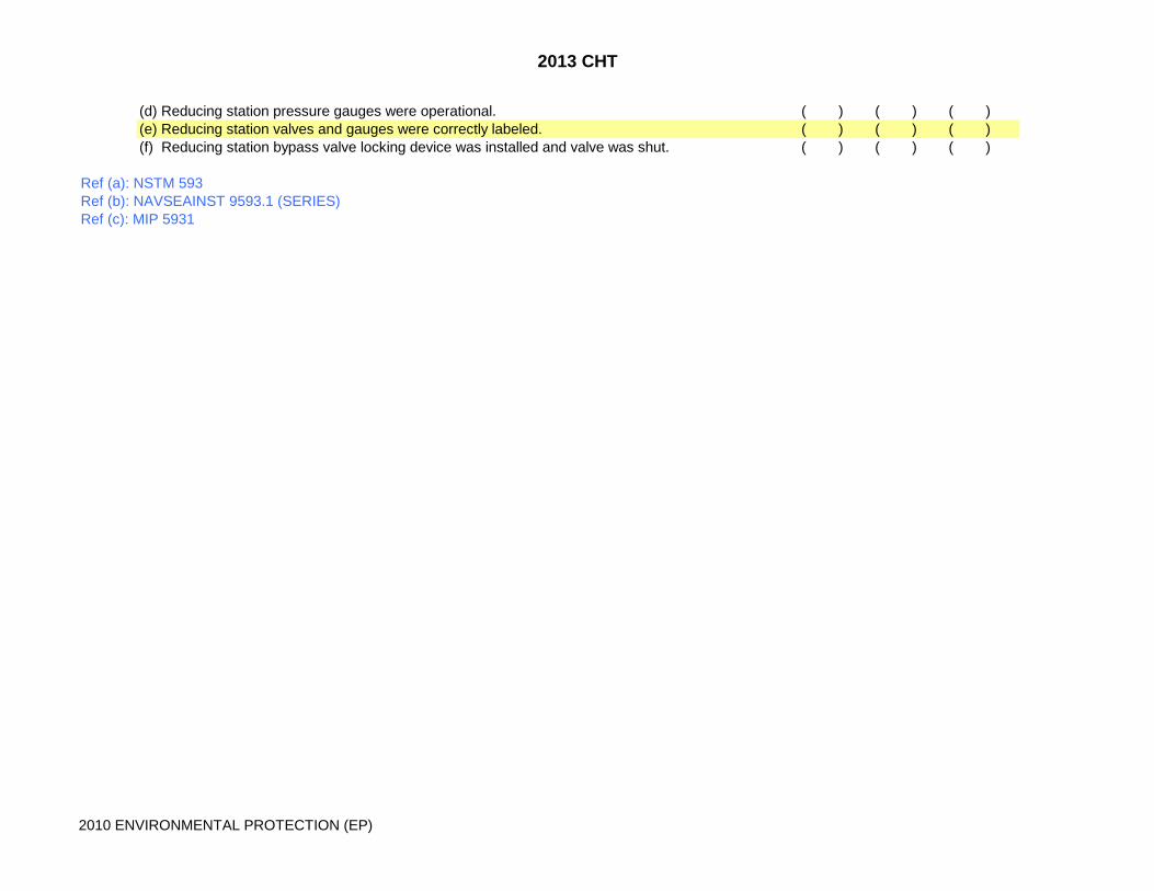
(d) Reducing station pressure gauges were operational. ( ) ( ) ( )(e) Reducing station valves and gauges were correctly labeled. ( ) ( ) ( )(f) Reducing station bypass valve locking device was installed and valve was shut. ( ) ( ) ( )
Ref (a): NSTM 593Ref (b): NAVSEAINST 9593.1 (SERIES)Ref (c): MIP 5931
2013 SOLID WASTE
2010 ENVIRONMENTAL PROTECTION (EP)
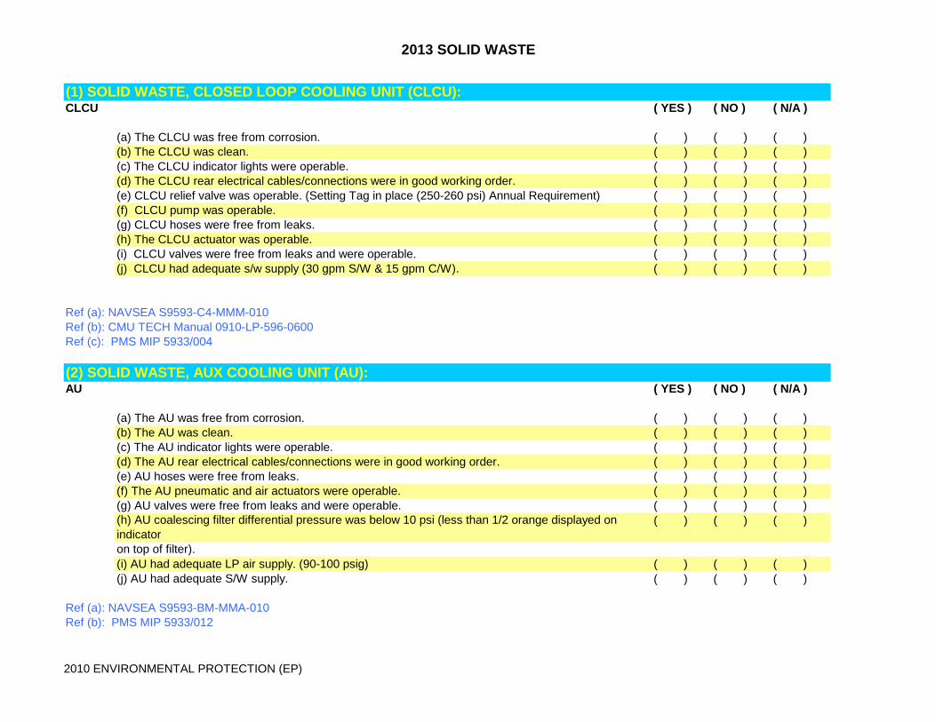
(1) SOLID WASTE, CLOSED LOOP COOLING UNIT (CLCU):CLCU ( YES ) ( NO ) ( N/A )
(a) The CLCU was free from corrosion. ( ) ( ) ( )(b) The CLCU was clean. ( ) ( ) ( )(c) The CLCU indicator lights were operable. ( ) ( ) ( )(d) The CLCU rear electrical cables/connections were in good working order. ( ) ( ) ( )(e) CLCU relief valve was operable. (Setting Tag in place (250-260 psi) Annual Requirement) ( ) ( ) ( )(f) CLCU pump was operable. ( ) ( ) ( )(g) CLCU hoses were free from leaks. ( ) ( ) ( )(h) The CLCU actuator was operable. ( ) ( ) ( )(i) CLCU valves were free from leaks and were operable. ( ) ( ) ( )(j) CLCU had adequate s/w supply (30 gpm S/W & 15 gpm C/W). ( ) ( ) ( )
Ref (a): NAVSEA S9593-C4-MMM-010Ref (b): CMU TECH Manual 0910-LP-596-0600Ref (c): PMS MIP 5933/004
(2) SOLID WASTE, AUX COOLING UNIT (AU):AU ( YES ) ( NO ) ( N/A )
(a) The AU was free from corrosion. ( ) ( ) ( )(b) The AU was clean. ( ) ( ) ( )(c) The AU indicator lights were operable. ( ) ( ) ( )(d) The AU rear electrical cables/connections were in good working order. ( ) ( ) ( )(e) AU hoses were free from leaks. ( ) ( ) ( )(f) The AU pneumatic and air actuators were operable. ( ) ( ) ( )(g) AU valves were free from leaks and were operable. ( ) ( ) ( )(h) AU coalescing filter differential pressure was below 10 psi (less than 1/2 orange displayed on indicator
( ) ( ) ( )
on top of filter).(i) AU had adequate LP air supply. (90-100 psig) ( ) ( ) ( )(j) AU had adequate S/W supply. ( ) ( ) ( )
Ref (a): NAVSEA S9593-BM-MMA-010Ref (b): PMS MIP 5933/012
2013 SOLID WASTE
2010 ENVIRONMENTAL PROTECTION (EP)
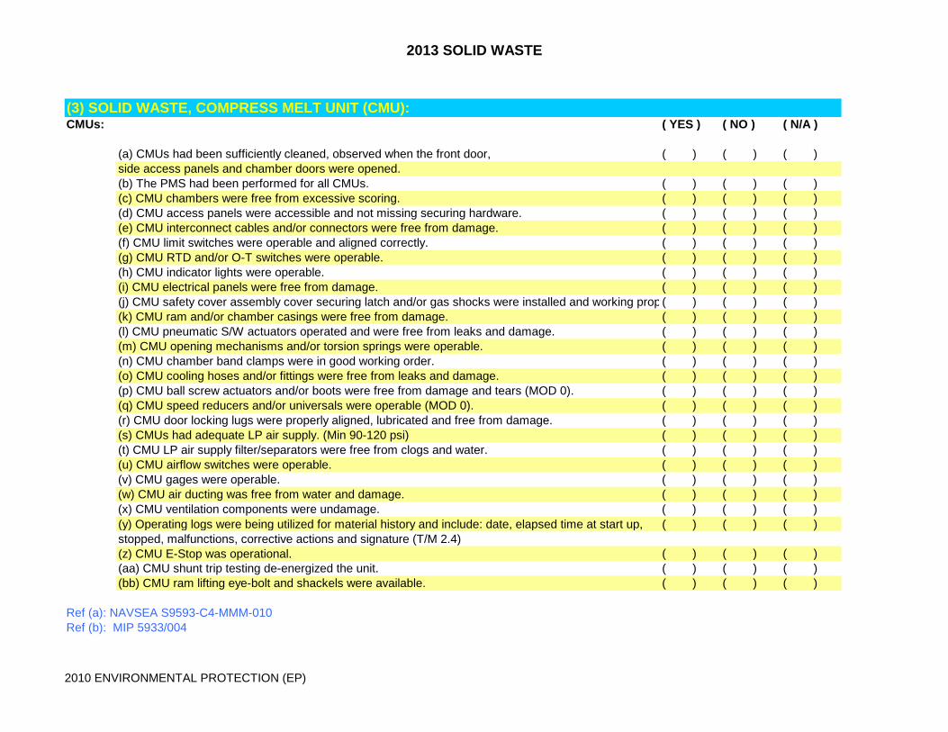
(3) SOLID WASTE, COMPRESS MELT UNIT (CMU):CMUs: ( YES ) ( NO ) ( N/A )
(a) CMUs had been sufficiently cleaned, observed when the front door, ( ) ( ) ( )side access panels and chamber doors were opened.(b) The PMS had been performed for all CMUs. ( ) ( ) ( )(c) CMU chambers were free from excessive scoring. ( ) ( ) ( )(d) CMU access panels were accessible and not missing securing hardware. ( ) ( ) ( )(e) CMU interconnect cables and/or connectors were free from damage. ( ) ( ) ( )(f) CMU limit switches were operable and aligned correctly. ( ) ( ) ( )(g) CMU RTD and/or O-T switches were operable. ( ) ( ) ( )(h) CMU indicator lights were operable. ( ) ( ) ( )(i) CMU electrical panels were free from damage. ( ) ( ) ( )(j) CMU safety cover assembly cover securing latch and/or gas shocks were installed and working prop ( ) ( ) ( )(k) CMU ram and/or chamber casings were free from damage. ( ) ( ) ( )(l) CMU pneumatic S/W actuators operated and were free from leaks and damage. ( ) ( ) ( )(m) CMU opening mechanisms and/or torsion springs were operable. ( ) ( ) ( )(n) CMU chamber band clamps were in good working order. ( ) ( ) ( )(o) CMU cooling hoses and/or fittings were free from leaks and damage. ( ) ( ) ( )(p) CMU ball screw actuators and/or boots were free from damage and tears (MOD 0). ( ) ( ) ( )(q) CMU speed reducers and/or universals were operable (MOD 0). ( ) ( ) ( )(r) CMU door locking lugs were properly aligned, lubricated and free from damage. ( ) ( ) ( )(s) CMUs had adequate LP air supply. (Min 90-120 psi) ( ) ( ) ( )(t) CMU LP air supply filter/separators were free from clogs and water. ( ) ( ) ( )(u) CMU airflow switches were operable. ( ) ( ) ( )(v) CMU gages were operable. ( ) ( ) ( )(w) CMU air ducting was free from water and damage. ( ) ( ) ( )(x) CMU ventilation components were undamage. ( ) ( ) ( )(y) Operating logs were being utilized for material history and include: date, elapsed time at start up, ( ) ( ) ( )stopped, malfunctions, corrective actions and signature (T/M 2.4)(z) CMU E-Stop was operational. ( ) ( ) ( )(aa) CMU shunt trip testing de-energized the unit. ( ) ( ) ( )(bb) CMU ram lifting eye-bolt and shackels were available. ( ) ( ) ( )
Ref (a): NAVSEA S9593-C4-MMM-010Ref (b): MIP 5933/004

2013 SOLID WASTE
2010 ENVIRONMENTAL PROTECTION (EP)
Ref (c) S9593-BM-MMA-010 MOD 1
(4) SOLID WASTE, DOCUMENT DESTRUCTOR:DOC DESTRUCTOR: ( YES ) ( NO ) ( N/A )
(a) The fresh water washdown hose and hose rack were installed and available. ( ) ( ) ( )(b) Document destructor was operating properly. ( ) ( ) ( )(c) Cutting teeth were free from rust and corrosion. ( ) ( ) ( )(d) Fresh water washdown threaded hose connection had an installed backflow preventor. ( ) ( ) ( )(e) Placard regarding discharge restrictions was posted near destructor. ( ) ( ) ( )(f) Feed chute safety interlock was operational. ( ) ( ) ( )
Ref (a): NAVSEA 0936-LP-039-7010; 0936-039-7010; 0936-LP-039-9010Ref (b): SHIPSPEC 593Ref (c): PMS MIP 6561/007
(5) SOLID WASTE, EQUIPMENT ILS:EQUIP ILS: ( YES ) ( NO ) ( N/A )
(a) Operating instructions/precautions were posted for the (plastics or metal/glass) schredder, ( ) ( ) ( )compress melt unit, large or small pulper, document destructor.(b) Tech manuals were available for the pulper, schredders, compress melt units and document destructor.
( ) ( ) ( )
(c) PMS installed for the pulper, shredders, compressed melt units and document destructor. ( ) ( ) ( )NOTE: PMS is a split MIP that should be covered by E-Div, A-gang and Supply Department.
Ref (a): NAVSEA TECH MANUAL 0936-LP-039-7 DOCUMENT DESTRUCTORRef (b): NAVSEA TECH MANUAL S9593-C5-MMM-010 & S9593-DP-MMA-010 SOLID/PLASTIC SHREDDERRef ( c): NAVSEA TECH MANUAL S9593-BM-MMA-010 & S9593 C4-MMM-010 CMU MOD O AND MOD 1Ref (d): NAVSEA TECH MANUAL S9593-C2-MMM-010 & S9593-C3-MMM-010 PULPER, SM AND LG
(6) SOLID WASTE, GLASS/METAL SHREDDER:GLASS/METAL SHREDDER: ( YES ) ( NO ) ( N/A )
(a) Was properly installed. ( ) ( ) ( )(b) The exterior was free from damage. ( ) ( ) ( )(c) Sorting tray was in place and in good working order. ( ) ( ) ( )
2013 SOLID WASTE
2010 ENVIRONMENTAL PROTECTION (EP)
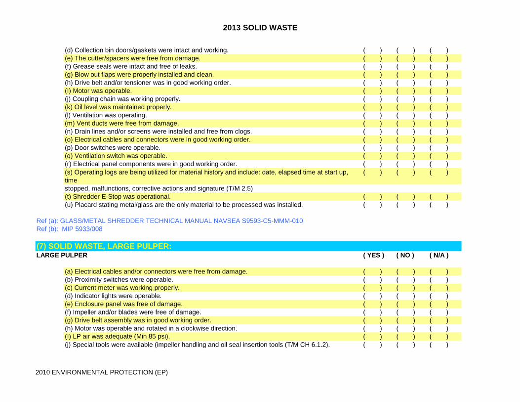
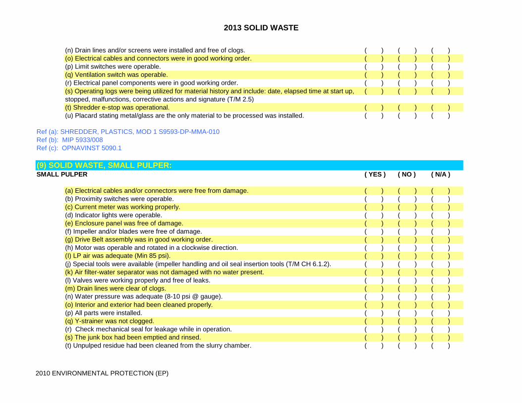
(d) Collection bin doors/gaskets were intact and working. ( ) ( ) ( )(e) The cutter/spacers were free from damage. ( ) ( ) ( )(f) Grease seals were intact and free of leaks. ( ) ( ) ( )(g) Blow out flaps were properly installed and clean. ( ) ( ) ( )(h) Drive belt and/or tensioner was in good working order. ( ) ( ) ( )(I) Motor was operable. ( ) ( ) ( )(j) Coupling chain was working properly. ( ) ( ) ( )(k) Oil level was maintained properly. ( ) ( ) ( )(l) Ventilation was operating. ( ) ( ) ( )(m) Vent ducts were free from damage. ( ) ( ) ( )(n) Drain lines and/or screens were installed and free from clogs. ( ) ( ) ( )(o) Electrical cables and connectors were in good working order. ( ) ( ) ( )(p) Door switches were operable. ( ) ( ) ( )(q) Ventilation switch was operable. ( ) ( ) ( )(r) Electrical panel components were in good working order. ( ) ( ) ( )(s) Operating logs are being utilized for material history and include: date, elapsed time at start up, time
( ) ( ) ( )
stopped, malfunctions, corrective actions and signature (T/M 2.5)(t) Shredder E-Stop was operational. ( ) ( ) ( )(u) Placard stating metal/glass are the only material to be processed was installed. ( ) ( ) ( )
Ref (a): GLASS/METAL SHREDDER TECHNICAL MANUAL NAVSEA S9593-C5-MMM-010Ref (b): MIP 5933/008
(7) SOLID WASTE, LARGE PULPER:LARGE PULPER ( YES ) ( NO ) ( N/A )
(a) Electrical cables and/or connectors were free from damage. ( ) ( ) ( )(b) Proximity switches were operable. ( ) ( ) ( )(c) Current meter was working properly. ( ) ( ) ( )(d) Indicator lights were operable. ( ) ( ) ( )(e) Enclosure panel was free of damage. ( ) ( ) ( )(f) Impeller and/or blades were free of damage. ( ) ( ) ( )(g) Drive belt assembly was in good working order. ( ) ( ) ( )(h) Motor was operable and rotated in a clockwise direction. ( ) ( ) ( )(I) LP air was adequate (Min 85 psi). ( ) ( ) ( )(j) Special tools were available (impeller handling and oil seal insertion tools (T/M CH 6.1.2). ( ) ( ) ( )
2013 SOLID WASTE
2010 ENVIRONMENTAL PROTECTION (EP)
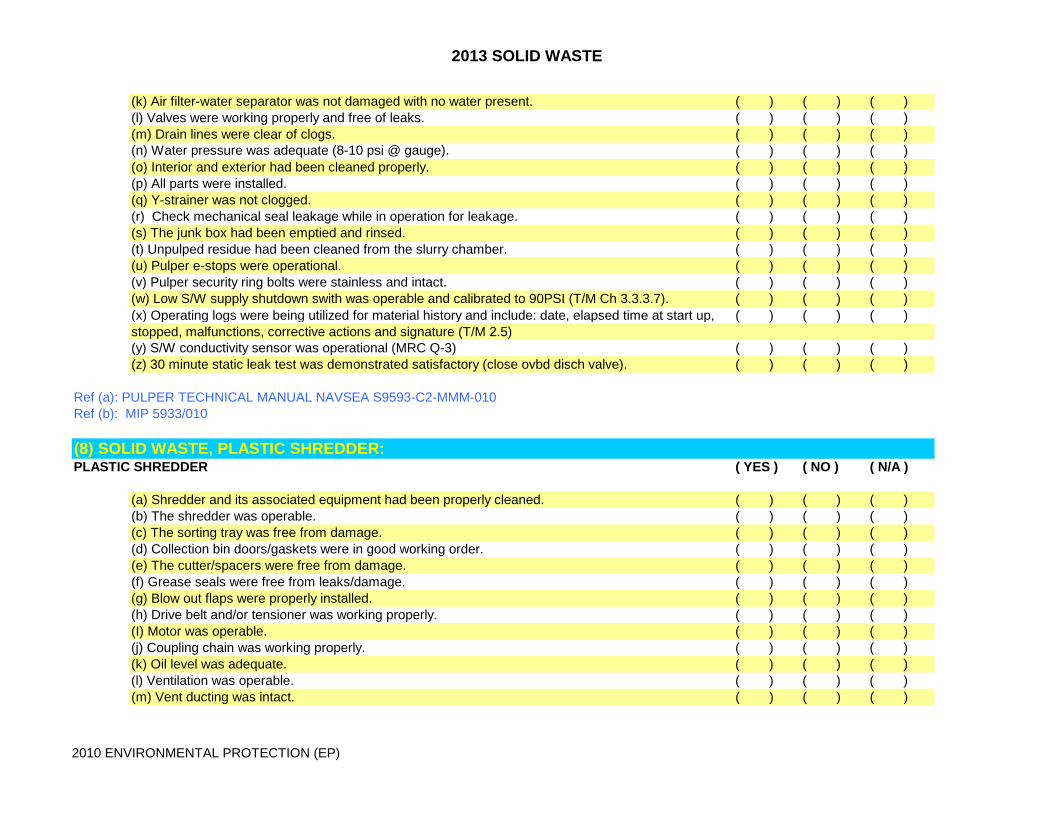
(k) Air filter-water separator was not damaged with no water present. ( ) ( ) ( )(l) Valves were working properly and free of leaks. ( ) ( ) ( )(m) Drain lines were clear of clogs. ( ) ( ) ( )(n) Water pressure was adequate (8-10 psi @ gauge). ( ) ( ) ( )(o) Interior and exterior had been cleaned properly. ( ) ( ) ( )(p) All parts were installed. ( ) ( ) ( )(q) Y-strainer was not clogged. ( ) ( ) ( )(r) Check mechanical seal leakage while in operation for leakage. ( ) ( ) ( )(s) The junk box had been emptied and rinsed. ( ) ( ) ( )(t) Unpulped residue had been cleaned from the slurry chamber. ( ) ( ) ( )(u) Pulper e-stops were operational. ( ) ( ) ( )(v) Pulper security ring bolts were stainless and intact. ( ) ( ) ( )(w) Low S/W supply shutdown swith was operable and calibrated to 90PSI (T/M Ch 3.3.3.7). ( ) ( ) ( )(x) Operating logs were being utilized for material history and include: date, elapsed time at start up, ( ) ( ) ( )stopped, malfunctions, corrective actions and signature (T/M 2.5)(y) S/W conductivity sensor was operational (MRC Q-3) ( ) ( ) ( )(z) 30 minute static leak test was demonstrated satisfactory (close ovbd disch valve). ( ) ( ) ( )
Ref (a): PULPER TECHNICAL MANUAL NAVSEA S9593-C2-MMM-010Ref (b): MIP 5933/010
(8) SOLID WASTE, PLASTIC SHREDDER:PLASTIC SHREDDER ( YES ) ( NO ) ( N/A )
(a) Shredder and its associated equipment had been properly cleaned. ( ) ( ) ( )(b) The shredder was operable. ( ) ( ) ( )(c) The sorting tray was free from damage. ( ) ( ) ( )(d) Collection bin doors/gaskets were in good working order. ( ) ( ) ( )(e) The cutter/spacers were free from damage. ( ) ( ) ( )(f) Grease seals were free from leaks/damage. ( ) ( ) ( )(g) Blow out flaps were properly installed. ( ) ( ) ( )(h) Drive belt and/or tensioner was working properly. ( ) ( ) ( )(I) Motor was operable. ( ) ( ) ( )(j) Coupling chain was working properly. ( ) ( ) ( )(k) Oil level was adequate. ( ) ( ) ( )(l) Ventilation was operable. ( ) ( ) ( )(m) Vent ducting was intact. ( ) ( ) ( )
2013 SOLID WASTE
2010 ENVIRONMENTAL PROTECTION (EP)
(n) Drain lines and/or screens were installed and free of clogs. ( ) ( ) ( )(o) Electrical cables and connectors were in good working order. ( ) ( ) ( )(p) Limit switches were operable. ( ) ( ) ( )(q) Ventilation switch was operable. ( ) ( ) ( )(r) Electrical panel components were in good working order. ( ) ( ) ( )(s) Operating logs were being utilized for material history and include: date, elapsed time at start up, ( ) ( ) ( )stopped, malfunctions, corrective actions and signature (T/M 2.5)(t) Shredder e-stop was operational. ( ) ( ) ( )(u) Placard stating metal/glass are the only material to be processed was installed. ( ) ( ) ( )
Ref (a): SHREDDER, PLASTICS, MOD 1 S9593-DP-MMA-010Ref (b): MIP 5933/008Ref (c): OPNAVINST 5090.1
(9) SOLID WASTE, SMALL PULPER:SMALL PULPER ( YES ) ( NO ) ( N/A )
(a) Electrical cables and/or connectors were free from damage. ( ) ( ) ( )(b) Proximity switches were operable. ( ) ( ) ( )(c) Current meter was working properly. ( ) ( ) ( )(d) Indicator lights were operable. ( ) ( ) ( )(e) Enclosure panel was free of damage. ( ) ( ) ( )(f) Impeller and/or blades were free of damage. ( ) ( ) ( )(g) Drive Belt assembly was in good working order. ( ) ( ) ( )(h) Motor was operable and rotated in a clockwise direction. ( ) ( ) ( )(I) LP air was adequate (Min 85 psi). ( ) ( ) ( )(j) Special tools were available (impeller handling and oil seal insertion tools (T/M CH 6.1.2). ( ) ( ) ( )(k) Air filter-water separator was not damaged with no water present. ( ) ( ) ( )(l) Valves were working properly and free of leaks. ( ) ( ) ( )(m) Drain lines were clear of clogs. ( ) ( ) ( )(n) Water pressure was adequate (8-10 psi @ gauge). ( ) ( ) ( )(o) Interior and exterior had been cleaned properly. ( ) ( ) ( )(p) All parts were installed. ( ) ( ) ( )(q) Y-strainer was not clogged. ( ) ( ) ( )(r) Check mechanical seal for leakage while in operation. ( ) ( ) ( )(s) The junk box had been emptied and rinsed. ( ) ( ) ( )(t) Unpulped residue had been cleaned from the slurry chamber. ( ) ( ) ( )
2013 SOLID WASTE
2010 ENVIRONMENTAL PROTECTION (EP)
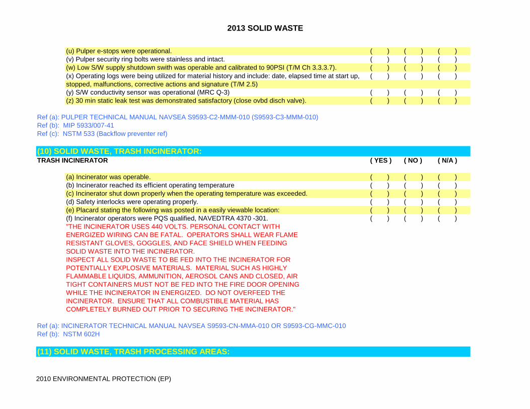
(u) Pulper e-stops were operational. ( ) ( ) ( )(v) Pulper security ring bolts were stainless and intact. ( ) ( ) ( )(w) Low S/W supply shutdown swith was operable and calibrated to 90PSI (T/M Ch 3.3.3.7). ( ) ( ) ( )(x) Operating logs were being utilized for material history and include: date, elapsed time at start up, ( ) ( ) ( )stopped, malfunctions, corrective actions and signature (T/M 2.5)(y) S/W conductivity sensor was operational (MRC Q-3) ( ) ( ) ( )(z) 30 min static leak test was demonstrated satisfactory (close ovbd disch valve). ( ) ( ) ( )
Ref (a): PULPER TECHNICAL MANUAL NAVSEA S9593-C2-MMM-010 (S9593-C3-MMM-010)Ref (b): MIP 5933/007-41Ref (c): NSTM 533 (Backflow preventer ref)
(10) SOLID WASTE, TRASH INCINERATOR:TRASH INCINERATOR ( YES ) ( NO ) ( N/A )
(a) Incinerator was operable. ( ) ( ) ( )(b) Incinerator reached its efficient operating temperature ( ) ( ) ( )(c) Incinerator shut down properly when the operating temperature was exceeded. ( ) ( ) ( )(d) Safety interlocks were operating properly. ( ) ( ) ( )(e) Placard stating the following was posted in a easily viewable location: ( ) ( ) ( )(f) Incinerator operators were PQS qualified, NAVEDTRA 4370 -301. ( ) ( ) ( )"THE INCINERATOR USES 440 VOLTS. PERSONAL CONTACT WITHENERGIZED WIRING CAN BE FATAL. OPERATORS SHALL WEAR FLAMERESISTANT GLOVES, GOGGLES, AND FACE SHIELD WHEN FEEDING SOLID WASTE INTO THE INCINERATOR.INSPECT ALL SOLID WASTE TO BE FED INTO THE INCINERATOR FOR POTENTIALLY EXPLOSIVE MATERIALS. MATERIAL SUCH AS HIGHLYFLAMMABLE LIQUIDS, AMMUNITION, AEROSOL CANS AND CLOSED, AIRTIGHT CONTAINERS MUST NOT BE FED INTO THE FIRE DOOR OPENINGWHILE THE INCINERATOR IN ENERGIZED. DO NOT OVERFEED THE INCINERATOR. ENSURE THAT ALL COMBUSTIBLE MATERIAL HAS COMPLETELY BURNED OUT PRIOR TO SECURING THE INCINERATOR."
Ref (a): INCINERATOR TECHNICAL MANUAL NAVSEA S9593-CN-MMA-010 OR S9593-CG-MMC-010Ref (b): NSTM 602H
(11) SOLID WASTE, TRASH PROCESSING AREAS:
2013 SOLID WASTE
2010 ENVIRONMENTAL PROTECTION (EP)
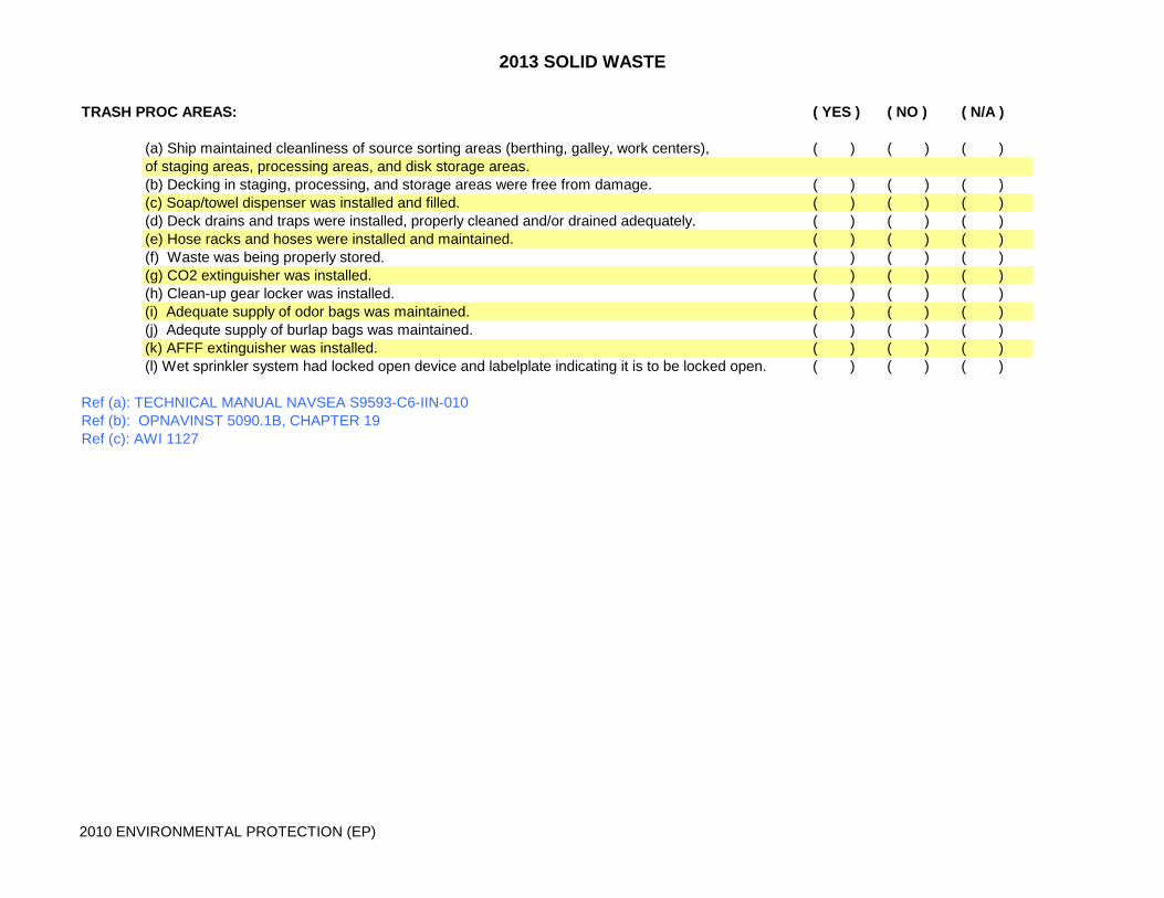
TRASH PROC AREAS: ( YES ) ( NO ) ( N/A )
(a) Ship maintained cleanliness of source sorting areas (berthing, galley, work centers), ( ) ( ) ( )of staging areas, processing areas, and disk storage areas.(b) Decking in staging, processing, and storage areas were free from damage. ( ) ( ) ( )(c) Soap/towel dispenser was installed and filled. ( ) ( ) ( )(d) Deck drains and traps were installed, properly cleaned and/or drained adequately. ( ) ( ) ( )(e) Hose racks and hoses were installed and maintained. ( ) ( ) ( )(f) Waste was being properly stored. ( ) ( ) ( )(g) CO2 extinguisher was installed. ( ) ( ) ( )(h) Clean-up gear locker was installed. ( ) ( ) ( )(i) Adequate supply of odor bags was maintained. ( ) ( ) ( )(j) Adequte supply of burlap bags was maintained. ( ) ( ) ( )(k) AFFF extinguisher was installed. ( ) ( ) ( )(l) Wet sprinkler system had locked open device and labelplate indicating it is to be locked open. ( ) ( ) ( )
Ref (a): TECHNICAL MANUAL NAVSEA S9593-C6-IIN-010Ref (b): OPNAVINST 5090.1B, CHAPTER 19Ref (c): AWI 1127
2013 EP PROGRAM
2010 ENVIRONMENTAL PROTECTION (EP)
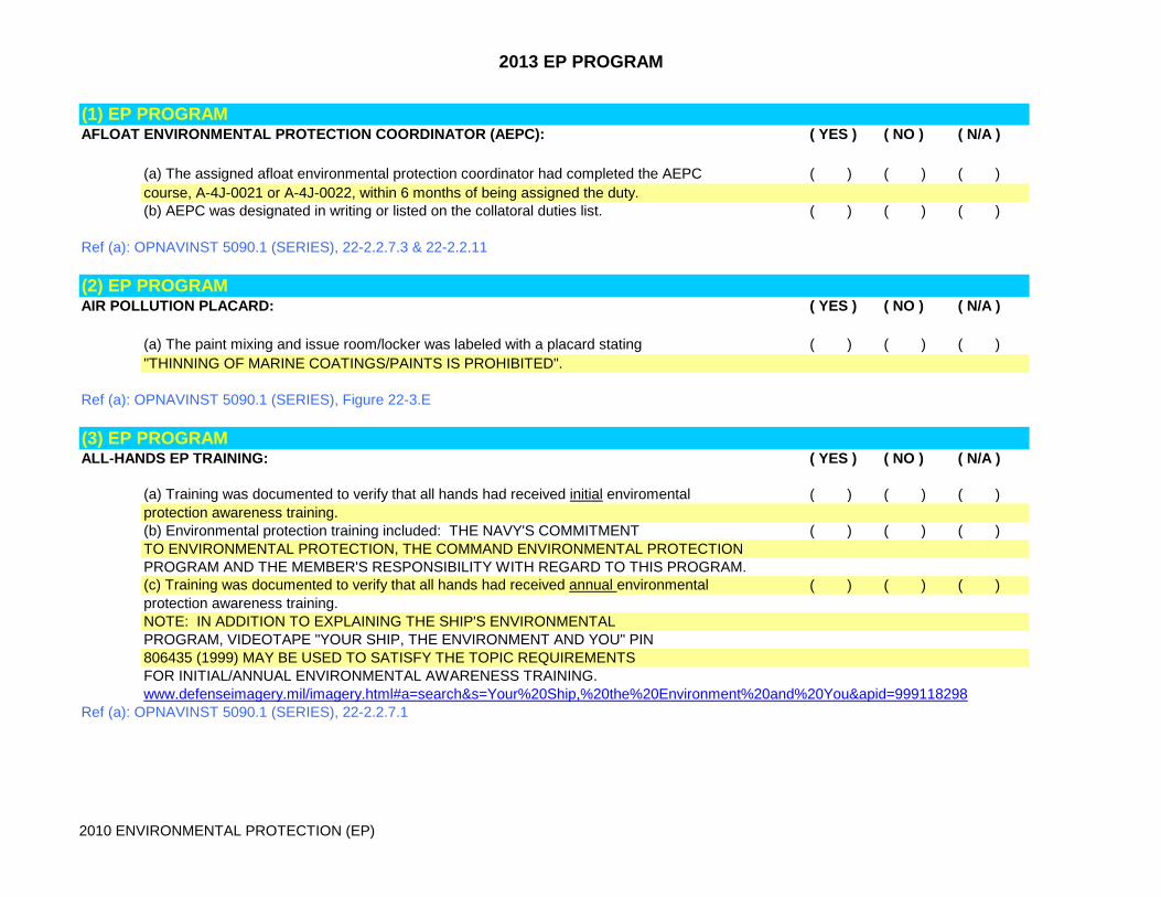
(1) EP PROGRAM AFLOAT ENVIRONMENTAL PROTECTION COORDINATOR (AEPC): ( YES ) ( NO ) ( N/A )
(a) The assigned afloat environmental protection coordinator had completed the AEPC ( ) ( ) ( )course, A-4J-0021 or A-4J-0022, within 6 months of being assigned the duty.(b) AEPC was designated in writing or listed on the collatoral duties list. ( ) ( ) ( )
Ref (a): OPNAVINST 5090.1 (SERIES), 22-2.2.7.3 & 22-2.2.11
(2) EP PROGRAM AIR POLLUTION PLACARD: ( YES ) ( NO ) ( N/A )
(a) The paint mixing and issue room/locker was labeled with a placard stating ( ) ( ) ( )"THINNING OF MARINE COATINGS/PAINTS IS PROHIBITED".
Ref (a): OPNAVINST 5090.1 (SERIES), Figure 22-3.E
(3) EP PROGRAM ALL-HANDS EP TRAINING: ( YES ) ( NO ) ( N/A )
(a) Training was documented to verify that all hands had received initial enviromental ( ) ( ) ( )protection awareness training.(b) Environmental protection training included: THE NAVY'S COMMITMENT ( ) ( ) ( )TO ENVIRONMENTAL PROTECTION, THE COMMAND ENVIRONMENTAL PROTECTIONPROGRAM AND THE MEMBER'S RESPONSIBILITY WITH REGARD TO THIS PROGRAM.(c) Training was documented to verify that all hands had received annual environmental ( ) ( ) ( )protection awareness training.NOTE: IN ADDITION TO EXPLAINING THE SHIP'S ENVIRONMENTALPROGRAM, VIDEOTAPE "YOUR SHIP, THE ENVIRONMENT AND YOU" PIN806435 (1999) MAY BE USED TO SATISFY THE TOPIC REQUIREMENTSFOR INITIAL/ANNUAL ENVIRONMENTAL AWARENESS TRAINING.www.defenseimagery.mil/imagery.html#a=search&s=Your%20Ship,%20the%20Environment%20and%20You&apid=999118298
Ref (a): OPNAVINST 5090.1 (SERIES), 22-2.2.7.1

2013 EP PROGRAM
2010 ENVIRONMENTAL PROTECTION (EP)
(4) EP PROGRAM CHT SYSTEM CERTIFICATION: ( YES ) ( NO ) ( N/A )
(a) The CHT system was certified. (Issued at sea trials, recertification required after major alteration). ( ) ( ) ( )
Ref (a): OPNAVINST 5090.1 (SERIES), 22-15.11.1Ref (b): NSTM 593Ref (c): SHIP SPEC 593 (AT/FCT)
(5) EP PROGRAM CHT SYSTEM TRAINING/QUALIFICATION: ( YES ) ( NO ) ( N/A )
(a) Personnel who operated/maintained CHT equipment were trained in proper ( ) ( ) ( )procedures for sewage/graywater disposal, including hookup and transfer of sewage orgraywater to shore facilities and at sea discharge restrictions. (b) Duty sections were adequately supplied with PQS (43199) qualified sewage system operators ( ) ( ) ( )for type of sewage system on board.(c) Ship maintains at least one PQS qualified Sewage Disposal Officer. ( ) ( ) ( )
Ref (a): OPNAVINST 5090.1 (SERIES), 22.3.4Ref (b): NAVEDTRA 43199 (SERIES)
(6) EP PROGRAM ENVIRONMENTAL COMPLIANCE BOARD: ( YES ) ( NO ) ( N/A )
(a) The environmental compliance board consisted of the XO, safety officer, ( ) ( ) ( )dept heads, AEPC, legal officer and CMC.
Ref (a): OPNAVINST 3120.32 (SERIES), SEC. 304.26
(7) EP PROGRAM ODS DOCUMENTATION AND LOGS: ( YES ) ( NO ) ( N/A )
(a) Ship maintained a log/records of added and recovered or removed refrigerants, ( ) ( ) ( )and record of leakages (3 YEARS).(b) Ship completed/maintained accidental or unintentional venting reports (3 YEARS). ( ) ( ) ( )
2013 EP PROGRAM
2010 ENVIRONMENTAL PROTECTION (EP)
Ref (a): OPNAVINST 5090.1 (SERIES), 22-4.3.2.5 & 22-4.3.2.7Ref (b): NSTM 516, ARTICLE 516-1.11, FIG 516-1-9 AND 1-10Ref (c): PMS MIP: 5140/5161
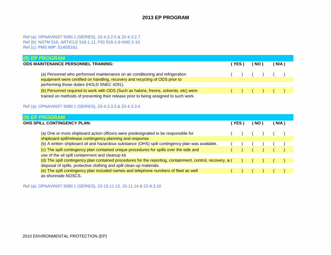
(8) EP PROGRAM ODS MAINTENANCE PERSONNEL TRAINING: ( YES ) ( NO ) ( N/A )
(a) Personnel who performed maintenance on air conditioning and refrigeration ( ) ( ) ( )equipment were certified on handling, recovery and recycling of ODS prior toperforming those duties (HOLD SNEC 4291).(b) Personnel required to work with ODS (Such as halons, freons, solvents, etc) were ( ) ( ) ( )trained on methods of preventing their release prior to being assigned to such work.
Ref (a): OPNAVINST 5090.1 (SERIES), 22-4.3.3.3 & 22-4.3.3.4
(9) EP PROGRAM OHS SPILL CONTINGENCY PLAN: ( YES ) ( NO ) ( N/A )
(a) One or more shipboard action officers were predesignated to be responsible for ( ) ( ) ( )shipboard spill/release contingency planning and response.(b) A written shipboard oil and hazardous substance (OHS) spill contingency plan was available. ( ) ( ) ( )(c) The spill contingency plan contained unique procedures for spills over the side and ( ) ( ) ( )use of the oil spill containment and cleanup kit.(d) The spill contingency plan contained procedures for the reporting, containment, control, recovery, an( ) ( ) ( )disposal of spills, protective clothing and spill clean-up materials.(e) The spill contingency plan included names and telephone numbers of fleet as well ( ) ( ) ( )as shoreside NOSCS.
Ref (a): OPNAVINST 5090.1 (SERIES), 22-15.11.13, 15-11.14 & 22-9.2.10

2013 EP PROGRAM
2010 ENVIRONMENTAL PROTECTION (EP)
(10) EP PROGRAM OHS SPILL TRAINING/QUALIFICATION: ( YES ) ( NO ) ( N/A )
(a) Inport watchstanders and command duty officers were trained on inport OHS spill ( ) ( ) ( )response procedures, the ship's SCP, and local notification requirements prior to assignment.(b) One Petty Officer per duty section or repair party was qualified on watchstation NAVEDTRA ( ) ( ) ( )43704-324 Oil Spill Clean-up Supervisor.(c) An over-the side oil/hazardous spill drill was conducted for each duty section at least annually. ( ) ( ) ( )(d) The OHS spill drill included use of the oil spill containment and cleanup kit and ( ) ( ) ( )exercised notification practices and simulated message drafting.
Ref (a): OPNAVINST 5090.1 (SERIES) 22-15.11.15 & 22-9.3.1Ref (b): NAVEDTRA 43704 (SERIES)
(11) EP PROGRAM OPA SYSTEM TRAINING/QUALIFICATION: ( YES ) ( NO ) ( N/A )
(a) Personnel assigned to supervise oily waste processing and disposal operations ( ) ( ) ( )had completed the formal oil pollution abatement (OPA) equipment operation and maintenance course, K-652-2196, prior to assuming the duties.(b) Personnel assigned to operate/maintain OPA equipment were trained in proper operating ( ) ( ) ( )procedures, shore hook-up and transfer, proper shore disposal, and at-sea discharge restrictions.(c) All personnel who operate or maintian the OWS system were qualified NAVEDTRA ( ) ( ) ( )43704-302 Oil Transfer Team Member/Spill Prevention Team.
Ref (a): OPNAVINST 5090.1 (SERIES), 22-5.5Ref (b): NAVEDTRA 43704 (SERIES)

2013 EP PROGRAM
2010 ENVIRONMENTAL PROTECTION (EP)
(12) EP PROGRAM SOLID WASTE EQUIP TRAINING/QUALIFICATION: ( YES ) ( NO ) ( N/A )
(a) Operators and personnel who maintain solid waste equipment were qualified NAVEDTRA ( ) ( ) ( )43704, 301 (CMUs), 303 (Pulpers), 304 & 305 (Shredders).(b) Ship had available solid waste equipment operators PQS. ( ) ( ) ( )(c) Documentation was available to verify that personnel responsible for handling ships ( ) ( ) ( )garbage were trained on the discharge restrictions applicable to the waste prior to assignment.
Ref (a): OPNAVINST 1540.55Ref (b): OPNAVINST 5090.1 (SERIES), 22-7.4.3Ref (c): NAVEDTRA 43704 (SERIES)

2013 EP PROGRAM
2010 ENVIRONMENTAL PROTECTION (EP)
(1) POLLUTION PREVENTION CABLE CLEANER/LUBRICATOR: ( YES ) ( NO ) ( N/A )
(a) Was the cable cleaner/lubricator properly cleaned after use (all parts can be cleaned in the ( ) ( ) ( )aqueous parts washer)?(b) Did the cable cleaner/lubricator have all of its required parts? ( ) ( ) ( )(c) The cable cleaner/lubricator technical manual was on board? ( ) ( ) ( )
Ref (b): Technical Manual S9582-BH-MMC-010.Ref (c): APL 658880017, NSN 4930-01-424-2197
NOTE: Technical Sponsor for assistance on P2 equipment is NSWCCD Code 632 at (215) 897-1081 or (301) 227-5243(2) POLLUTION PREVENTIONLARGE AQUEOUS PARTS WASHER ( YES ) ( NO ) ( N/A )
(a) The parts washer was operable. ( ) ( ) ( )(b) PMS was installed and accomplished. ( ) ( ) ( )(c) Water level was greater than 11 inches. ( ) ( ) ( )(d) Filterchip basket was installed and was cleaned out. ( ) ( ) ( )(e) The oil skimmer was operable. ( ) ( ) ( )(f) Exhaust ventilation was attached and working properly. ( ) ( ) ( )(g) The parts washer was clean and free of debris. ( ) ( ) ( )(h) Pressure drop across the filter bag was less than 10 psi. ( ) ( ) ( )(i) The sludge level was less than 1 inch. ( ) ( ) ( )(j) The technical manual was maintained on board. ( ) ( ) ( )(k) The titration kit was maintained. ( ) ( ) ( )(l) The parts washer was properly placed in lay-up. ( ) ( ) ( )(m) The door gasket was not damaged or missing. ( ) ( ) ( )(n) Door latch and limit switch were operational. ( ) ( ) ( )(o) The parts washer maintained an operating temperature of 185-200 degrees. ( ) ( ) ( )
Ref (a): Executive Order 12856Ref (c): NAVAIR 17-5-7Ref (d): PMS MIP 6613/034Ref (e): APL 419990368 (Power Panel APL 509991881), NSN 4940-01-435-1595
NOTE: Technical Sponsor for assistance on P2 equipment is NSWCCD Code 632 at (215) 897-1081 or (301) 227-5243
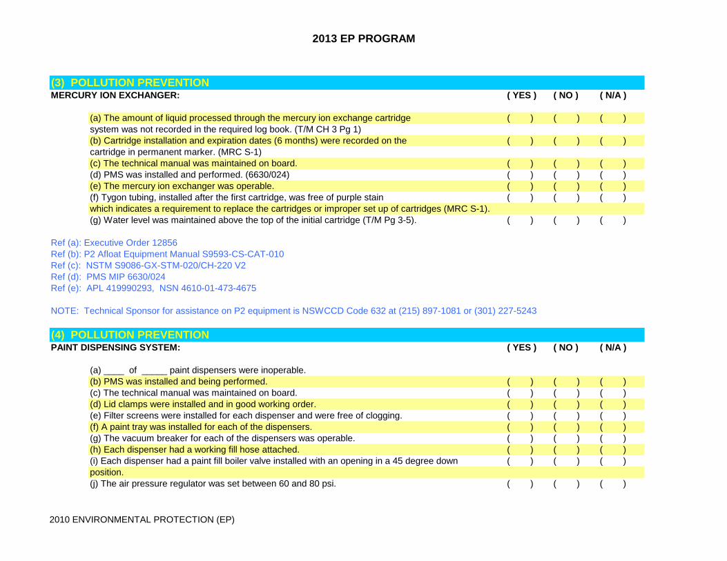
2013 EP PROGRAM
2010 ENVIRONMENTAL PROTECTION (EP)
(3) POLLUTION PREVENTIONMERCURY ION EXCHANGER: ( YES ) ( NO ) ( N/A )
(a) The amount of liquid processed through the mercury ion exchange cartridge ( ) ( ) ( )system was not recorded in the required log book. (T/M CH 3 Pg 1)(b) Cartridge installation and expiration dates (6 months) were recorded on the ( ) ( ) ( )cartridge in permanent marker. (MRC S-1)(c) The technical manual was maintained on board. ( ) ( ) ( )(d) PMS was installed and performed. (6630/024) ( ) ( ) ( )(e) The mercury ion exchanger was operable. ( ) ( ) ( )(f) Tygon tubing, installed after the first cartridge, was free of purple stain ( ) ( ) ( )which indicates a requirement to replace the cartridges or improper set up of cartridges (MRC S-1).(g) Water level was maintained above the top of the initial cartridge (T/M Pg 3-5). ( ) ( ) ( )
Ref (a): Executive Order 12856Ref (b): P2 Afloat Equipment Manual S9593-CS-CAT-010Ref (c): NSTM S9086-GX-STM-020/CH-220 V2Ref (d): PMS MIP 6630/024Ref (e): APL 419990293, NSN 4610-01-473-4675
NOTE: Technical Sponsor for assistance on P2 equipment is NSWCCD Code 632 at (215) 897-1081 or (301) 227-5243
(4) POLLUTION PREVENTIONPAINT DISPENSING SYSTEM: ( YES ) ( NO ) ( N/A )
(a) ____ of _____ paint dispensers were inoperable.(b) PMS was installed and being performed. ( ) ( ) ( )(c) The technical manual was maintained on board. ( ) ( ) ( )(d) Lid clamps were installed and in good working order. ( ) ( ) ( )(e) Filter screens were installed for each dispenser and were free of clogging. ( ) ( ) ( )(f) A paint tray was installed for each of the dispensers. ( ) ( ) ( )(g) The vacuum breaker for each of the dispensers was operable. ( ) ( ) ( )(h) Each dispenser had a working fill hose attached. ( ) ( ) ( )(i) Each dispenser had a paint fill boiler valve installed with an opening in a 45 degree down ( ) ( ) ( )position.(j) The air pressure regulator was set between 60 and 80 psi. ( ) ( ) ( )

2013 EP PROGRAM
2010 ENVIRONMENTAL PROTECTION (EP)
(k) Paint spillage/drippage was cleaned up. ( ) ( ) ( )(l) Paint dispensers were filled to the technical manual recommendation of between 10 ( ) ( ) ( )and 20 gallons.(m) Grounding straps were installed and free from damage. ( ) ( ) ( )
Ref (a): Executive Order 12856Ref (b): Tech Manual SG200-DA-MMC-010Ref (c): PMS MIP 6656/006Ref (d): APL 419990364, NSN 4940-01-467-3245
NOTE: Technical Sponsor for assistance on P2 equipment is NSWCCD Code 632 at (215) 897-1081 or (301) 227-5243
(5) POLLUTION PREVENTIONTOP-LOADING AQUEOUS PARTS WASHER ( YES ) ( NO ) ( N/A )
(a) The parts washer was operable. ( ) ( ) ( )(b) PMS was installed and accomplished. ( ) ( ) ( )(c) Parts washer operated between 140 and 170 degrees (155 recommended) (T/M 2.2.C&F) ( ) ( ) ( )(d) Filterchip basket was installed and was cleaned out. ( ) ( ) ( )(e) Lid support shocks supported the lid properly. ( ) ( ) ( )(f) The lid safety switch was operative. ( ) ( ) ( )(g) The parts washer was clean and free of debris. ( ) ( ) ( )(h) The lid latch was in good working order. ( ) ( ) ( )(i) The sludge level was less than 1 inch. ( ) ( ) ( )(j) The technical manual was maintained on board. ( ) ( ) ( )(k) The titration kit was maintained. ( ) ( ) ( )(l) The parts washer was properly placed in lay-up. ( ) ( ) ( )(m) Lid gaskets were installed and in good working order. ( ) ( ) ( )(n) Water level was greater than 7 1/2 inches from the bottom of the holding tank. ( ) ( ) ( )(MRC R-1 applies)(o) Pressure drop across the filter was below 15 PSI (MRC R-3 applies) ( ) ( ) ( )(p) Hand brush assembly was operable. ( ) ( ) ( )(q) Hand brush wye strainer was not clogged with slug. ( ) ( ) ( )
Ref (a): Executive Order 12856Ref (b): P2 Afloat Equipment Manual SL172-AB-LSS-010Ref (c): PMS MIP 6613/033

2013 EP PROGRAM
2010 ENVIRONMENTAL PROTECTION (EP)
Ref (d): APL 419990009, NSN 4940-01-470-7015
NOTE: Technical Sponsor for assistance on P2 equipment is NSWCCD Code 632 at (215) 897-1081 or (301) 227-5243