environmental sensors and actuators guide
TRANSCRIPT

Environmental Sensors and Actuators
Guide
Revision 1G
Copyright © 2020 Raritan, Inc. SENSOR-1G-v3.6.0-E March 2020 255-90-0003-00

This document contains proprietary information that is protected by copyright. All rights reserved. No part of this document may be photocopied, reproduced, or translated into another language without express prior written consent of Raritan, Inc.
© Copyright 2020 Raritan, Inc. All third-party software and hardware mentioned in this document are registered trademarks or trademarks of and are the property of their respective holders.
FCC Information
This equipment has been tested and found to comply with the limits for a Class A digital device, pursuant to Part 15 of the FCC Rules. These limits are designed to provide reasonable protection against harmful interference in a commercial installation. This equipment generates, uses, and can radiate radio frequency energy and if not installed and used in accordance with the instructions, may cause harmful interference to radio communications. Operation of this equipment in a residential environment may cause harmful interference.
VCCI Information (Japan)
Raritan is not responsible for damage to this product resulting from accident, disaster, misuse, abuse, non-Raritan modification of the product, or other events outside of Raritan's reasonable control or not arising under normal operating conditions.
If a power cable is included with this product, it must be used exclusively for this product.

iii
Contents
What's New in the Environmental Sensors and Actuators Guide vi
Products Supporting Raritan Sensor Packages vii
Chapter 1 Introduction to Environmental Sensor Packages 1
Sensor Overview ........................................................................................................................................... 2 Sensor Comparison....................................................................................................................................... 2 Sensor Support Guidelines ........................................................................................................................... 3
Chapter 2 DX2 Series 4
Available DX2 Sensor Packages .................................................................................................................... 5 DX2-DH2C2 Door Handle Controller............................................................................................................. 6
Bracket Installation ........................................................................................................................... 9 DX2-DH2C2 LED States ...................................................................................................................... 9
DX2 Temperature and Humidity Sensors ................................................................................................... 10 DX2 LED States ................................................................................................................................ 11
DX2-CC2 Contact Closure Sensors .............................................................................................................. 12 Connecting Detectors/Switches to DX2-CC2 ................................................................................... 14 Configuring DX2-CC2's Normal State .............................................................................................. 16 DX2-CC2 Contact Closure Sensor LEDs ............................................................................................ 17
Cascading DX2 Sensor Packages ................................................................................................................. 17
Chapter 3 DX Series 19
Available DX Sensor Packages .................................................................................................................... 20 DX-D2C6 ..................................................................................................................................................... 21 DX-PD2C5 ................................................................................................................................................... 24 DX-PIR ......................................................................................................................................................... 26 DX-D4C3 ..................................................................................................................................................... 29 DX-VBR ....................................................................................................................................................... 32 Making Connections ................................................................................................................................... 33
Pre-installed DX Brackets ................................................................................................................ 33 Connecting Detectors/Actuators to DX ........................................................................................... 34 Cascading DX Sensor Packages........................................................................................................ 36

Contents
iv
Adjusting Dip Switches ............................................................................................................................... 37
Chapter 4 DPX3 Series 38
Available DPX3 Sensor Packages ................................................................................................................ 38 DPX3 Temperature and Humidity Sensors ................................................................................................. 39
DPX3 LED States .............................................................................................................................. 39 Cascading DPX3 Sensor Packages ............................................................................................................... 40
Chapter 5 DPX2 Series 42
Available DPX2 Sensor Packages ................................................................................................................ 43 DPX2 Temperature and Humidity Sensors ................................................................................................. 43 Connection and Disconnection .................................................................................................................. 44
Connecting a DPX2 Sensor Cable .................................................................................................... 44 Disconnecting a DPX2 Sensor .......................................................................................................... 46
Connecting a DPX2 Sensor Package to DX2, DX or DPX3 ........................................................................... 47
Chapter 6 DPX Series 48
Available DPX Sensor Packages .................................................................................................................. 49 DPX Temperature and Humidity Sensors ................................................................................................... 50 DPX Air Flow Sensors .................................................................................................................................. 51 DPX Differential Air Pressure Sensors ........................................................................................................ 52
Connecting Tubes ............................................................................................................................ 53 Connecting a DPX Sensor Package to an Air Pressure Sensor ......................................................... 53
DPX Contact Closure Sensors ..................................................................................................................... 54 Connecting Detectors/Switches to DPX-CC2-TR ............................................................................. 56 Configuring a DPX Contact Closure Sensor ..................................................................................... 58 Contact Closure Sensor LEDs ........................................................................................................... 59
DPX Floor Water Sensors ............................................................................................................................ 60 Floor-mounted Water Sensor ......................................................................................................... 60 Cable Water Sensor ......................................................................................................................... 62

Contents
v
Chapter 7 Sensor-Mixing Connections 65
Cascading DX2, DX and DPX3 Sensor Packages .......................................................................................... 65 Mixing DPX, DPX2, DPX3, DX and DX2 Sensor Packages ............................................................................ 66
Appendix A Supported Maximum Sensor Distance 71
Appendix B Supported Maximum Number of Sensors and Actuators 73
Appendix C Sensor Measurement Accuracy 74
DPX Sensor Accuracy .................................................................................................................................. 74 DPX2 Sensor Accuracy ................................................................................................................................ 74 DX2 Sensor Accuracy .................................................................................................................................. 74
Appendix D Sensor Firmware Update 75
Appendix E Sensor Naming Conventions 76
Index 79
vi
The following sections have changed or information has been added to the Environmental Sensors and Actuators Guide based on enhancements to the Raritan environmental sensor packages and/or user documentation.
DPX Air Flow Sensors (on page 51)
Supported Maximum Number of Sensors and Actuators (on page 73)
What's New in the Environmental Sensors and Actuators Guide

vii
The following products support Raritan environmental sensor packages. For detailed information, see Sensor Support Guidelines (on page 3).
Raritan products:
• PX2 series power distribution units (PDUs)
• PX3 series PDUs, including PX3-iX7
• EMX asset management devices
• PX3TS transfer switches, including PX3TS-iX7
• Branch Circuit Monitor 1 (BCM1)
• Branch Circuit Monitor 2 (BCM2), PMC and PMMC series, including:
▪ BCM2-iX7
▪ PMC-iX7
• PXC series PDUs
• PXO series PDUs
• Smart Rack Controller (SRC)
Warning: SRC does NOT support these other Raritan environmental sensor packages: DPX, DPX2, DPX3 (except for the DPX3-ENVHUB4 sensor hub).
• PXE series PDUs
Legrand products:
• Legrand PDUs
Products Supporting Raritan Sensor Packages


1
Raritan has five types of environmental sensor packages: DPX, DPX2, DPX3, DX and DX2 series.
DPX series is the first generation while DX2 series is the latest generation.
For a list of Raritan and Legrand products that support all of Raritan's sensor packages, see Products Supporting Raritan Sensor Packages (on page vii).
Tip: You can also refer to your product's online help (or user guide) for sensor support information. Online help is accessible from your PDU, EMX or BCM application, or from Raritan's Support page (http://www.raritan.com/support/).
In This Chapter
Sensor Overview ................................................................................................... 2 Sensor Comparison ............................................................................................... 2 Sensor Support Guidelines ................................................................................... 3
Chapter 1 Introduction to Environmental Sensor Packages

Chapter 1: Introduction to Environmental Sensor Packages
2
Sensor Overview
Diverse generations of Raritan sensor packages:
A Raritan environmental sensor package may have more than one sensor or actuator function. For details, see:
• Available DX2 Sensor Packages (on page 5)
• Available DX Sensor Packages (on page 20)
• Available DPX3 Sensor Packages (on page 38)
• Available DPX2 Sensor Packages (on page 43)
• Available DPX Sensor Packages (on page 49)
Sensors versus actuators:
A sensor can detect the environmental condition, such as temperature, humidity, and water presence. All of Raritan sensor package generations support sensor functions.
An actuator can control a system or mechanism, such as opening and closing a door handle. Only DX2 and DX series support actuator functions.
Number of supported sensors/actuators per Raritan/Legrand product:
A sensor port on a Raritan or Legrand product, such as a PDU, can support up to 32 sensors or actuators. For information on how to count the number of sensors/actuators, see Supported Maximum Number of Sensors and Actuators (on page 73).
Supported maximum cabling length:
The maximum cabling length for DPX2, DPX3, DX or DX2 sensor packages connected to a Raritan or Legrand product should not exceed 98 feet (30 meters).
Exception: DX2-DH2C2 Door Handle Controller (on page 6) and DX-PD2C5 (on page 24).
For supported DPX cabling length, see Supported Maximum Sensor Distance (on page 71).
Suggested interval between connections (or disconnections) of diverse sensor package connections:
For proper operation, wait for 15~30 seconds between each connection operation or each disconnection operation of environmental sensor packages.
Sensor Comparison

Chapter 1: Introduction to Environmental Sensor Packages
3
Sensor family
Connection interface
Support for sensor daisy chain
Chain position availability*
Support for a Raritan sensor hub
Automatic sensor firmware update
DPX RJ-12 ** (1) / (2)
DPX2 RJ-12 *** (2)
DPX3 RJ-45 (2)
DX RJ-45 (2)
DX2 RJ-45 (2)
* Chain position availability column indicates whether a sensor's position in a sensor daisy chain is available or not. This information is retrievable from the Raritan or Legrand product where the sensor is connected, such as PX3 or Legrand PDU.
** Most DPX sensor packages do NOT support daisy chaining except the differential air pressure sensor, DPX-T1DP1.
(1) The first generation of sensor hub DPX-ENVHUB4 is supported by "DPX" sensor packages only.
(2) The newer sensor hub DPX3-ENVHUB4 is supported by all Raritan sensor packages. To connect DPX and DPX2 sensor packages to this hub, the RJ-12 (female) to RJ-45 (male) adapter cable (P/N: 254-01-0036-00) shipped with DPX or DPX2 is required.
Sensor Support Guidelines
The Raritan and Legrand products listed in the section Products Supporting Raritan Sensor Packages (on page vii) support all types of Raritan environmental sensor packages except for the following restriction.
• Only PX3, PX3TS, SRC, PXC and Legrand PDUs support DX-PD2C5 (on page 24) and DX2-DH2C2 Door Handle Controller (on page 6).
• SRC does NOT support these other Raritan environmental sensor packages: DPX, DPX2, DPX3 (except for the DPX3-ENVHUB4 sensor hub).

4
A DX2 sensor package consists of two RJ-45 ports and sensors and/or terminals.
Different DX2 sensor packages have a different number of sensors, actuators and/or terminals.
Important: A DX2 contact closure sensor does NOT support any water detection sensor, including Raritan's DPX water sensors -- DPX-WSF and DPX-WSC series.
DX2 series works with Raritan's DPX3 sensor hub 'DPX3-ENVHUB4', but not with the DPX sensor hub 'DPX-ENVHUB4'.
With standard network patch cables (CAT5e or higher), you can:
• Connect a DX2 sensor to a Raritan or Legrand product with the "RJ-45" SENSOR port, such as PX3 or Legrand PDU.
Exception: For a Raritan PDU or EMX with an "RJ-12" SENSOR port, an RJ-12 to RJ-45 adapter cable (part number: RJ12M-RJ45M) is needed, which you can request from Raritan.
• Daisy chain DX2 sensor packages.
Warning: Do NOT use a crossover cable for connection.
In This Chapter
Available DX2 Sensor Packages ............................................................................ 5 DX2-DH2C2 Door Handle Controller ..................................................................... 6 DX2 Temperature and Humidity Sensors ........................................................... 10 DX2-CC2 Contact Closure Sensors ...................................................................... 12 Cascading DX2 Sensor Packages ......................................................................... 17
Chapter 2 DX2 Series

Chapter 2: DX2 Series
5
Available DX2 Sensor Packages
This table lists DX2 sensor packages which are available at the time of writing.
Sensor packages Description
DX2-DH2C2 • 2 ports for connecting door handles
• 2 pairs of terminals for connecting contact closure sensors (CC).
See DX2-DH2C2 Door Handle Controller (on page 6).
DX2-T1 • 1 temperature sensor
See DX2 Temperature and Humidity Sensors (on page 10).
DX2-T1H1 • 1 temperature sensor
• 1 humidity sensor
See DX2 Temperature and Humidity Sensors (on page 10).
DX2-T2H1 • 2 temperature sensors
• 1 humidity sensor
See DX2 Temperature and Humidity Sensors (on page 10).
DX2-T3H1 • 3 temperature sensors
• 1 humidity sensor
See DX2 Temperature and Humidity Sensors (on page 10).
DX2-CC2 • Two-channel contact closure sensors, which
contain 2 pairs of terminals
See DX2-CC2 Contact Closure Sensors (on page 12).
For detailed information on sensor names, see Sensor Naming Conventions (on page 76).
Tip -- other generations of contact closure sensors:
There are several generations of Raritan contact closure sensors: DPX-CC2-TR, DX series and DX2 series. Choose the type that satisfies your needs.
Note that only DPX-CC2-TR supports Raritan's water sensors while DX and DX2 contact closure sensors do NOT support them.
For the other generations, see:
• DPX Contact Closure Sensors (on page 54)
• Available DX Sensor Packages (on page 20)

Chapter 2: DX2 Series
6
DX2-DH2C2 Door Handle Controller
DX2-DH2C2 provides a cabinet access control solution. Connect supported door handles to DX2-DH2C2, then connect DX2-DH2C2 to Raritan's PX3, PX3TS, PXC, SRC or Legrand PDU, and you will be able to control a cabinet's door handles via PX3, PX3TS, PXC, SRC or Legrand PDU.
Door handles supported by DX2-DH2C2:
a. SouthCo H3-EM series:
▪ H3-EM-60-100
▪ H3-EM-62-100
▪ H3-EM-64-100
▪ H3-EM-65-100
▪ H3-EM-66-100
▪ H3-EM-67-100
▪ H3-EM-68-100
b. EMKA series:
▪ 1150-U5x
▪ Agent-E
c. Dirak series:
▪ MLR1000
▪ MLR2000
▪ MLR2000KP

Chapter 2: DX2 Series
7
Note: Raritan provides SmartLock kits that include both DX2-DH2C2 and one of the listed door handles. For more information on SmartLock kits, refer to the user documentation accompanying the SmartLock kit or download it from Raritan's Support page (http://www.raritan.com/support/).
With some door handles, while you open and close one door handle, the second door handle is powered off briefly to conserve power. Once the first door handle is closed and locked, power resumes to the second handle and it is ready to use.
DX2-DH2C2 ports and terminals:
Number Component Function
Two pairs of contact closure sensor terminals
Connect to third-party contact closure detectors/switches for detecting the door open/closed status.
For information on connecting CC sensors, see Connecting Detectors/Switches to DX2-CC2 (on page 14).
Two door handle ports
Connect to the standard category cable of the door handle contained in the DX2-DH2C2 kit.
The two door handles are usually attached to different doors of the same cabinet.

Chapter 2: DX2 Series
8
Number Component Function
Two RJ-45 ports Connect a standard network patch cable for either or both purposes below:
• Connect to the SENSOR port (yellow) of a PX3, PX3TS, PXC, SRC or Legrand PDU.
• Cascade DX2 sensor package(s).
See Cascading DX2 Sensor Packages (on page 17).
Exception: You CANNOT cascade DX2-DH2C2 packages.
Installation restrictions:
Read the restrictions below before connecting DX2-DH2C2.
• Only PX3, PX3TS, PXC, SRC or Legrand PDUs support DX2-DH2C2.
• Up to one DX2-DH2C2 package can be connected per PX3, PX3TS, PXC, SRC or Legrand PDU.
• Always connect DX2-DH2C2 directly to the sensor port. If you are cascading with other sensors, the DX2-DH2C2 must be in the first position, directly connected to the sensor port.
• Only the door handles sold with DX2-DH2C2 are supported.
• No asset management strips can be connected simultaneously.
• No hot plugging or hot swapping with door handles while DX2-DH2C2 is being connected to a PDU or SRC.
▪ That is, no connection or disconnection of door handles when they are powered.
• DX2-DH2C2 supports a maximum cabling length of 29 feet (9 meters) instead of 98 feet (30 meters). For details, see Supported Maximum Sensor Distance (on page 71).
Chapter 2: DX2 Series
9
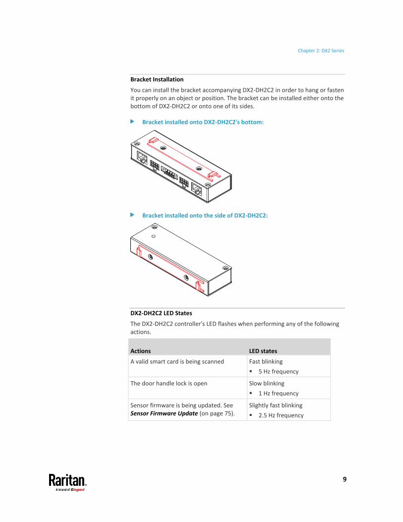
Bracket Installation
You can install the bracket accompanying DX2-DH2C2 in order to hang or fasten it properly on an object or position. The bracket can be installed either onto the bottom of DX2-DH2C2 or onto one of its sides.
Bracket installed onto DX2-DH2C2's bottom:
Bracket installed onto the side of DX2-DH2C2:
DX2-DH2C2 LED States
The DX2-DH2C2 controller's LED flashes when performing any of the following actions.
Actions LED states
A valid smart card is being scanned Fast blinking
▪ 5 Hz frequency
The door handle lock is open Slow blinking
▪ 1 Hz frequency
Sensor firmware is being updated. See Sensor Firmware Update (on page 75).
Slightly fast blinking
▪ 2.5 Hz frequency

Chapter 2: DX2 Series
10
DX2 Temperature and Humidity Sensors
There are four types of DX2 temperature and humidity sensor packages.
Package Package content
DX2-T1 Contain one DX2-T1 sensor package, which detects the temperature.
DX2-T1H1 Contain one DX2-T1H1 sensor package, which detects both the temperature and humidity.
DX2-T2H1 Contain the following:
• One DX2-T1H1 sensor package.
• One DX2-T1 sensor package.
DX2-T3H1 Contain the following:
• One DX2-T1H1 sensor package.
• Two DX2-T1 sensor packages.
The following diagram shows a DX2-T1 or DX2-T1H1 sensor package.
Number Component Function
Two RJ-45 ports Connect a standard network patch cable for either or both purposes below:
• Connect to the SENSOR port of a Raritan product (like a PX3 PDU) or Legrand PDU.
• Cascade DX2 sensor package(s).
See Cascading DX2 Sensor Packages (on page 17).
Status LED Indicate the sensor status. See DX2 LED States (on page 11).
Tip -- other generations of temperature and humidity sensors:
Raritan has developed 4 generations of humidity and temperature sensors. Choose the type that satisfies your needs. The newest generation is DX2 series.
Chapter 2: DX2 Series
11
For the other generations, see:
▪ DPX Temperature and Humidity Sensors (on page 50)
▪ DPX2 Temperature and Humidity Sensors (on page 43)
▪ DPX3 Temperature and Humidity Sensors (on page 39)
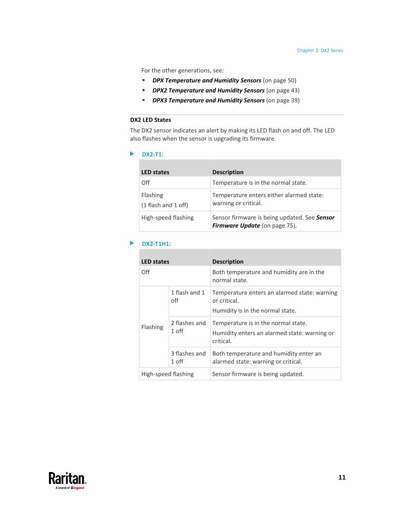
DX2 LED States
The DX2 sensor indicates an alert by making its LED flash on and off. The LED also flashes when the sensor is upgrading its firmware.
DX2-T1:
LED states Description
Off Temperature is in the normal state.
Flashing
(1 flash and 1 off)
Temperature enters either alarmed state: warning or critical.
High-speed flashing Sensor firmware is being updated. See Sensor Firmware Update (on page 75).
DX2-T1H1:
LED states Description
Off Both temperature and humidity are in the normal state.
Flashing
1 flash and 1 off
Temperature enters an alarmed state: warning or critical.
Humidity is in the normal state.
2 flashes and 1 off
Temperature is in the normal state.
Humidity enters an alarmed state: warning or critical.
3 flashes and 1 off
Both temperature and humidity enter an alarmed state: warning or critical.
High-speed flashing Sensor firmware is being updated.

Chapter 2: DX2 Series
12
DX2-CC2 Contact Closure Sensors
Raritan's contact closure sensor can detect the open-and-closed status of connected detectors/switches.
There are two channels for connecting two discrete detectors/switches (state: on/off).
Four termination points are available on this sensor: the two to the right are associated with one channel, and the two to the left are associated with the other.
Number Component Function
Two RJ-45 ports Connect a standard network patch cable for either or both purposes below:
• Connect to the SENSOR port of a Raritan product (like a PX3 PDU) or Legrand PDU.
• Cascade DX2 sensor package(s).
See Cascading DX2 Sensor Packages (on page 17).
Two pairs of termination points
Connect two discrete detectors/switches.
Two LEDs Indicate two channels' status.

Chapter 2: DX2 Series
13
Supported detector/switch types:
At a minimum, a discrete detector/switch is required for DX2-CC2 to work properly. The types of discrete detectors/switches that can be connected to DX2-CC2 include those for:
• Door open/closed detection
• Door lock detection
• Smoke detection
• Vibration detection
When using third-party probes, you must test them with DX2-CC2 to ensure they work properly.
Important: Integration and testing for third-party detectors/switches is the sole responsibility of the customer. Raritan cannot assume any liability as a result of improper termination or failure (incidental or consequential) of third-party detectors/switches that customers provide and install. Failure to follow installation and configuration instructions can result in false alarms or no alarms. Raritan makes no statement or claim that all third-party detectors/switches will work with Raritan's contact closure sensors.
To make DX2-CC2 work properly:
1. Connect 1 to 2 contact closure detectors/switches to DX2-CC2. See Connecting Detectors/Switches to DX2-CC2 (on page 14).
2. Connect DX2-CC2 to a Raritan or Legrand product that supports Raritan sensor packages, such as Raritan's PX3 or Legrand PDU.
3. Log in to the application of Raritan or Legrand product where DX2-CC2 is being connected, and configure Normally Open or Normally Closed for DX2-CC2.
▪ See Configuring DX2-CC2's Normal State (on page 16).

Chapter 2: DX2 Series
14
Connecting Detectors/Switches to DX2-CC2
DX2-CC2 comprises two parts: sensor box and terminal module. The terminal module is detachable so it is convenient to connect/disconnect discrete detectors/switches.
To make connections when the terminal module is attached:
1. Strip the insulation around 12 mm from the end of each wire of discrete detectors/switches.
2. Fully insert each wire of both detectors/switches into each termination point.
▪ Plug both wires of a detector/switch into the two termination points to the left.
▪ Plug both wires of the other detector/switch into the two termination points to the right.
3. Use a screwdriver with a 2.5 mm wide shaft to tighten the screws above each termination point to secure the wires, using a torque of 0.196 N·m (2 kgf·cm).

Chapter 2: DX2 Series
15
To make connections after the terminal module is separated:
You can also connect a detector/switch when the terminal module is separated from the sensor box.
1. Loosen the screws at two sides of the terminal module.
Note: The two screws are not removable so just loosen them.
2. Separate the terminal module from the sensor box.
3. After connecting detectors/switches to the terminal module, plug the terminal module back into the sensor box, and then tighten the screws at two sides of the terminal module.

Chapter 2: DX2 Series
16
Configuring DX2-CC2's Normal State
Before using DX2-CC2 for detection, select the normal state of DX2-CC2 via the software application of the Raritan or Legrand product where this DX2-CC2 is being connected.
To select the normal state of DX2-CC2:
1. Log in to the web interface of the Raritan or Legrand product where DX2-CC2 is being connected.
2. Do the following.
a. Click Peripherals > DX2-CC2's name > Edit Settings > Sensor Polarity.
b. Choose one of the normal state options.
Option Description
Normally Open Factory default.
▪ It is considered normal when the switch/detector connected to DX2-CC2 is open.
▪ When the switch/detector turns closed, an alarm is shown.
Normally Closed ▪ It is considered normal when the switch/detector connected to DX2-CC2 is closed.
▪ When the switch/detector turns open, an alarm is shown.
Alarm of DX2-CC2 is shown on the following:
• DX2-CC2 LED. See DX2-CC2 Contact Closure Sensor LEDs (on page 17).
• Software application of the Raritan or Legrand product where this DX2-CC2 is connected. For details, refer to the user guide or online help of your Raritan or Legrand product.

Chapter 2: DX2 Series
17
DX2-CC2 Contact Closure Sensor LEDs
LED description in this section applies to all of Raritan's contact closure sensors, including DPX-CC2-TR, DX series and DX2-CC2. See Available DX Sensor Packages (on page 20) and DPX Contact Closure Sensors (on page 54).
LEDs indicate states of detectors/switches connected to the contact closure sensor channels.
The LED is lit when the associated detector/switch enters the "alarmed" state. See Configuring DX2-CC2's Normal State (on page 16) for how to set the Normal state of DX2-CC2.
The meaning of a lit LED varies depending on the Normal state settings.
• When the Normal state is set to Normally Closed (N.C):
LED Sensor state
Off Closed
Lit Open
• When the Normal state is set to Normally Open (N.O):
LED Sensor state
Off Open
Lit Closed
Cascading DX2 Sensor Packages
To increase the number of connected DX2 sensor packages per SENSOR port, you can cascade DX2 using standard network patch cables (CAT5e or higher).
A maximum of 12 DX2 sensor packages can be daisy chained.
Tip: You can also make a sensor chain comprising DX2, DX and DPX3 sensor packages. See Cascading DX2, DX and DPX3 Sensor Packages (on page 65).
To cascade DX2 sensor packages:
1. Connect a standard network patch cable to either RJ-45 port of the first DX2 sensor package.
Exception: For a Raritan PDU or EMX with an "RJ-12" SENSOR port, an RJ-12 to RJ-45 adapter cable (part number: RJ12M-RJ45M) is needed, which you can request from Raritan.

Chapter 2: DX2 Series
18
2. If you want to cascade DX2 packages, get an additional standard network patch cable (CAT5e or higher) and then:
a. Plug one end of the cable into the remaining RJ-45 port on the prior DX2 package.
b. Plug the other end into either RJ-45 port on an additional DX2 package.
Repeat the same steps to cascade more DX2 packages.
Exception: You CANNOT cascade DX2-DH2C2 packages. For details, see DX2-DH2C2 Door Handle Controller (on page 6).
3. Make sure the total number of sensors and actuators connected to these DX2 packages does not exceed 32 per sensor port. See Supported Maximum Number of Sensors and Actuators (on page 73).
19
A DX sensor package consists of terminals, sensors and two RJ-45 ports.
Different DX sensor packages have a different number of terminals. Every pair of terminals is a channel for connecting a sensor or actuator.
DX contact closure channels do NOT support any water detection sensors, including Raritan's DPX water sensors -- DPX-WSF and DPX-WSC series.
DX contact closure channels support the following types of sensors:
• Door open/closed detection
• Door lock detection
• Smoke detection
• Vibration detection
Important: DX may also not support third-party leakage detectors so you must test them before using any third-party leakage detectors.
DX series works with Raritan's DPX3 sensor hub 'DPX3-ENVHUB4', but not with the DPX sensor hub 'DPX-ENVHUB4'.
No sensor cables are shipped with DX sensor packages.
With standard network patch cables (CAT5e or higher), you can:
• Connect a DX sensor to a Raritan or Legrand product with the RJ-45 SENSOR port, such as Raritan's PX3 PDU or Legrand PDU.
Exception: For a Raritan PDU or EMX with an "RJ-12" SENSOR port, an RJ-12 to RJ-45 adapter cable (part number: RJ12M-RJ45M) is needed, which you can request from Raritan.
• Daisy chain DX sensor packages.
Warning: Do NOT use a crossover cable for connection.
In This Chapter
Available DX Sensor Packages ............................................................................ 20 DX-D2C6 .............................................................................................................. 21 DX-PD2C5 ............................................................................................................ 24 DX-PIR ................................................................................................................. 26 DX-D4C3 .............................................................................................................. 29 DX-VBR ................................................................................................................ 32 Making Connections ........................................................................................... 33 Adjusting Dip Switches ....................................................................................... 37
Chapter 3 DX Series

Chapter 3: DX Series
20
Available DX Sensor Packages
Sensor packages Description
DX-D2C6 • 7 pairs of terminals:
▪ 2 for connecting dry contact signal actuators (DC).
▪ 5 for connecting contact closure sensors (CC).
• 1 hall effect sensor
Note: The hall effect sensor is reserved for future use and currently shall NOT be used.
See DX-D2C6 (on page 21).
DX-PD2C5 7 pairs of terminals:
• 2 for connecting powered dry contact signal actuators.
• 5 for connecting contact closure sensors.
See DX-PD2C5 (on page 24).
DX-PIR • 1 occupancy sensor
• 1 tamper sensor
• 1 pair of terminals for connecting contact closure sensors
See DX-PIR (on page 26).
DX-D4C3 7 pairs of terminals:
• 4 for connecting dry contact signal actuators (DC).
• 3 for connecting contact closure sensors (CC).
See DX-D4C3 (on page 29).
DX-VBR • 1 vibration sensor
• 1 pair of terminals for connecting contact closure sensors
See DX-VBR (on page 32).
For detailed information on sensor names, see Sensor Naming Conventions (on page 76).
Tip -- other generations of contact closure sensors:
There are several generations of Raritan contact closure sensors: DPX-CC2-TR, DX series and DX2 series. Choose the type that satisfies your needs.
Note that only DPX-CC2-TR supports Raritan's water sensors while DX and DX2 contact closure sensors do NOT support them.

Chapter 3: DX Series
21
For the other generations, see:
• DPX Contact Closure Sensors (on page 54)
• Available DX2 Sensor Packages (on page 5)
DX-D2C6
DX-D2C6 has seven channels for both contact closure sensors and dry contact signal actuators.
The label attached to DX-D2C6 helps you identify different channels.
DX-D2C6 Label:

Chapter 3: DX Series
22
• CC represents a contact closure sensor channel. There are five CC channels: CC1 through CC5.
• DC represents a dry contact signal actuator channel. There are two DC channels: DC1 and DC2.
DX-D2C6 hall effect sensor (reserved):
DX-D2C6 contains a built-in hall effect sensor, which can detect whether a door is open or closed. The hall effect sensor is reserved for future use and currently shall NOT be used. After connecting DX-D2C6 to a Raritan PDU or EMX, this built-in sensor will be detected and show up in that PDU or EMX web interface and SNMP MIB, which is normal.
DX-D2C6 terminals, dip switches, and LEDs:
Terminals, dip switches, and LEDs are located in two rows as shown below.
Numbers Components
CC and DC channels.
• Top row:
Four CC channels (CC2 - CC5).
Two DC channels (DC1 - DC2).
• Bottom row:
One CC channel (CC1).
See Connecting Detectors/Actuators to DX (on page 34) for how to connect CC sensors or DC actuators.
Dip switches for configuring the Normal state of each CC channel. See Adjusting Dip Switches (on page 37).
• Top row:
Dip switch 1 controls CC2.
Dip switch 2 controls CC3.

Chapter 3: DX Series
23
Numbers Components
Dip switch 3 controls CC4.
Dip switch 4 controls CC5.
• Bottom row:
Dip switch 1 controls CC1.
Dip switch 2 controls the built in hall effect sensor.
Tip: If an alert is shown for this hall effect sensor, you can disable it by turning on/off dip switch 2.
CC status LEDs. For details, see DX2-CC2 Contact Closure Sensor LEDs (on page 17).
High-speed flashing of CC1 LED indicates that the DX firmware upgrade is in progress. See Sensor Firmware Update (on page 75).
• Top row:
The four LEDs, from left to right, indicate the states of CC2, CC3, CC4 and CC5 respectively.
• Bottom row:
The LED indicates the CC1 state.

Chapter 3: DX Series
24
DX-PD2C5
DX-PD2C5 is physically similar to DX-D2C6 except for the following differences:
• Dry contact signal channels of DX-PD2C5 supply DC 12V power to the connected actuators.
• Dry contact signal channels of DX-PD2C5 only support the connection of EMKA (1150-U5x) door handles.
• DX-PD2C5 works with PX3 PDUs, PX3TS transfer switches and Legrand PDUs only.
• DX-PD2C5 supports a maximum cabling length of 29 feet (9 meters) instead of 98 feet (30 meters). For details, see Supported Maximum Sensor Distance (on page 71).
• No asset management strips can be connected simultaneously.
Warning: If high security is required, it is strongly recommended that DX-PD2C5 shall NOT be used.
A label is attached to DX-PD2C5 to help you identify different channels.
DX-PD2C5 Label:
• CC represents a contact closure sensor channel. There are five CC channels: CC1 through CC5.
• PDC represents a dry contact signal actuator channel which is powered. There are two PDC channels: PDC1 and PDC2. Note that each PDC channel has two electrical polarity markings below it: - (negative) and + (positive), which you must follow when connecting an EMKA door handle.
Chapter 3: DX Series
25
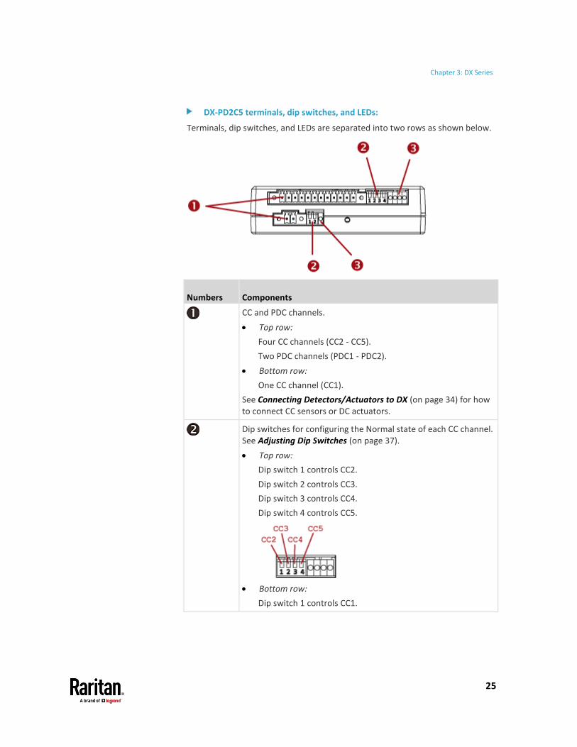
DX-PD2C5 terminals, dip switches, and LEDs:
Terminals, dip switches, and LEDs are separated into two rows as shown below.
Numbers Components
CC and PDC channels.
• Top row:
Four CC channels (CC2 - CC5).
Two PDC channels (PDC1 - PDC2).
• Bottom row:
One CC channel (CC1).
See Connecting Detectors/Actuators to DX (on page 34) for how to connect CC sensors or DC actuators.
Dip switches for configuring the Normal state of each CC channel. See Adjusting Dip Switches (on page 37).
• Top row:
Dip switch 1 controls CC2.
Dip switch 2 controls CC3.
Dip switch 3 controls CC4.
Dip switch 4 controls CC5.
• Bottom row:
Dip switch 1 controls CC1.

Chapter 3: DX Series
26
Numbers Components
Note: Dip switch 2 in the bottom row does not control any channel and can be ignored.
CC status LEDs. For details, see DX2-CC2 Contact Closure Sensor LEDs (on page 17).
High-speed flashing of CC1 LED indicates that the DX firmware upgrade is in progress. See Sensor Firmware Update (on page 75).
• Top row:
The four LEDs, from left to right, indicate the states of CC2, CC3, CC4 and CC5 respectively.
• Bottom row:
The LED indicates the CC1 state.
DX-PIR
DX-PIR contains one occupancy sensor (that is, presence detector), one tamper sensor and a pair of terminals for connecting a contact closure (CC) sensor.

Chapter 3: DX Series
27
Occupancy sensor:
The occupancy sensor is located on the top of the DX-PIR. It uses the passive infrared technology to detect the motion of a person by sensing the temperature differences between a person and the surroundings.
The diagrams below show the occupancy sensor's detection range and sensing area.

Chapter 3: DX Series
28
Side View Top View
▪ Maximum range: 5 meters
▪ Vertical sensing area: 82 degrees
(+/- 41 degrees)
▪ Maximum range: 5 meters
▪ Horizontal sensing area: 94 degrees
(+/- 47 degrees)
Conditions for the detected target:
• Temperature difference between the target and the surroundings should exceed 4 degrees Celsius (7.2 degrees Fahrenheit).
• Target's movement speed: 1.0 m/s.
• Target concept is human body (size: 700 x 250 mm).
Tamper sensor:
The tamper sensor is located on the back of the DX-PIR. This sensor is used to detect whether the DX-PIR is moved away from its original position. In the normal state, the DX-PIR is firmly affixed to an object so this sensor, which is a button on the back of DX-PIR, is pressed down. If someone takes the DX-PIR away, the button springs up so the sensor is in the alarmed state.

Chapter 3: DX Series
29
DX-PIR Terminals, dip switches and LED:
Numbers Components
One CC channel comprising a pair of terminals.
See Connecting Detectors/Actuators to DX (on page 34) for how to connect a CC sensor.
▪ Dip switch 1 configures the Normal state of the CC channel.
▪ Dip switch 2 controls the built-in occupancy sensor.
See Adjusting Dip Switches (on page 37).
CC status LED. For details, see DX2-CC2 Contact Closure Sensor LEDs (on page 17).
High-speed flashing of CC1 LED indicates that the DX firmware upgrade is in progress. See Sensor Firmware Update (on page 75).
DX-D4C3
DX-D4C3 contains four channels for dry contact signal actuators and three channels for contact closure sensors.

Chapter 3: DX Series
30
The label attached to DX-D4C3 helps you identify each channel.
DX-D4C3 Label:
• CC represents a contact closure sensor channel. There are three CC channels: CC1 through CC3.
• DC represents a dry contact signal actuator channel. There are four DC channels: DC1 through DC4.
DX-D4C3 terminals, dip switches, and LEDs:
Terminals, dip switches, and LEDs are located in two rows as shown below.
Numbers Components
CC and DC channels.
• Top row:
2 CC channels (CC2 - CC3).
4 DC channels (DC1 - DC4).
• Bottom row:
One CC channel (CC1).
See Connecting Detectors/Actuators to DX (on page 34) for how to connect CC sensors or DC actuators.
Dip switches for configuring the Normal state of each CC channel. See Adjusting Dip Switches (on page 37).
• Top row:
Dip switch 1 controls CC2.
Dip switch 2 controls CC3.

Chapter 3: DX Series
31
Numbers Components
• Bottom row:
Dip switch 1 controls CC1.
Note: Dip switches 3 and 4 in the top row and dip switch 2 in the bottom row do not control any channel and can be ignored.
CC status LEDs. For details, see DX2-CC2 Contact Closure Sensor LEDs (on page 17).
High-speed flashing of CC1 LED indicates that the DX firmware upgrade is in progress. See Sensor Firmware Update (on page 75).
• Top row:
The two leftmost LEDs, from left to right, indicate the states of CC2 and CC3 respectively.
Note: The two rightmost LEDs in the top row are not associated with any CC channels and can be ignored.
• Bottom row:
The LED indicates the CC1 state.

Chapter 3: DX Series
32
DX-VBR
DX-VBR contains one vibration sensor and a pair of terminals for connecting a contact closure (CC) sensor.
Vibration sensor:
The built-in vibration sensor detects the vibration of any object where DX-VBR is affixed. The sensor determines the vibration by measuring the accelerations in three mutually perpendicular directions, and then generating a numeric value representing the magnitude of the acceleration due to gravity of the Earth. Below is the calculation formula.
a = (ax2 + ay
2 + az2)1/2
• The acceleration has two measurement units: g and milli-g.
▪ 1 g = 9.80665 m/s2
▪ 1 milli-g = 0.001 g
• "a" in the above formula denotes the magnitude of the acceleration.
▪ 0 <= a <= 3.464 g
Note: <= means "less than" or "equal to."
• ax, ay and az represent the accelerations in three mutually perpendicular directions x, y and z.
▪ x, y and z form a Cartesian coordinate system.
▪ -2 g <= ax <= 2 g
▪ -2 g <= ay <= 2 g
▪ -2 g <= az <= 2 g

Chapter 3: DX Series
33
DX-VBR Terminals, dip switches and LED:
Numbers Components
One CC channel comprising a pair of terminals.
See Connecting Detectors/Actuators to DX (on page 34) for how to connect a CC sensor.
▪ Dip switch 1 configures the Normal state of the CC channel.
▪ Dip switch 2 does not control any CC channel and can be ignored.
See Adjusting Dip Switches (on page 37).
CC status LED. For details, see DX2-CC2 Contact Closure Sensor LEDs (on page 17).
High-speed flashing of CC1 LED indicates that the DX firmware upgrade is in progress. See Sensor Firmware Update (on page 75).
Making Connections
Pre-installed DX Brackets
To allow you to hang or affix a DX onto an object or position, two brackets have been installed on the rear side of a DX sensor package when shipped out of the factory.
Below is the diagram of a DX sensor package with two brackets installed.

Chapter 3: DX Series
34
Connecting Detectors/Actuators to DX
A DX sensor package comprises two parts: a sensor box and the terminal module(s). A terminal module is removable.
Note: The following diagrams illustrate a terminal module comprising two termination points only. Your DX terminal module may be larger if it has more terminals.
To make connections when the terminal module is attached:
1. Strip the insulation around 12 mm from the end of each wire of a detector or actuator.
▪ Wire size range: AWG 28 to 20 or 0.09 to 0.5 mm2
2. Fully insert each wire into each termination point of a CC, DC or PDC channel on the DX sensor package.
Important: For a PDC channel, you must check the electrical polarity markings (+ and -) on the DX label to make sure each wire is inserted into the correct termination point with the correct polarity.
3. Use a screwdriver with a 2.5 mm wide shaft to tighten the screws above each termination point to secure the wires, using a torque of 0.196 N·m (2 kgf·cm).

Chapter 3: DX Series
35
To make connections after the terminal module is detached:
1. Loosen the screws at two sides of the terminal module.
Note: The two screws are not removable so just loosen them.
2. Separate the terminal module from the sensor box.
3. After connecting detectors/switches to the terminal module, plug the terminal module back into the sensor box, and then tighten the screws at two sides of the terminal module.

Chapter 3: DX Series
36
Cascading DX Sensor Packages
To increase the number of connected DX sensor packages per SENSOR port, you can cascade DX using standard network patch cables (CAT5e or higher). A maximum of 12 DX sensor packages can be daisy chained.
Tip: You can also make a sensor chain comprising DX2, DX and DPX3 sensor packages. See Cascading DX2, DX and DPX3 Sensor Packages (on page 65).
Numbers Components
RJ-45 ports, each of which is located on either end of a DX sensor package.
RJ-12 port, which is reserved for future use and is hidden now.
To cascade DX sensor packages:
1. Connect a standard network patch cable to either RJ-45 port of the first DX sensor package.
Exception: For a Raritan PDU or EMX with an "RJ-12" SENSOR port, an RJ-12 to RJ-45 adapter cable (part number: RJ12M-RJ45M) is needed, which you can request from Raritan.
2. If you want to cascade DX packages, get an additional standard network patch cable (CAT5e or higher) and then:
a. Plug one end of the cable into the remaining RJ-45 port on the prior DX package.
b. Plug the other end into either RJ-45 port on an additional DX package.
Repeat the same steps to cascade more DX packages.

Chapter 3: DX Series
37
Exception: You CANNOT cascade DX-PD2C5 sensor packages. For details, see DX-PD2C5 (on page 24).
3. Make sure the total number of sensors and actuators connected to these DX packages does not exceed 32 per sensor port. See Supported Maximum Number of Sensors and Actuators (on page 73).
Adjusting Dip Switches
There are two Normal settings for each CC channel on DX packages.
• N.O (Normally Open): The open status of the connected detector/switch is considered normal. An alarm is triggered when the detector/switch turns closed.
• N.C (Normally Closed): The closed status of the connected detector/switch is considered normal. An alarm is triggered when the detector/switch turns opened.
Each CC channel and the DX-PIR occupancy sensor's Normal setting is configured by turning on or off its corresponding dip switch.
To adjust dip switches for CC channels:
• N.O: Turn ON the dip switch by pressing it down.
• N.C: Turn OFF the dip switch by pushing (or keeping) it up.
To adjust the dip switch for DX-PIR occupancy sensor:
• Turn it OFF (up) when human absence is considered the normal state.
• Turn it ON (down) when human presence is considered the normal state.

38
A DPX3 sensor package features the following:
• Its connection interface is RJ-45.
• You can cascade a maximum of 12 DPX3 sensor packages.
DPX3 series works with Raritan's DPX3 sensor hub 'DPX3-ENVHUB4', but not with the DPX sensor hub 'DPX-ENVHUB4'.
With a standard network patch cable (CAT5e or higher), you can:
• Connect a DPX3 sensor to a Raritan or Legrand product with the "RJ-45" SENSOR port, such as Raritan's PX3 PDU or Legrand PDU.
Exception: For a Raritan PDU or EMX with an "RJ-12" SENSOR port, an RJ-12 to RJ-45 adapter cable (part number: RJ12M-RJ45M) is needed, which you can request from Raritan.
• Daisy chain DPX3 sensor packages.
Warning: Do NOT use a crossover cable for connection.
In This Chapter
Available DPX3 Sensor Packages ........................................................................ 38 DPX3 Temperature and Humidity Sensors ......................................................... 39 Cascading DPX3 Sensor Packages ....................................................................... 40
Available DPX3 Sensor Packages
Sensor packages Description
DPX3-T1H1 • 1 temperature sensor
• 1 humidity sensor
See DPX3 Temperature and Humidity Sensors (on page 39).
For detailed information on sensor names, see Sensor Naming Conventions (on page 76).
Chapter 4 DPX3 Series

Chapter 4: DPX3 Series
39
DPX3 Temperature and Humidity Sensors
DPX3-T1H1 is used to detect the environmental temperature and humidity.
Number Component Function
Two RJ-45 ports Connect a standard network patch cable for either or both purposes below:
▪ Connect to the SENSOR port of a Raritan product (like a PX3 PDU) or Legrand PDU.
▪ Cascading DPX3 sensor packages.
See Cascading DPX3 Sensor Packages (on page 40).
LED Indicate the sensor status. See DPX3 LED States (on page 39).
Tip -- other generations of temperature and humidity sensors:
Raritan has developed 4 generations of humidity and temperature sensors. Choose the type that satisfies your needs. The newest generation is DX2 series.
For the other generations, see:
▪ DPX Temperature and Humidity Sensors (on page 50)
▪ DPX2 Temperature and Humidity Sensors (on page 43)
▪ DX2 Temperature and Humidity Sensors (on page 10)
DPX3 LED States
The DPX3 sensor indicates an alert by making its LED flash on and off. The LED also flashes when the sensor is upgrading its firmware.
DPX3-T1H1:
LED states Description
Off Both temperature and humidity are in the normal state.

Chapter 4: DPX3 Series
40
LED states Description
Flashing
1 flash and 1 off
Temperature enters an alarmed state: warning or critical.
Humidity is in the normal state.
2 flashes and 1 off
Temperature is in the normal state.
Humidity enters an alarmed state: warning or critical.
3 flashes and 1 off
Both temperature and humidity enter an alarmed state: warning or critical.
High-speed flashing Sensor firmware is being updated.
Cascading DPX3 Sensor Packages
To increase the number of connected DPX3 sensor packages per SENSOR port, you can cascade DPX3 using standard network patch cables (CAT5e or higher). Up to 12 DPX3 sensor packages can be daisy chained.
Tip: You can also make a sensor chain comprising DX2, DX and DPX3 sensor packages. See Cascading DX2, DX and DPX3 Sensor Packages (on page 65).
To cascade DPX3 sensor packages:
1. Connect a standard network patch cable to either RJ-45 port of the first DPX3 sensor package.
Note: For a Raritan EMX or PDU with the "RJ-12" SENSOR port, use the RJ-12 to RJ-45 adapter cable instead.
2. If you want to cascade DPX3 sensor packages, get an additional standard network patch cable (CAT5e or higher) and then:
a. Plug one end of the cable into the remaining RJ-45 port on the prior DPX3.
b. Plug the other end into either RJ-45 port on an additional DPX3.

Chapter 4: DPX3 Series
41
Repeat the same steps to cascade more DPX3 sensor packages.
3. Make sure the total number of cascaded sensors does not exceed 32 per sensor port. See Supported Maximum Number of Sensors and Actuators (on page 73).

42
DPX2 sensors are physically similar to DPX sensors. Below are their differences:
• DPX2 does not have a factory-installed sensor cable so you must manually connect DPX2 sensors to a DPX2 sensor cable.
• DPX2 has an LED to show the sensor status.
• DPX2 provides the chain position information.
• Individual DPX2 sensors can be replaced without the need to re-connect the DPX2 sensor cable.
• DPX2 series works with Raritan's DPX3 sensor hub 'DPX3-ENVHUB4', but not with the DPX sensor hub 'DPX-ENVHUB4'.
• DPX2 can be connected to the end of a DX2, DX, or DPX3 sensor chain while DPX sensor packages CANNOT. For details, see Connecting a DPX2 Sensor Package to DX2, DX or DPX3 (on page 47).
In This Chapter
Available DPX2 Sensor Packages ........................................................................ 43 DPX2 Temperature and Humidity Sensors ......................................................... 43 Connection and Disconnection ........................................................................... 44 Connecting a DPX2 Sensor Package to DX2, DX or DPX3.................................... 47
Chapter 5 DPX2 Series
Chapter 5: DPX2 Series
43
Available DPX2 Sensor Packages
Sensor packages Description
DPX2-T1 • 1 temperature sensor
See DPX2 Temperature and Humidity Sensors (on page 43).
DPX2-T1H1 • 1 temperature sensor
• 1 humidity sensor
See DPX2 Temperature and Humidity Sensors (on page 43).
DPX2-T2H1 • 2 temperature sensors
• 1 humidity sensor
See DPX2 Temperature and Humidity Sensors (on page 43).
DPX2-T3H1 • 3 temperature sensors
• 1 humidity sensor
See DPX2 Temperature and Humidity Sensors (on page 43).
For detailed information on sensor names, see Sensor Naming Conventions (on page 76).
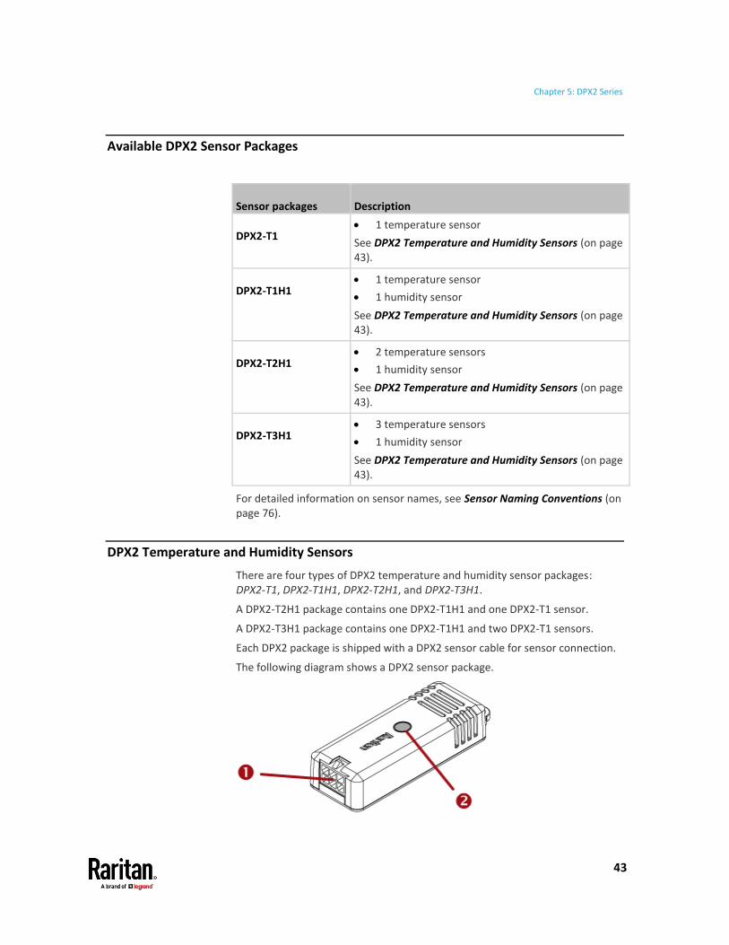
DPX2 Temperature and Humidity Sensors
There are four types of DPX2 temperature and humidity sensor packages: DPX2-T1, DPX2-T1H1, DPX2-T2H1, and DPX2-T3H1.
A DPX2-T2H1 package contains one DPX2-T1H1 and one DPX2-T1 sensor.
A DPX2-T3H1 package contains one DPX2-T1H1 and two DPX2-T1 sensors.
Each DPX2 package is shipped with a DPX2 sensor cable for sensor connection.
The following diagram shows a DPX2 sensor package.

Chapter 5: DPX2 Series
44
Number Component Function
Head connector Connect to the DPX2 sensor cable.
LED Indicate the sensor status.
These LEDs are functionally identical to DX2 LED States (on page 11).
Tip -- other generations of temperature and humidity sensors:
Raritan has developed 4 generations of humidity and temperature sensors. Choose the type that satisfies your needs. The newest generation is DX2 series.
For the other generations, see:
▪ DPX Temperature and Humidity Sensors (on page 50)
▪ DPX3 Temperature and Humidity Sensors (on page 39)
▪ DX2 Temperature and Humidity Sensors (on page 10)
Connection and Disconnection
Before connecting a DPX2 sensor to a Raritan or Legrand product, you must connect it to a DPX2 sensor cable first.
If any connected sensor is broken, you can replace it with a new one without disconnecting the DPX2 sensor cable from the Raritan or Legrand product.
To connect the DPX2 sensor package to the end of a DX sensor chain, see Connecting a DPX2 Sensor Package to DX2, DX or DPX3 (on page 47).
Connecting a DPX2 Sensor Cable
Raritan has three types of DPX2 sensor cables. The difference is the number of available head connectors on the cable: one to three head connectors.
DPX2 sensor cables cannot be daisy chained.
The following diagram illustrates a DPX2 sensor cable with three head connectors.

Chapter 5: DPX2 Series
45
Number Component Function
RJ-12 connector Connect to a Raritan PDU or EMX.
Head connectors Connect DPX2 sensors.
Sensor connection guidelines:
Always make sure there are NO free head connectors between the sensor cable's RJ-12 connector and the final DPX2 sensor attached to it. That is, each head connector prior to the final DPX2 sensor must be occupied with a sensor. Otherwise, those sensors following the "free" head connector(s) on the same sensor cable do not work properly.
Below illustrates the scenarios when the number of DPX2 sensors is less than the number of head connectors on a DPX2 sensor cable.
• Scenario A: When only one sensor is connected, always connect it to the first head connector.
• Scenario B: When only two sensors are connected, always connect them to the first two head connectors.

Chapter 5: DPX2 Series
46
Disconnecting a DPX2 Sensor
You can remove any individual DPX2 sensor from the sensor cable whenever needed.
To disconnect a DPX2 sensor:
1. Press the latch of the cable connector so that the other side of the latch slightly goes up.
2. Pull the sensor away.
3. Connect any DPX2 sensor back to this free head connector, or move all subsequent DPX2 sensors that follow it on the same sensor cable to prior head connectors.
Warning: The final step is required, or all subsequent DPX2 sensors no longer work properly. For example, after removing the sensor from the 2nd head connector, you must either add a DPX2 sensor back to the 2nd head connector, or move the sensor attached to the 3rd head connector to the 2nd head connector.
Chapter 5: DPX2 Series
47
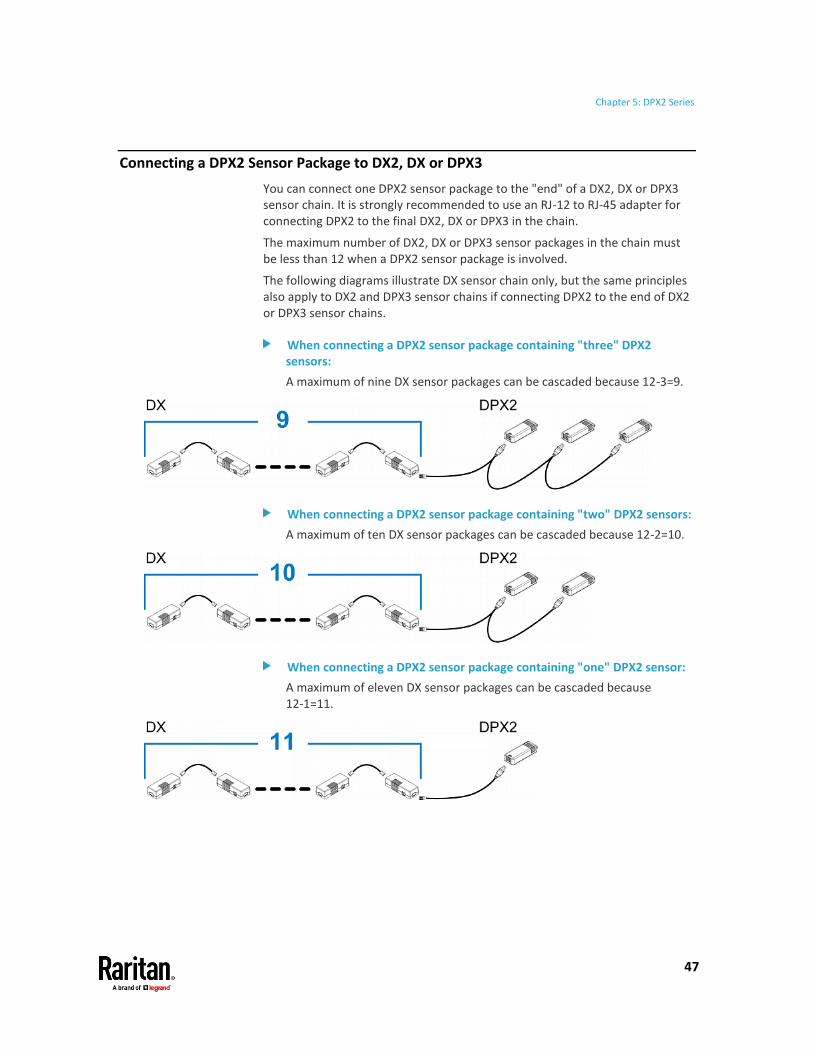
Connecting a DPX2 Sensor Package to DX2, DX or DPX3
You can connect one DPX2 sensor package to the "end" of a DX2, DX or DPX3 sensor chain. It is strongly recommended to use an RJ-12 to RJ-45 adapter for connecting DPX2 to the final DX2, DX or DPX3 in the chain.
The maximum number of DX2, DX or DPX3 sensor packages in the chain must be less than 12 when a DPX2 sensor package is involved.
The following diagrams illustrate DX sensor chain only, but the same principles also apply to DX2 and DPX3 sensor chains if connecting DPX2 to the end of DX2 or DPX3 sensor chains.
When connecting a DPX2 sensor package containing "three" DPX2 sensors:
A maximum of nine DX sensor packages can be cascaded because 12-3=9.
When connecting a DPX2 sensor package containing "two" DPX2 sensors:
A maximum of ten DX sensor packages can be cascaded because 12-2=10.
When connecting a DPX2 sensor package containing "one" DPX2 sensor:
A maximum of eleven DX sensor packages can be cascaded because 12-1=11.

48
DPX is the first generation of Raritan environmental sensor packages. Most DPX packages come with a factory-installed sensor cable with an "RJ-12" connector.
DPX supports the use of a Raritan sensor hub to increase the number of connected DPX sensors.
In This Chapter
Available DPX Sensor Packages .......................................................................... 49 DPX Temperature and Humidity Sensors ........................................................... 50 DPX Air Flow Sensors .......................................................................................... 51 DPX Differential Air Pressure Sensors ................................................................. 52 DPX Contact Closure Sensors .............................................................................. 54 DPX Floor Water Sensors .................................................................................... 60
Chapter 6 DPX Series

Chapter 6: DPX Series
49
Available DPX Sensor Packages
Sensor packages Description
DPX-T1 • 1 temperature sensor
See DPX Temperature and Humidity Sensors (on page 50).
DPX-T1H1 • 1 temperature sensor
• 1 humidity sensor
See DPX Temperature and Humidity Sensors (on page 50).
DPX-T3H1 • 3 temperature sensors
• 1 humidity sensor
See DPX Temperature and Humidity Sensors (on page 50).
DPX-AF1 • 1 air flow sensor
See DPX Air Flow Sensors (on page 51).
DPX-T1DP1 • 1 temperature sensor
• 1 differential air pressure sensor
See DPX Differential Air Pressure Sensors (on page 52).
DPX-CC2-TR • Two-channel contact closure sensors
See DPX Contact Closure Sensors (on page 54).
DPX-WSF • 1 floor-mounted water sensor
See Floor-mounted Water Sensor (on page 60).
DPX-WSC series • 1 cable water sensor
See Cable Water Sensor (on page 62).
For detailed information on sensor names, see Sensor Naming Conventions (on page 76).

Chapter 6: DPX Series
50
DPX Temperature and Humidity Sensors
Raritan provides three types of DPX temperature and humidity sensor packages: DPX-T1, DPX-T1H1 and DPX-T3H1.
A DPX-T3H1 package contains one DPX-T1H1 and two DPX-T1 sensors. As shown in the following diagram, all sensors have been connected to the sensor cable, when shipping out of the factory, in a manner that you cannot remove or replace any individual sensor.
Tip -- other generations of temperature and humidity sensors:
Raritan has developed 4 generations of humidity and temperature sensors. Choose the type that satisfies your needs. The newest generation is DX2 series.
For the other generations, see:
▪ DPX2 Temperature and Humidity Sensors (on page 43)
▪ DPX3 Temperature and Humidity Sensors (on page 39)
▪ DX2 Temperature and Humidity Sensors (on page 10)

Chapter 6: DPX Series
51
DPX Air Flow Sensors
If a DPX air flow sensor (DPX-AF1) is connected, make sure the sensor faces the source of the wind (such as a fan) in the appropriate orientation as indicated by the arrow on that sensor.
To affix this sensor to an object or place, screw it on using the sensor's two screw holes.
Disconnecting DPX-AF1:
Disconnecting only the head of the DPX-AF1 is not supported. Readings will continue and will be inaccurate. Disconnect the entire sensor if needed for maintenance.

Chapter 6: DPX Series
52
DPX Differential Air Pressure Sensors
The DPX differential air pressure sensor (DPX-T1DP1) detects not only the differential air pressure but also the temperature because it has a built-in temperature sensor.
This sensor is designed to receive the inputs of two pressure levels. Differential air pressure is measured by reading the difference of the two inputs.
Number Component Description
'In' port
(RJ-12)
Connect to a Raritan or Legrand product.
If cascading multiple air pressure sensors, connect this port to the 'Out' port of another sensor.
'Out' port
(RJ-12)
Use this port for cascading air pressure sensors.
'Lo' pressure nozzle
Receive low air pressure inputs.
'Hi' pressure nozzle
Receive high air pressure inputs.

Chapter 6: DPX Series
53
Connecting Tubes
Two tubes are shipped with the sensor. Connect the tubes to the sensor to receive two air pressure inputs. If necessary, cut the tubes so that the tube length meets your needs.
To install tubes:
1. Connect the tubes to both pressure nozzles of the sensor.
2. Place each tube's grommet in an appropriate location where you want to detect differential air pressure levels.
▪ Place the "Lo" tube's grommet in a low air pressure position.
▪ Place the "Hi" tube's grommet in a high air pressure position.
Connecting a DPX Sensor Package to an Air Pressure Sensor
You can add any DPX sensor package to a differential air pressure sensor.
To connect one DPX to one air pressure sensor:
1. Use a Raritan-provided phone cable to connect an air pressure sensor to a Raritan or Legrand product.
a. Plug one end of the cable into the sensor's "In" port.
b. Plug the other end into a Raritan or Legrand product's sensor port.
▪ An RJ-12 to RJ-45 adapter is required if your Raritan PDU has an RJ-45 SENSOR port, such as PX3.
2. Connect one DPX sensor package to the air pressure sensor's "Out" port.

Chapter 6: DPX Series
54
▪ It can be any available DPX sensor package shown in the section titled Available DPX Sensor Packages (on page 49).
Note: You CANNOT cascade more than two sensor packages in this DPX sensor chain.
DPX Contact Closure Sensors
Raritan's contact closure sensor (DPX-CC2-TR) can detect the open-and-closed status of connected detectors/switches.
This sensor has two channels for connecting two discrete (on/off) detectors/switches.
Four termination points are available: the two to the right are associated with one channel (as indicated by the sensor's LED number), and the two to the left are associated with the other.
Number Component
Two LEDs for indicating two channels' status.
Four termination points for connecting two discrete detectors/switches.
Chapter 6: DPX Series
55
Supported detector/switch types:
At a minimum, a discrete detector/switch is required in order for DPX-CC2-TR to work properly. The types of discrete detectors/switches that can be connected to DPX-CC2-TR include those for:
• Door open/closed detection
• Door lock detection
• Smoke detection
• Vibration detection
However, Raritan produces floor water sensors, which can be connected to and work with DPX-CC2-TR. See DPX Floor Water Sensors (on page 60).
When using third-party probes, you must test them with DPX-CC2-TR to ensure they work properly.
Important: Integration and testing for third-party detectors/switches is the sole responsibility of the customer. Raritan cannot assume any liability as a result of improper termination or failure (incidental or consequential) of third-party detectors/switches that customers provide and install. Failure to follow installation and configuration instructions can result in false alarms or no alarms. Raritan makes no statement or claim that all third-party detectors/switches will work with Raritan's contact closure sensors.
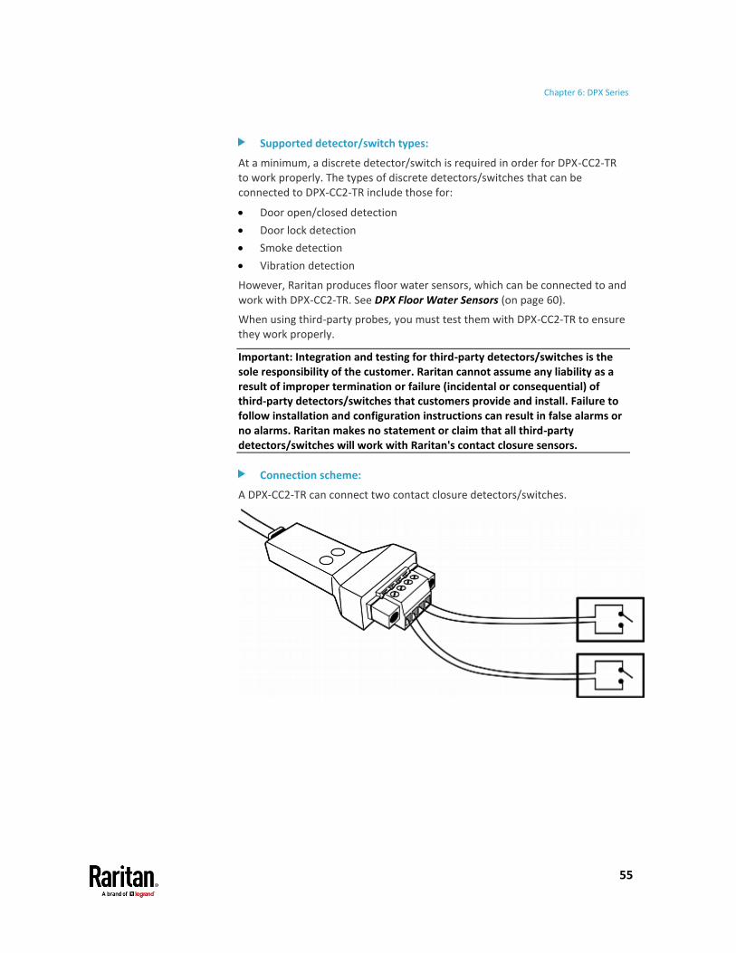
Connection scheme:
A DPX-CC2-TR can connect two contact closure detectors/switches.

Chapter 6: DPX Series
56
For details on connecting a detector/switch, see Connecting Detectors/Switches to DPX-CC2-TR (on page 56).
Tip -- other generations of contact closure sensors:
There are several generations of Raritan contact closure sensors: DPX-CC2-TR, DX series and DX2 series. Choose the type that satisfies your needs.
Note that only DPX-CC2-TR supports Raritan's water sensors while DX and DX2 contact closure sensors do NOT support them.
For the other generations, see:
• Available DX Sensor Packages (on page 20)
• Available DX2 Sensor Packages (on page 5)
Connecting Detectors/Switches to DPX-CC2-TR
DPX-CC2-TR comprises two parts: sensor box and terminal module. The terminal module is detachable so it is convenient to connect/disconnect discrete detectors/switches.
Below are the resistance values for DPX-CC2-TR to open and close a connected detector/switch reliably.
• Open: Greater than 320K ohm
• Closed: Less than 200K ohm
To make connections when the terminal module is attached:
1. Strip the insulation around 12 mm from the end of each wire of discrete detectors/switches.
2. Fully insert each wire of both detectors/switches into each termination point.
▪ Plug both wires of a detector/switch into the two termination points to the left.
▪ Plug both wires of the other detector/switch into the two termination points to the right.

Chapter 6: DPX Series
57
3. Use a screwdriver with a 2.5 mm wide shaft to tighten the screws above each termination point to secure the wires, using a torque of 0.196 N·m (2 kgf·cm).
To make connections after the terminal module is separated:
You can also connect a detector/switch when the terminal module is separated from the sensor box.
1. Loosen the screws at two sides of the terminal module.
Note: The two screws are not removable so just loosen them.
2. Separate the terminal module from the sensor box.

Chapter 6: DPX Series
58
3. After connecting detectors/switches to the terminal module, plug the terminal module back into the sensor box, and then tighten the screws at two sides of the terminal module.
Configuring a DPX Contact Closure Sensor
Before using DPX-CC2-TR to detect contact closure status, water, smoke or vibration, you must determine the normal state by adjusting its dip switch. The dip switch controls the LED state on DPX-CC2-TR, and is associated with a channel.
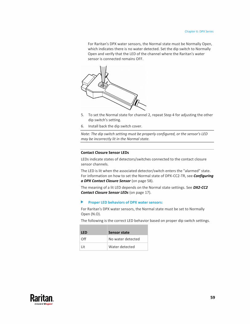
To adjust the dip switch setting:
1. Place the detectors/switches connected to DPX-CC2-TR to the position where you want to detect a specific environmental situation.
2. Uncover the dip switch on DPX-CC2-TR.
3. To set the Normal state for channel 1, locate the dip switch labeled 1.
4. Use a pointed tip such as a pen to set the slide switch to the position labeled N.O or N.C.
▪ N.O (Normally Open): The open status of the connected detector/switch is considered normal. An alarm is triggered when the detector/switch turns closed.
▪ N.C (Normally Closed): The closed status of the connected detector/switch is considered normal. An alarm is triggered when the detector/switch turns opened.
Chapter 6: DPX Series
59
For Raritan's DPX water sensors, the Normal state must be Normally Open, which indicates there is no water detected. Set the dip switch to Normally Open and verify that the LED of the channel where the Raritan's water sensor is connected remains OFF.
5. To set the Normal state for channel 2, repeat Step 4 for adjusting the other dip switch's setting.
6. Install back the dip switch cover.
Note: The dip switch setting must be properly configured, or the sensor's LED may be incorrectly lit in the Normal state.
Contact Closure Sensor LEDs
LEDs indicate states of detectors/switches connected to the contact closure sensor channels.
The LED is lit when the associated detector/switch enters the "alarmed" state. For information on how to set the Normal state of DPX-CC2-TR, see Configuring a DPX Contact Closure Sensor (on page 58).
The meaning of a lit LED depends on the Normal state settings. See DX2-CC2 Contact Closure Sensor LEDs (on page 17).
Proper LED behaviors of DPX water sensors:
For Raritan's DPX water sensors, the Normal state must be set to Normally Open (N.O).
The following is the correct LED behavior based on proper dip switch settings.
LED Sensor state
Off No water detected
Lit Water detected

Chapter 6: DPX Series
60
DPX Floor Water Sensors
Raritan has two types of DPX floor water sensors that work in conjunction with Raritan's DPX contact closure sensors -- DPX-CC2-TR.
• Floor-mounted water sensor (DPX-WSF)
• Cable water sensor (DPX-WSC series)
Note that only the DPX-CC2-TR support these water sensors. Other Raritan contact closure sensor packages do not support them.
Note: If you order a Raritan DPX water sensor with the part number containing the suffix -KIT, you get the DPX-CC2-TR, which supports it.
Floor-mounted Water Sensor
The floor-mounted water sensor (DPX-WSF) has a flat bottom so it can stand on the ground. The water detector's dimension is 63.5 mm x 13.25 mm x 13.2 mm (W x L x D).
Use one of the following methods to affix this detector to the ground:
• Screw the detector to the ground with your own screws. To avoid breaking the detector's enclosure, do not over tighten the screws.
• Put something weighing around 100 to 250 grams (0.22 to 0.55 pounds) into the empty bag shipped with this water sensor. Then use cable ties to wrap the bag right above the detector. Make sure the detector is not tilted so that its bottom evenly contacts the ground.
Number Item
Water detector.

Chapter 6: DPX Series
61
Number Item
Wires to connect to the contact closure sensor.
You need a minimum of 30 cm wires to prevent the contact closure sensor from being damaged by floor water (if any). Below are the wire length limitations:
• Minimum: 30 cm (11.8 inches)
• Maximum: 150 cm (59 inches)
How a Floor-mounted Water Sensor Works
The floor-mounted water sensor uses two poles marked with red arrows below to detect the water.
When there is some water between the two poles, it causes current loop back on the water sensor to trigger the alarm.

Chapter 6: DPX Series
62
Cable Water Sensor
The cable water sensor is in the shape of a cable so it can be flexibly placed, twisted or wrapped around a location where water may drip, such as a ceiling tile, water pipe or the floor.
Raritan provides two types of cable water sensors. The only difference is their cable length.
• DPX-WSC-35: 3.5 meters (11.5 feet).
• DPX-WSC-70: 7 meters (23 feet).
Number Item
Cable-shaped water detector.
Wires to connect to the contact closure sensor.
You need a minimum of 30 cm wires to prevent the contact closure sensor from being damaged by floor water (if any). Below are the wire length limitations:
• Minimum: 30 cm (11.8 inches)
• Maximum: 150 cm (59 inches)
Chapter 6: DPX Series
63
How a Cable Water Sensor Works
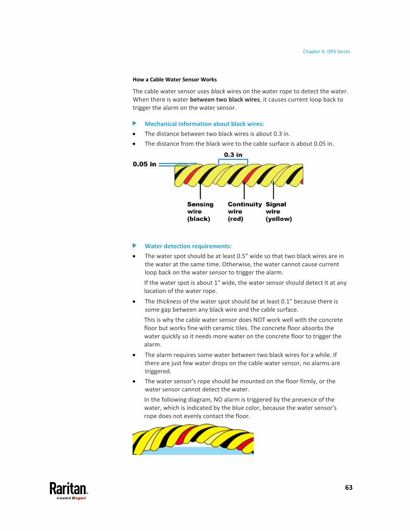
The cable water sensor uses black wires on the water rope to detect the water. When there is water between two black wires, it causes current loop back to trigger the alarm on the water sensor.
Mechanical information about black wires:
• The distance between two black wires is about 0.3 in.
• The distance from the black wire to the cable surface is about 0.05 in.
Water detection requirements:
• The water spot should be at least 0.5" wide so that two black wires are in the water at the same time. Otherwise, the water cannot cause current loop back on the water sensor to trigger the alarm.
If the water spot is about 1" wide, the water sensor should detect it at any location of the water rope.
• The thickness of the water spot should be at least 0.1" because there is some gap between any black wire and the cable surface.
This is why the cable water sensor does NOT work well with the concrete floor but works fine with ceramic tiles. The concrete floor absorbs the water quickly so it needs more water on the concrete floor to trigger the alarm.
• The alarm requires some water between two black wires for a while. If there are just few water drops on the cable water sensor, no alarms are triggered.
• The water sensor's rope should be mounted on the floor firmly, or the water sensor cannot detect the water.
In the following diagram, NO alarm is triggered by the presence of the water, which is indicated by the blue color, because the water sensor's rope does not evenly contact the floor.

Chapter 6: DPX Series
64

65
This chapter shows how to mix different types of sensor packages on a sensor port of a Raritan or Legrand product. Other sensor-mixing connections than those shown in this chapter are NOT supported.
Warning: SRC does NOT support these other Raritan environmental sensor packages: DPX, DPX2, DPX3 (except for the DPX3-ENVHUB4 sensor hub). Therefore, SRC does not support any sensor-mixing connections described in this chapter.
Make sure your Raritan and Legrand products have been upgraded to version 3.4.20 or later to support these sensor-mixing combinations.
In most illustrations below, any DX or DPX3 sensor package can be replaced with a DX2 sensor package.
For those illustrations where DX, DPX3 and DX2 are interchangeable, they are all marked with the following oval image.
Important: Unlike DX or DPX3 series, DX2 CANNOT be connected with DPX sensor package(s).
In This Chapter
Cascading DX2, DX and DPX3 Sensor Packages .................................................. 65 Mixing DPX, DPX2, DPX3, DX and DX2 Sensor Packages ..................................... 66
Cascading DX2, DX and DPX3 Sensor Packages
You can mix DX2, DX and DPX3 in a sensor chain consisting of up to 12 sensor packages. The following diagram illustrates such a sensor-mixing chain.
Chapter 7 Sensor-Mixing Connections
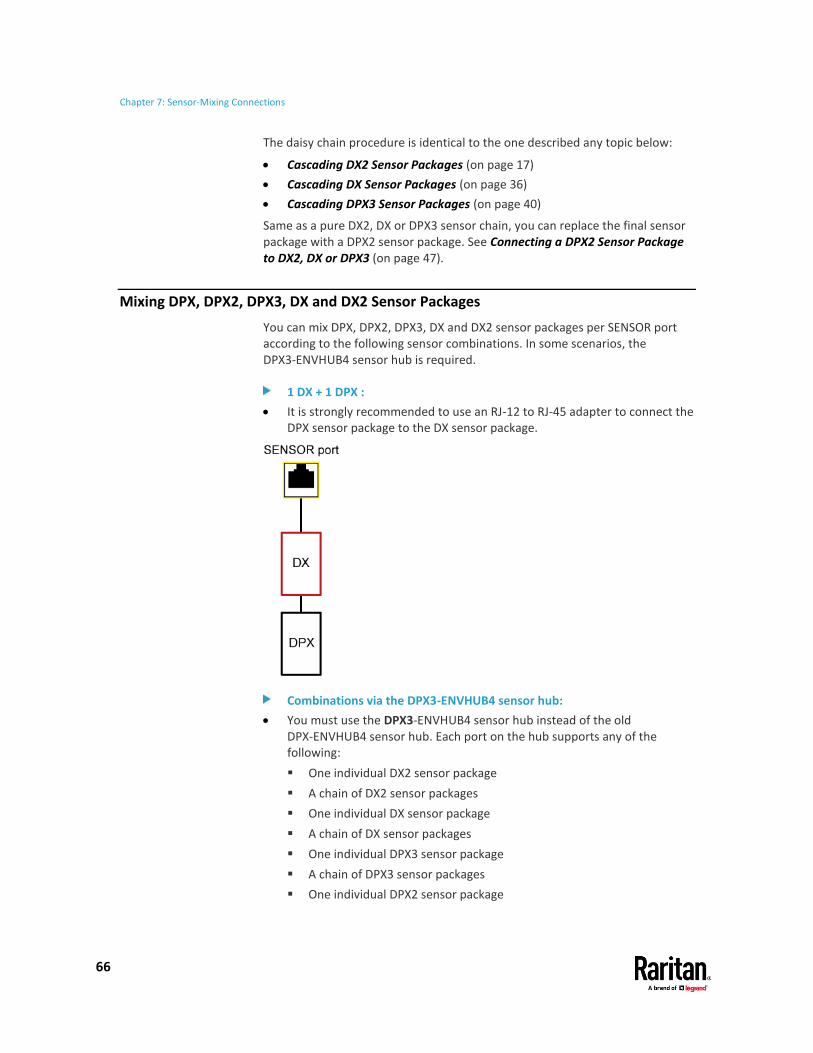
Chapter 7: Sensor-Mixing Connections
66
The daisy chain procedure is identical to the one described any topic below:
• Cascading DX2 Sensor Packages (on page 17)
• Cascading DX Sensor Packages (on page 36)
• Cascading DPX3 Sensor Packages (on page 40)
Same as a pure DX2, DX or DPX3 sensor chain, you can replace the final sensor package with a DPX2 sensor package. See Connecting a DPX2 Sensor Package to DX2, DX or DPX3 (on page 47).
Mixing DPX, DPX2, DPX3, DX and DX2 Sensor Packages
You can mix DPX, DPX2, DPX3, DX and DX2 sensor packages per SENSOR port according to the following sensor combinations. In some scenarios, the DPX3-ENVHUB4 sensor hub is required.
1 DX + 1 DPX :
• It is strongly recommended to use an RJ-12 to RJ-45 adapter to connect the DPX sensor package to the DX sensor package.
Combinations via the DPX3-ENVHUB4 sensor hub:
• You must use the DPX3-ENVHUB4 sensor hub instead of the old DPX-ENVHUB4 sensor hub. Each port on the hub supports any of the following:
▪ One individual DX2 sensor package
▪ A chain of DX2 sensor packages
▪ One individual DX sensor package
▪ A chain of DX sensor packages
▪ One individual DPX3 sensor package
▪ A chain of DPX3 sensor packages
▪ One individual DPX2 sensor package

Chapter 7: Sensor-Mixing Connections
67
▪ One individual DPX sensor package

Chapter 7: Sensor-Mixing Connections
68
• An RJ-12 to RJ-45 adapter is recommended to connect a DPX or DPX2 sensor package to DPX3-ENVHUB4.
• In the following diagrams, the sensor package in "green" can be replaced by a DPX2 sensor package. The sensor package in "blue" can be one DPX2, DPX3, DX or DX2 sensor package.
This section only illustrations the following three combinations, but actually there are tens of different combinations by using the DPX3-ENVHUB4 sensor hub.

Chapter 7: Sensor-Mixing Connections
69

Chapter 7: Sensor-Mixing Connections
70
Sensor mixing with DX2, DX and DPX3 in a chain:
In the above diagrams, any DPX3 sensor package can be replaced by a DX2 or DX sensor package, or vice versa.
If intended, you can also mix DX2, DX and DPX3 sensor packages in a sensor chain. See Cascading DX2, DX and DPX3 Sensor Packages (on page 65).

71
General DX2, DX, DPX2 and DPX3 sensor packages:
DPX2, DPX3, DX and DX2 sensor package support the total cabling length up to 98 feet (30 meters), except for DX-PD2C5 and DX2-DH2C2.
Exception -- DX2-DH2C2 and DX-PD2C5:
DX2-DH2C2 and DX-PD2C5 support a maximum cabling length of 29 feet (9 meters) instead of 98 feet (30 meters). The following illustrates DX2-DH2C2 cabling restriction, but the same principle also applies to DX-PD2C5.
• The length from the PDU to DX2-DH2C2 is up to 16 feet (5 meters).
• The length from DX2-DH2C2 to the connected door handle is up to 13 feet (4 meters).
Appendix A Supported Maximum Sensor Distance

Appendix A: Supported Maximum Sensor Distance
72
Raritan sensor hubs:
A sensor hub is used to increase the total distance of a sensor package. There are two sensor hubs: DPX-ENVHUB4 and DPX3-ENVHUB4.
Different sensor hubs support different sensor packages:
• DPX-ENVHUB4 supports the DPX sensor packages only.
• DPX3-ENVHUB4 supports all Raritan sensor packages, including DPX, DPX2, DPX3, DX and DX2.
Each sensor port on a Raritan or Legrand product, such as a PDU, supports only one Raritan sensor hub so DO NOT cascade sensor hubs.
DPX series:
DPX series' supported distance is determined by the length of the sensor cable pre-installed (or provided) by Raritan. DO NOT extend or modify the cabling length with any tool other than Raritan's sensor hubs.
DPX connection restriction and illustration:
When using a DPX-ENVHUB4 sensor hub, the maximum cabling distance between the Raritan or Legrand product (such as a PDU) and the sensor hub is 33 feet (10 m).
The following illustrates the maximum distance when connecting DPX sensor packages with a maximum 16 feet (5 m) sensor cable via a DPX-ENVHUB4 sensor hub.
• The sum of a DPX-T3H1 sensor cable's length is 16 feet (5 meters).
• The total cabling length between the Raritan or Legrand product and one DPX-T3H1 is 49 feet (15 meters) as illustrated below.
Note that the length 16 feet (5 meters) is the length of each DPX-T3H1 sensor cable, which is defined in the above diagram.
Raritan or Legrand product, such as a PDU
33 feet (10 m)
1 DPX-ENVHUB4 hub
16 feet (5 m)
Up to 4 DPX-T3H1 sensor packages

73
The maximum number of sensors and actuators that can be managed per sensor port of a Raritan product or Legrand PDU is 32 sensors or actuators. These sensors may be part of a "sensor package" containing multiple sensors or actuators, such as a DX2-T1H1, which is 1 package with 2 sensors. The maximum number of packages that can be managed per sensor port is 12 packages.
Note that though Raritan's EMX2-888 has 8 sensor ports, the number of "externally-connected" sensors/actuators that it can manage is limited to 128.
Calculation examples for managed sensors/actuators:
A sensor package may contain more than one sensor/actuator, and each sensor or actuator is counted as an individual function. You cannot exceed 32 functions per sensor port.
For example:
• A DX2-T1H1 contains 2 sensors so it has 2 functions. The DX2-T1H1 is a "package", so there is a maximum limit of 12.
2 functions * 12 packages = 24 functions
Therefore, you can manage up to 12 DX2-T1H1 packages per sensor port, without exceeding either function or package maximum.
• A DX-D2C6 contains 6 sensors and 2 actuators so it has 8 functions.
8*4 = 32
Therefore, you can manage up to four DX-D2C6 packages per sensor port.
Tip for DX sensor connection:
If intended, you can connect 12 DX sensor packages without exceeding the maximum of managed sensors/actuators per sensor port -- 32. All you need to do is manage "partial" sensors/actuators of each DX and unmanage the rest.
For example, you can connect 12 DX-D2C6 sensor packages to a sensor port by managing only two functions of each DX-D2C6.
12*2 = 24
All 24 sensors/actuators can be managed because it is less than 32.
Appendix B Supported Maximum Number of Sensors and Actuators
74
This section shows the factory specifications of Raritan DPX, DPX2, DX2, and DPX3 environmental sensor packages. Calibration is not required for these sensor packages.
In This Chapter
DPX Sensor Accuracy .......................................................................................... 74 DPX2 Sensor Accuracy ........................................................................................ 74 DX2 Sensor Accuracy .......................................................................................... 74
DPX Sensor Accuracy
• Temperature: +/-2 degrees Celsius (+/-3.6 degrees Fahrenheit)
• Humidity: +/-5% (when humidity < 60%) or +/-8% (when humidity > 60%)
• Differential air pressure: +/-1.5%
• Air flow: +/-6.5%
DPX2 Sensor Accuracy
• Temperature: +/-1.0 degree Celsius (+/-1.8 degrees Fahrenheit)
• Humidity: +/-3.5% (when humidity = 10% to 90%)
DX2 Sensor Accuracy
• Temperature: +/-1.0 degree Celsius (when temperature = 20 to 70 degrees Celsius)
▪ +/-1.0 degree Celsius is equal to +/-1.8 degrees Fahrenheit
• Humidity: +/-3.5% (when humidity = 10% to 90%)
Appendix C Sensor Measurement Accuracy

75
DPX2, DPX3, DX and DX2 sensor packages automatically upgrade or downgrade their firmware after being connected to a Raritan or Legrand PDU or a Raritan EMX that supports these sensor packages. This way it ensures that these sensor packages work properly with the connected PDU or EMX.
Automatic upgrade or downgrade is determined by comparing DPX2, DPX3, DX or DX2 sensor firmware against the environmental sensor firmware stored inside the connected PDU or EMX. A downgrade can be performed only when the PDU- or EMX-provided sensor firmware is either greater than or equal to the minimum firmware version requested by the connected sensor packages.
Note that a DPX sensor package does NOT support the automatic firmware update feature, and you do NOT need to manually update it.
Tip: Information regarding current sensor firmware version and the sensor's firmware update time is available in the Device Information dialog. Choose Maintenance > Device Information > Peripheral Devices in the web interface of your Raritan/Legrand PDU or Raritan EMX.
Appendix D Sensor Firmware Update

76
The model name of a Raritan environmental sensor package consists of sensor family, sensor functions and the total number of the specified functions.
[Family] - [Function_1] [Number_1]
- OR -
[Family] - [Function_1] [Number_1] [Function_2]
[Number_2]
[Family] is DPX, DPX2, DPX3, DX or DX2.
[Number_1] and [Number_2] are integer numbers.
[Function_1] and [Function_2] are abbreviations representing diverse functions.
Note: Some sensor packages may indicate the main function only rather than indicating all functions in its name. For example, the name of DX-VBR indicates that it contains the vibration sensor while it does not indicate the contact closure sensor that it also contains.
Abbreviations Functions
AF Air flow sensors
CC or C Contact closure sensor terminals
D Dry contact signal terminals for actuators
DH The port to connect a door handle
DP Differential air pressure sensors
H Humidity sensors
PD "Powered" dry contact signal terminals
PIR Passive infrared occupancy sensor
T Temperature sensors
VBR Vibration sensors
WSC or WC Cable water sensors
WSF Floor-mounted water sensors
Appendix E Sensor Naming Conventions

Appendix E: Sensor Naming Conventions
77

79
A
Adjusting Dip Switches • 22, 25, 29, 30, 33, 37 Available DPX Sensor Packages • 2, 49, 54 Available DPX2 Sensor Packages • 2, 43 Available DPX3 Sensor Packages • 2, 38 Available DX Sensor Packages • 2, 5, 17, 20, 56 Available DX2 Sensor Packages • 2, 5, 21, 56
B
Bracket Installation • 9
C
Cable Water Sensor • 49, 62 Cascading DPX3 Sensor Packages • 39, 40, 66 Cascading DX Sensor Packages • 36, 66 Cascading DX2 Sensor Packages • 8, 10, 12, 17, 66 Cascading DX2, DX and DPX3 Sensor Packages • 17,
36, 40, 65, 70 Configuring a DPX Contact Closure Sensor • 58, 59 Configuring DX2-CC2's Normal State • 13, 16, 17 Connecting a DPX Sensor Package to an Air
Pressure Sensor • 53 Connecting a DPX2 Sensor Cable • 44 Connecting a DPX2 Sensor Package to DX2, DX or
DPX3 • 42, 44, 47, 66 Connecting Detectors/Actuators to DX • 22, 25, 29,
30, 33, 34 Connecting Detectors/Switches to DPX-CC2-TR •
56 Connecting Detectors/Switches to DX2-CC2 • 7, 13,
14 Connecting Tubes • 53 Connection and Disconnection • 44 Contact Closure Sensor LEDs • 59
D
Disconnecting a DPX2 Sensor • 46 DPX Air Flow Sensors • vi, 49, 51 DPX Contact Closure Sensors • 5, 17, 21, 49, 54 DPX Differential Air Pressure Sensors • 49, 52 DPX Floor Water Sensors • 55, 60 DPX Sensor Accuracy • 74 DPX Series • 48
DPX Temperature and Humidity Sensors • 11, 39, 44, 49, 50
DPX2 Sensor Accuracy • 74 DPX2 Series • 42 DPX2 Temperature and Humidity Sensors • 11, 39,
43, 50 DPX3 LED States • 39 DPX3 Series • 38 DPX3 Temperature and Humidity Sensors • 11, 38,
39, 44, 50 DX Series • 19 DX2 LED States • 10, 11, 44 DX2 Sensor Accuracy • 74 DX2 Series • 4 DX2 Temperature and Humidity Sensors • 5, 10,
39, 44, 50 DX2-CC2 Contact Closure Sensor LEDs • 16, 17, 23,
26, 29, 31, 33, 59 DX2-CC2 Contact Closure Sensors • 5, 12 DX2-DH2C2 Door Handle Controller • 2, 3, 5, 6, 18 DX2-DH2C2 LED States • 9 DX-D2C6 • 20, 21 DX-D4C3 • 20, 29 DX-PD2C5 • 2, 3, 20, 24, 37 DX-PIR • 20, 26 DX-VBR • 20, 32
F
Floor-mounted Water Sensor • 49, 60
H
How a Cable Water Sensor Works • 63 How a Floor-mounted Water Sensor Works • 61
I
Introduction to Environmental Sensor Packages • 1
M
Making Connections • 33 Mixing DPX, DPX2, DPX3, DX and DX2 Sensor
Packages • 66
P
Pre-installed DX Brackets • 33
Index

Index
80
Products Supporting Raritan Sensor Packages • vii, 1, 3
S
Sensor Comparison • 2 Sensor Firmware Update • 9, 11, 23, 26, 29, 31, 33,
75 Sensor Measurement Accuracy • 74 Sensor Naming Conventions • 5, 20, 38, 43, 49, 76 Sensor Overview • 2 Sensor Support Guidelines • vii, 3 Sensor-Mixing Connections • 65 Supported Maximum Number of Sensors and
Actuators • vi, 2, 18, 37, 41, 73 Supported Maximum Sensor Distance • 2, 8, 24,
71
W
What's New in the Environmental Sensors and Actuators Guide • vi