enviroswitch™ three phase solid state switch installation...
TRANSCRIPT

Three Phase Solid State Switch - Page 1 of 22
EnviroSwitch™
Three Phase Solid State Switch
Installation & Commissioning Guide
Version 3 June 2008
12.5kVA, 25kVA & 50kVA

Three Phase Solid State Switch - Page 2 of 22
EnviroSwitch™ Three Phase Solid State Switch
IMPORTANT WARNING Failure to read and comply with this manual may result in damage to the EnviroSwitch Unit and driven equipment and may render the warranty invalid.
1. Only a competent electrician should carry out the electrical installation.
2. EnviroSwitch must be earthed with an earthing conductor connected to the earthing terminal.
3. Before installation check the application rating plate to ensure that the EnviroSwitch is correctly rated for the application.
4. Internal components and areas of the control circuit boards, (except the isolated I/O terminals), can be at mains potential when the EnviroSwitch is connected to a three-phase supply. The voltage is extremely dangerous and may cause death or severe injury if you come into contact with it.
5. When the EnviroSwitch is connected to the mains, the load connections U, V and W should be treated as being live even if the load is not running.
6. The control I/O terminals are isolated from mains potential but the relay outputs may have dangerous voltages present even if the mains are not connected.
7. Do not make any connections when the EnviroSwitch is connected to live mains.
8. Do not make voltage withstand tests on any part of the EnviroSwitch without isolating the unit.
9. Do not touch IC-circuits on the PCB. Certain items are static-sensitive and static voltage discharge may destroy the components.
10. Make sure the cover is closed before applying mains voltage to the EnviroSwitch.
11. Updated and current Installation and Commissioning Guides are maintained on the EMS (European) web site at http://www.EnviroStart.com; always check the web site for latest issue documents before commencing installation.

Three Phase Solid State Switch - Page 3 of 22
CONTENTS
1 INTRODUCTION ............................................................................................................... 5 1.1 FEATURES ............................................................................................................ 5
2 RATING INFORMATION .................................................................................................. 6 2.1 CORRECT ENVIROSWITCH SIZING ................................................................... 6
2.2 RATING: 240V/415V, 208/480V, 570V & 690V ..................................................... 6
2.3 CE DECLARATION OF CONFORMITY ................................................................ 7
3 SPECIFICATION .............................................................................................................. 8 3.1 TECHNICAL SPECIFICATION .............................................................................. 8
3.2 HEAT LOSSES ...................................................................................................... 8
3.3 HEAT DISSIPATION .............................................................................................. 8
3.4 SELECTING A FAN ............................................................................................... 9
3.5 CONTROL PANELS WITH MULTIPLE ENVIROSWITCH .................................... 9
3.6 COOLING FAN POSITION .................................................................................... 9
3.7 CABINET COOLING FANS ................................................................................... 9
3.8 POWER LOSSES .................................................................................................. 9
4 INSTALLATION .............................................................................................................. 10 4.1 IMMUNITY FROM INTERFERENCE ................................................................... 10
4.2 LIGHTNING STRIKES / VERY HIGH VOLTAGE TRANSIENTS ........................ 10
4.3 CONTROL VOLTAGE TRANSIENTS .................................................................. 10
4.4 INPUT / OUTPUT CONTROL CONNECTIONS .................................................. 10
4.5 EMISSIONS ......................................................................................................... 10
4.6 VENTILATION ...................................................................................................... 10
4.7 CABLE AND INPUT FUSE RATINGS ................................................................. 10
5 CONNECTION ................... 11
5.1 TERMINAL FUNCTION AND LOCATION ........................................................... 11
5.2 MAINS CONNECTION SCHEMATIC DRAWING ................................................ 12
5.3 CAPACITIVE LOADS - CHOKE PACKS ............................................................. 13
5.4 BASIC CONNECTIONS MINIMUM REQUIREMENTS ....................................... 13
5.5 CONTROL CONNECTIONS PLC CONTROL ..................................................... 14
5.6 PRE-COMMISSIONING CHECKS ....................................................................... 14
5.7 COMMISSIONING INSTRUCTIONS ................................................................... 14
5.8 USER ADJUSTMENTS MAP (PCB) (12.5 - 50kVA) ............................................ 15
6 USER CONTROL FEATURES ....................................................................................... 16 6.1 START AND STOP FUNCTIONS ........................................................................ 16
6.2 VOLTAGE SELECTION ....................................................................................... 16
6.3 DEFAULT DIP SWITCH SELECTION ................................................................. 17
6.4 SUPPLY FREQUENCY SELECT ........................................................................ 17
6.5 EMERGENCY RUN FUNCTION .......................................................................... 17
6.6 FAULT CONDITION DIAGNOSTICS ................................................................... 17

Three Phase Solid State Switch - Page 4 of 22
6.7 READY RELAY .................................................................................................... 18
6.8 RUN RELAY..............…..…………………………….......……………………………18
6.9 FAULT RELAY ..................................................................................................18
6.23 LED INDICATORS ..............................................………….………………………. 19
APPENDICES 1 MECHANICAL DRAWINGS ………………………………………………………….. 20
2 TESTING AND REPLACEMENT OF THYRISTORS ………………………………. 21
3 GENERAL SPECIFICATIONS ………………………………………………………... 22
4 FAN SPECIFICATION ...........................................................................................22

Three Phase Solid State Switch - Page 5 of 22
1 INTRODUCTION
Thank you for choosing the EnviroSwitch Solid State Switch. This system has been designed specifically with power factor correction capacitor switching in mind however it can be used for any solid state switching application if required,
The system has been designed with ease of use and set up in mind. The majority of applications will operate effectively without the need to make any changes to the default settings however should such changes be necessary please do read through this Installation and Commissioning Guide so as to better understand the effects of the changes you are making.
Components used in the manufacture of this system have been selected with reliability in mind and have generally been over-rated for the power of the unit manufactured. Using the standard IQA, (Institute of Quality Assurance), methodologies the expected lifetime of EnviroSwitch is rated at 130,000 hours continuous use, (15 years),
In the unlikely event that you do need further support please contact your local EMS (European) Distributor or failing that contact us directly either by e-mail or fax. All details of how to contact us are available on our web site at http://www.EnviroSwitch.com, please remember that we are constantly updating documentation and information about EnviroSwitch, all such information is posted and publicly available on the web site.
1.1 FEATURES The EnviroSwitch is a high specification digital Solid State switch available in 12.5kVA, 25kVA and 50kVA sizes. (23A through to 75A)
EASE OF INSTALLATION AND CONFIGURATION
HIGH SWITCHING FREQUENCY (Resistive/Inductive no limit, Capacitive limited to re-switching when capacitor voltage has dropped to <10V).
SWITCHABLE EMERGENCY RUN
START/STOP COMMAND FUNCTION CONTROLLABLE WITH PNP, (SINK), OR NPN, (SOURCE), INPUT OR SIMPLE CLOSED CONTACT SWITCHING
SUPPLY PRESENT, FEED PRESENT AND THYRISTOR FAULT DETECTION
READY, RUN AND FAULT RELAYS. (2x N/O, 2x N/C 2kVA contacts on each)
FULL SYSTEM STATUS LED's
ON PCB SYSTEM CPU RESET BUTTON
RUGGED HOUSING, IP43, NEMA 1. (Can be fitted into cabinet to increase to IP 65)
ON-BOARD CONFIGURABLE SUPPLY VOLTAGE AND FREQUENCY SETTINGS

Three Phase Solid State Switch - Page 6 of 22
2 RATING INFORMATION
2.1 CORRECT ENVIROSWITCH SELECTION The EnviroSwitch must be rated according to the load rated current. (kVA)
Please note that these environmental factors (temperature, ventilation, altitude, ambient temperature & relative humidity) do affect sizing and failing to take proper notice of such conditions will invalidate any warranty associated with the system as supplied. Where the EnviroSwitch is expected to operate outside the normal specifications and you are uncertain as to the selection of a unit please contact EMS (European) or your local Distributor, we will always be happy to assist to ensure your application is correctly supported.
2.2 VOLTAGE RATINGS AVAILABLE: 220V/400V Ratings are based on the full load rated current. The cable and fuses have to be sized in accordance with the rated output of the unit applicable to the voltage selected on the PCB. Recommendations with regard to fuse and cable ratings are made within this guide, (section 4.7), however it is the responsibility of the installation engineer to ensure that all such fittings are properly rated and specified in accordance with local requirements and conditions.

Three Phase Solid State Switch - Page 7 of 22
2.3 CE DECLARATION OF CONFORMITY
MANUFACTURERS DECLARATION OF CONFORMITY This declaration covers all EnviroSwitch Solid State Switch units.
This product fulfils the following European Community Directives when applied as follows:
Low Voltage Directive
The above products fulfil the Low Voltage Directive 73/23/EEC, 89/336/EEC and 93/68/EEC amendment for industrial equipment; however, they must be installed to general good electrical engineering practices and regulations by a suitably qualified person with strict reference to the instructions in the product's Technical Manual.
EMC Directive
The above products are intended to be a component in a system or a machine. They must be mounted into an appropriate enclosure and system designed to fulfil the CE directives plus IEC and local industrial standards. Units must be installed by a suitably qualified person to comply with general good electrical engineering practices and regulations with strict reference to the instructions in the product's Technical Manual. To meet all EMC directives, the above products are available with an optional RFI Filter.
IEC-1000-4-2 Level 3; IEC-1000-4-3 Level 3; IEC-1000-4-4 Level 4; IEC-1000-4-5 Level 3; IEC-1000-4-12 Level 3.
The above is based on test results from an independent test laboratory (Steatite Group Ltd.) to test specification EN 50081-2, EN 50082-1 and EN 50082-2.
Harmonised Standards Applicable
BS EN 6094.4.4 (which calls on EN 56011); EN 55022; EN 51000.4.2; EN 61000.4.3; EN 51000.4.4; EN 61000.4.5; EN 61000.4.6; EN 61000.4.8; EN 61000.4.11; BS EN 50081.1; BS EN 50081.2; BS EN 50082.2; EN 6094.4.2; IEC-947-4-1; IEC-68-2-6, (NFC2076; BV1); IEC-947-4-2.
Electrical Requirements Specification G5/4 (2002)
Dated: May 2007
Three Phase Solid State Switch - Page 8 of 22
3 GENERAL SPECIFICATION
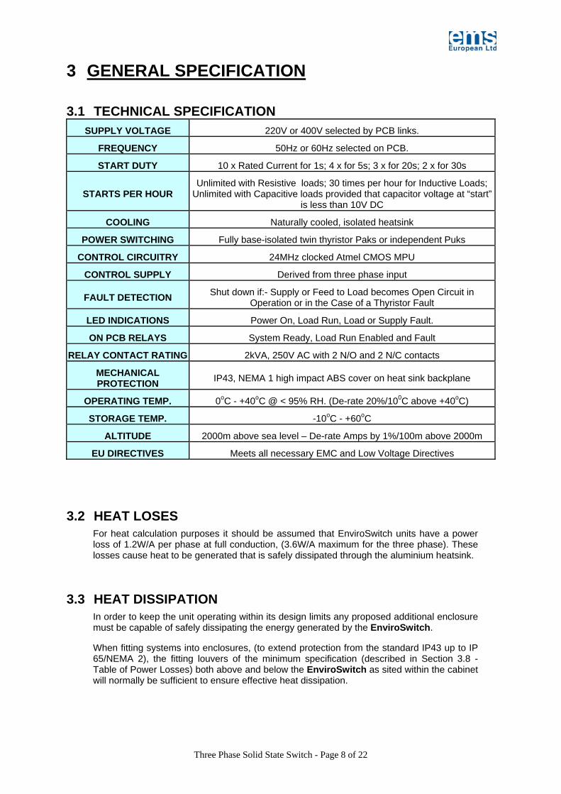
3.1 TECHNICAL SPECIFICATION SUPPLY VOLTAGE 220V or 400V selected by PCB links.
FREQUENCY 50Hz or 60Hz selected on PCB.
START DUTY 10 x Rated Current for 1s; 4 x for 5s; 3 x for 20s; 2 x for 30s
STARTS PER HOUR Unlimited with Resistive loads; 30 times per hour for Inductive Loads;
Unlimited with Capacitive loads provided that capacitor voltage at “start” is less than 10V DC
COOLING Naturally cooled, isolated heatsink
POWER SWITCHING Fully base-isolated twin thyristor Paks or independent Puks
CONTROL CIRCUITRY 24MHz clocked Atmel CMOS MPU
CONTROL SUPPLY Derived from three phase input
FAULT DETECTION Shut down if:- Supply or Feed to Load becomes Open Circuit in Operation or in the Case of a Thyristor Fault
LED INDICATIONS Power On, Load Run, Load or Supply Fault.
ON PCB RELAYS System Ready, Load Run Enabled and Fault
RELAY CONTACT RATING 2kVA, 250V AC with 2 N/O and 2 N/C contacts
MECHANICAL PROTECTION IP43, NEMA 1 high impact ABS cover on heat sink backplane
OPERATING TEMP. 0oC - +40oC @ < 95% RH. (De-rate 20%/100C above +40oC)
STORAGE TEMP. -10oC - +60oC
ALTITUDE 2000m above sea level – De-rate Amps by 1%/100m above 2000m
EU DIRECTIVES Meets all necessary EMC and Low Voltage Directives
3.2 HEAT LOSES For heat calculation purposes it should be assumed that EnviroSwitch units have a power loss of 1.2W/A per phase at full conduction, (3.6W/A maximum for the three phase). These losses cause heat to be generated that is safely dissipated through the aluminium heatsink.
3.3 HEAT DISSIPATION In order to keep the unit operating within its design limits any proposed additional enclosure must be capable of safely dissipating the energy generated by the EnviroSwitch.
When fitting systems into enclosures, (to extend protection from the standard IP43 up to IP 65/NEMA 2), the fitting louvers of the minimum specification (described in Section 3.8 - Table of Power Losses) both above and below the EnviroSwitch as sited within the cabinet will normally be sufficient to ensure effective heat dissipation.

Three Phase Solid State Switch - Page 9 of 22
3.4 SELECTING A CABINET COOLING FAN Take the heat dissipation figure of the required EnviroSwitch model from Section 3.10, Table of Power Losses. Compare this figure with the fan heat disposal figure in Section 3.9, Table of Fan Data and select a fan with a greater heat disposal figure than that calculated.
3.5 CONTROL PANELS WITH MULTIPLE ENVIROSWITCHS If more than one EnviroSwitch is to be installed in a single enclosure the heat dissipation figures should be added together before selecting cooling system requirements.
3.6 COOLING FAN POSITION The fans should be positioned below the EnviroSwitch power assembly to allow cool air to be drawn into the path of the power assembly fans. Outlet Filters or louvers should be positioned close to the top of the enclosure and in the path of the airflow. These should be approximately double the fan apertures to ensure that the air flow is as free as possible.
3.7 CABINET COOLING FAN DETAIL The fans should be positioned in the cabinet, wherever possible, below the EnviroSwitch. The aperture to which the fans are fitted should always be large enough to allow free flow of air, any filters fitted should be selected to minimise their interruption to air flow. Such filters should be regularly inspected to ensure that they are clean.
PAPST FAN MODEL NO.’S
FLOW RATE EXC. FILTER
(L/s.) FLOW RATE INC.
FILTER (L/s.) HEAT DISP. EXC.
FILTER (W) HEAT DISP.
INC. FILTER (W)
8500N/8550N 10.4 8.3 117 93
4600N/4650N 38.7 31 477 382
7600N/7650N 87.3 71 1,010 805
7400N/7450N 106 85 1,166 935
6028S/6078 106 93.3 1,283 1,026
3.8 TABLE OF POWER LOSSES
MODEL POWER
ASSEMBLY LOSSES IN W
(R & I)
POWER ASSEMBLY
LOSSES IN W(C)
CONTROL LOSSES
IN W
TOTAL LOSSES
IN W (R & I)
TOTAL LOSSES
IN W (R & I)
MINIMUM LOUVRE AREA (TWO REQUIRED)
(R & I LOADS)
TPPFCS - 12 90 15 10 105 25 0.0156 Sq. M
TPPFCS - 25 162 30 10 172 40 0.0156 Sq. M
TPPFCS - 50 270 50 20 290 70 0.0625 Sq. M
USE TABLE OF FAN DATA IN SECTION 3.7 TO SELECT CORRECT CABINET FAN
Three Phase Solid State Switch - Page 10 of 22
4 INSTALLATION
4.1 IMMUNITY FROM INTERFERENCE EnviroSwitch generally has a high level of immunity to externally generated interference. However the following good practices should be observed:
4.2 LIGHTNING STRIKES/VERY HIGH VOLTAGE TRANSIENTS In areas subject to frequent lightning strikes or other high voltage transients, a suitably rated metal oxide Varistor (MOV) should connect each input line to earth.
4.3 CONTROL VOLTAGE TRANSIENTS Where the control supply to the EnviroSwitch is thought to be subject to mains-borne interference a suitable line filter with transient interference suppression should be fitted between the control supply and the EnviroSwitch.
4.4 INPUT/OUTPUT CONTROL CONNECTIONS To avoid 'interference pick up' all input and output control cables should be kept as short as possible and should wherever possible, be shielded. If noise free lines cannot be guaranteed, an interposing relay with suitable suppression must be used, this should be mounted as close to the EnviroSwitch as possible.
4.5 EMISSIONS EnviroSwitch units produce negligible Radio Frequency Interference (RFI) and no external filters are required in normal circumstances.
4.6 VENTILATION The EnviroSwitch must be mounted vertically with the cooling fans, (if fitted), directing the air upwards. A free space of 85mm must be allowed above and below the unit. See section 3.2 through 3.8 for further information.
4.7 CABLE AND INPUT FUSE RATINGS Incoming fuses and power cables must comply with the ratings as shown in the table below. It is recommended that all cable be tri-rated compliant with BS 6231 and that all fuses be fully rated, bolt fitting, compliant with BS 88 Part 2.
The detail below refers to new installations. In cases where the EnviroSwitch is being fitted into an existing installation then the cable should be rated according to the fuses already fitted. (IEE 17th Regulations). The AWG and MLM designations are per Table 310-16 of NEC 2005 and relate to copper conductors. (60oF up to 100A and 75oF above 101A).To comply with BSEN 60831 when used with capacitive loads, cables must be rated at 1.5 times the nominal capacitor current, that is, for a 50kVAr unit the nominal current is 67A at 400V; cables must be rated at 100A in this case. The cables must also be sized so that the correct protection is provided by the feeder device.
Three Phase Solid State Switch - Page 11 of 22
TABLE OF FUSE AND CABLE RATINGS (CAPACITIVE)
MODEL FUSE RATING
CABLE RATING
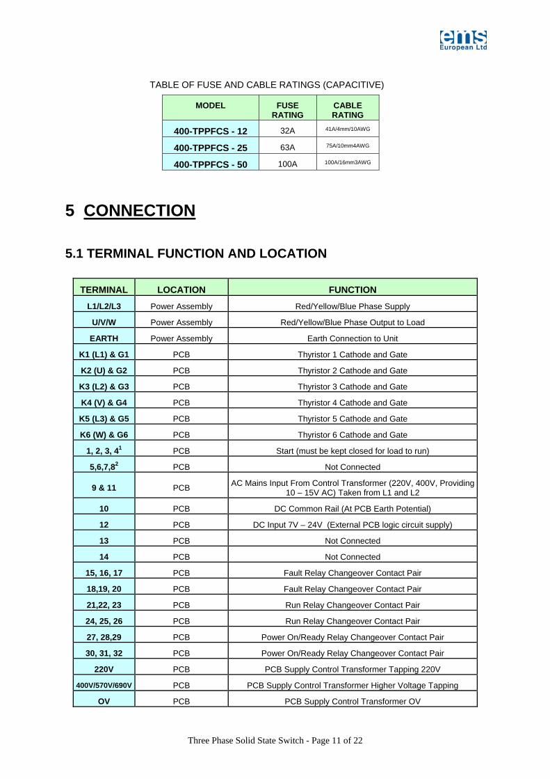
400-TPPFCS - 12 32A 41A/4mm/10AWG
400-TPPFCS - 25 63A 75A/10mm4AWG
400-TPPFCS - 50 100A 100A/16mm3AWG
5 CONNECTION 5.1 TERMINAL FUNCTION AND LOCATION
TERMINAL LOCATION FUNCTION
L1/L2/L3 Power Assembly Red/Yellow/Blue Phase Supply
U/V/W Power Assembly Red/Yellow/Blue Phase Output to Load
EARTH Power Assembly Earth Connection to Unit
K1 (L1) & G1 PCB Thyristor 1 Cathode and Gate
K2 (U) & G2 PCB Thyristor 2 Cathode and Gate
K3 (L2) & G3 PCB Thyristor 3 Cathode and Gate
K4 (V) & G4 PCB Thyristor 4 Cathode and Gate
K5 (L3) & G5 PCB Thyristor 5 Cathode and Gate
K6 (W) & G6 PCB Thyristor 6 Cathode and Gate
1, 2, 3, 41 PCB Start (must be kept closed for load to run)
5,6,7,82 PCB Not Connected
9 & 11 PCB AC Mains Input From Control Transformer (220V, 400V, Providing 10 – 15V AC) Taken from L1 and L2
10 PCB DC Common Rail (At PCB Earth Potential)
12 PCB DC Input 7V – 24V (External PCB logic circuit supply)
13 PCB Not Connected
14 PCB Not Connected
15, 16, 17 PCB Fault Relay Changeover Contact Pair
18,19, 20 PCB Fault Relay Changeover Contact Pair
21,22, 23 PCB Run Relay Changeover Contact Pair
24, 25, 26 PCB Run Relay Changeover Contact Pair
27, 28,29 PCB Power On/Ready Relay Changeover Contact Pair
30, 31, 32 PCB Power On/Ready Relay Changeover Contact Pair
220V PCB PCB Supply Control Transformer Tapping 220V
400V/570V/690V PCB PCB Supply Control Transformer Higher Voltage Tapping
OV PCB PCB Supply Control Transformer OV
Three Phase Solid State Switch - Page 12 of 22
NOTES
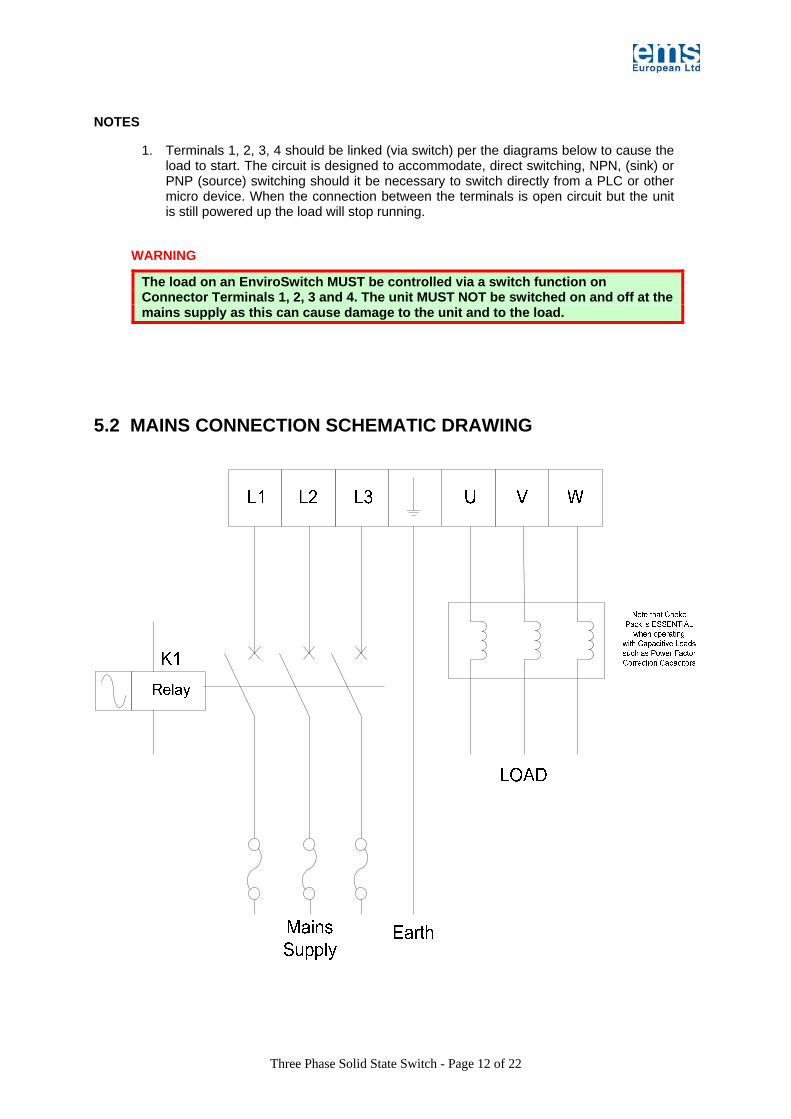
1. Terminals 1, 2, 3, 4 should be linked (via switch) per the diagrams below to cause the load to start. The circuit is designed to accommodate, direct switching, NPN, (sink) or PNP (source) switching should it be necessary to switch directly from a PLC or other micro device. When the connection between the terminals is open circuit but the unit is still powered up the load will stop running.
WARNING
The load on an EnviroSwitch MUST be controlled via a switch function on Connector Terminals 1, 2, 3 and 4. The unit MUST NOT be switched on and off at the mains supply as this can cause damage to the unit and to the load.
5.2 MAINS CONNECTION SCHEMATIC DRAWING
Three Phase Solid State Switch - Page 13 of 22
1
23
22
17
16
4
2
3
Env
iroS
witc
h
K1 (Start)
Overload
Control Live
K1
RunRelay
ControlNeutral
Start
Stop
5.3 CAPACITIVE LOADS – CHOKE PACK REQUIRED
When the EnviroSwitch is being used to switch the supply to a purely capacitive load such as Power Factor Correction Capacitors then it is IMPERATIVE that a suitably rated choke pack is used in the supply to that load. (Note, all EnviroSwitch units are supplied with a set of chokes rated for the unit supplied)
The use of these chokes are necessary to slow down the dI/dt as well as the dV/dt at switch on when the capacitors have no inherent charge in them. (Note the warning in Section 6.1 regarding the starting of capacitive loads).
Wherever possible the chokes should be installed immediately adjacent to the EnviroSwitch however there will be no detrimental effect to the system if they are up to one cable metre from the thyristor outputs.
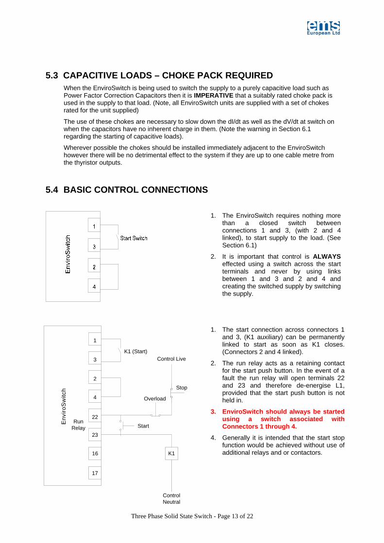
5.4 BASIC CONTROL CONNECTIONS
1. The start connection across connectors 1 and 3, (K1 auxiliary) can be permanently linked to start as soon as K1 closes. (Connectors 2 and 4 linked).
2. The run relay acts as a retaining contact for the start push button. In the event of a fault the run relay will open terminals 22 and 23 and therefore de-energise L1, provided that the start push button is not held in.
3. EnviroSwitch should always be started using a switch associated with Connectors 1 through 4.
4. Generally it is intended that the start stop function would be achieved without use of additional relays and or contactors.
1. The EnviroSwitch requires nothing more than a closed switch between connections 1 and 3, (with 2 and 4 linked), to start supply to the load. (See Section 6.1)
2. It is important that control is ALWAYS effected using a switch across the start terminals and never by using links between 1 and 3 and 2 and 4 and creating the switched supply by switching the supply.

Three Phase Solid State Switch - Page 14 of 22
5.5 CONTROL CONNECTIONS PLC CONTROL
1
23
22
17
16
4
2
3
Env
iroS
witc
h
RunRelay
K1
PLC
Control Live
ControlNeutral
Run
Start
Run Input
Stop
5.6 PRE-COMMISSIONING CHECKS IMPORTANT: Before installation check the rating plate and Section 2 of this manual to ensure that the EnviroSwitch is correctly rated for the application.
1. Check that the voltage for the PCB and frequency selection is correct.
2. Ensure that fans (if fitted) are free to rotate.
3. Ensure that all Switch and Potentiometer settings are set to default. (Section 6.3)
4. Check that the unit is connected correctly as per the proceeding connection diagrams.
5.7 COMMISSIONING INSTRUCTIONS 1. Check that all settings are at 'Default' and the pre-commissioning steps have been followed.
2. Give the run command to the PCB.
3. Check that the Orange “Run” LED illuminates.
4. Using a clamp meter check the current flow in each of the three phase feeds to the load is reasonably balanced, (within 10% of each other).
1. The unit will start as soon as K1 closes and then the “Start” is made. The EnviroSwitch will stop when the “Start” function is made open circuit. (Link also to be made between connectors 2 and 4). In this instance K1 is representative only as it may be any manner of inputs controlling the PLC “run” demand function.
2. The Run Relay is made as the start signal is given the EnviroSwitch to avoid the PLC registering a fault and opening K1 creating a lock-out until a reset signal is delivered.
3. EnviroSwitch should always be started using a switch associated with Connectors 1 through 4.
4. Generally it is intended that the start stop function would be achieved without use of additional relays and or contactors.

Three Phase Solid State Switch - Page 15 of 22
5.8 PCB SWITCH AND CONTROL LOCATION
6 USER CONTROL FEATURES
6.1 START AND STOP FUNCTION IMPORTANT NOTE
When used with capacitive loads the EnviroSwitch system should be powered, that is, have the power on but NOT be driving a load, for a period of at least 10s prior to making the first start using Connectors 1 through 4. This is to fully utilise the pre-charge function inbuilt into the system. (In this a half wave pulse is sent through to the capacitor to pre-charge the plates to help reduce the inrush at switch on; the 10s is to allow voltage decay to take place to ensure that the dV/dt of the system is not exceeded).
The controlled load is started and stopped by making contact between connector pins 1 and 3 on the PCB. This is a zero voltage contact set. It is important that no control current or voltage be fed to these terminals as this will result in damage to the control microprocessor.
The input circuit is capable of handling both direct start, having connector pins 2 and 4 linked and then making the link between connector pins 1 and 3 either via a switch or
Connections to Thyristor Paks
LED Indicators
Dip Switch
Controls
CPU Soft
Reset Voltage Connections to PCB from Transformer
Relays
Principal Connector Block
CPUPower Assembly

Three Phase Solid State Switch - Page 16 of 22
permanently so that the load starts on power being supplied or from a logic high, (source) or logic low, (sink) from a PLC system.
6.2 VOLTAGE SELECTION
WARNING: Please check these setting are correct before first starting the unit.
All 220/400V units are shipped with the voltage set at 400V;
Should you require that the operating voltage of the unit be changed from 400V to 200V, swap the position of the 400V and 220V marked push-on connectors found on the underside of the PCB.
In the event that you wish to supply the PCB from an external source then you should disconnect the supply leads from the PCB terminals and connect a 208V AC (USA), or 220V AC (ROW) supply between the lead that was on the 0V terminal and the lead that was on the 220V terminal. The lead that was on the 400V terminal could be “docked” safely on the 220V pin of the PCB, or insulated and secured elsewhere. (It is recommended that it be docked to the 220V terminal of the PCB as this is isolated and secure.
All units are supplied with a transformer suitable for use with the voltage you specified on your order. The fundamental requirement is that there be 10V AC fed to the PCB at connector pins 9 and 11. Should you require you can maintain the logic +5V DC on the PCB by providing between 7V and 24V DC on the 0V and +24V connectors 10 and 12.
12.5kVA through 50kVA PCB Power Connections
6.3 DEFAULT DIP SWITCH SETTINGS

Three Phase Solid State Switch - Page 17 of 22
The unit is set to the 'Default Settings' before leaving the factory. These should be tried first and further adjustments only made where necessary to 'fine tune' the EnviroSwitch.
ADJUSTMENT FUNCTION DEFAULT SETTING
RESULT SEE SECTION
Switches 1 to 11 Not Connected Switch 12 50/60Hz Select OFF 50Hz Selected 6.11
Switches 13 to 17 Not Connected Switch 18 Emergency Run OFF Normal Operation 6.15
Switches 19 & 20 Not Connected Potentiometer VR1 Not Connected
See Section 5.8 for DIP Switch location on PCB.
6.4 SUPPLY FREQUENCY SELECTION
This switch function should be set to reflect the supply frequency of the three-phase mains supply.
Switch settings as follows
SWITCH 12 FREQUENCY SELECT
ON 60Hz Selected
OFF 50Hz Selected (Default)
6.5 EMERGENCY RUN SELECTION An Emergency Run facility is provided on the PCB via DIP Switch 18. This feature runs the thyristors continuously. This is a feature which should be used only when essential.
In this condition the Yellow LED illuminates aperiodically, flashing three times in quick succession followed by an off period of twice the on period of the three flashes. It is not recommended that units be left operating in the Emergency Run condition for any extended period of time however periods of up to 336 hours are acceptable.
Switch settings as follows
SWITCH 18 FMERGENCY OR NORMAL OPERATION MODE SELECT
ON In Emergency Run Mode
OFF In Normal Operational Mode (Default)
6.6 FAULT DETECTION The EnviroSwitch incorporates a sophisticated fault detection system which enables the user to identify clearly where the fault lies.
When the board is powered up the central processor does a basic system integrity check and will only show the Green “Power” LED when the system has passed its checks.
Three Phase Solid State Switch - Page 18 of 22
When the “Start” switch is closed on Connectors 1 through 4 the software then checks for continuity and presence of all three input phases and all three output feed phases, additionally the system checks that the thyristors are operational. If any one of the phases is missing, or a thyristor is unable to be fired, then the unit will go into a fault condition, the Red “Fault” LED will illuminate along with the Green “Phase Missing” LED. At this point The Yellow “Operation” LED will flash to indicate the input or output phase that is missing. (See Section 6.10). At this same time the Fault Relay will change state allowing for connection of external alarms or to provide isolation of the unit as required. (See Section 6.9).
If a fault occurs whilst the system is operational, (that is that the load is being powered), a fuse blowing or a thyristor failing, then the system will go into a fault condition showing the Red “Fault” LED and the Green “Phase Missing” LED as well as changing the state of the Fault Relay. (See Section 6.9). At this point there will not be any indication of what the fault is. To use the on board diagnostics, either press the “reset” push button on the PCB adjacent to the main CPU. (See Section 5.8 for button location), causing the CPU to be reset and the diagnostics to run identifying the fault condition found or, turn off the load using the switch on Connectors 1 through 4 and then power down and re-power the system; the status diagnostics will then show the fault per Section 6.10 LED Status Indicators.
WARNING
BEFORE UNDERTAKING ANY FURTHER TESTS HAVING DIAGNOSED THAT A FAULT EXISTS PLEASE ENSURE THAT ALL SUPPLIES ARE ISOLATED AND THAT PROPER CARE IS TAKEN REGARDING THE DISCHARGE CHARACTERISTICS OF ANY LOAD.
DANGEROUS VOLTAGES CAN EXIST WITHIN THE SYSTEM EVEN WITH THE MAINS SUPPLIES ISOLATED SO ENSURE YOU ARE SAFE AT ALL TIMES FOLLOWING GOOD PRACTICE AND CHECKING VOLTAGE PRIOR TO TOUCHING ANY CONNECTORS OR
CABLES.
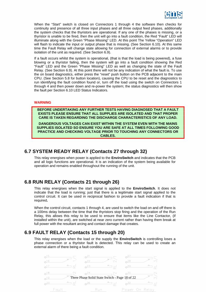
6.7 SYSTEM READY RELAY (Contacts 27 through 32)
This relay energises when power is applied to the EnviroSwitch and indicates that the PCB and all logic functions are operational. It is an indication of the system being available for operation and remains enabled throughout the running of the unit.
6.8 RUN RELAY (Contacts 21 through 26) This relay energises when the start signal is applied to the EnviroSwitch. It does not indicate that the load is running; just that there is a legitimate start signal applied to the control circuit. It can be used in reciprocal fashion to provide a fault indication if that is required.
When the control circuit, contacts 1 through 4, are used to switch the load on and off there is a 100ms delay between the time that the thyristors stop firing and the operation of the Run Relay, this allows this relay to be used to ensure that items like the Line Contactor, (if installed within the unit), are switched at near zero current rather than having them break at full power with the resultant arcing and contact damage that creates.
6.9 FAULT RELAY (Contacts 15 through 20) This relay energises when the load or the supply the EnviroSwitch is controlling loses a phase connection or a thyristor fault is detected. This relay can be used to create an external alarm of there being a fault condition.
Three Phase Solid State Switch - Page 19 of 22
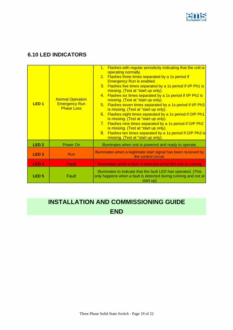
6.10 LED INDICATORS
LED 1 Normal Operation Emergency Run
Phase Loss
1. Flashes with regular periodicity indicating that the unit is operating normally.
2. Flashes three times separated by a 1s period if Emergency Run is enabled.
3. Flashes five times separated by a 1s period if I/P Ph1 is missing. (Test at “start up only).
4. Flashes six times separated by a 1s period if I/P Ph2 is missing. (Test at “start up only).
5. Flashes seven times separated by a 1s period if I/P Ph3 is missing. (Test at “start up only).
6. Flashes eight times separated by a 1s period if O/P Ph1 is missing. (Test at “start up only).
7. Flashes nine times separated by a 1s period if O/P Ph2 is missing. (Test at “start up only).
8. Flashes ten times separated by a 1s period if O/P Ph3 is missing. (Test at “start up only).
LED 2 Power On Illuminates when unit is powered and ready to operate.
LED 3 Run Illuminates when a legitimate start signal has been received by the control circuit.
LED 4 Fault Illuminates when a fault is detected whilst the unit is running
LED 5 Fault Illuminates to indicate that the fault LED has operated. (This
only happens when a fault is detected during running and not at start up)
INSTALLATION AND COMMISSIONING GUIDE END
Three Phase Solid State Switch - Page 20 of 22
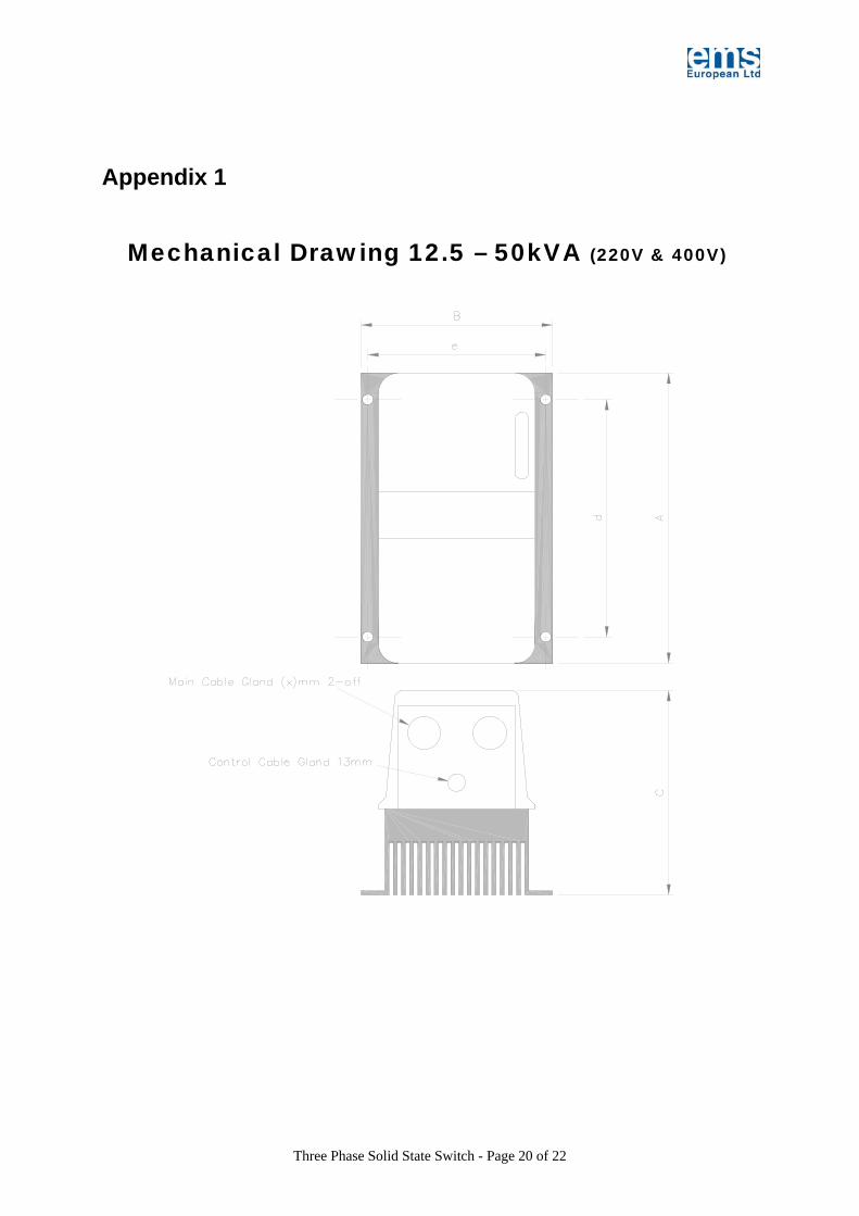
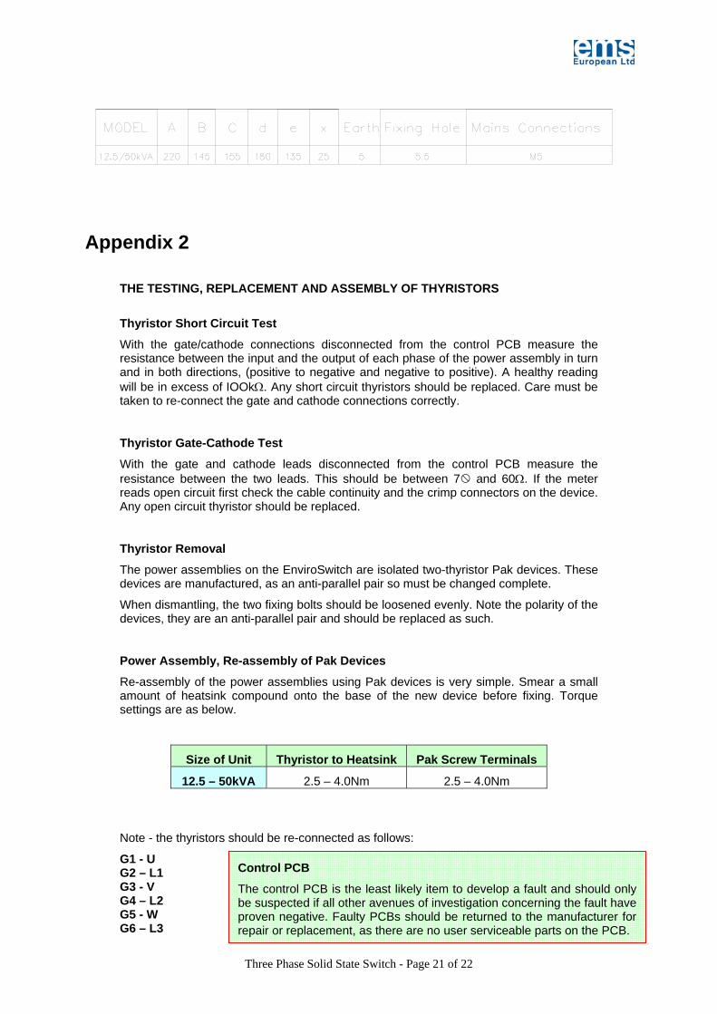
Appendix 1
Mechanical Drawing 12.5 – 50kVA (220V & 400V)
Three Phase Solid State Switch - Page 21 of 22
Appendix 2
THE TESTING, REPLACEMENT AND ASSEMBLY OF THYRISTORS
Thyristor Short Circuit Test
With the gate/cathode connections disconnected from the control PCB measure the resistance between the input and the output of each phase of the power assembly in turn and in both directions, (positive to negative and negative to positive). A healthy reading will be in excess of IOOkΩ. Any short circuit thyristors should be replaced. Care must be taken to re-connect the gate and cathode connections correctly.
Thyristor Gate-Cathode Test
With the gate and cathode leads disconnected from the control PCB measure the resistance between the two leads. This should be between 7 and 60Ω. If the meter reads open circuit first check the cable continuity and the crimp connectors on the device. Any open circuit thyristor should be replaced.
Thyristor Removal
The power assemblies on the EnviroSwitch are isolated two-thyristor Pak devices. These devices are manufactured, as an anti-parallel pair so must be changed complete.
When dismantling, the two fixing bolts should be loosened evenly. Note the polarity of the devices, they are an anti-parallel pair and should be replaced as such.
Power Assembly, Re-assembly of Pak Devices
Re-assembly of the power assemblies using Pak devices is very simple. Smear a small amount of heatsink compound onto the base of the new device before fixing. Torque settings are as below.
Size of Unit Thyristor to Heatsink Pak Screw Terminals
12.5 – 50kVA 2.5 – 4.0Nm 2.5 – 4.0Nm
Note - the thyristors should be re-connected as follows:
G1 - U G2 – L1 G3 - V G4 – L2 G5 - W G6 – L3
Control PCB
The control PCB is the least likely item to develop a fault and should only be suspected if all other avenues of investigation concerning the fault have proven negative. Faulty PCBs should be returned to the manufacturer for repair or replacement, as there are no user serviceable parts on the PCB.

Three Phase Solid State Switch - Page 22 of 22
THYRISTORS USED IN ENVIROSWITCH
PART No. THYRISTOR TYPE IXYS
AMPS @ Tcase 85oC QTY PER UNIT
TPPFCS - 12 MCC56-14io1 60 3
TPPFCS - 25 MCC95-14io1 116 3
TPPFCS - 50 MCC95-14io1 116 3
Appendix 3
GENERAL SPECIFICATION
MODEL CURRENT kVA @ 400V
WEIGHT kg
400-TPPFCS-12 23 12.5 3
400-TPPFCS-25 45 25 3
400-TPPFCS-50 75 50 4
The kVA ratings are all based on calculations scheduled with a capacitive load operating at a nominal Tambient of +20oC at sea level. All units should be selected based on the current rating of the load to which they are fitted.
Appendix 4
FAN SPECIFICATION FOR 25kVA AND 50kVA UNITS
Papst Part No. GD Rectifier Part No. EnviroStart Size Free Air Flow
Rate Physical Size
4600N/4650N 550010A/ 550010B 25kVA - 50kVA 160 m3/hour 120 mm