envs10003: log book interim submission s1_2014
DESCRIPTION
ÂTRANSCRIPT

CONSTRUCTING ENVIRONMENTS LOGBOOK - Thi Kieu Loan Lam

WEEK 1: COMPRESSION BLOCK TOWER CONSTRUCTION
The aim of this task was to build a tower as tall as possible using the least amount of MDF blocks. The tower had to accommodate a toy antelope, thus an entrance was required.
1. Our group decided to construct a tower that basically consisted of four walls. We started to build the 3 walls first and build the entrance later on. With little success, we decided to build around the entrance first and worked around that.
2. The walls consisted of a 1x2 structure. Where a single block was placed horizontally and was followed by double blocks placed vertically.
3. Building the entrance and the rest of tower resulted in consequences where the two different builds weren’t actually ‘connected’. Blocks were placed between the gaps as an attempt to combine the two separate builds.
4. The building itself was relatively quite short so half of the group decided to stack blocks in a fashionable way on top of the entrance structure to make it taller.
This was the gap was created as a resulted from building the entrance and the rest of the tower separately.
The entrance was a structure within itself, as it was able to hold a large amount of blocks to make the building taller.
1
3 2
4
Our group didn’t have a clear vision to constructing the tower, so the height of the tower was a result of random/experimental placement of the blocks.

STRUCTURE OF WALLS/BUILDING PATTERN STRUCTURE OF THE ENTRANCE
The blocks needed to be placed about roughly half way from the previous block to gradually build the arch.
If the blocks were placed too far apart from each other, the blocks would not enough room to compress against its structural member and would tumble over instead where more than half of the weight of the bricks is not supported.
This allowed the blocks to compressed amongst one another and remain stable.
The weight of the brick would tip over and would have caused the rest of the bricks to fall as well.
5 6

REMOVING BLOCKS FROM THE TOWER
Only the double blocks could be removed from the tower. Where the blocks were removed, the single block above it was able to bend with a dead load on top, with the support of the two single blocks beneath it.
Removing the single horizontal blocks would have compromised the structure as there would have been no support for double bricks above it, thus it will fall instead of compressing amongst the other bricks. The width of the vertical double blocks was not enough for it to compression without support from the bottom.
These are the two blocks that were removed.
These lines represent the block that was removed.
OBSERVATION OF OTHER TOWERS
Other groups decided to build circular towers. Blocks were placed with a gap between one another, which allowed the blocks to compress and remain stable. Whilst observing other towers, we had noticed that we used quite a lot of bricks considering the height of our tower (which was rather short). Not only did the circular towers were more stable but also used less blocks.
7 8
9

KNOWLEDGE MAP
WEEK 2: FORCE BALSA WOOD TOWER
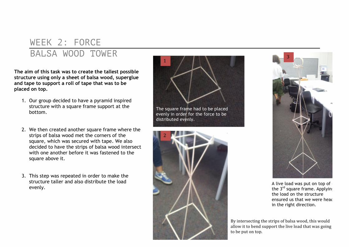
The aim of this task was to create the tallest possible structure using only a sheet of balsa wood, superglue and tape to support a roll of tape that was to be placed on top.
1. Our group decided to have a pyramid inspired structure with a square frame support at the bottom.
2. We then created another square frame where the strips of balsa wood met the corners of the square, which was secured with tape. We also decided to have the strips of balsa wood intersect with one another before it was fastened to the square above it.
3. This step was repeated in order to make the structure taller and also distribute the load evenly.
2
1 3
A live load was put on top of on the 3rd square frame. Applying the load on the structure ensured us that we were heading in the right direction.
The square frame had to be placed evenly in order for the force to be distributed evenly.
By intersecting the strips of balsa wood, this would allow it to bend support the live load that was going to be put on top.

By intersecting the strips of balsa wood before it was fastened, allowed us to create a structure that would ‘flex’ when a live load was placed on top. Repeating this step ensured that the force will be move in a consistent direction and gained height of the structure.
The intersection of strips was secured with superglue and tape. This was done to reinforce the strength of the structure.
BOTTOM SQUARE FRAME
With this particular structure, we had to ensure that each strip of balsa wood was cut evenly with the same width. If we had strips that varied in sizes, only parts of the structure would support/carry the direction of the force from the load.
4
5

LOAD TRIAL #1
The structure was a success. The flow/direction of the live load was distributed evenly through the structure hence why it was so important to keep the design of the structure consistent.
END RESULT
The higher we got, the smaller the square frame became. We managed to reach a fourth square, however then the roll of tape was placed on top the structure began to show signs of weakness.
Problems started to occur mainly in this area. The strips of the balsa wood were slightly thicker and inconsistent here.
When the load was applied, it didn’t sit properly on the top as the square frame was too small and slowly dragged the tower towards the floor.
6 7

By making a relatively small square frame prevented the strips of balsa wood to actually move at all when it intersected. This also disrupted the direction of the load.
THE EFFECT OF GRAVITY
BIRD’S EYE VIEW OF SQUARE FRAMES: A POSSIBLE SOLUTION
IDEAL: If the square frames were made with thinner strips of balsa wood and reducing only a few centimetres from the previous square for the next one, would have created a more stable, taller and even frame.
PROBLEM: There is a great contrast between the sizes of consecutive squares. The small squares limited our ability to go higher and support and hold the weight of the live load.
8 9
10

REFERENCES WEEK 1: Envs10003 (Producer), University of Melbourne, Parkville, viewed 8 March 2014, Basic structural forces retrieved from https://app.lms.unimelb.edu.au/bbcswebdav/courses/ENVS10003_2014_SM1/WEEK%2001/Basic%20Structural%20Forces%201.pdf Ching, F.D.K, Building Construction Illustrated, (Fourth Edition). Hoboken, NJ.:John Wiley & Sons, Inc.
WEEK 2: Envs10003 (Producer), University of Melbourne, Parkville, viewed 16 March 2014, W02 s1 Structural Systems retrieved from http://www.youtube.com/watch?v=l--JtPpI8uw&feature=youtu.be Envs10003 (Producer), University of Melbourne, Parkville, viewed 19 March 2014, W02 s2 Structural joint retrieved from http://www.youtube.com/watch?v=kxRdY0jSoJo&feature=youtu.be Ching, F.D.K, Building Construction Illustrated, (Fourth Edition). Hoboken, NJ.:John Wiley & Sons, Inc.