(ep) light liquid sampler - master controls inc
TRANSCRIPT

(EP) Light Liquid SamplerS Y S T E M S U P P O R T M A N U A L
Version 05102013


(EP)Light Liquid SamPLErinStruction & oPErating
manuaLVersion 05102013


(EP)Light Liquid SamPLEr tabLE of ContEntS
Page IY Z - M i l t o n R o y • 2 0 1 I v y l a n d R o a d • I v y l a n d , P a . • U S A • 1 8 9 7 4 • P : 2 8 1 . 3 6 2 . 6 5 0 0 • F : 2 8 1 . 3 6 2 . 6 5 1 3(EP)Light Liquid Sampler ver.05102013
Table of Contents ...............................................................................................................................I
Section 1: First Things To Know ....................................................................................................1 How to Use this Manual .................................................................................................................1 Typographic Conventions ..............................................................................................................1 Getting Help ...................................................................................................................................1 OperationSpecifications ................................................................................................................2 Theory of Operation .......................................................................................................................3 System Accessories ......................................................................................................................3
Section 2: System Installation.........................................................................................................5 Standard System Components Probe Mounted Pumps (PNR) .......................................................................................................5 Pneumatic Skid ..............................................................................................................................5 Hydraulic Skid ................................................................................................................................5 Skid Rear View-Five Way Cross ....................................................................................................6 System Flow Schematic Pneumatic Actuated Probe Mounted PNR-2P (EP) .....................................................................................................7 Hydraulic Actuated Probe Mounted PNR-2H (EP) ....................................................................................................8 Standard System Mounting Skids ..............................................................................................................................................9 Standard System Connections Pneumatic Actuated Skids Probe Mounted (PNR-2S-5P) ...................................................................................................10 Hydraulic Actuated Skids Probe Mounted (PNR-2S-5H) ...................................................................................................11
Section 3: Filling the Pre-Charge Vessel .....................................................................................15 Filling the Vessel ..........................................................................................................................15
Section 4: System Control & Electronics .....................................................................................18 Overview .......................................................................................................................................... Pneumatic Actuated Control Options “-0A-P” 24 VDC Control By Customer .........................................................................................18 “-0A-PL” 24 VDC Control By Customer w/ELM ...........................................................................19 Hydraulic Actuated Control Options “0A-H”24 VDC Control/120 VAC Hyd. By Customer ...................................................................20 “0A-H”24 VDC Control/120 VAC Hyd. By Customer w/ELM .......................................................21
Section 5: Programming for Proportional-to-Flow Operation ....................................................23 Setting Operator Input Parameters ..............................................................................................23 “-0” Control By Customer .............................................................................................................24

(EP)Light Liquid SamPLEr tabLE of ContEntS
Y Z - M i l t o n R o y • 2 0 1 I v y l a n d R o a d • I v y l a n d , P a . • U S A • 1 8 9 7 4 • P : 2 8 1 . 3 6 2 . 6 5 0 0 • F : 2 8 1 . 3 6 2 . 6 5 1 3Page II (EP)Light Liquid Sampler ver.05102013
Table of Contents ..............................................................................................................................II
Section 6: Mechanical System ......................................................................................................26 Sample Pumps and Discharge Valves ........................................................................................26 Accumulator Vessel .....................................................................................................................27 5-Way Cross ................................................................................................................................28 Actuation/Mixing System (Pneu) .................................................................................................29 Actuation/Mixing System (Hyd.) ..................................................................................................30
Section 7: System Operation.........................................................................................................31 Preparing The System for Operation ...........................................................................................31 Sample Pump Priming .................................................................................................................31 Product Line Test .........................................................................................................................31 Portable Sample Vessel Connection ...........................................................................................32
Section 8: System Maintenance ....................................................................................................35 Preventative Maintenance Schedule ...........................................................................................35 Recommended Maintenance Schedule .......................................................................................35 Monthly Inspection ....................................................................................................................35 Annual Inspection .....................................................................................................................35 Bi-Annual Inspection .................................................................................................................35 Recommended Spare Parts List ..................................................................................................35 Section 9: System Troubleshooting ..............................................................................................37 Pneumatic Systems: How to Use This Section .............................................................................................................37 For Additional Help ......................................................................................................................37 Step-by-Step Resolution ..............................................................................................................37 Actuation Gas Pressure Actuation Gas Pressure Troubleshooting Steps ..........................................................................37 Electrical Power Electrical Power Troubleshooting Steps ......................................................................................38 Sample Pulse Sample Pulse Troubleshooting Steps ..........................................................................................39 Pump Performance Pump Performance Troubleshooting Steps .................................................................................39 Pre-Charge/Product Accumulator Pre-Charge/Product Accumulator Troubleshooting Steps ...........................................................40 Hydraulic Systems How to Use This Section .............................................................................................................41 For Additional Help ......................................................................................................................41 Step-by-Step Resolution ..............................................................................................................41 Electrical Power Electrical Power Troubleshooting Steps ......................................................................................42 Sample Pulse Troubleshooting Steps ..........................................................................................42 Hydraulic Power Hydraulic Power Troubleshooting Steps ......................................................................................43

(EP)Light Liquid SamPLEr tabLE of ContEntS
Page IIIY Z - M i l t o n R o y • 2 0 1 I v y l a n d R o a d • I v y l a n d , P a . • U S A • 1 8 9 7 4 • P : 2 8 1 . 3 6 2 . 6 5 0 0 • F : 2 8 1 . 3 6 2 . 6 5 1 3(EP)Light Liquid Sampler ver.05102013
Table of Contents .............................................................................................................................III
Appendix A: Illustrations ...............................................................................................................45 PNR-2P (EP) Sample Pump Assembled .....................................................................................45 PNR-2H (EP) Sample Pump Assembled .....................................................................................46 5-Way Cross Assembly ................................................................................................................47 Pre-Charge System .....................................................................................................................48Pneumatic Product Accumulator Vessel Product Accumulator Vessel ........................................................................................................49 Mixing System-Accumulator ........................................................................................................50 Mixing System .............................................................................................................................51Hydraulic Product Accumulator Vessel Product Accumulator Vessel ........................................................................................................52 Mixing System-Accumulator ........................................................................................................53 Mixing System .............................................................................................................................54 Hydraulic Power Pack .................................................................................................................55 Electrical Wiring Hydraulic Power Pack/Test Switch ...................................................................56
Electronic Level Monitor Addendum (ELM) .....................................................................................Product Description .............................................................................................................................1ELMSpecificaltions .............................................................................................................................2ELM Accuracy......................................................................................................................................3ELM Theory of Operation ....................................................................................................................3ELM Wiring Control Document ............................................................................................................4ELM Barrier Information ......................................................................................................................5ELM System Check .............................................................................................................................6ELM Maintenance................................................................................................................................6ELM AdjustmentsCalibration ...........................................................................................................................................8To Set ZERO .......................................................................................................................................8To Set SPAN ........................................................................................................................................8

(EP)Light Liquid SamPLEr tabLE of ContEntS
Y Z - M i l t o n R o y • 2 0 1 I v y l a n d R o a d • I v y l a n d , P a . • U S A • 1 8 9 7 4 • P : 2 8 1 . 3 6 2 . 6 5 0 0 • F : 2 8 1 . 3 6 2 . 6 5 1 3Page IV (EP)Light Liquid Sampler ver.05102013
Notes

Section 1: FirSt thingS to Know About (eP)Light Liquid SAmPLerS
Page 1Y Z - M i l t o n R o y • 2 0 1 I v y l a n d R o a d • I v y l a n d , P a . • U S A • 1 8 9 7 4 • P : 2 8 1 . 3 6 2 . 6 5 0 0 • F : 2 8 1 . 3 6 2 . 6 5 1 3
(EP)Light Liquid Sampler ver. 05102013
How to Use this ManualThe (EP)Light Liquid Sampler Operations Manual is a step-by-step guide containing the procedures needed to work with the Light Liquid Sampler System.
The (EP)Light Liquid Sampler Series of samplers implement the most advanced technology available in the industry. It is recommended that the technicians working with the (EP)Light Liquid Sampler Systems study the manual prior to initiating work on the system for the first time.
Typographic ConventionsTo aide in readability, this manual uses several typographic conventions. References to illustrations, photographs, and other related content will appear in italicized text along with the location of where to find the item in the manual. Digital versions of the manual, are available in Adobe Acrobat™ PDF format.
Measurement units are listed in italic parenthesis text following their US standard equivalent. As an ex-ample, for defining a distance, 15’ (4.5 meters), is how the text will appear throughout the manual.
Items that require action, for example the pressing of a key for programming the controller, will feature the action item in sentence case Bold Text followed in normal text by the item such as, the Up Arrow key or Main Power switch.
™ Adobe Acrobat & Acrobat Reader are trademarks of Adobe Systems, Inc.
Getting HelpThis manual provides solutions to typical questions about the Light Liquid Sampler system. If the an-swer can not be found within this manual, contact YZ Systems at: T: 1.281.362.6500 T: 1.800.653.9435 F: 1.281.362.6513 Em: [email protected]
When calling, have this manual close at hand. Whether calling or writing, please include in your com-munique the following information:
• The serial number of the (EP)Light Liquid Sampler System and the version number of this manual. The serial number is located on the system skid or enclosure. The version number of this manual is located at the bottom of each page.
• A description of the problem and, if applicable the
actions of the technical personnel when the problem occurred.

Section 1: FirSt thingS to Know About (eP)Light Liquid SAmPLerS
Y Z - M i l t o n R o y • 2 0 1 I v y l a n d R o a d • I v y l a n d , P a . • U S A • 1 8 9 7 4 • P : 2 8 1 . 3 6 2 . 6 5 0 0 • F : 2 8 1 . 3 6 2 . 6 5 1 3Page 2 (EP)Light Liquid Sampler ver.05102013
Operation SpecificationsMaximum Output: Std. 3/8” Plunger 6.8 gallons/day (25.3 liters/day)Maximum Operating Pressure: 1,800 psig (124 Bar (g)Pump Displacement: Std. 3/8” Plunger .25 - 1.8 cc/StrokeOperating Temp Range: 0 to 140 degrees F. (-17°C to 60°C)Power Supply Options: Pneumatic 24 VDC Hydraulic 120 VAC @ 20 AMP 24 VDC Signal Actuation Gas; 100 psi Instrument Quality Gas
Note: at temperatures below 32º F (0º C), condi-tioning of the actuation gas supply may be required. Where the actuation gas supply has a high water con-tent and/or a low hydrocarbon dew point, additional actuation gas filtration or heating of the actuation gas supply may be necessary. Bottled nitrogen can also be used during cold operating conditions to avoid con-densation in the actuation gas supply line. In addition, operation at extreme temperatures may affect system performance. To enhance the performance of this system, adequate heat should be provided to maintain an operating environment above 30° F (-1º C).
* Refer to Manual Section 4, System Control Options

Section 1: FirSt thingS to Know About (eP)Light Liquid SAmPLerS
Page 3Y Z - M i l t o n R o y • 2 0 1 I v y l a n d R o a d • I v y l a n d , P a . • U S A • 1 8 9 7 4 • P : 2 8 1 . 3 6 2 . 6 5 0 0 • F : 2 8 1 . 3 6 2 . 6 5 1 3
(EP)Light Liquid Sampler ver. 05102013
Theory of OperationThe Light Liquid sampling systems are designed to sample light liquid hydrocarbons. Thousands of individual samples are captured and com-bined to develop a representative, composite sample of the flowing pipeline.
Operation of the sampling system centers around the following primary components: the Sample Pump, the Product Accumulator Vessel, the Precharge Gas Vessel, and the Electronic Control System. All equipment, except probe mounted Sample Pumps are mounted on a steel skid. These components are shown in the diagrams on the following pages.
The sampling system operates on a simple concept. When the system receives a proper flow signal (by others), the solenoid valve or Hy-draulic Power Pack is energized. Energizing the solenoid valve, or Hydraulic Power Pack allows a pressurized pulse into the actuation cylinder of the sample pump, which in turn causes the pump to stroke. When the pump strokes, a small sample is displaced into the product accu-mulator vessel. Once the solenoid valve, or Hy-draulic Power Pack is de-energized, the sample pump plunger returns to its normal position. This action allows a new sample bite to be captured in the pump.
The purpose of the YZ light liquid hydrocarbon sampling system is to capture and maintain a representative liquid sample of the pipeline product. The sampled product is maintained in a liquid phase by the product accumulator vessel’s free floating piston and the precharge gas system. In order for the system to function properly, pipeline product must be single phase, liquid product.
By properly adjusting both the sample size and the sample frequency, the sample vessel will fill to 80% capacity at the end of the sample period. Once the sample period is complete, the product within the sample receiver is thoroughly mixed using the power mixer. A representative sample can then be removed from the product accu-mulator vessel using the YZ DuraSite, a DOT approved constant pressure sample vessel, refer to page 32-33.
After removing the remainder of the product from the accumulator vessel, the system is then ready for a new sample period.
System Accessories• DuraSite, portable DOT approved constant pres-
sure sample vessels. Available in 150, 300, 500, 800, and 1000 cc sizes.
• KK-1, KK-2, & KK-3: carrying cases for DuraSites that meet DOT requirements for transporting por-table sample vessels.
• 1/4” stainless steel tubing Dielectric Isolator Union. These should be installed in every tubing line that attaches the sampler to the pipeline in any manner. For example the supply gas, product connection to the system, and differential pressure switch connections, (P/N A1-0182).
A complete line of sampling accessories ranging from sample probes to sample vessels is available through YZ - Milton Roy. Please contact your local represen-tative or YZ - Milton Roy toll free at 800.344.5399. For technical support call 800.653.9435.

Section 1: FirSt thingS to Know About (eP)Light Liquid SAmPLerS
Y Z - M i l t o n R o y • 2 0 1 I v y l a n d R o a d • I v y l a n d , P a . • U S A • 1 8 9 7 4 • P : 2 8 1 . 3 6 2 . 6 5 0 0 • F : 2 8 1 . 3 6 2 . 6 5 1 3Page 4 (EP)Light Liquid Sampler ver.05102013
Notes

SECTION 2: SYSTEM INSTALLATION
Page 5Y Z - M i l t o n R o y • 2 0 1 I v y l a n d R o a d • I v y l a n d , P a . • U S A • 1 8 9 7 4 • P : 2 8 1 . 3 6 2 . 6 5 0 0 • F : 2 8 1 . 3 6 2 . 6 5 1 3
(EP)Light Liquid Sampler ver.05102013
Standard Probe Mounted Pump (PNR) System ComponentsStandard primary components of the Probe Mounted Pump System (PNR-2) include the following:• Sample Pump, fi gure 1. Pneumatically or Hydraulically actuated PNR-2
probe mounted Sample Pump.
• System Skid, fi gure 2 (Pneumatic), fi gure 3 (Hy-draulic), & fi gure 4 (Both). Houses the Accumulator Vessel, Pre-charge Vessel, and System Electronics Enclosure.
• Product Accumulator Vessel, fi gure 2 (Pneumatic
Skid), fi gure 3 (Hydraulic Skid), fi gure 4 (Both), 5 Gallon (18.93 Liters).
• Pre-Charge Vessel, fi gure 2 (Pneumatic Skid), fi gure 3 (Hydraulic Skid), fi gure 4 (Both).
fi gure 1
fi gure 3fi gure 2 HydraulicPneumatic

SECTION 2: SYSTEM INSTALLATION
Y Z - M i l t o n R o y • 2 0 1 I v y l a n d R o a d • I v y l a n d , P a . • U S A • 1 8 9 7 4 • P : 2 8 1 . 3 6 2 . 6 5 0 0 • F : 2 8 1 . 3 6 2 . 6 5 1 3Page 6 (EP)Light Liquid Sampler ver.05102013
• Five-Way Cross, fi gure 4, mounts the Pressure Gage, Relief Valve, Product Isolation, and Product Removal Valves.
fi gure 4
Standard Probe Mounted Pump (PNR) System Components

SECTION 2: SYSTEM INSTALLATION
Page 7Y Z - M i l t o n R o y • 2 0 1 I v y l a n d R o a d • I v y l a n d , P a . • U S A • 1 8 9 7 4 • P : 2 8 1 . 3 6 2 . 6 5 0 0 • F : 2 8 1 . 3 6 2 . 6 5 1 3
(EP)Light Liquid Sampler ver.05102013
System Pneumatic Actuated Flow Schematic Probe Mounted PNR-2P (EP)
fi gure 5

SECTION 2: SYSTEM INSTALLATION
Y Z - M i l t o n R o y • 2 0 1 I v y l a n d R o a d • I v y l a n d , P a . • U S A • 1 8 9 7 4 • P : 2 8 1 . 3 6 2 . 6 5 0 0 • F : 2 8 1 . 3 6 2 . 6 5 1 3Page 8 (EP)Light Liquid Sampler ver.05102013
System Hydraulic Actuated Flow Schematic Probe Mounted PNR-2H (EP) fi gure 6
SECTION 2: SYSTEM INSTALLATION
Page 9Y Z - M i l t o n R o y • 2 0 1 I v y l a n d R o a d • I v y l a n d , P a . • U S A • 1 8 9 7 4 • P : 2 8 1 . 3 6 2 . 6 5 0 0 • F : 2 8 1 . 3 6 2 . 6 5 1 3
(EP)Light Liquid Sampler ver.05102013
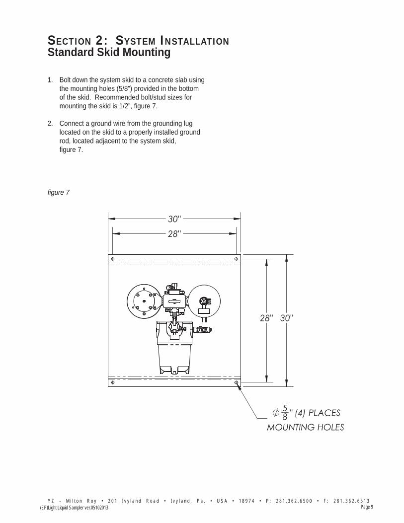
Standard Skid Mounting
1. Bolt down the system skid to a concrete slab using the mounting holes (5/8”) provided in the bottom of the skid. Recommended bolt/stud sizes for mounting the skid is 1/2”, fi gure 7.
2. Connect a ground wire from the grounding lug located on the skid to a properly installed ground rod, located adjacent to the system skid,
fi gure 7.
fi gure 7
SECTION 2: SYSTEM INSTALLATION
Y Z - M i l t o n R o y • 2 0 1 I v y l a n d R o a d • I v y l a n d , P a . • U S A • 1 8 9 7 4 • P : 2 8 1 . 3 6 2 . 6 5 0 0 • F : 2 8 1 . 3 6 2 . 6 5 1 3Page 10 (EP)Light Liquid Sampler ver.05102013
fi gure 13
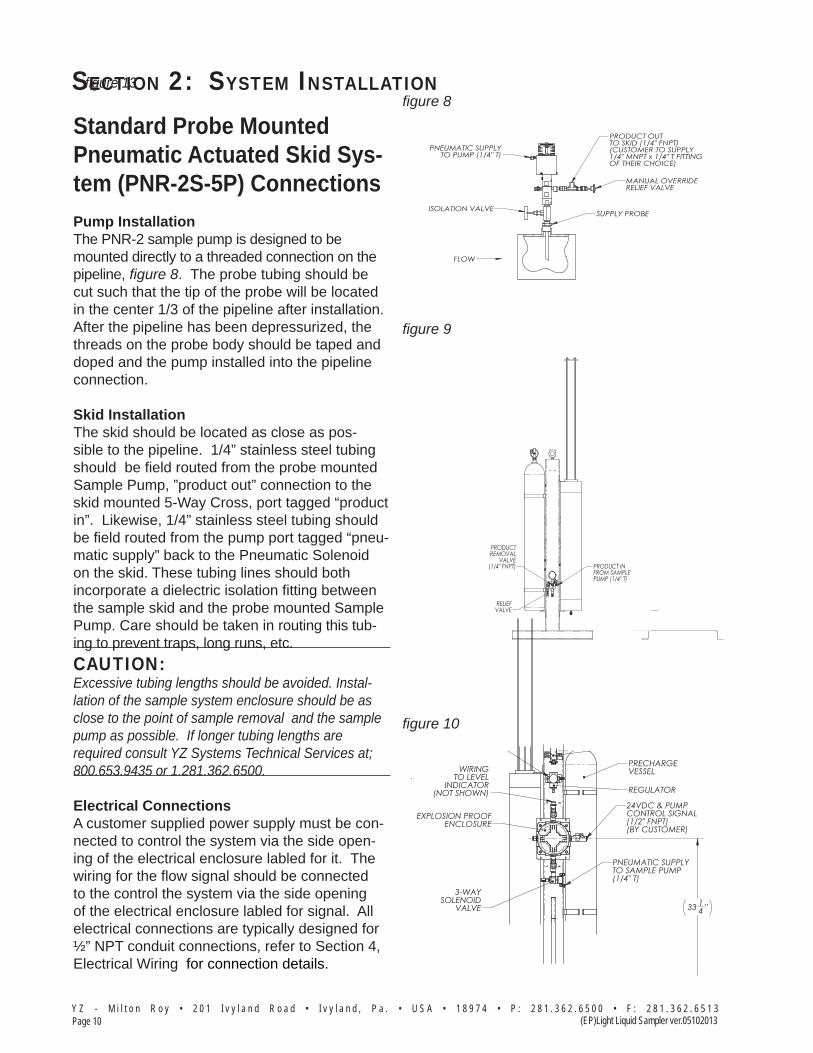
Standard Probe Mounted Pneumatic Actuated Skid Sys-tem (PNR-2S-5P) ConnectionsPump InstallationThe PNR-2 sample pump is designed to be mounted directly to a threaded connection on the pipeline, fi gure 8. The probe tubing should be cut such that the tip of the probe will be located in the center 1/3 of the pipeline after installation. After the pipeline has been depressurized, the threads on the probe body should be taped and doped and the pump installed into the pipeline connection.
Skid InstallationThe skid should be located as close as pos-sible to the pipeline. 1/4” stainless steel tubing should be fi eld routed from the probe mounted Sample Pump, ”product out” connection to the skid mounted 5-Way Cross, port tagged “product in”. Likewise, 1/4” stainless steel tubing should be fi eld routed from the pump port tagged “pneu-matic supply” back to the Pneumatic Solenoid on the skid. These tubing lines should both incorporate a dielectric isolation fi tting between the sample skid and the probe mounted Sample Pump. Care should be taken in routing this tub-ing to prevent traps, long runs, etc.CAUTION: Excessive tubing lengths should be avoided. Instal-lation of the sample system enclosure should be as close to the point of sample removal and the sample pump as possible. If longer tubing lengths are required consult YZ Systems Technical Services at; 800.653.9435 or 1.281.362.6500.
Electrical ConnectionsA customer supplied power supply must be con-nected to control the system via the side open-ing of the electrical enclosure labled for it. The wiring for the fl ow signal should be connected to the control the system via the side opening of the electrical enclosure labled for signal. All electrical connections are typically designed for ½” NPT conduit connections, refer to Section 4, Electrical Wiring for connection details.
fi gure 8
fi gure 10
fi gure 9
3Q-0837.pdf ()

SECTION 2: SYSTEM INSTALLATION
Page 11Y Z - M i l t o n R o y • 2 0 1 I v y l a n d R o a d • I v y l a n d , P a . • U S A • 1 8 9 7 4 • P : 2 8 1 . 3 6 2 . 6 5 0 0 • F : 2 8 1 . 3 6 2 . 6 5 1 3
(EP)Light Liquid Sampler ver.05102013
Standard Probe Mounted Hydraulic Actuated Skid Sys-tem (PNR-2S-5H) ConnectionsPump InstallationThe PNR-2 sample pump is designed to be mounted directly to a threaded connection on the pipeline, fi gure 11. The probe tubing should be cut such that the tip of the probe will be located in the center 1/3 of the pipeline after installation. After the pipeline has been depressurized, the threads on the probe body should be taped and doped and the pump installed into the pipeline connection.
System Skid InstallationThe system skid portion of the sampler should be located as close as possible to the sample pump. 1/4” stainless steel tubing should be fi eld routed from the Sample Pump discharge check (product out), fi gure 11, to the Five-Way Cross connection (product in), fi gure 12 (front) on the Skid. Care should be taken in routing tubing to prevent traps, long runs, etc.
1/4” - 3/8” stainless steel tubing should also be fi eld routed from the connection on the Sample Pump labeled hydraulic supply (from skid), fi gure 13, to the hydraulic supply to pump connection on the system Skid, fi gure 13 (rear). Additional-ly1/4” - 3/8” stainless steel tubing should also be fi eld routed from the connection on the Sample Pump labeled hydraulic return (from skid), fi gure 13, to the hydraulic return from pump connection on the system skid, fi gure 13(rear).
CAUTION: Excessive tubing lengths should be avoided. Installa-tion of the sample system Skid should be as close to the point of sample removal and the sample pump as possible. If longer tubing lengths are required consult YZ Systems Technical Services at; 800.653.9435 or 1.281.362.6500.
fi gure 11
fi gure 12
fi gure 13

SECTION 2: SYSTEM INSTALLATION
Y Z - M i l t o n R o y • 2 0 1 I v y l a n d R o a d • I v y l a n d , P a . • U S A • 1 8 9 7 4 • P : 2 8 1 . 3 6 2 . 6 5 0 0 • F : 2 8 1 . 3 6 2 . 6 5 1 3Page 12 (EP)Light Liquid Sampler ver.05102013
Standard Probe Mounted Hydraulic Actuated Skid Sys-tem (PNR-2S-5H) Connections
Electrical Connections120 VAC, 60 Hz electrical power, and the fl ow signal should be connected to the left side open-ing for the electrical Skid fi gure 13 (rear).
Pump Sample SizeThe sample size of the PNR-2 is adjustable. The sample grab size of the pump is adjusted by loosening the lock/seal nut on top of the pump and turning the volume adjustment screw in to decrease the sample volume or out to increase the sample volume. Once the new sample size has been set, the lock/seal nut should be retight-ened. Refere to section 2 Page 13.
Hydraulic Power Pack BreatherRemove the 3/8” NPT plug located in the top of the power pack reservoir. Install the breather provided with the skid.
Hydraulic Pump Line PurgingDuring this process, check the fl uid level in the hydraulic oil reservoir frequently to assure that you do not run low on fl uid. Slightly loosen the return connection tubing connection on the System Skid. When the Hydraulic Power Pack is actuated in this mode air will escape at this con-nection. Verify that the electrical Mode Switch is in the Mix Mode, and the manual Diverter Valve is set to Sample. Now use the electrical Test Switch to actuate the Hydraulic Power Pack. Hold in the Test position until you get hydraulic fl uid at the hydraulic return connection. As soon as you get fl uid at this connection, release the Test switch, and tighten the connection.
Vent
fi gure 14
SECTION 2: SYSTEM INSTALLATION
Page 13Y Z - M i l t o n R o y • 2 0 1 I v y l a n d R o a d • I v y l a n d , P a . • U S A • 1 8 9 7 4 • P : 2 8 1 . 3 6 2 . 6 5 0 0 • F : 2 8 1 . 3 6 2 . 6 5 1 3
(EP)Light Liquid Sampler ver.05102013
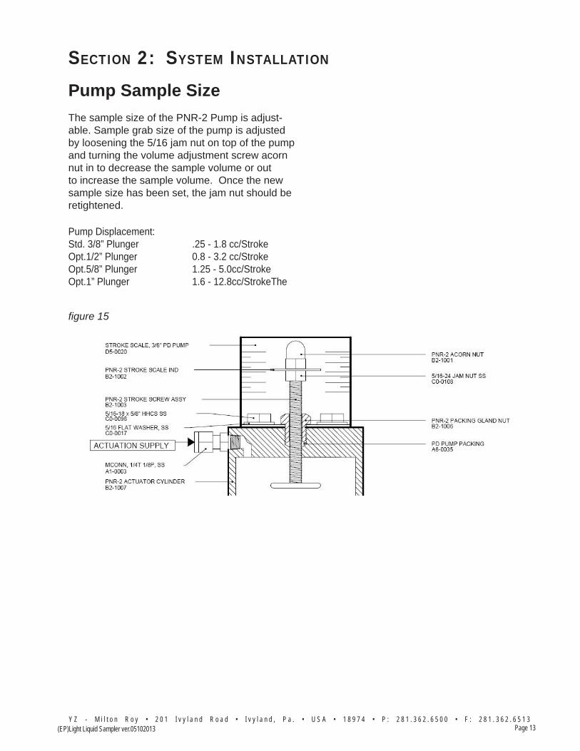
Pump Sample SizeThe sample size of the PNR-2 Pump is adjust-able. Sample grab size of the pump is adjusted by loosening the 5/16 jam nut on top of the pump and turning the volume adjustment screw acorn nut in to decrease the sample volume or out to increase the sample volume. Once the new sample size has been set, the jam nut should be retightened.
Pump Displacement: Std. 3/8” Plunger .25 - 1.8 cc/StrokeOpt.1/2” Plunger 0.8 - 3.2 cc/StrokeOpt.5/8” Plunger 1.25 - 5.0cc/StrokeOpt.1” Plunger 1.6 - 12.8cc/StrokeThe
fi gure 15

SECTION 2: SYSTEM INSTALLATION
Y Z - M i l t o n R o y • 2 0 1 I v y l a n d R o a d • I v y l a n d , P a . • U S A • 1 8 9 7 4 • P : 2 8 1 . 3 6 2 . 6 5 0 0 • F : 2 8 1 . 3 6 2 . 6 5 1 3Page 14 (EP)Light Liquid Sampler ver.05102013
Notes

Section 3: Filling the Pre-charge VeSSel
Page 15Y Z - M i l t o n R o y • 2 0 1 I v y l a n d R o a d • I v y l a n d , P a . • U S A • 1 8 9 7 4 • P : 2 8 1 . 3 6 2 . 6 5 0 0 • F : 2 8 1 . 3 6 2 . 6 5 1 3
(EP)Light Liquid Sampler ver.05102013
The purpose of the precharge system is to keep the sampled product in a liquid phase. This is accomplished by maintaining a precharge pres-sure on top of the accumulator vessel piston. The precharge vessel provides additional vol-ume to the precharge system, which minimizes the pressure increase within the product accu-mulator as it fills.
Prior to placing the sampler into service, it is necessary that the precharge system be charged to a pressure at least 100 psi greater than the product vapor pressure. For example, if a product with a vapor pressure of 300 psi is being sampled, a precharge pressure of 400 psi would be required. Servicing the precharge vessel is done using the isolation valve located on top of the precharge vessel. Please note that the valve isolates the precharge system from the atmo-sphere, and does not separate the precharge vessel from the accumulator vessel. Also, the precharge vessel is shipped with 10 psi of blan-ket pressure. Normally this Pre-Charge vessel should only need to be filled one time at the installation of the sampler system, as the gas is not consumed in the sampling process.
CAUTION: Take necessary precautions when working with Nitro-gen Vessels, as the high pressure contained within is dangerous Additionally, all personnel should wear protective clothing, and use equipment as recom-mended by the manufacturer during this time. If you are uncertain about any aspect of the Nitrogen Vessel itself, you should contact the manufacturer of your Vessel prior to proceeding.
Filling the Vessel1. Connect the precharge gas source (normally
nitrogen) to the isolation valve 1/4” NPT connection located on top of the precharge vessel.
2. Open the isolation valve.
3. Fill the precharge vessel with gas until the pressure in the vessel is 100 to 150 psi above the vapor pressure of the product to be sampled.
4. Once the vessel is filled, close the isolation valve and remove the precharge gas source.
5. Leak test all connections between the precharge vessel and the product accumu- lator vessel.
6. Continue through the remaining procedures in this manual.

Section 3: Filling the Pre-charge VeSSel
Y Z - M i l t o n R o y • 2 0 1 I v y l a n d R o a d • I v y l a n d , P a . • U S A • 1 8 9 7 4 • P : 2 8 1 . 3 6 2 . 6 5 0 0 • F : 2 8 1 . 3 6 2 . 6 5 1 3Page 16 (EP)Light Liquid Sampler ver.05102013
Notes

Page 17 (EP) Light Liquid Sampler Ver. 05102013
Section 4: SyStem control & electronicS
Y Z - M i l t o n R o y • 2 0 1 I v y l a n d R o a d • I v y l a n d , P a . • U S A • 1 8 9 7 4 • P : 2 8 1 . 3 6 2 . 6 5 0 0 • F : 2 8 1 . 3 6 2 . 6 5 1 3
Section 4: SyStem control & electronicS
OverviewThe electronic control package provided with your sampling system consist of a simple sole-noid or Hydraulic Powerpack which interfaces with a 24 VDC pulse from an outside control system to operate it, The control system must send a mimimum 3 second actuation pulse to the sample pump for pneumatic operation, or a 5 sec.pulse for Hydraulic operation. This allows sufficient time to stroke the sample pump and retrieve a single sample.
SAFETY NOTES• Always use extreme care when performing mainte-
nance on Sampling Systems. Always take neces-sary measures to assure that electrical classification in the area is considered, before, and during all repairs, and that necessary steps are taken to main-tain proper electrical procedures for the classifica-tion of the area.
All electronic controls are housed in explosion proof enclosures and are rated for use in Class I, Division 1, Groups C and D hazardous locations, or are Intrinsically Safe for installation in Class I, Division 1, Groups C and D hazardous locations.
By properly adjusting both the sample size and the sample frequency, the sample vessel will fill to 80% capacity at the end of the sample period.
Refer to apropriate control option wiring informa-tion on the following pages.

Page 18 (EP) Light Liquid Sampler Ver. 05102013
Section 4: SyStem control & electronicS
Y Z - M i l t o n R o y • 2 0 1 I v y l a n d R o a d • I v y l a n d , P a . • U S A • 1 8 9 7 4 • P : 2 8 1 . 3 6 2 . 6 5 0 0 • F : 2 8 1 . 3 6 2 . 6 5 1 3
Pneumatic Actuated “- 0A-P” Control OptionThe electronic control package provided this sampling system consist of a simple solenoid which interfaces with an outside customer supplied power supply/control system to operate it. The control system must send a mimimum 3 second 24 VDC actuation pulse to the solenoid connections at ter-minals 5 and 6. This 3 second duration allows sufficient time for the solenoid to actuate the sample pump and retrieve a single sample.
Proper programing of the customer supplied control unit should allow the sample vessel to fill to 80% capacity at the end of the sample period.
figure 16
3E-0243.dwg ()
2 of 3

Page 19 (EP) Light Liquid Sampler Ver. 05102013
Section 4: SyStem control & electronicS
Y Z - M i l t o n R o y • 2 0 1 I v y l a n d R o a d • I v y l a n d , P a . • U S A • 1 8 9 7 4 • P : 2 8 1 . 3 6 2 . 6 5 0 0 • F : 2 8 1 . 3 6 2 . 6 5 1 3
Pneumatic Actuated “- 0A-PL” Control OptionThe electronic control package provided this sampling system consist of a simple solenoid which interfaces with an outside customer supplied power supply/control system to operate it. The control system must send a mimimum 3 second 24 VDC actuation pulse to the solenoid connections at ter-minals 5 and 6. This 3 second duration allows sufficient time for the solenoid to actuate the sample pump and retrieve a single sample.
Proper programing of the customer supplied control unit should allow the sample vessel to fill to 80% capacity at the end of the sample period.
This control option also includs an electronic level monitoring system for the 5 gallon vessel. It must be suuplied with a 24 VDC power source at terminals 9 and 10, and returns a 4-20mA level monitor-ing signal via terminals 7 and 8.figure 17

Page 20 (EP) Light Liquid Sampler Ver. 05102013
Section 4: SyStem control & electronicS
Y Z - M i l t o n R o y • 2 0 1 I v y l a n d R o a d • I v y l a n d , P a . • U S A • 1 8 9 7 4 • P : 2 8 1 . 3 6 2 . 6 5 0 0 • F : 2 8 1 . 3 6 2 . 6 5 1 3
Hydraulic Actuated “- 0A-H” Control Option
The electronic control package provided with this sampling system consists of a solid state Relay. The converts the 24 VDC pulse from your flow monitoring interface into a 5 second 120 VAC volt-age output to the hydraulic power pack, everytime a contact closure occurs. This 5 second duration allows sufficient time to actuate the sample pump and retrieve a single sample.
SAFETY NOTES• Always use extreme care when performing maintenance on Sampling Systems. Always take necessary mea-
sures to assure that electrical classification in the area is considered, before, and during all repairs, and that necessary steps are taken to maintain proper electrical procedures for the classification of the area.
The control package requires you to provide 120 VAC at terminals 1, 2 and 3. You are also required to provide 24 VDC pulse from your flow monitoring interface to terminals 5 and 6, in order to stroke the pump. All electronics are housed in explosion proof enclosures and are rated for use in Class I, Division 1, Groups C and D hazardous, locations.
This control option also includes an electronic level monitoring system for the 5 gallon vessel. It must be suuplied with a 24 VDC power source at terminals 9 and 10, and returns a 4-20mA level monitoring signal via terminals 7 and 8.
figure 18 3E-0245.dwg ()
2 of 3

Page 21 (EP) Light Liquid Sampler Ver. 05102013
Section 4: SyStem control & electronicS
Y Z - M i l t o n R o y • 2 0 1 I v y l a n d R o a d • I v y l a n d , P a . • U S A • 1 8 9 7 4 • P : 2 8 1 . 3 6 2 . 6 5 0 0 • F : 2 8 1 . 3 6 2 . 6 5 1 3
Hydraulic Actuated “- 0A-HL” Control Option
The electronic control package provided with this sampling system consists of a solid state Relay. The converts the 24 VDC pulse from your flow monitoring interface into a 5 second 120 VAC volt-age output to the hydraulic power pack, everytime a contact closure occurs. This 5 second duration allows sufficient time to actuate the sample pump and retrieve a single sample.
SAFETY NOTES• Always use extreme care when performing maintenance on Sampling Systems. Always take necessary mea-
sures to assure that electrical classification in the area is considered, before, and during all repairs, and that necessary steps are taken to maintain proper electrical procedures for the classification of the area.
The control package requires you to provide 120 VAC at terminals 1, 2 and 3. You are also required to provide 24 VDC pulse from your flow monitoring interface to terminals 5 and 6, in order to stroke the pump. All electronics are housed in explosion proof enclosures and are rated for use in Class I, Division 1, Groups C and D hazardous, locations.
figure 19
This control option also includes an electronic level monitoring system for the 5 gallon vessel. It must be suuplied with a 24 VDC power source at terminals 9 and 10, and returns a 4-20mA level monitoring signal via terminals 7 and 8.

Page 22 (EP) Light Liquid Sampler Ver. 05102013
Section 4: SyStem control & electronicS
Y Z - M i l t o n R o y • 2 0 1 I v y l a n d R o a d • I v y l a n d , P a . • U S A • 1 8 9 7 4 • P : 2 8 1 . 3 6 2 . 6 5 0 0 • F : 2 8 1 . 3 6 2 . 6 5 1 3
Notes

Section 5: Programming for oPeration
Page 23Y Z - M i l t o n R o y • 2 0 1 I v y l a n d R o a d • I v y l a n d , P a . • U S A • 1 8 9 7 4 • P : 2 8 1 . 3 6 2 . 6 5 0 0 • F : 2 8 1 . 3 6 2 . 6 5 1 3
(EP)Light Liquid Sampler ver.05102013
The Light Liquid sampling systems are designed to sample light liquid hydrocarbons. Thousands of individual samples are captured and com-bined to develop a representative, composite sample of the flowing pipeline.
Operation of the sampling system centers around the following primary components: the Sample Pump, the Product Accumulator Vessel, the Precharge Gas Vessel, and the Electronic Control System. The following pages provide specific details for setting up your system for operation.
The sampling system operates on a simple concept. When the system receives a proper flow signal (by others), the electronic control unit energizes either a solenoid valve, or a Hydrau-lic Power Pack. Energizing the solenoid valve, or Hydraulic Power Pack allows a pressurized pulse into the actuation cylinder of the sample pump, which in turn causes the pump to stroke. When the pump strokes, a small sample is displaced into the product accumulator vessel. Once the solenoid valve, or Hydraulic Power Pack is de-energized, the sample pump plunger returns to its normal position. This action allows a new sample into the pump.
The purpose of the YZ light liquid hydrocarbon sampling system is to capture and maintain a representative liquid sample of the pipeline product. The sampled product is maintained in a liquid phase by the product accumulator vessel’s free floating piston and the precharge gas system. In order for the system to function properly, pipeline product must be single phase, liquid product.
By properly adjusting both the sample size and the sample frequency, the sample vessel will fill to 80% capacity at the end of the sample period.
Setting Operator Input Parameters

Section 5: Programming for oPeration
Y Z - M i l t o n R o y • 2 0 1 I v y l a n d R o a d • I v y l a n d , P a . • U S A • 1 8 9 7 4 • P : 2 8 1 . 3 6 2 . 6 5 0 0 • F : 2 8 1 . 3 6 2 . 6 5 1 3Page 24 (EP)Light Liquid Sampler ver. 05102013
Setting Operator Input Parameters “-0” Control Options
The electronic control package for this sampling system is completely customer provided. The system is provided with a Solenoid or Hydraulic Power Pack to actuate the sample pump which requires a voltage pulsed signal with a dwell time of 3-5 seconds to properly actuate the sample pump. This 3-5 second duration allows sufficient time to stroke the sample pump and retrieve a single sample.
SAFETY NOTES• Always use extreme care when performing maintenance on Sampling Systems. Always take necessary mea-
sures to assure that electrical classification in the area is considered, before, and during all repairs, and that necessary steps are taken to maintain proper electrical procedures for the classification of the area.
All electronics control components are housed in explosion proof enclosures and are rated for use in Class I, Division 1, Groups C and D hazardous locations.
The customer supplied control system should be programed to operate in the following manner.
figure 20
Calculating Metered Volume per Pulse:
A = 4,542 cc (80% of 1.5 gallon vessel)B = 2,000 Barrels of Product/DayC = 30 DaysD = Pump Displacement per Stroke
4,545 cc30 Days
151.4cc of Sample Volume/Day1.8 cc/Pump Stroke
= 151.4cc of Sample Volume/Day
= 84 Pump Strokes/Day
2,000 BBl/Day84 Pump Strokes/Day = 23.8 Barrels per Pulse Setting
Section 5: Programming for oPeration
Page 25Y Z - M i l t o n R o y • 2 0 1 I v y l a n d R o a d • I v y l a n d , P a . • U S A • 1 8 9 7 4 • P : 2 8 1 . 3 6 2 . 6 5 0 0 • F : 2 8 1 . 3 6 2 . 6 5 1 3
(EP)Light Liquid Sampler ver.05102013
Notes

Section 6: Mechanical SySteM
Y Z - M i l t o n R o y • 2 0 1 I v y l a n d R o a d • I v y l a n d , P a . • U S A • 1 8 9 7 4 • P : 2 8 1 . 3 6 2 . 6 5 0 0 • F : 2 8 1 . 3 6 2 . 6 5 1 3Page 26 (EP)Light Liquid Sampler ver.05102013
PNR-2 Sample Pump & Discharge Valve
The PNR-2P Sample Pump, refer to Apendix A, page 45, is a positive displacement plunger pump designed to be mounted directly on the pipeline. It has an adjustable displacement of 0.25 to 1.8cc and achieves proportional-to-flow sampling through adjustment of the system elec-tronic control discussed in Section 5.
As the plunger returns upward after completing a stroke, the pump chamber fills with product through the inlet check valve. The inlet check valve is a dart type valve designed to seat on an o-ring. The inlet check valve is spring loaded to ensure a positive seating action after every stroke. When the pump is actuated , the plunger moves downward, displacing product through the discharge check valve.
The Discharge Valve, requres adjustment to maintain pipeline pressure or above to ensure that product is not allowed to free flow to the product vessel. When the pipeline pressure is greater than the precharge pressure on the accumulator vessel, the discharge valve dart is pushed against the seat. As the pump strokes, the pressure created in the pump chamber forces the discharge valve dart off the seat, al-lowing product to be pumped to the accumulator vessel. Once the pump completes its stroke, the pressure across the discharge valve equalizes and the dart is returned to a sealing position by its spring.
In the event that the accumulator vessel pre-charge pressure is greater than the pipeline pressure, the balance valve dart and seat are pushed apart by the product pressure in the accumulator vessel. In this situation the check valve wafer located between the balance valve and the sample pump acts as a back check to prevent the escape of product previously cap-tured in the accumulator vessel. As the pump strokes, the pressure created in the pump cham-ber forces the check valve wafer off the seat, allowing product to be pumped to the accumula-tor vessel. Once the pump completes its stroke, the pressure across the check valve equalizes and the wafer is returned to a sealing position by its spring.

Section 6: Mechanical SySteM
Page 27Y Z - M i l t o n R o y • 2 0 1 I v y l a n d R o a d • I v y l a n d , P a . • U S A • 1 8 9 7 4 • P : 2 8 1 . 3 6 2 . 6 5 0 0 • F : 2 8 1 . 3 6 2 . 6 5 1 3(EP)Light Liquid Sampler ver. 05102013
Accumulator VesselThe YZ Product Accumulator Vessel, refer to Ap-endix A, page 49 & 52, is designed to maintain a composite sample in the liquid phase. This is accomplished by using a free-floating piston design and an inert precharge gas system, refer to Apendix A, page 48. As product is collected in the accumulator vessel, the precharge gas system maintains a constant pressure on top of the vessel piston. If this pressure is at least 100 to 150 psi above the vapor pressure of the prod-uct being sampled, the sampled product will be prevented from flashing to the vapor phase.
Product enters the cylinder through the head in the bottom of the cylinder. This head is the ac-cumulator vessel product head. The precharge gas is communicated to the accumulator vessel through the precharge head, which is located on the top of the accumulator cylinder.
The actuator assembly is located on the top of the accumulator cylinder and serves two func-tions. The first is to provide mixing of the sam-pled product by moving the mixing disc up and down within the product portion of the accumula-tor cylinder. This is done by introducing pres-sure to one side of the mixer piston assembly and then by applying pressure to the opposite side of the mixer piston assembly.
The second function of the actuator assembly is to provide indication of the amount of product collected within the vessel. This is shown locally on the magnetic volume scale mounted on the actuator assembly cylinder.

Section 6: Mechanical SySteM
Y Z - M i l t o n R o y • 2 0 1 I v y l a n d R o a d • I v y l a n d , P a . • U S A • 1 8 9 7 4 • P : 2 8 1 . 3 6 2 . 6 5 0 0 • F : 2 8 1 . 3 6 2 . 6 5 1 3Page 28 (EP)Light Liquid Sampler ver.05102013
5-Way Cross
The Five-way Cross Assembly, refer to Apendix A, page 47, is located on the front of the skid and includes the following items: product inlet tubing fitting, pressure gauge, relief valve, rob valve, accumulator vessel isolation valve/dis-charge tubing fitting, and the five-way cross.
The pressure gauge is used during normal operation to indicate the pressure within the ac-cumulator vessel. During start-up and trouble-shooting procedures it is used in conjunction with the accumulator vessel isolation valve to check pump performance.
The YZ relief valve is a reseating type valve which is factory set to relieve at 1800 psi. Also incorporated into the relief valve design is a positive indication feature which indicates that it has relieved. If the system reaches a pressure greater than the relief valve setting, the result-ing release of product pushes the black relief valve indicator outside the relief valve body. This informs the system operator during his next system check that an over pressure condition has occurred. The indicator is reset by pushing it back into the relief valve body.
The rob valve is a YZ needle valve which is used to remove product from the accumulator vessel at the end of the sample period. This valve is normally closed.
The accumulator vessel isolation valve is used to isolate the accumulator vessel from the rest of the product carrying portion of the sampling system. This valve is normally open.
Section 6: Mechanical SySteM
Page 29Y Z - M i l t o n R o y • 2 0 1 I v y l a n d R o a d • I v y l a n d , P a . • U S A • 1 8 9 7 4 • P : 2 8 1 . 3 6 2 . 6 5 0 0 • F : 2 8 1 . 3 6 2 . 6 5 1 3(EP)Light Liquid Sampler ver. 05102013
Actuation/Mixing System (Pneumatic)
The function of the 80 psi instrument air supply is to provide an actuation power source for the sample pump and the accumulator vessel mixing system, refer to Apendix A, page 50 - 54. Con-structed as an integral component of the entire sampling system, the entire system is pressure tested at the factory prior to shipment.
The instrument air source is internally connected to individual components within the sampler sys-tem. These split the pneumatic source between sample pump actuation and accumulator vessel mixing. The “actuation” leg is piped to a pres-sure regulator (factory set at 38 psi) and on to a three-way proof solenoid valve. This solenoid valve is normally closed and is mounted in the sample system enclosure. It is opened when energized by the sampler electronic control package. Opening the solenoid valve allows pneumatic pressure to actuate the sample pump. The actuation tubing to the Sample Pump from the solenoid connection must be field installed by the customer.
The “mixing” leg of the system is tubed directly to the inlet of the accumulator mixing valve. The inlet is located on the right side of the switch. The mixing switch is a three position switch, with the center position being the off position. When the mixing switch is moved to the up position, the mixing disc is moved up in the product accu-mulator. Moving the mixing switch to the down position causes the product accumulator mixing disc to move down in the product accumulator. The sample in the accumulator vessel is mixed by moving the mixing handle alternately up and then down. Four or fives passes through the sample should provide sufficient mixing.
Section 6: Mechanical SySteM
Y Z - M i l t o n R o y • 2 0 1 I v y l a n d R o a d • I v y l a n d , P a . • U S A • 1 8 9 7 4 • P : 2 8 1 . 3 6 2 . 6 5 0 0 • F : 2 8 1 . 3 6 2 . 6 5 1 3Page 30 (EP)Light Liquid Sampler ver.05102013
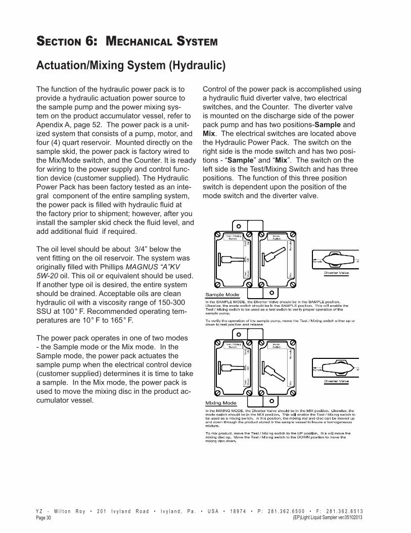
Actuation/Mixing System (Hydraulic)
The function of the hydraulic power pack is to provide a hydraulic actuation power source to the sample pump and the power mixing sys-tem on the product accumulator vessel, refer to Apendix A, page 52. The power pack is a unit-ized system that consists of a pump, motor, and four (4) quart reservoir. Mounted directly on the sample skid, the power pack is factory wired to the Mix/Mode switch, and the Counter. It is ready for wiring to the power supply and control func-tion device (customer supplied). The Hydraulic Power Pack has been factory tested as an inte-gral component of the entire sampling system, the power pack is filled with hydraulic fluid at the factory prior to shipment; however, after you install the sampler skid check the fluid level, and add additional fluid if required.
The oil level should be about 3/4” below the vent fitting on the oil reservoir. The system was originally filled with Phillips MAGNUS “A”KV 5W-20 oil. This oil or equivalent should be used. If another type oil is desired, the entire system should be drained. Acceptable oils are clean hydraulic oil with a viscosity range of 150-300 SSU at 100° F. Recommended operating tem-peratures are 10° F to 165° F.
The power pack operates in one of two modes - the Sample mode or the Mix mode. In the Sample mode, the power pack actuates the sample pump when the electrical control device (customer supplied) determines it is time to take a sample. In the Mix mode, the power pack is used to move the mixing disc in the product ac-cumulator vessel.
Control of the power pack is accomplished using a hydraulic fluid diverter valve, two electrical switches, and the Counter. The diverter valve is mounted on the discharge side of the power pack pump and has two positions-Sample and Mix. The electrical switches are located above the Hydraulic Power Pack. The switch on the right side is the mode switch and has two posi-tions - “Sample” and “Mix”. The switch on the left side is the Test/Mixing Switch and has three positions. The function of this three position switch is dependent upon the position of the mode switch and the diverter valve.

Section 7: SyStem operation
Page 31Y Z - M i l t o n R o y • 2 0 1 I v y l a n d R o a d • I v y l a n d , P a . • U S A • 1 8 9 7 4 • P : 2 8 1 . 3 6 2 . 6 5 0 0 • F : 2 8 1 . 3 6 2 . 6 5 1 3
(EP)Light Liquid Sampler ver.05102013
Preparing The System for Operation
Sample Pump PrimingBefore the pump begins normal operation after initial installation or maintenance, the sample pump must be purged of all air in the sample chamber. The purge valve on the Sample Pump/Balance Valve, refer to Apendix A, page 49-46, is used to evacuate the air from the chamber and to make sure the pump is liquid-packed. If the pump is not purged before being placed into operation, it will not function properly.
To purge the pump, open the purge valve locat-ed on the side of the Sample Pump/Discharge Valve assembly. The product supply valve can then be opened to allow pipeline product to purge the air within the pump. Once product begins exiting the purge valve, close the purge valve. The sample pump is now ready to begin operation.
Product Line TestClose the isolation valve located on the bottom of the Five-way Cross Assembly, refer to Apen-dix A, page 47. Stroke the sample pump until the system pressure reaches 1800 psi on the Five-Way Cross Assembly Gauge. The pres-sure should hold steady between pump strokes. Once the system is at 1800 psi, leak test all connections. Once the system has been tested, open the isolation valve located on the bottom of the Five-Way Cross Assembly.
Sample Vessel ConnectionConnect a constant pressure portable sample vessel (DuraSite) to the rob valve located on the Five-way Cross Assembly, refer to Apendix A, page 47 using a short section of 1/8” or 1/4” stainless steel tubing. The portable sample vessel must also be precharged to 100-150 psi above the vapor pressure of the product, refer to page 32. Open the rob valve allow product into the DuraSite as the pump takes samples. Close the rob valve and remove the sample vessel from the rob valve, at the end of each sample cycle, and replace it with a clean empty vessel for the next cycle.

Section 7: SyStem operation
Y Z - M i l t o n R o y • 2 0 1 I v y l a n d R o a d • I v y l a n d , P a . • U S A • 1 8 9 7 4 • P : 2 8 1 . 3 6 2 . 6 5 0 0 • F : 2 8 1 . 3 6 2 . 6 5 1 3Page 32 (EP)Light Liquid Sampler ver.05102013
DuraSite Sample Vessel ConnectionPurpose: The DuraSite Portable Sample Vessel permits the user to remove a liquid or gas hydrocarbon sample from a pipeline or a sampling device. This is accom-plished without changing the pressure of the product or exposing it to a contaminant fluid. If properly used and maintained the DuraSite will provide many years of safe, accurate and clean sampling.
Use: The DuraSite is a very safe device to use. As with any equipment dealing with flammable products, it is man-datory that a good, thorough operator training procedure be established prior to use.
Typical use of the cylinder would be as follows:
Step 1: (In The Lab) Connect a regulated inert gas sup-ply to the pre-charge valve. The product valve should be open. By carefully controlling the pre-charge valve and the regulator, the cylinder can be slowly charged with pre-charge gas (NOTE: This should be done slowly to prevent slamming the piston down to the opposite end). The pressure on the pre-charge pressure gauge should be brought to a reading of 10-50 psi above the expected pressure of the product in the field . Close the pre-charge valve and disconnect the gas supply. Check the pre-charge valve, relief device, and the pre-charge pressure gauge for leaks. Any leaks should be stopped before continuing. The vessel should be placed in a padded carrying case and made ready for field use.
STEP 2: FOR COLLECTION OF SAMPLE FROM COMPOSITE ACCUMULATOR VESSEL.
2a: Connect the product end of the pre-charged sample vessel to the product supply. (Sampler product removal valve) NOTE: the pre-charge pressure gauge reading should be greater than the product supply pressure reading. If not, repeat Step 1 above.
2b: Once the vessel is connected to the product supply, it is necessary to vent a small amount of product prior to filling the vessel. This assures fresh product and removes any air or gas when dealing with liquids. This can be done by loosening the product purge valve a very small amount until the product is purged. After thorough purging, the product purge valve should be tightened.
2c: The product pressure gauge reading should be 10-50 psi below the pre-charge pressure gauge reading. By carefully opening the pre-charge valve, the pressure
becomes equalized, then begins to drop below the prod-uct pressure. The pre-charge valve should be carefully controlled so as to not vent the pre-charge gas too fast.
2d: When the cylinder becomes a maximum of 80% full (see volume indicator), all valves should be closed. The product connection is slowly broken in order to vent any trapped product. After vessel removal, all connections should be checked for leaks and the pre-charge and prod-uct valve ports capped to prevent leakage.
2e: Pack the DuraSite in appropriate carrying case to meet D.O.T. guideline, with D.O.T. paperwork and transport to lab for analysis. Step 3: (In The Lab) Prior to analysis, the product should be mixed. This is accomplished simply and efficiently by inverting the cylinder end-over-end, causing the mixing ball to fall through the product. Approximately 10-12 trips of the mixing ball through the product assures a homogenous solution.
Step 4: The regulated pre-charge gas should be recon-nected to the pre-charge side of the cylinder. The pre-charge gas supply should remain open during analysis.
Step 5: Purging a small amount of product from the ves-sel removes unmixed product from the tee, relief device, gauge, etc. The unit can now be connected to a chromato-graph and the product analyzed.
Step 6: After analyzing, the remainder of the product should be dumped and the vessel properly cleaned. Nor-mal cleaning can be accomplished by rinsing the product end with a petroleum solvent and flushing with acetone. If a more thorough cleaning is required, the vessel should be disassembled.
WARNING: A portable sample vessel should never be filled to more than 80%. This allows a 20% pre-charge cushion to absorb thermal expansion of the product.
Shipping: Extreme care should be taken when preparing a vessel for shipment. Both valves should be capped to prevent possible leakage. The vessel should be placed in a snug-fitting, well-padded and durable case. All applicable DOT regulations should be adhered to.

Section 7: SyStem operation
Page 33Y Z - M i l t o n R o y • 2 0 1 I v y l a n d R o a d • I v y l a n d , P a . • U S A • 1 8 9 7 4 • P : 2 8 1 . 3 6 2 . 6 5 0 0 • F : 2 8 1 . 3 6 2 . 6 5 1 3
(EP)Light Liquid Sampler ver.05102013
figure 21

Section 7: SyStem operation
Y Z - M i l t o n R o y • 2 0 1 I v y l a n d R o a d • I v y l a n d , P a . • U S A • 1 8 9 7 4 • P : 2 8 1 . 3 6 2 . 6 5 0 0 • F : 2 8 1 . 3 6 2 . 6 5 1 3Page 34 (EP)Light Liquid Sampler ver.05102013
Notes

Section 8: SyStem maintenance
Page 35Y Z - M i l t o n R o y • 2 0 1 I v y l a n d R o a d • I v y l a n d , P a . • U S A • 1 8 9 7 4 • P : 2 8 1 . 3 6 2 . 6 5 0 0 • F : 2 8 1 . 3 6 2 . 6 5 1 3
(EP)Light Liquid Sampler ver.05102013
Preventative Maintenance ScheduleA preventative maintenance program serves to an-ticipate maintenance issues prior to waiting until the system requires service. Like changing the oil & filters in an automobile, by choosing to service the various parts and operation in the Sampling System at regular intervals, the technician can perform the maintenance service when desired, rather than when required, such as in the middle of night.
The key is to perform maintenance before it is re-quired. The preventative maintenance schedule implemented should consider the application of the sampler. Many of these considerations include: the weather environment; the condition of, the actuation gas, the product condition and quality, and the pump stroke frequency. All of these issues must be consid-ered when establishing a preventative maintenance schedule.
Recommended Maintenance ScheduleMonthly Inspection
1. Verify system pressures2. Check for leaks
Annual Inspection1. Rebuild pump2. Clean and service the pneumatic mixing valve if
so equipped4. Test the relief valve and service, as needed5. Test regulators and service, as needed6. Test the Light Liquid Sampler System perfor-
mance
Bi-Annual Inspection1. Perform the annual inspection listed above2. Replace solenoid if so equipped3. Rebuild Accumulator Vessel
Recommended Spare Parts ListPart # Description Recom-mended QuantityD3-0152 PNR-2P/LPR-2P pump seal replacement kit 1
OR
D3-0153 PNR-2H/LPR-2H pump seal replacement kit 1

Section 8: SyStem maintenance
Y Z - M i l t o n R o y • 2 0 1 I v y l a n d R o a d • I v y l a n d , P a . • U S A • 1 8 9 7 4 • P : 2 8 1 . 3 6 2 . 6 5 0 0 • F : 2 8 1 . 3 6 2 . 6 5 1 3Page 36 (EP)Light Liquid Sampler ver.05102013
Notes

Section 9: SyStem troubleShooting
Page 37Y Z - M i l t o n R o y • 2 0 1 I v y l a n d R o a d • I v y l a n d , P a . • U S A • 1 8 9 7 4 • P : 2 8 1 . 3 6 2 . 6 5 0 0 • F : 2 8 1 . 3 6 2 . 6 5 1 3
Light Liquid Sampler ver.05102013
How to Use This SectionThe recommendations contained in this section should be used as a preliminary information resource to remedy operational issues with the PNR-2P Sampling System. It is important to read all of the definitions and notes prior to initiating work.
Each subsection contains a description of the indi-cators followed by a step-by-step trouble shooting procedure.
For Additional HelpAny issue that can not be resolved through the use of this reference, please contact YZ Technical Service at:
T: 1.800.653.9435 T: 1.281.362.6500, International Calls F: 1.281.362.6513 Em: [email protected]
SAFETY NOTES• Always use extreme care when performing mainte-
nance on Sampling Systems. Always take neces-sary measures to assure that electrical classification in the area is considered, before, and during all repairs, and that necessary steps are taken to main-tain proper electrical procedures for the classifica-tion of the area.
• Take special care when disconnecting any fitting, to assure that product and/or pressure will not be re-leased when the connection is broken. This system may contain liquid and/or gas at high pressures.
Step-by-Step Resolution
Using a step-by-step method to resolve issues on the Sampling System will reduce maintenance time and assist in returning the system to service quicker.
The following represent the recommended chronology to resolve issues:
Resolve issues to the following order: a. Actuation Gas Pressure, page 37 b. Electrical Power, page 38 c. Sample Pulse, page 39 d. Pump Performance, page 39 e. Pre-Charge Pressure /Product Accumulator
Vessel , page 40
Actuation Gas PressureThis section should be used to troubleshoot sampler performance, when the Sample Pump will not actuate, and/or when the pneumatic power mixing system on the Accumulator Vessel will not function.
Actuation Gas Troubleshooting Steps1. Verify the supply gas valves, and regulators sup-
plying gas to the sampler system are properly functioning, and adjusted.
2. Disconnect the Pneumatic Supply connection at the top of the Sample Pump.
a. There should NOT be any gas pressure pres-ent. Gas pressure should be present for ONLY 3 seconds each time a sample pulse is received by the sample systems from the flow monitoring device, that signals the sampler when to take a sample.
b. Initiate a sample with the flow monitoring de-vice pulse, and observe to see if a 3 second burst of gas is expelled from the connection loosened in step 2 above.
- PNEUMATIC SYSTEMS
Section 9: SyStem troubleShooting
Y Z - M i l t o n R o y • 2 0 1 I v y l a n d R o a d • I v y l a n d , P a . • U S A • 1 8 9 7 4 • P : 2 8 1 . 3 6 2 . 6 5 0 0 • F : 2 8 1 . 3 6 2 . 6 5 1 3Page 38 (EP)Light Liquid Sampler ver.05102013
c. If a 3 second burst of gas is expelled from the connection loosened in step 2, the actuation system to the pump is functioning properly. Reconnect the Pneumatic Supply connec-tion to the top of the Sample Pump. Proceed to pump performance troubleshooting, if the problem seems to be with your pump, or proceed to step 3, if you are having difficulties with the power mixing of your sample system.
3. Disconnect the tubing at the top of the Actuator Head of the Product Accumulator vessel. There should not be any pressure there until the Mixing Valve is placed in the down mixing position.
a. If gas is flowing continually when this line is disconnected, the Mixing Valve should be repaired, or replaced.
b. If gas does not flow to the loosened connec- tion when the Mixing Valve is actuated to the down position, try moving the valve to the up position, and see if you get gas flow at the loosened connection. If you still have no gas flow to the loosened connection, the Mixing Valve should be repaired, or replaced.
c. If gas does flow properly, to the loosened connection, when the Mixing Valve is placed in the down mixing position, check the vent/ muffler on the Mixing Valve to see if it may be stopped up. Clean or replace the vent/muffler as required.
Electrical PowerIMPORTANT NOTE: All electronics are housed in explosion proof enclosures and are rated for use in Class I, Divi-sion 1, Groups C and D hazardous locations.
The power supply to the sampler must be properly connected and supplying power to the sample sys-tem, before it can be expected to perform. Often elec-trical storms, or other electrical surges that occur at the sampler site may cause interruption of the power supply to the sampler. The power is used to drive the solenoid for a duration of 3 seconds each time a sample is called for by the flow monitoring device connected to the sampler system. Electrical power troubleshooting will include steps to assure the power is actually getting to the solenoid for the required du-ration, and that the solenoid is activating the sample pump. The typical symptom to lead a technician to this step would be that the sample pump is not being actu-ated when a pulse from the flow monitoring device sends a dry contact sample pulse to the sampler.
Electrical Power Troubleshooting Steps
CAUTION: Prior to opening the electrical enclosure be sure to disconnect all power and pulse connections at the safe end of wiring or perform test to assure the area of the enclosure is safe to open the enclosure.
1. Verify the power is actually reaching the solenoid in the Sample System electrical enclosure. Test for power at the solenoid by connecting your Volt-meter to the solenoid terminal pins, refer System Control and Electronics in Section 4.
- PNEUMATIC SYSTEMS

Section 9: SyStem troubleShooting
Page 39Y Z - M i l t o n R o y • 2 0 1 I v y l a n d R o a d • I v y l a n d , P a . • U S A • 1 8 9 7 4 • P : 2 8 1 . 3 6 2 . 6 5 0 0 • F : 2 8 1 . 3 6 2 . 6 5 1 3
Light Liquid Sampler ver.05102013
Sample PulseIMPORTANT NOTE: All electronics are housed in explosion proof enclosures and are rated for use in Class I, Divi-sion 1, Groups C and D hazardous locations.
The Sample Pulse to the sampler must be properly connected and supplying power to the pneumatic solenoid, before the sampler system can be expected to perform. Often electrical storms, or other electrical surges that occur at the sampler site may cause inter-ruption of the Sample Pulse to the sampler. The pulse power is used to drive the solenoid for a duration of 3 seconds each time a sample is called for by the flow monitoring device connected to the sampler system. Sample Pulse troubleshooting will include steps to as-sure the power is actually getting to the solenoid for the required duration, and that the solenoid is activat-ing the sample pump. The typical symptom to lead a technician to this step would be that the sample pump is not being actuated when a pulse from the flow monitoring device sends a Sample Pulse signal to the sampler. The origin of this Sample Pulse is in the flow monitoring equipment, that is not actually a part of the sampler system; therefore troubleshoot-ing will be limited to verifying that the sampler system does respond properly when an appropriate pulse is generated.
Sample Pulse Troubleshooting Steps
CAUTION: Prior to opening the electrical enclosure be sure to disconnect all power and pulse connections at the safe end of wiring or perform test to assure the area of the enclosure is safe to open the enclosure. These connections carry power supply voltage.
1. Verify the power is actually reaching the Solenoid on the Sample Skid.
a. Test for power at the solenoid connection by connecting your Voltmeter to the solenoid wires.
b. If there is not power at the solenoid for 3
seconds when a sample signal is being sent to the sampler system by the flow monitoring device, check the breaker, and wiring back to the flow monitoring device. Repair any loose or broken wires, reset or replace circuit breaker as required.
2. If step 1 above does not resolve your problem, proceed to troubleshooting the output from your flow monitoring device.
Pump PerformanceThere are many factors that affect pump perfor-mance. Some are within the pump, while others are outside factors that affect pump performance.
Pump Performance Troubleshooting Steps1. Actual performance of the Actuation Gas, and
Electrical Power issues should have already been dealt with, If not , perform those troubleshooting steps before proceeding to step 2.
2. Close the isolation valve located on the bottom of the Five-way Cross Assembly. Stroke the sample pump while observing the pressure reading on the Five-way Cross Assembly Gauge. The sys-tem pressure should steadily build to 1800 psi . The pressure should hold steady between pump strokes. Once the system is at 1800 psi, leak test all connections. Once the system has been tested, open the isolation valve located on the bottom of the Five-way Cross Assembly. Comple-tion of this test verifies the pump performance is O.K.
- PNEUMATIC SYSTEMS

Section 9: SyStem troubleShooting
Y Z - M i l t o n R o y • 2 0 1 I v y l a n d R o a d • I v y l a n d , P a . • U S A • 1 8 9 7 4 • P : 2 8 1 . 3 6 2 . 6 5 0 0 • F : 2 8 1 . 3 6 2 . 6 5 1 3Page 40 (EP)Light Liquid Sampler ver.05102013
3. The next step, if the pump did not pass the test in step 2, is to verify that the pump is fully liquid packed with liquid product to be pumped. The Sample Pump must be purged of all air in the sample chamber, before it can pump liquid prod-uct. The purge valve on the sample pump is used to evacuate the air from the chamber and to make sure the pump is liquid-packed. If the pump is not purged properly, it will not function properly.
a. Open the purge valve located on the left side of the sample pump.
b. Next open the product supply valve to allow pipeline product to purge the air within the pump.
c. Once product begins exiting the purge valve, close the purge valve. The sample pump is now ready to begin operation. Perform pump test #2 again. If your product is not consis tently in a single phase liquid state the pump will vapor lock again, and repriming will be necessary, repeatedly, till the phase condition of the product is resolved.
4. If during the pump troubleshooting step 2, you observed the pressure on the Five-way Cross Assembly Gauge jumping from pipeline pressure to a higher pressure, during the pump stroke, but immediately returning to pipeline pressure after the stroke, the Discharge Valve Assembly should be replaced.
5. If during the pump troubleshooting step 2, you observed the pressure on the Five-way Cross Assembly Gauge build steadily to pipeline pres-sure, then stop building at pipeline pressure, the Sample Pump inlet check is not holding. Typi-cally installing a YZ Repair Kit P/N D3-0152, will resolve this situation.
Pre-Charge/Product AccumulatorThe Product Accumulator works in conjunction with the Pre-Charge Vessel to maintain the integrity of captured sample in the sampler system. The Prod-uct Accumulator Vessel may be repaired on site, but requires some special tools to do so, and it is recom-mended that if this vessel needs service, you should contact YZ - Milton Roy Technical Service @ 1.281-362-6500 to obtain a Return Authorization Number to return the Product Accumulator Vessel to YZ for reconditioning. The pre-charge vessel pressure must remain at a pressure that exceeds the critical vapor pressure of the product being sampled. A typical pressure setting should be 100 PSI over the pipeline pressure.
Pre-Charge/Product Accumulator Troubleshooting Steps1. If the charge in the vessel is low, recharge it to the
proper pressure, by connecting an external source of inert gas to the Pre-Charge Isolation Valve, and open the valve until the Pre-Charge Vessel pressure is once again at the desired pressure.
2. Close the Pre-Charge Isolation Valve.
3. Disconnect the external source of inert gas.
4. Wrap a 1/4” MNPT plug with TFE tape, and install it in the Pre-Charge Isolation Valve.
5. Use liquid soap to leak test all connections on the Pre-Charge Vessel, Pre-Charge Isolation Valve, Tubing to the Accumulator Vessel, and Pre-Charge connection to the Accumulator Vessel. Fix any leak detected.
6. If no leaks were found in step 5, look at the most recent analysis report on product taken from this sampler, to see if an abnormal amount of inert gas of the type used for Pre-Charge was present in the sample. If Pre-Charge gas is found in the sample, contact YZ - Milton Roy Techni-cal Service @ 1.281-362-6500 to obtain a Return Authorization Number to return the Sample Ac-cumulator Vessel to YZ for reconditioning.
- PNEUMATIC SYSTEMS

Section 9: SyStem troubleShooting
Page 41Y Z - M i l t o n R o y • 2 0 1 I v y l a n d R o a d • I v y l a n d , P a . • U S A • 1 8 9 7 4 • P : 2 8 1 . 3 6 2 . 6 5 0 0 • F : 2 8 1 . 3 6 2 . 6 5 1 3
Light Liquid Sampler ver.05102013
How to Use This SectionThe recommendations contained in this section should be used as a preliminary information resource to remedy operational issues with the LPR-2H Sampling System. It is important to read all of the definitions and notes prior to initiating work.
Each subsection contains a description of the indi-cators followed by a step-by-step trouble shooting procedure.
For Additional HelpAny issue that can not be resolved through the use of this reference, please contact YZ Technical Service at:
T: 1.800.653.9435 T: 1.281.362.6500, International Calls F: 1.281.362.6513 Em: [email protected]
SAFETY NOTES• Always use extreme care when performing mainte-
nance on Sampling Systems. Always take neces-sary measures to assure that electrical classification in the area is considered, before, and during all repairs, and that necessary steps are taken to main-tain proper electrical procedures for the classifica-tion of the area.
• Take special care when disconnecting any fitting, to assure that product and/or pressure will not be re-leased when the connection is broken. This system may contain liquid and/or gas at high pressures.
Step-by-Step Resolution
Using a step-by-step method to resolve issues on the Sampling System will reduce maintenance time and assist in returning the system to service quicker.
The following represent the recommended chronology to resolve issues:
Resolve issues to the following order: a. Electrical Power, page 41 b. Hydraulic Power, page 43
Electrical PowerCAUTION: Prior to opening the electrical enclosure be sure to disconnect all power and pulse connections at the safe end of wiring or perform test to assure the area of the enclosure is safe to open the enclosure.
The 120 VAC power supply to the sampler must be properly connected and supplying power (120 VAC @ 20 amps) to the sample system, before it can be expected to perform. Often electrical storms, or other electrical surges that occur at the sampler site may cause interruption of the power supply to the sam-pler. The power is used to drive the Hydraulic Power Pack for a minimum duration of 5 seconds each time a sample is called for by the pulse as provided by a flow monitoring device connected to the sampler system, and to run the power pack longer during the sample mixing mode of operation. Electrical power troubleshooting will include steps to assure the 120 VAC power is actually getting to the Power Pack for the required duration. The typical symptom to lead a technician to this step would be that the sample pump is not being actuated when a pulse from the flow mon-itoring device sends a sample pulse to the sampler.
- HYDRAULIC SYSTEMS

Section 9: SyStem troubleShooting
Y Z - M i l t o n R o y • 2 0 1 I v y l a n d R o a d • I v y l a n d , P a . • U S A • 1 8 9 7 4 • P : 2 8 1 . 3 6 2 . 6 5 0 0 • F : 2 8 1 . 3 6 2 . 6 5 1 3Page 42 (EP)Light Liquid Sampler ver.05102013
Electrical Power Troubleshooting Steps
CAUTION: Prior to opening the electrical enclosure be sure to disconnect all power and pulse connections at the safe end of wiring or perform test to assure the area of the enclosure is safe to open the enclosure.
1. Verify the 120VAC power is actually reaching the Hydraulic Power Pack, and Control System. (The power to the Hydraulic Power Pack is directly con-nected to the Control System power connection; therefore if power is getting to the Control System, it should be getting to the Hydraulic Power Pack).
a. Test for continuous 120 VAC to the Hydraulic Power Pack/counter, by connecting your AC Voltmeter to the Neutral and Hot 120 VAC wiring connections to the Test Switch, refer to Appendix A Electrical Wiring, Hydraulic Power Pack/Test Switch, Page 55.
b. If there is not 120VAC continuous power to the Test Switch, check the breaker, and AC wiring back to the AC source. Repair any loose or broken wires, reset or replace circuit breaker as required.
Sample Pulse1. The next Electrical Power test is to see if the
Control System functions properly when a 24 VDC pulse is applied.
Once continuous 120 VAC power is verified at the Control System, (step #1 above); Connect your AC Voltmeter to the RELAY Input Pulsed 24 VDC wiring connection, and the 24 VDC Neutral wiring connection, refer to Appendix A Electrical Wiring, Hydraulic Power Pack/Test Switch, Page 55. This should be a pulsed 24 VDC with a MINIMUM duration of 5 Sec. ONLY when the Control System is activated, by your flow monitoring equipment.
2. The final step in troubleshooting the electrical power for the sampler, would be to replace the relay or Hydraulic Power Pack itself. They are available from YZ - Milton Roy.
- HYDRAULIC SYSTEMS

Section 9: SyStem troubleShooting
Page 43Y Z - M i l t o n R o y • 2 0 1 I v y l a n d R o a d • I v y l a n d , P a . • U S A • 1 8 9 7 4 • P : 2 8 1 . 3 6 2 . 6 5 0 0 • F : 2 8 1 . 3 6 2 . 6 5 1 3
Light Liquid Sampler ver.05102013
- HYDRAULIC SYSTEMS
Hydraulic Power
Hydraulic power is measured in terms of hydraulic pressure. There are several factors that may cause your systems to not provide sufficient hydraulic pres-sure, as outlined below.CAUTION: The Hydraulic Power Pack should NEVER be oper-ated without recommended oil in the reservoir. Do not operate the Power Pack at temperatures over 140 F., or less than 0 F.
Hydraulic Power Troubleshooting Steps
1. Verify the Hydraulic Power Pack is properly filled with the oil.
a. Remove the oil reservoir Filler/Breather Cap.
b. Check the oil level. It should be approximately 1” below the lip of the oil reservoir.
c. If additional oil is required add oil of a similar type as has been previously installed in the
Hydraulic Power Pack.IMPORTANT NOTE: Oil type should be 10 WT. Phillips Magna-A hydraulic oil, automatic transmission fluid, or any clean hydraulic oil with a viscosity range of 150-300 SSU @ 100 F.
2. If the hydraulic system begins making an unusual screeching noise, and the oil level is correct, check and clean, or replace the reservoir filter.
a. Drain the oil from the oil reservoir, utilizing the oil drain plug at the lower end on the oil reser- voir, opposite the power pack electrical motor.
b. Remove the (4) hex head cap screws that hold the oil reservoir to the Power Pack coupler housing, and slide the reservoir off.
b. Examine, clean, and/or replace the filter on the end of the oil pump suction pipe.
3. Verify hydraulic power system pressure. This may be done in two ways, as detailed below.
a. Pressure Test Method #1: • Disconnect the pressure out line from the Hydraulic Power Pack, refer to illustration, page 55. • Install a pressure gage into the pressure out port from the Power Pack. CAUTION: The use a high quality gage capable of with standing at least 1,000 psi of pressure.
• Test run the Power Pack, and observe the dead headed pressure on the gage. Pressure should be between 350 psi - 400 psi. • If the pressure is not sufficient contact YZ - Milton Roy • Remove the gage, and reconnect the original tubing to the Sample Pump. • This is a bidirectional Power Pack, so now repeat the process with the pump running the other direction, and with the gage in the other port from the Power Pack.
b. Pressure Test Method #2: • Disconnect the pressure in line to the Sample Pump, from the Hydraulic Power Pack, refer to illustration, page 55. • Install an inline Tee, with a pressure gage into the pressure in port of the Sample Pump, and re-connect the tubing from the Power Pack. CAUTION: Use a high quality gage capable of with standing at least 1,000 psi of pressure.

Section 9: SyStem troubleShooting
Y Z - M i l t o n R o y • 2 0 1 I v y l a n d R o a d • I v y l a n d , P a . • U S A • 1 8 9 7 4 • P : 2 8 1 . 3 6 2 . 6 5 0 0 • F : 2 8 1 . 3 6 2 . 6 5 1 3Page 44 (EP)Light Liquid Sampler ver.05102013
- HYDRAULIC SYSTEMS
Notes
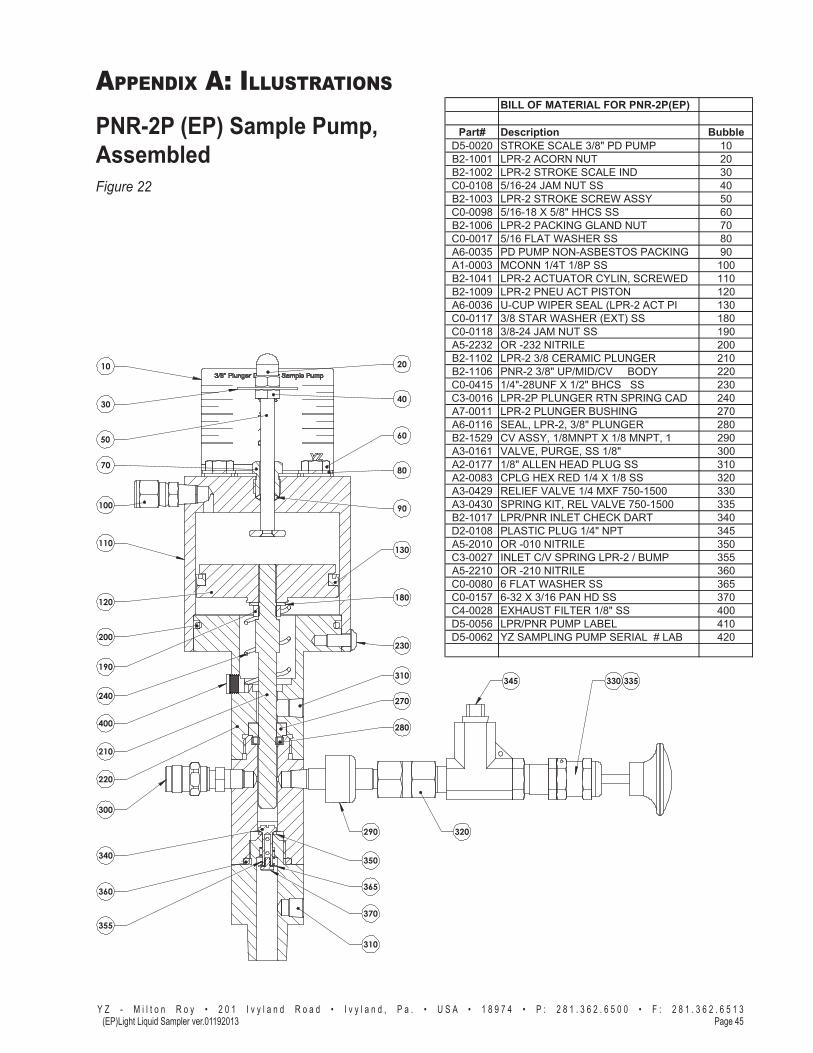
APPENDIX A: ILLUSTRATIONS
Page 45Y Z - M i l t o n R o y • 2 0 1 I v y l a n d R o a d • I v y l a n d , P a . • U S A • 1 8 9 7 4 • P : 2 8 1 . 3 6 2 . 6 5 0 0 • F : 2 8 1 . 3 6 2 . 6 5 1 3
(EP)Light Liquid Sampler ver.01192013
PNR-2P (EP) Sample Pump, Assembled Figure 22
50
10
270
20
30 40
90
60
80
130
180
100
110
120
365
190
200
70
240
210
290
220
300
310
310
345
320
350
355
230
340
370
360
400 280
330 335
BILL OF MATERIAL FOR PNR-2P(EP)
Part# Description BubbleD5-0020 STROKE SCALE 3/8" PD PUMP 10B2-1001 LPR-2 ACORN NUT 20B2-1002 LPR-2 STROKE SCALE IND 30C0-0108 5/16-24 JAM NUT SS 40B2-1003 LPR-2 STROKE SCREW ASSY 50C0-0098 5/16-18 X 5/8" HHCS SS 60B2-1006 LPR-2 PACKING GLAND NUT 70C0-0017 5/16 FLAT WASHER SS 80A6-0035 PD PUMP NON-ASBESTOS PACKING 90A1-0003 MCONN 1/4T 1/8P SS 100B2-1041 LPR-2 ACTUATOR CYLIN, SCREWED 110B2-1009 LPR-2 PNEU ACT PISTON 120A6-0036 U-CUP WIPER SEAL (LPR-2 ACT PI 130C0-0117 3/8 STAR WASHER (EXT) SS 180C0-0118 3/8-24 JAM NUT SS 190A5-2232 OR -232 NITRILE 200B2-1102 LPR-2 3/8 CERAMIC PLUNGER 210B2-1106 PNR-2 3/8" UP/MID/CV BODY 220C0-0415 1/4"-28UNF X 1/2" BHCS SS 230C3-0016 LPR-2P PLUNGER RTN SPRING CAD 240A7-0011 LPR-2 PLUNGER BUSHING 270A6-0116 SEAL, LPR-2, 3/8" PLUNGER 280B2-1529 CV ASSY, 1/8MNPT X 1/8 MNPT, 1 290A3-0161 VALVE, PURGE, SS 1/8" 300A2-0177 1/8" ALLEN HEAD PLUG SS 310A2-0083 CPLG HEX RED 1/4 X 1/8 SS 320A3-0429 RELIEF VALVE 1/4 MXF 750-1500 330A3-0430 SPRING KIT, REL VALVE 750-1500 335B2-1017 LPR/PNR INLET CHECK DART 340D2-0108 PLASTIC PLUG 1/4" NPT 345A5-2010 OR -010 NITRILE 350C3-0027 INLET C/V SPRING LPR-2 / BUMP 355A5-2210 OR -210 NITRILE 360C0-0080 6 FLAT WASHER SS 365C0-0157 6-32 X 3/16 PAN HD SS 370C4-0028 EXHAUST FILTER 1/8" SS 400D5-0056 LPR/PNR PUMP LABEL 410D5-0062 YZ SAMPLING PUMP SERIAL # LAB 420

APPENDIX A: ILLUSTRATIONS
Y Z - M i l t o n R o y • 2 0 1 I v y l a n d R o a d • I v y l a n d , P a . • U S A • 1 8 9 7 4 • P : 2 8 1 . 3 6 2 . 6 5 0 0 • F : 2 8 1 . 3 6 2 . 6 5 1 3Page 46 (EP)Light Liquid Sampler ver.01192013
160
10 20
5060
70 80
90
140
170190
130
180
150
200
220
220
230
250
270
290
300
310
320340
345
350
355
365
400
370
360
30
100
40
100
120
240
220
110
260
280
210330 335
PNR-2H (EP) Sample Pump, Assembled Figure 23
BILL OF MATERIAL FOR PNR-2H(EP)
Part# Description BubbleD5-0020 STROKE SCALE 3/8" PD PUMP 10B2-1001 LPR-2 ACORN NUT 20B2-1002 LPR-2 STROKE SCALE IND 30C0-0108 5/16-24 JAM NUT SS 40B2-1003 LPR-2 STROKE SCREW ASSY 50C0-0098 5/16-18 X 5/8" HHCS SS 60B2-1006 LPR-2 PACKING GLAND NUT 70C0-0017 5/16 FLAT WASHER SS 80A6-0035 PD PUMP NON-ASBESTOS PACKING 90A1-0003 MCONN 1/4T 1/8P SS 100B2-1041 LPR-2 ACTUATOR CYLIN, SCREWED 110B2-1008 LPR-2 HYD ACTUATOR PISTON 120A6-0036 U-CUP WIPER SEAL (LPR-2 ACT PI 130B2-1010 LPR-2 BUMP VALVE DART 140C3-0027 INLET C/V SPRING LPR-2 / BUMP 150C0-0080 6 FLAT WASHER SS 160C0-0056 6-32 X 1/2" SHCS SS 170C0-0117 3/8 STAR WASHER (EXT) SS 180C0-0118 3/8-24 JAM NUT SS 190A5-2232 OR -232 NITRILE 200B2-1102 LPR-2 3/8 CERAMIC PLUNGER 210B2-1106 PNR-2 3/8" UP/MID/CV BODY 220C0-0415 1/4"-28UNF X 1/2" BHCS SS 230C3-0026 LPR-2H PLUNGER RETURN SPRING 240B2-1103 LPR-2 3/8 RETURN SPRING SUPORT 250A6-0037 SEAL, 3/8" PLUNGER, MOLY 260A7-0011 LPR-2 PLUNGER BUSHING 270A6-0116 SEAL, LPR-2, 3/8" PLUNGER 280B2-1529 CV ASSY, 1/8MNPT X 1/8 MNPT, 1 290A3-0161 VALVE, PURGE, SS 1/8" 300A2-0177 1/8" ALLEN HEAD PLUG SS 310A2-0083 CPLG HEX RED 1/4 X 1/8 SS 320A3-0429 RELIEF VALVE 1/4 MXF 750-1500 330A3-0430 SPRING KIT, REL VALVE 750-1500 335B2-1017 LPR/PNR INLET CHECK DART 340D2-0108 PLASTIC PLUG 1/4" NPT 345A5-2010 OR -010 NITRILE 350C3-0027 INLET C/V SPRING LPR-2 / BUMP 355A5-2210 OR -210 NITRILE 360C0-0080 6 FLAT WASHER SS 365C0-0157 6-32 X 3/16 PAN HD SS 370C4-0028 EXHAUST FILTER 1/8" SS 400D5-0056 LPR/PNR PUMP LABEL 410D5-0062 YZ SAMPLING PUMP SERIAL # LAB 420

APPENDIX A: ILLUSTRATIONS
Page 47Y Z - M i l t o n R o y • 2 0 1 I v y l a n d R o a d • I v y l a n d , P a . • U S A • 1 8 9 7 4 • P : 2 8 1 . 3 6 2 . 6 5 0 0 • F : 2 8 1 . 3 6 2 . 6 5 1 3
(EP)Light Liquid Sampler ver.01192013
5-Way Cross Assembly, Figure 24

APPENDIX A: ILLUSTRATIONS
Y Z - M i l t o n R o y • 2 0 1 I v y l a n d R o a d • I v y l a n d , P a . • U S A • 1 8 9 7 4 • P : 2 8 1 . 3 6 2 . 6 5 0 0 • F : 2 8 1 . 3 6 2 . 6 5 1 3Page 48 (EP)Light Liquid Sampler ver.01192013
Pre-Charge Assembly, Figure 25

APPENDIX A: ILLUSTRATIONS
Page 49Y Z - M i l t o n R o y • 2 0 1 I v y l a n d R o a d • I v y l a n d , P a . • U S A • 1 8 9 7 4 • P : 2 8 1 . 3 6 2 . 6 5 0 0 • F : 2 8 1 . 3 6 2 . 6 5 1 3
(EP)Light Liquid Sampler ver.01192013
Pneumatic Mixed Accumulator Vessel, Figure 26

APPENDIX A: ILLUSTRATIONS
Y Z - M i l t o n R o y • 2 0 1 I v y l a n d R o a d • I v y l a n d , P a . • U S A • 1 8 9 7 4 • P : 2 8 1 . 3 6 2 . 6 5 0 0 • F : 2 8 1 . 3 6 2 . 6 5 1 3Page 50 (EP)Light Liquid Sampler ver.01192013
Pneumatic Mixing System-Accumulator, Figure 27

APPENDIX A: ILLUSTRATIONS
Page 51Y Z - M i l t o n R o y • 2 0 1 I v y l a n d R o a d • I v y l a n d , P a . • U S A • 1 8 9 7 4 • P : 2 8 1 . 3 6 2 . 6 5 0 0 • F : 2 8 1 . 3 6 2 . 6 5 1 3
(EP)Light Liquid Sampler ver.01192013
Mixing System Figure 28
Instrument Air(80PSI Recommended
100PSI Max)
Filter RegulatorExplosion ProofEnclosure
Mixing Valve
3-Way SloenoidValveProduct Accumulator
Vessel

APPENDIX A: ILLUSTRATIONS
Y Z - M i l t o n R o y • 2 0 1 I v y l a n d R o a d • I v y l a n d , P a . • U S A • 1 8 9 7 4 • P : 2 8 1 . 3 6 2 . 6 5 0 0 • F : 2 8 1 . 3 6 2 . 6 5 1 3Page 52 (EP)Light Liquid Sampler ver.01192013
Hydraulic Mixed Accumulator Vessel, Figure 29

APPENDIX A: ILLUSTRATIONS
Page 53Y Z - M i l t o n R o y • 2 0 1 I v y l a n d R o a d • I v y l a n d , P a . • U S A • 1 8 9 7 4 • P : 2 8 1 . 3 6 2 . 6 5 0 0 • F : 2 8 1 . 3 6 2 . 6 5 1 3
(EP)Light Liquid Sampler ver.01192013
Hydraulic Mixing System-Accumulator, Figure 30

APPENDIX A: ILLUSTRATIONS
Y Z - M i l t o n R o y • 2 0 1 I v y l a n d R o a d • I v y l a n d , P a . • U S A • 1 8 9 7 4 • P : 2 8 1 . 3 6 2 . 6 5 0 0 • F : 2 8 1 . 3 6 2 . 6 5 1 3Page 54 (EP)Light Liquid Sampler ver.01192013
Hydraulic Mixing System Figure 31

APPENDIX A: ILLUSTRATIONS
Page 55Y Z - M i l t o n R o y • 2 0 1 I v y l a n d R o a d • I v y l a n d , P a . • U S A • 1 8 9 7 4 • P : 2 8 1 . 3 6 2 . 6 5 0 0 • F : 2 8 1 . 3 6 2 . 6 5 1 3
(EP)Light Liquid Sampler ver.01192013
Hydraulic Power Pack Figure 32
Pressure Test #1
Pressure Test #1a

APPENDIX A: ILLUSTRATIONS
Y Z - M i l t o n R o y • 2 0 1 I v y l a n d R o a d • I v y l a n d , P a . • U S A • 1 8 9 7 4 • P : 2 8 1 . 3 6 2 . 6 5 0 0 • F : 2 8 1 . 3 6 2 . 6 5 1 3Page 56 (EP)Light Liquid Sampler ver.01192013
Electrical Wiring, Hydraulic Power Pack/Test Switch

APPENDIX A: ILLUSTRATIONS
Page 57Y Z - M i l t o n R o y • 2 0 1 I v y l a n d R o a d • I v y l a n d , P a . • U S A • 1 8 9 7 4 • P : 2 8 1 . 3 6 2 . 6 5 0 0 • F : 2 8 1 . 3 6 2 . 6 5 1 3
(EP)Light Liquid Sampler ver.01192013
Notes

Y Z - M i l t o n R o y • 2 0 1 I v y l a n d R o a d • I v y l a n d , P a . • U S A • 1 8 9 7 4 • P : 2 8 1 . 3 6 2 . 6 5 0 0 • F : 2 8 1 . 3 6 2 . 6 5 1 3Page 1 (EP)Light Liquid Sampler ver. 05102013
(EP)Light Liquid Sampler ELM Addendum

Y Z - M i l t o n R o y • 2 0 1 I v y l a n d R o a d • I v y l a n d , P a . • U S A • 1 8 9 7 4 • P : 2 8 1 . 3 6 2 . 6 5 0 0 • F : 2 8 1 . 3 6 2 . 6 5 1 3Page 1 (EP)Light Liquid Sampler ver. 05102013
Electronic Level MonitorPRODUCT DESCRIPTION
The Level Plus MC420 liquid level sensor is a multifunctional transmitter with a 4-20 mA loop and HART (Highway Addressable Remote Transducer) communications. It provides one analog output for level or interface. The output can be monitored using the 4-20 mA signal or a HART device (hand-held or MTS PC-compatible software).
the Level Plus MC420 transmitter housing is a NEMA 4X electropolished stainless steel and I.S. Ap-proval.
The outer pipe is constructed of 10 mm diameter rigid outer pipe (316L satinless steel).

Y Z - M i l t o n R o y • 2 0 1 I v y l a n d R o a d • I v y l a n d , P a . • U S A • 1 8 9 7 4 • P : 2 8 1 . 3 6 2 . 6 5 0 0 • F : 2 8 1 . 3 6 2 . 6 5 1 3Page 2 (EP)Light Liquid Sampler ver. 05102013
Electronic Level Monitor

Y Z - M i l t o n R o y • 2 0 1 I v y l a n d R o a d • I v y l a n d , P a . • U S A • 1 8 9 7 4 • P : 2 8 1 . 3 6 2 . 6 5 0 0 • F : 2 8 1 . 3 6 2 . 6 5 1 3Page 3 (EP)Light Liquid Sampler ver. 05102013
Electronic Level Monitor

Y Z - M i l t o n R o y • 2 0 1 I v y l a n d R o a d • I v y l a n d , P a . • U S A • 1 8 9 7 4 • P : 2 8 1 . 3 6 2 . 6 5 0 0 • F : 2 8 1 . 3 6 2 . 6 5 1 3Page 4 (EP)Light Liquid Sampler ver. 05102013
Electronic Level Monitor

Y Z - M i l t o n R o y • 2 0 1 I v y l a n d R o a d • I v y l a n d , P a . • U S A • 1 8 9 7 4 • P : 2 8 1 . 3 6 2 . 6 5 0 0 • F : 2 8 1 . 3 6 2 . 6 5 1 3Page 5 (EP)Light Liquid Sampler ver. 05102013
Electronic Level Monitor

Y Z - M i l t o n R o y • 2 0 1 I v y l a n d R o a d • I v y l a n d , P a . • U S A • 1 8 9 7 4 • P : 2 8 1 . 3 6 2 . 6 5 0 0 • F : 2 8 1 . 3 6 2 . 6 5 1 3Page 6 (EP)Light Liquid Sampler ver. 05102013
Electronic Level Monitor

Y Z - M i l t o n R o y • 2 0 1 I v y l a n d R o a d • I v y l a n d , P a . • U S A • 1 8 9 7 4 • P : 2 8 1 . 3 6 2 . 6 5 0 0 • F : 2 8 1 . 3 6 2 . 6 5 1 3Page 7 (EP)Light Liquid Sampler ver. 05102013
Electronic Level Monitor

Y Z - M i l t o n R o y • 2 0 1 I v y l a n d R o a d • I v y l a n d , P a . • U S A • 1 8 9 7 4 • P : 2 8 1 . 3 6 2 . 6 5 0 0 • F : 2 8 1 . 3 6 2 . 6 5 1 3Page 8 (EP)Light Liquid Sampler ver. 05102013
Electronic Level Monitor


201 Ivyland RoadIvyland, Pa. 18974
800.653.9435P: 281.362.6500F: 281.362.6513
Em: [email protected]: www.yzsystems.com
Lit# IO-LPR / PNR