epe 213 : measuring instruments - bu
TRANSCRIPT
EPE 213 : Measuring InstrumentsFall 2019
Lecture (6)
Dr. Mohamed Salah Selmy
Benha UniversityFaculty of Engineering at ShoubraElectrical Engineering Department
Dr. Mohamed Selmy
Electrical Power and Machines (EPM) 2nd Year Electrical Power, Fall 2019 Measuring Instruments, EPE 213

Outline:
• Recap!
• Introduction to signal generator.
• Function Generators.
• Mini-project progress.
Dr. Mohamed Salah 2
Course Content:
Dr. Mohamed Salah 3
Recap!
Introduction to logic circuits and digital systems.
Measurements characteristics.
Digital Voltmeters and Digital Multimeters.
Digital frequency meters.
Digital Storage Oscilloscope.
Signal generators (Function generator). Instrument Calibration.
Sensors and Transducers.

Recap!
Dr. Mohamed Salah 4
Analog oscilloscope
Digital oscilloscope
Advantages/ disadvantages of Digital oscilloscope
Digital oscilloscope applications
Introduction to signal generator:
Dr. Mohamed Salah 5
A signal generator is an electronic device (or equipment) that generates repeating or nonrepeating electronic signals (in either the analog or digital domains).
A signal generator used in designing, testing, troubleshooting in electronic devices and circuits. For example, audio frequency (AF) and radio-frequency (RF) signals are needed for the repair of radio, television and other electronic equipment.
Introduction to signal generator:
Dr. Mohamed Salah 6
The generation of signals is important in electronic system. The signal generator is used to provide known test condition for the performance evaluation of various electronic systems and for replacing missing signals in system.
For generating sinusoidal signals of known frequency we use oscillator (Sinewave generator). This device covers the frequency range from a few Hz to many GHz.
Many times we need non-sinusoidal waves such as rectangularwaves, sawtooth waves, square wave etc. For generating non-sinusoidal wave we use multivibrators. It is a switching circuit, capable of storing binary numbers, counting pulses, synchronizing arithmetic operations and performing other essential functions used in digital systems.
Function Generator:
Dr. Mohamed Salah 7
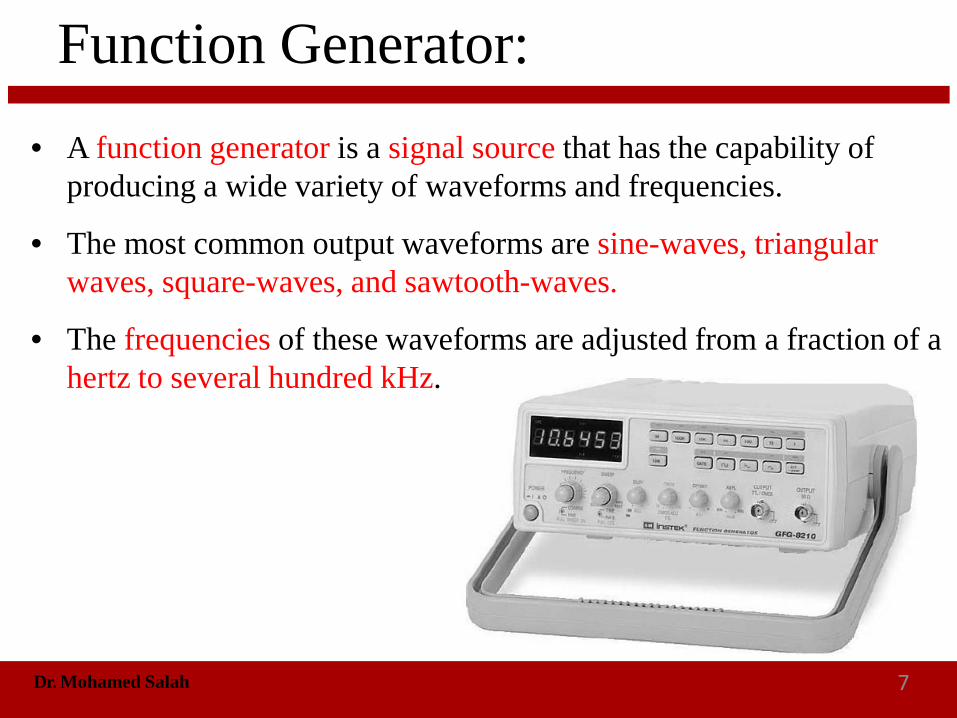
• A function generator is a signal source that has the capability of producing a wide variety of waveforms and frequencies.
• The most common output waveforms are sine-waves, triangular waves, square-waves, and sawtooth-waves.
• The frequencies of these waveforms are adjusted from a fraction of a hertz to several hundred kHz.
Function Generator:
Dr. Mohamed Salah 8
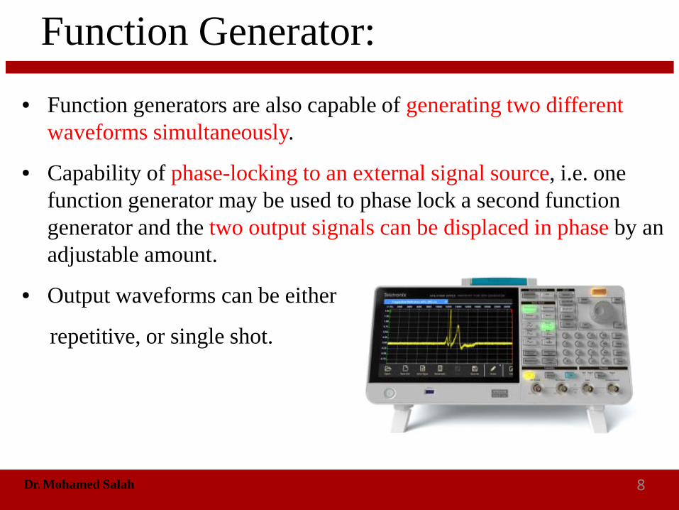
• Function generators are also capable of generating two different waveforms simultaneously.
• Capability of phase-locking to an external signal source, i.e. one function generator may be used to phase lock a second function generator and the two output signals can be displaced in phase by an adjustable amount.
• Output waveforms can be either
repetitive, or single shot.

Function Generator:
Dr. Mohamed Salah 9
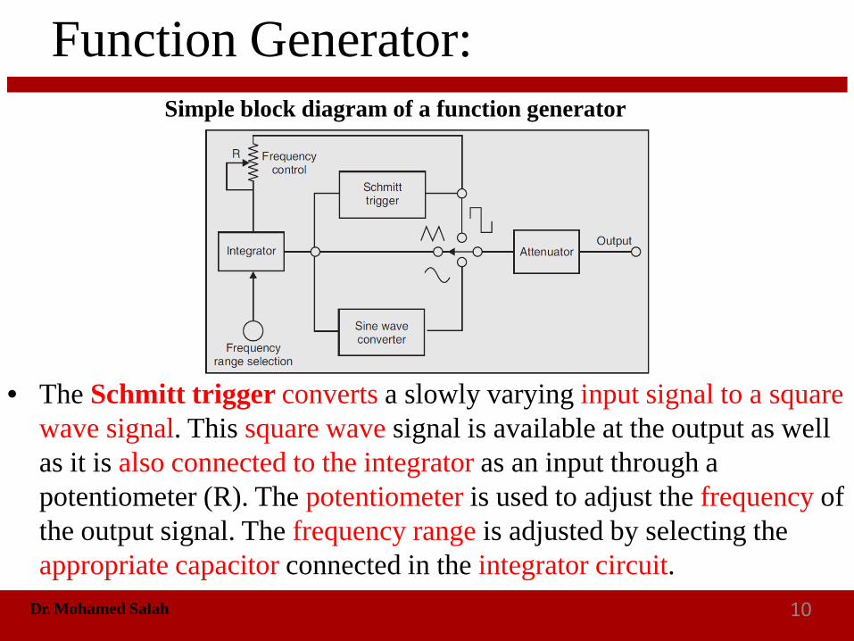
• The major parts of a function generator are Schmitt trigger, integrator, sine-wave converter and an attenuator.
Simple block diagram of a function generator
Function Generator:
Dr. Mohamed Salah 10
• The Schmitt trigger converts a slowly varying input signal to a square wave signal. This square wave signal is available at the output as well as it is also connected to the integrator as an input through a potentiometer (R). The potentiometer is used to adjust the frequency of the output signal. The frequency range is adjusted by selecting the appropriate capacitor connected in the integrator circuit.
Simple block diagram of a function generator

Function Generator:
Dr. Mohamed Salah 11
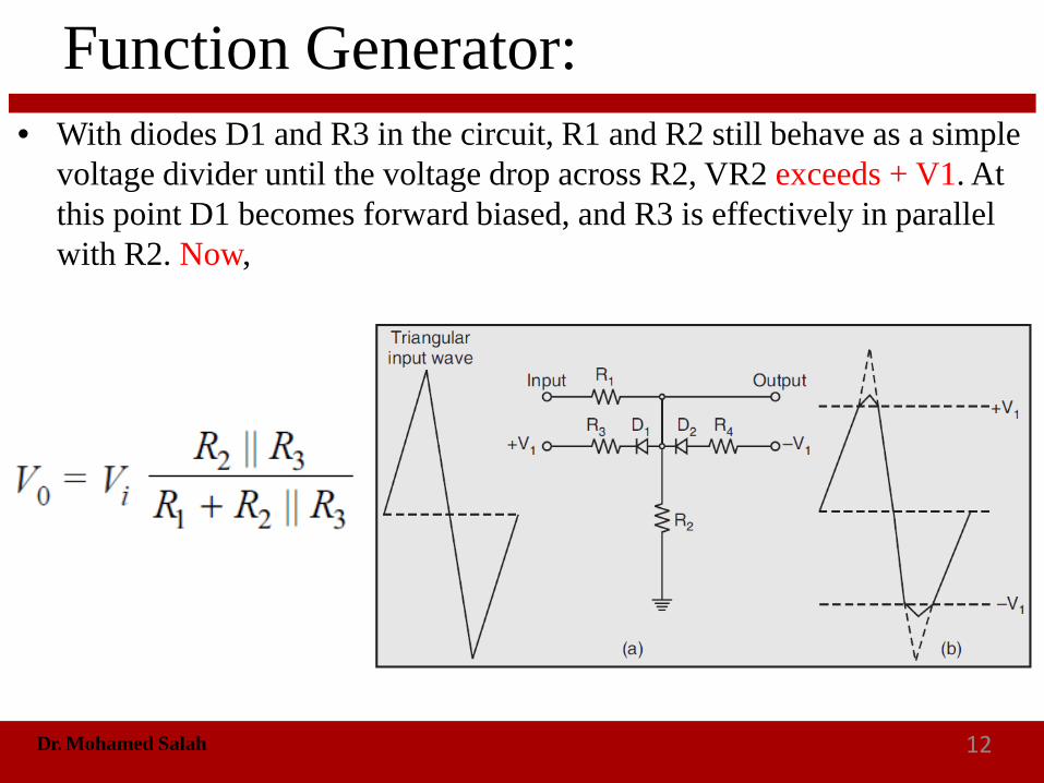
• The sine-wave converter is a six-level (or more) diode-resistor loading circuit. Consider a simple diode-resistor circuit shown in figure is used to convert a triangular wave into a sine wave.
• Note that if diodes D1 and D2 and resistors R3 and R4 were not present in the figure shown, R1 and R2 would simply behave as a voltage divider. In this case, the output from the circuit would be an attenuated version of the triangular wave:
Function Generator:
Dr. Mohamed Salah 12
• With diodes D1 and R3 in the circuit, R1 and R2 still behave as a simple voltage divider until the voltage drop across R2, VR2 exceeds + V1. At this point D1 becomes forward biased, and R3 is effectively in parallel with R2. Now,

Function Generator:
Dr. Mohamed Salah 13
• Output voltage levels above + V1 are attenuated to a greater extent than levels below + V1. Consequently, the output voltage rises less steeply than without D1 and R3 in the circuit (refer to Fig. (b)). When the output falls below + V1, the diode D1 is reverse biased. As a result of this, R3 is no longer in parallel with R2, and the attenuation is once again. Similarly, during the negative half cycle of the input, the output voltage,

Function Generator:
Dr. Mohamed Salah 14
• When V0 goes below – V1. Then D2 becomes forward biased, putting R4 in parallel with R2 and making,
• With R3 = R4, the negative half-cycle of the output is similar in shape to the positive half cycle.
Function Generator:
Dr. Mohamed Salah 15
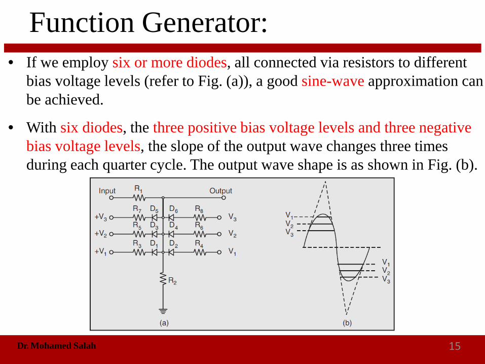
• If we employ six or more diodes, all connected via resistors to different bias voltage levels (refer to Fig. (a)), a good sine-wave approximation can be achieved.
• With six diodes, the three positive bias voltage levels and three negative bias voltage levels, the slope of the output wave changes three times during each quarter cycle. The output wave shape is as shown in Fig. (b).

Function Generator:
Dr. Mohamed Salah 16
Applications:
Product design.
Training.
Manufacturing production test.
Field repair.
Bench calibration and repair.
Laboratory, research, and education.
Testing amplifiers, filter and digital circuits.
Function Generator:
Dr. Mohamed Salah 17
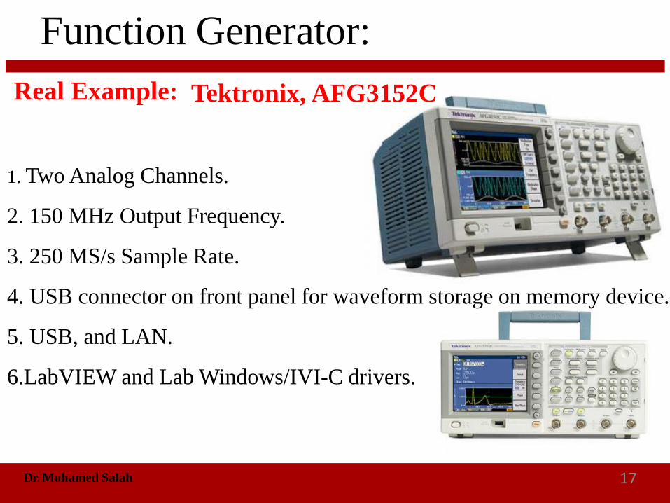
Real Example:
1. Two Analog Channels.
2. 150 MHz Output Frequency.
3. 250 MS/s Sample Rate.
4. USB connector on front panel for waveform storage on memory device.
5. USB, and LAN.
6.LabVIEW and Lab Windows/IVI-C drivers.
Tektronix, AFG3152C

Dr. Mohamed Salah 18
Mini-project
Smart Energy MeterObjective: Design and implementation of energy meter to
compute some loads energy consumption.
Oral Discussion: November 25th 2019
Hardware discussion : December 16th 2019

Dr. Mohamed Salah 19
Mini-project
Smart Energy MeterOral Discussion: November 25th 2019
Report: 4 to 6 pages includes,• Title, objectives, schematic diagrams.
• Hardware components.
• Software and programs as well as the data sheets as appendices.
• Prototype setup, calibration, and device test plan.

Theoretical Part:
Dr. Mohamed Salah 20
Scale-of-2000 Counter Report:
Quiz: December 2nd 2019
Digital circuit Simulation: December 9th 2019